US9813982B2 - Combining power from electrically isolated power paths for powering remote units in a distributed antenna system(s) (DASs) - Google Patents
Combining power from electrically isolated power paths for powering remote units in a distributed antenna system(s) (DASs) Download PDFInfo
- Publication number
- US9813982B2 US9813982B2 US15/585,688 US201715585688A US9813982B2 US 9813982 B2 US9813982 B2 US 9813982B2 US 201715585688 A US201715585688 A US 201715585688A US 9813982 B2 US9813982 B2 US 9813982B2
- Authority
- US
- United States
- Prior art keywords
- power
- remote unit
- input
- electrically isolated
- ports
- Prior art date
- Legal status (The legal status is an assumption and is not a legal conclusion. Google has not performed a legal analysis and makes no representation as to the accuracy of the status listed.)
- Active
Links
Images


Classifications
-
- H—ELECTRICITY
- H04—ELECTRIC COMMUNICATION TECHNIQUE
- H04W—WIRELESS COMMUNICATION NETWORKS
- H04W52/00—Power management, e.g. TPC [Transmission Power Control], power saving or power classes
-
- G—PHYSICS
- G05—CONTROLLING; REGULATING
- G05F—SYSTEMS FOR REGULATING ELECTRIC OR MAGNETIC VARIABLES
- G05F3/00—Non-retroactive systems for regulating electric variables by using an uncontrolled element, or an uncontrolled combination of elements, such element or such combination having self-regulating properties
- G05F3/02—Regulating voltage or current
- G05F3/08—Regulating voltage or current wherein the variable is dc
-
- H—ELECTRICITY
- H02—GENERATION; CONVERSION OR DISTRIBUTION OF ELECTRIC POWER
- H02J—CIRCUIT ARRANGEMENTS OR SYSTEMS FOR SUPPLYING OR DISTRIBUTING ELECTRIC POWER; SYSTEMS FOR STORING ELECTRIC ENERGY
- H02J4/00—Circuit arrangements for mains or distribution networks not specified as ac or dc
-
- H—ELECTRICITY
- H04—ELECTRIC COMMUNICATION TECHNIQUE
- H04L—TRANSMISSION OF DIGITAL INFORMATION, e.g. TELEGRAPHIC COMMUNICATION
- H04L12/00—Data switching networks
- H04L12/02—Details
- H04L12/10—Current supply arrangements
-
- H—ELECTRICITY
- H04—ELECTRIC COMMUNICATION TECHNIQUE
- H04W—WIRELESS COMMUNICATION NETWORKS
- H04W72/00—Local resource management
- H04W72/04—Wireless resource allocation
- H04W72/044—Wireless resource allocation based on the type of the allocated resource
-
- H—ELECTRICITY
- H04—ELECTRIC COMMUNICATION TECHNIQUE
- H04W—WIRELESS COMMUNICATION NETWORKS
- H04W88/00—Devices specially adapted for wireless communication networks, e.g. terminals, base stations or access point devices
- H04W88/08—Access point devices
- H04W88/085—Access point devices with remote components
-
- H—ELECTRICITY
- H04—ELECTRIC COMMUNICATION TECHNIQUE
- H04L—TRANSMISSION OF DIGITAL INFORMATION, e.g. TELEGRAPHIC COMMUNICATION
- H04L12/00—Data switching networks
- H04L12/28—Data switching networks characterised by path configuration, e.g. LAN [Local Area Networks] or WAN [Wide Area Networks]
- H04L12/40—Bus networks
- H04L12/40006—Architecture of a communication node
- H04L12/40045—Details regarding the feeding of energy to the node from the bus
Definitions
- the technology of the present disclosure relates generally to combining power from electrically isolated power paths for powering remote units in distributed antenna systems (DASs).
- DASs distributed antenna systems
- Wireless communication is rapidly growing, with ever-increasing demands for high-speed mobile data communication.
- local area wireless services e.g., so-called “wireless fidelity” or “WiFi” systems
- WiFi wireless fidelity
- wide area wireless services are being deployed in many different types of areas (e.g., coffee shops, airports, libraries, etc.).
- Distributed communications or antenna systems communicate with wireless devices called “clients,” “client devices,” or “wireless client devices,” which must reside within the wireless range or “cell coverage area” in order to communicate with an access point device.
- Distributed antenna systems are particularly useful to be deployed inside buildings or other indoor environments where client devices may not otherwise be able to effectively receive radio-frequency (RF) signals from a source, such as a base station for example.
- RF radio-frequency
- Example applications where distributed antenna systems can be used to provide or enhance coverage for wireless services include public safety, cellular telephony, wireless local access networks (LANs), location tracking, and medical telemetry inside buildings and over campuses.
- Antenna coverage areas can be formed by remotely distributed antenna units, also referred to as remote units (RUs).
- the remote units each contain or are configured to couple to one or more antennas configured to support the desired frequency(ies) or polarization to provide the antenna coverage areas.
- Antenna coverage areas can have a radius in the range from a few meters up to twenty meters as an example. Combining a number of remote units creates an array of antenna coverage areas. Because the antenna coverage areas each cover small areas, there typically may be only a few users (clients) per antenna coverage area. This arrangement generates a uniform high quality signal enabling high throughput supporting the required capacity for the wireless system users.
- FIG. 1 illustrates distribution of communications services to coverage areas 100 ( 1 )- 100 (N) of a DAS 102 , wherein ‘N’ is the number of coverage areas.
- These communications services can include cellular services, wireless services such as RFID tracking, Wireless Fidelity (WiFi), local area network (LAN), WLAN, and combinations thereof, as examples.
- the coverage areas 100 ( 1 )- 100 (N) may be remotely located.
- the remote coverage areas 100 ( 1 )- 100 (N) are created by and centered on remote units 104 ( 1 )- 104 (N) connected to a central unit 106 (e.g., a head-end controller or head-end unit).
- the central unit 106 may be communicatively coupled to a base station 108 .
- the central unit 106 receives downlink communications signals 110 D in multiple frequency bands for different communications services from the base station 108 to be distributed to the remote units 104 ( 1 )- 104 (N).
- the remote units 104 ( 1 )- 104 (N) are configured to receive downlink communications signals 110 D from the central unit 106 over a communications medium 112 to be distributed as downlink communications signals 110 D to the respective coverage areas 100 ( 1 )- 100 (N) of the remote units 104 ( 1 )- 104 (N).
- Each remote unit 104 ( 1 )- 104 (N) may include an RF transmitter/receiver (not shown) and a respective antenna 114 ( 1 )- 114 (N) operably connected to the RF transmitter/receiver to wirelessly distribute the communications services to client devices 116 within their respective coverage areas 100 ( 1 )- 100 (N).
- the remote units 104 ( 1 )- 104 (N) are also configured to receive uplink communications signals 110 U in multiple frequency bands over antennas 114 ( 1 )- 114 (N) from the client devices 116 in their respective coverage areas 100 ( 1 )- 100 (N) to be distributed over the communications medium 112 to the central unit 106 .
- Power is provided from one or more power sources to the remote units 104 ( 1 )- 104 (N) in the DAS 102 to provide power for the power-consuming components in the remote units 104 ( 1 )- 104 (N).
- the remote units 104 ( 1 )- 104 (N) may receive power P over long wire electrical conductor pairs 118 (“wire pair 118 ”) provided in the communications medium 112 from one or more power sources 120 (“power source 120 ”).
- the power source 130 may be remote to the remote units 104 ( 1 )- 104 (N) and provided at the central unit 106 or other location in the DAS 102 .
- the power source 120 may be either an alternative current (AC) or direct current (DC) power supply.
- Each wire pair 118 may carry a limited amount of current or voltage, which may be dictated by safety regulations or by physical properties of the wire pairs 118 , such as their diameter and length. However, in some cases, one or more of the remote units 104 ( 1 )- 104 (N) may require more power than can be carried by a single wire pair 118 .
- NEC National Electrical Code
- Class 2 directives may limit the power that can be provided by a single power supply to 100 VA (Volt-Ampere).
- One solution to deliver more power to the remote units 104 ( 1 )- 104 (N) is to connect multiple wire pairs 118 from multiple power output ports 122 ( 1 )- 122 (X) to each remote unit 104 ( 1 )- 104 (N).
- each wire pair 118 provides power up to its limited power level.
- the power provided by all wire pairs 118 can be combined in parallel to provide a greater combined power to a remote unit 104 ( 1 )- 104 (N).
- the voltages at the end of each wire pair 118 may be different due to different voltage drop on the wires, differences in the adjustment of the power supply 120 , and/or differences in components' tolerances in the power output ports 122 ( 1 )- 122 (X) of the power supply 120 .
- each wire pair 118 will cause the power supply 120 to distribute different current and thus different power P on power output ports 122 ( 1 )- 122 (X) to a remote unit 104 ( 1 )- 104 (N). In such case, some power output ports 122 ( 1 )- 122 (X) will deliver lower power while the other power output ports 122 ( 1 )- 122 (X) will deliver higher power. If power P pulled by the power supply 120 reaches the limit allowed by safety regulations or capabilities for a given power output port(s) 122 ( 1 )- 122 (X), the power supply 120 may shut down thereby interrupting power P to the remote units 104 ( 1 )- 104 (N).
- Embodiments disclosed herein include combining of power from electrically isolated power paths for powering remote units in distributed antenna systems (DASs).
- DASs distributed antenna systems
- one or more remote units in a DAS include multiple input power ports for receiving power from multiple power paths.
- Each power path is capable of distributing a given maximum power based on its respective power supply and the power handling capability of the respective power path.
- the received power from each input power port in a remote unit is combined to provide a combined output power for powering the remote unit.
- the remote unit can be powered by the combined output power if the remote unit requires more power for operation than can be supplied over a single power path.
- the input power ports in the remote unit are electrically isolated from each other. Further, in some embodiments, to provide for the received power on the multiple power inputs ports to be proportionally provided in the combined power according to the maximum power supplying capabilities of the respective power supplies, a controller is provided. The controller is configured to selectively control the amount of power provided from each power input port to the combined output power, based on the determined available power on each multiple input power port.
- the remote unit can tolerate inaccuracies in the output power from the power supplies.
- the type and length of wires used in the power paths for delivering power to the power input ports of a remote unit can cause the remote unit to draw power beyond the limits or regulations of a given power supply.
- This can simplify installation procedures for power supplies and remote units in a DAS, because in-field calibrations of power supplies by technicians based on variations in power supplies and power paths may be avoided.
- the remote unit can work with multiple types of power supplies, which can have different power delivery capabilities or regulations.
- the remote unit comprises a plurality of internal power paths each configured to carry power to a combined power node coupled to at least one remote unit load to provide a combined output power to the at least one remote unit load.
- the remote unit also comprises a plurality of input power ports provided in a respective internal power path among the plurality of internal power paths, each input power port among the plurality of input power ports configured to receive input power from a respective external power path in a DAS.
- the remote unit also comprises a plurality of isolation circuits provided in a respective internal power path among the plurality of internal power paths.
- Each isolation circuit among the plurality of isolation circuits is configured to receive the input power from the respective input power port and provide an electrically isolated output power based on the received input power at the combined power node to provide the combined output power.
- the remote unit also comprises a plurality of control circuits provided between the combined power node and the plurality of isolation circuits in a respective internal power path among the plurality of internal power paths to control the electrically isolated output power provided to the combined power node.
- the remote unit also comprises a controller configured to selectively control the plurality of control circuits to control the electrically isolated output power delivered from each isolation circuit in the respective internal power path to the combined power node into the combined output power.
- Another embodiment of the disclosure relates to a method of combining power received from multiple input ports in a remote unit for a DAS.
- the method comprises receiving input power from a plurality of external power paths in a DAS into a plurality of input power ports each provided in a respective internal power path among a plurality of internal power paths.
- the method also comprises providing a plurality of electrically isolated output powers based on the received input power from a respective input power port among the plurality of input power ports.
- the method also comprises selectively controlling an amount of electrically isolated output power delivered in each respective internal power path, to a combined power node into a combined output power to be provided to at least one remote unit load.
- the DAS comprises a central unit.
- the central unit is configured to distribute at least one downlink communications signal over at least one communications medium to at least one remote unit among a plurality of remote units.
- the central unit is also configured to receive at least one uplink communications signal over the at least one communications medium from at least one remote unit among the plurality of remote units.
- Each of the plurality of remote units is configured to receive the at least one downlink communications signal over the at least one communications medium from the central unit and distribute the received at least one downlink communications signal from the central unit to at least one client device.
- Each of the plurality of remote units is also configured to receive the at least one uplink communications signal from the at least one client device and distribute the received at least one uplink communications signal over the at least one communications medium to the central unit.
- Each of the plurality of remote units further comprises a plurality of internal power paths each configured to carry power to a combined power node coupled to at least one remote unit load to provide a combined output power to the at least one remote unit load.
- Each of the plurality of remote units further comprises a plurality of input power ports provided in a respective internal power path among the plurality of internal power paths, each input power port among the plurality of input power ports configured to receive input power from a respective external power path in a DAS.
- Each of the plurality of remote units further comprises a plurality of isolation circuits provided in a respective internal power path among the plurality of internal power paths. Each isolation circuit among the plurality of isolation circuits is configured to receive the input power from a respective input power port and provide an electrically isolated output power based on the received input power at the combined power node to provide the combined output power.
- Each of the plurality of remote units further comprises a plurality of control circuits provided between the combined power node and the plurality of isolation circuits in a respective internal power path among the plurality of internal power paths.
- Each of the plurality of remote units further comprises a controller configured to selectively control an amount of electrically isolated output power delivered from the isolation circuit in the respective internal power path, to the combined power node into the combined output power.
- FIG. 1 is a schematic diagram of an exemplary distributed antenna system (DAS) capable of distributing radio frequency (RF) communications services to client devices;
- DAS distributed antenna system
- RF radio frequency
- FIG. 2 is a schematic diagram of an exemplary remote unit that can be provided in a DAS, wherein the remote unit is configured to combine received power from electrically isolated power ports each receiving power from respective external power paths, for powering the remote unit;
- FIG. 3 is a flowchart illustrating an exemplary process of the remote unit in FIG. 2 receiving input power from a plurality of external power paths into a plurality of input power ports, and selectively controlling the contribution of power from each of the input power ports to a combined power node;
- FIG. 4 is a timing diagram illustrating exemplary duty cycles of control circuits in each output power path in the remote unit in FIG. 2 controlling the portion of time that power received from a respective input power port is provided to a combined output power;
- FIG. 5 is a schematic diagram illustrating more detail of an exemplary available power measurement circuit provided in the remote unit in FIG. 2 for measuring the available power from a power supply supplying power over an external power path to a respective input power port in the remote unit;
- FIG. 6A is a flowchart illustrating an exemplary process of measuring the available power from a respective power supply supplying power over a respective external power path to a respective input power port in the remote unit;
- FIG. 6B is a flowchart illustrating an exemplary monitoring process of the remote unit in FIG. 2 determining isolation circuit intolerances to perform a correction process to compensate the output power for any such intolerances;
- FIG. 7 is a schematic diagram of another exemplary remote unit that can be provided in a DAS, wherein the remote unit is configured to combine received power from electrically isolated power ports each receiving power from respective external power paths, to multiple output loads for powering the remote unit;
- FIG. 8 is a schematic diagram of an exemplary DAS employing one or more remote units configured to combine received power from electrically isolated power ports each receiving power from respective power paths, for powering the remote unit;
- FIG. 9 is a partially schematic cut-away diagram of an exemplary building infrastructure in which a DAS can be employed, wherein one or more of the remote units is configured to combine received power from electrically isolated power ports each receiving power from respective external power paths, for powering the remote unit; and
- FIG. 10 is a schematic diagram of a generalized representation of an exemplary controller that can be included in a remote unit for measuring the available power from a power supply supplying power over a respective external power path to a respective input power port in the remote unit and/or proportionally controlling the contribution of power from each of the input power ports to the combined output power based on the measured available power from the respective power supplies, wherein the exemplary computer system is adapted to execute instructions from an exemplary computer readable medium.
- Embodiments disclosed herein include combining of power from electrically isolated power paths for powering remote units in distributed antenna systems (DASs).
- DASs distributed antenna systems
- one or more remote units in a DAS include multiple input power ports for receiving power from multiple power paths.
- Each power path is capable of distributing a given maximum power based on its respective power supply and the power handling capability of the respective power path.
- the received power from each input power port in a remote unit is combined to provide a combined output power for powering the remote unit.
- the remote unit can be powered by the combined output power if the remote unit requires more power for operation than can be supplied over a single power path.
- the input power ports in the remote unit are electrically isolated from each other. Further, in some embodiments, to provide for the received power on the multiple power inputs ports to be proportionally provided in the combined output power according to the maximum power supplying capabilities of the respective power supplies, a controller is provided. The controller is configured to selectively control the amount of power provided from each power input port to the combined output power, based on the determined available power on each multiple input power port.
- the remote unit can tolerate inaccuracies in the output power from the power supplies.
- the type and length of wires used in the power paths for delivering power to the power input ports of a remote unit can cause the remote unit to draw power beyond the limits or regulations of a given power supply.
- This can simplify installation procedures for power supplies and remote units in a DAS, because in-field calibrations of power supplies by technicians based on variations in power supplies and power paths may be avoided.
- the remote unit can work with multiple types of power supplies, which can have different power delivery capabilities or regulations.
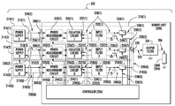
- FIG. 2 is a schematic diagram of an exemplary remote unit 200 that can be provided in a DAS.
- a plurality of the remote units 200 may be provided in a DAS.
- the remote unit 200 is configured to distribute communications services in a DAS 202 . These communications services are provided by power-consuming components represented by a remote unit load 204 (“load 204 ”) in FIG. 2 .
- load 204 can represent multiple different loads in the remote unit 200 .
- the remote unit 200 is configured to provide an output power 206 to the load 204 for operations.
- the remote unit 200 can be configured to receive input power in multiple input power ports over multiple respective power paths in the DAS 202 .
- the remote unit 200 in FIG. 2 contains multiple input power ports 208 ( 1 )- 208 (Q). ‘Q’ signifies that any number of input power ports 208 desired can be provided in the remote unit 200 .
- Each input power port 208 ( 1 )- 208 (Q) is configured to receive input power 210 ( 1 )- 210 (Q) from a respective power wire pair 212 ( 1 )- 212 (Q) from a respective external power path 214 ( 1 )- 214 (Q) in the DAS 202 .
- Multiple power supplies 216 ( 1 )- 216 (Q) are provided in the DAS 202 to supply the input power 210 ( 1 )- 210 (Q) over the respective power wire pairs 212 ( 1 )- 212 (Q) in the external power path 214 ( 1 )- 214 (Q) to the remote unit 200 .
- the power supplies 216 ( 1 )- 216 (Q) may be located at the remote unit 200 or remotely from the remote unit 200 .
- Each external power path 214 ( 1 )- 214 (Q) is capable of distributing a given maximum input power 210 ( 1 )- 210 (Q) based on the respective power supply 216 ( 1 )- 216 (Q) and the power handling capability of the respective power wire pair 212 ( 1 )- 212 (Q).
- the remote unit 200 is configured to receive the input power 210 ( 1 )- 210 (Q) from the multiple power supplies 216 ( 1 )- 216 (Q) in case the power needed to power the load 204 is greater than can be supplied by a single power supply 216 among the multiple power supplies 216 ( 1 )- 216 (Q). For example, there may be restrictions on the maximum power that can be supplied by a power supply over a power wire pair 212 to the remote unit 200 .
- the remote unit 200 includes a plurality of internal power paths 218 ( 1 )- 218 (Q) for routing the received input power 210 ( 1 )- 210 (Q) from the input power ports 208 ( 1 )- 208 (Q) to the load 204 .
- Each of the internal power paths 218 ( 1 )- 218 (Q) are coupled to a combined power node 220 to provide a combined output power 222 for powering the load 204 .
- an output filter 224 is provided to filter the combined output power 222 into the output power 206 provided to the load 204 .
- the input power ports 208 ( 1 )- 208 (Q) in the remote unit 200 are electrically isolated from each other.
- a plurality of isolation circuits 226 ( 1 )- 226 (Q) are provided in respective internal power paths 218 ( 1 )- 218 (Q).
- the isolation circuits 226 ( 1 )- 226 (Q) may be direct current (DC) to DC (DC-DC) converters if the input power 210 ( 1 )- 210 (Q) is DC input power to provide the output power 206 as electrically isolated DC output power.
- isolation circuits 226 ( 1 )- 226 (Q) may be alternating current (AC) to DC (AC-DC) converters if the input power 210 ( 1 )- 210 (Q) is AC input power to provide the output power 206 as electrically isolated DC output power.
- Each isolation circuit 226 ( 1 )- 226 (Q) is configured to receive the respective input power 210 ( 1 )- 210 (Q) from the respective input power port 208 ( 1 )- 208 (Q). Each isolation circuit 226 ( 1 )- 226 (Q) is further configured to provide a respective electrically isolated output power 228 ( 1 )- 228 (Q) to the combined power node 220 . The electrically isolated output powers 228 ( 1 )- 228 (Q) received at the combined power node 220 are combined together to form the combined output power 222 .
- the isolation circuits 226 ( 1 )- 226 (Q) are capable of providing stable electrically isolated output powers 228 ( 1 )- 228 (Q) to provide a stable combined output power 222 . Also, by providing the isolation circuits 226 ( 1 )- 226 (Q) in the respective internal power paths 218 ( 1 )- 218 (Q), the input power 210 ( 1 )- 210 (Q) being higher from one or more power supplies 216 ( 1 )- 216 (Q) than other power supplies 216 ( 1 )- 216 (Q) on the return paths 230 ( 1 )- 230 (Q) of the respective power wire pairs 212 ( 1 )- 212 (Q) does not cause a greater amount of power to be pulled beyond the power supply capability limits of a respective power supply 216 ( 1 )- 216 (Q).
- Optional input filters 232 ( 1 )- 232 (Q) can be provided in respective internal power paths 218 ( 1 )- 218 (Q) to filter the electrically isolated output powers 228 ( 1 )- 228 (Q) before being provided to the combined power node 220 .
- the load 204 may not require the maximum amount of power that can be provided in the output power 206 from the contribution of the electrically isolated output powers 228 ( 1 )- 228 (Q) from the isolation circuits 226 ( 1 )- 226 (Q) to the combined power node 220 .
- a plurality of control circuits 234 ( 1 )- 234 (Q) can be provided in each internal power path 218 ( 1 )- 218 (Q), respectively.
- the control circuits 234 ( 1 )- 234 (Q) may be switching circuits in the form of switches.
- controller 236 is provided in the remote unit 200 that is configured to control operation of the control circuits 234 ( 1 )- 234 (Q) to control the amount of the electrically isolated output power 228 ( 1 )- 228 (Q) to be delivered and combined at the combined power node 220 in the combined output power 222 .
- the controller 236 may be a microcontroller, microprocessor, logic circuit, or other control circuit.
- the controller 236 can selectively control the control circuits 234 ( 1 )- 234 (Q) to couple the electrically isolated output power 228 ( 1 )- 228 (Q) to the combined power node 220 or decouple the electrically isolated output power 228 ( 1 )- 228 (Q) from the combined power node 220 .
- the controller 236 is configured to provide a control signal 238 ( 1 )- 238 (Q) to each of the respective control circuits 234 ( 1 )- 234 (Q) to control the control circuits 234 ( 1 )- 234 (Q).
- the controller 236 can selectively control the control circuits 234 ( 1 )- 234 (Q) to provide different levels of combined output power 222 to the load 204 depending on the power needed by the load 204 for operation.
- the remote unit 200 may also be designed to only need to power certain portions of the load 204 based on operation of the remote unit 200 .
- Capacitor circuits 240 ( 1 )- 240 (Q) may be provided in each of the respective internal power paths 218 ( 1 )- 218 (Q) between the isolation circuits 226 ( 1 )- 226 (Q) and the control circuits 234 ( 1 )- 234 (Q) to store energy from the electrically isolated output power 228 ( 1 )- 228 (Q) to smooth out or average any power bursts of the electrically isolated output power 228 ( 1 )- 228 (Q).
- the capacitor circuits 240 ( 1 )- 240 (Q) may each be comprised of a single capacitor or network of capacitors.
- the isolation circuits 226 ( 1 )- 226 (Q) may have an adjustable output power input 237 ( 1 )- 237 (Q), in the form of a current limiter input or adjustable output voltage that can be set by the controller 236 according to adjustment signals 239 ( 1 )- 239 (Q).
- the adjustment signals 239 ( 1 )- 239 (Q) may be either analog or digital signals depending on the type of isolation circuits 226 ( 1 )- 226 (Q) employed. Using these current limiters or output voltage adjustment mechanisms, it is possible to limit the electrically isolated output power 228 ( 1 )- 228 (Q) delivered through each internal power path 218 ( 1 )- 218 (Q) to the maximum allowed combined output power 222 .
- the current of the electrically isolated output power 228 ( 1 )- 228 (Q) of a specific isolation circuit 226 will increase or decrease depending on the voltage difference between the electrically isolated output power 228 ( 1 )- 228 (Q) of the specific isolation circuit 226 and the combined power node 220 , divided by the resistance of the electrical path between these nodes.
- the series resistance includes both the respective input filter 232 and the control circuit 234 resistance.
- an additional series resistor may be added to the output of the isolation circuits 226 ( 1 )- 226 (Q), to enable fine tuning of the output current or voltage of the electrically isolated output power 228 ( 1 )- 228 (Q).
- FIG. 3 is a flowchart illustrating an exemplary process 300 of the remote unit 200 in FIG. 2 receiving the input power 210 ( 1 )- 210 (Q) from input power ports 208 ( 1 )- 208 (Q) and selectively controlling the control circuits 234 ( 1 )- 234 (Q) to control contribution of each electrically isolated output power 228 ( 1 )- 228 (Q) to the combined output power 222 at the combined power node 220 .
- remote unit 200 receives the input power 210 ( 1 )- 210 (Q) from the external power paths 214 ( 1 )- 214 (Q) in the DAS 202 into the input power ports 208 ( 1 )- 208 (Q) each provided in a respective internal power path 218 among a plurality of internal power paths 218 ( 1 )- 218 (Q) (block 302 ).
- the isolation circuits 226 ( 1 )- 226 (Q) provide the electrically isolated output powers 228 ( 1 )- 228 (Q) based on the received input power 210 ( 1 )- 210 (Q) from a respective input power port 208 among the plurality of input power ports 208 ( 1 )- 208 (Q) (block 304 ).
- the controller 236 selectively controls an amount of the electrically isolated output power 228 ( 1 )- 228 (Q) delivered in each respective internal power path 218 ( 1 )- 218 (Q), to the combined power node 220 into the combined output power 222 to be provided to the load 204 (block 306 ).
- electrically isolated output power 228 ( 1 )- 228 (Q) By proportionally combining electrically isolated output power 228 ( 1 )- 228 (Q) based on the power supplying capability of the respective power supplies 216 ( 1 )- 216 (Q), the remote unit 200 can tolerate inaccuracies in the output power from the power supplies 216 ( 1 )- 216 (Q).
- the maximum power available to be provided to the load 204 is 240 W (i.e., 70 W+80 W+90 W).
- the combined output power 222 can be provided as a proportion of electrically isolated output power 228 ( 1 )- 228 ( 3 ) in accordance with the relative maximum power supplying capabilities of the three (3) power supplies 216 ( 1 )- 216 ( 3 ).
- the control circuits 234 ( 1 )- 234 ( 3 ) could be controlled to be turned on and turned off by the controller 236 to pulse width modulate (PWM) the electrically isolated output power 228 ( 1 )- 228 ( 3 ) in proportion to the power supplying capabilities of the respective power supplies 216 ( 1 )- 216 ( 3 ).
- PWM pulse width modulate
- the three (3) electrically isolated output powers 228 ( 1 )- 228 ( 3 ) are pulse width modulated (PWM) by the controller 236 by controlling respective control circuits 234 ( 1 )- 234 ( 3 ).
- the combined output power 222 at the combined power node 220 of the first electrically isolated output power 228 ( 1 ) is PWM at 29.2% (i.e., 70 W/240 W). This is shown by time period t 1 to t 2 of period T in FIG. 4 .
- the second electrically isolated output power 228 ( 2 ) is PWM by the controller 236 at 33.3% (80 W/240 W). This is shown by time period t 2 to t 3 in period T in FIG. 4 .
- the third electrically isolated output power 228 ( 3 ) is PWM by the controller 236 at 37.5% (90 W/240 W) of time period T. This is shown by time period t 3 to t 4 in period T in FIG. 4 .
- the remote unit 200 additionally includes optional power measurement circuits 242 ( 1 )- 242 (Q) provided in each internal power path 218 ( 1 )- 218 (Q) to measure the power supplying capability of the power supplies 216 ( 1 )- 216 (Q) supplying power to the input power ports 208 ( 1 )- 208 (Q).
- the relative power supplying capabilities of the power supplies 216 ( 1 )- 216 (Q) can be determined by the controller 236 , to be able to proportionally control providing the electrically isolated output power 228 ( 1 )- 228 (Q) to the combined power node 220 .
- the power measurement circuits 242 ( 1 )- 242 (Q) are provided between respective input power ports 208 ( 1 )- 208 (Q) and the isolation circuits 226 ( 1 )- 226 (Q) in the remote unit 200 .
- the power measurement circuits 242 ( 1 )- 242 (Q) are configured to measure the available power provided to the input power ports 208 ( 1 )- 208 (Q) by the respective power supplies 216 ( 1 )- 216 (Q).
- the power measurement circuits 242 ( 1 )- 242 (Q) are further configured to provide the measured available power from the input power ports 208 ( 1 )- 208 (Q) to the controller 236 .
- the controller 236 is configured to instruct the power measurement circuits 242 ( 1 )- 242 (Q) through control signals 244 ( 1 )- 244 (Q) to measure the available power that can be provided by the power supplies 216 ( 1 )- 216 (Q) to the respective input power ports 208 ( 1 )- 208 (Q).
- the power measurement circuits 242 ( 1 )- 242 (Q) may be configured to measure the maximum available power that can be provided by the power supplies 216 ( 1 )- 216 (Q) to the respective input power ports 208 ( 1 )- 208 (Q).
- the controller 236 can use the determined available power that can be provided by the power supplies 216 ( 1 )- 216 (Q) to selectively control the control circuits 234 ( 1 )- 234 (Q) to deliver the electrically isolated output power 228 ( 1 )- 228 (Q) to the combined power node 220 based on the available power that can be supplied by the respective power supplies 216 ( 1 )- 216 (Q).
- the controller 236 may be configured to selectively control the control circuits 234 ( 1 )- 234 (Q) to proportionally deliver the electrically isolated output power 228 ( 1 )- 228 (Q) to the combined power node 220 based on the proportions of available power that can be supplied by the respective power supplies 216 ( 1 )- 216 (Q).
- FIG. 5 illustrates more exemplary detail of an exemplary power measurement circuit 242 provided in the remote unit 200 in FIG. 2 .
- Only one power measurement circuit 242 is shown for one internal power path 218 in the remote unit 200 in FIG. 5 receiving the input power 210 from a corresponding power supply 216 for simplicity in illustration purposes only.
- a plurality of power measurement circuits 242 ( 1 )- 242 (Q) can be provided corresponding to each internal power path 218 ( 1 )- 218 (Q), as illustrated in FIG. 2 .
- the power measurement circuit 242 is configured to measure the available power from a power supply 216 supplying the input power 210 over the external power path 214 to a respective input power port 208 .
- power measurement circuit 242 is configured to measure the maximum available power from a power supply 216 supplying the input power 210 over the external power path 214 to a respective input power port 208 .
- the power supply 216 is electrically connected through power wire pair 212 to the remote unit 200 to provide the input power 210 to the input power port 208 .
- the power wire pair 212 has a resistance represented by resistor (R) 500 .
- R resistor
- the input current I IN of the input power 210 is measured by a current measurement circuit 502 in the power measurement circuit 242 of the remote unit 200 .
- the input voltage V IN of the input power 210 is measured by a voltage measurement circuit 504 in the power measurement circuit 242 .
- the controller 236 can be configured to manage the measurement of the input current I IN and the input voltage V IN in the following exemplary available power measurement process 600 in FIG. 6A discussed below.
- the available power measurement process 600 begins with the controller 236 causing a switch circuit 506 in the respective internal power path 218 to temporarily disconnect the power measurement circuit 242 from any load, including a respective isolation circuit 226 and load 204 (see FIG. 2 ) (block 602 ).
- the controller 236 causes the switch circuit 506 to open by providing a switch control signal 508 on a switch control line 510 instructing the switch circuit 506 to open.
- the controller 236 causes a first load switch 512 coupled to a first load (LOAD A) 514 to close to couple the first load 514 to the power supply 216 (block 604 ).
- LOAD A first load
- the controller 236 causes the first load switch 512 to close by providing a switch control signal 516 on a switch control line 518 instructing the first load switch 512 to close.
- the controller 236 instructs the current measurement circuit 502 to measure the input power 210 on the input power port 208 with the first load 514 coupled to the power supply 216 by the first load switch 512 being closed (block 606 ).
- the controller 236 provides a current measurement signal 520 on a current measurement line 522 to cause the current measurement circuit 502 to measure the input current I IN while the first load 514 is coupled to the power supply 216 .
- the controller 236 also provides a voltage measurement signal 524 on a voltage measurement line 526 to cause the voltage measurement circuit 504 to measure the input voltage V IN while the first load 514 is coupled to the power supply 216 .
- the controller 236 causes a switch control signal 516 on a switch control line 518 to instruct the first load switch 512 to open (block 608 ).
- the controller 236 causes a second load switch 528 coupled to a second load (LOAD B) 530 to close to couple the second load 530 to the power supply 216 (block 610 ).
- the controller 236 causes the second load switch 528 to close by providing a switch control signal 532 on a switch control line 534 instructing the second load switch 528 to close.
- the controller 236 instructs the current measurement circuit 502 to measure the input power 210 on the input power port 208 with the second load 530 coupled to the power supply 216 by the second load switch 528 being closed (block 612 ).
- the controller 236 provides the current measurement signal 520 on the current measurement line 522 to cause the current measurement circuit 502 to measure the input current I IN while the second load 530 is coupled to the power supply 216 .
- the controller 236 also provides the voltage measurement signal 524 on the voltage measurement line 526 to cause the voltage measurement circuit 504 to measure the input voltage V IN while the second load 530 is coupled to the power supply 216 .
- V PS I IN-LOAD A *R LINE +V IN-LOAD A , for first load 514 (LOAD A ) (1)
- V PS I IN-LOAD B *R LINE +V IN-LOAD B , for second load 530 (LOAD B ) (2)
- I IN[Max] P O[MAX] /V PS , (3)
- V IN [@PS-MAX] V PS ⁇ I IN [Max] *R LINE (4)
- P IN [MAX] I IN [@PS-MAX] *V IN [@PS-MAX]
- each control circuit 234 ( 1 )- 234 (Q) in the remote unit 200 in FIG. 2 is defined as the ratio between on time and the period time T (see FIG. 4 ).
- each control circuit 234 ( 1 )- 234 ( 3 ) will be:
- the targeted power consumption from each of the power wire pairs 212 ( 1 )- 212 (Q) is based on a pre-defined balancing policy (i.e. different power consumption is requested)
- solving the above two equations (1) and (2) to get both the output voltage V PS and R LINE values is performed.
- the calculated output voltage V PS will be used in conjunction with the measured input current I IN to calculate the power consumption from the power supplies 216 ( 1 )- 216 (Q).
- the controller 236 can adjust the power consumption from each of the power wire pairs 212 ( 1 )- 212 (Q) to reach the targeted power consumption for the power supplies 216 ( 1 )- 216 (Q).
- a given control circuit 234 in the remote unit 200 in FIG. 2 may be open at exactly the same time that the other control circuits 234 are closed. However, a short delay may be inserted between the on states of the control circuit 234 ( 1 )- 234 (Q) for avoiding a situation where two control circuits 234 are on at the same time.
- the capacitor circuits 240 ( 1 )- 240 (Q) in each internal power path 218 ( 1 )- 218 (Q) can be used for averaging the power bursts that are sourced by the load 204 from each internal power path 218 ( 1 )- 218 (Q). During the off period, the capacitor circuits 240 ( 1 )- 240 (Q) are charged with energy (through the isolation circuits 226 ( 1 )- 226 (Q) of each internal power path 218 ( 1 )- 218 (Q)).
- the capacitor circuits 240 ( 1 )- 240 (Q) provide energy to the load 204 in addition to the input power 210 ( 1 )- 210 (Q) provided to the input power ports 208 ( 1 )- 208 (Q). Then, when the consumed power by the remote unit 200 is lower the maximum available power P T [Max] , the input power 210 ( 1 )- 210 (Q) consumed from each input power port 208 ( 1 )- 208 (Q) will be proportionally lower than the maximum power that is allowed to be consumed through the internal power paths 218 ( 1 )- 218 (Q).
- period time T can be determined according to the following considerations.
- capacitor circuits 240 ( 1 )- 240 (Q) supplement the energy when the respective control circuit 234 ( 1 )- 234 (Q) is on (i.e., connected to the load 204 ), for on time t ON , the voltage on the load 204 ( FIG. 2 ) drops gradually.
- a voltage drop of ⁇ V is allowed during on time t ON
- a current of I C is consumed by the capacitor circuits 240 ( 1 )- 240 (Q) during discharge.
- C is the capacitance of a respective capacitor circuit 240 ( 1 )- 240 (Q).
- the voltage of electrically isolated output power 228 ( 1 )- 228 (Q) as well as the resistance of the components on the output side of the respective internal power path 218 ( 1 )- 218 (Q) of the isolation circuits 226 ( 1 )- 226 (Q) may suffer from tolerance/variation due to limited component accuracy.
- a monitoring process 620 in FIG. 6B may be employed to determine the duty cycle (DC) of the control circuit 234 ( 1 )- 234 (Q) to compensate for the inefficiencies in the isolation circuits 226 ( 1 )- 226 (Q).
- the controller 236 uses the first load switch 512 to connect a minimum load, such as the first load 514 , to a respective internal power path 218 ( 1 )- 218 (Q) and sets a default or uniform duty cycle of all control circuits 234 ( 1 )- 234 (Q) (block 622 ).
- the controller 236 then performs the available power supplying capability of the power supplies 216 ( 1 )- 216 (Q) according to the example above, and reduces the results to fit the available power to the efficiency of the isolation circuits 226 ( 1 )- 226 (Q) (block 624 ).
- controller 236 executes an initial determination of the duty cycle of each control circuit 234 ( 1 )- 234 (Q) as previously discussed (block 626 ).
- controller 236 then instructs the power measurement circuits 242 ( 1 )- 242 (Q) to perform current and voltage measurements in each internal power path 218 ( 1 )- 218 (Q), as previously discussed (block 628 ).
- the controller 236 determines if the fit to power measurement calculations meet expectations for the isolation circuits 226 ( 1 )- 226 (Q) (block 630 ). If not, the controller 236 may optionally correct the duty cycle of the control circuits 234 ( 1 )- 234 (Q) to compensate for the isolation circuits 226 ( 1 )- 226 (Q) voltage mismatches on the electrically isolated output powers 228 ( 1 )- 228 (Q) due to the actual circuitry intolerances (block 632 ).
- controller 236 determines that the fit to power measurement calculations meet expectations for the isolation circuits 226 ( 1 )- 226 (Q)
- the controller 236 controls the first and second load switches 512 , 528 to connect the first and second loads 514 , 530 (or other loads) to the respective internal power paths 218 ( 1 )- 218 (Q), as previously discussed (block 634 ).
- the controller 236 determines if the fit to power measurement calculations were to expectations for the isolation circuits 226 ( 1 )- 226 (Q) with the first and second loads 514 , 530 connected (block 636 ).
- the controller 236 again optionally corrects the duty cycle of the control circuits 234 ( 1 )- 234 (Q) to compensate for the isolation circuits 226 ( 1 )- 226 (Q) voltage mismatches on the electrically isolated output powers 228 ( 1 )- 228 (Q) due to the actual circuitry intolerances (block 638 ). If controller 236 determines that the fit to power measurement calculations meet expectations for the isolation circuits 226 ( 1 )- 226 (Q), the controller 236 waits a period of time (Tx) to repeat the monitoring process by retuning to block 708 (block 640 ).
- Tx period of time
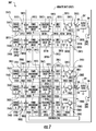
- FIG. 7 is a schematic diagram of another exemplary remote unit 200 ′ that can be provided in the DAS 202 ′, wherein the remote unit 200 ′ is configured to combine received power from electrically isolated power ports each receiving power from respective external power paths, to multiple output loads for powering the remote unit 200 ′.
- the remote unit 200 ′ is similar to the remote unit 200 in FIG.
- the load 204 is included to receive an output power 206 based on received power from the power supplies 216 ( 1 )- 216 (Q) over internal power paths 218 ( 1 )- 218 (Q) that coupled to the combined power node 220 to provide a combined output power 222 for powering the load 204 .
- common elements between the remote unit 200 in FIG. 2 and the remote unit 200 ′ in FIG. 7 are shown with common element numbers in FIGS. 2 and 7 , and thus are not necessary to re-describe.
- the remote unit 200 ′ also includes additional input power ports 208 ′( 1 )- 208 ′(R) configured to receive power from power supplies 214 ′( 1 )- 214 ′(R) to be electrically isolated and combined for providing power to an additional load 204 ′.
- the remote unit 200 ′ in FIG. 7 contains multiple second input power ports 208 ′( 1 )- 208 ′(R). ‘R’ signifies that any number of input power ports 208 ′ desired can be provided in the remote unit 200 ′.
- Each second input power port 208 ′( 1 )- 208 ′(R) is configured to receive second input power 210 ′( 1 )- 210 ′(R) from a respective second power wire pair 212 ′( 1 )- 212 ′(R) from a respective second external power path 214 ′( 1 )- 214 ′(R) in the DAS 202 ′.
- the multiple second power supplies 216 ′( 1 )- 216 ′(R) are provided in the DAS 202 ′ to supply the second input power 210 ′( 1 )- 210 ′(R) over the respective second power wire pairs 212 ′( 1 )- 212 ′(R) in the second external power path 214 ′( 1 )- 214 ′(R) to the remote unit 200 ′.
- the second power supplies 216 ′( 1 )- 216 ′(R) may be located at the remote unit 200 ′ or remotely from the remote unit 200 ′.
- Each second external power path 214 ′( 1 )- 214 ′(R) is capable of distributing a given second maximum input power 210 ′( 1 )- 210 ′(R) based on the respective second power supply 216 ′( 1 )- 216 ′(R) and the power handling capability of the respective second power wire pair 212 ′( 1 )- 212 ′(R).
- the remote unit 200 ′ is configured to receive the second input power 210 ′( 1 )- 210 ′(R) from the multiple second power supplies 216 ′( 1 )- 216 ′(R) in case the power needed to power the second, additional load 204 ′ is greater than can be supplied by a single second power supply 216 ′ among the multiple second power supplies 216 ′( 1 )- 216 ′(R). For example, there may be restrictions on the maximum power that can be supplied by a power supply over a second power wire pair 212 ′ to the remote unit 200 ′.
- the remote unit 200 ′ includes a plurality of second internal power paths 218 ′( 1 )- 218 ′(R) for routing the received second input power 210 ′( 1 )- 210 ′(R) from the second input power ports 208 ′( 1 )- 208 ′(R) to the second load 204 ′.
- Each of the second internal power paths 218 ′( 1 )- 218 ′(R) are coupled to a second combined power node 220 ′ to provide a second combined output power 222 ′ for powering the second load 204 ′.
- a second output filter 224 ′ is provided to filter the second combined output power 222 ′ into the second output power 206 ′ provided to the second load 204 ′.
- the second input power ports 208 ′( 1 )- 208 ′(R) in the remote unit 200 ′ are electrically isolated from each other.
- a plurality of second isolation circuits 226 ′( 1 )- 226 ′(R) are provided in respective internal power paths 218 ′( 1 )- 218 ′(R).
- the second isolation circuits 226 ′( 1 )- 226 ′(R) may be direct current (DC) to DC (DC-DC) converters if the second input power 210 ′( 1 )- 210 ′(R) is DC input power to provide the second output power 206 ′ as electrically isolated DC output power.
- second isolation circuits 226 ′( 1 )- 226 ′(R) may be alternating current (AC) to DC (AC-DC) converters if the second input power 210 ′( 1 )- 210 ′(R) is AC input power to provide the second output power 206 ′ as electrically isolated DC output power.
- Each second isolation circuit 226 ′( 1 )- 226 ′(R) is configured to receive the respective second input power 210 ′( 1 )- 210 ′(R) from the respective second input power port 208 ′( 1 )- 208 ′(R).
- Each second isolation circuit 226 ′( 1 )- 226 ′(R) is further configured to provide a respective second electrically isolated output power 228 ′( 1 )- 228 ′(R) to the second combined power node 220 ′.
- the second electrically isolated output powers 228 ′( 1 )- 228 ′(R) received at the second combined power node 220 ′ are combined together to form the second combined output power 222 ′.
- the second isolation circuits 226 ′( 1 )- 226 ′(R) are capable of providing stable second electrically isolated output powers 228 ′( 1 )- 228 ′(R) to provide a stable second combined output power 222 ′. Also, by providing the second isolation circuits 226 ′( 1 )- 226 ′(R) in the respective second internal power paths 218 ′( 1 )- 218 ′(R), the second input power 210 ′( 1 )- 210 ′(R) being higher from one or more second power supplies 216 ′( 1 )- 216 ′(R) than other second power supplies 216 ′( 1 )- 216 ′(R) on the second return paths 230 ′( 1 )- 230 ′(R) of the respective second power wire pairs 212 ′( 1 )- 212 ′(R) does not cause a greater amount of power to be pulled beyond the power supply capability limits of a respective second power supply 216 ′( 1 )-
- Optional second input filters 232 ′( 1 )- 232 ′(R) can be provided in respective second internal power paths 218 ′( 1 )- 218 ′(R) to filter the second electrically isolated output powers 228 ′( 1 )- 228 ′(R) before being provided to the second combined power node 220 ′.
- the second load 204 ′ may not require the maximum amount of power that can be provided in the second output power 206 ′ from the contribution of the second electrically isolated output powers 228 ′( 1 )- 228 ′(R) from the second isolation circuits 226 ′( 1 )- 226 ′(R) to the second combined power node 220 ′.
- a plurality of second control circuits 234 ′( 1 )- 234 ′(R) can be provided in each second internal power path 218 ′( 1 )- 218 ′(R), respectively.
- the second control circuits 234 ′( 1 )- 234 ′(R) may be switching circuits in the form of switches.
- controller 236 is provided in the remote unit 200 ′ that is configured to control operation of the second control circuits 234 ′( 1 )- 234 ′(R) to control the amount of the second electrically isolated output power 228 ′( 1 )- 228 ′(R) to be delivered and combined at the second combined power node 220 ′ in the second combined output power 222 ′.
- the controller 236 may be a microcontroller, microprocessor, logic circuit, or other control circuit.
- the controller 236 can selectively control the second control circuits 234 ′( 1 )- 234 ′(R) to couple the second electrically isolated output power 228 ′( 1 )- 228 ′(R) to the second combined power node 220 ′ or decouple the second electrically isolated output power 228 ′( 1 )- 228 ′(R) from the second combined power node 220 ′.
- the controller 236 is configured to provide a second control signal 238 ′( 1 )- 238 ′(R) to each of the respective second control circuits 234 ′( 1 )- 234 ′(R) to control the control circuits 234 ′( 1 )- 234 ′(R).
- the controller 236 can selectively control the control circuits 234 ′( 1 )- 234 ′(R) to provide different levels of second combined output power 222 ′ to the second load 204 ′ depending on the power needed by the second load 204 ′ for operation.
- the remote unit 200 ′ may also be designed to only need to power certain portions of the second load 204 ′ based on operation of the remote unit 200 ′.
- Second capacitor circuits 240 ′( 1 )- 240 ′(R) may be provided in each of the respective second internal power paths 218 ′( 1 )- 218 ′(R) between the second isolation circuits 226 ′( 1 )- 226 ′(R) and the second control circuits 234 ′( 1 )- 234 ′(R) to store energy from the second electrically isolated output power 228 ′( 1 )- 228 ′(R) to smooth out or average any power bursts of the second electrically isolated output power 228 ′( 1 )- 228 ′(R).
- the second capacitor circuits 240 ′( 1 )- 240 ′(R) may each be comprised of a single capacitor or network of capacitors.
- the second isolation circuits 226 ′( 1 )- 226 ′(R) may have a second adjustable output power input 237 ′( 1 )- 237 ′(R), in the form of a current limiter input or adjustable output voltage that can be set by the controller 236 according to second adjustment signals 239 ′( 1 )- 239 ′(R).
- the second adjustment signals 239 ′( 1 )- 239 ′(R) may be either analog or digital signals depending on the type of second isolation circuits 226 ′( 1 )- 226 ′(R) employed.
- the current of the second electrically isolated output power 228 ′( 1 )- 228 ′(R) of a specific second isolation circuit 226 ′ will increase or decrease depending on the voltage difference between the second electrically isolated output power 228 ′( 1 )- 228 ′(R) of the specific second isolation circuit 226 ′ and the second combined power node 220 ′, divided by the resistance of the electrical path between these nodes.
- the series resistance includes both the respective second input filter 232 ′ and the control circuit 234 ′ resistance.
- an additional series resistor may be added to the output of the second isolation circuits 226 ′( 1 )- 226 ′(R), to enable fine tuning of the output current or voltage of the second electrically isolated output power 228 ′( 1 )- 228 ′(R).
- each of the processes disclosed herein, including those discussed as being performed by the controller 236 can be performed for the second internal power paths 218 ′( 1 )- 218 ′(R) to provide the second combined output power 222 ′ to the second load 204 ′.
- FIG. 8 is a schematic diagram of an exemplary DAS 800 that can include remote units configured to combine received power from electrically isolated power ports each receiving power from respective power paths, for powering the remote unit.
- the DAS 800 is an optical fiber-based DAS.
- the DAS 800 includes optical fiber for distributing communications services for multiple frequency bands.
- the DAS 800 in this example is comprised of three (3) main components.
- One or more radio interfaces provided in the form of radio interface modules (RIMs) 802 ( 1 )- 802 (M) are provided in a central unit 804 to receive and process downlink electrical communications signals 806 D( 1 )- 806 D(R) prior to optical conversion into downlink optical communications signals.
- RIMs radio interface modules
- the downlink electrical communications signals 806 D( 1 )- 806 D(R) may be received from a base station (not shown) as an example.
- the RIMs 802 ( 1 )- 802 (M) provide both downlink and uplink interfaces for signal processing.
- the notations “1-R” and “1-M” indicate that any number of the referenced component, 1-R and 1-M, respectively, may be provided.
- the central unit 804 is configured to accept the plurality of RIMs 802 ( 1 )- 802 (M) as modular components that can easily be installed and removed or replaced in the central unit 804 .
- the central unit 804 is configured to support up to twelve (12) RIMs 802 ( 1 )- 802 ( 12 ).
- Each RIM 802 ( 1 )- 802 (M) can be designed to support a particular type of radio source or range of radio sources (i.e., frequencies) to provide flexibility in configuring the central unit 804 and the DAS 800 to support the desired radio sources.
- one RIM 802 may be configured to support the Personal Communication Services (PCS) radio band.
- Another RIM 802 may be configured to support the 800 MHz radio band.
- the central unit 804 could be configured to support and distribute communications signals on both PCS and LTE 700 radio bands, as an example.
- RIMs 802 may be provided in the central unit 804 that support any frequency bands desired, including but not limited to the US Cellular band, Personal Communication Services (PCS) band, Advanced Wireless Services (AWS) band, 700 MHz band, Global System for Mobile communications (GSM) 900 , GSM 1800 , and Universal Mobile Telecommunication System (UMTS).
- GSM Global System for Mobile communications
- GSM Global System for Mobile communications
- UMTS Universal Mobile Telecommunication System
- the RIMs 802 ( 1 )- 802 (M) may also be provided in the central unit 804 that support any wireless technologies desired, including but not limited to Code Division Multiple Access (CDMA), CDMA200, 1 ⁇ RTT, Evolution—Data Only (EV-DO), UNITS, High-speed Packet Access (HSPA), GSM, General Packet Radio Services (GPRS), Enhanced Data GSM Environment (EDGE), Time Division Multiple Access (TDMA), Long Term Evolution (LTE), iDEN, and Cellular Digital Packet Data (CDPD).
- CDMA Code Division Multiple Access
- CDMA200 Code Division Multiple Access 200
- 1 ⁇ RTT Evolution—Data Only
- EV-DO Evolution—Data Only
- UNITS High-speed Packet Access
- HSPA High-speed Packet Access
- GSM Global System for Mobile communications
- GPRS General Packet Radio Services
- EDGE Enhanced Data GSM Environment
- TDMA Time Division Multiple Access
- LTE Long Term Evolution
- iDEN Cellular Digital Packet Data
- the RIMs 802 ( 1 )- 802 (M) may be provided in the central unit 804 that support any frequencies desired, including but not limited to US FCC and Industry Canada frequencies (824-849 MHz on uplink and 869-894 MHz on downlink), US FCC and Industry Canada frequencies (1850-1915 MHz on uplink and 1930-1995 MHz on downlink), US FCC and Industry Canada frequencies (1710-1755 MHz on uplink and 2110-2155 MHz on downlink), US FCC frequencies (698-716 MHz and 776-787 MHz on uplink and 728-746 MHz on downlink), EU R & TTE frequencies (880-915 MHz on uplink and 925-960 MHz on downlink), EU R & TTE frequencies (1710-1785 MHz on uplink and 1805-1880 MHz on downlink), EU R & TTE frequencies (1920-1980 MHz on uplink and 2110-2170 MHz on downlink), US FCC frequencies (806-824 MHz on uplink and 851-869 MHz on downlink), US F
- the downlink electrical communications signals 806 D( 1 )- 806 D(R) are provided to a plurality of optical interfaces provided in the form of optical interface modules (OIMs) 808 ( 1 )- 808 (N) in this embodiment to convert the downlink electrical communications signals 806 D( 1 )- 806 D(R) into downlink optical communications signals 810 D( 1 )- 810 D(R).
- the notation “1-N” indicates that any number of the referenced component 1-N may be provided.
- the OIMs 808 may be configured to provide one or more optical interface components (OICs) that contain optical to electrical (O/E) and electrical to optical (E/O) converters, as will be described in more detail below.
- the OIMs 808 support the radio bands that can be provided by the RIMs 802 , including the examples previously described above.
- the OIMs 808 ( 1 )- 808 (N) each include E/O converters to convert the downlink electrical communications signals 806 D( 1 )- 806 D(R) into the downlink optical communications signals 810 D( 1 )- 810 D(R).
- the downlink optical communications signals 810 D( 1 )- 810 D(R) are communicated over downlink optical fiber communications medium 812 D to a plurality of remote units 814 ( 1 )- 814 (S), which may be remote antenna units (“RAUs 814 ( 1 )- 814 (S)”).
- RAUs 814 ( 1 )- 814 (S) remote antenna units
- 0 /E converters provided in the RAUs 814 ( 1 )- 814 (S) convert the downlink optical communications signals 810 D( 1 )- 810 D(R) back into the downlink electrical communications signals 806 D( 1 )- 806 D(R), which are provided to antennas 816 ( 1 )- 816 (S) in the RAUs 814 ( 1 )- 814 (S) to client devices (not shown) in the reception range of the antennas 816 ( 1 )- 816 (S).
- E/O converters are also provided in the RAUs 814 ( 1 )- 814 (S) to convert uplink electrical communications signals 818 U( 1 )- 818 U(S) received from client devices (not shown) through the antennas 816 ( 1 )- 816 (S) into uplink optical communications signals 810 U( 1 )- 810 U(S).
- the RAUs 814 ( 1 )- 814 (S) communicate the uplink optical communications signals 810 U( 1 )- 810 U(S) over an uplink optical fiber communications medium 812 U to the OIMs 808 ( 1 )- 808 (N) in the central unit 804 .
- the OIMs 808 ( 1 )- 808 (N) include O/E converters that convert the received uplink optical communications signals 810 U( 1 )- 810 U(S) into uplink electrical communications signals 820 U( 1 )- 820 U(S), which are processed by the RIMs 802 ( 1 )- 802 (M) and provided as uplink electrical communications signals 820 U( 1 )- 820 U(S).
- the central unit 804 may provide the uplink electrical communications signals 820 U( 1 )- 820 U(S) to a base station or other communications system.
- the downlink optical fiber communications medium 812 D and uplink optical fiber communications medium 812 U connected to each RAU 814 ( 1 )- 814 (S) may be a common optical fiber communications medium, wherein for example, wave division multiplexing (WDM) may be employed to provide the downlink optical communications signals 810 D( 1 )- 810 D(R) and the uplink optical communications signals 810 U( 1 )- 810 U(S) on the same optical fiber communications medium.
- WDM wave division multiplexing
- FIG. 9 is a partially schematic cut-away diagram of a building infrastructure 900 employing a DAS 902 that includes one or more remote units configured to combine received power from electrically isolated power ports each receiving power from respective power paths, for powering the remote unit.
- the building infrastructure 900 in this example includes a first (ground) floor 904 ( 1 ), a second floor 904 ( 2 ), and a third floor 904 ( 3 ).
- the floors 904 ( 1 )- 904 ( 3 ) are serviced by the central unit 906 to provide the antenna coverage areas 908 in the building infrastructure 900 .
- the central unit 906 is communicatively coupled to the base station 910 to receive downlink communications signals 912 D from the base station 910 .
- the central unit 906 is communicatively coupled to remote antenna units 914 to receive uplink communications signals 912 U from the remote antenna units 914 .
- the remote antenna units 914 are configured to combine received power from electrically isolated power ports each receiving power from respective power paths, for powering the remote unit, including according to any of the exemplary examples discussed above.
- the downlink and uplink communications signals 912 D, 912 U communicated between the central unit 906 and the remote antenna units 914 are carried over a riser cable 916 .
- the riser cable 916 may be routed through interconnect units (ICUs) 920 ( 1 )- 920 ( 3 ) dedicated to each floor 904 ( 1 )- 904 ( 3 ) that route the downlink and uplink communications signals 912 D, 912 U to the remote antenna units 914 and also provide power to the remote antenna units 914 via array cables 922 ( 1 )- 922 ( 6 ).
- ICUs interconnect units
- the ICUs 920 ( 1 )- 920 ( 3 ) may contain power supplies that supply power over multiple power paths to the remote antenna units 914 .
- the array cables 922 ( 1 )- 922 ( 6 ) may each include multiple power conductor pairs to provide multiple power paths for supplying power to the remote antenna units 914 .
- FIG. 10 is a schematic diagram representation of additional detail illustrating a computer system 1000 that could be employed in the controllers discussed above, including but not limited to controller 236 in the remote unit 200 in FIG. 2 .
- the controller 236 is configured to measure the available power from a power supply supplying power over a power path to a respective input power port in the remote unit 200 , and proportionally control the contribution of power from each of the input power ports to the combined output power based on the measured available power from the respective power supplies.
- the computer system 1000 is adapted to execute instructions from an exemplary computer-readable medium to perform these and/or any of the functions or processing described herein.
- the computer system 1000 may include a set of instructions that may be executed to predict frequency interference to avoid or reduce interference in a multi-frequency DAS.
- the computer system 1000 may be connected (e.g., networked) to other machines in a LAN, an intranet, an extranet, or the Internet. While only a single device is illustrated, the term “device” shall also be taken to include any collection of devices that individually or jointly execute a set (or multiple sets) of instructions to perform any one or more of the methodologies discussed herein.
- the computer system 1000 may be a circuit or circuits included in an electronic board card, such as, a printed circuit board (PCB), a server, a personal computer, a desktop computer, a laptop computer, a personal digital assistant (PDA), a computing pad, a mobile device, or any other device, and may represent, for example, a server or a user's computer.
- PCB printed circuit board
- PDA personal digital assistant
- the exemplary computer system 1000 in this embodiment includes a processing circuit (“processor 1002 ”), a main memory 1004 (e.g., read-only memory (ROM), flash memory, dynamic random access memory (DRAM), such as synchronous DRAM (SDRAM), etc.), and a static memory 1006 (e.g., flash memory, static random access memory (SRAM), etc.), which may communicate with each other via a data bus 1008 .
- the processor 1002 may be connected to the main memory 1004 and/or static memory 1006 directly or via some other connectivity bus or connection.
- the processor 1002 may be a controller.
- the main memory 1004 and static memory 1006 may be any type of memory.
- the processor 1002 may be a microprocessor, central processing unit, or the like. More particularly, the processor 1002 may be a complex instruction set computing (CISC) microprocessor, a reduced instruction set computing (RISC) microprocessor, a very long instruction word (VLIW) microprocessor, a processor implementing other instruction sets, or other processors implementing a combination of instruction sets.
- the processor 1002 is configured to execute processing logic in instructions for performing the operations and steps discussed herein.
- the computer system 1000 may further include a network interface device 1010 .
- the computer system 1000 also may or may not include an input 1012 , configured to receive input and selections to be communicated to the computer system 1000 when executing instructions.
- the computer system 1000 also may or may not include an output 1014 , including but not limited to a display, a video display unit (e.g., a liquid crystal display (LCD) or a cathode ray tube (CRT)), an alphanumeric input device (e.g., a keyboard), and/or a cursor control device (e.g., a mouse).
- a display e.g., a liquid crystal display (LCD) or a cathode ray tube (CRT)
- an alphanumeric input device e.g., a keyboard
- a cursor control device e.g., a mouse
- the computer system 1000 may or may not include a data storage device that includes instructions 1016 stored in a computer-readable medium 1018 .
- the instructions 1016 may also reside, completely or at least partially, within the main memory 1004 and/or within the processor 1002 during execution thereof by the computer system 1000 , the main memory 1004 and the processor 1002 also constituting computer-readable medium.
- the instructions 1016 may further be transmitted or received over a network 1020 via the network interface device 1010 .
- While the computer-readable medium 1018 is shown in an exemplary embodiment to be a single medium, the term “computer-readable medium” should be taken to include a single medium or multiple media (e.g., a centralized or distributed database, and/or associated caches and servers) that store the one or more sets of instructions.
- the term “computer-readable medium” shall also be taken to include any medium that is capable of storing, encoding, or carrying a set of instructions for execution by the processing device and that cause the processing device to perform any one or more of the methodologies of the embodiments disclosed herein.
- the term “computer-readable medium” shall accordingly be taken to include, but not be limited to, solid-state memories, optical medium, and magnetic medium.
- the embodiments disclosed herein include various steps.
- the steps of the embodiments disclosed herein may be formed by hardware components or may be embodied in machine-executable instructions, which may be used to cause a general-purpose or special-purpose processor programmed with the instructions to perform the steps.
- the steps may be performed by a combination of hardware and software.
- the embodiments disclosed herein may be provided as a computer program product, or software, that may include a machine-readable medium (or computer-readable medium) having stored thereon instructions, which may be used to program a computer system (or other electronic devices) to perform a process according to the embodiments disclosed herein.
- a machine-readable medium includes any mechanism for storing or transmitting information in a form readable by a machine (e.g., a computer).
- a machine-readable medium includes: a machine-readable storage medium (e.g., ROM, random access memory (“RAM”), a magnetic disk storage medium, an optical storage medium, flash memory devices, etc.); and the like.
- a processor may be a processor.
- DSP Digital Signal Processor
- ASIC Application Specific Integrated Circuit
- FPGA Field Programmable Gate Array
- a controller may be a processor.
- a processor may be a microprocessor, but in the alternative, the processor may be any conventional processor, controller, microcontroller, or state machine.
- a processor may also be implemented as a combination of computing devices (e.g., a combination of a DSP and a microprocessor, a plurality of microprocessors, one or more microprocessors in conjunction with a DSP core, or any other such configuration).
- the embodiments disclosed herein may be embodied in hardware and in instructions that are stored in hardware, and may reside, for example, in RAM, flash memory, ROM, Electrically Programmable ROM (EPROM), Electrically Erasable Programmable ROM (EEPROM), registers, a hard disk, a removable disk, a CD-ROM, or any other form of computer-readable medium known in the art.
- An exemplary storage medium is coupled to the processor such that the processor can read information from, and write information to, the storage medium.
- the storage medium may be integral to the processor.
- the processor and the storage medium may reside in an ASIC.
- the ASIC may reside in a remote station.
- the processor and the storage medium may reside as discrete components in a remote station, base station, or server.
Abstract
Description
V PS =I IN-LOAD A *R LINE +V IN-LOAD A, for first load 514 (LOAD A) (1)
V PS =I IN-LOAD B *R LINE +V IN-LOAD B, for second load 530 (LOAD B) (2)
I IN[Max] =P O[MAX] /V PS, (3)
-
- where PO [MAX] is the maximum power allowed to be delivered by the
power supply 216.
- where PO [MAX] is the maximum power allowed to be delivered by the
V IN [@PS-MAX] =V PS −I IN [Max] *R LINE (4)
P IN [Max] =I IN [@PS-MAX] *V IN [@PS-MAX]
DC I =P IN-Q[Max]/(P IN LOAD A[Max] +P in LOAD B[Max] + . . . P IN-n[Max])=P IN-Q[Max] /P T Max,
-
- where ‘Q’ is the number of internal power paths 218(1)-218(Q).
-
- Duty cycle of control circuit 234(1): 70 W/240 W=0.2917.
- Duty cycle of control circuit 234(2): 80 W/240 W=0.3333.
- Duty cycle of control circuit 234(3): 90 W/240 W=0.3750.
-
- in the case that the targeted power consumption includes the line power drop, the targeted power consumption is PIN=*VIN for each power supply 216(1)-216(Q); and
- in the case that the targeted power consumption excludes the line power drop, the targeted power consumption is PIN=IIN*VIN for each power supply 216(1)-216(Q).
P Average =P ON ×DC Q (5)
P Average[Max] =P IN-Q[Max] (6)
P Average[Max] =P IN-Q[Max] =P ON ×DC Q (7)
P ON[Max] =P IN-Q[Max] /DC Q (8)
DC Q =P IN-Q[Max] /P T[Max] (9)
P ON[Max] =P IN-Q[Max] /DC Q =P IN-Q[Max] /P IN-Q[Max] /P T [Max] =P T [Max] (10)
Claims (16)
Priority Applications (3)
| Application Number | Priority Date | Filing Date | Title |
|---|---|---|---|
| US15/585,688 US9813982B2 (en) | 2015-03-27 | 2017-05-03 | Combining power from electrically isolated power paths for powering remote units in a distributed antenna system(s) (DASs) |
| US15/795,682 US10292096B2 (en) | 2015-03-27 | 2017-10-27 | Combining power from electrically isolated power paths for powering remote units in a distributed antenna system(s) (DASs) |
| US16/382,765 US10652817B2 (en) | 2015-03-27 | 2019-04-12 | Combining power from electrically isolated power paths for powering remote units in a distributed antenna system(s) (DASs) |
Applications Claiming Priority (3)
| Application Number | Priority Date | Filing Date | Title |
|---|---|---|---|
| US201562139137P | 2015-03-27 | 2015-03-27 | |
| US14/961,098 US9785175B2 (en) | 2015-03-27 | 2015-12-07 | Combining power from electrically isolated power paths for powering remote units in a distributed antenna system(s) (DASs) |
| US15/585,688 US9813982B2 (en) | 2015-03-27 | 2017-05-03 | Combining power from electrically isolated power paths for powering remote units in a distributed antenna system(s) (DASs) |
Related Parent Applications (1)
| Application Number | Title | Priority Date | Filing Date |
|---|---|---|---|
| US14/961,098 Continuation US9785175B2 (en) | 2015-03-27 | 2015-12-07 | Combining power from electrically isolated power paths for powering remote units in a distributed antenna system(s) (DASs) |
Related Child Applications (1)
| Application Number | Title | Priority Date | Filing Date |
|---|---|---|---|
| US15/795,682 Continuation US10292096B2 (en) | 2015-03-27 | 2017-10-27 | Combining power from electrically isolated power paths for powering remote units in a distributed antenna system(s) (DASs) |
Publications (2)
| Publication Number | Publication Date |
|---|---|
| US20170238248A1 US20170238248A1 (en) | 2017-08-17 |
| US9813982B2 true US9813982B2 (en) | 2017-11-07 |
Family
ID=56975221
Family Applications (4)
| Application Number | Title | Priority Date | Filing Date |
|---|---|---|---|
| US14/961,098 Active US9785175B2 (en) | 2015-03-27 | 2015-12-07 | Combining power from electrically isolated power paths for powering remote units in a distributed antenna system(s) (DASs) |
| US15/585,688 Active US9813982B2 (en) | 2015-03-27 | 2017-05-03 | Combining power from electrically isolated power paths for powering remote units in a distributed antenna system(s) (DASs) |
| US15/795,682 Active US10292096B2 (en) | 2015-03-27 | 2017-10-27 | Combining power from electrically isolated power paths for powering remote units in a distributed antenna system(s) (DASs) |
| US16/382,765 Active US10652817B2 (en) | 2015-03-27 | 2019-04-12 | Combining power from electrically isolated power paths for powering remote units in a distributed antenna system(s) (DASs) |
Family Applications Before (1)
| Application Number | Title | Priority Date | Filing Date |
|---|---|---|---|
| US14/961,098 Active US9785175B2 (en) | 2015-03-27 | 2015-12-07 | Combining power from electrically isolated power paths for powering remote units in a distributed antenna system(s) (DASs) |
Family Applications After (2)
| Application Number | Title | Priority Date | Filing Date |
|---|---|---|---|
| US15/795,682 Active US10292096B2 (en) | 2015-03-27 | 2017-10-27 | Combining power from electrically isolated power paths for powering remote units in a distributed antenna system(s) (DASs) |
| US16/382,765 Active US10652817B2 (en) | 2015-03-27 | 2019-04-12 | Combining power from electrically isolated power paths for powering remote units in a distributed antenna system(s) (DASs) |
Country Status (3)
| Country | Link |
|---|---|
| US (4) | US9785175B2 (en) |
| EP (1) | EP3275283B8 (en) |
| WO (1) | WO2016157170A1 (en) |
Families Citing this family (11)
| Publication number | Priority date | Publication date | Assignee | Title |
|---|---|---|---|---|
| US11296504B2 (en) * | 2010-11-24 | 2022-04-05 | Corning Optical Communications LLC | Power distribution module(s) capable of hot connection and/or disconnection for wireless communication systems, and related power units, components, and methods |
| US9785175B2 (en) * | 2015-03-27 | 2017-10-10 | Corning Optical Communications Wireless, Ltd. | Combining power from electrically isolated power paths for powering remote units in a distributed antenna system(s) (DASs) |
| WO2016176481A1 (en) * | 2015-04-28 | 2016-11-03 | Commscope Technologies Llc | Isolation in power-over-ethernet powered devices |
| EP3602733B1 (en) | 2017-03-31 | 2024-01-03 | Corning Optical Communications Llc | Safety power disconnection for power distribution over power conductors to power consuming devices |
| US11086373B2 (en) * | 2017-12-12 | 2021-08-10 | Extreme Networks, Inc. | Systems and methods for powering a power-over-ethernet powered device using multiple power-over-ethernet sourcing devices |
| US10802560B2 (en) * | 2018-04-20 | 2020-10-13 | Dell Products L.P. | Multi-power input port power control |
| US11139892B2 (en) | 2018-10-01 | 2021-10-05 | Commscope Technologies Llc | Systems and methods for a passive-active distributed antenna architecture |
| WO2020086780A1 (en) * | 2018-10-25 | 2020-04-30 | Corning Optical Communications LLC | Power distribution system |
| WO2020239213A1 (en) * | 2019-05-29 | 2020-12-03 | Telefonaktiebolaget Lm Ericsson (Publ) | Method for improving base station efficiency and power consumption |
| US11394294B2 (en) | 2019-11-25 | 2022-07-19 | Corning Research & Development Corporation | Systems and methods for alternating current (AC) input selection for power transformer |
| US11855455B2 (en) | 2020-04-23 | 2023-12-26 | Corning Research & Development Corporation | Systems and methods for power start up in a multi-unit power distribution network |
Citations (14)
| Publication number | Priority date | Publication date | Assignee | Title |
|---|---|---|---|---|
| US20050197094A1 (en) | 2003-10-16 | 2005-09-08 | Yair Darshan | High power classification for power over Ethernet |
| US20050262364A1 (en) | 2004-05-20 | 2005-11-24 | Diab Wael W | Methods and apparatus for provisioning phantom power to remote devices |
| US20100240302A1 (en) | 2009-03-20 | 2010-09-23 | L.S. Research, LLC | Wireless fm repeater system |
| US20110241425A1 (en) | 2010-04-02 | 2011-10-06 | Andrew Llc | Method and apparatus for distributing power over communication cabling |
| US20110260939A1 (en) * | 2010-04-21 | 2011-10-27 | Heikki Korva | Distributed multiband antenna and methods |
| US20120317426A1 (en) | 2011-06-09 | 2012-12-13 | Andrew Llc | Distributed antenna system using power-over-ethernet |
| US20120319916A1 (en) * | 2008-02-14 | 2012-12-20 | Zinwave Limited | Communication system |
| US20130046469A1 (en) | 2011-08-15 | 2013-02-21 | Schlumberger Technology Corporation | Diffuse reflectance infrared fourier transform spectroscopy for characterization of earth materials |
| US20130249292A1 (en) * | 2010-11-24 | 2013-09-26 | Corning Cable Systems Llc | Power distribution module(s) capable of hot connection and/or disconnection for distributed antenna systems, and related power units, components, and methods |
| US20130260706A1 (en) * | 2012-03-27 | 2013-10-03 | Lgc Wireless, Llc | Systems and methods for implementing a distributed antenna system in a radio frequency integrated circuit |
| US20130330086A1 (en) | 2011-02-21 | 2013-12-12 | Coming Cable Systems Llc | Providing digital data services as electrical signals and radio-frequency (rf) communications over optical fiber in distributed communications systems, and related components and methods |
| US20140146692A1 (en) | 2012-11-28 | 2014-05-29 | Ami Hazani | Power management for distributed communication systems, and related components, systems, and methods |
| US20150082066A1 (en) | 2013-09-13 | 2015-03-19 | International Business Machines Corporation | Accelerating the microprocessor core wakeup by predictively executing a subset of the power-up sequence |
| US20150380928A1 (en) * | 2014-06-27 | 2015-12-31 | Corning Optical Communications Wireless Ltd | Protection of distributed antenna systems |
Family Cites Families (419)
| Publication number | Priority date | Publication date | Assignee | Title |
|---|---|---|---|---|
| US4449246A (en) | 1980-05-02 | 1984-05-15 | Harris Corporation | Orderwire communication system |
| CH646390A5 (en) | 1980-05-12 | 1984-11-30 | Polyfill Ag | Siphon. |
| JPS5855770A (en) | 1981-09-29 | 1983-04-02 | Fujitsu Ltd | Fan trouble detection |
| US4665560A (en) | 1985-05-20 | 1987-05-12 | Texas Instruments Incorporated | Wide band automatic gain control with limiting amplifiers |
| DE3700044A1 (en) | 1987-01-02 | 1988-07-21 | Brenner Edeltraud | ELASTIC FOOT MAT TO INSERT IN SHOES |
| US4972346A (en) | 1987-03-24 | 1990-11-20 | Mitsubishi Denki Kabushiki Kaisha | High-frequency signal booster |
| US5682256A (en) | 1988-11-11 | 1997-10-28 | British Telecommunications Public Limited Company | Communications system |
| NZ232224A (en) | 1989-01-27 | 1993-03-26 | British Telecomm | Alternate burst communication for cordless phones: bursts contain synchronisation information |
| US5726984A (en) | 1989-01-31 | 1998-03-10 | Norand Corporation | Hierarchical data collection network supporting packetized voice communications among wireless terminals and telephones |
| US5790536A (en) | 1989-01-31 | 1998-08-04 | Norand Corporation | Hierarchical communication system providing intelligent data, program and processing migration |
| US5056109A (en) | 1989-11-07 | 1991-10-08 | Qualcomm, Inc. | Method and apparatus for controlling transmission power in a cdma cellular mobile telephone system |
| AU632891B2 (en) | 1990-01-18 | 1993-01-14 | Andrew Corporation | Distributed amplifier network management system |
| US6389010B1 (en) | 1995-10-05 | 2002-05-14 | Intermec Ip Corp. | Hierarchical data collection network supporting packetized voice communications among wireless terminals and telephones |
| US5187803A (en) | 1990-01-18 | 1993-02-16 | Andrew Corporation | Regenerative rf bi-directional amplifier system |
| FR2659501B1 (en) | 1990-03-09 | 1992-07-31 | Alcatel Espace | HIGH EFFICIENCY PRINTED ACTIVE ANTENNA SYSTEM FOR AGILE SPATIAL RADAR. |
| IL100213A (en) | 1990-12-07 | 1995-03-30 | Qualcomm Inc | CDMA microcellular telephone system and distributed antenna system therefor |
| NZ240907A (en) | 1990-12-14 | 1995-01-27 | Ainsworth Tech Inc | Communication system: signal level adjusting interface between distribution and antenna systems |
| US5809395A (en) | 1991-01-15 | 1998-09-15 | Rogers Cable Systems Limited | Remote antenna driver for a radio telephony system |
| US5802173A (en) | 1991-01-15 | 1998-09-01 | Rogers Cable Systems Limited | Radiotelephony system |
| US5138679A (en) | 1991-04-17 | 1992-08-11 | Amp Incorporated | Optical fiber connector with centering and floating alignment feature |
| CA2067637C (en) | 1991-07-29 | 1997-11-18 | John Lappington | System for distributing radio telephone signals over a cable television network |
| US5396224A (en) | 1991-11-22 | 1995-03-07 | Hewlett-Packard Company | Telemetered patient location system and method |
| EP0619053A1 (en) | 1991-12-23 | 1994-10-12 | Intel Corporation | Decoder and decoding method for prefixed Huffman codes using plural codebooks |
| US5420863A (en) | 1992-07-09 | 1995-05-30 | Nec Corporation | Mobile communication system with cell-site switching for intra-cell handoff |
| US5329604A (en) | 1993-02-11 | 1994-07-12 | International Business Machines Corporation | Optical fiber coupling device and optoelectronic system utilizing same |
| GB2275834B (en) | 1993-03-03 | 1997-04-02 | Northern Telecom Ltd | Branching unit for submarine telecommunications systems |
| US7924783B1 (en) | 1994-05-06 | 2011-04-12 | Broadcom Corporation | Hierarchical communications system |
| US6970434B1 (en) | 1995-06-07 | 2005-11-29 | Broadcom Corporation | Hierarchical communication system providing intelligent data, program and processing migration |
| US5519830A (en) | 1993-06-10 | 1996-05-21 | Adc Telecommunications, Inc. | Point-to-multipoint performance monitoring and failure isolation system |
| US6088590A (en) | 1993-11-01 | 2000-07-11 | Omnipoint Corporation | Method and system for mobile controlled handoff and link maintenance in spread spectrum communication |
| US5598314A (en) | 1993-11-02 | 1997-01-28 | Hewlett-Packard Company | Control of cooling fan by using power supply current |
| US5436827A (en) | 1994-06-30 | 1995-07-25 | Tandem Computers Incorporated | Control interface for customer replaceable fan unit |
| US6334219B1 (en) | 1994-09-26 | 2001-12-25 | Adc Telecommunications Inc. | Channel selection for a hybrid fiber coax network |
| US6006069A (en) | 1994-11-28 | 1999-12-21 | Bosch Telecom Gmbh | Point-to-multipoint communications system |
| US5606725A (en) | 1994-11-29 | 1997-02-25 | Xel Communications, Inc. | Broadband network having an upstream power transmission level that is dynamically adjusted as a function of the bit error rate |
| US5579341A (en) | 1994-12-29 | 1996-11-26 | Motorola, Inc. | Multi-channel digital transceiver and method |
| JPH11506575A (en) | 1995-03-07 | 1999-06-08 | インターバル リサーチ コーポレイション | Information selective storage system and method |
| GB9508901D0 (en) | 1995-05-02 | 1995-06-21 | Northern Telecom Ltd | Communications system |
| US5534854A (en) | 1995-07-10 | 1996-07-09 | Bradbury; Rod J. | Fan failure alert for electronic equipment |
| US6665308B1 (en) | 1995-08-25 | 2003-12-16 | Terayon Communication Systems, Inc. | Apparatus and method for equalization in distributed digital data transmission systems |
| US6060879A (en) | 1995-09-07 | 2000-05-09 | Core Engineering Inc. | Current magnitude sensing circuit |
| US5809431A (en) | 1995-12-06 | 1998-09-15 | Stanford Telecommunications, Inc. | Local multipoint distribution system |
| US5839052A (en) | 1996-02-08 | 1998-11-17 | Qualcom Incorporated | Method and apparatus for integration of a wireless communication system with a cable television system |
| US5867763A (en) | 1996-02-08 | 1999-02-02 | Qualcomm Incorporated | Method and apparatus for integration of a wireless communication system with a cable T.V. system |
| US6014546A (en) | 1996-04-19 | 2000-01-11 | Lgc Wireless, Inc. | Method and system providing RF distribution for fixed wireless local loop service |
| US6157810A (en) | 1996-04-19 | 2000-12-05 | Lgc Wireless, Inc | Distribution of radio-frequency signals through low bandwidth infrastructures |
| US5983070A (en) | 1996-04-19 | 1999-11-09 | Lgc Wireless, Inc. | Method and system providing increased antenna functionality in a RF distribution system |
| ES2216144T3 (en) | 1996-04-19 | 2004-10-16 | Lgc Wireless, Inc. | DISTRIBUTION OF RADIO FREQUENCY SIGNS THROUGH BASS WIDTH INFRASTRUCTURES. |
| US5668562A (en) | 1996-04-19 | 1997-09-16 | Lgc Wireless, Inc. | Measurement-based method of optimizing the placement of antennas in a RF distribution system |
| US5708681A (en) | 1996-04-23 | 1998-01-13 | Bell Communications Research, Inc. | Hybrid analog/digital method and apparatus for controlling the transmission power level of a radio transceiver |
| US6580905B1 (en) | 1996-07-02 | 2003-06-17 | Ericsson Inc. | System and method for controlling the level of signals output to transmission media in a distributed antenna network |
| US6480702B1 (en) | 1996-08-01 | 2002-11-12 | Transcept, Inc. | Apparatus and method for distributing wireless communications signals to remote cellular antennas |
| JPH1065568A (en) | 1996-08-21 | 1998-03-06 | Oki Electric Ind Co Ltd | Radio equipment |
| US6362737B1 (en) | 1998-06-02 | 2002-03-26 | Rf Code, Inc. | Object Identification system with adaptive transceivers and methods of operation |
| US6223201B1 (en) | 1996-08-27 | 2001-04-24 | International Business Machines Corporation | Data processing system and method of task management within a self-managing application |
| US6330244B1 (en) | 1996-09-05 | 2001-12-11 | Jerome Swartz | System for digital radio communication between a wireless lan and a PBX |
| US6236365B1 (en) | 1996-09-09 | 2001-05-22 | Tracbeam, Llc | Location of a mobile station using a plurality of commercial wireless infrastructures |
| US5862460A (en) | 1996-09-13 | 1999-01-19 | Motorola, Inc. | Power control circuit for a radio frequency transmitter |
| KR100221287B1 (en) | 1996-11-21 | 1999-09-15 | 서평원 | Distributed transceiver antenna device for shadow area in cdma |
| IL119832A (en) | 1996-12-15 | 2001-01-11 | Foxcom Wireless Ltd | Wireless communications systems employing optical fibers |
| US6212397B1 (en) | 1996-12-23 | 2001-04-03 | Texas Instruments Incorporated | Method and system for controlling remote multipoint stations |
| US6222503B1 (en) | 1997-01-10 | 2001-04-24 | William Gietema | System and method of integrating and concealing antennas, antenna subsystems and communications subsystems |
| US6112086A (en) | 1997-02-25 | 2000-08-29 | Adc Telecommunications, Inc. | Scanning RSSI receiver system using inverse fast fourier transforms for a cellular communications system with centralized base stations and distributed antenna units |
| US6236863B1 (en) | 1997-03-31 | 2001-05-22 | Oki Telecom, Inc. | Comprehensive transmitter power control system for radio telephones |
| US6212274B1 (en) | 1997-06-26 | 2001-04-03 | Data Race, Inc. | Line powered modem |
| US5889469A (en) | 1997-08-14 | 1999-03-30 | Jmr Electronics, Inc. | Fan pulse alarm using two stage comparator for speed detection |
| US7486782B1 (en) | 1997-09-17 | 2009-02-03 | Roos Charles E | Multifunction data port providing an interface between a digital network and electronics in residential or commercial structures |
| US6037898A (en) | 1997-10-10 | 2000-03-14 | Arraycomm, Inc. | Method and apparatus for calibrating radio frequency base stations using antenna arrays |
| US20020051434A1 (en) | 1997-10-23 | 2002-05-02 | Ozluturk Fatih M. | Method for using rapid acquisition spreading codes for spread-spectrum communications |
| US6118767A (en) | 1997-11-19 | 2000-09-12 | Metawave Communications Corporation | Interference control for CDMA networks using a plurality of narrow antenna beams and an estimation of the number of users/remote signals present |
| JPH11155165A (en) | 1997-11-21 | 1999-06-08 | Toshiba Corp | Mobile communication system, base station equipment, and control station system |
| JPH11186959A (en) | 1997-12-19 | 1999-07-09 | Kdd | Feeder connection circuit and optical transmission system |
| US6374124B1 (en) | 1997-12-24 | 2002-04-16 | Transcept, Inc. | Dynamic reallocation of transceivers used to interconnect wireless telephones to a broadband network |
| US6192216B1 (en) | 1997-12-24 | 2001-02-20 | Transcept, Inc. | Remotely controlled gain control of transceiver used to inter-connect wireless telephones to a broadband network |
| US6188876B1 (en) | 1998-01-28 | 2001-02-13 | Fine Digital, Inc. | System and method for remote monitoring of RF units in base station of wireless communication network |
| KR100257184B1 (en) | 1998-01-31 | 2000-05-15 | 정장호 | Optic relay system for extending coverage |
| US6122529A (en) | 1998-03-17 | 2000-09-19 | Transcept, Inc. | Simulcast with hierarchical cell structure overlay |
| US6336042B1 (en) | 1998-06-05 | 2002-01-01 | Transcept, Inc. | Reverse link antenna diversity in a wireless telephony system |
| US6307869B1 (en) | 1998-07-07 | 2001-10-23 | Lucent Technologies Inc. | System and method for phase recovery in a synchronous communication system |
| US6452915B1 (en) | 1998-07-10 | 2002-09-17 | Malibu Networks, Inc. | IP-flow classification in a wireless point to multi-point (PTMP) transmission system |
| JP3180769B2 (en) | 1998-07-17 | 2001-06-25 | 日本電気株式会社 | Receiving power calculation method and mobile station |
| US6128477A (en) | 1998-08-07 | 2000-10-03 | Ericsson Inc. | System for improving the dynamic range of transmitter power measurement in a cellular telephone |
| US6657535B1 (en) | 1998-08-31 | 2003-12-02 | Hawkeye Global, Inc. | System for signaling a device at a remote location |
| JP2000151489A (en) | 1998-09-11 | 2000-05-30 | Kokusai Electric Co Ltd | Relay amplifier device |
| JP3801790B2 (en) | 1998-09-28 | 2006-07-26 | Necディスプレイソリューションズ株式会社 | Image display device |
| US6370203B1 (en) | 1998-11-04 | 2002-04-09 | Ericsson Inc. | Power control for wireless communications system |
| US6163266A (en) | 1998-12-08 | 2000-12-19 | Lucent Technologies Inc. | Fan operation detection circuit for a DC fan and method of operation thereof |
| US6615074B2 (en) | 1998-12-22 | 2003-09-02 | University Of Pittsburgh Of The Commonwealth System Of Higher Education | Apparatus for energizing a remote station and related method |
| WO2000039923A1 (en) | 1998-12-24 | 2000-07-06 | Telefonaktiebolaget Lm Ericsson (Publ) | Communication receiver having reduced dynamic range |
| US6125048A (en) | 1998-12-28 | 2000-09-26 | Lucent Technologies, Inc. | Method and apparatus for adjusting power delivered from a central power unit to a remote unit via a supply cable |
| US6405018B1 (en) | 1999-01-11 | 2002-06-11 | Metawave Communications Corporation | Indoor distributed microcell |
| US20010036199A1 (en) | 2000-03-30 | 2001-11-01 | Terry John B. | Architecture and method for automatic distributed gain control for modem communications over passive multipoint networks |
| US6336021B1 (en) | 1999-03-26 | 2002-01-01 | Kabushiki Kaisha Toshiba | Electrophotographic apparatus including a plurality of developing agent image forming units and a method of forming an electrophotographic image |
| US6366774B1 (en) | 1999-03-30 | 2002-04-02 | Nokia Telecommunications, Oy | Method and apparatus for providing RF output power compensation for a battery backup system |
| GB2348572A (en) | 1999-03-31 | 2000-10-04 | Adaptive Broadband Ltd | Controlling transmit power of nodes |
| US6415132B1 (en) | 1999-04-21 | 2002-07-02 | Transcept, Inc. | Blossom/wilt for dynamic reallocation in a distributed fiber system |
| US6583763B2 (en) | 1999-04-26 | 2003-06-24 | Andrew Corporation | Antenna structure and installation |
| US6400318B1 (en) | 1999-04-30 | 2002-06-04 | Kabushiki Kaisha Toshiba | Adaptive array antenna |
| US6194968B1 (en) | 1999-05-10 | 2001-02-27 | Tyco Electronics Logistics Ag | Temperature and process compensating circuit and controller for an RF power amplifier |
| EP1179234A1 (en) | 1999-05-20 | 2002-02-13 | Transcept, Inc. | Improved reverse path autogain control |
| US6317599B1 (en) | 1999-05-26 | 2001-11-13 | Wireless Valley Communications, Inc. | Method and system for automated optimization of antenna positioning in 3-D |
| US6421327B1 (en) | 1999-06-28 | 2002-07-16 | Qualcomm Incorporated | Method and apparatus for controlling transmission energy in a communication system employing orthogonal transmit diversity |
| US6587514B1 (en) | 1999-07-13 | 2003-07-01 | Pmc-Sierra, Inc. | Digital predistortion methods for wideband amplifiers |
| US6934511B1 (en) | 1999-07-20 | 2005-08-23 | Andrew Corporation | Integrated repeater |
| US7567579B2 (en) | 1999-08-02 | 2009-07-28 | Microsemi Corp.-Analog Mixed Signal Group Ltd. | Multiple current limits for power over ethernet controller |
| JP3392077B2 (en) | 1999-08-05 | 2003-03-31 | シャープ株式会社 | Cable modem with wireless communication function |
| KR100376298B1 (en) | 1999-09-13 | 2003-03-17 | 가부시끼가이샤 도시바 | Radio communication system |
| US6658269B1 (en) | 1999-10-01 | 2003-12-02 | Raytheon Company | Wireless communications system |
| US6823174B1 (en) | 1999-10-11 | 2004-11-23 | Ditrans Ip, Inc. | Digital modular adaptive antenna and method |
| TW444104B (en) | 1999-10-21 | 2001-07-01 | Mitac Technology Corp | Fan protection device |
| US6519449B1 (en) | 1999-10-29 | 2003-02-11 | Nortel Networks Limited | Method and apparatus for a signal power control in a wireless communication system |
| US6842431B2 (en) | 1999-11-04 | 2005-01-11 | Lucent Technologies Inc. | Methods and apparatus for characterization, adjustment and optimization of wireless networks |
| JP3594862B2 (en) | 1999-12-28 | 2004-12-02 | 株式会社エヌ・ティ・ティ・ドコモ | Radio base station system, control station, and signal processing method in control station |
| EP1269776B1 (en) | 2000-03-27 | 2009-07-01 | OpenCell Corp. | System for distributing multi-protocol radio frequency signals |
| US7142619B2 (en) | 2000-04-26 | 2006-11-28 | Symmetricom, Inc. | Long subscriber loops using automatic gain control mid-span extender unit |
| AU2001295202A1 (en) | 2000-04-28 | 2001-11-12 | Lgc Wireless, Inc. | A cellular communications system with centralized capacity resources using dwdm fiber optic backbone |
| US6353600B1 (en) | 2000-04-29 | 2002-03-05 | Lgc Wireless, Inc. | Dynamic sectorization in a CDMA cellular system employing centralized base-station architecture |
| US7248841B2 (en) | 2000-06-13 | 2007-07-24 | Agee Brian G | Method and apparatus for optimization of wireless multipoint electromagnetic communication networks |
| US6535720B1 (en) | 2000-06-28 | 2003-03-18 | Trw Inc. | Digital power control system for a multi-carrier transmitter |
| JP2002033629A (en) | 2000-07-14 | 2002-01-31 | Nec Corp | Gain variable amplifier circuit, and terminal provided with the same |
| US6704545B1 (en) | 2000-07-19 | 2004-03-09 | Adc Telecommunications, Inc. | Point-to-multipoint digital radio frequency transport |
| US7020488B1 (en) | 2000-07-19 | 2006-03-28 | Embedded Systems Products Inc. | Communications unit, system and methods for providing multiple access to a wireless transceiver |
| US6588943B1 (en) | 2000-08-07 | 2003-07-08 | Teradyne, Inc. | Electro-optic connector module |
| JP3576099B2 (en) | 2000-12-22 | 2004-10-13 | 株式会社東芝 | Receiver using smart antenna, receiving method using smart antenna, and beam forming circuit |
| KR100352852B1 (en) | 2000-12-22 | 2002-09-16 | 엘지전자 주식회사 | A transmitting device of receiving signal for optical bts |
| US6836673B1 (en) | 2000-12-22 | 2004-12-28 | Arraycomm, Inc. | Mitigating ghost signal interference in adaptive array systems |
| US20020123365A1 (en) | 2000-12-31 | 2002-09-05 | Thorson Walter R. | Scalable base station architecture |
| US6686831B2 (en) | 2001-01-23 | 2004-02-03 | Invensys Systems, Inc. | Variable power control for process control instruments |
| US6801767B1 (en) | 2001-01-26 | 2004-10-05 | Lgc Wireless, Inc. | Method and system for distributing multiband wireless communications signals |
| US6448558B1 (en) | 2001-01-31 | 2002-09-10 | The United States Of America As Represented By The Secretary Of The Navy | Active infrared signature detection device |
| US6598009B2 (en) | 2001-02-01 | 2003-07-22 | Chun Yang | Method and device for obtaining attitude under interference by a GSP receiver equipped with an array antenna |
| US7194023B2 (en) | 2001-02-06 | 2007-03-20 | 2Wire, Inc. | Loop extender with communications, control, and diagnostics |
| JP2002261668A (en) | 2001-03-01 | 2002-09-13 | Hitachi Kokusai Electric Inc | Communication apparatus |
| US6535330B1 (en) | 2001-03-31 | 2003-03-18 | Corning Incorporated | Dynamic controller for a multi-channel optical amplifier |
| US6882311B2 (en) | 2001-04-12 | 2005-04-19 | Malibu Research Associates | Digital beamforming radar system |
| EP1251577B1 (en) | 2001-04-19 | 2007-04-25 | Interuniversitair Microelektronica Centrum Vzw | Fabrication of integrated tunable/switchable passive microwave and millimeter wave modules |
| US6842433B2 (en) | 2001-04-24 | 2005-01-11 | Wideray Corporation | System and method for communicating information from a computerized distributor to portable computing devices |
| US8090379B2 (en) | 2001-05-02 | 2012-01-03 | Trex Enterprises Corp | Cellular systems with distributed antennas |
| US6662024B2 (en) | 2001-05-16 | 2003-12-09 | Qualcomm Incorporated | Method and apparatus for allocating downlink resources in a multiple-input multiple-output (MIMO) communication system |
| JP2002353813A (en) | 2001-05-23 | 2002-12-06 | Mitsubishi Electric Corp | Digital communication unit and communication unit for distribution line carrier using it |
| US6535397B2 (en) | 2001-05-31 | 2003-03-18 | Harris Corporation | Interconnect structure for interconnecting electronic modules |
| US6826163B2 (en) | 2001-06-08 | 2004-11-30 | Nextg Networks | Method and apparatus for multiplexing in a wireless communication infrastructure |
| US6580402B2 (en) | 2001-07-26 | 2003-06-17 | The Boeing Company | Antenna integrated ceramic chip carrier for a phased array antenna |
| US7190748B2 (en) | 2001-08-17 | 2007-03-13 | Dsp Group Inc. | Digital front-end for wireless communication system |
| JP2003078462A (en) | 2001-08-31 | 2003-03-14 | Sanyo Electric Co Ltd | Radio equipment, its signal receiving method, its filter coefficient measuring method and filter coefficient measurement program thereof |
| US7073953B2 (en) | 2001-08-31 | 2006-07-11 | Amphenol Corporation | Modular fiber optic connection system |
| SE523065C2 (en) | 2001-09-07 | 2004-03-23 | Telia Ab | An interface and system for managing digital and analog radio frequency signals in a local network |
| US6986021B2 (en) | 2001-11-30 | 2006-01-10 | Quick Silver Technology, Inc. | Apparatus, method, system and executable module for configuration and operation of adaptive integrated circuitry having fixed, application specific computational elements |
| US6670930B2 (en) | 2001-12-05 | 2003-12-30 | The Boeing Company | Antenna-integrated printed wiring board assembly for a phased array antenna system |
| US6737763B2 (en) | 2001-12-17 | 2004-05-18 | Cloudshield Technologies, Inc. | Intelligent load sharing with power limiting scheme for multiple power supplies connected to a common load |
| SE0104417D0 (en) | 2001-12-21 | 2001-12-21 | Ericsson Telefon Ab L M | Improvements in, or related to, mobile localization in GSM networks |
| US6986071B2 (en) | 2002-02-01 | 2006-01-10 | Powerdsine, Ltd. | Detecting network power connection status using AC signals |
| JP2005528819A (en) | 2002-02-22 | 2005-09-22 | アリゾナ ボード オブ リージェンツ | Filter integration using on-chip transformers for wireless and wireless applications |
| US7184728B2 (en) | 2002-02-25 | 2007-02-27 | Adc Telecommunications, Inc. | Distributed automatic gain control system |
| US7039399B2 (en) | 2002-03-11 | 2006-05-02 | Adc Telecommunications, Inc. | Distribution of wireless telephony and data signals in a substantially closed environment |
| US7015826B1 (en) | 2002-04-02 | 2006-03-21 | Digital Angel Corporation | Method and apparatus for sensing and transmitting a body characteristic of a host |
| US7035671B2 (en) | 2002-04-08 | 2006-04-25 | Adc Telecommunications, Inc. | Method and apparatus for intelligent noise reduction in a distributed communication system |
| TW201002122A (en) | 2002-04-12 | 2010-01-01 | Interdigital Tech Corp | Access burst detector correlator pool |
| US7069483B2 (en) | 2002-05-13 | 2006-06-27 | Kiyon, Inc. | System and method for identifying nodes in a wireless mesh network |
| US7263293B2 (en) | 2002-06-10 | 2007-08-28 | Andrew Corporation | Indoor wireless voice and data distribution system |
| US6763226B1 (en) | 2002-07-31 | 2004-07-13 | Computer Science Central, Inc. | Multifunctional world wide walkie talkie, a tri-frequency cellular-satellite wireless instant messenger computer and network for establishing global wireless volp quality of service (qos) communications, unified messaging, and video conferencing via the internet |
| US7050017B2 (en) | 2002-08-14 | 2006-05-23 | King Patrick F | RFID tire belt antenna system and method |
| CN100542059C (en) | 2002-08-28 | 2009-09-16 | 美国博通公司 | The method and the device thereof that are used for received signal |
| US7835328B2 (en) | 2002-09-13 | 2010-11-16 | Strix Systems, Inc. | Network access points using multiple devices |
| US7441133B2 (en) | 2002-10-15 | 2008-10-21 | Microsemi Corp. - Analog Mixed Signal Group Ltd. | Rack level power management for power over Ethernet |
| WO2004038549A2 (en) | 2002-10-24 | 2004-05-06 | Bbnt Solutions Llc | Spectrum-adaptive networking |
| US6977502B1 (en) | 2002-11-04 | 2005-12-20 | Fonar Corporation | Configurable matrix receiver for MRI |
| US6885344B2 (en) | 2002-11-19 | 2005-04-26 | Farrokh Mohamadi | High-frequency antenna array |
| US7171244B2 (en) | 2002-12-03 | 2007-01-30 | Adc Telecommunications, Inc. | Communication system and method with gain control for signals from distributed antennas |
| US7103377B2 (en) | 2002-12-03 | 2006-09-05 | Adc Telecommunications, Inc. | Small signal threshold and proportional gain distributed digital communications |
| US6785558B1 (en) | 2002-12-06 | 2004-08-31 | Lgc Wireless, Inc. | System and method for distributing wireless communication signals over metropolitan telecommunication networks |
| KR20040053467A (en) | 2002-12-14 | 2004-06-24 | 김을산 | system and method watching sub power supply of network in a remote place |
| US7024166B2 (en) | 2002-12-18 | 2006-04-04 | Qualcomm, Incorporated | Transmission diversity systems |
| US7555261B2 (en) | 2003-03-04 | 2009-06-30 | O'neill Frank P | Repeater system for strong signal environments |
| WO2004102894A1 (en) | 2003-05-15 | 2004-11-25 | 3Com Corporation | System and method for the management of power supplied over data lines |
| US7646777B2 (en) | 2003-07-07 | 2010-01-12 | At&T Intellectual Property I, L.P. | Communication environment switchover |
| US7769406B2 (en) | 2003-08-21 | 2010-08-03 | Alcatel-Lucent Usa Inc. | Monitoring and adjusting transmit power level(s) in a communications system |
| US20050047030A1 (en) | 2003-09-03 | 2005-03-03 | Monster, Llc | Apparatus and method for a power center |
| WO2005027392A2 (en) | 2003-09-11 | 2005-03-24 | The Kohl Group, Inc. | Flexible transport system including support for bilateral user access |
| US6919858B2 (en) | 2003-10-10 | 2005-07-19 | Broadcom, Corp. | RF antenna coupling structure |
| US6984073B2 (en) | 2003-10-14 | 2006-01-10 | 3M Innovative Properties Company | Optical and opto-electronic interconnect alignment system |
| US7177728B2 (en) | 2003-12-30 | 2007-02-13 | Jay Warren Gardner | System and methods for maintaining power usage within a set allocation |
| US8208449B2 (en) | 2004-01-05 | 2012-06-26 | Broadcom Corporation | Multi-mode WLAN/PAN MAC |
| JP3857694B2 (en) | 2004-02-05 | 2006-12-13 | ローム株式会社 | Optical communication module |
| US7315735B2 (en) | 2004-02-24 | 2008-01-01 | P.G. Electronics Ltd. | System and method for emergency 911 location detection |
| US7599420B2 (en) | 2004-07-30 | 2009-10-06 | Rearden, Llc | System and method for distributed input distributed output wireless communications |
| US7359647B1 (en) | 2004-04-06 | 2008-04-15 | Nortel Networks, Ltd. | Method and apparatus for transmitting and receiving power over optical fiber |
| US7542452B2 (en) | 2004-04-09 | 2009-06-02 | Sharp Laboratories Of America, Inc. | Systems and methods for implementing an enhanced multi-channel direct link protocol between stations in a wireless LAN environment |
| US7469105B2 (en) | 2004-04-09 | 2008-12-23 | Nextg Networks, Inc. | Optical fiber communications method and system without a remote electrical power supply |
| US7515526B2 (en) | 2004-04-19 | 2009-04-07 | Microsemi Corp.—Analog Mixed Signal Group Ltd. | Dual mode power over ethernet controller |
| US7144255B2 (en) | 2004-04-29 | 2006-12-05 | Elenco Electronics, Inc. | Electronic toy and teaching aid safety devices |
| IL161869A (en) | 2004-05-06 | 2014-05-28 | Serconet Ltd | System and method for carrying a wireless based signal over wiring |
| US7526303B2 (en) | 2004-05-19 | 2009-04-28 | Intel Corporation | Method and apparatus to manage power in a communication system |
| CN100544458C (en) | 2004-08-13 | 2009-09-23 | Ut斯达康通讯有限公司 | Dynamic resource allocation method in the centralized base station |
| CN100442880C (en) | 2004-09-08 | 2008-12-10 | Ut斯达康通讯有限公司 | Central base station system based on advanced telecommunication computer system structure |
| BRPI0419189A (en) | 2004-11-25 | 2008-01-15 | Telecom Italia Spa | integrated circuit card, multi-function communication terminal, and mobile communication equipment |
| US7388892B2 (en) | 2004-12-17 | 2008-06-17 | Corning Incorporated | System and method for optically powering a remote network component |
| US7652390B2 (en) | 2004-12-28 | 2010-01-26 | Calix Networks, Inc. | Network interface device communication via power line |
| WO2006077570A1 (en) | 2005-01-18 | 2006-07-27 | Powerdsine, Ltd. | Rack level power management for power over ethernet |
| US7751374B2 (en) | 2005-01-18 | 2010-07-06 | Marvell World Trade Ltd. | WLAN TDM protocol |
| US7142125B2 (en) | 2005-01-24 | 2006-11-28 | Hewlett-Packard Development Company, L.P. | Fan monitoring for failure prediction |
| US20070060045A1 (en) | 2005-02-02 | 2007-03-15 | Prautzsch Frank R | System and technique for situational awareness |
| US7454171B2 (en) | 2005-02-25 | 2008-11-18 | Nokia Corporation | Method and system for VoIP over WLAN to Bluetooth headset using ACL link and sniff for aligned eSCO transmission |
| US9026036B2 (en) | 2005-02-28 | 2015-05-05 | Corning Optical Communications Wireless Ltd. | Method and system for integrating an RF module into a digital network access point |
| US7877101B1 (en) | 2006-12-28 | 2011-01-25 | Marvell International Ltd. | Locating a WLAN station using signal propagation delay |
| KR100617806B1 (en) | 2005-04-04 | 2006-08-28 | 삼성전자주식회사 | Remote antenna unit and wavelength division multiplexing radio-over-fiber network using the same |
| US20090040027A1 (en) | 2005-04-07 | 2009-02-12 | Nec Corporation | RFID System, Power Supply Device and Power Supply Method |
| US7359674B2 (en) | 2005-05-10 | 2008-04-15 | Nokia Corporation | Content distribution & communication system for enhancing service distribution in short range radio environment |
| US7881755B1 (en) | 2005-05-26 | 2011-02-01 | Marvell International Ltd. | Wireless LAN power savings |
| US20060274704A1 (en) | 2005-06-01 | 2006-12-07 | Prasanna Desai | Method and apparatus for collaborative coexistence between Bluetooth and IEEE 802.11 G with both technologies integrated onto a system-on-a-chip (SOC) device |
| US9059782B2 (en) | 2005-06-01 | 2015-06-16 | Broadcom Corporation | Method and system for antenna and radio front-end topologies for a system-on-a-chip (SOC) device that combines bluetooth and IEEE 802.11 b/g WLAN technologies |
| US20070058332A1 (en) | 2005-06-02 | 2007-03-15 | Canterbury Stephen A | Powered docking usb hubs for a wagering game machine |
| US7725094B2 (en) | 2005-06-29 | 2010-05-25 | Intel Corporation | Power prioritization among functions of a multi-function device |
| US8830035B2 (en) | 2005-06-30 | 2014-09-09 | Farpointe Data, Inc. | Power consumption management for an RFID reader |
| US7684835B1 (en) | 2005-07-12 | 2010-03-23 | Marvell Interntional Ltd. | Wake on wireless LAN schemes |
| TWI285805B (en) | 2005-07-22 | 2007-08-21 | Delta Electronics Inc | Power monitoring device for fan |
| US7551641B2 (en) | 2005-07-26 | 2009-06-23 | Dell Products L.P. | Systems and methods for distribution of wireless network access |
| CN100385861C (en) | 2005-09-12 | 2008-04-30 | 中国移动通信集团公司 | Optical fibre access network and its communication protection method |
| US7548138B2 (en) | 2005-09-29 | 2009-06-16 | Intel Corporation | Compact integration of LC resonators |
| US20070076649A1 (en) | 2005-09-30 | 2007-04-05 | Intel Corporation | Techniques for heterogeneous radio cooperation |
| JP4858750B2 (en) | 2005-10-06 | 2012-01-18 | 日本電気株式会社 | Information processing device |
| EP1772960B1 (en) | 2005-10-07 | 2009-03-04 | Emotron AB | Load monitor |
| US7587222B2 (en) | 2005-11-11 | 2009-09-08 | Broadcom Corporation | Baseband / RFIC interface for high throughput MIMO communications |
| US7412224B2 (en) | 2005-11-14 | 2008-08-12 | Nokia Corporation | Portable local server with context sensing |
| US8390456B2 (en) | 2008-12-03 | 2013-03-05 | Tego Inc. | RFID tag facility with access to external devices |
| US7672667B2 (en) | 2006-01-17 | 2010-03-02 | Telefonaktiebolaget L M Ericsson (Publ) | Broadcast-centric cellular communication system |
| US7653038B2 (en) | 2006-02-16 | 2010-01-26 | Marvell World Trade Ltd. | Dual MAC arbitration |
| US7852228B2 (en) | 2006-02-24 | 2010-12-14 | Delta Electronics, Inc. | Fan system and detector thereof |
| CN100530132C (en) | 2006-03-02 | 2009-08-19 | 鸿富锦精密工业(深圳)有限公司 | CPU fan stalling alarming circuit |
| US8457576B2 (en) | 2006-03-23 | 2013-06-04 | Marvell International Ltd. | Cellular phone with integrated FM radio and remote low noise amplifier |
| US8994276B2 (en) | 2006-03-28 | 2015-03-31 | Wireless Environment, Llc | Grid shifting system for a lighting circuit |
| US7610046B2 (en) | 2006-04-06 | 2009-10-27 | Adc Telecommunications, Inc. | System and method for enhancing the performance of wideband digital RF transport systems |
| US7693486B2 (en) | 2006-05-11 | 2010-04-06 | Nokia Corporation | Distributed multiradio controller |
| ATE509391T1 (en) | 2006-05-23 | 2011-05-15 | Intel Corp | CHIP LENS ARRAY ANTENNA SYSTEM |
| US7631201B2 (en) | 2006-05-25 | 2009-12-08 | Foundry Networks, Inc. | System software for managing power allocation to Ethernet ports in the absence of mutually exclusive detection and powering cycles in hardware |
| US8164773B2 (en) | 2006-05-26 | 2012-04-24 | Marvell World Trade Ltd. | Wireless system-in-package and image processing control apparatus |
| WO2007141617A1 (en) | 2006-06-02 | 2007-12-13 | Nortel Networks Limited | Ranging regions for wireless communication relay stations |
| US20070286599A1 (en) | 2006-06-12 | 2007-12-13 | Michael Sauer | Centralized optical-fiber-based wireless picocellular systems and methods |
| US7702303B2 (en) | 2006-06-19 | 2010-04-20 | Mcmaster University | Power management in a WLAN infrastructure |
| JP4281763B2 (en) | 2006-06-28 | 2009-06-17 | カシオ計算機株式会社 | Wireless communication system |
| JP2008017009A (en) | 2006-07-04 | 2008-01-24 | Nec Corp | Radio base station and transmission power control method using the same |
| GB2440192B (en) | 2006-07-17 | 2011-05-04 | Ubidyne Inc | Antenna array system |
| US7587559B2 (en) | 2006-08-10 | 2009-09-08 | International Business Machines Corporation | Systems and methods for memory module power management |
| US7627250B2 (en) | 2006-08-16 | 2009-12-01 | Corning Cable Systems Llc | Radio-over-fiber transponder with a dual-band patch antenna system |
| US8325703B2 (en) | 2006-08-16 | 2012-12-04 | Nokia Corporation | Multiradio scheduling including clock synchronization validity protection |
| US7848770B2 (en) | 2006-08-29 | 2010-12-07 | Lgc Wireless, Inc. | Distributed antenna communications system and methods of implementing thereof |
| US7787823B2 (en) | 2006-09-15 | 2010-08-31 | Corning Cable Systems Llc | Radio-over-fiber (RoF) optical fiber cable system with transponder diversity and RoF wireless picocellular system using same |
| US7848654B2 (en) | 2006-09-28 | 2010-12-07 | Corning Cable Systems Llc | Radio-over-fiber (RoF) wireless picocellular system with combined picocells |
| US7949364B2 (en) | 2006-10-03 | 2011-05-24 | Nokia Corporation | System for managing radio modems |
| US8328144B2 (en) | 2006-10-13 | 2012-12-11 | General Electric Company | Method and apparatus for distributed power train control |
| US7778603B2 (en) | 2006-10-26 | 2010-08-17 | Nokia Corporation | Bandwidth conservation by reallocating unused time scheduled for a radio to another radio |
| US7949794B2 (en) | 2006-11-02 | 2011-05-24 | Intel Corporation | PCI express enhancements and extensions |
| US7668565B2 (en) | 2006-11-07 | 2010-02-23 | Nokia Corporation | Multiradio priority control based on modem buffer load |
| US20080118014A1 (en) | 2006-11-16 | 2008-05-22 | Nokia Corporation | Utilizing wake-up signals for synchronizing multiradio timing |
| US20080129634A1 (en) | 2006-11-30 | 2008-06-05 | Pera Robert J | Multi-polarization antenna feeds for mimo applications |
| US7991375B2 (en) | 2006-12-06 | 2011-08-02 | Broadcom Corporation | RFIC with high power PA |
| US7557758B2 (en) | 2007-03-26 | 2009-07-07 | Broadcom Corporation | Very high frequency dielectric substrate wave guide |
| US20080159362A1 (en) | 2006-12-29 | 2008-07-03 | Clearwire Corporation | System and method for adaptive modulation and power control in a wireless communication system |
| US20080167931A1 (en) | 2007-01-04 | 2008-07-10 | Richard Allen Gerstemeier | Community resource management systems and methods |
| US7417443B2 (en) | 2007-01-07 | 2008-08-26 | Microsemi Corp. - Analog Mixed Signal Group, Ltd. | Determination of effective resistance between a power sourcing equipment and a powered device |
| US7787731B2 (en) | 2007-01-08 | 2010-08-31 | Corning Incorporated | Bend resistant multimode optical fiber |
| US7721122B2 (en) | 2007-01-09 | 2010-05-18 | Dell Products, Lp | Power distribution system including a control module and a method of using the system |
| EP1954019A1 (en) | 2007-02-01 | 2008-08-06 | Research In Motion Limited | System and method for providing simulated spatial sound in a wireless communication device during group voice communication sessions |
| US8111998B2 (en) | 2007-02-06 | 2012-02-07 | Corning Cable Systems Llc | Transponder systems and methods for radio-over-fiber (RoF) wireless picocellular systems |
| US7653397B2 (en) | 2007-02-09 | 2010-01-26 | Nokia Corporation | Managing unscheduled wireless communication in a multiradio device |
| US20080194288A1 (en) | 2007-02-12 | 2008-08-14 | Broadcom Corporation | Integrated circuit including packet network transceivers and fm receiver with fm antenna control |
| US7809012B2 (en) | 2007-02-16 | 2010-10-05 | Nokia Corporation | Managing low-power wireless mediums in multiradio devices |
| US20080207253A1 (en) | 2007-02-27 | 2008-08-28 | Nokia Corporation | Multiradio management through quality level control |
| US8036308B2 (en) | 2007-02-28 | 2011-10-11 | Broadcom Corporation | Method and system for a wideband polar transmitter |
| US8457562B2 (en) | 2007-03-27 | 2013-06-04 | Adc Telecommunications, Inc. | Digitized reverse link monitor |
| US20080268833A1 (en) | 2007-03-30 | 2008-10-30 | Leping Huang | System and Method for Self-Optimization of Interference Coordination in Communication Systems |
| US7818591B2 (en) | 2007-04-11 | 2010-10-19 | Cisco Technology, Inc. | Techniques for measuring network channel resistive loss between a power-sourcing apparatus and a powered device |
| US8265712B2 (en) | 2007-04-13 | 2012-09-11 | Nokia Corporation | Multiradio power aware traffic management |
| JP5553967B2 (en) | 2007-04-13 | 2014-07-23 | レスメド・リミテッド | Method and system for motor fault detection |
| US20080279137A1 (en) | 2007-05-10 | 2008-11-13 | Nokia Corporation | Discontinuous inquiry for wireless communication |
| US8666257B2 (en) | 2007-05-24 | 2014-03-04 | Finisar Corporation | Optoelectronic devices with intelligent transmitter modules |
| US20080291830A1 (en) | 2007-05-25 | 2008-11-27 | Nokia Corporation | Multiradio control incorporating quality of service |
| US7990925B2 (en) | 2007-05-30 | 2011-08-02 | Qualcomm Incorporated | Method and apparatus for communication handoff |
| US20090007192A1 (en) | 2007-06-28 | 2009-01-01 | Gajendra Prasad Singh | On board wireless digital entertainment, communication and information system for mass transportation medium |
| US20100054746A1 (en) | 2007-07-24 | 2010-03-04 | Eric Raymond Logan | Multi-port accumulator for radio-over-fiber (RoF) wireless picocellular systems |
| US20090028317A1 (en) | 2007-07-26 | 2009-01-29 | The Directv Group, Inc. | Method and system for providing callbacks from a user device using an ip network |
| US8964734B2 (en) | 2007-07-26 | 2015-02-24 | The Directv Group, Inc. | Method and system for communicating content having modified packet headers through a satellite |
| US7865754B2 (en) | 2007-08-24 | 2011-01-04 | Micrel, Inc. | Power budget management in power over ethernet systems |
| US8121539B2 (en) | 2007-08-27 | 2012-02-21 | Nokia Corporation | Antenna arrangement |
| US8700187B2 (en) | 2007-08-28 | 2014-04-15 | Consert Inc. | Method and apparatus for actively managing consumption of electric power supplied by one or more electric utilities |
| WO2009044345A2 (en) | 2007-10-01 | 2009-04-09 | Nokia Corporation | System and method for controlling base stations for multimedia broadcast communications |
| CN101816160B (en) | 2007-10-02 | 2014-07-02 | 诺基亚公司 | IP MTU control based on multiradio schedule |
| US8266456B2 (en) | 2007-10-15 | 2012-09-11 | Apple Inc. | Supplying remaining available current to port in excess of bus standard limit |
| US8521096B2 (en) | 2007-10-19 | 2013-08-27 | Nokia Corporation | Radio access control utilizing quality of service access windows |
| US7902694B2 (en) | 2007-11-08 | 2011-03-08 | Cisco Technology, Inc. | Dynamic current limits |
| US20090169163A1 (en) | 2007-12-13 | 2009-07-02 | Abbott Iii John Steele | Bend Resistant Multimode Optical Fiber |
| CN101965741B (en) | 2008-01-02 | 2014-12-31 | 交互数字技术公司 | Method and apparatus for cooperative wireless communications |
| US7870321B2 (en) | 2008-02-06 | 2011-01-11 | Broadcom Corporation | Extended computing unit with stand-alone application |
| WO2009100395A1 (en) | 2008-02-08 | 2009-08-13 | Adc Telecommunications, Inc. | Multiple-trx pico base station for providing improved wireless capacity and coverage in a building |
| US8415777B2 (en) | 2008-02-29 | 2013-04-09 | Broadcom Corporation | Integrated circuit with millimeter wave and inductive coupling and methods for use therewith |
| US20090218657A1 (en) | 2008-03-03 | 2009-09-03 | Broadcom Corporation | Inductively coupled integrated circuit with near field communication and methods for use therewith |
| US8190311B2 (en) | 2008-03-05 | 2012-05-29 | General Electric Company | Adaptive brake scheme during a locomotive distributed power communication loss |
| US20090245221A1 (en) | 2008-03-31 | 2009-10-01 | Nokia Corporation | Multiradio operation using interference reporting |
| US8233939B2 (en) | 2008-03-31 | 2012-07-31 | Intel Corporation | Multiuser sector micro diversity system |
| US8274921B2 (en) | 2008-04-01 | 2012-09-25 | Harris Corporation | System and method for communicating data using efficient fast fourier transform (FFT) for orthogonal frequency division multiplexing (OFDM) |
| EP2114021B1 (en) | 2008-04-29 | 2017-08-23 | Alcatel Lucent | Base station control |
| US8094551B2 (en) | 2008-05-13 | 2012-01-10 | At&T Mobility Ii Llc | Exchange of access control lists to manage femto cell coverage |
| US8175028B2 (en) | 2008-05-16 | 2012-05-08 | Redline Communications Inc. | Isolation measurement and self-oscillation prevention in TDD-OFDM repeater for wireless broadband distribution to shadowed areas |
| JP5301660B2 (en) | 2008-05-30 | 2013-09-25 | ヒューレット−パッカード デベロップメント カンパニー エル.ピー. | Wireless access point |
| US8284721B2 (en) | 2008-06-26 | 2012-10-09 | Apple Inc. | Methods and apparatus for antenna isolation-dependent coexistence in wireless systems |
| US7969009B2 (en) | 2008-06-30 | 2011-06-28 | Qualcomm Incorporated | Through silicon via bridge interconnect |
| KR101488028B1 (en) | 2008-07-17 | 2015-01-30 | 엘지전자 주식회사 | Method for transmitting reference signal in multiple antenna system |
| US8116230B2 (en) | 2008-07-31 | 2012-02-14 | Motorola Solutions, Inc. | Establishing communication pathways between infrastructure devices in a group communication system implemented over a wide area network |
| KR101646249B1 (en) | 2008-08-11 | 2016-08-16 | 엘지전자 주식회사 | Method and apparatus of transmitting information in wireless communication system |
| US8102202B2 (en) | 2008-08-12 | 2012-01-24 | Infineon Technologies Ag | Modem unit and mobile communication unit |
| US20100056184A1 (en) | 2008-08-26 | 2010-03-04 | Motorola, Inc. | Presence-aware cellular communication system and method |
| US20110266999A1 (en) | 2008-09-02 | 2011-11-03 | Ofer Yodfat | Remote Control For Fluid Dispensing Device with a Rechargeable Power Source |
| US8103213B2 (en) | 2008-09-03 | 2012-01-24 | Nokia Corporation | Software-defined radio configuration |
| ATE495590T1 (en) | 2008-09-04 | 2011-01-15 | Alcatel Lucent | METHOD AND WIRELESS COMMUNICATIONS NETWORK FOR PROVIDING COMMUNICATIONS BETWEEN A HIGH-SPEED VEHICLE AND A BASE STATION |
| US8428018B2 (en) | 2008-09-26 | 2013-04-23 | Lg Electronics Inc. | Method of transmitting reference signals in a wireless communication having multiple antennas |
| US20100091475A1 (en) | 2008-10-15 | 2010-04-15 | Qualcomm Incorporated | Electrostatic Discharge (ESD) Shielding For Stacked ICs |
| US20100127937A1 (en) | 2008-11-25 | 2010-05-27 | Qualcomm Incorporated | Antenna Integrated in a Semiconductor Chip |
| US8310061B2 (en) | 2008-12-17 | 2012-11-13 | Qualcomm Incorporated | Stacked die parallel plate capacitor |
| WO2010075864A1 (en) | 2008-12-30 | 2010-07-08 | Telecom Italia S.P.A | A method for distributed mobile communications, corresponding system and computer program product |
| US8816904B2 (en) | 2009-01-06 | 2014-08-26 | Jeremy Keith Raines | Intelligent signal booster |
| US8326319B2 (en) | 2009-01-23 | 2012-12-04 | At&T Mobility Ii Llc | Compensation of propagation delays of wireless signals |
| US8854993B2 (en) | 2009-01-23 | 2014-10-07 | Nokia Corporation | Interoperability interface for modem control |
| US8306563B2 (en) | 2009-01-29 | 2012-11-06 | Adc Telecommunications, Inc. | Method and apparatus for muting a digital link in a distributed antenna system |
| KR101755038B1 (en) | 2009-01-30 | 2017-07-06 | 엘지전자 주식회사 | Apparatus and method of transmitting reference signal in wireless communication system |
| CN102396171B (en) | 2009-02-03 | 2015-09-30 | 康宁光缆系统有限责任公司 | Based on the distributing antenna system of optical fiber, assembly and the correlation technique for monitoring and configure distributing antenna system based on optical fiber, assembly |
| WO2010091004A1 (en) | 2009-02-03 | 2010-08-12 | Corning Cable Systems Llc | Optical fiber-based distributed antenna systems, components, and related methods for calibration thereof |
| US8249523B2 (en) | 2009-02-09 | 2012-08-21 | Broadcom Corporation | Method and system for a multi-port distributed antenna |
| JP5697608B2 (en) | 2009-03-02 | 2015-04-08 | エレクトロニクス アンド テレコミュニケーションズ リサーチ インスチチュートElectronics And Telecommunications Research Institute | Method and apparatus for supporting discontinuous operation of base station in wireless communication system, and control system therefor |
| US8238842B2 (en) | 2009-03-03 | 2012-08-07 | Broadcom Corporation | Method and system for an on-chip and/or an on-package transmit/receive switch and antenna |
| US8219048B2 (en) | 2009-03-03 | 2012-07-10 | Broadcom Corporation | Method and system for receiving signals via multi-port distributed antenna |
| US8155601B2 (en) | 2009-03-03 | 2012-04-10 | Broadcom Corporation | Method and system for power combining in a multi-port distributed antenna |
| US8086192B2 (en) | 2009-03-03 | 2011-12-27 | Broadcom Corporation | Method and system for power control with optimum power efficiency with a multi-port distributed antenna |
| US8305953B2 (en) | 2009-03-31 | 2012-11-06 | Intel Corporation | Narrowband transmissions using a plurality of antennas |
| US8140007B2 (en) | 2009-04-01 | 2012-03-20 | Ubidyne, Inc. | Radio system and method for relaying radio signals with a power calibration of transmit radio signals |
| US8626088B2 (en) | 2009-04-08 | 2014-01-07 | Telefonaktiebolaget L M Ericsson (Publ) | Data communication scheduling |
| US8198736B2 (en) | 2009-04-09 | 2012-06-12 | Qualcomm Incorporated | Reduced susceptibility to electrostatic discharge during 3D semiconductor device bonding and assembly |
| US8477741B2 (en) | 2009-04-21 | 2013-07-02 | Research In Motion Limited | System and method for adjusting monitoring of timeslots during data transmission |
| ATE539582T1 (en) | 2009-04-22 | 2012-01-15 | Percello Ltd | DYNAMIC CONTROL OF THE DOWNWARD POWER OF A BASE STATION USING FEMTO CELLS TO AVOID INTERFERENCE |
| KR101031619B1 (en) | 2009-04-28 | 2011-04-27 | (주)이노알에스 | In-building repeater applicable to multi input multi output mobile telecommunication system |
| US8300663B2 (en) | 2009-04-28 | 2012-10-30 | Zte (Usa) Inc. | Dedicated acknowledgement and delivery of management messages in wireless communication systems |
| US8686902B2 (en) | 2009-05-13 | 2014-04-01 | Norberto Lopez | Antenna structures |
| US8155525B2 (en) | 2009-05-15 | 2012-04-10 | Corning Cable Systems Llc | Power distribution devices, systems, and methods for radio-over-fiber (RoF) distributed communication |
| US8144613B2 (en) | 2009-05-18 | 2012-03-27 | Empire Technology Development Llc | Achieving quality of service in a wireless local area network |
| US8588614B2 (en) | 2009-05-22 | 2013-11-19 | Extenet Systems, Inc. | Flexible distributed antenna system |
| US20100309049A1 (en) | 2009-06-05 | 2010-12-09 | Nokia Corporation | Directional data distribution |
| US8447250B2 (en) | 2009-06-09 | 2013-05-21 | Broadcom Corporation | Method and system for an integrated voltage controlled oscillator-based transmitter and on-chip power distribution network |
| US8548330B2 (en) | 2009-07-31 | 2013-10-01 | Corning Cable Systems Llc | Sectorization in distributed antenna systems, and related components and methods |
| US8423043B2 (en) | 2009-09-14 | 2013-04-16 | Telefonaktiebolaget Lm Ericsson (Publ) | Method and apparatus for location fingerprinting |
| US9148850B2 (en) | 2009-09-21 | 2015-09-29 | Telefonaktiebolaget L M Ericsson (Publ) | Method and a radio base station for handling of data traffic |
| US8346432B2 (en) | 2009-09-23 | 2013-01-01 | Ford Global Technologies, Llc | System and method for remotely controlling vehicle components from a nomadic communication device or computer |
| US8224233B2 (en) | 2009-10-09 | 2012-07-17 | At&T Mobility Ii Llc | Regulation of service in restricted telecommunication service area |
| CN101876962B (en) | 2009-12-15 | 2013-04-10 | 龙芯中科技术有限公司 | Method and device for controlling hot plug of master/slave board |
| US8270990B2 (en) | 2009-12-18 | 2012-09-18 | Hewlett-Packard Development Company, L.P. | Techniques to provide enhanced message management services |
| US8285298B2 (en) | 2009-12-23 | 2012-10-09 | At&T Mobility Ii Llc | Chromatic scheduler for network traffic with disparate service requirements |
| US20110158298A1 (en) | 2009-12-30 | 2011-06-30 | Silicon Laboratories, Inc. | Tuner circuit with an inter-chip transmitter and method of providing an inter-chip link frame |
| KR101588747B1 (en) | 2010-01-20 | 2016-02-12 | 엘지전자 주식회사 | Apparatus of transmitting and receiving signal in distributed antenna system |
| EP2357773B1 (en) | 2010-02-10 | 2018-01-10 | Avago Technologies General IP (Singapore) Pte. Ltd | Preamble and header bit allocation for power savings within multiple user, multiple access, and/or MIMO wireless communications systems |
| IT1398025B1 (en) | 2010-02-12 | 2013-02-07 | Andrew Llc | DISTRIBUTED ANTENNA SYSTEM FOR MIMO COMMUNICATIONS. |
| US8275265B2 (en) | 2010-02-15 | 2012-09-25 | Corning Cable Systems Llc | Dynamic cell bonding (DCB) for radio-over-fiber (RoF)-based networks and communication systems and related methods |
| US8354300B2 (en) | 2010-02-23 | 2013-01-15 | Qualcomm Incorporated | Reducing susceptibility to electrostatic discharge damage during die-to-die bonding for 3-D packaged integrated circuits |
| US8804518B2 (en) | 2010-02-26 | 2014-08-12 | Qualcomm Incorporated | Quality of service (QoS) acquisition and provisioning within a wireless communications system |
| US8614622B2 (en) | 2010-03-08 | 2013-12-24 | Ford Global Technologies, Llc | Method and system for enabling an authorized vehicle driveaway |
| US8792933B2 (en) | 2010-03-10 | 2014-07-29 | Fujitsu Limited | Method and apparatus for deploying a wireless network |
| US9030961B2 (en) | 2010-03-15 | 2015-05-12 | Fujitsu Limited | Method and system for implementing link adaptation based on an application profile |
| US9148375B2 (en) | 2010-03-15 | 2015-09-29 | Fujitsu Limited | Method and system for implementing link adaptation based on mobility |
| EP2548063A1 (en) | 2010-03-19 | 2013-01-23 | Corning Incorporated | Small-form-factor fiber optic interface assemblies for electronic devices |
| US9363761B2 (en) | 2010-04-05 | 2016-06-07 | Intel Corporation | System and method for performance enhancement in heterogeneous wireless access network employing band selective power management |
| US8620341B2 (en) | 2010-04-12 | 2013-12-31 | Fujitsu Limited | Method and apparatus for adjusting bandwidth allocations in a wireless network |
| KR20110114175A (en) | 2010-04-13 | 2011-10-19 | 삼성전자주식회사 | Apparatus and method for saving power consumption in broadband wireless communication system |
| US20110268446A1 (en) | 2010-05-02 | 2011-11-03 | Cune William P | Providing digital data services in optical fiber-based distributed radio frequency (rf) communications systems, and related components and methods |
| US9525488B2 (en) | 2010-05-02 | 2016-12-20 | Corning Optical Communications LLC | Digital data services and/or power distribution in optical fiber-based distributed communications systems providing digital data and radio frequency (RF) communications services, and related components and methods |
| US8934387B2 (en) | 2010-05-07 | 2015-01-13 | Qualcomm Incorporated | Detecting a WLAN signal using a bluetooth receiver during bluetooth scan activity |
| US8331995B2 (en) | 2010-07-07 | 2012-12-11 | Telefonaktiebolaget L M Ericsson (Publ) | Secondary radio-nodes for mobile communications networks and related methods |
| US20120033676A1 (en) | 2010-08-03 | 2012-02-09 | Texas Instruments Incorporated | Mgcp package for battery backup control |
| US8604791B2 (en) | 2010-09-09 | 2013-12-10 | Life Services, LLC | Active transmit elements for MRI coils and other antenna devices |
| US8971903B2 (en) | 2010-09-10 | 2015-03-03 | Qualcomm Incorporated | Techniques for managing communications resources for a mobile device |
| KR101495502B1 (en) | 2010-10-04 | 2015-02-26 | 노키아 솔루션스 앤드 네트웍스 오와이 | Network control by transferring traffic between operation layers based on monitored traffic status |
| US9252874B2 (en) | 2010-10-13 | 2016-02-02 | Ccs Technology, Inc | Power management for remote antenna units in distributed antenna systems |
| US9160449B2 (en) | 2010-10-13 | 2015-10-13 | Ccs Technology, Inc. | Local power management for remote antenna units in distributed antenna systems |
| WO2012051230A1 (en) | 2010-10-13 | 2012-04-19 | Ccs Technology, Inc. | Power management for remote antenna units in distributed antenna systems |
| WO2012051227A1 (en) | 2010-10-13 | 2012-04-19 | Ccs Technology, Inc. | Local power management for remote antenna units in distributed antenna systems |
| JP2012090226A (en) | 2010-10-22 | 2012-05-10 | Toshiba Corp | Wireless communication method and wireless device |
| US8873477B2 (en) | 2010-10-29 | 2014-10-28 | Futurewei Technologies, Inc. | System and method for cooperative heterogeneous communications systems |
| WO2012064333A1 (en) | 2010-11-12 | 2012-05-18 | Ccs Technology, Inc. | Providing digital data services using electrical power line(s) in optical fiber-based distributed radio frequency (rf) communications systems, and related components and methods |
| US8611825B2 (en) | 2010-11-15 | 2013-12-17 | At&T Intellectual Property I, L.P. | Method and apparatus for providing a dynamic inactivity timer in a wireless communications network |
| US8417979B2 (en) | 2010-12-23 | 2013-04-09 | Western Digital Technologies, Inc. | Method and system for progressive power reduction of inactive device while maintaining ready status with host |
| WO2012115445A2 (en) | 2011-02-22 | 2012-08-30 | Samsung Electronics Co., Ltd. | User equipment and power control method for random access |
| US9456422B2 (en) | 2011-04-21 | 2016-09-27 | Qualcomm Incorporated | Method and apparatus for calibrating transmit power of a FEMTO node |
| CN102749974A (en) | 2011-04-22 | 2012-10-24 | 鸿富锦精密工业(深圳)有限公司 | Fan failure alarm circuit |
| WO2012148938A1 (en) | 2011-04-29 | 2012-11-01 | Corning Cable Systems Llc | Determining propagation delay of communications in distributed antenna systems, and related components, systems and methods |
| WO2012158787A2 (en) | 2011-05-17 | 2012-11-22 | 3M Innovative Properties Company | Remote socket apparatus |
| MX2013012927A (en) | 2011-05-17 | 2013-12-16 | 3M Innovative Properties Co | Converged in-building network. |
| CN103733664B (en) | 2011-07-11 | 2017-10-24 | 康普技术有限责任公司 | Method and apparatus for managing distributing antenna system |
| US9024473B2 (en) | 2011-08-30 | 2015-05-05 | Linear Technology Corporation | Power combining in power over ethernet systems |
| US9191903B2 (en) | 2011-09-02 | 2015-11-17 | Autotalks Ltd | Remote antenna unit with external power control using a single control line |
| DE202012013601U1 (en) | 2011-09-15 | 2018-04-24 | Andrew Wireless Systems Gmbh | Configuration subsystem for telecommunication systems |
| US8634323B2 (en) | 2011-10-14 | 2014-01-21 | Qualcomm Incorporated | Apparatuses and methods for facilitating simulcasting and de-simulcasting with a plurality of base stations |
| US8660547B2 (en) | 2011-11-30 | 2014-02-25 | Nokia Siemens Networks Oy | Optimized energy consumption management in wireless base stations |
| US20130225182A1 (en) | 2012-02-24 | 2013-08-29 | Qualcomm Incorporated | Method and system for joint parameter optimization for macro and femto cells |
| US20130225183A1 (en) | 2012-02-24 | 2013-08-29 | Qualcomm Incorporated | Methods and apparatus for turning off macro carriers to deploy femtocells |
| US8930736B2 (en) | 2012-03-01 | 2015-01-06 | Microsoft Corporation | Inferred electrical power consumption of computing devices |
| CN102714847B (en) | 2012-03-12 | 2014-12-24 | 华为技术有限公司 | Method and device for controlling power loss |
| US8744390B2 (en) | 2012-03-29 | 2014-06-03 | Adc Telecommunications, Inc. | Systems and methods for adjusting system tests based on detected interference |
| CA2774407C (en) | 2012-04-17 | 2013-06-25 | Renewable Environmental Energy Services Inc. | Rate based power management device |
| WO2013166002A1 (en) | 2012-05-04 | 2013-11-07 | Corning Mobileaccess Ltd | Determining noise levels in frequency band(s) in distributed antenna systems and adjusting frequency band(s) of communications signals in response, and related components, systems, and methods |
| US9603032B2 (en) | 2012-06-14 | 2017-03-21 | Advanced Rf Technologies, Inc. | System and method for automatically measuring uplink noise level of distributed antenna system |
| US9306682B2 (en) | 2012-07-20 | 2016-04-05 | Commscope Technologies Llc | Systems and methods for a self-optimizing distributed antenna system |
| US9154222B2 (en) | 2012-07-31 | 2015-10-06 | Corning Optical Communications LLC | Cooling system control in distributed antenna systems |
| US20140075217A1 (en) | 2012-09-12 | 2014-03-13 | Alcatel-Lucent Canada Inc. | Power Saving Network Controller |
| US9166690B2 (en) | 2012-09-25 | 2015-10-20 | Corning Optical Communications LLC | Power distribution module(s) for distributed antenna systems, and related power units, components, systems, and methods |
| US9423858B2 (en) | 2012-09-27 | 2016-08-23 | Intel Corporation | Sharing power between domains in a processor package using encoded power consumption information from a second domain to calculate an available power budget for a first domain |
| US20140169246A1 (en) | 2012-12-17 | 2014-06-19 | Qualcomm Incorporated | Devices and methods for facilitating dynamic power reduction during discontinous reception |
| US9497706B2 (en) | 2013-02-20 | 2016-11-15 | Corning Optical Communications Wireless Ltd | Power management in distributed antenna systems (DASs), and related components, systems, and methods |
| US20140293894A1 (en) | 2013-03-28 | 2014-10-02 | Coming Optical Communications Wireless, Ltd. | Distributing dynamically frequency-shifted intermediate frequency (if) radio frequency (rf) communications signals in distributed antenna systems (dass), and related components, systems, and methods |
| WO2015029028A1 (en) | 2013-08-28 | 2015-03-05 | Corning Optical Communications Wireless Ltd. | Power management for distributed communication systems, and related components, systems, and methods |
| US9860845B2 (en) | 2013-10-03 | 2018-01-02 | Andrew Wireless Systems Gmbh | Interface device providing power management and load termination in distributed antenna system |
| EP3064031B1 (en) | 2013-10-30 | 2019-05-08 | Andrew Wireless Systems GmbH | Switching sub-system for distributed antenna systems using time division duplexing |
| WO2015079435A1 (en) | 2013-11-26 | 2015-06-04 | Corning Optical Communications Wireless Ltd. | Selective activation of communications services on power-up of a remote unit(s) in a distributed antenna system (das) based on power consumption |
| US9785175B2 (en) * | 2015-03-27 | 2017-10-10 | Corning Optical Communications Wireless, Ltd. | Combining power from electrically isolated power paths for powering remote units in a distributed antenna system(s) (DASs) |
-
2015
- 2015-12-07 US US14/961,098 patent/US9785175B2/en active Active
-
2016
- 2016-03-22 WO PCT/IL2016/050306 patent/WO2016157170A1/en active Application Filing
- 2016-03-22 EP EP16716699.0A patent/EP3275283B8/en active Active
-
2017
- 2017-05-03 US US15/585,688 patent/US9813982B2/en active Active
- 2017-10-27 US US15/795,682 patent/US10292096B2/en active Active
-
2019
- 2019-04-12 US US16/382,765 patent/US10652817B2/en active Active
Patent Citations (14)
| Publication number | Priority date | Publication date | Assignee | Title |
|---|---|---|---|---|
| US20050197094A1 (en) | 2003-10-16 | 2005-09-08 | Yair Darshan | High power classification for power over Ethernet |
| US20050262364A1 (en) | 2004-05-20 | 2005-11-24 | Diab Wael W | Methods and apparatus for provisioning phantom power to remote devices |
| US20120319916A1 (en) * | 2008-02-14 | 2012-12-20 | Zinwave Limited | Communication system |
| US20100240302A1 (en) | 2009-03-20 | 2010-09-23 | L.S. Research, LLC | Wireless fm repeater system |
| US20110241425A1 (en) | 2010-04-02 | 2011-10-06 | Andrew Llc | Method and apparatus for distributing power over communication cabling |
| US20110260939A1 (en) * | 2010-04-21 | 2011-10-27 | Heikki Korva | Distributed multiband antenna and methods |
| US20130249292A1 (en) * | 2010-11-24 | 2013-09-26 | Corning Cable Systems Llc | Power distribution module(s) capable of hot connection and/or disconnection for distributed antenna systems, and related power units, components, and methods |
| US20130330086A1 (en) | 2011-02-21 | 2013-12-12 | Coming Cable Systems Llc | Providing digital data services as electrical signals and radio-frequency (rf) communications over optical fiber in distributed communications systems, and related components and methods |
| US20120317426A1 (en) | 2011-06-09 | 2012-12-13 | Andrew Llc | Distributed antenna system using power-over-ethernet |
| US20130046469A1 (en) | 2011-08-15 | 2013-02-21 | Schlumberger Technology Corporation | Diffuse reflectance infrared fourier transform spectroscopy for characterization of earth materials |
| US20130260706A1 (en) * | 2012-03-27 | 2013-10-03 | Lgc Wireless, Llc | Systems and methods for implementing a distributed antenna system in a radio frequency integrated circuit |
| US20140146692A1 (en) | 2012-11-28 | 2014-05-29 | Ami Hazani | Power management for distributed communication systems, and related components, systems, and methods |
| US20150082066A1 (en) | 2013-09-13 | 2015-03-19 | International Business Machines Corporation | Accelerating the microprocessor core wakeup by predictively executing a subset of the power-up sequence |
| US20150380928A1 (en) * | 2014-06-27 | 2015-12-31 | Corning Optical Communications Wireless Ltd | Protection of distributed antenna systems |
Non-Patent Citations (6)
| Title |
|---|
| Advisory Action for U.S. Appl. No. 13/687,457 dated May 24, 2017, 7 pgs. |
| Author Unknown, "Fiber Optic Distributed Antenna System" Installation and Users Guide, ERAU Version 1.5, May 2002, Andrews Corporation, 53 pgs. |
| International Search Report and Written Opinion PCT/IL2016/050306 dated Jun. 8, 2016. |
| Non-Final Office Action for U.S. Appl. No. 15/156,556 dated Apr. 11, 2017, 13 pgs. |
| Notice of Allowance and Examiner-initiated Interview Summary for U.S. Appl. No. 14/845946 dated Apr. 20, 2017, 10 pgs. |
| Notice of Allowance for U.S. Appl. No. 14/845,929 dated May 9, 2017, 7 pgs. |
Also Published As
| Publication number | Publication date |
|---|---|
| WO2016157170A1 (en) | 2016-10-06 |
| US10652817B2 (en) | 2020-05-12 |
| US20190239159A1 (en) | 2019-08-01 |
| EP3275283A1 (en) | 2018-01-31 |
| US20180049118A1 (en) | 2018-02-15 |
| US20170238248A1 (en) | 2017-08-17 |
| EP3275283B1 (en) | 2019-11-27 |
| EP3275283B8 (en) | 2020-01-01 |
| US20160282894A1 (en) | 2016-09-29 |
| US9785175B2 (en) | 2017-10-10 |
| US10292096B2 (en) | 2019-05-14 |
Similar Documents
| Publication | Publication Date | Title |
|---|---|---|
| US10652817B2 (en) | Combining power from electrically isolated power paths for powering remote units in a distributed antenna system(s) (DASs) | |
| US11843246B2 (en) | Safety power disconnection for power distribution over power conductors to power consuming devices | |
| US10397929B2 (en) | Individualized gain control of remote uplink band paths in a remote unit in a distributed antenna system (DAS), based on combined uplink power level in the remote unit | |
| US9788279B2 (en) | System-wide uplink band gain control in a distributed antenna system (DAS), based on per-band gain control of remote uplink paths in remote units | |
| EP2925062A1 (en) | Individualized gain control of uplink paths in remote units in a distributed antenna system (das) based on individual remote unit contribution to combined uplink power | |
| US20140293894A1 (en) | Distributing dynamically frequency-shifted intermediate frequency (if) radio frequency (rf) communications signals in distributed antenna systems (dass), and related components, systems, and methods | |
| US11689040B2 (en) | Power distribution system | |
| US9281975B1 (en) | Reducing pass-band ripple in radio-frequency (RF) filters used for pass-band filtering in a wireless communications system | |
| US20210159941A1 (en) | Communication systems and methods over direct current (dc) power conductors to remote subunits | |
| US11546037B2 (en) | Heterogeneously equipped multi antenna system and method of operating such system | |
| US20210159692A1 (en) | Line capacitance discharge in a power distribution system employing safety power disconnection | |
| US20240014685A1 (en) | Systems and methods for synchronizing subunits in a multi-unit power distribution network | |
| KR20170025339A (en) | Method and Apparatus for Sharing Feeder of Base Station, And Base Station Apparatus Using the Same |
Legal Events
| Date | Code | Title | Description |
|---|---|---|---|
| AS | Assignment |
Owner name: CORNING OPTICAL COMMUNICATIONS WIRELESS LTD, ISRAE Free format text: ASSIGNMENT OF ASSIGNORS INTEREST;ASSIGNORS:HAZANI, AMI;ZILBERMAN, SHLOMO;REEL/FRAME:042228/0422 Effective date: 20151206 |
|
| STCF | Information on status: patent grant |
Free format text: PATENTED CASE |
|
| AS | Assignment |
Owner name: CORNING OPTICAL COMMUNICATIONS LLC, NORTH CAROLINA Free format text: ASSIGNMENT OF ASSIGNORS INTEREST;ASSIGNOR:CORNING OPTICAL COMMUNICATIONS WIRELESS LTD;REEL/FRAME:048411/0787 Effective date: 20190101 |
|
| MAFP | Maintenance fee payment |
Free format text: PAYMENT OF MAINTENANCE FEE, 4TH YEAR, LARGE ENTITY (ORIGINAL EVENT CODE: M1551); ENTITY STATUS OF PATENT OWNER: LARGE ENTITY Year of fee payment: 4 |