US9814830B2 - Dispensing fluid from an infusion pump system - Google Patents
Dispensing fluid from an infusion pump system Download PDFInfo
- Publication number
- US9814830B2 US9814830B2 US13/936,684 US201313936684A US9814830B2 US 9814830 B2 US9814830 B2 US 9814830B2 US 201313936684 A US201313936684 A US 201313936684A US 9814830 B2 US9814830 B2 US 9814830B2
- Authority
- US
- United States
- Prior art keywords
- medicine
- pawl
- drive system
- piston rod
- pump
- Prior art date
- Legal status (The legal status is an assumption and is not a legal conclusion. Google has not performed a legal analysis and makes no representation as to the accuracy of the status listed.)
- Active, expires
Links
Images


Classifications
-
- A—HUMAN NECESSITIES
- A61—MEDICAL OR VETERINARY SCIENCE; HYGIENE
- A61M—DEVICES FOR INTRODUCING MEDIA INTO, OR ONTO, THE BODY; DEVICES FOR TRANSDUCING BODY MEDIA OR FOR TAKING MEDIA FROM THE BODY; DEVICES FOR PRODUCING OR ENDING SLEEP OR STUPOR
- A61M5/00—Devices for bringing media into the body in a subcutaneous, intra-vascular or intramuscular way; Accessories therefor, e.g. filling or cleaning devices, arm-rests
- A61M5/14—Infusion devices, e.g. infusing by gravity; Blood infusion; Accessories therefor
- A61M5/142—Pressure infusion, e.g. using pumps
- A61M5/145—Pressure infusion, e.g. using pumps using pressurised reservoirs, e.g. pressurised by means of pistons
- A61M5/1452—Pressure infusion, e.g. using pumps using pressurised reservoirs, e.g. pressurised by means of pistons pressurised by means of pistons
- A61M5/14566—Pressure infusion, e.g. using pumps using pressurised reservoirs, e.g. pressurised by means of pistons pressurised by means of pistons with a replaceable reservoir for receiving a piston rod of the pump
-
- A—HUMAN NECESSITIES
- A61—MEDICAL OR VETERINARY SCIENCE; HYGIENE
- A61M—DEVICES FOR INTRODUCING MEDIA INTO, OR ONTO, THE BODY; DEVICES FOR TRANSDUCING BODY MEDIA OR FOR TAKING MEDIA FROM THE BODY; DEVICES FOR PRODUCING OR ENDING SLEEP OR STUPOR
- A61M5/00—Devices for bringing media into the body in a subcutaneous, intra-vascular or intramuscular way; Accessories therefor, e.g. filling or cleaning devices, arm-rests
- A61M5/14—Infusion devices, e.g. infusing by gravity; Blood infusion; Accessories therefor
- A61M5/142—Pressure infusion, e.g. using pumps
- A61M5/14244—Pressure infusion, e.g. using pumps adapted to be carried by the patient, e.g. portable on the body
-
- A—HUMAN NECESSITIES
- A61—MEDICAL OR VETERINARY SCIENCE; HYGIENE
- A61M—DEVICES FOR INTRODUCING MEDIA INTO, OR ONTO, THE BODY; DEVICES FOR TRANSDUCING BODY MEDIA OR FOR TAKING MEDIA FROM THE BODY; DEVICES FOR PRODUCING OR ENDING SLEEP OR STUPOR
- A61M5/00—Devices for bringing media into the body in a subcutaneous, intra-vascular or intramuscular way; Accessories therefor, e.g. filling or cleaning devices, arm-rests
- A61M5/14—Infusion devices, e.g. infusing by gravity; Blood infusion; Accessories therefor
- A61M5/142—Pressure infusion, e.g. using pumps
- A61M5/145—Pressure infusion, e.g. using pumps using pressurised reservoirs, e.g. pressurised by means of pistons
- A61M5/1452—Pressure infusion, e.g. using pumps using pressurised reservoirs, e.g. pressurised by means of pistons pressurised by means of pistons
- A61M5/1454—Pressure infusion, e.g. using pumps using pressurised reservoirs, e.g. pressurised by means of pistons pressurised by means of pistons spring-actuated, e.g. by a clockwork
-
- A—HUMAN NECESSITIES
- A61—MEDICAL OR VETERINARY SCIENCE; HYGIENE
- A61M—DEVICES FOR INTRODUCING MEDIA INTO, OR ONTO, THE BODY; DEVICES FOR TRANSDUCING BODY MEDIA OR FOR TAKING MEDIA FROM THE BODY; DEVICES FOR PRODUCING OR ENDING SLEEP OR STUPOR
- A61M5/00—Devices for bringing media into the body in a subcutaneous, intra-vascular or intramuscular way; Accessories therefor, e.g. filling or cleaning devices, arm-rests
- A61M5/14—Infusion devices, e.g. infusing by gravity; Blood infusion; Accessories therefor
- A61M5/142—Pressure infusion, e.g. using pumps
- A61M5/145—Pressure infusion, e.g. using pumps using pressurised reservoirs, e.g. pressurised by means of pistons
- A61M2005/14506—Pressure infusion, e.g. using pumps using pressurised reservoirs, e.g. pressurised by means of pistons mechanically driven, e.g. spring or clockwork
-
- A—HUMAN NECESSITIES
- A61—MEDICAL OR VETERINARY SCIENCE; HYGIENE
- A61M—DEVICES FOR INTRODUCING MEDIA INTO, OR ONTO, THE BODY; DEVICES FOR TRANSDUCING BODY MEDIA OR FOR TAKING MEDIA FROM THE BODY; DEVICES FOR PRODUCING OR ENDING SLEEP OR STUPOR
- A61M5/00—Devices for bringing media into the body in a subcutaneous, intra-vascular or intramuscular way; Accessories therefor, e.g. filling or cleaning devices, arm-rests
- A61M5/178—Syringes
- A61M5/31—Details
- A61M5/315—Pistons; Piston-rods; Guiding, blocking or restricting the movement of the rod or piston; Appliances on the rod for facilitating dosing ; Dosing mechanisms
- A61M5/31511—Piston or piston-rod constructions, e.g. connection of piston with piston-rod
- A61M2005/31518—Piston or piston-rod constructions, e.g. connection of piston with piston-rod designed to reduce the overall size of an injection device, e.g. using flexible or pivotally connected chain-like rod members
-
- A—HUMAN NECESSITIES
- A61—MEDICAL OR VETERINARY SCIENCE; HYGIENE
- A61M—DEVICES FOR INTRODUCING MEDIA INTO, OR ONTO, THE BODY; DEVICES FOR TRANSDUCING BODY MEDIA OR FOR TAKING MEDIA FROM THE BODY; DEVICES FOR PRODUCING OR ENDING SLEEP OR STUPOR
- A61M2205/00—General characteristics of the apparatus
- A61M2205/82—Internal energy supply devices
- A61M2205/8206—Internal energy supply devices battery-operated
- A61M2205/8212—Internal energy supply devices battery-operated with means or measures taken for minimising energy consumption
Definitions
- This document relates to an infusion pump system, such as a medical infusion pump system.
- a medical infusion pump device may be used to deliver a medicine to a patient as part of a medical treatment.
- the medicine that is delivered by the infusion pump device can depend on the condition of the patient and the desired treatment plan.
- infusion pump devices have been used to deliver insulin to the vasculature of diabetes patients so as to regulate blood-glucose levels.
- a number of factors may affect the design of infusion pump devices.
- One such factor is the size of the device.
- the device may be sized to house the various pump components, yet a large device may reduce the portability for the user.
- Another factor that may affect the design of an infusion pump device is the convenience to the user. For example, if the device is designed to be a reusable dispenser having high-cost components, it may be expensive and inconvenient for the user to replace such a device that has been lost or damaged.
- a number of infusion pump components can impact the overall size of the device and the convenience to the user.
- an infusion pump device may include a drive system that accurately and incrementally dispenses fluid from the pump device in a controlled manner.
- the drive system may include a rotational motor that is coupled to a string member, which is used to adjust a pawl member relative to a ratchet body. This operation of the drive system may cause incremental longitudinal advancement of a piston rod in the infusion pump device, which forces a controlled amount of fluid from the pump device.
- the drive system can be part of a reliable and compact infusion pump device that accurately dispenses the desired volume of fluid.
- a medical infusion pump system may include a pump device having a drive system to cause dispensation of a medicine.
- the drive system may include a pawl that is adjustable relative to a ratchet body. The pawl may engage one or more teeth of the ratchet body to incrementally advance the ratchet body.
- the drive system may also include a string member coupled to the pawl. The string member may be arranged in a loop around two or more guide structures.
- the drive system may further include a rotational motor coupled to the string member so that rotation by the motor causes the string member to adjust the pawl relative to the ratchet body.
- the medical infusion pump system may include a removable controller device that is mechanically and electrically connectable to the pump device.
- a medical infusion pump system may include a pump device having a drive system to cause dispensation of a medicine.
- the drive system may include a pawl that is adjustable relative to a ratchet body. The pawl may engage one or more teeth of the ratchet body to incrementally advance the ratchet body.
- the drive system may also include a flexible member coupled to the pawl and a spindle coupled to the flexible member.
- the drive system may further include a rotational motor coupled to the spindle so that rotation by the motor causes the flexible member to wind or unwind around spindle to thereby adjust the pawl relative to the ratchet body.
- a medical infusion pump system may include a pump device and a controller device that is electrically connectable to the pump device to control operation of the drive system.
- the pump device may include a housing that defines a cavity to receive a medicine and a drive system to cause dispensation of the medicine when the medicine is received in the cavity.
- the drive system may include a rotational motor and a string member coupled to the motor.
- the string member may comprise braided filaments.
- a method for dispensing medicine from an infusion pump system includes rotating a motor one or more full rotations in a first rotational direction to unwind a string member from a spindle and thereby adjust a ratchet mechanism coupled to a piston rod.
- the adjustment of the ratchet mechanism may incrementally advance the piston rod in a forward direction to force medicine from a wearable medicine dispenser device.
- the method may also include continuing to rotate the motor in the first rotational direction so that the string member winds around the spindle and thereby applies a tension force to reset the ratchet mechanism.
- the method may include, in a next dispensing cycle, rotating the motor one or more full rotations in an opposite, second rotational direction to unwind the string member from the spindle and thereby adjust the ratchet mechanism coupled to the piston rod.
- the adjustment of the ratchet mechanism may incrementally advance the piston rod in the forward direction to force medicine from the wearable medicine dispenser device.
- Some embodiments of a method for dispensing medicine from an infusion pump system may include rotating a motor to unwind a string member from a spindle and thereby adjust a ratchet mechanism coupled to a piston rod.
- the adjustment of the ratchet mechanism may incrementally advance the piston rod in a forward direction to force medicine from a wearable medicine dispenser device.
- the method may also include rotating the motor to wind the string member around the spindle and thereby apply a tension force to reset the ratchet mechanism.
- the drive system of the pump device can provide a reliable and consistent configuration for accurately dispensing the desired volume of fluid from the pump device.
- some embodiments of the drive system may comprise few, if any, high-cost components, thereby facilitating the production of a disposable infusion pump device.
- the pump device may house the drive system in a compact manner so that the pump device is portable, wearable, and readily concealable by the user. As such. a user can conveniently wear the pump device on the user's skin underneath clothing or carry the pump device in the user's pocket (or other portable location) while receiving the medicine dispensed from the pump device.
- a string member of the drive system can be arranged in a loop around two or more guides so as to optimize the location and direction of the force applied by the string member and to provide a force amplification effect.
- the string member of the driver system may comprise braided filaments that are capable of enduring the torsion and frictional forces associated with undergoing a multitude of motion cycles.
- some embodiments of the infusion pump system may include a removable controller device having a user interface. Such a configuration may provide the user with the ability to monitor the device settings by simply viewing the pump device (e.g., no need for a separate device for reviewing the pump settings).
- the removable controller configuration may provide the user with the ability to dispose of the pump body while reusing the removable controller with a new, subsequent pump body (e.g., maintaining the previous user settings while receiving a new supply of medicine).
- the pump device can be configured to receive a preloaded medicine cartridge (e.g., preloaded with insulin or another medicine for use in the treatment of Diabetes) so as to facilitate low manufacturing costs and high speed assembly.
- FIG. 1 is a perspective view of an infusion pump system, in accordance with some embodiments.
- FIG. 2 is an exploded perspective of the pump device of FIG. 1 .
- FIG. 3A is a diagram of a portion of the pump device of FIG. 1 .
- FIG. 3B is a magnified view of a string member of FIG. 3A .
- FIG. 3C is a perspective view of the portion of the pump device of FIG. 3A .
- FIG. 4 is an exploded perspective view of a portion of an infusion pump device, in accordance with some embodiments.
- FIG. 5 is a perspective view of the portion of the infusion pump device of FIG. 4 .
- FIGS. 6-7 are perspective views of an infusion pump system including the infusion pump device of FIG. 4 .
- FIG. 8 is a perspective view of a drive system of the infusion pump device of FIG. 4 .
- FIG. 9 is a perspective view of the drive system of FIG. 4 in a first position.
- FIG. 10 is a perspective view of the drive system of FIG. 4 in a second position.
- FIGS. 11A-C are perspective views of a portion of the infusion pump device of FIG. 4 .
- FIG. 12 is a diagram of a portion of an infusion pump device, in accordance with some embodiments.
- FIG. 13 is a perspective view of a portion of the infusion pump device, in accordance with some embodiments.
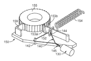
- FIG. 14 is a perspective view of a drive system of the infusion pump device of FIG. 13 .
- an infusion pump system 10 include a pump device 100 that can communicate with a controller device 200 .
- the pump device 100 includes a housing structure 110 that defines a cavity 116 in which a fluid cartridge 120 is received.
- the pump system 10 in a medical infusion pump system that is configured to controllably dispense a medicine from the cartridge 120 .
- the fluid cartridge 120 may contain a medicine to be infused into the tissue or vasculature of a targeted individual, such as a human or animal patient.
- the pump device 100 can be adapted to receive a medicine cartridge 120 in the form of carpule that is preloaded with insulin or another medicine for use in the treatment of Diabetes (e.g., Byetta®, Symlin®, or others).
- a medicine cartridge 120 may be supplied, for example, by Eli Lilly and Co. of Indianapolis, Ind.
- Other examples of medicines contained in the fluid cartridge 120 include: pain relief drugs, hormone therapy, blood pressure treatments, anti-emetics, osteoporosis treatments, or other injectable medicines.
- the pump device 100 includes a drive system that causes controlled dispensation of the medicine or other fluid from the cartridge 120 .
- the drive system (not shown in FIG. 1 ) incrementally advances a piston rod longitudinally into the cartridge 120 so that the fluid is forced out of the output end 122 (described below).
- the septum at the output end 122 can be pierced to permit fluid outflow when a cap member (not shown in FIG. 1 , refer to cap member 315 in FIG. 5 for one example) is connected to the pump housing structure 110 .
- the drive system may be housed in the housing structure 110 of the pump device in a compact manner so that the pump device 100 is portable, wearable, concealable, or a combination thereof.
- the overall length of the pump housing structure 110 (which contains medicine cartridge and the drive system) can be about 7 cm to about 9 cm (about 8.3 cm or less in this embodiment).
- the pump housing structure 110 may have an overall height of about 1.5 cm to about 4 cm (about 2.9 cm or less in this embodiment) and an overall thickness of about 8 mm to about 20 mm (about 14.5 mm or less in this embodiment).
- a user can conveniently wear the pump device 100 on the user's skin (e.g., skin adhesive) underneath the user's clothing or carry the pump device 100 in the user's pocket (or other portable location) while receiving the medicine dispensed from the pump device.
- skin e.g., skin adhesive
- the overall length of the pump housing structure 110 (which contains medicine cartridge and the drive system) can be about 7 cm to about 9 cm (about 8.3 cm or less in this embodiment).
- the pump housing structure 110 may have an overall height of about 1.5 cm to about 4 cm (about 2.9 cm or less in this embodiment) and an overall thickness of about 8 mm to about 20 mm (about 14.5 mm or less in this embodiment).
- the controller device 200 can be figured to mate with the compact pump housing structure 110 so that, when removably attached to one another, the components define a portable infusion pump unit that stores a relatively large quantity of medicine compared to the overall size of the unit.
- the infusion pump system 10 (including the pump device 100 attached to the removable controller device 200 ) may have an overall length of about 7 cm to about 9 cm (about 8.5 cm or less in this embodiment), an overall height of about 1.5 cm to about 4 cm (about 3.5 cm or less in this embodiment), and an overall thickness of about 8 mm to about 20 mm (about 15 mm or less in this embodiment).
- the drive system of the pump device 100 may be continuously or intermittently controlled by pump controller device 200 .
- the controller device 200 is configured to removably attach to the pump device 100 , When attached, the controller device 200 communicates electronic control signals via hard-wire-connection to the drive system or other components of the pump device 100 .
- the controller device 200 can include a controller housing structure 210 that is configured to mate with a complementary portion of the pump housing structure 110 so as to form a releasable mechanical connection.
- the pump housing structure 110 may define a cavity 118 that mates with a complementary protruding face (not show in FIG. 1 ) of the controller housing structure 210 for a friction fit engagement.
- the controller housing structure 210 may include a channel 212 that mates with a curved surface 117 of the pump housing structure 110 when the controller device 200 is attached to the pump device.
- one or more releasable connector devices e.g., mating tongues and grooves, mounting protrusions friction fit into mating cavities, or the like
- the pump device 100 may include one or more electrical contacts 118 that are exposed to the controller device 200 and that mate with opposing electrical contacts (e.g., conductive pads, pins, and the like) on the adjacent face of the controller device 200 .
- the controller device 200 is in electrical communication with the pump device 100 and is capable of transmitting electrical signals to the pump device 100 and receiving feedback signals (e.g., sensor signals) from components within the pump device 100 .
- the pump controller device 200 includes a user interface 220 that permits a user to monitor the operation of the pump device 100 .
- the user interface includes a display 222 and one or more user-selectable buttons 224 , 226 , and 228 .
- the display 222 may be used to communicate a number of settings or menu options for the infusion pump system 10 .
- the user may press one or more of the buttons 224 , 226 , and 228 to shuffle through a number of menus or program screens that show particular settings and data (e.g., review data that shows the medicine dispensing rate or the total amount of medicine dispensed in a given time period).
- the user can adjust the settings or otherwise program the controller device 200 by pressing one or more buttons 224 , 226 , and 228 of the user interface 220 .
- the user may press one or more of the buttons 224 , 226 , and 228 to change the dispensation rate of insulin or to request that a bolus of insulin be dispensed.
- the user interface 220 may include tactile buttons, a touch screen, audio inputs or outputs, or a combination thereof.
- Previously incorporated U.S. Provisional Application Ser. No. 60/721,267 also describes a number of configurations for a removable controller device in addition to the configuration illustrated in FIG. 1 herein.
- the controller device 200 when the controller device 200 is connected to the pump device 100 , the user is provided with the opportunity to readily monitor infusion pump operation by simply viewing the user interface 210 connected to the pump device 100 .
- Such monitoring capabilities may provide comfort to a user who may have urgent questions about the current operation of the pump device 100 (e.g., the user may be unable to receive immediate answers if wearing an infusion pump device having no user interface attached thereto).
- there is no need for the user to carry and operate a separate device to monitor the operation of the infusion pump device 100 thereby simplifying the monitoring process and reducing the number of devices that must be carried by the user.
- the pump device 100 includes a drive system 105 that accurately and incrementally dispenses fluid from the pump device 100 in a controlled manner.
- the pump housing structure 110 includes a detachable shell 112 that covers at least a portion of the drive system 105 and includes a frame portion 114 to which at least a portion of the drive system 105 is mounted.
- the detachable shell 112 may include an inner curved surface against which a curved section of a piston rod 170 rests.
- the frame portion 114 define a the cavity 116 that receives the fluid cartridge 120 .
- One or both of the detachable shell 112 and the frame portion 114 can be molded from polymer material, such as Polycarbonate, Acrylonitrile Butadiene Styrene, or Acrylic.
- the fluid cartridge 120 may occupy a majority of the length of the pump device 100 (with the drive system 105 being arranged in a compact manner) so that the pump device 100 is wearable and portable.
- the drive system 105 may include a rotational motor 130 that is coupled to a string member 140 , which is used to adjust a ratchet mechanism 150 .
- the rotational motor 130 can be used to act upon the string member 140 , thereby causing the string member 140 to adjust a pawl member 152 relative to a ratchet body 155 .
- the ratchet body 155 is in the form of a ratchet wheel.
- the ratchet wheel 155 can be integrally formed with, or mounted to, a worm gear 156 .
- Incremental rotation of the ratchet wheel 155 causes rotation of a drive wheel 160 (due to engagement with the worm gear 156 ), which causes the incremental longitudinal advancement of a flexible piston rod 170 .
- the piston rod 170 is advanced into plunger chamber 126 of the fluid cartridge 120 (e.g., defined in this embodiment by the circumferential wall 124 of the fluid cartridge 120 )
- the fluid in the cartridge 120 is forced from the septum at the output end 122 .
- the septum at the output end 122 may be pierced by a cap member (not shown in FIG.
- the drive system 105 can provide a reliable and compact configuration for accurately dispensing the desired volume of fluid from the pump device 100 .
- the drive system 105 may comprise few, if any, high-cost actuator components or electronics, thereby facilitating the relatively low-cost production of a disposable and reliable pump device 100 .
- the rotational motor 130 may comprise a battery powered actuator having a rotatable output shaft 132 .
- the rotational motor 130 can receive signals that cause the output shaft to rotate in a first rotational direction or in a second, opposite rotational direction.
- a suitable rotational motor 130 is a coreless DC motor supplied by Jinlong Machinery of China.
- the rotational motor 130 can be mounted to the frame portion 114 of the pump housing structure 110 so that the motor 130 remains in a substantially stationary position relative to the electrical contacts 119 of the pump device 100 .
- the operation of the rotational motor 130 can be controlled by the control device 200 ( FIG. 1 ) via electrical signals communicated through one or more of the electrical contacts 119 .
- one or more of the electrical contacts 119 may be directly connected to the inputs of the rotation motor 130 , for example, to deliver control signals from a control circuit or to deliver electrical current from a battery, capacitor, or other power source disposed in the controller device 200 or disposed in the pump device 100 .
- the electrical contacts 119 may be connected to an electrical circuit (e.g., an integrated circuit implemented on a small printed circuit board) onboard the pump device 100 (e.g., mounted to the frame portion 114 ).
- the control device 200 may deliver control signals via the electrical contacts 119 to the electrical circuit onboard the pump device 100 , which then opens a gate or a circuit pathway to permit the electrical current to pass to the rotational motor 130 (e.g., from a battery or other power source disposed in the pump device 100 ).
- the string member 140 may be coupled to the rotational motor 130 so that actuation by the motor 130 causes the string member 140 to act upon the ratchet mechanism 150 .
- one or more full rotations of the motor 130 can be translated into a tension force in the string member 140 that is applied to a pawl member 152 , which (in this embodiment) is pivotable to a reset position by the tension force from the string member 140 .
- the string member 140 is coupled between the rotational motor 130 and the ratchet mechanism 150 so as to provide a reliable and consistent adjustment of the ratchet mechanism 150 .
- the string member 140 may comprise a flexible member capable of transmitting a tension force, for example, a braided string structure (some examples are described below in connection with FIG. 3B ), a monofilament string structure, a flexible tape or ribbon structure, or the like.
- the string member 140 can be arranged in a loop around two or more guides (e.g., two guides 142 and 144 are shown in this embodiment). Such a loop arranged can be used to optimize the location and direction of the tension force in the string member 140 that is applied to the ratchet mechanism 150 . Moreover, the loop arrangement of the string member may provide a force amplification effect when the string member 140 is wound using the rotational motor 130 , which may permit the use of a smaller-sized motor in the pump design.
- Previously incorporated U.S. Provisional Application Ser. No. 60/720,411 also describes a number of loop arrangements for the string member 140 in addition to the illustrative example depicted in FIGS. 3A-C herein.
- the string member 140 starts at the shaft 132 of the rotational motor 130 , passes around a stationary guide 142 , around a second guide 144 connected to the pawl member 152 , and then back to the motor 130 to form a loop arrangement.
- the motor 130 spins such that a portion 145 the string member 140 winds upon itself, thus drawing the two guides 142 and 144 together with a force amplification effect.
- the string member 140 may comprise braided filaments that are capable of enduring repeated twisting sequences of the string member 140 .
- the braided filaments may comprise one or more polymer materials, such as PET (e.g., DTex Dyneema material available from Honeywell, Inc.).
- PET e.g., DTex Dyneema material available from Honeywell, Inc.
- Such braided filament string members are capable of enduring the torsion and frictional forces associated with undergoing thousands of cycles of twisting as described above in connection with FIGS. 2 and 3A .
- the string member 140 can be formed to have an outer diameter of about 0.02 mm to about 0.07 mm, and preferably about 0.05 mm.
- the string member 140 may comprise braided filaments that are arranged around a centrally disposed thin wire filament having a diameter of about 0.02 mm or less.
- the thin wire filament may comprise a polymer material a metallic material having a non-coarse outer surface. Such materials may also be capable of enduring the repeated twisting sequences of the string member 140 . Such a construction may permit the outer filament surfaces to frictionally engage one another during the twisting process while the filament surfaces contacting the centrally disposed thin wire are exposed to a reduced friction load.
- the string member 140 is coupled to the ratchet mechanism 150 , which provides incremental motion to thereby advance the piston rod 170 .
- the ratchet mechanism 150 includes the pawl member 152 and the ratchet body 155 , which in this embodiment is a ratchet wheel having a number of teeth along its circumferential surface.
- the pawl member that is adjustable between a reset position and a forward position.
- the rotational motor 130 may be activated to twist the string member 140 (as previously described), and the string member 140 then applies a tension force that adjusts the pawl member 152 to the reset position where the pawl member 152 engages one or more new teeth of the ratchet wheel 155 .
- a spring device 154 is also coupled to the pawl member so as to urge the pawl member 152 toward the forward position. This spring bias causes the pawl member 152 to drive the ratchet wheel 155 an incremental amount in a forward rotational direction as the string member 140 is untwisted.
- the adjustable pawl member 152 is constructed in such a way as to engage the teeth of the ratchet wheel 155 in a single direction (e.g., in the forward rotational direction of the ratchet wheel 155 ).
- a locking pawl 159 prevents the ratchet wheel 155 from reverse motion.
- the adjustable pawl member 152 can adjust from the forward position to the reset position (shown in FIG. 3A ) to engage a new tooth of the ratchet wheel 155 while the ratchet wheel 155 remains in position due to the locking pawl 159 .
- the adjustable pawl member 152 is pivotably coupled to a support plate 151 at so that the string member 140 and the spring device 154 can act to pivot the pawl member between the reset position and the forward position.
- a first end portion of the pawl member 152 may be fixedly or hingedly mounted to the support plate 151 while a free end portion of the pawl member 152 engages the ratchet wheel 155 .
- the locking pawl 159 is fixedly coupled to the support plate 151 .
- the ratchet mechanism 150 can employ a set of stopper pins 153 a and 153 b that limit the motion of the adjustable pawl member 152 .
- the stopper pins 153 a and 153 b can serve as location sensors to detect when the pawl member 152 has reached the reset position (e.g., adjacent the stopper pin 153 a ) or the forward position (e.g., adjacent the stopper pin 153 b ).
- these sensors can be optical, magnetic, or contact type sensors.
- the sensors may be capable of transmitting signals that indicate when the location of the pawl member 152 is detected. Such sensor signals may be transmitted to the motor 130 , to the controller device 200 ( FIG. 1 ), or a combination thereof.
- a signal can indicate that the pawl member 152 has reached the limit of its travel and the motor 130 will cease rotation in that direction (e.g., end the twisting process on the string member 140 in that direction).
- the driving force of the ratchet mechanism 150 can be provided by energy stored in a potential energy storage device, such as the spring device 154 .
- a potential energy storage device such as the spring device 154 .
- the potential energy of the spring device 154 is being translated to kinetic energy for the motion of the pawl member 152 and the ratchet wheel 155 .
- the pawl member 152 may start at the reset position (as shown in FIG. 3A ) with the string member 140 in a twisted configuration.
- the controller device 200 FIG.
- the rotational motor 130 may begin to rotate in a first rotational direction that unwinds the string member 140 , thereby permitting the spring device 154 to drive the pawl member 152 toward the forward position.
- the rotational motor 130 continues to rotate in the first direction so that after the pawl member 152 reaches the forward position (e.g., adjacent the stopper pin 153 b ), the string member 140 begins to twist in the opposite orientation.
- Such twisting of the string member 140 causes a tension force that overcomes the bias of the spring device 154 and adjusts the pawl member 152 toward the reset position.
- the rotational motor 130 stops rotating in the first rotational direction and the pawl member 152 remains at rest in the reset position.
- the rotational motor 130 would begin the cycle by rotating in a second rotational direction (opposite the first rotational direction) so as to unwind the string member 140 yet again. This pattern of cycles may continue until the piston rod 170 has reached the limit of its longitudinal travel (described in more detail below).
- the incremental motion cycle may begin with the pawl member 152 starting at the forward position (e.g., adjacent the stopper pin 153 b ).
- the rotation motor 130 would rotate in a first rotational direction to twist the string until the pawl member is moved to the reset position (as shown in FIG. 3A ), and then the rotational motor 130 would rotate in a second, opposite rotational direction to unwind the string member 140 until the pawl member 152 returns to the forward position.
- the spring device 154 can be coupled to the pawl member 152 at a first end portion and coupled to the support plate 151 at a second end portion.
- the spring device 154 can be to the pawl member 152 at a first end portion and coupled to a part of the frame portion 114 (not directly joined to the support plate 151 ).
- the ratchet wheel 155 can be coupled with a worm gear 156 so that the incremental rotation of the ratchet wheel 155 is translated to the worm gear 156 .
- Such rotation of the worm gear 156 causes a rotation of a drive wheel 160 , which is rotatably mounted to the frame portion 114 of the pump device 100 .
- the drive wheel 160 includes a central aperture having an internal thread pattern therein (not shown in FIG. 2 ).
- the internal thread pattern of the drive wheel 160 mates is an external thread pattern on the flexible piston rod 170 so that the piston rod 170 is longitudinally advanced inside the plunger chamber 126 of the fluid cartridge 120 .
- the incremental motion of provided by the ratchet mechanism 150 , the string member 140 , and the motor 130 causes the drive wheel 160 to incrementally rotate, which in turn translates to a longitudinal advancement of the flexible piston rod 170 .
- the drive system 105 can advance the piston rod 170 an increment of about 16 microns or less (about 4 microns to about 12 microns, and preferably about 7 microns to about 8 microns) for each incremental motion cycle of the motor 130 , string member 140 , and ratchet mechanism 150 as previously described.
- the flexible piston rod 170 comprises a plurality of segments 172 serially connected by hinge portions so that the flexible piston rod 170 is adjustable from a curved shape to a noncurved shape.
- the plurality of segments 172 and the interconnecting hinge portions can be integrally formed in one piece from a moldable material, including a number of polymer materials such as Nylon or POM.
- the plurality of segments 172 comprise generally cylindrical segments that each include an exterior thread pattern along at least one cylindrical surface portion.
- a plunger connector 178 may be coupled to the leading end of the flexible piston rod 170 so as to abut against the plunger (not shown in FIG. 2 ) in the plunger chamber 126 of the fluid cartridge 120 .
- the flexible piston rod 170 can include an anti-rotation structure that hinders the piston rod 170 from rotating with drive wheel 160 (thereby allowing the rotation of the drive wheel 160 to translate into a longitudinal motion of the piston rod 170 ).
- the flexible piston 170 includes a longitudinal channel 173 extending through each of the segments 172 .
- the longitudinal channel 173 can engage a complementary protrusion on the frame portion 114 (not shown in FIG. 2 ) proximate the drive wheel 160 so that the flexible piston rod 170 is hindered from rotating when the drive wheel 160 turns relative to the frame portion 114 .
- the longitudinal channel in each segment 172 aligns to form a keyway that receives a mating key (e.g., a protrusion) on the frame portion 114 .
- the anti-rotation structure may include a plurality of longitudinal channels 173 (with each channel capable of engaging an associated protrusion that acts as a key to hinder rotation while permitting longitudinal motion), one or more flat surfaces along each segment 172 (with the flat surface slidably engaging a complementary flat surface on the frame portion 114 ), or the like.
- the flexible piston rod 170 is in a retracted state so that it has a generally curved shape, with some or all of the cylindrical segments 172 hinged away from the adjacent segments 172 . As the rod segments 172 are advanced through the drive wheel 160 , the segments 172 abut one another end-to-end so as to form a generally rigid, noncurved shape.
- Previously incorporated U.S. Provisional Application Ser. No. 60/720,405 also describes a number of configurations for the flexible piston rod 170 in addition to the configuration illustrated in FIG. 2 herein.
- the flexible piston rod 170 is adjustable from a curved shape to a noncurved shape, the overall length of the pump device can be reduced in some embodiments.
- the typical infusion pump requires a package or housing having a linear dimension sufficient to accommodate the length of the rigid piston rod when it is at its limit of travel in which it is fully withdrawn from the container or cylinder. This requirement for a large linear dimension can make it difficult to make the overall size of the typical infusion pump small enough for certain desired applications, such as, for example, wearable or implantable pumps.
- L 2 t+y, (1)
- L is the minimum overall linear dimension or length required to support the driven member part of the device
- t is the required linear travel of an equivalent rigid driven member
- y is an added sum for the space required to support the driving member part of the device.
- the space requirement of pump device 100 having the flexible piston rod 170 is substantially less than the space requirement of a similar device actuated by a rigid piston rod. This can be explained by referencing the original “space requirement” equation set forth above as Equation (1).
- L is the minimum overall linear dimension or length required to support the driven member part of the device
- t is the required travel of the flexible driven member (flexible pushrod)
- y is an added sum for the space required to support the driving member
- z is the space required to house the unused portion of the flexible driving member.
- the space required under component “z’ is a function of the properties of the flexible piston rod 170 (e.g., the curved portion of the flexible piston rod 170 before it is advanced toward the fluid cartridge 120 ).
- the pump device 100 incorporating the flexible piston rod 170 would require less space than the same device if it were to incorporate a non-flexible, rigid rod.
- the overall length of the pump housing structure 110 can be less than twice the push rod travel length.
- the flexible piston rod 170 may include segments that have a shape other than the generally cylindrical segments 172 .
- the segments of the flexible piston rod 170 can have a generally a square or rectangular cross-section (rather than a cylindrical shape), with teeth or a thread pattern on at least one surface thereof.
- the flexible piston rod 170 may pass through a carrier in which the drive wheel 160 is rotatably mounted.
- the drive wheel 160 can have a threaded edge, that engages the teeth of the rod segments.
- rotation of the drive wheel 160 causes a linear advancement of the flexible piston rod 170 along an axis that is parallel to the axis of rotation of the drive wheel 160 , while the passage of the rod segments through the carrier aligns the segments into a linear orientation.
- the drive system 305 can include a string member 340 in a loop arrangement around more than two guides, such as four guide structures 342 , 344 , 346 , and 348 .
- the motion path of the string member 340 and the orientation of the string member 340 can be configured to provide an efficient mechanical advantage orientation during the desired motion of the adjustable pawl member 352 .
- One of the guide structures 348 may be coupled to the adjustable pawl member 352 while the remaining guide structures 342 , 344 , and 346 are coupled to the frame portion 314 of the pump device 314 .
- the string member 340 may have a loop configuration with more directional changes compared to the embodiments previously described in connection with FIGS. 2 and 3A .
- the pump device 300 includes a housing structure 310 that defines a cavity 316 capable of receiving a fluid cartridge 320 .
- the housing structure 310 may include a frame portion 314 and a detachable shell portion 312 (refer to FIG. 5 ) so that, when assembled, the pump device 300 can have an outer configuration that mates with a removable controller device 390 (refer to FIGS. 6-7 ).
- the drive system 305 can be contained in the housing structure 310 of the pump device 300 in a compact manner so that the pump device 300 is portable, wearable, concealable, or a combination thereof.
- a user can conveniently wear the pump device 300 on the user's skin (e.g., skin adhesive) underneath the user's clothing or carry the pump device 100 in the user's pocket (or another portable location) while receiving the medicine dispensed from the pump device 300 .
- skin e.g., skin adhesive
- the pump device 300 can be part of an infusion pump system 20 in which the pump device 300 communicates with a controller device, including but not limited to the removable controller device 390 depicted in FIGS. 6-7 .
- the controller device 390 includes a user interface 391 so that the operation of the pump device 300 can be readily monitored by a user.
- the user interface 391 may include a display 392 and two or more buttons (e.g., two buttons 394 a and 394 b are provided in this embodiment).
- the pump system 20 can be a medical infusion pump system that is configured to controllably dispense a medicine from the cartridge 320 .
- the pump device 300 can be adapted to receive a medicine cartridge 320 in the form of a preloaded carpule that contains insulin or another medicine for use in the treatment of Diabetes (e.g., Byetta®, Symlin®, or others) or other injectable medicines.
- the pump device 300 includes a drive system 305 that causes controlled dispensation of the medicine or other fluid from the cartridge 320 .
- the drive system 305 may incrementally advance a flexible piston rod 370 into a plunger chamber 326 of the cartridge 320 so that the fluid is force out the septum at the output end 322 .
- the controller device 390 can communicate control signals to the drive system 305 or other components of the pump device 300 .
- the controller device 390 can include a controller housing structure that is configured to mate with a complementary portion of the pump housing structure 310 so as to form a mechanical connection.
- the controller housing structure may include a cavity that mates with a portion of the pump housing structure 310 when the controller device 390 is attached to the pump device 300 .
- the controller device 390 may include a flexible finger 317 to mate with an complementary surface of the pump housing structure 310 . Further, as shown for example in FIG.
- the pump device 300 may include one or more magnetically attractable devices 318 a and 318 b that engage with complementary magnetically attractable devices of the controller device 390 (not shown in FIGS. 6-7 ). As such, the magnetically attractable devices 318 a and 318 b may contribute to releasably secure the pump device 300 to the controller device 390 .
- Other mechanical connectors e.g., snap-fit connectors, magnetic connectors, surface protrusions that mate with female cavities, or the like
- the pump device 300 may include on or more electrical contacts 319 that are exposed to the controller device 390 and that mate with opposing electrical contacts (e.g., pads, pins, or the like) on the adjacent face of the controller device 390 .
- the electrical contacts 319 are disposed on the detachable shell portion 312 of the pump housing structure 310 (refer to FIG. 5 ) and are aligned with an electrical contact device 309 mounted in the frame portion 314 . It should be understood that, in other embodiments, the electrical contacts 319 may be arranged on the frame portion 314 rather than on the detachable shell portion 312 .
- the frame portion 314 of the pump device may define a space 315 (refer to FIG. 4 ) that is capable of receiving a connection circuit 306 (refer to FIG. 5 ).
- the connection circuit 306 may be simple and inexpensive so as to facilitate a low-cost pump device 300 that is disposable.
- the connection circuit 306 may include a battery 307 or other power source and, optionally, a gateway circuit device 308 . In some circumstances, the gateway circuit device 308 may be under the control of and directed by the control circuit in the controller device 390 .
- the connection circuit 306 provides the electrical contact device 309 so as to facilitate electrical communication with the removable controller device 390 .
- the controller device 390 capable of transmitting electrical signals to the pump device 300 and is capable of receiving feedback signals (e.g., sensor signals) from the components in the pump device 300 .
- the gateway circuit device 308 of the circuit 309 may be in electrical communication (e.g., via one or more electrical wires or electrically conductive traces) with a force sensor 377 (refer to FIG. 8 ) arranged between the plunger connector 378 that the plunger 321 .
- the force sensor 377 may comprise a force transducer or load cell that is capable of electrically communicating an applied force.
- the force sensor 377 can provide feedback signals to the circuit 309 (or to the control device 390 via the electrical contacts) so as to monitor the force transmitted to the plunger 321 of the medicine cartridge 320 .
- Such information can be used, for example, to detect if an occlusion exists in the medicine flow path.
- Other sensors e.g., a pressure sensor, a flow sensor, a rotation sensor, a displacement sensor, or the like
- the connection circuit 306 may be configured to operate without the gateway circuit device 308 .
- control circuit in the removable controller device 390 may communicate via the electrical contacts directly with a portion of the drive system 305 (e.g., direct electrical communication with the motor 330 ), with one or more sensors disposed in the pump device 300 , and with the battery 307 .
- the pump device 300 includes a drive system 305 that is capable of accurately and incrementally dispensing fluid from the fluid cartridge 320 in a controlled manner.
- the drive system 305 may include the rotational motor 330 that is coupled to the string member 340 .
- the rotational motor 330 can be used to act upon the string member 340 , thereby causing the string member 340 to adjust a pawl member 352 relative to a ratchet body 355 .
- the ratchet body 355 is in the form of a ratchet wheel that is integrally formed with a worm gear 356 .
- Incremental rotation of the ratchet wheel 355 causes rotation of a drive wheel 360 , which causes the incremental longitudinal advancement of a flexible piston rod 370 .
- the piston rod 370 is advanced into plunger chamber 326 (e.g., defined in this embodiment by the circumferential wall 324 of the fluid cartridge 320 )
- the fluid in the cartridge 320 is forced from septum at the output end 322 .
- the septum at the output end 322 may be pierced by a cap member 315 mounted to the housing structure 310 , which can provide fluid communication from the cartridge 320 to an infusion set tube attached to the patient.
- the cap member 315 may include a penetrator device 316 a that provides fluid communication from the medicine cartridge 320 to a tube connection end 316 b .
- the drive system 305 can provide a reliable and compact configuration for accurately dispensing the desired volume of fluid from the pump device 300 .
- the drive system 305 may comprise few, if any, high-cost actuator components or electronics, thereby facilitating the production of a disposable and reliable pump device 300 . (It should be understood that FIG. 5 depicts the drive system 305 mounted to the frame portion 314 of the pump device 300 , and FIG. 8 shows a similar view with the frame portion 314 removed for purposes of illustrating the drive system 305 and the fluid cartridge 320 .)
- some components of the drive system 305 can be retained by the frame portion 314 , a cover mount 311 that is assembled to the frame portion 314 , or a combination thereof.
- the rotational motor 330 , the string member 340 , and the spring device 354 can be assembled into the frame portion 314 and then retained by the cover mount 311 .
- the adjustable pawl member 352 , the ratchet wheel 355 , and the worm gear 356 can be assembled onto and axle 351 that is integrally formed with the frame portion 314 and then retained by the cover mount 311 .
- a locking pawl 359 can be integrally formed with the frame portion 314 so as to align with the ratchet wheel 355 when the ratchet wheel 355 is assembled onto the axle 351 .
- the drive wheel 360 and an adjacent bearing 365 can be received in annular channels 363 and 367 , respectively, of the frame portion 314 .
- the cover mount 311 When the cover mount 311 is assembled to the frame portion 314 , the cover mount 311 can restrict the radial or axial movement of the drive wheel 360 while permitting forward rotation of the drive wheel 360 .
- the “unused” or retracted portion of the piston rod 370 may rest in a channel 313 defined in the top of the cover mount 311 .
- the cover mount 311 and the frame portion 314 can collectively permit the desired motion of the components of the drive system 305 while reducing the likelihood of “backlash” movement or component dislodgement (which might otherwise occur, for example, when the pump device 300 is dropped to the ground).
- the rotational motor 330 may comprise an electrically power actuator having a rotatable output shaft 332 .
- the rotational motor 330 can receive signals that cause the output shaft to rotate in a first rotational direction or in a second, opposite rotational direction.
- a suitable rotational motor 330 is a coreless DC motor supplied by Jinlong Machinery of China.
- the operation of the rotational motor 330 can be controlled by a control device (e.g., removable control device 200 as described in connection with FIG. 1 or the like) via electrical signals communicated through one or more electrical contacts.
- the string member 340 may be coupled to the rotational motor 330 so that actuation by the motor 330 causes the string member to act upon the ratchet mechanism 350 .
- One or more full rotations of the motor 330 can be translated into a tension force in the string member 340 that is applied to a pawl member 352 , which (in this embodiment) is pivoted to a reset position by the tension force from the string member 140 .
- the string member 340 is coupled between the rotational motor 330 and the ratchet mechanism 350 so as to provide a reliable and consistent adjustment of the ratchet mechanism 350 .
- the string member 340 is coupled to the motor shaft 332 using a mechanical connector 333 .
- the string member 140 may comprise a flexible member capable of transmitting a tension force, for example, a braided string structure, a monofilament string structure, a flexible tape or ribbon structure, or the like.
- the string member 340 can be arranged in a loop around two or more guide structures (e.g., four guide structures 342 , 344 , 346 , and 348 are shown in this embodiment).
- the motion path of the string member 340 and the orientation of the string member 340 can be configured to provide an efficient mechanical advantage orientation during the desired motion of the adjustable pawl member 352 .
- one of the guide structures 348 is coupled to the adjustable pawl member 352 while the remaining guide structures 342 , 344 , and 346 are integrally formed with the frame portion 314 of the pump device 300 (guide structures 342 , 344 , and 346 are shown in dotted lines to represent their location on the frame portion 314 (not shown in FIGS. 9-10 )).
- the guide structure 346 exemplifies how a single guide structure can have two sliding surfaces that oppose one another, thereby functioning similar to a configuration having two different guides.
- the loop arrangement of the string member 340 may provide a force amplification effect when the string member 340 is wound using the rotational motor 330 .
- the string member 340 starts at the shaft 332 of the rotational motor 330 , passes around a first sliding surface of the guide structure 346 , around a second guide structure 342 , around a third guide structure 348 connected to the adjustable pawl member 352 , around a fourth guide structure 344 , around a second sliding surface of the guide structure 346 , and then back to the motor 330 to form the loop arrangement.
- the motor 330 rotates, a portion 345 the string member 340 twists upon itself, thus drawing the guide structure 348 toward the stationary guide structures 342 and 344 .
- the orientation of the stationary guide structures 342 and 344 relative to the guide structure 348 (connected to the pawl member 352 ) can be configured to provide an efficient mechanical advantage for the tension force applied by the string member 340 during the desired motion of the adjustable pawl member 352 .
- the string member 340 is coupled to the ratchet mechanism 350 , which provides incremental motion to thereby advance the piston rod 370 .
- the ratchet mechanism 350 includes the pawl member 352 and the ratchet body 355 , which in this embodiment is a ratchet wheel having a number of teeth along its circumferential surface.
- the pawl member 352 is adjustable between a reset position (refer to FIG. 10 ) and a forward position (refer to FIG. 9 ).
- the rotational motor 330 may be activated to twist the string member 340 , and the string member 340 then applies a tension force that adjusts the pawl member 352 to the reset position in which the pawl member 352 grabs a new tooth of the ratchet wheel 335 (refer to FIG. 10 ).
- the adjustable pawl member 352 is pivotably coupled to about the axis of the axle 351 (refer to FIG. 4 ) that receives the ratchet wheel 355 and the worm gear 356 .
- a spring device 354 is also coupled to the pawl member 352 so as to urge the pawl member 352 toward the forward position (refer to FIG. 9 ).
- the spring device 354 is in the form of a leaf spring that is fixed to the frame portion 314 (refer to FIG. 4 ) at a first end portion and that is engaged with an abutment protrusion 357 of the pawl member 352 at a second end portion.
- the spring device 354 is flexed and stores potential energy that urges the pawl member 152 to return to the forward position (refer to FIG.
- a locking pawl 359 coupled to the frame portion 314 prevents the ratchet wheel 355 from reverse motion.
- the adjustable pawl member 352 can adjust from the forward position (refer to FIG. 9 ) to the reset position (refer to FIG. 10 ) to engage a new tooth of the ratchet wheel 355 while the ratchet wheel 355 remains in position due to the locking pawl 359 .
- the drive system 305 can employ a set of stopper pins (similar to previously described embodiments) that limit the motion of the adjustable pawl member 352 or that serve as location sensors to indicate when the pawl member 352 has reach the reset position or the forward position.
- these sensors can be optical, magnetic, or contact type sensors.
- the sensors may be capable of transmitting signals that indicate when the location of the guide structure 348 or the pawl member 352 is detected. Such sensor signals may be transmitted to the motor 330 , to the controller device, or a combination thereof.
- the ratchet wheel 355 can be integrally formed with the worm gear 356 so that the incremental rotation of the ratchet wheel 355 is translated to the worm gear 356 .
- Such rotation of the worm gear 356 causes a rotation of a drive wheel 360 , which is rotatably mounted to the frame portion 314 of the pump device 300 .
- the drive wheel 360 includes a central aperture having an internal thread pattern therein (not shown in FIGS. 9-10 ), which mates is an external thread pattern on the flexible piston rod 370 .
- the incremental motion provided by the ratchet mechanism 350 , the string member 340 , and the motor 330 causes the drive wheel 360 to incrementally rotate, which in turn translates to a linear advancement of the flexible piston rod 370 .
- the piston rod 370 may undergo only forward or positive displacement as a result of drive system 305 .
- the drive system 305 substantially hinders the piston rod 370 from retracting or “backing up” in response to fluid pressure in the medicine cartridge 320 or other reversal forces.
- the flexible piston rod 370 can be retracted only upon disassembly of the pump device 300 (e.g., to disengage the gears or the ratchet mechanism).
- the non-retractable piston rod configuration (due to the drive system 305 ) may facilitate a “one time use” disposable pump device, thereby reducing the likelihood of failure due to non-intended repeated use of the disposable pump device.
- the flexible piston rod 370 comprises a plurality of segments 372 serially connected by hinge portions so that the flexible piston rod 370 is adjustable from a curved shape to a noncurved shape.
- the plurality of segments 372 and the interconnecting hinge portions can be integrally formed in one piece from a moldable material, including one or more polymer materials such as Nylon or POM.
- the plurality of segments 372 comprise generally cylindrical segments that each include an exterior thread pattern along at least one cylindrical surface portion.
- a plunger connector 378 may be coupled to the leading end of the flexible piston rod 370 so as to abut against or connect with the plunger 321 in the plunger chamber 326 of the fluid cartridge 320 .
- Previously incorporated U.S. Provisional Application Ser. No. 60/720,405 also describes a number of configurations for the flexible piston rod 370 in addition to the configuration illustrated in FIGS. 9-10 herein.
- the incremental motion cycle of the drive system 305 may include rotation of the motor 330 so that the string member 340 transitions from a twisted state, to an untwisted state, and then again to a twisted state. Such a transition of the string member 340 can cause the pawl member 352 to adjust from the reset position (refer to FIG. 11A ), to the forward position (refer to FIG. 11B ), and back to the reset position (refer to FIG. 11C ).
- the adjustment of the pawl member 352 from the reset position to the forward position drives the ratchet wheel 355 and worm gear 356 , which incrementally rotates the drive wheel 360 and thereby advances the flexible piston rod 370 a longitudinal increment distance 379 (refer to FIG. 11B ).
- the drive system 305 can advance the piston rod 370 a longitudinal increment distance 379 of about 16 microns or less (about 4 microns to about 12 microns, and preferably about 7 microns to about 8 microns) for each incremental motion cycle of the motor 330 , string member 340 , and ratchet mechanism 350 as previously described herein.
- some embodiments of the motor 330 may include a mandrel 334 extending axially from the mechanical connector 333 or the motor shaft 332 .
- the mandrel can be arranged so that the string member 340 is configured to twist around the mandrel 334 in response to rotation by the motor shaft 332 .
- the frictional wear upon the string material may be reduced because the string member engages and twists around the mandrel 334 rather than engaging an opposing string material surface and twisting upon itself.
- the pawl member 352 begins at the reset position with the string member 340 in a twisted configuration at string portion 345 .
- the string portion 345 is twisted around the mandrel 334 that extends axially from the motor 330 .
- the adjustable pawl member 352 is in the reset position as shown in FIG. 11A , it is capable of engaging a tooth of the ratchet wheel 355 .
- the rotational motor 330 may begin to rotate in a first rotational direction that unwinds the string member 340 , thereby permitting the spring device 354 to drive the pawl member 352 toward the forward position (refer to FIG. 11B ).
- the adjustable pawl 352 is driving the ratchet wheel 355 in the forward rotational direction
- the potential energy of the spring device 354 is being translated to kinetic energy for the motion of the pawl member 352 and the ratchet wheel 355 .
- Such an adjustment of the pawl member 352 from the reset position to the forward position drives the ratchet wheel 355 and the integrally formed worm gear 356 .
- the incremental rotation of the worm gear 356 results in an incremental rotation by the drive wheel 360 , which advances the flexible piston rod 370 the longitudinal increment distance 379 .
- Such an incremental advancement of the flexible piston rod 370 may cause a predetermined volume of fluid to be dispensed from the cartridge 320 ( FIG. 4 ).
- the rotational motor 330 continues to rotate in the first rotational direction so that after the pawl member 352 reaches the forward position, the string member 340 begins to twist in the opposite orientation.
- the string member 340 is twisted around the mandrel 334 that extends axially from the motor 330 .
- Such twisting of the string member 340 causes a tension force that overcomes the bias of the spring device 354 and adjusts the pawl member 352 toward the reset position.
- the adjustable pawl member 352 reaches the reset position, as shown in FIG. 11C , the pawl member is capable of engaging a new tooth of the ratchet wheel 355 .
- the locking pawl 359 (shown in FIG.
- the rotational motor 330 would begin the cycle by rotating in a second rotational direction (opposite the first rotational direction) so as to unwind the string member 340 yet again. This pattern of cycles may continue until the piston rod 370 has reached the limit of its longitudinal travel.
- the incremental motion cycle may begin with the pawl member 352 starting at the forward position (refer to FIG. 11B ).
- the rotation motor 330 would rotate in a first rotational direction to twist the string until the pawl member is moved to the reset position (refer to FIG. 11C ), and then the rotational motor 330 would rotate in a second, opposite rotational direction to unwind the string member 340 until the pawl member 352 returns to the forward position (refer again to FIG. 11B ).
- the string member 340 may comprise braided filaments that are capable of enduring repeated twisting sequences of the string member 340 .
- the braided filaments may comprise a polymer such as PET.
- Such braided filament string members are capable of enduring the torsion and frictional forces associated with undergoing thousands of cycles of twisting as described above in connection with FIGS. 11A-C .
- the string member 340 can be formed to have an outer diameter of about 0.02 mm to about 0.07 mm, and preferably about 0.05 mm.
- the string member 340 may comprise braided filaments that are arranged around a centrally disposed thin wire filament (e.g., comprising a polymer material or a metallic material) having a diameter of about 0.02 mm or less, which is also capable of enduring the repeated twisting sequences of the string member 340 .
- a centrally disposed thin wire filament e.g., comprising a polymer material or a metallic material
- Such a construction may permit the outer filament surfaces to frictionally engage one another during the twisting process while the filament surfaces contacting the centrally disposed thin wire are exposed to a reduced friction load.
- a pump device 400 can include a string member and a rotational motor like the previously described embodiments, except that the string member 440 is configured to wind (or unwind or both) around a spindle device.
- the string member 440 is configured to wind (or unwind or both) around a spindle device.
- Such a configuration may reduce the torsion and friction loads upon the string member material while providing a tension force to adjust the ratchet mechanism.
- the spindle configuration may further reduce the space requirements for drive system in the pump housing, thereby providing a reliable and compact infusion pump system that is portable and wearable by the user.
- a ratchet mechanism 450 that is configured to assemble within a pump device (similar to the ratchet mechanism 150 in pump device 100 described in connection with FIG. 3A ) is adjusted by a string member 440 that can wind around a spindle device 442 .
- the ratchet mechanism 450 , string member 440 , spindle device 442 , and motor 430 can be part of a drive system for the pump device (similar to the drive system 105 of the pump device 100 described in connection with FIG. 2 ) that provides a reliable and consistent configuration for accurately dispensing the desired volume of fluid from the infusion pump device.
- the drive system including the string member 440 , the motor 430 , and the spindle device 442 may comprise few, if any, high-cost components, thereby facilitating the production of a disposable infusion pump device.
- the pump device may house the drive system in a compact manner, the pump device can be portable, wearable, and readily concealable by the user.
- the spindle device 442 can be coupled to a rotational motor 430 so that the spindle device 442 rotates with the motor shaft.
- a string member 440 can be attached to the spindle device 442 so that the string member 440 winds or unwinds around the spindle device 442 in response to the rotation of the motor 430 .
- the string member 440 may comprise a flexible member capable of transmitting a tension force, for example, a braided filament structure, a monofilament string structure, a flexible tape or ribbon structure, or the like.
- the string member 440 may comprise a flexible tape material having generally flat opposing surfaces, thereby permitting the tape material to be wrapped around itself when being wound on the spindle device 442 .
- the string member 440 is also coupled to the ratchet mechanism 450 , which provides incremental motion to thereby advance the piston rod (not shown in FIG. 12 ).
- the ratchet mechanism 450 includes the pawl member 452 and the ratchet body 455 , which in this embodiment is a ratchet wheel having a number of teeth along its circumferential surface.
- the pawl member 452 is adjustable between a reset position (refer to FIG. 12 ) and a forward position.
- the rotational motor 430 may be activated to rotate the spindle device 442 and thereby wind the string member 440 (as previously described), and the string member 440 then applies a tension force that adjusts the pawl member 452 to the reset position.
- the pawl member 452 can engage one or more new teeth of the ratchet wheel 455 .
- a spring device 454 is also coupled to the pawl member 452 so as to urge the pawl member 452 toward the forward position. This spring force causes the pawl member 452 to drive the ratchet wheel 455 an incremental amount in a forward rotational direction.
- a locking pawl 459 prevents the ratchet wheel 455 from reverse motion.
- the adjustable pawl member 452 can adjust from the forward position to the reset position (shown in FIG. 12 ) to engage a new tooth of the ratchet wheel 455 while the ratchet wheel 455 remains in position due to the locking pawl 459 .
- the ratchet mechanism 450 can employ a set of stopper pins (as previously described) that limit the motion of the adjustable pawl member 452 .
- the stopper pins can serve as location sensors to detect when the pawl member has reach the reset position or the forward position.
- these sensors can be optical, magnetic, or contact type sensors.
- the pawl member 452 may start at the reset position (as shown in FIG. 12 ) with the string member 440 wound around the spindle device 442 .
- the rotational motor 430 may begin to rotate in a first rotational direction that unwinds the string member 440 from the spindle device 442 , thereby permitting the spring device 454 to force the pawl member 452 toward the forward position.
- the rotational motor 430 continues to rotate in the first rotational direction so that after the pawl member 452 reaches the forward position, the string member 440 begins to wind around the spindle device 442 in the opposite orientation.
- Such winding of the string member 440 causes a tension force that overcomes the bias of the spring device 454 and adjusts the pawl member 452 toward the reset position.
- the rotational motor 430 stops rotating in the first rotational direction and the pawl member 452 remains at rest in the reset position.
- the rotational motor 430 would begin the cycle by rotating in a second rotational direction (opposite the first rotational direction) so as to unwind the string member 440 from the spindle device 442 yet again.
- the incremental motion cycle may begin with the pawl member 452 starting at the forward position.
- the rotational motor 430 would rotate in a first rotational direction to wind the string member 440 around the spindle device until the pawl member 452 is moved to the reset position (as shown in FIG. 12 ), and then the rotational motor 430 would rotate in a second, opposite rotational direction to unwind the string member 440 from the spindle device 442 until the pawl member 452 returns to the forward position.
- the drive system 505 can include a string member 540 that is configured to wrapped around a spindle device 542 .
- the orientation of the string member 540 can be configured to provide an efficient mechanical advantage during the desired motion of the adjustable pawl member 552 .
- such a configuration may reduce the torsion and friction loads upon the string member material and may further reduce the space requirements for drive system 505 of the pump device 500 .
- the string member 540 may comprise a flexible member capable of transmitting a tension force, for example, a braided filament structure, a monofilament string structure, a flexible tape or ribbon structure, or the like.
- the string member 540 may comprise a flexible tape material having generally flat opposing surfaces, thereby permitting the tape material to be wrapped around itself when being wound on the spindle device 542 .
- the pump device 500 includes a housing structure 510 that defines a cavity 516 capable of receiving a fluid cartridge (not shown in FIGS. 13-14 ).
- the housing structure 510 may include a frame portion 514 and a detachable shell portion (removed from FIGS. 13-14 for purposes of illustration) so that, when assembled, the pump device 500 can have an outer appearance similar to that of pump device 300 depicted in FIG. 5 .
- the drive system 505 can be contained in the housing structure 510 of the pump device 500 in a compact manner so that the pump device 500 is portable, wearable, concealable, or a combination thereof.
- the pump device 500 can be part of an infusion pump system in which the pump device communicates with a controller device, including but not limited to the removable controller device 390 described in connection with FIGS. 5-7 .
- the controller device can communicate control signals to the drive system 505 or other components of the pump device 500 .
- the pump device 500 may include on or more electrical contacts that are exposed to the controller device and that mate with opposing electrical contacts (e.g., pads, pins, or the like) on the adjacent end of the controller device.
- the pump system is a medical infusion pump system that is configured to controllably dispense a medicine.
- the pump device 500 can be adapted to receive a medicine cartridge in the form of carpule that contains insulin or another medicament for use in the treatment of Diabetes (e.g., exenatide, ByettaTM, or others), or other injectable medicines.
- the pump device 500 includes a drive system 505 that is capable of accurately and incrementally dispensing fluid from the fluid cartridge in a controlled manner.
- the drive system 505 may include a rotational motor 530 that is coupled to a string member 540 .
- the rotational motor 530 can be used to wind (or unwind or both) the string member 540 around a spindle device 542 , which causes the string member 540 to adjust a pawl member 552 relative to a ratchet body 555 .
- the ratchet body 555 is in the form of a ratchet wheel that is integrally formed with a worm gear 556 .
- Incremental rotation of the ratchet wheel 555 causes rotation of a drive wheel 560 , which causes the incremental linear advancement of a flexible piston rod 570 .
- the drive system 505 can provide a reliable and compact configuration for accurately dispensing the desired volume of fluid from the pump device 500 .
- the drive system 505 may comprise few, if any, high-cost actuator components or electronics, thereby facilitating the production of a disposable and reliable pump device 500 .
- the string member 540 is coupled to the ratchet mechanism, which provides incremental motion to thereby advance the piston rod 570 .
- the ratchet mechanism includes the pawl member 552 and the ratchet body 555 , which in this embodiment is a ratchet wheel having a number of teeth along its circumferential surface.
- the pawl member 552 is adjustable between a reset position and a forward position (refer to FIG. 14 ).
- the rotational motor 530 may be activated to wind the string member 540 around the spindle device 542 , and the string member 540 then applies a tension force that adjusts the pawl member 552 to the reset position in which the pawl member 552 grabs a new tooth of the ratchet wheel 555 .
- a spring device 554 is also coupled to the pawl member 552 so as to urge the pawl member 552 toward the forward position.
- the spring device 554 is a leaf spring that is fixed to the frame portion 514 (refer to FIG. 13 ) at a first end portion and that is engaged with an abutment protrusion 557 of the pawl member 552 at a second end portion.
- the spring device 554 when the pawl member 552 is adjusted to the reset position, the spring device 554 is increasingly flexed and thereby stores potential energy that urges the pawl member 552 to return to the forward position.
- a locking pawl coupled to the frame portion 514 prevents the ratchet wheel 555 from reverse motion.
- the adjustable pawl member 552 can adjust from the forward position to the reset position to engage a new tooth of the ratchet wheel 555 while the ratchet wheel 555 remains in position due to the locking pawl 559 .
- the ratchet wheel 555 is integrally formed with the worm gear 556 so that the incremental rotation of the ratchet wheel 555 is translated to the worm gear 556 .
- Such rotation of the worm gear 556 causes a rotation of a drive wheel 560 , which is rotatably mounted to the frame portion 514 using a bearing 565 .
- the drive wheel 560 includes a central aperture having an internal thread pattern therein (not shown in FIGS. 13-14 ), which mates with an external thread pattern on the flexible piston rod 570 .
- a plunger connector 578 may be coupled to the leading end of the flexible piston rod 570 so as to abut against or connect with the plunger in the fluid cartridge.
- the incremental motion cycle of the drive system 505 may include rotation of the motor 530 so that the string member 540 transitions from a wrapped state (e.g., wound around the spindle device 542 ), to an unwrapped state, and then to a wrapped state.
- a transition of the string member 540 can cause the adjustable pawl member 552 to transition from the reset position, to the forward position (refer to FIG. 14 ), and back to the reset position.
- the adjustment of the pawl member 552 from the reset position to the forward position drives the incremental rotation of the drive wheel 560 , which advances the flexible piston rod 570 a longitudinal increment distance.
- the drive system 505 can advance the piston rod 570 a longitudinal increment distance of about 16 microns or less (about 4 microns to about 12 microns, and preferably about 7 microns to about 8 microns) for each incremental motion cycle of the motor 530 , string member 540 , and ratchet mechanism 550 as previously described herein. It should be understood, that in other embodiments, the incremental motion cycle may begin with the pawl member 552 starting at the forward position (refer to FIG. 14 ).
- the rotation motor 530 would rotate in a first rotational direction to wind the string member 540 around the spindle device 542 until the pawl member 552 is moved to the reset position, and then the rotational motor 530 would rotate in a second, opposite rotational direction to unwind the string member 540 until the pawl member 552 returns to the forward position.
Landscapes
- Health & Medical Sciences (AREA)
- Vascular Medicine (AREA)
- Engineering & Computer Science (AREA)
- Anesthesiology (AREA)
- Biomedical Technology (AREA)
- Heart & Thoracic Surgery (AREA)
- Hematology (AREA)
- Life Sciences & Earth Sciences (AREA)
- Animal Behavior & Ethology (AREA)
- General Health & Medical Sciences (AREA)
- Public Health (AREA)
- Veterinary Medicine (AREA)
- Infusion, Injection, And Reservoir Apparatuses (AREA)
Abstract
Description
F(string)=T(motor)/r(string),
where T(motor) is the torque rating of the motor, r(string) is the radius of the string and F(string) is the subsequent pulling force on the string. To find the total force upon the guide coupled to the pawl (F(guide)):
F(guide)=F(string)+F(String)cos(θ)−L(friction)
or reducing
F(guide)=T(motor)/r(string)[1+cos(θ)]−L(friction),
where cos(θ) describes the angle of the string with respect to parallel to the axis of the stationary guide and the drive guide and L(friction) represents the total losses associated with friction within the system.
L=2t+y, (1)
where:
“L” is the minimum overall linear dimension or length required to support the driven member part of the device;
“t” is the required linear travel of an equivalent rigid driven member; and
“y” is an added sum for the space required to support the driving member part of the device.
L=t+y+z, (2)
where:
“L” is the minimum overall linear dimension or length required to support the driven member part of the device;
“t” is the required travel of the flexible driven member (flexible pushrod);
“y” is an added sum for the space required to support the driving member; and
“z” is the space required to house the unused portion of the flexible driving member.
Claims (9)
Priority Applications (2)
| Application Number | Priority Date | Filing Date | Title |
|---|---|---|---|
| US13/936,684 US9814830B2 (en) | 2005-09-26 | 2013-07-08 | Dispensing fluid from an infusion pump system |
| US15/783,322 US10603431B2 (en) | 2005-09-26 | 2017-10-13 | Dispensing fluid from an infusion pump system |
Applications Claiming Priority (8)
| Application Number | Priority Date | Filing Date | Title |
|---|---|---|---|
| US72040505P | 2005-09-26 | 2005-09-26 | |
| US72041105P | 2005-09-26 | 2005-09-26 | |
| US72126705P | 2005-09-28 | 2005-09-28 | |
| US11/522,560 US7534226B2 (en) | 2005-09-26 | 2006-09-18 | Dispensing fluid from an infusion pump system |
| US12/422,711 US7938803B2 (en) | 2005-09-26 | 2009-04-13 | Dispensing fluid from an infusion pump system |
| US13/070,569 US8282601B2 (en) | 2005-09-26 | 2011-03-24 | Dispensing fluid from an infusion pump system |
| US13/616,303 US8480623B2 (en) | 2005-09-26 | 2012-09-14 | Method for dispensing fluid from an infusion pump system |
| US13/936,684 US9814830B2 (en) | 2005-09-26 | 2013-07-08 | Dispensing fluid from an infusion pump system |
Related Parent Applications (1)
| Application Number | Title | Priority Date | Filing Date |
|---|---|---|---|
| US13/616,303 Continuation US8480623B2 (en) | 2005-09-26 | 2012-09-14 | Method for dispensing fluid from an infusion pump system |
Related Child Applications (1)
| Application Number | Title | Priority Date | Filing Date |
|---|---|---|---|
| US15/783,322 Continuation US10603431B2 (en) | 2005-09-26 | 2017-10-13 | Dispensing fluid from an infusion pump system |
Publications (2)
| Publication Number | Publication Date |
|---|---|
| US20130296789A1 US20130296789A1 (en) | 2013-11-07 |
| US9814830B2 true US9814830B2 (en) | 2017-11-14 |
Family
ID=37895089
Family Applications (7)
| Application Number | Title | Priority Date | Filing Date |
|---|---|---|---|
| US11/522,560 Expired - Fee Related US7534226B2 (en) | 2005-09-26 | 2006-09-18 | Dispensing fluid from an infusion pump system |
| US12/422,711 Active 2026-10-03 US7938803B2 (en) | 2005-09-26 | 2009-04-13 | Dispensing fluid from an infusion pump system |
| US13/070,569 Active US8282601B2 (en) | 2005-09-26 | 2011-03-24 | Dispensing fluid from an infusion pump system |
| US13/616,303 Active US8480623B2 (en) | 2005-09-26 | 2012-09-14 | Method for dispensing fluid from an infusion pump system |
| US13/936,684 Active 2028-08-04 US9814830B2 (en) | 2005-09-26 | 2013-07-08 | Dispensing fluid from an infusion pump system |
| US14/035,119 Active 2027-08-04 US9314569B2 (en) | 2005-09-26 | 2013-09-24 | Dispensing fluid from an infusion pump system |
| US15/783,322 Active 2027-04-28 US10603431B2 (en) | 2005-09-26 | 2017-10-13 | Dispensing fluid from an infusion pump system |
Family Applications Before (4)
| Application Number | Title | Priority Date | Filing Date |
|---|---|---|---|
| US11/522,560 Expired - Fee Related US7534226B2 (en) | 2005-09-26 | 2006-09-18 | Dispensing fluid from an infusion pump system |
| US12/422,711 Active 2026-10-03 US7938803B2 (en) | 2005-09-26 | 2009-04-13 | Dispensing fluid from an infusion pump system |
| US13/070,569 Active US8282601B2 (en) | 2005-09-26 | 2011-03-24 | Dispensing fluid from an infusion pump system |
| US13/616,303 Active US8480623B2 (en) | 2005-09-26 | 2012-09-14 | Method for dispensing fluid from an infusion pump system |
Family Applications After (2)
| Application Number | Title | Priority Date | Filing Date |
|---|---|---|---|
| US14/035,119 Active 2027-08-04 US9314569B2 (en) | 2005-09-26 | 2013-09-24 | Dispensing fluid from an infusion pump system |
| US15/783,322 Active 2027-04-28 US10603431B2 (en) | 2005-09-26 | 2017-10-13 | Dispensing fluid from an infusion pump system |
Country Status (1)
| Country | Link |
|---|---|
| US (7) | US7534226B2 (en) |
Cited By (14)
| Publication number | Priority date | Publication date | Assignee | Title |
|---|---|---|---|---|
| US10857287B2 (en) | 2017-01-06 | 2020-12-08 | Trustees Of Boston University | Infusion system and components thereof |
| US10881789B2 (en) | 2013-10-24 | 2021-01-05 | Trustees Of Boston University | Infusion system for preventing mischanneling of multiple medicaments |
| US11278661B2 (en) | 2020-03-10 | 2022-03-22 | Beta Bionics, Inc. | Infusion system and components thereof |
| US11311674B2 (en) | 2016-01-21 | 2022-04-26 | West Pharma. Services IL, Ltd. | Medicament delivery device comprising a visual indicator |
| US11318254B2 (en) | 2015-10-09 | 2022-05-03 | West Pharma. Services IL, Ltd. | Injector needle cap remover |
| US11331463B2 (en) | 2015-07-08 | 2022-05-17 | Trustees Of Boston University | Infusion system and components thereof |
| US11338090B2 (en) | 2016-08-01 | 2022-05-24 | West Pharma. Services IL, Ltd. | Anti-rotation cartridge pin |
| US11364337B2 (en) | 2016-01-21 | 2022-06-21 | West Pharma. Services IL, Ltd. | Force containment in an automatic injector |
| US11389597B2 (en) | 2016-03-16 | 2022-07-19 | West Pharma. Services IL, Ltd. | Staged telescopic screw assembly having different visual indicators |
| US11504481B2 (en) | 2007-10-02 | 2022-11-22 | West Pharma. Services IL, Ltd. | Anti-rotation feature for infusion pump cartridge |
| US11547802B2 (en) | 2015-10-09 | 2023-01-10 | West Pharma. Services IL, Ltd. | Angled syringe patch injector |
| US11571507B2 (en) | 2019-07-16 | 2023-02-07 | Beta Bionics, Inc. | Ambulatory device and components thereof |
| US11672904B2 (en) | 2016-01-21 | 2023-06-13 | West Pharma. Services IL, Ltd. | Needle insertion and retraction mechanism |
| US11819666B2 (en) | 2017-05-30 | 2023-11-21 | West Pharma. Services IL, Ltd. | Modular drive train for wearable injector |
Families Citing this family (206)
| Publication number | Priority date | Publication date | Assignee | Title |
|---|---|---|---|---|
| US6852104B2 (en) | 2002-02-28 | 2005-02-08 | Smiths Medical Md, Inc. | Programmable insulin pump |
| US20050160858A1 (en) * | 2002-07-24 | 2005-07-28 | M 2 Medical A/S | Shape memory alloy actuator |
| AU2003245872A1 (en) | 2002-07-24 | 2004-02-09 | M 2 Medical A/S | An infusion pump system, an infusion pump unit and an infusion pump |
| WO2004041330A2 (en) | 2002-11-05 | 2004-05-21 | M 2 Medical A/S | A disposable wearable insulin dispensing device, a combination of such a device and a programming controller and a method of controlling the operation of such a device |
| AU2003287926A1 (en) * | 2002-12-23 | 2004-07-14 | M2 Medical A/S | A disposable, wearable insulin dispensing device, a combination of such a device and a programming controller and a method of controlling the operation of such a device |
| WO2004056411A2 (en) * | 2002-12-23 | 2004-07-08 | M 2 Medical A/S | Flexible piston rod |
| ES2737835T3 (en) | 2003-04-23 | 2020-01-16 | Valeritas Inc | Hydraulically driven pump for long-term medication administration |
| JP4509100B2 (en) * | 2003-05-08 | 2010-07-21 | ノボ・ノルデイスク・エー/エス | Infusion device attachable to skin with removable needle insertion actuation |
| ATE392223T1 (en) * | 2003-05-08 | 2008-05-15 | Novo Nordisk As | INTERNAL NEEDLE INTRODUCER |
| EP1475113A1 (en) * | 2003-05-08 | 2004-11-10 | Novo Nordisk A/S | External needle inserter |
| EP1502613A1 (en) * | 2003-08-01 | 2005-02-02 | Novo Nordisk A/S | Needle device with retraction means |
| KR20060099520A (en) * | 2003-10-21 | 2006-09-19 | 노보 노르디스크 에이/에스 | Medical skin mountable device |
| US7753879B2 (en) * | 2004-01-29 | 2010-07-13 | M2 Group Holdings, Inc. | Disposable medicine dispensing device |
| CN100586495C (en) * | 2004-03-30 | 2010-02-03 | 诺和诺德公司 | Actuator system comprising lever mechanism |
| KR20060131945A (en) * | 2004-03-30 | 2006-12-20 | 노보 노르디스크 에이/에스 | Actuator system comprising detection means |
| WO2006014425A1 (en) | 2004-07-02 | 2006-02-09 | Biovalve Technologies, Inc. | Methods and devices for delivering glp-1 and uses thereof |
| CN101027095B (en) * | 2004-09-22 | 2010-09-29 | 诺和诺德公司 | Medical device with cannula inserter |
| US20090012472A1 (en) * | 2004-09-22 | 2009-01-08 | Novo Nordisk A/S | Medical Device with Cannula Inserter |
| EP1824536B1 (en) * | 2004-12-06 | 2009-08-26 | Novo Nordisk A/S | Ventilated skin mountable device |
| JP2008528086A (en) | 2005-01-24 | 2008-07-31 | ノボ・ノルデイスク・エー/エス | Medical device with protected puncture device |
| WO2006105794A1 (en) | 2005-04-06 | 2006-10-12 | M 2 Medical A/S | An actuator |
| WO2006120253A2 (en) * | 2005-05-13 | 2006-11-16 | Novo Nordisk A/S | Medical device adapted to detect disengagement of a transcutaneous device |
| US8551046B2 (en) | 2006-09-18 | 2013-10-08 | Asante Solutions, Inc. | Dispensing fluid from an infusion pump system |
| US8409142B2 (en) | 2005-09-26 | 2013-04-02 | Asante Solutions, Inc. | Operating an infusion pump system |
| WO2007038059A2 (en) * | 2005-09-26 | 2007-04-05 | M2 Medical A/S | Infusion pump with a drive having a ratchet and pawl combination |
| US7534226B2 (en) | 2005-09-26 | 2009-05-19 | M2 Group Holdings, Inc. | Dispensing fluid from an infusion pump system |
| US8057436B2 (en) * | 2005-09-26 | 2011-11-15 | Asante Solutions, Inc. | Dispensing fluid from an infusion pump system |
| US8105279B2 (en) | 2005-09-26 | 2012-01-31 | M2 Group Holdings, Inc. | Dispensing fluid from an infusion pump system |
| WO2007056504A1 (en) * | 2005-11-08 | 2007-05-18 | M2 Medical A/S | Infusion pump system |
| WO2007056592A2 (en) | 2005-11-08 | 2007-05-18 | M2 Medical A/S | Method and system for manual and autonomous control of an infusion pump |
| US9173992B2 (en) * | 2006-03-13 | 2015-11-03 | Novo Nordisk A/S | Secure pairing of electronic devices using dual means of communication |
| CN101401314B (en) * | 2006-03-13 | 2013-04-24 | 诺沃-诺迪斯克有限公司 | Medical system comprising dual purpose communication means |
| JP2009532117A (en) | 2006-03-30 | 2009-09-10 | ヴァレリタス,エルエルシー | Multi-cartridge fluid dispensing device |
| EP2012852A1 (en) * | 2006-04-26 | 2009-01-14 | Novo Nordisk A/S | Skin-mountable device in packaging comprising coated seal member |
| DE102006024051A1 (en) * | 2006-05-23 | 2007-12-06 | Eppendorf Ag | Electronic dosing device for dosing liquids |
| WO2007141210A1 (en) * | 2006-06-06 | 2007-12-13 | Novo Nordisk A/S | Assembly comprising skin-mountable device and packaging therefore |
| US20100063448A1 (en) * | 2007-03-06 | 2010-03-11 | Novo Nordisk A/S | Pump assembly comprising actuator system |
| US20080228056A1 (en) | 2007-03-13 | 2008-09-18 | Michael Blomquist | Basal rate testing using frequent blood glucose input |
| US7892199B2 (en) | 2007-05-21 | 2011-02-22 | Asante Solutions, Inc. | Occlusion sensing for an infusion pump |
| US7794426B2 (en) | 2007-05-21 | 2010-09-14 | Asante Solutions, Inc. | Infusion pump system with contamination-resistant features |
| US7981102B2 (en) * | 2007-05-21 | 2011-07-19 | Asante Solutions, Inc. | Removable controller for an infusion pump |
| US7833196B2 (en) * | 2007-05-21 | 2010-11-16 | Asante Solutions, Inc. | Illumination instrument for an infusion pump |
| US7751907B2 (en) | 2007-05-24 | 2010-07-06 | Smiths Medical Asd, Inc. | Expert system for insulin pump therapy |
| US8221345B2 (en) | 2007-05-30 | 2012-07-17 | Smiths Medical Asd, Inc. | Insulin pump based expert system |
| US7828528B2 (en) * | 2007-09-06 | 2010-11-09 | Asante Solutions, Inc. | Occlusion sensing system for infusion pumps |
| US7717903B2 (en) | 2007-09-06 | 2010-05-18 | M2 Group Holdings, Inc. | Operating an infusion pump system |
| US7935076B2 (en) | 2007-09-07 | 2011-05-03 | Asante Solutions, Inc. | Activity sensing techniques for an infusion pump system |
| US7935105B2 (en) * | 2007-09-07 | 2011-05-03 | Asante Solutions, Inc. | Data storage for an infusion pump system |
| US8287514B2 (en) | 2007-09-07 | 2012-10-16 | Asante Solutions, Inc. | Power management techniques for an infusion pump system |
| US7879026B2 (en) | 2007-09-07 | 2011-02-01 | Asante Solutions, Inc. | Controlled adjustment of medicine dispensation from an infusion pump device |
| US8062008B2 (en) * | 2007-09-27 | 2011-11-22 | Curlin Medical Inc. | Peristaltic pump and removable cassette therefor |
| US7934912B2 (en) * | 2007-09-27 | 2011-05-03 | Curlin Medical Inc | Peristaltic pump assembly with cassette and mounting pin arrangement |
| US8083503B2 (en) * | 2007-09-27 | 2011-12-27 | Curlin Medical Inc. | Peristaltic pump assembly and regulator therefor |
| US9656019B2 (en) | 2007-10-02 | 2017-05-23 | Medimop Medical Projects Ltd. | Apparatuses for securing components of a drug delivery system during transport and methods of using same |
| US10420880B2 (en) | 2007-10-02 | 2019-09-24 | West Pharma. Services IL, Ltd. | Key for securing components of a drug delivery system during assembly and/or transport and methods of using same |
| US7967795B1 (en) | 2010-01-19 | 2011-06-28 | Lamodel Ltd. | Cartridge interface assembly with driving plunger |
| US9345836B2 (en) | 2007-10-02 | 2016-05-24 | Medimop Medical Projects Ltd. | Disengagement resistant telescoping assembly and unidirectional method of assembly for such |
| CN101888859B (en) * | 2007-10-31 | 2014-09-17 | 诺沃-诺迪斯克有限公司 | Non-porous material as sterilization barrier |
| US7875022B2 (en) * | 2007-12-12 | 2011-01-25 | Asante Solutions, Inc. | Portable infusion pump and media player |
| US8986253B2 (en) | 2008-01-25 | 2015-03-24 | Tandem Diabetes Care, Inc. | Two chamber pumps and related methods |
| US8234126B1 (en) | 2008-02-12 | 2012-07-31 | Asante Solutions, Inc. | Distribution of infusion pumps |
| US7938797B2 (en) * | 2008-05-05 | 2011-05-10 | Asante Solutions, Inc. | Infusion pump system |
| US8052645B2 (en) | 2008-07-23 | 2011-11-08 | Avant Medical Corp. | System and method for an injection using a syringe needle |
| CA2724641C (en) | 2008-05-20 | 2020-03-24 | Avant Medical Corp. | Autoinjector system |
| US7959598B2 (en) * | 2008-08-20 | 2011-06-14 | Asante Solutions, Inc. | Infusion pump systems and methods |
| US9393369B2 (en) | 2008-09-15 | 2016-07-19 | Medimop Medical Projects Ltd. | Stabilized pen injector |
| US8408421B2 (en) | 2008-09-16 | 2013-04-02 | Tandem Diabetes Care, Inc. | Flow regulating stopcocks and related methods |
| US8650937B2 (en) | 2008-09-19 | 2014-02-18 | Tandem Diabetes Care, Inc. | Solute concentration measurement device and related methods |
| US8287487B2 (en) | 2008-10-15 | 2012-10-16 | Asante Solutions, Inc. | Infusion pump system and methods |
| US8105269B2 (en) | 2008-10-24 | 2012-01-31 | Baxter International Inc. | In situ tubing measurements for infusion pumps |
| US8152779B2 (en) | 2008-12-30 | 2012-04-10 | Medimop Medical Projects Ltd. | Needle assembly for drug pump |
| US8974439B2 (en) * | 2009-01-02 | 2015-03-10 | Asante Solutions, Inc. | Infusion pump system and methods |
| US20100217233A1 (en) * | 2009-02-20 | 2010-08-26 | Ranft Elizabeth A | Method and device to anesthetize an area |
| US8137083B2 (en) | 2009-03-11 | 2012-03-20 | Baxter International Inc. | Infusion pump actuators, system and method for controlling medical fluid flowrate |
| DE102009017693A1 (en) | 2009-04-15 | 2010-05-20 | Innovent E.V. Technologieentwicklung | Method for finishing or impregnating wood utilized for forming wooden musical instrument, involves making wood to be processed to contact urea solution, and treating wood at low pressure and/or temperature in aqueous urea solution |
| CN101987220B (en) * | 2009-07-30 | 2013-11-13 | 德昌电机(深圳)有限公司 | Needle driving assembly for medical instrument |
| EP2724739B1 (en) | 2009-07-30 | 2015-07-01 | Tandem Diabetes Care, Inc. | Portable infusion pump system |
| US10071198B2 (en) | 2012-11-02 | 2018-09-11 | West Pharma. Servicees IL, Ltd. | Adhesive structure for medical device |
| US8157769B2 (en) | 2009-09-15 | 2012-04-17 | Medimop Medical Projects Ltd. | Cartridge insertion assembly for drug delivery system |
| US10071196B2 (en) | 2012-05-15 | 2018-09-11 | West Pharma. Services IL, Ltd. | Method for selectively powering a battery-operated drug-delivery device and device therefor |
| WO2011063279A1 (en) | 2009-11-19 | 2011-05-26 | Knee Creations, Llc | Coordinate mapping system for joint treatment |
| US8951261B2 (en) * | 2009-11-20 | 2015-02-10 | Zimmer Knee Creations, Inc. | Subchondral treatment of joint pain |
| US8821504B2 (en) | 2009-11-20 | 2014-09-02 | Zimmer Knee Creations, Inc. | Method for treating joint pain and associated instruments |
| JP2013511358A (en) | 2009-11-20 | 2013-04-04 | ニー・クリエイションズ・リミテッド・ライアビリティ・カンパニー | Navigation and positioning equipment for joint repair |
| WO2011063257A1 (en) | 2009-11-20 | 2011-05-26 | Knee Creations, Llc | Instruments for targeting a joint defect |
| US8608802B2 (en) | 2009-11-20 | 2013-12-17 | Zimmer Knee Creations, Inc. | Implantable devices for subchondral treatment of joint pain |
| AU2010321822A1 (en) | 2009-11-20 | 2012-07-12 | Knee Creations, Llc | Instruments for a variable angle approach to a joint |
| WO2011063260A1 (en) | 2009-11-20 | 2011-05-26 | Knee Creations, Llc | Bone-derived implantable devices for subchondral treatment of joint pain |
| US8882701B2 (en) | 2009-12-04 | 2014-11-11 | Smiths Medical Asd, Inc. | Advanced step therapy delivery for an ambulatory infusion pump and system |
| TWI415644B (en) * | 2009-12-14 | 2013-11-21 | Shl Group Ab | Medicament delivery device |
| US8382447B2 (en) | 2009-12-31 | 2013-02-26 | Baxter International, Inc. | Shuttle pump with controlled geometry |
| US8348898B2 (en) | 2010-01-19 | 2013-01-08 | Medimop Medical Projects Ltd. | Automatic needle for drug pump |
| EP2569031B1 (en) | 2010-05-10 | 2017-10-11 | Medimop Medical Projects Ltd. | Low volume accurate injector |
| USD669165S1 (en) * | 2010-05-27 | 2012-10-16 | Asante Solutions, Inc. | Infusion pump |
| USD669167S1 (en) * | 2010-05-27 | 2012-10-16 | Asante Solutions, Inc. | Controller for an infusion pump |
| USD669166S1 (en) * | 2010-05-27 | 2012-10-16 | Asante Solutions, Inc. | Infusion pump unit |
| GB2481066A (en) * | 2010-06-11 | 2011-12-14 | Britannia Pharmaceuticals Ltd | Portable case for infusion |
| US8567235B2 (en) | 2010-06-29 | 2013-10-29 | Baxter International Inc. | Tube measurement technique using linear actuator and pressure sensor |
| US8915879B2 (en) | 2010-09-24 | 2014-12-23 | Perqflo, Llc | Infusion pumps |
| US9498573B2 (en) | 2010-09-24 | 2016-11-22 | Perqflo, Llc | Infusion pumps |
| US9216249B2 (en) | 2010-09-24 | 2015-12-22 | Perqflo, Llc | Infusion pumps |
| US9381300B2 (en) | 2010-09-24 | 2016-07-05 | Perqflo, Llc | Infusion pumps |
| US8905972B2 (en) | 2010-11-20 | 2014-12-09 | Perqflo, Llc | Infusion pumps |
| US8852152B2 (en) | 2011-02-09 | 2014-10-07 | Asante Solutions, Inc. | Infusion pump systems and methods |
| USD702834S1 (en) | 2011-03-22 | 2014-04-15 | Medimop Medical Projects Ltd. | Cartridge for use in injection device |
| LT2699293T (en) | 2011-04-20 | 2019-04-25 | Amgen Inc. | Autoinjector apparatus |
| US8333716B1 (en) | 2011-06-21 | 2012-12-18 | Yofimeter, Llc | Methods for using an analyte testing device |
| US20130085349A1 (en) | 2011-06-21 | 2013-04-04 | Yofimeter, Llc | Analyte testing devices |
| US8585657B2 (en) | 2011-06-21 | 2013-11-19 | Asante Solutions, Inc. | Dispensing fluid from an infusion pump system |
| MX349916B (en) | 2011-09-02 | 2017-08-18 | Unitract Syringe Pty Ltd | Drive mechanism for drug delivery pumps with integrated status indication. |
| US11173244B2 (en) | 2011-09-02 | 2021-11-16 | Unl Holdings Llc | Drive mechanism for drug delivery pumps with integrated status indication |
| US9707335B2 (en) | 2011-09-02 | 2017-07-18 | Unitract Syringe Pty Ltd | Drive mechanism for drug delivery pumps with integrated status indication |
| US9814832B2 (en) | 2011-09-02 | 2017-11-14 | Unl Holdings Llc | Drive mechanism for drug delivery pumps with integrated status indication |
| US8808230B2 (en) | 2011-09-07 | 2014-08-19 | Asante Solutions, Inc. | Occlusion detection for an infusion pump system |
| EP2799101B1 (en) * | 2011-12-26 | 2019-09-11 | PHC Holdings Corporation | Pharmaceutical injection device |
| EP2809375B1 (en) | 2012-01-31 | 2021-08-11 | Medimop Medical Projects Ltd. | Time dependent drug delivery apparatus |
| US9463280B2 (en) | 2012-03-26 | 2016-10-11 | Medimop Medical Projects Ltd. | Motion activated septum puncturing drug delivery device |
| US10668213B2 (en) | 2012-03-26 | 2020-06-02 | West Pharma. Services IL, Ltd. | Motion activated mechanisms for a drug delivery device |
| US9072827B2 (en) | 2012-03-26 | 2015-07-07 | Medimop Medical Projects Ltd. | Fail safe point protector for needle safety flap |
| US9180242B2 (en) | 2012-05-17 | 2015-11-10 | Tandem Diabetes Care, Inc. | Methods and devices for multiple fluid transfer |
| US9555186B2 (en) | 2012-06-05 | 2017-01-31 | Tandem Diabetes Care, Inc. | Infusion pump system with disposable cartridge having pressure venting and pressure feedback |
| CN104619595B (en) | 2012-07-05 | 2017-08-22 | P.C.O.A.设备有限公司 | Pill dispenser |
| US8454557B1 (en) | 2012-07-19 | 2013-06-04 | Asante Solutions, Inc. | Infusion pump system and method |
| US8454562B1 (en) | 2012-07-20 | 2013-06-04 | Asante Solutions, Inc. | Infusion pump system and method |
| EP3284700B1 (en) | 2012-07-30 | 2019-06-05 | Dosentrx Ltd. | A receptacle for containing and dispensing solid medicinal pills |
| WO2014036239A2 (en) * | 2012-08-29 | 2014-03-06 | Unitract Syringe Pty Ltd | Controlled delivery drive mechanisms for drug delivery pumps |
| WO2014046950A1 (en) | 2012-09-24 | 2014-03-27 | Enable Injections, Llc | Medication vial and injector assemblies and methods of use |
| US9901677B2 (en) | 2012-10-16 | 2018-02-27 | Bigfoot Biomedical, Inc. | Infusion pump system and methods |
| US9574646B1 (en) * | 2012-10-25 | 2017-02-21 | Redwood Robotics Inc. | Twisted string transmission |
| US9427523B2 (en) | 2012-12-10 | 2016-08-30 | Bigfoot Biomedical, Inc. | Infusion pump system and method |
| US20140276536A1 (en) | 2013-03-14 | 2014-09-18 | Asante Solutions, Inc. | Infusion Pump System and Methods |
| US9421323B2 (en) | 2013-01-03 | 2016-08-23 | Medimop Medical Projects Ltd. | Door and doorstop for portable one use drug delivery apparatus |
| CN103110989B (en) * | 2013-02-25 | 2016-03-23 | 郭永风 | A kind of reciprocal aspirator of Compact structural and breast pump |
| US9446186B2 (en) | 2013-03-01 | 2016-09-20 | Bigfoot Biomedical, Inc. | Operating an infusion pump system |
| US9173998B2 (en) | 2013-03-14 | 2015-11-03 | Tandem Diabetes Care, Inc. | System and method for detecting occlusions in an infusion pump |
| US9421329B2 (en) | 2013-03-15 | 2016-08-23 | Tandem Diabetes Care, Inc. | Infusion device occlusion detection system |
| US10492990B2 (en) | 2013-03-15 | 2019-12-03 | Amgen Inc. | Drug cassette, autoinjector, and autoinjector system |
| US9011164B2 (en) | 2013-04-30 | 2015-04-21 | Medimop Medical Projects Ltd. | Clip contact for easy installation of printed circuit board PCB |
| US9889256B2 (en) | 2013-05-03 | 2018-02-13 | Medimop Medical Projects Ltd. | Sensing a status of an infuser based on sensing motor control and power input |
| US9457141B2 (en) | 2013-06-03 | 2016-10-04 | Bigfoot Biomedical, Inc. | Infusion pump system and method |
| US9446187B2 (en) | 2013-06-03 | 2016-09-20 | Bigfoot Biomedical, Inc. | Infusion pump system and method |
| HUE059908T2 (en) | 2013-06-18 | 2023-01-28 | Enable Injections Inc | Vial transfer and injection apparatus and method |
| US9561324B2 (en) | 2013-07-19 | 2017-02-07 | Bigfoot Biomedical, Inc. | Infusion pump system and method |
| EP3062865B1 (en) | 2013-11-01 | 2022-05-25 | Becton, Dickinson and Company | Injection device configured to mate with a mobile device |
| US10569015B2 (en) | 2013-12-02 | 2020-02-25 | Bigfoot Biomedical, Inc. | Infusion pump system and method |
| US9737656B2 (en) | 2013-12-26 | 2017-08-22 | Tandem Diabetes Care, Inc. | Integration of infusion pump with remote electronic device |
| US10279106B1 (en) | 2014-05-08 | 2019-05-07 | Tandem Diabetes Care, Inc. | Insulin patch pump |
| IL233295B (en) | 2014-06-22 | 2019-11-28 | Ilan Paz | A controlled pill-dispensing system |
| US9629901B2 (en) | 2014-07-01 | 2017-04-25 | Bigfoot Biomedical, Inc. | Glucagon administration system and methods |
| US11185627B2 (en) | 2014-07-21 | 2021-11-30 | Medtronic Minimed, Inc. | Smart connection interface |
| US10137246B2 (en) | 2014-08-06 | 2018-11-27 | Bigfoot Biomedical, Inc. | Infusion pump assembly and method |
| US9919096B2 (en) | 2014-08-26 | 2018-03-20 | Bigfoot Biomedical, Inc. | Infusion pump system and method |
| US10159786B2 (en) | 2014-09-30 | 2018-12-25 | Perqflo, Llc | Hybrid ambulatory infusion pumps |
| US10773028B2 (en) * | 2014-10-07 | 2020-09-15 | Silgan Dispensing Systems Corporation | Indexing dose dispensing device |
| JP6722192B2 (en) * | 2014-12-08 | 2020-07-15 | サノフイSanofi | Drive mechanism for use in a drug delivery device |
| CN106924881B (en) * | 2015-01-01 | 2018-12-25 | 文文 | A kind of safe and practical osteoporosis treatment instrument |
| WO2016133789A2 (en) | 2015-02-18 | 2016-08-25 | Perqflo, Llc | Ambulatory infusion pump and reservoir assemblies for use with same |
| US9795534B2 (en) | 2015-03-04 | 2017-10-24 | Medimop Medical Projects Ltd. | Compliant coupling assembly for cartridge coupling of a drug delivery device |
| US10251813B2 (en) | 2015-03-04 | 2019-04-09 | West Pharma. Services IL, Ltd. | Flexibly mounted cartridge alignment collar for drug delivery device |
| EP3067082A1 (en) * | 2015-03-13 | 2016-09-14 | Carebay Europe Ltd. | Motorized drug delivery device |
| USD959695S1 (en) * | 2015-04-01 | 2022-08-02 | Novartis Ag | Container for pharmaceuticals |
| US10293120B2 (en) | 2015-04-10 | 2019-05-21 | West Pharma. Services IL, Ltd. | Redundant injection device status indication |
| US9744297B2 (en) | 2015-04-10 | 2017-08-29 | Medimop Medical Projects Ltd. | Needle cannula position as an input to operational control of an injection device |
| IL238387B (en) | 2015-04-20 | 2019-01-31 | Paz Ilan | Medication dispenser depilling mechanism |
| US9878097B2 (en) | 2015-04-29 | 2018-01-30 | Bigfoot Biomedical, Inc. | Operating an infusion pump system |
| US9993595B2 (en) | 2015-05-18 | 2018-06-12 | Tandem Diabetes Care, Inc. | Patch pump cartridge attachment |
| US10149943B2 (en) | 2015-05-29 | 2018-12-11 | West Pharma. Services IL, Ltd. | Linear rotation stabilizer for a telescoping syringe stopper driverdriving assembly |
| WO2016196934A1 (en) | 2015-06-04 | 2016-12-08 | Medimop Medical Projects Ltd. | Cartridge insertion for drug delivery device |
| EP3337534B1 (en) | 2015-08-20 | 2022-08-31 | Tandem Diabetes Care, Inc. | Drive mechanism for infusion pump |
| US10086145B2 (en) | 2015-09-22 | 2018-10-02 | West Pharma Services Il, Ltd. | Rotation resistant friction adapter for plunger driver of drug delivery device |
| US9987432B2 (en) | 2015-09-22 | 2018-06-05 | West Pharma. Services IL, Ltd. | Rotation resistant friction adapter for plunger driver of drug delivery device |
| CA3002134C (en) | 2015-10-15 | 2021-11-02 | Ilan Paz | Image recognition-based dosage form dispensers |
| EP3162395A1 (en) * | 2015-10-28 | 2017-05-03 | NNE Pharmaplan A/S | Single-use auto-injector |
| WO2017077529A1 (en) | 2015-11-02 | 2017-05-11 | P.C.O.A. | Lockable advanceable oral dosage form dispenser containers |
| US10569016B2 (en) | 2015-12-29 | 2020-02-25 | Tandem Diabetes Care, Inc. | System and method for switching between closed loop and open loop control of an ambulatory infusion pump |
| AU2016385454B2 (en) | 2016-01-05 | 2021-12-16 | Bigfoot Biomedical, Inc. | Operating multi-modal medicine delivery systems |
| US10449294B1 (en) | 2016-01-05 | 2019-10-22 | Bigfoot Biomedical, Inc. | Operating an infusion pump system |
| CN109069733B (en) | 2016-01-28 | 2021-06-11 | 萨博库杰克特有限公司 | Wearable injection device |
| JOP20170042B1 (en) | 2016-02-12 | 2022-09-15 | Amgen Inc | Drug Delivery Device, Method of Manufacture and Method of Use |
| AU2017218443A1 (en) | 2016-02-12 | 2018-08-30 | Medtronic Minimed, Inc. | Ambulatory infusion pumps and assemblies for use with same |
| USD809134S1 (en) | 2016-03-10 | 2018-01-30 | Bigfoot Biomedical, Inc. | Infusion pump assembly |
| US10376647B2 (en) | 2016-03-18 | 2019-08-13 | West Pharma. Services IL, Ltd. | Anti-rotation mechanism for telescopic screw assembly |
| AU2017248238B2 (en) | 2016-04-08 | 2022-06-02 | Amgen Inc. | Drug delivery device |
| GB2549750A (en) * | 2016-04-27 | 2017-11-01 | Owen Mumford Ltd | Medicament delivery device |
| EP3463526A1 (en) | 2016-06-02 | 2019-04-10 | West Pharma. Services Il, Ltd. | Three position needle retraction |
| EP3978047B1 (en) | 2016-08-01 | 2023-08-23 | West Pharma Services IL, Ltd | Partial door closure prevention spring |
| TW201811385A (en) | 2016-08-30 | 2018-04-01 | 澳洲商優尼揣克注射器有限公司 | Controlled delivery drive mechanisms for drug delivery pumps |
| EP3519011A4 (en) | 2016-09-27 | 2020-05-20 | Bigfoot Biomedical, Inc. | Medicine injection and disease management systems, devices, and methods |
| CN110062641B (en) * | 2016-12-08 | 2021-12-21 | 赛诺菲-安万特德国有限公司 | Injection device |
| US11096624B2 (en) | 2016-12-12 | 2021-08-24 | Bigfoot Biomedical, Inc. | Alarms and alerts for medication delivery devices and systems |
| USD836769S1 (en) | 2016-12-12 | 2018-12-25 | Bigfoot Biomedical, Inc. | Insulin delivery controller |
| US11179523B2 (en) | 2017-01-20 | 2021-11-23 | Biogen Ma, Inc. | Smart injector |
| US10792425B2 (en) * | 2017-03-03 | 2020-10-06 | Jerry Joseph | Treatment system with automated cannula and sensor inserter, fluid delivery device, and drive mechanism for use therewith |
| DE102017105481A1 (en) * | 2017-03-15 | 2018-09-20 | Medtron Ag | injector |
| USD839294S1 (en) | 2017-06-16 | 2019-01-29 | Bigfoot Biomedical, Inc. | Display screen with graphical user interface for closed-loop medication delivery |
| EP3651647A1 (en) | 2017-07-13 | 2020-05-20 | Bigfoot Biomedical, Inc. | Multi-scale display of blood glucose information |
| CN109451730A (en) * | 2017-07-20 | 2019-03-08 | 东莞市立中新材料科技有限公司 | A kind of precision serial verb construction and the micro liquid syringe using the structure |
| CN114470420A (en) | 2017-12-22 | 2022-05-13 | 西氏医药包装(以色列)有限公司 | Syringe adapted for cartridges of different sizes |
| CN111936182B (en) | 2018-02-05 | 2022-08-23 | 坦德姆糖尿病护理股份有限公司 | Method and system for detecting the condition of an infusion pump |
| US11367526B2 (en) | 2018-05-07 | 2022-06-21 | Medtronic Minimed, Inc. | Proactive patient guidance using augmented reality |
| US20210290842A1 (en) * | 2018-08-01 | 2021-09-23 | Jacobsen Innovations, Inc. | Pump |
| CN109793963B (en) * | 2019-01-31 | 2023-11-28 | 深圳中科生物医疗电子有限公司 | Infusion pump with position-adjustable driving device |
| EP3970767A4 (en) * | 2019-05-17 | 2022-12-14 | Medtrum Technologies Inc. | Drug infusion device |
| US11617828B2 (en) | 2019-07-17 | 2023-04-04 | Medtronic Minimed, Inc. | Reservoir connection interface with detectable signature |
| EP3999144A4 (en) * | 2019-07-19 | 2023-03-29 | Medtrum Technologies Inc. | Integrated drug infusion device |
| EP4007624A4 (en) * | 2019-08-01 | 2023-04-05 | Medtrum Technologies Inc. | Driving apparatus and drug infusion device |
Citations (254)
| Publication number | Priority date | Publication date | Assignee | Title |
|---|---|---|---|---|
| US2605765A (en) | 1947-06-05 | 1952-08-05 | Kollsman Paul | Automatic syringe |
| GB747701A (en) | 1953-12-16 | 1956-04-11 | Lines Bros Ltd | Improvements in apparatus for controlling movements of model ships or other toys |
| US3688764A (en) | 1970-08-20 | 1972-09-05 | Bard Hamilton Co Inc | Intracutaneous injection system |
| US3886938A (en) | 1973-10-23 | 1975-06-03 | Scala Anthony | Power operated fluid infusion device |
| US4077405A (en) | 1975-03-26 | 1978-03-07 | Siemens Aktiengesellschaft | Apparatus for infusing liquids into human or animal bodies |
| US4231368A (en) | 1978-03-23 | 1980-11-04 | Michael Becker | Device for intramuscular injections, especially of insulin |
| US4235234A (en) | 1978-11-30 | 1980-11-25 | Martin John K Iii | Subcutaneous injection system |
| US4265241A (en) | 1979-02-28 | 1981-05-05 | Andros Incorporated | Implantable infusion device |
| US4300554A (en) | 1979-02-22 | 1981-11-17 | Intermedicat Gmbh | Portable infusion apparatus |
| US4313439A (en) | 1980-03-24 | 1982-02-02 | Biotek, Inc. | Automated, spring-powered medicament infusion system |
| US4360019A (en) | 1979-02-28 | 1982-11-23 | Andros Incorporated | Implantable infusion device |
| US4373527A (en) | 1979-04-27 | 1983-02-15 | The Johns Hopkins University | Implantable, programmable medication infusion system |
| US4398908A (en) | 1980-11-28 | 1983-08-16 | Siposs George G | Insulin delivery system |
| US4435173A (en) | 1982-03-05 | 1984-03-06 | Delta Medical Industries | Variable rate syringe pump for insulin delivery |
| US4443218A (en) | 1982-09-09 | 1984-04-17 | Infusaid Corporation | Programmable implantable infusate pump |
| US4493704A (en) | 1982-11-29 | 1985-01-15 | Oximetrix, Inc. | Portable fluid infusion apparatus |
| US4529401A (en) | 1982-01-11 | 1985-07-16 | Cardiac Pacemakers, Inc. | Ambulatory infusion pump having programmable parameters |
| US4562751A (en) | 1984-01-06 | 1986-01-07 | Nason Clyde K | Solenoid drive apparatus for an external infusion pump |
| US4619653A (en) | 1979-04-27 | 1986-10-28 | The Johns Hopkins University | Apparatus for detecting at least one predetermined condition and providing an informational signal in response thereto in a medication infusion system |
| FR2585252A1 (en) | 1985-07-26 | 1987-01-30 | Gazuit Ste Nle Electronique | Syringe pusher |
| US4652260A (en) | 1985-03-11 | 1987-03-24 | Strato Medical Corporation | Infusion device |
| US4668220A (en) | 1984-10-26 | 1987-05-26 | Infors Gmbh | Infusion pump |
| US4678408A (en) | 1984-01-06 | 1987-07-07 | Pacesetter Infusion, Ltd. | Solenoid drive apparatus for an external infusion pump |
| US4734092A (en) | 1987-02-18 | 1988-03-29 | Ivac Corporation | Ambulatory drug delivery device |
| US4850817A (en) | 1987-12-01 | 1989-07-25 | Pacesetter Infusion, Ltd. | Mechanical drive system for a medication infusion system |
| GB2218831A (en) | 1988-05-17 | 1989-11-22 | Mark John Newland | Personal medical apparatus |
| US4902278A (en) | 1987-02-18 | 1990-02-20 | Ivac Corporation | Fluid delivery micropump |
| WO1990015928A1 (en) | 1989-06-21 | 1990-12-27 | Johnson Service Company | A shape memory actuator |
| US5045064A (en) | 1990-06-01 | 1991-09-03 | Infusaid, Inc. | Constant pressure implantable pump reservoir |
| US5088981A (en) | 1985-01-18 | 1992-02-18 | Howson David C | Safety enhanced device and method for effecting application of a therapeutic agent |
| EP0496141A1 (en) | 1991-01-22 | 1992-07-29 | Eli Lilly And Company | Multiple dose injection pen |
| US5176632A (en) | 1989-05-29 | 1993-01-05 | Ampliscientifica S.R.L. | Wearable artificial pancreas |
| US5190522A (en) | 1989-01-20 | 1993-03-02 | Institute Of Biocybernetics And Biomedical Engineering P.A.S. | Device for monitoring the operation of a delivery system and the method of use thereof |
| US5209230A (en) | 1990-10-19 | 1993-05-11 | Nellcor Incorporated | Adhesive pulse oximeter sensor with reusable portion |
| US5250027A (en) | 1991-10-08 | 1993-10-05 | Sherwood Medical Company | Peristaltic infusion device with backpack sensor |
| US5261882A (en) | 1993-04-26 | 1993-11-16 | Sealfon Andrew I | Negator spring-powered syringe |
| EP0580723A1 (en) | 1991-04-18 | 1994-02-02 | Novo Nordisk As | Infuser. |
| US5314412A (en) | 1991-04-17 | 1994-05-24 | Novo Nordisk A S | Manifold for a two barrel syringe |
| US5335994A (en) | 1988-10-04 | 1994-08-09 | G.I.R. | Temperature monitoring device containing at least one element of an alloy which memorizes its shape |
| US5338157A (en) | 1992-09-09 | 1994-08-16 | Pharmacia Deltec, Inc. | Systems and methods for communicating with ambulatory medical devices such as drug delivery devices |
| EP0612004A1 (en) | 1993-01-15 | 1994-08-24 | Ivac Corporation | Configuration control system for configuring multiple biomedical devices |
| US5342180A (en) | 1992-11-17 | 1994-08-30 | Ivac Corporation | Pump mechanism having a drive motor with an external rotor |
| US5395340A (en) | 1993-03-15 | 1995-03-07 | Lee; Tzium-Shou | Infusion pump and a method for infusing patients using same |
| US5411487A (en) | 1992-12-07 | 1995-05-02 | Castagna; John F. | Hypodermic syringe with automatic needle cover |
| US5429602A (en) | 1992-04-29 | 1995-07-04 | Hauser; Jean-Luc | Programmable portable infusion pump system |
| EP0721358A1 (en) | 1993-09-27 | 1996-07-17 | Novo Nordisk A/S | Displacement system for controlled infusion of a liquid |
| US5545143A (en) | 1993-01-21 | 1996-08-13 | T. S. I. Medical | Device for subcutaneous medication delivery |
| US5551850A (en) | 1994-03-09 | 1996-09-03 | Baxter International Inc. | Pump chamber and valve assembly |
| US5569186A (en) | 1994-04-25 | 1996-10-29 | Minimed Inc. | Closed loop infusion pump system with removable glucose sensor |
| US5626566A (en) | 1991-10-18 | 1997-05-06 | Novo Nordisk A/S | Large dose pen |
| US5637095A (en) | 1995-01-13 | 1997-06-10 | Minimed Inc. | Medication infusion pump with flexible drive plunger |
| WO1997021457A1 (en) | 1995-12-11 | 1997-06-19 | Elan Medical Technologies Limited | Cartridge-based drug delivery device |
| US5656032A (en) | 1989-06-16 | 1997-08-12 | Science Incorporated | Fluid delivery apparatus and method of making same |
| US5665065A (en) | 1995-05-26 | 1997-09-09 | Minimed Inc. | Medication infusion device with blood glucose data input |
| US5672167A (en) | 1990-05-21 | 1997-09-30 | Recordati Corporation | Controlled release osmotic pump |
| US5693018A (en) | 1995-10-11 | 1997-12-02 | Science Incorporated | Subdermal delivery device |
| DE19627619A1 (en) | 1996-07-09 | 1998-01-15 | Orlita Prozesstechnik Orlita G | Drive for diaphragm or piston pump for dosing of media, e.g. medicine into body |
| US5718562A (en) | 1995-11-02 | 1998-02-17 | Abbott Laboratories | Interface module for use with an NCT-based pumping mechanism and NCT-based cassette |
| WO1998011927A1 (en) | 1996-09-20 | 1998-03-26 | Disetronic Licensing Ag | Expulsion member for advancing the stopper of a syringe ampoule and a corresponding stopper |
| US5741216A (en) | 1992-04-10 | 1998-04-21 | Novo Nordisk A/S | Pressure monitor |
| US5764034A (en) | 1996-04-10 | 1998-06-09 | Baxter International Inc. | Battery gauge for a battery operated infusion pump |
| US5772635A (en) | 1995-05-15 | 1998-06-30 | Alaris Medical Systems, Inc. | Automated infusion system with dose rate calculator |
| US5800420A (en) | 1994-11-04 | 1998-09-01 | Elan Medical Technologies Limited | Analyte-controlled liquid delivery device and analyte monitor |
| US5816306A (en) | 1993-11-22 | 1998-10-06 | Giacomel; Jeffrey A. | Shape memory alloy actuator |
| US5851197A (en) | 1997-02-05 | 1998-12-22 | Minimed Inc. | Injector for a subcutaneous infusion set |
| US5852803A (en) | 1992-03-20 | 1998-12-22 | Chips International, Inc. | Apparatus, system and method for recording and/or retrieving audio information |
| WO1998057683A1 (en) | 1997-06-16 | 1998-12-23 | Elan Corporation, Plc. | Pre-filled drug-delivery device and method of manufacture and assembly of same |
| WO1999021596A1 (en) | 1997-10-23 | 1999-05-06 | Mernoee Morten | An infusion pump system and an infusion pump unit |
| US5919167A (en) | 1998-04-08 | 1999-07-06 | Ferring Pharmaceuticals | Disposable micropump |
| US5925018A (en) | 1994-11-14 | 1999-07-20 | Cma/Microdialysis Ab | Infusion and microdialysis pump |
| US5928201A (en) | 1996-07-05 | 1999-07-27 | Novo Nordisk A/S | Dose setting device |
| WO1999039118A1 (en) | 1998-02-03 | 1999-08-05 | The Board Of Trustees Operating Michigan State University Et Al. | Thin film fluid control systems and method of fabricating the same |
| US5947934A (en) | 1996-09-13 | 1999-09-07 | Novo Nordisk A/S | Dose display for an injection syringe |
| US5951530A (en) | 1996-04-24 | 1999-09-14 | Novo Nordisk A/S | Injection needle |
| US5957889A (en) | 1993-09-27 | 1999-09-28 | Novo Nordisk A/S | Displacement system for controlled infusion of a liquid |
| WO1999048546A1 (en) | 1998-03-23 | 1999-09-30 | Elan Corporation, Plc | Drug delivery device |
| US5984897A (en) | 1993-04-01 | 1999-11-16 | Novo Nordisk A/S | Dispenser secured against reuse |
| US5984894A (en) | 1991-04-18 | 1999-11-16 | Novo Nordisk A/S | Infuser |
| US5997475A (en) | 1997-08-18 | 1999-12-07 | Solefound, Inc. | Device for diabetes management |
| US6003736A (en) | 1997-06-09 | 1999-12-21 | Novo Nordisk A/S | Device for controlled dispensing of a dose of a liquid contained in a cartridge |
| US6010485A (en) | 1996-09-20 | 2000-01-04 | Novo Nordisk A/S | Working cylinder |
| US6033377A (en) | 1997-02-04 | 2000-03-07 | Novo Nordisk A/S | Device for the administration of a liquid medicament suspension |
| US6045537A (en) | 1995-06-02 | 2000-04-04 | Novo Nordisk A/C | Syringe with automatically withdrawable of piston rod |
| US6074372A (en) | 1997-06-09 | 2000-06-13 | Novo Nordisk A/S | Dose setting mechanism and an injection syringe having such a dose setting mechanism |
| US6110149A (en) | 1996-09-13 | 2000-08-29 | Novo Nordisk A/S | Syringe |
| US6127061A (en) | 1999-01-26 | 2000-10-03 | High-Density Energy, Inc. | Catalytic air cathode for air-metal batteries |
| EP1045146A2 (en) | 1999-04-14 | 2000-10-18 | Clemens Micheler | Medical dosing pump |
| US6171276B1 (en) | 1997-08-06 | 2001-01-09 | Pharmacia & Upjohn Ab | Automated delivery device and method for its operation |
| US6231540B1 (en) | 1997-07-14 | 2001-05-15 | Novo Nordisk A/S | Injection member |
| US6248093B1 (en) | 1998-10-29 | 2001-06-19 | Minimed Inc. | Compact pump drive system |
| US6248090B1 (en) | 1996-02-23 | 2001-06-19 | Novo Nordisk A/S | Syringe with electronic representation of parameters |
| US6248067B1 (en) | 1999-02-05 | 2001-06-19 | Minimed Inc. | Analyte sensor and holter-type monitor system and method of using the same |
| US6277098B1 (en) | 1996-03-12 | 2001-08-21 | Novo Nordisk A/S | Injection device with electronic presentation of set doses |
| EP1136698A1 (en) | 2000-03-17 | 2001-09-26 | Seiko Epson Corporation | Temperature difference drive unit, and electric device, timepiece and light electrical appliance having the same |
| WO2001072360A1 (en) | 2000-03-24 | 2001-10-04 | Novo Nordisk A/S | A flexible piston rod |
| US6302869B1 (en) | 1996-07-05 | 2001-10-16 | Novo Nordisk A/S | Syringe having a flexible piston rod |
| US6302855B1 (en) | 1998-05-20 | 2001-10-16 | Novo Nordisk A/S | Medical apparatus for use by a patient for medical self treatment of diabetes |
| US20010041869A1 (en) | 2000-03-23 | 2001-11-15 | Causey James D. | Control tabs for infusion devices and methods of using the same |
| WO2001091822A1 (en) | 2000-05-31 | 2001-12-06 | Mnemoscience Gmbh | Shape memory thermoplastics and polymer networks for tissue engineering |
| WO2001091833A1 (en) | 2000-05-30 | 2001-12-06 | Novo Nordisk A/S | A medication delivery device with replaceable cooperating modules and a method of making same |
| US20010056262A1 (en) | 1998-05-21 | 2001-12-27 | Oz Cabiri | Adhesive system for medical devices |
| US20020004651A1 (en) | 2000-04-13 | 2002-01-10 | Henrik Ljunggreen | Drug delivery device provided with a one-way mechanism |
| US20020007154A1 (en) | 2000-05-04 | 2002-01-17 | Steffen Hansen | Injection device, a preassembled dose setting and injection mechanism for an injection device, and a method of assembling an injection device |
| EP1177802A1 (en) | 2000-07-31 | 2002-02-06 | Becton Dickinson and Company | Wearable, self-contained drug infusion device |
| US20020016568A1 (en) | 2000-01-21 | 2002-02-07 | Lebel Ronald J. | Microprocessor controlled ambulatory medical apparatus with hand held communication device |
| US20020032402A1 (en) | 1997-08-15 | 2002-03-14 | Daoud Adib G. | System and method for high pressure delivery of gas-supersaturated fluids |
| US20020040208A1 (en) | 2000-10-04 | 2002-04-04 | Flaherty J. Christopher | Data collection assembly for patient infusion system |
| US6375638B2 (en) | 1999-02-12 | 2002-04-23 | Medtronic Minimed, Inc. | Incremental motion pump mechanisms powered by shape memory alloy wire or the like |
| US6379339B1 (en) | 1996-09-13 | 2002-04-30 | Nova Nordisk A/S | Syringe |
| US6381496B1 (en) | 1999-10-01 | 2002-04-30 | Advanced Bionics Corporation | Parameter context switching for an implanted device |
| WO2002040083A2 (en) | 2000-11-09 | 2002-05-23 | Insulet Corporation | Transcutaneous delivery means |
| US6404098B1 (en) | 1999-04-15 | 2002-06-11 | Sony Corporation | Drive unit using shape memory alloy |
| US20020072720A1 (en) | 2000-12-11 | 2002-06-13 | Hague Clifford W. | Rigid soluble materials for use with needle-less infusion sets, sensor sets and injection devices and methods of making the same |
| US20020091358A1 (en) | 2000-10-05 | 2002-07-11 | Klitmose Lars Peter | Medication delivery device with bended piston rod |
| WO2002057627A1 (en) | 2001-01-17 | 2002-07-25 | M 2 Medical A/S | Shape memory alloy actuator |
| US20020126036A1 (en) | 2000-12-21 | 2002-09-12 | Flaherty J. Christopher | Medical apparatus remote control and method |
| US6461331B1 (en) | 1999-05-21 | 2002-10-08 | Minimed Inc. | Device and method for infusion of small molecule insulin mimetic materials |
| US20020156462A1 (en) | 2001-04-18 | 2002-10-24 | Stultz Mark R. | Programmable implantable pump with accessory reservoirs and multiple independent lumen catheter |
| US6485461B1 (en) | 2000-04-04 | 2002-11-26 | Insulet, Inc. | Disposable infusion device |
| US6491684B1 (en) | 2001-05-22 | 2002-12-10 | Durect Corporation | Fluid delivery device having a water generating electrochemical/chemical pump and associated method |
| WO2002100469A2 (en) | 2001-06-11 | 2002-12-19 | Glaxo Group Limited | Medicament dispenser for containers of varying sizes |
| US6508788B2 (en) | 2000-10-27 | 2003-01-21 | Novo Nordisk A/S | Medication delivery device with telescopic piston rod |
| US6524280B2 (en) | 2000-01-28 | 2003-02-25 | Noro Nordisk A/S | Dose setting limiter |
| US6533183B2 (en) | 2000-05-03 | 2003-03-18 | Novo Nordisk A/S | Coding of cartridges for an injection device |
| US20030055380A1 (en) | 2001-09-19 | 2003-03-20 | Flaherty J. Christopher | Plunger for patient infusion device |
| US6537268B1 (en) | 1998-06-18 | 2003-03-25 | Medtronic Minimed, Inc. | Medical infusion device with a source of controlled compliance |
| US6540672B1 (en) | 1998-12-09 | 2003-04-01 | Novo Nordisk A/S | Medical system and a method of controlling the system for use by a patient for medical self treatment |
| US6544229B1 (en) | 2000-05-01 | 2003-04-08 | Baxter International Inc | Linearly motile infusion pump |
| US6547764B2 (en) | 2000-05-31 | 2003-04-15 | Novo Nordisk A/S | Double pointed injection needle |
| US6551276B1 (en) | 1998-08-18 | 2003-04-22 | Medtronic Minimed, Inc. | External infusion device with remote programming bolus estimator and/or vibration alarm capabilities |
| US6554800B1 (en) | 2000-08-09 | 2003-04-29 | Medtronic Minimed, Inc. | Compact pump motor system and dispensing process |
| US6558320B1 (en) | 2000-01-20 | 2003-05-06 | Medtronic Minimed, Inc. | Handheld personal data assistant (PDA) with a medical device and method of using the same |
| US6558351B1 (en) | 1999-06-03 | 2003-05-06 | Medtronic Minimed, Inc. | Closed loop system for controlling insulin infusion |
| US20030088238A1 (en) | 2001-09-26 | 2003-05-08 | Poulsen Jens Ulrik | Modular drug delivery system |
| US6562011B1 (en) | 1998-07-08 | 2003-05-13 | Novo Nordisk A/S | Medication delivery device |
| US6569126B1 (en) | 1997-07-14 | 2003-05-27 | Novo Nordisk A/S | Cylinder ampoule |
| US6582404B1 (en) | 1999-09-16 | 2003-06-24 | Nna/S | Dose setting limiter |
| US6605067B1 (en) | 1998-11-20 | 2003-08-12 | Novo Nordisk A/S | Injection needle |
| US20030161744A1 (en) | 2002-02-28 | 2003-08-28 | Vilks Clinton S. | Cartridge and pump with axial loading |
| US6613019B2 (en) | 2000-07-14 | 2003-09-02 | Novo Nordisk A/S | Liquid medication delivery device and a method of delivering an intended dose |
| US20030199825A1 (en) | 2002-04-23 | 2003-10-23 | Flaherty J. Christopher | Dispenser for patient infusion device |
| US20030198558A1 (en) | 2002-04-22 | 2003-10-23 | Nason Clyde K. | Shape memory alloy wire driven positive displacement micropump with pulsatile output |
| US6650951B1 (en) | 2000-06-19 | 2003-11-18 | International Business Machines Corporation | Method and insulin pump for providing a forgotten bolus warning |
| US20030216686A1 (en) | 2002-03-08 | 2003-11-20 | Applied Diabetes Research, Inc. | Low profile, pivotal connection infusion assembly |
| US20030216683A1 (en) | 2001-11-26 | 2003-11-20 | Nili-Med Ltd. | Drug delivery device and method |
| US6656158B2 (en) | 2002-04-23 | 2003-12-02 | Insulet Corporation | Dispenser for patient infusion device |
| US6659978B1 (en) | 1999-10-04 | 2003-12-09 | Seiko Instruments Inc. | Portable dosing apparatus |
| US6659980B2 (en) | 2000-03-29 | 2003-12-09 | Medtronic Minimed Inc | Methods, apparatuses, and uses for infusion pump fluid pressure and force detection |
| US6663602B2 (en) | 2000-06-16 | 2003-12-16 | Novo Nordisk A/S | Injection device |
| WO2003103763A1 (en) | 2002-06-06 | 2003-12-18 | Insulet Corporation | Plunger assembly for patient infusion device |
| US6669669B2 (en) | 2001-10-12 | 2003-12-30 | Insulet Corporation | Laminated patient infusion device |
| US6669668B1 (en) | 1999-11-05 | 2003-12-30 | Tandem Medical | Medication delivery pump |
| US20040010207A1 (en) | 2002-07-15 | 2004-01-15 | Flaherty J. Christopher | Self-contained, automatic transcutaneous physiologic sensing system |
| US20040019325A1 (en) | 2002-07-29 | 2004-01-29 | Medrip Ltd. | Syringe Pump |
| US6685674B2 (en) | 2001-03-04 | 2004-02-03 | Sterling Medivations, Inc. | Infusion hub assembly and fluid line disconnect system |
| US6689100B2 (en) | 2001-10-05 | 2004-02-10 | Becton, Dickinson And Company | Microdevice and method of delivering or withdrawing a substance through the skin of an animal |
| US6690192B1 (en) | 2002-10-16 | 2004-02-10 | Pericom Semiconductor Corp. | Current-compensated CMOS output buffer adjusting edge rate for process, temperature, and Vcc variations |
| US6691043B2 (en) | 2001-08-28 | 2004-02-10 | Maxi-Med, Llc | Bolus calculator |
| US6692457B2 (en) | 2002-03-01 | 2004-02-17 | Insulet Corporation | Flow condition sensor assembly for patient infusion device |
| DE10236669A1 (en) | 2002-08-09 | 2004-02-19 | Korszak, Dieter | Pen for administration of insulin injections, comprising LED to display amount to be injected, acoustic repeat and timer to give visual and acoustic indications of dosages and timings |
| US6702779B2 (en) | 2000-08-18 | 2004-03-09 | Becton, Dickinson And Company | Constant rate fluid delivery device with selectable flow rate and titratable bolus button |
| US20040064096A1 (en) | 2002-09-30 | 2004-04-01 | Flaherty J. Christopher | Components and methods for patient infusion device |
| US20040064088A1 (en) | 2002-09-30 | 2004-04-01 | William Gorman | Dispenser components and methods for patient infusion device |
| US6715516B2 (en) | 2001-12-19 | 2004-04-06 | Novo Nordisk A/S | Method and apparatus for filling cartridges with a liquid |
| US6716198B2 (en) | 2000-05-18 | 2004-04-06 | Novo Nordisk A/S | Injection device |
| US6723072B2 (en) | 2002-06-06 | 2004-04-20 | Insulet Corporation | Plunger assembly for patient infusion device |
| US20040078028A1 (en) | 2001-11-09 | 2004-04-22 | Flaherty J. Christopher | Plunger assembly for patient infusion device |
| US20040087894A1 (en) | 2000-09-08 | 2004-05-06 | Flaherty J. Christopher | Devices, systems and methods for patient infusion |
| US6736796B2 (en) | 2001-11-26 | 2004-05-18 | Nili-Med Ltd. | Fluid drug delivery device |
| US6740072B2 (en) | 2001-09-07 | 2004-05-25 | Medtronic Minimed, Inc. | System and method for providing closed loop infusion formulation delivery |
| US6744350B2 (en) | 2002-02-28 | 2004-06-01 | Smiths Medical Md, Inc. | Insulin pump having missed meal bolus alarm |
| US6749587B2 (en) | 2001-02-22 | 2004-06-15 | Insulet Corporation | Modular infusion device and method |
| US20040116866A1 (en) | 2002-12-17 | 2004-06-17 | William Gorman | Skin attachment apparatus and method for patient infusion device |
| US20040115068A1 (en) | 2002-09-27 | 2004-06-17 | Steffen Hansen | Membrane pump with stretchable pump membrane |
| US6752785B2 (en) | 2000-03-13 | 2004-06-22 | Medtronic Minimed, Inc. | Leak detection system and method of using the same |
| US6752787B1 (en) | 1999-06-08 | 2004-06-22 | Medtronic Minimed, Inc., | Cost-sensitive application infusion device |
| WO2004056412A2 (en) | 2002-12-23 | 2004-07-08 | M2 Medical A/S | A disposable, wearable insulin dispensing device, a combination of such a device and a programming controller and a method of controlling the operation of such a device |
| US20040153032A1 (en) | 2002-04-23 | 2004-08-05 | Garribotto John T. | Dispenser for patient infusion device |
| US20040158207A1 (en) | 2001-04-06 | 2004-08-12 | Marcel Hunn | Infusion set |
| US6780156B2 (en) | 1998-09-08 | 2004-08-24 | Disetronic Licensing Ag | Module for a computer interface |
| US20040171983A1 (en) | 2003-02-24 | 2004-09-02 | Integrated Sensing Systems, Inc. | Fluid delivery system and sensing unit therefor |
| US6786890B2 (en) | 2002-01-25 | 2004-09-07 | Novo Nordisk A/S | Linear actuator and a medical delivery device comprising such linear actuator |
| US6799149B2 (en) | 2000-12-29 | 2004-09-28 | Medtronic, Inc. | Therapy management techniques for an implantable medical device |
| US6796970B1 (en) | 1997-06-17 | 2004-09-28 | Novo Nordisk A/S | Dose setting device |
| US20040187952A1 (en) | 2003-03-31 | 2004-09-30 | International Business Machines Corporation | Apparatus and method to enhance reservoir utilization in a medical infusion device |
| US20040204744A1 (en) | 2003-04-14 | 2004-10-14 | Remon Medicaltechnologies Ltd. | Apparatus and methods using acoustic telemetry for intrabody communications |
| US6809653B1 (en) | 1998-10-08 | 2004-10-26 | Medtronic Minimed, Inc. | Telemetered characteristic monitor system and method of using the same |
| US20040220551A1 (en) | 2003-04-30 | 2004-11-04 | Flaherty J. Christopher | Low profile components for patient infusion device |
| US6827702B2 (en) | 2001-09-07 | 2004-12-07 | Medtronic Minimed, Inc. | Safety limits for closed-loop infusion pump control |
| US6830558B2 (en) | 2002-03-01 | 2004-12-14 | Insulet Corporation | Flow condition sensor assembly for patient infusion device |
| WO2004110526A1 (en) | 2003-06-17 | 2004-12-23 | Disetronic Licensing Ag | Modular infusion pump |
| US20040260233A1 (en) | 2000-09-08 | 2004-12-23 | Garibotto John T. | Data collection assembly for patient infusion system |
| EP1495775A1 (en) | 2003-07-08 | 2005-01-12 | Novo Nordisk A/S | Portable drug delivery device having an encapsulated needle |
| WO2005002652A2 (en) | 2003-07-03 | 2005-01-13 | Disetronic Licensing Ag | Device for administering a liquid product |
| US20050022274A1 (en) | 2003-04-18 | 2005-01-27 | Robert Campbell | User interface for infusion pump remote controller and method of using the same |
| US6852104B2 (en) | 2002-02-28 | 2005-02-08 | Smiths Medical Md, Inc. | Programmable insulin pump |
| US6854653B2 (en) | 2000-08-10 | 2005-02-15 | Novo Nordisk A/S | Electronic marking of a medication cartridge |
| US6855129B2 (en) | 2001-11-30 | 2005-02-15 | Novo Nordisk A/S | Safety needle assembly |
| US6854620B2 (en) | 2001-04-13 | 2005-02-15 | Nipro Diabetes, Systems, Inc. | Drive system for an infusion pump |
| US20050065760A1 (en) | 2003-09-23 | 2005-03-24 | Robert Murtfeldt | Method for advising patients concerning doses of insulin |
| US6878132B2 (en) | 1999-10-05 | 2005-04-12 | Disetronic Licensing Ag | Device for administering an injectable product in doses |
| US20050090808A1 (en) | 2003-04-30 | 2005-04-28 | Luis Malave | Multi-processor medical device |
| EP1527792A1 (en) | 2003-10-27 | 2005-05-04 | Novo Nordisk A/S | Medical injection device mountable to the skin |
| US20050095063A1 (en) | 2003-10-30 | 2005-05-05 | Fathallah Marwan A. | Medical device system |
| CA2543545A1 (en) | 2003-10-21 | 2005-05-06 | Ole Christian Nielsen | Medical injection device mountable to the skin |
| US20050101933A1 (en) | 2003-11-10 | 2005-05-12 | James Marrs | Subcutaneous infusion device and method |
| US6893415B2 (en) | 2000-09-22 | 2005-05-17 | Novo Nordisk A/S | Medication delivery device |
| US6899699B2 (en) | 2001-01-05 | 2005-05-31 | Novo Nordisk A/S | Automatic injection device with reset feature |
| US6899695B2 (en) | 2003-08-08 | 2005-05-31 | Hector J. Herrera | Medication security apparatus and method |
| US20050124866A1 (en) | 2003-11-12 | 2005-06-09 | Joseph Elaz | Healthcare processing device and display system |
| US6922590B1 (en) | 2000-11-21 | 2005-07-26 | Advanced Bionics Corporation | Systems and methods for treatment of diabetes by electrical brain stimulation and/or drug infusion |
| US20050160858A1 (en) | 2002-07-24 | 2005-07-28 | M 2 Medical A/S | Shape memory alloy actuator |
| WO2005072794A2 (en) | 2004-01-29 | 2005-08-11 | M 2 Medical A/S | Disposable medicine dispensing device |
| WO2005072795A2 (en) | 2004-01-29 | 2005-08-11 | M 2 Medical A/S | Disposable medicine dispensing device |
| US20050182366A1 (en) | 2003-04-18 | 2005-08-18 | Insulet Corporation | Method For Visual Output Verification |
| US6936006B2 (en) | 2002-03-22 | 2005-08-30 | Novo Nordisk, A/S | Atraumatic insertion of a subcutaneous device |
| US20050192561A1 (en) | 2002-07-24 | 2005-09-01 | M 2 Medical A/S | Infusion pump system, an infusion pump unit and an infusion pump |
| US20050203461A1 (en) | 2002-04-23 | 2005-09-15 | Insulet Corporation | Transcutaneous fluid delivery system |
| US6945961B2 (en) | 2002-07-10 | 2005-09-20 | Novo Nordisk A/S | Injection device |
| US20050238507A1 (en) | 2002-04-23 | 2005-10-27 | Insulet Corporation | Fluid delivery device |
| US20050245878A1 (en) | 2002-11-05 | 2005-11-03 | M 2 Medical A/S | Disposable wearable insulin dispensing device, a combination of such a device and a programming controller and a method of controlling the operation of such a device |
| US20050251097A1 (en) | 2002-12-23 | 2005-11-10 | M 2 Medical A/S | Flexible piston rod |
| US20050267402A1 (en) | 2004-05-27 | 2005-12-01 | Janice Stewart | Multi-state alarm system for a medical pump |
| US6997911B2 (en) | 2000-05-30 | 2006-02-14 | Novo Nordisk A/S | Medication delivery device with replaceable cooperating modules and a method of making same |
| US20060041229A1 (en) | 2002-07-16 | 2006-02-23 | Insulet Corporation | Flow restriction system and method for patient infusion device |
| US7005078B2 (en) | 2000-05-25 | 2006-02-28 | Debiotech Sa | Micromachined fluidic device and method for making same |
| US7008399B2 (en) | 2001-02-14 | 2006-03-07 | Novo Nordisk A/S | Electronically controlled device |
| US7014625B2 (en) | 2002-10-07 | 2006-03-21 | Novo Nordick A/S | Needle insertion device |
| US20060069382A1 (en) | 2003-04-11 | 2006-03-30 | Novo Nordisk A/S | Delivery device |
| US20060095014A1 (en) | 2003-05-08 | 2006-05-04 | Novo Nordisk A/S | External inserter for transcutaneous device |
| US7054836B2 (en) | 2000-11-30 | 2006-05-30 | Novo Nordisk A/S | Method for assisting a customer in building a build-to-order medical device |
| US20060135913A1 (en) | 2003-05-08 | 2006-06-22 | Novo Nordisk A/S | Pivotable needle unit |
| US20060142698A1 (en) | 2003-05-08 | 2006-06-29 | Novo Nordisk A/S | Internal needle inserter |
| US7070580B2 (en) | 2003-04-01 | 2006-07-04 | Unomedical A/S | Infusion device and an adhesive sheet material and a release liner |
| US20060178633A1 (en) | 2005-02-03 | 2006-08-10 | Insulet Corporation | Chassis for fluid delivery device |
| US20060200073A1 (en) | 2003-07-08 | 2006-09-07 | Novo Nordisk A/S | Portable drug delivery device having an encapsulated needle |
| US7104972B2 (en) | 2002-07-10 | 2006-09-12 | Novo Nordisk A/S | Injection device with a dose setting limiter |
| US20060206054A1 (en) | 2001-11-26 | 2006-09-14 | Nilimedix Ltd. | Drug delivery device and method |
| WO2006105792A1 (en) | 2005-04-06 | 2006-10-12 | M 2 Medical A/S | Method and device for dispensing liquid medicine by means of a reversible electrical motor |
| US20060247581A1 (en) | 2003-09-08 | 2006-11-02 | Novo Nordisk A/S | Threaded rod and nut assembly |
| US7133329B2 (en) | 2002-07-23 | 2006-11-07 | Novo Nordisk A/S | Device with time indicating means |
| US7172572B2 (en) | 2001-10-04 | 2007-02-06 | Boston Scientific Scimed, Inc. | Manifold system for a medical device |
| EP1754498A1 (en) | 2005-08-19 | 2007-02-21 | Roche Diagnostics GmbH | Driving device for an injection or infusion device |
| US20070073236A1 (en) | 2005-09-26 | 2007-03-29 | Morten Mernoe | Dispensing fluid from an infusion pump system |
| US20070073228A1 (en) | 2005-09-26 | 2007-03-29 | Morten Mernoe | Dispensing fluid from an infusion pump system |
| US20070088271A1 (en) | 2005-10-18 | 2007-04-19 | Richards Cynthia C | Medication device |
| US20070093750A1 (en) | 2003-03-27 | 2007-04-26 | Kil-Wan Jan | Insulin pump |
| US20070106218A1 (en) | 2005-11-07 | 2007-05-10 | Ofer Yodfat | Systems and methods for sustained medical infusion and devices related thereto |
| US20070124002A1 (en) | 2005-11-08 | 2007-05-31 | M2 Medical A/S | Method and System for Manual and Autonomous Control of an Infusion Pump |
| US20070156092A1 (en) | 2005-09-26 | 2007-07-05 | M2 Medical A/S | Operating an Infusion Pump System |
| US20070167912A1 (en) | 2005-09-26 | 2007-07-19 | M2 Medical A/S | Operating an Infusion Pump System |
| US20080009824A1 (en) | 2005-05-06 | 2008-01-10 | Medtronic Minimed, Inc. | Pump assembly and method for infusion device |
| US20080208627A1 (en) | 2005-03-17 | 2008-08-28 | Ole Skyggebjerg | Securing Pairing of Electronic Devices |
| US7494481B2 (en) | 2004-12-03 | 2009-02-24 | Medtronic Minimed, Inc. | Multi-position infusion set device and process |
Family Cites Families (8)
| Publication number | Priority date | Publication date | Assignee | Title |
|---|---|---|---|---|
| US474219A (en) * | 1892-05-03 | Xx xx -x | ||
| US669668A (en) * | 1900-11-17 | 1901-03-12 | David A Sprinkle | Wood pulley. |
| US2936029A (en) * | 1956-02-07 | 1960-05-10 | Burnell E Budahn | Apparatus for spray drying flowable liquid-containing material |
| US4215689A (en) * | 1977-07-27 | 1980-08-05 | Koken Co., Ltd. | Injecting apparatus for medical liquid |
| CA2533850C (en) * | 1998-10-29 | 2009-09-01 | Medtronic Minimed, Inc. | Reservoir connector |
| US6458102B1 (en) * | 1999-05-28 | 2002-10-01 | Medtronic Minimed, Inc. | External gas powered programmable infusion device |
| JP3811001B2 (en) * | 2000-12-06 | 2006-08-16 | ユニ・チャーム株式会社 | Disposable wearing items |
| US7390314B2 (en) * | 2003-03-05 | 2008-06-24 | Medtronic Minimed, Inc. | Lead screw driven reservoir with integral plunger nut and method of using the same |
-
2006
- 2006-09-18 US US11/522,560 patent/US7534226B2/en not_active Expired - Fee Related
-
2009
- 2009-04-13 US US12/422,711 patent/US7938803B2/en active Active
-
2011
- 2011-03-24 US US13/070,569 patent/US8282601B2/en active Active
-
2012
- 2012-09-14 US US13/616,303 patent/US8480623B2/en active Active
-
2013
- 2013-07-08 US US13/936,684 patent/US9814830B2/en active Active
- 2013-09-24 US US14/035,119 patent/US9314569B2/en active Active
-
2017
- 2017-10-13 US US15/783,322 patent/US10603431B2/en active Active
Patent Citations (320)
| Publication number | Priority date | Publication date | Assignee | Title |
|---|---|---|---|---|
| US2605765A (en) | 1947-06-05 | 1952-08-05 | Kollsman Paul | Automatic syringe |
| GB747701A (en) | 1953-12-16 | 1956-04-11 | Lines Bros Ltd | Improvements in apparatus for controlling movements of model ships or other toys |
| US3688764A (en) | 1970-08-20 | 1972-09-05 | Bard Hamilton Co Inc | Intracutaneous injection system |
| US3886938A (en) | 1973-10-23 | 1975-06-03 | Scala Anthony | Power operated fluid infusion device |
| US4077405A (en) | 1975-03-26 | 1978-03-07 | Siemens Aktiengesellschaft | Apparatus for infusing liquids into human or animal bodies |
| US4231368A (en) | 1978-03-23 | 1980-11-04 | Michael Becker | Device for intramuscular injections, especially of insulin |
| US4235234A (en) | 1978-11-30 | 1980-11-25 | Martin John K Iii | Subcutaneous injection system |
| US4300554A (en) | 1979-02-22 | 1981-11-17 | Intermedicat Gmbh | Portable infusion apparatus |
| US4360019A (en) | 1979-02-28 | 1982-11-23 | Andros Incorporated | Implantable infusion device |
| US4265241A (en) | 1979-02-28 | 1981-05-05 | Andros Incorporated | Implantable infusion device |
| US4619653A (en) | 1979-04-27 | 1986-10-28 | The Johns Hopkins University | Apparatus for detecting at least one predetermined condition and providing an informational signal in response thereto in a medication infusion system |
| US4373527A (en) | 1979-04-27 | 1983-02-15 | The Johns Hopkins University | Implantable, programmable medication infusion system |
| US4373527B1 (en) | 1979-04-27 | 1995-06-27 | Univ Johns Hopkins | Implantable programmable medication infusion system |
| US4313439A (en) | 1980-03-24 | 1982-02-02 | Biotek, Inc. | Automated, spring-powered medicament infusion system |
| US4398908A (en) | 1980-11-28 | 1983-08-16 | Siposs George G | Insulin delivery system |
| US4529401A (en) | 1982-01-11 | 1985-07-16 | Cardiac Pacemakers, Inc. | Ambulatory infusion pump having programmable parameters |
| US4435173A (en) | 1982-03-05 | 1984-03-06 | Delta Medical Industries | Variable rate syringe pump for insulin delivery |
| US4443218A (en) | 1982-09-09 | 1984-04-17 | Infusaid Corporation | Programmable implantable infusate pump |
| US4493704A (en) | 1982-11-29 | 1985-01-15 | Oximetrix, Inc. | Portable fluid infusion apparatus |
| US4562751A (en) | 1984-01-06 | 1986-01-07 | Nason Clyde K | Solenoid drive apparatus for an external infusion pump |
| US4678408A (en) | 1984-01-06 | 1987-07-07 | Pacesetter Infusion, Ltd. | Solenoid drive apparatus for an external infusion pump |
| US4668220A (en) | 1984-10-26 | 1987-05-26 | Infors Gmbh | Infusion pump |
| US5088981A (en) | 1985-01-18 | 1992-02-18 | Howson David C | Safety enhanced device and method for effecting application of a therapeutic agent |
| US4652260A (en) | 1985-03-11 | 1987-03-24 | Strato Medical Corporation | Infusion device |
| FR2585252A1 (en) | 1985-07-26 | 1987-01-30 | Gazuit Ste Nle Electronique | Syringe pusher |
| US4734092A (en) | 1987-02-18 | 1988-03-29 | Ivac Corporation | Ambulatory drug delivery device |
| US4902278A (en) | 1987-02-18 | 1990-02-20 | Ivac Corporation | Fluid delivery micropump |
| US4850817A (en) | 1987-12-01 | 1989-07-25 | Pacesetter Infusion, Ltd. | Mechanical drive system for a medication infusion system |
| GB2218831A (en) | 1988-05-17 | 1989-11-22 | Mark John Newland | Personal medical apparatus |
| US5335994A (en) | 1988-10-04 | 1994-08-09 | G.I.R. | Temperature monitoring device containing at least one element of an alloy which memorizes its shape |
| US5190522A (en) | 1989-01-20 | 1993-03-02 | Institute Of Biocybernetics And Biomedical Engineering P.A.S. | Device for monitoring the operation of a delivery system and the method of use thereof |
| US5176632A (en) | 1989-05-29 | 1993-01-05 | Ampliscientifica S.R.L. | Wearable artificial pancreas |
| US5656032A (en) | 1989-06-16 | 1997-08-12 | Science Incorporated | Fluid delivery apparatus and method of making same |
| WO1990015928A1 (en) | 1989-06-21 | 1990-12-27 | Johnson Service Company | A shape memory actuator |
| US5672167A (en) | 1990-05-21 | 1997-09-30 | Recordati Corporation | Controlled release osmotic pump |
| US5045064A (en) | 1990-06-01 | 1991-09-03 | Infusaid, Inc. | Constant pressure implantable pump reservoir |
| US5209230A (en) | 1990-10-19 | 1993-05-11 | Nellcor Incorporated | Adhesive pulse oximeter sensor with reusable portion |
| EP0496141A1 (en) | 1991-01-22 | 1992-07-29 | Eli Lilly And Company | Multiple dose injection pen |
| US5314412A (en) | 1991-04-17 | 1994-05-24 | Novo Nordisk A S | Manifold for a two barrel syringe |
| US5984894A (en) | 1991-04-18 | 1999-11-16 | Novo Nordisk A/S | Infuser |
| EP0580723A1 (en) | 1991-04-18 | 1994-02-02 | Novo Nordisk As | Infuser. |
| US5250027A (en) | 1991-10-08 | 1993-10-05 | Sherwood Medical Company | Peristaltic infusion device with backpack sensor |
| US5626566A (en) | 1991-10-18 | 1997-05-06 | Novo Nordisk A/S | Large dose pen |
| US5852803A (en) | 1992-03-20 | 1998-12-22 | Chips International, Inc. | Apparatus, system and method for recording and/or retrieving audio information |
| US5741216A (en) | 1992-04-10 | 1998-04-21 | Novo Nordisk A/S | Pressure monitor |
| US5429602A (en) | 1992-04-29 | 1995-07-04 | Hauser; Jean-Luc | Programmable portable infusion pump system |
| US5338157A (en) | 1992-09-09 | 1994-08-16 | Pharmacia Deltec, Inc. | Systems and methods for communicating with ambulatory medical devices such as drug delivery devices |
| US5338157B1 (en) | 1992-09-09 | 1999-11-02 | Sims Deltec Inc | Systems and methods for communicating with ambulat |
| US5342180A (en) | 1992-11-17 | 1994-08-30 | Ivac Corporation | Pump mechanism having a drive motor with an external rotor |
| US5411487A (en) | 1992-12-07 | 1995-05-02 | Castagna; John F. | Hypodermic syringe with automatic needle cover |
| EP0612004A1 (en) | 1993-01-15 | 1994-08-24 | Ivac Corporation | Configuration control system for configuring multiple biomedical devices |
| US5545143A (en) | 1993-01-21 | 1996-08-13 | T. S. I. Medical | Device for subcutaneous medication delivery |
| US5395340A (en) | 1993-03-15 | 1995-03-07 | Lee; Tzium-Shou | Infusion pump and a method for infusing patients using same |
| US5984897A (en) | 1993-04-01 | 1999-11-16 | Novo Nordisk A/S | Dispenser secured against reuse |
| US6156014A (en) | 1993-04-01 | 2000-12-05 | Novo Nordisk A/S | Dispenser secured against reuse |
| US5261882A (en) | 1993-04-26 | 1993-11-16 | Sealfon Andrew I | Negator spring-powered syringe |
| EP0721358A1 (en) | 1993-09-27 | 1996-07-17 | Novo Nordisk A/S | Displacement system for controlled infusion of a liquid |
| US5957889A (en) | 1993-09-27 | 1999-09-28 | Novo Nordisk A/S | Displacement system for controlled infusion of a liquid |
| US5816306A (en) | 1993-11-22 | 1998-10-06 | Giacomel; Jeffrey A. | Shape memory alloy actuator |
| US5551850A (en) | 1994-03-09 | 1996-09-03 | Baxter International Inc. | Pump chamber and valve assembly |
| US5569186A (en) | 1994-04-25 | 1996-10-29 | Minimed Inc. | Closed loop infusion pump system with removable glucose sensor |
| US5800420A (en) | 1994-11-04 | 1998-09-01 | Elan Medical Technologies Limited | Analyte-controlled liquid delivery device and analyte monitor |
| US5925018A (en) | 1994-11-14 | 1999-07-20 | Cma/Microdialysis Ab | Infusion and microdialysis pump |
| US5637095A (en) | 1995-01-13 | 1997-06-10 | Minimed Inc. | Medication infusion pump with flexible drive plunger |
| US5772635A (en) | 1995-05-15 | 1998-06-30 | Alaris Medical Systems, Inc. | Automated infusion system with dose rate calculator |
| US5665065A (en) | 1995-05-26 | 1997-09-09 | Minimed Inc. | Medication infusion device with blood glucose data input |
| US6045537A (en) | 1995-06-02 | 2000-04-04 | Novo Nordisk A/C | Syringe with automatically withdrawable of piston rod |
| US5693018A (en) | 1995-10-11 | 1997-12-02 | Science Incorporated | Subdermal delivery device |
| US5718562A (en) | 1995-11-02 | 1998-02-17 | Abbott Laboratories | Interface module for use with an NCT-based pumping mechanism and NCT-based cassette |
| WO1997021457A1 (en) | 1995-12-11 | 1997-06-19 | Elan Medical Technologies Limited | Cartridge-based drug delivery device |
| US6248090B1 (en) | 1996-02-23 | 2001-06-19 | Novo Nordisk A/S | Syringe with electronic representation of parameters |
| US6277098B1 (en) | 1996-03-12 | 2001-08-21 | Novo Nordisk A/S | Injection device with electronic presentation of set doses |
| US5764034A (en) | 1996-04-10 | 1998-06-09 | Baxter International Inc. | Battery gauge for a battery operated infusion pump |
| US5951530A (en) | 1996-04-24 | 1999-09-14 | Novo Nordisk A/S | Injection needle |
| US5928201A (en) | 1996-07-05 | 1999-07-27 | Novo Nordisk A/S | Dose setting device |
| US6302869B1 (en) | 1996-07-05 | 2001-10-16 | Novo Nordisk A/S | Syringe having a flexible piston rod |
| DE19627619A1 (en) | 1996-07-09 | 1998-01-15 | Orlita Prozesstechnik Orlita G | Drive for diaphragm or piston pump for dosing of media, e.g. medicine into body |
| US5947934A (en) | 1996-09-13 | 1999-09-07 | Novo Nordisk A/S | Dose display for an injection syringe |
| US6379339B1 (en) | 1996-09-13 | 2002-04-30 | Nova Nordisk A/S | Syringe |
| US6110149A (en) | 1996-09-13 | 2000-08-29 | Novo Nordisk A/S | Syringe |
| WO1998011927A1 (en) | 1996-09-20 | 1998-03-26 | Disetronic Licensing Ag | Expulsion member for advancing the stopper of a syringe ampoule and a corresponding stopper |
| US6010485A (en) | 1996-09-20 | 2000-01-04 | Novo Nordisk A/S | Working cylinder |
| US6033377A (en) | 1997-02-04 | 2000-03-07 | Novo Nordisk A/S | Device for the administration of a liquid medicament suspension |
| US5851197A (en) | 1997-02-05 | 1998-12-22 | Minimed Inc. | Injector for a subcutaneous infusion set |
| US6074372A (en) | 1997-06-09 | 2000-06-13 | Novo Nordisk A/S | Dose setting mechanism and an injection syringe having such a dose setting mechanism |
| US6003736A (en) | 1997-06-09 | 1999-12-21 | Novo Nordisk A/S | Device for controlled dispensing of a dose of a liquid contained in a cartridge |
| WO1998057683A1 (en) | 1997-06-16 | 1998-12-23 | Elan Corporation, Plc. | Pre-filled drug-delivery device and method of manufacture and assembly of same |
| US6796970B1 (en) | 1997-06-17 | 2004-09-28 | Novo Nordisk A/S | Dose setting device |
| US6569126B1 (en) | 1997-07-14 | 2003-05-27 | Novo Nordisk A/S | Cylinder ampoule |
| US6231540B1 (en) | 1997-07-14 | 2001-05-15 | Novo Nordisk A/S | Injection member |
| US6171276B1 (en) | 1997-08-06 | 2001-01-09 | Pharmacia & Upjohn Ab | Automated delivery device and method for its operation |
| US20020032402A1 (en) | 1997-08-15 | 2002-03-14 | Daoud Adib G. | System and method for high pressure delivery of gas-supersaturated fluids |
| US5997475A (en) | 1997-08-18 | 1999-12-07 | Solefound, Inc. | Device for diabetes management |
| WO1999021596A1 (en) | 1997-10-23 | 1999-05-06 | Mernoee Morten | An infusion pump system and an infusion pump unit |
| WO1999039118A1 (en) | 1998-02-03 | 1999-08-05 | The Board Of Trustees Operating Michigan State University Et Al. | Thin film fluid control systems and method of fabricating the same |
| WO1999048546A1 (en) | 1998-03-23 | 1999-09-30 | Elan Corporation, Plc | Drug delivery device |
| US5919167A (en) | 1998-04-08 | 1999-07-06 | Ferring Pharmaceuticals | Disposable micropump |
| US6302855B1 (en) | 1998-05-20 | 2001-10-16 | Novo Nordisk A/S | Medical apparatus for use by a patient for medical self treatment of diabetes |
| US20010056262A1 (en) | 1998-05-21 | 2001-12-27 | Oz Cabiri | Adhesive system for medical devices |
| US6537268B1 (en) | 1998-06-18 | 2003-03-25 | Medtronic Minimed, Inc. | Medical infusion device with a source of controlled compliance |
| US6562011B1 (en) | 1998-07-08 | 2003-05-13 | Novo Nordisk A/S | Medication delivery device |
| US6979326B2 (en) | 1998-08-18 | 2005-12-27 | Medtronic Minimed, Inc. | External infusion device with remote programming, bolus estimator and/or vibration alarm capabilities |
| US6551276B1 (en) | 1998-08-18 | 2003-04-22 | Medtronic Minimed, Inc. | External infusion device with remote programming bolus estimator and/or vibration alarm capabilities |
| US6936029B2 (en) | 1998-08-18 | 2005-08-30 | Medtronic Minimed, Inc. | External infusion device with remote programming, bolus estimator and/or vibration alarm capabilities |
| US6997920B2 (en) | 1998-08-18 | 2006-02-14 | Medtronic Minimed, Inc. | External infusion device with remote programming, bolus estimator and/or vibration alarm capabilities |
| US6872200B2 (en) | 1998-08-18 | 2005-03-29 | Medtronic Minimed, Inc. | External infusion device with remote programming, bolus estimator and/or vibration alarm capabilities |
| US6641533B2 (en) | 1998-08-18 | 2003-11-04 | Medtronic Minimed, Inc. | Handheld personal data assistant (PDA) with a medical device and method of using the same |
| US7025743B2 (en) | 1998-08-18 | 2006-04-11 | Medtronic Minimed, Inc. | External infusion device with remote programming, bolus estimator and/or vibration alarm capabilities |
| US6554798B1 (en) | 1998-08-18 | 2003-04-29 | Medtronic Minimed, Inc. | External infusion device with remote programming, bolus estimator and/or vibration alarm capabilities |
| US6780156B2 (en) | 1998-09-08 | 2004-08-24 | Disetronic Licensing Ag | Module for a computer interface |
| US6809653B1 (en) | 1998-10-08 | 2004-10-26 | Medtronic Minimed, Inc. | Telemetered characteristic monitor system and method of using the same |
| US6248093B1 (en) | 1998-10-29 | 2001-06-19 | Minimed Inc. | Compact pump drive system |
| US6605067B1 (en) | 1998-11-20 | 2003-08-12 | Novo Nordisk A/S | Injection needle |
| US6540672B1 (en) | 1998-12-09 | 2003-04-01 | Novo Nordisk A/S | Medical system and a method of controlling the system for use by a patient for medical self treatment |
| US6127061A (en) | 1999-01-26 | 2000-10-03 | High-Density Energy, Inc. | Catalytic air cathode for air-metal batteries |
| US6248067B1 (en) | 1999-02-05 | 2001-06-19 | Minimed Inc. | Analyte sensor and holter-type monitor system and method of using the same |
| US6375638B2 (en) | 1999-02-12 | 2002-04-23 | Medtronic Minimed, Inc. | Incremental motion pump mechanisms powered by shape memory alloy wire or the like |
| EP1045146A2 (en) | 1999-04-14 | 2000-10-18 | Clemens Micheler | Medical dosing pump |
| US6404098B1 (en) | 1999-04-15 | 2002-06-11 | Sony Corporation | Drive unit using shape memory alloy |
| US6461331B1 (en) | 1999-05-21 | 2002-10-08 | Minimed Inc. | Device and method for infusion of small molecule insulin mimetic materials |
| US6558351B1 (en) | 1999-06-03 | 2003-05-06 | Medtronic Minimed, Inc. | Closed loop system for controlling insulin infusion |
| US6752787B1 (en) | 1999-06-08 | 2004-06-22 | Medtronic Minimed, Inc., | Cost-sensitive application infusion device |
| US6582404B1 (en) | 1999-09-16 | 2003-06-24 | Nna/S | Dose setting limiter |
| US6381496B1 (en) | 1999-10-01 | 2002-04-30 | Advanced Bionics Corporation | Parameter context switching for an implanted device |
| US6659978B1 (en) | 1999-10-04 | 2003-12-09 | Seiko Instruments Inc. | Portable dosing apparatus |
| US6878132B2 (en) | 1999-10-05 | 2005-04-12 | Disetronic Licensing Ag | Device for administering an injectable product in doses |
| US6669668B1 (en) | 1999-11-05 | 2003-12-30 | Tandem Medical | Medication delivery pump |
| US6558320B1 (en) | 2000-01-20 | 2003-05-06 | Medtronic Minimed, Inc. | Handheld personal data assistant (PDA) with a medical device and method of using the same |
| US6873268B2 (en) | 2000-01-21 | 2005-03-29 | Medtronic Minimed, Inc. | Microprocessor controlled ambulatory medical apparatus with hand held communication device |
| US6577899B2 (en) | 2000-01-21 | 2003-06-10 | Medtronic Minimed, Inc. | Microprocessor controlled ambulatory medical apparatus with hand held communication device |
| US6659948B2 (en) | 2000-01-21 | 2003-12-09 | Medtronic Minimed, Inc. | Ambulatory medical apparatus and method using a telemetry system with predefined reception listening periods |
| US20020016568A1 (en) | 2000-01-21 | 2002-02-07 | Lebel Ronald J. | Microprocessor controlled ambulatory medical apparatus with hand held communication device |
| US6950708B2 (en) | 2000-01-21 | 2005-09-27 | Medtronic Minimed, Inc. | Ambulatory medical apparatus and method using a telemetry system with predefined reception listening |
| US20030065308A1 (en) | 2000-01-21 | 2003-04-03 | Lebel Ronald J. | Ambulatory medical apparatus with hand held communication device |
| US6687546B2 (en) | 2000-01-21 | 2004-02-03 | Medtronic Minimed, Inc. | Ambulatory medical apparatus and method using a robust communication protocol |
| US6810290B2 (en) | 2000-01-21 | 2004-10-26 | Medtronic Minimed, Inc. | Ambulatory medical apparatus with hand held communication device |
| US6811534B2 (en) | 2000-01-21 | 2004-11-02 | Medtronic Minimed, Inc. | Ambulatory medical apparatus and method using a telemetry system with predefined reception listening periods |
| US6811533B2 (en) | 2000-01-21 | 2004-11-02 | Medtronic Minimed, Inc. | Ambulatory medical apparatus and method using a robust communication protocol |
| US6758810B2 (en) | 2000-01-21 | 2004-07-06 | Medtronic Minimed, Inc. | Ambulatory medical apparatus and method using a robust communication protocol |
| US6813519B2 (en) | 2000-01-21 | 2004-11-02 | Medtronic Minimed, Inc. | Ambulatory medical apparatus and method using a robust communication protocol |
| US6648821B2 (en) | 2000-01-21 | 2003-11-18 | Medtronic Minimed, Inc. | Microprocessor controlled ambulatory medical apparatus with hand held communication device |
| US6694191B2 (en) | 2000-01-21 | 2004-02-17 | Medtronic Minimed, Inc. | Ambulatory medical apparatus and method having telemetry modifiable control software |
| US6562001B2 (en) | 2000-01-21 | 2003-05-13 | Medtronic Minimed, Inc. | Microprocessor controlled ambulatory medical apparatus with hand held communication device |
| US6427088B1 (en) | 2000-01-21 | 2002-07-30 | Medtronic Minimed, Inc. | Ambulatory medical apparatus and method using telemetry system with predefined reception listening periods |
| US6564105B2 (en) | 2000-01-21 | 2003-05-13 | Medtronic Minimed, Inc. | Method and apparatus for communicating between an ambulatory medical device and a control device via telemetry using randomized data |
| US6571128B2 (en) | 2000-01-21 | 2003-05-27 | Medtronic Minimed, Inc. | Microprocessor controlled ambulatory medical apparatus with hand held communication device |
| US6740075B2 (en) | 2000-01-21 | 2004-05-25 | Medtronic Minimed, Inc. | Ambulatory medical apparatus with hand held communication device |
| US6668196B1 (en) | 2000-01-21 | 2003-12-23 | Medical Research Group, Inc. | Ambulatory medical apparatus with hand held communication device |
| US6733446B2 (en) | 2000-01-21 | 2004-05-11 | Medtronic Minimed, Inc. | Ambulatory medical apparatus and method using a telemetry system with predefined reception listening periods |
| US6585644B2 (en) | 2000-01-21 | 2003-07-01 | Medtronic Minimed, Inc. | Ambulatory medical apparatus and method using a telemetry system with predefined reception listening periods |
| US6524280B2 (en) | 2000-01-28 | 2003-02-25 | Noro Nordisk A/S | Dose setting limiter |
| US6752785B2 (en) | 2000-03-13 | 2004-06-22 | Medtronic Minimed, Inc. | Leak detection system and method of using the same |
| EP1136698A1 (en) | 2000-03-17 | 2001-09-26 | Seiko Epson Corporation | Temperature difference drive unit, and electric device, timepiece and light electrical appliance having the same |
| US20010041869A1 (en) | 2000-03-23 | 2001-11-15 | Causey James D. | Control tabs for infusion devices and methods of using the same |
| US6474219B2 (en) | 2000-03-24 | 2002-11-05 | Novo Nordisk A/S | Flexible piston rod |
| WO2001072360A1 (en) | 2000-03-24 | 2001-10-04 | Novo Nordisk A/S | A flexible piston rod |
| US6659980B2 (en) | 2000-03-29 | 2003-12-09 | Medtronic Minimed Inc | Methods, apparatuses, and uses for infusion pump fluid pressure and force detection |
| US6485461B1 (en) | 2000-04-04 | 2002-11-26 | Insulet, Inc. | Disposable infusion device |
| US6585699B2 (en) | 2000-04-13 | 2003-07-01 | Nna/S | Drug delivery device provided with a one-way mechanism |
| US20020004651A1 (en) | 2000-04-13 | 2002-01-10 | Henrik Ljunggreen | Drug delivery device provided with a one-way mechanism |
| US6544229B1 (en) | 2000-05-01 | 2003-04-08 | Baxter International Inc | Linearly motile infusion pump |
| US6533183B2 (en) | 2000-05-03 | 2003-03-18 | Novo Nordisk A/S | Coding of cartridges for an injection device |
| US6692472B2 (en) | 2000-05-04 | 2004-02-17 | Novo Nordisk A/S | Injection device, a preassembled dose setting and injection mechanism for an injection device, and a method of assembling an injection device |
| US20020007154A1 (en) | 2000-05-04 | 2002-01-17 | Steffen Hansen | Injection device, a preassembled dose setting and injection mechanism for an injection device, and a method of assembling an injection device |
| US6716198B2 (en) | 2000-05-18 | 2004-04-06 | Novo Nordisk A/S | Injection device |
| US7005078B2 (en) | 2000-05-25 | 2006-02-28 | Debiotech Sa | Micromachined fluidic device and method for making same |
| WO2001091833A1 (en) | 2000-05-30 | 2001-12-06 | Novo Nordisk A/S | A medication delivery device with replaceable cooperating modules and a method of making same |
| US6997911B2 (en) | 2000-05-30 | 2006-02-14 | Novo Nordisk A/S | Medication delivery device with replaceable cooperating modules and a method of making same |
| WO2001091822A1 (en) | 2000-05-31 | 2001-12-06 | Mnemoscience Gmbh | Shape memory thermoplastics and polymer networks for tissue engineering |
| US6547764B2 (en) | 2000-05-31 | 2003-04-15 | Novo Nordisk A/S | Double pointed injection needle |
| US6663602B2 (en) | 2000-06-16 | 2003-12-16 | Novo Nordisk A/S | Injection device |
| US6650951B1 (en) | 2000-06-19 | 2003-11-18 | International Business Machines Corporation | Method and insulin pump for providing a forgotten bolus warning |
| US6613019B2 (en) | 2000-07-14 | 2003-09-02 | Novo Nordisk A/S | Liquid medication delivery device and a method of delivering an intended dose |
| EP1177802A1 (en) | 2000-07-31 | 2002-02-06 | Becton Dickinson and Company | Wearable, self-contained drug infusion device |
| US6554800B1 (en) | 2000-08-09 | 2003-04-29 | Medtronic Minimed, Inc. | Compact pump motor system and dispensing process |
| US6854653B2 (en) | 2000-08-10 | 2005-02-15 | Novo Nordisk A/S | Electronic marking of a medication cartridge |
| US6702779B2 (en) | 2000-08-18 | 2004-03-09 | Becton, Dickinson And Company | Constant rate fluid delivery device with selectable flow rate and titratable bolus button |
| US7029455B2 (en) | 2000-09-08 | 2006-04-18 | Insulet Corporation | Devices, systems and methods for patient infusion |
| US20050171512A1 (en) | 2000-09-08 | 2005-08-04 | Insulet Corporation | Devices, systems and methods for patient infusion |
| US20040260233A1 (en) | 2000-09-08 | 2004-12-23 | Garibotto John T. | Data collection assembly for patient infusion system |
| US20040087894A1 (en) | 2000-09-08 | 2004-05-06 | Flaherty J. Christopher | Devices, systems and methods for patient infusion |
| US6740059B2 (en) | 2000-09-08 | 2004-05-25 | Insulet Corporation | Devices, systems and methods for patient infusion |
| US6893415B2 (en) | 2000-09-22 | 2005-05-17 | Novo Nordisk A/S | Medication delivery device |
| US20020040208A1 (en) | 2000-10-04 | 2002-04-04 | Flaherty J. Christopher | Data collection assembly for patient infusion system |
| US20020091358A1 (en) | 2000-10-05 | 2002-07-11 | Klitmose Lars Peter | Medication delivery device with bended piston rod |
| US6537251B2 (en) | 2000-10-05 | 2003-03-25 | Novo Nordisk A/S | Medication delivery device with bended piston rod |
| US6508788B2 (en) | 2000-10-27 | 2003-01-21 | Novo Nordisk A/S | Medication delivery device with telescopic piston rod |
| WO2002040083A2 (en) | 2000-11-09 | 2002-05-23 | Insulet Corporation | Transcutaneous delivery means |
| US6699218B2 (en) | 2000-11-09 | 2004-03-02 | Insulet Corporation | Transcutaneous delivery means |
| US6922590B1 (en) | 2000-11-21 | 2005-07-26 | Advanced Bionics Corporation | Systems and methods for treatment of diabetes by electrical brain stimulation and/or drug infusion |
| US7054836B2 (en) | 2000-11-30 | 2006-05-30 | Novo Nordisk A/S | Method for assisting a customer in building a build-to-order medical device |
| US20020072720A1 (en) | 2000-12-11 | 2002-06-13 | Hague Clifford W. | Rigid soluble materials for use with needle-less infusion sets, sensor sets and injection devices and methods of making the same |
| US20020126036A1 (en) | 2000-12-21 | 2002-09-12 | Flaherty J. Christopher | Medical apparatus remote control and method |
| US20040235446A1 (en) | 2000-12-21 | 2004-11-25 | Flaherty J. Christopher | Medical apparatus remote control and method |
| US6768425B2 (en) | 2000-12-21 | 2004-07-27 | Insulet Corporation | Medical apparatus remote control and method |
| US6799149B2 (en) | 2000-12-29 | 2004-09-28 | Medtronic, Inc. | Therapy management techniques for an implantable medical device |
| US6899699B2 (en) | 2001-01-05 | 2005-05-31 | Novo Nordisk A/S | Automatic injection device with reset feature |
| WO2002057627A1 (en) | 2001-01-17 | 2002-07-25 | M 2 Medical A/S | Shape memory alloy actuator |
| US7008399B2 (en) | 2001-02-14 | 2006-03-07 | Novo Nordisk A/S | Electronically controlled device |
| US20040204673A1 (en) | 2001-02-22 | 2004-10-14 | Flaherty J. Christopher | Modular infusion device and method |
| US6749587B2 (en) | 2001-02-22 | 2004-06-15 | Insulet Corporation | Modular infusion device and method |
| US6685674B2 (en) | 2001-03-04 | 2004-02-03 | Sterling Medivations, Inc. | Infusion hub assembly and fluid line disconnect system |
| US20040158207A1 (en) | 2001-04-06 | 2004-08-12 | Marcel Hunn | Infusion set |
| US6854620B2 (en) | 2001-04-13 | 2005-02-15 | Nipro Diabetes, Systems, Inc. | Drive system for an infusion pump |
| US20050113745A1 (en) | 2001-04-18 | 2005-05-26 | Stultz Mark R. | Programmable implantable pump with accessory reservoirs and multiple independent lumen catheter |
| US20020156462A1 (en) | 2001-04-18 | 2002-10-24 | Stultz Mark R. | Programmable implantable pump with accessory reservoirs and multiple independent lumen catheter |
| US6491684B1 (en) | 2001-05-22 | 2002-12-10 | Durect Corporation | Fluid delivery device having a water generating electrochemical/chemical pump and associated method |
| WO2002100469A2 (en) | 2001-06-11 | 2002-12-19 | Glaxo Group Limited | Medicament dispenser for containers of varying sizes |
| US6691043B2 (en) | 2001-08-28 | 2004-02-10 | Maxi-Med, Llc | Bolus calculator |
| US6827702B2 (en) | 2001-09-07 | 2004-12-07 | Medtronic Minimed, Inc. | Safety limits for closed-loop infusion pump control |
| US6740072B2 (en) | 2001-09-07 | 2004-05-25 | Medtronic Minimed, Inc. | System and method for providing closed loop infusion formulation delivery |
| US20030055380A1 (en) | 2001-09-19 | 2003-03-20 | Flaherty J. Christopher | Plunger for patient infusion device |
| US20040092878A1 (en) | 2001-09-19 | 2004-05-13 | Flaherty J. Christopher | Plunger for patient infusion device |
| US20030088238A1 (en) | 2001-09-26 | 2003-05-08 | Poulsen Jens Ulrik | Modular drug delivery system |
| US7172572B2 (en) | 2001-10-04 | 2007-02-06 | Boston Scientific Scimed, Inc. | Manifold system for a medical device |
| US6689100B2 (en) | 2001-10-05 | 2004-02-10 | Becton, Dickinson And Company | Microdevice and method of delivering or withdrawing a substance through the skin of an animal |
| US20050021005A1 (en) | 2001-10-12 | 2005-01-27 | Flaherty J. Christopher | Laminated patient infusion device |
| US6669669B2 (en) | 2001-10-12 | 2003-12-30 | Insulet Corporation | Laminated patient infusion device |
| US20040078028A1 (en) | 2001-11-09 | 2004-04-22 | Flaherty J. Christopher | Plunger assembly for patient infusion device |
| US20040092865A1 (en) | 2001-11-09 | 2004-05-13 | J. Christopher Flaherty | Transcutaneous delivery means |
| US20030216683A1 (en) | 2001-11-26 | 2003-11-20 | Nili-Med Ltd. | Drug delivery device and method |
| US6736796B2 (en) | 2001-11-26 | 2004-05-18 | Nili-Med Ltd. | Fluid drug delivery device |
| US20060206054A1 (en) | 2001-11-26 | 2006-09-14 | Nilimedix Ltd. | Drug delivery device and method |
| US20040176727A1 (en) | 2001-11-26 | 2004-09-09 | Avraham Shekalim | Insulin pump |
| US6855129B2 (en) | 2001-11-30 | 2005-02-15 | Novo Nordisk A/S | Safety needle assembly |
| US6786246B2 (en) | 2001-12-19 | 2004-09-07 | Novo Nordisk A/S | Method and apparatus for filling cartridges with a liquid |
| US6715516B2 (en) | 2001-12-19 | 2004-04-06 | Novo Nordisk A/S | Method and apparatus for filling cartridges with a liquid |
| US6786890B2 (en) | 2002-01-25 | 2004-09-07 | Novo Nordisk A/S | Linear actuator and a medical delivery device comprising such linear actuator |
| US20030161744A1 (en) | 2002-02-28 | 2003-08-28 | Vilks Clinton S. | Cartridge and pump with axial loading |
| US6852104B2 (en) | 2002-02-28 | 2005-02-08 | Smiths Medical Md, Inc. | Programmable insulin pump |
| US6744350B2 (en) | 2002-02-28 | 2004-06-01 | Smiths Medical Md, Inc. | Insulin pump having missed meal bolus alarm |
| US20040127844A1 (en) | 2002-03-01 | 2004-07-01 | Flaherty J. Christopher | Flow condition sensor assembly for patient infusion device |
| US6830558B2 (en) | 2002-03-01 | 2004-12-14 | Insulet Corporation | Flow condition sensor assembly for patient infusion device |
| US6692457B2 (en) | 2002-03-01 | 2004-02-17 | Insulet Corporation | Flow condition sensor assembly for patient infusion device |
| US20030216686A1 (en) | 2002-03-08 | 2003-11-20 | Applied Diabetes Research, Inc. | Low profile, pivotal connection infusion assembly |
| US6936006B2 (en) | 2002-03-22 | 2005-08-30 | Novo Nordisk, A/S | Atraumatic insertion of a subcutaneous device |
| US20030198558A1 (en) | 2002-04-22 | 2003-10-23 | Nason Clyde K. | Shape memory alloy wire driven positive displacement micropump with pulsatile output |
| US20030199825A1 (en) | 2002-04-23 | 2003-10-23 | Flaherty J. Christopher | Dispenser for patient infusion device |
| US6656159B2 (en) | 2002-04-23 | 2003-12-02 | Insulet Corporation | Dispenser for patient infusion device |
| US20050203461A1 (en) | 2002-04-23 | 2005-09-15 | Insulet Corporation | Transcutaneous fluid delivery system |
| US20040153032A1 (en) | 2002-04-23 | 2004-08-05 | Garribotto John T. | Dispenser for patient infusion device |
| US6960192B1 (en) | 2002-04-23 | 2005-11-01 | Insulet Corporation | Transcutaneous fluid delivery system |
| US6656158B2 (en) | 2002-04-23 | 2003-12-02 | Insulet Corporation | Dispenser for patient infusion device |
| US20050238507A1 (en) | 2002-04-23 | 2005-10-27 | Insulet Corporation | Fluid delivery device |
| WO2003103763A1 (en) | 2002-06-06 | 2003-12-18 | Insulet Corporation | Plunger assembly for patient infusion device |
| US6723072B2 (en) | 2002-06-06 | 2004-04-20 | Insulet Corporation | Plunger assembly for patient infusion device |
| US6945961B2 (en) | 2002-07-10 | 2005-09-20 | Novo Nordisk A/S | Injection device |
| US7104972B2 (en) | 2002-07-10 | 2006-09-12 | Novo Nordisk A/S | Injection device with a dose setting limiter |
| US20040010207A1 (en) | 2002-07-15 | 2004-01-15 | Flaherty J. Christopher | Self-contained, automatic transcutaneous physiologic sensing system |
| US20060041229A1 (en) | 2002-07-16 | 2006-02-23 | Insulet Corporation | Flow restriction system and method for patient infusion device |
| US7018360B2 (en) | 2002-07-16 | 2006-03-28 | Insulet Corporation | Flow restriction system and method for patient infusion device |
| US7133329B2 (en) | 2002-07-23 | 2006-11-07 | Novo Nordisk A/S | Device with time indicating means |
| US7232423B2 (en) | 2002-07-24 | 2007-06-19 | M2 Medical A/S | Infusion pump system, an infusion pump unit and an infusion pump |
| US20050192561A1 (en) | 2002-07-24 | 2005-09-01 | M 2 Medical A/S | Infusion pump system, an infusion pump unit and an infusion pump |
| US20050160858A1 (en) | 2002-07-24 | 2005-07-28 | M 2 Medical A/S | Shape memory alloy actuator |
| US20040019325A1 (en) | 2002-07-29 | 2004-01-29 | Medrip Ltd. | Syringe Pump |
| DE10236669A1 (en) | 2002-08-09 | 2004-02-19 | Korszak, Dieter | Pen for administration of insulin injections, comprising LED to display amount to be injected, acoustic repeat and timer to give visual and acoustic indications of dosages and timings |
| US20040115068A1 (en) | 2002-09-27 | 2004-06-17 | Steffen Hansen | Membrane pump with stretchable pump membrane |
| US6948918B2 (en) | 2002-09-27 | 2005-09-27 | Novo Nordisk A/S | Membrane pump with stretchable pump membrane |
| US20040064088A1 (en) | 2002-09-30 | 2004-04-01 | William Gorman | Dispenser components and methods for patient infusion device |
| US7128727B2 (en) | 2002-09-30 | 2006-10-31 | Flaherty J Christopher | Components and methods for patient infusion device |
| US20040064096A1 (en) | 2002-09-30 | 2004-04-01 | Flaherty J. Christopher | Components and methods for patient infusion device |
| US7014625B2 (en) | 2002-10-07 | 2006-03-21 | Novo Nordick A/S | Needle insertion device |
| US6690192B1 (en) | 2002-10-16 | 2004-02-10 | Pericom Semiconductor Corp. | Current-compensated CMOS output buffer adjusting edge rate for process, temperature, and Vcc variations |
| US20050245878A1 (en) | 2002-11-05 | 2005-11-03 | M 2 Medical A/S | Disposable wearable insulin dispensing device, a combination of such a device and a programming controller and a method of controlling the operation of such a device |
| US20040116866A1 (en) | 2002-12-17 | 2004-06-17 | William Gorman | Skin attachment apparatus and method for patient infusion device |
| WO2004056412A2 (en) | 2002-12-23 | 2004-07-08 | M2 Medical A/S | A disposable, wearable insulin dispensing device, a combination of such a device and a programming controller and a method of controlling the operation of such a device |
| US20050251097A1 (en) | 2002-12-23 | 2005-11-10 | M 2 Medical A/S | Flexible piston rod |
| US20050273059A1 (en) | 2002-12-23 | 2005-12-08 | M 2 Medical A/S | Disposable, wearable insulin dispensing device, a combination of such a device and a programming controller and a method of controlling the operation of such a device |
| US20040171983A1 (en) | 2003-02-24 | 2004-09-02 | Integrated Sensing Systems, Inc. | Fluid delivery system and sensing unit therefor |
| US20070093750A1 (en) | 2003-03-27 | 2007-04-26 | Kil-Wan Jan | Insulin pump |
| US20040187952A1 (en) | 2003-03-31 | 2004-09-30 | International Business Machines Corporation | Apparatus and method to enhance reservoir utilization in a medical infusion device |
| US7070580B2 (en) | 2003-04-01 | 2006-07-04 | Unomedical A/S | Infusion device and an adhesive sheet material and a release liner |
| US20060069382A1 (en) | 2003-04-11 | 2006-03-30 | Novo Nordisk A/S | Delivery device |
| US20040204744A1 (en) | 2003-04-14 | 2004-10-14 | Remon Medicaltechnologies Ltd. | Apparatus and methods using acoustic telemetry for intrabody communications |
| US20050022274A1 (en) | 2003-04-18 | 2005-01-27 | Robert Campbell | User interface for infusion pump remote controller and method of using the same |
| US20050182366A1 (en) | 2003-04-18 | 2005-08-18 | Insulet Corporation | Method For Visual Output Verification |
| US20050215982A1 (en) | 2003-04-30 | 2005-09-29 | Luis Malave | RF medical device |
| US20060074381A1 (en) | 2003-04-30 | 2006-04-06 | Luis Malave | Medical device initialization method & system |
| US20050222645A1 (en) | 2003-04-30 | 2005-10-06 | Luis Malave | Microchip-based medical device |
| US20040220551A1 (en) | 2003-04-30 | 2004-11-04 | Flaherty J. Christopher | Low profile components for patient infusion device |
| US20050090808A1 (en) | 2003-04-30 | 2005-04-28 | Luis Malave | Multi-processor medical device |
| US20060095014A1 (en) | 2003-05-08 | 2006-05-04 | Novo Nordisk A/S | External inserter for transcutaneous device |
| US20060135913A1 (en) | 2003-05-08 | 2006-06-22 | Novo Nordisk A/S | Pivotable needle unit |
| US20060142698A1 (en) | 2003-05-08 | 2006-06-29 | Novo Nordisk A/S | Internal needle inserter |
| WO2004110526A1 (en) | 2003-06-17 | 2004-12-23 | Disetronic Licensing Ag | Modular infusion pump |
| US20060184119A1 (en) | 2003-06-17 | 2006-08-17 | Axel Remde | Modular infusion pump |
| WO2005002652A2 (en) | 2003-07-03 | 2005-01-13 | Disetronic Licensing Ag | Device for administering a liquid product |
| US20060151545A1 (en) | 2003-07-03 | 2006-07-13 | Erich Imhof | Device for administering a liquid product |
| EP1495775A1 (en) | 2003-07-08 | 2005-01-12 | Novo Nordisk A/S | Portable drug delivery device having an encapsulated needle |
| US20060200073A1 (en) | 2003-07-08 | 2006-09-07 | Novo Nordisk A/S | Portable drug delivery device having an encapsulated needle |
| US6899695B2 (en) | 2003-08-08 | 2005-05-31 | Hector J. Herrera | Medication security apparatus and method |
| US20060247581A1 (en) | 2003-09-08 | 2006-11-02 | Novo Nordisk A/S | Threaded rod and nut assembly |
| US20050065760A1 (en) | 2003-09-23 | 2005-03-24 | Robert Murtfeldt | Method for advising patients concerning doses of insulin |
| CA2543545A1 (en) | 2003-10-21 | 2005-05-06 | Ole Christian Nielsen | Medical injection device mountable to the skin |
| WO2005039673A2 (en) | 2003-10-21 | 2005-05-06 | Novo Nordisk A/S | Medical injection device mountable to the skin |
| EP1527792A1 (en) | 2003-10-27 | 2005-05-04 | Novo Nordisk A/S | Medical injection device mountable to the skin |
| US20050095063A1 (en) | 2003-10-30 | 2005-05-05 | Fathallah Marwan A. | Medical device system |
| US20050101933A1 (en) | 2003-11-10 | 2005-05-12 | James Marrs | Subcutaneous infusion device and method |
| US20050124866A1 (en) | 2003-11-12 | 2005-06-09 | Joseph Elaz | Healthcare processing device and display system |
| WO2005072794A2 (en) | 2004-01-29 | 2005-08-11 | M 2 Medical A/S | Disposable medicine dispensing device |
| WO2005072795A2 (en) | 2004-01-29 | 2005-08-11 | M 2 Medical A/S | Disposable medicine dispensing device |
| US20050267402A1 (en) | 2004-05-27 | 2005-12-01 | Janice Stewart | Multi-state alarm system for a medical pump |
| US7494481B2 (en) | 2004-12-03 | 2009-02-24 | Medtronic Minimed, Inc. | Multi-position infusion set device and process |
| US20060178633A1 (en) | 2005-02-03 | 2006-08-10 | Insulet Corporation | Chassis for fluid delivery device |
| US20080208627A1 (en) | 2005-03-17 | 2008-08-28 | Ole Skyggebjerg | Securing Pairing of Electronic Devices |
| WO2006105792A1 (en) | 2005-04-06 | 2006-10-12 | M 2 Medical A/S | Method and device for dispensing liquid medicine by means of a reversible electrical motor |
| WO2006105794A1 (en) | 2005-04-06 | 2006-10-12 | M 2 Medical A/S | An actuator |
| WO2006105793A1 (en) | 2005-04-06 | 2006-10-12 | M 2 Medical A/S | Method and device for dispensing liquid medicine by means of a twistable element |
| US7641649B2 (en) | 2005-05-06 | 2010-01-05 | Medtronic Minimed, Inc. | Reservoir support and method for infusion device |
| US20080009824A1 (en) | 2005-05-06 | 2008-01-10 | Medtronic Minimed, Inc. | Pump assembly and method for infusion device |
| EP1754498A1 (en) | 2005-08-19 | 2007-02-21 | Roche Diagnostics GmbH | Driving device for an injection or infusion device |
| US20070156092A1 (en) | 2005-09-26 | 2007-07-05 | M2 Medical A/S | Operating an Infusion Pump System |
| US20070073228A1 (en) | 2005-09-26 | 2007-03-29 | Morten Mernoe | Dispensing fluid from an infusion pump system |
| US20070167905A1 (en) | 2005-09-26 | 2007-07-19 | M2 Medical A/S | Operating an Infusion Pump System |
| US20070167912A1 (en) | 2005-09-26 | 2007-07-19 | M2 Medical A/S | Operating an Infusion Pump System |
| US20070073236A1 (en) | 2005-09-26 | 2007-03-29 | Morten Mernoe | Dispensing fluid from an infusion pump system |
| US20070088271A1 (en) | 2005-10-18 | 2007-04-19 | Richards Cynthia C | Medication device |
| US20070106218A1 (en) | 2005-11-07 | 2007-05-10 | Ofer Yodfat | Systems and methods for sustained medical infusion and devices related thereto |
| US20070124002A1 (en) | 2005-11-08 | 2007-05-31 | M2 Medical A/S | Method and System for Manual and Autonomous Control of an Infusion Pump |
Non-Patent Citations (11)
| Title |
|---|
| Accu-Chek Spirit, "Pump Therapy Made for You," Roche, 2006, 6 pages. |
| Collins and Lee, "Microfluidic flow transducer based on the measurement of electrical admittance," Lab Chip, 2004, 4:7-10. |
| Debiotech News Release, "Debiotech reveals its new miniaturized Disposable Insulin Nanopump™ for Diabetes therapy," available at http://www.debiotech.com/news/nw-159.html Apr. 24, 2006, 3 pages. |
| Debiotech News Release, "Debiotech reveals its new miniaturized Disposable Insulin Nanopump™ for Diabetes therapy," available at http://www.debiotech.com/news/nw—159.html Apr. 24, 2006, 3 pages. |
| International Search Report and Written Opinion in International Application No. PCT/US2006/036368, dated Mar. 27, 2007, 14 pages. |
| Medtronic News Release, "Medtronic Receives FDA Approval for World's First Insulin Pump with Real-time Continuous Glucose Monitoring," Apr. 13, 2006, 3 pages. |
| OmniPod Insulin Management System-Investor Relations-Press Release, Feb. 1, 2005, http://investors.insulet.com/phoenix.zhtml?c=209336&p=irol-newsArticle&ID=988708&highlight= 1 page. |
| OmniPod Quick Start Guide, 2007, 2 pages. |
| Patent Abstracts of Japan, vol. 1999, No. 04, and JP 11 010036 , Apr. 30, 1999 and Jan. 19, 1999, Toray Ind. Inc. |
| The Medtronic Diabetes Connection, 2006, 6 pages. |
| Xilas Temp Touch, "The latest in high-tech and convenient devices," DOCNews, vol. 2, No. 7, Jul. 1, 2005, http://docnews.diabetesjournals,ord/egi/content/full/2/7/13, 3 pages. |
Cited By (21)
| Publication number | Priority date | Publication date | Assignee | Title |
|---|---|---|---|---|
| US11590291B2 (en) | 2007-10-02 | 2023-02-28 | West Pharma. Services IL, Ltd. | External drug pump |
| US11504481B2 (en) | 2007-10-02 | 2022-11-22 | West Pharma. Services IL, Ltd. | Anti-rotation feature for infusion pump cartridge |
| US11357911B2 (en) | 2013-10-24 | 2022-06-14 | Trustees Of Boston University | Infusion pump and system for preventing mischanneling of multiple medicaments |
| US10881789B2 (en) | 2013-10-24 | 2021-01-05 | Trustees Of Boston University | Infusion system for preventing mischanneling of multiple medicaments |
| US11331463B2 (en) | 2015-07-08 | 2022-05-17 | Trustees Of Boston University | Infusion system and components thereof |
| US11759573B2 (en) | 2015-10-09 | 2023-09-19 | West Pharma. Services, IL, Ltd. | Bent fluid path add on to a prefilled reservoir |
| US11318254B2 (en) | 2015-10-09 | 2022-05-03 | West Pharma. Services IL, Ltd. | Injector needle cap remover |
| US11724034B2 (en) | 2015-10-09 | 2023-08-15 | West Pharma. Services, IL, Ltd. | Injector system |
| US11547802B2 (en) | 2015-10-09 | 2023-01-10 | West Pharma. Services IL, Ltd. | Angled syringe patch injector |
| US11672904B2 (en) | 2016-01-21 | 2023-06-13 | West Pharma. Services IL, Ltd. | Needle insertion and retraction mechanism |
| US11364337B2 (en) | 2016-01-21 | 2022-06-21 | West Pharma. Services IL, Ltd. | Force containment in an automatic injector |
| US11311674B2 (en) | 2016-01-21 | 2022-04-26 | West Pharma. Services IL, Ltd. | Medicament delivery device comprising a visual indicator |
| US11389597B2 (en) | 2016-03-16 | 2022-07-19 | West Pharma. Services IL, Ltd. | Staged telescopic screw assembly having different visual indicators |
| US11338090B2 (en) | 2016-08-01 | 2022-05-24 | West Pharma. Services IL, Ltd. | Anti-rotation cartridge pin |
| US10857287B2 (en) | 2017-01-06 | 2020-12-08 | Trustees Of Boston University | Infusion system and components thereof |
| US11771821B2 (en) | 2017-01-06 | 2023-10-03 | Trustees Of Boston University | Infusion system and components thereof |
| US11819666B2 (en) | 2017-05-30 | 2023-11-21 | West Pharma. Services IL, Ltd. | Modular drive train for wearable injector |
| US11633535B2 (en) | 2019-07-16 | 2023-04-25 | Beta Bionics, Inc. | Ambulatory device and components thereof |
| US11571507B2 (en) | 2019-07-16 | 2023-02-07 | Beta Bionics, Inc. | Ambulatory device and components thereof |
| US11278661B2 (en) | 2020-03-10 | 2022-03-22 | Beta Bionics, Inc. | Infusion system and components thereof |
| USD1022185S1 (en) | 2020-03-10 | 2024-04-09 | Beta Bionics, Inc. | Medicament infusion pump device |
Also Published As
| Publication number | Publication date |
|---|---|
| US20070073228A1 (en) | 2007-03-29 |
| US20130296789A1 (en) | 2013-11-07 |
| US9314569B2 (en) | 2016-04-19 |
| US20090198186A1 (en) | 2009-08-06 |
| US7938803B2 (en) | 2011-05-10 |
| US8282601B2 (en) | 2012-10-09 |
| US20180085518A1 (en) | 2018-03-29 |
| US20110190705A1 (en) | 2011-08-04 |
| US20140018735A1 (en) | 2014-01-16 |
| US7534226B2 (en) | 2009-05-19 |
| US8480623B2 (en) | 2013-07-09 |
| US10603431B2 (en) | 2020-03-31 |
| US20130046276A1 (en) | 2013-02-21 |
Similar Documents
| Publication | Publication Date | Title |
|---|---|---|
| US10603431B2 (en) | Dispensing fluid from an infusion pump system | |
| EP1933902B1 (en) | Infusion pump with a drive having a ratchet and pawl combination | |
| US10064993B2 (en) | Dispensing fluid from an infusion pump system | |
| US8585657B2 (en) | Dispensing fluid from an infusion pump system |
Legal Events
| Date | Code | Title | Description |
|---|---|---|---|
| AS | Assignment |
Owner name: ASANTE SOLUTIONS, INC., CALIFORNIA Free format text: CHANGE OF NAME;ASSIGNOR:M2 GROUP HOLDINGS, INC.;REEL/FRAME:031608/0799 Effective date: 20100406 Owner name: M2 MEDICAL A/S, CALIFORNIA Free format text: ASSIGNMENT OF ASSIGNORS INTEREST;ASSIGNORS:MERNOE, MORTEN;WENGER, MITCHELL;CAUSEY, JAMES;AND OTHERS;SIGNING DATES FROM 20060921 TO 20061010;REEL/FRAME:031568/0162 Owner name: M2 GROUP HOLDINGS, INC., CALIFORNIA Free format text: ASSIGNMENT OF ASSIGNORS INTEREST;ASSIGNOR:M2 MEDICAL A/S;REEL/FRAME:031568/0380 Effective date: 20090324 |
|
| AS | Assignment |
Owner name: BIGFOOT BIOMEDICAL, INC., CALIFORNIA Free format text: ASSIGNMENT OF ASSIGNORS INTEREST;ASSIGNOR:ASANTE LLC;REEL/FRAME:036047/0389 Effective date: 20150527 Owner name: ASANTE LLC, CALIFORNIA Free format text: ASSIGNMENT OF ASSIGNORS INTEREST;ASSIGNOR:ASANTE SOLUTIONS, INC.;REEL/FRAME:036049/0175 Effective date: 20150522 |
|
| STCF | Information on status: patent grant |
Free format text: PATENTED CASE |
|
| AS | Assignment |
Owner name: MADRYN HEALTH PARTNERS, LP, NEW YORK Free format text: SECURITY INTEREST;ASSIGNOR:BIGFOOT BIOMEDICAL, INC.;REEL/FRAME:055583/0044 Effective date: 20210312 |
|
| MAFP | Maintenance fee payment |
Free format text: PAYMENT OF MAINTENANCE FEE, 4TH YR, SMALL ENTITY (ORIGINAL EVENT CODE: M2551); ENTITY STATUS OF PATENT OWNER: SMALL ENTITY Year of fee payment: 4 |
|
| AS | Assignment |
Owner name: MADRYN FUND ADMINISTRATION, LLC, NEW YORK Free format text: SECURITY INTEREST;ASSIGNOR:MADRYN HEALTH PARTNERS, LP;REEL/FRAME:062702/0145 Effective date: 20230209 |
|
| AS | Assignment |
Owner name: BIGFOOT BIOMEDICAL, INC., CALIFORNIA Free format text: RELEASE BY SECURED PARTY;ASSIGNOR:MADRYN FUND ADMINISTRATION, LLC;REEL/FRAME:062793/0316 Effective date: 20230209 |
|
| AS | Assignment |
Owner name: INSULET CORPORATION, MASSACHUSETTS Free format text: ASSIGNMENT OF ASSIGNORS INTEREST;ASSIGNOR:BIGFOOT BIOMEDICAL, INC.;REEL/FRAME:063909/0826 Effective date: 20230209 |
|
| AS | Assignment |
Owner name: MORGAN STANLEY SENIOR FUNDING, INC., AS COLLATERAL AGENT, MARYLAND Free format text: SECURITY AGREEMENT SUPPLEMENT;ASSIGNOR:INSULET CORPORATION;REEL/FRAME:064840/0181 Effective date: 20230609 |
|
| FEPP | Fee payment procedure |
Free format text: ENTITY STATUS SET TO UNDISCOUNTED (ORIGINAL EVENT CODE: BIG.); ENTITY STATUS OF PATENT OWNER: LARGE ENTITY |