US9819075B2 - Body communication antenna - Google Patents
Body communication antenna Download PDFInfo
- Publication number
- US9819075B2 US9819075B2 US14/576,030 US201414576030A US9819075B2 US 9819075 B2 US9819075 B2 US 9819075B2 US 201414576030 A US201414576030 A US 201414576030A US 9819075 B2 US9819075 B2 US 9819075B2
- Authority
- US
- United States
- Prior art keywords
- antenna
- electromagnetic induction
- communication system
- wireless communication
- electric field
- Prior art date
- Legal status (The legal status is an assumption and is not a legal conclusion. Google has not performed a legal analysis and makes no representation as to the accuracy of the status listed.)
- Active
Links
- 230000006854 communication Effects 0.000 title claims abstract description 130
- 238000004891 communication Methods 0.000 title claims abstract description 130
- 239000003990 capacitor Substances 0.000 claims abstract description 81
- 230000005674 electromagnetic induction Effects 0.000 claims abstract description 51
- 230000005684 electric field Effects 0.000 claims description 64
- 238000012545 processing Methods 0.000 claims description 21
- 238000004804 winding Methods 0.000 claims description 9
- 210000000707 wrist Anatomy 0.000 claims description 7
- 230000008878 coupling Effects 0.000 description 24
- 238000010168 coupling process Methods 0.000 description 24
- 238000005859 coupling reaction Methods 0.000 description 24
- 230000006698 induction Effects 0.000 description 19
- 238000000034 method Methods 0.000 description 14
- 230000015654 memory Effects 0.000 description 11
- 238000010586 diagram Methods 0.000 description 10
- 230000005540 biological transmission Effects 0.000 description 7
- 229910000859 α-Fe Inorganic materials 0.000 description 7
- 239000004020 conductor Substances 0.000 description 6
- 238000005259 measurement Methods 0.000 description 6
- 239000000047 product Substances 0.000 description 6
- 230000008859 change Effects 0.000 description 4
- 238000013461 design Methods 0.000 description 4
- 230000006870 function Effects 0.000 description 4
- 230000008569 process Effects 0.000 description 4
- 238000012360 testing method Methods 0.000 description 4
- 230000002238 attenuated effect Effects 0.000 description 3
- 239000000872 buffer Substances 0.000 description 3
- 230000007423 decrease Effects 0.000 description 3
- 238000002156 mixing Methods 0.000 description 3
- 238000000926 separation method Methods 0.000 description 3
- 239000000758 substrate Substances 0.000 description 3
- 230000007175 bidirectional communication Effects 0.000 description 2
- 230000000052 comparative effect Effects 0.000 description 2
- 238000001514 detection method Methods 0.000 description 2
- 230000005672 electromagnetic field Effects 0.000 description 2
- 239000000463 material Substances 0.000 description 2
- 238000012986 modification Methods 0.000 description 2
- 230000004048 modification Effects 0.000 description 2
- 230000001902 propagating effect Effects 0.000 description 2
- 230000005855 radiation Effects 0.000 description 2
- 238000004088 simulation Methods 0.000 description 2
- 230000006399 behavior Effects 0.000 description 1
- 230000002457 bidirectional effect Effects 0.000 description 1
- 239000012620 biological material Substances 0.000 description 1
- 239000007795 chemical reaction product Substances 0.000 description 1
- 238000010276 construction Methods 0.000 description 1
- 230000003247 decreasing effect Effects 0.000 description 1
- 230000001419 dependent effect Effects 0.000 description 1
- 239000003989 dielectric material Substances 0.000 description 1
- 210000000613 ear canal Anatomy 0.000 description 1
- 230000000694 effects Effects 0.000 description 1
- 238000005516 engineering process Methods 0.000 description 1
- 230000001939 inductive effect Effects 0.000 description 1
- 230000001788 irregular Effects 0.000 description 1
- 239000002184 metal Substances 0.000 description 1
- 239000012811 non-conductive material Substances 0.000 description 1
- 230000003287 optical effect Effects 0.000 description 1
- 230000035699 permeability Effects 0.000 description 1
- 230000010363 phase shift Effects 0.000 description 1
- 230000009467 reduction Effects 0.000 description 1
- 230000035945 sensitivity Effects 0.000 description 1
- 230000003068 static effect Effects 0.000 description 1
Images


Classifications
-
- H—ELECTRICITY
- H01—ELECTRIC ELEMENTS
- H01Q—ANTENNAS, i.e. RADIO AERIALS
- H01Q1/00—Details of, or arrangements associated with, antennas
- H01Q1/27—Adaptation for use in or on movable bodies
- H01Q1/273—Adaptation for carrying or wearing by persons or animals
-
- G—PHYSICS
- G06—COMPUTING; CALCULATING OR COUNTING
- G06F—ELECTRIC DIGITAL DATA PROCESSING
- G06F3/00—Input arrangements for transferring data to be processed into a form capable of being handled by the computer; Output arrangements for transferring data from processing unit to output unit, e.g. interface arrangements
- G06F3/01—Input arrangements or combined input and output arrangements for interaction between user and computer
- G06F3/011—Arrangements for interaction with the human body, e.g. for user immersion in virtual reality
- G06F3/014—Hand-worn input/output arrangements, e.g. data gloves
-
- G—PHYSICS
- G06—COMPUTING; CALCULATING OR COUNTING
- G06F—ELECTRIC DIGITAL DATA PROCESSING
- G06F3/00—Input arrangements for transferring data to be processed into a form capable of being handled by the computer; Output arrangements for transferring data from processing unit to output unit, e.g. interface arrangements
- G06F3/01—Input arrangements or combined input and output arrangements for interaction between user and computer
- G06F3/017—Gesture based interaction, e.g. based on a set of recognized hand gestures
-
- G—PHYSICS
- G06—COMPUTING; CALCULATING OR COUNTING
- G06K—GRAPHICAL DATA READING; PRESENTATION OF DATA; RECORD CARRIERS; HANDLING RECORD CARRIERS
- G06K19/00—Record carriers for use with machines and with at least a part designed to carry digital markings
- G06K19/06—Record carriers for use with machines and with at least a part designed to carry digital markings characterised by the kind of the digital marking, e.g. shape, nature, code
- G06K19/067—Record carriers with conductive marks, printed circuits or semiconductor circuit elements, e.g. credit or identity cards also with resonating or responding marks without active components
- G06K19/07—Record carriers with conductive marks, printed circuits or semiconductor circuit elements, e.g. credit or identity cards also with resonating or responding marks without active components with integrated circuit chips
- G06K19/077—Constructional details, e.g. mounting of circuits in the carrier
- G06K19/07749—Constructional details, e.g. mounting of circuits in the carrier the record carrier being capable of non-contact communication, e.g. constructional details of the antenna of a non-contact smart card
- G06K19/07773—Antenna details
- G06K19/07777—Antenna details the antenna being of the inductive type
- G06K19/07779—Antenna details the antenna being of the inductive type the inductive antenna being a coil
- G06K19/07781—Antenna details the antenna being of the inductive type the inductive antenna being a coil the coil being fabricated in a winding process
-
- G—PHYSICS
- G06—COMPUTING; CALCULATING OR COUNTING
- G06K—GRAPHICAL DATA READING; PRESENTATION OF DATA; RECORD CARRIERS; HANDLING RECORD CARRIERS
- G06K19/00—Record carriers for use with machines and with at least a part designed to carry digital markings
- G06K19/06—Record carriers for use with machines and with at least a part designed to carry digital markings characterised by the kind of the digital marking, e.g. shape, nature, code
- G06K19/067—Record carriers with conductive marks, printed circuits or semiconductor circuit elements, e.g. credit or identity cards also with resonating or responding marks without active components
- G06K19/07—Record carriers with conductive marks, printed circuits or semiconductor circuit elements, e.g. credit or identity cards also with resonating or responding marks without active components with integrated circuit chips
- G06K19/077—Constructional details, e.g. mounting of circuits in the carrier
- G06K19/07749—Constructional details, e.g. mounting of circuits in the carrier the record carrier being capable of non-contact communication, e.g. constructional details of the antenna of a non-contact smart card
- G06K19/07773—Antenna details
- G06K19/07777—Antenna details the antenna being of the inductive type
- G06K19/07784—Antenna details the antenna being of the inductive type the inductive antenna consisting of a plurality of coils stacked on top of one another
-
- G—PHYSICS
- G06—COMPUTING; CALCULATING OR COUNTING
- G06K—GRAPHICAL DATA READING; PRESENTATION OF DATA; RECORD CARRIERS; HANDLING RECORD CARRIERS
- G06K19/00—Record carriers for use with machines and with at least a part designed to carry digital markings
- G06K19/06—Record carriers for use with machines and with at least a part designed to carry digital markings characterised by the kind of the digital marking, e.g. shape, nature, code
- G06K19/067—Record carriers with conductive marks, printed circuits or semiconductor circuit elements, e.g. credit or identity cards also with resonating or responding marks without active components
- G06K19/07—Record carriers with conductive marks, printed circuits or semiconductor circuit elements, e.g. credit or identity cards also with resonating or responding marks without active components with integrated circuit chips
- G06K19/077—Constructional details, e.g. mounting of circuits in the carrier
- G06K19/07749—Constructional details, e.g. mounting of circuits in the carrier the record carrier being capable of non-contact communication, e.g. constructional details of the antenna of a non-contact smart card
- G06K19/07773—Antenna details
- G06K19/07788—Antenna details the antenna being of the capacitive type
-
- G—PHYSICS
- G06—COMPUTING; CALCULATING OR COUNTING
- G06K—GRAPHICAL DATA READING; PRESENTATION OF DATA; RECORD CARRIERS; HANDLING RECORD CARRIERS
- G06K7/00—Methods or arrangements for sensing record carriers, e.g. for reading patterns
- G06K7/10—Methods or arrangements for sensing record carriers, e.g. for reading patterns by electromagnetic radiation, e.g. optical sensing; by corpuscular radiation
- G06K7/10009—Methods or arrangements for sensing record carriers, e.g. for reading patterns by electromagnetic radiation, e.g. optical sensing; by corpuscular radiation sensing by radiation using wavelengths larger than 0.1 mm, e.g. radio-waves or microwaves
- G06K7/10316—Methods or arrangements for sensing record carriers, e.g. for reading patterns by electromagnetic radiation, e.g. optical sensing; by corpuscular radiation sensing by radiation using wavelengths larger than 0.1 mm, e.g. radio-waves or microwaves using at least one antenna particularly designed for interrogating the wireless record carriers
- G06K7/10326—Methods or arrangements for sensing record carriers, e.g. for reading patterns by electromagnetic radiation, e.g. optical sensing; by corpuscular radiation sensing by radiation using wavelengths larger than 0.1 mm, e.g. radio-waves or microwaves using at least one antenna particularly designed for interrogating the wireless record carriers the antenna being of the very-near field type, e.g. capacitive
-
- G—PHYSICS
- G06—COMPUTING; CALCULATING OR COUNTING
- G06K—GRAPHICAL DATA READING; PRESENTATION OF DATA; RECORD CARRIERS; HANDLING RECORD CARRIERS
- G06K7/00—Methods or arrangements for sensing record carriers, e.g. for reading patterns
- G06K7/10—Methods or arrangements for sensing record carriers, e.g. for reading patterns by electromagnetic radiation, e.g. optical sensing; by corpuscular radiation
- G06K7/10009—Methods or arrangements for sensing record carriers, e.g. for reading patterns by electromagnetic radiation, e.g. optical sensing; by corpuscular radiation sensing by radiation using wavelengths larger than 0.1 mm, e.g. radio-waves or microwaves
- G06K7/10316—Methods or arrangements for sensing record carriers, e.g. for reading patterns by electromagnetic radiation, e.g. optical sensing; by corpuscular radiation sensing by radiation using wavelengths larger than 0.1 mm, e.g. radio-waves or microwaves using at least one antenna particularly designed for interrogating the wireless record carriers
- G06K7/10336—Methods or arrangements for sensing record carriers, e.g. for reading patterns by electromagnetic radiation, e.g. optical sensing; by corpuscular radiation sensing by radiation using wavelengths larger than 0.1 mm, e.g. radio-waves or microwaves using at least one antenna particularly designed for interrogating the wireless record carriers the antenna being of the near field type, inductive coil
-
- G—PHYSICS
- G08—SIGNALLING
- G08C—TRANSMISSION SYSTEMS FOR MEASURED VALUES, CONTROL OR SIMILAR SIGNALS
- G08C17/00—Arrangements for transmitting signals characterised by the use of a wireless electrical link
- G08C17/02—Arrangements for transmitting signals characterised by the use of a wireless electrical link using a radio link
-
- G—PHYSICS
- G08—SIGNALLING
- G08C—TRANSMISSION SYSTEMS FOR MEASURED VALUES, CONTROL OR SIMILAR SIGNALS
- G08C17/00—Arrangements for transmitting signals characterised by the use of a wireless electrical link
- G08C17/04—Arrangements for transmitting signals characterised by the use of a wireless electrical link using magnetically coupled devices
-
- H—ELECTRICITY
- H01—ELECTRIC ELEMENTS
- H01Q—ANTENNAS, i.e. RADIO AERIALS
- H01Q21/00—Antenna arrays or systems
- H01Q21/28—Combinations of substantially independent non-interacting antenna units or systems
-
- H—ELECTRICITY
- H01—ELECTRIC ELEMENTS
- H01Q—ANTENNAS, i.e. RADIO AERIALS
- H01Q7/00—Loop antennas with a substantially uniform current distribution around the loop and having a directional radiation pattern in a plane perpendicular to the plane of the loop
-
- H—ELECTRICITY
- H04—ELECTRIC COMMUNICATION TECHNIQUE
- H04B—TRANSMISSION
- H04B13/00—Transmission systems characterised by the medium used for transmission, not provided for in groups H04B3/00 - H04B11/00
- H04B13/005—Transmission systems in which the medium consists of the human body
-
- H—ELECTRICITY
- H04—ELECTRIC COMMUNICATION TECHNIQUE
- H04B—TRANSMISSION
- H04B5/00—Near-field transmission systems, e.g. inductive loop type
- H04B5/0012—Near-field transmission systems, e.g. inductive loop type using capacitive coupling
-
- H—ELECTRICITY
- H04—ELECTRIC COMMUNICATION TECHNIQUE
- H04B—TRANSMISSION
- H04B5/00—Near-field transmission systems, e.g. inductive loop type
- H04B5/0025—Near field system adaptations
- H04B5/0031—Near field system adaptations for data transfer
-
- H—ELECTRICITY
- H04—ELECTRIC COMMUNICATION TECHNIQUE
- H04B—TRANSMISSION
- H04B5/00—Near-field transmission systems, e.g. inductive loop type
- H04B5/0075—Near-field transmission systems, e.g. inductive loop type using inductive coupling
- H04B5/0081—Near-field transmission systems, e.g. inductive loop type using inductive coupling with antenna coils
-
- H—ELECTRICITY
- H04—ELECTRIC COMMUNICATION TECHNIQUE
- H04B—TRANSMISSION
- H04B5/00—Near-field transmission systems, e.g. inductive loop type
- H04B5/0075—Near-field transmission systems, e.g. inductive loop type using inductive coupling
- H04B5/0087—Near-field transmission systems, e.g. inductive loop type using inductive coupling with multiple coils at either side
-
- H—ELECTRICITY
- H04—ELECTRIC COMMUNICATION TECHNIQUE
- H04B—TRANSMISSION
- H04B5/00—Near-field transmission systems, e.g. inductive loop type
- H04B5/0075—Near-field transmission systems, e.g. inductive loop type using inductive coupling
- H04B5/0093—Near-field transmission systems, e.g. inductive loop type using inductive coupling with one coil at each side, e.g. with primary and secondary coils
-
- H—ELECTRICITY
- H04—ELECTRIC COMMUNICATION TECHNIQUE
- H04B—TRANSMISSION
- H04B5/00—Near-field transmission systems, e.g. inductive loop type
- H04B5/02—Near-field transmission systems, e.g. inductive loop type using transceiver
-
- H04B5/22—
-
- H04B5/26—
-
- H04B5/263—
-
- H04B5/266—
-
- H04B5/48—
-
- H04B5/72—
-
- H—ELECTRICITY
- H04—ELECTRIC COMMUNICATION TECHNIQUE
- H04R—LOUDSPEAKERS, MICROPHONES, GRAMOPHONE PICK-UPS OR LIKE ACOUSTIC ELECTROMECHANICAL TRANSDUCERS; DEAF-AID SETS; PUBLIC ADDRESS SYSTEMS
- H04R25/00—Deaf-aid sets, i.e. electro-acoustic or electro-mechanical hearing aids; Electric tinnitus maskers providing an auditory perception
- H04R25/55—Deaf-aid sets, i.e. electro-acoustic or electro-mechanical hearing aids; Electric tinnitus maskers providing an auditory perception using an external connection, either wireless or wired
- H04R25/558—Remote control, e.g. of amplification, frequency
-
- H—ELECTRICITY
- H01—ELECTRIC ELEMENTS
- H01F—MAGNETS; INDUCTANCES; TRANSFORMERS; SELECTION OF MATERIALS FOR THEIR MAGNETIC PROPERTIES
- H01F38/00—Adaptations of transformers or inductances for specific applications or functions
- H01F38/14—Inductive couplings
- H01F2038/146—Inductive couplings in combination with capacitive coupling
-
- H—ELECTRICITY
- H04—ELECTRIC COMMUNICATION TECHNIQUE
- H04R—LOUDSPEAKERS, MICROPHONES, GRAMOPHONE PICK-UPS OR LIKE ACOUSTIC ELECTROMECHANICAL TRANSDUCERS; DEAF-AID SETS; PUBLIC ADDRESS SYSTEMS
- H04R2225/00—Details of deaf aids covered by H04R25/00, not provided for in any of its subgroups
- H04R2225/51—Aspects of antennas or their circuitry in or for hearing aids
-
- H—ELECTRICITY
- H04—ELECTRIC COMMUNICATION TECHNIQUE
- H04R—LOUDSPEAKERS, MICROPHONES, GRAMOPHONE PICK-UPS OR LIKE ACOUSTIC ELECTROMECHANICAL TRANSDUCERS; DEAF-AID SETS; PUBLIC ADDRESS SYSTEMS
- H04R25/00—Deaf-aid sets, i.e. electro-acoustic or electro-mechanical hearing aids; Electric tinnitus maskers providing an auditory perception
- H04R25/55—Deaf-aid sets, i.e. electro-acoustic or electro-mechanical hearing aids; Electric tinnitus maskers providing an auditory perception using an external connection, either wireless or wired
- H04R25/554—Deaf-aid sets, i.e. electro-acoustic or electro-mechanical hearing aids; Electric tinnitus maskers providing an auditory perception using an external connection, either wireless or wired using a wireless connection, e.g. between microphone and amplifier or using Tcoils
Definitions
- Various exemplary embodiments disclosed herein relate generally to an electromagnetic induction radio.
- wireless systems which, illustratively, are used for short range distance communication. Some systems are used for communication around the human body; other systems may be used for communication in or around other objects. For example, currently RF based hearing aids are considered for wireless communication. Often such hearing aid systems operate in the 2.4 GHz ISM band. Such systems feature propagation by means of transversal waves, the magnetic and electric fields being in phase and covering a relatively large range of perhaps 30 meters. The large range may cause problems in terms of security of the communication content and may cause interference. Furthermore, because of their relatively high frequency of operation, such systems are heavily influenced by the human body. Somewhat more conventional hearing aids employ magnetic field induction as a wireless communication method.
- magnetic field induction based wireless systems have a limited range if the antenna is comparatively small, such as would be required in a hearing aid. Not all parts of the human body can be reached with magnetic field induction-based systems with small antennas. Consequently, it can be difficult to provide communication between a hearing aid and a hand-held control using such systems.
- an electromagnetic induction wireless communication system including: a magnetic antenna; an electric antenna; a tuning capacitor coupled to the magnetic antenna configured to tune the magnetic antenna; a controller configured to control the operation of the communication system; a signal source coupled to the controller configured to produce a communication signal used to drive the magnetic antenna and the electric antenna; a voltage control unit coupled to the signal source configured to produce one of an amplitude difference, phase difference, and an amplitude and a phase difference between the communication signal used to drive the magnetic antenna and electric antenna.
- an electromagnetic induction antenna including: a capacitor having a first plate and a second plate spaced apart from the first plate; and an inductor including windings surrounding the first plate; wherein the capacitor and inductor are electrically connected, wherein the capacitor is an electric field antenna, and wherein the inductor is a magnetic field antenna.
- an electromagnetic induction antenna including: a first inductor including windings; a second inductor including windings spaced apart from the first inductor; and an impedance connecting the first and second inductors; wherein the first and second inductor form a capacitor; wherein the capacitor is an electric field antenna, and wherein the inductor is a magnetic field antenna.
- an electromagnetic induction wireless transceiver including: a magnetic antenna; and a signal source configured to produce a communication signal used to drive the magnetic antenna to produce electromagnetic induction fields, wherein the transceiver when connected to a first location on a body is configured to communicate with another electromagnetic induction wireless transceiver connected to a second location on the body.
- an electromagnetic induction wireless transceiver including: a magnetic antenna configured to receive an electromagnetic induction field, the magnetic antenna being connectable to a body; and a receiver configured to receive a communication signal carried by the electromagnetic induction fields, wherein the transceiver when connected to a first location on the body is configured to communicate with another electromagnetic induction wireless transceiver connected to a second location on the body
- FIG. 1 illustrates a block diagram of wireless communication system
- FIG. 2 illustrates a diagram of electrical and magnetic field lines during operation of the wireless communication system
- FIG. 3 illustrates the coupling capacitors CE 1 and CE 2 near a human body
- FIG. 4 illustrates block diagram of an embodiment of an electromagnetic induction radio
- FIG. 5 is a diagram illustrating comparative ranges of a communication system which uses magnetic field induction and a communication system using electromagnetic field induction;
- FIG. 6 depicts a control and/or display unit
- FIG. 7 illustrates how the area around an antenna is divided into different regions
- FIG. 8 illustrates a prior art magnetic antenna
- FIG. 9 illustrates a prior art electric antenna
- FIG. 10 illustrates a first embodiment of a body communication antenna
- FIG. 11 illustrates the first embodiment of the body communication antenna mounted on an arm
- FIG. 12 illustrates a lumped model of the body antenna
- FIG. 13 illustrates the lumped model of the body antenna of FIG. 12 in a resonating transmitting circuit
- FIG. 14 illustrates a further embodiment where the body antenna may be extended with radio electronics
- FIG. 15 illustrates a second embodiment of a body communication antenna
- FIG. 16 illustrates a front view of a hearing aid H including the body antenna AS;
- FIG. 17 illustrates a lumped model of the body antenna AS′
- FIG. 18 illustrates the electrical equivalent model of the body antenna AS in a resonating transmitting circuit
- FIG. 19 illustrates another embodiment of the body antenna
- FIG. 20 illustrates a coil including successive nested coils with substantially the same shape with connectors
- FIG. 21 illustrates an embodiment of a wristband including body antennas
- FIG. 22 illustrates another embodiment of a wristband using a body antenna
- FIG. 23 illustrates the electric equivalent schematic of the body antenna in the wristband of FIG. 22 ;
- FIG. 24 illustrates a remote control interacting with a hearing aid where the hearing aid uses an EIR radio
- FIG. 25 illustrates a bridging device receiving audio data from a TV using Bluetooth
- FIG. 26 illustrates a bridge device 2610 receiving audio data from a phone 2630 using Bluetooth
- FIG. 27 illustrates another embodiment of an EIR system
- FIG. 28 illustrates simulation results comparing the received voltage in the EIR system of FIG. 27 with a MI system.
- the link budget is defined as,
- the magnetic field is generated by a current through a first coil.
- the electric field can be generated by a first coupling capacitor, having a first conducting plate coupled to the body and a second conducting plate coupled to the environment.
- the wireless communication system is not galvanically connected to the ground.
- the magnetic and electric field can be received by a receiver at another place near the body by means of a second coil and a second coupling capacitor, the second capacitor having a first conducting plate coupled to the body and a second conducting plate coupled to the environment.
- FIG. 1 illustrates a block diagram of the wireless communication system.
- FIG. 2 illustrates a diagram of electrical and magnetic field lines during operation of the wireless communication system.
- the wireless communication system of FIG. 1 includes a transmitter XMTR and receiver RCVR. Communication between transmitter XMTR and receiver RCVR is accomplished via a combination of an electric field and a magnetic field as will be further described.
- the transmitter XMTR and receiver RCVR are spaced apart from the human body HB by an exaggerated distance so that the electric field may be shown.
- the human body may be replaced by any other living body in FIG. 1 , FIG. 2 and FIG. 3 .
- Magnetic field H 1 is generated by current through coil L 1 .
- An electric field E 1 can be generated by a voltage on coupling capacitor CE 1 .
- Coupling capacitor CE 1 has a first conducting plate coupled to the human body HB and a second conducting plate coupled to the environment as will be further illustrated below.
- Capacitors C 1 and C 2 are provided to resonate their
- Magnetic field H 1 and electric field E 1 may be generated by the same voltage using sources S 1 and S 2 . Accordingly, the sources S 1 and S 2 produce the communication signal to be transmitted. In this illustrative embodiment the sources S 1 and S 2 may generate a balanced voltage across the coil L 1 . However the voltage across the coil L 1 may also be unbalanced and in this case only one source is required.
- Magnetic field H 2 and electric field E 2 may be received at a receiver RCVR positioned at another place near the human body (perhaps in the other ear) by means of a coil L 2 and a coupling capacitor CE 2 .
- a signal detector A 1 detects the signal received by the RCVR.
- Coupling capacitor CE 2 has a first conducting plate coupled to the human body HB and a second conducting plate coupled to the environment as will be further illustrated in FIG. 3 . Further, coils L 1 and L 2 have a mutual inductance M.
- FIG. 1 shows an illustrative embodiment of a transmitter XMTR and receiver RCVR that allows uni-directional communication.
- both XMTR and RCVR may be also transceivers and bi-directional communication is thus made possible.
- driving circuitry signal processing circuitry, microphones, control circuitry, etc., although such items may be viewed as embodied in blocks denoted by CX or CR in FIG. 1 .
- This wireless communication system communicates using a wireless electromagnetic field communication method near a human body.
- the electromagnetic induction fields are a combination of a magnetic field H 1 and electric field E 1 with no intention to form transversal radiating waves.
- the magnetic field H 1 is generated by a magnetic antenna, a coil L 1
- the electric field E 1 is generated by a voltage on a coupling capacitor CE 1 .
- This coupling capacitor CE 1 has a first conducting plate P 11 coupled to the human body HB and a second conducting plate P 12 coupled to the environment.
- the wireless system including the transmitter XMTR and receiver RCVR, is not galvanically connected to the ground. It will be noted that the electric field lines E 1 and E 2 extend down the length of the human body HB.
- a combination of a magnetic field and an electric field is created, and the electric field is present between the living body and the environment.
- the magnetic induction field decreases with 60 db per decade distance from the source in air, however the electric induction field decreases with less than 60 db per decade of the distance from the source.
- the magnetic field H 2 and electric field E 2 can be received by a receiver at another place near the human body by means of a coil L 2 and a coupling capacitor CE 2 , the coupling capacitor CE 2 having a first conducting plate P 21 coupled to the human body and a second conducting plate P 22 to the environment.
- the coils and coupling capacitors are so small that (i.e. less than about 5% of the wavelength of the electric E 1 and E 2 and magnetic H 1 and H 2 fields), that there is not significant generation of undesired transverse radiating waves.
- coils L 1 and L 2 are unscreened and smaller (ideally much smaller) than the chosen wavelength of operation.
- the capacitors CE 1 and CE 2 each have one conducting surface, i.e., P 11 and P 22 in FIG. 3 , which is close to or in contact with a body, illustratively, a human body HB.
- the opposing surfaces, i.e., plates P 12 and P 22 of FIG. 3 are closer to the environment than the human body HB, and the size of the plates are smaller (ideally much smaller) than the chosen wavelength of operation.
- Plates P 12 and P 11 are preferably parallel and have the same shape, but it is also permissible that the plates are of different size and only partially parallel (i.e. somewhat non-parallel) or side by side. The same is true for plates P 21 and P 22 .
- FIG. 3 illustrates the coupling capacitors CE 1 and CE 2 near a human body HB.
- the conductive plate P 11 of coupling capacitor CE 1 is coupled with the human body HB.
- the conductive plate P 12 of coupling capacitor CE 1 is coupled to the environment.
- the conductive plate P 21 of coupling capacitor CE 2 is coupled with the human body HB at another position.
- the conductive plate P 22 of coupling capacitor CE 2 is coupled to the environment.
- CE 1 has a coupling factor CP 1
- CE 2 has a coupling factor CP 2 .
- the coupling factor CP 1 and CP 2 play a role in the link budget of the communication system.
- Plates P 11 , P 12 , P 21 , and P 22 may be made from conductive material, for example metal. In general, plates P 11 , P 12 , P 21 , and P 22 may have a variety of shapes and may be surrounded by dielectric material so that the overall structure of CE 1 and CE 2 performs a capacitive function. In general, the dimensions of capacitors CE 1 and CE 2 should be small relative to the wavelength of operation.
- capacitors CE 1 and CE 2 are approximately 10 pF in value (which is somewhat defined by coupling capacitor design), while coils L 1 and L 2 are be approximately 3.7 ⁇ H, then some extra capacitance may be required to tune the circuit to the desired operational frequency, for example 10.6 MHz. Consequently the values of capacitors C 1 and C 2 are approximately 50.96 pF.
- capacitors C 1 and C 2 are a capacitor bank which may be integrated into an RF integrated circuit that is adjustable to resonate at the required frequency. The adjustability compensates for the added capacitance due to the human body.
- the link budget for the electromagnetic induction system can be changed. Different link budget values can be obtained by means of varying the phase and amplitude of the magnetic and the electric field that is generated by the wireless communication system. Thus a system that varies the amplitude and phase of the voltage applied to the coil antenna and the capacitor antenna may be used to improve the performance of the wireless communication system.
- FIG. 4 illustrates block diagram of an embodiment of an electromagnetic induction radio.
- the electromagnetic induction radio may include a digital processing unit DPU, signal processing units SPU 1 and SPU 2 , signal generators S 1 and S 2 , buffers B 1 , B 2 , and B 3 , a tuning capacitor TC, a voltage processing unit VC/PS, an magnetic antenna coil MA, and an electric antenna capacitor EA.
- the digital processing unit DPU may control the operation of the EIR and processes the signals related to the communication.
- the digital processing unit may contain analog digital converters (ADC) and/or digital analog converters (DAC), memory, storage, and all the hardware and software required to process the communication signals.
- the digital processing unit may include a processor that may be any hardware device capable of executing instructions stored in a memory or other storage or otherwise processing data.
- the processor may include a microprocessor, field programmable gate array (FPGA), application-specific integrated circuit (ASIC), or other similar devices.
- the memory may include various memories such as cache or system memory.
- the memory may include static random access memory (SRAM), dynamic RAM (DRAM), flash memory, read only memory (ROM), or other similar memory devices.
- the storage may include one or more machine-readable storage media such as read-only memory (ROM), random-access memory (RAM), magnetic disk storage media, optical storage media, flash-memory devices, or similar storage media.
- ROM read-only memory
- RAM random-access memory
- the storage may store instructions for execution by the processor or data upon with the processor may operate.
- the storage may store a base operating system for controlling various basic operations of the hardware. It may also store data received and processed by the EIR. Also, the storage my include instructions used to process the data received by the EIR.
- Signal processing units SPU 1 and SPU 2 may contain the required hardware to interface to the antenna circuitry MA and EA and the digital processing unit DPU.
- SPU 1 and SPU 2 may include a processor that may be any hardware device capable of executing instructions stored in a memory or other storage or otherwise processing data.
- the processor may include a microprocessor, a signal processor, graphics processor, field programmable gate array (FPGA), application-specific integrated circuit (ASIC), or other similar devices.
- the signal processing unit SPU 1 may help implement the transmitter function while the signal processing unit SPU 2 may help implement the receiver function.
- the EIR may have a transceiver functionality and thus may be able to perform bidirectional communication.
- the magnetic field Um is generated by a first alternating current I m through a magnetic antenna, coil MA, while the electric field Ue is generated by a second alternating voltage V e on the electric antenna capacitor EA.
- the two voltages V m and V e thus define the magnetic and electric fields Um and Ue respectively. Changing one of the amplitudes of V m and V e or the phase between them, changes the combination of the magnetic field Um and electric field Ue and thus blending of the fields may be done in order to improve the performance of the wireless communication system.
- Signal processing unit SPU 1 may command signal generators S 1 and S 2 to produce currents that drive the resonating circuit formed by coil MA and tuning capacitor TC. Accordingly, the sources S 1 and S 2 produce the communication signal to be transmitted. In this illustrative embodiment the sources S 1 and S 2 may generate a balanced voltage across MA. However the voltage across MA may also be unbalanced and in this case only one source is required.
- TC is an integrated capacitor bank that may be adjusted by the digital processing unit DPU to tune the receiver/transmitter.
- the resonating frequency can be chosen in one of the industrial, scientific, and medical (ISM) bands, for example 10.6 MHz.
- the resonating circuit may have a bandwidth that is sufficient for the required communication mode data rate. Optionally the bandwidth may be adapted by means of inserting additional loss in the resonating circuit using, for example, a resistor bank which may have an adjustable resistance. This may be an additional functional block in the EIR.
- the voltage V m on the magnetic antenna MA is processed in the voltage processing unit VC/PS and further applied to the electric antenna EA.
- the VC/PS produces a voltage V e that is applied to the electric antenna EA.
- the VC/PS may reduce or increase the input voltage V w relative to V m .
- the VC/PS may additionally also change the phase between V m and V e . In this way the composition of magnetic and electric fields may be changed according to the needs of the application.
- the voltage Ve that is applied to the electric antenna EA is processed in the voltage processing unit VC/PS and further applied to the magnetic antenna MA.
- the VC/PS produces a voltage Vm that is applied to the magnetic antenna MA.
- the VC/PS may reduce or increase the input voltage V m relative to V e .
- the VC/PS may additionally also change the phase between V e and V m . In this way the composition of magnetic and electric fields may be changed according to the needs of the application.
- the voltage received by the magnetic antenna MA may be combined with the voltage received by the electric antenna EA. Before combining both signals the phase and/or amplitude between them may be adapted.
- the amplitude of the induced antenna voltages should have a 180 degree phase shift between them to generate an optimal combined output signal. This may not always be desirable for all applications due to antenna design and positioning at the human body. Moreover the phase between them may change dynamically and the VC/PS may continuously respond to such changes.
- the signal processing unit SPU 2 may process the received voltages from the antennas MA and EA. It is noted that the VC/PS may have bidirectional functionality.
- the signal at the resonating circuit formed by TC and MA may be buffered by buffers B 2 and B 3 .
- An additional buffer B 1 may be available to monitor the difference between received magnetic and electric field strength.
- the receiver and transmitter can also have separate receive and transmit VC/PS.
- the DPU may adjust the amplitude and phase characteristics between the electric and magnetic fields used to implement communication between a transmitter and a receiver.
- Information regarding the communication environment may be based upon various collected test data. Also, test measurements may be made for each individual user of the communication system. Further, various channel measurement signals may be included as part of the communication signal in order to determine variations in the communication channel during the operation of the wireless communication system. These channel measurements may then be used to adjust the phase and amplitude between the magnetic and electric fields. Further, feedback loops may be used to further monitor and adjust the phase and amplitude of between the magnetic and electric signals.
- the EIR may be implemented as a combination of different integrated circuits (ICs) or on a single IC.
- the DPU, SPU 1 , and SPU 2 are shown as separate physical and functional blocks in FIG. 4 , but the DPU, SPU 1 , and the SPU 2 may be implemented in a single processor which may be its own IC.
- SPU 1 and SPU 2 may be implemented on a single signal processing unit which may be its own IC.
- the DPU or the combination of the DPU, SPU 1 , and SPU 2 may be called a controller that controls the operation of the EIR.
- FIG. 5 is a diagram illustrating comparative ranges of a communication system which uses magnetic field induction and a communication system.
- the horizontal axis indicates directivity when coils L 1 and L 2 are coaxial; the vertical axis indicates directivity when coils L 1 and L 2 are parallel.
- the directivity in case of a link using the magnetic field induction method is illustrated by line 511 . It will be noted that the range drops significantly when moving from the case where both coils are coaxial to the case where coils are parallel.
- the transmit coil L 1 of FIG. 1 were located at the origin 519 of FIG.
- the receiver coil L 2 can be placed in either location 521 or 523 (which correspond, respectively, to a coaxial orientation with respect to the transmitter coil L 1 or a parallel orientation with respect to transmitter coil L 1 ) and best-case detection of the magnetic field generated by transmit coil L 1 will be achieved.
- location 521 or 523 which correspond, respectively, to a coaxial orientation with respect to the transmitter coil L 1 or a parallel orientation with respect to transmitter coil L 1
- the receiver coil must be placed substantially closer to the transmitter coil L 1 for adequate detection to occur.
- the disclosed embodiment exhibits a more omnidirectional range profile and possibly greater range. The omnidirectional profile and possibly greater range in case of a link using electromagnetic induction fields facilitate more robust communication.
- FIG. 6 depicts a control and/or display unit 611 .
- Control and/or display unit 611 has two plates 613 and 615 on opposite sides.
- Control and/or display unit 611 may be held in the hand of a user.
- One of the plates, 613 or 615 will be held more securely in the hand than the other and will therefore be more strongly coupled to the user's body, while the other plate will have a somewhat stronger coupling to the environment.
- Control and/or display unit 611 is capable of communicating with transmitter XMTR or receiver RCVR.
- control and/or display unit may, in combination, or individually, provide: volume control; noise reduction control; human body parameters such as heart rate, and other items such as physical parameters monitored around the body. Operation of the control and/or display unit is facilitated by the electromagnetic induction fields. In an embodiment, dimensioning and parallelism are similar to that described for plates P 12 and P 22 above. Control and/or display unit may have a display, and internal circuitry, 619 , similar to either transmitter XMTR or receiver RCVR (or may have internal circuitry which is a transceiver as previously described).
- near-field communication has been seen as an efficient technique for limited range communication.
- the amplitude of near-field electromagnetic waves decreases faster than far-field electromagnetic waves as it travels through the channel. This results in very limited communication range.
- far-field refers to the region around a radiating antenna in which electromagnetic waves are radiated into space
- near-field describes a region close to the transmitting antenna in which non-radiating magnetic waves exist.
- the boundary between the near-field and far-field region is not fixed and it changes with the operating frequency.
- the boundary between the near and far-field region may be defined using transmission range, wave impedance or phase variation of radiation.
- FIG. 7 illustrates how the area around an antenna is divided into different regions.
- the two main regions are near-field and far-field.
- the electromagnetic waves that propagate are a combination of electric and magnetic waves.
- An electromagnetic wave consists of an electric field and a magnetic field, which are perpendicular to each other and also to the direction of propagation.
- the near-field region includes two sub-regions: the reactive and radiating region.
- the angular field distribution depends on distance, while in the reactive zone energy is stored and not radiated.
- the precise boundary between these two regions may be determined based on the specific application.
- the reactive near-field range may be defined by r ⁇ 2 ⁇ , where r is range and ⁇ , is wavelength.
- r is range and ⁇ , is wavelength.
- near-field communication in the 10.6 MHz frequency range results is a reactive near-field zone of 4.5 meters. This example shows that communication on the human body at this frequency occurs in the reactive near-field by means of induction.
- Electric and magnetic waves have different behavior in the near-field region.
- One of the main differences is that there is a need for specific antenna types for data transmission using each field type. Electric field transmission occurs by using an electric antenna such as a dipole or whip while magnetic field transmission occurs by using a magnetic antenna such as a loop antenna.
- FIG. 8 illustrates a prior art magnetic antenna. This type of antenna is often used, for example, in magnetic induction based hearing aids.
- the generated magnetic field in transmit mode is increased by means of the ferrite core.
- FIG. 9 illustrates a prior art electric antenna. This type of antenna is often used in portable applications and may include either a whip or a dipole.
- FIG. 10 illustrates a first embodiment of a body communication antenna.
- This first embodiment of the body antenna 1000 may generate and receive electromagnetic induction fields as described above. In contrast with antennas for wireless communication that occurs in the far-field region, this body antenna 1000 is not always power matched.
- the body antenna 1000 may include a magnetic field generating inductor 1010 and electric field generating capacitor including capacitor plates 1020 , 1030 .
- the body antenna 1000 may be further included in a series or parallel resonant circuit as described above. Components of the antenna or resonant circuit may be part of an integrated circuit with radio functionality.
- the inductor 1010 may be planar but this is not required as it may be designed to conform to the shape of a device including the body antenna 1000 .
- the inductor 1010 includes windings that are wrapped around the capacitor plate 1020 .
- the inductor 1010 may include two connectors 1050 , 1060 that may be connected to other devices.
- the winding will include a conductive material.
- the windings may be formed using various known techniques. For example, the windings may be formed on a dielectric substrate 1040 that may be a part of the body antenna 1000 .
- the dielectric substrate 1040 may be made of for example, paper, plastic, or some other non-conductive material.
- the capacitor plates 1020 , 1030 may be positioned at a specific distance from one another to form the capacitor.
- the capacitor plates 1020 , 1030 may be planar but this is not required as the capacitor plates 1020 , 1030 may be designed to conform to the shape of a device including the body antenna 1000 . Both capacitor plates are electrically conductive.
- the capacitor plates 1020 , 1030 may include connectors 1070 , 1080 respectively.
- the inductor 1010 may be connected via connectors 1050 , 1060 to the connectors 1070 , 1080 of the capacitor plates 1020 , 1030 .
- the capacitor plate 1020 may be eliminated. Then the inductor 1010 may form a capacitor along with the capacitor plate 1030 . Further, the inductor 1010 may continue to wind into the center.
- the dimensions of the inductor 1010 may be selected to correspond to the dimensions of the capacitor plate 1030 in order to provide an adequate capacitance. Further, while the inductor and capacitor plates are shown as rectangular, they may be other shapes such as square, circular, oval, elliptical, or any other polygon.
- FIG. 11 illustrates the first embodiment of the body communication antenna 1000 mounted on an arm 1100 .
- FIG. 12 illustrates a lumped model of the body antenna 1000 .
- the inductor 1010 connections 1050 , 1060 are electrically connected to the connections 1080 , 1070 respectively of the capacitor plates 1020 , 1030 .
- FIG. 13 illustrates the lumped model of the body antenna 1000 of FIG. 12 in a resonating transmitting circuit.
- a tuning capacitor 1090 and a signal source 1095 may be connected to the body antenna 1000 and causes the antenna to resonate in the required frequency band.
- the capacitor C 2 may be an integrated capacitor bank in a RF communication integrated circuit (IC).
- the inductor 1010 may have inductance values in the 1-8 ⁇ H range. Further, the capacitor formed by the capacitor plates 1020 , 1030 may have capacitance values 1 to 50 pF range.
- FIG. 14 illustrates a further embodiment where the body antenna 1000 may be extended with radio electronics.
- the radio electronics 1410 may be embedded in the first plate 1020 or second plate 1030 of the capacitor.
- the feeding connections of the antenna are connected to the input of the radio electronics 1410 .
- FIG. 15 illustrates a second embodiment of a body communication antenna.
- the body antenna AS may include two coils L 1 and L 2 and an impedance Z 1 connected between the coils L 1 and L 2 .
- the two coils L 1 and L 2 that are a distance D separated from each other.
- the coils L 1 and L 2 may each be attached to a side of a wireless product and may follow its contours. Such contours may be flat or curved. Both coils L 1 and L 2 may generate or receive magnetic induction fields.
- the two coils L 1 and L 2 form inductors.
- the coils L 1 and L 2 may be formed of a conductive material using any known technique.
- the coils may be formed on a dielectric substrate (not shown) that may be made of for example, paper, plastic, or some other non-conducting material.
- the two coils L 1 and L 2 also form a capacitor that will be described in further detail below.
- the first coil L 1 is connected to the second coil L 2 by means of the impedance Z 1 .
- the first coil L 1 and the second coil L 2 may be connected in such a way that the total inductance is the sum of the inductance of L 1 and the inductance of L 2 , assuming the connection impedance Z 1 does not include any significant inductance.
- FIG. 16 illustrates a front view of a hearing aid H including the body antenna AS.
- the first coil L 1 is attached to or formed on the front side of the hearing aid H.
- the second coil L 2 is attached to or formed on the back side (not shown) of the hearing aid H.
- the separation between the two coils D is defined by the thickness of the hearing aid product H.
- the attachment of the coils to the wireless product may be done using various methods. It may be by a plastic carrier having the coils or the coils may be printed with conductive material. There is no restriction as long as the coil is constructed from conductive material.
- the shape of the coils may be selected to fit the shape of the end product. It may follow the contour of the wireless product housing.
- FIG. 17 illustrates a lumped model of the body antenna AS.
- the first coil L 1 and the second coil L 2 are connected by means of the impedance Z 1 to form an effective inductor having an inductance larger than the inductance of coil L 1 or L 2 .
- the connection impedance Z 1 may include a discrete component and may be used to adapt the total inductance/impedance to the required value.
- the impedance may include resistive, capacitive, or inductive elements in any combination as needed.
- a capacitor C 1 Due to the physical separation D between the two coils L 1 and L 2 , a capacitor C 1 is formed.
- a voltage source, V source , connected to a capacitor generates an electrical field.
- the electric field strength in the near field zone, in an air environment, can be found by differentiating the field potential V source with respect to the distance r which is defined for a dipole by:
- V source P 4 ⁇ ⁇ ⁇ ⁇ ⁇ ⁇ ⁇ ⁇ r 3 , where V source is the voltage across the coils, P is the dipole moment, ⁇ is the permittivity of the material between the coils, and r is the distance from the coils.
- FIG. 18 illustrates the electrical equivalent model of the body antenna AS in a resonating transmitting circuit.
- the tuning capacitor C 2 value connected to the body antenna AS causes the antenna to resonate in the required frequency band.
- the capacitor C 2 may be an integrated capacitor bank in a RF communication IC.
- the value of the resistor R may be selected so that the required bandwidth of the resonating circuit results in high quality communication.
- the resistor R may be an integrated resistor bank in a RF communication IC.
- FIG. 19 illustrates another embodiment of the body antenna.
- the only difference of the body antennas in FIG. 15 and FIG. 19 is the shape of the coils.
- the coils are in a triangular shape, and in FIG. 19 the coils are in a rectangular shape.
- any coil shape (for example, circular, oval, elliptical, or any polygon) may be used that provides the desired inductance value.
- the coils may form a spiral.
- the coil may include successive nested coils with substantially the same shape with connectors as illustrated in FIG. 20 . Further, the coils may conform to the shape of the wireless body product.
- FIG. 21 illustrates an embodiment of a wristband including body antennas. Any of the body antenna embodiments described above may be used in FIG. 21 . In FIG. 21 , both coils, L 1 and L 2 may be attached to each side of a non-conductive wristband W. If the body antenna of FIG. 10 is used then the capacitive plate 1020 and coil 1010 may be on one side of the wristband and the capacitive plate 1030 may be on the other side of the wristband.
- FIG. 22 illustrates another embodiment of a wristband using a body antenna.
- this second wristband four coils L 1 , L 2 , L 3 and L 4 used and are connected via impedance Z 1 to form a larger inductance. This results in two capacitors C 1 and C 2 formed by the four coils that are able to generate or receive electric fields.
- FIG. 23 illustrates the electric equivalent schematic of the body antenna in the wristband of FIG. 22 .
- the four coils L 1 , L 2 , L 3 , and L 4 are in series and form to capacitors C 1 and C 2 connected in parallel.
- the body antenna AS has been evaluated by the construction of an ear-bud product intended to be worn in the ear canal.
- the ear-bud acted as the receiver.
- the ear-bud has dimensions of 10 by 10 by 3 mm.
- At both front and back side of the ear-bud a coil is attached. Each coil has an inductance of 1 uH.
- the capacitance between the coils is 0.8 pF. Both coils are connected in series with a connection impedance of 0 ohms and tuned with a tuning capacitor C 2 to a desired resonance frequency.
- MI magnetic induction
- the coil may be integrated into a neck loop of the remote or bridge device. This strap is in plain sight and may create privacy issues for the hearing aid user.
- FIG. 24 illustrates a remote control 2410 interacting with a hearing aid 2420 where the hearing aid 2420 uses an EIR radio.
- a remote control device 2410 may be used by the hearing aid wearer to change settings such as, e.g., volume and the selected program of the hearing aid 2420 .
- the communication between the remote control device 2410 and the hearing aid 2420 may use electromagnetic induction communication.
- FIG. 25 illustrates a bridging device 2510 receiving audio data from a TV 2530 using Bluetooth. The bridge device 2510 then forwards the audio data to the hearing aids 2520 using EIR communication.
- FIG. 26 illustrates a bridge device 2610 receiving audio data from a phone 2630 using Bluetooth.
- the bridge device 2610 then forwards the audio data from the phone 2630 to the hearing aid 2620 using EIR radio communication. Additionally, microphone data from either the hearing aid 2620 or from a microphone in the bridge device 2610 is transmitted wirelessly to the phone 2630 in a similar fashion.
- EMI communication between a hearing aid and a remote or bridge device may provide various benefits including the following benefits.
- An EIR may provide a substantially better link budget than an MI radio (for example, up to 30 dB) for on-body communication.
- the transmit power of the external device may be lowered accordingly, resulting in increased battery lifetime and/or smaller batteries.
- lower transmit powers translate into lower transmit voltages this in turn also potentially removes the need for a discrete power amplifier as the voltage levels become more compatible with CMOS technology. This also implies that a symmetric link may be established between hearing aid and the remote control which simplifies the communication and allows the remote control to read back information from the hearing aid.
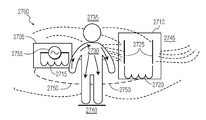
- FIG. 27 illustrates another embodiment of an EIR system.
- the EIR system includes a transmitter 2705 in communication with a receiver 2710 .
- This transmitter 2705 is similar to the transmitter XMTR in FIG. 1 , except that it uses only a coil 2715 for its antenna.
- the coil 2715 is coupled to a source 2755 similar to sources S 1 or S 2 in FIG. 1 .
- the source 2755 may drive a current through antenna coil 2715 and generating a magnetic field that is passed through the body 2735 with the same attenuation as in air because the magnetic permeability ⁇ is the same for the human body bio material as for air.
- the magnetic field is attenuated by the 3rd power of the distance, which is an attenuation of 18 db per doubling of the distance.
- the body 2735 may be positioned on a floor 2740 which may be conductive or not.
- the coil 2715 is positioned close to the human skin and may make contact or not.
- the coil 2715 generates a magnetic field 2750 .
- the magnetic field 2750 generates an electric field 2745 with a direction perpendicular to the body 2735 . This electric field is bound to the human body 2735 . As a result an electric field 2745 is available around the body 2735 .
- the receiver 2710 may receive and detect this electric field 2745 .
- the electric field may induce weak currents 2730 in the body 2735 .
- the electric field 2745 may be measured around and on the whole body 2735 and is strongest near the coil 2715 .
- the electric field 2745 is attenuated less than magnetic field 2750 along the body.
- the irregular shape of the body along a transmission path may provide additional attenuation. This is different compared with a transmission path in air where the electric field is attenuated with the 3rd power of the distance.
- Coil 2715 can be any design. Such design may be made to produce as strong of a magnetic and electric field as possible within the physical constraints of the device implementing the transmitter 2705 .
- a larger coil may produce a larger magnetic and electric field.
- a planar coil may produce a larger magnetic and electric field than a coil using a magnetic core. The increase in electric field may be due to the capacitance between the adjacent windings of the coil. Further, larger voltages across the coil will produce stronger magnetic and electric fields.
- the receiver 2710 is similar to the receiver RCVR in FIG. 1 . It receives the magnetic field 2750 and electric field 2745 generated by the coil 2715 . Thus the transmitter 2715 produces induction fields including magnetic fields 2750 and electric fields 2745 close to the body that may be received the receiver 2710 at another place at the body. As previously described, these induction fields may be received by the receiver 2710 using two antennas. The first antenna which is a coil 2720 is sensitive to the magnetic field 2750 , and the second which is a capacitor 2725 is sensitive to the electric field 2745 . The signals from both antennas may be combined in an efficient way to establish a communication link budget that is superior to a magnetic induction (MI) system. The operation of the receiver 2710 is similar to the operation of the receiver RCVR in FIG. 1 .
- MI magnetic induction
- FIG. 28 illustrates simulation results comparing the received voltage in the EIR system of FIG. 27 with a MI system.
- a ferrite coil of 9 mm long and a diameter of 2 mm was used as the transmitter antenna.
- This sort of hearing aid coil is used today in a behind the ear application. The coil is positioned 2 mm from the skin of a human.
- the electric sensitive antenna is a capacitor with rectangular plates of 20 ⁇ 20 mm and 4 mm separation.
- the magnetic sensitive antenna was a ferrite coil of 9 mm long and a diameter of 2 mm like that used as the transmitter antenna. Both electric and magnetic antennas are combined in a parallel resonance circuit and the relative received voltage as recorded as shown in FIG. 28 . Further, voltages for the MI system were recorded as well as also shown in FIG. 28 . It can be seen that the received voltage according the EIR system is always higher as compared with the art magnetic induction system.
- an EIR communication system is still possible where the one of the transmitter/receiver uses only a coil for an antenna as long as the other transmitter/receiver using both a coil and a capacitor. This still allows for communication around a body. Further, the use of EIR improves performance over a system that only use one of the fields.
- the EIR embodiments are much less sensitive to the relative orientation of both antennas than MI radio. Hence, the use of multiple coils in the external device to provide antenna diversity may be avoided while still having robust communication under all circumstances and orientations.
- efficient EMI antennas may be constructed without making use of ferrite rod-based coils but by simple planar wound coils and capacitance plates as described above. This may reduce the required antenna volume and allows for further miniaturization of the remote device. Additionally, it avoids the use of expensive ferrite rods.
- a bridge device or a remote control could be in the form of an elegant smart watch, which may be worn inconspicuously around the wrist hence protecting the privacy of the hearing aid wearer.
- Another important use case for the above described EIR system using the body antennas involves the binaural use case where audio from the one hearing aid is transmitted to the other hearing aid and vice versa. This allows the hearing aids to perform audio beam forming, resulting in increased intelligibility of sounds for the hearing aid user.
- Support of binaural communication has however been limited mostly so far to so-called behind-the-ear (BTE) devices because of size restrictions and small batteries.
- BTE behind-the-ear
- MI communication requires large ferrite rod MI antennas that cannot be used in in-the-ear (ITE) or in-the-canal (ITC) hearing aids. Further, MI transmission requires instantaneous current spikes that cannot be supplied by small batteries used in ITE and ITC devices.
- propagating objects other than a living body may be used in the described embodiments.
- the first and a second device may be connected through magnetic and electric near-field coupling using the propagating objects to help propagate the fields.
Abstract
Description
where VTx is the transmitter voltage on the transmitter antennas and VRx is the received voltage on the receiver antennas.
I m =V m /Z coil,
Z coil=2πfL coil
C=∈o×∈r×A/D,
where C is capacitance in farads, A is the surface area of one coil, D is the distance between the coils, ∈o is the permittivity of free space, 8.854×10⁻¹² F/m, and ∈r is the relative permittivity of the material between the coils.
where Vsource is the voltage across the coils, P is the dipole moment, ∈ is the permittivity of the material between the coils, and r is the distance from the coils.
P=Q×D,
where P is the dipole moment, Q is the charge on the coils, and D is the distance between the coils. Calculating the resulting charge Q on the coils can be done by the relationship:
Q=C×V source.
Claims (20)
Priority Applications (6)
| Application Number | Priority Date | Filing Date | Title |
|---|---|---|---|
| US14/576,030 US9819075B2 (en) | 2014-05-05 | 2014-12-18 | Body communication antenna |
| US14/576,583 US9819395B2 (en) | 2014-05-05 | 2014-12-19 | Apparatus and method for wireless body communication |
| EP15164622.1A EP2942877A1 (en) | 2014-05-05 | 2015-04-22 | Apparatus and method for wireless body communication |
| EP15164678.3A EP2942878B1 (en) | 2014-05-05 | 2015-04-22 | Body communication antenna |
| CN201510224026.9A CN105098380B (en) | 2014-05-05 | 2015-05-05 | Body communication antenna |
| CN201510224003.8A CN105099482B (en) | 2014-05-05 | 2015-05-05 | Body communication antenna |
Applications Claiming Priority (3)
| Application Number | Priority Date | Filing Date | Title |
|---|---|---|---|
| US14/270,013 US10015604B2 (en) | 2014-05-05 | 2014-05-05 | Electromagnetic induction field communication |
| US14/302,791 US9197986B1 (en) | 2014-06-12 | 2014-06-12 | Electromagnetic induction radio |
| US14/576,030 US9819075B2 (en) | 2014-05-05 | 2014-12-18 | Body communication antenna |
Related Parent Applications (1)
| Application Number | Title | Priority Date | Filing Date |
|---|---|---|---|
| US14/270,013 Continuation-In-Part US10015604B2 (en) | 2014-05-05 | 2014-05-05 | Electromagnetic induction field communication |
Related Child Applications (1)
| Application Number | Title | Priority Date | Filing Date |
|---|---|---|---|
| US14/302,791 Continuation US9197986B1 (en) | 2014-05-05 | 2014-06-12 | Electromagnetic induction radio |
Publications (2)
| Publication Number | Publication Date |
|---|---|
| US20150318603A1 US20150318603A1 (en) | 2015-11-05 |
| US9819075B2 true US9819075B2 (en) | 2017-11-14 |
Family
ID=52991646
Family Applications (1)
| Application Number | Title | Priority Date | Filing Date |
|---|---|---|---|
| US14/576,030 Active US9819075B2 (en) | 2014-05-05 | 2014-12-18 | Body communication antenna |
Country Status (3)
| Country | Link |
|---|---|
| US (1) | US9819075B2 (en) |
| EP (1) | EP2942878B1 (en) |
| CN (1) | CN105098380B (en) |
Cited By (9)
| Publication number | Priority date | Publication date | Assignee | Title |
|---|---|---|---|---|
| US20170338858A1 (en) * | 2014-08-29 | 2017-11-23 | Freelinc Technologies Inc. | Spatially aware communications using radio frequency (rf) communications standards |
| US10567891B1 (en) | 2018-12-07 | 2020-02-18 | Starkey Laboratories, Inc. | Ear-wearable device having tunnel with receiver coil |
| US10715189B2 (en) * | 2016-03-09 | 2020-07-14 | Kyocera Corporation | Electronic device |
| US10764667B2 (en) | 2018-12-07 | 2020-09-01 | Starkey Laboratories, Inc. | Ear-wearable device having tunnel with electrical contact pins |
| US11038556B1 (en) | 2020-06-25 | 2021-06-15 | Nxp B.V. | Near-field communications device |
| US11108436B1 (en) | 2020-05-26 | 2021-08-31 | Nxp B.V. | Near-field wireless device |
| US11108437B1 (en) | 2020-07-02 | 2021-08-31 | Nxp B.V. | Near-field communications device |
| US20220085504A1 (en) * | 2020-09-11 | 2022-03-17 | Nxp B.V. | Near-field communications device |
| US11777216B2 (en) | 2018-03-26 | 2023-10-03 | Nxp B.V. | Near-field communications device |
Families Citing this family (17)
| Publication number | Priority date | Publication date | Assignee | Title |
|---|---|---|---|---|
| US10015604B2 (en) | 2014-05-05 | 2018-07-03 | Nxp B.V. | Electromagnetic induction field communication |
| US9812788B2 (en) | 2014-11-24 | 2017-11-07 | Nxp B.V. | Electromagnetic field induction for inter-body and transverse body communication |
| US9819395B2 (en) | 2014-05-05 | 2017-11-14 | Nxp B.V. | Apparatus and method for wireless body communication |
| US10009069B2 (en) | 2014-05-05 | 2018-06-26 | Nxp B.V. | Wireless power delivery and data link |
| US10014578B2 (en) | 2014-05-05 | 2018-07-03 | Nxp B.V. | Body antenna system |
| US9661426B2 (en) | 2015-06-22 | 2017-05-23 | Gn Hearing A/S | Hearing aid having combined antennas |
| US9819097B2 (en) | 2015-08-26 | 2017-11-14 | Nxp B.V. | Antenna system |
| US10320086B2 (en) * | 2016-05-04 | 2019-06-11 | Nxp B.V. | Near-field electromagnetic induction (NFEMI) antenna |
| US10764695B2 (en) * | 2016-12-20 | 2020-09-01 | Sonova Ag | BTE hearing instrument comprising an open-end transmission line antenna |
| US10622729B2 (en) | 2018-05-25 | 2020-04-14 | Nxp B.V. | Near-field antenna |
| US10615502B2 (en) | 2018-06-29 | 2020-04-07 | Nxp B.V. | Near-field electromagnetic induction (NFEMI) antenna |
| US10992392B2 (en) * | 2018-09-06 | 2021-04-27 | Nxp B.V. | Near-field electromagnetic induction (NFEMI) ratio control |
| US10763921B1 (en) * | 2019-09-11 | 2020-09-01 | Nxp B.V. | Near-field electromagnetic induction device |
| CN112564295B (en) * | 2019-09-25 | 2023-09-08 | 华为技术有限公司 | Wireless charging system |
| US11368193B2 (en) * | 2020-02-04 | 2022-06-21 | Nxp B.V. | Near-field electromagnetic induction (NFEMI) antenna |
| US11791865B2 (en) * | 2020-02-24 | 2023-10-17 | Qualcomm Incorporated | Near electric field communication |
| US11296750B2 (en) | 2020-05-12 | 2022-04-05 | Nxp B.V. | Near-field wireless device including a first near-field antenna and a second near-field antenna |
Citations (122)
| Publication number | Priority date | Publication date | Assignee | Title |
|---|---|---|---|---|
| US3766476A (en) | 1971-05-21 | 1973-10-16 | United Communications Ind Inc | Highway radio communication system |
| US4334315A (en) | 1979-05-04 | 1982-06-08 | Gen Engineering, Ltd. | Wireless transmitting and receiving systems including ear microphones |
| US4692743A (en) * | 1984-04-06 | 1987-09-08 | Holden Harold C | Alarm system |
| US5673054A (en) | 1991-05-09 | 1997-09-30 | Seiko Epson Corporation | Antenna and miniature portable wireless transceiver |
| US5708732A (en) | 1996-03-06 | 1998-01-13 | Hewlett-Packard Company | Fast DCT domain downsampling and inverse motion compensation |
| US5907522A (en) * | 1996-05-03 | 1999-05-25 | Eta Sa Fabriques D'ebauches | Portable device for receiving and/or transmitting radio-transmitted messages comprising an inductive capacitive antenna |
| US5914701A (en) | 1995-05-08 | 1999-06-22 | Massachusetts Institute Of Technology | Non-contact system for sensing and signalling by externally induced intra-body currents |
| US5926573A (en) | 1996-01-29 | 1999-07-20 | Matsushita Electric Corporation Of America | MPEG bit-stream format converter for changing resolution |
| US5948006A (en) | 1998-10-14 | 1999-09-07 | Advanced Bionics Corporation | Transcutaneous transmission patch |
| US6104913A (en) | 1998-03-11 | 2000-08-15 | Bell Atlantic Network Services, Inc. | Personal area network for personal telephone services |
| US6211799B1 (en) | 1997-11-06 | 2001-04-03 | Massachusetts Institute Of Technology | Method and apparatus for transbody transmission of power and information |
| US6223018B1 (en) | 1996-12-12 | 2001-04-24 | Nippon Telegraph And Telephone Corporation | Intra-body information transfer device |
| US6275737B1 (en) | 1998-10-14 | 2001-08-14 | Advanced Bionics Corporation | Transcutaneous transmission pouch |
| US20020003503A1 (en) | 2000-07-06 | 2002-01-10 | Justice Christopher M. | Twin coil antenna |
| US6424820B1 (en) | 1999-04-02 | 2002-07-23 | Interval Research Corporation | Inductively coupled wireless system and method |
| US20020181579A1 (en) | 2001-05-11 | 2002-12-05 | Anthony Vetro | Video transcoder with spatial resolution reduction and drift compensation |
| WO2003030991A1 (en) | 2001-10-10 | 2003-04-17 | Massachusetts Institute Of Technology | Power saving system for neural implant devices |
| US20040023216A1 (en) | 2002-05-10 | 2004-02-05 | Board Of Trustees Of The University Of Illinois | Fluorescence based biosensor |
| US20040027296A1 (en) | 2002-08-06 | 2004-02-12 | Louis Gerber | Hand-held transmitter and/or receiver unit |
| US6754472B1 (en) | 2000-04-27 | 2004-06-22 | Microsoft Corporation | Method and apparatus for transmitting power and data using the human body |
| US20040138723A1 (en) | 2003-01-10 | 2004-07-15 | Crista Malick | Systems, devices, and methods of wireless intrabody communication |
| US6816600B1 (en) * | 2000-01-13 | 2004-11-09 | Phonak Ag | Remote control for a hearing aid, and applicable hearing aid |
| US20050058201A1 (en) | 2003-09-17 | 2005-03-17 | Fernandes Felix C. | Transcoders and methods |
| US20060008038A1 (en) | 2004-07-12 | 2006-01-12 | Microsoft Corporation | Adaptive updates in motion-compensated temporal filtering |
| US20060114993A1 (en) | 2004-07-13 | 2006-06-01 | Microsoft Corporation | Spatial scalability in 3D sub-band decoding of SDMCTF-encoded video |
| US20060134918A1 (en) | 2004-12-17 | 2006-06-22 | Semiconductor Energy Laboratory Co., Ltd. | Manufacturing method of substrate having conductive layer and manufacturing method of semiconductor device |
| US20060215919A1 (en) | 2001-12-17 | 2006-09-28 | Microsoft Corporation | Spatial extrapolation of pixel values in intraframe video coding and decoding |
| US20060233258A1 (en) | 2005-04-15 | 2006-10-19 | Microsoft Corporation | Scalable motion estimation |
| US20060252371A1 (en) | 2005-04-18 | 2006-11-09 | Sony Corporation | Human body communication system and communication device |
| US7142681B2 (en) | 2003-02-12 | 2006-11-28 | Siemens Audiologische Technik Gmbh | Device and method to remotely operate a hearing device |
| US7171177B2 (en) | 2004-09-07 | 2007-01-30 | Electronics And Telecommunications Research Institute | Communication apparatus and method using human body as medium |
| US20070058713A1 (en) | 2005-09-14 | 2007-03-15 | Microsoft Corporation | Arbitrary resolution change downsizing decoder |
| US7206423B1 (en) | 2000-05-10 | 2007-04-17 | Board Of Trustees Of University Of Illinois | Intrabody communication for a hearing aid |
| US20070116308A1 (en) | 2005-11-04 | 2007-05-24 | Motorola, Inc. | Hearing aid compatibility mode switching for a mobile station |
| US7254246B2 (en) | 2001-03-13 | 2007-08-07 | Phonak Ag | Method for establishing a binaural communication link and binaural hearing devices |
| US20070190940A1 (en) | 2006-02-10 | 2007-08-16 | Samsung Electronics Co., Ltd. | System and method for human body communication |
| US20070291970A1 (en) * | 2006-05-30 | 2007-12-20 | Siemens Audiologische Technik Gmbh | Hearing system with wideband pulse transmitter |
| US20080182517A1 (en) | 2006-12-11 | 2008-07-31 | Uwe Rass | Hearing apparatus including transponder detection and corresponding control method |
| US20080186241A1 (en) | 2007-02-01 | 2008-08-07 | Ami Semiconductor, Inc. | Body radiation and conductivity in rf communication |
| US20080261523A1 (en) | 2005-05-17 | 2008-10-23 | Fumio Kubono | Communication Device and Method, and Program |
| US20080262376A1 (en) | 2007-04-17 | 2008-10-23 | Proactive Health Devices, Inc. | Wireless sensor system for monitoring skin condition using the body as communication conduit |
| US20080267436A1 (en) | 2005-12-19 | 2008-10-30 | Nxp B.V. | Radio Receiver, Radio Transmitter, and Hearing Aid |
| US20090041241A1 (en) | 2007-08-08 | 2009-02-12 | Radeum, Inc. | Near field communications system having enhanced security |
| US20090067653A1 (en) | 2007-07-06 | 2009-03-12 | Cochlear Limited | Wireless communication between devices of a hearing prosthesis |
| US7509092B2 (en) | 2005-05-17 | 2009-03-24 | Sony Corporation | Information processing system and information processing method |
| US20090202084A1 (en) | 2008-02-13 | 2009-08-13 | Siemens Medical Instruments Pte. Ltd. | Method and Apparatus for Monitoring a Hearing Aid |
| US20090238279A1 (en) | 2008-03-21 | 2009-09-24 | Microsoft Corporation | Motion-compensated prediction of inter-layer residuals |
| US20090315787A1 (en) | 2006-07-28 | 2009-12-24 | Siemens Audiologische Technik Gmbh | Antenna arrangement for hearing device applications |
| US20090322540A1 (en) * | 2008-06-27 | 2009-12-31 | Richardson Neal T | Autonomous fall monitor |
| US20100036773A1 (en) | 2008-08-05 | 2010-02-11 | Broadcom Corporation | Integrated wireless resonant power charging and communication channel |
| US7684769B2 (en) | 2005-12-16 | 2010-03-23 | Korea Advanced Institute Of Science And Technology | Data communication apparatus and module using human body |
| US20100136905A1 (en) | 2007-04-11 | 2010-06-03 | Oticon A./S | A wireless communication device for inductive coupling to another device |
| US7783067B1 (en) | 2005-08-11 | 2010-08-24 | At&T Mobility Ii Llc | System and method for enhancing the inductive coupling between a hearing aid operating in telecoil mode and a communication device |
| US7796943B2 (en) | 2007-03-28 | 2010-09-14 | Lockheed Martin Corporation | Sub-surface communications system and method |
| US20100311326A1 (en) | 2007-12-20 | 2010-12-09 | Koninklijke Philips Electronics N.V. | Switching between multiple coupling modes |
| US20110029041A1 (en) | 2009-07-30 | 2011-02-03 | Pieter Wiskerke | Hearing prosthesis with an implantable microphone system |
| US20110046730A1 (en) | 2008-03-31 | 2011-02-24 | Werner Meskens | Implantable microphone system |
| US7907057B2 (en) * | 2006-05-04 | 2011-03-15 | Nxp B.V. | Communication device and an electric circuit for a communication device |
| CN102013895A (en) | 2010-12-13 | 2011-04-13 | 惠州市硕贝德通讯科技有限公司 | Method for solving electromagnetic compatibility problem of antenna of minitype terminal mobile phone |
| US20110137649A1 (en) | 2009-12-03 | 2011-06-09 | Rasmussen Crilles Bak | method for dynamic suppression of surrounding acoustic noise when listening to electrical inputs |
| US20110196452A1 (en) | 2008-10-10 | 2011-08-11 | Milux Holding S.A. | Method and apparatus for supplying energy to an implant |
| US8005547B2 (en) | 2003-10-02 | 2011-08-23 | Medtronic, Inc. | Inductively rechargeable external energy source, charger, system and method for a transcutaneous inductive charger for an implantable medical device |
| US20110250837A1 (en) | 2008-12-24 | 2011-10-13 | Electronics And Telecommunications Research Institute | Communications system and method using a part of human body as an antenna in a body area network |
| US20110248673A1 (en) * | 2010-04-09 | 2011-10-13 | Nxp B.V. | Apparatus for transferring energy to an accumulator and system for charging an electric accumulator |
| US20110255702A1 (en) | 2010-04-20 | 2011-10-20 | Jesper Jensen | Signal dereverberation using environment information |
| US20110300801A1 (en) * | 2010-06-03 | 2011-12-08 | Nxp B.V. | Radio receiver and transmitter circuits and methods |
| US20120032778A1 (en) | 2010-08-06 | 2012-02-09 | Sony Corporation | Communication system and communication device |
| CN102570000A (en) | 2010-10-12 | 2012-07-11 | Gn瑞声达A/S | An antenna system for a hearing aid |
| US8237622B2 (en) | 2006-12-28 | 2012-08-07 | Philtech Inc. | Base sheet |
| US8265554B2 (en) | 2006-06-20 | 2012-09-11 | Electronics And Telecommunications Research Institute | Communication device and method using human body |
| US20130002517A1 (en) | 2011-07-01 | 2013-01-03 | Mattia Pascolini | Electronic device with magnetic antenna mounting |
| US8401470B2 (en) | 2007-06-27 | 2013-03-19 | Nxp B.V. | Transmitter with adjustable transmit level for magnetic link |
| CN103024621A (en) | 2012-11-16 | 2013-04-03 | 青岛歌尔声学科技有限公司 | Bluetooth headset and method for utilizing Bluetooth headset to communicate |
| US8452234B2 (en) | 2008-06-13 | 2013-05-28 | Sanyo Semiconductor Co., Ltd. | Communication system and receiver used in communication system |
| US20130148828A1 (en) | 2011-12-09 | 2013-06-13 | Andrew Fort | Controlling a Link for Different Load Conditions |
| US20130171933A1 (en) | 2008-02-29 | 2013-07-04 | Broadcom Corporation | Integrated circuit with millimeter wave and inductive coupling and methods for use therewith |
| US8509689B2 (en) | 2009-07-22 | 2013-08-13 | Alps Electric Co., Ltd. | Communication device and communication method |
| US20130278470A1 (en) | 2012-04-18 | 2013-10-24 | Kabushiki Kaisha Toshiba | Communication apparatus |
| US20130308805A1 (en) | 2010-10-12 | 2013-11-21 | Sinasi Özden | Antenna device |
| US8606177B2 (en) | 2007-05-02 | 2013-12-10 | Samsung Electronics Co., Ltd. | Apparatus and method for controlling human body contact of ground electrode, and human body communication system using the same |
| WO2013183575A1 (en) | 2012-06-04 | 2013-12-12 | 株式会社村田製作所 | Antenna apparatus and wireless communication apparatus |
| US20130339025A1 (en) | 2011-05-03 | 2013-12-19 | Suhami Associates Ltd. | Social network with enhanced audio communications for the Hearing impaired |
| US20140008446A1 (en) | 2011-09-14 | 2014-01-09 | William N. Carr | Compact multi-band antenna |
| US20140023216A1 (en) * | 2012-07-17 | 2014-01-23 | Starkey Laboratories, Inc. | Hearing assistance device with wireless communication for on- and off- body accessories |
| US8644542B2 (en) | 2009-09-08 | 2014-02-04 | Siemens Medical Instruments Pte. Ltd. | Hearing aid with wireless battery charging capability |
| US20140049440A1 (en) | 2011-05-09 | 2014-02-20 | Murata Manufacturing Co., Ltd. | Coupling degree adjustment circuit, antenna device, and wireless communication device |
| US20140062212A1 (en) | 2008-09-12 | 2014-03-06 | University Of Pittsburgh - Of The Commonwealth System Of Higher Education | Wireless Energy Transfer System |
| US20140213184A1 (en) | 2012-08-24 | 2014-07-31 | Panasonic Healthcare Co., Ltd. | Intra-body communication apparatus provided with magnetic induction wireless communication circuit performing wireless communications using magnetic induction |
| US8797148B2 (en) | 2008-03-03 | 2014-08-05 | Murata Manufacturing Co., Ltd. | Radio frequency IC device and radio communication system |
| US20140241555A1 (en) | 2013-02-25 | 2014-08-28 | Apple Inc. | Wirelessly Charged Electronic Device With Shared Inductor Circuitry |
| US8829725B2 (en) | 2010-03-19 | 2014-09-09 | Tdk Corporation | Wireless power feeder, wireless power receiver, and wireless power transmission system |
| US20140315486A1 (en) | 2011-06-21 | 2014-10-23 | Apple Inc | Transmitter for Near-Field Chip-to-Chip Multichannel Transmission |
| US20140320369A1 (en) | 2013-04-24 | 2014-10-30 | Broadcom Corporation | Shielding layer for a device having a plurality of antennas |
| US8878735B2 (en) | 2012-06-25 | 2014-11-04 | Gn Resound A/S | Antenna system for a wearable computing device |
| US8892055B2 (en) | 2009-05-28 | 2014-11-18 | Rockwell Automation Technologies, Inc. | Wireless user interface system performance monitoring |
| US20140340032A1 (en) | 2013-05-16 | 2014-11-20 | Microchip Technology Incorporated | Wireless Door Lock Power Transfer System Having Communications Capabilities |
| US8909966B2 (en) | 2010-03-26 | 2014-12-09 | Advantest Corporation | Wireless power supply apparatus |
| US20150001956A1 (en) | 2013-06-27 | 2015-01-01 | Tdk Corporation | Wireless power receiving device, and wireless power transmission device |
| US20150028690A1 (en) * | 2012-03-16 | 2015-01-29 | Sony Corporation | Power supply device, power receiving device, power supply method, power receiving method, and program |
| US20150038864A1 (en) | 2013-08-01 | 2015-02-05 | Kabushiki Kaisha Toshiba | Living body detection sensor, communication apparatus having living body detection sensor, metal detection sensor |
| US20150038075A1 (en) | 2013-08-01 | 2015-02-05 | Kabushiki Kaisha Toshiba | Living body communication apparatus |
| US20150048985A1 (en) | 2013-08-13 | 2015-02-19 | Samsung Electro-Mechanics Co., Ltd. | Antenna module for near field communication |
| US20150061587A1 (en) | 2013-08-30 | 2015-03-05 | Airbus Operations Gmbh | Method And Device For Communication With A Personal Electronic Device In An Aircraft |
| US20150079902A1 (en) | 2012-05-07 | 2015-03-19 | St-Ericsson Sa | NFC Tag Emulation Mode with Constant Magnetic Field |
| US20150092962A1 (en) | 2011-12-01 | 2015-04-02 | At&T Intellectual Property I, L.P. | Devices and Methods for Transferring Data Through a Human Body |
| US20150097442A1 (en) | 2013-10-08 | 2015-04-09 | Nokia Corporation | Method and apparatus for wireless power transfer |
| US9019131B2 (en) | 2009-05-18 | 2015-04-28 | Samsung Electronics Co., Ltd | Terminal and method for executing function using human body communication |
| US9024725B2 (en) | 2009-11-04 | 2015-05-05 | Murata Manufacturing Co., Ltd. | Communication terminal and information processing system |
| US20150130465A1 (en) | 2012-04-19 | 2015-05-14 | New York University | Dipole array arrangement |
| US9083391B2 (en) | 2011-01-20 | 2015-07-14 | Triune Systems, LLC | Wireless power transceiver system |
| US20150318932A1 (en) | 2014-05-05 | 2015-11-05 | Nxp, B.V. | Apparatus and method for wireless body communication |
| US20150318613A1 (en) | 2014-05-05 | 2015-11-05 | Nxp, B.V. | Body antenna system |
| US20150318896A1 (en) | 2014-05-05 | 2015-11-05 | Nxp B.V. | Wireless power delivery and data link |
| US20150319545A1 (en) | 2014-05-05 | 2015-11-05 | Nxp B.V. | Electromagnetic induction field communication |
| US9197986B1 (en) | 2014-06-12 | 2015-11-24 | Nxp, B.V. | Electromagnetic induction radio |
| US20150351292A1 (en) | 2014-05-30 | 2015-12-03 | Apple Inc. | Wireless Electronic Device With Magnetic Shielding Layer |
| KR101584555B1 (en) | 2015-03-04 | 2016-01-21 | 엘지전자 주식회사 | Mobile terminal and coil antenna moduel |
| US9314381B2 (en) | 2011-08-01 | 2016-04-19 | Fred Bergman Healthcare Pty. Ltd. | Capacitive wetness sensor and method for manufacturing the same |
| US20160189860A1 (en) | 2012-12-10 | 2016-06-30 | Intel Corporation | Cascaded coils for multi-surface coverage in near field communication |
| US9455771B2 (en) | 2011-03-22 | 2016-09-27 | Freelinc Technologies Inc. | System and method for close proximity communication |
| US20170125883A1 (en) | 2014-07-02 | 2017-05-04 | Murata Manufacturing Co., Ltd. | Antenna device, antenna module, and communication terminal apparatus |
| US9647462B2 (en) | 2010-10-19 | 2017-05-09 | Sonova Ag | Hearing instrument comprising a rechargeable power source |
-
2014
- 2014-12-18 US US14/576,030 patent/US9819075B2/en active Active
-
2015
- 2015-04-22 EP EP15164678.3A patent/EP2942878B1/en active Active
- 2015-05-05 CN CN201510224026.9A patent/CN105098380B/en active Active
Patent Citations (127)
| Publication number | Priority date | Publication date | Assignee | Title |
|---|---|---|---|---|
| US3766476A (en) | 1971-05-21 | 1973-10-16 | United Communications Ind Inc | Highway radio communication system |
| US4334315A (en) | 1979-05-04 | 1982-06-08 | Gen Engineering, Ltd. | Wireless transmitting and receiving systems including ear microphones |
| US4692743A (en) * | 1984-04-06 | 1987-09-08 | Holden Harold C | Alarm system |
| US5673054A (en) | 1991-05-09 | 1997-09-30 | Seiko Epson Corporation | Antenna and miniature portable wireless transceiver |
| US5914701A (en) | 1995-05-08 | 1999-06-22 | Massachusetts Institute Of Technology | Non-contact system for sensing and signalling by externally induced intra-body currents |
| US5926573A (en) | 1996-01-29 | 1999-07-20 | Matsushita Electric Corporation Of America | MPEG bit-stream format converter for changing resolution |
| US5708732A (en) | 1996-03-06 | 1998-01-13 | Hewlett-Packard Company | Fast DCT domain downsampling and inverse motion compensation |
| US5907522A (en) * | 1996-05-03 | 1999-05-25 | Eta Sa Fabriques D'ebauches | Portable device for receiving and/or transmitting radio-transmitted messages comprising an inductive capacitive antenna |
| US6223018B1 (en) | 1996-12-12 | 2001-04-24 | Nippon Telegraph And Telephone Corporation | Intra-body information transfer device |
| US6211799B1 (en) | 1997-11-06 | 2001-04-03 | Massachusetts Institute Of Technology | Method and apparatus for transbody transmission of power and information |
| US6104913A (en) | 1998-03-11 | 2000-08-15 | Bell Atlantic Network Services, Inc. | Personal area network for personal telephone services |
| US6275737B1 (en) | 1998-10-14 | 2001-08-14 | Advanced Bionics Corporation | Transcutaneous transmission pouch |
| US5948006A (en) | 1998-10-14 | 1999-09-07 | Advanced Bionics Corporation | Transcutaneous transmission patch |
| US6424820B1 (en) | 1999-04-02 | 2002-07-23 | Interval Research Corporation | Inductively coupled wireless system and method |
| US6816600B1 (en) * | 2000-01-13 | 2004-11-09 | Phonak Ag | Remote control for a hearing aid, and applicable hearing aid |
| US6754472B1 (en) | 2000-04-27 | 2004-06-22 | Microsoft Corporation | Method and apparatus for transmitting power and data using the human body |
| US7206423B1 (en) | 2000-05-10 | 2007-04-17 | Board Of Trustees Of University Of Illinois | Intrabody communication for a hearing aid |
| US20020003503A1 (en) | 2000-07-06 | 2002-01-10 | Justice Christopher M. | Twin coil antenna |
| US7254246B2 (en) | 2001-03-13 | 2007-08-07 | Phonak Ag | Method for establishing a binaural communication link and binaural hearing devices |
| US20020181579A1 (en) | 2001-05-11 | 2002-12-05 | Anthony Vetro | Video transcoder with spatial resolution reduction and drift compensation |
| WO2003030991A1 (en) | 2001-10-10 | 2003-04-17 | Massachusetts Institute Of Technology | Power saving system for neural implant devices |
| US20060215919A1 (en) | 2001-12-17 | 2006-09-28 | Microsoft Corporation | Spatial extrapolation of pixel values in intraframe video coding and decoding |
| US20040023216A1 (en) | 2002-05-10 | 2004-02-05 | Board Of Trustees Of The University Of Illinois | Fluorescence based biosensor |
| US20040027296A1 (en) | 2002-08-06 | 2004-02-12 | Louis Gerber | Hand-held transmitter and/or receiver unit |
| US20040138723A1 (en) | 2003-01-10 | 2004-07-15 | Crista Malick | Systems, devices, and methods of wireless intrabody communication |
| US7142681B2 (en) | 2003-02-12 | 2006-11-28 | Siemens Audiologische Technik Gmbh | Device and method to remotely operate a hearing device |
| US20050058201A1 (en) | 2003-09-17 | 2005-03-17 | Fernandes Felix C. | Transcoders and methods |
| US8005547B2 (en) | 2003-10-02 | 2011-08-23 | Medtronic, Inc. | Inductively rechargeable external energy source, charger, system and method for a transcutaneous inductive charger for an implantable medical device |
| US20060008038A1 (en) | 2004-07-12 | 2006-01-12 | Microsoft Corporation | Adaptive updates in motion-compensated temporal filtering |
| US20060114993A1 (en) | 2004-07-13 | 2006-06-01 | Microsoft Corporation | Spatial scalability in 3D sub-band decoding of SDMCTF-encoded video |
| US7171177B2 (en) | 2004-09-07 | 2007-01-30 | Electronics And Telecommunications Research Institute | Communication apparatus and method using human body as medium |
| US20060134918A1 (en) | 2004-12-17 | 2006-06-22 | Semiconductor Energy Laboratory Co., Ltd. | Manufacturing method of substrate having conductive layer and manufacturing method of semiconductor device |
| US20060233258A1 (en) | 2005-04-15 | 2006-10-19 | Microsoft Corporation | Scalable motion estimation |
| US20060252371A1 (en) | 2005-04-18 | 2006-11-09 | Sony Corporation | Human body communication system and communication device |
| US7664476B2 (en) | 2005-04-18 | 2010-02-16 | Sony Corporation | Human body communication system and communication device |
| US8280302B2 (en) | 2005-05-17 | 2012-10-02 | Sony Corporation | Communication device and method, and program |
| US7509092B2 (en) | 2005-05-17 | 2009-03-24 | Sony Corporation | Information processing system and information processing method |
| US20080261523A1 (en) | 2005-05-17 | 2008-10-23 | Fumio Kubono | Communication Device and Method, and Program |
| US7783067B1 (en) | 2005-08-11 | 2010-08-24 | At&T Mobility Ii Llc | System and method for enhancing the inductive coupling between a hearing aid operating in telecoil mode and a communication device |
| US20070058713A1 (en) | 2005-09-14 | 2007-03-15 | Microsoft Corporation | Arbitrary resolution change downsizing decoder |
| US20070116308A1 (en) | 2005-11-04 | 2007-05-24 | Motorola, Inc. | Hearing aid compatibility mode switching for a mobile station |
| US7684769B2 (en) | 2005-12-16 | 2010-03-23 | Korea Advanced Institute Of Science And Technology | Data communication apparatus and module using human body |
| US20080267436A1 (en) | 2005-12-19 | 2008-10-30 | Nxp B.V. | Radio Receiver, Radio Transmitter, and Hearing Aid |
| US20070190940A1 (en) | 2006-02-10 | 2007-08-16 | Samsung Electronics Co., Ltd. | System and method for human body communication |
| US7907057B2 (en) * | 2006-05-04 | 2011-03-15 | Nxp B.V. | Communication device and an electric circuit for a communication device |
| US20070291970A1 (en) * | 2006-05-30 | 2007-12-20 | Siemens Audiologische Technik Gmbh | Hearing system with wideband pulse transmitter |
| US8265554B2 (en) | 2006-06-20 | 2012-09-11 | Electronics And Telecommunications Research Institute | Communication device and method using human body |
| US20090315787A1 (en) | 2006-07-28 | 2009-12-24 | Siemens Audiologische Technik Gmbh | Antenna arrangement for hearing device applications |
| US20080182517A1 (en) | 2006-12-11 | 2008-07-31 | Uwe Rass | Hearing apparatus including transponder detection and corresponding control method |
| US8237622B2 (en) | 2006-12-28 | 2012-08-07 | Philtech Inc. | Base sheet |
| US20080186241A1 (en) | 2007-02-01 | 2008-08-07 | Ami Semiconductor, Inc. | Body radiation and conductivity in rf communication |
| US7796943B2 (en) | 2007-03-28 | 2010-09-14 | Lockheed Martin Corporation | Sub-surface communications system and method |
| US8526879B2 (en) | 2007-04-11 | 2013-09-03 | Oticon A/S | Wireless communication device for inductive coupling to another device |
| US20100136905A1 (en) | 2007-04-11 | 2010-06-03 | Oticon A./S | A wireless communication device for inductive coupling to another device |
| US20080262376A1 (en) | 2007-04-17 | 2008-10-23 | Proactive Health Devices, Inc. | Wireless sensor system for monitoring skin condition using the body as communication conduit |
| US8606177B2 (en) | 2007-05-02 | 2013-12-10 | Samsung Electronics Co., Ltd. | Apparatus and method for controlling human body contact of ground electrode, and human body communication system using the same |
| US8401470B2 (en) | 2007-06-27 | 2013-03-19 | Nxp B.V. | Transmitter with adjustable transmit level for magnetic link |
| US20090067653A1 (en) | 2007-07-06 | 2009-03-12 | Cochlear Limited | Wireless communication between devices of a hearing prosthesis |
| US20090041241A1 (en) | 2007-08-08 | 2009-02-12 | Radeum, Inc. | Near field communications system having enhanced security |
| US20100311326A1 (en) | 2007-12-20 | 2010-12-09 | Koninklijke Philips Electronics N.V. | Switching between multiple coupling modes |
| US20090202084A1 (en) | 2008-02-13 | 2009-08-13 | Siemens Medical Instruments Pte. Ltd. | Method and Apparatus for Monitoring a Hearing Aid |
| US20130171933A1 (en) | 2008-02-29 | 2013-07-04 | Broadcom Corporation | Integrated circuit with millimeter wave and inductive coupling and methods for use therewith |
| US8797148B2 (en) | 2008-03-03 | 2014-08-05 | Murata Manufacturing Co., Ltd. | Radio frequency IC device and radio communication system |
| US20090238279A1 (en) | 2008-03-21 | 2009-09-24 | Microsoft Corporation | Motion-compensated prediction of inter-layer residuals |
| US20110046730A1 (en) | 2008-03-31 | 2011-02-24 | Werner Meskens | Implantable microphone system |
| US8452234B2 (en) | 2008-06-13 | 2013-05-28 | Sanyo Semiconductor Co., Ltd. | Communication system and receiver used in communication system |
| US20090322540A1 (en) * | 2008-06-27 | 2009-12-31 | Richardson Neal T | Autonomous fall monitor |
| US20100036773A1 (en) | 2008-08-05 | 2010-02-11 | Broadcom Corporation | Integrated wireless resonant power charging and communication channel |
| US20140062212A1 (en) | 2008-09-12 | 2014-03-06 | University Of Pittsburgh - Of The Commonwealth System Of Higher Education | Wireless Energy Transfer System |
| US20110196452A1 (en) | 2008-10-10 | 2011-08-11 | Milux Holding S.A. | Method and apparatus for supplying energy to an implant |
| US20110250837A1 (en) | 2008-12-24 | 2011-10-13 | Electronics And Telecommunications Research Institute | Communications system and method using a part of human body as an antenna in a body area network |
| US9019131B2 (en) | 2009-05-18 | 2015-04-28 | Samsung Electronics Co., Ltd | Terminal and method for executing function using human body communication |
| US8892055B2 (en) | 2009-05-28 | 2014-11-18 | Rockwell Automation Technologies, Inc. | Wireless user interface system performance monitoring |
| US8509689B2 (en) | 2009-07-22 | 2013-08-13 | Alps Electric Co., Ltd. | Communication device and communication method |
| US20110029041A1 (en) | 2009-07-30 | 2011-02-03 | Pieter Wiskerke | Hearing prosthesis with an implantable microphone system |
| US8644542B2 (en) | 2009-09-08 | 2014-02-04 | Siemens Medical Instruments Pte. Ltd. | Hearing aid with wireless battery charging capability |
| US9024725B2 (en) | 2009-11-04 | 2015-05-05 | Murata Manufacturing Co., Ltd. | Communication terminal and information processing system |
| US20110137649A1 (en) | 2009-12-03 | 2011-06-09 | Rasmussen Crilles Bak | method for dynamic suppression of surrounding acoustic noise when listening to electrical inputs |
| US8829725B2 (en) | 2010-03-19 | 2014-09-09 | Tdk Corporation | Wireless power feeder, wireless power receiver, and wireless power transmission system |
| US8909966B2 (en) | 2010-03-26 | 2014-12-09 | Advantest Corporation | Wireless power supply apparatus |
| US20110248673A1 (en) * | 2010-04-09 | 2011-10-13 | Nxp B.V. | Apparatus for transferring energy to an accumulator and system for charging an electric accumulator |
| US20110255702A1 (en) | 2010-04-20 | 2011-10-20 | Jesper Jensen | Signal dereverberation using environment information |
| US20110300801A1 (en) * | 2010-06-03 | 2011-12-08 | Nxp B.V. | Radio receiver and transmitter circuits and methods |
| US20120032778A1 (en) | 2010-08-06 | 2012-02-09 | Sony Corporation | Communication system and communication device |
| US20130308805A1 (en) | 2010-10-12 | 2013-11-21 | Sinasi Özden | Antenna device |
| CN102570000A (en) | 2010-10-12 | 2012-07-11 | Gn瑞声达A/S | An antenna system for a hearing aid |
| US9647462B2 (en) | 2010-10-19 | 2017-05-09 | Sonova Ag | Hearing instrument comprising a rechargeable power source |
| CN102013895A (en) | 2010-12-13 | 2011-04-13 | 惠州市硕贝德通讯科技有限公司 | Method for solving electromagnetic compatibility problem of antenna of minitype terminal mobile phone |
| US9083391B2 (en) | 2011-01-20 | 2015-07-14 | Triune Systems, LLC | Wireless power transceiver system |
| US9455771B2 (en) | 2011-03-22 | 2016-09-27 | Freelinc Technologies Inc. | System and method for close proximity communication |
| US20130339025A1 (en) | 2011-05-03 | 2013-12-19 | Suhami Associates Ltd. | Social network with enhanced audio communications for the Hearing impaired |
| US20140049440A1 (en) | 2011-05-09 | 2014-02-20 | Murata Manufacturing Co., Ltd. | Coupling degree adjustment circuit, antenna device, and wireless communication device |
| US20140315486A1 (en) | 2011-06-21 | 2014-10-23 | Apple Inc | Transmitter for Near-Field Chip-to-Chip Multichannel Transmission |
| US20130002517A1 (en) | 2011-07-01 | 2013-01-03 | Mattia Pascolini | Electronic device with magnetic antenna mounting |
| US9314381B2 (en) | 2011-08-01 | 2016-04-19 | Fred Bergman Healthcare Pty. Ltd. | Capacitive wetness sensor and method for manufacturing the same |
| US20140008446A1 (en) | 2011-09-14 | 2014-01-09 | William N. Carr | Compact multi-band antenna |
| US20150092962A1 (en) | 2011-12-01 | 2015-04-02 | At&T Intellectual Property I, L.P. | Devices and Methods for Transferring Data Through a Human Body |
| US20130148828A1 (en) | 2011-12-09 | 2013-06-13 | Andrew Fort | Controlling a Link for Different Load Conditions |
| US20150028690A1 (en) * | 2012-03-16 | 2015-01-29 | Sony Corporation | Power supply device, power receiving device, power supply method, power receiving method, and program |
| US9130273B2 (en) | 2012-04-18 | 2015-09-08 | Kabushiki Kaisha Toshiba | Communication apparatus |
| US20130278470A1 (en) | 2012-04-18 | 2013-10-24 | Kabushiki Kaisha Toshiba | Communication apparatus |
| US20150130465A1 (en) | 2012-04-19 | 2015-05-14 | New York University | Dipole array arrangement |
| US20150079902A1 (en) | 2012-05-07 | 2015-03-19 | St-Ericsson Sa | NFC Tag Emulation Mode with Constant Magnetic Field |
| WO2013183575A1 (en) | 2012-06-04 | 2013-12-12 | 株式会社村田製作所 | Antenna apparatus and wireless communication apparatus |
| US20140184462A1 (en) | 2012-06-04 | 2014-07-03 | Murata Manufacturing Co., Ltd. | Antenna module and radio communication device |
| US8878735B2 (en) | 2012-06-25 | 2014-11-04 | Gn Resound A/S | Antenna system for a wearable computing device |
| US20140023216A1 (en) * | 2012-07-17 | 2014-01-23 | Starkey Laboratories, Inc. | Hearing assistance device with wireless communication for on- and off- body accessories |
| US20140213184A1 (en) | 2012-08-24 | 2014-07-31 | Panasonic Healthcare Co., Ltd. | Intra-body communication apparatus provided with magnetic induction wireless communication circuit performing wireless communications using magnetic induction |
| CN103024621A (en) | 2012-11-16 | 2013-04-03 | 青岛歌尔声学科技有限公司 | Bluetooth headset and method for utilizing Bluetooth headset to communicate |
| US20160189860A1 (en) | 2012-12-10 | 2016-06-30 | Intel Corporation | Cascaded coils for multi-surface coverage in near field communication |
| US20140241555A1 (en) | 2013-02-25 | 2014-08-28 | Apple Inc. | Wirelessly Charged Electronic Device With Shared Inductor Circuitry |
| US20140320369A1 (en) | 2013-04-24 | 2014-10-30 | Broadcom Corporation | Shielding layer for a device having a plurality of antennas |
| US20140340032A1 (en) | 2013-05-16 | 2014-11-20 | Microchip Technology Incorporated | Wireless Door Lock Power Transfer System Having Communications Capabilities |
| US20150001956A1 (en) | 2013-06-27 | 2015-01-01 | Tdk Corporation | Wireless power receiving device, and wireless power transmission device |
| US20150038864A1 (en) | 2013-08-01 | 2015-02-05 | Kabushiki Kaisha Toshiba | Living body detection sensor, communication apparatus having living body detection sensor, metal detection sensor |
| US20150038075A1 (en) | 2013-08-01 | 2015-02-05 | Kabushiki Kaisha Toshiba | Living body communication apparatus |
| US20150048985A1 (en) | 2013-08-13 | 2015-02-19 | Samsung Electro-Mechanics Co., Ltd. | Antenna module for near field communication |
| US20150061587A1 (en) | 2013-08-30 | 2015-03-05 | Airbus Operations Gmbh | Method And Device For Communication With A Personal Electronic Device In An Aircraft |
| US20150097442A1 (en) | 2013-10-08 | 2015-04-09 | Nokia Corporation | Method and apparatus for wireless power transfer |
| US20150318932A1 (en) | 2014-05-05 | 2015-11-05 | Nxp, B.V. | Apparatus and method for wireless body communication |
| US20150318613A1 (en) | 2014-05-05 | 2015-11-05 | Nxp, B.V. | Body antenna system |
| US20150318896A1 (en) | 2014-05-05 | 2015-11-05 | Nxp B.V. | Wireless power delivery and data link |
| US20150319545A1 (en) | 2014-05-05 | 2015-11-05 | Nxp B.V. | Electromagnetic induction field communication |
| US20150351292A1 (en) | 2014-05-30 | 2015-12-03 | Apple Inc. | Wireless Electronic Device With Magnetic Shielding Layer |
| US9197986B1 (en) | 2014-06-12 | 2015-11-24 | Nxp, B.V. | Electromagnetic induction radio |
| US20170125883A1 (en) | 2014-07-02 | 2017-05-04 | Murata Manufacturing Co., Ltd. | Antenna device, antenna module, and communication terminal apparatus |
| KR101584555B1 (en) | 2015-03-04 | 2016-01-21 | 엘지전자 주식회사 | Mobile terminal and coil antenna moduel |
Non-Patent Citations (40)
| Title |
|---|
| Chandrasekar, K., "Inductively Coupled Connectors and Sockets for Multi-Gb/s Pulse Signaling," IEEE Transactions on Advanced Packaging, vol. 31, No. 4; Nov. 1, 2008, pp. 749-758. |
| Cho, et al., A Planar MICS Band Antenna Combined with a Body Channel Communication Electrode for Body Sensor Network, IEEE Transactions on Microwave Theory and Techniques, IEEE Service Center, Piscataway, NJ, US, vol. 57, No. 10, pp. 2512-2522, Oct. 1, 2009. |
| EP COMM and EP Search Report for 15164678 dated Aug. 31, 2015. |
| European Search Report dated Aug. 31, 2015 for EP 15164610, 6 pages. |
| European Search Report dated Aug. 31, 2015 for EP 15164621, 8 pages. |
| European Search Report dated Aug. 31, 2015 for EP 15164622, 6 pages. |
| Final Office Action dated Aug. 27, 2015 for U.S. Appl. No. 14/270,013, 17 pages. |
| Final Office Action dated Aug. 9, 2017 for U.S. Appl. No. 14/569,024, 52 pages. |
| Final Office Action dated Feb. 25, 2016 for U.S. Appl. No. 14/569,024, 13 pages. |
| Final Office Action dated Feb. 25, 2016 for U.S. Appl. No. 14/576,583, 13 pages. |
| Final Office Action dated Jul. 27, 2017 for U.S. Appl. No. 14/575,865, 56 pages. |
| Final Office Action dated Mar. 14, 2017 for U.S. Appl. No. 14/270,013, 37 pages. |
| Final Office Action mailed Mar. 4, 2016 for U.S. Appl. No. 14/575,865, 14 pages. |
| International Search Report and Written Opinion dated Jul. 13, 2015 for PCT/EP2015/058044, 11 pages. |
| International Search Report and Written Opinion dated Jul. 17, 2015 for PCT/EP2015/058052, 9 pages. |
| International Search Report and Written Opinion dated Jul. 7, 2015 for PCT/EP2015/058071, 11 pages. |
| Kado, et al., "RedTacton Near-body Electric-field Communications Technology and Its Applications", NTT Technical Review, vol. 8, No. 3; NTT Microsystems Integration Laboratories, Atsugi-shi, JP;, Mar. 2010, pp. 1-6. |
| Non Final Office Action dated Aug. 26, 2016 for U.S. Appl. No. 14/270,013, 13 pages. |
| Non Final Office Action dated Jun. 29, 2016 for U.S. Appl. No. 14/551,988, 23 pages. |
| Non-Final Office Action dated Feb. 29, 2016 for U.S. Appl. No. 14/270,013, 11 pages. |
| Non-Final Office Action dated Jan. 19, 2017 for U.S. Appl. No. 14/551,988, 21 pages. |
| Non-Final Office Action dated Jan. 19, 2017 for U.S. Appl. No. 14/575,865, 45 pages. |
| Non-Final Office Action dated Jan. 25, 2017 for U.S. Appl. No. 14/569,024, 51 pages. |
| Non-Final Office Action dated May 7, 2015 for U.S. Appl. No. 14/270,013, 12 pages. |
| Non-Final Office Action dated Oct. 5, 2015 for U.S. Appl. No. 14/569,024, 14 pages. |
| Non-Final Office Action dated Sep. 21, 2015 for U.S. Appl. No. 14/576,583, 17 pages. |
| Non-Final Office Action for U.S. Appl. No. 14/576,583, dated Nov. 3, 2016, 33 pages. |
| Non-Final Office Action mailed Oct. 5, 2015 for U.S. Appl. No. 14/575,865, 17 pages. |
| Notice of Allowance dated Jul. 21, 2015 for U.S. Appl. No. 14/302,791, 9 pages. |
| Notice of Allowance dated Jun. 14, 2017 for U.S. Appl. No. 14/836,681, 14 pages. |
| Notice of Allowance dated Jun. 21, 2017 for U.S. Appl. No. 14/576,583, 34 pages. |
| Notice of Allowance dated Jun. 7, 2017 for U.S. Appl. No. 14/551,988, 25 pages. |
| Ohishi, et al., Novel Pair Electrode With Coils Sensing Magnetic Energy on Human Body Surface for Intrabody Communication, Antennas and Propagation (ISAP) 2012 Int'l. Symposium on, IEEE, Oct. 29, 2012, pp. 203-206. |
| Shinagawa, M. et al., "A Near-Field-Sensing Transceiver for Intra-Body Communication Based on the Electro-Optic Effect," Instrumentation and Measurement Technology Conference, Vail, CO; May 20-22, 2003; 6 pages. |
| Tounsi, et al., Electromagnetic modeling of an integrated micromachined inductive microphone, Design & Technology of Integrated Systems in Nanoscal Era, 2009, DTIS '09, 4th Int'l Conf on, IEEE Apr. 6, 2009. |
| U.S. Appl. No. 14/551,988, filed Nov. 24, 2014, entitled "Electromagnetic Field Induction for Inter-Body and Transverse Body Communication". |
| U.S. Appl. No. 14/836,681, filed Aug. 26, 2015, entitled "Antenna System". |
| U.S. Appl. No. 15/146,665, filed May 4, 2016, entitled "Near-Field Electromagnetic Induction (NFEMI) Antenna". |
| Zimmerman, Personal Arear Networks: Near-Field Intrabody Communication, IBM Systems Journal, vol. 35, 1996, pp. 609-617. * |
| Zimmerman, T.G., "Personal Area Networks (PAN): Near-Field Intra-Body Communication," Massachusetts Institute of Technology, Jun. 1995, 81 pages. |
Cited By (13)
| Publication number | Priority date | Publication date | Assignee | Title |
|---|---|---|---|---|
| US20170338858A1 (en) * | 2014-08-29 | 2017-11-23 | Freelinc Technologies Inc. | Spatially aware communications using radio frequency (rf) communications standards |
| US10038475B2 (en) | 2014-08-29 | 2018-07-31 | Freelinc Technologies Inc. | Proximity boundary based communication using radio frequency (RF) communication standards |
| US10084512B2 (en) | 2014-08-29 | 2018-09-25 | Freelinc Technologies | Proximity boundary based communication |
| US10122414B2 (en) | 2014-08-29 | 2018-11-06 | Freelinc Technologies Inc. | Spatially enabled secure communications |
| US10715189B2 (en) * | 2016-03-09 | 2020-07-14 | Kyocera Corporation | Electronic device |
| US11777216B2 (en) | 2018-03-26 | 2023-10-03 | Nxp B.V. | Near-field communications device |
| US10764667B2 (en) | 2018-12-07 | 2020-09-01 | Starkey Laboratories, Inc. | Ear-wearable device having tunnel with electrical contact pins |
| US10567891B1 (en) | 2018-12-07 | 2020-02-18 | Starkey Laboratories, Inc. | Ear-wearable device having tunnel with receiver coil |
| US11108436B1 (en) | 2020-05-26 | 2021-08-31 | Nxp B.V. | Near-field wireless device |
| US11038556B1 (en) | 2020-06-25 | 2021-06-15 | Nxp B.V. | Near-field communications device |
| US11108437B1 (en) | 2020-07-02 | 2021-08-31 | Nxp B.V. | Near-field communications device |
| US20220085504A1 (en) * | 2020-09-11 | 2022-03-17 | Nxp B.V. | Near-field communications device |
| US11677151B2 (en) * | 2020-09-11 | 2023-06-13 | Nxp B.V. | Near-field communications device |
Also Published As
| Publication number | Publication date |
|---|---|
| CN105098380B (en) | 2019-02-15 |
| EP2942878A1 (en) | 2015-11-11 |
| CN105098380A (en) | 2015-11-25 |
| US20150318603A1 (en) | 2015-11-05 |
| EP2942878B1 (en) | 2019-12-04 |
Similar Documents
| Publication | Publication Date | Title |
|---|---|---|
| US9819075B2 (en) | Body communication antenna | |
| US9819395B2 (en) | Apparatus and method for wireless body communication | |
| US10014578B2 (en) | Body antenna system | |
| CN106486778B (en) | Antenna system | |
| US9197986B1 (en) | Electromagnetic induction radio | |
| US9432779B2 (en) | Hearing aid antenna | |
| US10347973B2 (en) | Near-field electromagnetic induction (NFEMI) antenna | |
| US9812788B2 (en) | Electromagnetic field induction for inter-body and transverse body communication | |
| CN110880640B (en) | System and method for near field electromagnetic induction (NFEMI) antennas | |
| CN106464305A (en) | Electromagnetic induction field communication | |
| EP3863186A1 (en) | Near-field electromagnetic induction (nfemi) antenna | |
| US11108437B1 (en) | Near-field communications device | |
| EP3866345B1 (en) | Near-field electromagnetic induction (nfemi) antenna | |
| EP3139816B1 (en) | Electromagnetic field induction for inter-body and transverse body communication | |
| CN106256090B (en) | Electromagnetic induction wireless communication system, method and storage medium |
Legal Events
| Date | Code | Title | Description |
|---|---|---|---|
| AS | Assignment |
Owner name: NXP, B.V., NETHERLANDS Free format text: ASSIGNMENT OF ASSIGNORS INTEREST;ASSIGNORS:KERSELAERS, ANTHONY;GOMME, LIESBETH;THOEN, STEVEN;REEL/FRAME:034552/0350 Effective date: 20141209 |
|
| AS | Assignment |
Owner name: MORGAN STANLEY SENIOR FUNDING, INC., MARYLAND Free format text: SECURITY AGREEMENT SUPPLEMENT;ASSIGNOR:NXP B.V.;REEL/FRAME:038017/0058 Effective date: 20160218 |
|
| AS | Assignment |
Owner name: MORGAN STANLEY SENIOR FUNDING, INC., MARYLAND Free format text: CORRECTIVE ASSIGNMENT TO CORRECT THE REMOVE APPLICATION 12092129 PREVIOUSLY RECORDED ON REEL 038017 FRAME 0058. ASSIGNOR(S) HEREBY CONFIRMS THE SECURITY AGREEMENT SUPPLEMENT;ASSIGNOR:NXP B.V.;REEL/FRAME:039361/0212 Effective date: 20160218 |
|
| AS | Assignment |
Owner name: MORGAN STANLEY SENIOR FUNDING, INC., MARYLAND Free format text: CORRECTIVE ASSIGNMENT TO CORRECT THE REMOVE APPLICATION 12681366 PREVIOUSLY RECORDED ON REEL 039361 FRAME 0212. ASSIGNOR(S) HEREBY CONFIRMS THE SECURITY AGREEMENT SUPPLEMENT;ASSIGNOR:NXP B.V.;REEL/FRAME:042762/0145 Effective date: 20160218 Owner name: MORGAN STANLEY SENIOR FUNDING, INC., MARYLAND Free format text: CORRECTIVE ASSIGNMENT TO CORRECT THE REMOVE APPLICATION 12681366 PREVIOUSLY RECORDED ON REEL 038017 FRAME 0058. ASSIGNOR(S) HEREBY CONFIRMS THE SECURITY AGREEMENT SUPPLEMENT;ASSIGNOR:NXP B.V.;REEL/FRAME:042985/0001 Effective date: 20160218 |
|
| STCF | Information on status: patent grant |
Free format text: PATENTED CASE |
|
| AS | Assignment |
Owner name: NXP B.V., NETHERLANDS Free format text: RELEASE BY SECURED PARTY;ASSIGNOR:MORGAN STANLEY SENIOR FUNDING, INC.;REEL/FRAME:050745/0001 Effective date: 20190903 |
|
| AS | Assignment |
Owner name: MORGAN STANLEY SENIOR FUNDING, INC., MARYLAND Free format text: CORRECTIVE ASSIGNMENT TO CORRECT THE REMOVE APPLICATION 12298143 PREVIOUSLY RECORDED ON REEL 039361 FRAME 0212. ASSIGNOR(S) HEREBY CONFIRMS THE SECURITY AGREEMENT SUPPLEMENT;ASSIGNOR:NXP B.V.;REEL/FRAME:051029/0387 Effective date: 20160218 Owner name: MORGAN STANLEY SENIOR FUNDING, INC., MARYLAND Free format text: CORRECTIVE ASSIGNMENT TO CORRECT THE REMOVE APPLICATION 12298143 PREVIOUSLY RECORDED ON REEL 042985 FRAME 0001. ASSIGNOR(S) HEREBY CONFIRMS THE SECURITY AGREEMENT SUPPLEMENT;ASSIGNOR:NXP B.V.;REEL/FRAME:051029/0001 Effective date: 20160218 Owner name: MORGAN STANLEY SENIOR FUNDING, INC., MARYLAND Free format text: CORRECTIVE ASSIGNMENT TO CORRECT THE REMOVE APPLICATION 12298143 PREVIOUSLY RECORDED ON REEL 042762 FRAME 0145. ASSIGNOR(S) HEREBY CONFIRMS THE SECURITY AGREEMENT SUPPLEMENT;ASSIGNOR:NXP B.V.;REEL/FRAME:051145/0184 Effective date: 20160218 Owner name: MORGAN STANLEY SENIOR FUNDING, INC., MARYLAND Free format text: CORRECTIVE ASSIGNMENT TO CORRECT THE REMOVE APPLICATION12298143 PREVIOUSLY RECORDED ON REEL 042985 FRAME 0001. ASSIGNOR(S) HEREBY CONFIRMS THE SECURITY AGREEMENT SUPPLEMENT;ASSIGNOR:NXP B.V.;REEL/FRAME:051029/0001 Effective date: 20160218 Owner name: MORGAN STANLEY SENIOR FUNDING, INC., MARYLAND Free format text: CORRECTIVE ASSIGNMENT TO CORRECT THE REMOVE APPLICATION 12298143 PREVIOUSLY RECORDED ON REEL 038017 FRAME 0058. ASSIGNOR(S) HEREBY CONFIRMS THE SECURITY AGREEMENT SUPPLEMENT;ASSIGNOR:NXP B.V.;REEL/FRAME:051030/0001 Effective date: 20160218 Owner name: MORGAN STANLEY SENIOR FUNDING, INC., MARYLAND Free format text: CORRECTIVE ASSIGNMENT TO CORRECT THE REMOVE APPLICATION12298143 PREVIOUSLY RECORDED ON REEL 039361 FRAME 0212. ASSIGNOR(S) HEREBY CONFIRMS THE SECURITY AGREEMENT SUPPLEMENT;ASSIGNOR:NXP B.V.;REEL/FRAME:051029/0387 Effective date: 20160218 Owner name: MORGAN STANLEY SENIOR FUNDING, INC., MARYLAND Free format text: CORRECTIVE ASSIGNMENT TO CORRECT THE REMOVE APPLICATION12298143 PREVIOUSLY RECORDED ON REEL 042762 FRAME 0145. ASSIGNOR(S) HEREBY CONFIRMS THE SECURITY AGREEMENT SUPPLEMENT;ASSIGNOR:NXP B.V.;REEL/FRAME:051145/0184 Effective date: 20160218 |
|
| MAFP | Maintenance fee payment |
Free format text: PAYMENT OF MAINTENANCE FEE, 4TH YEAR, LARGE ENTITY (ORIGINAL EVENT CODE: M1551); ENTITY STATUS OF PATENT OWNER: LARGE ENTITY Year of fee payment: 4 |