US9820017B2 - Subsea connector with data collection and communication system and method - Google Patents
Subsea connector with data collection and communication system and method Download PDFInfo
- Publication number
- US9820017B2 US9820017B2 US14/453,504 US201414453504A US9820017B2 US 9820017 B2 US9820017 B2 US 9820017B2 US 201414453504 A US201414453504 A US 201414453504A US 9820017 B2 US9820017 B2 US 9820017B2
- Authority
- US
- United States
- Prior art keywords
- subsea
- connector
- data
- data collection
- cable
- Prior art date
- Legal status (The legal status is an assumption and is not a legal conclusion. Google has not performed a legal analysis and makes no representation as to the accuracy of the status listed.)
- Active, expires
Links
- 230000006854 communication Effects 0.000 title claims abstract description 110
- 238000004891 communication Methods 0.000 title claims abstract description 110
- 238000013480 data collection Methods 0.000 title claims abstract description 61
- 238000000034 method Methods 0.000 title description 3
- 230000003287 optical effect Effects 0.000 claims abstract description 61
- 238000012544 monitoring process Methods 0.000 claims abstract description 39
- 230000007613 environmental effect Effects 0.000 claims abstract description 28
- 239000013307 optical fiber Substances 0.000 claims abstract description 16
- 238000013500 data storage Methods 0.000 claims description 8
- 230000013011 mating Effects 0.000 claims description 6
- 239000004020 conductor Substances 0.000 claims description 5
- 238000012806 monitoring device Methods 0.000 claims 3
- 239000000835 fiber Substances 0.000 abstract description 17
- 230000015556 catabolic process Effects 0.000 abstract description 6
- 238000006731 degradation reaction Methods 0.000 abstract description 6
- 238000012545 processing Methods 0.000 abstract description 5
- 230000000737 periodic effect Effects 0.000 abstract description 3
- 239000013535 sea water Substances 0.000 abstract description 2
- 230000006870 function Effects 0.000 description 11
- 238000010586 diagram Methods 0.000 description 7
- UQMRAFJOBWOFNS-UHFFFAOYSA-N butyl 2-(2,4-dichlorophenoxy)acetate Chemical group CCCCOC(=O)COC1=CC=C(Cl)C=C1Cl UQMRAFJOBWOFNS-UHFFFAOYSA-N 0.000 description 4
- 238000012423 maintenance Methods 0.000 description 4
- 230000007175 bidirectional communication Effects 0.000 description 3
- XLYOFNOQVPJJNP-UHFFFAOYSA-N water Substances O XLYOFNOQVPJJNP-UHFFFAOYSA-N 0.000 description 3
- 241001481166 Nautilus Species 0.000 description 2
- 238000010276 construction Methods 0.000 description 2
- 230000008878 coupling Effects 0.000 description 2
- 238000010168 coupling process Methods 0.000 description 2
- 238000005859 coupling reaction Methods 0.000 description 2
- 230000001939 inductive effect Effects 0.000 description 2
- 230000009286 beneficial effect Effects 0.000 description 1
- 238000006243 chemical reaction Methods 0.000 description 1
- 238000001514 detection method Methods 0.000 description 1
- 230000000694 effects Effects 0.000 description 1
- 238000009429 electrical wiring Methods 0.000 description 1
- 238000009434 installation Methods 0.000 description 1
- 239000010410 layer Substances 0.000 description 1
- 239000000463 material Substances 0.000 description 1
- 238000012986 modification Methods 0.000 description 1
- 230000004048 modification Effects 0.000 description 1
- 230000008569 process Effects 0.000 description 1
- 230000008439 repair process Effects 0.000 description 1
- 239000002356 single layer Substances 0.000 description 1
Images


Classifications
-
- H—ELECTRICITY
- H04—ELECTRIC COMMUNICATION TECHNIQUE
- H04Q—SELECTING
- H04Q9/00—Arrangements in telecontrol or telemetry systems for selectively calling a substation from a main station, in which substation desired apparatus is selected for applying a control signal thereto or for obtaining measured values therefrom
-
- E—FIXED CONSTRUCTIONS
- E21—EARTH DRILLING; MINING
- E21B—EARTH DRILLING, e.g. DEEP DRILLING; OBTAINING OIL, GAS, WATER, SOLUBLE OR MELTABLE MATERIALS OR A SLURRY OF MINERALS FROM WELLS
- E21B33/00—Sealing or packing boreholes or wells
- E21B33/02—Surface sealing or packing
- E21B33/03—Well heads; Setting-up thereof
- E21B33/035—Well heads; Setting-up thereof specially adapted for underwater installations
- E21B33/038—Connectors used on well heads, e.g. for connecting blow-out preventer and riser
-
- G—PHYSICS
- G02—OPTICS
- G02B—OPTICAL ELEMENTS, SYSTEMS OR APPARATUS
- G02B6/00—Light guides; Structural details of arrangements comprising light guides and other optical elements, e.g. couplings
- G02B6/24—Coupling light guides
- G02B6/36—Mechanical coupling means
- G02B6/38—Mechanical coupling means having fibre to fibre mating means
- G02B6/3807—Dismountable connectors, i.e. comprising plugs
- G02B6/381—Dismountable connectors, i.e. comprising plugs of the ferrule type, e.g. fibre ends embedded in ferrules, connecting a pair of fibres
- G02B6/3816—Dismountable connectors, i.e. comprising plugs of the ferrule type, e.g. fibre ends embedded in ferrules, connecting a pair of fibres for use under water, high pressure connectors
-
- G—PHYSICS
- G02—OPTICS
- G02B—OPTICAL ELEMENTS, SYSTEMS OR APPARATUS
- G02B6/00—Light guides; Structural details of arrangements comprising light guides and other optical elements, e.g. couplings
- G02B6/24—Coupling light guides
- G02B6/36—Mechanical coupling means
- G02B6/38—Mechanical coupling means having fibre to fibre mating means
- G02B6/3807—Dismountable connectors, i.e. comprising plugs
- G02B6/381—Dismountable connectors, i.e. comprising plugs of the ferrule type, e.g. fibre ends embedded in ferrules, connecting a pair of fibres
- G02B6/3817—Dismountable connectors, i.e. comprising plugs of the ferrule type, e.g. fibre ends embedded in ferrules, connecting a pair of fibres containing optical and electrical conductors
-
- G—PHYSICS
- G02—OPTICS
- G02B—OPTICAL ELEMENTS, SYSTEMS OR APPARATUS
- G02B6/00—Light guides; Structural details of arrangements comprising light guides and other optical elements, e.g. couplings
- G02B6/24—Coupling light guides
- G02B6/42—Coupling light guides with opto-electronic elements
- G02B6/4292—Coupling light guides with opto-electronic elements the light guide being disconnectable from the opto-electronic element, e.g. mutually self aligning arrangements
-
- G—PHYSICS
- G02—OPTICS
- G02B—OPTICAL ELEMENTS, SYSTEMS OR APPARATUS
- G02B6/00—Light guides; Structural details of arrangements comprising light guides and other optical elements, e.g. couplings
- G02B6/44—Mechanical structures for providing tensile strength and external protection for fibres, e.g. optical transmission cables
- G02B6/4439—Auxiliary devices
- G02B6/444—Systems or boxes with surplus lengths
- G02B6/4441—Boxes
- G02B6/4448—Electro-optic
-
- G—PHYSICS
- G02—OPTICS
- G02B—OPTICAL ELEMENTS, SYSTEMS OR APPARATUS
- G02B6/00—Light guides; Structural details of arrangements comprising light guides and other optical elements, e.g. couplings
- G02B6/46—Processes or apparatus adapted for installing or repairing optical fibres or optical cables
- G02B6/50—Underground or underwater installation; Installation through tubing, conduits or ducts
- G02B6/508—Fixation devices in ducts for drawing cables
Definitions
- the present invention relates generally to connection of equipment used in subsea operations, such as equipment used in the subsea oil and gas industry as well as telecommunications, to shore-based stations or other remote systems, and is particularly concerned with a subsea electrical, optical, or electro-optical connector unit with a built-in data collection and communication system.
- connectors for making electrical and fiber-optic cable connections in hostile or harsh environments, such as underwater or subsea electrical, optical and hybrid electrical and optical connectors which can be repeatedly mated and demated underwater at great ocean depths.
- the connectors may be electrical only, optical only, or may be hybrid electrical and optical connectors.
- These connectors typically consist of releasably mateable plug and receptacle units or connector parts, each attached to cables or other devices intended to be joined by the connectors to form completed circuits.
- Each connector unit contains one or more electrical and/or optical contacts or junctions for engagement with the junctions in the other unit when the two units are mated together.
- one or both parts of these connectors house the contacts in oil-filled, pressure-balanced chambers.
- An electrical underwater pin and socket connector is described in U.S. Pat. No. 5,645,442 of Cairns and is sold by Teledyne ODI, Inc. of Daytona Beach, Fla. under the name Nautilus®.
- Land-based systems exist that can be used to connect a data or power port to verify or measure the presence of data or power at the port, but this data is monitored locally. There is no effective way to monitor subsea installations on an ongoing basis for early detection of potential faults or potential equipment failures.
- Embodiments described herein provide a subsea data collection and communication system installed at a subsea interconnect point or connector unit used for communication between subsea electrical, optical or hybrid electro-optical cables or between a subsea cable and subsea equipment.
- the data collection and communication system may be built into the subsea connector and is configured to collect system performance data such as voltage, current, optical pressure and the like from the wires or fibers in cables connected to the connector unit, and may also collect data on environmental conditions from sensors installed in or on the connector unit, such as temperature, pressure, sea water salinity, and the like.
- the collected data is transmitted to a remote monitoring station or local hub for further processing either at periodic intervals or on demand, using bi-directional Ethernet, CANBUS, a carrier frequency system over the cable power lines, optical signal over optical fiber, or optical, acoustical or other wireless communication links over short distances.
- a remote monitoring station or local hub for further processing either at periodic intervals or on demand, using bi-directional Ethernet, CANBUS, a carrier frequency system over the cable power lines, optical signal over optical fiber, or optical, acoustical or other wireless communication links over short distances.
- a subsea end connector with an integral data collection and communication module or system which has a first port configured for connection to a first subsea cable and a second port configured for connection to a second cable which may be another subsea cable or jumper cable.
- the subsea connector includes a single or multi-part outer shell or housing having one or more internal chambers.
- a data collection and communication system with data input/output ports is installed in an internal chamber of the connector housing or an additional housing or connector unit secured to the connector housing, and communicates with signal carrying media (wires or fibers) of the end connector unit to collect and store monitoring data from signals and power carried on the cable media (wires, fibers, or both), such as internal and external voltage, current, optical pressure, and the like.
- the system may include various environmental sensors which may be incorporated inside or outside the connector shell or housing and connected to an input of the data collection and communication system, which also collects and stores environmental data from the sensors such as temperature, water pressure, salinity, and the like. Collected data may be communicated over the cable or cables or by other means to a remote, onshore or offshore monitoring station or a local hub in order to predict faults or diagnose degradation in performance of various system components, and to determine if maintenance is needed.
- environmental sensors may be incorporated inside or outside the connector shell or housing and connected to an input of the data collection and communication system, which also collects and stores environmental data from the sensors such as temperature, water pressure, salinity, and the like. Collected data may be communicated over the cable or cables or by other means to a remote, onshore or offshore monitoring station or a local hub in order to predict faults or diagnose degradation in performance of various system components, and to determine if maintenance is needed.
- the data collection and communication system has one or more first input/output (I/O) ports communicating with one or more signal or power carrying media such as wires or fibers in a first cable connected to the connector unit and one or more second I/O ports communicating with one or more signal or power carrying media such as wires or fibers in a second cable connected to the connector unit, and may also have one or more I/O ports for receiving data from environmental sensors associated with the connector unit. Collected monitoring data may be communicated to a remote monitoring station for processing via the I/O ports to one of the existing cables connected to the end connector unit. Additionally or alternatively, collected data may be communicated via an optical or acoustical transponder for wireless communication over short distances to a nearby platform, an ROV (Remote Operated Vehicle), a submarine, or the like.
- ROV Remote Operated Vehicle
- This invention provides a subsea “smart” connector with a built-in data collection and communication device or system. This allows easy local monitoring of subsea communication and power systems at one or more subsea connector interfaces in order to predict faults or diagnose degradation in performance of various system components, so that appropriate maintenance can be carried out.
- the system may include sensors for monitoring local environmental conditions such as temperature, pressure, salinity, and the like with outputs connected to the data collection and communication system for collection, storage, and subsequent communication to a monitoring station.
- FIG. 1 illustrates one embodiment of a subsea connector system with a jumper cable extending between two end connector units which are also connected to respective subsea cables;
- FIG. 2 is a bottom plan view of one of the end connector units of FIG. 1 ;
- FIG. 3 is a cross sectional view of the termination shell of the cable end connector unit on the lines 3 - 3 of FIG. 2 , illustrating one embodiment of a data collection and communication device mounted inside the shell between signal carrying media of the connector unit and the jumper cable;
- FIG. 4 is a functional block diagram of one embodiment of a CANBUS implementation of the data collection and communication device of FIG. 3 ;
- FIG. 5 is a functional block diagram illustrating one embodiment of an Ethernet implementation of the data collection and communication device
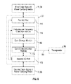
- FIG. 6 is a more detailed block diagram of one embodiment of a data collection and communication device or system
- FIG. 7 is a block diagram similar to FIG. 6 illustrating another embodiment of a data collection and communication device or system which includes environmental sensors and collection of environmental sensor data in addition to internal function and externally generated data;
- FIG. 8 is a functional block diagram of an embodiment of a data collecting and communication device incorporated in a connector signal communication circuit including an electro-optical media converter;
- FIG. 9 is a front elevation view of another embodiment of a subsea connector unit with an attached enclosure for containing a data collection and communication device;
- FIG. 10 is a front elevation view illustrating a modified termination shell of a subsea end connector unit incorporating a transponder for wireless communication connected to a data collection and communication device or circuit board inside the shell;
- FIG. 11 is a cross-section of the termination shell of FIG. 10 on the lines 11 - 11 of FIG. 10 , illustrating the circuit board and signal path from the transponder to the circuit board in more detail;
- FIG. 12 is a front elevation view of another embodiment of an end connector unit with a secondary connector containing a data collection and communication device or circuit and providing an extra data port or umbilical for an external instrument or data and communication system.
- Certain embodiments as disclosed herein provide for a subsea connector or connection point having an integral data gathering and communication system for collecting data on internal functions, environmental conditions, and external system components and communicating the collected data to a shore based monitoring station, a nearby subsea hub, or other monitoring facility.
- FIG. 1 illustrates one embodiment of a subsea communication system including a jumper cable 10 with subsea end connectors or units 12 at each end configured for connection to a mating connector unit at the end of a subsea cable 11
- FIGS. 2 and 3 illustrate one embodiment of an end connector or subsea connector 12 with an integral data collection and communication module or system in more detail.
- the end connectors may be electrical connectors, optical connectors, or electro-optical connectors and the cables 10 , 11 may be electrical Ethernet cables such as 10/100/1000BASE-T cables, optical cables, or electro-optical cables.
- Each cable has signal carrying media extending between opposite ends of the cable, such as optical fibers or electrical wires, or both fibers and wires, depending on the specific system requirements.
- signal carrying media refers to data and power carrying electrical wires or data carrying optical fibers.
- Optical or electro-optical Ethernet cables contain one or more Ethernet signal carrying optical fibers, which may be single mode or multi-mode fibers, along with two to four electrical power signal conductor wires (two of which may be redundant), and may comprise pressure balanced, oil-filled hose designed for subsea communications, such as an oil-filled hose or cable manufactured by Teledyne ODI, Inc. of Daytona Beach, Fla.
- FIGS. 2 and 3 illustrate one embodiment of the end connector units or subsea connectors 12 in more detail.
- each connector unit 12 comprises an outer housing having a first cable connector portion 14 having a cable input port 15 for receiving an end of cable 10 , a termination shell 17 connected to connector portion 14 , and a second cable connector portion or module 16 which has an open second end 19 and contains a subsea mateable connector unit or module 18 for releasable connection to a mating connector unit (not illustrated) at the end of cable 11 .
- An ROV grip 20 is secured to the housing or shell 16 , as seen in FIGS. 1 and 3 .
- Connector unit 18 is not shown in detail in FIGS.
- connector portion 16 comprises the outer shell or housing of such a plug or receptacle.
- contacts of the connector device are connected to one or more sets of signal and power carrying media (fibers or wires) forming signal paths through one or more sealed chambers in the end connector unit to the second cable input/output (I/O) port 15 , where they communicate with corresponding signal and power carrying media in cable 10 .
- signal and power carrying media fibers or wires
- end connector unit 12 is a modified end connector unit with an integral data collection and communication system or module 30 , 31 or 65 on a printed wiring board or circuit board mounted in chamber 32 inside termination shell 17 , with signal and power carrying media 34 (fibers, electrical wires, or both wires and fibers) extending from housing 16 via a penetrator or feed through (not illustrated) and connected to appropriate circuit input/output (I/O) junctions or ports of module 30 , 31 or 65 , and corresponding signal and power carrying media 35 from cable 10 extending into chamber 32 and also connected to appropriate circuit I/O junctions of module 30 , 31 or 65 .
- signal and power carrying media 34 fibers, electrical wires, or both wires and fibers
- data collection and communication system or circuit 30 , 31 or 65 is enclosed within a chamber 32 inside termination shell 17 which is sealed from the external subsea environment.
- the components of the data collection and communication system may be mounted on a single layer or multi-layer circuit board mounted on a rigid support platform or the like which may be secured to the reinforced walls of shell 17 in any suitable manner.
- the shell 17 is of high strength material and construction and is suitable for subsea use, and may be of similar construction to the walls of standard subsea equipment enclosures or housings.
- chamber 32 is a hermetically sealed atmospheric chamber which may be a one atmosphere chamber.
- the data collection and communication system or device 30 , 31 or 65 is mounted in a chamber within termination shell 17 in the embodiment of FIGS. 2 and 3 and the modified embodiment of FIGS. 10 and 11 , it may alternatively be mounted elsewhere within the connector unit or in an external shell 40 connected to connector unit 12 , as described in more detail below in connection with FIG. 9 , or in a secondary connector module 86 having an extra inlet/outlet port, as described in more detail below in connection with FIG. 12 . In all cases, the system 30 , 31 , or 65 is housed in a sealed subsea enclosure.
- the data collection and communication system or device is configured to detect and store both internal and external source operational status data (e.g. voltage, current, optical power and the like) from the incoming media via cables 11 and 10 , and may also be configured to collect data from local sensors regarding current environmental conditions.
- internal and external source operational status data e.g. voltage, current, optical power and the like
- all signal and power carrying media are routed to the data collection and communication system in the illustrated embodiment, only selected wires and/or fibers may be routed through system or circuit 30 , 31 or 65 in alternative embodiments.
- the collected system status and environmental conditions data is stored and subsequently transmitted to a remote land-based or offshore monitoring station or to a local hub for further processing either at periodic intervals or on demand, using bi-directional Ethernet, CANBUS, a carrier frequency system over the cable power lines, optical signal over optical fiber, or wireless communication links over short distances.
- FIG. 4 illustrates one embodiment of a CANBUS implementation of data collection and communication module 30 into a CANBUS repeater system.
- the incoming media 34 from cable 11 via connector 16 are connected to a first input/output (I/O) port 42 which has a bi-directional communication path via CANBUS with a CANBUS repeater 44 and a CANBUS capable microcontroller or microprocessor 45 which has data input capability.
- Media 35 in communication with cable 10 are connected to a second input/output (I/O) port 46 which communicates with CANBUS repeater 44 via a bi-directional CANBUS link.
- I/O input/output
- microprocessor 45 collects and stores system performance data which it acquires from the signal and power carrying media on cables 10 and 11 according to programmed instructions, such as internal source voltage, current and optical power 48 via jumper cable 10 and external source voltage, current and optical power 50 via cable 11 .
- the subsea optical CAN bus system described in U.S. Pat. App. Pub. No. 20140023365 may be used for conversion of electrical signals to optical signals carried along the optical or electro-optical jumper cable and vice versa, and the contents of U.S. Pat. App. Pub. No. 20140023365 are incorporated herein by reference in their entirety.
- the data collection and communication system 30 , 31 or 65 has separate electrical and optical data input/output ports for communication with electrical wires and optical fibers of the optical or electro-optical cable or cables.
- connector unit 12 is also modified to include various environmental sensors 52 , such as temperature sensors, pressure sensors, salinity sensors, and the like. Some sensors may be mounted on the exterior of the shell 16 or 17 to detect external environmental conditions, while one or more sensors may also be provided inside the connector housing if desired. The sensor outputs are suitably connected to associated data inputs of microprocessor 45 as schematically illustrated in FIGS. 4 and 7 .
- FIG. 5 illustrates a second embodiment of the data collection and communication device or system 30 or 31 in which data collection and communication capability is incorporated into an Ethernet capable microcontroller 54 .
- a first I/O port 55 is in communication with media 34 extending from connector shell 16
- a second I/O port 56 is in communication with media 35 connected from jumper cable 10 for signal communication between cables 11 and 10 .
- Port 55 communicates with port 56 via Ethernet switch 58 .
- a third I/O port 60 communicates with Ethernet switch 58 for input of monitoring data via the Ethernet switch 58 to microcontroller 54 .
- Data collected from environmental sensors 52 is also communicated to microcontroller 54 via respective sensor inputs or via port 60 .
- the collected data is stored in a suitable data storage module 62 and periodically communicated to a remote monitoring station via Ethernet switch 58 and cable 11 , and/or to a local hub via acoustic or optical transponder 82 , either at fixed intervals or on demand.
- collected monitoring data is saved in a data storage module 62 and may be transmitted to a remote on shore or off shore monitoring station or a local hub via the communications channel in the respective cable, either at predetermined intervals or on receipt of a data request from the monitoring station, and may also be transmitted to a local hub, ROV, submarine or the like via transponder 82 .
- the collected data is then processed to diagnose faults and determine whether maintenance is needed.
- the communication of collected data may be via Ethernet, CANBUS, carrier frequency over cable power lines, optical signal over optical fiber, or the like.
- FIG. 6 is a block diagram illustrating one embodiment of the data collection and communication system or device 30 in more detail.
- system 30 collects operational status data from the external source via signal and power carrying media in cable 11 and internal or local source data via signal and power carrying media in jumper cable 10 .
- FIG. 7 is a block diagram illustrating another embodiment of a data collection and communication system or device 31 which is configured to collect system operational data carried by the cables and also to collect sensor data from local environmental sensors.
- the system or device 30 has a first I/O port 110 which communicates with signal and power carrying media (wires or fibers, or both) in cable 11 and a second I/O port 112 which communicates with signal and power carrying media (wires or fibers, or both) in cable 10 .
- first I/O port 110 which communicates with signal and power carrying media (wires or fibers, or both) in cable 11
- second I/O port 112 which communicates with signal and power carrying media (wires or fibers, or both) in cable 10 .
- a performance parameter collection module 114 measures performance related data from the signals carried by the media, such as voltage, current, and/or optical pressure, and communicates the measured operating or performance parameters to data storage module 62 .
- a data communication module 115 is configured to transmit the stored performance parameters periodically or on demand to a system performance monitoring station, for example via the first cable 11 to a remote monitoring station which may be land-based, and/or via second cable 10 to a local hub.
- modules 114 , 62 and 115 may be provided by CANBUS capable microcontroller 45 of FIG. 4 or Ethernet capable microcontroller 54 of FIG. 5 , depending on whether the system is using a CANBUS or Ethernet arrangement for signal communication.
- system performance data may be transmitted via port 85 for wireless communication via transponder 82 , which may be mounted on the subsea connector shell, as described in more detail below in connection with the embodiment of FIGS. 10 and 11 .
- FIG. 7 illustrates a modified data collection and communication system 31 which adds a third I/O port 116 which communicates with one, two or more environmental sensors 52 mounted on or within the subsea connector 12 and is connected to environmental data collection module 118 .
- Sensors 52 may include a water temperature sensor, a water pressure sensor, a salinity sensor, or the like. Sensors may also be provided for monitoring pressure and temperature within the connector chamber or chambers.
- Environmental data collection module 118 receives sensor input signals and communicates the sensor data to the data storage module 62 for communication to the monitoring station together with the performance parameter data collected by module 114 .
- System 31 is otherwise identical to that of FIG. 6 , and like reference numbers are used for like parts as appropriate. Although modules 114 and 118 are shown separately in FIG.
- modules 114 , 118 , 62 and 115 may be incorporated in either CANBUS capable microcontroller 45 of FIG. 4 or Ethernet capable microcontroller 54 of FIG. 5 .
- an optional additional or fourth input/output port 85 is provided for wireless communication with a local monitoring station such as a local hub or ROV via transponder 82 , which may be an acoustical or optical transponder or other type of transponder, as also illustrated in FIG. 7 .
- each port may comprise two or more junctions, depending on the number of separate signal/power configuring wires or fibers are involved.
- FIG. 8 illustrates another embodiment of a circuit 65 including a data collection and communication system which may be built into a subsea connector or connector unit 12 in a similar manner to the systems 30 and 31 described above.
- the subsea connector is designed for bi-directional communication between subsea optical cables and electrical Ethernet cable 11 , for example as described in US Pat. App. Pub. No. 2013/0044983 referenced above, the contents of which are incorporated herein by reference.
- the connector unit of US Pat. App. Pub. 2013/0044984 includes a built-in, bi-directional optical/electrical media converter on a PWB (printed wiring board) for converting signals from the electrical cable into optical signals and vice versa.
- PWB printed wiring board
- FIG. 8 illustrates one embodiment of a modified optical/electrical media converter circuit 65 which may be installed at an appropriate location inside the connector or termination shell or in a suitable chamber inside the connector unit, for example as described in US Pat. App. Pub. No. 2013/0044983. As illustrated in FIG.
- single mode or multi-mode optical fiber or fibers 64 from cable 10 entering chamber 32 from an optical cable termination assembly are routed to an optical input/output (I/O) junction 66 of circuit 65
- electrical power wires 68 of optical cable 10 are routed to electrical I/O junction or port 70 which is connected to data and power inputs of microcontroller 143 .
- Electrical signal and power wires 72 from cable 11 extend to the second electrical I/O junction 74 of the media converter and data collection and communication circuit 65 .
- Outputs of any environmental sensors 52 installed inside or outside the connector unit 12 are connected to sensor data input/output port 75 of microprocessor 143 . Collected system and environmental monitoring data is stored in data storage module 62 .
- Circuit 65 converts electrical signals received at electrical I/O port or junction 74 of circuit 65 into optical signals transmitted at optical I/O port or junction 66 , and converts optical signals received at I/O port 66 into electrical signals at I/O port 74 .
- electrical signals received at port 74 are provided to data inputs of microcontroller 143
- electrical signals converted from optical signals received at port 66 are also provided by O-E converter chip 142 to data inputs of microprocessor 143 , as are electrical power inputs from the electrical input/output port 70 associated with cable 10 .
- ports or junctions 66 , 70 , 74 , and 75 are shown as single I/O junctions, it will be understood that two or more electrical I/O junctions and optical I/O junctions are provided in some embodiments, depending on the number of separate signal carrying wires and fibers and the number of separate sensor inputs.
- a controller area network (CAN) bus arrangement may be used for signal communications in circuit 65 .
- the circuit 65 basically comprises an optical transmitter and receiver 140 connected to the optical input/output port or junction 66 , a bi-directional optical/electrical converter module or chip 142 , and a microcontroller 143 which controls operation of the converter module 142 as well as collection and communication of data collected from the cable optical and electrical media and from the environmental sensors. Separate microcontrollers or microprocessors for the two functions may be provided in alternative embodiments.
- Quad transformer module 144 is connected to electrical input/output device 130 , which may be an RJ-45 connector in one embodiment.
- AC filter 145 which is followed by AC-DC converter 146 , and DC-DC converters 148 for the precise voltages needed by the module components, specifically the optical transmitter and receiver 140 , the converter chip 142 , and the microprocessor or microcontroller 143 .
- AC filter 145 and AC-DC converter 146 are omitted where the power supply is a DC supply voltage.
- Power supply for circuit 65 may alternatively be provided by power carrying wires of either the electrical or optical cables connected to the unit, and in this case the power carrying wires are connected to DC-DC converter 148 .
- the data collection and communication device or system of FIGS. 4 to 7 , or the modified media converter and data collection and communication circuit or system of FIG. 8 may be suitably mounted on a printed wiring board inside the existing connector or termination shell as illustrated in FIG. 3 .
- the printed wiring board carrying the data collection and communication system 30 or 31 or combined media converter and data collection and communication system 65 may be mounted in a chamber 76 inside an external, add-on housing or shell 40 , as illustrated in FIG. 9 .
- modified subsea connector 80 includes an additional shell 40 connected to the termination shell 17 between the shell output/input and cable 10 .
- Chamber 76 of shell 40 communicates with chamber 32 of shell 17 to provide more room for implementation of the various functions of the collection and communication module as well as any other functions to be included (such as the media converter of FIG. 8 ).
- the subsea connector 80 is otherwise identical to connector 12 of FIGS. 1-3 , and like reference numbers are used for like parts as appropriate.
- FIGS. 10 and 11 illustrate part of a modified connector unit 95 in which a transponder 82 such as an acoustic or optical transponder or hydrophone is mounted on the outside of termination shell 17 with signal wires 84 extending from the transponder into chamber 32 and connected to a transponder I/O port 85 of module 30 , 31 or 65 for bi-directional communication between the microprocessor 45 and a local monitoring station such as a nearby hub or a remotely operated vehicle (ROV) or submarine.
- Connector unit 95 is otherwise identical to the connector unit of FIGS. 1 to 3 , and like reference numbers are used for like parts as appropriate.
- a similar transponder I/O port may be provided in the Ethernet implemented system or circuit of any of FIG. 4 to FIG.
- Transponder 82 may be used for wireless communication (acoustic or optical communication or the like) over a short distance to a nearby platform, ROV, or submarine for two-way communication of system operational data or commands. Inductive coupling or radio links may alternatively be used over very short distances.
- modified connector unit 125 is equipped with a “piggy-back” connector unit 86 with a first input/output connection or port connected to cable 10 and a second input/output connector 88 for dry mate or wet mate connection to a local, external instrument or external data and communication system 90 .
- the function of the end connector unit 12 is expanded to have it serve as a communication access point and node.
- the external data and communication system may be secured to piggy-back connector unit via mateable dry mate connector portions or a feed through connector on the external system or equipment module 90 prior to subsea deployment of the connector unit. As illustrated in FIG.
- data collection and communication system 30 , 31 or 65 is mounted in an inner chamber of connector unit 86 with signal and power carrying media 34 extending out of termination shell 17 connected to an input/output port or ports of the data collection and communication system, and corresponding signal and power carrying media 35 extending from cable 10 to a second input/output port of system 30 , 31 or 65 .
- Data collected from the media 34 and 35 , and from any sensors (not illustrated) is communicated by media 92 to I/O connector 88 for communication with the external data and communication system 90 .
- the connector unit 12 , 80 , 95 or 125 in the foregoing embodiments may be provided at one end of cable 10 only, while the other end is terminated to a standard subsea optical connector or electro-optical hybrid connector or feed through fitting of a local subsea equipment housing.
- the electrical cable connector portion 16 and termination shell 17 are shown separately in FIGS. 1 to 3 , they may be formed as a single or unitary housing in alternative embodiments. Additionally, all three portions 14 , 17 and 16 may also be formed in a unitary housing in other embodiments, and the data collection and communication module or PWB may be mounted in that housing or an additional connector shell or housing connected to the main connector housing.
- Electrical connecter module 18 may be similar or identical to a standard subsea or wet mateable electrical plug or receptacle connector unit or module, for example a plug or receptacle connector unit as described in U.S. Pat. No. 5,645,442 or U.S. Pat. No. 5,171,158 of Cairns, or in U.S. Patent Application Publication No. 2011/0130024 of Cairns, the contents of each of which are incorporated herein by reference, or other such subsea electrical connector units.
- connector module 18 may be a standard subsea or wet mateable optical or electro-optical plug or receptacle connector unit, as described in U.S. Pat. No.
- Connector unit 18 is therefore designed for releasable connection to a mating, standard electrical, optical, or electro-optical receptacle or plug connector unit at the end of cable 11 .
- the number of electrical wires and/or optical fibers in cables connected to connector unit 18 may vary from two to twelve or more, depending on the application. Typically, one, two, or more electrical power carrying wires are included, with the remaining media carrying signals.
- the above embodiments implement monitoring of modern undersea communication and power systems at interconnect points or connections in such systems, to allow faults to be predicted or degradations in performance to be predicted on an ongoing basis, both to assure the validity of the connection and the function of a unit to which the connection is made.
- the addition of a data collection and communication module to gather such performance data and store the data for later communication to a remotely located or local system monitoring station converts the conventional subsea connector or subsea junction to a “smart” connector, potentially avoiding the need to send an ROV or the like to check such junctions and implement repairs after the fact, i.e. when a system failure has already occurred.
- the embodiments described above incorporate monitoring of both external and internal functions at the interconnect point, and optionally also incorporate monitoring of local environmental conditions, with collected data communication to a shore-based station or a nearby hub for fault prediction or performance degradation.
- This allows for remote or local monitoring of the system at one or more connector interfaces, and is beneficial for maintaining asset integrity or planning maintenance activity.
- There are many possible means for communication of the collected monitoring data to a monitoring station for example Ethernet, CANBUS, or some carrier frequency system over power lines, as well as an optical or acoustic transponder for local signal communication, or inductive coupling or radio links over very short distances.
- processors such as a general purpose processor, a multi-core processor, a digital signal processor (DSP), an application specific integrated circuit (ASIC), a field programmable gate array (FPGA) or other programmable logic device, discrete gate or transistor logic, discrete hardware components, or any combination thereof designed to perform the functions described herein.
- DSP digital signal processor
- ASIC application specific integrated circuit
- FPGA field programmable gate array
- a general-purpose processor can be a microprocessor, but in the alternative, the processor can be any processor, controller, microcontroller, or state machine.
- a processor can also be implemented as a combination of computing devices, for example, a combination of a DSP and a microprocessor, a plurality of microprocessors, one or more microprocessors in conjunction with a DSP core, or any other such configuration.
- a software module can reside in RAM memory, flash memory, ROM memory, EPROM memory, EEPROM memory, registers, hard disk, a removable disk, a CD-ROM, or any other form of storage medium.
- An exemplary storage medium can be coupled to the processor such that the processor can read information from, and write information to, the storage medium. In the alternative, the storage medium can be integral to the processor.
- the processor and the storage medium can reside in an ASIC.
- device, blocks, or modules that are described as coupled may be coupled via intermediary device, blocks, or modules.
- a first device may be described a transmitting data to (or receiving from) a second device when there are intermediary devices that couple the first and second device and also when the first device is unaware of the ultimate destination of the data.
Abstract
A subsea data collection and communication system is installed at a subsea interconnect point or subsea connector used for communication between subsea electrical, optical or hybrid electro-optical cables. The data collection and communication system is configured to collect system performance data such as voltage, current, optical pressure and the like from signals carried by the wires or fibers in cables connected to the connector unit, and may also collect data on environmental conditions from sensors installed in or on the connector unit, such as temperature, pressure, or sea water salinity sensors, and the like. The collected data is transmitted to a remote monitoring station or local hub for further processing to detect potential faults or performance degradation either at periodic intervals or on demand, using bi-directional Ethernet, CANBUS, a carrier frequency system over the cable power lines, optical signal over optical fiber, or wireless communication links over short distances.
Description
1. Field of the Invention
The present invention relates generally to connection of equipment used in subsea operations, such as equipment used in the subsea oil and gas industry as well as telecommunications, to shore-based stations or other remote systems, and is particularly concerned with a subsea electrical, optical, or electro-optical connector unit with a built-in data collection and communication system.
2. Related Art
There are many types of connectors for making electrical and fiber-optic cable connections in hostile or harsh environments, such as underwater or subsea electrical, optical and hybrid electrical and optical connectors which can be repeatedly mated and demated underwater at great ocean depths. The connectors may be electrical only, optical only, or may be hybrid electrical and optical connectors. These connectors typically consist of releasably mateable plug and receptacle units or connector parts, each attached to cables or other devices intended to be joined by the connectors to form completed circuits. Each connector unit contains one or more electrical and/or optical contacts or junctions for engagement with the junctions in the other unit when the two units are mated together. To completely isolate the contacts to be joined from the ambient environment, one or both parts of these connectors house the contacts in oil-filled, pressure-balanced chambers. One example of an electrical underwater pin and socket connector is described in U.S. Pat. No. 5,645,442 of Cairns and is sold by Teledyne ODI, Inc. of Daytona Beach, Fla. under the name Nautilus®.
Monitoring of modern undersea communication and power systems is needed in order to predict faults or diagnose degradation in performance of various system components. Land-based systems exist that can be used to connect a data or power port to verify or measure the presence of data or power at the port, but this data is monitored locally. There is no effective way to monitor subsea installations on an ongoing basis for early detection of potential faults or potential equipment failures.
Embodiments described herein provide a subsea data collection and communication system installed at a subsea interconnect point or connector unit used for communication between subsea electrical, optical or hybrid electro-optical cables or between a subsea cable and subsea equipment. The data collection and communication system may be built into the subsea connector and is configured to collect system performance data such as voltage, current, optical pressure and the like from the wires or fibers in cables connected to the connector unit, and may also collect data on environmental conditions from sensors installed in or on the connector unit, such as temperature, pressure, sea water salinity, and the like. The collected data is transmitted to a remote monitoring station or local hub for further processing either at periodic intervals or on demand, using bi-directional Ethernet, CANBUS, a carrier frequency system over the cable power lines, optical signal over optical fiber, or optical, acoustical or other wireless communication links over short distances.
According to one aspect, a subsea end connector with an integral data collection and communication module or system is provided which has a first port configured for connection to a first subsea cable and a second port configured for connection to a second cable which may be another subsea cable or jumper cable. The subsea connector includes a single or multi-part outer shell or housing having one or more internal chambers. A data collection and communication system with data input/output ports is installed in an internal chamber of the connector housing or an additional housing or connector unit secured to the connector housing, and communicates with signal carrying media (wires or fibers) of the end connector unit to collect and store monitoring data from signals and power carried on the cable media (wires, fibers, or both), such as internal and external voltage, current, optical pressure, and the like. In one embodiment, the system may include various environmental sensors which may be incorporated inside or outside the connector shell or housing and connected to an input of the data collection and communication system, which also collects and stores environmental data from the sensors such as temperature, water pressure, salinity, and the like. Collected data may be communicated over the cable or cables or by other means to a remote, onshore or offshore monitoring station or a local hub in order to predict faults or diagnose degradation in performance of various system components, and to determine if maintenance is needed.
In one embodiment, the data collection and communication system has one or more first input/output (I/O) ports communicating with one or more signal or power carrying media such as wires or fibers in a first cable connected to the connector unit and one or more second I/O ports communicating with one or more signal or power carrying media such as wires or fibers in a second cable connected to the connector unit, and may also have one or more I/O ports for receiving data from environmental sensors associated with the connector unit. Collected monitoring data may be communicated to a remote monitoring station for processing via the I/O ports to one of the existing cables connected to the end connector unit. Additionally or alternatively, collected data may be communicated via an optical or acoustical transponder for wireless communication over short distances to a nearby platform, an ROV (Remote Operated Vehicle), a submarine, or the like.
This invention provides a subsea “smart” connector with a built-in data collection and communication device or system. This allows easy local monitoring of subsea communication and power systems at one or more subsea connector interfaces in order to predict faults or diagnose degradation in performance of various system components, so that appropriate maintenance can be carried out. The system may include sensors for monitoring local environmental conditions such as temperature, pressure, salinity, and the like with outputs connected to the data collection and communication system for collection, storage, and subsequent communication to a monitoring station.
The details of the present invention, both as to its structure and operation, may be gleaned in part by study of the accompanying drawings, in which like reference numerals refer to like parts, and in which:
Certain embodiments as disclosed herein provide for a subsea connector or connection point having an integral data gathering and communication system for collecting data on internal functions, environmental conditions, and external system components and communicating the collected data to a shore based monitoring station, a nearby subsea hub, or other monitoring facility.
After reading this description it will become apparent to one skilled in the art how to implement the invention in various alternative embodiments and alternative applications. However, although various embodiments of the present invention will be described herein, it is understood that these embodiments are presented by way of example only, and not limitation. As such, this detailed description of various alternative embodiments should not be construed to limit the scope or breadth of the present invention.
In the embodiment of FIGS. 2 and 3 , data collection and communication system or circuit 30, 31 or 65 is enclosed within a chamber 32 inside termination shell 17 which is sealed from the external subsea environment. The components of the data collection and communication system may be mounted on a single layer or multi-layer circuit board mounted on a rigid support platform or the like which may be secured to the reinforced walls of shell 17 in any suitable manner. The shell 17 is of high strength material and construction and is suitable for subsea use, and may be of similar construction to the walls of standard subsea equipment enclosures or housings. In one embodiment, chamber 32 is a hermetically sealed atmospheric chamber which may be a one atmosphere chamber.
Although the data collection and communication system or device 30, 31 or 65 is mounted in a chamber within termination shell 17 in the embodiment of FIGS. 2 and 3 and the modified embodiment of FIGS. 10 and 11 , it may alternatively be mounted elsewhere within the connector unit or in an external shell 40 connected to connector unit 12, as described in more detail below in connection with FIG. 9 , or in a secondary connector module 86 having an extra inlet/outlet port, as described in more detail below in connection with FIG. 12 . In all cases, the system 30, 31, or 65 is housed in a sealed subsea enclosure.
As discussed in more detail below in connection with FIGS. 4 to 8 , the data collection and communication system or device is configured to detect and store both internal and external source operational status data (e.g. voltage, current, optical power and the like) from the incoming media via cables 11 and 10, and may also be configured to collect data from local sensors regarding current environmental conditions. Although all signal and power carrying media are routed to the data collection and communication system in the illustrated embodiment, only selected wires and/or fibers may be routed through system or circuit 30, 31 or 65 in alternative embodiments. The collected system status and environmental conditions data is stored and subsequently transmitted to a remote land-based or offshore monitoring station or to a local hub for further processing either at periodic intervals or on demand, using bi-directional Ethernet, CANBUS, a carrier frequency system over the cable power lines, optical signal over optical fiber, or wireless communication links over short distances.
In one embodiment, where the cables are fiber optic or hybrid electro-optical cables, the subsea optical CAN bus system described in U.S. Pat. App. Pub. No. 20140023365 may be used for conversion of electrical signals to optical signals carried along the optical or electro-optical jumper cable and vice versa, and the contents of U.S. Pat. App. Pub. No. 20140023365 are incorporated herein by reference in their entirety. In this alternative, it will be understood that the data collection and communication system 30, 31 or 65 has separate electrical and optical data input/output ports for communication with electrical wires and optical fibers of the optical or electro-optical cable or cables.
In one embodiment, connector unit 12 is also modified to include various environmental sensors 52, such as temperature sensors, pressure sensors, salinity sensors, and the like. Some sensors may be mounted on the exterior of the shell 16 or 17 to detect external environmental conditions, while one or more sensors may also be provided inside the connector housing if desired. The sensor outputs are suitably connected to associated data inputs of microprocessor 45 as schematically illustrated in FIGS. 4 and 7 .
In both the CANBUS and Ethernet systems described above, collected monitoring data is saved in a data storage module 62 and may be transmitted to a remote on shore or off shore monitoring station or a local hub via the communications channel in the respective cable, either at predetermined intervals or on receipt of a data request from the monitoring station, and may also be transmitted to a local hub, ROV, submarine or the like via transponder 82. The collected data is then processed to diagnose faults and determine whether maintenance is needed. The communication of collected data may be via Ethernet, CANBUS, carrier frequency over cable power lines, optical signal over optical fiber, or the like.
As illustrated in FIG. 6 , the system or device 30 has a first I/O port 110 which communicates with signal and power carrying media (wires or fibers, or both) in cable 11 and a second I/O port 112 which communicates with signal and power carrying media (wires or fibers, or both) in cable 10. For electro-optical cables and optical cables with one or more electrical power carrying wires, separate electrical and optical I/O ports are provided. A performance parameter collection module 114 measures performance related data from the signals carried by the media, such as voltage, current, and/or optical pressure, and communicates the measured operating or performance parameters to data storage module 62. A data communication module 115 is configured to transmit the stored performance parameters periodically or on demand to a system performance monitoring station, for example via the first cable 11 to a remote monitoring station which may be land-based, and/or via second cable 10 to a local hub. In FIG. 6 , modules 114, 62 and 115 may be provided by CANBUS capable microcontroller 45 of FIG. 4 or Ethernet capable microcontroller 54 of FIG. 5 , depending on whether the system is using a CANBUS or Ethernet arrangement for signal communication. Additionally, system performance data may be transmitted via port 85 for wireless communication via transponder 82, which may be mounted on the subsea connector shell, as described in more detail below in connection with the embodiment of FIGS. 10 and 11 .
Although the various I/O ports in the systems of FIGS. 4 to 7 are shown as single I/O junctions, it will be understood that each port may comprise two or more junctions, depending on the number of separate signal/power configuring wires or fibers are involved.
The circuit 65 basically comprises an optical transmitter and receiver 140 connected to the optical input/output port or junction 66, a bi-directional optical/electrical converter module or chip 142, and a microcontroller 143 which controls operation of the converter module 142 as well as collection and communication of data collected from the cable optical and electrical media and from the environmental sensors. Separate microcontrollers or microprocessors for the two functions may be provided in alternative embodiments. Quad transformer module 144 is connected to electrical input/output device 130, which may be an RJ-45 connector in one embodiment. An AC power supply (not illustrated) is connected to AC filter 145 which is followed by AC-DC converter 146, and DC-DC converters 148 for the precise voltages needed by the module components, specifically the optical transmitter and receiver 140, the converter chip 142, and the microprocessor or microcontroller 143. AC filter 145 and AC-DC converter 146 are omitted where the power supply is a DC supply voltage. Power supply for circuit 65 may alternatively be provided by power carrying wires of either the electrical or optical cables connected to the unit, and in this case the power carrying wires are connected to DC-DC converter 148.
The data collection and communication device or system of FIGS. 4 to 7 , or the modified media converter and data collection and communication circuit or system of FIG. 8 , may be suitably mounted on a printed wiring board inside the existing connector or termination shell as illustrated in FIG. 3 . Alternatively, the printed wiring board carrying the data collection and communication system 30 or 31 or combined media converter and data collection and communication system 65 may be mounted in a chamber 76 inside an external, add-on housing or shell 40, as illustrated in FIG. 9 . In FIG. 9 , modified subsea connector 80 includes an additional shell 40 connected to the termination shell 17 between the shell output/input and cable 10. Chamber 76 of shell 40 communicates with chamber 32 of shell 17 to provide more room for implementation of the various functions of the collection and communication module as well as any other functions to be included (such as the media converter of FIG. 8 ). The subsea connector 80 is otherwise identical to connector 12 of FIGS. 1-3 , and like reference numbers are used for like parts as appropriate.
In the alternative embodiment of FIG. 12 , modified connector unit 125 is equipped with a “piggy-back” connector unit 86 with a first input/output connection or port connected to cable 10 and a second input/output connector 88 for dry mate or wet mate connection to a local, external instrument or external data and communication system 90. In this case, the function of the end connector unit 12 is expanded to have it serve as a communication access point and node. In one embodiment, the external data and communication system may be secured to piggy-back connector unit via mateable dry mate connector portions or a feed through connector on the external system or equipment module 90 prior to subsea deployment of the connector unit. As illustrated in FIG. 12 , data collection and communication system 30, 31 or 65 is mounted in an inner chamber of connector unit 86 with signal and power carrying media 34 extending out of termination shell 17 connected to an input/output port or ports of the data collection and communication system, and corresponding signal and power carrying media 35 extending from cable 10 to a second input/output port of system 30, 31 or 65. Data collected from the media 34 and 35, and from any sensors (not illustrated) is communicated by media 92 to I/O connector 88 for communication with the external data and communication system 90.
The connector unit 12, 80, 95 or 125 in the foregoing embodiments may be provided at one end of cable 10 only, while the other end is terminated to a standard subsea optical connector or electro-optical hybrid connector or feed through fitting of a local subsea equipment housing. Although the electrical cable connector portion 16 and termination shell 17 are shown separately in FIGS. 1 to 3 , they may be formed as a single or unitary housing in alternative embodiments. Additionally, all three portions 14, 17 and 16 may also be formed in a unitary housing in other embodiments, and the data collection and communication module or PWB may be mounted in that housing or an additional connector shell or housing connected to the main connector housing.
The number of electrical wires and/or optical fibers in cables connected to connector unit 18 may vary from two to twelve or more, depending on the application. Typically, one, two, or more electrical power carrying wires are included, with the remaining media carrying signals.
The above embodiments implement monitoring of modern undersea communication and power systems at interconnect points or connections in such systems, to allow faults to be predicted or degradations in performance to be predicted on an ongoing basis, both to assure the validity of the connection and the function of a unit to which the connection is made. The addition of a data collection and communication module to gather such performance data and store the data for later communication to a remotely located or local system monitoring station converts the conventional subsea connector or subsea junction to a “smart” connector, potentially avoiding the need to send an ROV or the like to check such junctions and implement repairs after the fact, i.e. when a system failure has already occurred. The embodiments described above incorporate monitoring of both external and internal functions at the interconnect point, and optionally also incorporate monitoring of local environmental conditions, with collected data communication to a shore-based station or a nearby hub for fault prediction or performance degradation. This allows for remote or local monitoring of the system at one or more connector interfaces, and is beneficial for maintaining asset integrity or planning maintenance activity. There are many possible means for communication of the collected monitoring data to a monitoring station, for example Ethernet, CANBUS, or some carrier frequency system over power lines, as well as an optical or acoustic transponder for local signal communication, or inductive coupling or radio links over very short distances.
In the past, an ROV was necessary in order to check the presence of data or power on a one time basis at an interconnect point in a subsea system. In the foregoing embodiments, the presence of data and power as well as the local environmental conditions can be monitored remotely as well as locally on an ongoing basis.
Those of skill will appreciate that the various illustrative logical blocks, modules, units, and algorithm steps described in connection with the embodiments disclosed herein can often be implemented as electronic hardware, computer software, or combinations of both. To clearly illustrate this interchangeability of hardware and software, various illustrative components, blocks, modules, and steps have been described above generally in terms of their functionality. Whether such functionality is implemented as hardware or software depends upon the particular constraints imposed on the overall system. Skilled persons can implement the described functionality in varying ways for each particular system, but such implementation decisions should not be interpreted as causing a departure from the scope of the invention. In addition, the grouping of functions within a unit, module, block, or step is for ease of description. Specific functions or steps can be moved from one unit, module, or block without departing from the invention.
The various illustrative logical blocks, units, steps and modules described in connection with the embodiments disclosed herein can be implemented or performed with a processor, such as a general purpose processor, a multi-core processor, a digital signal processor (DSP), an application specific integrated circuit (ASIC), a field programmable gate array (FPGA) or other programmable logic device, discrete gate or transistor logic, discrete hardware components, or any combination thereof designed to perform the functions described herein. A general-purpose processor can be a microprocessor, but in the alternative, the processor can be any processor, controller, microcontroller, or state machine. A processor can also be implemented as a combination of computing devices, for example, a combination of a DSP and a microprocessor, a plurality of microprocessors, one or more microprocessors in conjunction with a DSP core, or any other such configuration.
The steps of a method or algorithm and the processes of a block or module described in connection with the embodiments disclosed herein can be embodied directly in hardware, in a software module executed by a processor, or in a combination of the two. A software module can reside in RAM memory, flash memory, ROM memory, EPROM memory, EEPROM memory, registers, hard disk, a removable disk, a CD-ROM, or any other form of storage medium. An exemplary storage medium can be coupled to the processor such that the processor can read information from, and write information to, the storage medium. In the alternative, the storage medium can be integral to the processor. The processor and the storage medium can reside in an ASIC. Additionally, device, blocks, or modules that are described as coupled may be coupled via intermediary device, blocks, or modules. Similarly, a first device may be described a transmitting data to (or receiving from) a second device when there are intermediary devices that couple the first and second device and also when the first device is unaware of the ultimate destination of the data.
The above description of the disclosed embodiments is provided to enable any person skilled in the art to make or use the invention. Various modifications to these embodiments will be readily apparent to those skilled in the art, and the generic principles described herein can be applied to other embodiments without departing from the spirit or scope of the invention. Thus, it is to be understood that the description and drawings presented herein represent a presently preferred embodiment of the invention and are therefore representative of the subject matter which is broadly contemplated by the present invention. It is further understood that the scope of the present invention fully encompasses other embodiments that may become obvious to those skilled in the art and that the scope of the present invention is accordingly limited by nothing other than the appended claims.
Claims (16)
1. A subsea connector, comprising:
a single or multi-part connector housing having a first cable inlet port configured for selected connection to the end of a first, subsea cable and a second port configured for connection to a second cable;
first signal carrying media extending from the first cable inlet port into the connector housing for communication with second signal carrying media in the second cable via the second port;
a data collection and communication system located in the connector housing and configured to collect and store one or more predetermined performance parameters of the signals carried by said first and second signal carrying media, the system having a first input/output port communicating with at least some of the signal carrying media extending from the first cable inlet port, a second input/output port communicating with at least some of the signal carrying media in the second cable, and a microprocessor connected to said first and second input/output ports, the microprocessor comprising a data collection module configured for detecting and collecting predetermined parameters of the signals, a data storage module configured for storing said predetermined performance parameters, and a data communication module configured for communicating said stored performance parameters to a monitoring station; and
a transponder externally mounted on said connector housing, the data communication module having a third input/output port communicatively connected to said transponder and configured for wireless communication with a local monitoring device in the vicinity of said connector housing for receiving commands from said local monitoring device and sending collected system performance parameters to said local monitoring device.
2. The subsea connector of claim 1 , wherein the data communication module is communicatively connected to at least one of said cable input/output ports for communicating stored performance parameters to said monitoring station via signal carrying media of said first or second cable.
3. The subsea connector claim 1 , further comprising at least one sensor for monitoring a selected environmental parameter inside or outside the connector housing, the sensor having an output in communication with said data collection and communication system.
4. The subsea connector of claim 3 , comprising a plurality of sensors associated with said connector housing for monitoring different external or internal environmental parameters, the sensors having outputs and the data collection and communication system further comprising an environmental data collection module communicating with said sensor outputs and providing collected sensor output data to said data storage module, said data communication module being further configured to communicate stored environmental data to said monitoring station.
5. The subsea connector of claim 4 , wherein said sensors comprise at least a subsea temperature sensor and a subsea pressure sensor.
6. The subsea connector of claim 1 , wherein said at least one or more predetermined performance parameters comprises a plurality of performance parameters selected from the group consisting of voltage, current and optical pressure.
7. The subsea connector of claim 1 , wherein said connector housing comprises at least a first housing portion containing a subsea mateable receptacle or plug unit for releasable connection to a mating plug or receptacle unit at the end of the first subsea cable, and a termination shell connected between said first housing portion and said second port, and the data collection and communication module is mounted in said termination shell.
8. The subsea connector of claim 1 , wherein said connector housing comprises a first housing portion containing a subsea mateable receptacle or plug unit for releasable connection to a mating plug or receptacle unit at the end of the first subsea cable via said first input, a termination shell connected to said first housing portion, and an additional external shell connected between the termination shell and the second cable, and the data collection and communication module is mounted in said external shell.
9. The subsea connector of claim 1 , wherein said connector housing has at least a first connector housing and a second connector housing between said first and second cables, the second connector housing includes said second port and a third port configured for connection to an external data and communication system, said data collection and communication module is mounted in said second connector housing, performance parameter data carrying media extend from said data communication module to said third port, and said second signal carrying media extend from said second input/output port of said data collection and communication module to said second port of the second connector housing.
10. The subsea connector of claim 9 , wherein said third port comprises a dry mate or wet mate connector.
11. The subsea connector of claim 1 , wherein said signal carrying media comprise both data signal and power carrying media.
12. The subsea connector of claim 1 , wherein the first signal carrying media comprise one or more electrical conductors, and the second signal carrying media comprise one or more electrical conductors.
13. The subsea connector of claim 1 , wherein the first signal carrying media comprise one or more optical fibers, the second signal carrying media comprises one or more optical fibers, and the data collection and communication system is configured to pass the signals between said first and second input/output ports using a controller area network (CAN) bus protocol.
14. The subsea connector of claim 1 , wherein the data collection and communication system is configured to pass the signals between the first and second input/output ports using at least one of Modbus protocol, RS-232 standard, and RS-485 standard.
15. The subsea connector of claim 1 , wherein the first signal carrying media comprise one or more electrical conductors, at least some of the second signal carrying media comprise optical fibers, and the data collection and communication system further comprises a converter module configured to convert optical signals traveling on the optical fibers to/from electrical signals traveling on the electrical conductors.
16. The subsea connector of claim 1 , wherein the data collection and communication system is further configured to perform at least one function of switching, repeating, formatting, and multiplexing of data signals.
Priority Applications (4)
| Application Number | Priority Date | Filing Date | Title |
|---|---|---|---|
| US14/453,504 US9820017B2 (en) | 2014-08-06 | 2014-08-06 | Subsea connector with data collection and communication system and method |
| EP15745671.6A EP3177954A1 (en) | 2014-08-06 | 2015-07-17 | Subsea connector with data collection and communication system and method |
| JP2016575723A JP2017535019A (en) | 2014-08-06 | 2015-07-17 | Submarine connector having data collection and communication system and method |
| PCT/US2015/041007 WO2016022272A1 (en) | 2014-08-06 | 2015-07-17 | Subsea connector with data collection and communication system and method |
Applications Claiming Priority (1)
| Application Number | Priority Date | Filing Date | Title |
|---|---|---|---|
| US14/453,504 US9820017B2 (en) | 2014-08-06 | 2014-08-06 | Subsea connector with data collection and communication system and method |
Publications (2)
| Publication Number | Publication Date |
|---|---|
| US20160044390A1 US20160044390A1 (en) | 2016-02-11 |
| US9820017B2 true US9820017B2 (en) | 2017-11-14 |
Family
ID=53776981
Family Applications (1)
| Application Number | Title | Priority Date | Filing Date |
|---|---|---|---|
| US14/453,504 Active 2036-03-27 US9820017B2 (en) | 2014-08-06 | 2014-08-06 | Subsea connector with data collection and communication system and method |
Country Status (4)
| Country | Link |
|---|---|
| US (1) | US9820017B2 (en) |
| EP (1) | EP3177954A1 (en) |
| JP (1) | JP2017535019A (en) |
| WO (1) | WO2016022272A1 (en) |
Cited By (3)
| Publication number | Priority date | Publication date | Assignee | Title |
|---|---|---|---|---|
| US20170359128A1 (en) * | 2016-06-14 | 2017-12-14 | Teledyne Instruments, Inc. | Long distance subsea can bus distribution system |
| GB201918323D0 (en) | 2019-12-12 | 2020-01-29 | Siemens Ag | Subsea connector |
| US10928435B2 (en) | 2019-07-15 | 2021-02-23 | The Boeing Company | Electrical fault detector and method of use |
Families Citing this family (11)
| Publication number | Priority date | Publication date | Assignee | Title |
|---|---|---|---|---|
| US20170351036A1 (en) * | 2014-11-06 | 2017-12-07 | Ge Oil & Gas Uk Limited | Wet mate fiber optic connector |
| US9832549B2 (en) * | 2016-03-14 | 2017-11-28 | Teledyne Instruments, Inc. | System, method, and apparatus for subsea optical to electrical distribution |
| US10132155B2 (en) * | 2016-12-02 | 2018-11-20 | Onesubsea Ip Uk Limited | Instrumented subsea flowline jumper connector |
| US11346205B2 (en) | 2016-12-02 | 2022-05-31 | Onesubsea Ip Uk Limited | Load and vibration monitoring on a flowline jumper |
| FR3065120B1 (en) * | 2017-04-10 | 2019-06-21 | Dcns Energies | SYSTEM FOR CONNECTING UNDERWATER CABLES |
| NO20171010A1 (en) * | 2017-06-21 | 2018-09-10 | B&B Parken As | Auxiliary equipment for hand-held communication radio |
| DE102017220142A1 (en) * | 2017-11-13 | 2019-05-16 | Robert Bosch Gmbh | Test device for a connector, control unit, control system |
| US20190204467A1 (en) * | 2017-12-31 | 2019-07-04 | Power Monitors, Inc. | Method and Apparatus for a Cloud-Based Oil Well Monitoring System |
| EP4095578A1 (en) | 2021-05-26 | 2022-11-30 | Nexans | Fiber optic split and quick connecting device for submarine cables |
| CN115397045A (en) * | 2022-08-30 | 2022-11-25 | 龚洪雄 | Dual-communication adaptive industrial Internet of things terminal |
| CN115580790B (en) * | 2022-09-23 | 2023-06-23 | 杭州瀚陆信息技术有限公司 | Marine environment monitoring system based on Internet |
Citations (19)
| Publication number | Priority date | Publication date | Assignee | Title |
|---|---|---|---|---|
| EP0332622A1 (en) | 1986-11-11 | 1989-09-20 | Myrmidon Subsea Controls Ltd | Subsea systems and devices. |
| US5171158A (en) | 1990-04-11 | 1992-12-15 | Cairns James L | Underwater multiple contact electrical connector |
| US5645442A (en) | 1995-01-19 | 1997-07-08 | Ocean Design, Inc. | Sealed, Fluid-filled electrical connector |
| US6017227A (en) | 1996-03-07 | 2000-01-25 | Ocean Design, Inc. | Underwater connector |
| US6315461B1 (en) | 1999-10-14 | 2001-11-13 | Ocean Design, Inc. | Wet mateable connector |
| US6332787B1 (en) | 2000-08-18 | 2001-12-25 | Ocean Design, Inc. | Wet-mateable electro-optical connector |
| US20050213649A1 (en) * | 2004-03-12 | 2005-09-29 | Green Maurice D | Underwater data communication and instrument release management system |
| US20090204310A1 (en) * | 2008-02-08 | 2009-08-13 | Gittere Robert J | Portable, Palm-Sized Data Acquisition System for Use in Internal Combustion Engines and Industry |
| US20100089943A1 (en) * | 2006-10-07 | 2010-04-15 | Volker Till | Method of storing beer kegs and dispensing beer in a commercial bar or restaurant, a method of storing beverage barrels in a commercial bar or restaurant, and an apparatus therefor |
| US20100202463A1 (en) * | 2006-08-17 | 2010-08-12 | Gerald Ian Robinson | Communications system for an underwater fluid extraction facility |
| US20110130024A1 (en) | 2009-11-11 | 2011-06-02 | Teledyne Odi, Inc. | Keyless harsh environment connector |
| US20110280538A1 (en) * | 2010-05-17 | 2011-11-17 | Advanced Fiber Products, LLC | Pressure Resistant Media Converter Apparatus |
| US20120120963A1 (en) * | 2008-12-18 | 2012-05-17 | Vetco Gray Controls Ltd. | Subsea electronic module |
| US20130046299A1 (en) * | 2011-08-18 | 2013-02-21 | John J. Newkirk | Intelligent electrosurgical electrode and tracking system |
| US20130044983A1 (en) | 2011-08-19 | 2013-02-21 | Teledyne Instruments, Inc. | Subsea electro-optical connector unit for electro-optical ethernet transmission system |
| US20130225069A1 (en) * | 2010-11-05 | 2013-08-29 | Brupat Limited | Anchor Data Communication System |
| WO2013177685A1 (en) | 2012-05-30 | 2013-12-05 | Reflex Photonics Inc. | Optical connector monitoring |
| US20140023365A1 (en) | 2012-07-17 | 2014-01-23 | Teledyne Instruments, Inc. | Systems and methods for subsea optical can buses |
| US20140093247A1 (en) | 2012-10-01 | 2014-04-03 | Endre Fosso Jamtveit | Subsea Cable Termination Assembly, Subsea Connector and Method |
Family Cites Families (1)
| Publication number | Priority date | Publication date | Assignee | Title |
|---|---|---|---|---|
| KR101016179B1 (en) | 2010-05-01 | 2011-02-24 | (주)엠이엘 | Thermal compensation composition of optical fiber connector containing a fiber bragg grating |
-
2014
- 2014-08-06 US US14/453,504 patent/US9820017B2/en active Active
-
2015
- 2015-07-17 WO PCT/US2015/041007 patent/WO2016022272A1/en active Application Filing
- 2015-07-17 EP EP15745671.6A patent/EP3177954A1/en not_active Withdrawn
- 2015-07-17 JP JP2016575723A patent/JP2017535019A/en active Pending
Patent Citations (19)
| Publication number | Priority date | Publication date | Assignee | Title |
|---|---|---|---|---|
| EP0332622A1 (en) | 1986-11-11 | 1989-09-20 | Myrmidon Subsea Controls Ltd | Subsea systems and devices. |
| US5171158A (en) | 1990-04-11 | 1992-12-15 | Cairns James L | Underwater multiple contact electrical connector |
| US5645442A (en) | 1995-01-19 | 1997-07-08 | Ocean Design, Inc. | Sealed, Fluid-filled electrical connector |
| US6017227A (en) | 1996-03-07 | 2000-01-25 | Ocean Design, Inc. | Underwater connector |
| US6315461B1 (en) | 1999-10-14 | 2001-11-13 | Ocean Design, Inc. | Wet mateable connector |
| US6332787B1 (en) | 2000-08-18 | 2001-12-25 | Ocean Design, Inc. | Wet-mateable electro-optical connector |
| US20050213649A1 (en) * | 2004-03-12 | 2005-09-29 | Green Maurice D | Underwater data communication and instrument release management system |
| US20100202463A1 (en) * | 2006-08-17 | 2010-08-12 | Gerald Ian Robinson | Communications system for an underwater fluid extraction facility |
| US20100089943A1 (en) * | 2006-10-07 | 2010-04-15 | Volker Till | Method of storing beer kegs and dispensing beer in a commercial bar or restaurant, a method of storing beverage barrels in a commercial bar or restaurant, and an apparatus therefor |
| US20090204310A1 (en) * | 2008-02-08 | 2009-08-13 | Gittere Robert J | Portable, Palm-Sized Data Acquisition System for Use in Internal Combustion Engines and Industry |
| US20120120963A1 (en) * | 2008-12-18 | 2012-05-17 | Vetco Gray Controls Ltd. | Subsea electronic module |
| US20110130024A1 (en) | 2009-11-11 | 2011-06-02 | Teledyne Odi, Inc. | Keyless harsh environment connector |
| US20110280538A1 (en) * | 2010-05-17 | 2011-11-17 | Advanced Fiber Products, LLC | Pressure Resistant Media Converter Apparatus |
| US20130225069A1 (en) * | 2010-11-05 | 2013-08-29 | Brupat Limited | Anchor Data Communication System |
| US20130046299A1 (en) * | 2011-08-18 | 2013-02-21 | John J. Newkirk | Intelligent electrosurgical electrode and tracking system |
| US20130044983A1 (en) | 2011-08-19 | 2013-02-21 | Teledyne Instruments, Inc. | Subsea electro-optical connector unit for electro-optical ethernet transmission system |
| WO2013177685A1 (en) | 2012-05-30 | 2013-12-05 | Reflex Photonics Inc. | Optical connector monitoring |
| US20140023365A1 (en) | 2012-07-17 | 2014-01-23 | Teledyne Instruments, Inc. | Systems and methods for subsea optical can buses |
| US20140093247A1 (en) | 2012-10-01 | 2014-04-03 | Endre Fosso Jamtveit | Subsea Cable Termination Assembly, Subsea Connector and Method |
Non-Patent Citations (1)
| Title |
|---|
| International Search Report and Written Opinion for related international application No. PCT/US2015/041007 dated Oct. 26, 2015 in 10 pages. |
Cited By (5)
| Publication number | Priority date | Publication date | Assignee | Title |
|---|---|---|---|---|
| US20170359128A1 (en) * | 2016-06-14 | 2017-12-14 | Teledyne Instruments, Inc. | Long distance subsea can bus distribution system |
| US10727954B2 (en) * | 2016-06-14 | 2020-07-28 | Teledyne Instruments, Inc. | Long distance subsea can bus distribution system |
| US10928435B2 (en) | 2019-07-15 | 2021-02-23 | The Boeing Company | Electrical fault detector and method of use |
| GB201918323D0 (en) | 2019-12-12 | 2020-01-29 | Siemens Ag | Subsea connector |
| WO2021116323A1 (en) | 2019-12-12 | 2021-06-17 | Siemens Aktiengesellschaft | Subsea connector |
Also Published As
| Publication number | Publication date |
|---|---|
| WO2016022272A1 (en) | 2016-02-11 |
| EP3177954A1 (en) | 2017-06-14 |
| JP2017535019A (en) | 2017-11-24 |
| US20160044390A1 (en) | 2016-02-11 |
Similar Documents
| Publication | Publication Date | Title |
|---|---|---|
| US9820017B2 (en) | Subsea connector with data collection and communication system and method | |
| US10727954B2 (en) | Long distance subsea can bus distribution system | |
| EP2745156B1 (en) | Subsea electro-optical connector unit for electro-optical ethernet transmission system | |
| US9979491B2 (en) | Subsea power-over-fiber can bus converter | |
| US9858810B2 (en) | Arrangement and method for controlling and/or monitoring a subsea device | |
| Chave et al. | Cabled ocean observatory systems | |
| JP2017535019A5 (en) | ||
| CN105051325A (en) | Communications systems and methods for subsea processors | |
| JP2008141785A (en) | Network documentation system with electronic modules | |
| US9832549B2 (en) | System, method, and apparatus for subsea optical to electrical distribution | |
| AU2021272086B2 (en) | Self-insulating high bandwidth connector | |
| US20180337737A1 (en) | Communication system network | |
| CN110753781B (en) | Underwater power and communication module | |
| CN101512983A (en) | Routing facilities for seabed electronic module | |
| WO2020242318A1 (en) | Subsea node for docking underwater intervention drones, method and system | |
| US10030462B2 (en) | Control and supply unit | |
| Lentz | New applications for submarine cables | |
| WO2017071844A1 (en) | Communication device, subsea communication system and monitoring method for a subsea application | |
| EP3369143B1 (en) | Data switch for underwater use | |
| US8540016B2 (en) | Control and supply unit | |
| Thomas et al. | Technology in undersea cable systems: 50 years of progress | |
| Shaheen et al. | ROV serviceable science node for cabled ocean observatories | |
| Greene | Opening opportunities in subsea communications | |
| Ramesh et al. | Fault-tolerant control network architecture of deep water Manned submersible MATSYA 6000 | |
| RU132936U1 (en) | ACTIVE FIBER OPTICAL CABLE |
Legal Events
| Date | Code | Title | Description |
|---|---|---|---|
| AS | Assignment |
Owner name: TELEDYNE INSTRUMENTS, INC., CALIFORNIA Free format text: ASSIGNMENT OF ASSIGNORS INTEREST;ASSIGNORS:HUNTER, JOHN B.;XI, HUIJIANG;GREENE, MICHAEL C.;SIGNING DATES FROM 20140730 TO 20140806;REEL/FRAME:033480/0843 |
|
| STCF | Information on status: patent grant |
Free format text: PATENTED CASE |
|
| MAFP | Maintenance fee payment |
Free format text: PAYMENT OF MAINTENANCE FEE, 4TH YEAR, LARGE ENTITY (ORIGINAL EVENT CODE: M1551); ENTITY STATUS OF PATENT OWNER: LARGE ENTITY Year of fee payment: 4 |