USRE40358E1 - Outside plant fiber distribution apparatus and method - Google Patents
Outside plant fiber distribution apparatus and method Download PDFInfo
- Publication number
- USRE40358E1 USRE40358E1 US10/810,547 US81054704A USRE40358E US RE40358 E1 USRE40358 E1 US RE40358E1 US 81054704 A US81054704 A US 81054704A US RE40358 E USRE40358 E US RE40358E
- Authority
- US
- United States
- Prior art keywords
- housing
- cable
- adapters
- connection
- connection module
- Prior art date
- Legal status (The legal status is an assumption and is not a legal conclusion. Google has not performed a legal analysis and makes no representation as to the accuracy of the status listed.)
- Expired - Lifetime
Links
- 239000000835 fiber Substances 0.000 title claims abstract description 49
- 238000009826 distribution Methods 0.000 title abstract description 13
- 238000000034 method Methods 0.000 title description 3
- 230000003287 optical effect Effects 0.000 claims abstract description 30
- 239000013307 optical fiber Substances 0.000 claims description 27
- 238000003860 storage Methods 0.000 abstract description 18
- 239000000945 filler Substances 0.000 description 3
- 239000002184 metal Substances 0.000 description 2
- 238000003491 array Methods 0.000 description 1
- 238000005452 bending Methods 0.000 description 1
- 238000004140 cleaning Methods 0.000 description 1
- 238000005516 engineering process Methods 0.000 description 1
- 238000012423 maintenance Methods 0.000 description 1
- 238000004519 manufacturing process Methods 0.000 description 1
- NJPPVKZQTLUDBO-UHFFFAOYSA-N novaluron Chemical compound C1=C(Cl)C(OC(F)(F)C(OC(F)(F)F)F)=CC=C1NC(=O)NC(=O)C1=C(F)C=CC=C1F NJPPVKZQTLUDBO-UHFFFAOYSA-N 0.000 description 1
Images


Classifications
-
- G—PHYSICS
- G02—OPTICS
- G02B—OPTICAL ELEMENTS, SYSTEMS OR APPARATUS
- G02B6/00—Light guides; Structural details of arrangements comprising light guides and other optical elements, e.g. couplings
- G02B6/44—Mechanical structures for providing tensile strength and external protection for fibres, e.g. optical transmission cables
- G02B6/4439—Auxiliary devices
- G02B6/444—Systems or boxes with surplus lengths
- G02B6/44528—Patch-cords; Connector arrangements in the system or in the box
-
- G—PHYSICS
- G02—OPTICS
- G02B—OPTICAL ELEMENTS, SYSTEMS OR APPARATUS
- G02B6/00—Light guides; Structural details of arrangements comprising light guides and other optical elements, e.g. couplings
- G02B6/44—Mechanical structures for providing tensile strength and external protection for fibres, e.g. optical transmission cables
- G02B6/4439—Auxiliary devices
- G02B6/444—Systems or boxes with surplus lengths
- G02B6/4452—Distribution frames
- G02B6/44526—Panels or rackmounts covering a whole width of the frame or rack
-
- G—PHYSICS
- G02—OPTICS
- G02B—OPTICAL ELEMENTS, SYSTEMS OR APPARATUS
- G02B6/00—Light guides; Structural details of arrangements comprising light guides and other optical elements, e.g. couplings
- G02B6/44—Mechanical structures for providing tensile strength and external protection for fibres, e.g. optical transmission cables
- G02B6/4439—Auxiliary devices
- G02B6/4457—Bobbins; Reels
Definitions
- This invention relates to an apparatus for housing fiber optic telecommunications equipment in outside plant environments. More particularly, this invention relates to an enclosure and management apparatus for housing cross-connect and/or interconnect equipment for fiber optic telecommunications systems. This invention also relates to modules for housing optical couplers such as optical splitters, wavelength division multiplexers.
- enclosures which may be securably locked from unauthorized access.
- An example enclosure is shown in U.S. Pat. No. 5,734,776.
- the enclosure has a circular base, and a cylindrical shape. Enclosures with a more square shape are also known.
- Reltec (Reliable Electric) of Cleveland, Ohio sells a generally square enclosure, or pedestal, typically made of green colored metal, identified as CAD 12.
- the Reltec CAD12 enclosure is generally about 12 inches by 12 inches at the base and about three to four feet high.
- cross-connect and/or interconnect functions within the enclosure is desired. Ease of assembly of the system and ease of access for later maintenance of the system are also desired. There is a need for further apparatus and methods for enclosing and managing outside plant equipment with cross-connect and interconnect functions. There is also a need for enclosing and managing fiber optic splice locations and optical couplers.
- An optical fiber distribution frame apparatus includes a frame member having upper and lower module mounting brackets and an interior.
- the upper and lower module mounting brackets are spaced apart to define a space for receipt of a plurality of fiber optic modules mounted to the frame member.
- Each module includes a front and two mounting flanges. Each mounting flange is mountable to one of the upper and lower module mounting brackets.
- the modules are provided with one or more functions.
- One of the modules defines a connection module and further includes a rear spaced from the front, a spaced apart top and bottom positioned adjacent to the flanges, and spaced apart sides.
- the connection module is configured and arranged for housing a plurality of connection locations having exposed openings along the front arranged in one or more vertical arrays.
- the bottom, the rear, and the opposed sides of the connection module define a cable notch region, wherein the cable notch region includes an opening for a first cable to enter the module.
- the first cable is connectable to the connection locations within an interior of the connection module either directly or through optical couplers.
- a further module defines a storage module including first and second spools positioned on the front.
- connection locations preferably define adapters for connection to connectors of fiber optic cables.
- the adapters are angled downwardly when the connection module is mounted to the frame member.
- the storage module preferably includes a cable clamp positioned on the front for clamping a second cable, wherein the second cable is connectable to the connection locations on the connector module.
- the frame member preferably has a cable tray and an opening sized for receipt of the second cable.
- the interconnect system may also include a blank or filler module defining a generally planar front.
- connection modules are provided, and the storage module is positioned between the two connection modules.
- One or more patch cords link the connection locations of the two connection modules.
- the present invention also relates to a method of assembling an optical fiber distribution frame including the steps of providing a frame member, and selecting a plurality of fiber optic modules for mounting to the frame.
- the fiber optic modules are selected so as to fill the frame member with desired functions.
- Connection modules, storage modules, and blank or filler modules can be selected as desired.
- two connection modules are mounted to the frame member, with a storage module positioned between the two connection modules and mounted to the frame member in one embodiment.
- a connection module is mounted to the frame member, as well as a storage module in another embodiment.
- the present invention also relates to individual components comprising an optical fiber distribution frame apparatus.
- a frame member defines an interior, and includes an open front bounded by upper and lower module mounting brackets.
- the lower module mounting brackets further include a plurality of openings configured and arranged for receiving cable.
- a connection module in accordance with the present invention includes a front and two mounting flanges.
- a rear of the module is spaced from the front.
- a top and bottom are positioned adjacent to the flanges, and opposed spaced apart sides define an enclosed interior for the connection module.
- the connection module interior houses a plurality of connection locations having exposed openings along the front.
- the bottom, the rear, and the opposed sides define a cable notch region wherein the cable notch region defines an opening for receiving a first cable.
- a storage module in accordance with the present invention includes a front and two mounting flanges, and first and second spools in alignment extending between the two mounting flanges. Side edges of the front further include projecting cable guides.
- a cable clamp is also positioned on the front for clamping a cable.
- Blank or filler modules are also provided in accordance with the invention to fill unused space of the frame member.
- Each blank module includes a generally planar front, and two mounting flanges. Side flanges extend in an opposite direction to the direction faced by the front.
- connection module may house within its interior a splice between the first cable entering the module through the cable notch region, and the individual cables leading to the connection locations on the front of the module or to one or more optical couplers housed within the interior of the module.
- Example couplers include optical splitters and wavelength division multiplexers.
- FIG. 1 is a front view of a fiber distribution apparatus in a cross-connect configuration, with portions of the enclosure and the cover removed.
- FIG. 2 is a front view of a fiber distribution apparatus in an interconnect configuration, With portions of the enclosure and the cover removed.
- FIG. 3 shows the cross-connect fiber distribution apparatus of FIG. 1 including exemplary fibers in place.
- FIG. 4 shows the interconnect fiber distribution apparatus of FIG. 1 including exemplary fibers in place.
- FIG. 5 is an exploded perspective view of the frame and the cover.
- FIG. 6 is a side view showing the cover mounted to the frame.
- FIG. 7 is a front view of the frame.
- FIG. 8 is a front view of a connection module, showing two exposed adapters for connecting to two connectors.
- FIG. 9 is a side view of the connection module of FIG. 8 , showing a first cable mounted to the rear in the cable notch and held by a cable clamp. Example individual fibers within the module are also shown schematically.
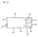
- FIG. 10 shows the bottom of connection module in greater detail.
- FIG. 11 is a perspective view of one of the front adapters held by a clip and connected to two connectors.
- FIG. 12 shows in greater detail a portion of the front of the connection module with the adapters and clips.
- FIG. 13 is a side view of a connection module like that shown in FIG. 9 , and showing an exemplary fiber from the first cable linked to a splice, an optical splitter, and two front adapters, one from each vertical row.
- FIG. 14 is a front view of the connection module of FIG. 13 .
- FIG. 15 is a side view of a connection module like that shown in FIG. 9 , and showing an exemplary fiber from the first cable linked to a splice, a WDM, and two front adapters, one from each vertical row.
- FIG. 16 is a front view of the connection module of FIG. 15 .
- FIG. 17 is a side view of a connection module like that shown in FIG. 9 , and showing an exemplary fiber from the first cable linked to a splice, and a front adapter.
- FIG. 18 shows an alternative connection module to the module of FIG. 8 with one vertical row of adapters.
- FIG. 19 shows a second alternative connection module with three vertical rows of adapters.
- FIG. 20 is a perspective view of a cross-connect storage module.
- FIG. 21 is a perspective view of an interconnect storage module.
- FIG. 22 is a perspective view of a two-position blank module.
- FIG. 23 is a one-position blank module.
- FIGS. 1 and 3 a fiber distribution apparatus 10 is shown for use in cross-connect applications.
- FIGS. 2 and 4 show a similar fiber distribution apparatus 10 ′ configured for interconnect applications.
- Both apparatus 10 , 10 ′ include an outer enclosure 20 , and an inner frame 22 including a plurality of optical modules 23 mounted thereto.
- modules 23 have particular functions, and apparatus 10 , 10 ′ is preferably provided with different modules 23 selected to have the desired functions for the particular application.
- Enclosure 20 typically extends from the ground over underground cables 300 , 302 ( FIG. 3 ) and 400 , 402 ( FIG. 4 ) which extend upwardly from the ground and contain multiple individual optical fibers or bundles of fibers. Cables 300 , 302 , 400 , 402 may be single cables or multiple cables. Enclosure 20 protects the inner components, in this case fiber optic telecommunications equipment. Enclosure 20 can be any convenient structure sized to protect frame 22 and modules 23 . In the drawings, enclosure 20 includes a main vertical portion 40 extending from the ground and a top cap 42 . Typically, a movable front door is provided, and a lock provides secure access.
- frame 22 is secured to main portion 40 of enclosure 20 along a rear side 41 of main portion 40 .
- Frame 22 includes a base or bottom 50 , and an opposed top 52 .
- Frame 22 further includes a front 54 , and an opposed rear 56 , and spaced apart sides 58 .
- Rear 56 of frame 22 can be screwed, riveted, or otherwise fastened to rear side 41 of main portion 40 of enclosure 20 through holes 62 .
- Frame 22 further includes an upper module mounting bracket 66 , and a lower module mounting bracket 68 extending between sides 58 .
- Each module mounting bracket 66 , 68 receives a plurality of modules 23 connected via fasteners 70 , such as screws, or other fasteners.
- the fasteners are releasable to enable removal of modules 23 , as desired, such as for repair, or replacement.
- Each of the module mounting brackets 66 , 68 includes a plurality of holes 67 , 69 for receipt of fasteners 70 .
- Lower module mounting bracket 68 defines a cable tray 60 ( FIG. 5 ) including a plurality of lower holes 72 , each sized for receipt of one or more cables, as will be described in greater detail below.
- a cover 76 ( FIGS. 5 and 6 ) mounts to frame 22 so as to close front 74 .
- Side flanges 78 to cover 76 include a plurality of downwardly angled slots 80 for receipt of pins 82 extending from sides 58 , 60 of frame 22 .
- Nuts, such as wing nuts, can be mounted to pins 82 with threads to help secure cover 76 to frame 22 .
- Connection module 24 comprises one of modules 23 .
- Connection module 24 includes a front 90 defining a plurality of connection locations 91 .
- Front 90 also includes opposed mounting flanges 92 , 94 extending along front 90 for mounting to module mounting brackets 66 , 68 of frame 22 .
- Each of flanges 92 , 94 includes a plurality of holes 96 , 98 for receiving fasteners 70 .
- a spaced apart rear 100 of connection module 24 , and a spaced apart top 102 and bottom 104 , and opposed, spaced apart sides 106 , 108 define an interior region.
- a cable notch 110 formed by portion of rear 100 , bottom 104 , and sides 106 , 108 receives a cable 300 for connection to the connection locations 91 within the interior of module 24 .
- Notch 110 further includes an opening 112 for cable 300 . Opening 112 is large enough to receive one or more additional cables.
- connection locations, 91 preferably includes an adapter 200 for mounting to a fiber optic connector, such as an SC (shown), an ST, an FC, or other connector.
- Cable 300 entering connector module 24 at opening 112 includes its individual fibers connected to the individual connection locations 91 , as desired.
- Two illustrated example fibers 300 a, 300 b of cable 300 connect to two connection locations 91 .
- a connector 208 ( FIG. 11 ) is preferably on an end of fibers 300 a, 300 b.
- Adapter 200 preferably has two ends 202 and 204 . End 202 is disposed within module 24 for connection to connector 208 . Opposite end 204 defines the exposed opening of the connection location 91 along the front of module 24 for connection to a second connector 218 .
- a clip 210 such as the clip disclosed in U.S. Pat. No. 5,214,735 may be used to releasably attach each adapter to module 24 .
- Clip 210 also angles connection locations 91 downwardly when module 24 is installed in frame 22 as in the drawings.
- Each clip 210 holds each adapter 200 in one of the openings 93 of front 90 of module 24 to define each connection location in the preferred embodiment. In the illustrated embodiment of module 24 , only two connection locations 91 are shown, but a fully loaded module 24 would define a connection location 91 at each opening 93 .
- Clip 210 is preferably a snap mounted clip to enable easy assembly.
- a removable clip 210 is preferred to allow cleaning of connector 208 and end 202 if desired.
- a similarly configured second connection module 24 a is mounted to frame 22 to permit cross-connection through the use of patch cords 114 a, 114 b ( FIG. 3 ) to cross-connect between the fibers of each cable connected to the respective connection modules 24 , 24 a.
- Cable 302 is connected to the rear of module 24 a as cable 300 is for module 24 .
- Patch cords 114 a, 114 b, and fibers 300 a, 300 b are shown schematically in FIGS. 3 and 9 , but each fiber has a connector like connectors 208 , 218 to mate with adapter 200 .
- other connector systems as noted above can be used, as desired.
- connection module 24 , 24 a can be made of sheet metal sections, held together with fasteners, such as screws, so as to allow access as desired to the interior of each module.
- a cross-connect storage module 26 as one of modules 23 having three spools 116 along a front 120 ( FIGS. 1 , 3 and 20 ).
- a front 120 of an interconnect storage module 26 a as one of modules 23 is provided two spools 116 ( FIGS. 2 , 4 and 21 ).
- Flanges 124 , 126 permit mounting of each storage module 26 , 26 a to frame 22 in a similar manner as modules 24 , 24 a.
- Holes 128 , 130 receive fasteners 70 to mount storage modules 26 , 26 a to frame 22 .
- Front projections 118 along vertical side edges 117 further enable cable management and cable protection during use.
- a cable clamp 134 ( FIG. 4 ) is provided for front mounting of one or more cables to storage module 26 a for the interconnect system.
- Posts 135 ( FIG. 21 ) hold the clamp pieces.
- Cable notch 110 is useful to avoid excess cable bending during manipulation and positioning of connection modules 24 .
- the use of notch 110 provides a greater distance between the cables extending upward from the ground to the clamp mounting locations on modules 24 . The extra distance is advantageous when manipulating module 24 as it is installed into or removed from frame 22 .
- two fibers 300 a, 300 b ( FIG. 9 ) of cable 300 are shown as optically linked to two fibers of cable 302 through patch cords 114 a, 114 b in a cross-connect application between modules 24 , 24 a.
- two fibers 402 a, 402 b of cable 400 are shown as optically linked to two fibers of cable 400 .
- connection modules 224 , 226 include different numbers of vertical rows of connector locations 91 .
- Modules 24 , 24 a included two vertical rows.
- Connection module 224 includes a single row of connection locations 91
- connection module 226 includes three. Four or more rows are also possible.
- module 24 is shown as including optical components such as splices and/or optical couplers within the module between cable 300 , and connection locations 91 .
- a splice 350 to a one-by-two optical splitter 351 allows for module 24 to have line and monitor functions associated with connection locations 91 .
- Row 352 of connection locations 91 could serve as the line function, and row 354 could serve as the monitor function.
- Each pair of connection locations 91 (one from each row) would be linked to one of the fibers of cable 300 in FIG. 13 .
- Other splitters, such as one-by-fours, etc. may be used, as desired.
- a splice 360 to a wave division multiplexer (WDM) 361 allows for module 24 to have wavelength division multiplexing functions associated with connection locations 91 .
- a “dense” wave division multiplexer may be used, if desired (DWDM).
- row 362 of connection locations 91 could serve as the first wavelength ports, and row 364 could serve as the different wavelength ports.
- Each pair of connection locations 91 (one from each row) would be linked to one of the fibers of cable 300 in FIG. 15 .
- FIG. 17 shows just a splicing component 370 so that each fiber of cable 300 could be spliced to a fiber leading to one connection location 91 .
- Other passive optical components can be selected as desired to provide module 24 with the desired function or functions.
- Blank panels 150 , 170 comprising modules 23 are shown.
- Each blank panel 150 , 170 includes a generally planar front 152 , and flanges 154 including holes 158 , 160 to enable mounting of the blank modules 150 , 170 to frame 22 .
- Blank modules 150 , 170 are utilized to fill open spaces of frame 22 .
- Blank module 170 is a single width, and blank module 150 is a double width. Additional widths can be supplied as desired.
- the desired function cross-connect, interconnect, other
- the types of modules 23 connection, storage, blank
- widths of modules 23 are also selected. Further the types of connections and whether any optical splices or optical couplers are to be utilized are selected.
- the appropriate modules are selected and then mounted to frame 22 within an enclosure 20 . Over time, the modules 23 can be removed for repair, replacement, or to change function. Also, the front connections can be changed as the need arises.
Abstract
Description
Claims (39)
Priority Applications (1)
| Application Number | Priority Date | Filing Date | Title |
|---|---|---|---|
| US10/810,547 USRE40358E1 (en) | 1998-07-27 | 2004-03-26 | Outside plant fiber distribution apparatus and method |
Applications Claiming Priority (3)
| Application Number | Priority Date | Filing Date | Title |
|---|---|---|---|
| US09/122,947 US6160946A (en) | 1998-07-27 | 1998-07-27 | Outside plant fiber distribution apparatus and method |
| US09/689,989 US6363200B1 (en) | 1998-07-27 | 2000-10-13 | Outside plant fiber distribution apparatus and method |
| US10/810,547 USRE40358E1 (en) | 1998-07-27 | 2004-03-26 | Outside plant fiber distribution apparatus and method |
Related Parent Applications (1)
| Application Number | Title | Priority Date | Filing Date |
|---|---|---|---|
| US09/689,989 Reissue US6363200B1 (en) | 1998-07-27 | 2000-10-13 | Outside plant fiber distribution apparatus and method |
Publications (1)
| Publication Number | Publication Date |
|---|---|
| USRE40358E1 true USRE40358E1 (en) | 2008-06-03 |
Family
ID=22405832
Family Applications (5)
| Application Number | Title | Priority Date | Filing Date |
|---|---|---|---|
| US09/122,947 Expired - Lifetime US6160946A (en) | 1998-07-27 | 1998-07-27 | Outside plant fiber distribution apparatus and method |
| US09/689,989 Ceased US6363200B1 (en) | 1998-07-27 | 2000-10-13 | Outside plant fiber distribution apparatus and method |
| US10/810,547 Expired - Lifetime USRE40358E1 (en) | 1998-07-27 | 2004-03-26 | Outside plant fiber distribution apparatus and method |
| US12/218,240 Expired - Lifetime USRE42258E1 (en) | 1998-07-27 | 2008-07-11 | Outside plant fiber distribution apparatus and method |
| US12/218,241 Expired - Lifetime USRE41777E1 (en) | 1998-07-27 | 2008-07-11 | Outside plant fiber distribution apparatus and method |
Family Applications Before (2)
| Application Number | Title | Priority Date | Filing Date |
|---|---|---|---|
| US09/122,947 Expired - Lifetime US6160946A (en) | 1998-07-27 | 1998-07-27 | Outside plant fiber distribution apparatus and method |
| US09/689,989 Ceased US6363200B1 (en) | 1998-07-27 | 2000-10-13 | Outside plant fiber distribution apparatus and method |
Family Applications After (2)
| Application Number | Title | Priority Date | Filing Date |
|---|---|---|---|
| US12/218,240 Expired - Lifetime USRE42258E1 (en) | 1998-07-27 | 2008-07-11 | Outside plant fiber distribution apparatus and method |
| US12/218,241 Expired - Lifetime USRE41777E1 (en) | 1998-07-27 | 2008-07-11 | Outside plant fiber distribution apparatus and method |
Country Status (7)
| Country | Link |
|---|---|
| US (5) | US6160946A (en) |
| EP (1) | EP1101138A2 (en) |
| CN (1) | CN1354839A (en) |
| AU (1) | AU1308000A (en) |
| BR (1) | BR9912463A (en) |
| CA (1) | CA2338449A1 (en) |
| WO (1) | WO2000007053A2 (en) |
Cited By (19)
| Publication number | Priority date | Publication date | Assignee | Title |
|---|---|---|---|---|
| US7653282B2 (en) | 2004-01-27 | 2010-01-26 | Corning Cable Systems Llc | Multi-port optical connection terminal |
| USRE41777E1 (en) | 1998-07-27 | 2010-09-28 | Adc Telecommunications, Inc. | Outside plant fiber distribution apparatus and method |
| US7805044B2 (en) | 2004-11-03 | 2010-09-28 | Adc Telecommunications, Inc. | Fiber drop terminal |
| US20110097052A1 (en) * | 2009-10-21 | 2011-04-28 | Solheid James J | Fiber Access Terminal Mounted at a Mid-Span Access Location of a Telecommunications Cable |
| US20160276817A1 (en) * | 2015-03-16 | 2016-09-22 | Commscope Technologies Llc | Enclosure for cable distribution assembly |
| US9977211B1 (en) | 2017-04-21 | 2018-05-22 | Afl Telecommunications Llc | Optical connection terminals for fiber optic communications networks |
| USD825471S1 (en) | 2016-03-16 | 2018-08-14 | Commscope Technologies Llc | Cable breakout enclosure design |
| US10164389B2 (en) | 2016-09-26 | 2018-12-25 | Commscope Technologies Llc | Breakout enclosure for transitioning from trunk cable to jumper cable |
| US10209475B2 (en) | 2017-03-21 | 2019-02-19 | Commscope Technologies Llc | Modular breakout enclosure for transitioning from trunk cable to jumper cable |
| US10234634B2 (en) | 2016-01-07 | 2019-03-19 | Commscope Technologies Llc | Flexible device for distributing hybrid cable and transitioning from trunk cable to jumper cable |
| US10281670B2 (en) | 2015-01-12 | 2019-05-07 | Afl Telecommunications Llc | Fiber optic terminal enclosure |
| US10355423B2 (en) | 2016-10-24 | 2019-07-16 | Commscope Technologies Llc | Hybrid connector assembly with integrated overvoltage protection |
| US10502915B2 (en) | 2017-06-29 | 2019-12-10 | Commscope Technologies Llc | Device for distributing trunk cable to jumper cable |
| US10520692B2 (en) | 2015-11-11 | 2019-12-31 | Afl Telecommunications Llc | Optical connection terminals for fiber optic communications networks |
| USD876364S1 (en) | 2016-03-16 | 2020-02-25 | Commscope Technologies Llc | Cable breakout enclosure |
| US11002931B2 (en) * | 2014-09-16 | 2021-05-11 | CommScope Connectivity Belgium BVBA | Telecommunications tray with a cable routing path extending through a pivot hinge |
| US11002932B2 (en) | 2014-09-16 | 2021-05-11 | CommScope Connectivity Belgium BVBA | Multi-positionable telecommunications tray |
| US11036019B2 (en) | 2014-09-16 | 2021-06-15 | CommScope Connectivity Belgium BVBA | Telecommunications tray assembly |
| US11175469B2 (en) | 2017-10-26 | 2021-11-16 | CommScope Connectivity Belgium BVBA | Telecommunications system |
Families Citing this family (159)
| Publication number | Priority date | Publication date | Assignee | Title |
|---|---|---|---|---|
| US6721482B1 (en) | 1998-09-10 | 2004-04-13 | Thomas A. Glynn | Telecommunications fiber optic infrastructure |
| US6522737B1 (en) * | 1999-02-10 | 2003-02-18 | Avaya Technology Corp. | System and method of operation for a telecommunications patch system |
| US6760531B1 (en) | 1999-03-01 | 2004-07-06 | Adc Telecommunications, Inc. | Optical fiber distribution frame with outside plant enclosure |
| US6556763B1 (en) * | 1999-03-01 | 2003-04-29 | Adc Telecommunications, Inc. | Optical fiber distribution frame with connector modules |
| US6382845B1 (en) * | 1999-03-02 | 2002-05-07 | Ameritech Corporation | Fiber optic patch kit and method for using same |
| EP1183808A1 (en) | 1999-05-24 | 2002-03-06 | Marconi Intellectual Property (Ringfence) Inc. | Apparatus and methods for maintaining balanced communication channels with increasing service demands |
| US6496641B1 (en) * | 1999-08-12 | 2002-12-17 | Bellsouth Intellectual Property Corporation | Fiber optic interface device |
| CN1398232A (en) * | 2000-02-07 | 2003-02-19 | 特赫鲁赫鲁器材有限公司 | Portable-pente ski tow |
| US6301424B1 (en) * | 2000-04-13 | 2001-10-09 | Lucent Technologies Inc. | Distribution frame cable routing apparatus |
| JP4087046B2 (en) * | 2000-09-06 | 2008-05-14 | ヒロセ電機株式会社 | Optical cable adapter or connector and its mounting member |
| US6572272B2 (en) * | 2000-11-29 | 2003-06-03 | Berg Technology, Inc. | Angled optical connector mounting assembly |
| US6487358B1 (en) * | 2001-07-27 | 2002-11-26 | Ciena Corporation | Blank module with conduit retainer |
| JP3921063B2 (en) * | 2001-09-17 | 2007-05-30 | ヒロセ電機株式会社 | Optical connector shield structure |
| US7029182B2 (en) * | 2002-03-01 | 2006-04-18 | Fci Americas Technology, Inc. | Angled optical connector adapter mounting assembly |
| US6586673B1 (en) * | 2002-05-24 | 2003-07-01 | Hernan F. Socarras | Service loop tray and assembly for low voltage cables |
| US6950592B1 (en) * | 2002-05-31 | 2005-09-27 | Ciena Corporation | Fiber optic cable management system |
| US6766094B2 (en) * | 2002-06-28 | 2004-07-20 | Corning Cable Systems Llc | Aerial closure for local convergence point |
| DE10307944B4 (en) * | 2003-02-25 | 2005-08-18 | Berthold Sichert Gmbh | Retractable distribution cabinet |
| US7142764B2 (en) | 2003-03-20 | 2006-11-28 | Tyco Electronics Corporation | Optical fiber interconnect cabinets, termination modules and fiber connectivity management for the same |
| US6870734B2 (en) * | 2003-05-30 | 2005-03-22 | Adc Telecommunications, Inc. | Fiber containment system |
| US7198409B2 (en) | 2003-06-30 | 2007-04-03 | Adc Telecommunications, Inc. | Fiber optic connector holder and method |
| US7233731B2 (en) | 2003-07-02 | 2007-06-19 | Adc Telecommunications, Inc. | Telecommunications connection cabinet |
| US6983095B2 (en) * | 2003-11-17 | 2006-01-03 | Fiber Optic Network Solutions Corporation | Systems and methods for managing optical fibers and components within an enclosure in an optical communications network |
| US7369741B2 (en) | 2003-11-17 | 2008-05-06 | Fiber Optics Network Solutions Corp. | Storage adapter with dust cap posts |
| EP1730564B1 (en) | 2004-03-08 | 2009-11-11 | ADC Telecommunications, Inc. | Fiber access terminal |
| US7218827B2 (en) | 2004-06-18 | 2007-05-15 | Adc Telecommunications, Inc. | Multi-position fiber optic connector holder and method |
| US7680388B2 (en) * | 2004-11-03 | 2010-03-16 | Adc Telecommunications, Inc. | Methods for configuring and testing fiber drop terminals |
| US7079745B1 (en) * | 2005-02-14 | 2006-07-18 | Sbc Knowledge Ventures, L.P. | Spool assembly for absorbing slack of fiber optic jumpers routed through raceways and network equipment |
| DE102005011208A1 (en) * | 2005-03-09 | 2006-09-21 | Adc Gmbh | Fiber optic cable termination |
| US7194181B2 (en) * | 2005-03-31 | 2007-03-20 | Adc Telecommunications, Inc. | Adapter block including connector storage |
| WO2006135524A2 (en) * | 2005-05-18 | 2006-12-21 | Corning Cable Systems Llc | High density optical fiber distribution enclosure |
| US7623749B2 (en) | 2005-08-30 | 2009-11-24 | Adc Telecommunications, Inc. | Fiber distribution hub with modular termination blocks |
| US7418181B2 (en) * | 2006-02-13 | 2008-08-26 | Adc Telecommunications, Inc. | Fiber optic splitter module |
| US7816602B2 (en) | 2006-02-13 | 2010-10-19 | Adc Telecommunications, Inc. | Fiber distribution hub with outside accessible grounding terminals |
| US7720343B2 (en) | 2006-02-13 | 2010-05-18 | Adc Telecommunications, Inc. | Fiber distribution hub with swing frame and modular termination panels |
| US7760984B2 (en) | 2006-05-04 | 2010-07-20 | Adc Telecommunications, Inc. | Fiber distribution hub with swing frame and wrap-around doors |
| US20080069513A1 (en) * | 2006-09-15 | 2008-03-20 | Desanti Raymond J | Fiber optic cable entry device |
| US7711234B2 (en) | 2006-10-02 | 2010-05-04 | Adc Telecommunications, Inc. | Reskinnable fiber distribution hub |
| US7496268B2 (en) | 2006-12-13 | 2009-02-24 | Corning Cable Systems Llc | High density fiber optic hardware |
| US7349616B1 (en) | 2007-01-12 | 2008-03-25 | Corning Cable Systems Llc | Fiber optic local convergence points for multiple dwelling units |
| US7822310B2 (en) | 2007-02-28 | 2010-10-26 | Corning Cable Systems Llc | Fiber optic splice trays |
| US7558458B2 (en) * | 2007-03-08 | 2009-07-07 | Adc Telecommunications, Inc. | Universal bracket for mounting a drop terminal |
| US7522805B2 (en) * | 2007-03-09 | 2009-04-21 | Adc Telecommunications, Inc. | Wall mount distribution arrangement |
| US7512304B2 (en) | 2007-03-23 | 2009-03-31 | Adc Telecommunications, Inc. | Drop terminal with anchor block for retaining a stub cable |
| US20090046985A1 (en) * | 2007-08-16 | 2009-02-19 | Erik Gronvall | Fiber Optic Enclosure Internal Cable Management |
| US8798427B2 (en) | 2007-09-05 | 2014-08-05 | Corning Cable Systems Llc | Fiber optic terminal assembly |
| US7740409B2 (en) | 2007-09-19 | 2010-06-22 | Corning Cable Systems Llc | Multi-port optical connection terminal |
| US7903923B2 (en) | 2007-10-09 | 2011-03-08 | Adc Telecommunications, Inc. | Drop terminal releasable engagement mechanism |
| AU2008310798B2 (en) | 2007-10-09 | 2013-11-21 | Adc Telecommunications, Inc. | Mini drop terminal |
| US7751672B2 (en) | 2007-10-31 | 2010-07-06 | Adc Telecommunications, Inc. | Low profile fiber distribution hub |
| US7406242B1 (en) | 2007-11-16 | 2008-07-29 | Tyco Electronics Co., Ltd. | Interconnect enclosures for optical fibers including cross-connect modules and methods for using the same |
| US8229265B2 (en) | 2007-11-21 | 2012-07-24 | Adc Telecommunications, Inc. | Fiber distribution hub with multiple configurations |
| US8238709B2 (en) | 2007-12-18 | 2012-08-07 | Adc Telecommunications, Inc. | Multi-configuration mounting system for fiber distribution hub |
| US20090196563A1 (en) * | 2008-02-01 | 2009-08-06 | Mullsteff David M | Multi-Fiber Optical Patch Cord Breakout Assembly |
| US7715682B2 (en) * | 2008-03-04 | 2010-05-11 | Adc Telecommunications, Inc. | Fiber distribution hub having an adjustable plate |
| US7889961B2 (en) | 2008-03-27 | 2011-02-15 | Corning Cable Systems Llc | Compact, high-density adapter module, housing assembly and frame assembly for optical fiber telecommunications |
| CA2725393A1 (en) * | 2008-04-11 | 2009-10-15 | Adc Telecommunications, Inc. | Fiber management panel |
| GB0812268D0 (en) * | 2008-07-04 | 2008-08-13 | Tyco Electronics Raychem Nv | Improvements in or relating to optical fibre distribution systems |
| ES2560802T3 (en) | 2008-08-27 | 2016-02-22 | Adc Telecommunications, Inc. | Fiber optic adapter with integrally molded bushing alignment structure |
| US11294135B2 (en) | 2008-08-29 | 2022-04-05 | Corning Optical Communications LLC | High density and bandwidth fiber optic apparatuses and related equipment and methods |
| US8452148B2 (en) | 2008-08-29 | 2013-05-28 | Corning Cable Systems Llc | Independently translatable modules and fiber optic equipment trays in fiber optic equipment |
| CN102209921B (en) | 2008-10-09 | 2015-11-25 | 康宁光缆系统有限公司 | There is the fibre-optic terminus supported from the adapter panel of the input and output optical fiber of optical splitters |
| US7933285B2 (en) * | 2008-10-24 | 2011-04-26 | At&T Intellectual Property I, L.P. | Distributed digital subscriber line access multiplexers to increase bandwidth in access networks |
| US8879882B2 (en) | 2008-10-27 | 2014-11-04 | Corning Cable Systems Llc | Variably configurable and modular local convergence point |
| US8224144B2 (en) | 2008-10-31 | 2012-07-17 | Tyco Electronics Corporation | Fiber optic connector storage apparatus and methods for using the same |
| US8275262B2 (en) | 2008-11-10 | 2012-09-25 | At&T Intellectual Property I, L.P. | Methods and apparatus to deploy fiber optic based access networks |
| MX2011005380A (en) | 2008-11-21 | 2011-06-06 | Adc Telecommunications Inc | Fiber optic telecommunications module. |
| ATE534049T1 (en) | 2009-02-24 | 2011-12-15 | Ccs Technology Inc | CABLE HOLDING DEVICE OR ARRANGEMENT FOR USE WITH A CABLE |
| EP2237091A1 (en) | 2009-03-31 | 2010-10-06 | Corning Cable Systems LLC | Removably mountable fiber optic terminal |
| US8699838B2 (en) | 2009-05-14 | 2014-04-15 | Ccs Technology, Inc. | Fiber optic furcation module |
| US8280216B2 (en) | 2009-05-21 | 2012-10-02 | Corning Cable Systems Llc | Fiber optic equipment supporting moveable fiber optic equipment tray(s) and module(s), and related equipment and methods |
| US9075216B2 (en) | 2009-05-21 | 2015-07-07 | Corning Cable Systems Llc | Fiber optic housings configured to accommodate fiber optic modules/cassettes and fiber optic panels, and related components and methods |
| AU2010263057A1 (en) | 2009-06-19 | 2012-02-02 | Corning Cable Systems Llc | High density and bandwidth fiber optic apparatuses and related equipment and methods |
| US8433171B2 (en) | 2009-06-19 | 2013-04-30 | Corning Cable Systems Llc | High fiber optic cable packing density apparatus |
| US8712206B2 (en) | 2009-06-19 | 2014-04-29 | Corning Cable Systems Llc | High-density fiber optic modules and module housings and related equipment |
| ES2403007A1 (en) * | 2009-07-01 | 2013-05-13 | Adc Telecommunications, Inc | Wall-mounted fiber distribution hub |
| US20110026930A1 (en) | 2009-07-29 | 2011-02-03 | Zhi Cui | Methods and apparatus to upgrade communication services in subscriber distribution areas |
| US8467651B2 (en) | 2009-09-30 | 2013-06-18 | Ccs Technology Inc. | Fiber optic terminals configured to dispose a fiber optic connection panel(s) within an optical fiber perimeter and related methods |
| US8625950B2 (en) | 2009-12-18 | 2014-01-07 | Corning Cable Systems Llc | Rotary locking apparatus for fiber optic equipment trays and related methods |
| US8593828B2 (en) | 2010-02-04 | 2013-11-26 | Corning Cable Systems Llc | Communications equipment housings, assemblies, and related alignment features and methods |
| EP2542930A1 (en) | 2010-03-02 | 2013-01-09 | Tyco Electronics Services GmbH | Fibre-optic telecommunication module |
| US8649649B2 (en) | 2010-03-03 | 2014-02-11 | Adc Telecommunications, Inc. | Fiber distribution hub with connectorized stub cables |
| US9547144B2 (en) | 2010-03-16 | 2017-01-17 | Corning Optical Communications LLC | Fiber optic distribution network for multiple dwelling units |
| US20110235986A1 (en) * | 2010-03-24 | 2011-09-29 | Adc Telecommunications, Inc. | Optical fiber drawer with connectorized stub cable |
| US8913866B2 (en) | 2010-03-26 | 2014-12-16 | Corning Cable Systems Llc | Movable adapter panel |
| AU2011265751B2 (en) | 2010-04-16 | 2015-09-10 | Corning Optical Communications LLC | Sealing and strain relief device for data cables |
| US8792767B2 (en) | 2010-04-16 | 2014-07-29 | Ccs Technology, Inc. | Distribution device |
| EP2381284B1 (en) | 2010-04-23 | 2014-12-31 | CCS Technology Inc. | Under floor fiber optic distribution device |
| US8879881B2 (en) | 2010-04-30 | 2014-11-04 | Corning Cable Systems Llc | Rotatable routing guide and assembly |
| US8660397B2 (en) | 2010-04-30 | 2014-02-25 | Corning Cable Systems Llc | Multi-layer module |
| US9720195B2 (en) | 2010-04-30 | 2017-08-01 | Corning Optical Communications LLC | Apparatuses and related components and methods for attachment and release of fiber optic housings to and from an equipment rack |
| US9632270B2 (en) | 2010-04-30 | 2017-04-25 | Corning Optical Communications LLC | Fiber optic housings configured for tool-less assembly, and related components and methods |
| US9075217B2 (en) | 2010-04-30 | 2015-07-07 | Corning Cable Systems Llc | Apparatuses and related components and methods for expanding capacity of fiber optic housings |
| US8705926B2 (en) | 2010-04-30 | 2014-04-22 | Corning Optical Communications LLC | Fiber optic housings having a removable top, and related components and methods |
| US9519118B2 (en) | 2010-04-30 | 2016-12-13 | Corning Optical Communications LLC | Removable fiber management sections for fiber optic housings, and related components and methods |
| US8891927B2 (en) | 2010-05-07 | 2014-11-18 | Adc Telecommunications, Inc. | Fiber distribution hub with pass-through interfaces |
| CN101923197A (en) * | 2010-08-04 | 2010-12-22 | 南京华脉科技有限公司 | Main distribution frame for fiber |
| US8718436B2 (en) | 2010-08-30 | 2014-05-06 | Corning Cable Systems Llc | Methods, apparatuses for providing secure fiber optic connections |
| US9547145B2 (en) | 2010-10-19 | 2017-01-17 | Corning Optical Communications LLC | Local convergence point for multiple dwelling unit fiber optic distribution network |
| US9279951B2 (en) | 2010-10-27 | 2016-03-08 | Corning Cable Systems Llc | Fiber optic module for limited space applications having a partially sealed module sub-assembly |
| EP2633354A1 (en) | 2010-10-28 | 2013-09-04 | Corning Cable Systems LLC | Impact resistant fiber optic enclosures and related methods |
| US9116324B2 (en) | 2010-10-29 | 2015-08-25 | Corning Cable Systems Llc | Stacked fiber optic modules and fiber optic equipment configured to support stacked fiber optic modules |
| US8662760B2 (en) | 2010-10-29 | 2014-03-04 | Corning Cable Systems Llc | Fiber optic connector employing optical fiber guide member |
| CA2819235C (en) | 2010-11-30 | 2018-01-16 | Corning Cable Systems Llc | Fiber device holder and strain relief device |
| EP2671107A1 (en) | 2011-02-02 | 2013-12-11 | Corning Cable Systems LLC | Dense shuttered fiber optic connectors and assemblies suitable for establishing optical connections for optical backplanes in equipment racks |
| MX2012014755A (en) * | 2011-03-28 | 2013-01-29 | Afl Telecommunications Llc | Exterior distribution pedestal cabinet. |
| US9008485B2 (en) | 2011-05-09 | 2015-04-14 | Corning Cable Systems Llc | Attachment mechanisms employed to attach a rear housing section to a fiber optic housing, and related assemblies and methods |
| US9223106B2 (en) | 2011-06-24 | 2015-12-29 | Commscope Technologies Llc | Fiber termination enclosure with modular plate assemblies |
| CN103649805B (en) | 2011-06-30 | 2017-03-15 | 康宁光电通信有限责任公司 | Fiber plant assembly of shell using non-U-width size and associated method |
| US9081164B2 (en) | 2011-08-24 | 2015-07-14 | Adc Telecommunications, Inc. | Fiber management panel |
| US8953924B2 (en) | 2011-09-02 | 2015-02-10 | Corning Cable Systems Llc | Removable strain relief brackets for securing fiber optic cables and/or optical fibers to fiber optic equipment, and related assemblies and methods |
| US9417418B2 (en) | 2011-09-12 | 2016-08-16 | Commscope Technologies Llc | Flexible lensed optical interconnect device for signal distribution |
| CN104041066A (en) | 2011-10-03 | 2014-09-10 | 蒂科电子瑞侃有限公司 | Aggregation enclosure for elevated, outdoor locations |
| EP2764390B1 (en) | 2011-10-07 | 2020-12-02 | CommScope Technologies LLC | Fiber optic cassette, system, and method |
| US9069151B2 (en) | 2011-10-26 | 2015-06-30 | Corning Cable Systems Llc | Composite cable breakout assembly |
| US9038832B2 (en) | 2011-11-30 | 2015-05-26 | Corning Cable Systems Llc | Adapter panel support assembly |
| US9219546B2 (en) | 2011-12-12 | 2015-12-22 | Corning Optical Communications LLC | Extremely high frequency (EHF) distributed antenna systems, and related components and methods |
| US10110307B2 (en) | 2012-03-02 | 2018-10-23 | Corning Optical Communications LLC | Optical network units (ONUs) for high bandwidth connectivity, and related components and methods |
| US9020321B2 (en) | 2012-04-10 | 2015-04-28 | Tyco Electronics Corporation | Wall outlet having enclosed service connection |
| US8873926B2 (en) | 2012-04-26 | 2014-10-28 | Corning Cable Systems Llc | Fiber optic enclosures employing clamping assemblies for strain relief of cables, and related assemblies and methods |
| US9004778B2 (en) | 2012-06-29 | 2015-04-14 | Corning Cable Systems Llc | Indexable optical fiber connectors and optical fiber connector arrays |
| US9250409B2 (en) | 2012-07-02 | 2016-02-02 | Corning Cable Systems Llc | Fiber-optic-module trays and drawers for fiber-optic equipment |
| US9049500B2 (en) | 2012-08-31 | 2015-06-02 | Corning Cable Systems Llc | Fiber optic terminals, systems, and methods for network service management |
| US9042702B2 (en) | 2012-09-18 | 2015-05-26 | Corning Cable Systems Llc | Platforms and systems for fiber optic cable attachment |
| US9146362B2 (en) | 2012-09-21 | 2015-09-29 | Adc Telecommunications, Inc. | Insertion and removal tool for a fiber optic ferrule alignment sleeve |
| US9146374B2 (en) | 2012-09-28 | 2015-09-29 | Adc Telecommunications, Inc. | Rapid deployment packaging for optical fiber |
| ES2792122T3 (en) | 2012-09-28 | 2020-11-10 | Commscope Connectivity Uk Ltd | Fiber optic cassette |
| US9223094B2 (en) | 2012-10-05 | 2015-12-29 | Tyco Electronics Nederland Bv | Flexible optical circuit, cassettes, and methods |
| US8909019B2 (en) | 2012-10-11 | 2014-12-09 | Ccs Technology, Inc. | System comprising a plurality of distribution devices and distribution device |
| EP2725397B1 (en) | 2012-10-26 | 2015-07-29 | CCS Technology, Inc. | Fiber optic management unit and fiber optic distribution device |
| US9140871B2 (en) * | 2012-12-11 | 2015-09-22 | Christie Digital Systems Usa, Inc. | Optical fiber carrier |
| EP2936228A1 (en) * | 2012-12-19 | 2015-10-28 | Tyco Electronics Raychem BVBA | Distribution device with incrementally added splitters |
| US8985862B2 (en) | 2013-02-28 | 2015-03-24 | Corning Cable Systems Llc | High-density multi-fiber adapter housings |
| US9435975B2 (en) | 2013-03-15 | 2016-09-06 | Commscope Technologies Llc | Modular high density telecommunications frame and chassis system |
| WO2014147059A2 (en) | 2013-03-19 | 2014-09-25 | Adc Czech Republic, S.R.O. | Moveable bend control and patch cord support for telecommunications panels |
| US9584879B2 (en) | 2013-05-29 | 2017-02-28 | Go!Foton Holdings, Inc. | Patch panel cable retention mechanisms |
| US9472934B2 (en) | 2013-06-24 | 2016-10-18 | Paige Electric Company, Lp | Enclosure for electrical equipment |
| CN106133572B (en) | 2014-01-28 | 2018-11-09 | Adc电信公司 | Slidably optical link module with cable slack management |
| USD837151S1 (en) * | 2014-02-07 | 2019-01-01 | Tdk-Lambda Limited | Rectifier for power supply |
| US9494758B2 (en) | 2014-04-03 | 2016-11-15 | Commscope Technologies Llc | Fiber optic distribution system |
| US9632271B2 (en) * | 2014-06-17 | 2017-04-25 | Ortronics, Inc. | Modularly mountable cable management systems and associated methods |
| AU2015276109B2 (en) | 2014-06-17 | 2020-11-19 | Adc Czech Republic, S.R.O. | Cable distribution system |
| US10976512B2 (en) | 2014-09-23 | 2021-04-13 | Ppc Broadband, Inc. | House box with mounting surface for mounted access |
| US9882362B2 (en) | 2014-09-23 | 2018-01-30 | Ppc Broadband, Inc. | Enclosure for controling access to different telecommunication components |
| US9952397B2 (en) | 2014-09-23 | 2018-04-24 | Ppc Broadband Inc. | Universal multi-purpose compartmentalized telecommunications box |
| US10509187B2 (en) | 2014-09-23 | 2019-12-17 | Ppc Broadband, Inc. | Universal multi-purpose compartmentalized telecommunications box |
| WO2016170173A1 (en) | 2015-04-23 | 2016-10-27 | CommScope Connectivity Belgium BVBA | Telecommunications panel assembly with movable adapters |
| EP3296785A4 (en) | 2015-05-15 | 2019-05-29 | ADC Telecommunications (Shanghai) Distribution Co., Ltd. | Alignment sleeve assembly and optical fibre adapter |
| US9851523B2 (en) | 2015-09-22 | 2017-12-26 | Go!Foton Holdings, Inc. | Apparatus for cable routing |
| US10606009B2 (en) | 2015-12-01 | 2020-03-31 | CommScope Connectivity Belgium BVBA | Cable distribution system with fan out devices |
| US10637220B2 (en) | 2016-01-28 | 2020-04-28 | CommScope Connectivity Belgium BVBA | Modular hybrid closure |
| US10788641B2 (en) | 2016-02-12 | 2020-09-29 | Ppc Broadband, Inc. | Cable spool and storage |
| US10606006B2 (en) | 2016-09-20 | 2020-03-31 | Clearfield, Inc. | Optical fiber distribution systems and components |
| US10859781B2 (en) | 2016-09-20 | 2020-12-08 | Clearfield, Inc. | Optical fiber distribution systems and components |
| US10291969B2 (en) | 2017-02-14 | 2019-05-14 | Go!Foton Holdings, Inc. | Rear cable management |
| US10310206B2 (en) | 2017-05-22 | 2019-06-04 | Go!Foton Holdings, Inc. | Apparatus for cable routing |
| US10656358B2 (en) * | 2017-07-25 | 2020-05-19 | Ofs Fitel, Llc | Fiber optic network distribution module for use along an outdoor multi-fiber network distribution cable |
| WO2019070682A2 (en) | 2017-10-02 | 2019-04-11 | Commscope Technologies Llc | Fiber optic circuit and preparation method |
| US11163128B2 (en) | 2019-03-20 | 2021-11-02 | Ppc Broadband, Inc. | Enclosure for spliced cables for use in an outdoor environment |
Citations (68)
| Publication number | Priority date | Publication date | Assignee | Title |
|---|---|---|---|---|
| US4652072A (en) * | 1986-04-28 | 1987-03-24 | Wire Tech Incorporated | Cable-connector assembly |
| US4717231A (en) | 1983-01-05 | 1988-01-05 | Vincent Dewez | Interconnecting and distributing box for optical fibers |
| US4805979A (en) | 1987-09-04 | 1989-02-21 | Minnesota Mining And Manufacturing Company | Fiber optic cable splice closure |
| US4986762A (en) | 1989-08-15 | 1991-01-22 | Minnesota Mining And Manufacturing Company | Termination module for use in an array of modules |
| US5029958A (en) | 1989-04-28 | 1991-07-09 | Scientific-Atlanta, Inc. | Optical fiber enclosure for optoelectronic converter |
| US5046811A (en) | 1989-07-17 | 1991-09-10 | Jung Roger E | Junction box for optical communications cords, and gland assembly for cord |
| US5097529A (en) | 1991-03-22 | 1992-03-17 | At&T Bell Laboratories | Space-saving optical fiber cable closure |
| US5122069A (en) | 1989-07-28 | 1992-06-16 | Amp Incorporated | Access flooring module |
| US5129030A (en) | 1991-05-30 | 1992-07-07 | At&T Bell Laboratories | Movable lightguide connector panel |
| US5133038A (en) | 1980-04-17 | 1992-07-21 | Reliance Comm/Tec. Corporation | Fiber optic splice case |
| EP0511147A1 (en) | 1991-04-22 | 1992-10-28 | Telefonica De Espana, S.A. | Universal access optical fiber junction box |
| US5212761A (en) * | 1992-04-27 | 1993-05-18 | At&T Bell Laboratories | Fiber optic module |
| US5214735A (en) | 1992-04-06 | 1993-05-25 | Adc Telecommunications, Inc. | Fiber optic connector retainer |
| US5231687A (en) | 1990-06-04 | 1993-07-27 | Bicc Plc | Termination system for optical fibres |
| US5235665A (en) | 1991-05-06 | 1993-08-10 | Sirti S.P.A. | Branching device for fibre-optic cables |
| US5267122A (en) | 1992-06-15 | 1993-11-30 | Alcatel Network Systems, Inc. | Optical network unit |
| US5363465A (en) | 1993-02-19 | 1994-11-08 | Adc Telecommunications, Inc. | Fiber optic connector module |
| US5367598A (en) | 1993-10-21 | 1994-11-22 | Nec America, Inc. | Interface chassis for fiber optic transport system |
| WO1995007478A1 (en) | 1993-09-10 | 1995-03-16 | British Telecommunications Public Limited Company | Break-out tray |
| USRE34955E (en) | 1989-07-31 | 1995-05-30 | Adc Telecommunications, Inc. | Optical fiber distribution frame |
| US5446823A (en) | 1994-01-26 | 1995-08-29 | Raychem Corporation | Aerial, pedestal, below grade, or buried optical fiber closure |
| US5509099A (en) | 1995-04-26 | 1996-04-16 | Antec Corp. | Optical fiber closure with sealed cable entry ports |
| JPH0915426A (en) | 1995-06-26 | 1997-01-17 | Nippon Chemitec Kk | Light guiding plate and surface type lighting body using the light guiding plate |
| US5633973A (en) | 1994-12-08 | 1997-05-27 | Alcatel Cable Interface | Splice box for splicing together opticl-fiber cables |
| US5659650A (en) | 1995-09-26 | 1997-08-19 | Lucent Technologies Inc. | Hinged faceplate |
| EP0805536A1 (en) | 1996-05-01 | 1997-11-05 | Bowthorpe Plc | Cable enclosure |
| US5689607A (en) | 1994-12-08 | 1997-11-18 | Alcatel Cable Interface | Device for holding at least one optical fiber cable, and a splice box making use of the device |
| US5701380A (en) | 1996-06-24 | 1997-12-23 | Telect, Inc. | Fiber optic module for high density supply of patching and splicing |
| US5732180A (en) | 1995-06-09 | 1998-03-24 | Multilink, Inc. | Method and apparatus for sealing fiber optic entryways to a sealed enclosure |
| US5734776A (en) | 1996-08-28 | 1998-03-31 | Adc Telecommunications, Inc. | Outside plant cross-connect apparatus |
| US5745633A (en) | 1996-12-24 | 1998-04-28 | Siecor Corporation | Fiber optic cable assembly for securing a fiber optic cable within an input port of a splice closure |
| US5758003A (en) | 1996-03-15 | 1998-05-26 | Adc Telecommunications, Inc. | High density fiber management |
| EP0844504A2 (en) | 1996-11-21 | 1998-05-27 | RXS Kabelgarnituren Gesellschaft mit beschränkter Haftung | Connection box for optical cables |
| EP0851257A1 (en) | 1996-12-31 | 1998-07-01 | Siecor Corporation | Optical fiber connector housing |
| US5781678A (en) | 1995-01-25 | 1998-07-14 | Sumitomo Electric Industries, Ltd. | Optical fiber path joint member and method of blowing optical fiber |
| US5828807A (en) | 1996-04-30 | 1998-10-27 | Next Level Communications | Optical network unit (ONU) mechanical enclosure |
| US5892870A (en) | 1995-11-16 | 1999-04-06 | Fiber Connections Inc. | Fibre optic cable connector |
| US5894540A (en) | 1997-05-22 | 1999-04-13 | Lucent Technologies Inc. | Optical Fiber take-up assembly |
| US5903698A (en) | 1997-04-11 | 1999-05-11 | Wiltron Company | Fiber optic connection assembly |
| US5907653A (en) | 1997-05-01 | 1999-05-25 | Lucent Technologies Inc. | Racetrack grommet for optical fiber cable splice closure |
| US5917648A (en) | 1994-06-22 | 1999-06-29 | Hewlett-Packard Company | Packaged optical amplifier assembly |
| US5975769A (en) * | 1997-07-08 | 1999-11-02 | Telect, Inc. | Universal fiber optic module system |
| USRE36592E (en) | 1994-07-01 | 2000-02-29 | Siecor Corporation | Optical receiver stub fitting |
| US6167183A (en) | 1997-05-30 | 2000-12-26 | Hubbell Incorporated | Low profile communications outlet box |
| US6208796B1 (en) | 1998-07-21 | 2001-03-27 | Adc Telecommunications, Inc. | Fiber optic module |
| US6215939B1 (en) | 1998-07-02 | 2001-04-10 | Preformed Line Products Company | Optical fiber splice case with integral cable clamp, buffer cable storage area and metered air valve |
| US6259024B1 (en) | 1999-08-09 | 2001-07-10 | Avaya Technology Corp | Integrated base fixture for a telecommunications enclosure |
| US6292614B1 (en) | 1999-08-24 | 2001-09-18 | Siecor Operations, Llc | Movable bracket for holding internal components of an optical fiber interconnection closure during servicing and associated method |
| US6300562B1 (en) | 1999-07-29 | 2001-10-09 | Avaya Technology Corp. | Self-sealing telecommunications enclosure |
| WO2002006879A1 (en) | 2000-07-13 | 2002-01-24 | France Telecom | Box for connecting optical fibres to workstations, for buildings |
| US6439779B1 (en) | 2000-04-20 | 2002-08-27 | Fos Gmbh | System for coupling a lightwave conductor cable on coupling elements of a housing |
| US6453106B1 (en) | 2000-06-30 | 2002-09-17 | Ge-Act Communications, Inc. | Method and apparatus for a cable location and protection system |
| US6535682B1 (en) | 1999-03-01 | 2003-03-18 | Adc Telecommunications, Inc. | Optical fiber distribution frame with connector modules |
| US20030077041A1 (en) | 2001-10-19 | 2003-04-24 | Belaidi Hakim F. | High-connector density interface plate |
| US20030103750A1 (en) | 2001-11-30 | 2003-06-05 | Laporte Richard B. | Distribution terminal for network access point |
| US20040062508A1 (en) | 2002-09-27 | 2004-04-01 | Blankenship Aaron I. | Fiber optic network interface device |
| US6760531B1 (en) | 1999-03-01 | 2004-07-06 | Adc Telecommunications, Inc. | Optical fiber distribution frame with outside plant enclosure |
| US6766094B2 (en) | 2002-06-28 | 2004-07-20 | Corning Cable Systems Llc | Aerial closure for local convergence point |
| FR2853775A1 (en) | 2003-04-11 | 2004-10-15 | Symec Gmbh | Equipment tray for installation in ground tanks, has at least one carrier with through opening to which aperture-like adapter is attached on one side at angle to carrier |
| US20040211774A1 (en) | 2003-04-23 | 2004-10-28 | Lucent Technologies Inc. | Fiber closure sealing apparatus |
| US6880986B2 (en) | 2000-12-08 | 2005-04-19 | Optical Communication Products, Inc. | Optical subassembly enclosure |
| US20050094959A1 (en) | 2003-10-31 | 2005-05-05 | Sibley Keith E. | Fiber optic cable managemetn enclosure and method of use |
| US20050129375A1 (en) | 2003-12-15 | 2005-06-16 | Elkins Robert B.Ii | Pre-connectorized fiber optic distribution cable |
| US20050145522A1 (en) * | 2003-12-24 | 2005-07-07 | Bloodworth Stephen G. | Fiber optic drop cable slack storage receptacle |
| US20050163448A1 (en) | 2004-01-27 | 2005-07-28 | Blackwell Chois A.Jr. | Multi-port optical connection terminal |
| US6926449B1 (en) | 2004-02-23 | 2005-08-09 | Corning Cable Systems Llc | Connector port for network interface device |
| US20050175307A1 (en) | 2004-02-06 | 2005-08-11 | Battey Jennifer A. | Optical connection closure having at least one connector port |
| US20050213921A1 (en) | 2004-03-08 | 2005-09-29 | Mertesdorf Daniel R | Fiber access terminal |
Family Cites Families (52)
| Publication number | Priority date | Publication date | Assignee | Title |
|---|---|---|---|---|
| US34955A (en) * | 1862-04-15 | Improvement in seeding-machines | ||
| US2853775A (en) | 1955-03-31 | 1958-09-30 | Harcourt C Drake | Method of preventing shelling in railroad rails |
| GB1059299A (en) | 1964-05-23 | 1967-02-15 | Daimler Benz Ag | Improvements relating to disc brakes |
| US4213018A (en) | 1978-06-06 | 1980-07-15 | Crouse-Hinds Company | Explosion-proof contact assembly and method of forming the same |
| JPS619387Y2 (en) | 1978-08-24 | 1986-03-25 | ||
| US4273413A (en) | 1979-02-26 | 1981-06-16 | Amp Incorporated | Photoelectric element/optical cable connector |
| JPS58131848U (en) | 1980-09-13 | 1983-09-06 | 森 ゆり | Disaster prevention hood that can be used as a handbag |
| JPS58105114U (en) | 1982-01-07 | 1983-07-18 | 松下電器産業株式会社 | flyback transformer |
| JPS60169813A (en) | 1984-02-15 | 1985-09-03 | Sumitomo Electric Ind Ltd | Optical branching terminal |
| EP0166550A3 (en) | 1984-06-21 | 1989-01-25 | Ab Electronic Products Group Plc | Coupler for optical fibres |
| JPS62191863A (en) | 1986-02-18 | 1987-08-22 | Canon Inc | Multiplex transfer device |
| US4669802A (en) | 1986-03-26 | 1987-06-02 | Amp Incorporated | Outlet for optical fiber connectors |
| JPS62181903U (en) | 1986-05-07 | 1987-11-18 | ||
| JPS63130317U (en) | 1987-02-19 | 1988-08-25 | ||
| US4785376A (en) | 1987-04-14 | 1988-11-15 | Dively Robert C | Utility pedestal construction |
| JP2793183B2 (en) | 1987-04-15 | 1998-09-03 | 松下電工株式会社 | Wiring device for optical fiber |
| JPS63188607U (en) | 1987-05-25 | 1988-12-02 | ||
| JPS63200105U (en) | 1987-06-08 | 1988-12-23 | ||
| JPH01177709A (en) | 1988-01-07 | 1989-07-14 | Fujitsu Ltd | Phase rotating circuit |
| JPH01225240A (en) | 1988-03-04 | 1989-09-08 | Nippon Telegr & Teleph Corp <Ntt> | Optical fiber wiring box |
| JPH01265211A (en) | 1988-04-15 | 1989-10-23 | Matsushita Electric Works Ltd | Embedded optical outlet |
| US4960317A (en) | 1988-08-23 | 1990-10-02 | Amp Incorporated | Wall outlet for a fiber optic connector assembly |
| US5077815A (en) | 1988-09-30 | 1991-12-31 | Fujitsu Limited | Apparatus for optically connecting a single-mode optical fiber to a multi-mode optical fiber |
| US4958903A (en) | 1988-12-09 | 1990-09-25 | At&T Bell Laboratories | Splice closure |
| DE3900021A1 (en) | 1989-01-02 | 1990-10-11 | Anton Dipl Ing Hartmann | Optical waveguide connector |
| US4932742A (en) | 1989-01-27 | 1990-06-12 | Alcatel Na, Inc. | Fiber optic wavelength division multiplexing module |
| US5031984A (en) | 1990-01-17 | 1991-07-16 | Alcatel Na | Optical fiber electro-optical module |
| US5093885A (en) | 1990-07-11 | 1992-03-03 | Adc Telecommunications, Inc. | Fiber optic connector module |
| US5179618A (en) | 1990-07-11 | 1993-01-12 | Adc Telecommunications, Inc. | Fiber optic connector module |
| DE9014097U1 (en) | 1990-10-10 | 1991-05-23 | Kabeltechnik-Dietz Gmbh Spezialkabel Und Zubehoer, 8000 Muenchen, De | |
| US5133039A (en) | 1990-10-29 | 1992-07-21 | At&T Bell Laboratories | Aerial fiber optic cable case |
| US5127082A (en) * | 1991-03-22 | 1992-06-30 | The Siemon Company | Fiber optic patch panel |
| JPH04309906A (en) | 1991-04-09 | 1992-11-02 | Mitsubishi Electric Corp | Optical transmission electric equipment |
| US5204929A (en) | 1991-09-04 | 1993-04-20 | Reliance Comm/Tec Corporation | Fiber patch panel |
| JP2805117B2 (en) | 1992-12-18 | 1998-09-30 | 株式会社イナックス | Hand dryer |
| US5432875A (en) | 1993-02-19 | 1995-07-11 | Adc Telecommunications, Inc. | Fiber optic monitor module |
| JPH06337317A (en) | 1993-05-27 | 1994-12-06 | Fujitsu Ltd | Structure of front surface plate of electronic circuit package |
| US5446822A (en) | 1993-05-28 | 1995-08-29 | Minnesota Mining And Manufacturing Company | Connector clip for fiber optic housing |
| US5495549A (en) | 1994-02-18 | 1996-02-27 | Keptel, Inc. | Optical fiber splice closure |
| JP3256922B2 (en) | 1994-10-13 | 2002-02-18 | 古河電気工業株式会社 | Optical connector |
| US5645449A (en) | 1995-02-21 | 1997-07-08 | The Whitaker Corporation | Low profile mixed media information outlet |
| EP0801317B1 (en) | 1996-04-12 | 2002-06-26 | Telephone Cables Limited | Management of optical fibre |
| US5814908A (en) | 1996-04-30 | 1998-09-29 | Siemens Electric Limited | Blower wheel with axial inlet for ventilation |
| US5708742A (en) | 1996-06-18 | 1998-01-13 | Northern Telecom Limited | Combinations of printed circuit boards and face plates |
| US5741158A (en) | 1996-07-29 | 1998-04-21 | The Whitaker Corporation | Communications outlet having termination aid platform |
| JPH10133033A (en) | 1996-10-29 | 1998-05-22 | Fujikura Ltd | Optical connector storage component |
| US5778122A (en) | 1996-12-24 | 1998-07-07 | Siecor Corporation | Fiber optic cable assembly for interconnecting optical fibers within a receptacle mounted within the wall of an enclosure |
| RU2125681C1 (en) | 1997-01-20 | 1999-01-27 | Владимир Николаевич Горбель | Light conducting device |
| JP3008879B2 (en) | 1997-02-26 | 2000-02-14 | 日本電気株式会社 | Lightwave circuit mounting structure |
| US6160946A (en) | 1998-07-27 | 2000-12-12 | Adc Telecommunications, Inc. | Outside plant fiber distribution apparatus and method |
| US7680388B2 (en) | 2004-11-03 | 2010-03-16 | Adc Telecommunications, Inc. | Methods for configuring and testing fiber drop terminals |
| US20060193588A1 (en) | 2005-02-28 | 2006-08-31 | Mertesdorf Daniel R | Fiber access terminal |
-
1998
- 1998-07-27 US US09/122,947 patent/US6160946A/en not_active Expired - Lifetime
-
1999
- 1999-07-26 CA CA002338449A patent/CA2338449A1/en not_active Abandoned
- 1999-07-26 CN CN99809195A patent/CN1354839A/en active Pending
- 1999-07-26 BR BR9912463-7A patent/BR9912463A/en not_active Application Discontinuation
- 1999-07-26 EP EP99956479A patent/EP1101138A2/en not_active Withdrawn
- 1999-07-26 AU AU13080/00A patent/AU1308000A/en not_active Abandoned
- 1999-07-26 WO PCT/US1999/016938 patent/WO2000007053A2/en not_active Application Discontinuation
-
2000
- 2000-10-13 US US09/689,989 patent/US6363200B1/en not_active Ceased
-
2004
- 2004-03-26 US US10/810,547 patent/USRE40358E1/en not_active Expired - Lifetime
-
2008
- 2008-07-11 US US12/218,240 patent/USRE42258E1/en not_active Expired - Lifetime
- 2008-07-11 US US12/218,241 patent/USRE41777E1/en not_active Expired - Lifetime
Patent Citations (73)
| Publication number | Priority date | Publication date | Assignee | Title |
|---|---|---|---|---|
| US5133038A (en) | 1980-04-17 | 1992-07-21 | Reliance Comm/Tec. Corporation | Fiber optic splice case |
| US4717231A (en) | 1983-01-05 | 1988-01-05 | Vincent Dewez | Interconnecting and distributing box for optical fibers |
| US4652072A (en) * | 1986-04-28 | 1987-03-24 | Wire Tech Incorporated | Cable-connector assembly |
| US4805979A (en) | 1987-09-04 | 1989-02-21 | Minnesota Mining And Manufacturing Company | Fiber optic cable splice closure |
| US5029958A (en) | 1989-04-28 | 1991-07-09 | Scientific-Atlanta, Inc. | Optical fiber enclosure for optoelectronic converter |
| US5046811A (en) | 1989-07-17 | 1991-09-10 | Jung Roger E | Junction box for optical communications cords, and gland assembly for cord |
| US5122069A (en) | 1989-07-28 | 1992-06-16 | Amp Incorporated | Access flooring module |
| USRE34955E (en) | 1989-07-31 | 1995-05-30 | Adc Telecommunications, Inc. | Optical fiber distribution frame |
| US4986762A (en) | 1989-08-15 | 1991-01-22 | Minnesota Mining And Manufacturing Company | Termination module for use in an array of modules |
| US5231687A (en) | 1990-06-04 | 1993-07-27 | Bicc Plc | Termination system for optical fibres |
| US5097529A (en) | 1991-03-22 | 1992-03-17 | At&T Bell Laboratories | Space-saving optical fiber cable closure |
| EP0511147A1 (en) | 1991-04-22 | 1992-10-28 | Telefonica De Espana, S.A. | Universal access optical fiber junction box |
| US5235665A (en) | 1991-05-06 | 1993-08-10 | Sirti S.P.A. | Branching device for fibre-optic cables |
| US5129030A (en) | 1991-05-30 | 1992-07-07 | At&T Bell Laboratories | Movable lightguide connector panel |
| US5214735A (en) | 1992-04-06 | 1993-05-25 | Adc Telecommunications, Inc. | Fiber optic connector retainer |
| US5212761A (en) * | 1992-04-27 | 1993-05-18 | At&T Bell Laboratories | Fiber optic module |
| US5267122A (en) | 1992-06-15 | 1993-11-30 | Alcatel Network Systems, Inc. | Optical network unit |
| US5363465A (en) | 1993-02-19 | 1994-11-08 | Adc Telecommunications, Inc. | Fiber optic connector module |
| WO1995007478A1 (en) | 1993-09-10 | 1995-03-16 | British Telecommunications Public Limited Company | Break-out tray |
| US5367598A (en) | 1993-10-21 | 1994-11-22 | Nec America, Inc. | Interface chassis for fiber optic transport system |
| US5446823A (en) | 1994-01-26 | 1995-08-29 | Raychem Corporation | Aerial, pedestal, below grade, or buried optical fiber closure |
| US5917648A (en) | 1994-06-22 | 1999-06-29 | Hewlett-Packard Company | Packaged optical amplifier assembly |
| USRE36592E (en) | 1994-07-01 | 2000-02-29 | Siecor Corporation | Optical receiver stub fitting |
| US5689607A (en) | 1994-12-08 | 1997-11-18 | Alcatel Cable Interface | Device for holding at least one optical fiber cable, and a splice box making use of the device |
| US5633973A (en) | 1994-12-08 | 1997-05-27 | Alcatel Cable Interface | Splice box for splicing together opticl-fiber cables |
| US5781678A (en) | 1995-01-25 | 1998-07-14 | Sumitomo Electric Industries, Ltd. | Optical fiber path joint member and method of blowing optical fiber |
| US5509099A (en) | 1995-04-26 | 1996-04-16 | Antec Corp. | Optical fiber closure with sealed cable entry ports |
| US5732180A (en) | 1995-06-09 | 1998-03-24 | Multilink, Inc. | Method and apparatus for sealing fiber optic entryways to a sealed enclosure |
| JPH0915426A (en) | 1995-06-26 | 1997-01-17 | Nippon Chemitec Kk | Light guiding plate and surface type lighting body using the light guiding plate |
| US5659650A (en) | 1995-09-26 | 1997-08-19 | Lucent Technologies Inc. | Hinged faceplate |
| US5892870A (en) | 1995-11-16 | 1999-04-06 | Fiber Connections Inc. | Fibre optic cable connector |
| US5758003A (en) | 1996-03-15 | 1998-05-26 | Adc Telecommunications, Inc. | High density fiber management |
| US5828807A (en) | 1996-04-30 | 1998-10-27 | Next Level Communications | Optical network unit (ONU) mechanical enclosure |
| EP0805536A1 (en) | 1996-05-01 | 1997-11-05 | Bowthorpe Plc | Cable enclosure |
| US5701380A (en) | 1996-06-24 | 1997-12-23 | Telect, Inc. | Fiber optic module for high density supply of patching and splicing |
| US5734776A (en) | 1996-08-28 | 1998-03-31 | Adc Telecommunications, Inc. | Outside plant cross-connect apparatus |
| EP0844504A2 (en) | 1996-11-21 | 1998-05-27 | RXS Kabelgarnituren Gesellschaft mit beschränkter Haftung | Connection box for optical cables |
| US5745633A (en) | 1996-12-24 | 1998-04-28 | Siecor Corporation | Fiber optic cable assembly for securing a fiber optic cable within an input port of a splice closure |
| EP0851257A1 (en) | 1996-12-31 | 1998-07-01 | Siecor Corporation | Optical fiber connector housing |
| US5903698A (en) | 1997-04-11 | 1999-05-11 | Wiltron Company | Fiber optic connection assembly |
| US5907653A (en) | 1997-05-01 | 1999-05-25 | Lucent Technologies Inc. | Racetrack grommet for optical fiber cable splice closure |
| US5894540A (en) | 1997-05-22 | 1999-04-13 | Lucent Technologies Inc. | Optical Fiber take-up assembly |
| US6167183A (en) | 1997-05-30 | 2000-12-26 | Hubbell Incorporated | Low profile communications outlet box |
| US5975769A (en) * | 1997-07-08 | 1999-11-02 | Telect, Inc. | Universal fiber optic module system |
| US6215939B1 (en) | 1998-07-02 | 2001-04-10 | Preformed Line Products Company | Optical fiber splice case with integral cable clamp, buffer cable storage area and metered air valve |
| US6208796B1 (en) | 1998-07-21 | 2001-03-27 | Adc Telecommunications, Inc. | Fiber optic module |
| US6760531B1 (en) | 1999-03-01 | 2004-07-06 | Adc Telecommunications, Inc. | Optical fiber distribution frame with outside plant enclosure |
| US6535682B1 (en) | 1999-03-01 | 2003-03-18 | Adc Telecommunications, Inc. | Optical fiber distribution frame with connector modules |
| US6300562B1 (en) | 1999-07-29 | 2001-10-09 | Avaya Technology Corp. | Self-sealing telecommunications enclosure |
| US6259024B1 (en) | 1999-08-09 | 2001-07-10 | Avaya Technology Corp | Integrated base fixture for a telecommunications enclosure |
| US6292614B1 (en) | 1999-08-24 | 2001-09-18 | Siecor Operations, Llc | Movable bracket for holding internal components of an optical fiber interconnection closure during servicing and associated method |
| US6439779B1 (en) | 2000-04-20 | 2002-08-27 | Fos Gmbh | System for coupling a lightwave conductor cable on coupling elements of a housing |
| US6453106B1 (en) | 2000-06-30 | 2002-09-17 | Ge-Act Communications, Inc. | Method and apparatus for a cable location and protection system |
| WO2002006879A1 (en) | 2000-07-13 | 2002-01-24 | France Telecom | Box for connecting optical fibres to workstations, for buildings |
| US6880986B2 (en) | 2000-12-08 | 2005-04-19 | Optical Communication Products, Inc. | Optical subassembly enclosure |
| US20030077041A1 (en) | 2001-10-19 | 2003-04-24 | Belaidi Hakim F. | High-connector density interface plate |
| US6621975B2 (en) | 2001-11-30 | 2003-09-16 | Corning Cable Systems Llc | Distribution terminal for network access point |
| US20030103750A1 (en) | 2001-11-30 | 2003-06-05 | Laporte Richard B. | Distribution terminal for network access point |
| US6766094B2 (en) | 2002-06-28 | 2004-07-20 | Corning Cable Systems Llc | Aerial closure for local convergence point |
| US20040062508A1 (en) | 2002-09-27 | 2004-04-01 | Blankenship Aaron I. | Fiber optic network interface device |
| FR2853775A1 (en) | 2003-04-11 | 2004-10-15 | Symec Gmbh | Equipment tray for installation in ground tanks, has at least one carrier with through opening to which aperture-like adapter is attached on one side at angle to carrier |
| US20040211774A1 (en) | 2003-04-23 | 2004-10-28 | Lucent Technologies Inc. | Fiber closure sealing apparatus |
| US20050094959A1 (en) | 2003-10-31 | 2005-05-05 | Sibley Keith E. | Fiber optic cable managemetn enclosure and method of use |
| US20050175308A1 (en) | 2003-12-15 | 2005-08-11 | Elkins Robert B.Ii | Pre-connectorized fiber optic distribution cable |
| US20050129375A1 (en) | 2003-12-15 | 2005-06-16 | Elkins Robert B.Ii | Pre-connectorized fiber optic distribution cable |
| US20050145522A1 (en) * | 2003-12-24 | 2005-07-07 | Bloodworth Stephen G. | Fiber optic drop cable slack storage receptacle |
| US20050163448A1 (en) | 2004-01-27 | 2005-07-28 | Blackwell Chois A.Jr. | Multi-port optical connection terminal |
| US7120347B2 (en) | 2004-01-27 | 2006-10-10 | Corning Cable Systems Llc | Multi-port optical connection terminal |
| US20050175307A1 (en) | 2004-02-06 | 2005-08-11 | Battey Jennifer A. | Optical connection closure having at least one connector port |
| US6926449B1 (en) | 2004-02-23 | 2005-08-09 | Corning Cable Systems Llc | Connector port for network interface device |
| US20050185895A1 (en) | 2004-02-23 | 2005-08-25 | Keenum John A. | Connector port for network interface device |
| US20050220421A1 (en) | 2004-02-23 | 2005-10-06 | Keenum John A | Connector port for network interface device |
| US20050213921A1 (en) | 2004-03-08 | 2005-09-29 | Mertesdorf Daniel R | Fiber access terminal |
Non-Patent Citations (10)
| Title |
|---|
| ADC Telecommunications; Fiber Cable Management Products Third Edition; 22 pages; Jun. 1998. |
| ADC Telecommunications; Fiber Panel Products Second Edition; 16 pages; Jul. 1996. |
| ADC Telecommunications; FL1000 Wall-Mount Box Installation and Operation Guide; 28 pages; ADCP-90-334 Issue 1, Nov. 2004. |
| ADC Telecommunications; FL2000 Products; 6 pages; Nov. 1996. |
| ADC Telecommunications; FL2000(TM) Wall Mount Box Installation Instructions; 18 pages; ADCP-90-210 Issue 4; Jan. 1998. |
| ADC Telecommunications; FTD1 36-Fiber Wall Box User Manual; 15 pages; ADCP-90-250 Issue 1, Nov. 1996. |
| ADC Telecommunications; FTUA 4-and 12-Fiber Wall Box User Manual; 14 pages; ADCP-90-249 Issue 2, Mar. 1997. |
| ADC Telecommunications; Six-Fiber In-Building Wall Box Installation Instructions; 8 pages; ADCP-90-167 Issue 3, Nov. 1997. |
| ADC Telecommunications; Value-Added Module System; 8 pages; Jun. 1998. |
| ADC Telecommunications; Wall Mount Box 12/24/36 Fiber User Manual; 16 pages; ADCP-90-149 Issue 3, Jul. 1997. |
Cited By (38)
| Publication number | Priority date | Publication date | Assignee | Title |
|---|---|---|---|---|
| USRE42258E1 (en) | 1998-07-27 | 2011-03-29 | Adc Telecommunications, Inc. | Outside plant fiber distribution apparatus and method |
| USRE41777E1 (en) | 1998-07-27 | 2010-09-28 | Adc Telecommunications, Inc. | Outside plant fiber distribution apparatus and method |
| US7653282B2 (en) | 2004-01-27 | 2010-01-26 | Corning Cable Systems Llc | Multi-port optical connection terminal |
| US10890729B2 (en) | 2004-11-03 | 2021-01-12 | Commscope Technologies Llc | Fiber drop terminal and bracket |
| US9851522B2 (en) | 2004-11-03 | 2017-12-26 | Commscope Technologies Llc | Fiber drop terminal |
| US11567278B2 (en) | 2004-11-03 | 2023-01-31 | Commscope Technologies Llc | Fiber drop terminal |
| US10042136B2 (en) | 2004-11-03 | 2018-08-07 | Commscope Technologies Llc | Fiber drop terminal |
| US7805044B2 (en) | 2004-11-03 | 2010-09-28 | Adc Telecommunications, Inc. | Fiber drop terminal |
| US20110097052A1 (en) * | 2009-10-21 | 2011-04-28 | Solheid James J | Fiber Access Terminal Mounted at a Mid-Span Access Location of a Telecommunications Cable |
| US11614593B2 (en) | 2014-09-16 | 2023-03-28 | CommScope Connectivity Belgium BVBA | Telecommunications tray assembly |
| US11036019B2 (en) | 2014-09-16 | 2021-06-15 | CommScope Connectivity Belgium BVBA | Telecommunications tray assembly |
| US11002932B2 (en) | 2014-09-16 | 2021-05-11 | CommScope Connectivity Belgium BVBA | Multi-positionable telecommunications tray |
| US11002931B2 (en) * | 2014-09-16 | 2021-05-11 | CommScope Connectivity Belgium BVBA | Telecommunications tray with a cable routing path extending through a pivot hinge |
| US10281670B2 (en) | 2015-01-12 | 2019-05-07 | Afl Telecommunications Llc | Fiber optic terminal enclosure |
| US10545304B2 (en) | 2015-01-12 | 2020-01-28 | Afl Telecommunications Llc | Fiber optic terminal enclosure |
| US10830975B2 (en) | 2015-01-12 | 2020-11-10 | Afl Telecommunications Llc | Fiber optic terminal enclosure |
| US9742176B2 (en) * | 2015-03-16 | 2017-08-22 | Commscope Technologies Llc | Enclosure for cable distribution assembly |
| US20160276817A1 (en) * | 2015-03-16 | 2016-09-22 | Commscope Technologies Llc | Enclosure for cable distribution assembly |
| US11495953B2 (en) | 2015-03-16 | 2022-11-08 | Commscope Technologies Llc | Enclosure for cable distribution assembly |
| US10263406B2 (en) | 2015-03-16 | 2019-04-16 | Commscope Technologies Llc | Enclosure for cable distribution assembly |
| US10819096B2 (en) | 2015-03-16 | 2020-10-27 | Commscope Technologies Llc | Enclosure for cable distribution assembly |
| US10712516B2 (en) | 2015-11-11 | 2020-07-14 | Afl Telecommunications Llc | Optical connection terminals for fiber optic communications networks |
| US10520692B2 (en) | 2015-11-11 | 2019-12-31 | Afl Telecommunications Llc | Optical connection terminals for fiber optic communications networks |
| US10234634B2 (en) | 2016-01-07 | 2019-03-19 | Commscope Technologies Llc | Flexible device for distributing hybrid cable and transitioning from trunk cable to jumper cable |
| USD876367S1 (en) | 2016-03-16 | 2020-02-25 | Commscope Technologies Llc | Cable breakout enclosure |
| USD944743S1 (en) | 2016-03-16 | 2022-03-01 | Commscope Technologies Llc | Cable breakout enclosure |
| USD876364S1 (en) | 2016-03-16 | 2020-02-25 | Commscope Technologies Llc | Cable breakout enclosure |
| USD825471S1 (en) | 2016-03-16 | 2018-08-14 | Commscope Technologies Llc | Cable breakout enclosure design |
| USD945373S1 (en) | 2016-03-16 | 2022-03-08 | Commscope Technologies Llc | Cable breakout enclosure |
| US10164389B2 (en) | 2016-09-26 | 2018-12-25 | Commscope Technologies Llc | Breakout enclosure for transitioning from trunk cable to jumper cable |
| US10355423B2 (en) | 2016-10-24 | 2019-07-16 | Commscope Technologies Llc | Hybrid connector assembly with integrated overvoltage protection |
| US10209475B2 (en) | 2017-03-21 | 2019-02-19 | Commscope Technologies Llc | Modular breakout enclosure for transitioning from trunk cable to jumper cable |
| US10268011B2 (en) | 2017-04-21 | 2019-04-23 | Afl Telecommunications Llc | Optical connection terminals for fiber optic communications networks |
| US9977211B1 (en) | 2017-04-21 | 2018-05-22 | Afl Telecommunications Llc | Optical connection terminals for fiber optic communications networks |
| US10698170B2 (en) | 2017-06-29 | 2020-06-30 | Commscope Technologies Llc | Device for distributing trunk cable to jumper cable |
| US10502915B2 (en) | 2017-06-29 | 2019-12-10 | Commscope Technologies Llc | Device for distributing trunk cable to jumper cable |
| US11175469B2 (en) | 2017-10-26 | 2021-11-16 | CommScope Connectivity Belgium BVBA | Telecommunications system |
| US11609397B2 (en) | 2017-10-26 | 2023-03-21 | CommScope Connectivity Belgium BVBA | Telecommunications system |
Also Published As
| Publication number | Publication date |
|---|---|
| USRE41777E1 (en) | 2010-09-28 |
| WO2000007053A9 (en) | 2000-06-02 |
| AU1308000A (en) | 2000-02-21 |
| US6160946A (en) | 2000-12-12 |
| EP1101138A2 (en) | 2001-05-23 |
| BR9912463A (en) | 2001-04-17 |
| USRE42258E1 (en) | 2011-03-29 |
| US6363200B1 (en) | 2002-03-26 |
| CN1354839A (en) | 2002-06-19 |
| WO2000007053A2 (en) | 2000-02-10 |
| WO2000007053A3 (en) | 2000-07-13 |
| CA2338449A1 (en) | 2000-02-10 |
Similar Documents
| Publication | Publication Date | Title |
|---|---|---|
| USRE40358E1 (en) | Outside plant fiber distribution apparatus and method | |
| US10782497B2 (en) | Telecommunications connection cabinet | |
| US7583885B2 (en) | Fiber distribution enclosure | |
| US6901200B2 (en) | Module and housing for optical fiber distribution and DWDM equipment | |
| MXPA01000865A (en) | Outside plant fiber distribution apparatus and method |
Legal Events
| Date | Code | Title | Description |
|---|---|---|---|
| FPAY | Fee payment |
Year of fee payment: 8 |
|
| CC | Certificate of correction | ||
| AS | Assignment |
Owner name: TYCO ELECTRONICS SERVICES GMBH, SWITZERLAND Free format text: ASSIGNMENT OF ASSIGNORS INTEREST;ASSIGNOR:ADC TELECOMMUNICATIONS, INC.;REEL/FRAME:036060/0174 Effective date: 20110930 |
|
| AS | Assignment |
Owner name: COMMSCOPE EMEA LIMITED, IRELAND Free format text: ASSIGNMENT OF ASSIGNORS INTEREST;ASSIGNOR:TYCO ELECTRONICS SERVICES GMBH;REEL/FRAME:036956/0001 Effective date: 20150828 |
|
| AS | Assignment |
Owner name: COMMSCOPE TECHNOLOGIES LLC, NORTH CAROLINA Free format text: ASSIGNMENT OF ASSIGNORS INTEREST;ASSIGNOR:COMMSCOPE EMEA LIMITED;REEL/FRAME:037012/0001 Effective date: 20150828 |
|
| AS | Assignment |
Owner name: JPMORGAN CHASE BANK, N.A., AS COLLATERAL AGENT, ILLINOIS Free format text: PATENT SECURITY AGREEMENT (TERM);ASSIGNOR:COMMSCOPE TECHNOLOGIES LLC;REEL/FRAME:037513/0709 Effective date: 20151220 Owner name: JPMORGAN CHASE BANK, N.A., AS COLLATERAL AGENT, ILLINOIS Free format text: PATENT SECURITY AGREEMENT (ABL);ASSIGNOR:COMMSCOPE TECHNOLOGIES LLC;REEL/FRAME:037514/0196 Effective date: 20151220 Owner name: JPMORGAN CHASE BANK, N.A., AS COLLATERAL AGENT, IL Free format text: PATENT SECURITY AGREEMENT (ABL);ASSIGNOR:COMMSCOPE TECHNOLOGIES LLC;REEL/FRAME:037514/0196 Effective date: 20151220 Owner name: JPMORGAN CHASE BANK, N.A., AS COLLATERAL AGENT, IL Free format text: PATENT SECURITY AGREEMENT (TERM);ASSIGNOR:COMMSCOPE TECHNOLOGIES LLC;REEL/FRAME:037513/0709 Effective date: 20151220 |
|
| AS | Assignment |
Owner name: ANDREW LLC, NORTH CAROLINA Free format text: RELEASE BY SECURED PARTY;ASSIGNOR:JPMORGAN CHASE BANK, N.A.;REEL/FRAME:048840/0001 Effective date: 20190404 Owner name: COMMSCOPE, INC. OF NORTH CAROLINA, NORTH CAROLINA Free format text: RELEASE BY SECURED PARTY;ASSIGNOR:JPMORGAN CHASE BANK, N.A.;REEL/FRAME:048840/0001 Effective date: 20190404 Owner name: ALLEN TELECOM LLC, ILLINOIS Free format text: RELEASE BY SECURED PARTY;ASSIGNOR:JPMORGAN CHASE BANK, N.A.;REEL/FRAME:048840/0001 Effective date: 20190404 Owner name: COMMSCOPE TECHNOLOGIES LLC, NORTH CAROLINA Free format text: RELEASE BY SECURED PARTY;ASSIGNOR:JPMORGAN CHASE BANK, N.A.;REEL/FRAME:048840/0001 Effective date: 20190404 Owner name: REDWOOD SYSTEMS, INC., NORTH CAROLINA Free format text: RELEASE BY SECURED PARTY;ASSIGNOR:JPMORGAN CHASE BANK, N.A.;REEL/FRAME:048840/0001 Effective date: 20190404 Owner name: ALLEN TELECOM LLC, ILLINOIS Free format text: RELEASE BY SECURED PARTY;ASSIGNOR:JPMORGAN CHASE BANK, N.A.;REEL/FRAME:049260/0001 Effective date: 20190404 Owner name: COMMSCOPE, INC. OF NORTH CAROLINA, NORTH CAROLINA Free format text: RELEASE BY SECURED PARTY;ASSIGNOR:JPMORGAN CHASE BANK, N.A.;REEL/FRAME:049260/0001 Effective date: 20190404 Owner name: COMMSCOPE TECHNOLOGIES LLC, NORTH CAROLINA Free format text: RELEASE BY SECURED PARTY;ASSIGNOR:JPMORGAN CHASE BANK, N.A.;REEL/FRAME:049260/0001 Effective date: 20190404 Owner name: REDWOOD SYSTEMS, INC., NORTH CAROLINA Free format text: RELEASE BY SECURED PARTY;ASSIGNOR:JPMORGAN CHASE BANK, N.A.;REEL/FRAME:049260/0001 Effective date: 20190404 Owner name: ANDREW LLC, NORTH CAROLINA Free format text: RELEASE BY SECURED PARTY;ASSIGNOR:JPMORGAN CHASE BANK, N.A.;REEL/FRAME:049260/0001 Effective date: 20190404 |