WO1992014612A1 - Ergonomic keyboard apparatus and method of using same - Google Patents
Ergonomic keyboard apparatus and method of using same Download PDFInfo
- Publication number
- WO1992014612A1 WO1992014612A1 PCT/US1991/009550 US9109550W WO9214612A1 WO 1992014612 A1 WO1992014612 A1 WO 1992014612A1 US 9109550 W US9109550 W US 9109550W WO 9214612 A1 WO9214612 A1 WO 9214612A1
- Authority
- WO
- WIPO (PCT)
- Prior art keywords
- keys
- user
- keyboard
- angle
- character
- Prior art date
Links
Classifications
-
- G—PHYSICS
- G06—COMPUTING; CALCULATING OR COUNTING
- G06F—ELECTRIC DIGITAL DATA PROCESSING
- G06F3/00—Input arrangements for transferring data to be processed into a form capable of being handled by the computer; Output arrangements for transferring data from processing unit to output unit, e.g. interface arrangements
- G06F3/01—Input arrangements or combined input and output arrangements for interaction between user and computer
- G06F3/02—Input arrangements using manually operated switches, e.g. using keyboards or dials
- G06F3/0202—Constructional details or processes of manufacture of the input device
- G06F3/0219—Special purpose keyboards
-
- B—PERFORMING OPERATIONS; TRANSPORTING
- B41—PRINTING; LINING MACHINES; TYPEWRITERS; STAMPS
- B41J—TYPEWRITERS; SELECTIVE PRINTING MECHANISMS, i.e. MECHANISMS PRINTING OTHERWISE THAN FROM A FORME; CORRECTION OF TYPOGRAPHICAL ERRORS
- B41J5/00—Devices or arrangements for controlling character selection
- B41J5/08—Character or syllable selected by means of keys or keyboards of the typewriter type
- B41J5/10—Arrangements of keyboards, e.g. key button disposition
-
- H—ELECTRICITY
- H01—ELECTRIC ELEMENTS
- H01H—ELECTRIC SWITCHES; RELAYS; SELECTORS; EMERGENCY PROTECTIVE DEVICES
- H01H2215/00—Tactile feedback
- H01H2215/05—Tactile feedback electromechanical
- H01H2215/052—Tactile feedback electromechanical piezoelectric
Definitions
- the present invention relates in general to a keyboard apparatus and a method of using it.
- the invention more particularly relates to keyboard apparatus and method for entering information to reduce or to eliminate repetitive motion injuries to the user.
- U.S. patent 4,597,681 discloses an adjustable keyboard arrangement divided laterally into two sections. Each individual section is adjustable about each of two mutually angulated axes so as to change the planes of the sections relative to a support base, and to allow each section to be angularly shifted in its own plane. The keys in each section are also mounted for individual adjustment angularly, laterally and in height.
- the keyboard construction disclosed therein may lend itself to permitting individual adjustment for more comfortable use, by accommodating the arms, hands and fingers of an operator.
- the patented keyboard arrangement is very expensive to manufacture and awkward to use.
- the axes of angular shift make it difficult for an operator to visualize clearly each individual character key.
- this keyboard arrangement may tend to help reduce physical stress, it would be a difficult and time consuming process to learn to use this type of keyboard arrangement.
- the unique and very different shape and configuration of the patented adjustable keyboard require new skills to be learned.
- the adjustable patented keyboard may be designed to overcome some physically disabling problems, a skilled use would require an undesirably long period of training, and may never be able to regain former speed and accuracy. Moreover, as this keyboard arrangement requires individual adjustments, all of the problems noted with respect to the other patents mentioned above would also apply to this keyboard arrangement.
- the fingers of the right and left hands are placed on specific keys of a middle row of characters keys.
- the fingers of the left hand are positioned on the character keys A, S, D, and F, while the fingers of the right hand are placed on the character keys J, K, L and ;.
- the fingers of the right and left hands move from these "home or resting positions" to strike the other keys.
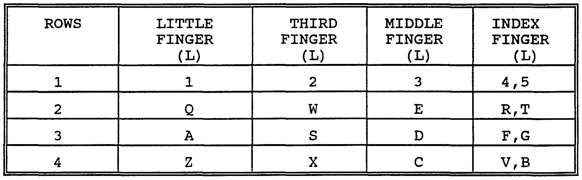
- the fingers on the left hand operate the following keys:
- the fingers on the right hand operate the following keys:
- the trainee must therefore learn, not only the location of each key, but also must learn the stroking technique for which each key is to be actuated on a finger by finger basis.
- the finger to key relationship for the left hand is as follows:
- the finger to key relationship for the right hand is as follows:
- the individual fingers of a user start on different home keys and then travel quickly and instinctively to a plurality of different positions.
- the index finger of each hand must travel from a rest position to seven different keys. Training the fingers to move from the home keys to the target keys, and then back again, requires practice repeatedly, until the fingers move instinctively from key to key in an extremely rapid and accurate manner.
- the touch typing technique requires trainees to learn the complex stroking patterns associated with moving their fingers across the keyboard in a rapid accurate manner, until an acceptable level of entry speed can be achieved with few or no errors in an instinctive manner.
- entry speed is generally limited to no more than three to five strokes a second, even after lengthy training.
- the user/operator should be able to enter information as rapidly as when using a conventional keyboard arrangement, and should not be required to undergo extensive and time consuming training in order to use the keyboard arrangement in a rapid data entry manner.
- the principal object of the present invention is to provide a new and improved keyboard arrangement and method of using it, to not only relieve unwanted physical stress, but also to enable a skilled user to do keyboard entry at a high rate of speed with an acceptable degree of accuracy.
- a new and improved keyboard apparatus having two spaced apart clusters or groups of character keys.
- Each cluster or group is configured in an elongated rectangularly shaped arrangement.
- the clusters or groups are angularly displaced between their transverse dimensions by an angle ⁇ of about 31° to about 36°.
- Each group of character keys is arranged in a series of spaced apart staggered rows of discrete character keys and includes a common V- shaped space bar key bridging the two clusters.
- character indicia is disposed on the top surface of selected ones of the keys and is angularly displaced thereon by an angle of about ⁇ /2.
- FIG. 1 is a top plan view of a keyboard apparatus which is constructed in accordance with the present invention, showing in phantom line the keyboard apparatus disposed at a different location on the supporting surface;
- FIG. 2 is an enlarged side elevational view of the keyboard apparatus of FIG. 1;
- FIG. 3 is a top plan view of another keyboard apparatus, which is also constructed in accordance with the present invention shown with a keyboard cradle also being constructed according to the present invention;
- FIG. 4 is a sectional view of the keyboard apparatus and keyboard cradle unit of FIG. 3 taken substantially on lines 4-4 thereof;
- FIG. 5 is a diagrammatic view of the keyboard apparatus of FIG. 1 showing the angular relationship between individual character keys and character key groupings, and
- FIGS. 1 and 2 there is shown an ergonomic keyboard apparatus 10, which is constructed in accordance with the present invention and which is illustrated positioned on a stationary surface, such as a work station surface 12.
- the keyboard apparatus 10 generally comprises a housing unit 13 ( FIG. 2) which is adapted for positioning on the surface 12.
- the keyboard apparatus 10 also includes a set of character keys projecting upwardly from a face plate 18.
- the character keys are arranged in a pair of spaced apart character key groupings 14 and 16 where each grouping includes a large number of single discrete keys for producing and controlling the entry of alphanumeric characters into a computer or other such equipment (not shown) .
- each grouping includes a large number of single discrete keys for producing and controlling the entry of alphanumeric characters into a computer or other such equipment (not shown) .
- the two groupings 14 and 16 are disposed at an angle ⁇ relative to one another, as indicated in FIG. 5, to relieve physical stress of the user.
- the character keys in the left grouping 14 of keys are arranged to facilitate familiar touch typing techniques for the left hand.
- the keys of the right grouping 16 are arranged to facilitate touch typing techniques for the right hand. Because the character keys are arranged according to a key group to finger type arrangement, there is no need for a user to make keystrokes from one grouping of character keys to the other grouping of character keys.
- a user commences using the keyboard apparatus 10 by placing his or her fingers in a manner similar to familiar touch typing techniques. The user then adjusts the keyboard housing 13 a sufficient distance from the edge of the work station 12 so that his or her wrists and hands are maintained in a straight and aligned relationship to one another to orient the keyboard in a position for comfortable and physiologically safe operation by the user. The user then presses the character keys in seriatim. In this regard, whenever the user depresses one of the character keys, an electrical signal is generated by the keyboard electronics (not shown) which is indicative of a character code that is based on the American Standard Code for Information Interchange (ASCII) .
- ASCII American Standard Code for Information Interchange
- ASCII codes are well known to those skilled in the art and consist of 7-bit coded characters used for information exchange between data processing systems, data communication systems and associated equipment. More particularly, the ASCII set consists of control characters and alphanumeric characters for producing a written language.
- the depression of the individual character keys produces an ASCII code
- other codes or other means such as mechanical linkages as used in mechanical typewriters could be utilized for causing a written language to be produced in response to a user depressing the character keys in seriatim.
- the housing 13 in generally V shaped, and includes a generally rectangular or elongated shaped left section 50, and a generally rectangular or elongated shaped right section 51.
- the character keys in the left section 50 are disposed at an angle ⁇ relative the right section 51, where the angle ⁇ is between the transverse dimensions of the two groupings 14 and 16.
- the angle ⁇ is at about 26° to 36°.
- a more preferred angle ⁇ is at about 31° to 36°; and the most preferred angle ⁇ is about 31°.
- the angle ⁇ between the groupings 14 and 16 enable the hands and wrists of the user to be aligned coextensively thus reducing, if not substantially eliminating physical stress on the hands, wrists, arms, shoulders and back muscles of the user.
- the left grouping 14 generally comprises a set of character keys 100-126 (FIG.
- the right grouping 16 generally comprises a set of characters keys 127-158 that are mounted substantially within an area of the housing 13 defined by a right side transverse line 41 disposed parallel and spaced apart from the right edge 13R portion of the housing 13, a left side transverse line 43 disposed parallel and spaced apart from the line 41, and a pair of parallel spaced apart longitudinal lines 45 and
- selected ones of the character keys include character indica, such as a character indicia 146 and 203 to help facilitate easy recognition of the individual character keys.
- the character indica, such as indicia 146 is angularly disposed along the transverse dimension of the grouping rotated by a sufficient angle ⁇ /2 to facilitate easy recognition of the character indica.
- a user may quickly and easily place his or her fingers on the familiar keys utilized in touch typing techniques.
- the character keys 100-123 are arranged in four staggered rows A-D with a fifth row E dedicated to selected function keys 124- 126.
- a space bar key 159 is disposed intermediate the left grouping 14 and the right grouping 16.
- the configuration or arrangement of the keys 100-123 are substantially similar to part of a conventional QWERTY keyboard layout as will be explained hereinafter in greater detail.
- character keys 100, 106, 112, 118 and 124 are aligned along their left side edges in a transverse column along line 40 (FIG. 5) .
- Character key 100 is substantially similar in size and shape as keys 101-105, where keys 100-105 are distinguishable from one another by character indicia, disposed on the top surface of each key such as a character indicia 202 disposed on key 112.
- character key 106 is approximately 20% wider than character key 100
- character key 112 is approximately 50% wider than character key 100
- character key 118 is approximately twice the width of character key 106. Due to the increasing size difference between character keys 100, 106, 112, and 118, the character rows A, B, C and D are staggered from one another.
- the indicia disposed on the top surface of each of the character keys is canted or skewed at an angle ⁇ /2 along the transverse dimension of the grouping 14.
- the character indicia is disposed in more familiar touch typing orientation to facilitate easy recognition by a user of the keyboard.
- the character keys 100-126 also contain character indicia including function indicia that corresponds to the characters produced by a user manipulating the left hand digits in a familiar touch typing technique.
- the character keys 127-158 are arranged in four straight longitudinal rows A 7 to D' with a fifth row E' dedicated to selected function keys 155 to 158.
- the rows A 7 to E' correspond to rows A to E in the left grouping 14.
- the character keys 134, 142, 149, 155 and 158 are aligned along their right side edges in a transverse column along phantom line 41 (FIG. 5) .
- the character keys in grouping 16 are also arranged in columns, with staggered rows.
- the character keys 127-158 include the character indicia including function indicia corresponding to the characters produced by the manipulation of the right hand digits of the user during touch typing techniques.
- the character indicia thereon is canted by an angle ⁇ /2 along the transverse dimension of the grouping 16.
- numeric key 127 is shown in the right grouping 16, it is contemplated within the scope of the present invention that key 127 may be placed in row A adjacent to key 105. While this positioning of the key 130 in row A would result in a finger to grouping incongruity, one skilled in the art would understand that a person skilled in touch typing techniques would need only to learn one modified keystroke relative to standard touch typing techniques. Instead of reaching the index finger of the right hand to a numeric key such as the key 128 that is immediately adjacent to a numeric key 127, the typist would need to extend his or her finger stretch with the right index finger for a numeric key adjacent to key 105 that is only a slightly further distance.
- the modified stroking motion would be substantially the same as used in familiar touch typing techniques.
- a skilled operator could easily master the keyboard apparatus 10 and secure the same or greater data entry speed with fewer errors due to relative positions of the grouping 12 and 14 which help aligning the hand and wrist disposed on each respective arm of a user.
- the space bar 159 is generally V-shaped and extends between or bridges the two key grouping 14 and 16.
- the space bar key 159 includes a left leg portion
- the left leg portion 159L and the right leg portion 159R are integrally joined together at a apex having an angle ⁇ .
- the angle ⁇ is about five times the angle ⁇ .
- the angle ⁇ is between about 154° and about 144°.
- a more preferred angle ⁇ is between about 149° and about 144°; and a most preferred angle ⁇ is about 149°.
- the left leg portion 159L is directly below and adjacent to keys 121 to 123, while the right leg portion 159R is directly below and adjacent to keys 150 to 152.
- key 159 function as a conventional single space bar key.
- the space bar key 159 could be divided into two separate keys, one associated with the left grouping 14 and the other associated with the right grouping 16.
- a skilled touch typist user positions his or her hands in a normal touch typing position relative to the keyboard apparatus 10 for the purpose of entering character data.
- the user positions his or her left hand in co-extending alignment with his or her left wrist and forearm allowing the forearm to rest on the support surface 12.
- the user adjusts the position of the keyboard apparatus 10 on the stationary surface 12 so that the fingers of the user rest comfortably on the normal starting position keys for a touch typist.
- the finger to key placement is made by the user so that the wrists of the user stay in co-extended alignment with the hands of the user relative to the starting position. Should the user require additional support for his or her arms and wrist, the user may position a supporting pad, not shown on the supporting surface 12 under the wrist and forearms of the user. Once the user has properly positioned his or her arms, wrists, hands and fingers, conventional touch typing strokes may be executed for producing written textual material.
- row A consists of six (6) keys 100-105 which are equally spaced apart. Row A is disposed in a parallel spaced apart manner adjacent to a left top edge 13A (FIG. 5) of the housing unit 13. Each of the keys 100-105 in row A are substantially identical in size and shape and are distinguished from one another by the indicia which is disposed on the top surface of each key.
- Key 100 has its left most edge aligned along the phantom line, shown as line 40 (FIG. 5) which defines the left peripheral edge of the grouping 14. In this regard. the left most edge of keys 100, 106, 112, 118 and 124 are aligned against this phantom line 40.
- row B consist of six keys 106-111.
- Keys 106-111 are equally spaced apart from one another and are substantially identical in size and shape except for key 106.
- Key 106 is approximately the width of 1 1/2 of the other standard size keys in row A and functions as a control key.
- Each of the keys 107- ill are distinguished one from another by the indicia which is disposed on the top surface of each key.
- Key 106 is disposed below keys 100 and 101 causing keys 107 to 111 to be staggered or shifted slightly to the right of keys 101 to 105.
- the relationship between keys 101 to 105 and keys 107 to 111 enables familiar touch typing techniques to be used.
- row C consists of six keys 112 to 117.
- Keys 113 to 117 are spaced apart from one another and are substantially identical in size and shape.
- Key 112 is slightly larger than key 106 causing the keys 113 to 117 to be shifted or staggered slightly to the right of keys 107 to 111.
- Keys 113 to 117 are distinguishable from one another by the indicia which it disposed on the top surface of each key.
- row D consists of six keys, 118-123 which are equally spaced apart. Keys 119 through 123 are substantially identical in size and shape and are distinguishable from one another by the indicia which is disposed on the top surface of each key. Key 118 is approximately twice the width of the other keys in row D. Key 123 has its right most edge aligned substantially along the phamton line 42, which defines the right peripheral edge of the grouping 14 as shown in FIG. 5.
- row E consists of three keys 124 to 126.
- Keys 124 and 126 are substantially identical in size and shape and key 125 is substantially similar in size and shape to key 100.
- Each of the keys 125 and 127 is distinguishable from one another by the indicia which is disposed on the top surface of each key.
- the right side grouping 16 of the character keys consists of 32 character keys 127-158 which are arranged in five spaced apart horizonal rows A' to E'.
- the configuration or arrangement of the keys 127 to 158 are substantially similar to part of a conventional QWERTY keyboard layout as will be explained hereinafter in greater detail.
- row A' consists of eight (8) keys 127 to 134 which are equally spaced apart. Row A' is disposed in a parallel spaced apart manner adjacent to a top right edge 13B of the housing unit 13. Each of the keys 127-134 in row A' are substantially identical in size and shape with the exception of key 134. Keys 127 to 133 are distinguished from one another by the indicia which is disposed on the top surface of each key. Key 134 which is disposed at the right end of row A' and adjacent to key 133, is approximately one and one half the width of any of the other keys in row A', such as key 133 and substantially the same height.
- Key 134 has its upper most edge aligned along the phantom line shown as line 47 which defines the top peripheral edge of grouping 16.
- Key 134 has its right edge aligned along the phantom line 41.
- the right edge of keys 134, 142, 149, 155 and 158 are all aligned against the phantom line 41.
- row B 7 consists of eight keys 135 to 142 which are equally spaced apart. Keys 135 to 142 are substantially identical in size and shape. Each of the keys 135 to 142 are distinguishable one from another by the character indicia which is disposed on the top surface of each key. As key 134 is approximately one and one half times wider than any one of the keep in row A' , the character keep 135-142 in row B 7 are staggered to the right of the character keys 127- 133 in row A'.
- row C consists of seven keys 143 to 148 and key 149.
- Keys 143 to 148 are equally spaced apart and are substantially identical in size and shape and are distinguishable from one another by the indicia which is disposed on the top surface of each key.
- the key 149 is approximately the width of two of the character keys in row B 7 .
- the keys 143- 148 in row C 7 are shifted or staggered to the right of keys 135-140 in row B 7 .
- row D 7 consists of six keys 150 to 155 which are equally spaced apart. Keys 150 to 154 are substantially identical in size and shape and are distinguishable from one another by indicia which is disposed on the top surface of each key. Key 155 is elongated in shape and is slightly wider than key 149. In this regard, the keys 150-154 in row D are shifted or stagger slightly to the right of keys 143- 147 in Row C .
- row E 7 consists of three keys 156 to 158. Keys 156 to 158 are equally spaced apart, and are substantially identical in size and shape. The keys 156 to 158 are distinguishable from one another by indicia which is disposed on the top surface of each key.
- the housing 13 includes a left front edge portion 13E and a right front edge portion 13F.
- the left front edge portion 13E and the right front edge portion 13F converge together at an apex defined by an angle ⁇ , where the angle ⁇ is substantial identical to the angle ⁇ .
- FIGS. 3 and 4 there is shown another keyboard apparatus 300 which is constructed in accordance with the present invention and which is shown in operative position with a support unit 302 for helping to support the keyboard apparatus 300 as well as the wrists and arms of a user (not shown) .
- the support unit 302 is also constructed according to the present invention.
- the apparatus 300 generally comprises a housing 313 which is adapted to be positioned on a generally flat stationary surface such as a surface 312.
- the apparatus 300 includes a pair of angularly disposed, generally rectangular groupings of character keys shown generally at 317, disposed intermediate a pair of left and right numerical keyboard pads 330 and 360 respectively.
- the grouping 317 is generally V-shaped and includes, a left side grouping and a right side grouping, shown generally at 314 and 316 respectively.
- the groupings 314 and 316 are configured and arranged in a similar manner to the groupings 14 and 16 of the keyboard apparatus 10 as shown in FIG. 1, and will not be further described.
- the apparatus 300 also includes a row of dedicated key 318A, 318B, 318C and 318D for causing dedicated functions codes to be produced, such as cursor movement functions as controlled by the cross-shaped key 318C.
- the keyboard apparatus 300 operates in a similar manner to the apparatus 10 as herein before described.
- Apparatus 300 includes the pads 330 and 360 which each include a group of special function keys such as key 330-1 and numeric keys, such as numeric key 360-1 respectively.
- special function keys such as special function key 330-1
- numeric key 360-1 a group of special function keys
- an electrical signal is generated by the keyboard electronics (not shown) , which signal is indicative of a character code based on the ASCII codes.
- the housing 313 is generally pentagonally shaped, and generally comprises a rear rectangularly shaped portion 320 and a triangularly shaped portion 321 to form a pentagonally shaped top surface.
- the key pads 330 and 360 are disposed at portion 320, while the grouping 317 is disposed partially in portion 320 and partially in portion 321.
- the rectangular portion 320 includes a left end edge 322 and a right end edge 324.
- the portion 320 also includes a V-shaped front edge 326 extending between the left edge 322 and the right edge 324.
- the portion 326 includes a pair of front edges 323 and 325 extending from end edge 322 and 324 respectively, and converge at an apex.
- the edges 323 and 325 are disposed at an angle ⁇ .
- the angle ⁇ is between about
- a more preferred angle ⁇ is between about 149° and about 144°.
- a most preferred angle ⁇ is about 149°.
- the keyboard pad 330 is a functional keyboard pad and is configured in a generally rectangular shape.
- the pad 330 comprises a group of 20 function keys, such as keys 330-1 and 330-4.
- the keys of the pad 330 are all substantially identical in size and shape, and are distinguishable from one another by character indicia disposed on the top surface of the keys.
- the keys of the pad 330 are arranged in five straight longitudinal rows, and four transverse columns to define a five key by four key matrix.
- the pad 360 is a numeric keyboard pad and is configured in a generally rectangular shape.
- the pad 360 includes a group of 18 substantially identical keys 360-1 to 360-16 and two larger keys 360-17 and 360-18 respectively.
- Keys 360-17 and 360-18 are substantially identical in size and shape, and are disposed at right angles relative to one another.
- Keys 360-1 to 360-16 are distinguishable from one another also by indicia disposed on the top surface of each respective key.
- the numeric keyboard pad 360 is arranged in five straight rows, and four columns.
- the cradle 302 includes a wedged shaped base 306 having a rear upwardly projecting wall or lip 307 terminating in an edge 309, for confining the keyboard 300 on its upper sloping surface 303 of the cradle 302.
- the base 306, is generally rectangular in configuration sloping upwardly from the rear wall 307 toward a user terminating in a stop portion or internal shoulder 308, canted rearwardly at an angle that is substantially parallel with the upwardly projecting wall 307.
- the stop 308 cooperates with the wall 307 ar surface 303 to define a receiving area or well, for the keyboard 300.
- the top surface of the keyboard is caused to be supported from below on the base 306, in a plane disposed at an angle ⁇ relative to the plane of the surface 312 supporting the cradle 302.
- the angle ⁇ is about 0° to 10° .
- a more preferred angle ⁇ is between about 5° to about 10°; and a most preferred angle is about 10°.
- the cradle 302 enables the keyboard 300 to rest therein, with the keys being disposed in a generally downwardly inclined position, from front to rear. In such a position, the hands extend downwardly over the keyboard in a generally unstressed manner.
- the cradle helps to prevent repetitive stress injuries.
- the angle ⁇ achieves this result.
- the cradle 302 enables the user to rest the hands and wrists thereon during keyboard entry.
- the cradle 302 also includes a front enlarged block portion 310 integrally connected to base portion 306, for providing a resting surface for the wrists and hands of a user.
- the base and block portions 306 and 310 are composed of a suitable material that may be easily molded into the general shape of the cradle. Such materials include styrofoam, and other suitable thermoplastic materials, such as polyurethane.
- the cradle 302 also includes a padded V-shaped portion 311.
- the padded portion 311 is a flat sheet and has a pair of spaced apart parallel end walls 341 and 342 (FIG. 3) .
- the padded portion 310 also includes a pair of spaced apart parallel V-shaped front and rear edges 343 and 344 where the rear edge 344 is conformed to a shape complementary to the front edge of the keyboard housing 313.
Abstract
Description


Claims
Applications Claiming Priority (2)
| Application Number | Priority Date | Filing Date | Title |
|---|---|---|---|
| US658,541 | 1976-02-17 | ||
| US07/658,541 US5212473A (en) | 1991-02-21 | 1991-02-21 | Membrane keyboard and method of using same |
Publications (1)
| Publication Number | Publication Date |
|---|---|
| WO1992014612A1 true WO1992014612A1 (en) | 1992-09-03 |
Family
ID=24641675
Family Applications (1)
| Application Number | Title | Priority Date | Filing Date |
|---|---|---|---|
| PCT/US1991/009550 WO1992014612A1 (en) | 1991-02-21 | 1991-12-20 | Ergonomic keyboard apparatus and method of using same |
Country Status (5)
| Country | Link |
|---|---|
| US (1) | US5212473A (en) |
| EP (1) | EP0572487A1 (en) |
| AU (1) | AU1320392A (en) |
| CA (1) | CA2104587A1 (en) |
| WO (1) | WO1992014612A1 (en) |
Cited By (1)
| Publication number | Priority date | Publication date | Assignee | Title |
|---|---|---|---|---|
| US5660488A (en) * | 1993-04-29 | 1997-08-26 | Miller; Timothy M. | Ergonomically condensed QWERTY keyboard |
Families Citing this family (258)
| Publication number | Priority date | Publication date | Assignee | Title |
|---|---|---|---|---|
| US5339097A (en) * | 1986-10-21 | 1994-08-16 | Grant Alan H | Computer keyboard |
| US5416498A (en) * | 1986-10-21 | 1995-05-16 | Ergonomics, Inc. | Prehensile positioning computer keyboard |
| US6701296B1 (en) | 1988-10-14 | 2004-03-02 | James F. Kramer | Strain-sensing goniometers, systems, and recognition algorithms |
| US5631861A (en) | 1990-02-02 | 1997-05-20 | Virtual Technologies, Inc. | Force feedback and texture simulating interface device |
| US5575576A (en) * | 1990-05-25 | 1996-11-19 | Roysden, Jr.; Brunn W. | Keyboard |
| US5889670A (en) | 1991-10-24 | 1999-03-30 | Immersion Corporation | Method and apparatus for tactilely responsive user interface |
| US5269559A (en) * | 1992-04-29 | 1993-12-14 | Davidson Textron Inc. | Horn actuator incorporating a transducer in a steering wheel |
| US5457453A (en) * | 1992-06-15 | 1995-10-10 | Chiu; Wilson L. | Folding keyboard |
| EP0648090A4 (en) | 1992-07-06 | 1995-11-02 | James F Kramer | Determination of kinematically constrained multi-articulated structures. |
| US6400285B1 (en) * | 1992-10-08 | 2002-06-04 | Henry Gifford | Ergonomic keyboard |
| US7345672B2 (en) * | 1992-12-02 | 2008-03-18 | Immersion Corporation | Force feedback system and actuator power management |
| US6801008B1 (en) | 1992-12-02 | 2004-10-05 | Immersion Corporation | Force feedback system and actuator power management |
| US5616897A (en) * | 1993-06-30 | 1997-04-01 | Weber; Michael R. | Flexible keyboard |
| US5701140A (en) * | 1993-07-16 | 1997-12-23 | Immersion Human Interface Corp. | Method and apparatus for providing a cursor control interface with force feedback |
| US5734373A (en) | 1993-07-16 | 1998-03-31 | Immersion Human Interface Corporation | Method and apparatus for controlling force feedback interface systems utilizing a host computer |
| US6437771B1 (en) * | 1995-01-18 | 2002-08-20 | Immersion Corporation | Force feedback device including flexure member between actuator and user object |
| US5805140A (en) | 1993-07-16 | 1998-09-08 | Immersion Corporation | High bandwidth force feedback interface using voice coils and flexures |
| US5739811A (en) * | 1993-07-16 | 1998-04-14 | Immersion Human Interface Corporation | Method and apparatus for controlling human-computer interface systems providing force feedback |
| US5731804A (en) * | 1995-01-18 | 1998-03-24 | Immersion Human Interface Corp. | Method and apparatus for providing high bandwidth, low noise mechanical I/O for computer systems |
| US5642109A (en) * | 1993-07-29 | 1997-06-24 | Crowley; Robert J. | Flexible inflatable multi-chamber signal generator |
| US5459461A (en) * | 1993-07-29 | 1995-10-17 | Crowley; Robert J. | Inflatable keyboard |
| US6022156A (en) * | 1993-12-10 | 2000-02-08 | Blish; Nelson A. | Ergonomic keyboard |
| WO1995020233A1 (en) * | 1994-01-21 | 1995-07-27 | Davidson Textron Inc. | A horn actuator incorporating a transducer in a steering wheel |
| US5623582A (en) | 1994-07-14 | 1997-04-22 | Immersion Human Interface Corporation | Computer interface or control input device for laparoscopic surgical instrument and other elongated mechanical objects |
| US5579238A (en) * | 1994-10-21 | 1996-11-26 | Krugman; Michael | Instrumented computer keyboard for prevention of injury |
| US5666138A (en) | 1994-11-22 | 1997-09-09 | Culver; Craig F. | Interface control |
| US6166723A (en) | 1995-11-17 | 2000-12-26 | Immersion Corporation | Mouse interface device providing force feedback |
| US5684477A (en) * | 1995-07-17 | 1997-11-04 | Smith Myers Communications Limited | Electronic systems interfacing |
| US6697748B1 (en) | 1995-08-07 | 2004-02-24 | Immersion Corporation | Digitizing system and rotary table for determining 3-D geometry of an object |
| US5959613A (en) | 1995-12-01 | 1999-09-28 | Immersion Corporation | Method and apparatus for shaping force signals for a force feedback device |
| USRE39906E1 (en) | 1995-10-26 | 2007-11-06 | Immersion Corporation | Gyro-stabilized platforms for force-feedback applications |
| US6639581B1 (en) | 1995-11-17 | 2003-10-28 | Immersion Corporation | Flexure mechanism for interface device |
| US5825308A (en) | 1996-11-26 | 1998-10-20 | Immersion Human Interface Corporation | Force feedback interface having isotonic and isometric functionality |
| US6704001B1 (en) | 1995-11-17 | 2004-03-09 | Immersion Corporation | Force feedback device including actuator with moving magnet |
| US6100874A (en) * | 1995-11-17 | 2000-08-08 | Immersion Corporation | Force feedback mouse interface |
| EP0864145A4 (en) | 1995-11-30 | 1998-12-16 | Virtual Technologies Inc | Tactile feedback man-machine interface device |
| US6219032B1 (en) * | 1995-12-01 | 2001-04-17 | Immersion Corporation | Method for providing force feedback to a user of an interface device based on interactions of a controlled cursor with graphical elements in a graphical user interface |
| US6028593A (en) * | 1995-12-01 | 2000-02-22 | Immersion Corporation | Method and apparatus for providing simulated physical interactions within computer generated environments |
| US7027032B2 (en) * | 1995-12-01 | 2006-04-11 | Immersion Corporation | Designing force sensations for force feedback computer applications |
| US8508469B1 (en) | 1995-12-01 | 2013-08-13 | Immersion Corporation | Networked applications including haptic feedback |
| US6169540B1 (en) | 1995-12-01 | 2001-01-02 | Immersion Corporation | Method and apparatus for designing force sensations in force feedback applications |
| US6078308A (en) * | 1995-12-13 | 2000-06-20 | Immersion Corporation | Graphical click surfaces for force feedback applications to provide user selection using cursor interaction with a trigger position within a boundary of a graphical object |
| US6161126A (en) | 1995-12-13 | 2000-12-12 | Immersion Corporation | Implementing force feedback over the World Wide Web and other computer networks |
| US6300936B1 (en) | 1997-11-14 | 2001-10-09 | Immersion Corporation | Force feedback system including multi-tasking graphical host environment and interface device |
| US6750877B2 (en) | 1995-12-13 | 2004-06-15 | Immersion Corporation | Controlling haptic feedback for enhancing navigation in a graphical environment |
| SE519661C2 (en) * | 1996-02-23 | 2003-03-25 | Immersion Corp | Pointing devices and method for marking graphic details on a display with sensory feedback upon finding said detail |
| USD381016S (en) * | 1996-03-28 | 1997-07-15 | Microsoft Corporation | Palm rest portion for a keyboard |
| US6374255B1 (en) * | 1996-05-21 | 2002-04-16 | Immersion Corporation | Haptic authoring |
| US7815436B2 (en) | 1996-09-04 | 2010-10-19 | Immersion Corporation | Surgical simulation interface device and method |
| US6929481B1 (en) | 1996-09-04 | 2005-08-16 | Immersion Medical, Inc. | Interface device and method for interfacing instruments to medical procedure simulation systems |
| US6024576A (en) | 1996-09-06 | 2000-02-15 | Immersion Corporation | Hemispherical, high bandwidth mechanical interface for computer systems |
| US5828197A (en) | 1996-10-25 | 1998-10-27 | Immersion Human Interface Corporation | Mechanical interface having multiple grounded actuators |
| US6411276B1 (en) * | 1996-11-13 | 2002-06-25 | Immersion Corporation | Hybrid control of haptic feedback for host computer and interface device |
| US6686911B1 (en) | 1996-11-26 | 2004-02-03 | Immersion Corporation | Control knob with control modes and force feedback |
| US6636197B1 (en) | 1996-11-26 | 2003-10-21 | Immersion Corporation | Haptic feedback effects for control, knobs and other interface devices |
| US6956558B1 (en) | 1998-03-26 | 2005-10-18 | Immersion Corporation | Rotary force feedback wheels for remote control devices |
| US7489309B2 (en) * | 1996-11-26 | 2009-02-10 | Immersion Corporation | Control knob with multiple degrees of freedom and force feedback |
| CA2278726C (en) * | 1997-01-27 | 2004-08-31 | Immersion Corporation | Method and apparatus for providing high bandwidth, realistic force feedback including an improved actuator |
| GB2323331B (en) | 1997-03-21 | 2000-11-22 | Simon Richard Daniel | Collapsible keyboard |
| US5982304A (en) * | 1997-03-24 | 1999-11-09 | International Business Machines Corporation | Piezoelectric switch with tactile response |
| US6020876A (en) | 1997-04-14 | 2000-02-01 | Immersion Corporation | Force feedback interface with selective disturbance filter |
| AU7161598A (en) | 1997-04-21 | 1998-11-13 | Virtual Technologies, Inc. | Goniometer-based body-tracking device and method |
| US7091948B2 (en) * | 1997-04-25 | 2006-08-15 | Immersion Corporation | Design of force sensations for haptic feedback computer interfaces |
| US7472047B2 (en) * | 1997-05-12 | 2008-12-30 | Immersion Corporation | System and method for constraining a graphical hand from penetrating simulated graphical objects |
| US6292174B1 (en) * | 1997-08-23 | 2001-09-18 | Immersion Corporation | Enhanced cursor control using limited-workspace force feedback devices |
| US6252579B1 (en) * | 1997-08-23 | 2001-06-26 | Immersion Corporation | Interface device and method for providing enhanced cursor control with force feedback |
| US6331850B1 (en) | 1997-11-12 | 2001-12-18 | Think Outside, Inc. | Collapsible keyboard |
| US6088019A (en) * | 1998-06-23 | 2000-07-11 | Immersion Corporation | Low cost force feedback device with actuator for non-primary axis |
| US6252583B1 (en) | 1997-11-14 | 2001-06-26 | Immersion Corporation | Memory and force output management for a force feedback system |
| US6448977B1 (en) * | 1997-11-14 | 2002-09-10 | Immersion Corporation | Textures and other spatial sensations for a relative haptic interface device |
| US6256011B1 (en) | 1997-12-03 | 2001-07-03 | Immersion Corporation | Multi-function control device with force feedback |
| EP1051698B1 (en) * | 1998-01-28 | 2018-01-17 | Immersion Medical, Inc. | Interface device and method for interfacing instruments to vascular access simulation systems |
| GB2349730B (en) * | 1998-01-28 | 2003-04-09 | Ht Medical Systems Inc | Interface device and method for interfacing instruments to medical procedure simulation system |
| US6536966B1 (en) | 1998-03-18 | 2003-03-25 | Robert Brown Butler | Expandable keyboard for small computers and the like |
| US6068417A (en) * | 1998-03-18 | 2000-05-30 | Butler; Robert B. | Electrical key connection for expandable keyboard |
| US20080055241A1 (en) * | 1998-03-26 | 2008-03-06 | Immersion Corporation | Systems and Methods for Haptic Feedback Effects for Control Knobs |
| US6067077A (en) | 1998-04-10 | 2000-05-23 | Immersion Corporation | Position sensing for force feedback devices |
| US6704683B1 (en) | 1998-04-28 | 2004-03-09 | Immersion Corporation | Direct velocity estimation for encoders using nonlinear period measurement |
| US6697043B1 (en) | 1999-12-21 | 2004-02-24 | Immersion Corporation | Haptic interface device and actuator assembly providing linear haptic sensations |
| US6184868B1 (en) | 1998-09-17 | 2001-02-06 | Immersion Corp. | Haptic feedback control devices |
| US6429846B2 (en) * | 1998-06-23 | 2002-08-06 | Immersion Corporation | Haptic feedback for touchpads and other touch controls |
| US6707443B2 (en) | 1998-06-23 | 2004-03-16 | Immersion Corporation | Haptic trackball device |
| US6686901B2 (en) | 1998-06-23 | 2004-02-03 | Immersion Corporation | Enhancing inertial tactile feedback in computer interface devices having increased mass |
| US6717573B1 (en) | 1998-06-23 | 2004-04-06 | Immersion Corporation | Low-cost haptic mouse implementations |
| US7038667B1 (en) | 1998-10-26 | 2006-05-02 | Immersion Corporation | Mechanisms for control knobs and other interface devices |
| US7084884B1 (en) | 1998-11-03 | 2006-08-01 | Immersion Corporation | Graphical object interactions |
| US6218966B1 (en) * | 1998-11-05 | 2001-04-17 | International Business Machines Corporation | Tactile feedback keyboard |
| US6939065B2 (en) | 1998-11-18 | 2005-09-06 | Brunn Wall Roysden, Jr. | Keyboard with interleaved computer components |
| JP2000267785A (en) * | 1999-03-15 | 2000-09-29 | Alps Electric Co Ltd | Keyboard device |
| US6734809B1 (en) * | 1999-04-02 | 2004-05-11 | Think Outside, Inc. | Foldable keyboard |
| US7061466B1 (en) | 1999-05-07 | 2006-06-13 | Immersion Corporation | Force feedback device including single-phase, fixed-coil actuators |
| US6762745B1 (en) | 1999-05-10 | 2004-07-13 | Immersion Corporation | Actuator control providing linear and continuous force output |
| US6903721B2 (en) | 1999-05-11 | 2005-06-07 | Immersion Corporation | Method and apparatus for compensating for position slip in interface devices |
| US6982696B1 (en) | 1999-07-01 | 2006-01-03 | Immersion Corporation | Moving magnet actuator for providing haptic feedback |
| US8169402B2 (en) * | 1999-07-01 | 2012-05-01 | Immersion Corporation | Vibrotactile haptic feedback devices |
| US7561142B2 (en) | 1999-07-01 | 2009-07-14 | Immersion Corporation | Vibrotactile haptic feedback devices |
| DE20022244U1 (en) * | 1999-07-01 | 2001-11-08 | Immersion Corp | Control of vibrotactile sensations for haptic feedback devices |
| US6564168B1 (en) * | 1999-09-14 | 2003-05-13 | Immersion Corporation | High-resolution optical encoder with phased-array photodetectors |
| DE20080209U1 (en) * | 1999-09-28 | 2001-08-09 | Immersion Corp | Control of haptic sensations for interface devices with vibrotactile feedback |
| US6680729B1 (en) | 1999-09-30 | 2004-01-20 | Immersion Corporation | Increasing force transmissibility for tactile feedback interface devices |
| US7050955B1 (en) | 1999-10-01 | 2006-05-23 | Immersion Corporation | System, method and data structure for simulated interaction with graphical objects |
| US6693626B1 (en) | 1999-12-07 | 2004-02-17 | Immersion Corporation | Haptic feedback using a keyboard device |
| US7324019B2 (en) * | 2000-01-03 | 2008-01-29 | Levenson David J | Adjustable ergonomic keyboard for use with stationary palm and elements thereof |
| US6822635B2 (en) * | 2000-01-19 | 2004-11-23 | Immersion Corporation | Haptic interface for laptop computers and other portable devices |
| US6739774B1 (en) | 2000-02-01 | 2004-05-25 | Rast Associates, Llc | Expandable and contractible keyboard with adjustable key sizes |
| KR100828528B1 (en) | 2000-02-01 | 2008-05-13 | 알에이에스티 어소시에이츠, 엘엘씨 | Expandable and contractible keyboard with adjustable key sizes |
| US7965276B1 (en) | 2000-03-09 | 2011-06-21 | Immersion Corporation | Force output adjustment in force feedback devices based on user contact |
| US6817973B2 (en) * | 2000-03-16 | 2004-11-16 | Immersion Medical, Inc. | Apparatus for controlling force for manipulation of medical instruments |
| JP2001283672A (en) * | 2000-03-31 | 2001-10-12 | Mitsumi Electric Co Ltd | Input device for game controller |
| US6924787B2 (en) * | 2000-04-17 | 2005-08-02 | Immersion Corporation | Interface for controlling a graphical image |
| US6578436B1 (en) * | 2000-05-16 | 2003-06-17 | Fidelica Microsystems, Inc. | Method and apparatus for pressure sensing |
| US7316167B2 (en) * | 2000-05-16 | 2008-01-08 | Fidelica, Microsystems, Inc. | Method and apparatus for protection of contour sensing devices |
| EP2385518A3 (en) | 2000-05-24 | 2012-02-15 | Immersion Medical, Inc. | Haptic devices using electroactive polymers |
| US7159008B1 (en) | 2000-06-30 | 2007-01-02 | Immersion Corporation | Chat interface with haptic feedback functionality |
| US7233476B2 (en) | 2000-08-11 | 2007-06-19 | Immersion Corporation | Actuator thermal protection in haptic feedback devices |
| US6906697B2 (en) | 2000-08-11 | 2005-06-14 | Immersion Corporation | Haptic sensations for tactile feedback interface devices |
| US7182691B1 (en) | 2000-09-28 | 2007-02-27 | Immersion Corporation | Directional inertial tactile feedback using rotating masses |
| US6995744B1 (en) | 2000-09-28 | 2006-02-07 | Immersion Corporation | Device and assembly for providing linear tactile sensations |
| WO2002027705A1 (en) | 2000-09-28 | 2002-04-04 | Immersion Corporation | Directional tactile feedback for haptic feedback interface devices |
| US7084854B1 (en) * | 2000-09-28 | 2006-08-01 | Immersion Corporation | Actuator for providing tactile sensations and device for directional tactile sensations |
| KR100350493B1 (en) * | 2000-10-26 | 2002-08-28 | 삼성전자 주식회사 | Portable folding-type radiotelephone with cone-type hinge means |
| US6781077B2 (en) | 2000-12-14 | 2004-08-24 | Think Outside, Inc. | Keyswitch and actuator structure |
| US6911901B2 (en) * | 2000-12-20 | 2005-06-28 | New Transducers Limited | Multi-functional vibro-acoustic device |
| US7567232B2 (en) | 2001-03-09 | 2009-07-28 | Immersion Corporation | Method of using tactile feedback to deliver silent status information to a user of an electronic device |
| US9625905B2 (en) * | 2001-03-30 | 2017-04-18 | Immersion Corporation | Haptic remote control for toys |
| US7202851B2 (en) * | 2001-05-04 | 2007-04-10 | Immersion Medical Inc. | Haptic interface for palpation simulation |
| US6879317B2 (en) | 2001-05-11 | 2005-04-12 | Brian P. Quinn | Collapsible data entry panel |
| US20050176665A1 (en) * | 2001-05-18 | 2005-08-11 | Sirna Therapeutics, Inc. | RNA interference mediated inhibition of hairless (HR) gene expression using short interfering nucleic acid (siNA) |
| IL143255A (en) | 2001-05-20 | 2015-09-24 | Simbionix Ltd | Endoscopic ultrasonography simulation |
| DE10126670A1 (en) * | 2001-06-01 | 2002-12-05 | Bayerische Motoren Werke Ag | Electric circuit switch for a motor vehicle comprises vibration or audible signal from piezoelectric element used in touch-pad to generate operating signal |
| US6937033B2 (en) | 2001-06-27 | 2005-08-30 | Immersion Corporation | Position sensor with resistive element |
| US7056123B2 (en) * | 2001-07-16 | 2006-06-06 | Immersion Corporation | Interface apparatus with cable-driven force feedback and grounded actuators |
| US7877243B2 (en) * | 2001-07-16 | 2011-01-25 | Immersion Corporation | Pivotable computer interface |
| US7154470B2 (en) * | 2001-07-17 | 2006-12-26 | Immersion Corporation | Envelope modulator for haptic feedback devices |
| US8364342B2 (en) | 2001-07-31 | 2013-01-29 | Immersion Corporation | Control wheel with haptic feedback |
| US6940490B1 (en) * | 2001-08-27 | 2005-09-06 | Palmone, Inc. | Raised keys on a miniature keyboard |
| US7151432B2 (en) * | 2001-09-19 | 2006-12-19 | Immersion Corporation | Circuit and method for a switch matrix and switch sensing |
| US6933920B2 (en) * | 2001-09-24 | 2005-08-23 | Immersion Corporation | Data filter for haptic feedback devices having low-bandwidth communication links |
| US7623114B2 (en) | 2001-10-09 | 2009-11-24 | Immersion Corporation | Haptic feedback sensations based on audio output from computer devices |
| US6703550B2 (en) | 2001-10-10 | 2004-03-09 | Immersion Corporation | Sound data output and manipulation using haptic feedback |
| AU2002348399A1 (en) * | 2001-10-23 | 2003-07-09 | Immersion Corporation | Method of using tactile feedback to deliver silent status information to a user of an electronic device |
| US6833846B2 (en) | 2001-10-24 | 2004-12-21 | Immersion Corporation | Control methods for the reduction of limit cycle oscillations for haptic devices with displacement quantization |
| EP1440414B1 (en) * | 2001-10-30 | 2016-08-17 | Immersion Corporation | Methods and apparatus for providing haptic feedback in interacting with virtual pets |
| US6683437B2 (en) | 2001-10-31 | 2004-01-27 | Immersion Corporation | Current controlled motor amplifier system |
| US7535454B2 (en) | 2001-11-01 | 2009-05-19 | Immersion Corporation | Method and apparatus for providing haptic feedback |
| KR101289110B1 (en) | 2001-11-01 | 2013-08-07 | 임머숀 코퍼레이션 | Method and apparatus for providing tactile sensations |
| AU2002360497A1 (en) | 2001-12-06 | 2003-06-23 | Rast Associates, Llc | Expandable and contractible keyboard device |
| US6904823B2 (en) * | 2002-04-03 | 2005-06-14 | Immersion Corporation | Haptic shifting devices |
| US7161580B2 (en) * | 2002-04-25 | 2007-01-09 | Immersion Corporation | Haptic feedback using rotary harmonic moving mass |
| US7369115B2 (en) * | 2002-04-25 | 2008-05-06 | Immersion Corporation | Haptic devices having multiple operational modes including at least one resonant mode |
| US6748604B2 (en) * | 2002-05-30 | 2004-06-15 | Finger Fitting Products, Inc. | Glove massager |
| US20040040800A1 (en) * | 2002-07-31 | 2004-03-04 | George Anastas | System and method for providing passive haptic feedback |
| DE10243600A1 (en) * | 2002-09-19 | 2004-04-01 | Delphi Technologies, Inc., Troy | Electrical switch |
| WO2004036405A2 (en) * | 2002-10-15 | 2004-04-29 | Immersion Corporation | Products and processes for providing force sensations in a user interface |
| GB2410316B (en) * | 2002-10-20 | 2007-03-21 | Immersion Corp | System and method for providing rotational haptic feedback |
| US6965370B2 (en) | 2002-11-19 | 2005-11-15 | Immersion Corporation | Haptic feedback devices for simulating an orifice |
| US8830161B2 (en) | 2002-12-08 | 2014-09-09 | Immersion Corporation | Methods and systems for providing a virtual touch haptic effect to handheld communication devices |
| US7769417B2 (en) | 2002-12-08 | 2010-08-03 | Immersion Corporation | Method and apparatus for providing haptic feedback to off-activating area |
| US8059088B2 (en) | 2002-12-08 | 2011-11-15 | Immersion Corporation | Methods and systems for providing haptic messaging to handheld communication devices |
| WO2004053644A2 (en) | 2002-12-08 | 2004-06-24 | Immersion Corporation | Using haptic effects to enhance information content in communications |
| US7336266B2 (en) * | 2003-02-20 | 2008-02-26 | Immersion Corproation | Haptic pads for use with user-interface devices |
| WO2004097788A1 (en) * | 2003-04-28 | 2004-11-11 | Immersion Corporation | Systems and methods for user interfaces designed for rotary input devices |
| US7280095B2 (en) * | 2003-04-30 | 2007-10-09 | Immersion Corporation | Hierarchical methods for generating force feedback effects |
| DE112004000918B4 (en) * | 2003-05-30 | 2018-05-17 | Immersion Corp. | Device with a haptic effect generator |
| US7477237B2 (en) * | 2003-06-03 | 2009-01-13 | Immersion Corporation | Systems and methods for providing a haptic manipulandum |
| GB2418475B (en) | 2003-06-09 | 2007-10-24 | Immersion Corp | Interactive gaming systems with haptic feedback |
| US7850456B2 (en) | 2003-07-15 | 2010-12-14 | Simbionix Ltd. | Surgical simulation device, system and method |
| DE10340188A1 (en) * | 2003-09-01 | 2005-04-07 | Siemens Ag | Screen with a touch-sensitive user interface for command input |
| TWI256015B (en) * | 2003-11-17 | 2006-06-01 | Weltrend Semiconductor Inc | Computer keyboard capable of measuring the pressure pressed on the key of the keyboard |
| US8164573B2 (en) * | 2003-11-26 | 2012-04-24 | Immersion Corporation | Systems and methods for adaptive interpretation of input from a touch-sensitive input device |
| US7742036B2 (en) * | 2003-12-22 | 2010-06-22 | Immersion Corporation | System and method for controlling haptic devices having multiple operational modes |
| US7112737B2 (en) * | 2003-12-31 | 2006-09-26 | Immersion Corporation | System and method for providing a haptic effect to a musical instrument |
| US7283120B2 (en) | 2004-01-16 | 2007-10-16 | Immersion Corporation | Method and apparatus for providing haptic feedback having a position-based component and a predetermined time-based component |
| US7205981B2 (en) * | 2004-03-18 | 2007-04-17 | Immersion Corporation | Method and apparatus for providing resistive haptic feedback using a vacuum source |
| US7505030B2 (en) * | 2004-03-18 | 2009-03-17 | Immersion Medical, Inc. | Medical device and procedure simulation |
| US7289106B2 (en) | 2004-04-01 | 2007-10-30 | Immersion Medical, Inc. | Methods and apparatus for palpation simulation |
| US7522152B2 (en) * | 2004-05-27 | 2009-04-21 | Immersion Corporation | Products and processes for providing haptic feedback in resistive interface devices |
| WO2006017254A1 (en) * | 2004-07-12 | 2006-02-16 | Immersion Corporation | System and method for increasing sensor resolution using interpolation |
| US7198137B2 (en) * | 2004-07-29 | 2007-04-03 | Immersion Corporation | Systems and methods for providing haptic feedback with position sensing |
| US8441433B2 (en) * | 2004-08-11 | 2013-05-14 | Immersion Corporation | Systems and methods for providing friction in a haptic feedback device |
| US9495009B2 (en) * | 2004-08-20 | 2016-11-15 | Immersion Corporation | Systems and methods for providing haptic effects |
| US8013847B2 (en) * | 2004-08-24 | 2011-09-06 | Immersion Corporation | Magnetic actuator for providing haptic feedback |
| US8803796B2 (en) | 2004-08-26 | 2014-08-12 | Immersion Corporation | Products and processes for providing haptic feedback in a user interface |
| US20060049010A1 (en) * | 2004-09-03 | 2006-03-09 | Olien Neil T | Device and method for providing resistive and vibrotactile effects |
| US8002089B2 (en) * | 2004-09-10 | 2011-08-23 | Immersion Corporation | Systems and methods for providing a haptic device |
| US7245202B2 (en) * | 2004-09-10 | 2007-07-17 | Immersion Corporation | Systems and methods for networked haptic devices |
| US9046922B2 (en) * | 2004-09-20 | 2015-06-02 | Immersion Corporation | Products and processes for providing multimodal feedback in a user interface device |
| US7764268B2 (en) * | 2004-09-24 | 2010-07-27 | Immersion Corporation | Systems and methods for providing a haptic device |
| JP4860625B2 (en) * | 2004-10-08 | 2012-01-25 | イマージョン コーポレーション | Haptic feedback for simulating buttons and scrolling motion on touch input devices |
| WO2006071449A1 (en) | 2004-11-30 | 2006-07-06 | Immersion Corporation | Systems and methods for controlling a resonant device for generating vibrotactile haptic effects |
| US7825903B2 (en) * | 2005-05-12 | 2010-11-02 | Immersion Corporation | Method and apparatus for providing haptic effects to a touch panel |
| US7394030B2 (en) | 2005-06-02 | 2008-07-01 | Palm, Inc. | Small form-factor keyboard using keys with offset peaks and pitch variations |
| DE102007016083A1 (en) * | 2006-05-31 | 2007-12-06 | Mizukawa, Suehiro, Settsu | Method and device for bending a knife element |
| US8989822B2 (en) | 2006-09-08 | 2015-03-24 | Qualcomm Incorporated | Keypad assembly for use on a contoured surface of a mobile computing device |
| US8543338B2 (en) | 2007-01-16 | 2013-09-24 | Simbionix Ltd. | System and method for performing computerized simulations for image-guided procedures using a patient specific model |
| WO2008087629A2 (en) | 2007-01-16 | 2008-07-24 | Simbionix Ltd. | Preoperative surgical simulation |
| US8315652B2 (en) * | 2007-05-18 | 2012-11-20 | Immersion Corporation | Haptically enabled messaging |
| US9423875B2 (en) | 2008-01-04 | 2016-08-23 | Tactus Technology, Inc. | Dynamic tactile interface with exhibiting optical dispersion characteristics |
| US9372565B2 (en) | 2008-01-04 | 2016-06-21 | Tactus Technology, Inc. | Dynamic tactile interface |
| US9128525B2 (en) | 2008-01-04 | 2015-09-08 | Tactus Technology, Inc. | Dynamic tactile interface |
| US8922503B2 (en) * | 2008-01-04 | 2014-12-30 | Tactus Technology, Inc. | User interface system |
| US9298261B2 (en) | 2008-01-04 | 2016-03-29 | Tactus Technology, Inc. | Method for actuating a tactile interface layer |
| US9274612B2 (en) | 2008-01-04 | 2016-03-01 | Tactus Technology, Inc. | User interface system |
| US8553005B2 (en) | 2008-01-04 | 2013-10-08 | Tactus Technology, Inc. | User interface system |
| US8154527B2 (en) | 2008-01-04 | 2012-04-10 | Tactus Technology | User interface system |
| US9063627B2 (en) | 2008-01-04 | 2015-06-23 | Tactus Technology, Inc. | User interface and methods |
| US8970403B2 (en) | 2008-01-04 | 2015-03-03 | Tactus Technology, Inc. | Method for actuating a tactile interface layer |
| US8947383B2 (en) | 2008-01-04 | 2015-02-03 | Tactus Technology, Inc. | User interface system and method |
| US8243038B2 (en) | 2009-07-03 | 2012-08-14 | Tactus Technologies | Method for adjusting the user interface of a device |
| US9588683B2 (en) | 2008-01-04 | 2017-03-07 | Tactus Technology, Inc. | Dynamic tactile interface |
| US8570295B2 (en) | 2008-01-04 | 2013-10-29 | Tactus Technology, Inc. | User interface system |
| US9612659B2 (en) | 2008-01-04 | 2017-04-04 | Tactus Technology, Inc. | User interface system |
| US8456438B2 (en) | 2008-01-04 | 2013-06-04 | Tactus Technology, Inc. | User interface system |
| US8922502B2 (en) * | 2008-01-04 | 2014-12-30 | Tactus Technology, Inc. | User interface system |
| US9552065B2 (en) | 2008-01-04 | 2017-01-24 | Tactus Technology, Inc. | Dynamic tactile interface |
| US9367132B2 (en) | 2008-01-04 | 2016-06-14 | Tactus Technology, Inc. | User interface system |
| US8922510B2 (en) | 2008-01-04 | 2014-12-30 | Tactus Technology, Inc. | User interface system |
| US8547339B2 (en) | 2008-01-04 | 2013-10-01 | Tactus Technology, Inc. | System and methods for raised touch screens |
| US9557915B2 (en) | 2008-01-04 | 2017-01-31 | Tactus Technology, Inc. | Dynamic tactile interface |
| US9760172B2 (en) | 2008-01-04 | 2017-09-12 | Tactus Technology, Inc. | Dynamic tactile interface |
| US9052790B2 (en) | 2008-01-04 | 2015-06-09 | Tactus Technology, Inc. | User interface and methods |
| US9720501B2 (en) | 2008-01-04 | 2017-08-01 | Tactus Technology, Inc. | Dynamic tactile interface |
| US20090195512A1 (en) * | 2008-02-05 | 2009-08-06 | Sony Ericsson Mobile Communications Ab | Touch sensitive display with tactile feedback |
| US20100013613A1 (en) * | 2008-07-08 | 2010-01-21 | Jonathan Samuel Weston | Haptic feedback projection system |
| US7969287B2 (en) * | 2008-08-18 | 2011-06-28 | Visteon Global Technologies, Inc. | Haptic effect control system |
| US9588684B2 (en) | 2009-01-05 | 2017-03-07 | Tactus Technology, Inc. | Tactile interface for a computing device |
| US8760413B2 (en) * | 2009-01-08 | 2014-06-24 | Synaptics Incorporated | Tactile surface |
| CN102483675B (en) | 2009-07-03 | 2015-09-09 | 泰克图斯科技公司 | User interface strengthens system |
| US10068728B2 (en) | 2009-10-15 | 2018-09-04 | Synaptics Incorporated | Touchpad with capacitive force sensing |
| US8624839B2 (en) * | 2009-10-15 | 2014-01-07 | Synaptics Incorporated | Support-surface apparatus to impart tactile feedback |
| US9239623B2 (en) | 2010-01-05 | 2016-01-19 | Tactus Technology, Inc. | Dynamic tactile interface |
| US8619035B2 (en) | 2010-02-10 | 2013-12-31 | Tactus Technology, Inc. | Method for assisting user input to a device |
| KR20130136905A (en) | 2010-04-19 | 2013-12-13 | 택투스 테크놀로지, 아이엔씨. | User interface system |
| WO2012054780A1 (en) | 2010-10-20 | 2012-04-26 | Tactus Technology | User interface system |
| KR20140043697A (en) | 2010-10-20 | 2014-04-10 | 택투스 테크놀로지, 아이엔씨. | User interface system and method |
| US8780060B2 (en) | 2010-11-02 | 2014-07-15 | Apple Inc. | Methods and systems for providing haptic control |
| JP2012133909A (en) * | 2010-12-20 | 2012-07-12 | Sony Corp | Key input device |
| US8309870B2 (en) | 2011-01-04 | 2012-11-13 | Cody George Peterson | Leveled touchsurface with planar translational responsiveness to vertical travel |
| US8912458B2 (en) | 2011-01-04 | 2014-12-16 | Synaptics Incorporated | Touchsurface with level and planar translational travel responsiveness |
| US8847890B2 (en) | 2011-01-04 | 2014-09-30 | Synaptics Incorporated | Leveled touchsurface with planar translational responsiveness to vertical travel |
| US8735755B2 (en) | 2011-03-07 | 2014-05-27 | Synaptics Incorporated | Capacitive keyswitch technologies |
| US9582178B2 (en) | 2011-11-07 | 2017-02-28 | Immersion Corporation | Systems and methods for multi-pressure interaction on touch-sensitive surfaces |
| US9891709B2 (en) | 2012-05-16 | 2018-02-13 | Immersion Corporation | Systems and methods for content- and context specific haptic effects using predefined haptic effects |
| US9245428B2 (en) | 2012-08-02 | 2016-01-26 | Immersion Corporation | Systems and methods for haptic remote control gaming |
| US9218927B2 (en) | 2012-08-06 | 2015-12-22 | Synaptics Incorporated | Touchsurface assembly with level and planar translational responsiveness via a buckling elastic component |
| US9324515B2 (en) | 2012-08-06 | 2016-04-26 | Synaptics Incorporated | Touchsurface assembly utilizing magnetically enabled hinge |
| US9177733B2 (en) | 2012-08-06 | 2015-11-03 | Synaptics Incorporated | Touchsurface assemblies with linkages |
| US9040851B2 (en) | 2012-08-06 | 2015-05-26 | Synaptics Incorporated | Keycap assembly with an interactive spring mechanism |
| WO2014047656A2 (en) | 2012-09-24 | 2014-03-27 | Tactus Technology, Inc. | Dynamic tactile interface and methods |
| US9405417B2 (en) | 2012-09-24 | 2016-08-02 | Tactus Technology, Inc. | Dynamic tactile interface and methods |
| US9904394B2 (en) | 2013-03-13 | 2018-02-27 | Immerson Corporation | Method and devices for displaying graphical user interfaces based on user contact |
| US9384919B2 (en) | 2013-03-14 | 2016-07-05 | Synaptics Incorporated | Touchsurface assembly having key guides formed in a sheet metal component |
| US9213372B2 (en) | 2013-04-19 | 2015-12-15 | Synaptics Incorporated | Retractable keyboard keys |
| US9557813B2 (en) | 2013-06-28 | 2017-01-31 | Tactus Technology, Inc. | Method for reducing perceived optical distortion |
| US20160128275A1 (en) * | 2014-11-12 | 2016-05-12 | Deere & Company | Robotic mower contact detection system |
| TWD195959S (en) * | 2018-05-18 | 2019-02-11 | 大陸商仁寶資訊工業(昆山 | Portion of a keyboard |
| US11822394B2 (en) * | 2021-01-12 | 2023-11-21 | Dell Products L.P. | Information handling system variable feel input device |
| US11914796B1 (en) | 2023-06-27 | 2024-02-27 | Dell Products L.P. | Low acoustic keyboard stabilized key |
Citations (3)
| Publication number | Priority date | Publication date | Assignee | Title |
|---|---|---|---|---|
| US1138474A (en) * | 1914-03-18 | 1915-05-04 | Fritz Heidner | Type-writing machine. |
| US4483634A (en) * | 1980-12-19 | 1984-11-20 | International Standard Electric Corporation | Keyboard arrangement |
| US5040757A (en) * | 1990-10-11 | 1991-08-20 | Benaway Dennis W | Wrist support for use with an office machine having a keyboard |
Family Cites Families (15)
| Publication number | Priority date | Publication date | Assignee | Title |
|---|---|---|---|---|
| CH174678A (en) * | 1934-01-25 | 1935-01-31 | Muther Adolf | Typewriter keyboard. |
| US2527016A (en) * | 1948-11-24 | 1950-10-24 | Loung Pai Yen | Flat platen typewriter with longitudinally projected type strip elements |
| DE1279693B (en) * | 1963-09-28 | 1968-10-10 | Ibm Deutschland | Standard keyboard divided into two mirror-image fields for controlling the drive of functional devices on typewriters and similar machines |
| US3860771A (en) * | 1973-10-29 | 1975-01-14 | Chomerics Inc | Keyboard switch assembly with dome shaped actuator having associated underlying contactor means |
| US3945482A (en) * | 1973-12-14 | 1976-03-23 | Harvey Einbinder | Orthogonal input keyboards |
| DE2501073A1 (en) * | 1974-02-04 | 1975-08-14 | Motorola Inc | CIRCUIT ARRANGEMENT FOR SUPPRESSING SWITCH IMPULSES |
| CH610822A5 (en) * | 1976-06-10 | 1979-05-15 | Adolf Muther | Keyboard on a typewriter |
| US4109118A (en) * | 1976-09-01 | 1978-08-22 | Victor Kley | Keyswitch pad |
| US4113212A (en) * | 1977-06-08 | 1978-09-12 | Paul Coriden | Collapsible electronic calculator stand |
| US4334280A (en) * | 1980-06-09 | 1982-06-08 | Texas Instruments Incorporated | System and method for providing an audible sound and a tactile feedback in an electronic data processing system |
| EP0085645A3 (en) * | 1982-02-02 | 1984-10-31 | ERGOPLIC MAKASHOT (1981) Ltd. | Keyboard apparatus |
| JPS59135536A (en) * | 1983-01-24 | 1984-08-03 | Sharp Corp | Key input device |
| JPS6162117A (en) * | 1984-09-03 | 1986-03-31 | Brother Ind Ltd | Keyboard |
| US5119078A (en) * | 1986-10-21 | 1992-06-02 | Grant Alan H | Computer work station with mnemonic keyboard |
| US4933522A (en) * | 1989-03-07 | 1990-06-12 | Itt Corporation | Flanged snap dome |
-
1991
- 1991-02-21 US US07/658,541 patent/US5212473A/en not_active Expired - Fee Related
- 1991-12-20 AU AU13203/92A patent/AU1320392A/en not_active Abandoned
- 1991-12-20 EP EP92905410A patent/EP0572487A1/en not_active Withdrawn
- 1991-12-20 CA CA002104587A patent/CA2104587A1/en not_active Abandoned
- 1991-12-20 WO PCT/US1991/009550 patent/WO1992014612A1/en not_active Application Discontinuation
Patent Citations (3)
| Publication number | Priority date | Publication date | Assignee | Title |
|---|---|---|---|---|
| US1138474A (en) * | 1914-03-18 | 1915-05-04 | Fritz Heidner | Type-writing machine. |
| US4483634A (en) * | 1980-12-19 | 1984-11-20 | International Standard Electric Corporation | Keyboard arrangement |
| US5040757A (en) * | 1990-10-11 | 1991-08-20 | Benaway Dennis W | Wrist support for use with an office machine having a keyboard |
Non-Patent Citations (1)
| Title |
|---|
| See also references of EP0572487A4 * |
Cited By (1)
| Publication number | Priority date | Publication date | Assignee | Title |
|---|---|---|---|---|
| US5660488A (en) * | 1993-04-29 | 1997-08-26 | Miller; Timothy M. | Ergonomically condensed QWERTY keyboard |
Also Published As
| Publication number | Publication date |
|---|---|
| CA2104587A1 (en) | 1992-08-22 |
| AU1320392A (en) | 1992-09-15 |
| EP0572487A1 (en) | 1993-12-08 |
| US5212473A (en) | 1993-05-18 |
| EP0572487A4 (en) | 1994-01-12 |
Similar Documents
| Publication | Publication Date | Title |
|---|---|---|
| US5302040A (en) | Ergonomic keyboard apparatus and method of using same | |
| US5503484A (en) | Ergonomic keyboard apparatus and method of using same | |
| WO1992014612A1 (en) | Ergonomic keyboard apparatus and method of using same | |
| JP3215419B2 (en) | Ergonomic keyboard device | |
| US4509873A (en) | Alphanumeric section of office machine keyboards | |
| US4917516A (en) | Combination computer keyboard and mouse data entry system | |
| US4913573A (en) | Alpha-numeric keyboard | |
| US5416498A (en) | Prehensile positioning computer keyboard | |
| CA1336418C (en) | One-handed keyboard | |
| US6005496A (en) | Ergonomic keyboard apparatus | |
| US6084576A (en) | User friendly keyboard | |
| US6042282A (en) | Ergonomic keyboard | |
| US5584588A (en) | Computer keyboard layout | |
| WO1994024685A1 (en) | Ergonomic keyboard and pointing apparatus and method | |
| US3805939A (en) | Keyboard actuator | |
| EP0045307B1 (en) | Keyboards and methods of operating keyboards | |
| US5476332A (en) | Symmetrical keyboard apparatus | |
| US4669903A (en) | Bio-mechanical keyboard structure and method | |
| JPH07200121A (en) | Keyboard with incorporated pointer and inclination device | |
| JPH06507741A (en) | keyboard | |
| US6802662B1 (en) | Non-linear ergonomic keyboard | |
| US4762436A (en) | Bio-mechanical neuro-sensory keyboard structure and operating methods | |
| US20020109667A1 (en) | Ergonomic human-computer input device | |
| EP0279553B1 (en) | Alpha-numeric keyboard | |
| US20080106441A1 (en) | Keyboard in the form of a carpet or a mat |
Legal Events
| Date | Code | Title | Description |
|---|---|---|---|
| AK | Designated states |
Kind code of ref document: A1 Designated state(s): AT AU BB BG BR CA CH DE DK ES FI GB HU JP KP KR LK LU MG MW NL NO RO SD SE SU |
|
| AL | Designated countries for regional patents |
Kind code of ref document: A1 Designated state(s): AT BE BF BJ CF CG CH CI CM DE DK ES FR GA GB GN GR IT LU MC ML MR NL SE SN TD TG |
|
| DFPE | Request for preliminary examination filed prior to expiration of 19th month from priority date (pct application filed before 20040101) | ||
| WWE | Wipo information: entry into national phase |
Ref document number: 1992905410 Country of ref document: EP |
|
| WWE | Wipo information: entry into national phase |
Ref document number: 2104586 Country of ref document: CA |
|
| WWP | Wipo information: published in national office |
Ref document number: 1992905410 Country of ref document: EP |
|
| REG | Reference to national code |
Ref country code: DE Ref legal event code: 8642 |
|
| WWW | Wipo information: withdrawn in national office |
Ref document number: 1992905410 Country of ref document: EP |