WO1993025734A1 - Process for the production of uniform yarns via reduced tension-induced slippage - Google Patents

Process for the production of uniform yarns via reduced tension-induced slippage Download PDF

Info

Publication number
WO1993025734A1
WO1993025734A1 PCT/US1992/004643 US9204643W WO9325734A1 WO 1993025734 A1 WO1993025734 A1 WO 1993025734A1 US 9204643 W US9204643 W US 9204643W WO 9325734 A1 WO9325734 A1 WO 9325734A1
Authority
WO
WIPO (PCT)
Prior art keywords
yarn
tension
rolls
wraps
roll
Prior art date
Application number
PCT/US1992/004643
Other languages
French (fr)
Inventor
Ralph Walter Nugent
Original Assignee
E.I. Du Pont De Nemours And Company
Priority date (The priority date is an assumption and is not a legal conclusion. Google has not performed a legal analysis and makes no representation as to the accuracy of the date listed.)
Filing date
Publication date
Application filed by E.I. Du Pont De Nemours And Company filed Critical E.I. Du Pont De Nemours And Company
Priority to AU21873/92A priority Critical patent/AU669115B2/en
Priority to EP92913532A priority patent/EP0644957B1/en
Priority to BR9207146A priority patent/BR9207146A/en
Priority to DE69217394T priority patent/DE69217394T2/en
Priority to ES92913532T priority patent/ES2097915T3/en
Publication of WO1993025734A1 publication Critical patent/WO1993025734A1/en

Links

Classifications

    • DTEXTILES; PAPER
    • D02YARNS; MECHANICAL FINISHING OF YARNS OR ROPES; WARPING OR BEAMING
    • D02JFINISHING OR DRESSING OF FILAMENTS, YARNS, THREADS, CORDS, ROPES OR THE LIKE
    • D02J1/00Modifying the structure or properties resulting from a particular structure; Modifying, retaining, or restoring the physical form or cross-sectional shape, e.g. by use of dies or squeeze rollers
    • D02J1/22Stretching or tensioning, shrinking or relaxing, e.g. by use of overfeed and underfeed apparatus, or preventing stretch
    • D02J1/227Control of the stretching tension; Localisation of the stretching neck; Draw-pins

Definitions

  • the present invention relates to processes for the production of thermoplastic polymer yarns and more particularly relates to manufacturing processes which produce highly uniform thermoplastic polymer yarns.
  • at least one drawing step is either coupled with or performed as a separate step in the manufacturing process. The drawing of the yarns to impart orientation and thereby reduce residual elongation and increase tensile strength requires, in most cases, that the yarn be subjected to a significant tension.
  • the yarn is advanced in a draw zone between sets of rotating rolls including feed rolls and subsequent draw rolls which are rotated at a higher peripheral speed than the feed rolls to impart the desired tension on the yarn.
  • the yarn which is advancing to the feed rolls is usually at a much lower tension than the tension in the draw zone, at least some slippage frequently occurs on the feed rolls and sometimes the draw begins to occur on the rolls. It has been discovered that this slippage and the drawing on the feed rolls can cause variations in the yarn and can affect the suitability of the yarns for end use applications such as in fabrics which are dyed with structure sensitive reactive dyes. When such dyes are used, otherwise undetectable variations in the yarns can be responsible for highly visible non-uniformity in fabric dyeing.
  • Heated jets are sometimes used to reduce drawing tension and this minimizes tension induced slippage as in U.S. Pat. 3,452,130.
  • such jets are not suitable for many types of processes and problems in controlling the uniformity of temperature and friction when these hot jets are used makes the process much more difficult to run and more expensive.
  • the use of snubbing pins to increase pre ⁇ tension is a useful route to minimize tension induced slippage as in U.S. Pat. 2,728,973 and U.S. Pat. 3,752,457 but can sometime also result in filament breakage.
  • One aspect of the invention relates to an improved process in which a thermoplastic polymer yarn is drawn by advancing the yarn into a draw zone between feed roll means and at least one subsequent draw roll means rotating at a higher speed than the feed roll means with the yarn undergoing a tension increase of at least a 30% as the yarn is advanced by the feed roll means into the draw zone.
  • the process of the invention includes spirally advancing the yarn, before the yarn enters the draw zone, along a pair of spaced-apart rolls with the yarn contacting the rolls in successive wraps. At least one of the rolls is driven and has a diameter which increases as the yarn proceeds between at least two of the wraps on the pair of rolls.
  • the wraps each contact the surface of the driven roll over a roll contact area to each define a total wrap angle for the wrap.
  • the number of the wraps on the roll and the diameter of the driven roll at each of the contact areas is selected to increase the tension while preventing a wrap angle in creep for any one of the wraps from being greater than about 90% of the total wrap angle for the wrap.
  • the tension reached in any one of the wraps is prevented from being greater than about 90% of the yarn draw tension of the yarn.
  • the number of the wraps on the roll and the diameter of the driven roll at each of the contact areas are selected to increase the tension while preventing a wrap angle in creep for any one of the wraps from being greater than about 80% of the total wrap angle.
  • both of the rolls of the pair are driven and both have a diameter which increases as the yarn proceeds between at least two of the wraps.
  • an improved process is provided in which a thermoplastic polymer yarn is extruded through and withdrawn from a spinneret and subsequently wound up with the tension on the yarn in at least one step of the process being decreased by a tension release zone tension decrease of at least about 20% in a tension release zone prior to windup.
  • the process in accordance with the invention includes spirally advancing the yarn, before the yarn enters the tension release zone, along a pair of spaced-apart rolls with the yarn contacting the rolls in successive wraps.
  • At least one of the rolls is driven and has a diameter which decreases as the yarn proceeds between at least two of the wraps on the pair of rolls.
  • the wraps each contacting the surface of the driven roll over a roll contact area to each define a total wrap angle for the wrap.
  • the number of the wraps on the roll and the diameter of the driven roll at each of the contact areas is selected to decrease the tension while preventing a wrap angle in creep for any one of the wraps from being greater than about 90% of the total wrap angle for the wrap.
  • the tension release zone tension decrease is greater than about 30%.
  • the number of the wraps on the roll and the diameter of the driven roll at each of the contact areas are selected to decrease the tension while preventing a wrap angle in creep for any one of the wraps from being greater than about 80% of the total wrap angle.
  • both of the rolls of the pair are driven and both have a diameter which decreases as the yarn proceeds between at least two of the wraps.
  • the invention When used in processes for the manufacturing of aliphatic polyamide textile yarns, the invention provides yarns which yield improvements in uniformity which are reflected in the dyeing uniformity of fabrics made from such yarns. The improvements can often be obtained using existing equipment which can be modified for the practice of the present invention.
  • Figure 1 is a diagrammatical illustration of a wrap of yarn advancing in contact with a roll from a zone of lower tension to a zone of higher tension;
  • Figure 2 is a diagrammatical, elevational view of typical nylon fiber coupled spin-draw process employing one form of the process of the present invention for increasing tension in advance of a draw zone;
  • Figures 3a and 3b are enlarged elevational and perspective views, respectively, of apparatus useful for the practice of one form of the present invention for increasing tension in advance of a draw zone;
  • Figures 4a and 4b are enlarged elevational and perspective views, respectively, of apparatus useful for the practice of one form of the present invention for decreasing tension;
  • Figure 5 is a diagrammatical, elevational view of a typical high-speed spinning process for the manufacture of polyester yarn illustrating the use of a process in accordance with the invention for decreasing tension before the yarn is wound up.
  • yarn undergoing a tension change is spirally advanced on a pair of rolls with the yarn contacting the rolls in successive wraps.
  • the yarn is prevented from slipping on the roll by providing a tension level change across the roll for each wrap so that slippage does not occur.
  • the invention is applicable to thermoplastic polymer yarn drawing processes in which the yarn enters a draw zone in which the tension increases by at least about 30%.
  • the invention is also applicable to thermoplastic polymer manufacturing processes in which a yarn is withdrawn from a spinneret and undergoes a tension decrease of at least about 20% at some stage in the process. When used for tension decreases, the process is more advantageously practiced when the tension decrease is at least about 30%.
  • thermoplastic polymer yarn for which the invention is useful include processes for making yarns of thermoplastic polymers including, for example, polyamides such as poly(hexamethylene adipamide) and poly( ⁇ -caproamide) , polyesters, and polyolefins.
  • the invention is most advantageously practiced with aliphatic polyamides such as poly(hexamethylene adipamide) and poly(e-caproamide) and their copolymers.
  • a "wrap angle in creep” for any of the wraps on the roll is prevented from being greater than about 90% of the total wrap angle for the wrap.
  • "Wrap angle in creep” is illustrated in Figure 1 for a process for increasing tension.
  • the “pulley formula” below describes the tension which will result in a sufficiently high “wrap angle in creep” to cause slippage on the rolls:
  • T (H) is the higher tension
  • T (L) is the lower tension
  • e is 2.71
  • u is the active coefficient of friction
  • B is the wrap angle in creep in radians.
  • Figure 1 illustrates a roll 18 and a single wrap of yarn 11 in contact with a contact area of the roll 18 over total wrap angle 14. Before the wrap, the yarn at 10 is under lower tension T (L) and the yarn at 12 after the wrap is under higher tension T (H) .
  • T lower tension
  • T higher tension
  • the pulley formula above indicates the wrap angle in creep 16 over which the yarn is in creep or slip.
  • the invention calls for changing the yarn tension level gradually wrap to wrap, taking care to prevent the wrap angle in creep from being greater than about 90% of the total wrap angle.
  • the wrap angle in creep is prevented for being greater than about 80% of the total wrap angle.
  • the wrap angle in creep is prevented from being greater than 90% of the total wrap angle, by employing a suitable speed difference to set the tension change ratio. This is accomplished by changes in diameter of the rolls along their length. The difference in diameter of the contact areas of the rolls from wrap to wrap is carefully selected taking into consideration the active modulus of the incoming yarn. For aliphatic polyamide yarns this usually amounts to about 1% diameter change per wrap if the total wrap angle is about 180 degrees (3.14...radians) . However, it is usually best to determine the diameter change empirically for an actual process.
  • the tension is also kept below 90% of the draw tension of the yarn, i.e., the tension required to initiate draw. Otherwise, slippage will occur on the roll due to drawing.
  • the last wrap on a driven roll before leaving a roll pair is the only wrap where draw tension must be taken into consideration.
  • nylon yarns produced using the invention show reduced streak levels when used for the production of commercial knit and woven fabrics.
  • FIG. 2 illustrates the overall process from the spin pack 20 in the spinning head 22 and upper quench zone 24 from which the extruded filaments 26 are quenched by an air flow system 28.
  • the cooled yarn is treated with a spin finish by an applicator 30 before being guided by pins 32 and 34 to a tension increase roll assembly 35.
  • the tension increase roll assembly in the preferred embodiment depicted is a pair of spaced-apart rolls, at least one of the rolls being driven and having contact areas with diameters which increase as the yarn proceeds between at least two of the wraps.
  • both of the rolls of the pair it is most preferable for both of the rolls of the pair to be driven and both have a diameter which increases as the yarn proceeds between at least two of the wraps on the rolls.
  • the pair of rolls has roll contact areas 36, 38, 40 and 42 with contact areas 36 and 40 on one driven roll and contact areas 38 and 42 on the other driven roll. Additional contact areas may be provided to provide the tension increase desired without the wrap angle in creep exceeding 90% of the total wrap angle for any one wrap.
  • FIGs 3a and 3b are elevational and perspective views, respectively, of the tension increasing roll assembly 35 in Figure 2.
  • the tensions for each wrap on roll contact areas 36, 38, 40 and 42 are indicated as T x and T 2 for roll contact area 36; T 2 and T 3 for roll contact area 38; T 3 and T ⁇ for roll contact area 40; and T ⁇ and T 5 for roll contact area 42.
  • These tensions T x through T 5 build incrementally with each wrap angle of the roll assembly indicated as A j for roll contact area 36, A 2 for roll contact area 38, A 3 for roll contact area 40 and A 4 for roll contact area 42.
  • the stepwise diameter change from roll contact area 36 to 38 to 40 and to 42 is shown.
  • the diameters of the roll contact areas 36 to 42 increase as: D x ⁇ D 2 ⁇ D 3 ⁇ D 4 . It is preferable for the contact areas to be polished cylindrical surfaces.
  • the first draw occurs in the space between roll contact area 42 and the first draw roll 44.
  • the first draw system contains one or more wraps around rolls 44 and 46. This first draw roll system is usually not heated but may be optionally so.
  • a second draw or relaxation zone occurs in space between first draw roll 44 and second draw roll 48.
  • the multiple wraps on rolls 48 and 50 can and usually are heated in a containment unit 52 before packaging the product on wind-up 54.
  • Other process elements to enhance the product are usually placed between various of the elements to customize the product.
  • FIG. 5 illustrates the overall process from the spin pack 200 in the spinning head 202 and upper quench zone 204 from which the extruded filaments 206 are quenched by an air flow system 208.
  • the cooled yarn is treated with a spin finish by an applicator 210 before being guided by pins 212 and 214 to a tension decreasing roll assembly 215 in accordance with the invention.
  • the tension decreasing roll assembly 215 includes a pair of spaced-apart rolls on which the yarn is spirally advanced. At least one of the rolls is driven and has contact areas with diameters which decreases as said yarn proceeds between at least two of the wraps on the pair of rolls. Preferably, both rolls are driven and both have contact areas with diameters which decrease as the yarn proceeds between wraps.
  • roll contact areas 216 and 220 are provided on one driven roll and roll contact area 218 and 222 are provided on a second driven roll. Additional contact areas may be required as the tension decrease across any of the wraps must be kept below the 90% of the total wrap angle as given by the pulley formula cited above.
  • FIGs 4a and 4b are elevational and perspective views respectively of the tension decreasing roll assembly 215 in Figure 5.
  • the tensions for each wrap on roll contact areas 216, 218, 220 and 222 are indicated as T : and T 2 for roll contact area 216; T 2 and T 3 for roll contact area 218; T 3 and T 4 for roll contact area 220; and 4 and T 5 for roll contact area 222.
  • These tensions T x through T 5 decrease incrementally with each wrap angle of the roll assembly indicated as A x for roll contact area 216, A 2 for roll contact area 218, A 3 for roll contact area 220 and A 4 for roll contact area 222.
  • the stepwise diameter change from roll contact area 216 to 218 to 220 and to 222 is shown.
  • the diameters of the rolls 216 to 222 decrease as: O_ > D 2 > D 3 > D 4 .
  • the packaging of the product occurs on windup 224.
  • Other process elements to enhance the product are usually placed between the various elements to customize the product.
  • One of the driven rolls of the tension decreasing roll assembly 215 could be replaced by a series of one or more idler rolls.
  • the process illustrated in Figure 5 is particularly useful for polyester yarn spun with a withdrawal speed from the spinneret of at least about 3000 meters per minute (mp ) and for aliphatic polyamides when spun at a withdrawal speed of at least about 4000 mpm since the tension in the spinning zone is usually too high for a good wind-up.
  • the process of the invention is also advantageously employed for tension decreases occurring when yarn leaves a draw zone in which the yarn is drawn by advancing the yarn between feed rolls and at least one set of subsequent draw rolls rotating at a higher speed. Most preferably in such a process with a draw stage, rolls as depicted in Figures 4a and 4b with a suitable number of roll contact areas are used to replace the draw rolls.
  • a tension decreasing roll assembly as in Figure 5 and Figures 4a and 4b can be used to step down tension to a suitable level for interlacing. Then, a tension increasing roll assembly as in Figures 3a and 3b can be used to step the tension back up to a suitable level for wind-up. Alternately, the tension decrease and subsequent increase can be done using one set of rolls with a single drive with roll contact areas appropriate to achieve step down and step up.
  • the interlace apparatus can be suitably positioned between the rolls.
  • apparatus as illustrated in Figures 2, 3a and 3b is used for preparing poly(hexamethylene adipamide) (nylon 66) using spin draw apparatus employing a process according to the invention.
  • a 34 filament capillary spinneret with 0.2286 millimeter by 0.3048 millimeter (0.009 inch by 0.012 inch) capillaries is used to spin a (hexamethylene adipamide) yarn.
  • the spun yarn is advanced to roll contact area 36 of tension increasing roll assembly 35 which has an initial diameter of 11.43 centimeters (4.500 inches) before wrapping the slightly larger diameter of roll contact area 38 before returning to yet larger diameter contact area 40 and so onto roll contact area 42. Cant and skew angles are held to a minimum to improve thread line stability.
  • the surface of the driven rolls is polished, chrome plate.
  • a conventional spin finish is applied to the spun filaments 26 by applicator 30 at a level of 0.2 to 1.0% oil on yarn.
  • the 332 yarn denier when run 719 meters per minute at roll contact area 36 develops a very low spun tension level of 6 grams. This is less than 0.02 grams per r denier pre-feed tension which would normally require the use of snubbing pins to control the process.
  • Table 1 below the first column refers to the wrap on each succeedingly larger diameter of the stepped roll.
  • Figures 3a and 3b show how the feed rolls increase in diameter and are wrapped with the identified wrap angles on diameters Dl through D4.
  • the active coefficient of friction is determined to be 0.31 based on results of making nylon yarn using the same process as described above using straight rolls as described in Table 2 below instead of the tension increasing roll assembly 35 described above.
  • the roll surfaces in all cases are approximately 4-7AA polished chrome.
  • the fabric lays much flatter than yarn produced using the straight rolls and visible configuration improvement is noted on the float side of the fabric with a portable light held so as to illuminate the fabric from a low angle.
  • the yarn stability on the preferred tension increase roll assembly is very much improved and the yarn defects detected in knitting and beaming are very much reduced.
  • the main improvement noted is in fabrics made from the yarns when dyed with reactive dyes, particularly large molecule reactive dyes.
  • fabric rating results were determined using the computer generated streak rating series available from the American Association of Textile Chemists and Colorists. P.O. Box 12215, Research Triangle Park, NC 27709 with 1.0 indicating the worst streaks and 10.0 indicating no streaks. Fabrics were rated on the float side of the fabric.
  • apparatus for high speed spinning is illustrated in Figures 4a, 4b and 5 for use in the high speed spinning of polyester at over 5000 mpm employing a process according to the invention.
  • apparatus illustrated at that speed using a pair of conventional straight rolls instead of the tension release roll system will result in a sufficient tension that packaging of the yarn would be poor.
  • a 34 filament capillary spinneret with 0.2286 millimeter by 0.3048 millimeter (0.009 inch by 0.012 inch) capillaries is used to high speed spin a 70 denier polyester yarn.
  • the spun yarn is advanced to roll of tension decreasing roll assembly 215 as depicted in Figures 4a and 4b except that there are six roll contact areas incrementally decreasing in diameter instead of 4.
  • Contact area 216 of the assembly 215 has an initial diameter of 15.24 centimeters (6.0 inches) and then contacts roll contact area 218 and back to contact area 220 and so on through the six decreasing diameters as indicated in Table 4 below. Cant and skew angles are held to a minimum to improve threadline stability.
  • the surface of the driven rolls are low friction.
  • a conventional spin finish is applied to the spun filaments 4 by applicator 6.
  • the tension values and the coefficient of friction reported in table 4 are based on data from a process using conventional straight rolls.

Abstract

In processes of the production of thermoplastic polymer yarns, a process for controlling slippage of yarn on rolls across which there is a tension change. The yarn is advanced along pairs of rolls with the yarn contacting the rolls in successive wraps. At least one of the rolls is driven and has a changing diameter as the yarn advances between at least two of the successive wraps. The wraps contact the contact areas on the surface of the driven roll to each define a total wrap angle for the wrap. The number of wraps is selected and the diameter of the driven roll at the contact areas is selected to increase or decrease the tension while preventing a wrap angle in creep for any one of the wraps from being greater than about 90 % of the total wrap angle for the wrap.

Description

Process for the Production of Uniform Yarns Via Reduced Tension-Induced Slippage BACKGROUND OF THE INVENTION The present invention relates to processes for the production of thermoplastic polymer yarns and more particularly relates to manufacturing processes which produce highly uniform thermoplastic polymer yarns. In the production of many synthetic thermoplastic polymer yarns which are melt spun, at least one drawing step is either coupled with or performed as a separate step in the manufacturing process. The drawing of the yarns to impart orientation and thereby reduce residual elongation and increase tensile strength requires, in most cases, that the yarn be subjected to a significant tension. Usually for such drawing, the yarn is advanced in a draw zone between sets of rotating rolls including feed rolls and subsequent draw rolls which are rotated at a higher peripheral speed than the feed rolls to impart the desired tension on the yarn. However, because the yarn which is advancing to the feed rolls is usually at a much lower tension than the tension in the draw zone, at least some slippage frequently occurs on the feed rolls and sometimes the draw begins to occur on the rolls. It has been discovered that this slippage and the drawing on the feed rolls can cause variations in the yarn and can affect the suitability of the yarns for end use applications such as in fabrics which are dyed with structure sensitive reactive dyes. When such dyes are used, otherwise undetectable variations in the yarns can be responsible for highly visible non-uniformity in fabric dyeing. It has also been discovered that the decrease in tension across a roll set also can cause a non¬ uniform yarn to be produced due to slippage. This can occur in a wide variety of yarn processes when the tension on the yarn decreases substantially across a roll set. For example, when the yarn leaves a draw zone in a drawing step, tension is often substantially reduced. Similarly, in extremely high speed spinning process without a draw step in which the yarn is withdrawn from a spinneret at a speed to impart a high degree of spin orientation, the tension on the yarn can be very substantial and can be too high for the winding up of good packages. A tension let-down step may be necessary before windup. Various techniques are known for preventing slippage on rolls when a tension change is occurring but known techniques generally introduce additional problems. For example, a pinch roll with a softer surface is known for use as disclosed in U.S. Pat. 2,413,073 to control tension induced slippage.
However, the surface of such pinch roll wears to form grooves and the rolls therefore needs frequent maintenance. While a significant improvement in this apparatus can be obtained by traversing of the thread across the face of the roll and pinch roll contact as disclosed in GB 907,904, a wear problem still exists and the speed of such devices limits their use to only the slowest of processes. The use of aprons or belts to minimize slippage is useful as in Japanese Application No. 60-065,142-A, but great care must be taken to replace the belts when worn to prevent off- quality product.
It is also known to alter slippage by using a draw pin to lower the feed roll tension at the feed roll and isolate the draw at the pin as taught in U.S. Pat. 2,289,232. Rotating pins are also known as in U.S. 3,655,839. However, there is the potential for filament breakage and other mechanical damage when such devices are used.
Heated jets are sometimes used to reduce drawing tension and this minimizes tension induced slippage as in U.S. Pat. 3,452,130. However, such jets are not suitable for many types of processes and problems in controlling the uniformity of temperature and friction when these hot jets are used makes the process much more difficult to run and more expensive. The use of snubbing pins to increase pre¬ tension is a useful route to minimize tension induced slippage as in U.S. Pat. 2,728,973 and U.S. Pat. 3,752,457 but can sometime also result in filament breakage.
SUMMARY OF THE INVENTION One aspect of the invention relates to an improved process in which a thermoplastic polymer yarn is drawn by advancing the yarn into a draw zone between feed roll means and at least one subsequent draw roll means rotating at a higher speed than the feed roll means with the yarn undergoing a tension increase of at least a 30% as the yarn is advanced by the feed roll means into the draw zone. The process of the invention includes spirally advancing the yarn, before the yarn enters the draw zone, along a pair of spaced-apart rolls with the yarn contacting the rolls in successive wraps. At least one of the rolls is driven and has a diameter which increases as the yarn proceeds between at least two of the wraps on the pair of rolls. The wraps each contact the surface of the driven roll over a roll contact area to each define a total wrap angle for the wrap. In accordance with the invention, the number of the wraps on the roll and the diameter of the driven roll at each of the contact areas is selected to increase the tension while preventing a wrap angle in creep for any one of the wraps from being greater than about 90% of the total wrap angle for the wrap. In addition, the tension reached in any one of the wraps is prevented from being greater than about 90% of the yarn draw tension of the yarn.
In accordance with a preferred form of the present invention, the number of the wraps on the roll and the diameter of the driven roll at each of the contact areas are selected to increase the tension while preventing a wrap angle in creep for any one of the wraps from being greater than about 80% of the total wrap angle.
In accordance with a preferred embodiment of the present invention, both of the rolls of the pair are driven and both have a diameter which increases as the yarn proceeds between at least two of the wraps. In accordance with a second aspect of the invention, an improved process is provided in which a thermoplastic polymer yarn is extruded through and withdrawn from a spinneret and subsequently wound up with the tension on the yarn in at least one step of the process being decreased by a tension release zone tension decrease of at least about 20% in a tension release zone prior to windup. The process in accordance with the invention includes spirally advancing the yarn, before the yarn enters the tension release zone, along a pair of spaced-apart rolls with the yarn contacting the rolls in successive wraps. At least one of the rolls is driven and has a diameter which decreases as the yarn proceeds between at least two of the wraps on the pair of rolls. The wraps each contacting the surface of the driven roll over a roll contact area to each define a total wrap angle for the wrap. In accordance with the invention, the number of the wraps on the roll and the diameter of the driven roll at each of the contact areas is selected to decrease the tension while preventing a wrap angle in creep for any one of the wraps from being greater than about 90% of the total wrap angle for the wrap.
In accordance with a preferred form of the present invention, the tension release zone tension decrease is greater than about 30%.
In accordance with a preferred form of the present invention, the number of the wraps on the roll and the diameter of the driven roll at each of the contact areas are selected to decrease the tension while preventing a wrap angle in creep for any one of the wraps from being greater than about 80% of the total wrap angle.
In accordance with a preferred embodiment of the present invention, both of the rolls of the pair are driven and both have a diameter which decreases as the yarn proceeds between at least two of the wraps.
When used in processes for the manufacturing of aliphatic polyamide textile yarns, the invention provides yarns which yield improvements in uniformity which are reflected in the dyeing uniformity of fabrics made from such yarns. The improvements can often be obtained using existing equipment which can be modified for the practice of the present invention. BRIEF DESCRIPTION OF THE DRAWINGS
The invention and its advantages are best understood from the following detailed description of preferred embodiments when read in conjunction with the accompanying drawings in which: Figure 1 is a diagrammatical illustration of a wrap of yarn advancing in contact with a roll from a zone of lower tension to a zone of higher tension;
Figure 2 is a diagrammatical, elevational view of typical nylon fiber coupled spin-draw process employing one form of the process of the present invention for increasing tension in advance of a draw zone;
Figures 3a and 3b are enlarged elevational and perspective views, respectively, of apparatus useful for the practice of one form of the present invention for increasing tension in advance of a draw zone;
Figures 4a and 4b are enlarged elevational and perspective views, respectively, of apparatus useful for the practice of one form of the present invention for decreasing tension; and
Figure 5 is a diagrammatical, elevational view of a typical high-speed spinning process for the manufacture of polyester yarn illustrating the use of a process in accordance with the invention for decreasing tension before the yarn is wound up.
DETAILED DESCRIPTION
In a process in accordance with the invention, yarn undergoing a tension change is spirally advanced on a pair of rolls with the yarn contacting the rolls in successive wraps. The yarn is prevented from slipping on the roll by providing a tension level change across the roll for each wrap so that slippage does not occur. The invention is applicable to thermoplastic polymer yarn drawing processes in which the yarn enters a draw zone in which the tension increases by at least about 30%. The invention is also applicable to thermoplastic polymer manufacturing processes in which a yarn is withdrawn from a spinneret and undergoes a tension decrease of at least about 20% at some stage in the process. When used for tension decreases, the process is more advantageously practiced when the tension decrease is at least about 30%. Production processes for thermoplastic polymer yarn for which the invention is useful include processes for making yarns of thermoplastic polymers including, for example, polyamides such as poly(hexamethylene adipamide) and poly(ε-caproamide) , polyesters, and polyolefins. The invention is most advantageously practiced with aliphatic polyamides such as poly(hexamethylene adipamide) and poly(e-caproamide) and their copolymers.
In a process in accordance with the invention, a "wrap angle in creep" for any of the wraps on the roll is prevented from being greater than about 90% of the total wrap angle for the wrap. "Wrap angle in creep" is illustrated in Figure 1 for a process for increasing tension. The "pulley formula" below describes the tension which will result in a sufficiently high "wrap angle in creep" to cause slippage on the rolls:
Figure imgf000009_0001
wherein T(H) is the higher tension; T(L) is the lower tension; e is 2.71; u is the active coefficient of friction; and B is the wrap angle in creep in radians.
As may be understood from the pulley formula, the invention provides that at least some portion of the yarn remains in non-slipping contact with the roll if the tension ratio is kept low enough. Figure 1. illustrates a roll 18 and a single wrap of yarn 11 in contact with a contact area of the roll 18 over total wrap angle 14. Before the wrap, the yarn at 10 is under lower tension T(L) and the yarn at 12 after the wrap is under higher tension T(H). The pulley formula above indicates the wrap angle in creep 16 over which the yarn is in creep or slip. Thus, whether there is a tension increase or decrease, the invention calls for changing the yarn tension level gradually wrap to wrap, taking care to prevent the wrap angle in creep from being greater than about 90% of the total wrap angle. Preferably, the wrap angle in creep is prevented for being greater than about 80% of the total wrap angle. In accordance with the invention, the wrap angle in creep, is prevented from being greater than 90% of the total wrap angle, by employing a suitable speed difference to set the tension change ratio. This is accomplished by changes in diameter of the rolls along their length. The difference in diameter of the contact areas of the rolls from wrap to wrap is carefully selected taking into consideration the active modulus of the incoming yarn. For aliphatic polyamide yarns this usually amounts to about 1% diameter change per wrap if the total wrap angle is about 180 degrees (3.14...radians) . However, it is usually best to determine the diameter change empirically for an actual process. In a process in accordance with the invention in which tension is increased, the tension is also kept below 90% of the draw tension of the yarn, i.e., the tension required to initiate draw. Otherwise, slippage will occur on the roll due to drawing. Usually, the last wrap on a driven roll before leaving a roll pair is the only wrap where draw tension must be taken into consideration.
Significant physical uniformity improvements and therefore more uniform dyeings of fabrics with structure sensitive reactive dyes are provided by this invention. The nylon yarns produced using the invention show reduced streak levels when used for the production of commercial knit and woven fabrics.
The invention will be more fully understood when viewed as part of a total spin-draw process shown schematically in Figure 2. Figure 2 illustrates the overall process from the spin pack 20 in the spinning head 22 and upper quench zone 24 from which the extruded filaments 26 are quenched by an air flow system 28. The cooled yarn is treated with a spin finish by an applicator 30 before being guided by pins 32 and 34 to a tension increase roll assembly 35. The tension increase roll assembly in the preferred embodiment depicted is a pair of spaced-apart rolls, at least one of the rolls being driven and having contact areas with diameters which increase as the yarn proceeds between at least two of the wraps. As illustrated in Figure 2, it is most preferable for both of the rolls of the pair to be driven and both have a diameter which increases as the yarn proceeds between at least two of the wraps on the rolls. In the embodiment depicted in Figure 2, the pair of rolls has roll contact areas 36, 38, 40 and 42 with contact areas 36 and 40 on one driven roll and contact areas 38 and 42 on the other driven roll. Additional contact areas may be provided to provide the tension increase desired without the wrap angle in creep exceeding 90% of the total wrap angle for any one wrap.
Figures 3a and 3b are elevational and perspective views, respectively, of the tension increasing roll assembly 35 in Figure 2. In Figure 3a. the tensions for each wrap on roll contact areas 36, 38, 40 and 42 are indicated as Tx and T2 for roll contact area 36; T2 and T3 for roll contact area 38; T3 and T< for roll contact area 40; and TΛ and T5 for roll contact area 42. These tensions Tx through T5 build incrementally with each wrap angle of the roll assembly indicated as Aj for roll contact area 36, A2 for roll contact area 38, A3 for roll contact area 40 and A4 for roll contact area 42. In Figure 3b the stepwise diameter change from roll contact area 36 to 38 to 40 and to 42 is shown. As described in more detail for a preferred embodiment in Example 1 which follows, the diameters of the roll contact areas 36 to 42 increase as: Dx < D2 < D3 < D4. It is preferable for the contact areas to be polished cylindrical surfaces. The first draw occurs in the space between roll contact area 42 and the first draw roll 44. The first draw system contains one or more wraps around rolls 44 and 46. This first draw roll system is usually not heated but may be optionally so. A second draw or relaxation zone occurs in space between first draw roll 44 and second draw roll 48. The multiple wraps on rolls 48 and 50 can and usually are heated in a containment unit 52 before packaging the product on wind-up 54. Other process elements to enhance the product are usually placed between various of the elements to customize the product. One of the driven rolls of the tension increasing roll assembly 35, first or second stage draw pairs could be replaced by a series of one or more idler rolls. The invention as applied to the reduction of slippage during tension reduction in high speed spinning can be more fully understood by reference to the yarn high speed spinning process illustrated in Figure 5. Figure 5 illustrates the overall process from the spin pack 200 in the spinning head 202 and upper quench zone 204 from which the extruded filaments 206 are quenched by an air flow system 208. The cooled yarn is treated with a spin finish by an applicator 210 before being guided by pins 212 and 214 to a tension decreasing roll assembly 215 in accordance with the invention.
The tension decreasing roll assembly 215 includes a pair of spaced-apart rolls on which the yarn is spirally advanced. At least one of the rolls is driven and has contact areas with diameters which decreases as said yarn proceeds between at least two of the wraps on the pair of rolls. Preferably, both rolls are driven and both have contact areas with diameters which decrease as the yarn proceeds between wraps. In the preferred embodiment depicted, roll contact areas 216 and 220 are provided on one driven roll and roll contact area 218 and 222 are provided on a second driven roll. Additional contact areas may be required as the tension decrease across any of the wraps must be kept below the 90% of the total wrap angle as given by the pulley formula cited above.
Figures 4a and 4b are elevational and perspective views respectively of the tension decreasing roll assembly 215 in Figure 5. In Figure 4a the tensions for each wrap on roll contact areas 216, 218, 220 and 222 are indicated as T: and T2 for roll contact area 216; T2 and T3 for roll contact area 218; T3 and T4 for roll contact area 220; and 4 and T5 for roll contact area 222. These tensions Tx through T5 decrease incrementally with each wrap angle of the roll assembly indicated as Ax for roll contact area 216, A2 for roll contact area 218, A3 for roll contact area 220 and A4 for roll contact area 222. In Figure 4b. the stepwise diameter change from roll contact area 216 to 218 to 220 and to 222 is shown. The diameters of the rolls 216 to 222 decrease as: O_ > D2 > D3 > D4. It is preferable for the contact areas of the rolls of the tension decreasing assembly to be cylindrical surfaces with a low coefficient of friction.
The packaging of the product occurs on windup 224. Other process elements to enhance the product are usually placed between the various elements to customize the product. One of the driven rolls of the tension decreasing roll assembly 215 could be replaced by a series of one or more idler rolls. The process illustrated in Figure 5 is particularly useful for polyester yarn spun with a withdrawal speed from the spinneret of at least about 3000 meters per minute (mp ) and for aliphatic polyamides when spun at a withdrawal speed of at least about 4000 mpm since the tension in the spinning zone is usually too high for a good wind-up. The process of the invention is also advantageously employed for tension decreases occurring when yarn leaves a draw zone in which the yarn is drawn by advancing the yarn between feed rolls and at least one set of subsequent draw rolls rotating at a higher speed. Most preferably in such a process with a draw stage, rolls as depicted in Figures 4a and 4b with a suitable number of roll contact areas are used to replace the draw rolls.
Another use for the invention is to adjust tension in high speed spinning processes for the purposes of introducing interlace. A tension decreasing roll assembly as in Figure 5 and Figures 4a and 4b can be used to step down tension to a suitable level for interlacing. Then, a tension increasing roll assembly as in Figures 3a and 3b can be used to step the tension back up to a suitable level for wind-up. Alternately, the tension decrease and subsequent increase can be done using one set of rolls with a single drive with roll contact areas appropriate to achieve step down and step up. The interlace apparatus can be suitably positioned between the rolls. EXAMPLE 1
In this example, apparatus as illustrated in Figures 2, 3a and 3b is used for preparing poly(hexamethylene adipamide) (nylon 66) using spin draw apparatus employing a process according to the invention.
A 34 filament capillary spinneret with 0.2286 millimeter by 0.3048 millimeter (0.009 inch by 0.012 inch) capillaries is used to spin a (hexamethylene adipamide) yarn. The spun yarn is advanced to roll contact area 36 of tension increasing roll assembly 35 which has an initial diameter of 11.43 centimeters (4.500 inches) before wrapping the slightly larger diameter of roll contact area 38 before returning to yet larger diameter contact area 40 and so onto roll contact area 42. Cant and skew angles are held to a minimum to improve thread line stability. The surface of the driven rolls is polished, chrome plate. A conventional spin finish is applied to the spun filaments 26 by applicator 30 at a level of 0.2 to 1.0% oil on yarn. The 332 yarn denier when run 719 meters per minute at roll contact area 36 develops a very low spun tension level of 6 grams. This is less than 0.02 grams perrdenier pre-feed tension which would normally require the use of snubbing pins to control the process. In Table 1 below, the first column refers to the wrap on each succeedingly larger diameter of the stepped roll. Figures 3a and 3b show how the feed rolls increase in diameter and are wrapped with the identified wrap angles on diameters Dl through D4.
Table 1
WrapITotalICreepI% of | Tens. | Tens. | empirical |Dia.
No. Iwrap |wrap |angle| high | Low | coefficient|lncr. ON |rad. I rad.|in | | | friction |to DIA |A(n) |B(n) |creep| T(H) | T(L) j u |next.
0.9% 1.1%
Figure imgf000015_0001
0.8%
The active coefficient of friction is determined to be 0.31 based on results of making nylon yarn using the same process as described above using straight rolls as described in Table 2 below instead of the tension increasing roll assembly 35 described above. The roll surfaces in all cases are approximately 4-7AA polished chrome.
Figure imgf000016_0001
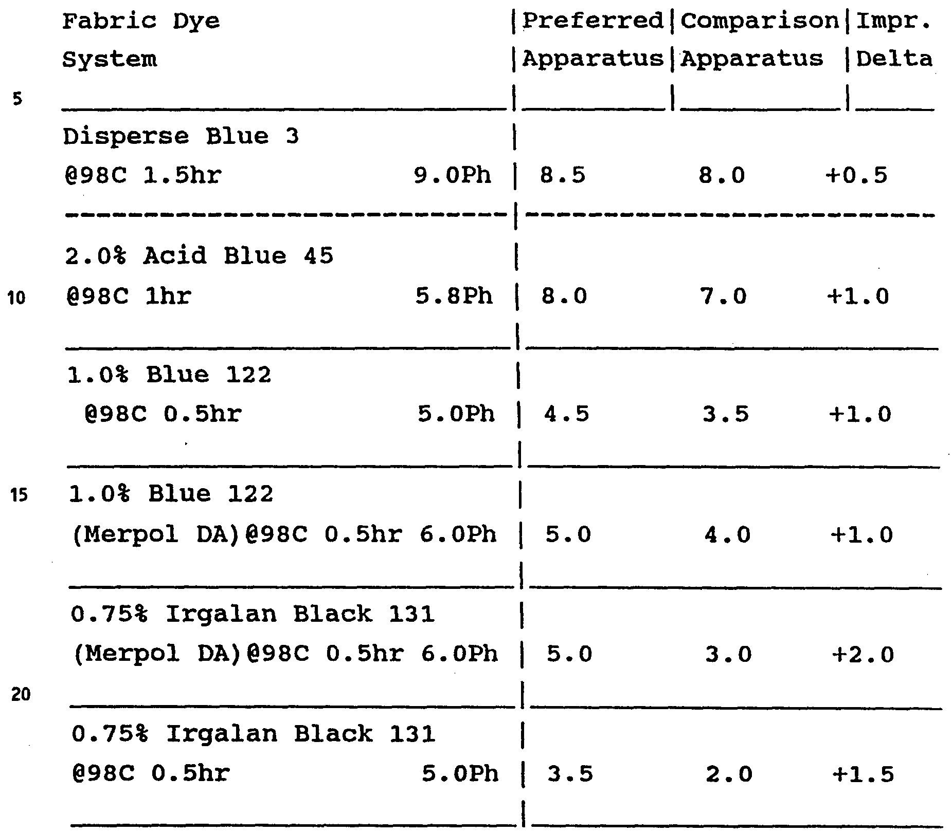
When the yarn produced in accordance with the invention is knit into plain jersey tricot fabric, the fabric lays much flatter than yarn produced using the straight rolls and visible configuration improvement is noted on the float side of the fabric with a portable light held so as to illuminate the fabric from a low angle. In spinning, the yarn stability on the preferred tension increase roll assembly is very much improved and the yarn defects detected in knitting and beaming are very much reduced. However the main improvement noted is in fabrics made from the yarns when dyed with reactive dyes, particularly large molecule reactive dyes. In Table 3 below, fabric rating results were determined using the computer generated streak rating series available from the American Association of Textile Chemists and Colorists. P.O. Box 12215, Research Triangle Park, NC 27709 with 1.0 indicating the worst streaks and 10.0 indicating no streaks. Fabrics were rated on the float side of the fabric.
u Table 3
Figure imgf000017_0001
EXAMPLE 2
In this example, apparatus for high speed spinning is illustrated in Figures 4a, 4b and 5 for use in the high speed spinning of polyester at over 5000 mpm employing a process according to the invention. Using apparatus illustrated at that speed using a pair of conventional straight rolls instead of the tension release roll system will result in a sufficient tension that packaging of the yarn would be poor.
A 34 filament capillary spinneret with 0.2286 millimeter by 0.3048 millimeter (0.009 inch by 0.012 inch) capillaries is used to high speed spin a 70 denier polyester yarn. The spun yarn is advanced to roll of tension decreasing roll assembly 215 as depicted in Figures 4a and 4b except that there are six roll contact areas incrementally decreasing in diameter instead of 4. Contact area 216 of the assembly 215 has an initial diameter of 15.24 centimeters (6.0 inches) and then contacts roll contact area 218 and back to contact area 220 and so on through the six decreasing diameters as indicated in Table 4 below. Cant and skew angles are held to a minimum to improve threadline stability. The surface of the driven rolls are low friction. A conventional spin finish is applied to the spun filaments 4 by applicator 6. The tension values and the coefficient of friction reported in table 4 are based on data from a process using conventional straight rolls.
Table 4
Wrap|Total|Creep|% of | Tens. | Tens. | Empirical |Dia. No. |wrap |wrap |angle| high | Low | coefficient!deer.
ON |rad. | rad. |in | | | friction |to
DIA | A(n)|B(n) |creep| T(H) | T(L) | u |next.
Figure imgf000018_0001
While preferred embodiments have been shown and described in the foregoing detailed description, it will be understood that the invention is capable of numerous modifications, rearrangements and substitution of parts without departing from the spirit of the invention as set forth in the appended claims.

Claims

CLAIMS :
1. In a thermoplastic polymer yarn drawing process in which a yarn is drawn by advancing the yarn into a draw zone between feed roll means and at least one subsequent draw roll means rotating at a higher speed than said feed roll means, said yarn undergoing a tension increase of at least 30% as said yarn is advanced by said feed roll means into said draw zone, the improvement which comprises: spirally advancing said yarn, before said yarn enters said draw zone, along a pair of spaced- apart rolls with said yarn contacting said rolls in successive wraps, at least one of said rolls being driven and having a diameter which increases as said yarn proceeds between at least two of said wraps on said pair of rolls, said wraps each contacting said surface of said driven roll over a roll contact area to each define a total wrap angle for said wrap, the number of said wraps on said roll and said diameter of o said driven rolls at each of said contact areas being selected to increase said tension while preventing a wrap angle in creep for any one of said wraps from being greater than about 90% of said total wrap angle for said wrap and while preventing the tension in any 5 one of said wraps from being greater than about 90% of the yarn draw tension of said yarn.
2. The process of claim 1 wherein the number of said wraps on said roll and said diameter of said driven roll at each of said contact areas being 0 selected to increase said tension while preventing a wrap angle in creep for any one of said wraps from being greater than about 80% of said total wrap angle.
3. The process of claim 1 wherein both of said rolls of said pair are driven and both have a 5 diameter which increases as said yarn proceeds between at least two of said wraps.
4. The process of claim 3 wherein the diameter of each of said driven rolls is such that the tension increases in increments over each of said wraps.
5. The process of claim 1 wherein said pair of rolls is said feed rolls means.
6. The process of claim 1 wherein said yarn is an aliphatic polyamide yarn.
7. In a process in which a thermoplastic polymer yarn is extruded through and withdrawn from a spinneret and subsequently wound up, the tension on said yarn in at least one step of said process being decreased by a tension release zone tension decrease of at least about 20% in a tension release zone prior to windup, the improvement which comprises: spirally advancing said yarn, before said yarn enters said tension release zone, along a pair of spaced-apart rolls with said yarn contacting said rolls in successive wraps, at least one of said rolls being driven and having a diameter which decreases as said yarn proceeds between at least two of said wraps on said pair of rolls, said wraps each contacting said surface of said driven roll over a roll contact area to each define a total wrap angle for said wrap, the number of said wraps on said roll and said diameter of said driven roll at each of said contact areas being selected to decrease said tension while preventing a wrap angle in creep for any one of said wraps from being greater than about 90% of said total wrap angle for said wrap.
8. The process of claim 7 wherein said tension release zone tension decrease is greater than about 30%.
9. The process of claim 7 wherein said tension release zone tension decrease occurs after said yarn leaves a draw zone in which said yarn is drawn by advancing the yarn between feed roll means and at least one subsequent draw roll means rotating at a higher speed than said feed roll means.
10. The process of claim 9 wherein said pair of rolls is said draw roll means.
11. The process of claim 7 wherein said yarn is a polyester yarn and said yarn is withdrawn from the spinneret at a withdrawal speed of at least about 3000 mpm.
12. The process of claim 7 wherein said yarn is an aliphatic polyamide yarn and said yarn is withdrawn from the spinneret at a withdrawal speed of at least about 4000 mpm.
13. The process of claim 7 wherein said number of wraps and the diameter of said rolls at said contact areas are selected to decrease said tension while preventing a wrap angle in creep for any one of said wraps from being greater than about 80% of said total wrap angle for said wrap.
14. The process of claim 7 wherein both of said rolls of said pair are driven and both have a diameter which decreases as said yarn proceeds between at least two of said wraps.
15. The process of claim 14 wherein the diameter of both of said driven rolls is such that the tension decreases in increments over each of said contact areas.
PCT/US1992/004643 1990-12-18 1992-06-09 Process for the production of uniform yarns via reduced tension-induced slippage WO1993025734A1 (en)

Priority Applications (5)

Application Number Priority Date Filing Date Title
AU21873/92A AU669115B2 (en) 1990-12-18 1992-06-09 Process for the production of uniform yarns via reduced tension-induced slippage
EP92913532A EP0644957B1 (en) 1990-12-18 1992-06-09 Process for the production of uniform yarns via reduced tension-induced slippage
BR9207146A BR9207146A (en) 1990-12-18 1992-06-09 Production process of thermoplastic polymer yarns
DE69217394T DE69217394T2 (en) 1990-12-18 1992-06-09 METHOD FOR PRODUCING REGULAR YARNS BY REDUCING TENSION-INDUCED SLIDING
ES92913532T ES2097915T3 (en) 1990-12-18 1992-06-09 PROCEDURE FOR THE PRODUCTION OF UNIFORM THREADS BY REDUCING TENSION-INDUCED SLIDING.

Applications Claiming Priority (1)

Application Number Priority Date Filing Date Title
US07/629,756 US5136763A (en) 1990-12-18 1990-12-18 Process for the production of uniform yarns via reduced tension-induced slippage

Publications (1)

Publication Number Publication Date
WO1993025734A1 true WO1993025734A1 (en) 1993-12-23

Family

ID=24524359

Family Applications (1)

Application Number Title Priority Date Filing Date
PCT/US1992/004643 WO1993025734A1 (en) 1990-12-18 1992-06-09 Process for the production of uniform yarns via reduced tension-induced slippage

Country Status (7)

Country Link
US (1) US5136763A (en)
EP (1) EP0644957B1 (en)
AU (1) AU669115B2 (en)
BR (1) BR9207146A (en)
DE (1) DE69217394T2 (en)
ES (1) ES2097915T3 (en)
WO (1) WO1993025734A1 (en)

Cited By (3)

* Cited by examiner, † Cited by third party
Publication number Priority date Publication date Assignee Title
WO1998023797A1 (en) * 1996-11-27 1998-06-04 E.I. Du Pont De Nemours And Company Spinning machine and conversion process
DE19847744A1 (en) * 1998-10-16 2000-04-20 Leuze Textil Gmbh & Co Preparation of filament yarn for producing core yarn comprises continuous mechanical stretching and relaxing to low tension followed by core yarn spinning
US6375882B1 (en) 1996-11-27 2002-04-23 E. I. Du Pont De Nemours And Company Spinning machine and conversion process

Families Citing this family (8)

* Cited by examiner, † Cited by third party
Publication number Priority date Publication date Assignee Title
US5136763A (en) * 1990-12-18 1992-08-11 E. I. Du Pont De Nemours And Company Process for the production of uniform yarns via reduced tension-induced slippage
DE4215015A1 (en) * 1992-05-12 1993-11-18 Amann & Soehne Stretching process
CH692704A5 (en) * 1997-10-08 2002-09-30 Rieter Ag Maschf Spinnstreckspul machine.
DE19909073B4 (en) * 1998-03-05 2008-03-13 Oerlikon Textile Gmbh & Co. Kg Apparatus and method for drawing a synthetic thread
DE10343462A1 (en) * 2002-10-11 2004-04-22 Saurer Gmbh & Co. Kg Synthetic multifilament hotmelt thread spinning and winding process has galette with stepped mantle and thread guide grooves creating speed differential between two galettes
FR2871454B1 (en) * 2004-06-09 2006-10-06 Rieter Textile Machinery Fr DEVICE FOR TENSIONING A FILTERY MATERIAL, IN PARTICULAR A TEXTILE YARN
EP1961686B1 (en) 2007-02-20 2016-09-14 Iro Ab Yarn tension monitoring and setting system
WO2020041838A1 (en) * 2018-08-31 2020-03-05 The University Of Sydney Fibre forming process

Citations (6)

* Cited by examiner, † Cited by third party
Publication number Priority date Publication date Assignee Title
US4042662A (en) * 1970-05-13 1977-08-16 Akzona Incorporated Continuous melt spinning and drawing of nylon 6 yarn, while reducing the liveliness of the yarn
JPS548767B2 (en) * 1974-05-08 1979-04-18
JPS5947726B2 (en) * 1977-05-16 1984-11-21 帝人株式会社 Polyester fiber manufacturing method
US4778118A (en) * 1987-08-10 1988-10-18 Belmont Textile Machinery Co., Inc. Yarn tension control apparatus and method
WO1989010831A1 (en) * 1988-05-09 1989-11-16 Sussman Martin V Improved method and apparatus for incrementally drawing fibers
US5136763A (en) * 1990-12-18 1992-08-11 E. I. Du Pont De Nemours And Company Process for the production of uniform yarns via reduced tension-induced slippage

Family Cites Families (18)

* Cited by examiner, † Cited by third party
Publication number Priority date Publication date Assignee Title
DE628569C (en) * 1932-05-31 1936-04-07 Steckborn Kunstseide A G Device for the production of viscose rayon with stretching
GB509854A (en) * 1939-02-24 1939-07-24 Lustrafil Ltd Improvements in or relating to the treatment of filaments, threads or yarns
US2289232A (en) * 1939-07-14 1942-07-07 Du Pont Method and apparatus for producing filamentary structures
US2413073A (en) * 1945-07-26 1946-12-24 Du Pont Stretching rolls
US2728973A (en) * 1950-08-11 1956-01-03 Inventa Ag Device for stretching synthetic silk
BE514447A (en) * 1951-09-27
US2736944A (en) * 1953-09-02 1956-03-06 John Bright & Brothers Ltd Means for stretching cords, yarns and the like
FR1236259A (en) * 1959-09-17 1960-07-15 Toyo Koatsu Ind Inc Synthetic fiber draw point adjustment method
GB934383A (en) * 1961-04-18 1963-08-21 Ici Ltd Textile drawing and drafting machines
GB907904A (en) * 1961-04-20 1962-10-10 Whitin Machine Works Apparatus for stretching yarn
DE1435467A1 (en) * 1964-12-31 1968-11-21 Hoechst Ag Process for drawing threads made of synthetic, linear polyesters
US3452130A (en) * 1967-02-02 1969-06-24 Du Pont Jet initiated drawing process
NL164909C (en) * 1968-10-08 1981-02-16 Algemene Kunstzijde Unie Nv METHOD AND APPARATUS FOR AT LEAST TWO STEP STRETCHING OF A THERMOPLASTIC PRODUCT AND THE PRODUCT PRODUCED BY THE METHOD
NL7000713A (en) * 1969-12-04 1971-06-08
GB1305758A (en) * 1970-09-03 1973-02-07
US3978192A (en) * 1971-09-23 1976-08-31 Sussman Martin V Method of drawing fibers using a microterraced drawing surface
US3892020A (en) * 1973-12-14 1975-07-01 Du Pont Preparing a textured yarn package, for dyeing
JPS6065142A (en) * 1983-09-14 1985-04-13 村田機械株式会社 Draw roller in texture card producing apparatus

Patent Citations (6)

* Cited by examiner, † Cited by third party
Publication number Priority date Publication date Assignee Title
US4042662A (en) * 1970-05-13 1977-08-16 Akzona Incorporated Continuous melt spinning and drawing of nylon 6 yarn, while reducing the liveliness of the yarn
JPS548767B2 (en) * 1974-05-08 1979-04-18
JPS5947726B2 (en) * 1977-05-16 1984-11-21 帝人株式会社 Polyester fiber manufacturing method
US4778118A (en) * 1987-08-10 1988-10-18 Belmont Textile Machinery Co., Inc. Yarn tension control apparatus and method
WO1989010831A1 (en) * 1988-05-09 1989-11-16 Sussman Martin V Improved method and apparatus for incrementally drawing fibers
US5136763A (en) * 1990-12-18 1992-08-11 E. I. Du Pont De Nemours And Company Process for the production of uniform yarns via reduced tension-induced slippage

Cited By (4)

* Cited by examiner, † Cited by third party
Publication number Priority date Publication date Assignee Title
WO1998023797A1 (en) * 1996-11-27 1998-06-04 E.I. Du Pont De Nemours And Company Spinning machine and conversion process
US6375882B1 (en) 1996-11-27 2002-04-23 E. I. Du Pont De Nemours And Company Spinning machine and conversion process
DE19847744A1 (en) * 1998-10-16 2000-04-20 Leuze Textil Gmbh & Co Preparation of filament yarn for producing core yarn comprises continuous mechanical stretching and relaxing to low tension followed by core yarn spinning
DE19847744B4 (en) * 1998-10-16 2004-04-22 Leuze Textil Gmbh + Co Process for producing core yarns and / or threads from such yarns and device for carrying out the process

Also Published As

Publication number Publication date
AU2187392A (en) 1994-01-04
AU669115B2 (en) 1996-05-30
EP0644957A1 (en) 1995-03-29
EP0644957B1 (en) 1997-02-05
BR9207146A (en) 1995-09-12
DE69217394D1 (en) 1997-03-20
ES2097915T3 (en) 1997-04-16
DE69217394T2 (en) 1997-07-10
US5136763A (en) 1992-08-11

Similar Documents

Publication Publication Date Title
US4049763A (en) Process for producing a highly oriented polyester undrawn yarn
US6673443B2 (en) Polyester conjugate fiber pirn and method for producing same
US5136763A (en) Process for the production of uniform yarns via reduced tension-induced slippage
US4390685A (en) Polyester fiber and process for producing same
US7785709B2 (en) Spinning poly(trimethylene terephthalate) yarns
US4247505A (en) Melt spinning of polymers
US6682815B2 (en) Stretched yarn pirn
US3770866A (en) Drawing polyester filaments using as a snubing means a heated roller driven at the feed rate speed
CN1076409C (en) Process for producing a high-strength, high-shrinkage polyamide 66 filament yarn
US5087401A (en) Process for preparing polyester filamentary material
US4019312A (en) Method of combining synthetic yarns
US3665696A (en) Yarn packaging
JPS60209013A (en) Preparation of polyester yarn
US4043108A (en) Process
JP3130640B2 (en) Method for producing polyester fiber
JPH08199424A (en) Polyester monofilament package
US6115893A (en) Process and device for producing industrial polyester yarn
JPS60128166A (en) Method of producing polyamide fiber
JPH0735606B2 (en) Method for manufacturing polyester thermal shrinkage difference mixed yarn
JP2895530B2 (en) Method for producing large fine filament yarn
KR100315150B1 (en) Preparation and apparatus of polyester filber
JPS60128167A (en) Method of producing polyamide fiber
JP2976787B2 (en) Method for producing latent bulky polyester yarn
JPH0336165A (en) Continuous drawing single-filament-yarn separating method and device thereof
JPH0633334A (en) Drawing of monofilament for screen gauze

Legal Events

Date Code Title Description
AK Designated states

Kind code of ref document: A1

Designated state(s): AU BR CA

AL Designated countries for regional patents

Kind code of ref document: A1

Designated state(s): AT BE CH DE DK ES FR GB GR IT LU MC NL SE

DFPE Request for preliminary examination filed prior to expiration of 19th month from priority date (pct application filed before 20040101)
121 Ep: the epo has been informed by wipo that ep was designated in this application
WWE Wipo information: entry into national phase

Ref document number: 1992913532

Country of ref document: EP

WWP Wipo information: published in national office

Ref document number: 1992913532

Country of ref document: EP

NENP Non-entry into the national phase

Ref country code: CA

WWG Wipo information: grant in national office

Ref document number: 1992913532

Country of ref document: EP