WO1994006349A1 - Endocardial mapping system - Google Patents
Endocardial mapping system Download PDFInfo
- Publication number
- WO1994006349A1 WO1994006349A1 PCT/US1993/009015 US9309015W WO9406349A1 WO 1994006349 A1 WO1994006349 A1 WO 1994006349A1 US 9309015 W US9309015 W US 9309015W WO 9406349 A1 WO9406349 A1 WO 9406349A1
- Authority
- WO
- WIPO (PCT)
- Prior art keywords
- electrode
- array
- heart
- lead body
- electrodes
- Prior art date
Links
Classifications
-
- A—HUMAN NECESSITIES
- A61—MEDICAL OR VETERINARY SCIENCE; HYGIENE
- A61B—DIAGNOSIS; SURGERY; IDENTIFICATION
- A61B5/00—Measuring for diagnostic purposes; Identification of persons
- A61B5/68—Arrangements of detecting, measuring or recording means, e.g. sensors, in relation to patient
- A61B5/6846—Arrangements of detecting, measuring or recording means, e.g. sensors, in relation to patient specially adapted to be brought in contact with an internal body part, i.e. invasive
- A61B5/6847—Arrangements of detecting, measuring or recording means, e.g. sensors, in relation to patient specially adapted to be brought in contact with an internal body part, i.e. invasive mounted on an invasive device
- A61B5/6852—Catheters
- A61B5/6853—Catheters with a balloon
-
- A—HUMAN NECESSITIES
- A61—MEDICAL OR VETERINARY SCIENCE; HYGIENE
- A61B—DIAGNOSIS; SURGERY; IDENTIFICATION
- A61B18/00—Surgical instruments, devices or methods for transferring non-mechanical forms of energy to or from the body
- A61B18/04—Surgical instruments, devices or methods for transferring non-mechanical forms of energy to or from the body by heating
- A61B18/12—Surgical instruments, devices or methods for transferring non-mechanical forms of energy to or from the body by heating by passing a current through the tissue to be heated, e.g. high-frequency current
- A61B18/14—Probes or electrodes therefor
- A61B18/1492—Probes or electrodes therefor having a flexible, catheter-like structure, e.g. for heart ablation
-
- A—HUMAN NECESSITIES
- A61—MEDICAL OR VETERINARY SCIENCE; HYGIENE
- A61B—DIAGNOSIS; SURGERY; IDENTIFICATION
- A61B5/00—Measuring for diagnostic purposes; Identification of persons
- A61B5/05—Detecting, measuring or recording for diagnosis by means of electric currents or magnetic fields; Measuring using microwaves or radio waves
- A61B5/053—Measuring electrical impedance or conductance of a portion of the body
- A61B5/0538—Measuring electrical impedance or conductance of a portion of the body invasively, e.g. using a catheter
-
- A—HUMAN NECESSITIES
- A61—MEDICAL OR VETERINARY SCIENCE; HYGIENE
- A61B—DIAGNOSIS; SURGERY; IDENTIFICATION
- A61B5/00—Measuring for diagnostic purposes; Identification of persons
- A61B5/103—Detecting, measuring or recording devices for testing the shape, pattern, colour, size or movement of the body or parts thereof, for diagnostic purposes
- A61B5/107—Measuring physical dimensions, e.g. size of the entire body or parts thereof
- A61B5/1076—Measuring physical dimensions, e.g. size of the entire body or parts thereof for measuring dimensions inside body cavities, e.g. using catheters
-
- A—HUMAN NECESSITIES
- A61—MEDICAL OR VETERINARY SCIENCE; HYGIENE
- A61B—DIAGNOSIS; SURGERY; IDENTIFICATION
- A61B5/00—Measuring for diagnostic purposes; Identification of persons
- A61B5/24—Detecting, measuring or recording bioelectric or biomagnetic signals of the body or parts thereof
- A61B5/25—Bioelectric electrodes therefor
- A61B5/279—Bioelectric electrodes therefor specially adapted for particular uses
- A61B5/28—Bioelectric electrodes therefor specially adapted for particular uses for electrocardiography [ECG]
- A61B5/282—Holders for multiple electrodes
-
- A—HUMAN NECESSITIES
- A61—MEDICAL OR VETERINARY SCIENCE; HYGIENE
- A61B—DIAGNOSIS; SURGERY; IDENTIFICATION
- A61B5/00—Measuring for diagnostic purposes; Identification of persons
- A61B5/24—Detecting, measuring or recording bioelectric or biomagnetic signals of the body or parts thereof
- A61B5/25—Bioelectric electrodes therefor
- A61B5/279—Bioelectric electrodes therefor specially adapted for particular uses
- A61B5/28—Bioelectric electrodes therefor specially adapted for particular uses for electrocardiography [ECG]
- A61B5/283—Invasive
- A61B5/287—Holders for multiple electrodes, e.g. electrode catheters for electrophysiological study [EPS]
-
- A—HUMAN NECESSITIES
- A61—MEDICAL OR VETERINARY SCIENCE; HYGIENE
- A61B—DIAGNOSIS; SURGERY; IDENTIFICATION
- A61B5/00—Measuring for diagnostic purposes; Identification of persons
- A61B5/68—Arrangements of detecting, measuring or recording means, e.g. sensors, in relation to patient
- A61B5/6846—Arrangements of detecting, measuring or recording means, e.g. sensors, in relation to patient specially adapted to be brought in contact with an internal body part, i.e. invasive
- A61B5/6847—Arrangements of detecting, measuring or recording means, e.g. sensors, in relation to patient specially adapted to be brought in contact with an internal body part, i.e. invasive mounted on an invasive device
- A61B5/6852—Catheters
- A61B5/6858—Catheters with a distal basket, e.g. expandable basket
-
- A—HUMAN NECESSITIES
- A61—MEDICAL OR VETERINARY SCIENCE; HYGIENE
- A61N—ELECTROTHERAPY; MAGNETOTHERAPY; RADIATION THERAPY; ULTRASOUND THERAPY
- A61N1/00—Electrotherapy; Circuits therefor
- A61N1/18—Applying electric currents by contact electrodes
- A61N1/32—Applying electric currents by contact electrodes alternating or intermittent currents
- A61N1/36—Applying electric currents by contact electrodes alternating or intermittent currents for stimulation
- A61N1/362—Heart stimulators
- A61N1/3625—External stimulators
-
- A—HUMAN NECESSITIES
- A61—MEDICAL OR VETERINARY SCIENCE; HYGIENE
- A61N—ELECTROTHERAPY; MAGNETOTHERAPY; RADIATION THERAPY; ULTRASOUND THERAPY
- A61N1/00—Electrotherapy; Circuits therefor
- A61N1/18—Applying electric currents by contact electrodes
- A61N1/32—Applying electric currents by contact electrodes alternating or intermittent currents
- A61N1/36—Applying electric currents by contact electrodes alternating or intermittent currents for stimulation
- A61N1/362—Heart stimulators
- A61N1/37—Monitoring; Protecting
- A61N1/3702—Physiological parameters
-
- A—HUMAN NECESSITIES
- A61—MEDICAL OR VETERINARY SCIENCE; HYGIENE
- A61B—DIAGNOSIS; SURGERY; IDENTIFICATION
- A61B18/00—Surgical instruments, devices or methods for transferring non-mechanical forms of energy to or from the body
- A61B18/18—Surgical instruments, devices or methods for transferring non-mechanical forms of energy to or from the body by applying electromagnetic radiation, e.g. microwaves
- A61B18/1815—Surgical instruments, devices or methods for transferring non-mechanical forms of energy to or from the body by applying electromagnetic radiation, e.g. microwaves using microwaves
-
- A—HUMAN NECESSITIES
- A61—MEDICAL OR VETERINARY SCIENCE; HYGIENE
- A61B—DIAGNOSIS; SURGERY; IDENTIFICATION
- A61B18/00—Surgical instruments, devices or methods for transferring non-mechanical forms of energy to or from the body
- A61B18/18—Surgical instruments, devices or methods for transferring non-mechanical forms of energy to or from the body by applying electromagnetic radiation, e.g. microwaves
- A61B18/20—Surgical instruments, devices or methods for transferring non-mechanical forms of energy to or from the body by applying electromagnetic radiation, e.g. microwaves using laser
- A61B18/22—Surgical instruments, devices or methods for transferring non-mechanical forms of energy to or from the body by applying electromagnetic radiation, e.g. microwaves using laser the beam being directed along or through a flexible conduit, e.g. an optical fibre; Couplings or hand-pieces therefor
- A61B18/24—Surgical instruments, devices or methods for transferring non-mechanical forms of energy to or from the body by applying electromagnetic radiation, e.g. microwaves using laser the beam being directed along or through a flexible conduit, e.g. an optical fibre; Couplings or hand-pieces therefor with a catheter
-
- A—HUMAN NECESSITIES
- A61—MEDICAL OR VETERINARY SCIENCE; HYGIENE
- A61B—DIAGNOSIS; SURGERY; IDENTIFICATION
- A61B18/00—Surgical instruments, devices or methods for transferring non-mechanical forms of energy to or from the body
- A61B2018/00053—Mechanical features of the instrument of device
- A61B2018/00214—Expandable means emitting energy, e.g. by elements carried thereon
- A61B2018/00267—Expandable means emitting energy, e.g. by elements carried thereon having a basket shaped structure
-
- A—HUMAN NECESSITIES
- A61—MEDICAL OR VETERINARY SCIENCE; HYGIENE
- A61B—DIAGNOSIS; SURGERY; IDENTIFICATION
- A61B18/00—Surgical instruments, devices or methods for transferring non-mechanical forms of energy to or from the body
- A61B2018/00636—Sensing and controlling the application of energy
- A61B2018/00773—Sensed parameters
- A61B2018/00839—Bioelectrical parameters, e.g. ECG, EEG
-
- A—HUMAN NECESSITIES
- A61—MEDICAL OR VETERINARY SCIENCE; HYGIENE
- A61B—DIAGNOSIS; SURGERY; IDENTIFICATION
- A61B2560/00—Constructional details of operational features of apparatus; Accessories for medical measuring apparatus
- A61B2560/04—Constructional details of apparatus
- A61B2560/0443—Modular apparatus
- A61B2560/045—Modular apparatus with a separable interface unit, e.g. for communication
-
- A—HUMAN NECESSITIES
- A61—MEDICAL OR VETERINARY SCIENCE; HYGIENE
- A61B—DIAGNOSIS; SURGERY; IDENTIFICATION
- A61B2562/00—Details of sensors; Constructional details of sensor housings or probes; Accessories for sensors
- A61B2562/04—Arrangements of multiple sensors of the same type
- A61B2562/043—Arrangements of multiple sensors of the same type in a linear array
-
- A—HUMAN NECESSITIES
- A61—MEDICAL OR VETERINARY SCIENCE; HYGIENE
- A61B—DIAGNOSIS; SURGERY; IDENTIFICATION
- A61B2562/00—Details of sensors; Constructional details of sensor housings or probes; Accessories for sensors
- A61B2562/04—Arrangements of multiple sensors of the same type
- A61B2562/046—Arrangements of multiple sensors of the same type in a matrix array
-
- A—HUMAN NECESSITIES
- A61—MEDICAL OR VETERINARY SCIENCE; HYGIENE
- A61B—DIAGNOSIS; SURGERY; IDENTIFICATION
- A61B5/00—Measuring for diagnostic purposes; Identification of persons
- A61B5/24—Detecting, measuring or recording bioelectric or biomagnetic signals of the body or parts thereof
- A61B5/30—Input circuits therefor
-
- Y—GENERAL TAGGING OF NEW TECHNOLOGICAL DEVELOPMENTS; GENERAL TAGGING OF CROSS-SECTIONAL TECHNOLOGIES SPANNING OVER SEVERAL SECTIONS OF THE IPC; TECHNICAL SUBJECTS COVERED BY FORMER USPC CROSS-REFERENCE ART COLLECTIONS [XRACs] AND DIGESTS
- Y10—TECHNICAL SUBJECTS COVERED BY FORMER USPC
- Y10T—TECHNICAL SUBJECTS COVERED BY FORMER US CLASSIFICATION
- Y10T29/00—Metal working
- Y10T29/49—Method of mechanical manufacture
- Y10T29/49002—Electrical device making
- Y10T29/49117—Conductor or circuit manufacturing
Definitions
- the invention discloses the apparatus and technique for forming a three-dimensional electrical map of the interior of a heart chamber, and a related technique for forming a two-dimensional subsurface map at a particular location in the endocardial wall.
- mapping technique involves a sequence of electrical measurements taken from mobile electrodes inserted into the heart chamber and placed in contact with the surface of the heart.
- An alternative mapping technique takes
- electrically active tissue is required by most systems in the prior art in order to obtain well conditioned electrical signals.
- An exception is a non-contact approach with spot electrodes. These spot electrodes spatially average the electrical signal through their conical view of the blood media. This approach
- the present invention provides a method for producing a high-resolution, three-dimensional map of electrical activity of the inside surface of a heart chamber.
- the invention uses a specialized catheter system to obtain the information necessary to generate such a map.
- the invention provides a system and method which permits the location of catheter electrodes to be visualized in the three-dimensional map.
- the invention may also be used to provide a two- dimensional map of electrical potential at or below the myocardial tissue surface.
- Figure 1 is a schematic view of the system.
- Figure 2 is a view of the catheter assembly placed in an endocardial cavity.
- Figure 3 is a schematic view of the catheter assembly.
- Figure 4 is a view of the mapping catheter with the deformable lead body in the collapsed position.
- Figure 5 is a view of the mapping catheter with the deformable lead body in the expanded position.
- Figure 6 is a view of the reference catheter.
- Figure 7 is a schematic view representing the display of the three-dimensional map.
- Figure 8 is a side view of an alternate reference catheter.
- Figure 9 is a side view of an alternate reference catheter.
- Figure 10 is a perspective view of an alternate distal tip.
- Figure 11 is a schematic view representing the display of the subsurface two-dimensional map.
- Figure 12 is a schematic flow chart of the steps in the method. Detailed Disclosure
- the system of the present invention is used for mapping the electrical activity of the interior surface of a heart chamber 80.
- the mapping catheter assembly 14 includes a flexible lead body 72 connected to a deformable distal lead body 74.
- the deformable distal lead body 74 can be formed into a stable space filling geometric shape after introduction into the heart cavity 80.
- This deformable distal lead body 74 includes an electrode array 19 defining a number of electrode sites.
- the mapping catheter assembly 14 also includes a reference electrode preferably placed on a reference catheter 16 which passes through a central lumen 82 formed in the flexible lead body 72 and the distal lead body 74.
- the reference catheter assembly 16 has a distal tip electrode assembly 24 which may be used to probe the heart wall.
- This distal contact electrode assembly 24 provides a surface electrical reference for calibration.
- the physical length of the reference catheter 16 taken with the position of the electrode array 19 together provide a reference which may be used to calibrate the electrode array 19.
- the reference catheter 16 also stabilizes the position of the
- catheter assembly which can be readily positioned within the heart and used to acquire highly accurate
- the mapping catheter assembly 14 is coupled to interface apparatus 22 which contains a signal generator 32, and voltage acquisition apparatus 30.
- the signal generator 32 is used to measure the volumetric shape of the heart chamber through impedance plethysmography. This signal generator is also used to determine the position of the reference electrode within the heart chamber. Other techniques for characterizing the shape of the heart chamber may be substituted.
- the signals from all the electrode sites on the electrode array 19 are presented to the voltage
- acquisition apparatus 30 to derive a three-dimensional, instantaneous high resolution map of the electrical activity of the entire heart chamber volume.
- This map is calibrated by the use of a surface electrode 24. The calibration is both electrical and dimensional.
- the two-dimensional map is a slice of the heart wall and represents the subsurface electrical activity in the heart wall itself.
- the true three-dimensional map also avoids the problem of spatial averaging and generates an instantaneous, high resolution map of the electrical activity of the entire volume of the heart chamber and the endocardial surface. This three-dimensional map is an order of magnitude more accurate and precise than previously obtained interpolation maps. The two-dimensional map of the intramural slice is unavailable using prior techniques.
- Figure 1 shows the mapping system 10 coupled to a patient's heart 12.
- the mapping catheter assembly 14 is inserted into a heart chamber and the reference
- electrode 24 touches the endocardial surface 18.
- the preferred array catheter 20 carries at least twenty-four individual electrode sites which are coupled to the interface apparatus 22.
- the preferred reference catheter 16 is a coaxial extension of the array catheter 20.
- This reference catheter 16 includes a surface electrode site 24 and a subsurface electrode site 26 both of which are coupled to the interface apparatus 22. It should be understood that the electrode site 24 can be located directly on the array catheter.
- the array catheter 20 may be expanded into a known geometric shape, preferably spherical. Resolution is enhanced by the use of larger sized spherical shapes.
- a balloon 77 or the like should be incorporated under the electrode array 19 to exclude blood from the interior of the electrode array 19. The spherical shape and exclusion of blood are not required for operability but they materially reduce the complexity of the calculations required to generate the map displays.
- reference catheter 16 serves several purposes. First they stabilize and maintain the array 19 at a known distance from a reference point on the endocardial surface 18 for calibration of the shape and volume calculations. Secondly, the surface electrode 24 is used to calibrate the electrical activity measurements of the endocardial surface 18 provided by the electrode array 19.
- the interface apparatus 22 includes a switching assembly 28 which is a multiplexor to sequentially couple the various electrode sites to the voltage acquisition apparatus 30, and the signal generator apparatus 32. These devices are under the control of a computer 34.
- the voltage acquisition apparatus 30 is preferably a 12 bit A to D convertor.
- a signal ⁇ generator 32 is also supplied to generate low current pulses for determining the volume and shape of the endocardial chamber using impedance plethysmography, and for determining the location of the reference catheter .
- the computer 34 is preferably of the "workstation” class to provide sufficient processing power to operate in essentially real time. This computer operates under the control of software set forth in the flow charts of Figures 12A and 12B. Catheter Description
- Figure 2 shows a portion of the mapping catheter assembly 14 placed into a heart chamber 80.
- the mapping catheter assembly 14 includes a reference catheter 16 and an array catheter 20.
- the array catheter 20 has been expanded through the use of a stylet 92 to place the electrode array 19 into a stable and
- the reference catheter 16 has been passed through the lumen 82 of the array catheter 20 to place a distal tip electrode assembly 24 into position against an endocardial surface.
- the reference catheter 16 provides a mechanical location reference for the position of the electrode array 19, and the tip electrode assembly 24 provides an electrical potential reference at or in the heart wall for the mapping process.
- the principle objective of the preferred form of the catheter system is to reliably place a known collection of electrode sites away from the endocardial surface, and one or more electrode sites into contact with the endocardium.
- the array catheter is an
- the array catheter itself can be designed to mechanically position one or more electrode sites on the endocardial surface.
- the reference catheter is a preferred
- structure for carrying one or more electrode sites may be used to place these electrode sites into direct contact with the endocardial surface.
- the reference catheter could be replaced with a fixed extension of the array catheter and used to push a segment of the array onto the endocardial surface.
- the geometric shape of the spherical array maintains the other electrodes out of contact with the endocardial surface.
- Figure 3 shows the preferred construction of the mapping catheter assembly 14 in exaggerated scale to clarify details of construction.
- the array catheter 20 includes a flexible lead body 72 coupled to a deformable lead body 74.
- the deformable lead body 74 is preferably a braid 75 of insulated wires, several of which are shown as wire 93, wire 94, wire 95 and wire 96.
- An individual wire such as 93 may be traced in the figure from the electrical connection 79 at the proximal end 81 of the flexible lead body 72 through the flexible lead body 72 to the distal braid ring 83 located on the deformable lead body 74.
- the insulation has been selectively removed from this wire 93 to form a
- Each of the several wires in the braid 75 may potentially be used to form an electrode site.
- Preferably all of the typically twenty- four to one-hundred-twenty-eight wires in the braid 75 are used to form electrode sites.
- Wires not used as electrode sites provide mechanical support for the electrode array 19.
- the electrode sites will be located equidistant from a center defined at the center of the spherical array. Other geometrical shapes are usable including ellipsoidal and the like.
- the proximal connector 79 can have a suitable electrical connection for the distal tip electrode assembly 24 of the reference catheter 16 or the reference catheter 16 can use a separate connector.
- the distance 90 between the electrode array 19 and the distal tip assembly 24 electrode can preferentially be varied by sliding the reference catheter through the lumen 82, as shown by motion arrow 85. This distance 90 may be "read" at the proximal end 81 by noting the relative position of the end of the lead body 72 and the proximal end of the reference catheter 16.
- Figure 4 is a view of the mapping catheter with the deformable lead body 74 in the collapsed position.
- Figure 5 shows that the wire stylet 92 is attached to the distal braid ring 83 and positioned in the lumen 82. Traction applied to the distal braid ring 83 by relative motion of the stylet 92 with respect to the lead body 72 causes the braid 75 to change shape. In general, traction causes the braid 75 to move from a generally cylindrical form seen in Figure 4 to a
- the preferred technique is to provide a stylet 92 which can be used to pull the braid 75 which will deploy the electrode array 19.
- other techniques may be used as well including an optional balloon 77 shown as in Figure 3 , which could be inflated under the electrode array 19 thereby causing the spherical
- Modification of the braid 75 can be used to control the final shape of the array 19.
- an asymmetrical braid pattern using differing diameter wires within the braid can be used to control the final shape of the array 19.
- the most important property of the geometric shape is that it spaces the electrode sites relatively far apart and that the shape be predictable with a high degree of accuracy.
- Figure 6 shows a first embodiment of the reference catheter 16 where the distal electrode assembly 24 is blunt and may be used to make a surface measurement against the endocardial surface.
- the wire 97 ( Figure 2) communicates to the distal tip electrode and this wire may be terminated in the connector 79.
- FIG 8 shows an alternate reference catheter 98 which is preferred if both surface and/or subsurface measurements of the potential proximate the endocardial surface are desired.
- This catheter 98 includes both a reference electrode 24 and an extendable intramural electrode body 100.
- Figure 9 illustrates the preferred use of an intramural electrode stylet 101 to retract the sharp intramural electrode body 100 into the reference catheter lead body 102. Motion of the intramural electrode body 100 into the lead body 102 is shown by arrow 103.
- Figure 10 shows the location of the intramural electrode site 26 on the electrode body 100. It is desirable to use a relatively small electrode site to permit localization of the intramural electrical activity.
- the array catheter 20 may be made by any of a variety of techniques.
- the braid 75 of insulated wires 93,94,95,96 can be encapsulated into a plastic material to form the flexible lead body 72.
- This plastic material can be any of various biocompatible compounds with polyurethane being preferred.
- the encapsulation material for the flexible lead body 72 is selected in part for its ability to be selectively removed to expose the
- insulated braid 75 to form the deformable lead body 74.
- the use of a braid 75 rather than a spiral wrap, axial wrap, or other configuration inherently strengthens and supports the electrodes due to the interlocking nature of the braid.
- This interlocking braid 75 also insures that, as the electrode array 19 deploys, it does so with predictable dimensional control.
- This braid 75
- structure also supports the array catheter 20 and provides for the structural integrity of the array catheter 20 where the encapsulating material has been removed.
- the encapsulating material can be removed by known techniques. In a preferred embodiment this removal is accomplished by mechanical removal of the encapsulating material by grinding or the like. It is also possible to remove the material with a solvent. If the encapsulating material is polyurethane, tetrahydrofuran or cyclohexanone can be used as a solvent. In some embodiments the encapsulating material is not removed from the extreme distal tip to provide enhanced mechanical integrity forming a distal braid ring 83.
- the electrodes sites can be formed by removing the insulation over the conductor in selected areas. Known techniques would involve
- the electrode site can be created by removing insulation using standard means or by applying a higher voltage (eg. 5 KV) to break through the
- the illustrative method may be partitioned into nine steps as shown in Figure 12.
- the partitioning of the step-wise sequence is done as an aid to explaining the invention and other equivalent partitioning can be readily substituted without departing from the scope of the invention.
- the process begins.
- the illustrative process assumes that the electrode array assumes a known spherical shape within the heart chamber, and that there are at least twenty-four electrodes on the electrode array 19.
- This preferred method can be readily modified to accommodate unknown and non-reproducible, non- spherical shaped arrays.
- the location of each of these electrode sites on the array surface is known from the mechanical configuration of the displayed array.
- a method of determining the location of the electrode array 19 and the location of the heart chamber walls must be available. This geometry measurement (options include ultrasound or impedance plethysmography) is performed in step 41.
- reference catheter 16 is extended to the chamber wall 18 then its length can be used to calibrate the geometry measurements since the calculated distance can be compared to the reference catheter length.
- the geometry calculations are forced to converge on the known spacing represented by the physical dimensions of the catheters.
- reference electrode 24 is positioned on array catheter 20 and therefore its position would be known.
- step 42 the signals from all the electrode sites in the electrode array 19 are sampled by the A to D converter in the voltage acquisition apparatus 30.
- step 43 the known locations of all the electrodes on the
- Electrode array 19 and the measured potentials at each electrode are used to create the intermediate parameters of the three-dimensional electrical activity map.
- This step uses field theory calculations presented in greater detail below.
- the components which are created in this step ( ⁇ lm ) are stored in a digital file for later use in following steps.
- the question is asked whether the reference catheter 16 is in a calibrating position. In the calibrating position, the reference catheter 16 projects directly out of the array catheter 20
- step 45, 46 or 47 establishing a length from the electrode array 19 which is a known distance from the wall 18 of the heart chamber. This calibration position may be confirmed using fluoroscopy. If the catheter is not in position then the process moves to step 45, 46 or 47.
- step 44 the exact position of the reference catheter 16 is determined using the distance and orientation data from step 41.
- the available information includes position in space of the reference catheter 16 on the chamber wall 18 and the intermediate electrical activity map parameters of the three-dimensional map.
- the expected electrical activity at the reference catheter surface electrode site 24 is determined.
- the actual potential at this site 24 is measured from the reference catheter by the A to D converter in the voltage acquisition apparatus 30.
- a scale factor is adjusted which modifies the map calculations to achieve calibrated results. This adjustment factor is used in all subsequent calculations of electrical activity.
- the system polls the user to display a three-dimensional map. If such a map is desired then a method of displaying the electrical activity is first determined. Second an area, or volume is defined for which the electrical activity is to be viewed. Third a level of resolution is defined for this view of the electrical activity. Finally the electrical activity at all of the points defined by the display option, volume and resolution are computed using the field theory calculations and the adjustment factor mentioned above. These calculated values are then used to display the data on computer 34.
- Figure 7 is a representative display 71 of the output of process 47.
- the heart is displayed as a wire grid 36.
- the iso-potential map for example is overlaid on the wire grid 36 and several iso-potential lines such as iso-potential or isochrone line 38 are shown on the drawing.
- the color of the wire grid 36 and the iso-potential or isochrone lines will be different to aid interpretation.
- the potentials may preferably be presented by a
- mapping catheter assembly will not be shown.
- step 45 a subthreshold pulse is supplied to the surface electrode 24 of the reference catheter 16 by the signal generator 32.
- the voltages are measured at all of the electrode sites on the electrode array 19 by the voltage acquisition apparatus 30.
- One problem in locating the position of the subthreshold pulse is that other electrical activity may render it difficult to detect.
- step 55 starts by subtracting the electrical activity which was just measured in step 44 from the measurements in step 54.
- the location of the tip of the reference catheter 16 i.e. surface electrode 24
- step 45 is found by first performing the same field theory calculations of step 45 on this derived electrode data.
- four positions in space are defined which are positioned near the heart chamber walls.
- the potentials at these sites are calculated using the three-dimensional electrical activity map. These potentials are then used to triangulate, and thus determine, the position of the subthreshold pulse at the surface electrode 24 of the reference catheter 16. If more accurate localization is desired then four more points which are much closer to the surface electrode 24 can be defined and the
- triangulation can be performed again. This procedure for locating the tip of the reference catheter 16 can be performed whether the surface electrode 24 is touching the surface or is located in the blood volume and is not in contact with the endocardial surface.
- the reference catheter's position in space can be displayed by superimposing it on the map of electrical activity created in step 47.
- An example of such a display 71 is presented in Figure 7.
- step 46 the surface electrode 24 is in a known position on the endocardial surface 18 of the heart chamber which is proper for determining the electrical activity of the tissue at that site. If the intramural or subsurface extension 100 which
- the user of the system extends the subsurface electrode 26 into the wall 18.
- the potentials from the surface electrode 24 and from the intramural subsurface 26 electrode are measured by voltage acquisition apparatus 30.
- a line 21 along the heart chamber wall which has the surface electrode 24 at its center is defined by the user of the system.
- the three-dimensional map parameters from step 43 are then used to compute a number of points along this line including the site of the reference catheter surface electrode 24. These calculations are adjusted to conform to the measured value at the reference catheter surface electrode 24.
- a slice of tissue is defined and bounded by this line 21 ( Figure 7) and the location of the intramural subsurface electrode 26 ( Figure 11) and computed positions such as 23 and 25.
- step 49 this map 27 of electrical activity within the two-dimensional slice is displayed as illustrated in Figure 11. In this instance the iso-potential line 17 indicates the
- the second algorithm is able to estimate intramural electrical activity by interpolating between points on the
- the preliminary process steps identify the position of the electrode array 19 consequently the field theory algorithm can be initialized with both contact and non-contact type data. This is one
- volume-conductor field theory it follows that all the electrodes within the solid angle view of every locus of electrical activity on the endocardial surface are integrated together to reconstruct the electrical activity at any given locus throughout the entire volume and upon the endocardium.
- catheter 20 produce a continuous map of the whole endocardium.
- the resolution of the map shown in Figure 7 is improved by at least a factor of ten over prior methods.
- Other improvements include: the ability to find the optimal global minimum instead of sub-optimal local minima; the elimination of blind spots between electrodes; the ability to detect abnormalities caused by multiple ectopic foci; the ability to
- myocardium and the ability to detect other types of electrical abnormalities including detection of ischemic or infarcted tissue.
- the algorithm for creating the 3D map of the cardiac volume takes advantage of the fact that
- myocardial electrical activity instantaneously creates potential fields by electrotonic conduction. Since action potentials propagate several orders of magnitude slower than the speed of electrotonic conduction, the potential field is quasi-static. Since there are no significant charge sources in the blood volume,
- LaPlace's equation can be solved numerically or analytically. Such numerical techniques include boundary element analysis and other interative
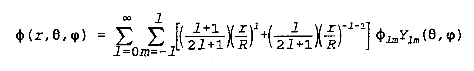
- Y ]m ( ⁇ , ⁇ ) is the spherical harmonic series made up of Legendre Polynomials.
- each ⁇ lm component is determined by integrating the potential at a given point with the spherical harmonic at that point with respect to the solid angle element subtended from the origin to that point. This is an important aspect of the 3D map; its accuracy in creating the 3D map is increased with increased numbers of electrodes in the array and with increased size of the spherical array. In practice it is necessary to compute the ⁇ lm components with the subscript 1 set to 4 or greater. These ⁇ components are stored in an 1 by m array for later determination of potentials anywhere in the volume within the endocardial walls.
- the angle ⁇ ranges from zero to ⁇ radians and ⁇ ranges from zero to 2 ⁇ radians.
- each point on the endocardial wall can now be computed by defining them as r, ⁇ , and ⁇ .
- the graphical representation of the electrical activity on the endocardial surface can be slowed down by 30 to 40 times to present a picture of the ventricular cavity within a time frame useful for human viewing.
- a geometric description of the heart structure is required in order for the algorithm to account for the inherent effect of spatial averaging within the medium (blood). Spatial averaging is a function of both the conductive nature of the medium as well as the physical dimensions of the medium.
- the intramural activation map of Figure 11 is estimated by interpolating between the accurately computed endocardial potentials at locations 23 and 25 ( Figure 7), and actual recorded endocardial value at the surface electrode 24 and an actual recorded intramural value at the subsurface electrode 26 site.
- This first-order estimation of the myocardial activation map assumes that the medium is homogenous and that the medium contains no charge sources. This myocardial activation estimation is limited by the fact that the myocardial medium is not homogeneous and that there are charge sources contained within the myocardial medium. If more than one intramural point was sampled the underlying map of intramural electrical activity could be improved by interpolating between the endocardial surface values and all the sample intramural values.
- V( x ) represents the potential at any desired point defined by the three-dimensional vector x and, V i
- k is an exponent that matches the physical behavior of the tissue medium.
Abstract
Description


Claims
Priority Applications (23)
| Application Number | Priority Date | Filing Date | Title |
|---|---|---|---|
| DE69315354T DE69315354T2 (en) | 1992-09-23 | 1993-09-23 | ENDOCARD-MAPPING SYSTEM |
| EP93922724A EP0661948B1 (en) | 1992-09-23 | 1993-09-23 | Endocardial mapping system |
| JP50843194A JP3581888B2 (en) | 1992-09-23 | 1993-09-23 | Endocardial mapping system |
| US10/706,484 USRE41334E1 (en) | 1992-09-23 | 1993-09-23 | Endocardial mapping system |
| US08/387,832 US6240307B1 (en) | 1993-09-23 | 1993-09-23 | Endocardial mapping system |
| CA2144973A CA2144973C (en) | 1992-09-23 | 1993-09-23 | Endocardial mapping system |
| US09/548,102 US7189208B1 (en) | 1992-09-23 | 2000-04-12 | Method for measuring heart electrophysiology |
| US09/548,057 US6939309B1 (en) | 1993-09-23 | 2000-04-12 | Electrophysiology mapping system |
| US09/547,543 US6990370B1 (en) | 1992-09-23 | 2000-04-12 | Method for mapping heart electrophysiology |
| US09/547,476 US6947785B1 (en) | 1993-09-23 | 2000-04-12 | Interface system for endocardial mapping catheter |
| US09/588,980 US7826881B1 (en) | 1992-09-23 | 2000-06-07 | Endocardial chamber mapping system |
| US09/589,387 US7831288B1 (en) | 1992-09-23 | 2000-06-07 | Method for mapping potential distribution of a heart chamber |
| US10/375,752 US6978168B2 (en) | 1992-09-23 | 2003-02-26 | Software for mapping potential distribution of a heart chamber |
| US10/955,894 US7930012B2 (en) | 1992-09-23 | 2004-09-30 | Chamber location method |
| US11/003,207 US7289843B2 (en) | 1992-09-23 | 2004-12-03 | Software for mapping potential distribution of a heart chamber |
| US11/265,141 US20060058693A1 (en) | 1992-09-23 | 2005-11-03 | Mapping electrophysiological data in a heart chamber |
| US11/265,133 US20060084884A1 (en) | 1992-09-23 | 2005-11-03 | Mapping electrophysiological data in a heart chamber |
| US11/265,142 US8208998B2 (en) | 1992-09-23 | 2005-11-03 | Representing the geometry of a heart chamber |
| US11/265,138 US20060084971A1 (en) | 1992-09-23 | 2005-11-03 | Mapping physiological data in a heart chamber |
| US11/265,139 US20060084972A1 (en) | 1992-09-23 | 2005-11-03 | Delivering ablation therapy in a heart chamber |
| US11/265,137 US20060084970A1 (en) | 1992-09-23 | 2005-11-03 | Mapping physiological data in a heart chamber |
| US11/265,140 US20060058692A1 (en) | 1992-09-23 | 2005-11-03 | Mapping physiological data in a heart chamber |
| US12/131,750 US20080234564A1 (en) | 1992-09-23 | 2008-06-02 | Electrophysiology therapy catheter |
Applications Claiming Priority (4)
| Application Number | Priority Date | Filing Date | Title |
|---|---|---|---|
| US07/950,448 | 1992-09-23 | ||
| US07/950,448 US5297549A (en) | 1992-09-23 | 1992-09-23 | Endocardial mapping system |
| US07/949,690 US5311866A (en) | 1992-09-23 | 1992-09-23 | Heart mapping catheter |
| US07/949,690 | 1992-09-23 |
Related Parent Applications (5)
| Application Number | Title | Priority Date | Filing Date |
|---|---|---|---|
| US07/949,690 Continuation US5311866A (en) | 1992-09-23 | 1992-09-23 | Heart mapping catheter |
| US07/949,690 Continuation-In-Part US5311866A (en) | 1992-09-23 | 1992-09-23 | Heart mapping catheter |
| US07/950,448 Continuation US5297549A (en) | 1992-09-23 | 1992-09-23 | Endocardial mapping system |
| US07/950,448 Continuation-In-Part US5297549A (en) | 1992-09-23 | 1992-09-23 | Endocardial mapping system |
| US95044893A Continuation-In-Part | 1992-09-23 | 1993-09-23 |
Related Child Applications (10)
| Application Number | Title | Priority Date | Filing Date |
|---|---|---|---|
| US08/387,832 A-371-Of-International US6240307B1 (en) | 1992-09-23 | 1993-09-23 | Endocardial mapping system |
| US510598A Continuation-In-Part | 1992-09-23 | 1998-01-09 | |
| US09/107,371 Division US7670297B1 (en) | 1998-06-30 | 1998-06-30 | Chamber mapping system |
| US09/589,387 Division US7831288B1 (en) | 1992-09-23 | 2000-06-07 | Method for mapping potential distribution of a heart chamber |
| US09/589,409 Division US6826421B1 (en) | 1992-09-23 | 2000-06-07 | Endocardial mapping catheter |
| US09/589,408 Division US6647617B1 (en) | 1992-09-23 | 2000-06-07 | Method of construction an endocardial mapping catheter |
| US09/589,407 Division US6826420B1 (en) | 1992-09-23 | 2000-06-07 | Method of mapping a plug in a mapping catheter |
| US09/588,980 Division US7826881B1 (en) | 1992-09-23 | 2000-06-07 | Endocardial chamber mapping system |
| US09/588,930 Division US6603996B1 (en) | 1992-09-23 | 2000-06-07 | Software for mapping potential distribution of a heart chamber |
| US70648403A Continuation | 1992-09-23 | 2003-11-12 |
Publications (1)
| Publication Number | Publication Date |
|---|---|
| WO1994006349A1 true WO1994006349A1 (en) | 1994-03-31 |
Family
ID=27130293
Family Applications (1)
| Application Number | Title | Priority Date | Filing Date |
|---|---|---|---|
| PCT/US1993/009015 WO1994006349A1 (en) | 1992-09-23 | 1993-09-23 | Endocardial mapping system |
Country Status (7)
| Country | Link |
|---|---|
| US (11) | US6826421B1 (en) |
| EP (1) | EP0661948B1 (en) |
| JP (2) | JP3581888B2 (en) |
| AT (1) | ATE160273T1 (en) |
| CA (3) | CA2144973C (en) |
| DE (1) | DE69315354T2 (en) |
| WO (1) | WO1994006349A1 (en) |
Cited By (74)
| Publication number | Priority date | Publication date | Assignee | Title |
|---|---|---|---|---|
| WO1994016619A1 (en) * | 1993-01-29 | 1994-08-04 | Cardima, Inc. | Method intravascular sensing devices for electrical activity |
| US5549109A (en) * | 1993-10-01 | 1996-08-27 | Target Therapeutics, Inc. | Sheathed multipolar catheter and multipolar guidewire for sensing cardiac electrical activity |
| WO1996032897A1 (en) * | 1995-04-20 | 1996-10-24 | Desai Jawahar M | Apparatus for cardiac mapping and ablation |
| WO1996032885A1 (en) * | 1995-04-20 | 1996-10-24 | Desai Jawahar M | Apparatus for cardiac ablation |
| WO1996039929A1 (en) * | 1995-06-07 | 1996-12-19 | Biosense, Inc. | Apparaus and method for treating cardiac arrhythmias with no discrete target |
| WO1997017893A1 (en) * | 1995-11-13 | 1997-05-22 | Heart Rhythm Technologies, Inc. | System and method for analyzing electrogram waveforms |
| US5645064A (en) * | 1992-01-29 | 1997-07-08 | Cardima, Inc. | High resolution intravascular signal detection |
| US5645082A (en) * | 1993-01-29 | 1997-07-08 | Cardima, Inc. | Intravascular method and system for treating arrhythmia |
| WO1997024981A2 (en) * | 1996-01-08 | 1997-07-17 | Biosense Inc. | Cardiac electro-mechanics |
| US5657755A (en) * | 1993-03-11 | 1997-08-19 | Desai; Jawahar M. | Apparatus and method for cardiac ablation |
| EP0893093A1 (en) * | 1997-07-25 | 1999-01-27 | Sulzer Osypka GmbH | Catheter for the endocardial detection of heart potentials |
| WO1999005971A1 (en) * | 1997-08-01 | 1999-02-11 | Cardiac Pathways Corporation | System for electrode localization using ultrasound |
| US5954665A (en) * | 1995-06-07 | 1999-09-21 | Biosense, Inc. | Cardiac ablation catheter using correlation measure |
| EP0974936A2 (en) | 1998-07-24 | 2000-01-26 | Biosense, Inc. | Three-dimensional reconstruction of intrabody organs |
| AU715925B2 (en) * | 1996-01-08 | 2000-02-10 | Biosense, Inc. | Mapping catheter |
| US6088610A (en) * | 1993-01-29 | 2000-07-11 | Cardima, Inc. | Method and system for using multiple intravascular sensing devices to detect electrical activity |
| EP1023870A1 (en) * | 1999-01-28 | 2000-08-02 | Ministero Dell' Universita' E Della Ricerca Scientifica E Tecnologica | Device for localization of endocardial electrodes |
| US6171303B1 (en) | 1996-01-08 | 2001-01-09 | Biosense, Inc. | Methods and apparatus for myocardial revascularization |
| EP1070480A2 (en) | 1999-07-22 | 2001-01-24 | Biosense, Inc. | Vector mapping of three-dimensionally reconstructed intrabody organs and method of display |
| US6200310B1 (en) | 1997-01-08 | 2001-03-13 | Biosense, Inc. | Monitoring of myocardial revascularization |
| US6203493B1 (en) | 1996-02-15 | 2001-03-20 | Biosense, Inc. | Attachment with one or more sensors for precise position determination of endoscopes |
| US6211666B1 (en) | 1996-02-27 | 2001-04-03 | Biosense, Inc. | Object location system and method using field actuation sequences having different field strengths |
| US6253770B1 (en) | 1996-02-15 | 2001-07-03 | Biosense, Inc. | Catheter with lumen |
| US6266551B1 (en) | 1996-02-15 | 2001-07-24 | Biosense, Inc. | Catheter calibration and usage monitoring system |
| US6314310B1 (en) | 1997-02-14 | 2001-11-06 | Biosense, Inc. | X-ray guided surgical location system with extended mapping volume |
| US6321109B2 (en) | 1996-02-15 | 2001-11-20 | Biosense, Inc. | Catheter based surgery |
| US6332089B1 (en) | 1996-02-15 | 2001-12-18 | Biosense, Inc. | Medical procedures and apparatus using intrabody probes |
| US6366799B1 (en) | 1996-02-15 | 2002-04-02 | Biosense, Inc. | Movable transmit or receive coils for location system |
| US6385476B1 (en) | 1999-09-21 | 2002-05-07 | Biosense, Inc. | Method and apparatus for intracardially surveying a condition of a chamber of a heart |
| US6400981B1 (en) | 2000-06-21 | 2002-06-04 | Biosense, Inc. | Rapid mapping of electrical activity in the heart |
| US6443974B1 (en) | 1996-07-28 | 2002-09-03 | Biosense, Inc. | Electromagnetic cardiac biostimulation |
| US6447504B1 (en) | 1998-07-02 | 2002-09-10 | Biosense, Inc. | System for treatment of heart tissue using viability map |
| US6453190B1 (en) | 1996-02-15 | 2002-09-17 | Biosense, Inc. | Medical probes with field transducers |
| WO2002087456A1 (en) * | 2001-05-01 | 2002-11-07 | C.R. Bard, Inc. | Method and apparatus for altering conduction properties in the heart and in adjacent vessels |
| US6522905B2 (en) | 1993-03-11 | 2003-02-18 | Jawahar M. Desai | Apparatus and method for cardiac ablation |
| US6618612B1 (en) | 1996-02-15 | 2003-09-09 | Biosense, Inc. | Independently positionable transducers for location system |
| US6633773B1 (en) | 2000-09-29 | 2003-10-14 | Biosene, Inc. | Area of interest reconstruction for surface of an organ using location data |
| WO2003089997A2 (en) * | 2002-03-15 | 2003-10-30 | C.R. Bard, Inc. | Method and apparatus for control of ablation energy and electrogram acquisition through multiple common electrodes in an electrophysiology catheter |
| US6650927B1 (en) | 2000-08-18 | 2003-11-18 | Biosense, Inc. | Rendering of diagnostic imaging data on a three-dimensional map |
| EP1415608A2 (en) | 2002-10-21 | 2004-05-06 | Biosense, Inc. | Real-time monitoring and mapping of ablation lesion formation in the heart |
| US6788967B2 (en) | 1997-05-14 | 2004-09-07 | Biosense, Inc. | Medical diagnosis, treatment and imaging systems |
| US6837886B2 (en) | 2000-05-03 | 2005-01-04 | C.R. Bard, Inc. | Apparatus and methods for mapping and ablation in electrophysiology procedures |
| EP1566150A2 (en) | 2004-02-23 | 2005-08-24 | Biosense Webster, Inc. | Robotically guided catheter |
| US6957101B2 (en) | 2002-08-21 | 2005-10-18 | Joshua Porath | Transient event mapping in the heart |
| US7255695B2 (en) | 2001-04-27 | 2007-08-14 | C.R. Bard, Inc. | Systems and methods for three-dimensional mapping of electrical activity |
| WO2008014629A2 (en) * | 2006-08-03 | 2008-02-07 | Christoph Scharf | Method and device for determining and presenting surface charge and dipole densities on cardiac walls |
| EP1897490A2 (en) | 2006-09-06 | 2008-03-12 | Biosense Webster, Inc. | Correlation of cardiac electrical maps with body surface measurements |
| US7561907B2 (en) | 2001-12-31 | 2009-07-14 | Biosense Webster, Inc. | Catheter having multiple spines each having electrical mapping and location sensing capabilities |
| US7722604B2 (en) | 2003-03-28 | 2010-05-25 | C.R. Bard, Inc. | Braided mesh catheter |
| US7727229B2 (en) | 2001-05-01 | 2010-06-01 | C.R. Bard, Inc. | Method and apparatus for altering conduction properties in the heart and in adjacent vessels |
| US8050732B2 (en) | 1993-03-11 | 2011-11-01 | Catheffects, Inc. | Apparatus and method for cardiac ablation |
| WO2012016320A1 (en) * | 2010-08-03 | 2012-02-09 | Medtronic Cryocath Lp | Cryogenic medical mapping and treatment device |
| US8249685B2 (en) | 2004-05-17 | 2012-08-21 | C.R. Bard, Inc. | Method and apparatus for mapping and/or ablation of cardiac tissue |
| US8512255B2 (en) | 2008-01-17 | 2013-08-20 | Christoph Scharf | Device and method for the geometric determination of electrical dipole densities on the cardiac wall |
| US9113911B2 (en) | 2012-09-06 | 2015-08-25 | Medtronic Ablation Frontiers Llc | Ablation device and method for electroporating tissue cells |
| US9345540B2 (en) | 2013-03-15 | 2016-05-24 | Medtronic Ablation Frontiers Llc | Contact specific RF therapy balloon |
| US9387031B2 (en) | 2011-07-29 | 2016-07-12 | Medtronic Ablation Frontiers Llc | Mesh-overlayed ablation and mapping device |
| US9474486B2 (en) | 2013-03-08 | 2016-10-25 | St. Jude Medical, Atrial Fibrillation Division, Inc. | Basket for a multi-electrode array catheter |
| USD782686S1 (en) | 2012-08-31 | 2017-03-28 | Acutus Medical, Inc. | Transducer-electrode pair for a catheter |
| EP3178385A1 (en) * | 2015-12-11 | 2017-06-14 | Biosense Webster (Israel) Ltd. | Electrode array catheter with interconnected framework |
| US9757044B2 (en) | 2011-03-10 | 2017-09-12 | Acutus Medical, Inc. | Device and method for the geometric determination of electrical dipole densities on the cardiac wall |
| EP3247002A1 (en) | 2016-05-17 | 2017-11-22 | Biosense Webster (Israel) Ltd. | System and method for catheter connections |
| US10201311B2 (en) | 2013-02-08 | 2019-02-12 | Acutus Medical, Inc. | Expandable catheter assembly with flexible printed circuit board (PCB) electrical pathways |
| WO2019079082A1 (en) | 2017-10-17 | 2019-04-25 | Biosense Webster (Israel) Ltd. | Reusable catheter handle system |
| EP3499466A1 (en) | 2017-12-14 | 2019-06-19 | Biosense Webster (Israel) Ltd. | Epicardial mapping |
| US10593234B2 (en) | 2015-05-12 | 2020-03-17 | Acutus Medical, Inc. | Cardiac virtualization test tank and testing system and method |
| US10588543B2 (en) | 2012-05-23 | 2020-03-17 | Biosense Webster (Israel), Ltd. | Position sensing using electric dipole fields |
| US10653318B2 (en) | 2015-05-13 | 2020-05-19 | Acutus Medical, Inc. | Localization system and method useful in the acquisition and analysis of cardiac information |
| US10828011B2 (en) | 2013-09-13 | 2020-11-10 | Acutus Medical, Inc. | Devices and methods for determination of electrical dipole densities on a cardiac surface |
| US11278231B2 (en) | 2014-03-25 | 2022-03-22 | Acutus Medical, Inc. | Cardiac analysis user interface system and method |
| US11344366B2 (en) | 2015-05-12 | 2022-05-31 | Acutus Medical, Inc. | Ultrasound sequencing system and method |
| US11399759B2 (en) | 2016-05-03 | 2022-08-02 | Acutus Medical, Inc. | Cardiac mapping system with efficiency algorithm |
| WO2022214870A1 (en) * | 2021-04-07 | 2022-10-13 | Btl Medical Technologies S.R.O. | Pulsed field ablation device and method |
| US11564607B2 (en) | 2015-04-30 | 2023-01-31 | The Regents Of The University Of Michigan | Method and system for mapping and analyzing cardiac electrical activity |
Families Citing this family (251)
| Publication number | Priority date | Publication date | Assignee | Title |
|---|---|---|---|---|
| US7930012B2 (en) | 1992-09-23 | 2011-04-19 | St. Jude Medical, Atrial Fibrillation Division, Inc. | Chamber location method |
| CA2144973C (en) * | 1992-09-23 | 2010-02-09 | Graydon Ernest Beatty | Endocardial mapping system |
| US7189208B1 (en) * | 1992-09-23 | 2007-03-13 | Endocardial Solutions, Inc. | Method for measuring heart electrophysiology |
| US7806829B2 (en) | 1998-06-30 | 2010-10-05 | St. Jude Medical, Atrial Fibrillation Division, Inc. | System and method for navigating an ultrasound catheter to image a beating heart |
| US6892091B1 (en) | 2000-02-18 | 2005-05-10 | Biosense, Inc. | Catheter, method and apparatus for generating an electrical map of a chamber of the heart |
| DE10027782A1 (en) * | 2000-06-07 | 2001-12-13 | Biotronik Mess & Therapieg | System for determining the intracorporeal position of a working catheter |
| US20040226556A1 (en) | 2003-05-13 | 2004-11-18 | Deem Mark E. | Apparatus for treating asthma using neurotoxin |
| US8007495B2 (en) | 2004-03-31 | 2011-08-30 | Biosense Webster, Inc. | Catheter for circumferential ablation at or near a pulmonary vein |
| JP2005323702A (en) * | 2004-05-13 | 2005-11-24 | Asahi Intecc Co Ltd | Medical treatment instrument |
| US8755864B2 (en) | 2004-05-28 | 2014-06-17 | St. Jude Medical, Atrial Fibrillation Division, Inc. | Robotic surgical system and method for diagnostic data mapping |
| US9782130B2 (en) | 2004-05-28 | 2017-10-10 | St. Jude Medical, Atrial Fibrillation Division, Inc. | Robotic surgical system |
| US10258285B2 (en) * | 2004-05-28 | 2019-04-16 | St. Jude Medical, Atrial Fibrillation Division, Inc. | Robotic surgical system and method for automated creation of ablation lesions |
| US8528565B2 (en) | 2004-05-28 | 2013-09-10 | St. Jude Medical, Atrial Fibrillation Division, Inc. | Robotic surgical system and method for automated therapy delivery |
| US7974674B2 (en) * | 2004-05-28 | 2011-07-05 | St. Jude Medical, Atrial Fibrillation Division, Inc. | Robotic surgical system and method for surface modeling |
| US7632265B2 (en) * | 2004-05-28 | 2009-12-15 | St. Jude Medical, Atrial Fibrillation Division, Inc. | Radio frequency ablation servo catheter and method |
| US10863945B2 (en) | 2004-05-28 | 2020-12-15 | St. Jude Medical, Atrial Fibrillation Division, Inc. | Robotic surgical system with contact sensing feature |
| US20060036163A1 (en) * | 2004-07-19 | 2006-02-16 | Viswanathan Raju R | Method of, and apparatus for, controlling medical navigation systems |
| US8155910B2 (en) | 2005-05-27 | 2012-04-10 | St. Jude Medical, Atrial Fibrillation Divison, Inc. | Robotically controlled catheter and method of its calibration |
| US7536218B2 (en) * | 2005-07-15 | 2009-05-19 | Biosense Webster, Inc. | Hybrid magnetic-based and impedance-based position sensing |
| KR101222860B1 (en) * | 2005-09-01 | 2013-01-16 | 삼성전자주식회사 | Optical pickup device |
| US8229545B2 (en) | 2005-09-15 | 2012-07-24 | St. Jude Medical, Atrial Fibrillation Division, Inc. | System and method for mapping complex fractionated electrogram information |
| US8038625B2 (en) * | 2005-09-15 | 2011-10-18 | St. Jude Medical, Atrial Fibrillation Division, Inc. | System and method for three-dimensional mapping of electrophysiology information |
| US8403925B2 (en) | 2006-12-06 | 2013-03-26 | St. Jude Medical, Atrial Fibrillation Division, Inc. | System and method for assessing lesions in tissue |
| US20100234730A1 (en) * | 2006-03-31 | 2010-09-16 | National University Corporation Kyoto Institute Of Technology | Image processing device, ultrasonic imaging apparatus including the same, and image processing method |
| US7766896B2 (en) * | 2006-04-25 | 2010-08-03 | Boston Scientific Scimed, Inc. | Variable stiffness catheter assembly |
| US7774051B2 (en) | 2006-05-17 | 2010-08-10 | St. Jude Medical, Atrial Fibrillation Division, Inc. | System and method for mapping electrophysiology information onto complex geometry |
| US7988639B2 (en) * | 2006-05-17 | 2011-08-02 | St. Jude Medical, Atrial Fibrillation Division, Inc. | System and method for complex geometry modeling of anatomy using multiple surface models |
| US7515954B2 (en) * | 2006-06-13 | 2009-04-07 | Rhythmia Medical, Inc. | Non-contact cardiac mapping, including moving catheter and multi-beat integration |
| EP2745773A3 (en) * | 2006-06-13 | 2014-07-02 | Rhythmia Medical, Inc. | Non-contact cardiac mapping, including moving catheter and multi-beat integration |
| US7505810B2 (en) * | 2006-06-13 | 2009-03-17 | Rhythmia Medical, Inc. | Non-contact cardiac mapping, including preprocessing |
| US7729752B2 (en) | 2006-06-13 | 2010-06-01 | Rhythmia Medical, Inc. | Non-contact cardiac mapping, including resolution map |
| WO2008002654A2 (en) * | 2006-06-28 | 2008-01-03 | C.R. Bard, Inc. | Methods and apparatus for assessing and improving electrode contact with cardiac tissue |
| US8068920B2 (en) | 2006-10-03 | 2011-11-29 | Vincent A Gaudiani | Transcoronary sinus pacing system, LV summit pacing, early mitral closure pacing, and methods therefor |
| US20080119697A1 (en) * | 2006-11-20 | 2008-05-22 | General Electric Company | Bidirectional communication interface |
| US9220439B2 (en) | 2006-12-29 | 2015-12-29 | St. Jude Medical, Atrial Fibrillation Division, Inc. | Navigational reference dislodgement detection method and system |
| US8265745B2 (en) | 2006-12-29 | 2012-09-11 | St. Jude Medical, Atrial Fibillation Division, Inc. | Contact sensor and sheath exit sensor |
| US7957784B2 (en) * | 2006-12-29 | 2011-06-07 | St. Jude Medical, Atrial Fibrillation Division, Inc. | Body surface mapping system |
| US7996055B2 (en) * | 2006-12-29 | 2011-08-09 | St. Jude Medical, Atrial Fibrillation Division, Inc. | Cardiac navigation system including electrode array for use therewith |
| US9585586B2 (en) | 2006-12-29 | 2017-03-07 | St. Jude Medical, Atrial Fibrillation Division, Inc. | Navigational reference dislodgement detection method and system |
| US20080190438A1 (en) | 2007-02-08 | 2008-08-14 | Doron Harlev | Impedance registration and catheter tracking |
| US8155756B2 (en) * | 2007-02-16 | 2012-04-10 | Pacesetter, Inc. | Motion-based optimization for placement of cardiac stimulation electrodes |
| US8195292B2 (en) * | 2007-02-16 | 2012-06-05 | Pacestter, Inc. | Cardiac resynchronization therapy optimization using parameter estimation from realtime electrode motion tracking |
| US9549689B2 (en) * | 2007-03-09 | 2017-01-24 | St. Jude Medical, Atrial Fibrillation Division, Inc. | System and method for correction of inhomogeneous fields |
| US7825925B2 (en) * | 2007-03-09 | 2010-11-02 | St. Jude Medical, Atrial Fibrillation Division, Inc. | Method and system for repairing triangulated surface meshes |
| US10433929B2 (en) * | 2007-03-09 | 2019-10-08 | St. Jude Medical, Atrial Fibrillation Division, Inc. | System and method for local deformable registration of a catheter navigation system to image data or a model |
| WO2008136008A2 (en) * | 2007-05-08 | 2008-11-13 | Mediguide Ltd. | Method for producing an electrophysiological map of the heart |
| US9757036B2 (en) * | 2007-05-08 | 2017-09-12 | Mediguide Ltd. | Method for producing an electrophysiological map of the heart |
| JP5337367B2 (en) * | 2007-10-31 | 2013-11-06 | 株式会社東芝 | Medical image display device |
| EP2197377B1 (en) | 2007-11-16 | 2017-11-01 | St. Jude Medical, Atrial Fibrillation Division, Inc. | Device for real-time lesion estimation during ablation |
| US9717501B2 (en) | 2007-11-21 | 2017-08-01 | St. Jude Medical, Atrial Fibrillation Division, Inc. | Methods and systems for occluding vessels during cardiac ablation including optional electroanatomical guidance |
| US8359092B2 (en) * | 2007-11-29 | 2013-01-22 | Biosense Webster, Inc. | Determining locations of ganglia and plexi in the heart using complex fractionated atrial electrogram |
| US9622673B2 (en) * | 2007-12-14 | 2017-04-18 | Siemens Healthcare Gmbh | System for determining electrical status of patient attached leads |
| US20090163801A1 (en) * | 2007-12-19 | 2009-06-25 | St. Jude Medical, Atrial Fibrillation Division, Inc. | System for displaying data relating to energy emitting treatment devices together with electrophysiological mapping data |
| US8103327B2 (en) | 2007-12-28 | 2012-01-24 | Rhythmia Medical, Inc. | Cardiac mapping catheter |
| JP5694778B2 (en) | 2007-12-31 | 2015-04-01 | リアル イメージング リミテッド | Method, apparatus and system for determining the likelihood of the presence of a tumor |
| US8082035B2 (en) * | 2008-01-10 | 2011-12-20 | Bioness Inc. | Methods and apparatus for implanting electronic implants within the body |
| US8483831B1 (en) | 2008-02-15 | 2013-07-09 | Holaira, Inc. | System and method for bronchial dilation |
| WO2009118721A1 (en) * | 2008-03-28 | 2009-10-01 | Real Imaging Ltd. | Method apparatus and system for analyzing thermal images |
| US8538509B2 (en) | 2008-04-02 | 2013-09-17 | Rhythmia Medical, Inc. | Intracardiac tracking system |
| US20090276020A1 (en) * | 2008-05-02 | 2009-11-05 | Pacesetter, Inc. | Tools for delivering implantable medical leads and methods of using and manufacturing such tools |
| JP2011519699A (en) | 2008-05-09 | 2011-07-14 | インノブアトイブエ プルモナルイ ソルウトイオンス,インコーポレイティッド | Systems, assemblies and methods for treatment of bronchial trees |
| US8676303B2 (en) | 2008-05-13 | 2014-03-18 | The Regents Of The University Of California | Methods and systems for treating heart instability |
| EP2326243B1 (en) * | 2008-08-22 | 2017-05-03 | Koninklijke Philips N.V. | Sensing apparatus for sensing an object |
| JP5991706B2 (en) | 2008-10-09 | 2016-09-14 | ザ リージェンツ オブ ザ ユニバーシティ オブ カリフォルニア | Method, system, and apparatus for detection, diagnosis, and treatment of biorhythm disorders |
| US8386010B2 (en) * | 2008-10-23 | 2013-02-26 | Covidien Lp | Surgical tissue monitoring system |
| US8167876B2 (en) | 2008-10-27 | 2012-05-01 | Rhythmia Medical, Inc. | Tracking system using field mapping |
| US9339331B2 (en) * | 2008-12-29 | 2016-05-17 | St. Jude Medical, Atrial Fibrillation Division, Inc. | Non-contact electrode basket catheters with irrigation |
| US8700129B2 (en) | 2008-12-31 | 2014-04-15 | St. Jude Medical, Atrial Fibrillation Division, Inc. | Devices and methods for catheter localization |
| US8900150B2 (en) | 2008-12-30 | 2014-12-02 | St. Jude Medical, Atrial Fibrillation Division, Inc. | Intracardiac imaging system utilizing a multipurpose catheter |
| US9307931B2 (en) * | 2008-12-31 | 2016-04-12 | St. Jude Medical, Atrial Fibrillation Division, Inc. | Multiple shell construction to emulate chamber contraction with a mapping system |
| US9398862B2 (en) | 2009-04-23 | 2016-07-26 | Rhythmia Medical, Inc. | Multi-electrode mapping system |
| US8103338B2 (en) | 2009-05-08 | 2012-01-24 | Rhythmia Medical, Inc. | Impedance based anatomy generation |
| US8571647B2 (en) | 2009-05-08 | 2013-10-29 | Rhythmia Medical, Inc. | Impedance based anatomy generation |
| EP2440131B1 (en) | 2009-06-08 | 2018-04-04 | MRI Interventions, Inc. | Mri-guided interventional systems that can track and generate dynamic visualizations of flexible intrabody devices in near real time |
| US9211074B2 (en) | 2009-06-09 | 2015-12-15 | Safeop Surgical, Inc. | System, method, apparatus, device and computer program product for automatically detecting positioning effect |
| US8396532B2 (en) | 2009-06-16 | 2013-03-12 | MRI Interventions, Inc. | MRI-guided devices and MRI-guided interventional systems that can track and generate dynamic visualizations of the devices in near real time |
| US8406848B2 (en) * | 2009-10-06 | 2013-03-26 | Seiko Epson Corporation | Reconstructing three-dimensional current sources from magnetic sensor data |
| US10398326B2 (en) | 2013-03-15 | 2019-09-03 | The Regents Of The University Of California | System and method of identifying sources associated with biological rhythm disorders |
| US9332915B2 (en) | 2013-03-15 | 2016-05-10 | The Regents Of The University Of California | System and method to identify sources associated with biological rhythm disorders |
| US10434319B2 (en) | 2009-10-09 | 2019-10-08 | The Regents Of The University Of California | System and method of identifying sources associated with biological rhythm disorders |
| US9392948B2 (en) | 2011-12-09 | 2016-07-19 | The Regents Of The University Of California | System and method of identifying sources for biological rhythms |
| KR101722290B1 (en) | 2009-10-27 | 2017-03-31 | 호라이라 인코포레이티드 | Delivery devices with coolable energy emitting assemblies |
| CN102711645B (en) | 2009-11-11 | 2016-12-28 | 赫莱拉公司 | For processing tissue and controlling narrow system and device |
| US8911439B2 (en) | 2009-11-11 | 2014-12-16 | Holaira, Inc. | Non-invasive and minimally invasive denervation methods and systems for performing the same |
| US20110199286A1 (en) * | 2010-02-13 | 2011-08-18 | Robin Dziama | Spherical Electronic LCD Display |
| US20110213260A1 (en) * | 2010-02-26 | 2011-09-01 | Pacesetter, Inc. | Crt lead placement based on optimal branch selection and optimal site selection |
| RU2559639C2 (en) | 2010-04-08 | 2015-08-10 | Де Реджентс Оф Де Юниверсити Оф Калифорния | Methods, system and device for detecting, diagnosing and treating biological rhythm disturbance |
| US9131869B2 (en) | 2010-05-11 | 2015-09-15 | Rhythmia Medical, Inc. | Tracking using field mapping |
| US8603004B2 (en) | 2010-07-13 | 2013-12-10 | St. Jude Medical, Atrial Fibrillation Division, Inc. | Methods and systems for filtering respiration noise from localization data |
| US9655666B2 (en) * | 2010-10-29 | 2017-05-23 | Medtronic Ablatio Frontiers LLC | Catheter with coronary sinus ostium anchor |
| US8560086B2 (en) | 2010-12-02 | 2013-10-15 | St. Jude Medical, Atrial Fibrillation Division, Inc. | Catheter electrode assemblies and methods of construction therefor |
| JP5795080B2 (en) | 2010-12-17 | 2015-10-14 | セント・ジュード・メディカル・エイトリアル・フィブリレーション・ディヴィジョン・インコーポレーテッド | Navigation standard deviation detection method and system |
| US9061155B2 (en) | 2010-12-23 | 2015-06-23 | Medtronic, Inc. | Implanted device data to guide ablation therapy |
| US9095715B2 (en) | 2010-12-23 | 2015-08-04 | Medtronic, Inc. | Implanted device data to guide ablation therapy |
| US9002442B2 (en) | 2011-01-13 | 2015-04-07 | Rhythmia Medical, Inc. | Beat alignment and selection for cardiac mapping |
| US8428700B2 (en) | 2011-01-13 | 2013-04-23 | Rhythmia Medical, Inc. | Electroanatomical mapping |
| US10918307B2 (en) | 2011-09-13 | 2021-02-16 | St. Jude Medical, Atrial Fibrillation Division, Inc. | Catheter navigation using impedance and magnetic field measurements |
| US9901303B2 (en) | 2011-04-14 | 2018-02-27 | St. Jude Medical, Atrial Fibrillation Division, Inc. | System and method for registration of multiple navigation systems to a common coordinate frame |
| US10362963B2 (en) | 2011-04-14 | 2019-07-30 | St. Jude Medical, Atrial Fibrillation Division, Inc. | Correction of shift and drift in impedance-based medical device navigation using magnetic field information |
| ITPD20110125A1 (en) * | 2011-04-15 | 2012-10-16 | Elvido Medical Technology Srl | CENTRAL VENOUS CATHETER |
| WO2012145072A1 (en) | 2011-04-22 | 2012-10-26 | Topera, Inc. | Basket style cardiac mapping catheter having a flexible electrode assembly for detection of cardiac rhythm disorders |
| US9050006B2 (en) | 2011-05-02 | 2015-06-09 | The Regents Of The University Of California | System and method for reconstructing cardiac activation information |
| US8165666B1 (en) | 2011-05-02 | 2012-04-24 | Topera, Inc. | System and method for reconstructing cardiac activation information |
| US9107600B2 (en) | 2011-05-02 | 2015-08-18 | The Regents Of The University Of California | System and method for reconstructing cardiac activation information |
| EP2705464B1 (en) | 2011-05-02 | 2018-04-18 | Topera, Inc. | System and method for targeting heart rhythm disorders using shaped ablation |
| JP6139518B2 (en) * | 2011-07-05 | 2017-05-31 | カーディオインサイト テクノロジーズ インコーポレイテッド | Positioning for ECG mapping |
| EP2729214B1 (en) * | 2011-07-05 | 2019-09-04 | CardioInsight Technologies, Inc. | System to facilitate providing therapy to a patient |
| US8620417B2 (en) | 2011-09-22 | 2013-12-31 | Biosense Webster (Israel), Ltd. | Graphic user interface for physical parameter mapping |
| WO2013101923A1 (en) | 2011-12-29 | 2013-07-04 | St. Jude Medical, Atrial Fibrillation Division, Inc. | System for optimized coupling of ablation catheters to body tissues and evaluation of lesions formed by the catheters |
| US10391012B2 (en) | 2012-05-02 | 2019-08-27 | Safeop Surgical Inc. | System, method, and computer algorithm and characterization and classification of electrophysiological evoked potentials |
| EP2879576A4 (en) * | 2012-07-30 | 2016-07-13 | Univ Northwestern | Radiofrequency probe for circumferential ablation of a hollow cavity |
| US9895079B2 (en) * | 2012-09-26 | 2018-02-20 | Biosense Webster (Israel) Ltd. | Electropotential mapping |
| WO2014100464A1 (en) | 2012-12-20 | 2014-06-26 | Boston Scientific Scimed, Inc. | Rotor identification using sequential pattern matching |
| US9398933B2 (en) | 2012-12-27 | 2016-07-26 | Holaira, Inc. | Methods for improving drug efficacy including a combination of drug administration and nerve modulation |
| US10912476B2 (en) | 2013-01-16 | 2021-02-09 | University Of Vermont | Catheters, systems, and related methods for mapping, minimizing, and treating cardiac fibrillation |
| US9693699B2 (en) | 2013-01-16 | 2017-07-04 | University Of Vermont | Methods and systems for mapping cardiac fibrillation |
| US9026196B2 (en) | 2013-03-05 | 2015-05-05 | St. Jude Medical, Atrial Fibrillation Division, Inc. | System and method for detecting sheathing and unsheathing of localization elements |
| US10188314B2 (en) | 2013-03-05 | 2019-01-29 | St. Jude Medical, Cardiology Division, Inc. | System and method for detecting sheathing and unsheathing of localization elements |
| WO2014150509A1 (en) * | 2013-03-15 | 2014-09-25 | Intuitive Surgical Operations, Inc. | Shape sensor systems for tracking interventional instruments and methods of use |
| US8715199B1 (en) | 2013-03-15 | 2014-05-06 | Topera, Inc. | System and method to define a rotational source associated with a biological rhythm disorder |
| US20140330270A1 (en) * | 2013-05-03 | 2014-11-06 | William J. Anderson | Method of ablating scar tissue to orient electrical current flow |
| JP6240751B2 (en) | 2013-05-06 | 2017-11-29 | ボストン サイエンティフィック サイムド,インコーポレイテッドBoston Scientific Scimed,Inc. | Anatomic mapping system for continuous display of recent heart rate characteristics during real-time or playback electrophysiological data visualization |
| JP6408563B2 (en) * | 2013-05-07 | 2018-10-17 | セント・ジュード・メディカル・エイトリアル・フィブリレーション・ディヴィジョン・インコーポレーテッド | Using the spatial arrangement of electrodes to characterize cardiac conduction status |
| US9918649B2 (en) | 2013-05-14 | 2018-03-20 | Boston Scientific Scimed Inc. | Representation and identification of activity patterns during electro-physiology mapping using vector fields |
| JP6117433B2 (en) | 2013-05-16 | 2017-04-19 | ボストン サイエンティフィック サイムド,インコーポレイテッドBoston Scientific Scimed,Inc. | An anatomical mapping system for optimization of enhanced activity start time by similarity-based pattern matching |
| US9576107B2 (en) * | 2013-07-09 | 2017-02-21 | Biosense Webster (Israel) Ltd. | Model based reconstruction of the heart from sparse samples |
| US9775578B2 (en) | 2013-08-12 | 2017-10-03 | Biosense Webster (Israel) Ltd. | Unmapped region visualization |
| US20150057507A1 (en) * | 2013-08-20 | 2015-02-26 | St. Jude Medical, Atrial Fibrillation Division, Inc. | System and Method for Generating Electrophysiology Maps |
| EP3038522B1 (en) | 2013-08-28 | 2023-05-31 | Boston Scientific Scimed Inc. | Estimating the prevalence of activation patterns in data segments during electrophysiology mapping |
| US9220435B2 (en) | 2013-10-09 | 2015-12-29 | St. Jude Medical, Cardiology Division, Inc. | System and method for generating electrophysiology maps |
| CN105592778B (en) | 2013-10-14 | 2019-07-23 | 波士顿科学医学有限公司 | High-resolution cardiac mapping electrod-array conduit |
| US9717429B2 (en) | 2013-10-31 | 2017-08-01 | St. Jude Medical, Cardiology Division, Inc. | System and method for analyzing biological signals and generating electrophyisology maps |
| JP6203951B2 (en) * | 2013-10-31 | 2017-09-27 | ボストン サイエンティフィック サイムド,インコーポレイテッドBoston Scientific Scimed,Inc. | Medical device for high resolution mapping using local matching |
| US9301713B2 (en) | 2013-11-19 | 2016-04-05 | Pacesetter, Inc. | Method and system to assess mechanical dyssynchrony based on motion data collected by a navigation system |
| US9314191B2 (en) | 2013-11-19 | 2016-04-19 | Pacesetter, Inc. | Method and system to measure cardiac motion using a cardiovascular navigation system |
| US9814406B2 (en) | 2013-11-19 | 2017-11-14 | Pacesetter, Inc. | Method and system to identify motion data associated with consistent electrical and mechanical behavior for a region of interest |
| US10568686B2 (en) | 2013-11-21 | 2020-02-25 | Biosense Webster (Israel) Ltd. | Multi-electrode balloon catheter with circumferential and point electrodes |
| WO2015095577A1 (en) | 2013-12-20 | 2015-06-25 | St. Jude Medical, Cardiology Division, Inc. | Coaxial electrode catheters for extracting electrophysiologic parameters |
| US9861823B2 (en) | 2014-05-05 | 2018-01-09 | Pacesetter, Inc. | Cardiac resynchronization system and method |
| US9895076B2 (en) | 2014-05-05 | 2018-02-20 | Pacesetter, Inc. | Method and system to determine cardiac cycle length in connection with cardiac mapping |
| US9700233B2 (en) | 2014-05-05 | 2017-07-11 | Pacesetter, Inc. | Method and system to equalizing cardiac cycle length between map points |
| US10105077B2 (en) | 2014-05-05 | 2018-10-23 | Pacesetter, Inc. | Method and system for calculating strain from characterization data of a cardiac chamber |
| US9302099B2 (en) | 2014-05-05 | 2016-04-05 | Pacesetter, Inc. | System and method for evaluating lead stability of an implantable medical device |
| US9763591B2 (en) | 2014-05-05 | 2017-09-19 | Pacesetter, Inc. | Method and system to subdivide a mapping area for mechanical activation analysis |
| US9364170B2 (en) | 2014-05-05 | 2016-06-14 | Pacesetter, Inc. | Method and system to characterize motion data based on neighboring map points |
| US9380940B2 (en) | 2014-05-05 | 2016-07-05 | Pacesetter, Inc. | Method and system for displaying a three dimensional visualization of cardiac motion |
| US10285647B2 (en) | 2014-05-05 | 2019-05-14 | Pacesetter Inc. | Method and system to automatically assign map points to anatomical segments and determine mechanical activation time |
| WO2015187386A1 (en) | 2014-06-03 | 2015-12-10 | Boston Scientific Scimed, Inc. | Electrode assembly having an atraumatic distal tip |
| WO2015187430A2 (en) | 2014-06-04 | 2015-12-10 | Boston Scientific Scimed, Inc. | Electrode assembly |
| EP3157419A1 (en) | 2014-06-20 | 2017-04-26 | Boston Scientific Scimed Inc. | Medical devices for mapping cardiac tissue |
| US10568540B2 (en) | 2014-09-26 | 2020-02-25 | Cardioinsight Technologies, Inc. | Localization of objects within a conductive volume |
| CN107072574B (en) | 2014-10-15 | 2020-06-12 | 圣犹达医疗用品心脏病学部门有限公司 | Method and system for mapping local conduction velocity |
| WO2016061387A1 (en) | 2014-10-15 | 2016-04-21 | St. Jude Medical, Cardiology Division, Inc. | Methods and systems for generating integrated substrate maps for cardiac arrhythmias |
| EP3215215A2 (en) * | 2014-11-09 | 2017-09-13 | Senso Medical Labs Ltd. | Electrode lead |
| US20170354395A1 (en) | 2015-01-07 | 2017-12-14 | St. Jude Medical, Cardiology Division, Inc. | Imaging Device |
| JP6633082B2 (en) | 2015-01-07 | 2020-01-22 | セント・ジュード・メディカル,カーディオロジー・ディヴィジョン,インコーポレイテッド | System, method, and apparatus for visualizing cardiac timing information using animation |
| US9833161B2 (en) * | 2015-02-09 | 2017-12-05 | Biosense Webster (Israel) Ltd. | Basket catheter with far-field electrode |
| WO2016176567A1 (en) | 2015-04-29 | 2016-11-03 | Innoblative Designs, Inc. | Cavitary tissue ablation |
| US11197640B2 (en) | 2015-05-04 | 2021-12-14 | Safeop Surgical, Inc. | System, method, and computer algorithm for measuring, displaying, and accurately detecting changes in electrophysiological evoked potentials |
| EP3261535B1 (en) | 2015-05-07 | 2019-07-17 | St. Jude Medical, Cardiology Division, Inc. | System for detecting sheathing and unsheathing of localization elements |
| US10238350B2 (en) | 2015-05-08 | 2019-03-26 | St. Jude Medical, Cardiology Division, Inc. | System and method for real-time electrophysiological mapping |
| WO2016181316A1 (en) | 2015-05-12 | 2016-11-17 | Navix International Limited | Systems and methods for tracking an intrabody catheter |
| JP2018520718A (en) | 2015-05-12 | 2018-08-02 | ナヴィックス インターナショナル リミテッドNavix International Limited | Contact quality evaluation by dielectric property analysis |
| WO2016181318A1 (en) | 2015-05-12 | 2016-11-17 | Navix International Limited | Lesion assessment by dielectric property analysis |
| WO2016181317A2 (en) | 2015-05-12 | 2016-11-17 | Navix International Limited | Calculation of an ablation plan |
| CN107920740B (en) | 2015-08-20 | 2020-11-24 | 波士顿科学医学有限公司 | Flexible electrodes for cardiac sensing and methods of making the same |
| WO2017040581A1 (en) | 2015-09-02 | 2017-03-09 | St. Jude Medical, Cardiology Division, Inc. | Methods and systems for identifying and mapping cardiac activation wavefronts |
| WO2017041892A1 (en) | 2015-09-07 | 2017-03-16 | Ablacon Inc. | System for analyzing electrophysiological data and method for analyzing electrophysiological data |
| EP3352648B1 (en) | 2015-09-26 | 2022-10-26 | Boston Scientific Scimed Inc. | Multiple rhythm template monitoring |
| EP3353753A1 (en) | 2015-09-26 | 2018-08-01 | Boston Scientific Scimed Inc. | Systems and methods for anatomical shell editing |
| US10271758B2 (en) | 2015-09-26 | 2019-04-30 | Boston Scientific Scimed, Inc. | Intracardiac EGM signals for beat matching and acceptance |
| US10405766B2 (en) | 2015-09-26 | 2019-09-10 | Boston Scientific Scimed, Inc. | Method of exploring or mapping internal cardiac structures |
| CN108348186B (en) | 2015-10-07 | 2021-06-18 | 圣犹达医疗用品心脏病学部门有限公司 | Method and system for mapping cardiac restitution |
| WO2017062247A1 (en) | 2015-10-07 | 2017-04-13 | St. Jude Medical, Cardiology Division, Inc. | Methods and systems for mapping cardiac repolarization |
| WO2017075366A1 (en) | 2015-10-29 | 2017-05-04 | Innoblative Designs, Inc. | Screen sphere tissue ablation devices and methods |
| CN108471975B (en) | 2015-12-04 | 2020-11-17 | 圣犹达医疗用品心脏病学部门有限公司 | Method and system for statistically analyzing electrograms of and mapping locally abnormal ventricular activity |
| WO2017136262A1 (en) | 2016-02-02 | 2017-08-10 | Innoblative Designs, Inc. | Cavitary tissue ablation system |
| JP2019508127A (en) | 2016-02-16 | 2019-03-28 | セント・ジュード・メディカル,カーディオロジー・ディヴィジョン,インコーポレイテッド | Method and system for electrophysiological mapping using medical images |
| WO2017151347A1 (en) | 2016-03-01 | 2017-09-08 | St. Jude Medical, Cardiology Division, Inc. | Methods and systems for mapping cardiac activity |
| US10869714B2 (en) | 2016-03-01 | 2020-12-22 | Innoblative Designs, Inc. | Resecting and coagulating tissue |
| EP3484362A1 (en) | 2016-07-14 | 2019-05-22 | Navix International Limited | Characteristic track catheter navigation |
| WO2018075389A1 (en) | 2016-10-17 | 2018-04-26 | Innoblative Designs, Inc. | Treatment devices and methods |
| US11266467B2 (en) | 2016-10-25 | 2022-03-08 | Navix International Limited | Systems and methods for registration of intra-body electrical readings with a pre-acquired three dimensional image |
| US10912602B2 (en) | 2016-11-08 | 2021-02-09 | Innoblative Designs, Inc. | Electrosurgical tissue and vessel sealing device |
| EP3500157B1 (en) | 2016-11-11 | 2021-05-19 | St. Jude Medical, Cardiology Division, Inc. | System and method for generating electrophysiology maps |
| CN110177500B (en) | 2016-11-16 | 2022-03-04 | 纳维斯国际有限公司 | Dynamic visual rendering of tissue models |
| WO2018092071A1 (en) | 2016-11-16 | 2018-05-24 | Navix International Limited | Estimators for ablation effectiveness |
| US10709507B2 (en) | 2016-11-16 | 2020-07-14 | Navix International Limited | Real-time display of treatment-related tissue changes using virtual material |
| WO2018092062A1 (en) | 2016-11-16 | 2018-05-24 | Navix International Limited | Real-time display of tissue deformation by interactions with an intra-body probe |
| US11331029B2 (en) | 2016-11-16 | 2022-05-17 | Navix International Limited | Esophagus position detection by electrical mapping |
| WO2018094063A1 (en) | 2016-11-21 | 2018-05-24 | St. Jude Medical, Cardiology Division, Inc. | System and method for generating electrophysiology maps |
| CN106691438B (en) * | 2016-12-07 | 2022-05-31 | 首都医科大学附属北京安贞医院 | Whole heart three-dimensional mapping system for complex arrhythmia |
| US11730395B2 (en) | 2017-01-12 | 2023-08-22 | Navix International Limited | Reconstruction of an anatomical structure from intrabody measurements |
| US11311204B2 (en) | 2017-01-12 | 2022-04-26 | Navix International Limited | Systems and methods for reconstruction of intrabody electrical readings to anatomical structure |
| US11471067B2 (en) | 2017-01-12 | 2022-10-18 | Navix International Limited | Intrabody probe navigation by electrical self-sensing |
| CN110167432B (en) | 2017-01-13 | 2023-03-10 | 圣犹达医疗用品心脏病学部门有限公司 | System and method for generating an electrophysiology map of ventricular premature beats |
| US10952793B2 (en) | 2017-01-25 | 2021-03-23 | Biosense Webster (Israel) Ltd. | Method and system for eliminating a broad range of cardiac conditions by analyzing intracardiac signals providing a detailed map and determining potential ablation points |
| US10893819B2 (en) | 2017-01-25 | 2021-01-19 | Biosense Webster (Israel) Ltd. | Analyzing and mapping ECG signals and determining ablation points to eliminate Brugada syndrome |
| US10888379B2 (en) | 2017-01-25 | 2021-01-12 | Biosense Webster (Israel) Ltd. | Analyzing and mapping ECG signals and determining ablation points to eliminate brugada syndrome |
| WO2018160631A1 (en) | 2017-03-02 | 2018-09-07 | St. Jude Medical, Cardiology Division, Inc. | System and method for differentiation of adipose tissue from scar tissue during electrophysiological mapping |
| WO2018204375A1 (en) | 2017-05-04 | 2018-11-08 | St. Jude Medical, Cardiology Division, Inc. | System and method for determining ablation parameters |
| JP6883117B2 (en) | 2017-05-17 | 2021-06-09 | セント・ジュード・メディカル,カーディオロジー・ディヴィジョン,インコーポレイテッド | Systems and methods for mapping local activity time (LAT) |
| US20180344202A1 (en) * | 2017-05-30 | 2018-12-06 | Biosense Webster (Israel) Ltd. | Catheter Splines as Location Sensors |
| US11298066B2 (en) | 2017-07-07 | 2022-04-12 | St. Jude Medical, Cardiology Division, Inc. | System and method for electrophysiological mapping |
| WO2019018182A1 (en) | 2017-07-19 | 2019-01-24 | St. Jude Medical, Cardiology Division, Inc. | System and method for electrophysiological mapping |
| EP3658053B1 (en) | 2017-07-26 | 2023-09-13 | Innoblative Designs, Inc. | Minimally invasive articulating assembly having ablation capabilities |
| CN111050641B (en) | 2017-08-17 | 2023-06-09 | 纳维斯国际有限公司 | Remote imaging based on field gradients |
| EP3675729A1 (en) | 2017-09-01 | 2020-07-08 | St. Jude Medical, Cardiology Division, Inc. | System and method for visualizing a proximity of a catheter electrode to a 3d geometry of biological tissue |
| EP3651636B1 (en) | 2017-09-18 | 2022-04-13 | St. Jude Medical, Cardiology Division, Inc. | System and method for sorting electrophysiological signals from multi-dimensional catheters |
| CN111557034B (en) | 2018-01-09 | 2023-12-29 | 圣犹达医疗用品心脏病学部门有限公司 | System and method for classifying electrophysiological signals on a virtual catheter |
| US11399763B2 (en) | 2018-02-12 | 2022-08-02 | St. Jude Medical, Cardiology Division, Inc. | System and method for mapping cardiac muscle fiber orientation |
| US11103177B2 (en) | 2018-04-18 | 2021-08-31 | St, Jude Medical, Cardiology Division, Inc. | System and method for mapping cardiac activity |
| CN112004463B (en) | 2018-04-26 | 2024-03-22 | 圣犹达医疗用品心脏病学部门有限公司 | Systems and methods for mapping arrhythmia driver sites |
| US11071486B2 (en) | 2018-06-01 | 2021-07-27 | St. Jude Medical, Cardiology Division, Inc. | System and method for generating activation timing maps |
| WO2019241079A1 (en) | 2018-06-14 | 2019-12-19 | St. Jude Medical, Cardiology Division, Inc. | System and method for mapping cardiac activity |
| US11369306B2 (en) | 2018-09-10 | 2022-06-28 | St. Jude Medical, Cardiology Division, Inc. | System and method for displaying electrophysiological signals from multi-dimensional catheters |
| WO2020055506A1 (en) | 2018-09-12 | 2020-03-19 | St. Jude Medical, Cardiology Division, Inc. | System and method for generating three dimensional geometric models of anatomical regions |
| US11577075B1 (en) | 2018-10-12 | 2023-02-14 | Vincent A. Gaudiani | Transcoronary sinus pacing of his bundle |
| US11648397B1 (en) | 2018-10-12 | 2023-05-16 | Vincent Gaudiani | Transcoronary sinus pacing of posteroseptal left ventricular base |
| WO2020106604A1 (en) * | 2018-11-20 | 2020-05-28 | Boston Scientific Scimed Inc | Systems for autonomous cardiac mapping |
| EP3846684B1 (en) | 2019-01-03 | 2023-02-01 | St. Jude Medical, Cardiology Division, Inc. | System and method for mapping cardiac activation wavefronts |
| US20220142545A1 (en) | 2019-03-08 | 2022-05-12 | St. Jude Medical, Cardiology Division, Inc. | High density electrode catheters |
| US20220142553A1 (en) | 2019-03-12 | 2022-05-12 | St. Jude Medical, Cardiology Division, Inc. | System and method for cardiac mapping |
| US20220167899A1 (en) | 2019-04-04 | 2022-06-02 | St. Jude Medical Cardiology Division, Inc. | System and method for cardiac mapping |
| EP3923793B1 (en) | 2019-04-18 | 2023-10-18 | St. Jude Medical, Cardiology Division, Inc. | System and method for cardiac mapping |
| EP3948825A1 (en) | 2019-04-24 | 2022-02-09 | St. Jude Medical, Cardiology Division, Inc. | System, method, and apparatus for visualizing cardiac activation |
| EP3923796B1 (en) | 2019-05-09 | 2022-12-07 | St. Jude Medical, Cardiology Division, Inc. | System and method for detection and mapping of near field conduction in scar tissue |
| US11564610B2 (en) | 2019-05-23 | 2023-01-31 | Biosense Webster (Israel) Ltd. | Volumetric LAT map |
| EP3923797B1 (en) | 2019-05-24 | 2023-11-01 | St. Jude Medical, Cardiology Division, Inc. | System and method for cardiac mapping |
| US10939863B2 (en) * | 2019-05-28 | 2021-03-09 | Biosense Webster (Israel) Ltd. | Determining occurrence of focal and/or rotor arrhythmogenic activity in cardiac tissue regions |
| US11717139B2 (en) | 2019-06-19 | 2023-08-08 | Bolt Medical, Inc. | Plasma creation via nonaqueous optical breakdown of laser pulse energy for breakup of vascular calcium |
| WO2020256898A1 (en) | 2019-06-19 | 2020-12-24 | Boston Scientific Scimed, Inc. | Balloon surface photoacoustic pressure wave generation to disrupt vascular lesions |
| US11660427B2 (en) | 2019-06-24 | 2023-05-30 | Boston Scientific Scimed, Inc. | Superheating system for inertial impulse generation to disrupt vascular lesions |
| US11517713B2 (en) | 2019-06-26 | 2022-12-06 | Boston Scientific Scimed, Inc. | Light guide protection structures for plasma system to disrupt vascular lesions |
| US11583339B2 (en) | 2019-10-31 | 2023-02-21 | Bolt Medical, Inc. | Asymmetrical balloon for intravascular lithotripsy device and method |
| US11504023B2 (en) | 2019-12-16 | 2022-11-22 | Biosense Webster (Israel) Ltd. | Sparse calibration of magnetic field created by coils in metal-rich environment |
| EP4042378A1 (en) | 2020-01-24 | 2022-08-17 | St. Jude Medical, Cardiology Division, Inc. | System and method for generating three dimensional geometric models of anatomical regions |
| US11672599B2 (en) | 2020-03-09 | 2023-06-13 | Bolt Medical, Inc. | Acoustic performance monitoring system and method within intravascular lithotripsy device |
| CN115243616A (en) | 2020-03-16 | 2022-10-25 | 圣犹达医疗用品心脏病学部门有限公司 | Systems, methods, and devices for mapping local activation times |
| US20210290286A1 (en) | 2020-03-18 | 2021-09-23 | Bolt Medical, Inc. | Optical analyzer assembly and method for intravascular lithotripsy device |
| US11707323B2 (en) | 2020-04-03 | 2023-07-25 | Bolt Medical, Inc. | Electrical analyzer assembly for intravascular lithotripsy device |
| JP7442677B2 (en) | 2020-04-21 | 2024-03-04 | セント・ジュード・メディカル,カーディオロジー・ディヴィジョン,インコーポレイテッド | System and method for mapping cardiac activity |
| US11751794B2 (en) | 2020-05-19 | 2023-09-12 | St. Jude Medical, Cardiology Division, Inc. | System and method for mapping electrophysiological activation |
| US11896317B2 (en) | 2020-08-04 | 2024-02-13 | Mazor Robotics Ltd. | Triangulation of item in patient body |
| US11672585B2 (en) | 2021-01-12 | 2023-06-13 | Bolt Medical, Inc. | Balloon assembly for valvuloplasty catheter system |
| US11648057B2 (en) | 2021-05-10 | 2023-05-16 | Bolt Medical, Inc. | Optical analyzer assembly with safety shutdown system for intravascular lithotripsy device |
| US11806075B2 (en) | 2021-06-07 | 2023-11-07 | Bolt Medical, Inc. | Active alignment system and method for laser optical coupling |
| WO2023028133A1 (en) | 2021-08-26 | 2023-03-02 | St. Jude Medical, Cardiology Division, Inc. | Method and system for generating respiration signals for use in electrophysiology procedures |
| US11839391B2 (en) | 2021-12-14 | 2023-12-12 | Bolt Medical, Inc. | Optical emitter housing assembly for intravascular lithotripsy device |
| WO2023114588A1 (en) | 2021-12-17 | 2023-06-22 | St. Jude Medical, Cardiology Division, Inc. | Method and system for visualizing ablation procedure data |
| JP2023122622A (en) | 2022-02-23 | 2023-09-04 | セント・ジュード・メディカル,カーディオロジー・ディヴィジョン,インコーポレイテッド | Method and system for tracking and visualizing medical devices |
Citations (6)
| Publication number | Priority date | Publication date | Assignee | Title |
|---|---|---|---|---|
| FR2569103A1 (en) * | 1984-08-14 | 1986-02-21 | Consiglio Nazionale Ricerche | CATHETER FOR THE INTRACARDIAC ELECTRICAL POTENTIAL FIELD |
| US4660571A (en) * | 1985-07-18 | 1987-04-28 | Cordis Corporation | Percutaneous lead having radially adjustable electrode |
| US4699147A (en) * | 1985-09-25 | 1987-10-13 | Cordis Corporation | Intraventricular multielectrode cardial mapping probe and method for using same |
| US4777955A (en) * | 1987-11-02 | 1988-10-18 | Cordis Corporation | Left ventricle mapping probe |
| US4890623A (en) * | 1988-03-14 | 1990-01-02 | C. R. Bard, Inc. | Biopotential sensing device and method for making |
| US4911174A (en) * | 1989-02-13 | 1990-03-27 | Cardiac Pacemakers, Inc. | Method for matching the sense length of an impedance measuring catheter to a ventricular chamber |
Family Cites Families (121)
| Publication number | Priority date | Publication date | Assignee | Title |
|---|---|---|---|---|
| US4042486A (en) * | 1974-06-24 | 1977-08-16 | Kureha Kagaku Kogyo Kabushiki Kaisha | Process for the conversion of pitch into crystalloidal pitch |
| US3954098A (en) | 1975-01-31 | 1976-05-04 | Dick Donald E | Synchronized multiple image tomographic cardiography |
| US4173228A (en) | 1977-05-16 | 1979-11-06 | Applied Medical Devices | Catheter locating device |
| US4380237A (en) | 1979-12-03 | 1983-04-19 | Massachusetts General Hospital | Apparatus for making cardiac output conductivity measurements |
| US4304239A (en) | 1980-03-07 | 1981-12-08 | The Kendall Company | Esophageal probe with balloon electrode |
| US4431005A (en) | 1981-05-07 | 1984-02-14 | Mccormick Laboratories, Inc. | Method of and apparatus for determining very accurately the position of a device inside biological tissue |
| US4750494A (en) * | 1981-05-12 | 1988-06-14 | Medtronic, Inc. | Automatic implantable fibrillation preventer |
| US4444195A (en) | 1981-11-02 | 1984-04-24 | Cordis Corporation | Cardiac lead having multiple ring electrodes |
| US4572206A (en) | 1982-04-21 | 1986-02-25 | Purdue Research Foundation | Method and apparatus for measuring cardiac output |
| US4572486A (en) * | 1982-07-14 | 1986-02-25 | Metcast Associates, Inc. | Molten metal filtering vessel with internal filter |
| US4559951A (en) | 1982-11-29 | 1985-12-24 | Cardiac Pacemakers, Inc. | Catheter assembly |
| US4478223A (en) * | 1982-12-06 | 1984-10-23 | Allor Douglas R | Three dimensional electrocardiograph |
| US4613866A (en) | 1983-05-13 | 1986-09-23 | Mcdonnell Douglas Corporation | Three dimensional digitizer with electromagnetic coupling |
| US4522212A (en) | 1983-11-14 | 1985-06-11 | Mansfield Scientific, Inc. | Endocardial electrode |
| US4572186A (en) | 1983-12-07 | 1986-02-25 | Cordis Corporation | Vessel dilation |
| US4573473A (en) | 1984-04-13 | 1986-03-04 | Cordis Corporation | Cardiac mapping probe |
| US4697595A (en) | 1984-07-24 | 1987-10-06 | Telectronics N.V. | Ultrasonically marked cardiac catheters |
| US4628937A (en) | 1984-08-02 | 1986-12-16 | Cordis Corporation | Mapping electrode assembly |
| US4706670A (en) | 1985-11-26 | 1987-11-17 | Meadox Surgimed A/S | Dilatation catheter |
| US4674518A (en) * | 1985-09-06 | 1987-06-23 | Cardiac Pacemakers, Inc. | Method and apparatus for measuring ventricular volume |
| DE3536658A1 (en) * | 1985-10-15 | 1987-04-16 | Kessler Manfred | METHOD FOR REPRESENTING ELECTROCARDIOGRAPHIC VALUES |
| US4641649A (en) | 1985-10-30 | 1987-02-10 | Rca Corporation | Method and apparatus for high frequency catheter ablation |
| US4721115A (en) | 1986-02-27 | 1988-01-26 | Cardiac Pacemakers, Inc. | Diagnostic catheter for monitoring cardiac output |
| US4821731A (en) | 1986-04-25 | 1989-04-18 | Intra-Sonix, Inc. | Acoustic image system and method |
| US4945305A (en) | 1986-10-09 | 1990-07-31 | Ascension Technology Corporation | Device for quantitatively measuring the relative position and orientation of two bodies in the presence of metals utilizing direct current magnetic fields |
| US4940064A (en) | 1986-11-14 | 1990-07-10 | Desai Jawahar M | Catheter for mapping and ablation and method therefor |
| EP0312495A3 (en) | 1987-10-16 | 1989-08-30 | Institut Straumann Ag | Electrical cable for carrying out at least one stimulation and/or measurement in a human or animal body |
| US4922912A (en) | 1987-10-21 | 1990-05-08 | Hideto Watanabe | MAP catheter |
| FR2622098B1 (en) | 1987-10-27 | 1990-03-16 | Glace Christian | METHOD AND AZIMUTAL PROBE FOR LOCATING THE EMERGENCY POINT OF VENTRICULAR TACHYCARDIES |
| GB2212267B (en) | 1987-11-11 | 1992-07-29 | Circulation Res Ltd | Methods and apparatus for the examination and treatment of internal organs |
| JP2535988B2 (en) * | 1987-12-11 | 1996-09-18 | 株式会社ニコン | Three-dimensional multi-pattern photometer |
| US5372138A (en) | 1988-03-21 | 1994-12-13 | Boston Scientific Corporation | Acousting imaging catheters and the like |
| US5588432A (en) | 1988-03-21 | 1996-12-31 | Boston Scientific Corporation | Catheters for imaging, sensing electrical potentials, and ablating tissue |
| US4840182A (en) | 1988-04-04 | 1989-06-20 | Rhode Island Hospital | Conductance catheter |
| US4899750A (en) | 1988-04-19 | 1990-02-13 | Siemens-Pacesetter, Inc. | Lead impedance scanning system for pacemakers |
| JPH0748316B2 (en) * | 1988-05-30 | 1995-05-24 | 日本電気株式会社 | Dual port memory circuit |
| CA1327838C (en) * | 1988-06-13 | 1994-03-15 | Fred Zacouto | Implantable device to prevent blood clotting disorders |
| US4951682A (en) | 1988-06-22 | 1990-08-28 | The Cleveland Clinic Foundation | Continuous cardiac output by impedance measurements in the heart |
| US5000190A (en) | 1988-06-22 | 1991-03-19 | The Cleveland Clinic Foundation | Continuous cardiac output by impedance measurements in the heart |
| US4898176A (en) | 1988-06-22 | 1990-02-06 | The Cleveland Clinic Foundation | Continuous cardiac output by impedance measurements in the heart |
| US5054496A (en) | 1988-07-15 | 1991-10-08 | China-Japan Friendship Hospital | Method and apparatus for recording and analyzing body surface electrocardiographic peak maps |
| US5025786A (en) * | 1988-07-21 | 1991-06-25 | Siegel Sharon B | Intracardiac catheter and method for detecting and diagnosing myocardial ischemia |
| GB2233094B (en) * | 1989-05-26 | 1994-02-09 | Circulation Res Ltd | Methods and apparatus for the examination and treatment of internal organs |
| US5029588A (en) | 1989-06-15 | 1991-07-09 | Cardiovascular Imaging Systems, Inc. | Laser catheter with imaging capability |
| US5056517A (en) | 1989-07-24 | 1991-10-15 | Consiglio Nazionale Delle Ricerche | Biomagnetically localizable multipurpose catheter and method for magnetocardiographic guided intracardiac mapping, biopsy and ablation of cardiac arrhythmias |
| US5220924A (en) | 1989-09-28 | 1993-06-22 | Frazin Leon J | Doppler-guided retrograde catheterization using transducer equipped guide wire |
| EP0419729A1 (en) | 1989-09-29 | 1991-04-03 | Siemens Aktiengesellschaft | Position finding of a catheter by means of non-ionising fields |
| US5005587A (en) | 1989-11-13 | 1991-04-09 | Pacing Systems, Inc. | Braid Electrode leads and catheters and methods for using the same |
| JPH03224552A (en) | 1990-01-31 | 1991-10-03 | Toshiba Corp | Ultrasonic diagnostic device |
| US5253078A (en) * | 1990-03-14 | 1993-10-12 | C-Cube Microsystems, Inc. | System for compression and decompression of video data using discrete cosine transform and coding techniques |
| US5360006A (en) | 1990-06-12 | 1994-11-01 | University Of Florida Research Foundation, Inc. | Automated method for digital image quantitation |
| US5273038A (en) * | 1990-07-09 | 1993-12-28 | Beavin William C | Computer simulation of live organ |
| US5058583A (en) | 1990-07-13 | 1991-10-22 | Geddes Leslie A | Multiple monopolar system and method of measuring stroke volume of the heart |
| US5054492A (en) | 1990-12-17 | 1991-10-08 | Cardiovascular Imaging Systems, Inc. | Ultrasonic imaging catheter having rotational image correlation |
| US5345936A (en) | 1991-02-15 | 1994-09-13 | Cardiac Pathways Corporation | Apparatus with basket assembly for endocardial mapping |
| US5156151A (en) | 1991-02-15 | 1992-10-20 | Cardiac Pathways Corporation | Endocardial mapping and ablation system and catheter probe |
| US5228442A (en) | 1991-02-15 | 1993-07-20 | Cardiac Pathways Corporation | Method for mapping, ablation, and stimulation using an endocardial catheter |
| US5161536A (en) | 1991-03-22 | 1992-11-10 | Catheter Technology | Ultrasonic position indicating apparatus and methods |
| US5433729A (en) | 1991-04-12 | 1995-07-18 | Incontrol, Inc. | Atrial defibrillator, lead systems, and method |
| US5255678A (en) | 1991-06-21 | 1993-10-26 | Ecole Polytechnique | Mapping electrode balloon |
| US5282471A (en) | 1991-07-31 | 1994-02-01 | Kabushiki Kaisha Toshiba | Ultrasonic imaging system capable of displaying 3-dimensional angiogram in real time mode |
| JP2735747B2 (en) | 1991-09-03 | 1998-04-02 | ゼネラル・エレクトリック・カンパニイ | Tracking and imaging system |
| US5211165A (en) | 1991-09-03 | 1993-05-18 | General Electric Company | Tracking system to follow the position and orientation of a device with radiofrequency field gradients |
| US5713363A (en) | 1991-11-08 | 1998-02-03 | Mayo Foundation For Medical Education And Research | Ultrasound catheter and method for imaging and hemodynamic monitoring |
| US5325860A (en) | 1991-11-08 | 1994-07-05 | Mayo Foundation For Medical Education And Research | Ultrasonic and interventional catheter and method |
| US5222501A (en) | 1992-01-31 | 1993-06-29 | Duke University | Methods for the diagnosis and ablation treatment of ventricular tachycardia |
| US5237996A (en) | 1992-02-11 | 1993-08-24 | Waldman Lewis K | Endocardial electrical mapping catheter |
| US5295484A (en) | 1992-05-19 | 1994-03-22 | Arizona Board Of Regents For And On Behalf Of The University Of Arizona | Apparatus and method for intra-cardiac ablation of arrhythmias |
| US5255679A (en) | 1992-06-02 | 1993-10-26 | Cardiac Pathways Corporation | Endocardial catheter for mapping and/or ablation with an expandable basket structure having means for providing selective reinforcement and pressure sensing mechanism for use therewith, and method |
| US5324284A (en) | 1992-06-05 | 1994-06-28 | Cardiac Pathways, Inc. | Endocardial mapping and ablation system utilizing a separately controlled ablation catheter and method |
| US5341807A (en) * | 1992-06-30 | 1994-08-30 | American Cardiac Ablation Co., Inc. | Ablation catheter positioning system |
| US5411025A (en) | 1992-06-30 | 1995-05-02 | Cordis Webster, Inc. | Cardiovascular catheter with laterally stable basket-shaped electrode array |
| US6603996B1 (en) * | 2000-06-07 | 2003-08-05 | Graydon Ernest Beatty | Software for mapping potential distribution of a heart chamber |
| US5662108A (en) | 1992-09-23 | 1997-09-02 | Endocardial Solutions, Inc. | Electrophysiology mapping system |
| CA2144973C (en) * | 1992-09-23 | 2010-02-09 | Graydon Ernest Beatty | Endocardial mapping system |
| US5311866A (en) * | 1992-09-23 | 1994-05-17 | Endocardial Therapeutics, Inc. | Heart mapping catheter |
| US5297549A (en) | 1992-09-23 | 1994-03-29 | Endocardial Therapeutics, Inc. | Endocardial mapping system |
| US5553611A (en) | 1994-01-06 | 1996-09-10 | Endocardial Solutions, Inc. | Endocardial measurement method |
| US5622174A (en) | 1992-10-02 | 1997-04-22 | Kabushiki Kaisha Toshiba | Ultrasonic diagnosis apparatus and image displaying system |
| US5687737A (en) | 1992-10-09 | 1997-11-18 | Washington University | Computerized three-dimensional cardiac mapping with interactive visual displays |
| US5385146A (en) | 1993-01-08 | 1995-01-31 | Goldreyer; Bruce N. | Orthogonal sensing for use in clinical electrophysiology |
| US5433198A (en) | 1993-03-11 | 1995-07-18 | Desai; Jawahar M. | Apparatus and method for cardiac ablation |
| US5601084A (en) | 1993-06-23 | 1997-02-11 | University Of Washington | Determining cardiac wall thickness and motion by imaging and three-dimensional modeling |
| CA2165829A1 (en) | 1993-07-01 | 1995-01-19 | John E. Abele | Imaging, electrical potential sensing, and ablation catheters |
| US5840031A (en) | 1993-07-01 | 1998-11-24 | Boston Scientific Corporation | Catheters for imaging, sensing electrical potentials and ablating tissue |
| US5551426A (en) | 1993-07-14 | 1996-09-03 | Hummel; John D. | Intracardiac ablation and mapping catheter |
| US5738096A (en) | 1993-07-20 | 1998-04-14 | Biosense, Inc. | Cardiac electromechanics |
| US5391199A (en) | 1993-07-20 | 1995-02-21 | Biosense, Inc. | Apparatus and method for treating cardiac arrhythmias |
| US5409000A (en) | 1993-09-14 | 1995-04-25 | Cardiac Pathways Corporation | Endocardial mapping and ablation system utilizing separately controlled steerable ablation catheter with ultrasonic imaging capabilities and method |
| US5908446A (en) | 1994-07-07 | 1999-06-01 | Cardiac Pathways Corporation | Catheter assembly, catheter and multi-port introducer for use therewith |
| US5558091A (en) | 1993-10-06 | 1996-09-24 | Biosense, Inc. | Magnetic determination of position and orientation |
| US5458126A (en) | 1994-02-24 | 1995-10-17 | General Electric Company | Cardiac functional analysis system employing gradient image segmentation |
| US5661108A (en) * | 1994-06-01 | 1997-08-26 | Fmc Corporation | Herbicidal 3-(bicyclic nitrogen-containing heterocycle)-substituted-1-methyl-6-trifluoromethyluracils |
| US5722402A (en) | 1994-10-11 | 1998-03-03 | Ep Technologies, Inc. | Systems and methods for guiding movable electrode elements within multiple-electrode structures |
| US6690963B2 (en) | 1995-01-24 | 2004-02-10 | Biosense, Inc. | System for determining the location and orientation of an invasive medical instrument |
| US5690117A (en) | 1995-03-20 | 1997-11-25 | Gilbert; John W. | Ultrasonic-fiberoptic imaging ventricular catheter |
| EP0774145A1 (en) | 1995-06-07 | 1997-05-21 | University Of Florida Research Foundation, Inc. | Automated method for digital image quantitation |
| US5824005A (en) | 1995-08-22 | 1998-10-20 | Board Of Regents, The University Of Texas System | Maneuverable electrophysiology catheter for percutaneous or intraoperative ablation of cardiac arrhythmias |
| US5848972A (en) | 1995-09-15 | 1998-12-15 | Children's Medical Center Corporation | Method for endocardial activation mapping using a multi-electrode catheter |
| US5697377A (en) | 1995-11-22 | 1997-12-16 | Medtronic, Inc. | Catheter mapping system and method |
| DE19622078A1 (en) | 1996-05-31 | 1997-12-04 | Siemens Ag | Active current localising appts. for heart |
| US5871019A (en) | 1996-09-23 | 1999-02-16 | Mayo Foundation For Medical Education And Research | Fast cardiac boundary imaging |
| US5669382A (en) | 1996-11-19 | 1997-09-23 | General Electric Company | System for measuring myocardium in cardiac images |
| US6095976A (en) | 1997-06-19 | 2000-08-01 | Medinol Ltd. | Method for enhancing an image derived from reflected ultrasound signals produced by an ultrasound transmitter and detector inserted in a bodily lumen |
| US20040006268A1 (en) * | 1998-09-24 | 2004-01-08 | Super Dimension Ltd Was Filed In Parent Case | System and method of recording and displaying in context of an image a location of at least one point-of-interest in a body during an intra-body medical procedure |
| US6364835B1 (en) | 1998-11-20 | 2002-04-02 | Acuson Corporation | Medical diagnostic ultrasound imaging methods for extended field of view |
| US6522906B1 (en) | 1998-12-08 | 2003-02-18 | Intuitive Surgical, Inc. | Devices and methods for presenting and regulating auxiliary information on an image display of a telesurgical system to assist an operator in performing a surgical procedure |
| US7343195B2 (en) * | 1999-05-18 | 2008-03-11 | Mediguide Ltd. | Method and apparatus for real time quantitative three-dimensional image reconstruction of a moving organ and intra-body navigation |
| US6443894B1 (en) * | 1999-09-29 | 2002-09-03 | Acuson Corporation | Medical diagnostic ultrasound system and method for mapping surface data for three dimensional imaging |
| US7366562B2 (en) | 2003-10-17 | 2008-04-29 | Medtronic Navigation, Inc. | Method and apparatus for surgical navigation |
| US6650927B1 (en) * | 2000-08-18 | 2003-11-18 | Biosense, Inc. | Rendering of diagnostic imaging data on a three-dimensional map |
| US20030093067A1 (en) * | 2001-11-09 | 2003-05-15 | Scimed Life Systems, Inc. | Systems and methods for guiding catheters using registered images |
| DE10210648A1 (en) | 2002-03-11 | 2003-10-02 | Siemens Ag | Medical 3-D imaging method for organ and catheter type instrument portrayal in which 2-D ultrasound images, the location and orientation of which are known, are combined in a reference coordinate system to form a 3-D image |
| US7477763B2 (en) | 2002-06-18 | 2009-01-13 | Boston Scientific Scimed, Inc. | Computer generated representation of the imaging pattern of an imaging device |
| WO2004084737A1 (en) | 2003-03-27 | 2004-10-07 | Koninklijke Philips Electronics N.V. | Guidance of invasive medical devices by three dimensional ultrasonic imaging |
| WO2004086086A2 (en) | 2003-03-27 | 2004-10-07 | Koninklijke Philips Electronics N.V. | Guidance of invasive medical devices with combined three dimensional ultrasonic imaging system |
| US7270634B2 (en) | 2003-03-27 | 2007-09-18 | Koninklijke Philips Electronics N.V. | Guidance of invasive medical devices by high resolution three dimensional ultrasonic imaging |
| US20050182319A1 (en) | 2004-02-17 | 2005-08-18 | Glossop Neil D. | Method and apparatus for registration, verification, and referencing of internal organs |
| EP1720480A1 (en) | 2004-03-05 | 2006-11-15 | Hansen Medical, Inc. | Robotic catheter system |
| US8515527B2 (en) | 2004-10-13 | 2013-08-20 | General Electric Company | Method and apparatus for registering 3D models of anatomical regions of a heart and a tracking system with projection images of an interventional fluoroscopic system |
| US7713210B2 (en) * | 2004-11-23 | 2010-05-11 | St. Jude Medical, Atrial Fibrillation Division, Inc. | Method and apparatus for localizing an ultrasound catheter |
-
1993
- 1993-09-23 CA CA2144973A patent/CA2144973C/en not_active Expired - Lifetime
- 1993-09-23 AT AT93922724T patent/ATE160273T1/en active
- 1993-09-23 EP EP93922724A patent/EP0661948B1/en not_active Expired - Lifetime
- 1993-09-23 WO PCT/US1993/009015 patent/WO1994006349A1/en active IP Right Grant
- 1993-09-23 JP JP50843194A patent/JP3581888B2/en not_active Expired - Fee Related
- 1993-09-23 DE DE69315354T patent/DE69315354T2/en not_active Expired - Lifetime
- 1993-09-23 CA CA2447239A patent/CA2447239C/en not_active Expired - Lifetime
- 1993-09-23 CA CA002678625A patent/CA2678625A1/en active Pending
-
2000
- 2000-06-07 US US09/589,409 patent/US6826421B1/en not_active Expired - Fee Related
- 2000-06-07 US US09/589,407 patent/US6826420B1/en not_active Expired - Fee Related
-
2003
- 2003-02-26 US US10/375,752 patent/US6978168B2/en not_active Expired - Fee Related
-
2004
- 2004-01-28 JP JP2004019295A patent/JP3876344B2/en not_active Expired - Lifetime
- 2004-12-03 US US11/003,207 patent/US7289843B2/en not_active Expired - Fee Related
-
2005
- 2005-11-03 US US11/265,141 patent/US20060058693A1/en not_active Abandoned
- 2005-11-03 US US11/265,140 patent/US20060058692A1/en not_active Abandoned
- 2005-11-03 US US11/265,139 patent/US20060084972A1/en not_active Abandoned
- 2005-11-03 US US11/265,137 patent/US20060084970A1/en not_active Abandoned
- 2005-11-03 US US11/265,142 patent/US8208998B2/en not_active Expired - Fee Related
- 2005-11-03 US US11/265,138 patent/US20060084971A1/en not_active Abandoned
- 2005-11-03 US US11/265,133 patent/US20060084884A1/en not_active Abandoned
Patent Citations (6)
| Publication number | Priority date | Publication date | Assignee | Title |
|---|---|---|---|---|
| FR2569103A1 (en) * | 1984-08-14 | 1986-02-21 | Consiglio Nazionale Ricerche | CATHETER FOR THE INTRACARDIAC ELECTRICAL POTENTIAL FIELD |
| US4660571A (en) * | 1985-07-18 | 1987-04-28 | Cordis Corporation | Percutaneous lead having radially adjustable electrode |
| US4699147A (en) * | 1985-09-25 | 1987-10-13 | Cordis Corporation | Intraventricular multielectrode cardial mapping probe and method for using same |
| US4777955A (en) * | 1987-11-02 | 1988-10-18 | Cordis Corporation | Left ventricle mapping probe |
| US4890623A (en) * | 1988-03-14 | 1990-01-02 | C. R. Bard, Inc. | Biopotential sensing device and method for making |
| US4911174A (en) * | 1989-02-13 | 1990-03-27 | Cardiac Pacemakers, Inc. | Method for matching the sense length of an impedance measuring catheter to a ventricular chamber |
Non-Patent Citations (1)
| Title |
|---|
| P. MENDLER ET AL.: "Multichannel Recording of Cardiac Potentials", MED. AND BIOL. ENGINEERING AND COMPUTING, vol. 18, no. 5, September 1980 (1980-09-01), STEVENAGE (GB), pages 617 - 624 * |
Cited By (140)
| Publication number | Priority date | Publication date | Assignee | Title |
|---|---|---|---|---|
| US5645064A (en) * | 1992-01-29 | 1997-07-08 | Cardima, Inc. | High resolution intravascular signal detection |
| US5960796A (en) * | 1993-01-29 | 1999-10-05 | Cardima, Inc. | Intravascular method and device for occluding a body lumen |
| US5685322A (en) * | 1993-01-29 | 1997-11-11 | Cardima, Inc. | Intravascular system for treating arrhythmia |
| US6141576A (en) * | 1993-01-29 | 2000-10-31 | Cardima, Inc. | Intravascular sensing device |
| US6088610A (en) * | 1993-01-29 | 2000-07-11 | Cardima, Inc. | Method and system for using multiple intravascular sensing devices to detect electrical activity |
| US5967978A (en) * | 1993-01-29 | 1999-10-19 | Cardima, Inc. | Intravascular sensing device |
| US5706809A (en) * | 1993-01-29 | 1998-01-13 | Cardima, Inc. | Method and system for using multiple intravascular sensing devices to detect electrical activity |
| US5509411A (en) * | 1993-01-29 | 1996-04-23 | Cardima, Inc. | Intravascular sensing device |
| WO1994016619A1 (en) * | 1993-01-29 | 1994-08-04 | Cardima, Inc. | Method intravascular sensing devices for electrical activity |
| US5645082A (en) * | 1993-01-29 | 1997-07-08 | Cardima, Inc. | Intravascular method and system for treating arrhythmia |
| US5881732A (en) * | 1993-01-29 | 1999-03-16 | Cardima, Inc. | Intravascular method and system for treating arrhythmia |
| US5699796A (en) * | 1993-01-29 | 1997-12-23 | Cardima, Inc. | High resolution intravascular signal detection |
| US5657755A (en) * | 1993-03-11 | 1997-08-19 | Desai; Jawahar M. | Apparatus and method for cardiac ablation |
| US8050732B2 (en) | 1993-03-11 | 2011-11-01 | Catheffects, Inc. | Apparatus and method for cardiac ablation |
| US6522905B2 (en) | 1993-03-11 | 2003-02-18 | Jawahar M. Desai | Apparatus and method for cardiac ablation |
| US8457721B2 (en) | 1993-03-11 | 2013-06-04 | Catheffects, Inc. | Apparatus and method for cardiac ablation |
| US5549109A (en) * | 1993-10-01 | 1996-08-27 | Target Therapeutics, Inc. | Sheathed multipolar catheter and multipolar guidewire for sensing cardiac electrical activity |
| US5957842A (en) * | 1994-01-27 | 1999-09-28 | Cardima, Inc. | High resolution intravascular signal detection |
| US5711298A (en) * | 1994-01-27 | 1998-01-27 | Cardima, Inc. | High resolution intravascular signal detection |
| WO1996032897A1 (en) * | 1995-04-20 | 1996-10-24 | Desai Jawahar M | Apparatus for cardiac mapping and ablation |
| EP1419742A3 (en) * | 1995-04-20 | 2004-05-26 | Jawahar M. Desai | Appararus for cardiac mapping and ablation |
| WO1996032885A1 (en) * | 1995-04-20 | 1996-10-24 | Desai Jawahar M | Apparatus for cardiac ablation |
| JPH11503644A (en) * | 1995-04-20 | 1999-03-30 | エム. デサイ、ジャワハール | Instruments and methods for cardiac ablation |
| EP1419742A2 (en) * | 1995-04-20 | 2004-05-19 | Jawahar M. Desai | Appararus for cardiac mapping and ablation |
| US5718241A (en) * | 1995-06-07 | 1998-02-17 | Biosense, Inc. | Apparatus and method for treating cardiac arrhythmias with no discrete target |
| US5954665A (en) * | 1995-06-07 | 1999-09-21 | Biosense, Inc. | Cardiac ablation catheter using correlation measure |
| WO1996039929A1 (en) * | 1995-06-07 | 1996-12-19 | Biosense, Inc. | Apparaus and method for treating cardiac arrhythmias with no discrete target |
| WO1997017893A1 (en) * | 1995-11-13 | 1997-05-22 | Heart Rhythm Technologies, Inc. | System and method for analyzing electrogram waveforms |
| WO1997024981A3 (en) * | 1996-01-08 | 1997-10-16 | Biosense Israel Ltd | Cardiac electro-mechanics |
| AU715925B2 (en) * | 1996-01-08 | 2000-02-10 | Biosense, Inc. | Mapping catheter |
| WO1997024981A2 (en) * | 1996-01-08 | 1997-07-17 | Biosense Inc. | Cardiac electro-mechanics |
| US6171303B1 (en) | 1996-01-08 | 2001-01-09 | Biosense, Inc. | Methods and apparatus for myocardial revascularization |
| US6600948B2 (en) | 1996-01-08 | 2003-07-29 | Biosense, Inc. | Method for velocity component vector mapping |
| AU710236B2 (en) * | 1996-01-08 | 1999-09-16 | Biosense, Inc. | Cardiac electro-mechanics |
| US6266551B1 (en) | 1996-02-15 | 2001-07-24 | Biosense, Inc. | Catheter calibration and usage monitoring system |
| US6453190B1 (en) | 1996-02-15 | 2002-09-17 | Biosense, Inc. | Medical probes with field transducers |
| US6618612B1 (en) | 1996-02-15 | 2003-09-09 | Biosense, Inc. | Independently positionable transducers for location system |
| US6253770B1 (en) | 1996-02-15 | 2001-07-03 | Biosense, Inc. | Catheter with lumen |
| US6203493B1 (en) | 1996-02-15 | 2001-03-20 | Biosense, Inc. | Attachment with one or more sensors for precise position determination of endoscopes |
| US6366799B1 (en) | 1996-02-15 | 2002-04-02 | Biosense, Inc. | Movable transmit or receive coils for location system |
| US6332089B1 (en) | 1996-02-15 | 2001-12-18 | Biosense, Inc. | Medical procedures and apparatus using intrabody probes |
| US6321109B2 (en) | 1996-02-15 | 2001-11-20 | Biosense, Inc. | Catheter based surgery |
| US6211666B1 (en) | 1996-02-27 | 2001-04-03 | Biosense, Inc. | Object location system and method using field actuation sequences having different field strengths |
| US6443974B1 (en) | 1996-07-28 | 2002-09-03 | Biosense, Inc. | Electromagnetic cardiac biostimulation |
| US6436095B1 (en) | 1997-01-08 | 2002-08-20 | Biosense, Inc. | Method for monitoring revascularization treatment using pre-pmr data and post-pmr data |
| US6200310B1 (en) | 1997-01-08 | 2001-03-13 | Biosense, Inc. | Monitoring of myocardial revascularization |
| US6314310B1 (en) | 1997-02-14 | 2001-11-06 | Biosense, Inc. | X-ray guided surgical location system with extended mapping volume |
| US6788967B2 (en) | 1997-05-14 | 2004-09-07 | Biosense, Inc. | Medical diagnosis, treatment and imaging systems |
| EP0893093A1 (en) * | 1997-07-25 | 1999-01-27 | Sulzer Osypka GmbH | Catheter for the endocardial detection of heart potentials |
| WO1999005971A1 (en) * | 1997-08-01 | 1999-02-11 | Cardiac Pathways Corporation | System for electrode localization using ultrasound |
| US6216027B1 (en) | 1997-08-01 | 2001-04-10 | Cardiac Pathways Corporation | System for electrode localization using ultrasound |
| US6447504B1 (en) | 1998-07-02 | 2002-09-10 | Biosense, Inc. | System for treatment of heart tissue using viability map |
| EP0974936A2 (en) | 1998-07-24 | 2000-01-26 | Biosense, Inc. | Three-dimensional reconstruction of intrabody organs |
| EP1023870A1 (en) * | 1999-01-28 | 2000-08-02 | Ministero Dell' Universita' E Della Ricerca Scientifica E Tecnologica | Device for localization of endocardial electrodes |
| US6318375B1 (en) | 1999-01-28 | 2001-11-20 | Ministero Dell' Universita' E Della Ricera Scientifica E Tecnologica | Device for locating endocardial electrodes |
| EP1070480A2 (en) | 1999-07-22 | 2001-01-24 | Biosense, Inc. | Vector mapping of three-dimensionally reconstructed intrabody organs and method of display |
| US6385476B1 (en) | 1999-09-21 | 2002-05-07 | Biosense, Inc. | Method and apparatus for intracardially surveying a condition of a chamber of a heart |
| US9028486B2 (en) | 2000-05-03 | 2015-05-12 | Boston Scientific Scimed Inc. | Methods of using a catheter having a braided conductive member |
| US8157796B2 (en) | 2000-05-03 | 2012-04-17 | C.R. Bard, Inc. | Apparatus and methods for mapping and ablation in electrophysiology procedures |
| US6837886B2 (en) | 2000-05-03 | 2005-01-04 | C.R. Bard, Inc. | Apparatus and methods for mapping and ablation in electrophysiology procedures |
| US7306594B2 (en) | 2000-05-03 | 2007-12-11 | C.R. Bard, Inc. | Apparatus and methods for mapping and ablation in electrophysiology procedures |
| US6400981B1 (en) | 2000-06-21 | 2002-06-04 | Biosense, Inc. | Rapid mapping of electrical activity in the heart |
| US6650927B1 (en) | 2000-08-18 | 2003-11-18 | Biosense, Inc. | Rendering of diagnostic imaging data on a three-dimensional map |
| EP2942756A2 (en) | 2000-08-18 | 2015-11-11 | Biosense Webster, Inc. | Method and apparatus for three-dimensional image rendering of body organs |
| US6633773B1 (en) | 2000-09-29 | 2003-10-14 | Biosene, Inc. | Area of interest reconstruction for surface of an organ using location data |
| US7255695B2 (en) | 2001-04-27 | 2007-08-14 | C.R. Bard, Inc. | Systems and methods for three-dimensional mapping of electrical activity |
| US8951247B2 (en) | 2001-05-01 | 2015-02-10 | Boston Scientific Scimed, Inc. | Methods and apparatus for forming cardiac lesions and assessing lesion quality |
| US7727229B2 (en) | 2001-05-01 | 2010-06-01 | C.R. Bard, Inc. | Method and apparatus for altering conduction properties in the heart and in adjacent vessels |
| WO2002087456A1 (en) * | 2001-05-01 | 2002-11-07 | C.R. Bard, Inc. | Method and apparatus for altering conduction properties in the heart and in adjacent vessels |
| US7561907B2 (en) | 2001-12-31 | 2009-07-14 | Biosense Webster, Inc. | Catheter having multiple spines each having electrical mapping and location sensing capabilities |
| WO2003089997A3 (en) * | 2002-03-15 | 2004-02-19 | Bard Inc C R | Method and apparatus for control of ablation energy and electrogram acquisition through multiple common electrodes in an electrophysiology catheter |
| WO2003089997A2 (en) * | 2002-03-15 | 2003-10-30 | C.R. Bard, Inc. | Method and apparatus for control of ablation energy and electrogram acquisition through multiple common electrodes in an electrophysiology catheter |
| US7846157B2 (en) | 2002-03-15 | 2010-12-07 | C.R. Bard, Inc. | Method and apparatus for control of ablation energy and electrogram acquisition through multiple common electrodes in an electrophysiology catheter |
| US6957101B2 (en) | 2002-08-21 | 2005-10-18 | Joshua Porath | Transient event mapping in the heart |
| EP1415608A2 (en) | 2002-10-21 | 2004-05-06 | Biosense, Inc. | Real-time monitoring and mapping of ablation lesion formation in the heart |
| US7722604B2 (en) | 2003-03-28 | 2010-05-25 | C.R. Bard, Inc. | Braided mesh catheter |
| EP1915968A2 (en) | 2004-02-23 | 2008-04-30 | Biosense Webster, Inc. | Robotically guided catheter |
| EP2626033A2 (en) | 2004-02-23 | 2013-08-14 | Biosense Webster, Inc. | Robotically guided catheter |
| US8046049B2 (en) | 2004-02-23 | 2011-10-25 | Biosense Webster, Inc. | Robotically guided catheter |
| US8214019B2 (en) | 2004-02-23 | 2012-07-03 | Biosense Webster, Inc. | Robotically guided catheter |
| EP1566150A2 (en) | 2004-02-23 | 2005-08-24 | Biosense Webster, Inc. | Robotically guided catheter |
| US8615288B2 (en) | 2004-02-23 | 2013-12-24 | Biosense Webster, Inc. | Robotically guided catheter |
| US8249685B2 (en) | 2004-05-17 | 2012-08-21 | C.R. Bard, Inc. | Method and apparatus for mapping and/or ablation of cardiac tissue |
| US8527027B2 (en) | 2004-05-17 | 2013-09-03 | C.R. Bard, Inc. | Method and apparatus for mapping and/or ablation of cardiac tissue |
| WO2008014629A2 (en) * | 2006-08-03 | 2008-02-07 | Christoph Scharf | Method and device for determining and presenting surface charge and dipole densities on cardiac walls |
| WO2008014629A3 (en) * | 2006-08-03 | 2008-06-05 | Christoph Scharf | Method and device for determining and presenting surface charge and dipole densities on cardiac walls |
| US10376171B2 (en) | 2006-08-03 | 2019-08-13 | Christoph Scharf | Method and device for determining and presenting surface charge and dipole densities on cardiac walls |
| US8700119B2 (en) | 2006-08-03 | 2014-04-15 | Christoph Scharf | Method and device for determining and presenting surface charge and dipole densities on cardiac walls |
| US8918158B2 (en) | 2006-08-03 | 2014-12-23 | Christoph Scharf | Method and device for determining and presenting surface charge and dipole densities on cardiac walls |
| US9610024B2 (en) | 2006-08-03 | 2017-04-04 | Christoph Scharf | Method and device for determining and presenting surface charge and dipole densities on cardiac walls |
| US10413206B2 (en) | 2006-08-03 | 2019-09-17 | Christoph Scharf | Method and device for determining and presenting surface charge and dipole densities on cardiac walls |
| US9167982B2 (en) | 2006-08-03 | 2015-10-27 | Christoph Scharf | Method and device for determining and presenting surface charge and dipole densities on cardiac walls |
| US8417313B2 (en) | 2006-08-03 | 2013-04-09 | Christoph Scharf | Method and device for determining and presenting surface charge and dipole densities on cardiac walls |
| EP3603500A1 (en) * | 2006-08-03 | 2020-02-05 | Christoph Scharf | Device for determining and presenting surface charge and dipole densities on cardiac walls |
| US11013444B2 (en) | 2006-08-03 | 2021-05-25 | Christoph Scharf | Method and device for determining and presenting surface charge and dipole densities on cardiac walls |
| US9370312B2 (en) | 2006-09-06 | 2016-06-21 | Biosense Webster, Inc. | Correlation of cardiac electrical maps with body surface measurements |
| EP1897490A2 (en) | 2006-09-06 | 2008-03-12 | Biosense Webster, Inc. | Correlation of cardiac electrical maps with body surface measurements |
| US9192318B2 (en) | 2008-01-17 | 2015-11-24 | Christoph Scharf | Device and method for the geometric determination of electrical dipole densities on the cardiac wall |
| US8512255B2 (en) | 2008-01-17 | 2013-08-20 | Christoph Scharf | Device and method for the geometric determination of electrical dipole densities on the cardiac wall |
| US10463267B2 (en) | 2008-01-17 | 2019-11-05 | Christoph Scharf | Device and method for the geometric determination of electrical dipole densities on the cardiac wall |
| US9504395B2 (en) | 2008-01-17 | 2016-11-29 | Christoph Scharf | Device and method for the geometric determination of electrical dipole densities on the cardiac wall |
| US11116438B2 (en) | 2008-01-17 | 2021-09-14 | Christoph Scharf | Device and method for the geometric determination of electrical dipole densities on the cardiac wall |
| US9913589B2 (en) | 2008-01-17 | 2018-03-13 | Christoph Scharf | Device and method for the geometric determination of electrical dipole densities on the cardiac wall |
| US9539046B2 (en) | 2010-08-03 | 2017-01-10 | Medtronic Cryocath Lp | Cryogenic medical mapping and treatment device |
| CN103052363A (en) * | 2010-08-03 | 2013-04-17 | 美敦力 | Cryogenic medical mapping and treatment device |
| WO2012016320A1 (en) * | 2010-08-03 | 2012-02-09 | Medtronic Cryocath Lp | Cryogenic medical mapping and treatment device |
| US9968268B2 (en) | 2011-03-10 | 2018-05-15 | Acutus Medical, Inc. | Device and method for the geometric determination of electrical dipole densities on the cardiac wall |
| US9757044B2 (en) | 2011-03-10 | 2017-09-12 | Acutus Medical, Inc. | Device and method for the geometric determination of electrical dipole densities on the cardiac wall |
| US11278209B2 (en) | 2011-03-10 | 2022-03-22 | Acutus Medical, Inc. | Device and method for the geometric determination of electrical dipole densities on the cardiac wall |
| US10314497B2 (en) | 2011-03-10 | 2019-06-11 | Acutus Medical Inc. | Device and method for the geometric determination of electrical dipole densities on the cardiac wall |
| US10285755B2 (en) | 2011-07-29 | 2019-05-14 | Medtronic Ablation Frontiers Llc | Mesh-overlayed ablation and mapping device |
| US9387031B2 (en) | 2011-07-29 | 2016-07-12 | Medtronic Ablation Frontiers Llc | Mesh-overlayed ablation and mapping device |
| US10588543B2 (en) | 2012-05-23 | 2020-03-17 | Biosense Webster (Israel), Ltd. | Position sensing using electric dipole fields |
| USD782686S1 (en) | 2012-08-31 | 2017-03-28 | Acutus Medical, Inc. | Transducer-electrode pair for a catheter |
| USD954970S1 (en) | 2012-08-31 | 2022-06-14 | Acutus Medical, Inc. | Set of transducer-electrode pairs for a catheter |
| US10004459B2 (en) | 2012-08-31 | 2018-06-26 | Acutus Medical, Inc. | Catheter system and methods of medical uses of same, including diagnostic and treatment uses for the heart |
| US10667753B2 (en) | 2012-08-31 | 2020-06-02 | Acutus Medical, Inc. | Catheter system and methods of medical uses of same, including diagnostic and treatment uses for the heart |
| USD851774S1 (en) | 2012-08-31 | 2019-06-18 | Acutus Medical, Inc. | Set of transducer-electrode pairs for a catheter |
| US9113911B2 (en) | 2012-09-06 | 2015-08-25 | Medtronic Ablation Frontiers Llc | Ablation device and method for electroporating tissue cells |
| US10201311B2 (en) | 2013-02-08 | 2019-02-12 | Acutus Medical, Inc. | Expandable catheter assembly with flexible printed circuit board (PCB) electrical pathways |
| US9474486B2 (en) | 2013-03-08 | 2016-10-25 | St. Jude Medical, Atrial Fibrillation Division, Inc. | Basket for a multi-electrode array catheter |
| US9986950B2 (en) | 2013-03-08 | 2018-06-05 | St. Jude Medical, Atrial Fibrillation Division, Inc. | Basket for a multi-electrode array catheter |
| US10932723B2 (en) | 2013-03-08 | 2021-03-02 | St. Jude Medical, Atrial Fibrillation Division, Inc. | Basket for a multi-electrode array catheter |
| US9345540B2 (en) | 2013-03-15 | 2016-05-24 | Medtronic Ablation Frontiers Llc | Contact specific RF therapy balloon |
| US10828011B2 (en) | 2013-09-13 | 2020-11-10 | Acutus Medical, Inc. | Devices and methods for determination of electrical dipole densities on a cardiac surface |
| US11931157B2 (en) | 2014-03-25 | 2024-03-19 | Acutus Medical, Inc. | Cardiac analysis user interface system and method |
| US11278231B2 (en) | 2014-03-25 | 2022-03-22 | Acutus Medical, Inc. | Cardiac analysis user interface system and method |
| US11564607B2 (en) | 2015-04-30 | 2023-01-31 | The Regents Of The University Of Michigan | Method and system for mapping and analyzing cardiac electrical activity |
| US10593234B2 (en) | 2015-05-12 | 2020-03-17 | Acutus Medical, Inc. | Cardiac virtualization test tank and testing system and method |
| US11344366B2 (en) | 2015-05-12 | 2022-05-31 | Acutus Medical, Inc. | Ultrasound sequencing system and method |
| US10653318B2 (en) | 2015-05-13 | 2020-05-19 | Acutus Medical, Inc. | Localization system and method useful in the acquisition and analysis of cardiac information |
| EP3178385A1 (en) * | 2015-12-11 | 2017-06-14 | Biosense Webster (Israel) Ltd. | Electrode array catheter with interconnected framework |
| US10362953B2 (en) | 2015-12-11 | 2019-07-30 | Biosense Webster (Israel) Ltd. | Electrode array catheter with interconnected framework |
| US11399759B2 (en) | 2016-05-03 | 2022-08-02 | Acutus Medical, Inc. | Cardiac mapping system with efficiency algorithm |
| EP3247002A1 (en) | 2016-05-17 | 2017-11-22 | Biosense Webster (Israel) Ltd. | System and method for catheter connections |
| WO2019079082A1 (en) | 2017-10-17 | 2019-04-25 | Biosense Webster (Israel) Ltd. | Reusable catheter handle system |
| US10532187B2 (en) | 2017-10-17 | 2020-01-14 | Biosense Webster (Israel) Ltd. | Reusable catheter handle system |
| EP3499466A1 (en) | 2017-12-14 | 2019-06-19 | Biosense Webster (Israel) Ltd. | Epicardial mapping |
| US10575746B2 (en) | 2017-12-14 | 2020-03-03 | Biosense Webster (Israel) Ltd. | Epicardial mapping |
| WO2022214870A1 (en) * | 2021-04-07 | 2022-10-13 | Btl Medical Technologies S.R.O. | Pulsed field ablation device and method |
Also Published As
| Publication number | Publication date |
|---|---|
| US20060058693A1 (en) | 2006-03-16 |
| JPH08501477A (en) | 1996-02-20 |
| US8208998B2 (en) | 2012-06-26 |
| US6978168B2 (en) | 2005-12-20 |
| CA2447239C (en) | 2010-10-19 |
| DE69315354D1 (en) | 1998-01-02 |
| JP3876344B2 (en) | 2007-01-31 |
| US20050101874A1 (en) | 2005-05-12 |
| ATE160273T1 (en) | 1997-12-15 |
| US20060084884A1 (en) | 2006-04-20 |
| DE69315354T2 (en) | 1998-03-19 |
| US20060084971A1 (en) | 2006-04-20 |
| US20030176799A1 (en) | 2003-09-18 |
| US20060052716A1 (en) | 2006-03-09 |
| CA2144973C (en) | 2010-02-09 |
| EP0661948A1 (en) | 1995-07-12 |
| EP0661948B1 (en) | 1997-11-19 |
| JP2004209262A (en) | 2004-07-29 |
| US7289843B2 (en) | 2007-10-30 |
| US20060084970A1 (en) | 2006-04-20 |
| US20060084972A1 (en) | 2006-04-20 |
| JP3581888B2 (en) | 2004-10-27 |
| CA2678625A1 (en) | 1994-03-31 |
| US6826421B1 (en) | 2004-11-30 |
| CA2144973A1 (en) | 1994-03-31 |
| CA2447239A1 (en) | 1994-03-31 |
| US6826420B1 (en) | 2004-11-30 |
| US20060058692A1 (en) | 2006-03-16 |
Similar Documents
| Publication | Publication Date | Title |
|---|---|---|
| EP0661948B1 (en) | Endocardial mapping system | |
| US7831288B1 (en) | Method for mapping potential distribution of a heart chamber | |
| US6603996B1 (en) | Software for mapping potential distribution of a heart chamber | |
| US7930012B2 (en) | Chamber location method | |
| US5297549A (en) | Endocardial mapping system | |
| EP1166714B1 (en) | Apparatus for rapid mapping of electrical activity in the heart | |
| US6647617B1 (en) | Method of construction an endocardial mapping catheter | |
| AU782718B2 (en) | Catheter, method and apparatus for generating an electrical map of a chamber of the heart |
Legal Events
| Date | Code | Title | Description |
|---|---|---|---|
| AK | Designated states |
Kind code of ref document: A1 Designated state(s): CA JP US |
|
| AL | Designated countries for regional patents |
Kind code of ref document: A1 Designated state(s): AT BE CH DE DK ES FR GB GR IE IT LU MC NL PT SE |
|
| DFPE | Request for preliminary examination filed prior to expiration of 19th month from priority date (pct application filed before 20040101) | ||
| 121 | Ep: the epo has been informed by wipo that ep was designated in this application | ||
| WWE | Wipo information: entry into national phase |
Ref document number: 2144973 Country of ref document: CA |
|
| WWE | Wipo information: entry into national phase |
Ref document number: 1993922724 Country of ref document: EP |
|
| WWE | Wipo information: entry into national phase |
Ref document number: 10706484 Country of ref document: US Ref document number: 08387832 Country of ref document: US |
|
| WWP | Wipo information: published in national office |
Ref document number: 1993922724 Country of ref document: EP |
|
| WWG | Wipo information: grant in national office |
Ref document number: 1993922724 Country of ref document: EP |