WO1995010652A1 - Tissu pour coussin gonflable de securite de haute performance et son procede de production - Google Patents
Tissu pour coussin gonflable de securite de haute performance et son procede de production Download PDFInfo
- Publication number
- WO1995010652A1 WO1995010652A1 PCT/JP1994/001719 JP9401719W WO9510652A1 WO 1995010652 A1 WO1995010652 A1 WO 1995010652A1 JP 9401719 W JP9401719 W JP 9401719W WO 9510652 A1 WO9510652 A1 WO 9510652A1
- Authority
- WO
- WIPO (PCT)
- Prior art keywords
- fabric
- woven fabric
- elongation
- tensile
- warp
- Prior art date
Links
Classifications
-
- B—PERFORMING OPERATIONS; TRANSPORTING
- B60—VEHICLES IN GENERAL
- B60R—VEHICLES, VEHICLE FITTINGS, OR VEHICLE PARTS, NOT OTHERWISE PROVIDED FOR
- B60R21/00—Arrangements or fittings on vehicles for protecting or preventing injuries to occupants or pedestrians in case of accidents or other traffic risks
- B60R21/02—Occupant safety arrangements or fittings, e.g. crash pads
- B60R21/16—Inflatable occupant restraints or confinements designed to inflate upon impact or impending impact, e.g. air bags
- B60R21/23—Inflatable members
- B60R21/235—Inflatable members characterised by their material
-
- D—TEXTILES; PAPER
- D03—WEAVING
- D03D—WOVEN FABRICS; METHODS OF WEAVING; LOOMS
- D03D1/00—Woven fabrics designed to make specified articles
- D03D1/02—Inflatable articles
-
- D—TEXTILES; PAPER
- D06—TREATMENT OF TEXTILES OR THE LIKE; LAUNDERING; FLEXIBLE MATERIALS NOT OTHERWISE PROVIDED FOR
- D06C—FINISHING, DRESSING, TENTERING OR STRETCHING TEXTILE FABRICS
- D06C7/00—Heating or cooling textile fabrics
- D06C7/02—Setting
-
- D—TEXTILES; PAPER
- D10—INDEXING SCHEME ASSOCIATED WITH SUBLASSES OF SECTION D, RELATING TO TEXTILES
- D10B—INDEXING SCHEME ASSOCIATED WITH SUBLASSES OF SECTION D, RELATING TO TEXTILES
- D10B2331/00—Fibres made from polymers obtained otherwise than by reactions only involving carbon-to-carbon unsaturated bonds, e.g. polycondensation products
- D10B2331/04—Fibres made from polymers obtained otherwise than by reactions only involving carbon-to-carbon unsaturated bonds, e.g. polycondensation products polyesters, e.g. polyethylene terephthalate [PET]
-
- Y—GENERAL TAGGING OF NEW TECHNOLOGICAL DEVELOPMENTS; GENERAL TAGGING OF CROSS-SECTIONAL TECHNOLOGIES SPANNING OVER SEVERAL SECTIONS OF THE IPC; TECHNICAL SUBJECTS COVERED BY FORMER USPC CROSS-REFERENCE ART COLLECTIONS [XRACs] AND DIGESTS
- Y10—TECHNICAL SUBJECTS COVERED BY FORMER USPC
- Y10T—TECHNICAL SUBJECTS COVERED BY FORMER US CLASSIFICATION
- Y10T428/00—Stock material or miscellaneous articles
- Y10T428/13—Hollow or container type article [e.g., tube, vase, etc.]
- Y10T428/1352—Polymer or resin containing [i.e., natural or synthetic]
- Y10T428/1362—Textile, fabric, cloth, or pile containing [e.g., web, net, woven, knitted, mesh, nonwoven, matted, etc.]
-
- Y—GENERAL TAGGING OF NEW TECHNOLOGICAL DEVELOPMENTS; GENERAL TAGGING OF CROSS-SECTIONAL TECHNOLOGIES SPANNING OVER SEVERAL SECTIONS OF THE IPC; TECHNICAL SUBJECTS COVERED BY FORMER USPC CROSS-REFERENCE ART COLLECTIONS [XRACs] AND DIGESTS
- Y10—TECHNICAL SUBJECTS COVERED BY FORMER USPC
- Y10T—TECHNICAL SUBJECTS COVERED BY FORMER US CLASSIFICATION
- Y10T428/00—Stock material or miscellaneous articles
- Y10T428/19—Sheets or webs edge spliced or joined
- Y10T428/192—Sheets or webs coplanar
-
- Y—GENERAL TAGGING OF NEW TECHNOLOGICAL DEVELOPMENTS; GENERAL TAGGING OF CROSS-SECTIONAL TECHNOLOGIES SPANNING OVER SEVERAL SECTIONS OF THE IPC; TECHNICAL SUBJECTS COVERED BY FORMER USPC CROSS-REFERENCE ART COLLECTIONS [XRACs] AND DIGESTS
- Y10—TECHNICAL SUBJECTS COVERED BY FORMER USPC
- Y10T—TECHNICAL SUBJECTS COVERED BY FORMER US CLASSIFICATION
- Y10T428/00—Stock material or miscellaneous articles
- Y10T428/24—Structurally defined web or sheet [e.g., overall dimension, etc.]
- Y10T428/24033—Structurally defined web or sheet [e.g., overall dimension, etc.] including stitching and discrete fastener[s], coating or bond
-
- Y—GENERAL TAGGING OF NEW TECHNOLOGICAL DEVELOPMENTS; GENERAL TAGGING OF CROSS-SECTIONAL TECHNOLOGIES SPANNING OVER SEVERAL SECTIONS OF THE IPC; TECHNICAL SUBJECTS COVERED BY FORMER USPC CROSS-REFERENCE ART COLLECTIONS [XRACs] AND DIGESTS
- Y10—TECHNICAL SUBJECTS COVERED BY FORMER USPC
- Y10T—TECHNICAL SUBJECTS COVERED BY FORMER US CLASSIFICATION
- Y10T428/00—Stock material or miscellaneous articles
- Y10T428/31—Surface property or characteristic of web, sheet or block
-
- Y—GENERAL TAGGING OF NEW TECHNOLOGICAL DEVELOPMENTS; GENERAL TAGGING OF CROSS-SECTIONAL TECHNOLOGIES SPANNING OVER SEVERAL SECTIONS OF THE IPC; TECHNICAL SUBJECTS COVERED BY FORMER USPC CROSS-REFERENCE ART COLLECTIONS [XRACs] AND DIGESTS
- Y10—TECHNICAL SUBJECTS COVERED BY FORMER USPC
- Y10T—TECHNICAL SUBJECTS COVERED BY FORMER US CLASSIFICATION
- Y10T442/00—Fabric [woven, knitted, or nonwoven textile or cloth, etc.]
- Y10T442/30—Woven fabric [i.e., woven strand or strip material]
Definitions
- the present invention relates to a fabric for an airbag and a method for producing the same. More specifically, the present invention provides a high-performance airbag that can form a highly safe airbag having a smooth initial deployment capability and a high burst strength when the airbag is inflated. And a method for producing the same.
- Airbags are required to be able to adequately protect occupants from impact in the event of a vehicle accident.
- the airbag In the final inflated shape of the airbag, the airbag has uniform air permeability and the maximum internal pressure resistance during airbag inflation is constant.
- a typical example of a conventional airbag fabric is disclosed in Canadian Patent No. 974745.
- This fabric is subjected to a non-straining and heat-shrinking treatment during the tentering process on a nylon greige machine.
- the warp direction and the weft direction of the fabric are both measured at 400 pounds (about 181 kg / 2.5 cm) or more tensile strength, as well as when there was 5 lbs Z inches measured under a pressure of 2 boss, 160 cfm or less (about 500 Pa to about 7.1 liters ZDM 2 below Z min under a pressure of) the low air It has a degree.
- Japanese Patent Application Laid-Open No. 3-137245 discloses a nylon-non-coated fabric for an airbag.
- the woven fabric is subjected to scouring and heat treatment in the greige machine to have a tensile strength of 2,900 N / 5 cm (approximately 178 kg / 3 cm) in both the warp direction and the weft direction of the woven fabric, and 500 Pa. It has low air permeability of 10 liters Zdm 2 Z minutes or less under the above pressure.
- Japanese Patent Application Laid-Open No. 4-214437 discloses a polyester fabric for an airbag.
- the fabric be those not subjected to scouring and heat treatment process, even when having a basis weight of 200 g / m 2 or less, and 220 daN / 5 cm (about 135 kg / 3 cm) or more tensile strength, 25% It has the above tensile elongation at break.
- U.S. Pat. No. 4,977,016 (corresponding to Japanese Patent Application Laid-Open No. Hei 4-2835) has a tensile strength of 1334 N / inch (161 kg ⁇ / 3 cm) or more and a tensile strength of 25% or more.
- a polyester fabric for an airbag having a tensile elongation at break is disclosed.
- a polyester fabric is also disclosed in EP-0,442,373A1.
- This woven fabric is not subjected to scouring or heat treatment, has a tensile cut elongation of 25% or more, and is 4.7 to 9.4 liters dm 2 Z min under 50 basket water column pressure. It has an air permeability of. However, the tensile elongation in the weft direction of this woven fabric And less than 30%, and there is no mention of uniformity throughout the fabric. In the state of the greige machine, many stresses and strains during weaving remain in the woven fabric, so that there are many disadvantages in general as a fabric for an airbag.
- Another object of the present invention is to provide, in addition to the above-mentioned smooth initial deployment ability and high burst strength, a uniform air permeability throughout the woven fabric, and thus a highly safe airbag.
- An object of the present invention is to provide a fabric for a performance bag and a method for producing the fabric.
- An object of the present invention is to provide a fabric for an air bag made of polyester filament yarn, wherein the fabric has the following properties (A) to (C):
- the tensile toughness of the woven fabric defined below is 2,000 to 4,000 kg ⁇ % / 3 cm in both the warp direction and the weft direction. (However, the tensile toughness is a graph showing a load-elongation curve created in each of the warp direction and the weft direction of the woven fabric. The load-elongation curve and the horizontal axis when the load is 0 It is expressed by the area of the region defined by the following.)
- FIGS. 1A and 1B are graphs each showing a load-elongation curve in the warp direction and the weft direction of the polyester fabric obtained in Example 1 according to the present invention, respectively.
- FIGS. 2A and 2B are graphs showing the load-elongation curves in the warp direction and the weft direction of the polyester fabric obtained in Example 2 according to the present invention, respectively.
- FIGS. 3A and 3B are graphs showing load-elongation curves of a conventional polyester fabric (Comparative Example 1) in the warp direction and the weft direction, respectively.
- FIG. 4 schematically shows a calendar processing step used in the direction of the present invention.
- FIG. 5 schematically shows the shrinkage setting process.
- the vertical axis represents tensile strength S ( ⁇ ) (unit: kgZ 3 cm), and the horizontal axis represents tensile elongation ⁇ (unit:%).
- the second derivative S ⁇ ( ⁇ ) of tensile strength is practically positive in both elongational directions in the region where elongation ⁇ is 1 £ 20%. It is shown that when the elongation e is ⁇ ⁇ 10%, the tensile strength S ( ⁇ ) is in the range of 10 to 100 kg, 3 cm.
- the second derivative S ⁇ ( ⁇ ) of the tensile strength is substantially positive only in the warp direction.
- the elongation £ is ⁇ ⁇ 10%
- the tensile strength S ( ⁇ ) is in the range of 10 to 100 kg / 3 cm in both the longitudinal directions.
- the second derivative S "( ⁇ ) of the tensile strength S (£) is a function obtained by differentiating S ( ⁇ ) twice.
- S ( ⁇ ) is substantially positive means that S ( ⁇ ) indicates that the shape is a substantially downwardly convex curve, for example, as shown in FIG. 1 or the curve shown in FIG. That is, in the fabric for an airbag of the present invention, in the region where the elongation ⁇ is 1% ⁇ ⁇ ⁇ 20%, the load-elongation curve in at least one direction in the longitudinal direction is substantially convex downward. There must be something. Substantially positive indicates that a load-elongation curve approximating a straight line is included.
- the burst strength of an airbag largely depends on the behavior at the initial stage of deployment, and the present inventors have found that the deployment behavior corresponds to the initial shape in the load-elongation curve.
- the present inventors have carefully observed the rupture behavior of the airbag.As a result, when the airbag is rapidly expanded from the folded state in the early stage of deployment before the internal pressure of the airbag is maximized.
- the burst strength of the airbag can be increased by preventing the generation of micronuclei of burst in the early stage of deployment.
- the airbag In order to prevent the occurrence of such micronuclei of rupture, the airbag must be uniformly deployed in the warp and weft directions without generating excessive local stress in the initial stage of deployment, and It is necessary that the airbag has sufficient initial tensile elongation in both the warp direction and the weft direction to absorb the initial excessive deployment tension.
- the second derivative S ⁇ (£) of the tensile strength S ( ⁇ ) is an important factor that determines whether the initial deployment of the airbag is smooth or not.
- the value of S ⁇ ( ⁇ ) is negative in both directions, or changes from positive to zero or negative, or from negative to zero. Or if the inflection is positive, follow the curve shown in Figures 3 ⁇ and 3B.
- the load-elongation curve in each direction there is a portion that is substantially upwardly convex, and in this case, when the airbag is initially deployed, that is, when the airbag is stretched and tries to spread, a large stress is applied in both directions. This is what causes the nucleus of the rupture.
- S ⁇ ( ⁇ ) when S ⁇ ( ⁇ ) is substantially positive in at least one direction, the initial tensile elongation is As a result, the generated stress is small, so that no excessive stress is generated locally, and thus no rupture nucleus is generated.
- the value of S ⁇ ( ⁇ ) is preferably positive in both the warp and weft directions.
- the tensile strength S ( ⁇ ) of the woven fabric of the present invention satisfies the following equation:
- S (e) represents the tensile strength (kgZ 3 cni) of the fabric.
- ⁇ represents the elongation of the fabric (%, but 1% ⁇ ⁇ ⁇ 20%), a,, a 2 to a 2 n + 1 represents a positive number (> 0), and n represents an integer of 1 or more ]
- B the characteristic
- the tensile strength S ( ⁇ ) is 10 to 100 kgZ 3 cin in both the warp direction and the weft direction.
- the tensile strength S ( ⁇ ) has a value within a certain range in both the warp direction and the weft direction within the initial tensile elongation of 10% or less.
- the tensile strength S ( ⁇ ) is less than 10 kgZ 3 cm in the above elongation range, the woven fabric is in an excessively elongate state, and nuclei of bursting are more likely to be generated. In addition, enough airbags when needed No internal pressure is generated. On the other hand, if the tensile strength S ( ⁇ ) exceeds 10 kgZ 3 cm, the stress is excessively applied, so that the internal pressure of the airbag becomes excessive and nuclei of rupture tend to occur. In the region where the elongation ⁇ is ⁇ ⁇ 10%, the preferable tensile strength S (e) is in the range of 20 to 80 kgZ 3 cm in both the warp direction and the weft direction.
- the tensile toughness is defined as a graph showing a load-elongation curve (for example, FIG. 1) created for each of the warp direction and the weft direction (hereinafter, sometimes simply referred to as “weft”) of a woven fabric.
- This is the value obtained by integrating each value on the load-elongation curve with the elongation when it reaches 1% of the full scale of the load, that is, from the elongation at the initial load to the elongation at break.
- a load-elongation curve for example, FIG. 1
- weft weft direction
- the tensile toughness of the process exceeds 4,000 kg-% / 3 cm, the weight and thickness of the airbag become large, so that the storage capacity is reduced and the fuel efficiency of the automobile is increased.
- the tensile toughness is preferably between 2,100 and 3,900 kg-% / 3 cm, and more preferably between 2,200 and 3,800 kg-% / 3 cm.
- the airbag fabric of the present invention having the above-mentioned properties (A) to (C) provides an airbag having excellent initial deployability and a remarkably improved final burst strength.
- the airbag fabric of the present invention has 10 points determined at equal intervals in the width direction of the fabric, and 10 points set at intervals of about 1 m in the length direction of the fabric starting from each of those points.
- P B the difference value of the maximum permeability and the minimum air permeability expressed by, arbitrariness preferred that the value P R / P M obtained by dividing the P R mean breathable the 100-point value value P M is 0.01 to 0.60.
- P R / P M value is less than 0.01, since P M value is relatively large, it may result in increased and inconvenience to air permeability even over time the air bag.
- P B / P M value exceeds 0.60, will be air permeability over the fabric entirely lack uniformity, it is impossible to obtain a stable back air permeability by cutting location of the fabric.
- P R / P M value as preferred to be 0.02 to 0.58, 0.03
- the airbag fabric of the present invention two substantially circular circular fabrics having a diameter of, for example, about 700 mm0 are collected from an arbitrary position of the fabric, and these two fabrics are overlapped with each other to form a peripheral portion.
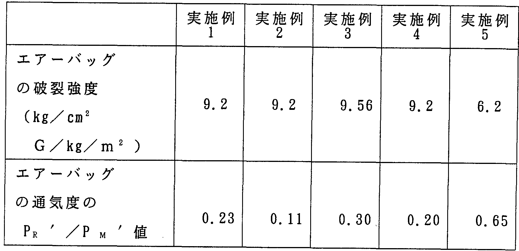
- the rupture strength of the airbag represented by the rupture internal pressure value is preferably 4.0 to 10.
- OkgZcm 2 G / kg / m 2 is preferably 4.0 to 10.
- the burst strength expressed in units of kg / cm 2 G / kg / m 2 is the burst strength per unit fabric weight (kg no m 2 ). If the burst strength is less than 4.0 kg / cm 2 G / kg / m 2 , the possibility of the air bag bursting and damaging in the event of a car collision increases, which is extremely dangerous. On the other hand, if the burst strength exceeds 10. Okg / cm 2 G / kg / m 2 , the fabric weight and the thickness become excessively large, so that the storage capacity as an airbag is reduced and the fuel efficiency of the automobile is increased. Woven for airbag of the present invention More preferably, the burst strength of the object is between 4.2 and 9.8 k / cm 2 GXkg / cm 2 .
- the airbag fabric of the present invention 200 pieces of substantially circular (diameter: about 700 mm0) pieces of cloth are collected from an arbitrary place, and the two pieces are superimposed on each other, and are subjected to double chain sewing. Sewing to form a seam with a diameter of 670 ⁇ 0, making 100 airbags of almost circular shape, filling each of them with air under a pressure of 980 Pa, The air permeability (Littleno component) is measured, and the difference P R 'between the maximum value and the minimum value is divided by the average value P M ' of all air permeability to obtain a value P R '/ P M ' time, it is good or properly this P B 'ZP M' ratio value of 0.01 to 0.5, air bags made from such fabrics exhibit a stable inner pressure, and to exhibit a uniform air permeability Can be.
- the air permeability (Littleno component) is measured, and the difference P R 'between the maximum value and the minimum value is divided by the average value P M
- ⁇ ⁇ 'and ⁇ ⁇ ' indicate the difference between the maximum value and the minimum value (P R ') and the average value (P M ') of the 100 air permeability values as described above.
- P R 'P M ' is more preferably from 0.02 to 0.48, and particularly preferably from 0.03 to 0.45.
- the woven fabric for an air bag of the present invention preferably has a seam slippage value of 0.1 to 1.0 mm in both the warp direction and the weft direction measured by applying a load of 120 kg / 5 cm. If the seam slippage value of the warp or weft is less than 0.1 dragon, the woven fabric becomes coarse and stiff, which reduces the storage capacity of the airbag, and may cause facial abrasions when colliding with the occupant's face. On the other hand, if the seam slippage value of the warp or weft exceeds 1.0 mm, the inflation gas may penetrate through the seam slippage and cause a hole or rupture in the airbag. More preferably, the seam slippage value is between 0.15 and 0.8 mm.
- the cover factor in the weft direction is preferably 1,000 to 1,280.
- Hippo of sutra —Factor is the value obtained by multiplying the square root of the fineness of the warp of the woven fabric by the warp density (this inch).
- the weft coverage factor is the value obtained by multiplying the square root of the fineness of the weft of the fabric by the weft density (this z-inch). If the background cover factor is less than 1,000, the density of the airbag fabric is too low, and the seam may slip off during inflation and the burst strength may decrease. On the other hand, if the number of cover factors exceeds 1,280, the woven fabric becomes coarse and stiff, and the storability in the airbag module may decrease.
- the cover factor is more preferably from 1,050 to 1,230, both in terms of its history.
- the polyester fabric of the present invention preferably has an air permeability of 0.2 to 9.5 liters Z dm 2 under a pressure of 500 Pa. If the air permeability under the pressure of 500 Pa is less than 0.2 liter Z dm 2 Z, the woven fabric becomes coarse and stiff and may cause facial abrasions, while the air permeability under the pressure of 500 Pa is 9.5 liters. Exceeding the Zdm 2 minutes, the inflation gas will permeate through the fabric, which could injure the occupant and cause eye injury. More preferably, the air permeability of the fabric for an air bag of the present invention at a pressure of 500 Pa is from 0.3 to 0.9 liter Zdn ⁇ min.
- a plain woven fabric of 1 Z1 and a mat woven texture of 22 are preferable, but a woven fabric having 2 1 or 2 Z 2 twill woven fabric or a Lipstop woven fabric is preferred. It may be. Further, it may have a flat / mosa fabric structure for filter cloth. However, the plain fabric structure of 11 is the most airbag that can achieve lightweight compactness and has excellent bursting strength.
- the polyester fabric of the present invention may be subjected to force rendering.
- the calendered fabric has good surface smoothness Thus, it is possible to prevent facial abrasion at the time of a face collision. In addition, since the thickness is reduced, the storability of the airbag is improved.
- the calender used for the fabric for airbags may be a normal calender, an example of which is shown in FIG.
- the calendering temperature is 180-220 ° C
- the pressure is 50-150 tons
- the speed is 4-50 mZ min.
- the calendar may be applied to only one side of the woven fabric, or may be applied to both sides. In FIG. 4, the calendar 1 has a heating roller (calender roller 1) 1, a cushion roller 2, and a pressure roller 3, into which a woven fabric or a refined woven fabric 4 is fed.
- the fabric 4 is fed by a feed roller (not shown) in the direction of the arrow and passes between the heating port 1 and the cushion roller 2. At this time, the fabric 4 is calendered and then pulled. It is picked up by a pick-up roller (not shown). In such a calendar, the position of the heating roller 1 is fixed, and the heating roller 1 is pressed in the upward direction (arrow) by the cushion roller 2 via the fabric 4, and the cushion roller 2 is pressurized. The roller 3 is pressed upward.
- the polyester filament woven fabric of the present invention may be subjected to a coating process.
- Silicon rubber and chloroprene rubber are preferably used for this coating process.
- Silicon rubber is preferred for coating of the woven fabric of the present invention because of its excellent heat resistance and coatability.
- a knife coating machine or a comma coating machine can be used for the coating process. Further, it is more preferable to apply the coating process to the woven fabric subjected to the calendering process, since a sufficient effect can be obtained even if the coating amount is reduced.
- the polyester woven fabric of the present invention is woven using the raw yarn of the polyester filament as the warp and the weft, and woven in the warp direction and the weft direction.
- a greige machine with a tensile toughness of at least 1,000 kg ⁇ % no more than 3 cm and less than 2,000 kg-% / 3 cm was produced and refined as necessary.
- the woven fabric is subjected to a shrinkage set treatment, and the shrinkage set treatment is performed so that the warp density increase rate and the weft density increase rate of the greige or woven fabric are both 5 to 25%, and the polyester filament is used.
- the above polyester filament yarn preferably has a tensile cut elongation of 9 to 18%. If the tensile elongation at break is less than 9%, the tensile toughness of the obtained woven fabric may be insufficient even after the shrinkage set treatment. On the other hand, if it exceeds 18%, the dry heat shrinkage becomes small, so that it is difficult to set the air permeability under a pressure of 500 Pa to 0.2 to 9.5 liters Zdm 2 / min.
- the tensile breaking elongation of the polyester filament raw yarn is more preferably 10 to 17%.
- the polyester filament raw yarn preferably has a dry heat shrinkage at 150 ° C of 3 to 13%. If the dry heat shrinkage is less than 3%, the shrinkage of the woven fabric is small, and it may be difficult to obtain a permeability of 0.2 to 9.5 liters Zdm 2 Z under a pressure of 500 Pa. . Also, the tensile toughness decreases. On the other hand, when the dry heat shrinkage exceeds 13%, the shrinkage of the woven fabric is too large and the woven fabric becomes coarse and stiff, and there is a risk of facial abrasion. More preferably, the dry heat shrinkage of the polyester filament yarn is 3.5 to 12%.
- polyester filament yarn monofilament fineness is used.
- the single fiber fineness is less than 1.0 de, weaving is difficult, and a woven fabric with sufficiently high tensile toughness may not be obtained.
- the single-fiber fineness exceeds 2.5 de, the storability will be reduced due to the coarse and woven fabric And may cause facial abrasions when colliding with the occupant's face.
- it may be difficult to obtain an air permeability of 0.2 to 9.5 liters Zdm 2 Z under a pressure of 500 Pa. More preferably, the single fiber fineness is 1.2 to 2.3 de.
- the total fineness of the polyester filament yarn is preferably 200 to 500 de. If the yarn denier is less than 200 de, the burst strength of the airbag may be insufficient. On the other hand, if it exceeds 500 de, the fabric weight increases, and the lightweight compactness of the airbag may become insufficient. As a denier, 250 to 450 de is more preferable.
- the polyester filament yarn used in the present invention is preferably non-twisted. If it is twisted, slippage between the yarns will be poor, so that sufficient shrinkage will not be exhibited in the woven fabric during the shrinkage set treatment, and its tensile toughness may be insufficient.
- the tensile strength of the polyester filament yarn is preferably 9.0 to 13.0 g Zde. If the tensile strength is less than 9.0 g / de, the tensile toughness of the obtained woven fabric is reduced, and as a result, the burst strength as an airbag may be insufficient. On the other hand, if it exceeds 13.0 gZde, the uniformity of the polyester filament raw yarn is reduced, and as a result, the burst strength of the obtained airbag may be insufficient. More preferably, the tensile strength of the polyester filament raw yarn is 9.2 to 12.0 gnode.
- examples of the polyester forming the polyester filament yarn include polyethylene terephthalate, polybutylene terephthalate, polyhexylene terephthalate, polyethylene naphthalate, polybutylene naphthalate, and the like.
- the intrinsic viscosity of such a polyester filament yarn is preferably 0.80 to 0.95 dl Zg.
- the intrinsic viscosity is less than 0.80 dl Z g, the tensile strength of the obtained yarn is insufficient and the mechanical strength of the woven fabric is reduced.
- the intrinsic viscosity exceeds 0.95 dl / g, the spinnability of this polymer is reduced, the quality of the original yarn is reduced, and the variability of the physical properties of the fabric is increased. More preferably, the intrinsic viscosity of the polyester is between 0.82 and 0.90 dl / g.
- the tensile toughness in the warp direction and the weft direction of the woven fabric for an airbag is not less than 1,000 kg ⁇ % 3 cm and less than 2,000 kg-% / 3 cm. If the tensile toughness in the warp or weft direction is less than 1,000 kg ⁇ 3 cm, the toughness of the greige or scoured fabric after the shrink set treatment will be insufficient. On the other hand, if it exceeds 2,000 kg-% / 3 cm, the obtained greige or scoured fabric becomes hard, excessively coarse and stiff, and shrinkage is difficult to develop.
- the tensile toughness of the greige is preferably between 1,020 and 1,950 kg ⁇ % / 3 cm, depending on the circumstances.
- the weaving is performed so that the cover factor in the warp direction and the weft direction of the airbag woven fabric is both 800 to 1,150.
- the cover factor in the warp direction or the weft direction is a value obtained by multiplying the square root of the yarn denier (thickness) of the polyester filament yarn by the weaving density of the warp or the weft (the present nonch). If the background factor of the greige is less than 800, the tensile elongation of the woven fabric will not be sufficiently increased even if the shrinkage set treatment is applied. The bursting strength of the airbag is insufficient. More preferably, both the warp and the weft have a cover factor of 830 to 1,100.
- the difference in the cover factor of the history of the greige is 5 to 100. If the difference of the cover factor in the history of the greige is less than 5, the weavability will be reduced, and it will be difficult to obtain a uniform woven fabric. On the other hand, if the difference exceeds 100, stress is concentrated on the warp or weft, and the burst strength of the obtained airbag becomes insufficient. More preferably, the difference in the history cover factor is 10 to 95.
- the cover factor may be large in either the longitude or latitude direction. However, weavability is better when the warp cover factor is 5 to 100 larger than the weft cover factor.
- the shrinkage setting treatment is performed by applying a tensile force of 10 to 500 gZcm to the woven fabric only in the warp direction in a substantially tensionless state in the weft direction.
- the value of the above tensile tension is slightly lower than the heat shrink force generated in the warp direction of the woven fabric at the surface temperature of the heated ool when the woven fabric is completely heat-set in the warp direction. Equivalent to. If the tensile tension in the warp direction is less than 10 gZcm, the woven fabric cannot be shrunk uniformly, so that the obtained fabric may have non-uniform tensile toughness.
- the tensile toughness of the resulting shrink set fabric may be insufficient. More preferably, the tensile tension in the warp direction is from 20 to 490 gZcm. In the shrinking / softening process, the woven fabric is in a substantially tension-free state in the weft direction, but the woven fabric is subjected to tensile tension in all directions due to the tensile tension due to the contact resistance with the metal surface of the heating set machine.
- shrinkage setting process may be performed before the calendar processing step, or may be performed simultaneously.
- the rate of increase in the density of the woven fabric in the warp direction or the weft direction by the shrinkage set treatment is preferably 5 to 25%. If the rate of increase in density is less than 5%, the tensile toughness of the obtained fabric is insufficient, and the burst strength of the airbag obtained therefrom may be insufficient. On the other hand, if the rate of increase in density exceeds 25%, the basis weight of the obtained woven fabric increases, and the storability of the obtained airbag may decrease. More preferably, the density increase rate in both the warp direction and the weft direction is 7 to 23%.
- the tensile cut elongation of the woven fabric is 70 to 250% in each of the warp direction and the weft direction. If the rate of increase in tensile elongation at break in the weft direction is less than 70%, the resulting fabric has insufficient tensile toughness, and the resulting airbag may have insufficient burst strength. On the other hand, if it exceeds 250%, the resulting fabric becomes coarse and stiff, and the resulting airbag may cause occupants to have facial abrasions and reduce the storage capacity of the airbag. More preferably, the rate of increase in tensile elongation at break of the woven fabric after the shrinkage set treatment is 80 to 220%.
- the tensile elongation at break is a value calculated by the following equation (1).
- Tensile cut elongation increase rate (%) ⁇ [Tensile cut elongation of fabric after shrinkage setting (%)-Tensile cut elongation of polyester filament raw yarn (%)] Z tensile yarn elongation Degree (%) ⁇ X 100
- the greige is preferably passed through a scouring process, but may be omitted for cost down purposes. Since the yarn and weaving oils can be washed and removed from the woven fabric by the greige process, it is preferable to refine the greige from the viewpoints of long-term reliability and flame retardancy of the airbag.
- FIG. 5 is a schematic diagram showing the contraction setting step.
- heating rollers 5, 6, and 7 are sequentially arranged so as to form a traveling path of the fabric 4.
- the peripheral speed of each roller is set so that the relationship of roller 5> roller 6> roller 7 holds.
- the metal roll group of this set machine has a substantial surface temperature of 1 mm.
- the shrinkage setting process is performed so that it has a temperature of 50 to 230 ° C and thereby obtains a weight shrinkage of 10 to 40%. If the actual surface temperature of the metal roll is less than 150 ° C, a sufficient shrinkage set may not be exhibited, and the tensile toughness of the obtained woven fabric may be insufficient.On the other hand, if it exceeds 230 ° C, In some cases, woven fabric may have blemishes. More preferably, the real surface temperature of the metal roll is between 155 and 220.
- the multi-stage metal roll set machine include a multi-stage metal roll set machine having 3 to 30 both-end holding metal roll groups, each metal roll being driven by a torque motor. If the number of metal rolls is less than 3, sufficient heat may not be applied to the woven fabric, so that sufficient shrinkage may not be performed. On the other hand, if the number exceeds 30, the effect saturates and the running cost increases, which is economically disadvantageous.
- the number of metal rolls is more preferably 4 to 20.
- the torque motor type multi-stage metal knurl setter can be contracted and set without holding the ears of the fabric, so that the weft direction can be largely and uniformly contracted. it can. In addition, by driving the metal roll using a torque motor, it is possible to uniformly and largely contract in the warp direction under a controlled tension. As a result, the tensile toughness of the obtained woven fabric can be made uniform and extremely large.
- the metal roll is held at both ends and is hollow, high-temperature air is injected onto the surface of all rolls, and the entire roll is controlled to a predetermined temperature. It is preferable that the surface temperature of the metal roll is controlled to a predetermined value by being stored in a disk.
- the shrinking set by the torque motor type multi-stage metal roll setting machine is performed in at least two stages of a low temperature and a high temperature, a more uniform, good and wide shrinkage can be obtained, and a woven fabric having a sufficient tensile toughness can be obtained. I like it because I can get it.
- the shrinkage is set by rapidly heating to a high temperature, the fabric may be accompanied by uneven shrinkage.
- the preferred shrink set temperature is 150 to 160 ° C as the low-temperature heating temperature accompanied by microshrinkage, and 170 to 230 ° C as the high-temperature heating temperature for real shrinking and setting.
- the most preferred method is to gradually increase the temperature in three stages from low temperature and set the shrinkage.
- the shrinkage set may be performed at one stage at a constant temperature.
- the processing speed of the shrink set is preferably 5 to 50 m / min. If this is less than 5 m / min, the processing cost may increase. On the other hand, if it exceeds 50 m, uniform shrinkage setting cannot be performed, so that a woven fabric having sufficient tensile toughness may not be obtained.
- the total contact length of the woven fabric with respect to the metal roll is 3 to 50 m and the minimum contact angle is 10 to 90 degrees.
- the total contact length refers to the sum of the lengths of the fabrics in which the fabric is in direct contact with the surface of the multi-stage roll. If the total contact length is less than 3 m, the shrinkage set may be insufficient due to insufficient heat given to the fabric. On the other hand, if it exceeds 50 m, the effect will be saturated and the running cost will increase. More preferably, the total contact length is between 3.5 and 40 m.
- the minimum contact angle is the minimum angle 0 among the angles formed by the normal line at the contact point between the fabric and the roll and the extension of the straight line constituting the fabric between the rolls as shown in Fig. 5. . If the minimum contact angle is less than 10 degrees, the contact resistance of the woven fabric on the porcelain surface becomes too large, and the shrinkage is not performed smoothly, so that the tensile toughness may be insufficient. On the other hand, if it exceeds 90 degrees, the contact resistance of the woven fabric on the roll surface becomes insufficient, so that the woven fabric shrinks abnormally and unevenly, particularly in the weft direction, and the tensile toughness of the obtained woven fabric is reduced.
- the minimum contact angle at which unevenness may occur is more preferably 15 to 85 degrees. Example
- the present invention will be described in more detail with reference to the following examples.
- the evaluation of various properties in the examples was performed according to the following methods, respectively, and the tensile elongation of the woven fabric and the tensile strength S (£) were measured by the tensile test method of the woven fabric described in JIS L-1096.
- the fabric width was 3 cm
- the test length was 20 cm
- the tensile speed was 20 ( ⁇ no.
- the tensile elongation was measured when the load reached 5 kg, which is 1% of the full scale. .
- Tensile toughness of woven fabric Using the data of S ( ⁇ ) obtained from the woven fabric tensile test, a computer was used to calculate the load curve from the load when the load reached 1% of the full scale load to the tensile elongation at break. The area between the elongation at 0 and the horizontal axis was calculated by the integration method.
- Burst strength of airbag 700 difficult dia. Two almost circular woven pieces of ⁇ are cut and superimposed, sewn to form a 670 mm diameter seam by double chain sewing, and air is blown. create a bag, therein, using a high-speed burst tester, the maximum pressure when the rupture the high pressure air in the accumulator was 40 Li Tsu torr by injecting instantaneously within 100 msec to pressure 30KgZcm 2 I asked. The value obtained by dividing the maximum internal pressure (kgZcm 2 G) by the fabric weight (kg / m 2 ) of the air bag was defined as the breaking strength (kg / cm 2 G / kg / m 2 ) of the air bag.
- Air permeability of the fabric Measured under a differential pressure of 500 Pa with an orifice having a cross-sectional area of 100 cm 2 using an air permeability meter FX3300 (manufactured by Textest, Switzerland). Air permeability P R / PM value of the fabric: the air permeability meter FX 3300 (Switzerland, Tech Sutesu preparative Inc.) was used to measure the difference pressure of 500 Pa by a 100 cm 2 cage Fi scan.
- 10 points are set at equal intervals in the width direction of the fabric, and 10 points are set at intervals of about 1 m along the length of the fabric starting from each of these points, for a total of 100 of the 100 air permeability measured (1 / dm 2 / min at 500Pa) at a point, the difference between the maximum value and the minimum value is set to [rho kappa value is divided by the average value thereof ⁇ ⁇ , P R / to calculate the P M value.
- the average value of air permeability at 10 points in the center of the fabric and the average value at 20 points in both ears of the fabric were calculated.
- P R 'ZP M ' value of airbag air permeability 100 bags of 200 pieces of woven fabric with a diameter of 700 mm are sewn to form a seam with a diameter of 670 mm0 by double chain sewing. The belt-less driver's one-seat airbags were sewn and the air permeability of each airbag was measured. The air permeability was measured at an internal pressure of 980 Pa. The P R 'ZP M ' value was calculated by dividing the difference P R 'between the maximum value and the minimum value of the air permeability (Littleno) of a total of 100 airbags by their average value PM' .
- Seam slippage value JIS L1096, except c was measured by seam slippage method of 6.21.1, using nylon 66 yarn 1260de as sewing machine thread, the load
- the slippage value was measured under a load of 0.5 kg / 5 cm 1 hour after the removal of the weight, assuming 120 kg / 5 cm.
- Fabric density and cover factor The density of the fabric in the warp and weft directions was measured with a densitometer, and the cover factor was calculated using yarn denier. For the greige machine, the yarn denier of the original yarn was used, and for the woven fabric after the shrinkage setting, the yarn denier of the yarn extracted from the woven fabric was measured and used.
- Tensile cut elongation and tensile cut strength of filament yarn Measured by the tensile test method described in JIS L1017 “Chemical fiber tire cord test method”. The twist number was 80 t / m, the test length was 25 cm, and the tensile speed was 30 cmZ.
- Dry heat shrinkage The filament yarn was shrunk at 150 ° C for 30 minutes without twisting, and calculated by the following formula.
- Intrinsic ⁇ 0.6 g of polyester filament yarn was dissolved in 50 ml of 0-chlorophenol to form a solution, and measured at 35 ° C.
- the tensile filament elongation is 13.5%
- the dry heat shrinkage at 150 ° C is 6.5%
- the polyester filament yarn of 420 de / 249 filament is used.
- Teijin Ltd. was prepared and woven in an untwisted state using a water jet room into the plain fabrics shown in Table 2 (cover factor of the greige: 1,086, 1,045, 41) ).
- the greige was scoured and dried, and subjected to a shrinkage setting while applying tension in the warp direction by a multi-stage roll set machine under the conditions shown in Table 4, and a force bar factor was applied to the warp 1,231,
- a polyester fabric having a weft of 1,189, a weft difference of 42, a basis weight shrinkage of 22.0, an elongation of elongation at break of 202% and a weft of 190% was obtained.
- the surface temperature of the metal roll of the above setting machine was obtained by performing the two-step setting of 155 ° C in the first half at 155 ° C for about 1 minute and the second half at 190 ° C for about 1.5 minutes c.
- Example 1 Using the polyester filament yarns shown in Table 1, the plain weaves shown in Tables 2 and 3 were woven in the same manner as in Example 1, and the multi-stage metal rolls (rolls were at the temperatures shown in Tables 4 and 5) were used. Ten fabrics) or a tenter method was used to set the shrinkage, and fabrics shown in Tables 6 and 7 were created. Some fabrics were calendered. For these woven fabrics, the tensile elongation ⁇ was measured and a load-elongation curve was created. The load-elongation curves of Example 2 are shown in FIGS. 2 and 3, and the load-elongation curves of Comparative Example 1 are shown in FIGS. 3A and 3B.
- Tables 8 and 9 show the results of evaluating the physical properties of the woven fabrics of Examples 1 to 5 and Comparative Examples 1 to 3 and the burst strength of the airbag.
- the shrinkage was set in one stage using a multistage metal roll (10 rolls) at 200 ° C.
- the shrinkage set was performed in one stage using a tenter at 200 ° C. In these cases, the feed speed of the greige during the contraction set processing was slightly increased as compared with the first embodiment.
- Example 1 Example 2
- Example 3 Example 4
- Example 5 Single side, 180 ° C Single side, 180 ° C Single side, 180 ° C
- the fabric for a high-performance airbag of the present invention satisfies all of the above-mentioned performances (1) to (3) required when the airbag is formed, and the airbag obtained therefrom is safe. It is excellent in practicality.
Description


Claims
Priority Applications (4)
| Application Number | Priority Date | Filing Date | Title |
|---|---|---|---|
| DE1994619729 DE69419729T2 (de) | 1993-10-13 | 1994-10-13 | Gewebe für hochleistungs-luftsack und verfahren zu dessen herstellung |
| US08/454,203 US5540965A (en) | 1993-10-13 | 1994-10-13 | Woven fabric for high performance air bags and process for producing same |
| EP19940929655 EP0682136B1 (en) | 1993-10-13 | 1994-10-13 | Fabric for a high performance air bag and method for producing the same |
| JP51159695A JP2944220B2 (ja) | 1993-10-13 | 1994-10-13 | 高性能エアーバッグ用織物およびその製造方法 |
Applications Claiming Priority (6)
| Application Number | Priority Date | Filing Date | Title |
|---|---|---|---|
| JP5/278885 | 1993-10-13 | ||
| JP27888593 | 1993-10-13 | ||
| JP14703994 | 1994-06-07 | ||
| JP6/147038 | 1994-06-07 | ||
| JP14703894 | 1994-06-07 | ||
| JP6/147039 | 1994-06-07 |
Publications (1)
| Publication Number | Publication Date |
|---|---|
| WO1995010652A1 true WO1995010652A1 (fr) | 1995-04-20 |
Family
ID=27319284
Family Applications (1)
| Application Number | Title | Priority Date | Filing Date |
|---|---|---|---|
| PCT/JP1994/001719 WO1995010652A1 (fr) | 1993-10-13 | 1994-10-13 | Tissu pour coussin gonflable de securite de haute performance et son procede de production |
Country Status (5)
| Country | Link |
|---|---|
| US (1) | US5540965A (ja) |
| EP (1) | EP0682136B1 (ja) |
| JP (1) | JP2944220B2 (ja) |
| DE (1) | DE69419729T2 (ja) |
| WO (1) | WO1995010652A1 (ja) |
Cited By (6)
| Publication number | Priority date | Publication date | Assignee | Title |
|---|---|---|---|---|
| JP2007038693A (ja) * | 2005-07-29 | 2007-02-15 | Seiren Co Ltd | 高気密エアバッグの製造方法 |
| CN102168333A (zh) * | 2010-02-25 | 2011-08-31 | 东丽纤维研究所(中国)有限公司 | 一种安全气囊用织物 |
| WO2012120985A1 (ja) * | 2011-03-10 | 2012-09-13 | 東洋紡績株式会社 | エアバッグ |
| JP2012524845A (ja) * | 2009-04-23 | 2012-10-18 | コーロン インダストリーズ インク | エアバッグ用ポリエステル織物及びその製造方法 |
| WO2017057300A1 (ja) * | 2015-09-30 | 2017-04-06 | セーレン株式会社 | エアバッグ用織物およびエアバッグ |
| JPWO2017010458A1 (ja) * | 2015-07-13 | 2018-04-19 | 東レ株式会社 | エアバッグ用基布、エアバッグおよびエアバッグ用基布の製造方法 |
Families Citing this family (30)
| Publication number | Priority date | Publication date | Assignee | Title |
|---|---|---|---|---|
| JP3475596B2 (ja) * | 1995-08-01 | 2003-12-08 | チッソ株式会社 | 耐久親水性繊維、布状物及び成形体 |
| JP2001507083A (ja) * | 1996-10-21 | 2001-05-29 | プリシジョン・ファブリックス・グループ・インコーポレーテッド | 平衡した弾性係数と不平衡な構造とを備えた布 |
| US6632754B1 (en) * | 1997-01-16 | 2003-10-14 | Precision Fabrics Group, Inc. | Unbalanced twill weave fabric and airbag device |
| US6473948B1 (en) * | 1997-04-17 | 2002-11-05 | Milliken & Company | Air bag fabric possessing improved packed volume characteristics |
| US6022817A (en) * | 1997-06-06 | 2000-02-08 | E. I. Du Pont De Nemours And Company | Fabric for airbag |
| US6402187B1 (en) | 1998-10-06 | 2002-06-11 | Milliken & Company | Airbag structure |
| DE19945880A1 (de) * | 1999-09-24 | 2001-03-29 | Berger Seiba Technotex Verwaltungs Gmbh & Co | Verfahren zur Herstellung von Geweben |
| US6444594B1 (en) * | 1999-11-10 | 2002-09-03 | Milliken & Company | Airbag coatings providing improved thermal resistance |
| TWI230213B (en) * | 2000-08-17 | 2005-04-01 | Toray Industries | Base fabric for non-coated air bags, and fibers for air bags |
| US6672617B1 (en) | 2000-09-08 | 2004-01-06 | Milliken & Company | Yarn, airbag and method |
| WO2002081799A2 (en) * | 2001-02-22 | 2002-10-17 | Milliken & Company | Low abrasion elastomeric fabric |
| KR100431507B1 (ko) * | 2001-09-07 | 2004-05-14 | 주식회사 경인 | 뒤틀림이 적은 공기 주입식 보트원단용 직물제직방법,이에 따라 제조된 직물 및 이를 포함하는 보트 제조용 원단 |
| US7226079B2 (en) | 2002-05-10 | 2007-06-05 | Lear Corporation | Air bag assembly with two piece air bag housing |
| US20040119267A1 (en) * | 2002-12-19 | 2004-06-24 | Lear Corporation | Natural fiber tether for an airbag system |
| DE60312950T2 (de) * | 2002-12-26 | 2007-12-20 | Toyo Boseki K.K. | Gaseinleitungs- und -verteilungschlauch |
| CN100415574C (zh) * | 2003-05-15 | 2008-09-03 | 因温斯特技术公司 | 充气袋用聚酯纤丝机织织物 |
| US20040229538A1 (en) * | 2003-05-15 | 2004-11-18 | Love Franklin S. | Woven stretch fabrics and methods of making same |
| KR100751545B1 (ko) | 2005-11-15 | 2007-08-23 | 인비스타 테크놀로지즈 에스.에이.알.엘. | 폴리에스테르 단섬유로 직조된 에어백용 직물 |
| US7581568B2 (en) * | 2006-02-07 | 2009-09-01 | International Textile Group, Inc. | Water jet woven air bag fabric made from sized yarns |
| KR101295696B1 (ko) | 2009-12-24 | 2013-08-14 | 주식회사 효성 | 에어백용 폴리에틸렌테레프탈레이트 섬유 및 이를 이용한 직물 |
| EP2518195B1 (en) * | 2009-12-24 | 2018-10-31 | Hyosung Advanced Materials Corporation | Polyethylene terephthalate fiber for air-bags and textiles made from same |
| EP2554722B1 (en) | 2010-03-29 | 2021-02-24 | Kolon Industries, Inc. | Polyester yarn and method for manufacturing same |
| KR101553017B1 (ko) | 2010-06-28 | 2015-09-15 | 코오롱인더스트리 주식회사 | 에어백용 폴리에스테르 원사 및 그의 제조방법 |
| CN103109003B (zh) * | 2010-09-17 | 2015-01-14 | 可隆工业株式会社 | 聚酯纱线及其制备方法 |
| US10480107B2 (en) * | 2014-03-18 | 2019-11-19 | Schroth Safety Products, Llc | Method of making a flame resistant airbag suitable for use in aviation applications |
| AU2016297915B2 (en) * | 2015-07-29 | 2019-04-18 | Gates Corporation | Synchronous belt with tough fabric |
| MX2018005538A (es) | 2015-11-06 | 2018-11-09 | Invista Textiles Uk Ltd | Tela de baja permeabilidad y alta resistencia y metodos para hacer la misma. |
| CA3060311C (en) | 2017-05-02 | 2022-05-24 | Invista Textiles (U.K.) Limited | Low permeability and high strength woven fabric and methods of making the same |
| BR112020006305A2 (pt) | 2017-09-29 | 2020-09-24 | Invista Textiles (U.K.) Limited | airbags e métodos para a produção de airbags |
| EP3854919B1 (en) * | 2018-09-19 | 2023-07-26 | Toray Industries, Inc. | Non-coated base fabric for airbag, airbag, and manufacturing method of non-coated base fabric for airbag |
Citations (3)
| Publication number | Priority date | Publication date | Assignee | Title |
|---|---|---|---|---|
| JPH042835A (ja) * | 1990-04-17 | 1992-01-07 | Stern & Stern Ind Inc | 低い透過性の織布及びその製造方法 |
| JPH04214437A (ja) * | 1990-02-12 | 1992-08-05 | Hoechst Ag | エアバッグ用布帛 |
| JPH04262938A (ja) * | 1991-02-19 | 1992-09-18 | Teijin Ltd | エアーバッグ |
Family Cites Families (6)
| Publication number | Priority date | Publication date | Assignee | Title |
|---|---|---|---|---|
| DE8714595U1 (ja) * | 1987-11-03 | 1988-01-28 | Bloch, Klaus, 5205 St Augustin, De | |
| US4977016B1 (en) * | 1988-10-28 | 1998-03-03 | Stern & Stern Ind Inc | Low permeability fabric and method of making same |
| JPH03167312A (ja) * | 1989-11-28 | 1991-07-19 | Toray Ind Inc | 衝撃吸収エアバッグ用ポリエステル繊維 |
| US5236775A (en) * | 1990-02-12 | 1993-08-17 | Hoechst Aktiengesellschaft | Fabric for airbag |
| DE59209644D1 (de) * | 1991-07-16 | 1999-04-15 | Akzo Nobel Nv | Technische Gewebe mit gezielt eingestellter Luftdurchlässigkeit und hoher Alterungsbeständigkeit sowie Verfahren zu deren Herstellung |
| JPH05214632A (ja) * | 1992-01-31 | 1993-08-24 | Unitika Ltd | エアーバツグ用シート |
-
1994
- 1994-10-13 WO PCT/JP1994/001719 patent/WO1995010652A1/ja not_active Application Discontinuation
- 1994-10-13 US US08/454,203 patent/US5540965A/en not_active Expired - Lifetime
- 1994-10-13 EP EP19940929655 patent/EP0682136B1/en not_active Revoked
- 1994-10-13 DE DE1994619729 patent/DE69419729T2/de not_active Revoked
- 1994-10-13 JP JP51159695A patent/JP2944220B2/ja not_active Expired - Fee Related
Patent Citations (3)
| Publication number | Priority date | Publication date | Assignee | Title |
|---|---|---|---|---|
| JPH04214437A (ja) * | 1990-02-12 | 1992-08-05 | Hoechst Ag | エアバッグ用布帛 |
| JPH042835A (ja) * | 1990-04-17 | 1992-01-07 | Stern & Stern Ind Inc | 低い透過性の織布及びその製造方法 |
| JPH04262938A (ja) * | 1991-02-19 | 1992-09-18 | Teijin Ltd | エアーバッグ |
Non-Patent Citations (1)
| Title |
|---|
| See also references of EP0682136A4 * |
Cited By (14)
| Publication number | Priority date | Publication date | Assignee | Title |
|---|---|---|---|---|
| JP4660312B2 (ja) * | 2005-07-29 | 2011-03-30 | セーレン株式会社 | 高気密エアバッグの製造方法 |
| JP2007038693A (ja) * | 2005-07-29 | 2007-02-15 | Seiren Co Ltd | 高気密エアバッグの製造方法 |
| US8822358B2 (en) | 2009-04-23 | 2014-09-02 | Kolon Industries, Inc. | Polyester fabrics for airbag and preparation method thereof |
| JP2012524845A (ja) * | 2009-04-23 | 2012-10-18 | コーロン インダストリーズ インク | エアバッグ用ポリエステル織物及びその製造方法 |
| CN102168333B (zh) * | 2010-02-25 | 2013-10-02 | 东丽纤维研究所(中国)有限公司 | 一种安全气囊用织物 |
| CN102168333A (zh) * | 2010-02-25 | 2011-08-31 | 东丽纤维研究所(中国)有限公司 | 一种安全气囊用织物 |
| WO2012120985A1 (ja) * | 2011-03-10 | 2012-09-13 | 東洋紡績株式会社 | エアバッグ |
| JP2012188006A (ja) * | 2011-03-10 | 2012-10-04 | Toyobo Co Ltd | エアバッグ |
| US8919810B2 (en) | 2011-03-10 | 2014-12-30 | Toyobo Co., Ltd. | Air bag |
| JPWO2017010458A1 (ja) * | 2015-07-13 | 2018-04-19 | 東レ株式会社 | エアバッグ用基布、エアバッグおよびエアバッグ用基布の製造方法 |
| WO2017057300A1 (ja) * | 2015-09-30 | 2017-04-06 | セーレン株式会社 | エアバッグ用織物およびエアバッグ |
| JPWO2017057300A1 (ja) * | 2015-09-30 | 2018-07-19 | セーレン株式会社 | エアバッグ用織物およびエアバッグ |
| US20180281737A1 (en) * | 2015-09-30 | 2018-10-04 | Seiren Co., Ltd. | Fabric for air bag and air bag |
| US10737656B2 (en) | 2015-09-30 | 2020-08-11 | Seiren Co., Ltd. | Fabric for air bag and air bag |
Also Published As
| Publication number | Publication date |
|---|---|
| JP2944220B2 (ja) | 1999-08-30 |
| DE69419729T2 (de) | 1999-12-30 |
| EP0682136B1 (en) | 1999-07-28 |
| US5540965A (en) | 1996-07-30 |
| EP0682136A1 (en) | 1995-11-15 |
| DE69419729D1 (de) | 1999-09-02 |
| EP0682136A4 (en) | 1996-01-17 |
Similar Documents
| Publication | Publication Date | Title |
|---|---|---|
| WO1995010652A1 (fr) | Tissu pour coussin gonflable de securite de haute performance et son procede de production | |
| CN107709641B (zh) | 安全气囊用基布、安全气囊及安全气囊用基布的制造方法 | |
| JP3855775B2 (ja) | コ−トエアバッグ用基布 | |
| KR102179158B1 (ko) | 에어백용 기포 및 그의 제조 방법 | |
| JP2012524845A (ja) | エアバッグ用ポリエステル織物及びその製造方法 | |
| JP3457739B2 (ja) | ノンコートサイドエアーバッグ用織物 | |
| JP3871103B2 (ja) | エアバッグ用基布およびエアバッグ | |
| EP3279378B1 (en) | Airbag-use woven fabric and airbag | |
| JP3089155B2 (ja) | エアーバッグ用ポリエステルフィラメント織物 | |
| JP4423853B2 (ja) | エアバッグ用基布およびエアバッグ | |
| JPH082359A (ja) | 高滑脱抵抗性エアーバッグ用織物 | |
| JP3849818B2 (ja) | エアバッグ用基布およびエアバッグとその製造方法 | |
| JP2002069790A (ja) | エアバッグ用基布およびエアバッグ | |
| EP4130364A1 (en) | Base cloth for material and manufacturing method therefor | |
| JP3849812B2 (ja) | エアバッグ用基布およびエアバッグ | |
| JP3421135B2 (ja) | 破裂強度と難燃性の改良された柔軟性ポリエステルエアーバッグ用織物の製造方法 | |
| JPH08199449A (ja) | ノンコートエアバッグ用基布およびエアバッグ | |
| CN113302349B (zh) | 安全气囊用基布和安全气囊用基布的制造方法 | |
| JPH09105047A (ja) | ノンコートエアーバッグ用織物 | |
| JP2007023411A (ja) | エアバッグ用織物およびエアバッグならびにエアバッグ用織物の製造方法 | |
| JP2001032145A (ja) | ノンコートエアバッグ用織物 | |
| JPH108344A (ja) | 均一な通気度を有するエアーバッグ用フィルタークロスおよびその製造方法 | |
| JP3033350U (ja) | エアーバッグ・システム搭載パラグライダー | |
| JPH07186857A (ja) | エアバッグ用基布 | |
| JPH07119030A (ja) | エアーバッグ用ポリエステルカレンダ織物およびその製造法 |
Legal Events
| Date | Code | Title | Description |
|---|---|---|---|
| AK | Designated states |
Kind code of ref document: A1 Designated state(s): JP US |
|
| AL | Designated countries for regional patents |
Kind code of ref document: A1 Designated state(s): AT BE CH DE DK ES FR GB GR IE IT LU MC NL PT SE |
|
| WWE | Wipo information: entry into national phase |
Ref document number: 1994929655 Country of ref document: EP |
|
| WWE | Wipo information: entry into national phase |
Ref document number: 08454203 Country of ref document: US |
|
| 121 | Ep: the epo has been informed by wipo that ep was designated in this application | ||
| WWP | Wipo information: published in national office |
Ref document number: 1994929655 Country of ref document: EP |
|
| WWG | Wipo information: grant in national office |
Ref document number: 1994929655 Country of ref document: EP |
|
| WWW | Wipo information: withdrawn in national office |
Ref document number: 1994929655 Country of ref document: EP |