WO1995012938A1 - Variable rate signal transmission in a spread spectrum communication system using coset coding - Google Patents
Variable rate signal transmission in a spread spectrum communication system using coset coding Download PDFInfo
- Publication number
- WO1995012938A1 WO1995012938A1 PCT/US1994/012540 US9412540W WO9512938A1 WO 1995012938 A1 WO1995012938 A1 WO 1995012938A1 US 9412540 W US9412540 W US 9412540W WO 9512938 A1 WO9512938 A1 WO 9512938A1
- Authority
- WO
- WIPO (PCT)
- Prior art keywords
- signal
- coset
- combining
- signals
- modulated
- Prior art date
Links
Classifications
-
- H—ELECTRICITY
- H04—ELECTRIC COMMUNICATION TECHNIQUE
- H04J—MULTIPLEX COMMUNICATION
- H04J13/00—Code division multiplex systems
- H04J13/10—Code generation
- H04J13/12—Generation of orthogonal codes
-
- H—ELECTRICITY
- H04—ELECTRIC COMMUNICATION TECHNIQUE
- H04J—MULTIPLEX COMMUNICATION
- H04J13/00—Code division multiplex systems
-
- H—ELECTRICITY
- H04—ELECTRIC COMMUNICATION TECHNIQUE
- H04B—TRANSMISSION
- H04B1/00—Details of transmission systems, not covered by a single one of groups H04B3/00 - H04B13/00; Details of transmission systems not characterised by the medium used for transmission
- H04B1/69—Spread spectrum techniques
- H04B1/707—Spread spectrum techniques using direct sequence modulation
-
- H—ELECTRICITY
- H04—ELECTRIC COMMUNICATION TECHNIQUE
- H04L—TRANSMISSION OF DIGITAL INFORMATION, e.g. TELEGRAPHIC COMMUNICATION
- H04L1/00—Arrangements for detecting or preventing errors in the information received
- H04L1/08—Arrangements for detecting or preventing errors in the information received by repeating transmission, e.g. Verdan system
-
- H—ELECTRICITY
- H04—ELECTRIC COMMUNICATION TECHNIQUE
- H04L—TRANSMISSION OF DIGITAL INFORMATION, e.g. TELEGRAPHIC COMMUNICATION
- H04L27/00—Modulated-carrier systems
- H04L27/32—Carrier systems characterised by combinations of two or more of the types covered by groups H04L27/02, H04L27/10, H04L27/18 or H04L27/26
- H04L27/34—Amplitude- and phase-modulated carrier systems, e.g. quadrature-amplitude modulated carrier systems
- H04L27/3405—Modifications of the signal space to increase the efficiency of transmission, e.g. reduction of the bit error rate, bandwidth, or average power
- H04L27/3416—Modifications of the signal space to increase the efficiency of transmission, e.g. reduction of the bit error rate, bandwidth, or average power in which the information is carried by both the individual signal points and the subset to which the individual points belong, e.g. using coset coding, lattice coding, or related schemes
- H04L27/3427—Modifications of the signal space to increase the efficiency of transmission, e.g. reduction of the bit error rate, bandwidth, or average power in which the information is carried by both the individual signal points and the subset to which the individual points belong, e.g. using coset coding, lattice coding, or related schemes in which the constellation is the n - fold Cartesian product of a single underlying two-dimensional constellation
-
- H—ELECTRICITY
- H04—ELECTRIC COMMUNICATION TECHNIQUE
- H04J—MULTIPLEX COMMUNICATION
- H04J13/00—Code division multiplex systems
- H04J13/0007—Code type
- H04J13/0022—PN, e.g. Kronecker
-
- H—ELECTRICITY
- H04—ELECTRIC COMMUNICATION TECHNIQUE
- H04J—MULTIPLEX COMMUNICATION
- H04J13/00—Code division multiplex systems
- H04J13/0007—Code type
- H04J13/004—Orthogonal
Definitions
- the present invention relates to communication systems utilizing spread spectrum signals, and, more particularly, to a novel and improved method and apparatus for communicating information in a spread spectrum communication system.
- the information signal In transmitting an information signal from a source location over a communication channel, the information signal is first converted into a form suitable for efficient transmission over the channel. Conversion, or modulation, of the information signal involves varying a parameter of a carrier wave on the basis of the information signal in such a way that the spectrum of the resulting modulated carrier is confined within the channel bandwidth. At the user location the original message signal is replicated from a version of the modulated carrier received subsequent to propagation over the channel. Such replication is generally achieved by using an inverse of the modulation process employed by the source transmitter.
- Modulation also facilitates multiplexing, i.e. , the simultaneous transmission of several signals over a common channel.
- Multiplexed communication systems will generally include a plurality of remote subscriber units requiring intermittent service of relatively short duration rather than continuous access to the communication channel.
- Systems designed to enable communication over brief periods of time with a set of subscriber units have been termed multiple access communication systems.
- a particular type of multiple access communication system is known as a spread spectrum system.
- the modulation technique utilized results in a spreading of the transmitted signal over a wide frequency band within the communication channel.
- One type of multiple access spread spectrum system is a code division multiple access (CDMA) modulation system.
- CDMA code division multiple access
- Other multiple access communication system techniques such as time division multiple access (TDMA).
- communication in a CDMA system between a pair of locations is achieved by spreading each transmitted signal over the channel bandwidth by using a unique user spreading code.
- Specific transmitted signals are extracted from the communication channel by despreading the composite signal energy in the communication channel with the user spreading code associated with the transmitted signal to be extracted.
- spread spectrum communication systems it has been desired to allow various types of user channels (e.g. , voice, facsimile, or high-speed data) to operate at different data rates.
- user channels e.g. , voice, facsimile, or high-speed data
- These systems have typically been designed to have channels operative at a nominal data rate, and also to have reduced data rate traffic channels for providing more traffic data capacity.
- reduced data rate traffic channels for providing more traffic data capacity.
- increasing traffic capacity by using reduced data rate channels lengthens the time required for data transmission.
- the implementation of CDMA techniques in spread spectrum communication systems using orthogonal PN code sequences reduces mutual interference between users, thereby allowing higher capacity and better performance.
- the present invention provides an improved system and method for communicating information over in-phase (I) and quadrature phase (Q) communication channels in a CDMA spread spectrum communication system.
- an input information signal is transmitted over either an I or Q communication channel using a direct sequence spread spectrum communication signal.
- the information signal is initially divided into first and second subsignals, which are respectively provided to first and second coset-encoding networks.
- the first coset-encoding combines the first subsignal with a first coset code
- the second coset-encoding network combines the second subsignal with a second coset code orthogonal to the first coset code.
- the first and second coset-encoding networks are operative to produce first and second coset-encoded signals, respectively.
- a composite coset-encoded signal formed from the first and second coset-encoded signals is then modulated by an orthogonal function signal to provide a first modulated signal.
- In-phase pseudorandom noise (PN I ) and quadrature phase pseudorandom noise (PN Q ) signals of predetermined PN codes are used for spreading the first modulated signal over either the I or Q communication channel, respectively.
- the PN I signal may be combined with the first modulated signal to provide an I-channel modulation signal for transmission to a receiver via the I communication channel.
- the receiver is operative to produce an estimate of the input information signal on the basis of the modulated carrier signal received over either the I or Q communication channel.
- the received signal is first demodulated using the orthogonal function signal.
- the demodulated signal is then decorrelated using a despreading PN signal, with the resultant projection signals being provided to a phase rotator.
- the phase rotator operates to provide an estimate of the composite coset-encoded signal based on the projection signals and a received pilot signal. Estimates of the first and second subsignals are made by performing a further decorrelation based upon the orthogonality of the first and second coset codes.
- FIG. 1 shows a block diagram of a conventional spread spectrum transmitter.
- FIG. 2 shows a block diagram of a preferred embodiment of a spread spectrum transmitter disposed to transmit I-channel and Q-channel information signals.
- FIG. 3 shows a block diagrammatic representation of an I-channel coset encoding network operative to encode information signals in accordance with the invention.
- FIG. 4 is a block diagrammatic representation of a rate 1/p coset encoder of a type suitable for inclusion in the coset encoding network of FIG. 3.
- FIG. 5 shows a block diagrammatic representation of a pair of I-channel and Q-channel coset encoding networks utilized in a preferred embodiment of the invention to transmit data at four times a nominal data rate.
- FIG. 6 shows a block diagrammatic representation of a pair of I-channel and Q-channel 1/4 rate coset encoding networks utilized in a preferred embodiment of the invention to transmit data at eight times the nominal rate.
- FIG. 7 shows a block diagrammatic representation of a coset encoding network utilized in a preferred embodiment to transmit data at a rate equivalent to one-half of the nominal rate.
- FIG. 8 shows a block diagrammatic representation of a coset encoding network utilized in a preferred embodiment to transmit data at a rate equivalent to one-fourth of the nominal rate.
- FIG. 9 depicts a pilot generation network for providing I and Q channel pilot sequences.
- FIG. 10 shows an exemplary implementation of an RF transmitter incorporated within a preferred embodiment of the invention.
- FIG. 12 is a block diagram of an exemplary diversity receiver disposed to receive the RF signal energy transmitted over the I and Q communication channels.
- FIG. 13 is a block diagram of a receiver finger included within the diversity receiver of FIG. 12 designed to process signal energy received over a selected transmission path.
- FIG. 14 provides a more detailed representation of the selected receiver finger illustrated in FIG. 13. DESCRIPTION OF THE PREFERRED EMBODIMENT
- FIG. 1 there is shown a spread spectrum transmitter such as is described in U.S. Patent No. 5, 103,459, issued 1992, entitled “SYSTEM AND METHOD FOR GENERATING SIGNAL WAVEFORMS IN A CDMA CELLULAR TELEPHONE SYSTEM", which is assigned to the assignee of the present invention, and which is herein incorporated by reference.
- data bits 100 consisting of, for example, voice converted to data by a vocoder, are supplied to an encoder 102 where the bits are convolutional encoded with code symbol repetition in accordance with the input data rate.
- code symbol repetition dictates that encoder 102 repeat the input data bits 100 in order to create a repetitive data stream at a bit rate which matches the operative rate of encoder 102.
- the encoded data is then provided to interleaver 104 where it is convolutional interleaved.
- the interleaved symbol data is output from interleaver 104 at an exemplary rate of 19.2 ksps to an input of exclusive-OR gate 106.
- the interleaved data symbols are scrambled to provide greater security in transmissions over the channel.
- Scrambling of the voice channel signals may be accomplished by pseudonoise (PN) coding the interleaved data with a PN code specific to an intended recipient subscriber unit.
- PN scrambling may be provided by the PN generator 108 using a suitable PN sequence or encryption scheme.
- the PN generator 108 will typically include a long PN generator for producing a unique PN code at a fixed PN chip rate of 1.2288 MHz.
- This PN code is then passed through a decimator, with the resulting 19.2 kilo-symbol per second (ksps) scrambling sequence being supplied to the other input of exclusive-OR 106 in accordance with subscriber unit identification information provided thereto.
- the output of exclusive-OR 106 is then provided to one input of exclusive-OR 1 10.
- exclusive-OR gate 1 10 is connected to a Walsh waveform generator 112.
- Walsh generator 1 12 generates a Walsh waveform assigned to the data channel over which information is being transmitted.
- the Walsh waveform provided by generator 1 12 is selected from a set of 64 Walsh waveforms, each having a length of length 64 Walsh chips.
- the 64 orthogonal waveforms correspond to entries within a 64 by 64 Hadamard matrix wherein a particular Walsh waveform is defined by a row or column of the matrix.
- the scrambled symbol data and Walsh waveform are exclusive-OR 'ed by exclusive-OR gate 1 10 with the result provided as an input to both of the exclusive-OR gates 1 14 and 1 16.
- Exclusive-OR gate 1 14 also receives a PN I signal, while the other input of exclusive-OR gate 1 16 receives a PN C , signal.
- the PN I and PN C , signals are pseudorandom noise sequences typically corresponding to a particular area, i.e. , cell, covered by the CDMA system and relate respectively to in-phase (I) and quadrature phase (Q) communication channels.
- the PN I and PN C , signals are respectively exclusive-OR'ed with the output of exclusive-OR gate 1 10 so as to further spread the user data prior to transmission.
- the resulting I-channel code spread sequence 122 and Q-channel code spread sequence 126 are used to bi-phase modulate a quadrature pair of sinusoids. The modulated sinusoids are summed, bandpass filtered, shifted to an RF frequency, and again filtered and amplified prior to being radiated via an antenna to complete transmission over the communication channel.
- the present invention enables spread spectrum transmission of an information signal at higher than the nominal rate, or of transmission of a plurality of information signals at lower than the nominal rate, using common encoding, interleaving and modulation rates.
- FIG. 2 shows a block diagram of a preferred embodiment of a spread spectrum transmitter 150 of the invention disposed to transmit an input information signal S IN of data rate kR b , where k is an integer constant and R b denotes a nominal transmitter data (i.e. , bit) rate.
- R b is defined as being equivalent to the product of the PN chip rate and the convolutional encoding code rate, divided by the number of Walsh chips per symbol of the Walsh waveform.
- a nominal transmitter data rate R b of 9.6 kbps is set by utilizing a set of modulation parameters in which the PN chip rate is selected to be 1.2288 MHz, the convolutional code rate is a rate 1/2 code, and the Walsh waveform symbol length is set at 64. It is a feature of the present invention that the transmitter 150 may be employed to transmit information signals having data rates greater than or equal to the nominal rate without adjustment of the values of the foregoing modulation parameters. As is described hereinafter, the present invention also provides a technique for transmitting a plurality of information signals of data rates lower than the nominal rate without requiring corresponding modulation parameter adjustment.
- the input information bit sequence S IN may consist of, for example, voice converted to a stream of data bits by a vocoder. As is indicated by
- the input data stream is supplied to an encoding and interleaving network 160.
- the network 160 convolutional encodes the information bit sequence S IN , with the encoded data then being interleaved and output from the network 160 as an encoded and interleaved symbol stream S INT .
- the symbol stream S INT is supplied to a demultiplexer 170 at a symbol rate of 2kR b
- the demultiplexer 170 transforms the symbol stream S INT into a set of k symbol substreams (A(1), A(2), ... A(k) ⁇ each at a rate of 2R b , by routing successive symbols S INT.i to successive ones of the substreams ⁇ A(1 ), A(2), ... A(k) ⁇ .
- the first k/2 symbol substreams are provided to an I-channel coset-encoding network 180, while the remaining k/2 symbol substreams are provided to a Q-channel coset-encoding network 190.
- the coset-encoded symbol substreams within the networks 180 and 190 are then summed into I-channel and Q-channel composite symbol streams I c and Q c , respectively.
- a pair of identical Walsh waveforms are provided to I-channel and Q-channel modulation and spreading networks 200 and 205 by a Walsh waveform generator 210.
- the Walsh waveforms are used within the networks 200 and 205 to modulate the I-channel and Q-channel composite symbol streams I c and Q c .
- PN spreading signals are also respectively provided to the modulation and spreading networks 200 and 205 by PN I and PN Q sequence generators 215 and 220.
- the PN I sequence is used to spread the composite symbol stream I c into an I-channel code spread sequence S I .
- the PN Q sequence is utilized by the network 205 to spread the composite symbol stream Q c into a Q-channel code spread sequence S Q .
- the resultant I-channel and Q-channel code spread sequences S I and S Q are used to bi-phase modulate a quadrature pair of sinusoids generated within an RF transmitter 225.
- the modulated sinusoids will generally be summed, bandpass filtered, shifted to an RF frequency, and amplified prior to being radiated via an antenna over I and Q communication channels.
- FIG. 3 shows a block diagrammatic representation of the I-channel coset encoding network 180, it being understood that the Q-channel coset encoding network may be realized in a substantially identical manner.
- the encoding network 180 includes a plurality of coset encoders 250 to which are supplied the k/2 symbol substreams from the demultiplexer 170.
- the encoders 250 are operative to generate k/2 sequences ⁇ a( 1 ), a(2), ... a(k/2) ⁇ in which
- each symbol within the symbol substreams ⁇ A(1), A(2), ... A(k) ⁇ is repeated "p" times, with the "p th " repeated symbol being exclusive-OR'ed with the p th coefficient of the corresponding coset code.
- This operation has been characterized by those skilled in the art as encoding using a "rate 1/p repetition coset code".
- FIG. 4 is a block diagrammatic representation of a rate 1/p coset encoder 300 disposed to use a coset code C to encode an input symbol stream R s into an output coset-encoded symbol stream R s.enc , where C E ⁇ c 1 , c 2 , ... , c p ⁇ .
- the coset encoder includes a demulitplexer 305 for providing each symbol r t included within the symbol stream R s to a set of p exclusive-OR gates 310.
- Each of the symbols r i is exclusive-OR' ed with one of the coset code coefficients c p , with the result being supplied to a p: 1 multiplexer 315.
- the multiplexer 315 then produces the coset-encoded symbol stream R s . enc , where R s . enc ⁇ ⁇ r 1 ⁇ c 1 , r 1 ⁇ c 2 , .... r 1 ⁇ c p , r 2 ⁇ c 1 , r 2 ⁇ c 2 , ...r 2 ⁇ c p , ..., r i ⁇ c p ,.. ⁇ . More generally, for each symbol r i the rate 1/p coset encoder produces a sequence,
- A(2), ...A(k) ⁇ and the coset codes S 1 , S 2 , ... , S k/2 are composed of the logical values 0 and 1 , as are the sequences ⁇ a(1), a(2), ... a(k/2) ⁇ generated by the coset encoders
- sequences ⁇ a( 1), a(2), ... a(k/2) ⁇ are converted to an integer, i.e. , ⁇ 1 , representation by a set of binary-to-integer conversion circuits 260 as follows:
- the sequence I c is then created by combining the outputs from the conversion circuits 260 within a digital adder 270.
- FIG. 5 shows a block diagrammatic representation of a pair of I-channel
- Q-channel coset encoding networks 350 and 360 utilized in a preferred embodiment of the invention to transmit data at four times the nominal rate.
- a rate 1/2 encoded and interleaved symbol stream at a rate of eight times e.g. , 76.8 ksps
- the nominal rate e.g. 9.6 ksps
- the rate 1/2 encoded and interleaved symbol stream is derived from an input data bit sequence (not shown) of a rate equivalent to four times the nominal rate.
- the substreams A( 1) and A(2) are respectively provided to rate 1/2 coset encoders 370 and 372 within the I-channel coset encoding network 350, while substreams A(3) and A(4) are respectively routed to rate 1/2 coset encoders 375 and 377 within the Q-channel coset encoding network 360.
- the coset code (0,0) is used by the encoders 370 and 375 to encode the symbol substreams A(1) and A(3), while the coset code (0, 1) is supplied to the coset encoders 372 and 377 for encoding the symbol substreams A(2) and A(4).
- the encoded substreams from the I-channel coset encoders 370 and 372 are transformed into an integer format ( ⁇ 1) by a pair of binary-to-integer conversion networks 380, and combined within digital adder 385 into the real sequence I c.4 .
- the substreams from the Q-channel coset encoders 375 and 377 are put into an integer format by the binary-to-integer conversion networks 390, and are then added within digital adder 395 to form the real sequence Q c.4 .
- FIG. 5 also shows preferred implementations of the I-channel and Q-channel modulation and spreading networks 200 and 205.
- a PN I sequence is provided to a multiplier 402 operative to spread the sequence I c,4 into the I-channel code spread sequence S l,4 produced by the I-channel network 200.
- a PN Q sequence is used by multiplier 404 in spreading the sequence Q c.4 into a Q-channel code spread sequence S Q,4 produced by the network 205.
- the resultant I-channel and Q-channel code spread sequences S 1,4 and S Q,4 are used to bi-phase modulate a quadrature pair of sinusoids generated within an RF transmitter (not shown).
- FIG 6 shows a block diagrammatic representation ot I-channel and Q-channel 1/4 rate coset encoding networks 450 and 460 utilized in a preferred embodiment ot the invention to transmit data at eight times the nominal rate
- substreams A( 1 )-A(4) are respectively provided to I-channel rate 1/4 coset encoders 470, 472, 474 and 478 within the I-channel coset encoding network 450, while substreams A(5)-A(8) are respectively routed to Q-channel rate 1/4 coset encoders 480, 482, 484 and 488 within the Q-channel coset encoding network 460.
- a rate 1/4 coset code S 1 is used by the encoders 470 and 480 to encode the symbol substreams A(1) and A(5)
- a coset code S 2 is used by the encoders 472 and 482 to encode the symbol substreams A(2) and A(6)
- a coset code S is used by the encoders 474 and 484 to encode the symbol substreams A(3) and A(6)
- the coset code S 4 is used by the encoders 478 and 488 to encode the symbol substreams A(4) and A(8).
- the coset codes S 1 through S 4 are defined as follows
- the encoded symbol streams a(i) are produced in accordance with the following expression:
- each substream A(i) is composed of a single symbol A, rather than the sequence A ij , where the subscript "j" represents time.
- each substream A(i) is composed of a single symbol A, rather than the sequence A ij , where the subscript "j" represents time.
- W (W 1 ,W 2 ,... ,W 32 .W 33 ,... ,W 64 ).
- the sequences W a , W b , W e , W d may be defined in terms of the Walsh waveform W as: and
- a PN I sequence is provided to a multiplier 510 operative to spread the sequence I c,8 into an I-channel code spread sequence S l,8 .
- a PN Q sequence is used by multiplier 514 in spreading the real sequence Q c,8 into a Q-channel code spread sequence S Q, 8 .
- the resultant I-channel and Q-channel code spread sequences S l,8 and S Q, 8 are used to bi-phase modulate a quadrature pair of sinusoids generated within an RF transmitter (not shown).
- a pair of input data streams A nom/2 and B nom/2 are supplied at a data rate equivalent to one-half of the nominal rate to encoding and interleaving networks 550 and 554.
- the networks 550 and 554 convolutional encode the signals A nom/2 and B nom/2 into encoded and interleaved symbol streams A I 3 ( 1) and A 1/2 (2), where
- the resultant interleaved symbol streams A 1/2 (1) and A 1/2 (2) are supplied at the nominal rate to coset encoders 558 and 560.
- the encoded substreams a 1/2 ( 1) and a 1/2 (2) are defined as:
- the encoded substreams are output from the coset encoders 558 and 560 at twice the nominal rate and are transformed into an integer format (+ 1) by a pair of binary-to-integer conversion networks 570.
- the resulting real sequences r j ( 1) and r j (2) are combined within digital adder 575 into the real sequence R 1/2 for subsequent transmission to a j th receiver area.
- the sequence R 1/2 will generally be spread by a pseudorandom PN I or PN Q sequence for RF transmission over either a corresponding in-phase (I) or quadrature phase (Q) communication channel.
- a set four input data streams A nom/4 , B nom/4 , C nom/4 and D nom/4 are supplied at a data rate equivalent to one-fourth of the nominal rate to encoding and interleaving networks 601 , 602, 603 and 604.
- the networks 601 -604 convolutional encode the data streams A nom/4 , B nom/4 , C nom/4 and D nom/4 into encoded and interleaved symbol streams A 1/4 ( 1), A 1/4 (2), A 1/4 (3) and A 1/4 (4), where
- the resultant interleaved symbol streams A 1/4 (l), A 1/4 (2), A 1/4 (3) and A 1/4 (4) are supplied at one-half of the nominal rate to coset encoders 611 , 612, 613 and 614.
- the coset codes ⁇ (0000), (0101), (001 1), (0110) ⁇ are respectively used by the coset encoders 61 1-614 to encode the symbol streams A 1/4 ( 1), A 1/4 (2), A 1/4 (3) and A 1/4 (4) into the encoded substreams a 1/4 ( 1 ).
- a 1/4 (2), a 1/4 (3), and a 1/4 (4) The substreams a 1/4 (1), a 1/4 (2), a 1/4 (3), and a 1/4 (4) may be represented as:
- the encoded substreams are output from the coset encoders 61 1-614 at twice the nominal rate and are transformed into an integer format ( ⁇ 1) by binary-to-integer conversion networks 620.
- a set of resulting real r j (i), i 1 to 4, sequences for transmission to a j th receiver are combined within digital adder 575 into the real sequence R 1/4 .
- the real sequence R 1/4 is provided to a multiplier 624 for multiplication by a Walsh function W j associated with the j th receiver.
- the Walsh waveforms W 0 , W 1 , W 3 , W 4 are capable of being transmitted to the j th receiver through utilization of a single Walsh waveform W j in conjunction with the coset-encoding technique contemplated by the invention.
- the sequence R l ,4 will typically be spread by a pseudorandom PN I or PN Q sequence for RF transmission over either a corresponding in-phase (I) or quadrature phase (Q) communication channel.
- Exemplary sets of parameters used in supporting transmission of input symbol streams at various data rates are summarized below in TablI I.
- Table I provides a corresponding input symbol repetition rate, repetition coset code rate, as well as Walsh waveform length and chip rate.
- Each entry (X-Y) within the "Demux" column specifies the number of input symbol streams (X) at the associated data rate R b , and the number of symbol substreams (Y) into which the input symbol stream(s) are demultiplexed for coset-encoding.
- the pilot channel may be characterized as an unmodulated spread spectrum signal used for signal acquisition and tracking purposes.
- the set of communication channels provided be each will be identified by a unique pilot signal.
- PN generators for the pilot signals, it is realized that a more efficient approach to generating a set of pilot signals is to use shifts in the same basic sequence. Utilizing this technique an intended receiver unit sequentially searches the whole pilot sequence and tunes to the offset or shift that produces the strongest correlation.
- the pilot sequence will preferably be long enough that many different sequences can be generated by shifts in the basic sequence to support a large number of pilot signals in the system.
- the separation or shifts must be great enough to ensure that there is no interference in the pilot signals.
- the pilot sequence length is chosen to be 2 15 , which allows for 512 distinct pilot signals with offsets in a basic sequence of 64 chips.
- a pilot generation network 630 includes a Walsh generator 640 for providing the Walsh "zero" W o waveform consisting of all zeroes to digital multipliers 644 and 646.
- the Walsh waveform W o is multiplied by the PN I and PN Q sequences provided by PN I and PN Q generators 647 and 648 to the multipliers 644 and 646, respectively. Since the waveform W o includes only ones, the information content of the resultant sequences depends only upon the PN I and PN Q sequences.
- the sequences produced by multipliers 644 and 646 are provided as inputs to Finite Impulse Response Filters (FIR) filters 650 and 652.
- the filtered sequences output from FIR filters 650 and 652, respectively corresponding to I-channel and Q-channel pilot sequences P lo and P Qo are supplied to the RF transmitter 660 (FIG. 10).
- FIR Finite Impulse Response Filters
- Digital to analog (D/A) converters 674 and 676 are provided for converting the digital information from the I-channel and Q-channel summers 670 and 672, respectively, into analog form.
- the analog waveforms produced by D/A converters 674 and 676 are provided along with local oscillator (LO) carrier frequency signals Cos(2 ⁇ ft) and Sin(27 ⁇ ft), respectively, to mixers 688 and 690 where they are mixed and provided to summer 692.
- the quadrature phase carrier signals Sin(2 ⁇ ft) and Cos(27rft) are provided from suitable frequency sources (not shown). These mixed IF signals are summed in summer 692 and provided to mixer 694.
- Mixer 694 mixes the summed signal with an RF frequency signal from frequency synthesizer 696 so as to provide frequency upconversion to the RF frequency band.
- the RF signal includes in-phase (I) and quadrature phase (Q) components, and is bandpass filtered by bandpass filter 698 and output to RF amplifier 699.
- Amplifier 699 amplifies the band limited signal in accordance with an input gain control signal from transmit power control circuitry (not shown). It should be understood that differing implementations of the RF transmitter 630 may employ a variety of signal summing, mixing, filtering and amplification techniques not described herein, but which are well known to those in the art.
- FIG. 1 1 is a block diagram of an exemplary diversity receiver disposed to receive the RF signal provided by the RF transmitter 630.
- the transmitted RF signal is received by antenna 710 and provided to a diversity RAKE receiver which is comprised of analog receiver 712 and digital receiver 714.
- the signal as received by antenna 710 and provided to analog receiver 712 may be comprised of multipath propagations of the same pilot and data signals intended for individual or multiple subscriber receivers.
- Analog receiver 712. which is configured in the exemplary embodiment as a QPSK modem, frequency downconverts, and digitizes the received signal into composite I and Q components.
- the composite I and Q components are provided to digital receiver 714 for demodulation.
- the demodulated data is then provided to digital circuitry 716 for combining, deinterleaving and decoding.
- Each I and Q component output from analog receiver 712 may be comprised of multipath propagations of an identical pilot and corresponding information signals.
- digital receiver 714 certain multipath propagations of the transmitted signal, as selected by a searcher receiver 715 in combination with a controller 718, are each processed by a different one of multiple data receivers or demodulators 720a-720c, which are also referred to as "fingers".
- demodulators 720a-720c Although only three data demodulating fingers (demodulators 720a-720c) are illustrated in FIG. 1 1 , it should be understood that more or less fingers may be used From the composite I and Q components each finger extracts, by despreading. the I and Q components RI and RQ of the pilot and data signals corresponding to a particular path.
- the I and Q components of the pilot signal for each finger may be said to form a pilot vector, and the I and Q components of the I-channel and Q-channel data to form a pair of data vectors
- these I and Q components of the pilot and data vectors are extracted from the received signal energy in order to produce estimates of the I-channel and Q-channel data
- the pilot signal is typically transmitted at a greater signal strength than the data signals, and as such the magnitude of the pilot signal vector is greater than the received data signal vectors Accordingly, the pilot signal vector can be used as an accurate phase reference for signal processing.
- the dot product is used to find the magnitudes of the components of the data vectors that are in phase with the pilot vector by projecting the pilot vectors onto each of the data vectors.
- the signal S(t) propagates over an m th transmission path to the j th receiver , which allows the signal R j (t) received thereby to be expressed as: where the signal R j (t) has a random phase shift of ⁇ relative to the local reference of the receiver, and where n(t) denotes the inherent signal interference noise.
- the j th receiver is seen to include a set of "r" demodulating fingers 720 disposed to process the signal R j (t) as receiv ed over "r" transmission paths.
- T w denotes the period between successive chips in the assigned Walsh waveform W j .
- the receiver finger 720 includes a demodulation/despreading and phase rotation circuit 740, as well as a phase estimation and time tracking circuit 744.
- the circuit 740 operates to demodulate the sampled projections R Im .k and R Qm.k by performing a first set of partial correlations using the assigned Walsh waveform W j and PN I sequence, and a second set of partial correlations using the assigned Walsh waveform and the PN Q sequence.
- Each partial correlation is performed over an interval of L/p Walsh chips, where L denotes the length of the Walsh waveform W j used to cover the "p" symbol substreams inherent within the sequences S Ij and S Qj .
- the results of the partial correlations are then rotated in phase in order to produce the decision variables Ihat(m) and Qhat(m) output by the m th receiver finger 720.
- This phase rotation is performed in accordance with an estimated phase shift between the transmitted waveform and a locally-generated reference.
- the phase estimation and time tracking circuit 744 includes a phase-locked for generating the phase estimate .
- the phase estimation and time tracking circuit 744 operates to provide an estimate of the pilot signal (P m ) transmitted over the m th path on the basis of intermediate signals produced by the circuit 740 during demodulation and despreading of the sampled projections R Im.k and R Qm.k .
- the extracted pilot signal is used for phase rotation of the partial correlations within circuit 740, as well as for time alignment within a sample combiner 750 (FIG. 12).
- the results of these independent correlations are used to produce the m th pair of decision variables I(hat)(m) and Q(hat)(m) provided to a sample combiner 750 (FIG. 12).
- the m th receiver finger 720 is seen to include multipliers 780 and 782 for receiving the sampled projections R Im. k and R Qm,k at the PN spreading rate of 1.2288 MHz.
- a Walsh generator 786 is connected to both of multipliers 780 and 782, where its output (W j ) is multiplied with the projections R lm,k and R Qm.k .
- the receiver finger 720 further includes PN generators 790 and 792 for providing the PN I sequence to multipliers 798 and 800, and the PN Q sequence to multipliers 802 and 804. As is indicated by FIG.
- the Walsh demodulated projections R' lm.k and R' Qm.k from multiplier 780 are multiplied with the PN I sequence at multiplier 798 and with the PN Q sequence at multiplier 802.
- the output from multiplier 782 is multiplied with the PN I sequence at multiplier 800, and with the PN Q sequence at multiplier 804.
- the multipliers 798 and 800 correlate the Walsh demodulated projections R' lm.k and R' Qm,k with the PN I sequence. Appropriate timing is maintained between the PN I sequence and the sequences R' lm.k and R' Qm,k by a time alignment circuit 810, the operation of which is discussed below. Similarly, the sequences R' lm.k and R' Qm,k are correlated with the PN Q sequence by multipliers 802 and 804. The correlated outputs of multipliers 798, 800, 802 and 804 are then provided to corresponding I-channel accumulators 814 and 816, and Q-channel accumulators 818 and 820.
- Accumulators 814, 816, 818 and 820 accumulate the input information over L/p Walsh chips, where, again, L denotes the length of the Walsh waveform W j .
- the partial correlations A ln , A Qn , B In , and B Qn are provided to delay elements 824, 826, 828 and 830 through corresponding switches 834, 836, 838 and 840.
- the switches are closed from normally-open positions at the conclusion of each partial correlation interval in accordance with timing signals provided by the time alignment circuit 810.
- the partial correlations A In and A Qn produced by the I-channel accumulators 814 and 816 at the conclusion of the n th correlation interval may be expressed as:
- the phase estimation and time tracking circuit 744 includes a pilot extraction circuit 850 for producing pilot phase signals used in maintaining time alignment within the receiver finger 720.
- the pilot extraction circuit 850 includes a multiplier 854 to which is provided the outputs from multipliers 798 and 802, as well as a multiplier 856 for multiplying the outputs of multipliers 800 and 804.
- the circuit 850 further includes Walsh generators 862 and 864 operative to supply the Walsh waveforms W, and W o , respectively, to a multiplier 866.
- the resultant demodulating waveform W j W o produced by multiplier 866 is provided to multipliers 868 and 870.
- the waveform W i W o is multiplied with the output of multiplier 854 by multiplier 868, while multiplier 870 performs the same operation in response to the waveform W i W o and the output provided by multiplier 856.
- the outputs of multipliers 868 and 870 are respectively accumulated by pilot extraction accumulators 874 and 878 over an interval selected to ensure generation of an unbiased estimate of the phase of the received pilot signal.
- the accumulation interval spans a time period of duration 2rL, where as noted above L corresponds to the Walsh symbol period. This accumulation interval will generally take place over the time periods of length "rL" occurring immediately before and after the time at which it is desired to estimate the pilot phase.
- Time alignment between the outputs produced by accumulators 814, 816, 818 and 820 and the outputs of pilot extraction accumulators 874 and 880 is maintained by the delay elements 824, 826, 828 and 830.
- the signal delay effected by each of the delay elements 824, 826, 828 and 830 is chosen to be of a duration equivalent to the interval spanned by the "r" future Walsh symbols. Accordingly, in generating the pilot estimate corresponding to the n th partial correlations A I n and A Qn a set of data samples D j , where (L/p)(n-r) + 1 ⁇ j ⁇ (L/p)(n+r), are accumulated by the accumulators 874 and 878.
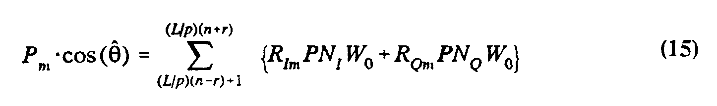
- the signals produced by the pilot extraction accumulators 882 and 886 correspond to I-channel and Q-channel projections of the pilot (P m ) signal transmitted over the m th path, and may be respectively represented as: Referring to FIG. 14, the I-channel and Q-channel projections of the pilot signal are each provided to both the I-channel phase rotator 850 and the Q-channel phase rotator 852.
- the I-channel phase rotator 850 produces a sequence of output data values corresponding to an estimate of the sequence r(t) transmitted over the m th path weighted by the pilot signal P m .
- the decision term generated by the I-channel phase rotator 850 at the conclusion of the n th correlation interval may be represented as:
- Equation (18) may be solved by performing, for example, a Fast Hadamard Transform (FHT) upon the upon the sequences provided the multiplexer 870 (FIG. 12).
- FHT Fast Hadamard Transform
- the symbol stream estimates are then deinterleaved and decoded in order to estimate the transmitted data.
Abstract
Description


Claims
Priority Applications (11)
| Application Number | Priority Date | Filing Date | Title |
|---|---|---|---|
| RU96112185A RU2142201C1 (en) | 1993-11-01 | 1994-11-01 | Alternating rate station transmission in spread spectrum communication system using group encoding |
| KR1019960702256A KR100221669B1 (en) | 1993-11-01 | 1994-11-01 | Method and apparatus for variable rate signal transmission in a spread spectrum communication system using coset coding |
| EP95901735A EP0727116B1 (en) | 1993-11-01 | 1994-11-01 | Variable rate signal transmission in a spread spectrum communication system using coset coding |
| AT95901735T ATE287158T1 (en) | 1993-11-01 | 1994-11-01 | VARIABLE DATA RATE SIGNAL TRANSMISSION IN A SPREAD SPECTRUM COMMUNICATIONS SYSTEM USING COSET (COSET) CODING |
| JP7513361A JP2925742B2 (en) | 1993-11-01 | 1994-11-01 | Variable rate signal transmission in spread spectrum communication systems using COSET coding |
| DE69434231T DE69434231T2 (en) | 1993-11-01 | 1994-11-01 | SIGNAL TRANSMISSION AT A TEMPORARY DATA RATE IN A SPREADING SPECTRUM COMMUNICATION SYSTEM USING BY-SIDE CLASSES (COSET) CODING |
| AU10862/95A AU678653B2 (en) | 1993-11-01 | 1994-11-01 | Variable rate signal transmission in a spread spectrum communication system using coset coding |
| CA002174344A CA2174344C (en) | 1993-11-01 | 1994-11-01 | Variable rate signal transmission in a spread spectrum communication system using coset coding |
| BR9407920A BR9407920A (en) | 1993-11-01 | 1994-11-01 | Transmitter for modulating an information signal for transmission in a spread spectrum communication system transmitter and method for modulating a set of P equivalent data rate information signals for simultaneous transmission in a spread spectrum communication system the spread spectrum communication system to modulate an information signal to be transmitted in phase (I) and quadrature phase (Q) using a carrier signal and a replica of said s |
| FI961823A FI116433B (en) | 1993-11-01 | 1996-04-29 | Transmission of a variable speed signal in a spread-spectrum communication system using common coding |
| HK98110095A HK1011474A1 (en) | 1993-11-01 | 1998-08-21 | Variable rate signal transmission in a spread spectrum communication system using coset coding. |
Applications Claiming Priority (2)
| Application Number | Priority Date | Filing Date | Title |
|---|---|---|---|
| US146,642 | 1993-11-01 | ||
| US08/146,642 US5471497A (en) | 1993-11-01 | 1993-11-01 | Method and apparatus for variable rate signal transmission in a spread spectrum communication system using coset coding |
Publications (1)
| Publication Number | Publication Date |
|---|---|
| WO1995012938A1 true WO1995012938A1 (en) | 1995-05-11 |
Family
ID=22518307
Family Applications (1)
| Application Number | Title | Priority Date | Filing Date |
|---|---|---|---|
| PCT/US1994/012540 WO1995012938A1 (en) | 1993-11-01 | 1994-11-01 | Variable rate signal transmission in a spread spectrum communication system using coset coding |
Country Status (17)
| Country | Link |
|---|---|
| US (1) | US5471497A (en) |
| EP (1) | EP0727116B1 (en) |
| JP (1) | JP2925742B2 (en) |
| KR (1) | KR100221669B1 (en) |
| CN (2) | CN1064800C (en) |
| AT (1) | ATE287158T1 (en) |
| AU (1) | AU678653B2 (en) |
| BR (1) | BR9407920A (en) |
| CA (1) | CA2174344C (en) |
| DE (1) | DE69434231T2 (en) |
| FI (1) | FI116433B (en) |
| HK (2) | HK1011474A1 (en) |
| IL (1) | IL111449A (en) |
| RU (1) | RU2142201C1 (en) |
| TW (1) | TW313726B (en) |
| WO (1) | WO1995012938A1 (en) |
| ZA (1) | ZA948560B (en) |
Cited By (16)
| Publication number | Priority date | Publication date | Assignee | Title |
|---|---|---|---|---|
| US5548253A (en) * | 1995-04-17 | 1996-08-20 | Omnipoint Corporation | Spectrally efficient quadrature amplitude modulator |
| US5742583A (en) * | 1994-11-03 | 1998-04-21 | Omnipoint Corporation | Antenna diversity techniques |
| US5832022A (en) * | 1995-06-02 | 1998-11-03 | Omnipoint Corporation | Method and apparatus for controlling the modulation index of continuous phase modulated (CPM) signals |
| FR2782587A1 (en) * | 1998-08-20 | 2000-02-25 | France Telecom | CDMA communication method, e.g. for mobile radio telephone system, distributing channel-characterizing reference signals in only I or Q components of signal |
| US6041046A (en) * | 1995-07-14 | 2000-03-21 | Omnipoint Corporation | Cyclic time hopping in time division multiple access communication system |
| EP0840960B1 (en) * | 1995-07-26 | 2003-01-15 | Ericsson Inc. | Method and apparatus for cdma signal orthogonalization |
| EP2114040A1 (en) * | 1997-11-03 | 2009-11-04 | Qualcom Incorporated | Method and apparatus for high rate packet data transmission |
| US7751371B2 (en) | 1995-02-28 | 2010-07-06 | Qualcomm Incorporated | Method and apparatus for providing variable rate data in a communications system using non-orthogonal overflow channels |
| US7848285B2 (en) | 1997-11-03 | 2010-12-07 | Qualcomm Incorporated | Method and apparatus for high rate packet data transmission |
| US8064409B1 (en) | 1999-08-25 | 2011-11-22 | Qualcomm Incorporated | Method and apparatus using a multi-carrier forward link in a wireless communication system |
| EP2259634A3 (en) * | 1995-06-30 | 2013-08-07 | Interdigital Technology Corporation | Code acquisition in a CDMA communication system |
| US9107109B2 (en) | 2000-10-25 | 2015-08-11 | Qualcomm Incorporated | Method and apparatus for determining a data rate in a high rate packet data wireless communications system |
| US9118387B2 (en) | 1997-11-03 | 2015-08-25 | Qualcomm Incorporated | Pilot reference transmission for a wireless communication system |
| US9426821B2 (en) | 2000-10-25 | 2016-08-23 | Qualcomm Incorporated | Method and apparatus for high rate packet data and low delay data transmissions |
| RU2691745C1 (en) * | 2018-11-02 | 2019-06-18 | Акционерное общество "Научно-исследовательский институт Приборостроения имени В.В. Тихомирова" | Data transmission method |
| RU2729042C1 (en) * | 2019-07-17 | 2020-08-04 | Федеральное Государственное Казенное Военное Образовательное Учреждение Высшего Образования "Военный Учебно-Научный Центр Сухопутных Войск "Общевойсковая Академия Вооруженных Сил Российской Федерации" | Method and apparatus for processing ft signal with discrete phase adjustment in economical mode |
Families Citing this family (85)
| Publication number | Priority date | Publication date | Assignee | Title |
|---|---|---|---|---|
| US6693951B1 (en) | 1990-06-25 | 2004-02-17 | Qualcomm Incorporated | System and method for generating signal waveforms in a CDMA cellular telephone system |
| USRE39954E1 (en) | 1993-07-16 | 2007-12-25 | Matsushita Electric Industrial Co., Ltd. | Automobile on-board and/or portable telephone system |
| JP2863975B2 (en) * | 1993-07-16 | 1999-03-03 | 松下電器産業株式会社 | CDMA transmitting apparatus and receiving apparatus, CDMA transmitting method and CDMA mobile communication system |
| CN1065091C (en) * | 1993-09-03 | 2001-04-25 | Ntt移动通信网株式会社 | Code division multiplex transmitter/receiver |
| IL111469A0 (en) | 1993-11-01 | 1994-12-29 | Omnipoint Corp | Despreading/demodulating direct sequence spread spectrum signals |
| KR960003102B1 (en) * | 1993-12-01 | 1996-03-04 | 재단법인 한국전자통신연구소 | Channel modulation circuit of cdma modulation apparatus |
| KR100326312B1 (en) * | 1994-06-17 | 2002-06-22 | 윤종용 | Synchronous transceiver of spread spectrum communication manner |
| US5621752A (en) * | 1994-06-23 | 1997-04-15 | Qualcomm Incorporated | Adaptive sectorization in a spread spectrum communication system |
| US5856998A (en) | 1994-09-09 | 1999-01-05 | Omnipoint Corporation | Method and apparatus for correlating a continuous phase modulated spread spectrum signal |
| US5757847A (en) | 1994-09-09 | 1998-05-26 | Omnipoint Corporation | Method and apparatus for decoding a phase encoded signal |
| US5610940A (en) | 1994-09-09 | 1997-03-11 | Omnipoint Corporation | Method and apparatus for noncoherent reception and correlation of a continous phase modulated signal |
| US5881100A (en) | 1994-09-09 | 1999-03-09 | Omnipoint Corporation | Method and apparatus for coherent correlation of a spread spectrum signal |
| US5963586A (en) | 1994-09-09 | 1999-10-05 | Omnipoint Corporation | Method and apparatus for parallel noncoherent correlation of a spread spectrum signal |
| US5680414A (en) | 1994-09-09 | 1997-10-21 | Omnipoint Corporation | Synchronization apparatus and method for spread spectrum receiver |
| US5832028A (en) | 1994-09-09 | 1998-11-03 | Omnipoint Corporation | Method and apparatus for coherent serial correlation of a spread spectrum signal |
| US5627856A (en) | 1994-09-09 | 1997-05-06 | Omnipoint Corporation | Method and apparatus for receiving and despreading a continuous phase-modulated spread spectrum signal using self-synchronizing correlators |
| US5754584A (en) | 1994-09-09 | 1998-05-19 | Omnipoint Corporation | Non-coherent spread-spectrum continuous-phase modulation communication system |
| US5754585A (en) | 1994-09-09 | 1998-05-19 | Omnipoint Corporation | Method and apparatus for serial noncoherent correlation of a spread spectrum signal |
| US5953370A (en) | 1994-09-09 | 1999-09-14 | Omnipoint Corporation | Apparatus for receiving and correlating a spread spectrum signal |
| US5648982A (en) | 1994-09-09 | 1997-07-15 | Omnipoint Corporation | Spread spectrum transmitter |
| US5692007A (en) | 1994-09-09 | 1997-11-25 | Omnipoint Corporation | Method and apparatus for differential phase encoding and decoding in spread-spectrum communication systems with continuous-phase modulation |
| US5629956A (en) | 1994-09-09 | 1997-05-13 | Omnipoint Corporation | Method and apparatus for reception and noncoherent serial correlation of a continuous phase modulated signal |
| US5659574A (en) | 1994-09-09 | 1997-08-19 | Omnipoint Corporation | Multi-bit correlation of continuous phase modulated signals |
| US5659573A (en) * | 1994-10-04 | 1997-08-19 | Motorola, Inc. | Method and apparatus for coherent reception in a spread-spectrum receiver |
| US5784293A (en) * | 1994-11-03 | 1998-07-21 | Motorola, Inc. | Apparatus and method for determining transmitted modulation symbols |
| US5784403A (en) * | 1995-02-03 | 1998-07-21 | Omnipoint Corporation | Spread spectrum correlation using saw device |
| ZA961025B (en) * | 1995-02-28 | 1996-07-16 | Qualcomm Inc | Method and apparatus for providing variable rate data in a communications system using non-orthogonal overflow channels |
| JP2705623B2 (en) * | 1995-03-22 | 1998-01-28 | 日本電気株式会社 | Diversity transmission / reception method and transceiver |
| US7929498B2 (en) * | 1995-06-30 | 2011-04-19 | Interdigital Technology Corporation | Adaptive forward power control and adaptive reverse power control for spread-spectrum communications |
| US7020111B2 (en) | 1996-06-27 | 2006-03-28 | Interdigital Technology Corporation | System for using rapid acquisition spreading codes for spread-spectrum communications |
| US5764688A (en) * | 1995-06-30 | 1998-06-09 | Roke Manor Research Limited | Apparatus for use in equipment providing a digital radio link between a fixed and a mobile radio unit |
| US6885652B1 (en) | 1995-06-30 | 2005-04-26 | Interdigital Technology Corporation | Code division multiple access (CDMA) communication system |
| US5748677A (en) * | 1996-01-16 | 1998-05-05 | Kumar; Derek D. | Reference signal communication method and system |
| US5781583A (en) * | 1996-01-19 | 1998-07-14 | Motorola, Inc. | Method and system for communication over multiple channels in a spread spectrum communication system |
| JP2820919B2 (en) | 1996-03-25 | 1998-11-05 | 株式会社ワイ・アール・ピー移動通信基盤技術研究所 | CDMA mobile communication system and transceiver |
| US6678311B2 (en) * | 1996-05-28 | 2004-01-13 | Qualcomm Incorporated | High data CDMA wireless communication system using variable sized channel codes |
| US5982813A (en) * | 1996-09-30 | 1999-11-09 | Amsc Subsidiary Corporation | Demand-based power and data rate adjustments to a transmitter to optimize channel capacity and power usage with respect to data transmission traffic over a fixed-bandwidth channel |
| US6496543B1 (en) | 1996-10-29 | 2002-12-17 | Qualcomm Incorporated | Method and apparatus for providing high speed data communications in a cellular environment |
| US5923651A (en) * | 1996-12-23 | 1999-07-13 | Alcatel Usa Sourcing, L.P. | Increasing data throughput in a wireless telecommunications environment |
| US5771229A (en) * | 1997-01-31 | 1998-06-23 | Motorola, Inc. | Method, system and mobile communication unit for communicating over multiple channels in a wireless communication system |
| US7751370B2 (en) | 2001-07-13 | 2010-07-06 | Qualcomm Incorporated | Method and apparatus for forward link rate scheduling |
| US6335922B1 (en) | 1997-02-11 | 2002-01-01 | Qualcomm Incorporated | Method and apparatus for forward link rate scheduling |
| DE19708626C2 (en) * | 1997-03-04 | 1999-08-05 | Rohde & Schwarz | Radio communication system working according to the spread spectrum method |
| US5982807A (en) | 1997-03-17 | 1999-11-09 | Harris Corporation | High data rate spread spectrum transceiver and associated methods |
| US6301288B1 (en) | 1997-03-19 | 2001-10-09 | Infineon Technologies Ag | Method of chip interleaving in direct sequence spread spectrum communications |
| US6061386A (en) * | 1997-03-19 | 2000-05-09 | I.C. Com Ltd. | Method of chip interleaving in direct sequence spread spectrum communications |
| US6226259B1 (en) * | 1997-04-29 | 2001-05-01 | Canon Kabushiki Kaisha | Device and method for transmitting information device and method for processing information |
| US6215762B1 (en) | 1997-07-22 | 2001-04-10 | Ericsson Inc. | Communication system and method with orthogonal block encoding |
| WO1999009666A1 (en) * | 1997-08-15 | 1999-02-25 | Motorola Inc. | Method for processing data in a communication system receiver |
| US6285655B1 (en) * | 1997-09-08 | 2001-09-04 | Qualcomm Inc. | Method and apparatus for providing orthogonal spot beams, sectors, and picocells |
| US6052598A (en) * | 1997-09-30 | 2000-04-18 | At&T Corp | Method for predicting the location of a mobile station in a mobile communications network |
| EP0909020B1 (en) * | 1997-10-10 | 2006-01-11 | Alcatel | Hybrid fiber-coax telecommunication system |
| US6810030B1 (en) * | 1997-10-17 | 2004-10-26 | Lucent Technology | Dynamic and smart spreading for wideband CDMA |
| US6026117A (en) * | 1997-10-23 | 2000-02-15 | Interdigital Technology Corporation | Method and apparatus for generating complex four-phase sequences for a CDMA communication system |
| US6067646A (en) * | 1998-04-17 | 2000-05-23 | Ameritech Corporation | Method and system for adaptive interleaving |
| WO2000019732A2 (en) * | 1998-09-29 | 2000-04-06 | Samsung Electronics Co., Ltd. | Device and method for generating spreading code and spreading channel signals using spreading code in cdma communication system |
| GB9823605D0 (en) | 1998-10-29 | 1998-12-23 | Koninkl Philips Electronics Nv | Radio communication system |
| US6128330A (en) | 1998-11-24 | 2000-10-03 | Linex Technology, Inc. | Efficient shadow reduction antenna system for spread spectrum |
| US6847658B1 (en) | 1998-12-10 | 2005-01-25 | Qualcomm, Incorporated | Demultiplexer for channel interleaving |
| US6721349B1 (en) * | 1999-01-28 | 2004-04-13 | Qualcomm Incorporated | Method and apparatus for reducing peak-to-average ratio in a CDMA communication system |
| US6658045B1 (en) * | 1999-02-22 | 2003-12-02 | Nortel Networks Limited | CDMA communications system adaptive to mobile unit speed |
| US7443906B1 (en) | 1999-05-31 | 2008-10-28 | Electronics And Telecommunications Research Institute | Apparatus and method for modulating data message by employing orthogonal variable spreading factor (OVSF) codes in mobile communication system |
| US6643332B1 (en) * | 1999-07-09 | 2003-11-04 | Lsi Logic Corporation | Method and apparatus for multi-level coding of digital signals |
| KR20010087669A (en) * | 2000-03-08 | 2001-09-21 | 서평원 | Apparatus for transmitter of base station in communication system |
| WO2001080438A1 (en) * | 2000-04-18 | 2001-10-25 | Linkair Communications. Inc. | A method of orthogonal conversion of spread spectrum multiple access code |
| US6539209B1 (en) * | 2000-05-30 | 2003-03-25 | Lucent Technologies Inc. | Code-division, multiple-access base station having transmit diversity |
| AU2000252051A1 (en) * | 2000-06-09 | 2001-12-17 | Linkair Communications. Inc. | A method of channel estimation and the system employing the method |
| US6859643B1 (en) * | 2000-08-04 | 2005-02-22 | Lucent Technologies Inc. | Power amplifier sharing in a wireless communication system with amplifier pre-distortion |
| US6731668B2 (en) * | 2001-01-05 | 2004-05-04 | Qualcomm Incorporated | Method and system for increased bandwidth efficiency in multiple input—multiple output channels |
| FR2825551B1 (en) * | 2001-05-30 | 2003-09-19 | Wavecom Sa | METHOD FOR ESTIMATING THE TRANSFER FUNCTION OF A TRANSMISSION CHANNEL OF A MULTI-CARRIER SIGNAL, METHOD OF RECEIVING A DIGITAL SIGNAL, AND RECEIVER OF A MULTI-CARRIER SIGNAL THEREOF |
| BR0205740A (en) * | 2001-07-12 | 2004-02-03 | Samsung Electronics Co Ltd | Reverse Transmission Apparatus and Method for Improving Transmission Quality in a Data Communication System |
| US6795489B2 (en) * | 2001-08-09 | 2004-09-21 | Qualcomm Inc. | Acquisition of a gated pilot |
| US8086271B2 (en) * | 2001-09-12 | 2011-12-27 | Ericsson Inc. | Network architecture for mobile communication network with billing module for shared resources |
| US7340017B1 (en) * | 2002-07-30 | 2008-03-04 | National Semiconductor Corporation | System and method for finger management in a rake receiver |
| CN102299886B (en) | 2004-12-23 | 2017-09-12 | 韩国电子通信研究院 | Device and method for generating and sending frame in a wireless communication system |
| US7917798B2 (en) | 2005-10-04 | 2011-03-29 | Hypres, Inc. | Superconducting digital phase rotator |
| US8920343B2 (en) | 2006-03-23 | 2014-12-30 | Michael Edward Sabatino | Apparatus for acquiring and processing of physiological auditory signals |
| US7873125B2 (en) * | 2006-11-30 | 2011-01-18 | Broadcom Corporation | Method and system for sliding window phase estimator for WCDMA automatic frequency correction |
| US8331417B2 (en) | 2010-04-20 | 2012-12-11 | Los Alamos National Security, Llc | Energy efficiency in wireless communication systems |
| CN103929645B (en) * | 2013-12-13 | 2015-06-10 | 中国矿业大学(北京) | Distributed selection compression coding and decoding method based on coset codes |
| US9584243B2 (en) * | 2014-01-29 | 2017-02-28 | Qualcomm Incorporated | Orthogonal modulation using M-sequences and Hadamard transforms |
| RU2649418C2 (en) * | 2016-05-23 | 2018-04-03 | Алексей Романович Попов | Method of information transmission by noise-like signals in mobile tactical communication system |
| RU2646315C1 (en) * | 2016-11-14 | 2018-03-02 | Акционерное общество "Российская корпорация ракетно-космического приборостроения и информационных систем" (АО "Российские космические системы") | Method for forming a signal of a satellite navigation system |
| RU2660126C1 (en) * | 2017-09-22 | 2018-07-05 | Акционерное общество "Российская корпорация ракетно-космического приборостроения и информационных систем" (АО "Российские космические системы") | Method for forming glonass group navigation signal |
| US11445405B1 (en) * | 2021-06-17 | 2022-09-13 | Sprint Spectrum L.P. | Method and system for concurrently transmitting signals |
Citations (2)
| Publication number | Priority date | Publication date | Assignee | Title |
|---|---|---|---|---|
| WO1992000639A1 (en) * | 1990-06-25 | 1992-01-09 | Qualcomm Incorporated | System and method for generating signal waveforms in a cdma cellular telephone system |
| FR2681199A1 (en) * | 1991-09-11 | 1993-03-12 | Europ Agence Spatiale | Method and device for multiplexing data signals |
Family Cites Families (7)
| Publication number | Priority date | Publication date | Assignee | Title |
|---|---|---|---|---|
| US4507648A (en) * | 1982-02-08 | 1985-03-26 | At&T Bell Laboratories | Decoding technique for multidimensional codes |
| US5040191A (en) * | 1987-02-24 | 1991-08-13 | Codex Corporation | Partial response channel signaling systems |
| US4896353A (en) * | 1988-09-23 | 1990-01-23 | Unisys Corp. | Apparatus for fast decoding of a non-linear code |
| US5150381A (en) * | 1989-02-16 | 1992-09-22 | Codex Corporation | Trellis shaping for modulation systems |
| US5317639A (en) * | 1989-10-04 | 1994-05-31 | Teledyne Industries, Inc. | Non-linear block substitution devices derived by constructive corruption |
| US5297170A (en) * | 1990-08-21 | 1994-03-22 | Codex Corporation | Lattice and trellis-coded quantization |
| US5353352A (en) * | 1992-04-10 | 1994-10-04 | Ericsson Ge Mobile Communications Inc. | Multiple access coding for radio communications |
-
1993
- 1993-11-01 US US08/146,642 patent/US5471497A/en not_active Expired - Lifetime
-
1994
- 1994-10-30 IL IL11144994A patent/IL111449A/en not_active IP Right Cessation
- 1994-10-31 ZA ZA948560A patent/ZA948560B/en unknown
- 1994-11-01 EP EP95901735A patent/EP0727116B1/en not_active Expired - Lifetime
- 1994-11-01 AU AU10862/95A patent/AU678653B2/en not_active Ceased
- 1994-11-01 DE DE69434231T patent/DE69434231T2/en not_active Expired - Lifetime
- 1994-11-01 CN CN94193946A patent/CN1064800C/en not_active Expired - Fee Related
- 1994-11-01 AT AT95901735T patent/ATE287158T1/en not_active IP Right Cessation
- 1994-11-01 BR BR9407920A patent/BR9407920A/en not_active Application Discontinuation
- 1994-11-01 WO PCT/US1994/012540 patent/WO1995012938A1/en active IP Right Grant
- 1994-11-01 CA CA002174344A patent/CA2174344C/en not_active Expired - Fee Related
- 1994-11-01 RU RU96112185A patent/RU2142201C1/en not_active IP Right Cessation
- 1994-11-01 JP JP7513361A patent/JP2925742B2/en not_active Expired - Lifetime
- 1994-11-01 KR KR1019960702256A patent/KR100221669B1/en not_active IP Right Cessation
- 1994-12-14 TW TW083111687A patent/TW313726B/zh active
-
1996
- 1996-04-29 FI FI961823A patent/FI116433B/en not_active IP Right Cessation
-
1998
- 1998-08-21 HK HK98110095A patent/HK1011474A1/en not_active IP Right Cessation
-
2000
- 2000-09-11 CN CNB001289640A patent/CN1148906C/en not_active Expired - Fee Related
-
2001
- 2001-11-16 HK HK01108120A patent/HK1037286A1/en not_active IP Right Cessation
Patent Citations (2)
| Publication number | Priority date | Publication date | Assignee | Title |
|---|---|---|---|---|
| WO1992000639A1 (en) * | 1990-06-25 | 1992-01-09 | Qualcomm Incorporated | System and method for generating signal waveforms in a cdma cellular telephone system |
| FR2681199A1 (en) * | 1991-09-11 | 1993-03-12 | Europ Agence Spatiale | Method and device for multiplexing data signals |
Non-Patent Citations (1)
| Title |
|---|
| FORNEY: "Coset codes-Part I: Introduction and geometrical classification", IEEE TRANSACTIONS ON INFORMATION THEORY, vol. IT34, no. 5, September 1988 (1988-09-01), NEW YORK US, pages 1123 - 1151 * |
Cited By (30)
| Publication number | Priority date | Publication date | Assignee | Title |
|---|---|---|---|---|
| US5742583A (en) * | 1994-11-03 | 1998-04-21 | Omnipoint Corporation | Antenna diversity techniques |
| US7751371B2 (en) | 1995-02-28 | 2010-07-06 | Qualcomm Incorporated | Method and apparatus for providing variable rate data in a communications system using non-orthogonal overflow channels |
| US5548253A (en) * | 1995-04-17 | 1996-08-20 | Omnipoint Corporation | Spectrally efficient quadrature amplitude modulator |
| US5832022A (en) * | 1995-06-02 | 1998-11-03 | Omnipoint Corporation | Method and apparatus for controlling the modulation index of continuous phase modulated (CPM) signals |
| US9564963B2 (en) | 1995-06-30 | 2017-02-07 | Interdigital Technology Corporation | Automatic power control system for a code division multiple access (CDMA) communications system |
| EP2259634A3 (en) * | 1995-06-30 | 2013-08-07 | Interdigital Technology Corporation | Code acquisition in a CDMA communication system |
| US6041046A (en) * | 1995-07-14 | 2000-03-21 | Omnipoint Corporation | Cyclic time hopping in time division multiple access communication system |
| EP0840960B1 (en) * | 1995-07-26 | 2003-01-15 | Ericsson Inc. | Method and apparatus for cdma signal orthogonalization |
| US8005042B2 (en) | 1997-11-03 | 2011-08-23 | Qualcomm Incorporated | Method and apparatus for high rate packet data transmission |
| US9118387B2 (en) | 1997-11-03 | 2015-08-25 | Qualcomm Incorporated | Pilot reference transmission for a wireless communication system |
| US7848285B2 (en) | 1997-11-03 | 2010-12-07 | Qualcomm Incorporated | Method and apparatus for high rate packet data transmission |
| US7848283B2 (en) | 1997-11-03 | 2010-12-07 | Qualcomm Incorporated | Method and apparatus for high rate packet data transmission |
| US7848284B2 (en) | 1997-11-03 | 2010-12-07 | Qualcomm Incorporated | Method and apparatus for high rate packet data transmission |
| US7995531B2 (en) | 1997-11-03 | 2011-08-09 | Qualcomm Incorporated | Method and apparatus for high rate packet data transmission |
| US9124344B2 (en) | 1997-11-03 | 2015-09-01 | Qualcomm Incorporated | Pilot reference transmission for a wireless communication system |
| US8009625B2 (en) | 1997-11-03 | 2011-08-30 | Qualcomm Incorporated | Method and apparatus for high rate packet data transmission |
| EP2114040A1 (en) * | 1997-11-03 | 2009-11-04 | Qualcom Incorporated | Method and apparatus for high rate packet data transmission |
| US8077655B2 (en) | 1997-11-03 | 2011-12-13 | Qualcomm Incorporated | Method and apparatus for high rate packet data transmission |
| US8089924B2 (en) | 1997-11-03 | 2012-01-03 | Qualcomm Incorporated | Method and apparatus for high rate packet data transmission |
| US8189540B2 (en) | 1997-11-03 | 2012-05-29 | Qualcomm Incorporated | Method and apparatus for high rate packet data transmission |
| US8311027B2 (en) | 1997-11-03 | 2012-11-13 | Qualcomm Incorporated | Method and apparatus for high rate packet data transmission |
| US8351372B2 (en) | 1997-11-03 | 2013-01-08 | Qualcomm Incorporated | Method and apparatus for high rate packet data transmission |
| WO2000011814A1 (en) * | 1998-08-20 | 2000-03-02 | France Telecom | Digital communication methods with distributed reference symbols |
| US6424644B1 (en) | 1998-08-20 | 2002-07-23 | France Telecom | CDMA digital communication processes with distribution of reference symbols |
| FR2782587A1 (en) * | 1998-08-20 | 2000-02-25 | France Telecom | CDMA communication method, e.g. for mobile radio telephone system, distributing channel-characterizing reference signals in only I or Q components of signal |
| US8064409B1 (en) | 1999-08-25 | 2011-11-22 | Qualcomm Incorporated | Method and apparatus using a multi-carrier forward link in a wireless communication system |
| US9107109B2 (en) | 2000-10-25 | 2015-08-11 | Qualcomm Incorporated | Method and apparatus for determining a data rate in a high rate packet data wireless communications system |
| US9426821B2 (en) | 2000-10-25 | 2016-08-23 | Qualcomm Incorporated | Method and apparatus for high rate packet data and low delay data transmissions |
| RU2691745C1 (en) * | 2018-11-02 | 2019-06-18 | Акционерное общество "Научно-исследовательский институт Приборостроения имени В.В. Тихомирова" | Data transmission method |
| RU2729042C1 (en) * | 2019-07-17 | 2020-08-04 | Федеральное Государственное Казенное Военное Образовательное Учреждение Высшего Образования "Военный Учебно-Научный Центр Сухопутных Войск "Общевойсковая Академия Вооруженных Сил Российской Федерации" | Method and apparatus for processing ft signal with discrete phase adjustment in economical mode |
Also Published As
| Publication number | Publication date |
|---|---|
| RU2142201C1 (en) | 1999-11-27 |
| KR960706241A (en) | 1996-11-08 |
| AU678653B2 (en) | 1997-06-05 |
| CN1133659A (en) | 1996-10-16 |
| US5471497A (en) | 1995-11-28 |
| HK1011474A1 (en) | 1999-07-09 |
| KR100221669B1 (en) | 1999-09-15 |
| CN1295391A (en) | 2001-05-16 |
| AU1086295A (en) | 1995-05-23 |
| DE69434231D1 (en) | 2005-02-17 |
| ATE287158T1 (en) | 2005-01-15 |
| FI961823A0 (en) | 1996-04-29 |
| DE69434231T2 (en) | 2005-12-08 |
| BR9407920A (en) | 1996-11-26 |
| CA2174344A1 (en) | 1995-05-11 |
| IL111449A0 (en) | 1994-12-29 |
| CN1064800C (en) | 2001-04-18 |
| IL111449A (en) | 1999-09-22 |
| FI961823A (en) | 1996-06-28 |
| EP0727116B1 (en) | 2005-01-12 |
| TW313726B (en) | 1997-08-21 |
| CA2174344C (en) | 2007-07-31 |
| EP0727116A1 (en) | 1996-08-21 |
| JP2925742B2 (en) | 1999-07-28 |
| ZA948560B (en) | 1995-06-30 |
| FI116433B (en) | 2005-11-15 |
| JPH09504923A (en) | 1997-05-13 |
| CN1148906C (en) | 2004-05-05 |
| HK1037286A1 (en) | 2002-02-01 |
Similar Documents
| Publication | Publication Date | Title |
|---|---|---|
| US5471497A (en) | Method and apparatus for variable rate signal transmission in a spread spectrum communication system using coset coding | |
| US5414728A (en) | Method and apparatus for bifurcating signal transmission over in-phase and quadrature phase spread spectrum communication channels | |
| US5805567A (en) | Orthogonal modulation scheme | |
| CA2212265C (en) | Is-95 compatible wideband communication scheme | |
| EP0829155B1 (en) | Doubly orthogonal code and frequency division multiple access communication system | |
| RU2313176C2 (en) | Client block and method for using it in a wireless communication system | |
| EP0564937A1 (en) | CDMA Radio communication system with pilot signal transmission between base and handsets for channel distortion compensation | |
| JPH08509590A (en) | Method and apparatus for time division multiplexing the use of spreading codes in a communication system | |
| US6018547A (en) | Method and apparatus for increasing spectral efficiency of CDMA systems using direct sequence spread spectrum signals | |
| JPH07107007A (en) | Spreading code generation system | |
| US7433385B1 (en) | Code division multiple access communication | |
| JP3534796B2 (en) | Spread spectrum communication method, transmitter and receiver thereof | |
| KR100230719B1 (en) | Device for building transmit-channel of cdma system | |
| MXPA94008488A (en) | Method and apparatus for bifurcating signal transmission over in-phase and quadrature phase spread spectrum communication channels | |
| PNI | llllllllllllllllllllllllllllllg? lullllllllllllllllllllllllllllllllll |
Legal Events
| Date | Code | Title | Description |
|---|---|---|---|
| WWE | Wipo information: entry into national phase |
Ref document number: 94193946.4 Country of ref document: CN |
|
| AK | Designated states |
Kind code of ref document: A1 Designated state(s): AM AT AU BB BG BR BY CA CH CN CZ DE DK EE ES FI GB GE HU JP KE KG KP KR KZ LK LR LT LU LV MD MG MN MW NL NO NZ PL PT RO RU SD SE SI SK TJ TT UA UZ VN |
|
| AL | Designated countries for regional patents |
Kind code of ref document: A1 Designated state(s): KE MW SD SZ AT BE CH DE DK ES FR GB GR IE IT LU MC NL PT SE BF BJ CF CG CI CM GA GN ML MR NE SN TD TG |
|
| DFPE | Request for preliminary examination filed prior to expiration of 19th month from priority date (pct application filed before 20040101) | ||
| 121 | Ep: the epo has been informed by wipo that ep was designated in this application | ||
| WWE | Wipo information: entry into national phase |
Ref document number: 2174344 Country of ref document: CA |
|
| WWE | Wipo information: entry into national phase |
Ref document number: 1995901735 Country of ref document: EP Ref document number: 961823 Country of ref document: FI |
|
| WWE | Wipo information: entry into national phase |
Ref document number: 1019960702256 Country of ref document: KR |
|
| WWP | Wipo information: published in national office |
Ref document number: 1995901735 Country of ref document: EP |
|
| REG | Reference to national code |
Ref country code: DE Ref legal event code: 8642 |
|
| WWG | Wipo information: grant in national office |
Ref document number: 1995901735 Country of ref document: EP |
|
| WWG | Wipo information: grant in national office |
Ref document number: 961823 Country of ref document: FI |