WO1996041361A2 - Method and apparatus for producing and using plasma - Google Patents
Method and apparatus for producing and using plasma Download PDFInfo
- Publication number
- WO1996041361A2 WO1996041361A2 PCT/US1996/003859 US9603859W WO9641361A2 WO 1996041361 A2 WO1996041361 A2 WO 1996041361A2 US 9603859 W US9603859 W US 9603859W WO 9641361 A2 WO9641361 A2 WO 9641361A2
- Authority
- WO
- WIPO (PCT)
- Prior art keywords
- lattice
- stable plasma
- particles
- plasma inside
- solid material
- Prior art date
Links
Classifications
-
- G—PHYSICS
- G21—NUCLEAR PHYSICS; NUCLEAR ENGINEERING
- G21B—FUSION REACTORS
- G21B3/00—Low temperature nuclear fusion reactors, e.g. alleged cold fusion reactors
-
- Y—GENERAL TAGGING OF NEW TECHNOLOGICAL DEVELOPMENTS; GENERAL TAGGING OF CROSS-SECTIONAL TECHNOLOGIES SPANNING OVER SEVERAL SECTIONS OF THE IPC; TECHNICAL SUBJECTS COVERED BY FORMER USPC CROSS-REFERENCE ART COLLECTIONS [XRACs] AND DIGESTS
- Y02—TECHNOLOGIES OR APPLICATIONS FOR MITIGATION OR ADAPTATION AGAINST CLIMATE CHANGE
- Y02E—REDUCTION OF GREENHOUSE GAS [GHG] EMISSIONS, RELATED TO ENERGY GENERATION, TRANSMISSION OR DISTRIBUTION
- Y02E30/00—Energy generation of nuclear origin
- Y02E30/10—Nuclear fusion reactors
Definitions
- This invention is a breakthrough in the field of very high density plasmas and plasma solid fusion.
- This invention presents a method and apparatus that allow the creation of stable condensed matter inside a solid, a very high density stable plasma, and some of its many uses, including plasma solid fusion.
- This plasma can be used to store a large quantity of chemical energy or to produce nuclear fusion.
- Hydrogen also represents another potential source of energy: Deuterium, which constitutes 0.015 % of the total hydrogen on the planet, is a potential fuel for nuclear fusion which is an ideal source of energy: in more than thirty years, a great deal of work has been conducted in the field of high temperature controlled plasma fusion to achieve this end. However, despite massive investment in expensive and complicated apparatus such as the Toka ak, the successful production of energy by high temperature plasma fusion does not appear to be any closer. In addition to the production of energy, these methods produce some particles (neutrons, gamma, he1 ium, ... ) . SUMMARY OF THE PRESENT INVENTION.
- the present invention is for a method and apparatus that allows the creation of a high density plasma of protons, deuterons or tritons. These three particles will be noted symbolically H D T + to simplify later notation.
- This plasma has a very high density (10 to 10 particles/cm ) .
- H D T are released from the solid under atomic (H) and molecular (H j ) form, they can be used as a source of chemical energy to fuel engines and turbines. If the protons or deuterons are released as charged particles (H + , D + ) , they can be accelerated and used to propel a rocket in space. Inside the metal, the plasma has a particular and unique structure which gives it stability, and allows certain H D T to approach each other without electric repulsion, and then to fusion. The heat produced by these thermonuclear reactions can be used among others for domestic heating or to desalinize sea water (this could be a source of cheap, potable water, especially for dry countries which borders oceans), or to produce cheap electricity, etc... Nuclear Physics applications are also possible.
- Fig.l shows an electrolytic bath required for the loading of plasma solid.
- Fig.2 represents the electrochemical mechanism of hydrogen inside the cathode.
- Fig.3 represents a diagram of the potential in function of Log i .
- Fig.4 illustrates the relationship between Log i fl and the volume apparent V, for different metals.
- Fig. 5a shows the potential in function of Log i ft for the palladium in acid solution.
- Fig. 6a shows an elementary energy cell inside the Palladium.
- Fig. 6b is an elementary cell inside the Palladium.
- Fig. 7a, 7b, and 7c represents different kind of pulsed currents .
- Fig. 8 represents a top view of an interface metal-plasma gas.
- Fig 9. represents a top view of an interface metal- hydrogen gas.
- Fig. 10a represents a top view of an interface ionic solution-metal-plasma gas.
- Fig. 10b represents a top view of another mixed interface ionic solution-metal-plasma gas.
- Fig. 11 represents a top view of a mixed interface usable in a vehicle.
- Fig. 12a represents a top view of a mixed interface usable to propel a rocket.
- Fig. 12b is a cross section of a rocket propelled using plasma solid.
- Fig. 13a depicts an elementary plasma cell with its plasma crown or nanotokamak.
- Fig. 13b depicts the orbital surrounding the plasma crown inside an elementary plasma cell.
- Fig. 14 depicts a cross section of an apparatus designed to discharge an energy wave inside a cathode loaded with plasma solid.
- the plasma can be created inside metallic materials from an ionic solution or a plasma gas.
- the H D T submitted to an electrical field, penetrate inside the solid.
- the method is electrochemical.
- A) Position of the Hydrogen Mechanism Figure 1 describes an electrolytic bath with a cathode (10) made up of palladium (or of other specific alloys), the negative pole (11) of a direct current source, an anode (12) made up of platinum and the positive pole (13) of the said source.
- the electrolyte (14) is an ionic solution with an acid or basic pH. Instead of using water (H 2 0) for diluting the chemical product, heavy water such as D,0 or T,0 can be used. It has been well known for years that any metal, alloy or other electrical conductor, may function as the cathode of an electrolytic apparatus. It is also well known that such a cathode will attract positively charged particles, in the bath, such as H D T + and positively charged ions.
- the first step of the hydrogen mechanism is produced inside electrode 20 in layer 21, 3000 A to 5000 A thick, including the surface atoms ( Figure 2).
- the size of the H D T + is 10-1" A°. Compared to the size of other ions ( 1 A° to o several A), and the interatomic distance at the surface of the metal (about 2 A), the size of the H D T + is relatively small. This explains why H D T + , if endowed with enough energy, can easily penetrate the metallic electrode.
- the H D T are in perpetual movement, passing from a water molecule to another easily. As soon as a cathodic potential is applied to the electrode, the H D T proceed to the surface of the metal.
- the time interval t needed to conclude those two electrochemical steps is short, but much longer than the time interval needed by the other H D T + to penetrate inside the metal. Because of the electric field generated, the free H D T + must react with electrons. However, since the metallic atoms of the surface are already occupied by hydrogen atoms, the free H D T + can not extract electrons from those surface atoms.
- the thickness of layer 21 depends of the potential applied at the electrode, if the potential is not too cathodic. For very cathodic potentials, the thickness o of the layer reaches a limit comprised between 3000 A and 5000 A, for which the nature of the metal has no great influence. This limit expresses the fact that the penetration of protons is impeded by the presence of numerous electrons in the metal. The nature of the metal exerts a very large influence on the second electrochemical step 25. For some metals, the second step occurs only at the surface of the electrode.
- the second step occurs under the surface of the electrode in layer 3000 A to 5000 A thick. This layer is the same as the one where the first step occurs.
- the layers 26 for other metals are comprised between the results for the two o previous categories of metal (0 to 5000 A).
- the electrochemical mechanism produces an energy of 31.3 eV.
- the energy is used to place the metallic atoms of the layer in a state of vibration, disperse the H D T inside the layer and help them find the reactional sites available for reaction, disperse atomic hydrogen in the layer and inside the metal, and push the molecular hydrogen outside the electrode after the reaction.
- the molecular hydrogen can not penetrate the core of the electrode because it is static: this part of the electrode thus acts as a fence which prevents the diffusion of molecular hydrogen inward.
- V ⁇ cum is the volume apparent of the atom
- V j is the real volume of the atom calculated as a sphere of radius R atomic.
- the value of Log i is obtained by reading the intersection of this second part of the curve with the axis of Log i.
- the second electrochemical step occurs in a layer whose thickness is directly related to the nature of the metal. This value of Log in is therefore a good descriptive parameter of the second electrochemical step and is therefore related to the depth of the layer.
- Figure 4 presents the evolution of Log i n in function of the apparent atomic volume in acid solution for all the metals studied in the literature: Ag, Al , As, Au, Bi, Co, Cu, Cd, Cr, Fe, Ga, Ge, Hg, In, Ir, Mo, Mn, Nb, Ni , Pb, Pd, Pt , Re, Rh, Ru, Sb, Si, Sm, Ta, Tc, Te, Ti , Tl , V, W, Zn, Zr.
- the curve shows a general tendency: when the atomic volumes increase, the value of Log i n increases and passes by a maximum. Its value for great atomic volumes is very low.
- the maximum of the curve is obtained for ruthenium, iridium, osmium, technetium, palladium and platinum (V a consult comprised between 13.8 A and 15.2 A ).
- the curve presents numerous anomalies for metals such as copper, vanadium, manganese, and zinc. These results, apparently abnormal, are very interesting because they show that other factors intervene and allow to understand the hydrogen mechanism more completely. Two other parameters are important: the hardness of the metal and its affinity toward hydrogen.
- the hardness and Log i ⁇ are inversely proportional.
- Figure 4 presents the first resonance phenomenon during the hydrogen o 1 mechanism:
- the free available atomic volume Vr (the free volume of the elementary cell) is too small within the metal.
- the reaction is possible only near the surface of the electrode where the metallic atoms can move more easily.
- the vibrations of the metal provoked by the energy generated by the first elementary step allows the creation of the elementary cells necessary for the second steps.
- the free atomic volume V j of the elementary cell is large enough for the formation of an hydrogen molecule.
- the two atoms H of hydrogen are created and trapped in an elementary cell whose size is only slightly greater than the size of an hydrogen molecule.
- the distance between the two atoms H is o close to 1.2 A, the distance of Van der Waals below which two atoms of hydrogen are forced to form a molecule of hydrogen.
- the energy produced by the two steps (31.3 eV) forces the two hydrogen atoms to become a hydrogen molecule.
- the free volume ol inside the elementary cell has a size of about 4 A and acts as a resonant cavity for the hydrogen molecules.
- V the metals of atomic volumes
- the free volume of the elementary ce l l is much larger than the volume of the hydrogen molecule.
- two hydrogen atoms have enough space not to interact.
- the second step becomes more difficult to realize since the large elementary cell cannot force the two hydrogen atoms to form an hydrogen molecule.
- V increases, the value of
- the metals without any affinity toward hydrogen can be divided ol into two groups : ( V a ⁇ 15 A , Co, Cu, Cr, Ni, Fe, Os, Ir, Ru, Rh,...) and ( V,d ⁇ 15 A 3 , Pt , Au, Ag, Mo, W, Al , ... ) .
- 16 A allows the reproduction of the first resonance phenomenon by creating a free volume inside the cell of about ol
- Some of these alloys are: Cu Ag, Co Au,, Ni Ag j , Fe Al,, Ni A1 j , Ni Au,, Ni A ⁇ , • .. ) , but many other combinations are possible.
- curves 5a and 5b present the' potential V of the palladium in function of Log i.
- the palladium electrode behaves as if it were a superconductor.
- the electrons can move inside the metal with a speed measured in .s , while protons can only achieve speeds measured in mm.s .
- the palladium stores the plasma, whose concentration increases with time.
- the structure of palladium explains the formation of plasma.
- the palladium cathode is made of PdH ⁇ ,, .
- Two thirds of the palladium atoms are bound with one hydrogen atom. The remaining third are completely free to react. Therefore, there are two categories of elementary cells (presented in Figure 6). To simplify the drawing, the cell is represented as if the Palladium were cubic in shape.
- the first category 60 is that of the elementary energy cells. There is no hydrogen atom bound to a metallic atom inside this kind of elementary cell.
- the volume of the cell is completely available for the electrochemical mechanism: 2 H + + 2 e " -> H 2 + 31.3 eV An energy of 31.3 eV is produced with each hydrogen molecule.
- the energy only appears in this kind of elementary cell, hence the name elementary energy cell.
- the energy created inside the electrode is transmitted to the protons that are dispersed in all directions inside the electrode, the hydrogen molecules in the form of kinetic energy which helps them depart the electrode and the palladium atoms, which receive the energy by impulse.
- the second category 61 is that of the elementary plasma cell. These cells have one hydrogen atom bound inside. They represent two thirds of all existing elementary cells. In these cells, the volume available is approximately equal to the volume of an hydrogen atom.
- the elementary plasma cell has a free available volume of about oi
- the effect of the impulses and of the vibrations is cumulative. Some forced oscillations appear if the frequency of the oscillations is close to one of the frequency of the electrode; the amplitude of the vibrations then increases. The compressions and extensions of the elementary cells increases to large degrees, and the metal fatigue produced by these large amplitude variations creates cracks in the metal. For lower pH, a dislocation force caused by the pressure created by the large plasma concentration also exists. When there are many cracks on the surface, the vibrations can only propagate in some small parts of this surface. The cumulative effect of the vibrations and the plasma inside disappear. Understanding this second resonance phenomenon allows to create alloys that duplicate this property.
- the alloys must possess a resonant cavity or free available volume inside the elementary cell comprised o ⁇ oi between 1.75 A and 2.5 A .
- the cavity has the size and shape to accommodate only one hydrogen atom. But because of the vibrations of the metal and the excess H D T + in the cavity, the H D T + and electrons inside the free volume remain under the form of plasma. It is possible to build this particular cavity inside alloys by several means:
- the first mean is to duplicate the structure of Palladium.
- the alloys must present the first resonance phenomenon property and produce the hydrogen molecule already described (available free volume in O 1 01 the elementary cell comprised between 3.75 A and 4.5 A ).
- One of the metal composing the alloy must present an affinity toward hydrogen.
- the alloys must be a combination of:
- Ol free available volume vary between 5 and 6 A or 5.62 and
- Ol A third method to create a resonant cavity of 2 A is to bond three hydrogen atoms in an available free volume of about four hydrogen atoms (8 A 3 )
- the average apparent atomiic volume V, o such an alloy or metal should be 3 d f around 30 A
- a fourth method to duplicate the properties of Palladium is to use very small atoms without hydrogen bonded inside the elementary cell.
- Beryllium and Boron have an affinity toward hydrogen.
- the hydrogen atoms created in the layer under the surface can migrate in all directions. Progressively, it is possible to saturate the inside of the palladium electrode from PdHg ⁇ to PdH with basic or acid solutions. Once the saturation is obtained (one hydrogen atom per palladium atom), the entire core of the electrode is converted into plasma cells. The free volume available per palladium atom is equal to the volume of one hydrogen atom. The electrode thus becomes a layer of energy and plasma cell surrounding a core composed uniquely of plasma cells.
- the "plasma cells" of the cathode are of two kind.
- the "plasma cells” of the layer are in a state of vibration and can store plasma. Those "plasma cells” are active. The core of the electrode is static. The “plasma cells” in this region can not store plasma. These “plasma cells” are passive. As seen previously in Figure 4, for a given atomic volume V, the Log i» parameter diminishes when the hardness of the metal increases. This means that the movement of the metallic atoms is very important for the electrochemical mechanism. The larger the movement of the atoms are, the thicker the active layer will be. Every time two protons meet two electrons in an energy cell, an energy of 31.3 eV is produced. The creation of this elementary energy, as well as the vibrations it produces, is chaotic.
- the synchronization of energy formation inside the layer allows us to increase the amplitude of the vibrations of the metallic atoms.
- the amplitude of the vibrations can be adjusted in function of the application desired.
- the use of the resonance phenomenon creates areas where the vibrations are at their maximum. These areas, where the stationary waves are at their maximum, occupy a large part of the total volume of the electrode.
- the protons submitted to the metallic vibrations are dispersed throughout the electrode, including the core composed of plasma cells. Because of the resonance phenomenon, certain regions of the core are zones where the vibrations are at their maximum: the plasma cells become active and can thereafter store the H D T under their plasma form. It is therefore possible to obtain plasma-solid both in the active layer and in 50 % or more of the electrode (active regions of the core).
- the volume of the electrode that can be used is increased by a factor of about 1000.
- the free volume (4 A ) inside the cell represents approximately 25 to 29 % of the total volume of the lattice ol
- the plasma cells is contained in the free volume (2 A ).
- the free volume inside the cell o has the approximate shape of a sphere (radius 0.8 A).
- the plasma is not homogeneous.
- H D T As other H D T enter, they occupy a kind of spherical crown or ring located between two spheres of o o respective radii 0.75 A and 0.8 A.
- the volume of the crown o 1 is about 0.3 A .
- the thickness of this plasma crown increases when the concentration of plasma increases.
- the plasma is in constant movement inside the spherical crown.
- the H D T move in one direction.
- the electrons move in the other direction to avoid the attraction between the two particles.
- the movements of the two opposite electrical charges in opposite directions are equivalent to the movements of two parallel electrical currents of similar electrical charge in the same direction.
- a "Pinch effect" thus appears between these moving charges which allows the plasma to be stabilized inside the spherical crown. If the electrons were moving in the same direction as the H D T + , the magnetic field generated would be repulsive and the plasma would be unstable. Only the plasma crowns with H D T + and electrons moving in opposite directions are stable. The size of the spherical crown is not constant because the plasma is constantly submitted to the vibrations generated by the metallic atoms. If the vibrations imposed on the plasma are regular and symmetrical, the central symmetry of the plasma crown is preserved. Because the movement of the opposite electrical charges is equivalent to two electrical current moving in the same direction, the plasma crown behaves as a spherical toroid.
- the magnetic field B generated by the moving charges is equal to 0 outside the plasma crown. Because of the central symmetry, the H D T and the electrons have the same center of electrical charge at the center of the spherical crown. Because the two centers of the electrical charges occupy the same position, the plasma does not emit any electrical field inside and outside the plasma crown.
- the structure of the plasma in this particular situation is similar to that found in a tokamak.
- the "elementary cells" behave as small tokamak or "nanotoka aks .
- the shape of the cell is not cubic, the shape of the plasma crown can be ellipsoidal. Likewise, if the vibrations are not applied symmetrically, the shape of the plasma crown can be asymmetrical. However, in these cases, as in the case of the spherical plasma crown, the electric field is nil inside and outside the plasma crown because of the electrical neutrality of the plasma and Gauss' law . The magnetic field is also nil outside the plasma crown. F) Conditions Required to Retain and Release the Plasma Solid
- H D T + which form the plasma solid can enter under many different forms, such as atoms, molecules, or H D T , from many different media such as ionic solutions with H D T , plasma gas of H D T , or atmospheres of hydrogen atoms or molecules. If the particles are charged, moving the particles inside the solid will entail using electrical means. If the particles are electrically neutral atoms or molecules, moving the particles inside the solid will entail manipulating the pressure of the gas.
- F-l) Interface Metal-Ionic Solution If the particles are charged, moving the particles inside the solid will entail using electrical means. If the particles are electrically neutral atoms or molecules, moving the particles inside the solid will entail manipulating the pressure of the gas.
- the method is a classical electrolysis.
- the ionic solutions can have any pH value — basic or acid.
- the time needed in a basic solution to produce the plasma inside the electrode is longer because the plasma only begins to appear when each elementary cell holds a hydrogen atom.
- the solution has to be in constant motion -- through magnetic agitation or with a pump -- in order to maintain similar properties at the surface of the cathode. To avoid contamination of the cathode, the solutions have to be very pure.
- the metal will lose its surface characteristics.
- the anode has to be made of a noble or unimpeachable metal (platinum for example).
- the surface of the anode must be large enough to avoid limiting the current- density passing through the cathode.
- the metal of the cathode must be made of Palladium, or of an alloy which respect the specific conditions of the triple resonance phenomenon inside the elementary cell as previously set forth.
- the free volume ol inside the elementary cell must be smaller than 2.5 A .
- the layer several microns deep around the core may be composed of different components, or of the same material. But because of the electrochemical mechanism of hydrogen, as seen in the case of Palladium, the elementary cells inside this layer are divided between energy cells and plasma cells.
- the layer may be made of an alloy with a preset percentage of energy cells varying from 0 to 100% of the total number of cells in the layer.
- the " energy cells” inside the layer produce energy at the same frequency as the pulsed current, thus creating and maintaining stationary waves inside the cathode. Inserting more “ energy cells” inside the layer will prevent the destruction of the " elementary plasma cells” if the plasma concentration becomes too large.
- the creation of alloys will also allow the choice of atoms with more protons in their nucleus: the greater the number of protons in the nucleus, the greater the compression effect at the center of the cell will be.
- the mechanical properties of the alloys created will also be superior to those of the pure metals: they are harder, and will therefore be able to resist better to the plasma pressure. This will allow us to create plasma of higher densities inside the electrode.
- the movements of the metallic atoms are more constrained, but this flaw can be compensated by the application of vibration to the electrode.
- the cathode can be of any shape, but for some applications it will be of great import.
- the wire which transmits current to the electrode must be insulated from the solution.
- the intensity of the current-density can be large. since only a small percentage of the current-density can be used to charge the electrode with atomic hydrogen. It can take several hours to increase the concentration from PdH n concerned to PdH. For acid solutions of pH ⁇ 1, the creation of plasma is far easier.
- the current-density threshold necessary to begin plasma storage is comprised between 0.1 A.cm -2 and 0.2 A.cm-2. This threshold correspond to the energy necessary to initiate vibrations of sufficient amplitude to keep the H D T under the form of plasma. To charge the electrode rapidly, it is possible to
- the amplitude of the vibrations is controllable by adjusting the amplitude of the current-densi y pulse or the amplitude of the sound (or ultrasound) used to generate the vibrations.
- the degree of compression of the plasma is directly related to the amplitude of the vibrations applied.
- the fixation of the cathode must be realized with great precision at the vibration nodes to establish the stationary waves consistently.
- the temperature of the electrode can have two effects: a high temperature allows the metal of the electrode to soften, and therefore increase the level of vibrations of the electrode and a high temperature of the electrode is necessarily accompanied by a high temperature of the ionic solution, since the solution is a carrier of the heat generated by the electrode.
- the high temperature increases the ther odynamic efficiency of the turbine. Since the solutions are aqueous, it is necessary to work with high pressures to obtain high temperature and keep the solutions in a liquid state.
- the interface metal-plasma gas can be realized in an apparatus of the type described in Figure 8.
- the cathode (81) composed of palladium (or alloy already described), concentric in shape (or other) is positioned at the center of the enclosure (82).
- the plasma injectors (83) are distributed uniformly on the surface of the enclosure (82).
- the injectors are of the model found in the literature: they can be, for example, a molecular hydrogen stream subjected to electrical discharges (the discharges break the hydrogen molecule into H D T + and electrons).
- a power source (84) applies a potential difference between the cathode and the anode.
- a non-conductor is placed in position (85) to avoid any contact between the wire leading to the cathode and the enclosure.
- Another power source (87) is connected to the cathode so as to adjust its temperature.
- the voltage applied between the anode and the cathode is adjustable and can be very high. It is much higher than the voltage used in the metal-ionic solution (about 2 V). Due to these large potentials, the H D T arrive on the cathode with very high kinetic energies.
- the voltage is pulsed at the resonance frequency of the electrode, so as to create stationary waves inside the cathode.
- manipulating the power source (87) it is possible to control the temperature of the cathode.
- An increase in temperature allows the metal to soften and facilitate an increase in the amplitude of the vibrations of the metallic atoms.
- the maximal particle concentration is
- isotope three is the most interesting for thermonuclear fusion reaction.
- Figure 9 (top view) present another method to create H D T plasma crowns inside a cathode 91 made of one of the specific alloy already described.
- the cathode is placed inside a metallic enclosure 90 containing an hydrogen atmosphere 93 .
- the hydrogen pressure is maintained constant thanks to hole 96.
- Cathode 91 (a cube on Figure 9) is held through the center of its faces by the fixtures 92 which are electrical conductors. Insulator 94 prevents any electrical contact between enclosure 90 and the fixtures 92.
- a source of electrical power 95 maintains a potential between the cathode 91 and the enclosure 90.
- Generators 97 produce acoustic or ultrasonic energy which can be adjusted to one of the resonance frequency of the cathode 91.
- the vibrations can also be transmitted to the solid material using a magnetic transducer.
- Hole 98 allows the departure of the hydrogen stored under the form of plasma inside cathode 91.
- the hydrogen molecules come into contact with cathode 91, they divide into hydrogen atoms and penetrate inside the cathode under the effect of hydrogen pressure.
- the hydrogen atoms diffuse inside the metal and bond with one of the metallic atom of each cell, the elementary cells become plasma cells.
- the other hydrogen atoms submitted to the vibrations of the metal, turn into plasma and progressively fill the plasma crowns.
- the release of the hydrogen can be accelerated by polarizing positively cathode 91 in comparison to enclosure 90 using electrical power source 95.
- This apparatus can also be used to create He 2+ plasma crowns in the metal or alloy with the proper resonant cavities from an helium atmosphere.
- the mechanism works by first loading the plasma, then, in a second period, releasing it.
- the interest of a double interface, or mixed interface is to separate the two functions so as to be able to use them both at the same time.
- Plasma loading can be conducted using an ionic solution in one compartment. It could occur continuously.
- the release of the plasma through the second compartment is conducted under the control of a power source.
- the second compartment can be filled with ionic solution, plasma gas, hydrogen gas or vacuum.
- Figure 10a describes a mixed interface ( etal-plasma gas )-(metal-ionic solution).
- the cathode is placed at the interface between the two compartments.
- the first compartment holds an ionic solution, the second a plasma gas.
- the cathode (100) is made of a metal or alloy already described. One side of the cathode is in contact with the ionic solution (101). The cathode can then be loaded with plasma through the surface in contact with the ionic solution. The other side of the cathode belongs to the second compartment.
- the ionic solution is in constant movement. It enters and departs through the tubes 111 so as to maintain a constant pH at the surface of the cathode.
- the flow of the ionic solution also allows for the removal of the hydrogen molecules created by the cathode.
- the anode (102) made of a noble metal or of an alloy which cannot pollute the cathode, is separated from the cathode (100) by a porous membrane (104) to avoid the mixing of oxygen and hydrogen.
- a power source (103) maintains a current-density flow composed of two elements, a continuous current density and a pulsed current density, which allows the plasma loading of the cathode from H D T + in the ionic solution.
- Part 105 is a non-conductor through which the wire that establishes the electric contact between the cathode and the two power sources passes.
- the non-conductor (105) constitutes the separation between the two compartments. Part (105) also allows to maintain the two extremities of the cathode in a fixed position and determine with exactitude the characteristics of the stationary waves. Other fixtures at the nodes of vibration can be installed.
- the second compartment is the same as the one described in the previous paragraph: enclosure as anode (106), plasma injector (107) cavity for vacuum pump (108), a power source (109).
- the function of the second compartment is variable with time and depends of the chosen application.
- the power source (109) which produces pulsed current-density at the same frequency as in the first compartment, and the plasma flow created by the injectors are maintained at the lowest possible levels to avoid the departure of the plasma solid from the cathode.
- the potential delivered by power source (109) is adjusted to a sufficient value to prevent the plasma from leaving the cathode.
- the potential of the power source (109) allows to control the exit of the plasma through exit 110.
- the injectors (107) are stopped.
- Another interesting use for this double interface could be the use of another configura ion ( Figure 10b): the ionic solution passes through the cathode while the different compartment retain their own function. The flow of ionic solution allows to control the temperature of the cathode and transfer the heat generated inside the cathode.
- the second compartment can be filled with vacuum or hydrogen gas.
- This method can be generalized to elements other than hydrogen: Helium, Lithium, Beryllium, Boron, ...
- the Helium particles small enough to enter the solid material are the He atom, the He ion and the He + ion in a plasma gas.
- the solid material in which a stable plasma of He 2+ particles can be created has two kinds of resonant cavities.
- the first kind which have the approximate size of an He atom, allow to transform the He atoms in He ions.
- the other kind, which has the approximate size of an He ion allow to transform Hef ions into He2t ions and create a plasma ii , 2+ f crown of He * .
- These cavities can contain a mix of He , H D T and electrons inside the plasma crown.
- usable particles are Li ions from ionic solutions, plasma gases or molten salts.
- the solid material must be composed of two kind of cavities: cavities of the size of an Li ion, in
- usable particles are Be" ions from ionic solutions, plasma gases or molten salts.
- the solid material must be composed of two kind of cavities: cavities of the size of an Be" ion, in which Be 3+ ions are formed thanks to the resonance phenomenon, and cavities of the size of the Be where the plasma crown of Be4+ ions is created.
- These plasma crowns can also contain a mix of Be Li 3+ and H D T + ions.
- usable particles are B ions in plasma gases.
- the solid material must be composed of two kind of cavities: cavities of the size of an B ion, in which B ions are formed thanks to th hee resonance phenomenon, and cavities of the size of the B , + where the plasma crown of B ions is created.
- These plasma crowns can also contain a mix of B , Be , He , Li and H D T ions. These different plasma crowns can be used for plasma solid fusion.
- the plasma constitutes a storage of matter, a storage of electrical charges, and a storage of energy.
- the H D T appear under the form of charged particles or of molecules, depending on the nature of the compartment in which the release occurs.
- UTILIZATION OF THE PLASMA SOLID The plasma solid contained in specially designed materials and submitted to controlled vibrations can be used in different ways, depending of the amplitude of the vibrations applied to the cathode. If the amplitude of the vibration only reaches the limit needed to prevent the reaction of H D T and electrons, the cathode can be used to store energy or matter. For this application, the vibrations can be pulsed at a different frequency than the resonant frequency of the solid material.
- the rate of standing waves inside the solid is not 100%. This rate increases the volume of the solid material affected by vibrations, so that a maximum volume of the solid material can be used to create and store plasma. If the amplitude of the vibrations is larger, the H D T will interact together and provoke a thermonuclear fusion or a plasma solid fusion. If the amplitude is still greater, the interaction will extend beyond the interaction of plasma particles to the interaction of the H D T with nuclei of the metallic atoms. G) Storage of Energy, Electrical Charges, and Matter.
- the plasma composed of H D T + and electrons is located inside the "plasma cell," in a small part of the free volume (approximately 2 A °3).
- the shape of the area where the plasma can be found is a complex volume, and changes constantly because of the vibrations of the metallic atoms. However, it can be simplified to a spherical crown, or the area located between two spheres of radii 0.75 and 0.8 A . The probability is highest to find the plasma in the outer area of the spherical crown, on the sphere of radii 0.8 A, in a volume of about 0.3 A .
- the plasma is always non- static.
- the size of the spherical crown is not constant because the plasma is constantly submitted to the vibrations of the metallic atoms.
- the center of the negative electrical charges plasma is located at or near the center of the spherical crown. The same goes for the positive electrical charges generated by the H D T . Since the two centers of opposite electrical charges occupy the same position, the ol plasma does not emit any electric field outside the 0.3 A of the plasma crown (because of the symmetrical distribution of the electrical charges). If the vibrations imposed on the plasma are regular and symmetrical, the two centers of electric charges occupy a same position. In this case, both the metallic structure of the cathode and the plasma are stable. In these conditions, the plasma solid can be used for the storage of energy, electrical charges, or matter.
- the plasma crown can hold between one and fifteen H D T + or the equivalent of 10 23 to 1024 particles per cubic centimeter of cathode.
- This high density plasma solid constitutes a storage of energy under two forms.
- the H D T + and electrons are kept separated inside the plasma.
- the particles When the particles are allowed to associate after leaving the cathode, they produce molecular hydrogen and an energy of 31.3 eV per molecule of H, , or an
- gasoline produces about 5 10 ki lojoule/mole or 35 10 3 kilojoule/dm3 of gasoline, or in a tank of 60 cubic decimeter, about 2 10 kilojoule.
- Tubes (111) are used for the circulation of the ionic solution.
- the functions of the first compartments are the loading of plasma overnight and, thanks to power source (103), the continuous creation of a state of vibration that maintains the plasma within the cathode.
- the second compartment has two functions: - the first function of this compartment is to prevent the escape of plasma from cathode (100) when there is no need for molecular hydrogen. To accomplish this function, the second compartment is filled with an ionic solution.
- the polarities of electrodes (100) and (102) are the same as the one described for the first function.
- the difference in potential allows us to load more protons inside cathode (100) through the surface of the second compartment, and maintain or increase the concentration of plasma already inside.
- the second principal function of the second compartment is to allow the departure of plasma.
- the ionic solution is completely emptied from the second compartment through tubes (111) which are closed once the operation is completed. Only tube (110) remains open.
- Switch (112) disconnect the anode (102) and connects electrode (106) to the power source (109). This power source provides a negative potential to electrode (106) when compared to electrode (100).
- the H D T + can leave electrode (100), then react with electrons at the surface of electrode (106) to become molecular hydrogen. Some hydrogen molecules may leave electrode (106) with negative charges which are neutralized by H D T + coming from the opposite direction.
- the second compartment then fills with H 2 - The reaction energy appears simultaneously (2H + + e " -> H 2 + 31.3 eV) .
- the pressure of molecular hydrogen increases and a flow of hydrogen leaves the second compartment ' through tube (110). This hydrogen can then be burned in a turbine, which is more efficient than the internal combustion engine.
- An alternator coupled with the turbine produces the electricity required to supply the electric motors of cars or trains. In the case of an airplane, the flow of hydrogen can directly supply a turbojet.
- such a double compartment is interesting because it allow us to separate loading and deloading between the first and the second compartment, and control, thanks to the applied potential difference, the flow of molecular hydrogen.
- the use of plasma solid will have many beneficial consequences, especially for the environment. Remark: For these kind of vehicles( car, train, plane, etc... ) , the cathode filled with plasma solid can be reloaded overnight under a low voltage and a high intensity current. Another way to reload the cathodes would be to use standard cathodes. Once empty, the standard plasma solid cathodes can be exchanged at a plasma solid reloading station where standard plasma solid cathodes are loaded continuously.
- the standard plasma solid cathode can be reloaded almost instantaneously in special plasma solid reloading stations.
- the empty cathode is pressed forcefully against the surface of a considerably larger cathode filled with plasma solid.
- This larger cathode is loaded continuously. This process takes place inside an ionic solution.
- the vibrations used on the two cathodes have the same frequency, one of the resonance frequencies common to both cathodes. Once the two cathodes are pressed together under the same resonance frequency, they behave as one.
- the plasma solid contained inside the large cathode moves easily inside the empty cathode.
- the plasma solid concentration inside the large cathode does not vary significantly.
- the standard cathode is thus loaded rapidly at the same concentration. After reloading, the standard cathode is transferred to the vehicle, while still inside the ionic solution and under the potential provided by the vehicle so as to avoid the escape of plasma from the cathode during the transfer.
- the quantity of plasma solid transferred can be measured simply by weighing the mass of the cathode before and after the loading.
- the storage of plasma solid can be a source of energy for jet propulsion.
- One of the better propel lant used to propel rockets is a mix of liquid hydrogen and oxygen.
- the first compartment is the same as the one described in Figure 10 a. It has the same parts as the one described in the previous paragraphs.
- the first compartment allows the continuous loading of plasma, and the retention of the plasma inside the electrode through the induction of a state of vibration.
- the second compartment has two essential functions: - the first function is to keep the plasma inside cathode (100) when there is no use for the plasma. To accomplish this function, electrodes (120) has a positive potential when compared to cathode (100). An ionic solution is used to fill the second compartment so as to control the flow of all particles, and prevent, thanks to the polarity of power source 121, the exit of the plasma.
- the second function is to propel the rocket by allowing the protons to leave cathode (100).
- the ionic solution filling the second compartment is removed with a pump through cavity (122) at the rear of the rocket.
- Door (123) is opened to establish a contact between the cathode and the vacuum outside the rocket.
- a high voltage is applied between cathode (100) and exhaust nozzle (124) (positive potential to cathode (100) and negative potential to exhaust nozzle (124) ).
- the polarity difference compel the protons to depart cathode (100). Thanks to the high voltage, the protons are then expelled at very high speeds, thus propelling the rocket.
- the flow of proton can be control led both by adjusting the vol tage and by adjusting the surface of cathode (100) in the second compartment .
- door (123) can be closed and the ionic solution can be reintroduced in the second compartment.
- the loading polarity is then reestablished.
- a separate beam of electrons (125) is ejected to enable the recombination to take place behind the vehicle and prevent the rocket from becoming electrically charged.
- Such propulsion is interesting because it provides high specific impulse and therefore low propellant consumption. It is reusable, highly efficient, light weight and present very low maintenance cost.
- the plasma solid can be created using deuterons.
- the plasma solid also represents a high density storage of electrical charges.
- One cubic decimeter of plasma solid at the concentration of 1 contains an electrical charge of 10 coulombs in electrons. It is equivalent to ten times the charge contained in a capacitor of one farad charged under a potential of 10 D Volt.
- the opposite charges of the plasma solid can be separated easily by changing the potential of the cathode.
- This plasma can thus be the source of a very high intensity current in an isolated vehicle such as a car, train, plane, etc...
- Figure 11 presents a possible use of this application in a vehicle.
- the flow of electrons which passes through power source 109 is equivalent to a high intensity current.
- the large volume of hydrogen formed on electrode 106 can be burned to feed the turbogenerator which furnishes the electrical energy used by power source 109. Thanks to this energy , it is possible to maintain a current of large amplitude which can be used to create a magnetic field of large intensity. This field can be used to move or stop a vehicle, or for magnetic levitation, which eliminates the friction of the vehicle with the ground.
- G-4) Tritium Storage The plasma solid can be used to store tritium which in gaseous form occupies a large volume.
- H) Plasma Solid Fusion One of the mechanisms of plasma solid fusion occurs at the level of the plasma crown.
- Figure 13a and 13b present, in the diagonal section of the cube, the plasma crown or nanotokamak as it exists inside the elementary plasma cell. Each vertex is occupied by a metallic atom M. Between the eight atoms of the cubes, inside the free available volume, an hydrogen atom is bound to the metallic structure. The plasma crown 131 occupies the remnant of this volume.
- Figure 13b shows the plasma surrounded by the deformed orbitals of the four metallic atoms and of the bound hydrogen atom. For this application, all the parameters already discussed to create plasma solid remain valid. But the fusion reactions inside the cathode depend on the composition of the plasma solid.
- the ionic solution must contain H , D , or T , or a mixture of two or three of these isotopes.
- the choice of the reaction will ultimately determine the composition of the solution. Since the penetration of the isotopes inside the electrode will be determined by the respective weight of the isotopes, the composition of the plasma inside the electrode will be different from the composition of the solution. The lighter the isotope, the more easily it will penetrate the electrode. If the experiment entails the loading of a mixture of isotopes, the process can be divided into two steps: the heavier isotopes are used first, followed in a second time by the protons whose lesser weight make them easier to load.
- a H D T moving through a transfer channel will be able to approach the plasma crown without being subjected to any force from the plasma crown. Because of the properties of the crown, the incoming H D T can get very close to any H D T + of the crown without impediment. When the two H D T + enter the field of nuclear force of the other, they attract one another and fusion. If the H D T + does not meet another H D T + in the first plasma crown, it crosses it without perturbation, and goes on to the next and so on, until it meets another H D T + and fusion. The same phenomenon occurs for the electrons.
- thermonuclear reactions can be realized:
- the heat produced by plasma solid fusion can be used directly for domestic purposes such as heating, or for more arcane use such as sea water desal inization. By using a turbogenerator, the heat can also be used to produce electricity. As seen previously in F-2), F-3) and F-5), some alloys can allow the creation of plasma crowns of He , B , Be , Li , H D T + or plasma crowns containing any mix of the preceding. With these plasma crowns, some fusion reaction can also be produced:
- the reaction of plasma solid fusion produces byproducts, including particles alpha, gamma, and neutrons.
- the plasma solid fusion can also be a source of tritium.
- Two deuterons react inside the cathode by plasma solid fusion D (d,p) T and produce one triton. Inside the layer the triton can react electrochemical ly with a proton, a deuteron or another triton to form molecular hydrogen (HT, DT, or TT) which then departs the electrode.
- the tritium can thus be recuperated, by collecting the hydrogen , gases , for other utilization, or reinjected in the solution.
- the tritium produced during this first reaction react with a deuteron to produce: 2 H + 3 H -> 4 He + n + 17.6 MeV
- the neutrons can be produced in other plasma solid reactions. These neutrons then react with Li ions inside the ionic solution to produce:
- the neutrons can also react with the metallic nuclei to produce isotopes of the atoms of the cathode.
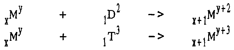
- 1-2) Transmutation If the amplitude of the pulse is vastly increased, the plasma particles will not only interact among each other but also with the nuclei of the metallic atoms of the cathode. If two H D T come through opposite sides of a transfer channel, there is a large probability that they will collide at the bottleneck. After the collision, the direction of the two H D T will have been altered considerably. Likewise, inside the plasma crown, the magnetic field is not nil. When a H D T crosses a plasma crown, its direction can be affected by the magnetic field inside the crown.
- H D T + then collides with enough speed with one of the metallic nucleus, it can fusion with the metal atom and provoke a transmutation. If there is no stripping during the fusion reaction, the interaction between the three different isotopes and a metallic atom M can have three different outcomes: + I H1 -> . 1
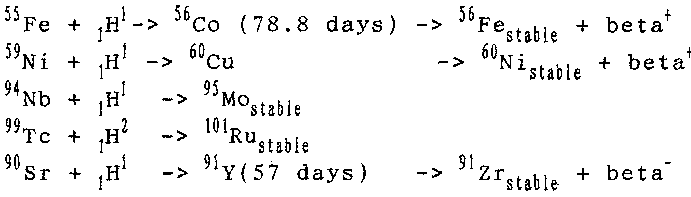
- this transmutation method can be applied to numerous elements. Among other applications, it can be used to convert radioactive elements into stable elements. It is easy to create alloys respecting the resonance conditions with the following radioactive fl 'i'i 59 . 94 91 U elements: ' ⁇ Sr, "Fe, "Ni , “N , “Tc, H C. If large vibrations are transmitted to the cathode, the following transmutations become possible:
- This method of transmutation can also be used to create scarce elements which have a specific value.
- the structure of the alloy only suffers minor modification after the transmutation since the elements created are of the same size as the elements they replaced.
- This method is interesting because the concentration of the plasma solid is high (10 23 to 10 24 H D T + . cm "3 ) .
- the method can be used to produce energy.
- the creation of the rare element or the transmutation of radioactive elements will occur as a byproduct of the reaction inside the cathode.
- the alloy of the cathode will thus be created to fulfill these two objectives.
- cathode 10 will preferably be of spherical or cylindrical shape. The size of the cathode will depend of the desired effect. The concentric shape of the cathode allows a very large compression of the plasma at the center of the cathode.
- Anode 12 is a platinum screen, one square decimeter or more in area, designed to avoid the creation of an upper limit to the amount of current that can pass through the anode.
- Solution 14 can be a mixture of protons and deuterons (DCl + HCl or D,SO,+ H 2 S0 4 ), or a pure solution of deuterons. These solutions are very acid and have a concentration of 10 21 H D T+ .cm-3.
- Power source 144 allows the creation of plasma solid. The discharge lasts about one second. To avoid the problem of diffusion at the cathode, the solution should be agitated [140] in the bath at a high speed.
- the serial and parallel combination of the capacitors 141 allows to obtain a capacity of approximately one Farad. These capacitors can then be charged under a 1000 volts voltage 142.
- the capacitors can accumulate an electric charge of a thousand Coulombs or the equivalent of 6 10 21 electrons and an energy of 5 10" Joules.
- the capacitors When the capacitors are connected by 143, they discharge in the bath. The energy is divided entirely between the ions of the solution.
- the 6 10 21 protons which enter the cathode bring with them an energy of 250 Joules.
- the plasma is only composed of deuteron, it is possible to create a large impulse of neutrons.
- the effect can be improved and augmented by the concentric shape of the cathode.
- the energy entering the cathode penetrates a layer
- This energy density is very large and melts parts of the metal which make up the cathode.
- the method can be used to realize a thermal process of the surface of the cathode.
- This large energy wave method can be used with other ions in the ionic solution or in gaseous plasma. Numerous ions have a radius smaller than
- these ions are solvated by several molecules of water.
- these ions lose the molecules of water, and are precipitated violently on the cathode.
- the layer of plasma inside the cathode acts as a wall.
- These ions collide with the H D T of the plasma at very high speeds, and produce different kind of nuclear reactions.
- the ions Li can react :
- the plasma solid can be used as a target inside an accelerator.
- the plasma inside the cathode represent a wall for the ions accelerated toward this target. Many nuclear reactions are possible. It can also serve as a target for a laser to provoke fusion reactions inside the cathode.
Abstract
Description
Claims
Priority Applications (4)
| Application Number | Priority Date | Filing Date | Title |
|---|---|---|---|
| EA199800847A EA199800847A1 (en) | 1996-03-22 | 1996-03-22 | METHOD OF PRODUCTION AND USE OF PLASMA (OPTIONS) AND DEVICE FOR ITS IMPLEMENTATION (OPTIONS) |
| BR9612728-7A BR9612728A (en) | 1996-03-22 | 1996-03-22 | Plasma production and use method and apparatus |
| EP96925244A EP0914668A2 (en) | 1995-06-06 | 1996-03-22 | Method and apparatus for producing and using plasma |
| AU65400/96A AU6540096A (en) | 1995-06-06 | 1996-03-22 | Method and apparatus for producing and using plasma |
Applications Claiming Priority (3)
| Application Number | Priority Date | Filing Date | Title |
|---|---|---|---|
| US46729895A | 1995-06-06 | 1995-06-06 | |
| US1292296P | 1996-03-06 | 1996-03-06 | |
| CA002249642A CA2249642A1 (en) | 1995-06-06 | 1996-03-22 | Method and apparatus for producing and using plasma |
Publications (2)
| Publication Number | Publication Date |
|---|---|
| WO1996041361A2 true WO1996041361A2 (en) | 1996-12-19 |
| WO1996041361A3 WO1996041361A3 (en) | 1997-02-06 |
Family
ID=27170837
Family Applications (1)
| Application Number | Title | Priority Date | Filing Date |
|---|---|---|---|
| PCT/US1996/003859 WO1996041361A2 (en) | 1995-06-06 | 1996-03-22 | Method and apparatus for producing and using plasma |
Country Status (4)
| Country | Link |
|---|---|
| EP (1) | EP0914668A2 (en) |
| AU (1) | AU6540096A (en) |
| CA (1) | CA2249642A1 (en) |
| WO (1) | WO1996041361A2 (en) |
Cited By (3)
| Publication number | Priority date | Publication date | Assignee | Title |
|---|---|---|---|---|
| WO2003098640A2 (en) * | 2002-05-17 | 2003-11-27 | The State Of Oregon Acting By And Through The State Board Of Higher Education On Behalf Of Portland State University | Processing radioactive materials with hydrogen isotope nuclei |
| WO2008048223A2 (en) * | 2005-08-05 | 2008-04-24 | Andre Jouanneau | Method and apparatus for the creation and utilization of hydrogen ordering materials (hydrom) |
| WO2023248107A1 (en) * | 2022-06-21 | 2023-12-28 | Aganyan Fusion | Method for controlled thermonuclear fusion |
Citations (6)
| Publication number | Priority date | Publication date | Assignee | Title |
|---|---|---|---|---|
| US3835019A (en) * | 1969-03-06 | 1974-09-10 | California Inst Of Techn | Combined electrolytic hydrogen gas separator and generator for gas chromatographic systems |
| US4274938A (en) * | 1978-02-18 | 1981-06-23 | Kernforschungsanlage Julich Gmbh | Apparatus for the production of hydrogen and oxygen |
| US4487670A (en) * | 1981-12-09 | 1984-12-11 | Commissariat A L'energie Atomique | Process for treating solutions containing tritiated water |
| EP0393465A2 (en) * | 1989-04-20 | 1990-10-24 | Semiconductor Energy Laboratory Co., Ltd. | Method for producing plasma nuclear fusion |
| EP0394980A2 (en) * | 1989-04-27 | 1990-10-31 | Matsushita Electric Industrial Co., Ltd. | Cold nuclear fusion apparatus |
| US4968395A (en) * | 1989-06-21 | 1990-11-06 | Richard Pavelle | Method and apparatus for increasing catalytic efficiency of electrodes |
Family Cites Families (5)
| Publication number | Priority date | Publication date | Assignee | Title |
|---|---|---|---|---|
| JPH02275397A (en) * | 1989-04-16 | 1990-11-09 | Hiroshi Kubota | Nuclear fusion apparatus |
| JPH0353195A (en) * | 1989-07-21 | 1991-03-07 | Matsushita Electric Ind Co Ltd | Energy generator |
| JPH03150494A (en) * | 1989-11-07 | 1991-06-26 | Toyoaki Omori | Nuclear fusion generator |
| JPH03226694A (en) * | 1990-02-01 | 1991-10-07 | Semiconductor Energy Lab Co Ltd | Method of electro-chemical low temperature nuclear fusion |
| JPH0634776A (en) * | 1992-07-15 | 1994-02-10 | Tokyo Electric Power Co Inc:The | Room temperature nuclear fusion heat generating device seam generating device and power plant |
-
1996
- 1996-03-22 AU AU65400/96A patent/AU6540096A/en not_active Abandoned
- 1996-03-22 CA CA002249642A patent/CA2249642A1/en not_active Abandoned
- 1996-03-22 EP EP96925244A patent/EP0914668A2/en not_active Ceased
- 1996-03-22 WO PCT/US1996/003859 patent/WO1996041361A2/en not_active Application Discontinuation
Patent Citations (6)
| Publication number | Priority date | Publication date | Assignee | Title |
|---|---|---|---|---|
| US3835019A (en) * | 1969-03-06 | 1974-09-10 | California Inst Of Techn | Combined electrolytic hydrogen gas separator and generator for gas chromatographic systems |
| US4274938A (en) * | 1978-02-18 | 1981-06-23 | Kernforschungsanlage Julich Gmbh | Apparatus for the production of hydrogen and oxygen |
| US4487670A (en) * | 1981-12-09 | 1984-12-11 | Commissariat A L'energie Atomique | Process for treating solutions containing tritiated water |
| EP0393465A2 (en) * | 1989-04-20 | 1990-10-24 | Semiconductor Energy Laboratory Co., Ltd. | Method for producing plasma nuclear fusion |
| EP0394980A2 (en) * | 1989-04-27 | 1990-10-31 | Matsushita Electric Industrial Co., Ltd. | Cold nuclear fusion apparatus |
| US4968395A (en) * | 1989-06-21 | 1990-11-06 | Richard Pavelle | Method and apparatus for increasing catalytic efficiency of electrodes |
Non-Patent Citations (3)
| Title |
|---|
| NATURE, Vol. 340, 17 August 1989, LEWIS et al., "Searches for Low-Temperature Nuclear Fusion of Deuterium in Palladium", pages 525-530. * |
| NATURE, Vol. 342, 23 November 1969, WILLIAMS et al., "Upper Bounds on 'Cold Fusion' in Electrolytic Cells", pages 375-384. * |
| See also references of EP0914668A2 * |
Cited By (5)
| Publication number | Priority date | Publication date | Assignee | Title |
|---|---|---|---|---|
| WO2003098640A2 (en) * | 2002-05-17 | 2003-11-27 | The State Of Oregon Acting By And Through The State Board Of Higher Education On Behalf Of Portland State University | Processing radioactive materials with hydrogen isotope nuclei |
| WO2003098640A3 (en) * | 2002-05-17 | 2004-08-19 | Oregon State | Processing radioactive materials with hydrogen isotope nuclei |
| WO2008048223A2 (en) * | 2005-08-05 | 2008-04-24 | Andre Jouanneau | Method and apparatus for the creation and utilization of hydrogen ordering materials (hydrom) |
| WO2008048223A3 (en) * | 2005-08-05 | 2011-05-26 | Andre Jouanneau | Method and apparatus for the creation and utilization of hydrogen ordering materials (hydrom) |
| WO2023248107A1 (en) * | 2022-06-21 | 2023-12-28 | Aganyan Fusion | Method for controlled thermonuclear fusion |
Also Published As
| Publication number | Publication date |
|---|---|
| WO1996041361A3 (en) | 1997-02-06 |
| EP0914668A4 (en) | 1999-05-12 |
| AU6540096A (en) | 1996-12-30 |
| EP0914668A2 (en) | 1999-05-12 |
| CA2249642A1 (en) | 1996-12-19 |
Similar Documents
| Publication | Publication Date | Title |
|---|---|---|
| US20060088138A1 (en) | Method and apparatus for the generation and the utilization of plasma solid | |
| US11469002B2 (en) | Methods, devices and systems for fusion reactions | |
| TWI632727B (en) | Power generation systems and methods regarding same | |
| US20220021290A1 (en) | Magnetohydrodynamic hydrogen electrical power generator | |
| CN102906925B (en) | Electrochemical hydrogen catalyst dynamical system | |
| US20160086680A1 (en) | Positron Systems for Energy Storage, Production and Generation | |
| WO1994016446A1 (en) | Self-catalyzed nuclear fusion of lithium-6 and deuterium using alpha particles | |
| EP0473681B1 (en) | Production of fusion energy | |
| KR950009880B1 (en) | Element and energy production device | |
| EP0914668A2 (en) | Method and apparatus for producing and using plasma | |
| KR20150016253A (en) | Apparatus and process for penetration of the coulomb barrier | |
| EP1376611A2 (en) | Method and apparatus for producing and using plasma | |
| MXPA98007729A (en) | Method and apparatus for producing and using plasma | |
| Jiang et al. | Extraction of clean and cheap energy from vacuum | |
| WO2008048223A2 (en) | Method and apparatus for the creation and utilization of hydrogen ordering materials (hydrom) | |
| WO1991019294A1 (en) | Distributed deuterium-lithium energy apparatus | |
| Monti et al. | Low energy nuclear reactions: the revival of Alchemy | |
| Sadowski | Nuclear fusion-energy for future | |
| King | Transforming the Planet with a Zero-Point Energy Experiment | |
| Swartz | Hydrogen redistribution by catastrophic desorption in select transition metals | |
| ENERGY et al. | STATEMENT OF HYPOTHESIS AND BACKGROUND ASSUMPTIONS | |
| CN1277439A (en) | Normal-temperature nuclear fusion energy convertor | |
| RU2145124C1 (en) | Method and facility for energy generation | |
| JPH05507151A (en) | Deuterium storage energy conversion device | |
| JPH0472593A (en) | Nuclear fusion method |
Legal Events
| Date | Code | Title | Description |
|---|---|---|---|
| AK | Designated states |
Kind code of ref document: A2 Designated state(s): AL AM AT AU AZ BB BG BR BY CA CH CN CZ DE DK EE ES FI GB GE HU IS JP KE KG KP KR KZ LK LR LS LT LU LV MD MG MK MN MW MX NO NZ PL PT RO RU SD SE SG SI SK TJ TM TR TT UA UG US UZ VN AM AZ BY KG KZ MD RU TJ TM |
|
| AL | Designated countries for regional patents |
Kind code of ref document: A2 Designated state(s): KE LS MW SD SZ UG AT BE CH DE DK ES FI FR GB GR IE IT LU MC NL PT SE BF BJ CF CG CI CM GA GN |
|
| AK | Designated states |
Kind code of ref document: A3 Designated state(s): AL AM AT AU AZ BB BG BR BY CA CH CN CZ DE DK EE ES FI GB GE HU IS JP KE KG KP KR KZ LK LR LS LT LU LV MD MG MK MN MW MX NO NZ PL PT RO RU SD SE SG SI SK TJ TM TR TT UA UG US UZ VN AM AZ BY KG KZ MD RU TJ TM |
|
| AL | Designated countries for regional patents |
Kind code of ref document: A3 Designated state(s): KE LS MW SD SZ UG AT BE CH DE DK ES FI FR GB GR IE IT LU MC NL PT SE BF BJ CF CG CI CM GA GN |
|
| 121 | Ep: the epo has been informed by wipo that ep was designated in this application | ||
| DFPE | Request for preliminary examination filed prior to expiration of 19th month from priority date (pct application filed before 20040101) | ||
| REG | Reference to national code |
Ref country code: DE Ref legal event code: 8642 |
|
| ENP | Entry into the national phase |
Ref document number: 2249642 Country of ref document: CA Ref document number: 2249642 Country of ref document: CA Kind code of ref document: A |
|
| WWE | Wipo information: entry into national phase |
Ref document number: PA/a/1998/007729 Country of ref document: MX |
|
| WWE | Wipo information: entry into national phase |
Ref document number: 1996925244 Country of ref document: EP Ref document number: 199800847 Country of ref document: EA |
|
| NENP | Non-entry into the national phase |
Ref document number: 97500447 Country of ref document: JP |
|
| WWP | Wipo information: published in national office |
Ref document number: 1996925244 Country of ref document: EP |
|
| WWR | Wipo information: refused in national office |
Ref document number: 1996925244 Country of ref document: EP |
|
| WWW | Wipo information: withdrawn in national office |
Ref document number: 1996925244 Country of ref document: EP |