WO1997041464A1 - Mold for producing glittering cube-corner retroreflective sheeting - Google Patents
Mold for producing glittering cube-corner retroreflective sheeting Download PDFInfo
- Publication number
- WO1997041464A1 WO1997041464A1 PCT/US1996/014104 US9614104W WO9741464A1 WO 1997041464 A1 WO1997041464 A1 WO 1997041464A1 US 9614104 W US9614104 W US 9614104W WO 9741464 A1 WO9741464 A1 WO 9741464A1
- Authority
- WO
- WIPO (PCT)
- Prior art keywords
- cube
- sheeting
- comer
- mold
- glittering
- Prior art date
Links
Classifications
-
- G—PHYSICS
- G02—OPTICS
- G02B—OPTICAL ELEMENTS, SYSTEMS OR APPARATUS
- G02B5/00—Optical elements other than lenses
- G02B5/12—Reflex reflectors
- G02B5/122—Reflex reflectors cube corner, trihedral or triple reflector type
- G02B5/124—Reflex reflectors cube corner, trihedral or triple reflector type plural reflecting elements forming part of a unitary plate or sheet
-
- B—PERFORMING OPERATIONS; TRANSPORTING
- B29—WORKING OF PLASTICS; WORKING OF SUBSTANCES IN A PLASTIC STATE IN GENERAL
- B29C—SHAPING OR JOINING OF PLASTICS; SHAPING OF MATERIAL IN A PLASTIC STATE, NOT OTHERWISE PROVIDED FOR; AFTER-TREATMENT OF THE SHAPED PRODUCTS, e.g. REPAIRING
- B29C33/00—Moulds or cores; Details thereof or accessories therefor
- B29C33/38—Moulds or cores; Details thereof or accessories therefor characterised by the material or the manufacturing process
- B29C33/40—Plastics, e.g. foam or rubber
-
- B—PERFORMING OPERATIONS; TRANSPORTING
- B29—WORKING OF PLASTICS; WORKING OF SUBSTANCES IN A PLASTIC STATE IN GENERAL
- B29C—SHAPING OR JOINING OF PLASTICS; SHAPING OF MATERIAL IN A PLASTIC STATE, NOT OTHERWISE PROVIDED FOR; AFTER-TREATMENT OF THE SHAPED PRODUCTS, e.g. REPAIRING
- B29C33/00—Moulds or cores; Details thereof or accessories therefor
- B29C33/42—Moulds or cores; Details thereof or accessories therefor characterised by the shape of the moulding surface, e.g. ribs or grooves
- B29C33/424—Moulding surfaces provided with means for marking or patterning
-
- B—PERFORMING OPERATIONS; TRANSPORTING
- B29—WORKING OF PLASTICS; WORKING OF SUBSTANCES IN A PLASTIC STATE IN GENERAL
- B29C—SHAPING OR JOINING OF PLASTICS; SHAPING OF MATERIAL IN A PLASTIC STATE, NOT OTHERWISE PROVIDED FOR; AFTER-TREATMENT OF THE SHAPED PRODUCTS, e.g. REPAIRING
- B29C59/00—Surface shaping of articles, e.g. embossing; Apparatus therefor
- B29C59/02—Surface shaping of articles, e.g. embossing; Apparatus therefor by mechanical means, e.g. pressing
- B29C59/022—Surface shaping of articles, e.g. embossing; Apparatus therefor by mechanical means, e.g. pressing characterised by the disposition or the configuration, e.g. dimensions, of the embossments or the shaping tools therefor
-
- B—PERFORMING OPERATIONS; TRANSPORTING
- B29—WORKING OF PLASTICS; WORKING OF SUBSTANCES IN A PLASTIC STATE IN GENERAL
- B29D—PRODUCING PARTICULAR ARTICLES FROM PLASTICS OR FROM SUBSTANCES IN A PLASTIC STATE
- B29D11/00—Producing optical elements, e.g. lenses or prisms
- B29D11/00605—Production of reflex reflectors
-
- A—HUMAN NECESSITIES
- A41—WEARING APPAREL
- A41D—OUTERWEAR; PROTECTIVE GARMENTS; ACCESSORIES
- A41D31/00—Materials specially adapted for outerwear
- A41D31/04—Materials specially adapted for outerwear characterised by special function or use
- A41D31/32—Retroreflective
- A41D31/325—Retroreflective using layered materials
Definitions
- This invention pertains to a mold for making a cube-comer retroreflective sheeting that glitters when exposed to light.
- Retroreflective sheeting is characterized by its ability to reflect substantial quantities of incident light back towards the light source. This unique ability has promoted wide-spread use of retroreflective sheetings on signs, barricades, traffic cones, clothing, and other items that need to be visible at nighttime. Retroreflective sheeting improves the conspicuity of the articles onto which the sheeting is placed, particularly at nighttime.
- FIGs. 1 and 2 illustrate an example of such a retroreflective sheeting, noted generally by numeral 10.
- the array of cube- comer elements 12 project from a first or rear side of a body portion 14 that includes a body layer 18 (also referred to in the art as an overlay) and may also include a land layer 16.
- FIG. 2 shows the back side ofthe cube-comer elements 12, where each cube-comer element 12 is in the shape of a trihedral prism that has three exposed planar faces 22.
- the cube-comer elements 12 in known arrays are typically defined by three sets of parallel v-shaped grooves 25, 26, and 27. Adjacent planar faces 22 on adjacent cube-corner elements 12 in each groove form an external dihedral angle (a dihedral angle is the angle formed by two intersecting planes). This external dihedral angle is constant along each groove in the array. This has been the case for a variety of previously produced cube- comer arrays (including those disclosed in the patents cited in the next paragraph).
- the planar faces 22 that define each individual cube-comer element 12 generally are substantially pe ⁇ endicular to one another , as in the comer of a room.
- the internal dihedral angle ⁇ that is, the angle between the faces 22 on each individual cube-comer element in the array — typically is 90°. This internal angle, however, can deviate slightly from 90° as is known in the art; see U.S. Patent No. 4,775,219 to Appeldom et al.
- the apex 24 of each cube-comer element 12 may be vertically aligned with the center of its base (see, for example, U.S. Patent No. 3,684,348), the apex also may be offset or canted from the center as disclosed in U.S. Patent No. 4,588,258 to Hoopman
- Other cube-comer configurations are disclosed in U.S. Patents 5,138,488. 4,066,331, 3,923,378, 3,541,606, and Re 29, 396.
- the present invention provides a new and very different approach to improving a retroreflective sheeting's daytime conspicuity. Rather than use a fluorescent dye or bright pigments, as has been done in the prior art, the present invention enhances conspicuity by providing a mold that is capable of producing a cube-comer retroreflective sheeting that glitters when exposed to light.
- the invention is a mold that comprises an array of cube-comer elements 80 that are arranged in the array such that a retroreflective cube- comer sheeting 60 that is formed thereon is capable of glittering when light is incident thereon.
- glitter means a multiplicity of discreet regions of light that appear as distinct points of light, each of which may be noticed by the unaided eye of an ordinary observer when light is incident on the sheeting, but which points of light disappear or become unnoticeable to the eye of the same observer when either the angle of the incident light source to the sheeting, the angle of observation, the sheeting's orientation, or a combination thereof are changed.
- Some points of light may appear, for example, violet in color, while others may display orange, green, yellow or any ofthe other colors ofthe visible spectrum.
- the glittering effect may be seen from both the front and back sides of sheeting produced by a mold ofthe invention when light strikes either the front or the back.
- the glittering effect is particularly noticeable for such sheetings when viewed under sunlight.
- the glittering effect may be seen from the front side at observation angles of -90 degrees to +90 degrees from an incidence angle extending normal (zero degrees) to a flat sample.
- Sheetings produced by a mold of the invention also can glitter when viewed from the backside -90 degrees to +90 degrees from a normal or zero degree incidence angle. Even if the incidence angle is offset from a line normal to the sheeting, the glittering effect may also be noticeable at all viewing angles. As a sample is rotated 360 degrees, the glitter may be seen continuously.
- FIG. 1 is a sectional view of a prior art retroreflective sheeting 10.
- FIG. 2 is a bottom view of the prior art retroreflective sheeting 10 illustrated in FIG. 1.
- FIG. 3 is an isometric view of a cube-comer element 30 that may be used in a retroreflective sheeting formed from a mold ofthe invention.
- FIG. 4 is a bottom view of a retroreflective sheeting 60 that may be made from a mold ofthe present invention.
- FIG. 5 is a sectional view of retroreflective sheeting 60 taken along lines 5-5 of FIG. 4.
- FIG. 6 is a bottom view of retroreflective sheeting 60, illustrating apex and groove intersection heights from a reference plane.
- FIG. 7 is a sectional view of retroreflective sheeting 60 taken along lines 7-7 of FIG. 5.
- FIG. 8 is a sectional view of a retroreflective product 61 having a seal film 63 secured to the backside ofthe retroreflective sheeting 60.
- FIG. 9 is a front view of retroreflective product 61 illustrating a seal pattern that may be used to produce hermetically-sealed chambers 65 (FIG. 8) behind the cube-comer elements 30 (FIG. 8).
- FIG. 10 illustrates a safety vest 69 that has glittering retroreflective products 61 on its outer surface 70.
- FIG. 11 is a schematic view of how a glittering retroreflective sheeting can be made by exposing a retroreflective sheeting 10 to heat and/or pressure in a laminating apparatus 71.
- FIG. 12 is a schematic view of an alternative method of exposing a retroreflective sheeting 10 to heat and/or pressure to produce a glittering retroreflective sheeting 60.
- FIG. 13 is a top view of a mold 79 according to the present invention which may be used to produce a glittering retroreflective sheeting.
- FIG. 14 is a schematic view of a second technique for making a retroreflective sheeting 60 in accordance with the present invention by casting the sheeting from a mold 79.
- FIG. 15 is a front view of an imaged retroreflective sheeting 101 that has glittering and non-glittering regions 102 and 103, respectively.
- FIG. 16a is a side view of an insert 104a that may be used to produce an image in a glittering sheeting.
- FIG. 16b is a side view of an insert 104b that may be used to produce an image in a glittering sheeting.
- a retroreflective sheeting can be produced that exhibits a glittering effect under daytime lighting conditions as well as under nighttime or retroreflective lighting conditions (although not to as noticeable an extent).
- the glittering effect can provide the resultant sheeting with good daytime brightness or lightness as measured by a standardized test, ASTME 1349-90, where lightness is expressed by the Luminance Factor Y (LFY).
- LFY Luminance Factor Y
- Clear, colorless sheetings of the invention may demonstrate a LFY value of 38 or greater, and even 55 or greater. Of course, LFY values may differ depending on the color ofthe glittering sheeting.
- the LFY value may be higher depending on the degree of texture or pattern present in the glittering sheeting.
- the measurement geometry imposed by ASTME 1349-90 (0/45° or 45/0°) excludes detection of substantial portions of the lightness due to glittering because the glittering sheetings reflect large amounts of light at angles that are not detected.
- Sheetings produced from molds of the invention may display at least about 10, and preferably at least about 50, points of light per square centimeter (cm 2 ) when the sheeting is viewed under direct sunlight. Typically, there are less than about 250 points of light per cm 2 when viewed under direct sunlight.
- a sheeting that occupies slightly more than a few square centimeters in area can produce hundreds, or to borrow a phrase from a former United States President, "a thousand points of light", to enhance conspicuity and aesthetic appeal of the sheeting.
- the glitter is achieved not through inco ⁇ orating metal particles or flakes in a sheeting or a coating as is commonly done in the glittering art — see, e.g., U.S.
- Patents 5,470,058, 5,362,374, 5,276,075, 5,202,180, 3,988,494, 3,987,229, 3,697070, 3,692,731, and 3,010,845 ⁇ but instead is achieved through an entirely different and new approach, namely, by orienting cube-comer elements in a new geometric arrangement.
- at least one set of parallel grooves in an array of cube-comer elements has faces of adjacent cube-comer elements arranged such that the external dihedral angle formed between the faces varies along at least one groove in the set.
- the external dihedral angle between faces of adjacent cubes varies in all grooves to such an extent that the cubes are randomly tilted across the array.
- randomly tilted is that the cubes in the sheeting are tilted in a nonrepeating pattern relative to a reference plane that can be the front surface ofthe retroreflective sheeting when laid flat.
- a cube is considered “tilted” when its optical axis is not pe ⁇ endicular to the reference plane.
- the "optical axis" is customarily understood as being the internal line that extends from the cube apex and forms equal angles with each cube edge that extends from the apex.
- the optical axis is the line defined by the intersection of three planes that each bisect one ofthe three internal dihedral angles formed by the cube-comer element's three planar faces.
- All previously known retroreflective sheetings have had the cube-comer elements arranged in a predetermined repeating pattern throughout the array. If a known cube-comer sheeting is thought of as an army that marches in cadence in strict formation, a randomly-oriented sheeting would be a drunken army where each cube-comer element represents individual soldiers that stagger and possibly bump into each other as they marched.
- FIG. 3 illustrates a cube-comer element 30 that is useful in retroreflective sheetings produced from molds of the invention (60, FIG.
- a cube-comer element 30 is a body that has three mutually pe ⁇ endicular faces 31a, 31b, and 31c that meet at the element's apex 34.
- the cube-comer element's base edges 35 are generally linear and generally lie in a single plane that defines the base plane 36 of the element 30.
- Cube-comer element 30 also has a central or optical axis 37, which is the tri-sector of the internal angles defined by lateral faces 31a, 31b, and 31c.
- the optical axis may be disposed pe ⁇ endicular to the base plane 36, or it may be canted as described in U.S. Patent No.
- the cube-comer elements may be defined by a rectangular base, two rectangular sides, and two triangular sides such that each structure has two cube-comers each such as disclosed in U.S. Patent No. 4,938,563 to Nelson et al., or may be of essentially any other cube-comer shape (see also U.S. Patent No. 4,895,428 to Nelson et al.).
- FIG. 4 shows the structured surface or backside of a cube-comer sheeting 60, that includes a unitary or single layer of an array of cube-comer elements 30, like the element depicted in FIG. 3.
- Each cube-comer element 30 meets, but is not necessarily connected to, an adjacent cube-comer element at a base edge 35.
- the array includes three sets of generally parallel grooves 45, 46, and 47.
- the external dihedral angles ( ⁇ , FIG. 5) between faces 31 of adjacent cube-comer elements 30 vary along the grooves 45-47 in the array.
- the cube-comer elements in the array are randomly tilted, and because of this, the apex 34 of one cube, such as cube 30a may be relatively close to another apex such as cube 30b, but cube 30b's apex may then be farther away from another adjacent apex such as the apex of cube 30c.
- Glittering cube-comer sheetings produced from molds of the invention are described in U.S. Patent Application 08/640,326 entitled "Glittering Cube-Comer Retroreflective Sheeting" filed on the same day as this application (attorney docket number 52373USA3A).
- the base edge 35 of one cube may be disposed closer to or further away from the front surface 51 of retroreflective sheeting 60 than the base edges of other adjacent cube-comer elements. And in a single cube, points on one of its base edges 35 may be located closer to or farther away from front surface 51 than points on another base edge 35 in the same cube.
- Base edges 35 define the lowest point of grooves 45-47 — and because edges 35 do not all lie in the same plane, the grooves have a varying pitch along their length.
- the base planes 36 (FIG. 3) of each cube-comer element are not parallel, and they do not reside in the same plane. Many ofthe base planes also do not reside in the same plane as the front surface 51 — that is, the base planes are not parallel to the sheeting's front surface 51 when the sheeting is laid flat on a surface.
- Cube-comer element sheetings have been produced where some of the element's base planes do not reside parallel to the sheeting's front surface when the sheeting is laid flat. Such sheetings, however, have had the array of cube- comer elements disturbed or rearranged in certain areas by sealing a film to the backside ofthe array (such as discussed below with reference to FIGs. 8 and 9) or by creating bubbles (U.S. Patent 5,485,311 to McAllister). The seal line and the bubbles upset the sheeting's front surface and the orientation of the cube- comer elements in the array. For pu ⁇ oses of this invention, therefore, a sheeting is not considered to be "laid flat" in those areas where the sheeting is disturbed by seal lines (item 64 FIGS.
- the base planes 36 (FIG. 3) in sheetings ofthe invention may be offset at angles of zero to 90 degrees from the reference plane or front surface when the sheeting is laid flat.
- the base planes that are tilted relative to the front surface ofthe sheeting when laid flat typically form an angle of about 1 to 10 degrees from the front surface.
- FIG. 5 also shows the external dihedral angle, ⁇ , that defines the angle between faces 31 (FIG. 4) of adjacent cube-comer elements 30.
- Angle ⁇ may vary along some or all grooves in a single generally parallel groove set, it may vary along some or all grooves in two generally parallel groove sets, or it may vary along some or all grooves in all three generally parallel groove sets in the array.
- angle ⁇ varies randomly amongst adjacent faces of adjacent cube-comer elements throughout essentially the whole array that is intended to glitter. Angle ⁇ may vary from zero degrees to 180 degrees, but on average ranges from about 35 to 115 degrees for dihedral angles between faces of adjacent cubes.
- FIG. 6 illustrates some typical distances of apexes 34 and groove intersections from the sheeting's front surface 51 (FIG. 5).
- the cube-comer element in the upper left hand comer of the array has an apex that is spaced 350 micrometers from the front surface 51.
- the fourth cube over from the upper left-hand comer however, has an apex height of 335 micrometers.
- the cube-comer elements typically have an average height of about 20 to 500 micrometers, more typically of about 60 to 200 micrometers.
- the variation in height between adjacent apexes typically is about 0 to 60 micrometers and typically is about 1 to 40 micrometers on average, more typically 5 to 25 micrometers on average, but preferably does not exceed more than 50 micrometers on average.
- the variation in height between adjacent groove intersections for such cubes typically is about 0 to 100 micrometers and typically is about 3 to 50 micrometers on average, but preferably does not exceed more than 60 micrometers on average.
- the body layer 58 (FIG. 5) in body portion 54 (FIG. 5) typically has an average thickness of approximately 20 to 1200 micrometers, and preferably is about 50 to 400 micrometers.
- the optional land layer 56 (FIG. 5) preferably is kept to a minimal thickness of 0 to less than about 100 micrometers. In the cube-comer element array shown in FIGs. 4-6, the groove sets
- grooves of the same set are illustrated as being parallel. It is within the scope of this invention, however, for grooves of the same set to be other than parallel. Some grooves may be parallel and others may not. Some grooves may run parallel to adjacent grooves of the same groove set in some regions of the sheeting but may also cross paths or overlap those same grooves. In such instances, the cube-comer elements may pile up on each other. As long as there are two or more grooves that extend in the same general direction roughly parallel to each other, those grooves are viewed as being "generally parallel” regardless of whether the grooves at some other point cross paths, overlap, converge, or diverge.
- FIG. 7 shows cube-comer elements intersected by a plane that is parallel to the retroreflective sheeting's front surface 51 (FIG. 5). As illustrated, the plane intersects the cube-comer elements to produce triangles 62 of different cross-sectional areas. Some cubes may be tilted to such an extent that the intersecting plane only passes through a tip of the cube, resulting in a small triangular cross-section — whereas, a cube that stands upright may be intersected such that the triangle resulting from the cross- section is relatively large. Thus, even though the cube-comer elements in the array may be of similar size, they can produce triangles of random sizes when intersected as described because of the manner in which the cubes are tilted with respect to a reference plane.
- FIG. 8 shows a retroreflective product 61 that has a seal film 63 disposed over the backside of cube-comer elements 30.
- the seal film is bonded to the body layer 58 ofthe sheeting 60 through the layer of cube-comer elements 30 by a plurality of seal lines 64.
- the bonding pattern produces a plurality of hermetically-sealed chambers 65 that maintain a cube/air interface and prevent moisture and dirt from contacting the backside of the cube-comer elements. Maintenance ofthe cube/air interface is necessary to prevent loss of retroreflectivity.
- the seal film may be bonded to the retroreflective sheeting using known techniques; see for example, U.S. Patent 4,025,159. Sealing technique examples include radio frequency welding, thermal fusion, ultrasonic welding, and adhesive bonding.
- Sealing technique examples include radio frequency welding, thermal fusion, ultrasonic welding, and adhesive bonding.
- the seal film must be able to bond securely to the sheeting, and it should not contain components that could adversely affect retroreflectivity or the appearance of the retroreflected product.
- the seal film should not contain components that could leach out (e.g., dyes) to contact the backside ofthe cube-comer elements.
- the seal film typically comprises a thermoplastic material because such materials lend themselves to fusing through relatively simple and commonly available thermotechniques.
- Radio frequency (“RF”) welding accomplishes sealing using radio frequency energy that heats the polymer.
- RF Radio frequency
- a radio frequency field is applied to a thermoplastic polymer with polar groups
- the tendency ofthe polar groups to switch orientation with the radio frequency determines the degree to which RF energy is absorbed and converted to kinetic motion.
- the kinetic energy is conducted as heat to the entire polymer molecule, and if enough RF energy is applied, the polymer will heat sufficiently to soften.
- RF welding may be found in U.S. Patent Application 08/472,444 filed June 7, 1995 and in the article, "RF Welding and PVC and Other Thermoplastic Compounds" by J. Leighton, T. Brantley, and E. Szabo in ANTEC 1992, pp. 724-728.
- a seal film also may be secured to the retroreflective sheeting through thermal fusion which involves pressing thermoplastic materials together between heated dies or platen surfaces. The contact forms the desired sealing pattern. While the heated die or platen surfaces press the thermoplastic materials together, the polymer areas that are in contact melt and the polymer molecules flow together while hot and form a fusion bond on cooling.
- Ultrasonic welding is a technique where two materials are bonded together between a hom and an anvil.
- the hom vibrates at ultrasonic frequencies, commonly in the range of about 20,000 - 40,000 Hz.
- Pressure is applied to the cube-comer sheeting and the seal film, and the vibrational energy is dissipated as heat.
- the frictional heating softens the polymer molecules to create a fusion bond between the sheeting and the film.
- the hom and anvil are positioned to localize heat in the area where the bond is intended. Heat localization assures softening and melting ofthe bonding materials in very small regions which, in turn, helps minimize damage to the surrounding material from heat exposure.
- Amo ⁇ hous materials that have broad softening ranges may be ultrasonically bonded better than crystalline materials because the former tend to dissipate frictional heat more effectively.
- materials that form good-to-excellent ultrasonically welded bonds include nylon, polycarbonate, plasticized poly(vinyl chloride) (PVC), polystyrene, thermoplastic polyester, polypropylene, and acrylics.
- PVC plasticized poly(vinyl chloride)
- polystyrene polystyrene
- thermoplastic polyester polypropylene
- acrylics acrylics
- Polyethylene and fluoropolymers are examples of materials that form fair to poor ultrasonic welds.
- Ultrasonic welding is sensitive to other factors including plastic variation from batch to batch, molding parameter changes, moisture abso ⁇ tion, mold release, lubricants, fillers, regrind, flame retardants, pigments, and plasticizers.
- Adhesive bonding can be achieved by coating an adhesive onto a cube- comer sheeting's backside and then bringing the seal film into contact with the adhesive coated sheeting.
- the seal film may be coated with an adhesive before bonding to the cube-comer sheeting.
- Adhesive coating may be done in essentially any desired pattern such that the areas not coated with adhesive form retroreflective cells 65 as shown in FIG. 8.
- the adhesive also may be coated over a reflective coating that is disposed on the back side ofthe cube-comer sheeting. See U.S. Patent 5,376,431 to Rowland for a description of adhesive bonding.
- the radio frequency technique is preferred because the process is generally practiced as a "step and repeat process" that is compatible with sealing individual items.
- ultrasonic welding is preferred because this process can be easily practiced as a continuous method.
- FIG. 9 illustrates an example of a seal pattern that may be used to produce a retroreflective product 61.
- retroreflective product 61 is in the form of a strip that has a length dimension that substantially exceeds the width dimension.
- Bond lines 64a and 64b are disposed along the lengthwise edges of sheeting 61 to prevent delamination of seal film 63 (FIG. 8).
- bond lines 64c and 64d Disposed laterally inward from bond lines 64a and 64b are bond lines 64c and 64d that run parallel to bond lines 64a and 64b.
- Extending between bond lines 64c and 64d are bond lines 64e that are not parallel to the sheeting's lengthwise edges.
- Bond lines 64c-64e define a number of completely enclosed geometric patterns 67 that define the hermetically sealed chambers 65 shown in FIG. 8.
- the surface area of the geometric patterns 67 may vary depending, for example, on the width of product 61 but typically are about 0.5 to 30 cm 2 , more typically about 1 to 20 cm 2 .
- Retroreflective product 61 typically comes in sizes ranging from one- half inch (1.27 cm) to three inches (7.6 cm) wide. Typical widths are one-half inch (1.27 cm) wide, three-quarters of an inch (1.9 cm) wide, one inch (2.54 cm) wide, one and three eighths inches (3.5 cm) wide, one and one-half inches (3.81 cm) wide, two inches (5.08 cm) wide, or two and three fourths inches (7.0 cm) wide. Lengths of product 61 may typically be as large as about 100 meters, with the product being supplied in roll form.
- Panels of retroreflective products that have seal films disposed thereon also may be produced. Panel sizes may be, for example, 200 cm 2 to 1000 cm 2 .
- the whole area within the panel, or certain selected areas, within it, may glitter.
- essentially the whole area within the enclosed geometric pattern displays the glittering effect, where each point of light is referenced by number 68. If desired, some geometric patterns may display the glittering effect while others do not.
- the glittering effect typically would not be noticeable, or significantly noticeable, within each seal line because the cube- comer elements typically become engulfed in the seal line, the glittering effect is very noticeable "substantially beyond" the seal line(s). That is, the glittering effect may be noticed at a distance beyond where heat and/or pressure from the sealing operation would affect the cube-comer elements in the array. Typically, a sealing operation that used heat and/or pressure would not affect the cube- comer elements at a distance greater than two millimeters (mm), and more typically at 5 mm or more from a seal line.
- mm millimeters
- Sheetings made from a mold ofthe invention are capable of glittering across an array of cube-comer elements regardless of whether a seal film is bonded to the backside of the cube-comer element array.
- a reflective coating such as a specularly reflective metallic coating can be placed on the backside of the cube-comer elements to promote retroreflection; see, for example, U.S. Patents 5,272,562 to Coderre and 5,376,431 to Rowland and in WO 93/14422.
- the metallic coating may be applied by known techniques such as vapor depositing or chemically depositing a metal such as aluminum, copper, silver, or nickel.
- a layer of dielectric material may be applied to the back side of the cube-comer elements, see, for example, U.S. Patents 4,763,985 and 3,700,305 to Bingham.
- Metal coated glittering samples may demonstrate LFY lightness values of at least 10, and even greater than 25.
- FIG. 10 illustrates an example of an article of clothing onto which a retroreflective product 61 may be disposed.
- the article of clothing may be a safety vest 69 that has glittering retroreflective products 61 secured to its outer surface 70.
- Other vests that may display retroreflective products are shown, for example, in U.S. Patents 5,478,628, Des. 281,028, and Des. 277,808.
- Examples of other articles of clothing onto which the retroreflective products of the invention may be applied include shirts, sweaters, jackets, coats, pants, shoes, socks, gloves, belts, hats, suits, one-piece body garments, bags, backpacks, helmets, etc.
- the term "article of clothing” thus, as used here, means any article sized and configured to be worn or carried by a person and is capable of displaying a retroreflective article on its outer surface.
- the inventive glittering cube-comer sheetings can be made in accordance with two techniques.
- a glittering cube-comer retroreflective sheeting is made by providing a first cube-comer sheeting that has the cubes arranged in a conventional configuration, namely, a non-random orientation, and exposing this sheeting to heat, pressure, or a combination of both.
- a mold is produced that is a negative of a cube- comer sheeting of the invention. This mold may then be used in accordance with the present invention to provide glittering retroreflective sheetings.
- a method of making glittering retroreflective sheetings is described in U.S.
- a retroreflective sheeting is first produced or otherwise obtained which has the cube-comer elements arranged in an ordered configuration.
- retroreflective sheetings that have ordered arrays of cube-comer elements see, for example, U.S.
- Ordered cube-comer arrays may be produced according to a number of known methods, including those disclosed in the patents cited in the previous sentence. Other examples are disclosed in U.S. patents: 5,450,235, 4,601,861, 4,486,363, 4,322,847, 4,243,618, 3,811,983, 3,689,346, and in U.S. Patent Application 08/472,444 filed June 7, 1995.
- the cube-comer elements that are used in the non-randomly oriented starting sheeting are made from materials that are harder than the materials used in the body portion, particularly the body layer.
- a selection of such materials allows the cube-comer elements to tilt, without significantly distorting each cube's shape, when the sheeting is exposed to certain amounts of heat and/or pressure.
- the heat, pressure, or both that are applied to the sheeting should be sufficient to alter the array significantly from its ordered configuration.
- pressure alone that is, pressure above atmospheric, or heat alone, namely, heat greater than the softening temperature may be sufficient to change the array from an ordered configuration.
- a cube-comer retroreflective sheeting that has hard cubes and a softer body layer is disclosed in U.S. Patent No. 5,450,235 to Smith et al.
- the body portion includes a body layer that contains a light transmissible polymeric material that has an elastic modulus less than 7 x 10 8 pascals.
- the cube-comer elements contain a light transmissible polymeric material that has an elastic modulus greater than 16 x 10* pascals.
- the body layer softens, allowing the cubes to move in response to the pressure and thus become tilted relative to the sheeting's front surface.
- the land layer (56, FIG. 7) ideally is kept to a minimal thickness (for example, less than ten percent of the cube-comer element height), and preferably zero thickness, so that the cubes can easily tilt along their base edges.
- the cube-comer elements are fractured along their base edges as disclosed in U.S. Patent Application Serial No. 08/139,914 filed October 20, 1993 and in U.S. Patent Application Serial No.
- U.S. Patent Application Serial No. 08/472,444 also discloses a number of materials that may be used to produce cube-comer sheetings in accordance with this invention.
- This patent application specifies that the elastic modulus of the cube-comer elements is at least 1 x IO 7 Pascals greater than the elastic modulus ofthe body layer and that its cube-comer elements may be made from materials that have an elastic modulus greater than about 2.0 x 10 8 pascals (preferably greater than about 25 x 10* pascals) and that the body layer or overlay may be made from materials that preferably have an elastic modulus less than about 13 x 10 s pascals.
- Elastic modulus may be determined according to standardized test ASTM D 882-75b using Static Weighing Method A with a five inch initial grip separation, a one inch sample width, and an inch per minute rate of grip separator. Under some circumstances, the polymer may be so hard and brittle that it is difficult to use this test to ascertain the modulus value precisely (although it would be readily known that it is greater than a certain value). If the ASTM method is not entirely suitable, another test, known as the "Nanoindentation Technique" may be employed. This test may be carried out using a microindentation device such as a UMIS 2000 available from CSIRO Division of Applied Physics Institute of Industrial Technologies of Lindfield, New South Wales, Australia.
- (dF/dhe) is the gradient ofthe upper part ofthe unloading curve
- F ma x is the maximum applied force
- h pma x is the maximum plastic penetration depth
- ⁇ is the half-included cone angle of the Berkovich pyramidal indenter
- E is the elastic modulus. It may be necessary to correlate the results of the nanoindentation technique back to the ASTM method.
- FIG. 11 illustrates how to prepare a glittering cube-comer sheeting using heat and/or pressure in a batchwise process.
- a cube-comer retroreflective sheeting that contains an ordered array of cube- comer elements such as sheeting 10 may be placed in a platen press or laminator 71 that includes first and second pressure-applying surfaces 72 and 74.
- the laminator may be, for example, a Hix model N-800 heat transfer machine available from Hix Co ⁇ oration of Pittsburg, Kansas.
- a Hix N-800 laminator has a first pressure-applying surface 72 that is made of metal and that may be heated to temperatures as high as 500 °F.
- the second pressure-applying surface 74 is an unheated rubber mat.
- two layers of release paper 76 may optionally be disposed between the surfaces 72 and 74 and the cube-comer sheeting 10.
- a carrier 78 (such as made from polyester) may be disposed on the cube-comer sheeting's front surface 51. Carrier 78 is a byproduct of the process used to produce sheeting 10 (see, for example, U.S. Patent Application 08/472,444 at the discussion describing its FIG. 4, where the carrier is represented by numeral 28) and may optionally remain thereon until after the cube-comer elements have been rearranged from exposure to heat and/or pressure.
- the machine When the ordered non-glittering cube-comer sheeting and optional release paper 76 are arranged in the heat lamination machine as shown in FIG. 11, the machine is activated so that the pressure-applying surfaces 72 and 74 move toward each other and hold the ordered cube-comer sheeting at a desired temperature and pressure for a predetermined time. If desired, the lower release paper 76 in FIG. 11 may be omitted, and the pattern or image of the lower, unheated surface 74 of the heat laminating machine may be transferred to the retroreflective sheeting in a glittering pattern.
- a vacuum former such as a ScotchliteTM Heat Lamp Applicator available from Dayco Industries, Inc., Miles, Michigan; P.M. Black Co., Stillwater, Minnesota; and Converting Technologies, Inc., Goodard, Kansas. ⁇ may be used.
- the amount of heat and/or pressure applied to a cube-comer sheeting 10 may vary depending on the materials from which the cube-comer sheeting is made.
- the cube-comer sheeting preferably, is heated to a temperature of about 300 to 400 °F (150 to 205 °C) and that about 7 x 10 4 to 4.5 x 10 s pascals (10 to 60 psi) of pressure are applied to the article.
- cube-comer elements when cube-comer elements are employed that are made from 1,6-hexanediol diacrylate, trimethylolpropane triacrylate, bisphenol A epoxy diacrylate in a ratio of 25 parts to 50 parts to 25 parts, respectively, and containing one weight percent (based on resin weight) of DarocurTM 4265 photoinitiator (Ciba Geigy) and having an elastic modulus of about 16 x 10 * to 20 x 10 s pascals, and the body layer is made from a plasticized poly(vinyl chloride) film having an elastic modulus of around 0.2 x 10" to 1 x 10* pascals, the cube-comer sheeting preferably is exposed to temperatures of about 320 to 348 °F (160 to 175 °C) and pressures of about 1.4 x IO 5 to 2.8 x 10 5 pascals (20 to 40 psi).
- polymers that have a relatively high elastic modulus for example, greater than 16 x 10
- FIG. 12 a continuous method is shown for applying heat and/or pressure to a retroreflective sheeting 10 to produce a glittering sheeting 60.
- the retroreflective sheeting 10 having the optional carrier film 78 disposed thereon, is fed through the nip formed by rolls 77 and 77'.
- cube-comer elements 12 are in a non-random, ordered configuration before being exposed to the heat and/or pressure from rolls 77 and 77', but after exiting the rolls they are randomly tilted, and the dihedral angles formed between adjacent cube-comer elements vary along each groove in the array.
- the base planes of each cube-comer element also do not reside in the same general plane.
- the sheeting 60 that exits the rolls is capable of producing a glittering effect, whereas the cube-comer sheeting 10 that has not been exposed to sufficient amounts of heat and/or pressure is incapable of producing such an effect.
- the amounts of heat and/or pressure that may be used in this continuous method are similar to those used in the batchwise method for similar starting materials.
- either or both rolls 77 and 77' may be heated to the temperature sufficient to alter the cube configuration.
- a mold may be used that is a negative of a glittering cube-comer sheeting.
- Such a mold may be made from a glittering cube-comer retroreflective sheeting that is produced by the first technique described above.
- the structured surface or backside of an array of, for example, randomly-tilted cube-comer elements can be used as a pattern to produce the mold. This can be accomplished, for example, by depositing suitable mold material(s) onto the back side of an array of randomly tilted cube-comer elements and allowing the mold material(s) to harden in place.
- the randomly tilted cube-comer sheeting that is used as the pattern may then be separated from the newly formed mold.
- the mold is then capable of producing cube- comer sheetings that glitter.
- Molds or tools are commonly made from hard materials such as metals. These opaque molds may be retroreflective and often may be glittering themselves. Molds may also be made from polymeric materials. These molds may be transparent, translucent, or opaque and may exhibit the glittering effect. For a mold that possesses cube-comer elements that are oriented to produce sheetings exhibiting intense glittering, the array of cube-comer elements in the mold may be arranged in such a highly random and complex configuration, for example, cube-comer elements piled up upon each other in the array — that it is difficult to separate the sheeting product from the mold.
- Molds made from soft materials such as polysiloxanes and vinyl type plastisols may be useful for assisting the release of glittering sheeting comprising hard or otherwise difficult resin systems.
- molds prepared from such soft materials include those made from SylgardTM 184 polysiloxane elastomer (Dow Corning, Midland, Michigan) and from vinyl type plastisols, for example, mixtures of two parts Shore A 90 durometer clear vinyl plastisol and one part M2112 clear vinyl plastisol (Shore A 10 durometer, available from Plast-O-Meric, Hampshire, Wisconsin.
- a preferred soft mold is made from a polymeric material(s) having a durometer of less than about Shore A 90 and if desired less than about 60 for special cases.
- a diamond tool may be used to fashion the array of cube-comer elements. This may be accomplished by, for example, using a number of diamond cutting tools, each tool being able to cut the groove which forms one of the desired dihedral angles between adjacent cube-comer elements. Groove depth and angle between adjacent cube-comer element faces in any single groove is determined by the profile ofthe diamond cutting tool that is used to cut the mold material.
- the second cutting tool is then removed from the mold material and replaced with a cutting tool capable of cutting the third desired dihedral angle in preparation for cutting the next groove portion. This process is continued for the length of the groove.
- the next or adjacent groove may be cut in the same manner using various cutting tools and incremental cuts until the desired number of parallel, or generally parallel, grooves have been completed.
- the diamond cutting tool is adjusted so that the second set of parallel grooves may be cut such that they intersect with the first set and contain varying dihedral angles between adjacent cube-comer faces. This process is continued until the desired number of sets of generally parallel grooves are cut into the mold material.
- a mold of the invention also may be produced using pin bundling techniques. Molds manufactured using pin bundling are made by assembling together individual pins that each have an end portion shaped with features of a cube-comer retroreflective element.
- U.S. Patent No. 3,632,695 to Howell and U.S. Patent No. 3,926,402 to Heenan et al. disclose illustrative examples of pin bundling.
- a plurality of pins are typically fashioned to have an optically active surface on one end disposed at an oblique angle to the longitudinal axis of the pin. The pins are bundled together to form a mold having a structured surface in which the optical surfaces combine to form the cube-comer elements.
- the mold may be used to form retroreflective sheeting or to generate other molds useful in manufacturing cube-comer sheeting.
- Pins may be arranged such that the dihedral angle between optical faces of adjacent cube-comer elements vary.
- One advantage associated with pin bundling techniques is that the dihedral angle may be varied in a single groove set, or in two or more groove sets.
- the pins also can be configured such that there are no generally parallel grooves and/or such that the cube-comer elements do not possess base planes that are parallel to one another when the resulting sheeting is laid flat. Pin bundling thus can provide additional flexibility in producing glittering retroreflective sheeting.
- FIG. 13 illustrates a mold 79 according to the invention that is a negative of an array of cube-comer elements that comprise a glittering retroreflective sheeting.
- the mold also referred to in the art as a tool
- the mold therefore may possess three sets of generally parallel v-shaped grooves 85, 86, and 87, and the planar faces 81 of adjacent cube-comer elements 80 can form dihedral angles that vary in dimension along each groove in the mold's array.
- faces 81a and 81b of adjacent cubes 80a and 80b form a tighter dihedral angle ⁇ (FIG. 5) than faces 81c and 81d of cubes 80c and 80d.
- the mold may be essentially the same as the array of cube-comer elements of the invention with the exception of being a negative thereof, and since it may not need to transmit light or be conformable, it may be made from an opaque material that is relatively inflexible, for example, metal.
- FIG. 14 schematically shows how a structured article that is capable of glittering and retroreflecting light may be formed from a mold 79 of the invention.
- the method includes an apparatus, shown generally as 90, for casting and curing composite sheeting 60.
- body layer 58 is drawn from a roll 92 to a nip roller 93 such as a rubber coated roller.
- a suitable resin formulation 94 previously applied to an endless patterned mold 79 on a roll 95 (or other suitable endless carrier that forms a loop, e.g. a belt) through a coating die 96.
- the excess resin 94 extending above the cube-comer elements 80 may be minimized by setting nip roller 93 to a width setting that is effectively less than the height of the cube- comer forming elements of mold 79. In this fashion, mechanical forces at the interface between nip roller 93 and mold 79 ensure that a minimum amount of resin 94 extends above the mold elements 80.
- the body layer 58 may be optionally supported with a suitable carrier film 78 that provides structural and mechanical integrity to the body layer 58 during casting and curing, and which is stripped from the body layer 58 after the sheeting is removed from the mold 79 at roll 98.
- Use of a carrier film 78 is preferred for low modulus body layers 58.
- the method shown in FIG. 14 may be altered such that the resin 94 is applied to the body layer 58 first rather than being first deposited on the mold 79. This embodiment for a continuous process is discussed in U.S. Patent Application 08/472,444 with reference to its figure 5.
- the resin composition that forms the array of cube-comer elements can be cured in one or more steps.
- Radiation sources 99 expose the resin to actinic radiation, such as ultraviolet light or visible light, depending upon the nature of the resin, in a primary curing step.
- the actinic radiation from source 99 irradiates the resin through the layer 58 — thus imposing a requirement that the body layer 58 transmit radiation to allow curing to occur.
- curing can be performed by irradiation through the mold 79 — if the mold used is sufficiently transparent to transmit the selected radiation. Curing through both the tool and the body layer also may be carried out.
- the primary curing may completely cure the cube-comer elements, or may partially cure the resin composition to a degree sufficient to produce dimensionally stable cube-comer elements that no longer require the support of the mold 79.
- the sheeting 60 can then be removed from the mold 79, exposi i the sheeting's cube-comer elements 30.
- One or more secondary curing treatments 100 selected depending upon the nature of the resin, can then be applied to fully cure the array of cube-comer elements and strengthen the bond between the array of cube-comer elements and the body layer. This bifurcated curing approach can permit optimized processing and materials selection.
- a sheeting made from a body layer that contains an ultraviolet absorber can be made by applying a primary curing treatment of visible light through the light- transmissible body layer, and then removing the sheeting from the mold 79 at roll 98 and applying a second curing treatment 100 of ultraviolet radiation to the exposed cube-comer elements.
- an ultraviolet absorber to impart greater durability and weathering ability
- Such a bifurcated approach may permit faster overall production.
- the extent ofthe second curing step depends on a number of variables, among them the rate of feed-through of the materials, the composition of the resin, the nature of any crosslinking initiators used in the resin formulation, and the geometry of the mold. In general, faster feed rates increase the likelihood that more than one curing step is needed. Selection of curing treatments depends in large part on the specific resin chosen for producing the cube-comer elements. Electron beam curing could be used, for example, in lieu actinic radiation.
- Thermal curing materials also may be used when making glittering retroreflective sheeting from a mold of the invention.
- the mold is heated to a temperature sufficient to cause development of enough cohesion in the newly formed glittering cube-comer material to allow it to be removed from the mold without damaging the physical or optical properties of the newly formed sheeting.
- the selected temperature is a function of the thermal curing resin.
- Thermal curing may be achieved, for example, by heating the resin, by heating the mold, or by heating the glittering sheeting by indirect means. Combinations of these methods also may be used. Indirect heating includes methods such as heating with lamps, infrared or other heat source filaments, or any other convenient method.
- the mold may also be housed in an oven or other environment that is maintained at the temperature required by the thermal curing resin selected. After the glittering retroreflective sheeting has been removed from the mold, it may be further treated by exposure to heat from an oven or other heated environment. Such subsequent heat treatment may adjust the sheeting's physical or other properties to some desired state, complete reactive processes in the sheeting, or remove volatile substances such as solvents, unreacted materials, or by-products ofthe thermal curing system. Thermal curing resins may be applied to the mold as solutions or as neat resin formulations. Resins also may be either reactively extruded or extruded in the molten state onto the mold.
- sheeting may also be heat treated after it is removed from the mold. Heating serves to relax stresses that may have developed in the body layer or in the cube-comer elements, and to drive off unreacted moieties and byproducts. Typically, the sheeting is heated to an elevated temperature, for example, above the polymer's glass transition temperatur ⁇ ). The sheeting may exhibit an increase in retroreflective brightness after a heat treatment.
- glittering retroreflective sheetings also may be produced by embossing a polymeric sheet over a mold that possesses cube-comer elements arranged in accordance with the present invention. Examples of embossing methods are disclosed in United States Patents: 5,272,562, 5,213,872, and 4,601,861.
- FIG. 15 illustrates a retroreflective article 101 that displays the image "ABC".
- the image 102 in this case is characterized by a retroreflective glittering area, while the background 103 is characterized by a retroreflective non-glittering area.
- an "image” may be any combination of alphanumeric characters or other indicia that stands out in contrast to the background.
- Glittering imaged retroreflective articles, like article 101, may be produced as described below.
- Imaged glittering sheeting may be produced in a first embodiment by inserting a material in the shape of the desired image into the assembly shown in FIG. 11.
- Thin material in the shape of the desired image such as an insert 104 (104 refers generically to any suitable insert including 104a and 104b of FIGs. 16a and 16b) in FIG. 11 can be placed between the cube-comer reflective elements 30 and the optional lower release liner 76.
- the image materials may be a polymeric film made from, for example, polyester.
- the insert 104 may comprise a large, smooth sheet from which the desired image has been cut, forming a negative image in the insert.
- an ordered cube-comer sheeting 10 may be inserted in laminator 71 with the cube-comer elements 30 facing the heated laminator surface 72, and the front surface 51 (and optional carrier 78) facing an unheated laminator surface 74.
- an image forming insert may be disposed either above or below the sheeting.
- an image insert 104a is shown that may comprise a durable material 105 that bears projections 106 rising away from the surface of the sheet material 105.
- the projections 106 form the desired image.
- An example of such a device is a flexographic printing plate.
- the degree and extent of glittering may be controlled by the process conditions. For example, processing with a flexographic printing plate for short time periods results in an image that is capable of glittering only at the points where projections 106 directly contact the backside of the cube-comer elements 30. Non-contact areas remain retroreflective and substantially not glittering. As processing time increases, and as processing temperature increases, the extent of glittering extends away from the contact points of projections 106, and the resulting image gradually changes from (a) glittering only at contact points to (b) a glittering image on a glittering background, to (c) a non-glittering image (where cube-comers have been substantially pushed out ofthe contact areas) on glittering background.
- an image forming element 104b may comprise a carrier material 108 on which a heat-transferrable material 110 has been deposited in the shape and size of the desired image.
- heat- transferrable ink 110 may be deposited on a carrier film 108 in the form ofthe image to be transferred.
- the carrier film 108 bearing the desired image is placed as an insert 104 in a laminator 71 of FIG. 11 such that the exposed back side ofthe cube-comer elements 30 contacts the image surface 110 on carrier film 108.
- the arrangement is subjected to the processing conditions of elevated temperature and/or pressure, and the resulting retroreflective sheeting bears a non-retroreflective image on a glittering retroreflective background.
- the image bearing insert 104 in FIG. 11 also may be a large piece of fabric (not shown) or other material bearing an overall pattern or texture.
- the image carried by the insert is derived from the fabric's configuration. Additionally, the image on the sheeting may correspond to an image cut from the fabric.
- the resulting retroreflective cube-comer sheeting bears an overall image that is capable of glittering and that exhibits the configuration or texture of the fabric.
- the fabric's texture or weave can enhance the glittering effect in the imaged area. Coarse fabrics tend to encourage more glittering.
- the lower release paper 76 in FIG. 11 may be removed completely, and the pattern or image ofthe lower, unheated surface 74 ofthe heat laminating machine may be transferred to the retroreflective sheeting in a glittering pattern.
- the appearance ofthe image depends on process conditions, the construction from which the imaged glittering sheeting is made, and on the size, shape, and materials of the image forming elements.
- the degree of glittering in imaged and in nonimaged areas may be successfully altered when one or more of these variables is changed.
- the image forming element 104 is, for example, a textured surface such as fabric — such as a woven polyester mesh ⁇ the glittering effect may be considerably enhanced when compared with the glittering sheeting prepared in the absence of such a textured surface.
- Photomicrographs of sheeting with enhanced glittering showed a substantially greater degree of cube-comer element reorientation, including groups of cube- comer elements piled upon each other, than sheeting formed in the absence of a textured image forming element. It is believed that the enhanced glittering effect is related to the additional reflective paths available to light incident on the piled cube-comer elements. Accordingly, there is a general range of glittering image forming abilities which can be achieved by changing these or other variables.
- a retroreflective sheeting capable of displaying the glittering effect may also be made to bear an image by printing directly onto the outer surface 51 of the body layer 58.
- transparent inks When transparent inks are used, the glittering effect and retroreflection are visible through the transparent image and are dominated by that color.
- opaque inks When opaque inks are used, the retroreflection and the glittering effects are blocked only at the image area when viewed from the front side of the sheeting.
- Transparent and opaque inks also may be placed on the backside ofthe cube-comer elements to produce images.
- Retroreflective sheetings capable of glittering and bearing images also may be prepared by the second technique, directly from a mold.
- any method used to prepare retroreflective sheetings that display glittering images on a non-glittering or glittering background or non-glittering images on a glittering background according to the first technique (FIG. 11) is also applicable to the second technique (FIG. 14).
- the imaged area and the background exhibit varying degrees of glitter so that the imaged area is discernible from the background.
- a glittering retroreflective sheeting that displays an image may be used as a pattern on which mold materials are deposited and/or cured.
- Removal ofthe patterned sheeting reveals a newly formed mold that bears the image formed on the pattern material.
- Use of such molds produces sheeting that is capable of retroreflecting light and that displays the glittering effect and still contains the image applied to the original sheeting from which the mold was prepared.
- Images printed, deposited, or formed directly on the exposed back side of the cube-comer elements by various techniques may be faithfully replicated in the mold making process. Images placed on the body layer 58 may also end up being replicated in the mold making process.
- Light transmissible polymeric materials may be used to produce a retroreflective sheetings ofthe invention.
- the selected polymers can transmit at least 70 percent of the intensity of the light incident upon it at a given wavelength.
- the polymers transmit greater than 80 percent, and still more preferably greater than 90 percent, ofthe incident light.
- the polymeric materials that are employed in the cube-comer elements preferably are hard and rigid.
- the polymeric materials may be, for example, thermoplastic or crosslinkable resins.
- the elastic modulus of such polymers preferably is greater than about 10 x 10 8 pascals, and more preferably is greater than about 13 x 10 8 pascals.
- thermoplastic polymers examples include acrylic polymers such as poly(methyl methacrylate); polycarbonates; cellulosics such as cellulose acetate, cellulose (acetate-co- butyrate), cellulose nitrate; epoxies; polyurethanes; polyesters such as poly(butylene terephthalate), poly(ethylene terephthalate); fluoropolymers such as poly(chlorofluoroethylene), poly(vinylidene fluororide); polyvinyl halides such as poly(vinyl chloride) or poly(vinylidene chloride); polyamides such as poly(caprolactam), poly(amino caproic acid), poly(hexamethylene diamine-co- adipic acid), poly(amide-co-imide), and poly(ester-co-imide); polyetherketones; poly(etherimide); polyolefins such as poly(methylpentene); poly(phenylene
- the cube-comer elements also may be made from reactive resin systems that are capable of being crosslinked by a free radical polymerization mechanism by exposure to actinic radiation. Additionally, these materials may be polymerized by thermal means using a thermal initiator such as benzoyl peroxide. Radiation-initiated cationically polymerizable resins also may be used.
- Reactive resins suitable for forming the cube-comer elements may be blends of a photoiniator and at least one compound bearing an acrylate group.
- the resin blend contains a difunctional or polyfunctional compound to ensure formation of a crosslinked polymeric network when irradiated.
- the term acrylate is used here to encompass both acrylates and methacrylates.
- U.S. Patent 4,576,850 to Martens discloses examples of crosslinked resins that may be used in the cube-comer elements of glittering retroreflective sheeting.
- Ethylenically unsaturated resins include both monomeric and polymeric compounds that contain atoms of carbon, hydrogen and oxygen, and optionally nitrogen, sulfur and the halogens. Oxygen or nitrogen atoms or both are generally present in ether, ester, urethane, amide and urea groups. Ethylenically unsaturated compounds preferably have a molecular weight of less than about 4,000 and preferably are esters made from the reaction of compounds containing aliphatic monohydroxy groups or aliphatic polyhydroxy groups and unsaturated carboxylic acids, such as acrylic acid, methacrylic acid, itaconic acid, crotonic acid, isocrotonic acid, maleic acid, and the like.
- Difunctional compounds 1,4-butanediol diacrylate, 1,6-hexanediol diacrylate, neopentylglycol diacrylate, ethylene glycol diacrylate, triethyleneglycol diacrylate, and tetraethylene glycol diacrylate, and diethylene glycol diacrylate;
- ethylenically unsaturated compounds and resins include styrene, divinylbenzene, vinyl toluene, N-vinyl pyrrolidone, N-vinyl caprolactam, monoallyl, polyallyl, and polymethallyl esters such as diallyl phthalate and diallyl adipate, and amides of carboxylic acids such as and N,N-diallyladipamide.
- photopolymerization initiators that may be blended with the acrylic compounds include the following illustrative initiators: benzyl, methyl o-benzoate, benzoin, benzoin ethyl ether, benzoin isopropyl ether, benzoin isobutyl ether, etc., benzophenone/tertiary amine, acetophenones such as 2,2-diethoxyacetophenone, benzyl methyl ketal, 1-hydroxycyclohexyl phenyl ketone, 2-hydroxy-2-methyl- I-phenylpropan- 1 -one, 1 -(4-isopropylphenyl)-2- hydroxy-2-methyIpropan- 1 -one, 2-benzyl-2-N,N-dimethylamino- 1 -(4-mo ⁇ hol- inophenyl)- 1 -butanone, (2,4, 6-trimethylbenzoyl)diphenylphosphine oxide, 2-methyl
- Cationically polymerizable materials include but are not limited to materials containing epoxy and vinyl ether functional groups. These systems are photoinitiated by onium salt initiators such as triarylsulfonium, and diaryliodonium salts.
- Preferred polymers for use in the cube-comer elements include poly(carbonate), poly(methylmethacrylate), poly(ethylene terephthalate), aliphatic polyurethanes and crosslinked acrylates such as multi-functional acrylates or acrylated epoxies, acrylated polyesters, and acrylated urethanes blended with mono- and multi-functional monomers. These polymers are preferred for one or more of the following reasons: thermal stability, environmental stability, clarity, release from the tooling or mold, or high receptivity for receiving a reflective coating.
- the polymeric materials employed in a land layer may be the same as the polymers that are employed in the cube-comer elements.
- the optional land layer preferably is has a smooth interface with the cubes and the body layer. Cavities and/or interfacial roughness preferably are avoided between the cubes and the optional land layer or the body layer so that optimum brightness can be displayed by the retroreflective sheeting when light is retroreflected therefrom. A good interface prevents spreading of retroreflective light from refraction.
- the land layer in most instances, is integral with the cube-comer elements. By “integral” is meant the land and cubes are formed from a single polymeric material — not two different polymeric layers subsequently united together.
- the polymers that are employed in the cube-comer elements and land layer can have refractive indices that are different from the body layer.
- the land layer desirably is made of a polymer similar to that ofthe cubes, the land layer also may be made from a softer polymer such as those described above for use in the body layer.
- the body layer may comprise a low elastic modulus polymer for easy bending, curling, flexing, conforming, or stretching, and for allowing the cube- comer elements to become reoriented when an ordered array is exposed to heat and pressure.
- the elastic modulus may be less than 5 x 10 8 pascals, and may also be less than 3 x IO 8 pascals.
- a low elastic modulus body layer is not always required. If it is desired to make glittering retroreflective sheetings which are less flexible, sheetings with body layer having higher elastic modulus may be used, such as rigid vinyl with elastic modulus about 21 to 34 x 10* Pa.
- the polymers ofthe body layer have a glass transition temperature that is less than 50 °C.
- the polymer preferably is such that the polymeric material retains its physical integrity under the conditions to which it is exposed during processing.
- the polymer desirably has a Vicat softening temperature that is greater than 50°C.
- the linear mold shrinkage of the polymer desirably is less than 1 percent, although certain combinations of polymeric materials for the cube-comer elements and the body layer may tolerate a greater degree of shrinking of the body layer polymer.
- Preferred polymeric materials that are used in the body layer are resistant to degradation by UV light radiation so that the retroreflective sheeting can be used for long- term outdoor applications.
- the materials or polymer body layer is light transmissible and preferably is substantially transparent.
- Body layer films with a matte finish - that became transparent when the resin composition is applied thereto, or that become transparent during the fabrication process, for example, in response to the curing conditions used to form the array of cube-comer elements — are useful.
- the body layer may be either a single layer or a multi-layer component as desired.
- polymers that may be employed in the body layer include: fluorinated polymers such as: poly(chlorotrifluoroethylene), for example Kel-F800TM available from 3M, St.
- low density polyethylenes such as: low density polyethylene; linear low density polyethylene; and very low density polyethylene
- plasticized vinyl halide polymers such as plasticized poly(vinyl chloride); non- or unplasticized rigid vinyl polymers such as PentaprintTM PR 180 from Klockner Pentaplast of America, Inc., Gordonsville, Virginia
- polyethylene copolymers including: acid functional polymers such as poly(ethylene-co-acrylic acid) and poly(ethylene-co-methacrylic acid) poly(ethylene-co-maleic acid), and poly(ethylene-co-fumaric acid); acrylic functional polymers such as poly(ethylene-co-alkylacrylates) where the alkyl group is methyl, ethyl, propyl, butyl, et cetera, or CH 3 (CH 2 )n- where n is 0-12, and poly(ethylene-co-vi ⁇ ylacetate); and aliphatic and aromatic polyurethanes derived from the following monomers
- Preferred polymers for the body layer include: the ethylene copolymers that contain units that contain carboxyl groups or esters of carboxylic acids such as poly(ethylene-co-acrylic acid), poly(ethylene-co- methacrylic acid), poly(ethylene-co-vinylacetate); the ionomeric ethylene copolymers; plasticized poly(vinyl chloride); and the aliphatic urethanes.
- carboxylic acids such as poly(ethylene-co-acrylic acid), poly(ethylene-co- methacrylic acid), poly(ethylene-co-vinylacetate)
- plasticized poly(vinyl chloride) plasticized poly(vinyl chloride); and the aliphatic urethanes.
- the interfacial adhesion between the body layer and the land layer or cube-comer elements can be improved by placing a thin tie-layer (not shown) therebetween.
- the tie-layer can be applied on the body layer before laminating the body layer to the land layer or to the cube-comer elements.
- the tie-layer can be applied as a thin coating using, for example: an aliphatic polyurethane in organic solution, for example PermuthaneTM U26-248 solution, available from Permuthane Company, Peabody, Massachusetts; Q-thaneTM QC-4820 available from K J.
- an aliphatic polyurethane in organic solution for example PermuthaneTM U26-248 solution, available from Permuthane Company, Peabody, Massachusetts
- Q-thaneTM QC-4820 available from K J.
- NeoRezTM R-940, R-9409, R-960, R-962, R-967, and R-972 available from ICI Resins US, Wilmington, Massachusetts
- an acrylic polymer water borne dispersion for example, NeoCrylTM A-601, A-612, A- 614, A-621, and A-6092, available from ICI Resins US, Wilmington, Massachusetts
- an alkyl acrylate and aliphatic urethane copolymer water borne dispersion for example NeoPacTM R-9000, available from ICI Resins US, Wilmington, Massachusetts.
- an electrical discharge method such as a corona or plasma treatment, can be used to further improve the adhesion of tie-layer to the body layer or the tie-layer to the land layer or to the cube-comer elements.
- Cube-comer retroreflective sheetings that are produced in accordance with the second technique may be made from polymers discussed above as being applicable in the first technique. That is, the cube-comer elements may comprise harder, or high modulus polymer(s) and the body portion may comprise softer, or lower modulus polymer(s). In addition to these materials, cube-comer sheetings that comprise harder body layer polymers such as polyesters or polycarbonates may also be made by the second technique.
- cube-comer elements may comprise either hard or soft polymers.
- U.S. Patent Application 08/625,857 to Wilson et al. discloses examples of polymers that may be used in the cube-comer elements of the present invention.
- soft polymers that is, polymers having an elastic modulus less than 10 x IO 8 pascals ⁇ may be used to produce the cube-comer elements in glittering retroreflective sheeting.
- the cube-comer elements are not subjected to the heat and/or pressure conditions of the batchwise or continuous processes of the first technique because the cube- comer element orientations are determined by the configuration of the mold. That is, glittering sheetings made by the second technique receive cube-comer element orientations directly from the mold. Distortion of the cube-comer elements therefore is much less a concern, and it is possible to produce glittering sheetings that comprise only, or consist essentially of, soft polymers throughout the construction.
- Example of soft polymers that can be used to make glittering cube- comer sheeting using the second technique include flexible poly(vinyl halides) such as poly(vinyl chloride), poly(vinylidene chloride); PVC-ABS; reactive and nonreactive vinyl resins; vinyl acrylates; mixtures of vinyl acrylates with acrylated epoxies; polysiloxanes; alkylalkoxysiianes; acrylated polysiloxanes; polyurethanes; acrylated urethanes; polyesters; acrylated polyesters; polyethers; acrylated polyethers; acrylated oils; polytetrafluoroethylene); poly(fluoroethylene-co-fluoropropylene); poly(ethylene-co- tetrafluoroethylene); polybutylene; polybutadiene; poly(methylpentene); polyethylenes such as low density, high density, and linear low density; poly(ethylene-co-vinyl acetate); poly(ethylene-co
- These polymers can be used either alone or may be blended together. Further, they can be blended with those described for the first technique to give glittering cube-comer retroreflective sheeting via the second technique. In addition, adjusting the crosslink density of the reactive polymers or blends listed for the first technique can also yield soft materials.
- the properties ofthe nonreactive polymers can be adjusted by changing the concentration of additives such as plasticizer, or by selection of different polymer grades.
- Colorants may be added to the body portion or cube- comer elements.
- the particular colorant selected depends on the desired color of the sheeting. Colorants typically are added at about 0.01 to 0.5 weight percent. UV absorbers typically are added at about 0.5 to 2.0 weight percent.
- UV absorbers examples include derivatives of benzotriazole such as TinuvinTM 327, 328, 900, 1130, Tinuvin-PTM, available from Ciba-Geigy Co ⁇ oration, Ardsley, New York; chemical derivatives of benzophenone such as UvinulTM-M40, 408, D-50, available from BASF Co ⁇ oration, Clifton, New Jersey, or CyasorbTM UV531 from Cytech Industries, West Patterson, New Jersey; SyntaseTM 230, 800, 1200 available from Neville-Synthese Organics, Inc., Pittsburgh, Pennsylvania; or chemical derivatives of diphenylacrylate such as UvinulTM-N35, 539, also available from BASF Corporation of Clifton, New Jersey.
- benzotriazole such as TinuvinTM 327, 328, 900, 1130, Tinuvin-PTM, available from Ciba-Geigy Co ⁇ oration, Ardsley, New York
- benzophenone such as UvinulTM-
- Light stabilizers that may be used include hindered amines, which are typically used at about 0.5 to 2.0 weight percent.
- hindered amine light stabilizers include TinuvinTM- 144, 292, 622, 770, and ChimassorbTM-944 all available from the Ciba-Geigy Co ⁇ ., Ardsley, New York.
- Free radical scavengers or antioxidants may be used, typically, at about 0.01 to 0.5 weight percent. Suitable antioxidants include hindered phenolic resins such as IrganoxTM-! 010, 1076, 1035, or MD-1024, or IrgafosTM- 168, available from the Ciba-Geigy Co ⁇ ., Ardsley, New York.
- processing aids typically no more than one weight percent of the polymer resins, may be added to improve the resin's processibility.
- Useful processing aids include fatty acid esters, or fatty acid amides available from Glyco Inc., Norwalk, Connecticut, metallic stearates available from Henkel Co ⁇ ., Hoboken, New Jersey, or Wax ETM available from Hoechst Celanese Co ⁇ oration, Somerville, New Jersey.
- Flame retardants such as Tetrabromo Bisphenol A Diacrylate Monomer, SR 640, from Sauromer Company, Inc., Exton, Pennsylvania, or Tricresyl phosphate, KronitexTM TCP, from FMC Co ⁇ oration, Philadelphia, Pennsylvania — also may be added to the polymeric materials of the inventive sheeting to optimize its overall properties, as well as the properties ofthe article to which it may be attached.
- Flexible glittering retroreflective sheeting may be used on irregular surfaces such as corrugated metal.
- the sheeting may be placed over the sidewall of a truck trailer or on a flexible surface such as an article of clothing.
- Other applications for such glittering retroreflective sheeting include warning flags, road signs, traffic cones, light wands, and vehicle conspicuity markings.
- the sheeting When used on light wands, the sheeting may be placed in a tubular configuration.
- the sheeting can be adapted in the form of a tube or cylinder, and a light source may be directed into the tubular glittering article.
- the tubular glittering sheeting may be adapted with a fitting that allows it to be secured to a light source such as at the end of a flashlight.
- Glittering retroreflective sheetings also may be embossed or otherwise adapted into three dimensional structures as taught in U.S. Patent Application 08/641,126 entitled “Formed Ultra-Flexible Retroreflective Cube-Comer Composite Sheeting with Target Optical Properties and Method for Making Same” (attorney docket number 52477USA3A) filed on the same day as this patent application.
- the invention is further illustrated in detail by the following Examples. While the Examples serve this pu ⁇ ose, it should be understood that the particular ingredients used as well as other conditions and details are not to be construed in a manner that would unduly limit the invention.
- R A The coefficient of retroreflection, R A , was measured in accordance with standardized test ASTM E 810-93b. R A values are expressed in candelas per lux per square meter (cd-lx ⁇ m "2 ).
- the entrance angle used in ASTM E 810-93b was -4 degrees, and the observation angle was 0.2 degrees. Further reference to "ASTME 810-93b" means ASTME 810-93b where the entrance and observation angles are as specified in the previous sentence.
- Luminance Factor Y Luminance Factor Y
- LFY Luminance Factor Y
- the sheeting included cube-comer retroreflective elements that measured approximately 0.0035 inches (90 micrometers ( ⁇ m)) from apex to base, and made from 1,6-hexanediol diacrylate, trimethylolpropane triacrylate, and bisphenol A epoxy diacrylate, in a ratio of 25:50:25 parts by weight with 1% resin weight DarocurTM 4265 as photoinitiator, a 0.01 inch (250 ⁇ m) thick clear, colorless, flexible vinyl body layer, and a polyethylene terephthalate carrier film 0.002 inches (50 ⁇ m) thick.
- the resin was cured through the film with a FUSION H lamp (available from Fusion UV Curing Systems, Gaithersburg, Maryland) operating at 235 Watt/cm at 25 ft/min (7.6 m/min), and then postcured from the back side of the cube-comer elements with an AETEK medium pressure mercury lamp (available from AETEK International, Plainfield, Illinois) operating at 120 Watt/cm at 25 ft/min (7.6 m/min).
- the sheeting was placed onto Kraft release paper (ScotchcalTM SCW 98 Marking Film, 3M, Saint Paul, Minnesota) with the exposed cube-comer elements pointing downward toward the paper.
- Example ls was tested for lightness, and this sample exhibited an LFY value of 37.73.
- Ordered cube-comer retroreflective sheeting as described in Examples la- lee, was used.
- a sheet of Kraft release paper was placed on the rubber mat of a Hix Model N-800 heat lamination machine.
- On top ofthe paper sheet was placed a flexographic printing plate having a raised image (FIG. 16a) in the shape ofthe letters "JPJ" surrounded by a circle.
- Ordered retroreflective cube- comer sheeting having a polyester carrier on top ofthe body layer was placed onto the flexographic printing plate such that the backside of the cube-comer elements contacted the projecting image elements of the printing plate.
- a second piece of Kraft release paper was placed on top of the cube-comer sheeting. This arrangement corresponds to FIG.
- the image forming element was a piece of black printed label tape (FIG. 16b) made with a Merlin Express Elite label tape machine (Varitronic Systems, Inc., Minneapolis, Minnesota) and was positioned with the ink image touching the cube-comer elements.
- the lamination machine was kept closed at 350° F (175° C) for 45 seconds at 40 psi (2.75 X 10 s Pa) air line pressure. At the end ofthe processing cycle, the sheeting was removed from the machine.
- the polyester carrier When it returned to room temperature, the polyester carrier was removed to reveal a glittering cube-comer retroreflecting sheet material with a black ink image transfened from the label tape. Examination ofthe sheeting with retroreflected illumination revealed a retroreflectively dark image on a glittering and retroreflective background.
- Example 6 Glittering Sheeting Produced by a Continuous Process Ordered retroreflective cube-comer sheeting as described in Examples la- lee was passed through a continuous nip type lamination station as illustrated in FIG. 12.
- the apparatus was custom built and comprised a heated stainless steel roll 77, an unheated rubber coated roll 77', a mechanism for controlling and adjusting, by air pressure, the force with which the nip of heated roll 77 and unheated roll 77' meet, and a means of controlling the speed at which the drive roll moves.
- the continuous lamination apparatus was adjusted to a speed of 1.5 ft/min (30.5 cm/min), 375 °F (175 °C) heated roll, 40 psi (2.75 X 10 s Pa) nip closure pressure. Sheets ofthe ordered cube-comer retroreflective sheeting 3 inches by 17 inches (7.5 X 43 cm) were fed into the moving nip with cube-comer elements touching the unheated rubber coated roll. The sheets were collected after passing through the nip, cooled to room temperature, and the polyester carrier was removed to give a glittering cube- comer retroreflective sheeting. Other processing conditions were used to prepare glittering retroreflective sheeting where the temperature, speed, and nip pressure were changed. Changing these conditions had similar effects on the glittering retroreflective sheetings as observed by changing process conditions in the batchwise process described in Example 1. Similar results were achieved using a continuous roll of sheeting.
- Example 7- Glittering Sheeting Produced from an Electroformed Mold Cube-comer retroreflective sheeting capable of glittering prepared as described in Example lh was positioned on a backing support and fixed in place with double sided adhesive tape. A silver metal coating was provided over the entire surface by electroless deposition for rendering the glittering cube-comer retroreflecting sheeting conductive for electroplating.
- the resulting assembly was immersed in a nickel sulfamate bath containing 16 ounces/gallon (120 g/L) of nickel; 0.5 ounces/gallon (3.7 g/L) of nickel bromide; and 4.0 ounces/gallon (30 g/L) of boric acid. The remainder of the plating bath was filled with distilled water.
- a quantity of S-nickel anode pellets were contained within a titanium basket that was suspended in the plating bath.
- a woven polypropylene bag was provided that surrounded the titanium basket within the plating bath for trapping particulates.
- the plating bath was continuously filtered through a 5 micrometer filter.
- the temperature of the bath was maintained at 90 ° F (32 ° C) and a pH of 4.0 was maintained in the plating bath solution.
- a current density of 20 amps per square foot (215 amp/square meter) was applied to the system for 24 hours with the mounted sheeting continuously rotated at 6 ⁇ m to enhance a uniform deposit.
- the cube-comer retroreflective sheeting capable of exhibiting the glittering effect was removed from the electrodeposited metal to give a nickel mold, approximately 0.025 inches (approximately 0.063 cm) thick, which was the negative image of the original glittering cube-comer retroreflective sheeting.
- the bank of resin was slowly rolled across the mold allowing the resin to fill all features ofthe mold. When a smooth coating of resin was in the mold it was covered by rolling on a vinyl film sheet, 0.010 inches (0.025 cm) thick (American Renolit Co ⁇ oration, Whippany, New Jersey 07981).
- the resulting construction containing wet resin was cured through the vinyl film by passage through a Fusion Model DRS-120QN system and exposure to a FUSION V lamp operating at high power (235 Watts/cm) at a rate of 25 ft/min. (7.6 m/sec). Removal of the cured sheeting from the mold gave a sheeting that was post cured on the backside ofthe cube-comer element array by passage under a FUSION H lamp at 25 ft./min. (7.6 m/sec) at high power (235 Watts/cm). The resulting cube-comer sheeting, made from the electroformed mold was retroreflective, glittered, and exhibited a rainbow of colors in the points of light.
- Example 8 - Glittering Sheeting Produced from an Electroformed Mold with an Ink Image
- the sheeting After curing and removing the newly formed sheeting from the mold, the sheeting was observed to be retroreflective, capable of exhibiting the glittering effect, capable of exhibiting the rainbow effect, and the sheeting bore the image of "3M" as stamped on the original sheeting from which the mold was made. The image appeared on the sheeting as a nonretroreflective glittering image on a retroreflective background.
- a screen printing hand table (Model 1218 AWT World Trade, Inc., Chicago, Illinois) was fitted with a 110 T (mesh/inch) printing screen bearing the image "Atlanta 1996". Ordered cube-comer retroreflective sheeting as described in Examples la- lee was placed on the printing surface and printed on with the GV-159 transparent permanent blue ink (Naz-Dar Co ⁇ oration,
- Sheeting with images printed with SX 863 or with SX 864 B was gelled with a Texair Model 30 screen printing belt oven (American Screen Printing Equipment Company, Chicago, Illinois 60622) adjusted so that the infrared panel would operate at 1100 °F (593 °C), the electrically heated forced air was in the "off 1 position, and a belt speed to allow residence time of 42-46 seconds, before further processing.
- the screen printed cube-comer sheetings were processed under heat and pressure as described in Example 1. Results ofthe processing are listed below in Table 4.
- Retroreflective sheeting was prepared with a vapor deposited layer of material approximately 850 A thick.
- the ordered cube-comer retroreflective sheeting was installed in a bell jar type vacuum apparatus having an approximate capacity of 250 liters(Model 900-217-12, Stokes Vacuum Equipment, Equipment Division of Pennsalt Chemical Co ⁇ oration, Philadelphia, Pennsylvania 19120).
- the material intended to be vacuum deposited on the sheeting was irradiated with an electron beam (Airco Temescal, Electron Beam Power Supply Model CV-10, Berkeley, California) until deposition on the cube side of the sheeting was complete.
- the resulting vapor coated, ordered nonrandom cube-comer sheeting was processed by heat and pressure as described in Example 1 to give cube-comer sheeting capable of displaying very strong, extremely brilliant glittering from both sides.
- the sheeting prepared in this manner appeared to have better lightness than the sheeting that is vapor coated but does not have the cube-comer elements oriented in accordance with the invention.
- Table 5 below lists representative materials that have been vapor coated onto ordered, nonrandom cube-comer sheeting. After vapor coating, all the sheetings were processed by heat and pressure to make a sheeting capable of glittering. Table 5 also shows a brief characterization ofthe vapor coated sheetings.
- the two steps of this example, vapor coating, then processing by heat and pressure, may be accomplished in reverse order with the same outcome. That is, ordered, nonrandom cube-comer sheeting may first be processed as described in Example 1 to provide sheeting capable of exhibiting the glittering effect. The resulting glittering sheeting may then be subjected to vacuum deposition of materials on the cube-comer side to give cube-comer sheeting that is capable of exhibiting very strong, extremely brilliant glittering from both sides.
- the column heading "Processing Sequence" in Table 5 refers to whether the cube-comer sheeting was made glittering first and then was vapor coated or was vapor coated and then made glittering.
- the listing "Glittering, then VC” refers to sheeting that was made glittering in a first operation then vapor coated in a second operation.
- the listing "VC then glitter and texture” refers to sheeting that was vapor coated in a first operation then made glittering in a second operation. In this case, the vapor coated sheeting was made glittering in the absence of the lower release paper 76 in FIG. 11 and the resulting sheeting has the glittering effect superimposed on an overall pattern or texture from the lower, unheated rubber platen 74.
- Examples 10a and 10b were tested for lightness, and these samples exhibited LFY values of 16.7 and 18.9, respectively.
- Glittering cube-comer retroreflective sheetings prepared according to Example 9 were ultrasonically welded to a 0.01 inch (250 micrometers) thick white pigmented, embossed vinyl seal film (Nan Ya, Bachelor, Louisiana).
- the cube-comer elements of the screen printed glittering sheeting were placed in contact with the embossed side of the seal film, and a 0.002 inch (50 micrometers) thick polyester film was placed on the unembossed side of the seal film.
- the construction was placed on a patterned anvil attached to the base of a Branson Model 184 V ultrasonic welder with the polyester sheeting facing the hom of the welder and the vinyl body layer of the glittering cube- comer sheeting touching the patterned anvil.
- the ultrasonic welder was operated at 20 Khz, 60 psi (4.2 x 10 s Pa), 17 fpm (5.2 m/min), with an amplitude equal to 60% of maximum and a 2.865 inch (7.277 cm) hom radius.
- the anvil comprised three 1 inch (2.5 cm) wide lanes with adjacent triangles having sides approximately 1.5 inches (3.5 cm) in length and bases approximately 2 inches (5 cm) in length, and one 1 inch (2.5 cm) wide lane having diamonds with sides approximately 0.75 inches (2 cm) in length.
- the ultrasonic welding process gave sealed samples whose seal lines were a clean reproduction ofthe anvil pattern. All of the patents and patent applications cited above are wholly inco ⁇ orated by reference into this patent application.
Abstract
Description


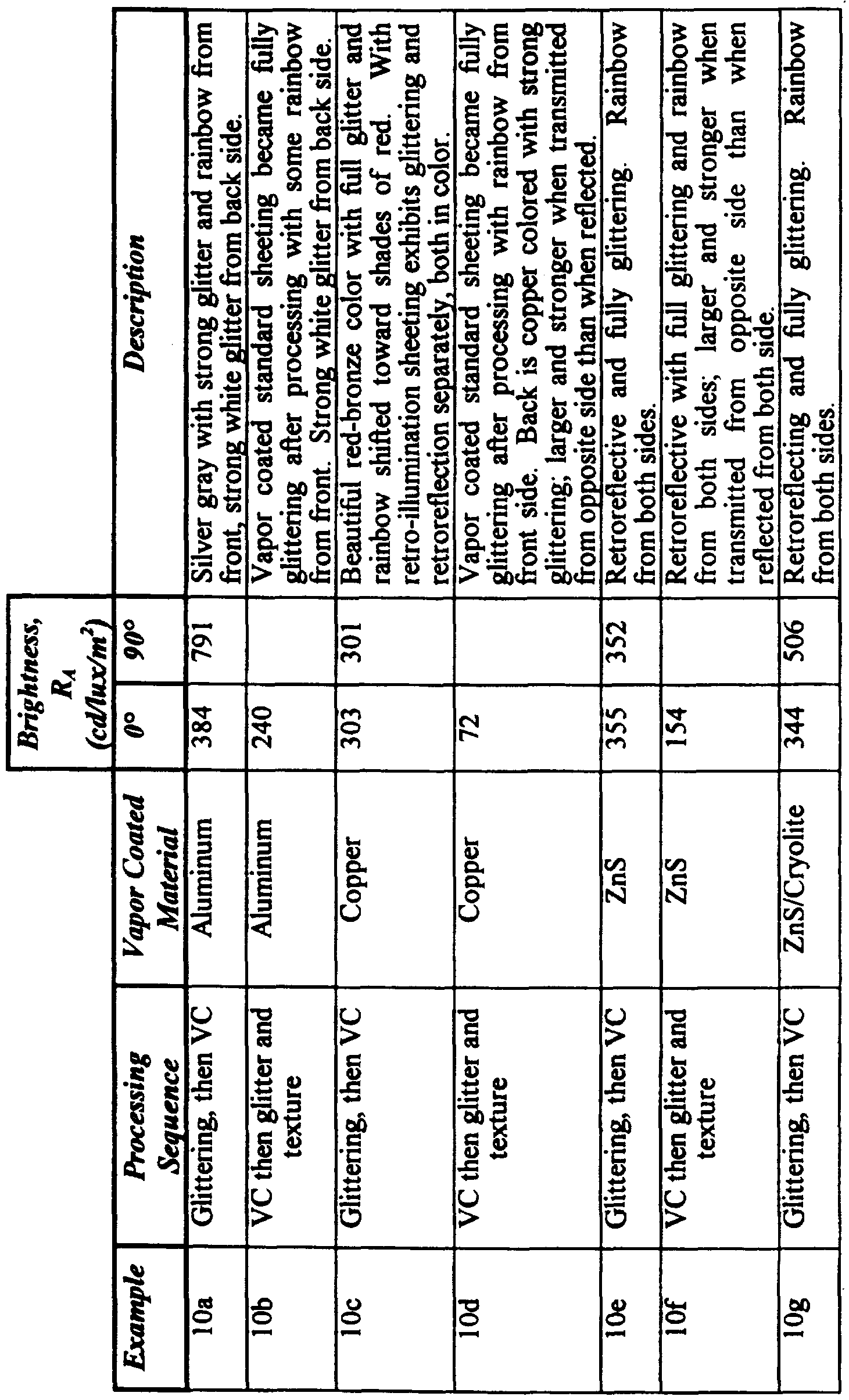

Claims
Priority Applications (3)
| Application Number | Priority Date | Filing Date | Title |
|---|---|---|---|
| EP96929865A EP0896681A1 (en) | 1996-04-30 | 1996-08-27 | Mold for producing glittering cube-corner retroreflective sheeting |
| AU69116/96A AU6911696A (en) | 1996-04-30 | 1996-08-27 | Mold for producing glittering cube-corner retroreflective sheeting |
| JP9538839A JP2000509166A (en) | 1996-04-30 | 1996-08-27 | Die for making bright corner cube retroreflective sheet |
Applications Claiming Priority (2)
| Application Number | Priority Date | Filing Date | Title |
|---|---|---|---|
| US08/640,383 US5814355A (en) | 1996-04-30 | 1996-04-30 | Mold for producing glittering cube-corner retroreflective sheeting |
| US08/640,383 | 1996-04-30 |
Publications (1)
| Publication Number | Publication Date |
|---|---|
| WO1997041464A1 true WO1997041464A1 (en) | 1997-11-06 |
Family
ID=24568024
Family Applications (1)
| Application Number | Title | Priority Date | Filing Date |
|---|---|---|---|
| PCT/US1996/014104 WO1997041464A1 (en) | 1996-04-30 | 1996-08-27 | Mold for producing glittering cube-corner retroreflective sheeting |
Country Status (9)
| Country | Link |
|---|---|
| US (1) | US5814355A (en) |
| EP (1) | EP0896681A1 (en) |
| JP (1) | JP2000509166A (en) |
| KR (1) | KR100388002B1 (en) |
| CN (1) | CN1129009C (en) |
| AU (1) | AU6911696A (en) |
| CA (1) | CA2252981A1 (en) |
| TW (1) | TW389842B (en) |
| WO (1) | WO1997041464A1 (en) |
Cited By (5)
| Publication number | Priority date | Publication date | Assignee | Title |
|---|---|---|---|---|
| US6045230A (en) * | 1998-02-05 | 2000-04-04 | 3M Innovative Properties Company | Modulating retroreflective article |
| US6282026B1 (en) | 1998-02-05 | 2001-08-28 | 3M Innovative Properties Company | Retroreflectors having two optical surfaces and varying retroreflectivity |
| NL1025360C2 (en) * | 2004-01-29 | 2006-10-24 | Dox Vako Internat B V | Applying reflective layer to plastic substrate, e.g. water repellent clothing, by hot pressing layer comprising synthetic support web, metal and glass particles to substrate |
| EP2507068B1 (en) | 2009-12-04 | 2017-05-17 | Giesecke & Devrient GmbH | Security element, value document comprising such a security element and method for producing such a security element |
| US11253933B2 (en) | 2017-02-14 | 2022-02-22 | 3M Innovative Properties Company | Non-orthogonal cube corner elements and arrays thereof made by end milling |
Families Citing this family (35)
| Publication number | Priority date | Publication date | Assignee | Title |
|---|---|---|---|---|
| US5948488A (en) * | 1996-04-30 | 1999-09-07 | 3M Innovative Properties Company | Glittering cube-corner article |
| JPH1115415A (en) * | 1997-06-16 | 1999-01-22 | Minnesota Mining & Mfg Co <3M> | Recursively reflecting sheet capable of emitting light by itself and manufacture thereof |
| US6440334B2 (en) * | 1999-06-11 | 2002-08-27 | 3M Innovative Properties Company | Method of making a retroreflective article |
| CA2384709A1 (en) * | 1999-10-04 | 2001-04-12 | 3M Innovative Properties Company | Improved continuous process for making glittering cube corner sheeting |
| US6758992B2 (en) * | 2001-02-28 | 2004-07-06 | 3M Innovative Properties Company | Process of stripe coating to produce microstructured composite articles |
| EP1390664A4 (en) | 2001-03-30 | 2008-01-02 | Univ Arizona | Materials, methods, and uses for photochemical generation of acids and/or radical species |
| WO2003014779A1 (en) * | 2001-08-09 | 2003-02-20 | Nippon Carbide Kogyo Kabushiki Kaisha | Retroreflection device |
| JP3445587B2 (en) * | 2001-09-13 | 2003-09-08 | コナミ株式会社 | Competitive rally game program |
| JP2003315516A (en) * | 2002-04-18 | 2003-11-06 | Three M Innovative Properties Co | Reflective multilayer body |
| US7140812B2 (en) * | 2002-05-29 | 2006-11-28 | 3M Innovative Properties Company | Diamond tool with a multi-tipped diamond |
| US20040045419A1 (en) * | 2002-09-10 | 2004-03-11 | Bryan William J. | Multi-diamond cutting tool assembly for creating microreplication tools |
| WO2005056275A1 (en) * | 2003-12-15 | 2005-06-23 | Multi Sign A/S | System and method for the manufacture of a film comprising a retro reflective pattern |
| EP1550546A1 (en) * | 2003-12-29 | 2005-07-06 | Mactac Europe S.A. | Process of microstructuring of a surface of a multi-layered flexible substrate, and microstructured substrate |
| US8215943B2 (en) * | 2006-06-01 | 2012-07-10 | Avery Dennison Corporation | Heat-transfer label assembly and apparatus for applying heat-transfer labels |
| US20100215794A1 (en) * | 2007-09-06 | 2010-08-26 | Entire Technology Co., Ltd. | Diffusion film molding tool & manufacturing process thereof |
| WO2009094515A2 (en) * | 2008-01-23 | 2009-07-30 | Myers Blaine E | System and method for heat energy conservation via corner reflectors |
| CN101981474A (en) | 2008-04-02 | 2011-02-23 | 3M创新有限公司 | Light directing film and method for making the same |
| EP2350710B1 (en) | 2008-10-22 | 2020-09-16 | 3M Innovative Properties Company | Retroreflective sheeting |
| EP2361396A4 (en) * | 2008-12-08 | 2018-01-24 | 3M Innovative Properties Company | Prismatic retroreflective article bearing a graphic and method of making same |
| BRPI1006713A2 (en) * | 2009-04-15 | 2019-06-18 | 3M Innovative Properties Co | retroreflective articles |
| US9140833B2 (en) | 2009-04-15 | 2015-09-22 | 3M Innovative Properties Company | Retroreflective sheeting including a low refractive index layer having a plurality of voids |
| BRPI1006654A2 (en) | 2009-04-15 | 2016-02-10 | 3M Innovative Properties Co | retroreflective optical constructions and optical films |
| US9291752B2 (en) | 2013-08-19 | 2016-03-22 | 3M Innovative Properties Company | Retroreflecting optical construction |
| EP3495134B1 (en) | 2010-04-15 | 2020-11-25 | 3M Innovative Properties Co. | Retroreflective articles including optically active areas and optically inactive areas |
| KR101954456B1 (en) | 2010-04-15 | 2019-03-05 | 쓰리엠 이노베이티브 프로퍼티즈 캄파니 | Retroreflective articles including optically active areas and optically inactive areas |
| WO2011129831A1 (en) | 2010-04-15 | 2011-10-20 | 3M Innovative Properties Company | Retroreflective articles including optically active areas and optically inactive areas |
| TWI577523B (en) * | 2011-06-17 | 2017-04-11 | 三菱麗陽股份有限公司 | Mold having an uneven structure on its surface, optical article, and manufacturing method thereof, transparent base material for surface light emitter, and surface light emitter |
| US9149958B2 (en) * | 2011-11-14 | 2015-10-06 | Massachusetts Institute Of Technology | Stamp for microcontact printing |
| US10884163B2 (en) | 2015-07-07 | 2021-01-05 | 3M Innovative Properties Company | Polyurethane layer for a light directing article |
| CN106273572A (en) * | 2016-08-31 | 2017-01-04 | 福建三昊科技有限公司 | The production technology of a kind of microprism flash of light film and microprism flash of light film |
| US10444615B2 (en) * | 2017-08-29 | 2019-10-15 | Avery Dennison Corporation | Retroreflective sheeting for projector-based display system |
| JP2019104385A (en) * | 2017-12-12 | 2019-06-27 | 株式会社ブリヂストン | Decorative body |
| CN110320546A (en) * | 2018-03-29 | 2019-10-11 | 厦门迈通光电有限公司 | Scintillator arrays and the mold and method for preparing scintillator arrays |
| CN110687625A (en) * | 2019-09-30 | 2020-01-14 | 浙江棱镜文化传媒有限公司 | Flat lens for air imaging and air imaging system |
| JP7033368B1 (en) * | 2020-08-05 | 2022-03-10 | ナルックス株式会社 | A method for manufacturing a mold for a retroreflective optical element and a method for manufacturing a retroreflective optical element. |
Citations (4)
| Publication number | Priority date | Publication date | Assignee | Title |
|---|---|---|---|---|
| US3689346A (en) * | 1970-09-29 | 1972-09-05 | Rowland Dev Corp | Method for producing retroreflective material |
| US4189209A (en) * | 1978-10-13 | 1980-02-19 | Ferro Corporation | Retroreflector of integrated light reflecting units of varying configurations |
| EP0269329A2 (en) * | 1986-11-21 | 1988-06-01 | Minnesota Mining And Manufacturing Company | Cube-corner retroreflective articles having tailored divergence profiles |
| WO1995011464A2 (en) * | 1993-10-20 | 1995-04-27 | Minnesota Mining And Manufacturing Company | Ultra-flexible retroreflective cube corner composite sheetings and methods of manufacture |
Family Cites Families (59)
| Publication number | Priority date | Publication date | Assignee | Title |
|---|---|---|---|---|
| US3010845A (en) * | 1957-05-15 | 1961-11-28 | Goodrich Co B F | Method and apparatus for decorating web or sheet material with glitter |
| US3450459A (en) * | 1965-10-24 | 1969-06-17 | Walter F Haggerty | Retroreflective device |
| US3924929A (en) * | 1966-11-14 | 1975-12-09 | Minnesota Mining & Mfg | Retro-reflective sheet material |
| US3541606A (en) * | 1967-10-16 | 1970-11-17 | Amerace Esna Corp | Reflectorized vehicles and reflectors therefor |
| US3469898A (en) * | 1967-11-20 | 1969-09-30 | Gerald Altman | Reflex reflective products and processes for their manufacture |
| US3632695A (en) * | 1970-03-05 | 1972-01-04 | Reflex Corp Canada Ltd | Making a combined lens and reflector |
| US3692731A (en) * | 1970-04-29 | 1972-09-19 | Mobil Oil Corp | Metallizing coating compositions containing coated metal flakes |
| US3697070A (en) * | 1970-06-19 | 1972-10-10 | Mobil Oil Corp | Metallizing coating compositions |
| US3810804A (en) * | 1970-09-29 | 1974-05-14 | Rowland Dev Corp | Method of making retroreflective material |
| US3988494A (en) * | 1972-04-10 | 1976-10-26 | Mobil Oil Corporation | Metallizing coating compositions |
| US3811983A (en) * | 1972-06-23 | 1974-05-21 | Rowland Dev Corp | Method for producing retroreflective sheeting |
| US3935359A (en) * | 1972-06-23 | 1976-01-27 | Rowland Development Corporation | Retroreflective sheeting and method and apparatus for producing same |
| US3830682A (en) * | 1972-11-06 | 1974-08-20 | Rowland Dev Corp | Retroreflecting signs and the like with novel day-night coloration |
| US3873184A (en) * | 1973-02-16 | 1975-03-25 | Amerace Esna Corp | Reflector with interspersed angled reflex elements |
| US3926402A (en) * | 1973-04-24 | 1975-12-16 | Amerace Corp | Pin having nonaligned cube axis and pin axis and bundle of such pins |
| US3923378A (en) * | 1973-04-24 | 1975-12-02 | Amerace Corp | Cube-corner reflector with non-aligned cube axes and element axes |
| US3987229A (en) * | 1973-11-19 | 1976-10-19 | Reneer Films Corporation | Calendered film/plastisol film laminate structure |
| FR2288005A1 (en) * | 1974-10-17 | 1976-05-14 | Greenwood William | IMPROVEMENTS MADE IN THE DECORATION PROCESSES OF PRODUCTS AND PRODUCTS OBTAINED THROUGH THESE IMPROVEMENTS |
| USRE29396E (en) * | 1975-02-18 | 1977-09-13 | Amerace Corporation | Pin having nonaligned cube axis and pin axis and bundle of such pins |
| US3992080A (en) * | 1975-06-13 | 1976-11-16 | Reflexite Corporation | Retroreflective sheet material with controlled stretch and method of making same |
| US4025159A (en) * | 1976-02-17 | 1977-05-24 | Minnesota Mining And Manufacturing Company | Cellular retroreflective sheeting |
| US4066331A (en) * | 1976-06-25 | 1978-01-03 | Beatrice Foods Co. | Cube corner type retroreflectors with improved cube corner unit relationships |
| US4349598A (en) * | 1976-12-01 | 1982-09-14 | Minnesota Mining And Manufacturing Company | High incidence angle retroreflective material |
| US4202600A (en) * | 1978-04-24 | 1980-05-13 | Avery International Corporation | Diced retroreflective sheeting |
| US4668558A (en) * | 1978-07-20 | 1987-05-26 | Minnesota Mining And Manufacturing Company | Shaped plastic articles having replicated microstructure surfaces |
| US4243618A (en) * | 1978-10-23 | 1981-01-06 | Avery International Corporation | Method for forming retroreflective sheeting |
| EP0018798B1 (en) * | 1978-11-08 | 1983-06-08 | LUCAS INDUSTRIES public limited company | Reflex reflector device |
| US4332847A (en) * | 1979-09-20 | 1982-06-01 | Relfexite Corporation | Method for compression molding of retroreflective sheeting and sheeting produced thereby |
| US4486363A (en) * | 1982-09-30 | 1984-12-04 | Amerace Corporation | Method and apparatus for embossing a precision optical pattern in a resinous sheet |
| US4478769A (en) * | 1982-09-30 | 1984-10-23 | Amerace Corporation | Method for forming an embossing tool with an optically precise pattern |
| US4601861A (en) * | 1982-09-30 | 1986-07-22 | Amerace Corporation | Methods and apparatus for embossing a precision optical pattern in a resinous sheet or laminate |
| US4588258A (en) * | 1983-09-12 | 1986-05-13 | Minnesota Mining And Manufacturing Company | Cube-corner retroreflective articles having wide angularity in multiple viewing planes |
| US4712868A (en) * | 1985-09-23 | 1987-12-15 | Minnesota Mining And Manufacturing Company | Expanded retroreflective sheet material |
| US4938563A (en) * | 1986-11-21 | 1990-07-03 | Minnesota Mining And Manufacturing Company | High efficiency cube corner retroflective material |
| US4801193A (en) * | 1988-03-04 | 1989-01-31 | Reflexite Corporation | Retroreflective sheet material and method of making same |
| US4895428A (en) * | 1988-07-26 | 1990-01-23 | Minnesota Mining And Manufacturing Company | High efficiency retroreflective material |
| US5080463A (en) * | 1989-06-21 | 1992-01-14 | Minnesota Mining And Manufacturing Company | Retroreflective security laminates with protective cover sheets |
| JPH03124754A (en) * | 1989-10-09 | 1991-05-28 | Mitsubishi Rayon Co Ltd | Impact-resistant film |
| US5202180A (en) * | 1990-02-06 | 1993-04-13 | Avery Dennison Corporation | Decorative web |
| US5264063A (en) * | 1990-05-16 | 1993-11-23 | Reflexite Corporation | Method for making flexible retroreflective sheet material |
| US5138488A (en) * | 1990-09-10 | 1992-08-11 | Minnesota Mining And Manufacturing Company | Retroreflective material with improved angularity |
| ZA918849B (en) * | 1990-12-06 | 1992-08-26 | Minnesota Mining & Mfg | Articles exhibiting durable fluorescence |
| US5084782A (en) * | 1990-12-20 | 1992-01-28 | Eastman Kodak Company | Decorative tape |
| US5152917B1 (en) * | 1991-02-06 | 1998-01-13 | Minnesota Mining & Mfg | Structured abrasive article |
| US5213872A (en) * | 1991-04-19 | 1993-05-25 | Stimsonite Corporation | Preprinted retroreflective highway sign and method for making the sign |
| US5276075A (en) * | 1991-10-30 | 1994-01-04 | Binney & Smith Inc. | Washable acrylic paint |
| JPH05209142A (en) * | 1992-01-30 | 1993-08-20 | Mazda Motor Corp | Glittering material for coating |
| US5272562A (en) * | 1993-02-05 | 1993-12-21 | Minnesota Mining And Manufacturing Company | Cube-corner retroreflective articles |
| US5362374A (en) * | 1993-08-27 | 1994-11-08 | Chang Jung Ming | Method for making decorative stickers |
| JP3590065B2 (en) * | 1993-10-20 | 2004-11-17 | ミネソタ マイニング アンド マニュファクチャリング カンパニー | Retroreflective corner cube article and method of making the same |
| US5450235A (en) * | 1993-10-20 | 1995-09-12 | Minnesota Mining And Manufacturing Company | Flexible cube-corner retroreflective sheeting |
| US5454844A (en) * | 1993-10-29 | 1995-10-03 | Minnesota Mining And Manufacturing Company | Abrasive article, a process of making same, and a method of using same to finish a workpiece surface |
| USD366365S (en) | 1994-05-11 | 1996-01-23 | Minnesota Mining And Manufacturing Company | Coated abrasive sheet article |
| US5512219A (en) * | 1994-06-03 | 1996-04-30 | Reflexite Corporation | Method of casting a microstructure sheet having an array of prism elements using a reusable polycarbonate mold |
| JP3990446B2 (en) * | 1994-09-28 | 2007-10-10 | リフレキサイト・コーポレーション | Retroreflective inclined prism structure |
| US5470058A (en) * | 1994-09-30 | 1995-11-28 | Lisco, Inc. | High visibility inflated game ball |
| US5485311A (en) * | 1995-01-06 | 1996-01-16 | Mcallister; Richard | Method of increasing retroreflective brightness in a retroreflective sheet material |
| US6143224A (en) * | 1995-05-18 | 2000-11-07 | Reflexite Corporation | Method for forming a retroreflective sheeting |
| US5592330A (en) * | 1995-05-19 | 1997-01-07 | Reflexite Corporation | Retroreflective prism arrays with formed air spheres therein |
-
1996
- 1996-04-30 US US08/640,383 patent/US5814355A/en not_active Expired - Lifetime
- 1996-08-27 JP JP9538839A patent/JP2000509166A/en not_active Ceased
- 1996-08-27 CA CA002252981A patent/CA2252981A1/en not_active Abandoned
- 1996-08-27 AU AU69116/96A patent/AU6911696A/en not_active Abandoned
- 1996-08-27 CN CN96180276A patent/CN1129009C/en not_active Expired - Fee Related
- 1996-08-27 WO PCT/US1996/014104 patent/WO1997041464A1/en not_active Application Discontinuation
- 1996-08-27 KR KR10-1998-0708649A patent/KR100388002B1/en not_active IP Right Cessation
- 1996-08-27 EP EP96929865A patent/EP0896681A1/en not_active Withdrawn
-
1997
- 1997-04-03 TW TW086104324A patent/TW389842B/en not_active IP Right Cessation
Patent Citations (4)
| Publication number | Priority date | Publication date | Assignee | Title |
|---|---|---|---|---|
| US3689346A (en) * | 1970-09-29 | 1972-09-05 | Rowland Dev Corp | Method for producing retroreflective material |
| US4189209A (en) * | 1978-10-13 | 1980-02-19 | Ferro Corporation | Retroreflector of integrated light reflecting units of varying configurations |
| EP0269329A2 (en) * | 1986-11-21 | 1988-06-01 | Minnesota Mining And Manufacturing Company | Cube-corner retroreflective articles having tailored divergence profiles |
| WO1995011464A2 (en) * | 1993-10-20 | 1995-04-27 | Minnesota Mining And Manufacturing Company | Ultra-flexible retroreflective cube corner composite sheetings and methods of manufacture |
Cited By (6)
| Publication number | Priority date | Publication date | Assignee | Title |
|---|---|---|---|---|
| US6045230A (en) * | 1998-02-05 | 2000-04-04 | 3M Innovative Properties Company | Modulating retroreflective article |
| US6282026B1 (en) | 1998-02-05 | 2001-08-28 | 3M Innovative Properties Company | Retroreflectors having two optical surfaces and varying retroreflectivity |
| NL1025360C2 (en) * | 2004-01-29 | 2006-10-24 | Dox Vako Internat B V | Applying reflective layer to plastic substrate, e.g. water repellent clothing, by hot pressing layer comprising synthetic support web, metal and glass particles to substrate |
| EP2507068B1 (en) | 2009-12-04 | 2017-05-17 | Giesecke & Devrient GmbH | Security element, value document comprising such a security element and method for producing such a security element |
| US11253933B2 (en) | 2017-02-14 | 2022-02-22 | 3M Innovative Properties Company | Non-orthogonal cube corner elements and arrays thereof made by end milling |
| US11806795B2 (en) | 2017-02-14 | 2023-11-07 | 3M Innovative Properties Company | Security articles comprising groups of microstructures made by end milling |
Also Published As
| Publication number | Publication date |
|---|---|
| KR100388002B1 (en) | 2003-08-19 |
| KR20000058224A (en) | 2000-10-05 |
| EP0896681A1 (en) | 1999-02-17 |
| CN1129009C (en) | 2003-11-26 |
| JP2000509166A (en) | 2000-07-18 |
| AU6911696A (en) | 1997-11-19 |
| CA2252981A1 (en) | 1997-11-06 |
| CN1217064A (en) | 1999-05-19 |
| TW389842B (en) | 2000-05-11 |
| US5814355A (en) | 1998-09-29 |
Similar Documents
| Publication | Publication Date | Title |
|---|---|---|
| EP0896683B1 (en) | Method of making glittering cube-corner retroreflective sheeting | |
| EP1015915B1 (en) | Glittering cube-corner retroreflective sheeting | |
| US5814355A (en) | Mold for producing glittering cube-corner retroreflective sheeting | |
| EP0896680B1 (en) | Glittering cube-corner article | |
| EP0896682B1 (en) | Formed ultra-flexible retroreflective cube-corner composite sheeting with target optical properties and method for making same | |
| CA2172272C (en) | Ultra-flexible retroreflective cube corner composite sheetings and methods of manufacture | |
| EP2715415B1 (en) | Retroreflective articles having composite cube-corners and methods of making | |
| CA2252433C (en) | Glittering cube-corner retroreflective sheeting | |
| CA2521906A1 (en) | Method of making glittering cube-corner retroreflective sheeting |
Legal Events
| Date | Code | Title | Description |
|---|---|---|---|
| WWE | Wipo information: entry into national phase |
Ref document number: 96180276.6 Country of ref document: CN |
|
| AK | Designated states |
Kind code of ref document: A1 Designated state(s): AL AM AT AU AZ BB BG BR BY CA CH CN CU CZ DE DK EE ES FI GB GE HU IL IS JP KE KG KP KR KZ LK LR LS LT LU LV MD MG MK MN MW MX NO NZ PL PT RO RU SD SE SG SI SK TJ TM TR TT UA UG UZ VN AM AZ BY KG KZ MD RU TJ TM |
|
| AL | Designated countries for regional patents |
Kind code of ref document: A1 Designated state(s): KE LS MW SD SZ UG AT BE CH DE DK ES FI FR GB GR IE IT LU MC NL PT SE BF BJ CF CG CI CM GA |
|
| DFPE | Request for preliminary examination filed prior to expiration of 19th month from priority date (pct application filed before 20040101) | ||
| 121 | Ep: the epo has been informed by wipo that ep was designated in this application | ||
| ENP | Entry into the national phase |
Ref document number: 2252981 Country of ref document: CA Ref document number: 2252981 Country of ref document: CA Kind code of ref document: A |
|
| WWE | Wipo information: entry into national phase |
Ref document number: 1996929865 Country of ref document: EP |
|
| WWE | Wipo information: entry into national phase |
Ref document number: 1019980708649 Country of ref document: KR |
|
| WWP | Wipo information: published in national office |
Ref document number: 1996929865 Country of ref document: EP |
|
| REG | Reference to national code |
Ref country code: DE Ref legal event code: 8642 |
|
| WWP | Wipo information: published in national office |
Ref document number: 1019980708649 Country of ref document: KR |
|
| WWG | Wipo information: grant in national office |
Ref document number: 1019980708649 Country of ref document: KR |
|
| WWW | Wipo information: withdrawn in national office |
Ref document number: 1996929865 Country of ref document: EP |