WO1998012449A2 - Damping system for vibrating members - Google Patents
Damping system for vibrating members Download PDFInfo
- Publication number
- WO1998012449A2 WO1998012449A2 PCT/US1997/016575 US9716575W WO9812449A2 WO 1998012449 A2 WO1998012449 A2 WO 1998012449A2 US 9716575 W US9716575 W US 9716575W WO 9812449 A2 WO9812449 A2 WO 9812449A2
- Authority
- WO
- WIPO (PCT)
- Prior art keywords
- low
- granular material
- density granular
- damping
- rotating
- Prior art date
Links
Classifications
-
- F—MECHANICAL ENGINEERING; LIGHTING; HEATING; WEAPONS; BLASTING
- F01—MACHINES OR ENGINES IN GENERAL; ENGINE PLANTS IN GENERAL; STEAM ENGINES
- F01D—NON-POSITIVE DISPLACEMENT MACHINES OR ENGINES, e.g. STEAM TURBINES
- F01D5/00—Blades; Blade-carrying members; Heating, heat-insulating, cooling or antivibration means on the blades or the members
- F01D5/12—Blades
- F01D5/14—Form or construction
- F01D5/16—Form or construction for counteracting blade vibration
-
- F—MECHANICAL ENGINEERING; LIGHTING; HEATING; WEAPONS; BLASTING
- F01—MACHINES OR ENGINES IN GENERAL; ENGINE PLANTS IN GENERAL; STEAM ENGINES
- F01D—NON-POSITIVE DISPLACEMENT MACHINES OR ENGINES, e.g. STEAM TURBINES
- F01D5/00—Blades; Blade-carrying members; Heating, heat-insulating, cooling or antivibration means on the blades or the members
- F01D5/02—Blade-carrying members, e.g. rotors
- F01D5/027—Arrangements for balancing
-
- F—MECHANICAL ENGINEERING; LIGHTING; HEATING; WEAPONS; BLASTING
- F04—POSITIVE - DISPLACEMENT MACHINES FOR LIQUIDS; PUMPS FOR LIQUIDS OR ELASTIC FLUIDS
- F04D—NON-POSITIVE-DISPLACEMENT PUMPS
- F04D29/00—Details, component parts, or accessories
- F04D29/66—Combating cavitation, whirls, noise, vibration or the like; Balancing
- F04D29/661—Combating cavitation, whirls, noise, vibration or the like; Balancing especially adapted for elastic fluid pumps
- F04D29/662—Balancing of rotors
-
- F—MECHANICAL ENGINEERING; LIGHTING; HEATING; WEAPONS; BLASTING
- F16—ENGINEERING ELEMENTS AND UNITS; GENERAL MEASURES FOR PRODUCING AND MAINTAINING EFFECTIVE FUNCTIONING OF MACHINES OR INSTALLATIONS; THERMAL INSULATION IN GENERAL
- F16F—SPRINGS; SHOCK-ABSORBERS; MEANS FOR DAMPING VIBRATION
- F16F15/00—Suppression of vibrations in systems; Means or arrangements for avoiding or reducing out-of-balance forces, e.g. due to motion
- F16F15/10—Suppression of vibrations in rotating systems by making use of members moving with the system
-
- F—MECHANICAL ENGINEERING; LIGHTING; HEATING; WEAPONS; BLASTING
- F16—ENGINEERING ELEMENTS AND UNITS; GENERAL MEASURES FOR PRODUCING AND MAINTAINING EFFECTIVE FUNCTIONING OF MACHINES OR INSTALLATIONS; THERMAL INSULATION IN GENERAL
- F16F—SPRINGS; SHOCK-ABSORBERS; MEANS FOR DAMPING VIBRATION
- F16F15/00—Suppression of vibrations in systems; Means or arrangements for avoiding or reducing out-of-balance forces, e.g. due to motion
- F16F15/32—Correcting- or balancing-weights or equivalent means for balancing rotating bodies, e.g. vehicle wheels
- F16F15/36—Correcting- or balancing-weights or equivalent means for balancing rotating bodies, e.g. vehicle wheels operating automatically, i.e. where, for a given amount of unbalance, there is movement of masses until balance is achieved
- F16F15/363—Correcting- or balancing-weights or equivalent means for balancing rotating bodies, e.g. vehicle wheels operating automatically, i.e. where, for a given amount of unbalance, there is movement of masses until balance is achieved using rolling bodies, e.g. balls free to move in a circumferential direction
-
- F—MECHANICAL ENGINEERING; LIGHTING; HEATING; WEAPONS; BLASTING
- F16—ENGINEERING ELEMENTS AND UNITS; GENERAL MEASURES FOR PRODUCING AND MAINTAINING EFFECTIVE FUNCTIONING OF MACHINES OR INSTALLATIONS; THERMAL INSULATION IN GENERAL
- F16F—SPRINGS; SHOCK-ABSORBERS; MEANS FOR DAMPING VIBRATION
- F16F15/00—Suppression of vibrations in systems; Means or arrangements for avoiding or reducing out-of-balance forces, e.g. due to motion
- F16F15/32—Correcting- or balancing-weights or equivalent means for balancing rotating bodies, e.g. vehicle wheels
- F16F15/36—Correcting- or balancing-weights or equivalent means for balancing rotating bodies, e.g. vehicle wheels operating automatically, i.e. where, for a given amount of unbalance, there is movement of masses until balance is achieved
- F16F15/366—Correcting- or balancing-weights or equivalent means for balancing rotating bodies, e.g. vehicle wheels operating automatically, i.e. where, for a given amount of unbalance, there is movement of masses until balance is achieved using fluid or powder means, i.e. non-discrete material
-
- F—MECHANICAL ENGINEERING; LIGHTING; HEATING; WEAPONS; BLASTING
- F16—ENGINEERING ELEMENTS AND UNITS; GENERAL MEASURES FOR PRODUCING AND MAINTAINING EFFECTIVE FUNCTIONING OF MACHINES OR INSTALLATIONS; THERMAL INSULATION IN GENERAL
- F16F—SPRINGS; SHOCK-ABSORBERS; MEANS FOR DAMPING VIBRATION
- F16F7/00—Vibration-dampers; Shock-absorbers
- F16F7/01—Vibration-dampers; Shock-absorbers using friction between loose particles, e.g. sand
-
- G—PHYSICS
- G01—MEASURING; TESTING
- G01M—TESTING STATIC OR DYNAMIC BALANCE OF MACHINES OR STRUCTURES; TESTING OF STRUCTURES OR APPARATUS, NOT OTHERWISE PROVIDED FOR
- G01M1/00—Testing static or dynamic balance of machines or structures
- G01M1/30—Compensating unbalance
- G01M1/32—Compensating unbalance by adding material to the body to be tested, e.g. by correcting-weights
-
- Y—GENERAL TAGGING OF NEW TECHNOLOGICAL DEVELOPMENTS; GENERAL TAGGING OF CROSS-SECTIONAL TECHNOLOGIES SPANNING OVER SEVERAL SECTIONS OF THE IPC; TECHNICAL SUBJECTS COVERED BY FORMER USPC CROSS-REFERENCE ART COLLECTIONS [XRACs] AND DIGESTS
- Y02—TECHNOLOGIES OR APPLICATIONS FOR MITIGATION OR ADAPTATION AGAINST CLIMATE CHANGE
- Y02T—CLIMATE CHANGE MITIGATION TECHNOLOGIES RELATED TO TRANSPORTATION
- Y02T50/00—Aeronautics or air transport
- Y02T50/60—Efficient propulsion technologies, e.g. for aircraft
-
- Y—GENERAL TAGGING OF NEW TECHNOLOGICAL DEVELOPMENTS; GENERAL TAGGING OF CROSS-SECTIONAL TECHNOLOGIES SPANNING OVER SEVERAL SECTIONS OF THE IPC; TECHNICAL SUBJECTS COVERED BY FORMER USPC CROSS-REFERENCE ART COLLECTIONS [XRACs] AND DIGESTS
- Y10—TECHNICAL SUBJECTS COVERED BY FORMER USPC
- Y10S—TECHNICAL SUBJECTS COVERED BY FORMER USPC CROSS-REFERENCE ART COLLECTIONS [XRACs] AND DIGESTS
- Y10S416/00—Fluid reaction surfaces, i.e. impellers
- Y10S416/50—Vibration damping features
Definitions
- Backcrround Turbomachinery is used in many applications to perform work on or extract work from both gaseous and liquid fluids.
- Examples of such machinery includes gas turbines, axial and centrifugal fans, marine and aviation propellers, fan blades, helicopter blades and tail rotors, wind turbines, and steam and hydraulic power turbines.
- This machinery by design, may contain one or more of a broad class of rotating and fixed appendages including blades, vanes, foils, and impellers depending on the needs of the particular machine. These appendages are beam-like structures, often cantilevered, and have natural frequencies of vibrations, or resonant frequencies, that are excited by mechanical vibration and fluid flow. In all turbomachinery, power is transmitted via shafts of one form or another.
- Rotating appendages such as gas turbine blades are prone to vibration at critical speeds, which leads to fatigue and eventually pre-mature, and often catastrophic, failure of the component.
- Ensembles of such blades are components of turbines used as prime movers, such as gas turbines, as well as power generators, such as hydraulic turbines. Vibration of the turbine blades is caused by a combination of dynamic effects including imbalance of the rotating system and torsional vibration of the power transmission shaft, and fluid dynamic forcing. In certain operating conditions these phenomenon conspire to excite the natural modes of vibration in the turbine blades, and if left unchecked drive the system to failure. Natural frequencies are defined as those frequencies at which an ideal, lossless system will vibrate with zero input excitation power.
- the transmission shafts there are one or more power transmission shafts to which the rotating components are attached directly or indirectly.
- the transmission shafts also have resonant frequencies, which are a function of the shaft geometry, the loading imposed by the rotating appendages, and the boundary conditions imposed by the locations of the bearings holding the shaft system in place.
- resonant frequencies are a function of the shaft geometry, the loading imposed by the rotating appendages, and the boundary conditions imposed by the locations of the bearings holding the shaft system in place.
- Resonance in the shaft is to be minimized so as to minimize wear on bearings, minimize cyclical fatigue of the shaft, and thus to increase the service life and reliability of the equipment .
- Two-plane rotor imbalance tends to excite bending motion in a plane parallel to the axis of the power transmission shaft and perpendicular to the plane of the turbine blade disc assembly.
- Misalignment of the turbine blade tends to convert radial motion of the hub into bending motion in both planes, i.e., that plane parallel to the transmission shaft and that plane parallel to the turbine blade disc assembly.
- Fluid dynamic loading is a result of vortex shedding at the trailing edge of the (rotating or fixed) blade.
- Vortex shedding frequencies vary from section to section along the length of the blade due to slight variations in the blade structure and variations of the flow velocity across the blade.
- the range of vortex shedding frequencies for any given blade can thus span a relatively broad bandwidth. If one or more natural frequencies of the blade lie within the band of vortex shedding frequencies, then the blade will be excited into motion. In ship propellers this phenomenon is known as singing propellers. It has been found that blades with relatively straight trailing edges, as is the case for many turbine blades, are more prone to singing than those with curved trailing edges. Singing continues to excite the blade until intrinsic or added damping limits the buildup of displacement amplitude. Previous treatments for vibration in turbomachinery appendages have focused on applying damping materials or mechanisms at point locations.
- the intent is to limit the maximum displacement of the component by converting the dynamic (kinetic) energy of the appendage into heat, which is innocuous in terms of the performance and service life of the machine.
- Placing damping treatments at localized points is effective if there exist large resonant system dynamics at the chosen point, which is not always true.
- previous damping treatments have most often been applied at the base of the appendages, where they attach to the rest of the machine, at the tip in the form of a shroud for the blades, and at the inner and outer shroud for vanes . Damping at the base is attractive because the primary modification to the blade or vane is in the attachment configuration and does not affect the functional shape of the foil.
- High temperature gas turbines are especially difficult to treat. In such situations complications beyond the high centrifugal force exist. Specifically, the design must deal with heat combined with the fact that low order modes of vibration are notoriously difficult to treat using passive damping methods.
- the temperature of operation in gas turbine engines for example, is in the vicinity of 1300°F, which renders useless any conventional viscoelastic polymer or resin. Previous attempts have been made to add ceramic damping layers to the external surfaces of turbine blades, but the combination of heat and high centrifugal force renders the treatment short lived.
- dynamic absorbers have been used to reduce vibration levels in many types of devices.
- a liquid has been placed within a chamber of a hollow blade.
- the liquid oscillates within the chamber, which is sized to produce a resonant frequency approximately the same as that of a dominant resonance in the blade.
- the combination of the blade resonance and the fluid resonance form, in a simplified analogy, a two degree-of -freedom system in which energy from the blade, which has low intrinsic damping is coupled to energy in the liquid, which through proper selection of viscosity, has high intrinsic damping.
- the deficiency of this approach is that the dynamic absorber formed by the liquid oscillator only extracts energy from the blade in a relatively narrow band of frequencies . Since the excitation mechanism is broadband (a combination of fluid dynamic vortex shedding and mechanical vibrations with many harmonics) then a narrowband absorber will only provide partial relief. Dynamic absorbers have also been used for damping shafts.
- a preferred embodiment of the invention is directed to the manufacture and use of hollow turbomachinery appendages and shafts that are selectively filled with a damping material.
- the manufacturing of hollow or chambered members is routine in the construction of air-cooled vanes and blades for gas turbines and similar techniques can be used for other types of members or appendages.
- Hollow transmission shafts are routinely manufactured for many applications.
- a low density granular fill material is placed within the hollow portions of the blades, and the shafts of a system having rotating members.
- Other preferred embodiments include selected distribution of fill material for stator vanes, fan blades, various types of ducted and unducted marine propellers, aviation propellers, aircraft airfoils, and others.
- the low-density granular fill can be applied without altering the shape of the structure being dampened.
- the preferred distribution of low-density granular fill in different appendages and shafts is dependent on the geometry of the material and operating conditions of the articles.
- "low density granular material" is defined as a granular material having a specific gravity of less than 1.5.
- Rotor or stator elements, or other members referenced above are often within a fluid flowing in laminar or non- laminar form relative to the element.
- the effects of fluid flow on the vibrational characteristics of the member within the flow can vary greatly, depending upon the nature of the fluid and the forces imparted by the fluid on the member. Vibrations induced by fluid flow are superposed on vibrations caused by machine imbalance and mechanical vibration. The combination of these two forcing mechanisms establish the total vibrational characteristics of the member .
- Structural resonances of an undamped beam can often be reduced 10-20 dB by damping the beam with low density granular fill.
- granular materials having specific gravities in the range of .6 to 1.5 can be used.
- the choice of fill material for any given application can be important. Specifically, matters of weight, tolerance to high temperature, cost, damping effectiveness, ease of handling, and environmental friendliness are all important.
- the most important feature can be to prevent melting of the granular material within the structure. Ceramic materials that are both porous (low-density) and have high melting points can be readily manufactured, and can serve as a treatment for passive damping of structural vibrations. Such materials maintain their integrity even at elevated temperatures.
- Ceramics are a broad class of materials usually made from clays, which are composed chiefly of the alumino- silicate minerals kaolinite, illite, and mont orillonite .
- the clays are combined with water to make thick paste slurries which are then formed into shapes and dried at relatively low temperature, less than about 200° C.
- the dried forms are then fired at temperatures in the vicinity of 1100° C to produce the ceramic material, which is resistant to abrasion, heat, and chemical corrosion.
- Various methods can be employed for producing porous granular ceramic materials with specific gravities as low as 0.2 and grain sizes of a few millimeters or less. Such material can be used as a low-density granular fill treatment in heat critical applications.
- Other materials suitable for high temperature applications include ores or refractory materials that are processed to produce light weight, low density materials such as perlite and vermiculite. These materials can be fabricated by flash heating of water bearing ore. As the water evaporates a porous material is produced that remains stable at temperatures above 800°C and is thus suitable for damping of vibration at high temperatures.
- the low sound speed of the granular material is what enables the attenuation mechanism to become active. With a specification on the rotation speed of the appendage, and other characteristics (e.g., size and material), and a knowledge of the relationship between sound speed and pressure, a granular material can be specified to provide effective damping of the vibrational modes.
- the low-density granular fill can also be solid, hollow, spherical in shape, or dendritic in shape. By mixing together two or more types of low-density granular fill having different characteristics, the sound speed and overall mass of the fill mixture can be selected. Not only is it important to choose the proper low- density granular fill material, but the choice of where to place the material is important.
- the material needs to be placed where the system dynamics are high. Certainly one way to do this is to put the material everywhere, but this leads to unnecessary weight in the total structure.
- software tools such as the Direct Global Stiffness Matrix (DGSM) method are used to construct an iterative design tool. This method is described in the paper by J. Robert Fricke and Mark A. Hayner, "Direct Global Stiffness Matrix Method for 3-D Truss Dynamics," ASME 15th Biennial Conference on Mechanical Vibration and Noise, September 17-21, 1995 the contents of which is incorporated herein by reference in its entirety.
- DGSM Direct Global Stiffness Matrix
- the effect of adding a high- loss granular fill subsystem can also be computed analytically once the subsystem loss factor, ⁇ , is known as a function of frequency.
- the optimum design cannot be computed analytically except for relatively simple systems.
- the cross - section of the structures vary and the rotating members have varying pre-stress as a function of radial position due to centrifugal forces.
- a design tool based on DGSM can provide information on the optimum placement of granular fill material, and if several materials are available, the proper choice of material in each location.
- the design tool is based on an iterative process wherein a cost function is minimized. When the minimum cost is found, then the system parameters are used to specify the preferred design of the damping system.
- the cost function can be defined in different ways for different applications. Factors such as rms velocity, weight of granular material, ease of handling, cost of material, and other criteria can be built into the cost function. Both quantitative and qualitative measures can be included.
- an iterative search through the design parameter space is performed using either deterministic non-linear search methods, such as steepest decent gradient search, or stochastic non-linear search methods, such as simulated annealing.
- the parameters in the design space can be restricted to the placement of granular fill, e.g., type and amount as a function of position in the structure, or can also include design parameters associated with the base structure, e.g., wall thickness, cross-sectional dimension, or material properties.
- the base structure say a turbine blade
- the base structure parameters can be varied as well to yield an overall system optimization based on the defined cost function.
- Direct Global Stiffness Matrix (DGSM) method which has been formulated to analyze truss-like structures, is applicable to the case of analyzing turbomachinery appendages and shafts. These structures are slender objects, that is, their cross-sectional dimensions are much smaller than their length.
- the DGSM formulation was designed to analyze assemblages of beam- like structures connected together by "welded" joints, where welded simply means the joint is in force balance and displacements are continuous.
- a turbomachinery appendage or shaft even one of varying cross-sectional geometry, can be decomposed into an assemblage of local beam-like structures, each of which has constant cross-sectional properties and pre-stress.
- any given appendage or shaft can be modeled by breaking it into a number of beam elements then assembling the elements into a whole, which is an approximation of the actual appendage or shaft. Convergence tests show when the discretization of the structure is sufficiently fine to permit close approximation to the actual dynamics of the structure being designed.
- the system can also be used in the analysis of plates, that can be represented, for example, by two overlayed orthogonal sets of beams forming a grid, and can similarly be used in the analysis of other more complex structures.
- Other forward models can be used instead of DGSM including statistical energy analysis (SEA) , finite element analysis (FEA) , and boundary element analysis (BEA) . These methods are known by those skilled in the art and can be used in the design of damping systems as described herein .
- the iterative design procedure begins. Using the cost function as a guide, design parameters are varied in each beam element according to the optimization procedure being used (deterministic or stochastic) . If there are N design parameters defining the cost function, then the objective of the optimization procedure is to find the minimum of the cost function in the N-dimensional space. If N is small, say less than 10, then deterministic methods work well. If N is large, say greater than 100, then stochastic methods work better. If N is between 10 and 100, then the preferred optimization method is a function of the complexity of the functional relationship of the cost function to the N design parameters. The more complicated the function, the more likely that deterministic methods are less accurate and that stochastic methods are used.
- the present invention provides effective damping without changing the functional form factor (shape) of the machinery.
- This damping is light weight with a specific gravity less than 1.5 and does not significantly increase requirements for static load capacity of the machinery.
- the treatment can be retrofitted to existing machinery. Low-density granular fill is effective because of its low sound speed, which is a property of the selected granular materials .
- the present invention can be applied to many types of turbomachinery appendages, including gas turbine blades and vanes, pump impellers, fan blades, marine and aviation propellers, helicopter blades and aircraft wings, wind turbine blades, and steam and hydraulic turbine blades, among others.
- the damping materials described herein can also be applied to structures that are mechanically coupled to the above systems or systems coupled through air, water or other fluids.
- the housing or other support structures for turbomachinery for example, can also be damped in accordance with the invention.
- FIG. 1 is a schematic drawing of a turbine wheel with blades, hub, shaft, and low-density granular fill.
- FIG. 2 is a plot of damping effectiveness of low- density granular fill in steel beams.
- FIG 3 is a plot of sensitivity of low-density granular fill sound speed to changes in pressure.
- FIG. 4 is a flow chart for the design method based on DGSM modeling for structural dynamics.
- FIGs . 5A and 5B are schematic drawings showing beam geometry from the side and end views, respectively, for defining the local and global coordinate systems.
- FIG. 6 is a schematic drawing of a 2-D truss.
- FIG. 7 is a schematic drawing of a joint, mass and spring model.
- FIG. 8 is a schematic drawing of a 3-D truss.
- FIG. 9 is a plot depicting stored energy in truss and total dissipated power.
- FIG. 10 is a schematic drawing of a propeller blade being modeled as beam elements.
- FIG. 11 is a side view of a rotor and stator blade.
- FIG. 12 is a flow chart of a preferred method of installing fill within a structure.
- FIGS. 13A and 13B are plots illustrating the damping characteristics of plates and beams, respectively, in accordance with the invention.
- FIG. 14 is a side view of a damped support structure for a damped rotor assembly.
- FIG. 15A is a perspective view of a damped housing in accordance with the invention.
- FIG. 15B is a graphical plot illustrating the damping characteristic of a damped housing for cooling fans.
- hollow turbine blades 16 are shown with low-density granular fill 20 for the passive control of structural vibration. Blades 16 are mounted radially on the rotor hub 30, which is connected to the power transmission shaft 14. A fluid such as air or water is moving relative to the turbine system, such as along axis 12, in either direction parallel to the shaft 12. Alternatively, the fluid flow can be in any desired direction, or can be non- laminar or highly turbulent .
- the fractional fill length of the blade (i.e. the volume of the cavity relative to the volume of the blade) can be anywhere from essentially 0% (i.e., no fill) to essentially 100% (i.e., completely filled) .
- the cavity volume is substantially filled with damping material regardless of the ratio of the volume of the cavity relative to the volume of the blade.
- the shaft 14 can likewise be partially or completely filled with low-density granular material 22 to reduce structural vibrations.
- the blades are closed at the ends to contain the low-density granular fill 20 in most applications. In some high temperature applications using metal alloy elements, openings in the elements are employed to provide cooling. Alternatively, ceramic blades can be used for high temperature applications. It is preferable in most cases to have the fill material remain stationary relative to the rotator or stator element except for the low amplitude displacements associated with the vibrations being damped.
- FIG. 2 depicts transfer accelerance measurements for an undamped 5 and a damped 6 steel box beam that is
- Damping treatment includes low-density polyethylene beads. Considerable damping occurs in the frequency range of f > 200 Hz. Note virtual elimination of cross-sectional beam resonances above 1000 Hz 7. Only a low frequency global bending mode 8 at about 100 Hz survives the low-density granular fill damping treatment and this mode is reduced by about 20dB.
- FIG. 3 depicts sound speed versus pressure for lead shot (L) 9 and ScotchliteTM glass micro-bubbles (B) 10.
- the best fit power law for the lead shot is c ⁇ p 1 /o 07 , which is very nearly the theoretical power law of 1/6 power for spherical particles.
- the best fit power law for the micro-bubbles is a power law of p raised to the exponent 1/4.2 and does not fit the theoretical prediction due to the extra compliance of the hollow spheres.
- FIG. 4 depicts the iterative method for computing the optimal design for a structure damped using low-density granular fill (LDGF) .
- the system design parameters P d for a system are, for example, the geometrical dimensions and materials, which are fixed for any given design, and are input into the Direct Global Stiffness Matrix (DGSM) system.
- DGSM Direct Global Stiffness Matrix
- the system computes a set of system dynamic responses, q, such as V rms , force, and energy density, which are used to compute the cost function F, which may also be a function of the free parameters, P ⁇ .
- the cost function is to be minimized over the free parameter space, which are the parameters that can vary for the optimization such as the amount of prestress imposed on the LDGF and the rotating appendage, density, modulus of elasticity and dimensions.
- the cost function may also be a function of design constraints, C, that are limits on the physical characteristics affecting the system, e.g., beam size must always be greater than some specified lower limit.
- the minimization procedure is achieved by iterating on the values of the free parameters using an adjustment method based on either deterministic non-linear parameter estimation, e.g., steepest decent gradient searches, or stochastic non-linear parameter estimation, e.g., simulated annealing. The optimization procedure is continued until the minimum cost function F, is found.
- the low-density granular fill materials employed in the present invention may be engineered materials for which one has control of size, shape, material properties and composition. For engineered materials, these properties are carefully controlled and customized to meet performance criteria for specific applications. These granular materials are lightweight materials of which polyethylene beads and glass micro-bubbles are just two examples. These engineered granular materials are placed inside structural components either at construction time or poured or inserted at a later time. When the surrounding structure is excited into vibration, the enclosed granular fill material is excited as well.
- the low-density granular fill materials, employed in the present invention preferably do not have significant mass relative to the host structure, nor do they necessarily have high intrinsic damping as with viscoelastic materials.
- the structural damping method and apparatus of the invention offers numerous advantages over the prior art. It is relatively easy to pour the granular material into existing structures if retrofitting is required for remediation of vibration problems. The lightweight nature of the granular material will not cause significant structural loading in most cases. Further, if the damping treatment- is considered during the design stages, there is not a significant increment in static load bearing requirements. Hence, only modest changes in the structural design are required with respect to that of a design without treatment.
- the damping treatment of the invention can be used with closed beams, e.g., hollow sections, as well as with open beams, e.g., I-beams. In the latter case, only lightweight covering panels are needed to contain the granular treatment in the vicinity of the structural beam member.
- the covering panels do not need to be structural members, i.e., they can be thin membranes such as plastic sheets or films.
- Suitable lightweight materials for practice of the invention include, but are not limited to, a plastic material such as polyethylene pellets or glass particles such as microspheres or micro-bubbles.
- polyethylene pellets are preferred because of the ease of handling and because of slightly better damping performance with respect to the glass micro-bubbles .
- glass micro-bubbles are preferred because they have a bulk specific gravity in the range of approximately 0.05-0.1 which is at least an order of magnitude less than the specific gravity of sand (not less than 1.5) and two orders of magnitude less than that of lead shot (7) .
- the choice of materials is quite broad. Such latitude opens the range of material options to include those that simultaneously offer effective damping as well as other desirable traits such as environmental friendliness, ease of handling, cost, etc.
- the fill may be an engineered material, the particle shape, size, and material properties can be tailored to meet specific performance criteria. For example, for damping frequencies as low as 200 Hz in tubular steel structures with cross-sectional dimensions of about 10 cm, low-density polyethylene (LDPE) beads which have a roughly spherical shape and a particle size ranging between about 1-5 mm in diameter are preferred with about 3 mm in diameter being most preferred.
- LDPE low-density polyethylene
- LDPE filled structures with larger cross-sectional dimensions are damped at even lower frequencies.
- glass micro-bubble beads having a spherical shape and a particle size in the range of about 150-300 microns in diameter are preferred with about 177 microns in diameter being most preferred for damping frequencies as low as 300 Hz in tubular aluminum structures with cross-sectional dimensions of about 1 cm.
- structures with a larger cross- sectional dimensions are damped at lower frequencies.
- the damping treatment of the present invention is more effective at lower frequencies than conventional treatments such as constrained layer damping.
- the low-density granular fill permits attenuation of vibrations at frequencies corresponding to a few bending wavelengths in the structure, which are often troublesome.
- the frequencies of these low order modes are determined by the structural dimensions and material properties. In many cases, these modes occur at a few hundred Hertz, and it has been shown that LDGF is effective in reducing the resonant dynamics by 10-20dB at such frequencies.
- the size of the bead treatment particles must be small enough to be easily accommodated by the structure.
- the beads should be sized such that the voids containing the beads are at least an order of about ten times the dimension of the bead diameter.
- the beads may be designed for optimum performance. For example, if high temperature tolerance is essential as it is for gas turbines, porous ceramic beads having a roughly spherical shape and a particle size in the range of about 0.1 to 1.0 mm in diameter are preferred with about 0.5 mm in diameter being most preferred.
- low frequency damping is needed in small structures and heat is not a problem, such as with light aircraft propeller blades
- low-density polyethylene (LDPE) beads having a highly irregular, dendritic (needlelike) shape with a nominal diameter of about 2 mm are preferred as they have a lower sound speed.
- the lowest frequency for which these treatments are effective is dependent on the size of the structure, larger structures being damped to lower requencies. It has been shown, however, that resonant frequencies down to about 200 Hz are effectively damped using the low-density granular ill treatment of this invention. Damping to lower frequencies depends on the particulars of the structure and treatment design. Damping at frequencies in the range of about 100 Hz - 500 Hz can now be accomplished using the present invention without the additional cost and design constraints imposed by constrained layer damping.
- the present invention does not rely on the mass loading effect as known in the prior art, nor does it rely primarily on the high intrinsic attenuation of bulk viscoelastic polymer materials.
- the low-density granular material or the "beads" in the present invention do not necessarily need to be spherical in shape. What is important is that the material be granular so that the bulk wave speed is low. With a low wave or sound speed and hence a small wavelength, any small intrinsic attenuation in the material, non-linear hysteresis due to deformation of the material, or frictional losses between grains of the material will provide effective damping of the structural vibration.
- the Direct Global Stiffness Matrix (DGSM) method can also be employed to analyze rotating members so that the correct amount and location of low-density granular fill can be determined relative to the members.
- DGSM Direct Global Stiffness Matrix
- the fundamental building block for the DGSM method is the beam element in a truss structure.
- E Young's modulus
- A cross- section
- the beam geometry shown in FIGs . 5A and 5B is used throughout to define the local coordinate system within which the beam displacements, rotations, forces, and moments are referenced .
- One dimensional compression waves in a beam are called quasi-longitudinal waves. These waves satisfy the 1-D wave equation
- A is the beam cross-section area
- Equation (2) and Equation (4) one may now write a 2x2 system of equations in local coordinates relating the beam amplitudes u * and u to the values of beam displacement, u, and force, f x as
- Equation (8) and Equation (9) one may write another 2x2 matrix, this one for the torsional excitation in the beam. Specifically,
- Equation (16) Using Equation (13) to Equation (16) produces a 4x4 matrix expressing the flexural excitation on a beam as a function of displacements, rotations, forces, and moments along the beam. In particular, this becomes
- EI z k B 2 e B -EI z k 2 e B ⁇ EI z k B 2 e "' -EI z k B 7 e ⁇
- rP ⁇ are each 6x12 matrices of coefficients, which are complex constants for a given frequency, beam material, and beam geometry. Similarly, the equations with forces and moments on the right hand side can be gathered. These may be written
- the C° , L are each 6x12 matrices of constant complex coefficients.
- K is a block stiffness matrix of the form
- the z-axis unit vector may be derived by using the properties of the cross-product as
- M j is the number of beams terminating at joint j .
- the other condition that is enforced by a welded joint is one of dynamic equilibrium. Specifically, there must be a net force and moment balance at the joint. The mathematical statement of this condition may be written
- Equation (34) and Equation (35) are enforced implicitly by summing the stiffness from all the beams terminating at each joint.
- the force contribution of the first beam is .? x - f ⁇ 1J ⁇ , where .( ⁇ is the joint displacement.
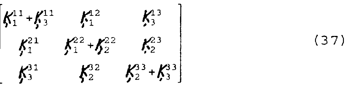
- the assembly of the global stiffness matrix closely follows the assembly of finite element static stiffness matrices. All the joints of the truss must be numbered and the beams terminating at each joint must be identified. After this is done, the contributions to the global stiffness matrix due to each beam at each joint must be determined. It is illustrative to see the global matrix constructed using a concrete example. Consider the simple 2-D truss shown in FIG. 6. The stiffness matrix for each beam relates the displacements and forces of the two joints at either end. In particular, say for beam B l t the stiffness matrix may be written
- This global stiffness matrix then is used to relate the externally applied forces and moments, 7 ert , to the unknown
- the extra (complex) stiffness at the joint due to the mass -spring system may be written in each degree of freedom as
- stiffness matrix Jj is symmetric positive-definite, which guarantees that no pivoting is required when solving the system
- stiffness matrix JjT will be quite sparse, since most beams and joints are not nearest neighbors, as is the case for the sample 2-D truss configuration in FIG. 6.
- fast sparse matrix solvers may be used to efficiently compute the beam displacements and rotations.
- spectral superposition of the different harmonic solutions may be accomplished through Fourier synthesis.
- the Direct Global Stiffness Matrix method has been used to analyze the dynamics of a 3-D truss, which is shown in FIG. 8.
- the structure is made of 6061 T6 aluminum tubing struts with an outside diameter of 1.27 cm and a wall thickness of 0.165 cm.
- the material density is 2700 kg/m 3 and the Young's modulus is 6.89xl0 10 N/m 2 .
- the relative performance of each of these damping treatments is evaluated to provide a guide to the design of an actual full-scale truss structure.
- the analytical quantities are energy stored, F s , and power lost to damping, ⁇ d l in the truss. Physically one may think of these quantities in terms of defining a time-constant for the truss structure. Suppose a continuous signal had been applied to the truss for a long time with all initial transients having settled out. There will be some kinetic energy stored in the truss dynamics and some potential energy stored in the truss elasticity.
- the truss is drawing power from the driving source and delivering this power either to heat, through absorption mechanisms in the truss itself, or to radiation loss into the air surrounding the truss .
- This power must be exactly balanced by the power delivered by the source for a steady state condition. If the source were suddenly turned off, the stored energy in the truss would bleed out of the system via the dissipation mechanisms.
- the rate at which the diminution of stored energy occurs is exactly the energy decay rate of the truss system and may be represented mathematically as
- the broadband energy decay rate is defined as
- the steady- state input power at each of the drive -points is computed. This may be computed as the time averaged product of the applied force at the drive -point and the associated joint velocity.
- the RMS power may then be written compactly as , 91
- the energy decay rate is not sufficient to act as a performance metric on its own.
- What is not included in the metric is a measure of the engineering cost for a given damping treatment. Specifically, a weight penalty and a penalty for engineering difficulty can be considered. Although these are not analytical quantities, they must be included in the performance metric in some way.
- the penalties are incorporated as factors on a scale from 1 to 5, with 1 being "good” in a normalized sense and 5 being "bad” .
- Table 2 shows the penalties proposed for each of the damping treatments, including the dynamic absorbers, even though they are not included in the analysis here. It is felt that the dynamic absorbers are sufficiently well known that by including them in the table, a sense of perspective is provided on the penalty values selected for the beam and joint treatments.
- the above DGSM approach can simulate the dynamics of arbitrary 3-D truss configurations and has a number of advantages over existing techniques. These advantages include fast solutions for the global displacement of truss joints and the ability to compute the wave amplitudes of the different wave types on each beam. Perhaps the most significant advantage is that the solution to the system of equations is, in fact, a harmonic Green's function, which may be used repeatedly to compute the solution for the truss motion for an arbitrary combination of applied forces and moments to the truss joints. This approach is possible because the dynamics are represented as linear and superposition of elemental forcing solutions is an accurate approximation. Damping performance is quantified, thus permitting the designer to make informed decisions about where and how much damping to use to achieve a given level of performance.
- the loss factor m rotating appendages is a function of rotation speed, ⁇ , bulk modulus of the granular material, £ g , bulk density of the granular material, p , and geometry of the material placement, x .
- the design of a low vibration rotating appendage requires that the appendage have high damping at frequencies that can be excited by either mechanical dynamics, e.g., vibrations from imbalance and harmonics, or fluid dynamics, e.g., vortex shedding at the Strouhal frequency matching a structural appendage resonance.
- a robust design is one that operates free of large vibrational dynamics over a broad range of operating conditions. This requirement must be achieved simultaneously with considerations of weight and cost.
- a methodology to develop such designs has already been discussed in the context of Figure 4, and a detailed presentation of the Direct Global Stiffness Matrix (DGSM) method used to represent a dynamic system of beamlike elements has been presented. In the case of rotating members, however, a modification to the DGSM is made. The flexural bending equations are modified to include tension in the beam elements.
- DGSM Direct Global Stiffness Matrix
- Equation (11) which is the classical Euler- Bernoulli bending beam equation. Tension may be added to the beam to form what is called a stiff -string equation. Specifically,
- Equation (49) There are four solutions to Equation (49) , namely
- Equation (13) The difference between the solution as written in Equation (52) and that written in Equation (13) is the fact that the wavenumber is now a function of tension in the beam element. If tension is reduced to zero, then ⁇ reduces to zero and the stiff-string wavenumber reduces to
- Equation (12) a beam bending equation has been derived for use in the DGSM method when the beam elements are in tension, which occurs when the beam is subjected to centrifugal forces.
- the solution, as written in Equation (52) can be used to assemble the global stiffness matrix in the DGSM method.
- the representation includes physical characteristics that are specific to the rotating appendage problem.
- a physical propeller blade or member 40 rotating about a pivot point 50 is represented as an assemblage of four elements 42, 44, 46 and 48.
- the elements are located between radii R 0 , R ⁇ ; R 2 , R 3 and R,, .
- Propeller blade 40 has three cavities 41, 43 and 45 which are located between radiuses R 0 , R x , R 2 and Rj .
- the selection of four elements in FIG. 10 is purely for illustrative purposes, and the actual number of elements are determined by convergence tests on successively finer approximations. Certain salient features are illustrated in FIG. 10. Specifically, the beam elements 42, 44, 46 and 48 do not necessarily have to be of equal length. This freedom is inherited from the non-rotating DGSM representation.
- the calculation of the tension is done automatically for a given geometry of the elements and a rotation speed, ⁇ .
- Damping of the beam member is achieved by the placement of granular material 47 within individual beam elements 42, 44 and 46 by filling cavities 41, 43 and 45 with the granular material 47.
- the damping loss factor for a given material, rotation speed, and fill geometry is determined by interpolation from a lookup table based on experimental results for that material . In general the damping loss factor can be written as
- ⁇ p is the apparent hydrostatic pressure imposed on the granular material due to centrifugal forces
- E is the bulk Young's modulus of the granular material
- p_ is the bulk density
- x represents the geometric description
- cavities 41, 43 and 45 have been depicted in Fig. 10 to be elongate cavities which are positioned along the longitudinal axis of propeller blade 40, alternatively, cavities 41, 43 and 45 can be positioned perpendicular to the longitudinal axis. In addition, cavities 41, 43 and 45 can be replaced by a single elongate cavity extending along the longitudinal axis of propeller blade 40.
- the DGSM program can be used for either fixed (non- rotating) or rotating appendages in the design cycle illustrated in Figure 4.
- both fixed and rotating beam elements can be incorporated into a single representation.
- An example of this is the assemblage illustrated in Figure 11.
- the shaft 52, support structure 54 and stator 58 are represented as static elements, since centrifugal forces are not dominant if the whirling of the shaft 52 is ignored.
- the blades 56 are represented with rotating beam (application of method to plates made up of beams criss crossing) elements as previously discussed.
- step 60 the location for installing the fill is determined in the manner described above.
- step 62 a bag (e.g. liner 15 in Fig. 1) or container formed from a polymer, for example, and having a geometry corresponding to the desired distribution for the fill is filled with granular fill, evacuated and sealed.
- the bag containing the granular fill is then installed within the structure at the desired location in step 64.
- the container can be rigid or flexible depending upon the needs of a particular application. For systems that are designed for use with the damping system of the present invention, this modular manufacturing technique can improve safety by minimizing exposure to the granular fill and improve efficiency.
- Vermiculite is an agricultural, construction, and refractory material made by flash heating an ore containing a small percentage of water. The water expands and produces a light weight granular material able to tolerate high temperatures.
- Preferred processing of vermiculite involves grading particle size to be uniform, and less than 2mm in diameter preferably in the range of about 1mm diameter .
- Perlite is a volcanic glass or refractory material that is manufactured in a manner much the same as vermiculite. A water bearing ore is flash heated to about 870 n C or more, which causes the water to vaporize and produce a porous, light weight material. Perlite is used in agriculture, construction, and refractory applications and tolerates temperatures up to about 1100°C. Preferred processing for perlite involves milling and grading the particle size to be less than 2mm, and preferably less than about 1 mm in diameter. The specific gravity of agricultural perlite is about 0.097 with a large particle size distribution. Milling and sifting through a 1.45mm screen produces a perlite material with a specific gravity of about 0.2.
- Porous ceramic granules can be manufactured as an absorbent for liquids in a variety of applications.
- the manufacturing process is described in U.S. Patent No. 5,177,036 entitled “Ceramic material", the entire contents of which is incorporated herein by reference.
- the ceramic beads can range in size from l-5mm and have a bulk specific gravity of 0.2 to 0.7.
- the manufacturing process requires that the beads be fired to a temperature of 1100°c, which makes them stable in elevated temperature applications. Glass microspheres are used because of their light weight and high strength under static pressure. 3M makes this product under the tradename ScotchliteTM.
- the micro-spheres are made of glass and are stable at moderately high temperatures of several hundred degrees Fahrenheit.
- the commercial product made by 3M is available in several different sizes and grades.
- the glass micro-spheres can be used in their manufactured form, but handling of the material is difficult since it becomes airborne so easily due to its light weight and small particle size.
- processing of the manufactured material involves making a thick paste or slurry of the micro-spheres and a volatile liquid with or without adhesives . After the material is in place, modest heat and/or a vacuum is applied to accelerate volatilization of the liquid, which is driven from the mixture leaving the micro-spheres behind. The temperature at which the component is treated depends on the volatile liquid.
- micro-sphere cake Use of water leaves the micro-spheres in a semi-solid cake, even without any adhesives added.
- the formation of the micro-sphere cake reduces the occurrence of airborne particulates and reduces the nuisance factor if the material is intentionally or accidentally released from the part in which it is placed.
- an alcohol volatile in which trace amounts of shellac were dissolved can -be used. When the alcohol is volatilized, the shellac is left behind to enhance surface adhesion between the micro-sphere particles.
- Other volatile liquids and mild adhesives can be used for specific applications.
- LDPE low-density polyethylene
- FIG. 13A An experiment using low-density polyethylene (LDPE) beads in contact with an aluminum plate produced the results shown in the attached FIG. 13A.
- the plate was 10 " x 15 l ⁇ " and 1mm thick.
- Three transfer accelerance measurements were averaged to produce an average response for the plate with and without low-density granular fill (LDGF) damping.
- LDGF low-density granular fill
- the plate was left bare .
- a pocket made of shrink wrap material was formed on one side of the plate and filled with LDPE beads. The top of the pocket was sealed with tape and the shrink wrap was heated, causing it to shrink and force the LDPE beads against the side of the plate.
- FIG. 13A shows the results of the two experiments with the light line representing the undamped plate response and the heavy line representing the damped response.
- the transfer accelerance of the plate is reduced by up to 30 dB when the plate is damped.
- FIG. 13B the drive point accelerance response of a tubular aluminum beam is shown with and without damping.
- the beam has an O.D. of 12.7 mm and an I.D. of 9.3 mm and is 0.46 m long. It is suspended using elastic bands with a suspension frequency of about 7 Hz, which simulates a free beam response .
- Drive point accelerance was measured at one end of the empty beam and the result is shown as the light line in Figure 13B.
- the beam was filled with milled and screened perlite and the drive point accelerance measurement repeated.
- the heavy line in FIG. 13B shows the result.
- the resonant peaks of the undamped system are reduced by up to 15dB relative to those of the undamped response .
- FIGs. 13A and 13B show the effects of the use of LDGF damping on such structures.
- LDGF treatment of the vibrating component results in a dramatic reduction of the vibrating levels.
- FIG. 14 An example of such a structure is shown in FIG. 14 where the rotating shaft 52, or a plurality of rotating elements, of a piece of turbo achinery is coupled to a base structure or housing 57 through a bearing assembly 55 and possibly through direct excitation from the fluid flow.
- the base structure 57 is, in turn, coupled to other structures such as support beams 59, which are themselves set into vibration.
- the vibration level of any given component is ultimately driven from rotating machinery or fluid flow even though neither force is acting directly on the component. In many cases, however, it is important to reduce the vibration levels of such remote components, and use of LDGF is effective to this end.
- the power dissipated in the structure , P D may be written as a function of the structural loss factor , ⁇ p r as
- tu frequency in radians per second
- m " is the mass per unit area
- S is the surface
- ⁇ v 2 > is the mean- square velocity of the structure.
- Equation (56) Equation (57)
- Equation (57) For a given input power, which is essentially independent of any structural or radiation damping, an increase in the structural loss factor, ⁇ D must be offset by a reduction in the mean-square velocity, ⁇ v 2 > . With a reduction in mean-square velocity, the radiated acoustic power P R , will reduce by virtue of Equation (57) .
- LDGF damping treatments are specifically designed to increase the structural loss factor, 7 .
- increases by an order of magnitude or more are not uncommon as shown in Figure 13A and Figure 13B.
- Equation (59) Further insight can be developed by combining Equation (59) and Equation (57) to produce a single equation relating total available input power, P-, and the radiated acoustic power, P R , ;
- the radiation loss factor, ⁇ R is always less than the structural loss factor, ⁇ O , and usually much less.
- the radiated acoustic power can be approximated by
- the system is a commercial electronics enclosure 60 excited by three DC brushless fans 62, 64, 66 running at about 1750 rpm.
- the fans produce force fluctuations on the panel 74 to which they are attached, and these vibrations are coupled throughout the system and result in force fluctuations on the base plate 72 of the equipment.
- the force fluctuations in the example illustrated in FIG. 15B were measured at each of three mount points upon which the equipment can sit.
- the circle symbols in FIG. 15B show the averaged force autospectrum of the equipment prior to any modification.
- the equipment was modified so as to incorporate panels containing LDGF material on two sides 70 and the base 72.
- the fans are still forcing an unmodified panel at the front end of the enclosure.
- the housing 60 can be an acoustic loudspeaker having a bass transducer 64, a mid-range transducer 66 and a high frequency transducer 62 mounted on a single panel 74.
- the four side panels, the top and the bottom can have the damping materials described herein mounted thereon or used to fill internal panel cavities. Damping pads 68 having the low density granular fill material therein can be attached to the bottom panel 72 of the speaker to reduce transmission of vibration from the speaker housing 60 to the floor or other support surface on which the housing is situated.
- Damping pads can also be attached to internal or external surfaces of a structure and which can be positioned to partially cover the surface.
- the pads 68 can include a low density granular fill within a plastic bag or film and can be attached with an adhesive such as a single or double sided adhesive tape.
Abstract
Description


Claims
Priority Applications (4)
| Application Number | Priority Date | Filing Date | Title |
|---|---|---|---|
| AU45838/97A AU4583897A (en) | 1996-09-17 | 1997-09-17 | Damping system for vibrating members |
| EP97944314A EP0927312A2 (en) | 1996-09-17 | 1997-09-17 | Damping system for vibrating members |
| CA002266520A CA2266520A1 (en) | 1996-09-17 | 1997-09-17 | Damping system for vibrating members |
| US09/169,432 US6224341B1 (en) | 1996-09-17 | 1998-10-09 | Damping systems for vibrating members |
Applications Claiming Priority (4)
| Application Number | Priority Date | Filing Date | Title |
|---|---|---|---|
| US2623496P | 1996-09-17 | 1996-09-17 | |
| US60/026,234 | 1996-09-17 | ||
| US08/731,251 | 1996-10-11 | ||
| US08/731,251 US5820348A (en) | 1996-09-17 | 1996-10-11 | Damping system for vibrating members |
Related Parent Applications (1)
| Application Number | Title | Priority Date | Filing Date |
|---|---|---|---|
| US08/731,251 Continuation-In-Part US5820348A (en) | 1996-09-17 | 1996-10-11 | Damping system for vibrating members |
Related Child Applications (1)
| Application Number | Title | Priority Date | Filing Date |
|---|---|---|---|
| US09/169,432 Continuation US6224341B1 (en) | 1996-09-17 | 1998-10-09 | Damping systems for vibrating members |
Publications (2)
| Publication Number | Publication Date |
|---|---|
| WO1998012449A2 true WO1998012449A2 (en) | 1998-03-26 |
| WO1998012449A3 WO1998012449A3 (en) | 1998-07-02 |
Family
ID=26700951
Family Applications (1)
| Application Number | Title | Priority Date | Filing Date |
|---|---|---|---|
| PCT/US1997/016575 WO1998012449A2 (en) | 1996-09-17 | 1997-09-17 | Damping system for vibrating members |
Country Status (5)
| Country | Link |
|---|---|
| US (2) | US5820348A (en) |
| EP (1) | EP0927312A2 (en) |
| AU (1) | AU4583897A (en) |
| CA (1) | CA2266520A1 (en) |
| WO (1) | WO1998012449A2 (en) |
Cited By (11)
| Publication number | Priority date | Publication date | Assignee | Title |
|---|---|---|---|---|
| US6224341B1 (en) | 1996-09-17 | 2001-05-01 | Edge Innovations & Technology, Llc | Damping systems for vibrating members |
| EP1098069A2 (en) | 1999-11-05 | 2001-05-09 | ROLLS-ROYCE plc | A particle vibration damper |
| FR2819295A1 (en) * | 2001-01-11 | 2002-07-12 | Rolls Royce Plc | TURBOMACHINE BLADE |
| EP1878871A1 (en) * | 2006-07-13 | 2008-01-16 | Siemens Aktiengesellschaft | Reduction of the amplitude of rotor flexural vibrations |
| GB2450936A (en) * | 2007-07-13 | 2009-01-14 | Rolls Royce Plc | Bladed rotor balancing |
| DE102009010185A1 (en) * | 2009-02-23 | 2010-08-26 | Mtu Aero Engines Gmbh | Gas turbine engine |
| DE102011008695A1 (en) * | 2011-01-15 | 2012-07-19 | Mtu Aero Engines Gmbh | A method of generatively producing a device with an integrated damping for a turbomachine and generatively manufactured component with an integrated damping for a turbomachine |
| WO2013163048A1 (en) | 2012-04-24 | 2013-10-31 | United Technologies Corporation | Airfoil with powder damper |
| CN105865643A (en) * | 2015-02-11 | 2016-08-17 | 基德科技公司 | Sensor with vibration damping |
| WO2017205080A1 (en) * | 2016-05-23 | 2017-11-30 | Vibracoustic North America L.P. | Particle damper system and method |
| FR3058767A1 (en) * | 2016-11-14 | 2018-05-18 | Safran Helicopter Engines | VIBRATION DAMPER FOR A TURBOMACHINE ROTOR BLADE |
Families Citing this family (97)
| Publication number | Priority date | Publication date | Assignee | Title |
|---|---|---|---|---|
| US6237302B1 (en) * | 1998-03-25 | 2001-05-29 | Edge Innovations & Technology, Llc | Low sound speed damping materials and methods of use |
| US6056259A (en) * | 1998-04-04 | 2000-05-02 | Sperry Marine Inc. | Tuned vibration noise reducer |
| US6378504B1 (en) * | 1999-06-10 | 2002-04-30 | Aisan Kogyo Kabushiki Kaisha | Reduced vibration fuel supply systems |
| US6551057B1 (en) | 1999-11-22 | 2003-04-22 | General Electric Company | Damped torque shaft assembly |
| WO2001049975A1 (en) | 2000-01-06 | 2001-07-12 | Damping Technologies, Inc. | Turbine engine damper |
| US6827551B1 (en) | 2000-02-01 | 2004-12-07 | The United States Of America As Represented By The Administrator Of The National Aeronautics And Space Administration | Self-tuning impact damper for rotating blades |
| US6435470B1 (en) * | 2000-09-22 | 2002-08-20 | Northrop Grumman Corporation | Tunable vibration noise reducer with spherical element containing tracks |
| US6381196B1 (en) | 2000-10-26 | 2002-04-30 | The United States Of America As Represented By The Secretary Of The Navy | Sintered viscoelastic particle vibration damping treatment |
| IT1316041B1 (en) * | 2000-12-22 | 2003-03-26 | Umbra Cuscinetti Spa | SCREW SHAFT FOR BALL CIRCULATION WITH INCREASED DIVIBRATION FREQUENCY AND IMPROVED VIBRATION DISSIPATION. |
| JP3400787B2 (en) * | 2000-12-26 | 2003-04-28 | 住友ゴム工業株式会社 | How to correct tire imbalance |
| ATE381644T1 (en) * | 2001-10-05 | 2008-01-15 | Emerson Electric Co | NOISE-REDUCED FOOD LEFT DISPOSAL DEVICE |
| US6768938B2 (en) * | 2001-11-16 | 2004-07-27 | Goodrich Pump & Engine Control Systems, Inc. | Vibration monitoring system for gas turbine engines |
| US6712059B2 (en) * | 2002-02-28 | 2004-03-30 | Robert Lee Donovan | Finned vibration damper for archery bow |
| US6688989B2 (en) | 2002-04-25 | 2004-02-10 | Acushnet Company | Iron club with captive third piece |
| US6736423B2 (en) * | 2002-07-15 | 2004-05-18 | Trw Vehicle Safety Systems Inc. | Apparatus and method for damping vibration of a vehicle part |
| GB2391270B (en) * | 2002-07-26 | 2006-03-08 | Rolls Royce Plc | Turbomachine blade |
| DE10235397A1 (en) * | 2002-08-02 | 2004-02-19 | Schefenacker Vision Systems Germany Gmbh & Co. Kg | Vibration damper for an automobile, e.g. at the rear view mirror, is composed of loose granules within a holder matched to the vibration frequencies to suppress rattles |
| US6743117B2 (en) | 2002-09-13 | 2004-06-01 | Acushnet Company | Golf club head with face inserts |
| US6814543B2 (en) | 2002-12-30 | 2004-11-09 | General Electric Company | Method and apparatus for bucket natural frequency tuning |
| DE10341759A1 (en) * | 2003-09-10 | 2005-04-21 | Gen Electric | Wind turbine with external sound enclosure |
| WO2005050616A1 (en) | 2003-10-27 | 2005-06-02 | General Electric Company | Acoustic impedance element for a wind turbine |
| US6955250B2 (en) * | 2003-12-03 | 2005-10-18 | Honeywell International Inc. | Apparatus for damping vibration using macro particulates |
| US7334998B2 (en) * | 2003-12-08 | 2008-02-26 | The United States Of America As Represented By The Administrator Of The National Aeronautics And Space Administration | Low-noise fan exit guide vanes |
| EP1566519A1 (en) * | 2004-02-23 | 2005-08-24 | Siemens Aktiengesellschaft | High temperature resisting component for a fluidic machine and fluidic machine using this component. |
| US20050194210A1 (en) * | 2004-03-08 | 2005-09-08 | The Boeing Company | Apparatus and method for aircraft cabin noise attenuation via non-obstructive particle damping |
| US7621435B2 (en) | 2004-06-17 | 2009-11-24 | The Regents Of The University Of California | Designs and fabrication of structural armor |
| US7147437B2 (en) * | 2004-08-09 | 2006-12-12 | General Electric Company | Mixed tuned hybrid blade related method |
| US20120135272A1 (en) | 2004-09-03 | 2012-05-31 | Mo-How Herman Shen | Method for applying a low residual stress damping coating |
| US20080124480A1 (en) * | 2004-09-03 | 2008-05-29 | Mo-How Herman Shen | Free layer blade damper by magneto-mechanical materials |
| EP1658966A1 (en) | 2004-11-17 | 2006-05-24 | General Electric Company | Damping material, damping arrangement and method for designing a damping arrangement |
| BRPI0610803A2 (en) * | 2005-05-13 | 2010-07-27 | Tracy Livingston | structural tower |
| US7278830B2 (en) * | 2005-05-18 | 2007-10-09 | Allison Advanced Development Company, Inc. | Composite filled gas turbine engine blade with gas film damper |
| JP4616077B2 (en) * | 2005-05-25 | 2011-01-19 | ジーイー・メディカル・システムズ・グローバル・テクノロジー・カンパニー・エルエルシー | Magnetic resonance imaging system |
| US7270517B2 (en) * | 2005-10-06 | 2007-09-18 | Siemens Power Generation, Inc. | Turbine blade with vibration damper |
| US7360997B2 (en) * | 2005-10-06 | 2008-04-22 | General Electric Company | Vibration damper coating |
| CA2635656C (en) * | 2005-12-30 | 2014-07-08 | Tracy Livingston | Lifting system and apparatus for constructing wind turbine towers |
| US7527477B2 (en) | 2006-07-31 | 2009-05-05 | General Electric Company | Rotor blade and method of fabricating same |
| US7866949B2 (en) * | 2006-08-24 | 2011-01-11 | General Electric Company | Methods and apparatus for fabricating a rotor for a steam turbine |
| US8069634B2 (en) | 2006-10-02 | 2011-12-06 | General Electric Company | Lifting system and apparatus for constructing and enclosing wind turbine towers |
| US7721844B1 (en) | 2006-10-13 | 2010-05-25 | Damping Technologies, Inc. | Vibration damping apparatus for windows using viscoelastic damping materials |
| US8082707B1 (en) | 2006-10-13 | 2011-12-27 | Damping Technologies, Inc. | Air-film vibration damping apparatus for windows |
| EP2094968B1 (en) * | 2006-12-20 | 2013-10-02 | Vestas Wind Systems A/S | A wind turbine comprising a torsional vibration absorber |
| US7381261B1 (en) | 2006-12-21 | 2008-06-03 | United States Gypsum Company | Expanded perlite annealing process |
| EP1980715A1 (en) * | 2007-04-13 | 2008-10-15 | Siemens Aktiengesellschaft | Damping of vibrations in blades and guide vanes with grains |
| GB2450934B (en) * | 2007-07-13 | 2009-10-07 | Rolls Royce Plc | A Component with a damping filler |
| GB2450935B (en) * | 2007-07-13 | 2009-06-03 | Rolls Royce Plc | Component with internal damping |
| GB2450937B (en) * | 2007-07-13 | 2009-06-03 | Rolls Royce Plc | Component with tuned frequency response |
| US8240120B2 (en) * | 2007-10-25 | 2012-08-14 | United Technologies Corporation | Vibration management for gas turbine engines |
| US8381463B2 (en) | 2007-10-30 | 2013-02-26 | Martin A. Muska | Energy absorbing system for safeguarding structures from disruptive forces |
| US8267662B2 (en) * | 2007-12-13 | 2012-09-18 | General Electric Company | Monolithic and bi-metallic turbine blade dampers and method of manufacture |
| US8292214B2 (en) * | 2008-01-18 | 2012-10-23 | The Boeing Company | Vibration damping for wing-to-body aircraft fairing |
| US8127904B2 (en) | 2008-04-04 | 2012-03-06 | Muska Martin A | System and method for tuning the resonance frequency of an energy absorbing device for a structure in response to a disruptive force |
| GB0808840D0 (en) * | 2008-05-15 | 2008-06-18 | Rolls Royce Plc | A compound structure |
| US8016268B2 (en) * | 2008-05-30 | 2011-09-13 | Wind Tower Systems, Llc | Wind tower service lift |
| GB2462102B (en) * | 2008-07-24 | 2010-06-16 | Rolls Royce Plc | An aerofoil sub-assembly, an aerofoil and a method of making an aerofoil |
| US20100175798A1 (en) * | 2008-10-29 | 2010-07-15 | International Marketing, Inc. | Composition for correcting tire-wheel imbalances, force variations, and vibrations |
| US20100101692A1 (en) * | 2008-10-29 | 2010-04-29 | International Marketing, Inc. | Composition for correting force variations and vibrations of a tire-wheel assembly |
| US20100136323A1 (en) * | 2008-12-03 | 2010-06-03 | General Electric Company | System for thermal protection and damping of vibrations and acoustics |
| MX337407B (en) * | 2008-12-15 | 2016-03-03 | Ge Wind Energy Llc | Structural shape for wind tower members. |
| GB0901235D0 (en) * | 2009-01-27 | 2009-03-11 | Rolls Royce Plc | An article with a filler |
| GB0901318D0 (en) * | 2009-01-28 | 2009-03-11 | Rolls Royce Plc | A method of joining plates of material to form a structure |
| GB0916687D0 (en) * | 2009-09-23 | 2009-11-04 | Rolls Royce Plc | An aerofoil structure |
| GB201009216D0 (en) | 2010-06-02 | 2010-07-21 | Rolls Royce Plc | Rotationally balancing a rotating part |
| US8115333B2 (en) | 2010-06-23 | 2012-02-14 | Harris Corporation | Wind turbine providing reduced radio frequency interaction and related methods |
| GB2485831B (en) | 2010-11-26 | 2012-11-21 | Rolls Royce Plc | A method of manufacturing a component |
| EP2568117A1 (en) | 2011-09-06 | 2013-03-13 | ALSTOM Technology Ltd | Rotating element for a turbomachine with vibration damper, corresponding turbomachine and use of a liquid metal for a vibration damper |
| US8984940B2 (en) | 2012-04-04 | 2015-03-24 | Elliot Company | Passive dynamic inertial rotor balance system for turbomachinery |
| US10252945B2 (en) | 2012-09-26 | 2019-04-09 | Multiple Energy Technologies Llc | Bioceramic compositions |
| EP2724799A1 (en) | 2012-10-25 | 2014-04-30 | Alstom Technology Ltd | Method for Manufacturing a Component Having a Damping Structure |
| EP2792434A1 (en) | 2013-04-19 | 2014-10-22 | Alstom Technology Ltd | Method for manufacturing a component having a damping structure |
| EP2806106A1 (en) | 2013-05-23 | 2014-11-26 | MTU Aero Engines GmbH | Blade of a turbomachine having an impulse body |
| US9765625B2 (en) * | 2013-05-23 | 2017-09-19 | MTU Aero Engines AG | Turbomachine blade |
| US10007745B2 (en) * | 2013-05-27 | 2018-06-26 | Airbus Group India Private Limited | Conversion of geometric entities of 1D elements in a FEM from a source FEA tool format to a destination FEA tool format |
| US9817408B2 (en) * | 2013-07-30 | 2017-11-14 | Trane International Inc. | Vibration control for a variable speed cooling system |
| US9903434B2 (en) * | 2013-08-21 | 2018-02-27 | General Electric Company | Components having vibration dampers enclosed therein and methods of forming such components |
| US9458534B2 (en) | 2013-10-22 | 2016-10-04 | Mo-How Herman Shen | High strain damping method including a face-centered cubic ferromagnetic damping coating, and components having same |
| US10023951B2 (en) | 2013-10-22 | 2018-07-17 | Mo-How Herman Shen | Damping method including a face-centered cubic ferromagnetic damping material, and components having same |
| GB201322668D0 (en) * | 2013-12-20 | 2014-02-05 | Rolls Royce Deutschland & Co Kg | Vibration Damper |
| US10964302B2 (en) | 2014-01-14 | 2021-03-30 | Raytheon Technologies Corporation | Vibration damping material for high temperature use |
| US20170049890A1 (en) | 2014-05-05 | 2017-02-23 | Multiple Energy Technologies Llc | Bioceramic compositions and biomodulatory uses thereof |
| US9645120B2 (en) | 2014-09-04 | 2017-05-09 | Grant Nash | Method and apparatus for reducing noise transmission through a window |
| EP3018292B1 (en) | 2014-11-10 | 2020-08-12 | Ansaldo Energia Switzerland AG | Turbine blade and corresponding gas turbine and manufacturing method |
| US10215029B2 (en) * | 2016-01-27 | 2019-02-26 | Hanwha Power Systems Co., Ltd. | Blade assembly |
| DE102016207874A1 (en) * | 2016-05-09 | 2017-11-09 | MTU Aero Engines AG | Impulse body module for a turbomachine |
| US10647418B2 (en) * | 2016-05-17 | 2020-05-12 | Bell Helicopter Textron Inc. | Aircraft load and vibration attenuation |
| DE102016214126B3 (en) * | 2016-08-01 | 2017-07-27 | Voith Patent Gmbh | Impeller for a Pelton turbine |
| US10718223B1 (en) * | 2017-01-17 | 2020-07-21 | Raytheon Technologies Corporation | Gas turbine engine airfoil frequency design |
| US10577940B2 (en) | 2017-01-31 | 2020-03-03 | General Electric Company | Turbomachine rotor blade |
| US10724376B2 (en) | 2018-02-08 | 2020-07-28 | General Electric Company | Airfoil having integral fins |
| TWI737334B (en) * | 2020-06-03 | 2021-08-21 | 國立中央大學 | Dynamic balancing apparatus and method for maintaining dynamic balance and reducing vibration |
| US11536144B2 (en) | 2020-09-30 | 2022-12-27 | General Electric Company | Rotor blade damping structures |
| US11739645B2 (en) | 2020-09-30 | 2023-08-29 | General Electric Company | Vibrational dampening elements |
| US11767765B2 (en) * | 2021-09-28 | 2023-09-26 | General Electric Company | Glass viscous damper |
| US11725520B2 (en) | 2021-11-04 | 2023-08-15 | Rolls-Royce Corporation | Fan rotor for airfoil damping |
| US11746659B2 (en) | 2021-12-23 | 2023-09-05 | Rolls-Royce North American Technologies Inc. | Fan blade with internal shear-thickening fluid damping |
| US11560801B1 (en) | 2021-12-23 | 2023-01-24 | Rolls-Royce North American Technologies Inc. | Fan blade with internal magnetorheological fluid damping |
| CN116784941B (en) * | 2023-08-25 | 2023-11-24 | 浙江归创医疗科技有限公司 | Flexible driving shaft and invasive instrument |
Citations (12)
| Publication number | Priority date | Publication date | Assignee | Title |
|---|---|---|---|---|
| US2877980A (en) * | 1954-09-28 | 1959-03-17 | Stalker Dev Company | Vibration dampers for gas turbine wheels and the like |
| US2984453A (en) * | 1957-03-25 | 1961-05-16 | Westinghouse Electric Corp | Vibration damper for blading in elastic fluid apparatus |
| GB943023A (en) * | 1959-04-18 | 1963-11-27 | Gutehoffnungshuette Sterkrade | Improvements in or relating to blade arrangements in turbines and compressors |
| US3733923A (en) * | 1971-08-30 | 1973-05-22 | E Goodrich | Economical automatic balancer for rotating masses |
| US3812724A (en) * | 1969-09-19 | 1974-05-28 | M Matson | Rotational balancer |
| JPS57140501A (en) * | 1981-02-23 | 1982-08-31 | Mitsubishi Heavy Ind Ltd | Rotary blade |
| US4440834A (en) * | 1980-05-28 | 1984-04-03 | Societe Nationale D'etude Et De Construction De Moteurs D'aviation, S.N.E.C.M.A. | Process for the manufacture of turbine blades cooled by means of a porous body and product obtained by the process |
| FR2557974A1 (en) * | 1984-01-05 | 1985-07-12 | Teplotekhnichesky Inst Im | Device for balancing a rotating member especially of a machine using energy. |
| US4772450A (en) * | 1984-07-25 | 1988-09-20 | Trw Inc. | Methods of forming powdered metal articles |
| EP0335299A1 (en) * | 1988-03-28 | 1989-10-04 | Semm-Tec Gmbh | Vibration damper for axial flow blades |
| US5129284A (en) * | 1989-07-26 | 1992-07-14 | Mtu Motoren- Und Turbinen-Union Muenchen Gmbh | Radial compressor rotor with imbalance compensation |
| US5177036A (en) * | 1988-06-24 | 1993-01-05 | Kunst Franz D | Ceramic material |
Family Cites Families (36)
| Publication number | Priority date | Publication date | Assignee | Title |
|---|---|---|---|---|
| US1894276A (en) * | 1931-06-08 | 1933-01-17 | Glen T Lampton | Airplane propeller |
| US2862686A (en) * | 1954-08-19 | 1958-12-02 | Thompson Prod Inc | Hollow vane with internal vibration dampener |
| US3586460A (en) * | 1969-05-14 | 1971-06-22 | Us Air Force | Rotor blade variable modulus trailing edge |
| US3966357A (en) * | 1974-09-25 | 1976-06-29 | General Electric Company | Blade baffle damper |
| US3986792A (en) * | 1975-03-03 | 1976-10-19 | Westinghouse Electric Corporation | Vibration dampening device disposed on a shroud member for a twisted turbine blade |
| US3999887A (en) * | 1975-07-09 | 1976-12-28 | Lord Corporation | Propeller assembly |
| US4135849A (en) * | 1977-01-21 | 1979-01-23 | Westinghouse Electric Corp. | Pinned root turbine blade providing maximum friction damping |
| US4182598A (en) * | 1977-08-29 | 1980-01-08 | United Technologies Corporation | Turbine blade damper |
| US4858738A (en) * | 1978-07-26 | 1989-08-22 | Fernando Novoa | System of auxiliary mass dampers to restrain the response of slender elastic structures to vibrations such as from earthquakes |
| US4460314A (en) * | 1980-12-29 | 1984-07-17 | Rolls-Royce Limited | Vibration damped rotor blades for turbomachines |
| US4453887A (en) * | 1981-12-07 | 1984-06-12 | Allis-Chalmers Corporation | Vibration-dampened discharge ring for bulb hydraulic turbines |
| CH670406A5 (en) * | 1987-03-19 | 1989-06-15 | Bbc Brown Boveri & Cie | |
| US4842095A (en) * | 1987-05-04 | 1989-06-27 | Thomas Industries, Inc. | Unitary anti-skid vibration dampening structure |
| US4872812A (en) * | 1987-08-05 | 1989-10-10 | General Electric Company | Turbine blade plateform sealing and vibration damping apparatus |
| US5131052A (en) * | 1989-01-06 | 1992-07-14 | Hill Amel L | Mid-range loudspeaker assembly propagating forward and backward sound waves in phase |
| GB2228541B (en) * | 1989-02-23 | 1993-04-14 | Rolls Royce Plc | Device for damping vibrations in turbomachinery blades |
| JPH03172644A (en) * | 1989-11-30 | 1991-07-26 | Nissan Motor Co Ltd | Propeller shaft for vehicle |
| US5016602A (en) * | 1990-01-19 | 1991-05-21 | Mizek Robert S | Noise and recoil reducing bow stabilizer for archery bows |
| US5108262A (en) * | 1990-03-23 | 1992-04-28 | The United States Of America As Represented By The Secretary Of The Navy | High damping flexible propeller/impleller |
| US5197707A (en) * | 1991-07-29 | 1993-03-30 | Kohan Barry A | Isolation platform and method |
| US5215442A (en) * | 1991-10-04 | 1993-06-01 | General Electric Company | Turbine blade platform damper |
| US5261790A (en) * | 1992-02-03 | 1993-11-16 | General Electric Company | Retention device for turbine blade damper |
| US5302085A (en) * | 1992-02-03 | 1994-04-12 | General Electric Company | Turbine blade damper |
| JP3161008B2 (en) * | 1992-03-18 | 2001-04-25 | 株式会社日立製作所 | Magnetic resonance imaging equipment |
| US5290973A (en) * | 1992-08-24 | 1994-03-01 | Kwoh Frederick Y S | Acoustic damping device |
| US5228835A (en) * | 1992-11-24 | 1993-07-20 | United Technologies Corporation | Gas turbine blade seal |
| US5313786A (en) * | 1992-11-24 | 1994-05-24 | United Technologies Corporation | Gas turbine blade damper |
| US5327733A (en) * | 1993-03-08 | 1994-07-12 | University Of Cincinnati | Substantially vibration-free shroud and mounting system for sample cooling and low temperature spectroscopy |
| US5465780A (en) * | 1993-11-23 | 1995-11-14 | Alliedsignal Inc. | Laser machining of ceramic cores |
| US5400296A (en) * | 1994-01-25 | 1995-03-21 | Poiesis Research, Inc. | Acoustic attenuation and vibration damping materials |
| US5484258A (en) * | 1994-03-01 | 1996-01-16 | General Electric Company | Turbine airfoil with convectively cooled double shell outer wall |
| US5460489A (en) * | 1994-04-12 | 1995-10-24 | United Technologies Corporation | Turbine blade damper and seal |
| US5411370A (en) * | 1994-08-01 | 1995-05-02 | United Technologies Corporation | Vibration damping shroud for a turbomachine vane |
| US5472316A (en) * | 1994-09-19 | 1995-12-05 | General Electric Company | Enhanced cooling apparatus for gas turbine engine airfoils |
| US5775049A (en) * | 1995-06-14 | 1998-07-07 | Fricke; J. Robert | Method and apparatus for damping structural vibrations |
| US5820348A (en) | 1996-09-17 | 1998-10-13 | Fricke; J. Robert | Damping system for vibrating members |
-
1996
- 1996-10-11 US US08/731,251 patent/US5820348A/en not_active Expired - Fee Related
-
1997
- 1997-09-17 WO PCT/US1997/016575 patent/WO1998012449A2/en not_active Application Discontinuation
- 1997-09-17 EP EP97944314A patent/EP0927312A2/en not_active Withdrawn
- 1997-09-17 AU AU45838/97A patent/AU4583897A/en not_active Abandoned
- 1997-09-17 CA CA002266520A patent/CA2266520A1/en not_active Abandoned
-
1998
- 1998-10-09 US US09/169,432 patent/US6224341B1/en not_active Expired - Fee Related
Patent Citations (12)
| Publication number | Priority date | Publication date | Assignee | Title |
|---|---|---|---|---|
| US2877980A (en) * | 1954-09-28 | 1959-03-17 | Stalker Dev Company | Vibration dampers for gas turbine wheels and the like |
| US2984453A (en) * | 1957-03-25 | 1961-05-16 | Westinghouse Electric Corp | Vibration damper for blading in elastic fluid apparatus |
| GB943023A (en) * | 1959-04-18 | 1963-11-27 | Gutehoffnungshuette Sterkrade | Improvements in or relating to blade arrangements in turbines and compressors |
| US3812724A (en) * | 1969-09-19 | 1974-05-28 | M Matson | Rotational balancer |
| US3733923A (en) * | 1971-08-30 | 1973-05-22 | E Goodrich | Economical automatic balancer for rotating masses |
| US4440834A (en) * | 1980-05-28 | 1984-04-03 | Societe Nationale D'etude Et De Construction De Moteurs D'aviation, S.N.E.C.M.A. | Process for the manufacture of turbine blades cooled by means of a porous body and product obtained by the process |
| JPS57140501A (en) * | 1981-02-23 | 1982-08-31 | Mitsubishi Heavy Ind Ltd | Rotary blade |
| FR2557974A1 (en) * | 1984-01-05 | 1985-07-12 | Teplotekhnichesky Inst Im | Device for balancing a rotating member especially of a machine using energy. |
| US4772450A (en) * | 1984-07-25 | 1988-09-20 | Trw Inc. | Methods of forming powdered metal articles |
| EP0335299A1 (en) * | 1988-03-28 | 1989-10-04 | Semm-Tec Gmbh | Vibration damper for axial flow blades |
| US5177036A (en) * | 1988-06-24 | 1993-01-05 | Kunst Franz D | Ceramic material |
| US5129284A (en) * | 1989-07-26 | 1992-07-14 | Mtu Motoren- Und Turbinen-Union Muenchen Gmbh | Radial compressor rotor with imbalance compensation |
Non-Patent Citations (1)
| Title |
|---|
| PATENT ABSTRACTS OF JAPAN vol. 006, no. 242 (M-175), 30 November 1982 & JP 57 140501 A (MITSUBISHI JUKOGYO KK), 31 August 1982, * |
Cited By (20)
| Publication number | Priority date | Publication date | Assignee | Title |
|---|---|---|---|---|
| US6224341B1 (en) | 1996-09-17 | 2001-05-01 | Edge Innovations & Technology, Llc | Damping systems for vibrating members |
| EP1098069A2 (en) | 1999-11-05 | 2001-05-09 | ROLLS-ROYCE plc | A particle vibration damper |
| US6547049B1 (en) | 1999-11-05 | 2003-04-15 | Rolls-Royce Plc | Particle vibration damper |
| FR2819295A1 (en) * | 2001-01-11 | 2002-07-12 | Rolls Royce Plc | TURBOMACHINE BLADE |
| EP1878871A1 (en) * | 2006-07-13 | 2008-01-16 | Siemens Aktiengesellschaft | Reduction of the amplitude of rotor flexural vibrations |
| WO2008006692A1 (en) * | 2006-07-13 | 2008-01-17 | Siemens Aktiengesellschaft | Reduction of flexural vibration amplitudes of turbine rotors |
| US8186057B2 (en) | 2007-07-13 | 2012-05-29 | Rolls-Royce, Plc | Bladed rotor balancing |
| EP2014869A1 (en) | 2007-07-13 | 2009-01-14 | Rolls-Royce plc | Bladed rotor balancing |
| GB2450936B (en) * | 2007-07-13 | 2010-01-20 | Rolls Royce Plc | Bladed rotor balancing |
| GB2450936A (en) * | 2007-07-13 | 2009-01-14 | Rolls Royce Plc | Bladed rotor balancing |
| DE102009010185A1 (en) * | 2009-02-23 | 2010-08-26 | Mtu Aero Engines Gmbh | Gas turbine engine |
| DE102011008695A1 (en) * | 2011-01-15 | 2012-07-19 | Mtu Aero Engines Gmbh | A method of generatively producing a device with an integrated damping for a turbomachine and generatively manufactured component with an integrated damping for a turbomachine |
| EP2841704A4 (en) * | 2012-04-24 | 2015-04-29 | United Technologies Corp | Airfoil with powder damper |
| WO2013163048A1 (en) | 2012-04-24 | 2013-10-31 | United Technologies Corporation | Airfoil with powder damper |
| US9181806B2 (en) | 2012-04-24 | 2015-11-10 | United Technologies Corporation | Airfoil with powder damper |
| CN105865643A (en) * | 2015-02-11 | 2016-08-17 | 基德科技公司 | Sensor with vibration damping |
| WO2017205080A1 (en) * | 2016-05-23 | 2017-11-30 | Vibracoustic North America L.P. | Particle damper system and method |
| CN109690128A (en) * | 2016-05-23 | 2019-04-26 | 威巴克北美公司 | Granule damper system and method |
| US10570980B2 (en) | 2016-05-23 | 2020-02-25 | Vibracoustic North America L.P. | Particle damper system and method |
| FR3058767A1 (en) * | 2016-11-14 | 2018-05-18 | Safran Helicopter Engines | VIBRATION DAMPER FOR A TURBOMACHINE ROTOR BLADE |
Also Published As
| Publication number | Publication date |
|---|---|
| AU4583897A (en) | 1998-04-14 |
| EP0927312A2 (en) | 1999-07-07 |
| US6224341B1 (en) | 2001-05-01 |
| US5820348A (en) | 1998-10-13 |
| WO1998012449A3 (en) | 1998-07-02 |
| CA2266520A1 (en) | 1998-03-26 |
Similar Documents
| Publication | Publication Date | Title |
|---|---|---|
| US6224341B1 (en) | Damping systems for vibrating members | |
| Nashif et al. | Vibration damping | |
| Vance | Rotordynamics of turbomachinery | |
| Tang et al. | Theoretical and experimental aeroelastic study for folding wing structures | |
| Hu et al. | Sound reduction at a target point inside an enclosed cavity using particle dampers | |
| Xia et al. | Application of particle damping for vibration attenuation in brake drum | |
| Chikkol Venkateshappa et al. | Free vibration studies on plates with central cut-out | |
| Li et al. | Study on the nonlinear characteristics of a rotating flexible blade with dovetail interface feature | |
| Bozhevolnaya et al. | Free vibrations of curved sandwich beams with a transversely flexible core | |
| Botta et al. | A novel method to fully suppress single and bi-modal excitations due to the support vibration by means of piezoelectric actuators | |
| Xie et al. | Vibration attenuation of a propulsion shafting system by electromagnetic forces: Static thrust force balance and harmonic vibration suppression | |
| Gozen et al. | Resonance suppression in multi-degree-of-freedom rotating flexible structures using order-tuned absorbers | |
| Huang et al. | Vibration transmission suppression for propeller-shaft system by hub-embedded damping ring under broadband propeller force | |
| Pugachev | Application of gradient-based optimization methods for a rotor system with static stress, natural frequency, and harmonic response constraints | |
| Leng et al. | Effects of nonuniform blade spacing on compressor rotor flutter stability | |
| Pešek et al. | Stiffening Effect and Dry-Friction Damping of Bladed Wheel Model with “Tie-Boss” Couplings-Numerical and Experimental Investigation | |
| Okamoto et al. | Vibration analysis of a high speed and light weight rotor system subjected to a pitching or turning motion: II: A flexible rotor system on flexible suspensions | |
| Rai et al. | Vibration isolation using continuous beams | |
| Niu et al. | Minimization of vibration power transmission from rotating machinery to a flexible supporting plate | |
| Abbas et al. | Damping performance of metal swarfs in a horizontal hollow structure | |
| Aghayari et al. | Modeling and dynamic analysis of a full flexible shaft–disk–blades system with nonlinear energy sinks (NESs) using modified SAFE diagram | |
| Norouzi et al. | Analytical modeling of transverse vibrations and acoustic pressure mitigation for rotating annular disks | |
| Prasad et al. | Design Strategies of Particle Dampers for Large-Scale Applications | |
| Khuntiptong et al. | Study of Brake Pad Shim Modification to Improve Stability against High Frequency Squeal Noise by Finite Element Analysis | |
| Nashif et al. | Increasing gas turbine blade damping through cavities filled with viscoelastic materials |
Legal Events
| Date | Code | Title | Description |
|---|---|---|---|
| AK | Designated states |
Kind code of ref document: A2 Designated state(s): AL AM AT AU AZ BA BB BG BR BY CA CH CN CU CZ DE DK EE ES FI GB GE GH HU IL IS JP KE KG KP KR KZ LC LK LR LS LT LU LV MD GH |
|
| AL | Designated countries for regional patents |
Kind code of ref document: A2 Designated state(s): GH KE LS MW SD SZ UG ZW AT BE CH DE DK ES FI FR GB GR IE IT LU MC NL |
|
| DFPE | Request for preliminary examination filed prior to expiration of 19th month from priority date (pct application filed before 20040101) | ||
| WWE | Wipo information: entry into national phase |
Ref document number: 09169432 Country of ref document: US |
|
| ENP | Entry into the national phase |
Ref document number: 2266520 Country of ref document: CA Ref country code: CA Ref document number: 2266520 Kind code of ref document: A Format of ref document f/p: F |
|
| WWE | Wipo information: entry into national phase |
Ref document number: 1997944314 Country of ref document: EP |
|
| NENP | Non-entry into the national phase |
Ref country code: JP Ref document number: 1998514878 Format of ref document f/p: F |
|
| WWP | Wipo information: published in national office |
Ref document number: 1997944314 Country of ref document: EP |
|
| REG | Reference to national code |
Ref country code: DE Ref legal event code: 8642 |
|
| WWW | Wipo information: withdrawn in national office |
Ref document number: 1997944314 Country of ref document: EP |