WO1998055166A1 - Method and device for calculating dialysis efficiency - Google Patents
Method and device for calculating dialysis efficiency Download PDFInfo
- Publication number
- WO1998055166A1 WO1998055166A1 PCT/SE1998/001048 SE9801048W WO9855166A1 WO 1998055166 A1 WO1998055166 A1 WO 1998055166A1 SE 9801048 W SE9801048 W SE 9801048W WO 9855166 A1 WO9855166 A1 WO 9855166A1
- Authority
- WO
- WIPO (PCT)
- Prior art keywords
- concentration
- time
- mass
- urea
- dialysate
- Prior art date
Links
Classifications
-
- A—HUMAN NECESSITIES
- A61—MEDICAL OR VETERINARY SCIENCE; HYGIENE
- A61M—DEVICES FOR INTRODUCING MEDIA INTO, OR ONTO, THE BODY; DEVICES FOR TRANSDUCING BODY MEDIA OR FOR TAKING MEDIA FROM THE BODY; DEVICES FOR PRODUCING OR ENDING SLEEP OR STUPOR
- A61M1/00—Suction or pumping devices for medical purposes; Devices for carrying-off, for treatment of, or for carrying-over, body-liquids; Drainage systems
- A61M1/14—Dialysis systems; Artificial kidneys; Blood oxygenators ; Reciprocating systems for treatment of body fluids, e.g. single needle systems for hemofiltration or pheresis
- A61M1/16—Dialysis systems; Artificial kidneys; Blood oxygenators ; Reciprocating systems for treatment of body fluids, e.g. single needle systems for hemofiltration or pheresis with membranes
- A61M1/1601—Control or regulation
- A61M1/1603—Regulation parameters
- A61M1/1605—Physical characteristics of the dialysate fluid
- A61M1/1607—Physical characteristics of the dialysate fluid before use, i.e. upstream of dialyser
-
- A—HUMAN NECESSITIES
- A61—MEDICAL OR VETERINARY SCIENCE; HYGIENE
- A61M—DEVICES FOR INTRODUCING MEDIA INTO, OR ONTO, THE BODY; DEVICES FOR TRANSDUCING BODY MEDIA OR FOR TAKING MEDIA FROM THE BODY; DEVICES FOR PRODUCING OR ENDING SLEEP OR STUPOR
- A61M1/00—Suction or pumping devices for medical purposes; Devices for carrying-off, for treatment of, or for carrying-over, body-liquids; Drainage systems
- A61M1/14—Dialysis systems; Artificial kidneys; Blood oxygenators ; Reciprocating systems for treatment of body fluids, e.g. single needle systems for hemofiltration or pheresis
- A61M1/16—Dialysis systems; Artificial kidneys; Blood oxygenators ; Reciprocating systems for treatment of body fluids, e.g. single needle systems for hemofiltration or pheresis with membranes
- A61M1/1601—Control or regulation
- A61M1/1603—Regulation parameters
- A61M1/1605—Physical characteristics of the dialysate fluid
- A61M1/1609—Physical characteristics of the dialysate fluid after use, i.e. downstream of dialyser
-
- A—HUMAN NECESSITIES
- A61—MEDICAL OR VETERINARY SCIENCE; HYGIENE
- A61M—DEVICES FOR INTRODUCING MEDIA INTO, OR ONTO, THE BODY; DEVICES FOR TRANSDUCING BODY MEDIA OR FOR TAKING MEDIA FROM THE BODY; DEVICES FOR PRODUCING OR ENDING SLEEP OR STUPOR
- A61M1/00—Suction or pumping devices for medical purposes; Devices for carrying-off, for treatment of, or for carrying-over, body-liquids; Drainage systems
- A61M1/14—Dialysis systems; Artificial kidneys; Blood oxygenators ; Reciprocating systems for treatment of body fluids, e.g. single needle systems for hemofiltration or pheresis
- A61M1/16—Dialysis systems; Artificial kidneys; Blood oxygenators ; Reciprocating systems for treatment of body fluids, e.g. single needle systems for hemofiltration or pheresis with membranes
- A61M1/1601—Control or regulation
- A61M1/1613—Profiling or modelling of patient or predicted treatment evolution or outcome
-
- A—HUMAN NECESSITIES
- A61—MEDICAL OR VETERINARY SCIENCE; HYGIENE
- A61M—DEVICES FOR INTRODUCING MEDIA INTO, OR ONTO, THE BODY; DEVICES FOR TRANSDUCING BODY MEDIA OR FOR TAKING MEDIA FROM THE BODY; DEVICES FOR PRODUCING OR ENDING SLEEP OR STUPOR
- A61M1/00—Suction or pumping devices for medical purposes; Devices for carrying-off, for treatment of, or for carrying-over, body-liquids; Drainage systems
- A61M1/14—Dialysis systems; Artificial kidneys; Blood oxygenators ; Reciprocating systems for treatment of body fluids, e.g. single needle systems for hemofiltration or pheresis
- A61M1/16—Dialysis systems; Artificial kidneys; Blood oxygenators ; Reciprocating systems for treatment of body fluids, e.g. single needle systems for hemofiltration or pheresis with membranes
- A61M1/1601—Control or regulation
- A61M1/1617—Control or regulation using measurements made during a temporary variation of a characteristic of the fresh dialysis fluid
-
- A—HUMAN NECESSITIES
- A61—MEDICAL OR VETERINARY SCIENCE; HYGIENE
- A61M—DEVICES FOR INTRODUCING MEDIA INTO, OR ONTO, THE BODY; DEVICES FOR TRANSDUCING BODY MEDIA OR FOR TAKING MEDIA FROM THE BODY; DEVICES FOR PRODUCING OR ENDING SLEEP OR STUPOR
- A61M1/00—Suction or pumping devices for medical purposes; Devices for carrying-off, for treatment of, or for carrying-over, body-liquids; Drainage systems
- A61M1/14—Dialysis systems; Artificial kidneys; Blood oxygenators ; Reciprocating systems for treatment of body fluids, e.g. single needle systems for hemofiltration or pheresis
- A61M1/16—Dialysis systems; Artificial kidneys; Blood oxygenators ; Reciprocating systems for treatment of body fluids, e.g. single needle systems for hemofiltration or pheresis with membranes
- A61M1/1621—Constructional aspects thereof
- A61M1/165—Constructional aspects thereof with a dialyser bypass on the dialysis fluid line
-
- A—HUMAN NECESSITIES
- A61—MEDICAL OR VETERINARY SCIENCE; HYGIENE
- A61M—DEVICES FOR INTRODUCING MEDIA INTO, OR ONTO, THE BODY; DEVICES FOR TRANSDUCING BODY MEDIA OR FOR TAKING MEDIA FROM THE BODY; DEVICES FOR PRODUCING OR ENDING SLEEP OR STUPOR
- A61M1/00—Suction or pumping devices for medical purposes; Devices for carrying-off, for treatment of, or for carrying-over, body-liquids; Drainage systems
- A61M1/36—Other treatment of blood in a by-pass of the natural circulatory system, e.g. temperature adaptation, irradiation ; Extra-corporeal blood circuits
- A61M1/3607—Regulation parameters
- A61M1/3609—Physical characteristics of the blood, e.g. haematocrit, urea
- A61M1/361—Physical characteristics of the blood, e.g. haematocrit, urea before treatment
-
- A—HUMAN NECESSITIES
- A61—MEDICAL OR VETERINARY SCIENCE; HYGIENE
- A61M—DEVICES FOR INTRODUCING MEDIA INTO, OR ONTO, THE BODY; DEVICES FOR TRANSDUCING BODY MEDIA OR FOR TAKING MEDIA FROM THE BODY; DEVICES FOR PRODUCING OR ENDING SLEEP OR STUPOR
- A61M1/00—Suction or pumping devices for medical purposes; Devices for carrying-off, for treatment of, or for carrying-over, body-liquids; Drainage systems
- A61M1/36—Other treatment of blood in a by-pass of the natural circulatory system, e.g. temperature adaptation, irradiation ; Extra-corporeal blood circuits
- A61M1/3607—Regulation parameters
- A61M1/3609—Physical characteristics of the blood, e.g. haematocrit, urea
- A61M1/3612—Physical characteristics of the blood, e.g. haematocrit, urea after treatment
-
- A—HUMAN NECESSITIES
- A61—MEDICAL OR VETERINARY SCIENCE; HYGIENE
- A61M—DEVICES FOR INTRODUCING MEDIA INTO, OR ONTO, THE BODY; DEVICES FOR TRANSDUCING BODY MEDIA OR FOR TAKING MEDIA FROM THE BODY; DEVICES FOR PRODUCING OR ENDING SLEEP OR STUPOR
- A61M2202/00—Special media to be introduced, removed or treated
- A61M2202/04—Liquids
- A61M2202/0496—Urine
- A61M2202/0498—Urea
-
- A—HUMAN NECESSITIES
- A61—MEDICAL OR VETERINARY SCIENCE; HYGIENE
- A61M—DEVICES FOR INTRODUCING MEDIA INTO, OR ONTO, THE BODY; DEVICES FOR TRANSDUCING BODY MEDIA OR FOR TAKING MEDIA FROM THE BODY; DEVICES FOR PRODUCING OR ENDING SLEEP OR STUPOR
- A61M2205/00—General characteristics of the apparatus
- A61M2205/15—Detection of leaks
Definitions
- the present invention relates to a method and device for calculating dialysis efficiency using values obtained from a urea sensor for the calculations.
- the calculations can also predict certain conditions needing intervention.
- hemodialysis In hemodialysis it is today common to dialyse a patient three times per week during a time period of three to four hours per treatment.
- the object of the treatment is to give an adequate dose of dialysis to the patient.
- Such a dose of treatment can be defined in different ways.
- K dialysis clearance
- V distribution volume
- t total treatment time
- Kt/V concentration of urea (c b ) in the plasma before and after the treatment.
- the ratio R c bp0 st / c bp re is correlated to Kt/V.
- equations have been suggested for the calculation of Kt/V, such as:
- the post treatment sample must be taken with care, especially regarding timing, to avoid false values due to cardiopul onary or access recirculation. Another source of error is rebound mentioned above. If an equilibrated post treatment sample should be taken, such sample should be taken 30 - 60 minutes after terminating the treatment which is not practical for the patient. The amount of rebound and the rate of rebound varies considerably from patient to patient.
- WO 94/08641 describes the use of a urea monitor for assessing the adequacy of an dialysis treatment.
- the urea monitor is connected to the dialysis effluent line and measures the concentration of urea in the dialysate leaving the dialyzer.
- the predialysis plasma urea value (c bpre ) .
- Such measurements can be made by measuring the urea concentration in an equilibrated sample taken before the initiation of t ne treatment.
- such initial measurement takes time and the dialysis machine needs to be specially constructed to obtain such predialysis urea value.
- the object of the present invention is to provide a method and a device for determining the efficiency of a dialysis treatment and monitoring delivered dose of treatment on-line.
- Another object of the invention is to provide a method and device for continuously monitoring the dialysis efficiency for adjusting the dialysis treatment on line when required, for example if the dialyzer is clotted.
- a further object of the invention is to provide a method and device for estimating the dose of dialysis delivered without the need for taking blood samples or requiring the dialysis machine to make any special adjustments such as taking an equilibrated predialysis plasma urea concentration.
- a urea monitor is used for measuring the urea concentration c d in the effluent dialysate from a dialyzer and determine the total removed urea (U) during the treatment.
- the measured values are used by a calculation computer for estimating a predialysis urea mass mo and the relative efficiency K/V.
- an indication cf the dose of dialysis can be obtained on-line, for example toy integrating the calculated K/V over the treatment time. Since the predialysis and postdialysis urea masses are calculated, SRI can be determined.
- URR can be determined as well if the distribution volume is estimated, for example with Watson's formula, see equations (2) and (3) above. Also equation (1) could be used since R is known. It is noted that SRI and URR are obtained as equilibrated values.
- the relative efficiency K/V is comparatively stable over at least smaller time periods and decreases continuously. If a sudden change in efficiency is determined, it could be an indication of an error condition possibly requiring nurse intervention, such as clotting of the dialyzer, or a change of blood flow Q b .
- the effective clearance of the dialyzer is determined oy introducing a disturbance into the dialyser and analyzing the effluent dialysate from the dialyser in view of the disturbance.
- the disturbance can be an alteration of the conductivity of the dialysis fluid.
- the blood concentration of urea can be determined without any invasional method. 3y combination with the amount of urea obtained by the present invention, the distribution volume of urea can be estimated.
- the measured concentration values of urea in the effluent dialysate solution has a scattered appearance for many reasons.
- FIG. 1 is a schematic view of a dialysis machine intended for hemodialysis including a urea monitor and where the invention can be used.
- Fig. 2 is a schematic view similar to Fig. 1, but with the urea monitor integrated in the dialysis machine.
- Fig. 3 is a schematic view similar to Fig. 1 of a dialysis machine adapted for hemofiltration .
- Fig. 4 is a schematic view similar to Fig. 2 of a dialysis machine adapted for hemofiltration.
- Fig. 5 is a diagram over concentration values obtained from the urea monitor in the dialysis machine according to anyone of Figs. 1 - 4.
- Fig. 6 is an estimate of initial urea mass in the diagram according to Fig. 5.
- Fig. ⁇ ! is a diagram similar to Fig. 5 but shows a dialysis treatment having a problematic portion.
- Fig. 8 is an estimate of the initial urea mass in the diagram according to Fig. 7.
- Fig. 9 is a schematic view similar to Fig. 2 and including means for inducing a disturbance in tne dialyser.
- Fig. 10 is a diagram similar to Fig. 5 for determining the blood concentration of urea. DESCRIPTION OF PREFERRED EMBODIMENTS
- the present invention is intended to be used for estimating parameters for a dialysis treatment, such as hemodialysis, hemodiafiltration or hemofiltration. It can also be used for some types of peritoneal dialysis. However, the invention is not limited to the above-mentioned treatment modes, but can be used also for non-medical purposes.
- Fig. 1 is a schematic diagram of a dialysis machine where the present invention can be practised.
- the dialysis machine provides means for replacing the renal function of a mammal if the renal function is impaired or completely absent.
- the blood from a patient is taken out into an extracorporeal circuit 2 including a filter or dialyzer 1, including a semipermeable membrane 3.
- the blood passes on one side of the membrane.
- a dialysis fluid is circulated by the dialysis machine 4.
- the dialysis fluid is usually prepared by the machine from one or several concentrates and water to form a dialysis fluid having the desired properties.
- the machine disclosed in Fig. 1 comprises a water inlet 5, two concentrate inlets 6 and 7, and two concentrate metering pumps 8 and 9.
- a first main pump 10 propels the ready made dialysis fluid to the dialysis side of the dialyzer into contact with the membrane.
- a second main pump 11 passes the effluent fluid from the dialyzer, the inlet dialysis fluid and any ultrafiltrate removed from the blood via the filter, further on to an outlet 12 and to the drain.
- a by-pass line 13 is arranged between the first 10 and the second pump 11.
- Several valves 14,15,16 are arranged for controlling the flow of dialysis fluid.
- the valves and the pumps are controlled by a computer 17 as schematically shown by several lines in Fig. 1.
- the dialysis machine is provided with several other means as is conventional. These other means are not disclosed, since they are not relevant for the operation of the present invention.
- the first main pump 10 is driven with a speed so that the dialysis fluid delivered to the dialyzer is substantially constant, e.g. 500 ml/min.
- the second main pump 11 is driven with a slightly higher speed so that the effluent fluid, called the dialysate, has a flow rate of e.g. 515 ml/min.
- This operation generates a pressure at the dialysate side of the dialyzer, which is suitable for removing 15 ml/min of ultrafiltrate fluid from the blood, i.e. plasma water.
- ultrafiltration means a fluid removal from the patient of 3,6 litres.
- the dialysis machine is operated so that the treatment prescribed to the patient is fulfilled.
- a urea monitor 18 which measures the urea concentration c ⁇ in the effluent dialysate.
- the monitor can be positioned inside the dialysis machine or completely outside the dialysis machine.
- the urea monitor can be of the type disclosed in WO 96/04401. It is noted that this urea monitor has a conductivity sensor, so the conductivity of the dialysate is determined by the urea monitor and the urea concentration is calculated usin such conductivity measurements .
- the urea monitor is shown connected to the computer 17 of the dialysis machine. However, the monitor can have a computer of its own.
- the urea sensor or the dialysis machine also includes means for measuring the flow rate of the effluent dialysate, Q d .
- the computer 17 is arranged to provide concentration values c d as well, as values of the total mass urea U removed during the treatment as the integral of Q d • c d .
- the concentration values are taken continuously so that a concentration curve c d can be obtained from the urea sensor as well as a mass curve U.
- Fig. 2 discloses a similar dialysis machine as Fig. 1.
- the main difference is that the urea monitor 19 is placed between the dialyzer 1 and the second main pump 11 and before the outlet of the bypass line.
- Fig. 3 discloses a similar dialysis machine as Fig.
- I but adapted for hemofiltration or hemodiafiltration.
- the only difference is that there is included an infusion line 20 including an infusion pump 21.
- the infusion line 20 starts from the outlet of the first main pump 10 and ends at the blood inlet side of the dialyzer, for providing an infusion fluid to the blood before the dialyzer, called preinfusion.
- the urea monitor 22 is arranged in the effluent dialysate line after the second pump 11.
- Fig. 4 discloses a similar dialysis machine as Fig. 2, but adapted for hemofiltration or hemodiafiltration and providing an infusion fluid to the blood after the dialyzer, called postinfusion.
- the urea monitor 23 is placed before the second main pump 11 and before the outlet of the bypass line.
- Fig. 5 discloses a typical urea concentration curve c d obtained from the urea sensor. As appears from the figure, the curve is very irregular and includes several dips. These dips are obtained when the dialysis machine is connected for selfcalibration, when valve 16 is opened and valves 14 and 15 are closed.
- Fig. 6 is a plot of urea mass values calculated according tc the method disclosed in further details below.
- Fig. 7 is a concentration curve obtained during a treatment having some problematic portions as also described closer below.
- Fig. 8 is a plot of urea mass values calculated according tc the method disclosed below.
- urea kinetics There are several approaches to urea kinetics.
- One common approach is based on the assumption that urea is distributed in a single body compartment, the single pool model. It is well known that the measured urea concentration during treatments does not follow such a model, specially at high efficiency treatments.
- Still another approach assumes that the body is divided in several compartments communicating with the blood with different time delays.
- a urea monitor is used to measure urea concentration in the effluent dialysate from a dialyzer. Moreover, the total amount of effluent dialysate is measured. Thus, it is possible to determine the urea concentration c times the total dialysate flow Q d . By integrating the product of c d • Q d , the total removed urea U is obtained.
- the total amount of removed urea (U) must be equal to urea generated (G) in the body over a certain time period, for example averaged over one week. This can be used for calculating the nutrition status or protein catabolic rate
- the urea concentration measured by a urea monitor in the effluent dialysate solution from the dialyzer is used for determining parameters of the dialysis as it progresses. These parameters are used for assessing the dialysis treatment on-line to determine the efficiency, the delivered dose, pre and post total urea masses in the body, urea generation rate, volume of distribution of urea in the body (for example by taking a blood sample for determining the urea concentration in the blood) , and still further parameters and variables as will become evident of the description to follow.
- the present invention starts from the fact that no assumption should be made about the urea distribution in the body. Instead, the total amount of urea (m) in the body at each moment is considered.
- the definition of mean urea concentration is the mean concentration of urea m tne body over a distribution volume (V) .
- the normally used dialyzer clearance is replaced by a whole body clearance K defined as the ratio between urea mass removal rate and mean urea concentration c m in the body.
- the urea mass removal rate is measured by the urea monitor and is the urea concentration (c d ) in the effluent dialysate times the effluent dialysate flow (Q d ) . Consequently, these definitions are:
- K and K/V are not constant throughout the complete treatment, but are usually larger during an initial period of the treatment during the first 30 - 60 minutes and then approximately constant.
- equations (7) and (8) require the initial amount of urea, o, which must be measured prior to the dialysis treatment, for example by a blood sample or by equilibrated dialysate as described in WO 94/08641 and by estimating the distribution volume of urea in the body.
- Another object of the present invention is to take a further step in using the data obtained from the urea monitor to obtain all data needed for estimating important parameters of the complete treatment.
- Equations (11) and (12) are independent of any assumptions of the urea distribution in the body or any assumption cf constant K. The only assumption made is that G is constant. However, if G is not constant, the product G-t should be replaced by the integral of G over t.
- Equation (11) can be used to evaluate the time dependence of K/V, which can be used for some purpose to be explained in more details below. Like in equations (7) and (8), it is necessary to obtain the initial amount of urea m 0 in the distribution volume V of the body for equations (11) and (12) .
- Another method is to allow the dialysate to equilibrate with the blood at the initiation of the dialysis treatment and measure the dialysate concentration, whereby the dialysate concentration equals the blood water concentration.
- the dialysate concentration equals the blood water concentration.
- the initial mass m can be calculated by using only the data obtained from a urea monitor, which measures the urea concentration c ⁇ in the effluent dialysate from a dialyzer and the flow of dialysate Q d .
- Equation (12) is a straight line with the slope G.
- Equation (15) the momentary relative efficiency K/V can be determined in a number of points. Thence, by using equation (12), m 0 can be calculated for each point and an averaged (mean or median) value of m 0 can be estimated.
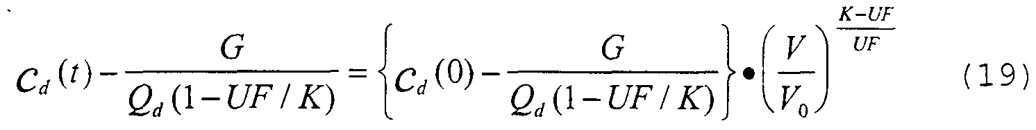
- V V 0 - UF • t (16)
- Equation (18) can be solved:
- m 0 is made only over the time period where it is found that K or K/V, respectively, are constant, i.e. where the measured data- fit equations (15) or (20) well enough.
- c d is very irregular due to inter alia bypass periods, cell-to-cell checks in the urea monitor, noise and changes in the treatment efficiency (K/V) for various reasons.
- the Hough transform (US 3069654), used for finding lines in images, is a method capable of handling such types of disturbances.
- the Hough transform looks for straight lines that passes through the largest number of points. So even if a large number of points are outside the line, this method can still work. It will also find several lines, if there are changes in the treatment efficiency.
- the urea generation rate G is estimated from patient data, for example removed amount of urea during a week.
- a continuous measurement is performed in the effluent dialysate of urea concentration c d .
- the urea concentration c d times the dialysate flow rate Q d is integrated tc provide the total removed urea U.
- the measurement is started at time zero, which is defined as the time where the measurement of urea concentration exceeds a certain level during more than five minutes.
- the urea concentration c d is plotted versus time and the total removed urea U is calculated by integrating the urea concentration c d times Q Q .
- the data of the urea concentration curve is processed by subtracting the offset term G/Q d from the urea concentration c d and plotting the logaritnm of the corrected urea concentration. Then, the curve is processed for finding a portion where K/V is substantially constant, as discussed above in connection with equation (15). This is performed by using the Hough transform of finding a line which passes through the largest number of points on the logarithm of the corrected urea concentration curve. When a portion of sufficient length has been located, the slope of tne curve is determined for calculating K/V.
- a number of measurement values of the urea concentration c d is selected which are within a certain deviation from the line obtained by the Hough transform, for example within 1% from the line.
- the instantaneous mass of urea is calculated by using equation (9 .
- these instantaneous mass values are referenced to time zero, as defined above, by using equation (10) for obtaining several calculated values of m 0 .
- the median value of these calculated initial mass values are regarded as the best estimate of the initial mass mo of the body.
- the dose of the treatment can be calculated by using equation (11) to obtain K/V at each moment of time. Then, K/V is integrated over the time to obtain Kt/V. When the desired ⁇ ose has been obtained, the dialysis treatment is terminated.
- the initial urea blood concentration c b pre m tne body can be obtained without the need for taking any blood sample by dividing the estimated mass m 0 with the distribution volume V 0 . Since the total removed urea U is calculated continuously, the urea mass after the dialysis treatment is known and the post urea blood concentration c b post can oe estimated since ultrafiltration is also known. The post urea concentration is the equilibrated urea concentration, since tne method according to the present invention calculates on total urea mass m the body.
- URR or SRI can be calculated according to equations (2) or (3) .
- equation (1) can be used for estimating the dialysis dose Kt/V.
- the obtained determination of the initial mass m 3 can oe used for calculating the urea distribution volume V of t ne patient, for example after completion of the dialysis session.
- the initial urea concentration in blood c b pre is measured before the dialysis to obtain a value of the mean urea concentration before dialysis, for example by a blood sample or equilibrated dialysate measurement.
- This urea concentration is equal to the "mean" urea concentration according to the present invention, since urea is initially equally distributed in the body of a patient.
- the distribution volume V pre (V 0 ) can be calculated by dividing the initial urea mass m 0 as calculated according to the present invention with measured blood concentration c b pre .
- V post i.e. the distribution volume of urea after the dialysis treatment.
- V pos - should be fairly constant for a normal patient in a steady state and can be used as an additional clinical parameter.
- K is assumed constant as discussed in relation to equations (16) to (19) .
- the line itself can be used for the calculations.
- the total removed urea U curve can be approximated with one or several exponential curves using the Hough transform.
- the dialysis treatment is interrupted regularly for self-calibration of the machine.
- valve 16 is opened while valves 14 and 15 are closed, see Fig. 1.
- the dialysis cf the blood ceases after a short while when the dialysis solution inside the dialyzer has obtained equilibrium with the blood.
- the urea concentration curves such self-calibration periods are visible by regular dips in the curve, see Fig. 5, where such self- calibration is carried out with 30 minutes intervals. After each such self-calibration, the dialysis starts again at a slightly higher level.
- the time scale should be adjusted to remove a portion C of the stop period, since there is obviously no dialysis at least during a portion of the stop period.
- the stop period is replaced by a period of 30 seconds. This is substantially independent of the actual length of the stop period, which can 5 be anything from 35 seconds to several minutes.
- the present invention can obtain a value of the initial mass of urea in the body of a patient.
- the invention can also be utilised in other areas, where it is of interest to know the mass of a substance C or composition, such as in a beer brewery.
- urea Other substances than urea can be monitored, such as creatinine, sodium, potassium, calcium, magnesium, bicarbonate, glucose, ⁇ 2 -microglobuline, etc. It is also possible to monitor the conductivity of the plasma water or blood or the osmolarity 5 thereof. It is also possible to use the principles of the invention in connection with gases, such as oxygen gas, nitrogen gas or carbon dioxide gas.
- gases such as oxygen gas, nitrogen gas or carbon dioxide gas.
- compositions in the body having some active mechanism interfering in the body such C as for sodium and potassium ions, such interaction should be taken account for.
- the dialysis dose can be calculated by using the initial and final dialysate urea concentrations c ⁇ pre and c dp0st and using the equation:
- U can be used for verifying that tne calculations using the concentration c d are correct.
- Asy m 0 + G - t - G / (K/V) ( 24 )
- the initial mass of urea is determined and several clinical parameters are calculated therefrom.
- the blood concentration of urea cannot be obtained, but needs to be measured by taking a blood sample and analysing it later, or by equilibrated ultrafiltration before the dialysis treatment is started.
- Fig. 9 is a schematic view similar to Fig. 2.
- a pump 24 connected to the inlet of the dialyser between the valve 14 and the dialyser 1.
- a bag 25 comprising a material to be added to the dialysis circuit via pump 24.
- Fig. 9 shows a pump 26 connected to the blood circuit at the inlet of the dialyser 1 for introducing a material comprised in a bag 27 connected tc the other side of the pump 26.
- any of these devices can be used for introducing a disturbance to the inlet of the dialyser. It is also possible to produce • a disturbance by operating the concentrate pumps 8 and/or 9.
- the disturbance is a change of a parameter of the dialysis fluid or the blood.
- the disturbance can be a change of the conductivity or a change of the urea concentration.
- the urea monitor can measure both urea concentration and conductivity in the effluent dialysate. If another measurement instrument is used, any other substance can be used as a disturbance, as soon as it is compatible with the body, such as sodium, bicarbonate etc.
- the influence by the dialyser on the disturbance is measured downstream of the dialyser, for example by the urea sensor.
- a portion of the disturbing material will pass the membrane from the dialysate to the blood or vice versa.
- the amount passing the membrane is dependent on the dialysance cf the membrane .
- the dialysance of the dialyser can be determined according to equation (see EP 547 025, the contence 5 of which is included in the present application by reference) :
- Indexes 1 and 2 indicates before and after the step change.
- the introduced concentration can be measured or be 5 determined by the set values of the concentration pumps.
- the disturbance can be a change of conductivity or a change of urea concentration or any other substance that can be measured and is compatible with the body.
- urea monitor measures the concentration of urea in the effluent fluid continuously.
- the urea concentration at the start of the treatment can be extrapolated from the first 5 to 20 minutes of treatment as shown in Fig. 10.
- the plasma water concentration of urea in the body at the start of the treatment can be determined according to the formula:
- K e effective clearance of the dialyser for urea Since the plamsa water concentration of urea can be calculated as indicated above and the amount of urea at the start of the treatment is estimated according to the present invention, the distribution volume V of urea in the body can be calculated. This distribution volume V is an important clinical parameter, which now can be measured with high accuracy.
- the invention has been described in connection with removing a substance from the body, such as urea. The same principle is valid for the addition of a substance to the body, such as bicarbonate, acetate or lactate, etc.
- the invention has been described in connection with a urea monitor, which measures the urea concentration in the dialysate continuously.
- the invention can also be used for peritoneal dialysis, where the effluent dialysate is monitored for a certain substance or composition. Specially at tidal automatic peritoneal dialysis, where the dialysate in the patient is partially replaced periodically, the principles of this invention could be applied.
Abstract
Description


Claims
Priority Applications (7)
| Application Number | Priority Date | Filing Date | Title |
|---|---|---|---|
| CA002292717A CA2292717C (en) | 1997-06-02 | 1998-06-02 | Method and device for calculating dialysis efficiency |
| DE69834034T DE69834034T2 (en) | 1997-06-02 | 1998-06-02 | DEVICE FOR CALCULATING DIALYSIS EFFICIENCY |
| EP98928741A EP0986410B1 (en) | 1997-06-02 | 1998-06-02 | Device for calculating dialysis efficiency |
| JP50225899A JP4148536B2 (en) | 1997-06-02 | 1998-06-02 | Device for calculating the efficiency of dialysis |
| US09/424,900 US6258027B1 (en) | 1997-06-02 | 1998-06-02 | Method and device for calculating dialysis efficiency |
| BR9809718-0A BR9809718A (en) | 1997-06-02 | 1998-06-02 | Process and apparatus for calculating the mass of a composition in a fluid volume |
| AU80466/98A AU732784B2 (en) | 1997-06-02 | 1998-06-02 | Method and device for calculating dialysis efficiency |
Applications Claiming Priority (4)
| Application Number | Priority Date | Filing Date | Title |
|---|---|---|---|
| SE9702074-7 | 1997-06-02 | ||
| SE9702074A SE9702074D0 (en) | 1997-06-02 | 1997-06-02 | Method and device for calculating dialysis efficiency |
| FR9715818A FR2771931B1 (en) | 1997-12-09 | 1997-12-09 | METHOD FOR DETERMINING A SIGNIFICANT PARAMETER OF THE PROGRESS OF AN EXTRACORPOREAL BLOOD TREATMENT |
| FR97/15818 | 1997-12-09 |
Publications (1)
| Publication Number | Publication Date |
|---|---|
| WO1998055166A1 true WO1998055166A1 (en) | 1998-12-10 |
Family
ID=26233989
Family Applications (1)
| Application Number | Title | Priority Date | Filing Date |
|---|---|---|---|
| PCT/SE1998/001048 WO1998055166A1 (en) | 1997-06-02 | 1998-06-02 | Method and device for calculating dialysis efficiency |
Country Status (13)
| Country | Link |
|---|---|
| US (1) | US6258027B1 (en) |
| EP (1) | EP0986410B1 (en) |
| JP (1) | JP4148536B2 (en) |
| KR (1) | KR100518185B1 (en) |
| AT (1) | ATE321580T1 (en) |
| AU (1) | AU732784B2 (en) |
| BR (1) | BR9809718A (en) |
| CA (1) | CA2292717C (en) |
| DE (1) | DE69834034T2 (en) |
| ES (1) | ES2260838T3 (en) |
| SE (1) | SE9702074D0 (en) |
| TW (1) | TW394692B (en) |
| WO (1) | WO1998055166A1 (en) |
Cited By (17)
| Publication number | Priority date | Publication date | Assignee | Title |
|---|---|---|---|---|
| WO2000038761A2 (en) | 1998-12-24 | 2000-07-06 | Fresenius Medical Care Deutschland Gmbh | Method for determining the volume of distribution of a blood component during a blood treatment, and device |
| JP2001029456A (en) * | 1999-06-22 | 2001-02-06 | Fresenius Medical Care Deutschland Gmbh | Method for determining efficiency of dialyzer of dialyzing apparatus and dialyzing apparatus for effecting the same |
| EP1029554A3 (en) * | 1999-02-19 | 2001-06-06 | Fresenius Medical Care Deutschland GmbH | Apparatus for dialysis treatment |
| EP1396274A1 (en) * | 2002-09-05 | 2004-03-10 | Gambro Lundia AB | Controller and control method for a blood treatment equipment |
| US7435235B2 (en) * | 2004-05-07 | 2008-10-14 | Gambro Lundia Ab | Blood treatment equipment, method, and software program for controlling infusion in blood treatment equipment |
| WO2009013575A1 (en) * | 2007-06-20 | 2009-01-29 | B. Braun Avitum Ag | Method for determining the reduction ratio or the kt/v value of a kidney substitution treatment and apparatus for the realisation of the method |
| US7488447B2 (en) * | 2002-10-30 | 2009-02-10 | Gambro Lundia Ab | Method and an apparatus for determining the efficiency of dialysis |
| EP2000160A3 (en) * | 2002-10-30 | 2009-03-11 | Gambro Lundia AB | Method and apparatuses for determining the efficiency of dialysis |
| EP2163271A1 (en) * | 2008-09-15 | 2010-03-17 | B. Braun Avitum AG | Method to determine the Kt/V parameter in kidney substitution treatments based on a non-linear fitting procedure |
| EP2198900A2 (en) | 1998-10-23 | 2010-06-23 | Gambro Ab | Method and device for detecting access recirculation |
| US7896831B2 (en) | 1998-10-23 | 2011-03-01 | Gambro Lundia Ab | Method and apparatus for calculating fluid flow rate |
| EP2292283A1 (en) * | 2009-09-04 | 2011-03-09 | B. Braun Avitum AG | Method and device to obtain physiological parameters and detect clinical or subclinical abnormalities during a kidney substitution treatment |
| CN103228301A (en) * | 2010-08-17 | 2013-07-31 | 贝朗爱敦股份公司 | Apparatus for extracorporeal blood treatment |
| EP2926845A1 (en) * | 2014-04-03 | 2015-10-07 | B. Braun Avitum AG | Device and method for determining a volume of distribution for a dialysis patient |
| WO2018095694A1 (en) * | 2016-11-25 | 2018-05-31 | Gambro Lundia Ab | Apparatus for extracorporeal blood treatment |
| US11376354B2 (en) | 2016-11-25 | 2022-07-05 | Gambro Lundia Ab | Apparatus for extracorporeal blood treatment |
| US11383012B2 (en) | 2016-11-25 | 2022-07-12 | Gambro Lundia Ab | Apparatus for extracorporeal blood treatment |
Families Citing this family (28)
| Publication number | Priority date | Publication date | Assignee | Title |
|---|---|---|---|---|
| US6212424B1 (en) * | 1998-10-29 | 2001-04-03 | Rio Grande Medical Technologies, Inc. | Apparatus and method for determination of the adequacy of dialysis by non-invasive near-infrared spectroscopy |
| SE513034C2 (en) | 1997-06-02 | 2000-06-19 | Gambro Lundia Ab | Calculation of dialysis efficiency, especially by monitoring urea concentration |
| US6617488B1 (en) * | 1997-10-14 | 2003-09-09 | Indicator Technologies, Inc. | Method and apparatus for indicating the conditions in an absorbent article |
| JP4451544B2 (en) * | 2000-06-06 | 2010-04-14 | 平田機工株式会社 | Door opening and closing device |
| US6610027B1 (en) * | 2000-08-17 | 2003-08-26 | Mohamed Kaled Mohamed El Hatu | Hemodialysis |
| US7326576B2 (en) * | 2003-04-09 | 2008-02-05 | Prescient Medical, Inc. | Raman spectroscopic monitoring of hemodialysis |
| ES2427513T3 (en) * | 2003-12-18 | 2013-10-30 | Gambro Lundia Ab | Apparatus for determining a patient parameter or treatment or device during an extracorporeal blood treatment |
| US7688440B2 (en) | 2005-01-27 | 2010-03-30 | Prescient Medical, Inc. | Raman spectroscopic test strip systems |
| US7524671B2 (en) * | 2005-01-27 | 2009-04-28 | Prescient Medical, Inc. | Handheld raman blood analyzer |
| US7651851B2 (en) * | 2005-01-27 | 2010-01-26 | Prescient Medical, Inc. | Handheld Raman body fluid analyzer |
| US7815809B2 (en) * | 2005-12-13 | 2010-10-19 | Gambro Lundia Ab | Method for conductivity calculation in a treatment fluid upstream and downstream a filtration unit in apparatuses for the blood treatment |
| KR100773549B1 (en) * | 2006-04-03 | 2007-11-07 | 삼성전자주식회사 | Method of detecting bio-molecules using the same field effect transistor |
| DE102006032926A1 (en) * | 2006-07-15 | 2008-01-17 | Fresenius Medical Care Deutschland Gmbh | Method and device for prescribing treatment parameters for extracorporeal dialysis treatments |
| US9101716B2 (en) | 2008-02-01 | 2015-08-11 | Baxter International Inc. | Multi-pass dialysis |
| CN102076368B (en) | 2008-06-26 | 2014-09-03 | 甘布罗伦迪亚股份公司 | Method and device for processing a time-dependent measurement signal |
| DE102009018649A1 (en) * | 2009-04-23 | 2010-10-28 | Fresenius Medical Care Deutschland Gmbh | Dialysis machine, method and apparatus for a dialysis machine |
| DE102009040104A1 (en) * | 2009-09-04 | 2011-03-10 | B. Braun Avitum Ag | Device for extracorporeal blood treatment |
| US8945936B2 (en) * | 2011-04-06 | 2015-02-03 | Fresenius Medical Care Holdings, Inc. | Measuring chemical properties of a sample fluid in dialysis systems |
| DE102012109858A1 (en) | 2012-10-16 | 2014-04-17 | B. Braun Avitum Ag | Dialysis optimization methods |
| DE102013104501A1 (en) * | 2013-05-02 | 2014-11-06 | B. Braun Avitum Ag | Device for extracorporeal blood treatment |
| JP5641459B1 (en) * | 2013-09-10 | 2014-12-17 | 学校法人加計学園 | A device that determines the initial dissolved mass in the body fluid of a patient from dialysis drainage |
| DE102014012423A1 (en) | 2014-08-20 | 2016-02-25 | Fresenius Medical Care Deutschland Gmbh | Dialysis machine with the ability to determine a predialytic property in the blood of a dialysis patient |
| EP3238756B1 (en) * | 2016-04-26 | 2019-09-04 | Gambro Lundia AB | Apparatus for determining a parameter indicative of the progress of an extracorporeal blood treatment |
| ES2939648T3 (en) * | 2016-12-22 | 2023-04-25 | Gambro Lundia Ab | Apparatus for the treatment of extracorporeal blood |
| WO2018114276A1 (en) * | 2016-12-22 | 2018-06-28 | Gambro Lundia Ab | Apparatus for extracorporeal blood treatment |
| CN106693096A (en) * | 2016-12-30 | 2017-05-24 | 北京迈淩医疗技术发展有限公司 | Hemodialysis device and method capable of online measuring urea clearance index |
| JP6997582B2 (en) * | 2017-10-17 | 2022-01-17 | 日機装株式会社 | Blood purification device |
| CN109147884B (en) * | 2018-09-10 | 2021-04-02 | 北京英福美信息科技股份有限公司 | Sufficiency evaluation method and system |
Citations (5)
| Publication number | Priority date | Publication date | Assignee | Title |
|---|---|---|---|---|
| US4324663A (en) * | 1976-07-30 | 1982-04-13 | Institut National De La Sante Et De La Recherche Medicale | Method and apparatus for regulating haemodialysis conditions |
| EP0547025A1 (en) * | 1988-03-03 | 1993-06-16 | Gambro Ab | Method for determining a concentration of a substance in blood or the dialysance of a dialyser |
| WO1994008641A1 (en) * | 1992-10-13 | 1994-04-28 | Baxter International Inc. | Hemodialysis monitoring system for hemodialysis machines |
| CA2178430A1 (en) * | 1995-06-07 | 1996-12-08 | James M. Brugger | Differential Conductivity Hemodynamic Monitor |
| US5598841A (en) * | 1993-09-24 | 1997-02-04 | Kowa Company Ltd. | Blood flow measurement system |
Family Cites Families (2)
| Publication number | Priority date | Publication date | Assignee | Title |
|---|---|---|---|---|
| US5644240A (en) | 1992-09-30 | 1997-07-01 | Cobe Laboratories, Inc. | Differential conductivity hemodynamic monitor |
| FR2771931B1 (en) | 1997-12-09 | 2000-01-07 | Hospal Ind | METHOD FOR DETERMINING A SIGNIFICANT PARAMETER OF THE PROGRESS OF AN EXTRACORPOREAL BLOOD TREATMENT |
-
1997
- 1997-06-02 SE SE9702074A patent/SE9702074D0/en unknown
-
1998
- 1998-06-02 JP JP50225899A patent/JP4148536B2/en not_active Expired - Fee Related
- 1998-06-02 ES ES98928741T patent/ES2260838T3/en not_active Expired - Lifetime
- 1998-06-02 EP EP98928741A patent/EP0986410B1/en not_active Expired - Lifetime
- 1998-06-02 WO PCT/SE1998/001048 patent/WO1998055166A1/en active IP Right Grant
- 1998-06-02 CA CA002292717A patent/CA2292717C/en not_active Expired - Fee Related
- 1998-06-02 KR KR10-1999-7011245A patent/KR100518185B1/en not_active IP Right Cessation
- 1998-06-02 US US09/424,900 patent/US6258027B1/en not_active Expired - Lifetime
- 1998-06-02 AU AU80466/98A patent/AU732784B2/en not_active Ceased
- 1998-06-02 BR BR9809718-0A patent/BR9809718A/en not_active IP Right Cessation
- 1998-06-02 DE DE69834034T patent/DE69834034T2/en not_active Expired - Lifetime
- 1998-06-02 AT AT98928741T patent/ATE321580T1/en not_active IP Right Cessation
- 1998-06-19 TW TW087109861A patent/TW394692B/en active
Patent Citations (5)
| Publication number | Priority date | Publication date | Assignee | Title |
|---|---|---|---|---|
| US4324663A (en) * | 1976-07-30 | 1982-04-13 | Institut National De La Sante Et De La Recherche Medicale | Method and apparatus for regulating haemodialysis conditions |
| EP0547025A1 (en) * | 1988-03-03 | 1993-06-16 | Gambro Ab | Method for determining a concentration of a substance in blood or the dialysance of a dialyser |
| WO1994008641A1 (en) * | 1992-10-13 | 1994-04-28 | Baxter International Inc. | Hemodialysis monitoring system for hemodialysis machines |
| US5598841A (en) * | 1993-09-24 | 1997-02-04 | Kowa Company Ltd. | Blood flow measurement system |
| CA2178430A1 (en) * | 1995-06-07 | 1996-12-08 | James M. Brugger | Differential Conductivity Hemodynamic Monitor |
Cited By (39)
| Publication number | Priority date | Publication date | Assignee | Title |
|---|---|---|---|---|
| EP2198900A2 (en) | 1998-10-23 | 2010-06-23 | Gambro Ab | Method and device for detecting access recirculation |
| US7955291B2 (en) | 1998-10-23 | 2011-06-07 | Gambro Lundia Ab | Method and apparatus for detecting access recirculation |
| US7896831B2 (en) | 1998-10-23 | 2011-03-01 | Gambro Lundia Ab | Method and apparatus for calculating fluid flow rate |
| WO2000038761A3 (en) * | 1998-12-24 | 2001-10-11 | Fresenius Medical Care De Gmbh | Method for determining the volume of distribution of a blood component during a blood treatment, and device |
| JP2002533170A (en) * | 1998-12-24 | 2002-10-08 | フレセニウス・メディカル・ケア・ドイッチュラント・ゲゼルシャフト・ミット・ベシュレンクテル・ハフツング | Method for estimating the distribution of blood components during extracorporeal blood processing and apparatus for implementing this method |
| US7077819B1 (en) | 1998-12-24 | 2006-07-18 | Fresenius Medical Care Deutschland Gmbh | Method for determining the distribution volume of a blood component during an extracorporeal blood treatment and device for carrying out the method |
| WO2000038761A2 (en) | 1998-12-24 | 2000-07-06 | Fresenius Medical Care Deutschland Gmbh | Method for determining the volume of distribution of a blood component during a blood treatment, and device |
| EP1029554A3 (en) * | 1999-02-19 | 2001-06-06 | Fresenius Medical Care Deutschland GmbH | Apparatus for dialysis treatment |
| JP2001029456A (en) * | 1999-06-22 | 2001-02-06 | Fresenius Medical Care Deutschland Gmbh | Method for determining efficiency of dialyzer of dialyzing apparatus and dialyzing apparatus for effecting the same |
| JP4705225B2 (en) * | 1999-06-22 | 2011-06-22 | フレセニウス・メディカル・ケア・ドイッチュラント・ゲゼルシャフト・ミット・ベシュレンクテル・ハフツング | Method for determining the efficiency of a dialyzer of a dialysis machine and a dialysis machine for carrying out this method |
| WO2004022135A1 (en) * | 2002-09-05 | 2004-03-18 | Gambro Lundia Ab | Sontrol apparatus and control method for a blood treatment equipment |
| AU2003255975B2 (en) * | 2002-09-05 | 2008-12-11 | Gambro Lundia Ab | Control apparatus and control method for a blood treatment equipment |
| EP2243502A3 (en) * | 2002-09-05 | 2012-06-13 | Gambro Lundia AB | Control apparatus and control method for a blood treatment equipment |
| AU2003255975B9 (en) * | 2002-09-05 | 2009-06-11 | Gambro Lundia Ab | Control apparatus and control method for a blood treatment equipment |
| CN100531810C (en) * | 2002-09-05 | 2009-08-26 | 甘布罗伦迪亚股份公司 | Control apparatus and control method for a blood treatment equipment |
| US8741147B2 (en) | 2002-09-05 | 2014-06-03 | Gambro Lundia Ab | Control apparatus and control method for a blood treatment equipment |
| DE10393156C5 (en) * | 2002-09-05 | 2014-08-14 | Gambro Lundia Ab | Control device and control method for a blood treatment device |
| EP1396274A1 (en) * | 2002-09-05 | 2004-03-10 | Gambro Lundia AB | Controller and control method for a blood treatment equipment |
| CN101596333B (en) * | 2002-09-05 | 2012-11-21 | 甘布罗伦迪亚股份公司 | Control apparatus and control method for a blood treatment equipment |
| US8512564B2 (en) | 2002-09-05 | 2013-08-20 | Gambro Lundia Ab | Control apparatus and control method for a blood treatment equipment |
| US7488447B2 (en) * | 2002-10-30 | 2009-02-10 | Gambro Lundia Ab | Method and an apparatus for determining the efficiency of dialysis |
| EP2000160A3 (en) * | 2002-10-30 | 2009-03-11 | Gambro Lundia AB | Method and apparatuses for determining the efficiency of dialysis |
| CN1946441B (en) * | 2004-05-07 | 2011-04-13 | 甘布罗伦迪亚股份公司 | Blood treatment equipment, method for controlling infusion |
| US7435235B2 (en) * | 2004-05-07 | 2008-10-14 | Gambro Lundia Ab | Blood treatment equipment, method, and software program for controlling infusion in blood treatment equipment |
| US8702979B2 (en) | 2007-06-20 | 2014-04-22 | B. Braun Avitum Ag | Method for determining the reduction ratio or the Kt/V value of a kidney substitution treatment and apparatus for the realisation of the method |
| WO2009013575A1 (en) * | 2007-06-20 | 2009-01-29 | B. Braun Avitum Ag | Method for determining the reduction ratio or the kt/v value of a kidney substitution treatment and apparatus for the realisation of the method |
| EP2163271A1 (en) * | 2008-09-15 | 2010-03-17 | B. Braun Avitum AG | Method to determine the Kt/V parameter in kidney substitution treatments based on a non-linear fitting procedure |
| WO2011026645A1 (en) * | 2009-09-04 | 2011-03-10 | B. Braun Avitum Ag | Method and device to obtain physiological parameters and detect clinical or subclinical abnormalities during a kidney substitution treatment |
| EP2292283A1 (en) * | 2009-09-04 | 2011-03-09 | B. Braun Avitum AG | Method and device to obtain physiological parameters and detect clinical or subclinical abnormalities during a kidney substitution treatment |
| CN103228301A (en) * | 2010-08-17 | 2013-07-31 | 贝朗爱敦股份公司 | Apparatus for extracorporeal blood treatment |
| US9220827B2 (en) | 2010-08-17 | 2015-12-29 | B. Braun Avitum Ag | Apparatus for extracorporeal blood treatment |
| CN104970767A (en) * | 2014-04-03 | 2015-10-14 | B·布莱恩·阿维图姆股份公司 | Apparatus And Method For Determining Distribution Volume In Dialysis Patient |
| EP2926845A1 (en) * | 2014-04-03 | 2015-10-07 | B. Braun Avitum AG | Device and method for determining a volume of distribution for a dialysis patient |
| US10101316B2 (en) | 2014-04-03 | 2018-10-16 | B. Braun Avitum Ag | Apparatus and method for determining distribution volume in dialysis patient |
| CN104970767B (en) * | 2014-04-03 | 2020-01-17 | B·布莱恩·阿维图姆股份公司 | Device and method for determining the distribution volume of a dialysis patient |
| WO2018095694A1 (en) * | 2016-11-25 | 2018-05-31 | Gambro Lundia Ab | Apparatus for extracorporeal blood treatment |
| US11376354B2 (en) | 2016-11-25 | 2022-07-05 | Gambro Lundia Ab | Apparatus for extracorporeal blood treatment |
| US11383012B2 (en) | 2016-11-25 | 2022-07-12 | Gambro Lundia Ab | Apparatus for extracorporeal blood treatment |
| US11426501B2 (en) | 2016-11-25 | 2022-08-30 | Gambro Lundia Ab | Apparatus for extracorporeal blood treatment |
Also Published As
| Publication number | Publication date |
|---|---|
| JP4148536B2 (en) | 2008-09-10 |
| DE69834034D1 (en) | 2006-05-18 |
| CA2292717A1 (en) | 1998-12-10 |
| TW394692B (en) | 2000-06-21 |
| JP2002514120A (en) | 2002-05-14 |
| AU732784B2 (en) | 2001-04-26 |
| EP0986410A1 (en) | 2000-03-22 |
| BR9809718A (en) | 2000-07-11 |
| EP0986410B1 (en) | 2006-03-29 |
| ES2260838T3 (en) | 2006-11-01 |
| SE9702074D0 (en) | 1997-06-02 |
| DE69834034T2 (en) | 2006-08-17 |
| US6258027B1 (en) | 2001-07-10 |
| KR100518185B1 (en) | 2005-10-04 |
| CA2292717C (en) | 2006-11-14 |
| ATE321580T1 (en) | 2006-04-15 |
| KR20010013254A (en) | 2001-02-26 |
| AU8046698A (en) | 1998-12-21 |
Similar Documents
| Publication | Publication Date | Title |
|---|---|---|
| EP0986410B1 (en) | Device for calculating dialysis efficiency | |
| EP1037681B1 (en) | Device for calculating dialysis efficiency | |
| EP1396274B1 (en) | Controller for a blood treatment equipment | |
| JP4509387B2 (en) | Method for calculating the distribution of blood components during extracorporeal blood treatment and apparatus for carrying out this method | |
| JP5080570B2 (en) | Device and method for controlling an extracorporeal blood treatment device | |
| JP3547436B2 (en) | Hemodialysis monitoring system for hemodialysis equipment | |
| JP2532261B2 (en) | Equipment for hemodialysis treatment | |
| US6187199B1 (en) | Process and device for determining hemodialysis parameters | |
| US5507723A (en) | Method and system for optimizing dialysis clearance | |
| US6217539B1 (en) | Method of in-vivo determination of hemodialysis parameters and a device for carrying out the method | |
| Bankhead et al. | Accuracy of urea removal estimated by kinetic models | |
| KR19990029075A (en) | Hemodialysis monitor system for hemodialysis | |
| JP4219094B2 (en) | Method for determining dialysance and apparatus for the method | |
| JP4676612B2 (en) | Method for measuring parameters indicating progress of extracorporeal blood treatment | |
| Garred et al. | Urea rebound and delivered Kt/V determination with a continuous urea sensor. | |
| EP3238756B1 (en) | Apparatus for determining a parameter indicative of the progress of an extracorporeal blood treatment | |
| US20230173154A1 (en) | Dialysis apparatus having an apparatus for determining at least two hemodialysis parameters |
Legal Events
| Date | Code | Title | Description |
|---|---|---|---|
| AK | Designated states |
Kind code of ref document: A1 Designated state(s): AL AM AT AU AZ BA BB BG BR BY CA CH CN CU CZ DE DK EE ES FI GB GE GH GM GW HU ID IL IS JP KE KG KP KR KZ LC LK LR LS LT LU LV MD MG MK MN MW MX NO NZ PL PT RO RU SD SE SG SI SK SL TJ TM TR TT UA UG US UZ VN YU ZW |
|
| AL | Designated countries for regional patents |
Kind code of ref document: A1 Designated state(s): GH GM KE LS MW SD SZ UG ZW AM AZ BY KG KZ MD RU TJ TM AT BE CH CY DE DK ES FI FR GB GR IE IT LU MC NL PT SE BF BJ CF CG CI CM GA GN ML MR NE SN TD TG |
|
| DFPE | Request for preliminary examination filed prior to expiration of 19th month from priority date (pct application filed before 20040101) | ||
| 121 | Ep: the epo has been informed by wipo that ep was designated in this application | ||
| WWE | Wipo information: entry into national phase |
Ref document number: 1998928741 Country of ref document: EP |
|
| WWE | Wipo information: entry into national phase |
Ref document number: 09424900 Country of ref document: US |
|
| ENP | Entry into the national phase |
Ref document number: 2292717 Country of ref document: CA Ref country code: CA Ref document number: 2292717 Kind code of ref document: A Format of ref document f/p: F |
|
| WWE | Wipo information: entry into national phase |
Ref document number: 80466/98 Country of ref document: AU Ref document number: 1019997011245 Country of ref document: KR |
|
| WWP | Wipo information: published in national office |
Ref document number: 1998928741 Country of ref document: EP |
|
| REG | Reference to national code |
Ref country code: DE Ref legal event code: 8642 |
|
| WWP | Wipo information: published in national office |
Ref document number: 1019997011245 Country of ref document: KR |
|
| WWG | Wipo information: grant in national office |
Ref document number: 80466/98 Country of ref document: AU |
|
| WWG | Wipo information: grant in national office |
Ref document number: 1019997011245 Country of ref document: KR |
|
| WWG | Wipo information: grant in national office |
Ref document number: 1998928741 Country of ref document: EP |