WO1999007466A1 - Multiple stream high pressure mixer/reactor - Google Patents
Multiple stream high pressure mixer/reactor Download PDFInfo
- Publication number
- WO1999007466A1 WO1999007466A1 PCT/US1998/016180 US9816180W WO9907466A1 WO 1999007466 A1 WO1999007466 A1 WO 1999007466A1 US 9816180 W US9816180 W US 9816180W WO 9907466 A1 WO9907466 A1 WO 9907466A1
- Authority
- WO
- WIPO (PCT)
- Prior art keywords
- liquid
- pressure
- reaction chamber
- stream
- flow
- Prior art date
Links
Classifications
-
- B—PERFORMING OPERATIONS; TRANSPORTING
- B01—PHYSICAL OR CHEMICAL PROCESSES OR APPARATUS IN GENERAL
- B01J—CHEMICAL OR PHYSICAL PROCESSES, e.g. CATALYSIS OR COLLOID CHEMISTRY; THEIR RELEVANT APPARATUS
- B01J19/00—Chemical, physical or physico-chemical processes in general; Their relevant apparatus
- B01J19/26—Nozzle-type reactors, i.e. the distribution of the initial reactants within the reactor is effected by their introduction or injection through nozzles
-
- B—PERFORMING OPERATIONS; TRANSPORTING
- B01—PHYSICAL OR CHEMICAL PROCESSES OR APPARATUS IN GENERAL
- B01F—MIXING, e.g. DISSOLVING, EMULSIFYING OR DISPERSING
- B01F25/00—Flow mixers; Mixers for falling materials, e.g. solid particles
- B01F25/20—Jet mixers, i.e. mixers using high-speed fluid streams
- B01F25/23—Mixing by intersecting jets
-
- B—PERFORMING OPERATIONS; TRANSPORTING
- B01—PHYSICAL OR CHEMICAL PROCESSES OR APPARATUS IN GENERAL
- B01J—CHEMICAL OR PHYSICAL PROCESSES, e.g. CATALYSIS OR COLLOID CHEMISTRY; THEIR RELEVANT APPARATUS
- B01J14/00—Chemical processes in general for reacting liquids with liquids; Apparatus specially adapted therefor
-
- B—PERFORMING OPERATIONS; TRANSPORTING
- B01—PHYSICAL OR CHEMICAL PROCESSES OR APPARATUS IN GENERAL
- B01J—CHEMICAL OR PHYSICAL PROCESSES, e.g. CATALYSIS OR COLLOID CHEMISTRY; THEIR RELEVANT APPARATUS
- B01J19/00—Chemical, physical or physico-chemical processes in general; Their relevant apparatus
- B01J19/0093—Microreactors, e.g. miniaturised or microfabricated reactors
-
- B—PERFORMING OPERATIONS; TRANSPORTING
- B01—PHYSICAL OR CHEMICAL PROCESSES OR APPARATUS IN GENERAL
- B01J—CHEMICAL OR PHYSICAL PROCESSES, e.g. CATALYSIS OR COLLOID CHEMISTRY; THEIR RELEVANT APPARATUS
- B01J23/00—Catalysts comprising metals or metal oxides or hydroxides, not provided for in group B01J21/00
- B01J23/70—Catalysts comprising metals or metal oxides or hydroxides, not provided for in group B01J21/00 of the iron group metals or copper
- B01J23/76—Catalysts comprising metals or metal oxides or hydroxides, not provided for in group B01J21/00 of the iron group metals or copper combined with metals, oxides or hydroxides provided for in groups B01J23/02 - B01J23/36
- B01J23/80—Catalysts comprising metals or metal oxides or hydroxides, not provided for in group B01J21/00 of the iron group metals or copper combined with metals, oxides or hydroxides provided for in groups B01J23/02 - B01J23/36 with zinc, cadmium or mercury
-
- B—PERFORMING OPERATIONS; TRANSPORTING
- B01—PHYSICAL OR CHEMICAL PROCESSES OR APPARATUS IN GENERAL
- B01J—CHEMICAL OR PHYSICAL PROCESSES, e.g. CATALYSIS OR COLLOID CHEMISTRY; THEIR RELEVANT APPARATUS
- B01J3/00—Processes of utilising sub-atmospheric or super-atmospheric pressure to effect chemical or physical change of matter; Apparatus therefor
-
- B—PERFORMING OPERATIONS; TRANSPORTING
- B01—PHYSICAL OR CHEMICAL PROCESSES OR APPARATUS IN GENERAL
- B01J—CHEMICAL OR PHYSICAL PROCESSES, e.g. CATALYSIS OR COLLOID CHEMISTRY; THEIR RELEVANT APPARATUS
- B01J4/00—Feed or outlet devices; Feed or outlet control devices
- B01J4/02—Feed or outlet devices; Feed or outlet control devices for feeding measured, i.e. prescribed quantities of reagents
-
- C—CHEMISTRY; METALLURGY
- C01—INORGANIC CHEMISTRY
- C01B—NON-METALLIC ELEMENTS; COMPOUNDS THEREOF; METALLOIDS OR COMPOUNDS THEREOF NOT COVERED BY SUBCLASS C01C
- C01B13/00—Oxygen; Ozone; Oxides or hydroxides in general
- C01B13/14—Methods for preparing oxides or hydroxides in general
- C01B13/36—Methods for preparing oxides or hydroxides in general by precipitation reactions in aqueous solutions
- C01B13/363—Mixtures of oxides or hydroxides by precipitation
-
- C—CHEMISTRY; METALLURGY
- C01—INORGANIC CHEMISTRY
- C01B—NON-METALLIC ELEMENTS; COMPOUNDS THEREOF; METALLOIDS OR COMPOUNDS THEREOF NOT COVERED BY SUBCLASS C01C
- C01B33/00—Silicon; Compounds thereof
- C01B33/20—Silicates
- C01B33/26—Aluminium-containing silicates, i.e. silico-aluminates
-
- C—CHEMISTRY; METALLURGY
- C01—INORGANIC CHEMISTRY
- C01F—COMPOUNDS OF THE METALS BERYLLIUM, MAGNESIUM, ALUMINIUM, CALCIUM, STRONTIUM, BARIUM, RADIUM, THORIUM, OR OF THE RARE-EARTH METALS
- C01F11/00—Compounds of calcium, strontium, or barium
- C01F11/18—Carbonates
- C01F11/181—Preparation of calcium carbonate by carbonation of aqueous solutions and characterised by control of the carbonation conditions
-
- C—CHEMISTRY; METALLURGY
- C01—INORGANIC CHEMISTRY
- C01F—COMPOUNDS OF THE METALS BERYLLIUM, MAGNESIUM, ALUMINIUM, CALCIUM, STRONTIUM, BARIUM, RADIUM, THORIUM, OR OF THE RARE-EARTH METALS
- C01F11/00—Compounds of calcium, strontium, or barium
- C01F11/46—Sulfates
- C01F11/462—Sulfates of Sr or Ba
-
- C—CHEMISTRY; METALLURGY
- C01—INORGANIC CHEMISTRY
- C01G—COMPOUNDS CONTAINING METALS NOT COVERED BY SUBCLASSES C01D OR C01F
- C01G1/00—Methods of preparing compounds of metals not covered by subclasses C01B, C01C, C01D, or C01F, in general
- C01G1/02—Oxides
-
- C—CHEMISTRY; METALLURGY
- C01—INORGANIC CHEMISTRY
- C01G—COMPOUNDS CONTAINING METALS NOT COVERED BY SUBCLASSES C01D OR C01F
- C01G9/00—Compounds of zinc
- C01G9/006—Compounds containing, besides zinc, two ore more other elements, with the exception of oxygen or hydrogen
-
- B—PERFORMING OPERATIONS; TRANSPORTING
- B01—PHYSICAL OR CHEMICAL PROCESSES OR APPARATUS IN GENERAL
- B01F—MIXING, e.g. DISSOLVING, EMULSIFYING OR DISPERSING
- B01F23/00—Mixing according to the phases to be mixed, e.g. dispersing or emulsifying
- B01F23/40—Mixing liquids with liquids; Emulsifying
-
- B—PERFORMING OPERATIONS; TRANSPORTING
- B01—PHYSICAL OR CHEMICAL PROCESSES OR APPARATUS IN GENERAL
- B01F—MIXING, e.g. DISSOLVING, EMULSIFYING OR DISPERSING
- B01F33/00—Other mixers; Mixing plants; Combinations of mixers
- B01F33/30—Micromixers
-
- B—PERFORMING OPERATIONS; TRANSPORTING
- B01—PHYSICAL OR CHEMICAL PROCESSES OR APPARATUS IN GENERAL
- B01J—CHEMICAL OR PHYSICAL PROCESSES, e.g. CATALYSIS OR COLLOID CHEMISTRY; THEIR RELEVANT APPARATUS
- B01J2208/00—Processes carried out in the presence of solid particles; Reactors therefor
- B01J2208/00008—Controlling the process
- B01J2208/00654—Controlling the process by measures relating to the particulate material
- B01J2208/00672—Particle size selection
-
- B—PERFORMING OPERATIONS; TRANSPORTING
- B01—PHYSICAL OR CHEMICAL PROCESSES OR APPARATUS IN GENERAL
- B01J—CHEMICAL OR PHYSICAL PROCESSES, e.g. CATALYSIS OR COLLOID CHEMISTRY; THEIR RELEVANT APPARATUS
- B01J2219/00—Chemical, physical or physico-chemical processes in general; Their relevant apparatus
- B01J2219/00049—Controlling or regulating processes
- B01J2219/00162—Controlling or regulating processes controlling the pressure
-
- B—PERFORMING OPERATIONS; TRANSPORTING
- B01—PHYSICAL OR CHEMICAL PROCESSES OR APPARATUS IN GENERAL
- B01J—CHEMICAL OR PHYSICAL PROCESSES, e.g. CATALYSIS OR COLLOID CHEMISTRY; THEIR RELEVANT APPARATUS
- B01J2219/00—Chemical, physical or physico-chemical processes in general; Their relevant apparatus
- B01J2219/00049—Controlling or regulating processes
- B01J2219/00164—Controlling or regulating processes controlling the flow
-
- B—PERFORMING OPERATIONS; TRANSPORTING
- B01—PHYSICAL OR CHEMICAL PROCESSES OR APPARATUS IN GENERAL
- B01J—CHEMICAL OR PHYSICAL PROCESSES, e.g. CATALYSIS OR COLLOID CHEMISTRY; THEIR RELEVANT APPARATUS
- B01J2219/00—Chemical, physical or physico-chemical processes in general; Their relevant apparatus
- B01J2219/00781—Aspects relating to microreactors
- B01J2219/00889—Mixing
-
- B—PERFORMING OPERATIONS; TRANSPORTING
- B01—PHYSICAL OR CHEMICAL PROCESSES OR APPARATUS IN GENERAL
- B01J—CHEMICAL OR PHYSICAL PROCESSES, e.g. CATALYSIS OR COLLOID CHEMISTRY; THEIR RELEVANT APPARATUS
- B01J2219/00—Chemical, physical or physico-chemical processes in general; Their relevant apparatus
- B01J2219/00781—Aspects relating to microreactors
- B01J2219/00891—Feeding or evacuation
-
- C—CHEMISTRY; METALLURGY
- C01—INORGANIC CHEMISTRY
- C01P—INDEXING SCHEME RELATING TO STRUCTURAL AND PHYSICAL ASPECTS OF SOLID INORGANIC COMPOUNDS
- C01P2002/00—Crystal-structural characteristics
- C01P2002/20—Two-dimensional structures
- C01P2002/22—Two-dimensional structures layered hydroxide-type, e.g. of the hydrotalcite-type
-
- C—CHEMISTRY; METALLURGY
- C01—INORGANIC CHEMISTRY
- C01P—INDEXING SCHEME RELATING TO STRUCTURAL AND PHYSICAL ASPECTS OF SOLID INORGANIC COMPOUNDS
- C01P2002/00—Crystal-structural characteristics
- C01P2002/70—Crystal-structural characteristics defined by measured X-ray, neutron or electron diffraction data
- C01P2002/72—Crystal-structural characteristics defined by measured X-ray, neutron or electron diffraction data by d-values or two theta-values, e.g. as X-ray diagram
-
- C—CHEMISTRY; METALLURGY
- C01—INORGANIC CHEMISTRY
- C01P—INDEXING SCHEME RELATING TO STRUCTURAL AND PHYSICAL ASPECTS OF SOLID INORGANIC COMPOUNDS
- C01P2004/00—Particle morphology
- C01P2004/30—Particle morphology extending in three dimensions
- C01P2004/38—Particle morphology extending in three dimensions cube-like
-
- C—CHEMISTRY; METALLURGY
- C01—INORGANIC CHEMISTRY
- C01P—INDEXING SCHEME RELATING TO STRUCTURAL AND PHYSICAL ASPECTS OF SOLID INORGANIC COMPOUNDS
- C01P2004/00—Particle morphology
- C01P2004/51—Particles with a specific particle size distribution
- C01P2004/52—Particles with a specific particle size distribution highly monodisperse size distribution
-
- C—CHEMISTRY; METALLURGY
- C01—INORGANIC CHEMISTRY
- C01P—INDEXING SCHEME RELATING TO STRUCTURAL AND PHYSICAL ASPECTS OF SOLID INORGANIC COMPOUNDS
- C01P2004/00—Particle morphology
- C01P2004/60—Particles characterised by their size
- C01P2004/61—Micrometer sized, i.e. from 1-100 micrometer
-
- C—CHEMISTRY; METALLURGY
- C01—INORGANIC CHEMISTRY
- C01P—INDEXING SCHEME RELATING TO STRUCTURAL AND PHYSICAL ASPECTS OF SOLID INORGANIC COMPOUNDS
- C01P2004/00—Particle morphology
- C01P2004/60—Particles characterised by their size
- C01P2004/62—Submicrometer sized, i.e. from 0.1-1 micrometer
Definitions
- the present invention is directed to a continuous high pressure multiple discrete stream chemical mixer/reactor and its use, particularly for performing irreversible reactions, e.g. precipitation and nucleation reactions .
- less than acceptable output product compositions may result.
- compromised output products include non-uniform seed precipitation products, incompletely reacted source materials, isolation of unreacted source material by reacted product, liquid striation, and the like.
- Mixing effects are particularly significant in high reactivity or low diffusivity systems where concentration inhomogeneities cannot be leveled off before appreciable reaction occurs .
- Some reactions in low viscosity systems are fast enough, relative to conventional mixing, that conversion occurs in a region or reaction zone where partial segregation of the reactants causes steep concentration gradients which can result in a reduced reaction rate relative to perfect mixing.
- a stirred tank e.g. an autoclave
- a stirred tank reactor has several limitations, especially when used to perform fast chemical reactions .
- the flow field is inhomogen- eous and generally of low intensity and the predominant flow pattern is back-mixing, making scale-up difficult due to the complexity of the flow. This often leads to large scaling ratios, i.e. due to inefficiencies in mixing more source materials are required to obtain a desired output quantity.
- Macromixing refers to the general distribution of an additive or reactant on a coarse scale in a mixer via turbulent dispersion.
- global axial macromixing can be characterized by a residence time distribution and global radial macromixing by a coefficient of variation.
- Mesomixing refers to mixing at an intermediate scale between macromixing and micromixing. Mesomixing results in a reduction of the scale of segregation between reactants, i.e. feed eddies are reduced in size to small "engulf- ment” sized eddies.
- Micromixing refers to the final stages of mixing (engulfment in small eddies and molecular diffusion) which brings together liquid reactants on a molecular scale.
- U.S. Pat. Nos. 5,417,956 and 5,466,646 disclose methods of producing nanosize particles by use of the emulsion forming apparatus of U.S. Pat. Nos. 4,533,254 and 4,908,154.
- the process entails premixing two liquids which react with each other and then subjecting that single premixture to high pressure and a subsequent high energy mixing process, i.e. high shear, preferably using a Microfluid- izer® processor, to generate nanosize particles.
- the reaction kinetics are such that significant precipitate nucleation and reaction will have occurred during the pre-mixing, well prior to introduction of the mixture into the high energy mixing zone.
- the nuclei formed in the premixture are less uniform than when the mixing/reacting is performed with the apparatus of the present invention.
- the predominant mode of operation of the Microfluidizer® device is breaking up precipitant material to produce smaller particles, rather than direct control of the size of the precipitant material during its initial formation.
- the present invention produces nanosize product particles of a smaller, more uniform size distribution that enhances use of the products for various applications, including in the field of catalysis.
- a single hydraulically-driven intensifier is moved in an axial reciprocating stroke to pressurize and process a single stream of pumpable fluid. No matching of flows of two or more different fluid streams, nor use of separate high pressurizing pumps for each different fluid stream, nor flow control of multiple streams are required.
- Control of the flow of two or more pumpable fluid source materials, both individually and in relation to each other, at high pressure is critical to the present invention.
- low pressures up to a maximum of about 5,000 psi, as used in hydraulically- driven systems, flow control is obtainable with proportional control valves.
- control valves and materials are not available to provide the required degree of flow control for the low viscosity fluids used herein.
- gear pumps have been used to extrude high viscosity thermoplastic materials at pressures up to 30,000 psi, they are not useful with the low viscosity source material streams of the present invention.
- the multiple stream high pressure continuous chemical mixer- /reactor of this invention comprises in combination (i) means for individually pressurizing each of two or more different liquid source material streams to high pressure; (ii) means for individually monitoring the flow of each liquid source material stream; (iii) a reaction chamber for receiving the pressurized liquid source material streams at high velocity; (iv) means for discharging a product stream which results from mixing of the pressurized liquid source material streams at high pressure and high velocity in the reaction chamber; and (v) means for controlling the rate of delivery of each reactant stream to the reaction chamber at a determined continuous stoichiometric rate.
- the multiple stream high pressure mixer/reactor is controlled by a closed loop control means combining individual stream transducers to allow calculation of flow of each stream, computer hardware with control system application software, a hydraulic pressure/flow metering valve for each stream, and input/output connections to the computer hardware for the transducer data and meter valve drive.
- Each reactant stream is pressurized by a hydraulically-driven intensifier.
- a hydraulic pump pressures a hydraulic fluid which drives a hydraulic cylinder which in turn drives a multiplier piston or plunger of the intensifier.
- the hydraulic pressure-flow metering valve regulates the intensi- fier's hydraulic drive, thereby regulating the pressure and flow of each reactant stream.
- Transducers along each stream sense pressure.
- each reactant stream is regulated to variable set points to maintain continuous flow at the specified levels.
- the individual reactant streams then enter and first meet within the mixer/reactor chamber or mixing valve at high velocity where controlled macromixing, mesomixing, and micromixing occur.
- Fig. 1 is a schematic diagram of a general dual stream high pressure chemical mixer/reactor of this invention.
- Figs. 2A, 2B, and 2C are schematic cross-sectional diagrams of alternative reaction chambers useful to obtain different degrees of molecular mixing, depending upon the reactivities of the starting reactants.
- Fig. 3 is a partial schematic diagram of a variation of the mixer/reactor of Fig. 1 having four reactant streams.
- Fig. 4 is a detailed schematic diagram of a preferred dual stream mixer/reactor of this invention utilizing a single piston hydraulic pump for pressurizing each stream.
- Fig. 5 is a schematic drawing of a control system for a dual stream mixer/reactor of the invention.
- Fig. 6 is a vision screen useful with the control system of Fig. 5.
- Fig. 7 is a schematic diagram of a general dual stream high pressure chemical mixer/reactor used to explain the control system.
- Fig. 8 is a schematic drawing of an alternative control system for a dual stream mixer/reactor of the invention.
- Fig. 9 is an NMR spectrum of the products of Example 2 and Comparative Examples 2A and 2B.
- Figs. 10A and 10B are x-ray spectra of the products of Example 3 and Comparative Example 3A, respectively.
- Figs. 11A and 11B are x-ray spectra of the products of Example 4 and Comparative Example 4A, respectively.
- Figs. 12A and 12B are x-ray spectra of the products of Example 5 and Comparative Example 5A, respectively. DETAILED DESCRIPTION OF THE INVENTION
- Fig. 1 is a schematic drawing of a dual stream high pressure continuous chemical mixer/reactor of this invention.
- Liquid source material A is delivered by a high pressure pump 102 through piping 104.
- liquid source material B is delivered by a high pressure pump 102' through piping 104'.
- Each of the source materials has a low viscosity, generally about 0.25 to 500 centipoise at room temperature, although higher or lower viscosities can be used provided that the source material is pumpable.
- suitable liquid source materials will have densities in the range of about 0.7 to about 2 g/cc.
- the term "liquid” is used herein to include not only single phase liquid materials, but also two-phase liquid materials containing solid particles dispersed therein.
- the pumps generally pressurize each of the source materials to a pressure in the range of about 8,000 to 50,000 psi and even higher.
- the minimum pressure is at least 10,000. More preferably it is at least 15,000, psi.
- the high pressure pumps 102 and 102' may be any type, including turbine, gear, piston or plunger pumps, and may have single or multiple rotors, pistons, or plungers.
- pneumatic or hydraulic pump driving means are preferred over direct or gear driven electric motor drives .
- Piston and plunger pumps having simple geometries can be assembled from simple components which leads to better reliability through fewer and less complicated parts and also to more gentle and predictable handling of a source material.
- piston or plunger pumps are currently preferred over turbines and other rotating pumps .
- Standard industrial pneumatic sources are generally limited to between 90 and 110 psi as higher pressures are considered hazardous unless significant input filters and output controls are in place.
- To achieve an output pressure of 10,000 psi with a pneumatic-driven pump requires a multiplier of 100:1.
- a 100 psi pneumatically driven piston area would need to be excessively large (typically > 100 square inches) to produce a source materi- al flow higher than around 100 milliliters per minute (ml/min) at 10,000 psi.
- hydraulic oil can be safely and effectively pressurized and hydraulic pressure can be controlled at pressures up to about 5,000 psi and to control flows at several tens of liters per minute.
- a hydraulically driven pump To produce a source material pressure of 50,000 psi, the approximate current upper limit of well-designed practical flowing stream industrial processors, a hydraulically driven pump must have a multiplier of only 10:1. Combining this higher safe operating pressure with easily obtained controllability, higher reliability, and an inherent wider dynamic range, hydraulically driven pumps are preferred over pneumatic or direct electrically-driven pumps.
- the most preferred high pressure pumps 102 and 102' are piston or plunger pumps driven by a pressurized hydraulic source.
- the piston or plunger pumps are termed "inten- sifiers" because of their multipled pressure output.
- Generally hydraulically-driven intensifiers used in this invention have a multiplier ratio (based upon the ratio of piston/plunger surface areas) of about 3:1 to about 20:1, preferably about 5 : 1 to about 15:1. Most preferably the multiplier ratio is about 11:1 wherein every 1,000 psi of hydraulic pressure pressurizes a reactant stream to 11,000 psi.
- the flow of source materials A and B continues through flow- meters 106 and 106' respectively.
- Data about the flow levels are continuously transmitted to a controller 110.
- the controller 110 compares the input data received from the flowmeters 106 and 106' with set point information and exports instructions to continuously vary the drives to each pump 102 and 102' as necessary such that the measured flow of each source material stream is at an operator selected rate, the specific value of which will depend upon the operation being performed.
- Flow regulated source material A continues through piping 108 and flow regulated source material B continues through piping 108' until the streams meet in a reaction chamber 120 from which a product emerges through discharge means 121 into storage container 123.
- the reaction chamber 120 allows for specific stages of macromixing, mesomixing, and micromixing to efficiently and effectively introduce the molecules of source material A to those of source material B.
- the residence time and intensity of the mixing can be controlled within a single reaction chamber design by varying the incoming pressures of the source materials.
- the physical mixing zones within the chamber may also be varied to accomplish different residence times/mixing intensities for a given pressure or flow.
- a reaction chamber 120 located within a body 122, contains a macromixing zone 124, a mesomixing zones 126, and a micromixing zone 128.
- Source material A enters the reaction chamber 120 through piping 108 and source material B symmetrically enters the reaction chamber 120 through piping 108', generally at substantially equal, i.e. within about ⁇ 3%, entering pressures so that the two streams first meet in the macro- mixing zone 124 at an angle of oc.
- the angle « may range from about 10° to about 350°, it is more commonly about 20 to 180° and preferably about 30° to 120°.
- the specific angle particularly effects the degree of initial mixing, i.e. macromixing, since in general, larger angles produce greater initial mixing.
- the macromixed material passes through a generally increasingly turbulent smaller cross sectional area, i.e. mesomixing zone 126, before two still narrower streams of the macro- and mesomixed material collide with each other in a highly turbulent micromixing zone 128 before exiting the reaction chamber 120 through the discharge means 121.
- the materials are generally traveling at a velocity of about 1.5 to 20 or higher, preferably about 3 to 12, meters per second (m/s).
- the mesomixing zone 126 the combined material is generally travelling at a velocity of from about 5 to 50 m/s or higher, preferably from about 10 to 25 m/s.
- the micromixing zone 1208 it is traveling at speeds of from about 100 to 500 m/s or higher, preferably from about 250 to about 350 m/s.
- the material resident time in the macromixing zone 124 is generally from about 0.5 to about 1 millisecond (ms), preferably from about 0.8 to about 0.9 ms .
- the material resident time in the mesomixing zones 126 is generally from about 5 to 50 microseconds ( ⁇ s), preferably from 10 to 20 ⁇ s .
- the material resident time in the micromixing zone 128 is generally from about 2 to 20 ⁇ s, preferably from 5 to 10 ⁇ s. It is in the highly turbulent, microgeometry of the micromixing zone 128 that extreme molecular level mixing occurs which assures the highest level of source materials A and B mixing possible.
- the source material A enters a smaller macromixing zone 124 of a reaction chamber 120 through piping 108 and the source material B enters the same macromixing zone 124 through piping 108' so that the two materials first meet in the reaction chamber at a larger angle oc than in Fig. 2A. Then the macromixed material passes through a generally increasingly turbulent mesomixing zone 126 before two streams of the mesomixed material are caused to collide in a highly turbulent micromixing zone 128, prior to the product exiting through discharge means 121.
- the reaction chamber shown in Fig. 2C may be more suitable.
- the source material A enters the reaction chamber 120 through the piping 108 and the source material B enters through the piping 108'. Then the two materials first come into contact with each other by colliding within the reaction chamber 120.
- the macromixing, mesomixing, and micromixing zones 124, 126, and 128 are substantially indistinguishable and the materials are each traveling at speeds of from about 100 to 500 m/s or higher, preferably from about 250 to about 350 m/s, when they first meet.
- the velocity of the mixture may then increase during discharge through a relatively narrower exit into discharge means 121.
- FIG. 3 is a partial schematic drawing in which four source materials are shown exiting flow- meters 106, 106', 106", and 106'" into piping 108, 108', 108", and 108'", respectively, and then entering reaction chamber 120 through four separate entry ports.
- the multiple source materials enter the generally symmetrical reaction chamber at generally substantially equal (+ about 3%) entering pressures so that the streams have matched velocities (assuming an equivalent density) .
- a third source material stream may be the same as one of source material streams A and B.
- stoichiometry of a reaction requires 2 parts A and one part B and the two have similar densities, then it may be easier to accomplish the necessary flow control by having 2 streams of A and one stream of B fed into the reaction chamber.
- the third (or more) source material stream may be different from A and B.
- a preferred dual stream embodiment of the present invention is shown in Fig. 4 wherein separate single piston hydraulic pumps are used to deliver each source material A and B to the high pressure reaction chamber.
- a hydraulic pump 140, 140' drives hydraulic oil to a pressure of about 1,000 to 5,000 psi, preferably about 2,000 to 4,000 psi, through a pipe 142, 142' and a directional proportional control valve 144, 144' which routes the flow of the hydraulic oil through either line 146, 146' or line 148, 148', alternately driving hydraulic piston 150, 150' back and forth.
- Limit switches 152, 152' and 154, 154' at either end of the hydraulic pistons 150, 150' sense end travel of the piston and transmit this information to the single controller 110.
- the directional proportional control valves 144, 144' change the direction of the hydraulic flow.
- valves 144, 144' contain a variable, controllable restriction which permits variation of the pressure drop across them so that the pressure delivered to the hydraulic pistons 150, 150' can be varied.
- the hydraulic drive to each piston is controlled from 0 to the maximum limit of the hydraulic pump in both directions.
- the hydraulic pistons 150, 150' drive source material pistons 160, 160' back and forth, alternately filling the source material pistons 160, 160' with source materials A or B from reservoirs 162 or 162' respectively and pressurizing the source material to cause flow thereof .
- the hydraulic piston to source material piston ratio may be varied from about 1:5 to 1:20.
- Check valves 166, 166' prevent high pressure blowing of source materials A and B out of the source reservoirs 162 and 162'.
- the pressurized source materials flow through check valves 168, 168' and into pressure energy accumulators (flow dampeners) 170, 170' which maintain a positive pressure and source material flow during the source material piston fill strokes.
- Single piston pumps require that a portion of the processing time be used to fill the piston cylinder with a source material and a portion of the processing time to deliver that source material. Without appropri- ately sized accumulators the flow from a single piston pump can not be controlled better than about + 15 %, but with accumulators the flows can be controlled within about + 3%. No accumulators are necessary when using multiple piston or plunger pumps or continuous pressure sources. Suitable accumulators include both in-line and side stream perpendicular leg vessels or tubing. The volume within an accumulator must be sufficiently large in volume to maintain flow throughout the fill stroke. As such the size of an accumulator is directly related to both the volume of the pump stroke and the pressure generated.
- Stable and controllable flow of each source material is obtained by fixed restrictions 176, 176' in flow meters 106 and 106' which effect in-line pressure drops between the pump and the reaction chamber within each pressurized source material stream.
- two pressure transducers are used to monitor the pressure of each source material pressure, the first, 172, 172', before and the second, 174, 174', after the fixed restriction 176, 176' provide separate closed, in-line, flow-thru flowmeters 106, 106' for each source material. More specifically, pressure transducer 172, 172' senses the inlet pressure of the source material prior to passing through the fixed restriction 176, 176' and the second pressure transducer 174, 174' senses the outlet pressure therefrom.
- the priming valve in each source material stream is opened to allow relatively unimpeded flow while the system is initially filled with the source materials .
- Each source material continues through a shut-off valve 180, 180', (useful for system maintenance and for calibration of flowmeter pressure transducers 172, 172' and 174, 174') and through check valve 182, 182' before entering the reaction chamber 120.
- the check valves 182, 182' prevent flow of each source material from traveling into an opposing leg. This is particularly helpful during start-up prior to the accumulators 170, 170' (if used) being fully charged over several piston cycles, i.e. when the pressures and flows have not reached steady-state conditions and are not fully matched.
- the check valves 182, 182' also help prevent uncontrolled mixing of source materials outside of the mixing reaction chamber.
- Q k(P ⁇ - P 2 ) 1/2
- P- ⁇ is the inlet pressure at pressure transducers 172, 172' into the flow- meter restriction
- P 2 is the outlet pressure at pressure transducers 174, 174' after the flowmeter restriction
- k is a constant proportional to the length and inversely proportional to the cross sectional area of the restriction. The higher the driving potential energy and the greater the drop in potential energy across the flowmeter, the better the flow regulation.
- the degree of flow regulation with respect to the pressure out of the flow meter is directly dependent on the nominal flow level and inversely dependent on the square root of the pressure drop across the flow meter.
- P 2 must be non-zero.
- the magnitude of pressure drop to be used for regulation is a compromise among the desired mixing intensity, the required nominal flow magnitude, the desired degree of flow regulation, and the economics of creating higher pressures at a given nominal flow.
- in-line pressure drops of about 5 to about 60% have generally been found to provide the requisite degree of flow control, although pressure drops of 90% or more could be used when exceptional flow control is required.
- a pressure drop of about 10 to 50% is used.
- Most preferably the pressure drop is about 20 to 40%.
- Sensitivities of individual stream flows to specific flow controlling parameters in a multiple stream system can be examined by first expressing the total flow Q Q as the sum of the input flows of the individual streams:
- ⁇ Q 0 / ⁇ k Q ⁇ Qi/ ⁇ k Q + ⁇ Q 2 / ⁇ k 0 + ⁇ Q 3 / ⁇ k 0 + ... + ⁇ Q n / ⁇ k 0 and
- ⁇ Q- j / ⁇ k Q ⁇ Q 0 / ⁇ k Q - ⁇ Q 2 / ⁇ k Q - ⁇ Q 3 / ⁇ k Q - ... - ⁇ Q n / ⁇ k 0
- the magnitude of output Q Q and the resultant k 0 depend entirely on the scale of the desired operation and Q Q may range from about 10 ml/min for a laboratory mixer/reactor to 100 1/min for production processing.
- the desired k Q values will follow the desired scale and the trade-offs cited in determining the degree of flow regulation.
- Flow control of each source material is provided by a closed loop feedback control system, preferably one utilizing propor- tional-integral-derivative (PID) error signal processing.
- Feedback control techniques are based upon a comparison of an actual output to a desired response (usually referred to as the input) to generate an error signal and then correction of the output based upon the generated error signal.
- PID error processing allows independent adjustment of the offset, average, and tracking errors to provide better flow control.
- PID processing of the error signal addresses each of these errors.
- PID processing controls the flow of source materials to the mixer/reactor by controlling a process variable signal which is representative of the process to be controlled and a setpoint signal representative of a desired value for the process variable, by (i) producing a difference signal of a difference between the process variable signal and the set point signal; (ii) applying an adjustable gain to the difference signal to thereby produce an amplified signal; (iii) integrating the difference signal to produce an integral signal; (iv) differentiating the difference signal over time to produce a differential signal; (v) combining the amplified signal, the integral signal, and the differential signal, in a weighted sum to form a process signal which is applied to a means which directly changes the flow to control the process.
- the control loop error signal is processed separately and in parallel by three functions .
- suitable input/output hardware which includes multiple inputs (at least 2 per source material stream), a multiple input analog to digital (A/D) converter, multiple digital inputs, and multiple digital- to-analog (D/A) outputs.
- a PC-bus compatible standard input/output interface card such as the CyberResearch CDAS 8 AO meets these requirements. It has a + 5 volt input range and a 20 kHz max conversion rate which provides 50 ⁇ sec minimum sampling rate and was used in the examples below.
- For each source material stream two inputs are required, one each for the respective fill and process limit switches on the pump. Thus four inputs are required for a dual stream system.
- the CYDAS 8 AO outputs are used to form the signals which drive and vary the pistons controlling proportional directional hydraulic control valves 144 and 144' of Fig. 4.
- LTNBK building blocks may be used in which each LTNBK block is uniquely configured as an input, output, or calibration block. Configuration is accomplished for each block by defining function, scaling parameters, name, block number, etc. within a block's configuration file. The results of one block may be defined as an input to a following block. A calculation block operates mathematically on its input and delivers the result to the following block.
- LTNBK visually represents the blocks as square icons on a computer video screen. Blocks are connected by picking up a block's output, an extendable arrow, and dropping it as an input to the target block. A block's operator or function is symbolically displayed within the block's icon square. Detailed block configurations are not shown on the set-up screen but may be displayed and changed by opening a block's configuration file.
- Set-ups An assemblage of interconnected blocks which represent a series of executable software instructions is called a "set-up.” Set-ups can be modified, stored, and retrieved as software files. Set-ups may input data through an interface card such as the CYDAS 8 AO, process the data such as to create a desired result, and output the result through the same or a different interface card. Sampling rates, set-up run times, and input or output voltage ranges may be defined.
- Information based on input data may be displayed with a "vision" screen, an example of which is provided in Fig. 6, which typically takes on the appearance of an instrument panel with numerical or meter displays, chart recorder or oscilloscope simulation, and control knobs and switches.
- Set-ups can be "RUN” which means that input data is sampled and results passed to subsequent operational blocks or to the vision screen.
- the run state is called “run-time.”
- Figure 5 shows a control set-up, i.e. the software algorithm, created to realize a closed loop proportional-integral- derivative (PID) error signal processing control of the dual stream system of Fig. 4. All blocks are numbered in Fig. 5 and sampling follows the sequential numbers, i.e. block 1 is sampled first, block 2 second, etc.
- Block 1 is an analog input (Al) configured to access CYDAS 8 AO Input 0.
- the voltage output of pressure transducer 172 is connected to Input 0 and the proximal pressure transducer 174 data of source material A is routed thru block 1 to its following block 5.
- Data from the input (proximal) 172, 172' and output (distal) 174, 174' pressure transducers which, with fixed restrictions 176 and 176' respectively, comprise source material A and source material B flow meters, are routed in through analog input blocks 1, 2, 14, and 15. Offsets present in the pressure transducers 172, 172', 174 and 174' are subtracted out in the Al blocks. Calibrated scaling of each of the pressure transducers is accomplished in the following "X" blocks, i.e. 5, 6, 27 and 28.
- Source material A flow is calculated by multiplying the square root of the pressure drop across the fixed restriction 176 times the fixed restriction constant k. This is accomplished with the operation of blocks 1, 2, 5, 6, 7, 9 and 10.
- Source material B flow is calculated in like manner with operations of blocks 14, 15, 27, 28, 29, 31 and 34.
- Flow calibration is achieved by driving each stream independently with a modified set-up, cumulating a timed and measured liquid volume, and then adjusting the set-up flow scale factor. In the modified set-up, the reaction chamber is removed and "dummy" equivalent chambers are placed on the end of each stream. The system is then run and the output from each stream is collected in a graduated flask over a short time period, e.g. 30 to 60 seconds. This flow rate in liters per minute is compared to the flow being sensed by the pressure drop flow meters and an algorithm multiplier constant in blocks 10 and 34 is corrected such that the system sensed flow is properly calibrated.
- Input blocks 18, 19, 20 and 21 are connected to limit switches 152, 152', 154 and 154'.
- Blocks 18 and 19 input the states of limit switches 152 and 152'. These inputs are “low true” and are OR'd together at block 24 which produces a low result only when both inputs are low.
- a block 24 low true "sets” the output of a flip-flop latch configured with blocks 32, 33, 25 and 26. The resulting latched "Process" signal occurs only when both hydraulic pistons 150 and 150' have returned to their fully filled positions. This synchronizes the start of the active source materials pressure strokes.
- Blocks 20 and 21 input the states of limit switches 154 and 154'. These inputs are low true and are AND'd together at block 23 which produces a low result when either or both inputs are low.
- a block 23 low true "resets” the output of a flip-flop latch configured with blocks 32, 33, 25 and 26. The resulting "Fill” signal occurs when the first of either hydraulic piston 150 or piston 150' (or both) reaches the end of a process stroke.
- the input pressure of source material A is controlled by taking the difference between the "slider" 220 selected base pressure on the run-time vision screen of Fig. 6 interfaced through IPC block 36, and the actual pressure from block 5. This difference produces a pressure error signal with block 52.
- Blocks 53, 60, 61, 62 and 63 comprise the signal processing for the pressure error signal.
- Blocks 64 and 65 insure the result is non-negative.
- Block 64 compares the input from Block 63 to 0. If the result is positive, block 64 generates an output of "1.” If the result is negative, block 64 generates an output of "0.”
- Block 65 multiplies the output of block 63 and the result of block 64 and delivers that output to block 66.
- a moving flow average flow difference between source material A and source material B is produced with blocks 37 and 38.
- this difference or error is then added to the base pressure in block 39 to create a second pressure setting.
- Source material B is then controlled to this modified pressure (set pressure plus flow difference) via signal processing just as for source material A.
- Block 40 creates the source material B input pressure error from blocks 27 and 39.
- the signal filtering is contained in blocks 41, 42, 43, 44, and 45. Blocks 46 and 47 insure the result is non-negative.
- Fig. 6 shows a suitable computer display presented when the control algorithm of Fig. 5 is run for a two source material system.
- the display includes a slider 202 labeled "FEED #1 FLOW SCALER" with a mouse controlled screen cursor (not shown). Moving the slider 202 changes the slider-presented coefficient (from 0.8 to 1.2 shown) in the algorithm, therefore changing the flow of source material #1 accordingly.
- the display includes additional on-screen adjustment sliders 204 and 206 labeled "FEED #1 SP GRAVITY” and “FEED #2 SP GRAVITY” respectively to allow for adjustment of source material densities.
- Displays 210 and 212 show the respective temperatures of the two source materials .
- the temperature displays represent the input from two platinum positive resistance temperature devices (PRTD) which are placed on the input and output lines. Temperature sensing may be important when a source material varies substantially in density or viscosity with temperature, or for exothermic reactions or to insure a minimum temperature for endo- thermic reactions .
- PRTD platinum positive resistance temperature devices
- the display may also provide other information to the operator, for example flow error numerical displays are presented.
- a display 208 labeled "FEED MIX PRESSURE” indicates the pressure at the reaction chamber entry.
- Other possible displays include the "MEAN FEED FLOW ⁇ (F1+F2 ) /2 ⁇ " 214, "FLOW ERROR ⁇ F1-F2 ⁇ ” 216, and "RMS FLOW ERROR” 218.
- the flow error displays may be useful to confirm that the system is controlling the ratios of source materials to an acceptable degree. Excessive flow error will result in an excess of one source material which will lead to an incomplete reaction. If an operator observes an excessive flow error, he can adjust the stream flow ratios or the feed specific gravity or simply shut down the process to make the correction.
- a second preferred dual stream embodiment of the present invention obtains flow measurement and control by an indirect technique, i.e. by measuring or calculating hydraulic flow and converting that hydraulic flow to source material stream flow using the intensifier relationship or ratio. This is accomplished by replacing limit switches 152, 152' and 154, 154' at either end of the hydraulic pistons 150, 150' with a piston position indicating means (not shown) and adding a hydraulic flow pressure transducer (not shown) to each pipe 142, 142'. This allows the elimination of pressure transducers 172, 172' and 174, 174'.
- flow measurement and control are no longer dependent upon fluid density. Also, error between the calculated flow and the actual flow could occur from a change in the effective area of the fixed restrictions 176, 176', either by wear causing an increase in area or by a partial obstruction causing a reduction in area. This embodiment avoids that possibility.
- piston position indicators allows the monitoring of the hydraulic piston position. With the measured position, a known piston area, and a stable, accurate time base, source material flow - fluid volume per unit time - is readily calculated. Verification and calibration are used to assert the error of the calculated flow is minimized and known with respect to the actual flow. Any reliable position indicator technology which has a resolution and stability of better than about one part in a hundred is acceptable for use herein. Suitable devices include optical pick-ups, capacitive sensors, variable resistance potentiometers, and transmission-delay-reflection equipment. Time bases with accuracies and stabilities of about one part per ten thousand are available. This allows stream flow measurement and control to better than about 1%.
- the position indicator means of choice is a magneto-restrictive based, linear position transducer wherein the distance or measurement is based on a rod of magneto-restrictive material which is pulse stimulated at one end using an acoustic transducer.
- the acoustic pulse velocity in the rod is known and stable.
- a captured sliding magnet with fixed physical attachment to the hydraulic piston couples a magnetic field into the magneto-restrictive rod.
- the magnetic field pinches off the magneto- restrictive material such that the acoustic pulse reflects back along the rod and is picked up by the transducer.
- the time delay between the transmitted and reflected pulse represents the distance of the magnet along the rod and also the position of the hydraulic piston. Resolution and accuracies of 0.001" (.00254 cm) in rod lengths of 2" to 30" (5.08 to 76.2 cm) are available.
- the linear position transducer can be mounted as an add-on to existing hydraulic pistons or mounted as an integral part of the piston shaft.
- the magnet and rod attachments are nearly massless and frictionless to the piston; the components are rugged, reliable, and stable; the components can be easily integrated into the hydraulic piston; the only fluid density variations are due to minimum changes in the temperature of the hydraulic fluid/oil from room temperature to about 70°C operating temperature; the components are isolated from the hydraulic fluid and the source material stream; and the initial coefficient values are readily calculated from the physical dimensions of the hydraulic piston and the intensifier.
- the relationship of source stream flow to hydraulic piston position can be determined by the equation:
- Q A/I dL/dt wherein, Q is flow in milliliters per minute (ml/min); A is the hydraulic piston cross sectional area in square centimeters; I is the intensifier ratio; L is the piston position in centimeters; t is the time in minutes; and dL/dt is the change in piston position with respect to unit time.
- Figure 8 shows a control set-up, software algorithm of this alternative control system for a dual stream mixer/reactor of the invention using a closed loop proportional-integral-derivative (PID) error signal processing control.
- PID proportional-integral-derivative
- the hydraulic pressure driving each of the hydraulic pistons is measured with strain gauge transducers whose analog-to-digital inputs are represented by Blocks 9 and 10 for piston 1 and piston 2, respectively.
- Hydraulic pressure 1 and the resulting stream flow 1 is controlled by comparison of the base pressure set by the software slider thru Block 24 and the scaled hydraulic pressure from Block 14.
- the flow 1 and flow 2 difference is added to the Base Pressure - Hydraulic Pressure 2 comparison to control stream 2 to match stream flow 1. End of travel of the hydraulic pistons is set by limit Blocks 11, 12, 13, and 16.
- the software set-up in Fig. 8 is simplified feom the set-upo in Fig. 5. Specifically, the source stream density or specfic gravity inputs are no longer needed. The feedflow offset adjustments and the temperature inputs have been removed, but may be included if desired.
- the reaction chamber may be constructed in any desired manner depending upon the desired shape and size for a particular application.
- the procedures disclosed in U.S. Pat. Nos. 4,533,254 and 4,908,154, the subject matters of which are incorporated herein by reference, may be used.
- two block-forming members are first ground and lapped to be optically flat and then grooves corresponding to a desired macromixing, mesomixing, and micromixing zones sizes and shapes, are etched into the face of each block in a precisely aligned manner.
- the size of the macromixing and mesomixing zones may also be varied by the use of one or more shim spacers between the two block-forming members.
- the reaction chamber may be formed as disclosed in U.S.
- Suitable materials for making the chamber include stainless steel, hard carbon steel, tool steel, ceramics like tungsten carbide or sapphire, ceramic composites, diamond, and the like.
- the multiple stream high pressure continuous mixer/reactor of the present invention is particularly useful for reactions which entail the precipitation of an insoluble or sparingly soluble material C from two (or more) liquid source materials, preferably ionic solutions, A and B, involving an irreversible chemical reaction of the type:
- reaction product C A + B ⁇ C
- the continuous flow chemical mixer/reactor allows control of the complete turbulent mixing phase when two miscible fluids that are initially separate are caused to interact in turbulent flow to eventually become homogeneous.
- the mixing which occurs can be described by the mechanisms of macromixing, mesomixing, and micromixing, which occur predominantly in series but to some degree in parallel.
- the mixer/reactor is useful in preparing chemical compounds from continuously flowing source materials and has substantial advantages over conventional batch vessel reactors in speed, efficient use of source materials, and minimization of process operations. Moreover, the process provides an ability to directly produce a more uniform smaller particle size product than by conventional manufacturing processes and without requiring any separate particle size reduction, grinding, milling, or the like procedures .
- the mixer/reactor can be used to perform endothermic, exothermic and equilibrium controlled reactions between two or more liquids. More specifically, suitable reactions include acid/base reactions, condensation reactions, decomposition reactions, displacement or extrusion reactions, substitution or replacement reactions, disproportionation reactions, elimination reactions, enhancement of surfactant activity, oxidation-reduction reactions, precipitation reactions, phase transition reactions (as in crystal structure), phase transition and phase transfer reactions (with and without catalysts), polymerization reactions, tribolitic reactions, and the like.
- the mixer/reactor can be used for any liquid phase reaction. It is also useful for metering multiple feed streams for purposes of obtaining uniform mixtures thereof wherein no chemical reaction occurs, i.e. to enhance the formation of more uniform dispersions, encapsulations, extractions, and the like. It may also be used to produce emulsions having small dispersed phase particles .
- the mixer/reactor is used for the precipitation of solid materials as a result of chemical reaction between two or more liquid material streams, thus leading to one or more of: a more uniform chemical composition, a narrower distribution of crystallite and/or particle sizes, the production of previously unobserved phases and crystallite morphologies.
- the mixer- /reactor is useful to prepare improved versions of the nanosize particles of U.S. Pat. Nos. 5,417,956 and 5,466,646.
- the mixer/reactor may be used as a fast chemical reactor in which the desired product is favored by the fastest possible mixing, whereas undesired products tend to predominate where the intensity of mixing is lower.
- a still further use is for reactions requiring the mixing of two dissimilar liquid phases which may be only sparingly or totally immiscible to produce a reaction product.
- a still further use is as a chemical nucleator in which the high degree of supersaturation that can be provided by the mixer/reactor results in increased nucleation rates compared to conventional mixing devices wherein lower degrees of supersaturation are achieved. The net result is products having smaller crystallite sizes than those prepared with prior mixing devices.
- the products produced may be useful in directly or indirectly as materials suitable for use as biomaterials, biomimetic materials, catalysts, catalyst support materials, coatings, composites, electronic materials, foods and food additives, ceramics, inks and dyes, liposomes, metal oxides and hydroxides, optical compounds, paints, pharmaceuticals, semiconductors, superconductors, zeolites, and the like.
- the products may be in a liquid or solid state and may be in the form of, for example, clusters, colloids, inorganic networks, intercalcation compounds, layered materials, metals and metal compounds, magnetic materials, molecular crystals, mono- layers, nanophase materials, organic networks, thin films, and the like.
- Synthesis of catalysts or catalytic precursors is frequently carried out by the mixing of two or more solutions containing species which react to form a precipitate. Most frequently, this is accomplished using aqueous solutions. Many single component, as well as multicomponent precipitates, in the form of hydroxides, hydrous oxides, hydroxycarbonates, etc., are prepared in this manner.
- One of the aspects of the present invention is to provide a method of introducing and mixing solutions with extremely high intensity, such that mixing is complete prior to any precipitation reactions, such that local inhomogeneities of pH or concentration are minimized, leading to materials that are more homogeneous and phase pure or that have different, previously unobserved, phase compositions .
- crystallite size In addition to the homogeneity of the precipitated product, another property of the product which can be important is the crystallite size. Smaller crystallite sizes lead to materials which have a higher surface area, which is important for many applications in catalysis and adsorption.
- the crystallite size of the product can be controlled in part by the mixing parameters employed during the precipitation. For a given mass of reacting species, the crystallite size is determined by the number of nuclei that are formed upon mixing, which then undergo crystal growth to the final product. In some cases, the nucleation is controlled by the amount of impurities in solution, and is driven by so-called heterogeneous nucleation. However, in other cases the process is driven by homogeneous nucleation, which occurs when the local concentration exceeds supersaturation.
- a second aspect of this invention is therefore to provide a means to produce a precipitated product having a small crystallite size, based on the application of intense mixing during precipitation.
- Solutions of calcium nitrate and sodium carbonate as described above for Example 1 were prepared. These solutions were added simultaneously by use of a metering pump to a Waring® blender to which had been previously added sufficient water to provide a 1% slurry concentration upon completion of the reagent addition.
- a Waring® blender is a laboratory scale mixing device designed to provide intense mixing. The introduction of the reactants proceeded under continuous stirring of the blender. The mixed solutions initially formed a gel which broke up upon additional agitation.
- the calcium carbonate product was evaluated by light microscopy and showed crystals having average size 7 microns and a spread between the largest and smallest crystallites of approximately a factor of 10.
- Example 2 is the preparation of aluminosilicate gels from soluble aluminum and silicon precursor solutions.
- Example 3 is the preparation of aluminosilicate gels, that are precursors to mullite oxide materials, from colloidal alumina and silica sources. Uniformity in composition is related to the degree of intimate mixing of the Si and Al building block species in the dry gel. It can be measured directly by elemental mapping of solid particles of the material, in which case an absolute measure of the uniformity of composition is obtained. However, this technique is limited to the measure of relatively large differences in composition because of its resolution.
- Example 3 Other indirect techniques that can be used give a relative, average measure of uniformity of composition.
- One such technique is Nuclear Magnetic Resonance (NMR) that was used in Example 2 and can probe the average local atomic environment of an element in a solid.
- NMR Nuclear Magnetic Resonance
- Another technique for multi-component oxide materials is to monitor the temperature of transition to a pure, thermodynamically- favored mixed phase. This technique was used in Example 3.
- Aluminosilicate gels find application upon drying as catalyst supports and/or active catalyst phases. They can also be used as precursors for the synthesis of crystalline aluminosilicate zeolites.
- a gel is defined as a solid matrix that encapsulates a solvent. Thus, gels typically do not flow under their own weight because of their high viscosity.
- Aluminosilicate gels can be prepared via the reaction of a basic Si source, for example sodium silicate, with an acidic aluminum source, such as aluminum sulfate.
- a basic Si source for example sodium silicate
- an acidic aluminum source such as aluminum sulfate.
- the distribution of aluminum and silicon within the gel is an important property which can determine catalytic properties such as the acidity of the material.
- Si and Al 9 o. of Si and Al is by Si NMR of the solid material.
- the position of the Si resonance (ppm) is dictated by the coordination around this silicon, i.e. whether the surrounding oxides bond to another Si atom or to an Al atom.
- a solution containing sodium silicate and a small amount of aluminum (2.68 mol Si/liter, 0.048 mol Al/liter, 5.76 mol Na/- liter) was added to the reservoir of the first pump.
- These solutions at ambient temperature are pumped at 14-15 kpsi operating pressure, at 290-300 ml/minute each, in the high pressure dual stream reactor (Fig. 2C).
- the product discharged at the exit of the chamber had a pH of 7.2 and was a thick, white gel. This gel was washed with distilled, de-ionized water to remove sodium sulfate salts, filtered, and subsequently dried at 110-120°C. This material was then analyzed by 29 Si NMR.
- the NMR spectrum is provided in Fig. 9.
- the Si spectrum consists of a broad peak centered at -87.15 ppm with a half width at half maximum of 14.24 ppm.
- the Si/Al of the recovered solid as measured by ICP was 2.37.
- the concentration of the residual Na and S were 0.4 wt.% and ⁇ 0.01 wt.%, respectively.
- COMPARATIVE EXAMPLE 2A Preparation of an Aluminosilicate gel via Drop-wise Addition of an Al Source to a Si Source Using a Conventional Mixing Device
- a solution containing sodium silicate and a small amount of aluminum (385 ml, 2.68 mol Si/liter, 0.048 mol Al/liter, 5.76 mol Na/liter) was added to a beaker equipped with an overhead stir- rer.
- a solution of A1 2 (S0 4 ) 3 (301 ml, 1.80 mol Al/liter) was added dropwise with vigorous stirring from the overhead stirrer, resulting in the appearance of solid formation.
- the aluminum sulfate addition was continued until a final pH of 6.5-7.0 was achieved in the solution.
- the final Si/Al molar ratio was calculated to be approximately 1.84.
- the solids were filtered on No. 3 Whatman filter paper in the buchner funnel, washed thoroughly with distilled, de-ionized water, and dried at 110-120°C.
- the dry material was analyzed by 29 Si NMR and the corresponding spectrum is shown in Fig. 9.
- the " 9 QSi spectrum consists of a broad peak centered at -91.82 ppm with a half width at half maximum of 16.08 ppm.
- the atomic Si/Al ratio of the recovered solid was measured by Inductive Coupled Plasma (ICP) at 1.90 in good agreement with the calculated value.
- ICP Inductive Coupled Plasma
- a solution containing sodium silicate (2.68 mol Si/liter) was prepared and added to the first container.
- a solution of A1 2 (S0 4 ) 3 (1.40 mol Al/liter) was prepared and added to a second container.
- the solutions were fed to the opposite inlets of the 1/4" Swagelok Tee device by peristaltic pumps.
- the product was discharged through the third, perpendicular arm of the Tee into the collection vessel.
- the solutions were pumped simultaneously into the Tee mixer at a flow rate of 150 ml/minute each. Flows were adjusted slightly to provide a pH of the exit slurry near 7.0. Control of the pH was difficult because the exit material was thick and did not easily flow, resulting in pressure buildup in the tubing and somewhat erratic flows .
- Final collection pH was approximately 7.9. The collected material was filtered,
- Example 2 The comparative NMR data from Example 2 and Comparative Examples 2A and 2B are provided in tabular form in Table 1. Comparison of the NMR peak maxima suggests that greater incorporation of Al within the Si matrix is accomplished with the dual stream reactor, even though the overall concentration of Al in the precipitated solid is lower. This is evidenced by the less negative value of the peak maximum of the Si resonance indicative of a greater number of 0A1 bonds on average around Si atoms. In addition, the peak width for this sample is the smallest which points to a narrower distribution of Si(0Al) ⁇ species and thus a more homogeneous sample.
- the sample made with the tee reactor produces a maximum at -90.36 ppm, with a broader tail extending toward the region of Si(OSi) 4 , even though the sample contains more Al.
- the sample made with conventional mixing, carried out in semi-batch fashion has a maximum at -91.82 ppm, clearly shifted toward the less Al substituted Si species, again despite the higher overall Al content in the product.
- the use of the dual pump reactor clearly provides superior mixing of the Si and Al components and thus the resulting product has a more uniform composition.
- Example 3 an aluminosilicate gel with Al/Si ratio of 3 was prepared from particulate oxide precursors such as colloidal suspensions or sols. Such a material upon calcination at high temperature leads to the formation of the crystalline mullite structure, stoichiometry 3A1 2 0 3 .2Si0 2 . Separate phases of Al 2 0 3 and Si0 2 are usually formed in the as-prepared solid, and mullite forms via the diffusion of one phase into the other at high temperatures. Enhanced intimate mixing of the Al and Si oxide sol particles should produce smaller discrete domains of separate phase silica and alumina phases in the as-formed product, facilitating the thermal transformation of the solid to 100% mullite at lower temperature.
- particulate oxide precursors such as colloidal suspensions or sols.
- colloidal Si0 2 20 nm particles, 32 wt.% solids (Nalco); colloidal A1 2 0 3 —50 nm particles, 20 wt% solids (Nyacol); aqueous ammonium hydroxide.
- the colloidal Si0 2 solution was diluted to allow for mixing of equal volumes of the silica and alumina colloidal solutions at the prescribed stoichi- ometry (3Al:lSi).
- a preliminary experiment in which the two colloidal solutions were combined revealed that the final pH was below the target value of 8.5, leading to poor gelation of the mixed solution.
- composition of products A and B was determined qualitatively by monitoring the transition to the mullite phase as a function of temperature with powder X-ray diffraction analysis.
- the dried powder was place in a holder, and mounted onto a "hot stage" of the X-ray diffractometer .
- the sample was heated to the desired temperature and held at that temperature for 10 minutes before collecting the X-ray spectrum.
- the comparative spectra are provided in Figs. 10A and 10B for products A and B respectively.
- a small amount of mullite is formed at 1000°C in both samples which indicates some degree of molecular scale mixing.
- the X-ray intensity of the mullite peaks of sample A continues to grow as temperature increases to 1450°C, revealing the two sharp, well resolved peaks characteristic of mullite.
- product B conventional mixing
- the X-ray intensity of the mullite peaks increases only slightly and an additional broad peak centered at about 24.7 degrees 2 ⁇ appears. This peak is not associated with mullite, rather it is believed to be a specific phase of quartz .
- the lack of growth of the mullite phase from product B (made in a stirred vessel) as calcination temperature increases shows that product B is less uniform in composition than product A prepared with the dual stream reactor.
- the following examples demonstrate the ability of the dual stream high pressure reactor to produce a product of greater phase purity as compared to a product produced by conventional precipitation.
- the specific Examples 4 and 5 are for the precipitation of copper/zinc/aluminum hydroxycarbonate.
- Copper-based catalysts co-precipitated with zinc and optionally aluminum oxides find use in low temperature water gas shift reaction and in methanol synthesis.
- Typical preparations of such materials involve the precipitation of the mixture of metal cations from nitrate solutions by mixing with sodium carbonate or bicarbonate solutions.
- the zinc and aluminum are usually included (as nitrates which co-precipitate with the copper) to enhance the activity and stability of the copper particles in the final catalyst.
- Precipitates from mixed nitrate solutions typically contain at least one of two phases and frequently both: hydrotalcite, which contains aluminum, and malachite, which does not.
- the proportion of these phases depends on the stoichiometry of the metal ions in solution, the choice of precipitating agent, the method of mixing, and mixing intensity during the precipitation.
- pure hydrotalcite can be produced theoretically, although this is mitigated by factors such as the Cu/Zn ratio and the quality of mixing in the reactor.
- a solution comprising 0.35 M A1(N0 3 ) 3 * 9H 2 0, 0.80 M Cu(N0 3 ) 2 * 2.5H 2 0, and 0.27 M Zn(N0 3 ) 2 * 6H 2 0 was added to the reservoir of the first pump and a solution containing 3.3 M NaHC0 3 was added to the reservoir of the second pump.
- the temperature of both solutions was maintained at 60°C.
- the pump pressures were equal to 15 kpsi during operation, corresponding to a flow rate of 300 ml/min for each pump.
- the collected slurry product was mixed in a stirred vessel at 60°C for at least 1 hour (aging) .
- a solution comprising 0.35 M A1(N0 3 ) 3 * 9H 2 0, 0.80 M Cu(N0 3 ) 2 * 2.5H 2 0, and 0.27 M Zn(N0 3 ) 2 * 6H 2 0 was added to an equal volume of solution containing 3.3 M NaHC0 3 in a vessel equipped with vigorous magnetic stirring. Both solutions were warmed to 60°C and the temperature of the mixture was kept constant at 60°C during the precipitation. After aging of the slurry, the solids were filtered, washed, and dried as in Example 4. The X-ray powder diffraction pattern of the solid product is shown in Fig. 10B. The product is a mixture of hydrotalcite and a significant amount of malachite impurity.
- a solution comprising 0.35 M A1(N0 3 ) 3 * 9H 2 0, 0.95 M Cu(N0 3 ) 2 '2.5H 2 0, and 0.11 M Zn(N0 3 ) 2 * 6H 2 0 was added to the reservoir of the first pump and the solution containing 3.3 M NaHC0 3 was added to the reservoir of the second pump.
- the temperature of both solutions was maintained at 60°C.
- the pump pressures were equal to 15 kpsi during operation, corresponding to a flow rate of 300 ml/min for each pump.
- the collected slurry product was aged as in Example 4. Then, the solids were filtered, washed and dried at 95 °C as in Example 4.
- An X-ray powder diffraction pattern of the solid product is presented in Fig. 11A and shows that the solid product contained malachite and a significant amount of hydrotalcite.
- a solution comprising 0.35 M A1(N0 3 ) 3 * 9H 2 0, 0.95 M Cu(N0 3 ) 2 '2.5H 2 0, and 0.11 M Zn(N0 3 ) 2 ' 6H 2 0 was added to an equal volume of solution containing 3.3 M NaHC0 3 in a vessel equipped with vigorous magnetic stirring. Both solutions were warmed to 60°C and the temperature of the mixture was kept constant at 60°C during the precipitation. After aging of the slurry, the solids were filtered, washed, and dried as in Example 4. The dry product contained only malachite as shown by the X-ray powder diffraction pattern in Fig. 12B.
- the next examples are provided to show the ability of the high pressure dual stream reactor to reduce crystal size and simultaneously improve phase purity of a product as compared to other mixing devices.
- the specific examples 6, 6A, and 6B are for the precipitation of copper/zinc/aluminum hydroxycarbonate.
- the product was aged at 60°C for two hours, filtered, and washed to remove sodium ions.
- the recovered solids were dried at 95 °C.
- the X-ray diffraction analysis of the solids showed the samples were a mixture of malachite and hydrotalcite.
- the ratio of hydrotalcite to malachite was determined by the ratio of areas of the X-ray peaks at 11° and 17.5°, respectively.
- the hydrotalcite average crystal size was measured from the line broadening of the most intense peak. The results are presented in Table 2.
- Example 6 Solutions were prepared as described above in Example 6. The metal nitrate solution and the sodium carbonate solution were mixed by direct addition into a beaker that was stirred vigorously with a magnetic bar. The product was aged, filtered, washed, and dried as in Example 6. The dry solid was also analyzed by X-ray diffraction and the results are presented in Table 2.
- Example 6 Solutions were prepared as described above in Example 6. The metal nitrate solution and the sodium carbonate solution were added into the inlet reservoir of a single stream Microfluidizer device that was operated at 15 kpsi. The product was aged, filtered, washed, and dried as in Example 6. The dry solid was also analyzed by X-ray diffraction and the results are presented in Table 2.
- Results in Table 2 show that the use of the dual stream reaction chamber leads to a product not only of greater phase purity toward the hydrotalcite, but also of smaller hydrotalcite crystallite size by a factor of 2-3 as compared to other mixing devices.
- the dual stream reaction chamber geometry shown in Fig. 2C leads to the smallest crystal size and the highest hydrotalcite phase purity.
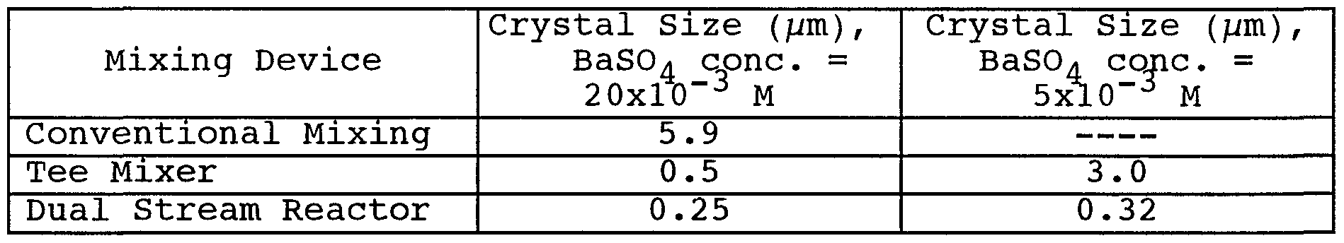
- Example 7 is provided to show the ability of the high pressure dual stream reactor to reduce crystal size of a precipitated product as compared to other mixing devices .
- the precipitation of barium sulfate (barite) is examined in this example.
- Barium sulfate is a simple salt which can be precipitated by the mixing of barium nitrate with sodium sulfate.
- the crystallite size of the product is well known to be based on the quality of mixing employed during the precipitation. Experiments were carried out using solutions to produce either 20x10 M or 5x10 —3 M BaS0 4 slurry product.
- the barium nitrate and sodium sulfate solutions were added to the reservoirs of the first and second pump, respectively.
- the operating pressure of the pumps was equal to 15 kpsi, corresponding to a flow rate of 300 ml/min for each pump.
- the reaction chamber shown in Fig. 2C was used in this experiment.
- the crystal size of the barite was measured in solution by laser light scattering, and the values are presented in Table 3.
- the use of the dual stream high pressure reactor leads to a reduction in crystal size of BaS0 by a factor of at least two as compared to other mixing devices .
Abstract
Description


Claims
Priority Applications (4)
| Application Number | Priority Date | Filing Date | Title |
|---|---|---|---|
| AU86867/98A AU8686798A (en) | 1997-08-05 | 1998-08-05 | Multiple stream high pressure mixer/reactor |
| DE69813254T DE69813254T2 (en) | 1997-08-05 | 1998-08-05 | HIGH PRESSURE MIXER REACTOR WITH MULTIPLE FLOWS |
| EP98938318A EP1011856B1 (en) | 1997-08-05 | 1998-08-05 | Multiple stream high pressure mixer/reactor |
| CA002299284A CA2299284C (en) | 1997-08-05 | 1998-08-05 | Multiple stream high pressure mixer/reactor |
Applications Claiming Priority (2)
| Application Number | Priority Date | Filing Date | Title |
|---|---|---|---|
| US90644697A | 1997-08-05 | 1997-08-05 | |
| US08/906,446 | 1997-08-05 |
Publications (1)
| Publication Number | Publication Date |
|---|---|
| WO1999007466A1 true WO1999007466A1 (en) | 1999-02-18 |
Family
ID=25422464
Family Applications (1)
| Application Number | Title | Priority Date | Filing Date |
|---|---|---|---|
| PCT/US1998/016180 WO1999007466A1 (en) | 1997-08-05 | 1998-08-05 | Multiple stream high pressure mixer/reactor |
Country Status (6)
| Country | Link |
|---|---|
| US (2) | US6221332B1 (en) |
| EP (1) | EP1011856B1 (en) |
| AU (1) | AU8686798A (en) |
| CA (1) | CA2299284C (en) |
| DE (1) | DE69813254T2 (en) |
| WO (1) | WO1999007466A1 (en) |
Cited By (12)
| Publication number | Priority date | Publication date | Assignee | Title |
|---|---|---|---|---|
| WO2005018687A2 (en) * | 2003-08-19 | 2005-03-03 | Resolution Chemicals Limited | Particle-size reduction apparatus, and use thereof |
| US7644880B2 (en) | 2004-12-16 | 2010-01-12 | Resolution Chemicals Limited | Particle-size reduction apparatus, and use thereof |
| US8187554B2 (en) | 2008-04-23 | 2012-05-29 | Microfluidics International Corporation | Apparatus and methods for nanoparticle generation and process intensification of transport and reaction systems |
| US9079140B2 (en) | 2011-04-13 | 2015-07-14 | Microfluidics International Corporation | Compact interaction chamber with multiple cross micro impinging jets |
| US9199209B2 (en) | 2011-04-13 | 2015-12-01 | Microfluidics International Corporation | Interaction chamber with flow inlet optimization |
| EP3117898A1 (en) * | 2015-07-15 | 2017-01-18 | i2 Gesellschaft für Innovation mbH | Preparation of a mixed catalyst |
| WO2017193725A1 (en) * | 2016-05-10 | 2017-11-16 | 中国恩菲工程技术有限公司 | System and method for treating cadmium-containing solution |
| WO2017193724A1 (en) * | 2016-05-10 | 2017-11-16 | 中国恩菲工程技术有限公司 | System and method for treating copper-containing solution |
| WO2018109593A1 (en) * | 2016-12-12 | 2018-06-21 | Ecole Polytechnique Federale De Lausanne (Epfl) | Nanoparticles and method for producing uniform silicate-based nanoparticles |
| CN109477053A (en) * | 2016-07-22 | 2019-03-15 | 日产化学株式会社 | The manufacturing method and manufacturing device of liquid culture medium composition |
| WO2019091259A1 (en) * | 2017-11-07 | 2019-05-16 | 原初科技(北京)有限公司 | Method and system for recycling carbon dioxide |
| US10350556B2 (en) | 2011-01-07 | 2019-07-16 | Microfluidics International Corporation | Low holdup volume mixing chamber |
Families Citing this family (107)
| Publication number | Priority date | Publication date | Assignee | Title |
|---|---|---|---|---|
| DE19927554C2 (en) * | 1999-06-16 | 2002-12-19 | Inst Mikrotechnik Mainz Gmbh | micromixer |
| US7708749B2 (en) | 2000-12-20 | 2010-05-04 | Fox Hollow Technologies, Inc. | Debulking catheters and methods |
| US6299622B1 (en) | 1999-08-19 | 2001-10-09 | Fox Hollow Technologies, Inc. | Atherectomy catheter with aligned imager |
| US7713279B2 (en) | 2000-12-20 | 2010-05-11 | Fox Hollow Technologies, Inc. | Method and devices for cutting tissue |
| US8328829B2 (en) | 1999-08-19 | 2012-12-11 | Covidien Lp | High capacity debulking catheter with razor edge cutting window |
| US7887556B2 (en) | 2000-12-20 | 2011-02-15 | Fox Hollow Technologies, Inc. | Debulking catheters and methods |
| DE60144107D1 (en) | 2000-12-20 | 2011-04-07 | Fox Hollow Technologies Inc | REDUCTION CATHETER |
| US20050048126A1 (en) * | 2000-12-22 | 2005-03-03 | Barrett Rabinow | Formulation to render an antimicrobial drug potent against organisms normally considered to be resistant to the drug |
| US6951656B2 (en) | 2000-12-22 | 2005-10-04 | Baxter International Inc. | Microprecipitation method for preparing submicron suspensions |
| US9700866B2 (en) * | 2000-12-22 | 2017-07-11 | Baxter International Inc. | Surfactant systems for delivery of organic compounds |
| US6884436B2 (en) * | 2000-12-22 | 2005-04-26 | Baxter International Inc. | Method for preparing submicron particle suspensions |
| GB0103441D0 (en) * | 2001-02-13 | 2001-03-28 | Secr Defence | Microchannel device |
| US7914755B2 (en) * | 2001-04-12 | 2011-03-29 | Eestor, Inc. | Method of preparing ceramic powders using chelate precursors |
| US20020189947A1 (en) * | 2001-06-13 | 2002-12-19 | Eksigent Technologies Llp | Electroosmotic flow controller |
| US7465382B2 (en) * | 2001-06-13 | 2008-12-16 | Eksigent Technologies Llc | Precision flow control system |
| US20030119282A1 (en) * | 2001-09-20 | 2003-06-26 | Takayasu Yamazaki | Method for producing semiconductor fine particles |
| JP2003095656A (en) * | 2001-09-20 | 2003-04-03 | Fuji Photo Film Co Ltd | Method of manufacturing semiconductive fine particle |
| IL160570A0 (en) * | 2001-09-26 | 2004-07-25 | Baxter Int | Preparation of submicron sized nanoparticles via dispersion and solvent or liquid phase removal |
| US20060003012A9 (en) | 2001-09-26 | 2006-01-05 | Sean Brynjelsen | Preparation of submicron solid particle suspensions by sonication of multiphase systems |
| US7112340B2 (en) * | 2001-10-19 | 2006-09-26 | Baxter International Inc. | Compositions of and method for preparing stable particles in a frozen aqueous matrix |
| US6693057B1 (en) * | 2002-03-22 | 2004-02-17 | Sud-Chemie Inc. | Water gas shift catalyst |
| US20030199595A1 (en) * | 2002-04-22 | 2003-10-23 | Kozyuk Oleg V. | Device and method of creating hydrodynamic cavitation in fluids |
| AU2003302462A1 (en) * | 2002-05-06 | 2004-06-18 | Tione Buranda | Bead-based detection of ligand-gpcr-g protein complexes |
| US6910797B2 (en) * | 2002-08-14 | 2005-06-28 | Hewlett-Packard Development, L.P. | Mixing device having sequentially activatable circulators |
| US20050098578A1 (en) * | 2002-09-13 | 2005-05-12 | Ford Motor Company | System for dispensing reactant mixtures |
| JP4809586B2 (en) * | 2003-03-05 | 2011-11-09 | 富士フイルム株式会社 | Method for producing magnetic particles |
| US7511079B2 (en) * | 2003-03-24 | 2009-03-31 | Baxter International Inc. | Methods and apparatuses for the comminution and stabilization of small particles |
| US8246640B2 (en) | 2003-04-22 | 2012-08-21 | Tyco Healthcare Group Lp | Methods and devices for cutting tissue at a vascular location |
| EP1652515A1 (en) * | 2003-08-06 | 2006-05-03 | Eisai Co., Ltd. | Process for producing drug ultramicroparticle and apparatus therefor |
| JP2005068125A (en) * | 2003-08-21 | 2005-03-17 | Rohm & Haas Co | Method for preparing biocide-blended material |
| JP4025735B2 (en) * | 2003-08-21 | 2007-12-26 | ローム アンド ハース カンパニー | Method for treating aqueous systems |
| WO2005077337A2 (en) * | 2004-02-05 | 2005-08-25 | Baxter International Inc. | Dispersions prepared by use of self-stabilizing agents |
| SG120172A1 (en) * | 2004-08-10 | 2006-03-28 | Beng Lai Koh | Mixing apparatus |
| CN101115548A (en) * | 2004-12-08 | 2008-01-30 | 丹佛斯公司 | Bubble-tolerant micro-mixers |
| US7422360B2 (en) * | 2005-02-23 | 2008-09-09 | Cavitech Holdings, Llc | Fluid impingement mixing device |
| JP2008543842A (en) * | 2005-06-14 | 2008-12-04 | バクスター インターナショナル インコーポレイテッド | Pharmaceutical formulations for minimizing drug-drug interactions |
| US20060280787A1 (en) * | 2005-06-14 | 2006-12-14 | Baxter International Inc. | Pharmaceutical formulation of the tubulin inhibitor indibulin for oral administration with improved pharmacokinetic properties, and process for the manufacture thereof |
| US20090268548A1 (en) * | 2005-08-11 | 2009-10-29 | Eksigent Technologies, Llc | Microfluidic systems, devices and methods for reducing diffusion and compliance effects at a fluid mixing region |
| US7749376B2 (en) * | 2005-08-15 | 2010-07-06 | Sud-Chemie Inc. | Process for sulfur adsorption using copper-containing catalyst |
| US20070044824A1 (en) * | 2005-09-01 | 2007-03-01 | Scott William Capeci | Processing system and method of processing |
| US8652705B2 (en) * | 2005-09-26 | 2014-02-18 | W.L. Gore & Associates, Inc. | Solid polymer electrolyte and process for making same |
| EP1954245A2 (en) * | 2005-11-15 | 2008-08-13 | Baxter International Inc. | Compositions of lipoxygenase inhibitors |
| US20070140046A1 (en) * | 2005-12-20 | 2007-06-21 | Imation Corp. | Multiple-stream annular fluid processor |
| US20070276419A1 (en) | 2006-05-26 | 2007-11-29 | Fox Hollow Technologies, Inc. | Methods and devices for rotating an active element and an energy emitter on a catheter |
| US7993611B2 (en) * | 2006-08-02 | 2011-08-09 | Eestor, Inc. | Method of preparing ceramic powders using ammonium oxalate |
| US8853116B2 (en) * | 2006-08-02 | 2014-10-07 | Eestor, Inc. | Method of preparing ceramic powders |
| US8183184B2 (en) | 2006-09-05 | 2012-05-22 | University Of Kansas | Polyelectrolyte complexes for oil and gas applications |
| US20080105316A1 (en) * | 2006-10-18 | 2008-05-08 | Imation Corp. | Multiple fluid product stream processing |
| US20090152176A1 (en) * | 2006-12-23 | 2009-06-18 | Baxter International Inc. | Magnetic separation of fine particles from compositions |
| GB0705159D0 (en) | 2007-03-19 | 2007-04-25 | Prosonix Ltd | Process for making crystals |
| US8426467B2 (en) * | 2007-05-22 | 2013-04-23 | Baxter International Inc. | Colored esmolol concentrate |
| US20080293814A1 (en) * | 2007-05-22 | 2008-11-27 | Deepak Tiwari | Concentrate esmolol |
| US8722736B2 (en) * | 2007-05-22 | 2014-05-13 | Baxter International Inc. | Multi-dose concentrate esmolol with benzyl alcohol |
| US7856737B2 (en) * | 2007-08-28 | 2010-12-28 | Mathews Company | Apparatus and method for reducing a moisture content of an agricultural product |
| WO2009120247A2 (en) * | 2007-12-27 | 2009-10-01 | The Ohio State University Research Foundation | Lipid nanoparticle compositions and methods of making and using the same |
| US8784440B2 (en) | 2008-02-25 | 2014-07-22 | Covidien Lp | Methods and devices for cutting tissue |
| WO2010045226A2 (en) | 2008-10-13 | 2010-04-22 | Fox Hollow Technologies, Inc. | Devices and methods for manipulating a catheter shaft |
| SE534535C2 (en) * | 2008-12-29 | 2011-09-27 | Alfa Laval Corp Ab | Pump device with two pump units, use and method for controlling one |
| US20100285316A1 (en) * | 2009-02-27 | 2010-11-11 | Eestor, Inc. | Method of Preparing Ceramic Powders |
| KR20110123782A (en) * | 2009-02-27 | 2011-11-15 | 에스톨, 인코포레이티드 | Reaction tube and hydrothermal processing for the wet chemical co-precipitation of oxide powders |
| KR101323553B1 (en) | 2009-04-29 | 2013-10-29 | 코비디엔 엘피 | Methods and devices for cutting and abrading tissue |
| JP5281195B2 (en) | 2009-05-14 | 2013-09-04 | コヴィディエン リミテッド パートナーシップ | Atherotomy catheter that can be easily cleaned and method of use |
| US8496677B2 (en) | 2009-12-02 | 2013-07-30 | Covidien Lp | Methods and devices for cutting tissue |
| IN2012DN04977A (en) | 2009-12-11 | 2015-09-25 | Tyco Healthcare | |
| BR112012031907A2 (en) | 2010-06-14 | 2020-08-04 | Covidien Lp | material removal device. |
| US20120009347A1 (en) * | 2010-07-07 | 2012-01-12 | Applied Materials, Inc. | Precise temperature control for teos application by heat transfer fluid |
| US8968873B2 (en) | 2010-08-13 | 2015-03-03 | University Of Connecticut | Co-flow microfluidic device for polymersome formation |
| KR101518147B1 (en) | 2010-10-28 | 2015-05-06 | 코비디엔 엘피 | Material removal device and method of use |
| CA2817213C (en) | 2010-11-11 | 2016-06-14 | Covidien Lp | Flexible debulking catheters with imaging and methods of use and manufacture |
| CA2729457C (en) | 2011-01-27 | 2013-08-06 | Fort Hills Energy L.P. | Process for integration of paraffinic froth treatment hub and a bitumen ore mining and extraction facility |
| CA2906715C (en) | 2011-02-25 | 2016-07-26 | Fort Hills Energy L.P. | Process for treating high paraffin diluted bitumen |
| CA2931815C (en) | 2011-03-01 | 2020-10-27 | Fort Hills Energy L.P. | Process and unit for solvent recovery from solvent diluted tailings derived from bitumen froth treatment |
| CA2733862C (en) | 2011-03-04 | 2014-07-22 | Fort Hills Energy L.P. | Process and system for solvent addition to bitumen froth |
| CA2735311C (en) | 2011-03-22 | 2013-09-24 | Fort Hills Energy L.P. | Process for direct steam injection heating of oil sands bitumen froth |
| US10289127B2 (en) | 2011-04-13 | 2019-05-14 | Autoquip, Inc. | Mixed fluid delivery system |
| CA2737410C (en) | 2011-04-15 | 2013-10-15 | Fort Hills Energy L.P. | Heat recovery for bitumen froth treatment plant integration with sealed closed-loop cooling circuit |
| CA3077966C (en) | 2011-04-28 | 2022-11-22 | Fort Hills Energy L.P. | Recovery of solvent from diluted tailings by feeding a solvent diluted tailings to a digester device |
| CA2857718C (en) | 2011-05-04 | 2015-07-07 | Fort Hills Energy L.P. | Turndown process for a bitumen froth treatment operation |
| CA2740935C (en) | 2011-05-18 | 2013-12-31 | Fort Hills Energy L.P. | Enhanced temperature control of bitumen froth treatment process |
| KR101580583B1 (en) * | 2011-08-08 | 2015-12-29 | 재단법인 한국계면공학연구소 | Device and methods for accelerating reaction of liquids having heterogeneous phase |
| JP5806407B2 (en) | 2011-09-01 | 2015-11-10 | コヴィディエン リミテッド パートナーシップ | Catheter with helical drive shaft and manufacturing method |
| US9295978B2 (en) | 2012-02-15 | 2016-03-29 | Basf Corporation | Catalyst and method for the direct synthesis of dimethyl ether from synthesis gas |
| US9719521B2 (en) | 2012-06-18 | 2017-08-01 | Flowserve Management Company | Fluid intensifier for a dry gas seal system |
| US9532844B2 (en) | 2012-09-13 | 2017-01-03 | Covidien Lp | Cleaning device for medical instrument and method of use |
| US9943329B2 (en) | 2012-11-08 | 2018-04-17 | Covidien Lp | Tissue-removing catheter with rotatable cutter |
| CN104512923A (en) * | 2013-09-30 | 2015-04-15 | 上海梅山钢铁股份有限公司 | Preparation method of nano-barium sulfate |
| US10128087B2 (en) | 2014-04-07 | 2018-11-13 | Lam Research Corporation | Configuration independent gas delivery system |
| WO2015200702A1 (en) | 2014-06-27 | 2015-12-30 | Covidien Lp | Cleaning device for catheter and catheter including the same |
| US10557197B2 (en) | 2014-10-17 | 2020-02-11 | Lam Research Corporation | Monolithic gas distribution manifold and various construction techniques and use cases therefor |
| WO2016085743A1 (en) | 2014-11-24 | 2016-06-02 | President And Fellows Of Harvard College | Methods and systems for encapsulation of actives within droplets and other compartments |
| US9938478B2 (en) | 2014-12-12 | 2018-04-10 | Sustainable Waste Power Systems, Inc. | Devolatilization system and methods thereof |
| US10393106B2 (en) * | 2014-12-15 | 2019-08-27 | Sustainable Waste Power Systems, Inc. | Pumps, pump assemblies, and methods of pumping fluids |
| US10314667B2 (en) | 2015-03-25 | 2019-06-11 | Covidien Lp | Cleaning device for cleaning medical instrument |
| US10292721B2 (en) | 2015-07-20 | 2019-05-21 | Covidien Lp | Tissue-removing catheter including movable distal tip |
| US10022689B2 (en) * | 2015-07-24 | 2018-07-17 | Lam Research Corporation | Fluid mixing hub for semiconductor processing tool |
| US10314664B2 (en) | 2015-10-07 | 2019-06-11 | Covidien Lp | Tissue-removing catheter and tissue-removing element with depth stop |
| US10215317B2 (en) | 2016-01-15 | 2019-02-26 | Lam Research Corporation | Additively manufactured gas distribution manifold |
| CN106732618A (en) * | 2017-01-17 | 2017-05-31 | 西南化工研究设计院有限公司 | A kind of method that water phase decomposition prepares copper-based catalysts |
| KR102343575B1 (en) | 2017-01-17 | 2021-12-27 | 마이크로플루이딕스 인터내셔날 코퍼레이션 | Apparatus and method using high pressure double check valve |
| PL238324B1 (en) * | 2017-08-29 | 2021-08-09 | Inst Chemii Organicznej Polskiej Akademii Nauk | Flow apparatus intended to continuously conduct processes under high pressure |
| PT110585B (en) | 2018-02-22 | 2021-04-22 | Hovione Farmaciencia Sa | PROCESS OF CONTINUOUS PARTICLE PRODUCTION UNDERSTANDING ATOMIZATION DRYING WITH CONTINUOUS PREPARATION OF THE ATOMIZATION SOLUTION |
| CA2997848C (en) * | 2018-03-09 | 2019-02-12 | Mazza Innovation, Ltd. | Multiple-stream pressurized low polarity water extraction apparatus, system, and methods of use |
| JP7320852B2 (en) * | 2018-06-22 | 2023-08-04 | デルファイ サイエンティフィック、エルエルシー | Devices, systems, and methods for continuous production of nanomaterials and high-purity chemicals |
| CN109507881A (en) * | 2018-11-08 | 2019-03-22 | 广东道氏技术股份有限公司 | A kind of ceramics seep the Distributed Predictive Control method and system of flower ink preparation process |
| CN110538620B (en) * | 2018-11-14 | 2021-10-15 | 北京北方华创微电子装备有限公司 | Pressure control system and pressure control method of reaction chamber |
| CN112426984A (en) * | 2020-11-16 | 2021-03-02 | 台州智子科技有限公司 | Microreactor with bamboo-shaped microstructure |
| CN117500573A (en) * | 2021-06-02 | 2024-02-02 | 斯凯孚Mfr科技公司 | Method and system for oil purification |
Citations (6)
| Publication number | Priority date | Publication date | Assignee | Title |
|---|---|---|---|---|
| US4533254A (en) * | 1981-04-17 | 1985-08-06 | Biotechnology Development Corporation | Apparatus for forming emulsions |
| WO1988003052A1 (en) * | 1986-10-21 | 1988-05-05 | Nordson Corporation | Liquid mixing and extruding or spraying method and apparatus |
| US5019547A (en) * | 1989-04-24 | 1991-05-28 | Institut Francais Du Petrole | Process for preparing precursors of catalysts containing copper, aluminum and zinc, usable for the synthesis and the decomposition of methanol and catalysts obtained from the precursors |
| JPH03275148A (en) * | 1990-03-23 | 1991-12-05 | Kao Corp | Production of deposited catalyst |
| WO1994004263A1 (en) * | 1992-08-18 | 1994-03-03 | Worcester Polytechnic Institute | Preparation of solid state materials |
| WO1996026000A1 (en) * | 1995-02-23 | 1996-08-29 | Jiann Fu Yang Frank | Mixing apparatus for microflow gradient pumping |
Family Cites Families (5)
| Publication number | Priority date | Publication date | Assignee | Title |
|---|---|---|---|---|
| US4113843A (en) * | 1974-07-03 | 1978-09-12 | Yakov Volfovich Mirsky | Process for the production of zeolites in the form of binderless spherical granules |
| US4750941A (en) * | 1986-01-14 | 1988-06-14 | Horst Gerich | Liquid metering, mixing, dispensing, testing and purging method and apparatus |
| US5246899A (en) * | 1991-08-16 | 1993-09-21 | Amoco Corporation | Simplified preparation of hydrotalcite-type clays |
| US5615949A (en) * | 1995-08-08 | 1997-04-01 | Woodbridge Foam Corporation | High pressure mixing system and process for producing foamed isocyanate-based polymers containing filler material |
| US5927852A (en) * | 1997-12-01 | 1999-07-27 | Minnesota Mining And Manfacturing Company | Process for production of heat sensitive dispersions or emulsions |
-
1998
- 1998-08-05 CA CA002299284A patent/CA2299284C/en not_active Expired - Lifetime
- 1998-08-05 DE DE69813254T patent/DE69813254T2/en not_active Expired - Fee Related
- 1998-08-05 AU AU86867/98A patent/AU8686798A/en not_active Abandoned
- 1998-08-05 EP EP98938318A patent/EP1011856B1/en not_active Expired - Lifetime
- 1998-08-05 US US09/129,359 patent/US6221332B1/en not_active Expired - Lifetime
- 1998-08-05 WO PCT/US1998/016180 patent/WO1999007466A1/en active IP Right Grant
- 1998-08-05 US US09/129,294 patent/US6159442A/en not_active Expired - Lifetime
Patent Citations (6)
| Publication number | Priority date | Publication date | Assignee | Title |
|---|---|---|---|---|
| US4533254A (en) * | 1981-04-17 | 1985-08-06 | Biotechnology Development Corporation | Apparatus for forming emulsions |
| WO1988003052A1 (en) * | 1986-10-21 | 1988-05-05 | Nordson Corporation | Liquid mixing and extruding or spraying method and apparatus |
| US5019547A (en) * | 1989-04-24 | 1991-05-28 | Institut Francais Du Petrole | Process for preparing precursors of catalysts containing copper, aluminum and zinc, usable for the synthesis and the decomposition of methanol and catalysts obtained from the precursors |
| JPH03275148A (en) * | 1990-03-23 | 1991-12-05 | Kao Corp | Production of deposited catalyst |
| WO1994004263A1 (en) * | 1992-08-18 | 1994-03-03 | Worcester Polytechnic Institute | Preparation of solid state materials |
| WO1996026000A1 (en) * | 1995-02-23 | 1996-08-29 | Jiann Fu Yang Frank | Mixing apparatus for microflow gradient pumping |
Non-Patent Citations (2)
| Title |
|---|
| HOEPPENER R H ET AL: "PREPARATION AND CHARACTERIZATION OF STABLE COPPER/ZINC OXIDE/ ALUMINA CATALYSTS FOR METHANOL SYNTHESIS", APPLIED CATALYSIS, vol. 25, 1 January 1986 (1986-01-01), pages 109 - 119, XP000578632 * |
| PATENT ABSTRACTS OF JAPAN vol. 16, no. 86 (C - 0916) 3 March 1992 (1992-03-03) * |
Cited By (29)
| Publication number | Priority date | Publication date | Assignee | Title |
|---|---|---|---|---|
| WO2005018687A3 (en) * | 2003-08-19 | 2005-04-21 | Resolution Chemicals Ltd | Particle-size reduction apparatus, and use thereof |
| US7600703B2 (en) | 2003-08-19 | 2009-10-13 | Resolution Chemicals Limited | Particle-size reduction apparatus and use thereof |
| US7861957B2 (en) | 2003-08-19 | 2011-01-04 | Resolution Chemicals Limited | Particle-size reduction apparatus, and use thereof |
| WO2005018687A2 (en) * | 2003-08-19 | 2005-03-03 | Resolution Chemicals Limited | Particle-size reduction apparatus, and use thereof |
| US9327039B2 (en) | 2004-12-16 | 2016-05-03 | Resolution Chemicals Limited | Particle size reduction apparatus, and use thereof |
| US7644880B2 (en) | 2004-12-16 | 2010-01-12 | Resolution Chemicals Limited | Particle-size reduction apparatus, and use thereof |
| US8052076B2 (en) | 2004-12-16 | 2011-11-08 | Resolution Chemicals Limited | Particle-size reduction apparatus, and use thereof |
| US8187554B2 (en) | 2008-04-23 | 2012-05-29 | Microfluidics International Corporation | Apparatus and methods for nanoparticle generation and process intensification of transport and reaction systems |
| US8367004B2 (en) | 2008-04-23 | 2013-02-05 | Microfluidics International Corporation | Apparatus and methods for nanoparticle generation and process intensification of transport and reaction systems |
| US10350556B2 (en) | 2011-01-07 | 2019-07-16 | Microfluidics International Corporation | Low holdup volume mixing chamber |
| US10898869B2 (en) | 2011-01-07 | 2021-01-26 | Microfluidics International Corporation | Low holdup volume mixing chamber |
| US9199209B2 (en) | 2011-04-13 | 2015-12-01 | Microfluidics International Corporation | Interaction chamber with flow inlet optimization |
| US9895669B2 (en) | 2011-04-13 | 2018-02-20 | Microfluidics International Corporation | Interaction chamber with flow inlet optimization |
| US9931600B2 (en) | 2011-04-13 | 2018-04-03 | Microfluidics International Corporation | Compact interaction chamber with multiple cross micro impinging jets |
| US9079140B2 (en) | 2011-04-13 | 2015-07-14 | Microfluidics International Corporation | Compact interaction chamber with multiple cross micro impinging jets |
| EP3117898A1 (en) * | 2015-07-15 | 2017-01-18 | i2 Gesellschaft für Innovation mbH | Preparation of a mixed catalyst |
| WO2017193725A1 (en) * | 2016-05-10 | 2017-11-16 | 中国恩菲工程技术有限公司 | System and method for treating cadmium-containing solution |
| WO2017193724A1 (en) * | 2016-05-10 | 2017-11-16 | 中国恩菲工程技术有限公司 | System and method for treating copper-containing solution |
| KR20190027924A (en) * | 2016-07-22 | 2019-03-15 | 닛산 가가쿠 가부시키가이샤 | Method and apparatus for producing a liquid medium composition |
| JPWO2018016622A1 (en) * | 2016-07-22 | 2019-05-16 | 日産化学株式会社 | Method and apparatus for producing liquid medium composition |
| CN109477053A (en) * | 2016-07-22 | 2019-03-15 | 日产化学株式会社 | The manufacturing method and manufacturing device of liquid culture medium composition |
| EP3483254A4 (en) * | 2016-07-22 | 2019-07-17 | Nissan Chemical Corporation | Method and device for producing liquid culture medium composition |
| KR102387723B1 (en) * | 2016-07-22 | 2022-04-18 | 닛산 가가쿠 가부시키가이샤 | Manufacturing method and manufacturing apparatus of a liquid medium composition |
| TWI763690B (en) * | 2016-07-22 | 2022-05-11 | 日商日產化學工業股份有限公司 | Method and apparatus for producing a liquid medium composition |
| JP2022130591A (en) * | 2016-07-22 | 2022-09-06 | 日産化学株式会社 | Method and apparatus for manufacturing liquid medium composition |
| US10815128B2 (en) | 2016-12-12 | 2020-10-27 | Ecole Polytechnique Federale De Lausanne (Epfl) | Nanoparticles and method for producing uniform silicate-based nanoparticles |
| WO2018109593A1 (en) * | 2016-12-12 | 2018-06-21 | Ecole Polytechnique Federale De Lausanne (Epfl) | Nanoparticles and method for producing uniform silicate-based nanoparticles |
| WO2019091259A1 (en) * | 2017-11-07 | 2019-05-16 | 原初科技(北京)有限公司 | Method and system for recycling carbon dioxide |
| US11919778B2 (en) | 2017-11-07 | 2024-03-05 | Yuanchu Technology (Beijing) Co., Ltd. | Method and system for recycling carbon dioxide |
Also Published As
| Publication number | Publication date |
|---|---|
| EP1011856B1 (en) | 2003-04-09 |
| US6159442A (en) | 2000-12-12 |
| EP1011856A1 (en) | 2000-06-28 |
| CA2299284C (en) | 2008-07-08 |
| US6221332B1 (en) | 2001-04-24 |
| AU8686798A (en) | 1999-03-01 |
| CA2299284A1 (en) | 1999-02-18 |
| DE69813254T2 (en) | 2004-04-01 |
| DE69813254D1 (en) | 2003-05-15 |
Similar Documents
| Publication | Publication Date | Title |
|---|---|---|
| EP1011856B1 (en) | Multiple stream high pressure mixer/reactor | |
| Fitchett et al. | Effect of mixing on the precipitation of barium sulfate in an MSMPR reactorssss | |
| US7238331B2 (en) | Process for producing nano-powders and powders of nano-particle loose aggregate | |
| EP1971550B1 (en) | Nanoparticles, and a method of sol-gel processing | |
| Ying et al. | A high throughput methodology for continuous preparation of monodispersed nanocrystals in microfluidic reactors | |
| JP6823831B2 (en) | Nanocrystal manufacturing method and nanocrystal manufacturing equipment | |
| KR100621675B1 (en) | Process for producing nanometer grade powders | |
| Aimable et al. | Precipitation of Nanosized and Nanostructured Powders: Process Intensification and Scale‐Out Using a Segmented Flow Tubular Reactor (SFTR) | |
| CN101525239A (en) | Method for synthesizing Bi0.5Na0.5TiO3 spheroidal particles by microwave hydrothermal method | |
| Hu et al. | Development of an automated multi-stage continuous reactive crystallization system with in-line PATs for high viscosity process | |
| CA2591293A1 (en) | Production of oxidic nanoparticles | |
| GB2168334A (en) | Production of complex metal hydroxide powders | |
| US11724241B2 (en) | Constant shear continuous reactor device | |
| Liu et al. | Solvothermal synthesis of zirconia nanomaterials: latest developments and future | |
| WO2009132198A2 (en) | Method for making designed particle size distributions by flow manufacturing | |
| CN108997126A (en) | A kind of synthesis technology of the Barium trinitroresorcinate based on block Flow Technique | |
| N Begletsova et al. | Synthesis of copper nanoparticles stabilized with cetylpyridinium chloride micelles | |
| You et al. | Synthesis of uniformly spherical bayerite from a sodium aluminate solution reacted with sodium bicarbonate | |
| Uehara-Nagamine et al. | Effect of process variables on the single-feed semibatch precipitation of barium sulphate | |
| Liu et al. | High-throughput synthesis of uniform Mg (OH) 2 nanoparticles in an oscillating feedback minireactor designed by the selective dimension scale-out method | |
| Miller et al. | Solubility and mass-transfer coefficients for hydrogen and carbon monoxide in n-octacosane | |
| US7115764B2 (en) | Mechanical shear based synthesis of alumoxane nanoparticles | |
| Chen et al. | One droplet reaction for synthesis of multi-sized nanoparticles | |
| Wang et al. | GGGGGGGG LLL GGGGG SG GGGGGG SGGGGGGGS G LLLSaGGGGGS | |
| Wang et al. | Sol preparation from zirconyl chloride octahydrate in amine‐ammonia solution |
Legal Events
| Date | Code | Title | Description |
|---|---|---|---|
| AK | Designated states |
Kind code of ref document: A1 Designated state(s): AL AM AT AU AZ BA BB BG BR BY CA CH CN CU CZ DE DK EE ES FI GB GE GH GM HR HU ID IL IS JP KE KG KP KR KZ LC LK LR LS LT LU LV MD MG MK MN MW MX NO NZ PL PT RO RU SD SE SG SI SK SL TJ TM TR TT UA UG UZ VN YU ZW |
|
| AL | Designated countries for regional patents |
Kind code of ref document: A1 Designated state(s): GH GM KE LS MW SD SZ UG ZW AM AZ BY KG KZ MD RU TJ TM AT BE CH CY DE DK ES FI FR GB GR IE IT LU MC NL PT SE BF BJ CF CG CI CM GA GN GW ML MR NE SN TD TG |
|
| DFPE | Request for preliminary examination filed prior to expiration of 19th month from priority date (pct application filed before 20040101) | ||
| 121 | Ep: the epo has been informed by wipo that ep was designated in this application | ||
| ENP | Entry into the national phase |
Ref document number: 2299284 Country of ref document: CA Ref country code: CA Ref document number: 2299284 Kind code of ref document: A Format of ref document f/p: F |
|
| NENP | Non-entry into the national phase |
Ref country code: KR |
|
| WWE | Wipo information: entry into national phase |
Ref document number: 1998938318 Country of ref document: EP |
|
| REG | Reference to national code |
Ref country code: DE Ref legal event code: 8642 |
|
| WWP | Wipo information: published in national office |
Ref document number: 1998938318 Country of ref document: EP |
|
| WWG | Wipo information: grant in national office |
Ref document number: 1998938318 Country of ref document: EP |