Multiple Stage Mass Spectrometer
This application claims priority on U.S. Provisional Application No. 60/150,874, filed on August 26, 1999.
FIELD OF THE INVENTION
The invention generally relates to mass spectrometers and specifically to tandem mass spectrometers. More specifically the invention is directed to a mass spectrometry apparatus and method that provides an effective solution for multiple stage mass spectrometπc analysis and coupling of low resolution multiple stage mass spectrometry devices with external high-resolution mass spectrometers.
BACKGROUND OF THE INVENTION
Traditionally tandem mass spectrometers (MS-MS) have been employed to provide structural information for samples of interest. In MS-MS instruments, a first mass spectrometer is used to select a pπmary ion of interest, for example, a molecular ion of a particular biomolecular compound such as a peptide, and that ion is caused to fragment by increasing its internal energy, for example, by colliding the ion with a neutral molecule. A second mass spectrometer then analyzes the spectrum of fragment ions, and often the structure of the pπmary ion can be determined by interpreting the fragmentation pattern. The MS-MS instrument improves the recognition of a compound with a known pattern of fragmentation and also improves specificity of detection in complex mixtures, where different components give overlapping peaks m simple MS. In the majoπty of applications the detection limit is defined by the level of chemical noise. Drug metabolism studies and protein recognition m proteome studies are good examples. Frequently, MS-MS techniques can also improve the detection limit. When analyzing certain samples it is often desirable to conduct further analyses of fragments produced from the oπgmally selected ion, and such further analyses consist of repeated sequences of mass to charge ratio (m/z) isolation and fragmentation. In some cases different m/z fragments deπved from a single parent ion are further analyzed, and in other cases a single m/z fragment is subjected to a succession of "n" mass spectrometπc steps to yield relevant information regarding the oπgmal parent ion. This continued mass spectrometπc analyses is referred to in the art as MSn analyses. Vaπous types of mass spectrometers have been employed to conduct MS" analysis as discussed below.
A three-dimensional ion trap (3-D IT) is one of the most flexible devices for MS-MS and multi- step (MSn) analysis. This trap is composed of a πng electrode and two end cap electrodes of special shape to create a quadrupolar distπbution of potential. Radio frequency (RF) and DC offset electπc potentials are applied between electrodes and cause ions to oscillate within the trap. By appropπately
selecting voltage parameters, ions of a specific mass/charge ratio can be made to have stable or unstable trajectoπes. In another implementation an additional (auxiliary) AC voltage is applied to the end-caps to induce resonant excitation of selected ions either for the purpose of ejecting the selected ions or for the purpose of inducing colhsional dissociation.
The 3-D ion trap is capable of single step mass spectrometπc analysis In such analysis ions are injected into the trap (or generated withm the trap), confined to the center of trap because of low energy collisions with an inert gas such as helium (typically at 1 mtorr pressure) and then sequentially ejected through the apertures in the end cap electrodes onto an external detector by raising the amplitude of the RF field. The same device could be used for a multi-step, i.e. MSn , analysis The ion trap isolates ions m a m/z window by rejecting other components, then fragments these isolated ions by AC excitation, then isolates resulting ion fragments in a m/z window and repeats such sequence (MS n operation) in a single cell. At the end of the sequence ions are resonantly ejected to acquire the mass spectrum of N-th generation fragments. The 3-D IT is vulnerable to sensitivity losses due to ion rejection and instability losses at the time of ion selection and fragmentation.
Fouπer transform ion cyclotron resonance mass spectrometry (FTMS) currently provides the most accurate measurement of ion mass to charge ratios with a demonstrated resolution m excess of 100,000. In FTMS, ions are either injected from outside the cell or created inside the cell and confined in the cell by a combination of static magnetic and electπc fields (Penning trap). The static magnetic and electπc field define the mass dependent frequency of cyclotron motion. This motion is excited by an oscillating electπc potential. After a short peπod the applied field is turned off. Amplifying and recording weak voltages induced on the cell plates by the ion's motion detects the frequency of ion motion and, thus, the m/z of the ion. Ions are selectively isolated or dissociated by varying the magnitude and frequency of the applied transverse RF electπc potential and the background neutral gas pressure. Repeated sequences of ion isolation and fragmentation (MSn operation) can be performed in a single cell. An FTMS is a "bulky" device occupying a large footpπnt and is also expensive due to the costs of the magnetic field. Moreover, an FTMS exhibits poor ion retention in MS" operation (relative
Currently, the most common form of tandem mass spectrometer is a tπple quadrupole, where both mass spectrometers are quadrupoles and an RF only quadrupole functions as a colhsional cell to enhance ion transport. Because of low scanning speed the instrument employs continuous ion sources like ESI and atmospheπc pressure chemical lonization (APCI). Since scanning the second mass
spectrometer would cause losses, the most effective way of using this instrument is monitoring of selected reactions. Drug metabolism studies are a good example where a known drug compound is measured in a rich biological matrix, like blood or urine. In those studies both parent and daughter fragment masses are known and the spectrometer is tuned on those specific masses. For more generic applications requiring scanning, the triple quadrupole instrument is a poor instrument choice because of its low speed, sensitivity, mass accuracy and resolution.
Recently hybrid instruments combining quadrupoles with time of flight analyzers (Q-TOF) have been described where the second quadrupole mass spectrometer is replaced by an orthogonal time of flight spectrometer (o-TOF). The o-TOF back end allows observation of all fragment ions at once and the acquisition of secondary spectra at high resolution and mass accuracy. In cases where the full mass range of daughter ions is required, for example, for peptide sequencing, the Q-TOF strongly surpasses the performance of the triple quadrupole. However, the Q-TOF suffers a 10 to a 100 fold loss in sensitivity as compared to a single quadrupole mass filter operating in selected reaction monitoring mode (monitoring single m/z). For the same reason the sensitivity of the Q-TOF is lower in the mode of "parent scan" where, again, the second MS is used to monitor a single m/z.
More recently, the quadrupole has been replaced by a linear ion trap (LIT). The quadrupole with electrostatic "plugs" is capable of trapping ions for long periods of time. The quadrupole field structure allows one to apply an arsenal of separation and excitation methods, developed in 3-D ion trap technology, combined with easy introduction and ejection of the ion beam out of the LIT. The LIT eliminates ion losses at selection and also can operate at poor vacuum conditions which reduces requirements on the pumping system. However, a limited resolution of ion selection, R< 200, has been demonstrated thus far.
All of the existing MS" devices suffer from a common drawback in that they do not provide a capability for storing results of multiple MS steps with the concomitant capability to explore multiple branches of fragmentation using the same ion material. The current state of the art is that the sequence of functional steps (selection, cooling, fragmentation and analysis) is done either "in-time" while keeping results in the same cell, as in ion trap and FTMS devices, or "in-space" with the ion beam constantly flowing, as in triple quadrupole, Q-TOF and LIT-TOF devices. In both cases selection of ions of interest automatically means rejection of all other components. As a result the existing instruments limit the number of multi-step MS analysis that can be carried out simply due to ion losses. It would therefore be desirable to improve the sensitivity of MS" analysis and thus provide a capability of
detailed sequencing and analysis of ultra low quantity sample in complex matrixes. It would also be desirable to produce a device with multiple cells for storing the results of each step of the MS" analysis and thereby provide a device with a high efficiency of selection and fragmentation.
SUMMARY OF THE INVENTION
The present invention overcomes the disadvantages and limitations of the prior art by providing a highly sensitive multiple stage (MSn) mass spectrometer and mass spectrometric method, capable of eliminating losses of ions during the isolation stage. Ions of interest are physically isolated (by m/z value) without rejecting ions of other m/z values, so that the selected ions may be dissociated, while the rest of the ion population is available for subsequent isolation, dissociation and mass spectrometric analysis of fragment ions.
A preferred embodiment of the invention includes a pulsed ion source coupled with a linear array of mass selective ion trap devices at least one of the traps being coupled to an external ion detector. Each ion trap device is configured with a storing cell for ion trapping interspersed between a pair of guarding cells, all aligned along a common axis, denoted in the following as the z direction (Figure 1). A combination of radio frequency (RF) and direct current (DC) voltages are applied to electrodes of the ion trap device to retain ions within the trapping (storing) cells. Each trapping cell has a sub-region in which the dynamical motion of the ion exhibits resonance frequencies along the z direction. These resonance frequencies are m/z-dependent so that the ion motion can be selectively excited by m/z value through the application of AC voltages to various electrodes of the ion trap device. The AC voltages can be combined with time-resolved changes in the applied DC voltages so that each individual trapping cell can be switched between ion trapping, mass selecting and ion fragmenting modes. Ions may be selectively transferred between traps of said linear array, and selectively dissociated within each trap of said linear array to enable a higher sensitivity MS" operation. The application of the RF, AC and DC voltages and the resulting modes of operation of the invention depend on specific embodiments of the general concept as will be described in detail below.
The present invention is applicable to all currently useful methods of ion generation. In one preferred embodiment the pulsed ion source comprises an intrinsically pulsed (MALDI) ion source. In another preferred embodiment the pulsed ion source comprises an electrospray (ESI) or an atmospheric pressure chemical ionization (APCI) ion source with a storing multipole guide (for example, an accumulating quadrupole), periodically injecting ions into the array of ion traps.
In accordance with embodiments of the invention, the final mass analysis of fragments of the n* generation of fragmentation can be done either by mass dependent ejection of ions from the last (i.e., furthest from the ion source) ion trap within the array of ion trap devices onto a detector or by introducing the entire ion content of any cell into an external mass spectrometer of conventional design. In one particular embodiment, the external mass spectrometer is a time-of-flight mass spectrometer (TOF MS). In a preferred case of this embodiment, ions are pulsed injected into an orthogonal TOF MS with a synchronized orthogonal pulsing to reduce so-called "duty-cycle" losses. In yet another particular case of the embodiment, the last cell of the linear ion trap serves as an acceleration stage for the TOF MS.
In yet another embodiment, the mass spectrum of ions and/or fragments is acquired by measuring the weak electric signal induced by ion oscillations on the confining electrodes that are part of the ion trap cells.
In accordance with the invention, each ion trapping device with the linear array of ion trapping devices can be generally classified by the nature of the linear approximation to the ion trapping field in the center of the device (the 'origin'). An ion trapping field of a certain linear approximation can be realized by multiple electrode geometries and applied AC and DC signals. In one preferred embodiment, the linear approximation to the ion trapping field generates a harmonic linear trap (HLT) device. In another preferred embodiment, the linear approximation to the ion trapping field generates a Paul trap device.
The origin of the HLT or Paul trap device is the point inside the trapping region where the electric field for trapping a single ion vanishes. In the vicinity of the origin for the HLT or Paul trap the equations of motion for a single ion can be approximated by a linear set of three 2nd order, ordinary differential equations of motion. The HLT class covers three-dimensional ion traps in which a harmonic oscillator equation governs one coordinate (by convention, the z coordinate) and Mathieu equations govern the x and y coordinates. The Paul trap class has Mathieu equations governing all three coordinates.
In a preferred embodiment, the HLT device is configured as a triplet of electrode cells. Each cell triplet consists of open parallelpiped cells surrounding an open parallelpiped trapping cell. In the linear array, a guarding cell is shared between adjacent HLT triplets. The guarding and storing cells are
distinguished by length, DC offset, z excitation voltages (dipolar) and function. In this embodiment the gate and trappmg cells share the radial frapping RF voltage.
In yet another preferred embodiment, for the purpose of achieving a higher resolution of mass selection, each cell of the linear array is a Paul trap. The basic electrode geometry for the Paul trap could be the same as the HLT discussed above or can be constructed using hollow cylinder cells interspersed between guarding plate electrodes. In each instance, unlike the HLT, the RF is applied only to the trapping (stonng) cells. A DC voltage is applied to both trapping and guarding cells and an AC signal (for exciting the z motion of the ions) is applied between the guarding and trapping cells.
A method of multiple step mass spectrometπc analysis according to the present invention includes pulsed introduction of an ion beam into one of a plurality of multiple communicating ion traps, combined with novel features including a) sampling of ions into the adjacent trap without losses of other components, b) stonng ion fragments of each generation in individual traps, and c) using stored ions for subsequent analysis of multiple fragmentation channels. Sampling a portion of the ions into an external mass spectrometer allows the extensive use of economic data-dependent algoπthms in the selective transfer and dissociation of ions in the device.
In accordance with a preferred embodiment, the method of selective ion transfer between trapping cells involves an array of either HLT or Paul trap devices and further involves applying an AC signal between the guarding and stonng cells (dipolar field local to the oπgin) with a single frequency equal to the resonant frequency of the ion's z motion. In one particular case of the embodiment, the applied AC signal has a time-dependent frequency that tracks the frequency shift m the ion's resonant z motion due to nonlinear electnc fields perturbing the ion's motion away from the oπgm.
In an array of HLT the selective transfer method can be improved by lowenng the DC barπer between ion traps once the ions of a predetermined m/z value are AC excited to the highest energy withm the ion population in the trap. It is advantageous to drop the DC barπer at a predetermined phase of ion oscillation.
One aspect of the above-described methods of selective ion transfer is that non-transferred ions are retained withm the ion trap for subsequent analysis. This is in contrast to conventional selection methods, where ions are isolated by the ejection of other components.
A method of ion fragmentation in accordance with one embodiment of the present invention is accomplished by accelerating ions between cells either by using a DC electπc field between cells or by resonant AC excitation of ions. Contrary to fragmentation within a Paul trap, the ion fragmentation m the HLT array is characteπzed by minimal ion losses due to the greater stability of ion motion m the radial direction.
BRIEF DESCRIPTION OF THE DRAWING FIGURES
Fig. 1 is a block-diagram of an embodiment of the invention. Fig. 2 is a flow chart of fragmentation channels, illustrating the concept of "branched MS"" analysis.
Fig. 3 A is a schematic diagram of one preferred embodiment of the invention. Fig. 3B is a schematic diagram of two different ion sources useful with the embodiment of Fig 3A. Fig. 3C is a schematic diagram showing the application of applied voltages useful with embodiment of Fig. 3 A.
Figs. 4A and 4B are schematic diagrams of other embodiments with a higher resolution of ion selection.
Figs. 5 A-5C are schematic diagrams showmg vanous schemes of coupling of the linear array of ion traps of the embodiment of Fig. 1 to a time-of-flight mass spectrometer.
DETAILED DESCRIPTION OF THE INVENTION
Referring to Fig.l, in bπef overview, a tandem mass spectrometer 10 of the present invention includes a pulsed ion source 11, an array of ion fraps 12, composed of a linear array of communicating open cells, vacuum housing 13, a set of power supplies 14, and an external ion detector 15. The first cell
60 of the array is m communication with the pulsed ion source 11 and the last cell 63 with the detector.
The array is enclosed in the vacuum housing at an intermediate vacuum for example, between 10"4 and
10"6 torr. Power supplies of the set 14 are electπcally connected to individual electrodes of the array cells and produce RF, DC and AC signals. The linear array illustrated is composed of three mass resolving traps composed by stonng cells 51, 52, 53 interspersed between guarding cells 60, 61, 62, 63.
Lenses and/or conductance limits cap the entrance and exit of the array 16.
In operation, the pulsed ion source 11 ionizes the sample and fills the first cell of the array with the mixture of ions, which define a single ion packet. Ions are trapped and collisionally cooled in the cell 12a at an intermediate gas pressure (e.g., 10" torr). A combination of radio-frequency (RF), direct current (DC) and alternating current (AC) potentials is generated by the set of power supplies 14 and applied to individual electrodes of the cells that make up the array. Application of a DC potential difference between storing cells and guarding cells creates an effective barrier separating ions trapped in the storing cells. Adjustment of this barrier coupled with excitation of the ions to create axial (z) motion allow ions to be transported through the array of traps as will be explained in more detail below. Depending on the applied voltages, each cell 12a,b,c) becomes an individual ion frap with capabilities of ion fragmentation, storing, colhsional cooling, and passing ions to adjacent cells and into the detector. As will be described in detail below, a feature of the invention, shown with respect to several embodiments, allows sampling of ions from one ion trap into another without discarding the rest of the ions that compose the original ion packet. This feature enables a highly sensitive "branched MS/MS" method to be carried out in which the isolation/fragmentation sequence for a particular sampled ion packet may be extended.
Referring to Fig. 2, a "branched MS3" method that would be enabled by the mass spectrometer of Fig. 1 is illustrated using a flow chart showing all the possible fragmentation channels for a hypothetical mixture of three molecular ions. The primary mixture represents the first generation of ions, annotated by numbers (1), (2) and (3), and shown in the first column. Dissociation products of these ions (MS2) are shown in the next column and connecting lines show the relation between parent and product ions. Here it is assumed (for simplicity) each molecular ion generates three fragments. Numbers also track the relation between parent and product ions, e.g., two fragments of ion (1) are annotated as (11) and (12). The second generation of fragments may also undergo fragmentation to produce ions of the third generation (MS3). The fragments of ion (11) are shown as a mixture of (111), (112) and (113). The chart shows the "genealogy" of three generations and tracks channels of individual ion formation. In practice, it is possible that multiple members of the fragment ions forming the chart will be chemically identical; however, since they are formed via different fragmentation channels isolating and analyzing each separately will yield additional useful analytical information. The method can be extended by adding extra cells and all subsequent (higher order MS") generations of fragments can be similarly tracked by adding to the annotation of digits.
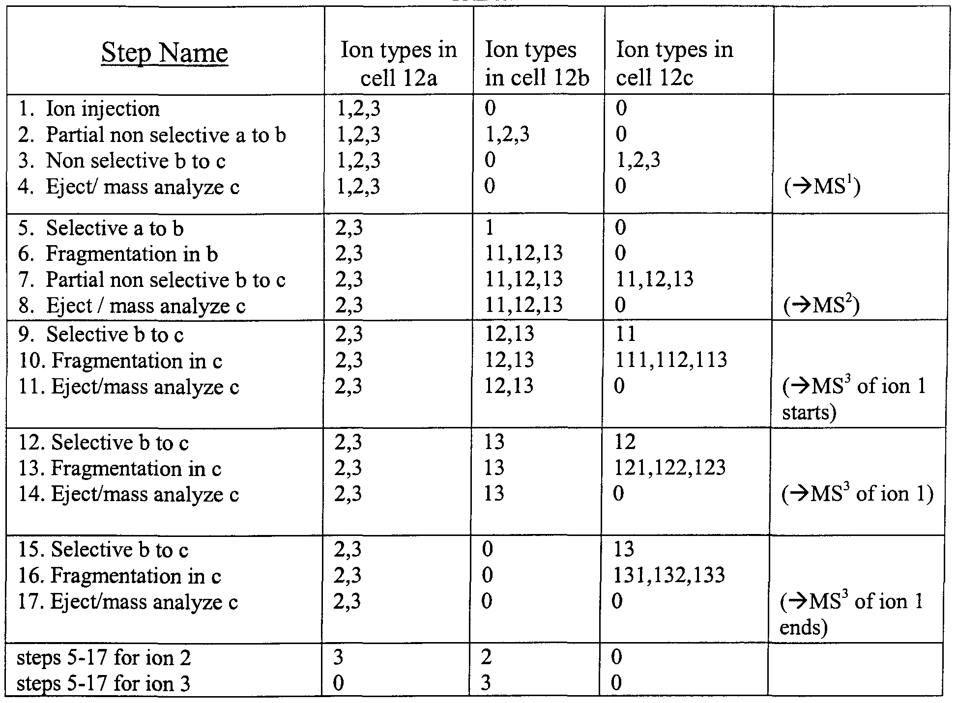
TABLE 1
Table 1 shows an example of ion manipulation and storage in the array of Fig. 1 for a complete MS3 analysis of a single ion species from an ion packet composed of ion species 1, 2 and 3. The table explicitly illustrates only the steps for the full MS3 analysis of ion 1; the analysis of 2 and 3 would be identical except for different excitation frequencies (corresponding to different m/z values) used for selective transfer and fragmentation. The mixture of ions 1, 2, 3 is initially injected into the first storing cell 12a. In the second step part of the ion packet is non-selectively transferred to the next cell 12b. In the third step, the ion mixture is then non-selectively transferred to the last cell 12c, and in the fourth step the ion content of the last cell is ejected and mass analyzed, providing information corresponding to an MS1 analysis. The details of such mass analysis will be described subsequently. The cycle of the first four steps permits determination of the masses of primary ions. In step 5, ion 1 of a predetermined mass is selectively transferred from cell 12 a to cell 12b. In step 6, the ion species 1 in 12b is fragmented, for example, by applying a selective AC excitation. Alternatively, steps 5 and 6 can be combined if ions are accelerated by a sufficient DC offset between cells 12a and 12b. The masses of ion fragments are characterized in steps 7 and 8. The small portion of ion content of the cell 12b is moved
to the last cell 12c and subsequently mass analyzed, thus providing information corresponding to an MS2 analysis. The MS3 analysis starts with steps 9, 10 and 1 1 m which the fragment 11 m cell 12b is mass-selectively transferred to cell 12c where it is dissociated and the fragments 111, 112 and 113 are ejected and mass analyzed. Then in steps 12, 13 and 14, the fragment 12 is subjected to an MS3 analysis by mass-selective transfer from cell 12b to 12c where it is dissociated and the fragments 121, 122 and 123 are ejected and mass analyzed. Then in steps 15, 16 and 17, the fragment 13 m cell 12b is mass- selectively transferred to cell 12c where it is dissociated and the fragments 131, 132 and 133 are ejected and mass analyzed, thus completing the MS3 analysis of ion 1. It is likely that ions of the sampled m/z value will not be removed completely in the steps of selective sampling. The ions remaining m cell 12b can then be ejected and mass analyzed in order to improve the signal to noise ratio of the MS2 analysis previously conducted in step 8. The same protocol could then be applied to the remainder of ion species 1 in trap 12a or ion species 2 and 3 in 12a. The protocol described allows unambiguous identification of the m/z of the parent ion of a fragment even if all the ions of a particular m/z ratio are not selectively transferred. It remains important, however, that non-selective transfer, e.g., in the ejection for mass analysis, be complete.
Sampling a small portion of any trappmg cell's content into an external mass spectrometer will allow the use of economic data dependent algoπthms, m which information about fragment masses is known before the subsequent steps of selective ion sampling. For example, the ion fragments identified in the MS2 spectrum of the initial samplings of the parent ion could be flagged for MS3 analysis in subsequent samplings. In each of the subsequent samplings, after the known MS2 fragments are transferred to 12c and MS3 analyzed, residual MS2 fragments m 12b can be ejected and mass measured to improve the MS2 dynamic range. At a later point, the MS2 ion fragments identified after multiple samplings of ions of a given species could then be added to the MS3 list.
The branched MS/MS analysis can be used to follow all the channels of fragmentation of a particular ion using all of the ion mateπal initially injected into the trap to thereby improve sensitivity and selectivity of MS" analysis, or, if desired, the first ion sampled can be fragmented and mass analyzed and then the second ion (still resident m the first stonng cell) can likewise be sampled and analyzed, and so on and so forth. The versatility and power of the branched MS/MS method can thus be appreciated.
The embodiment of Fig. 1 is thus configured and operates to select particular parent ιon(s) of interest, to fragment the ions of interest, to detect the resultant product ions, and then repeat the
selection/fragmentation/detection processes a number of times. This technique of sequential dissociation is referred to in the art as MS" analysis. Unlike prior techniques, the unique "select and store" feature of the present invention enables a highly sensitive MS" method to be carried out in which the isolation/fragmentation sequence for a particular sampled ion may be extended by additional steps to obtain more structural information of sampled ions or in which individual constituents of a mixture may be efficiently and cost effectively analyzed. The advantages of MS" techniques, especially the additional information available to the analyst, and the various strategies that may be employed in interpreting results have been described in the literature. For example, dissociation of an ion fragment can produce new types of product ions that may not be observable in single-stage MS (metastable or CID) analyses. In addition, specific structural features such as linkage types may be identified by the hierarchy of ion fragmentation, particularly when such identification is difficult to achieve by measurement of mass alone (e.g., for isobaric ion fragments).
While the particular strategy to be employed depends on the type of sample being analyzed, techniques for analyzing data and arriving at useful results are within the skill of the ordinary artisan. Guidance may also be had by referring to recent publications in this field. For example, Ngoka and Gross in J Am Soc Mass Spectrom 1999, 10, 732-746 describe strategies for MS" analysis of cyclic peptides. Lin and Glish in Analytical Chemistry, Vol 70, No. 24, December 15, 1998 disclose techniques for C-terminal peptide sequencing via multistage (MSn ) mass spectrometry. Also, the role of MS" in the analysis of carbohydrates, and the strategies for interpreting results, is described by Solouki et al. in Analytical Chemistry, Vol. 70, No. 5, March 1, 1998. Each of these foregoing references is incorporated by reference herein.
Referring to Fig 3 A, one preferred embodiment of an MS" mass spectrometer 30 of the present invention is as a linear array of harmonic linear traps (HLTs). The embodiment includes a pulsed ion source 31, a linear array of HLT ion traps, composed of a plurality of communicating open parallelepiped cells 32, a vacuum housing 33, a set of power supplies 34 and an external mass spectrometer 35. The parallelepiped cells of the HLT array are composed of separate rectangular electrodes oriented in ZX and ZY planes with no plates in the XY plane, i.e. the Z-faces are omitted. As shown the guarding cells have a greater length along the z axis than the storing cells. This configuration optimizes performance relative to the cubic cell shown in Fig. 1 , for example, by creating a dipolar field for z excitation with a reduced radial component and by increasing the z oscillation frequency for a given DC voltage on the guard cell. Both factors contribute to higher resolution in mass-selective
transfer. The first trap of the array is in communication with the pulsed ion source 31 and the last trap with the mass spectrometer 35. The HLT array is enclosed in the vacuum housing 33 at an intermediate or variable vacuum, separated from the vacuum chamber of ion source 31 and mass spectrometer 35. The pressure in the HLT array is sustained by a vacuum pump and gas inlet (not shown). Power supplies of the set 34 are electrically connected to individual square electrodes of the array. A single frequency RF voltage is applied in phase to the top and bottom plates (X plates) of each cell and π out of phase to the front and back plates (Y plates) of each cell with an RF frequency in the range from 300 kHz to 3 MHz and an amplitude of 1 to 10 kV. The same DC voltage is applied to the four electrodes of an individual cell. The DC voltage is separately established for each cell and is varied during the ion transfer steps. Typical DC voltages are in the range from 10 to 300V. The AC voltage is applied between pairs of adjacent cells with frequencies in the range of 10 KHz to 1 MHz and amplitude of 1 to 30V. The voltage sources are decoupled from one another using capacitors, floated transformers and inductive coils and similar schemes well known in the art (see Fig. 3C).
As further shown in Fig. 3B, the HLT array can serve as an interface between either electrospray or MALDI ionization source and a high resolution mass spectrometer such as a TOF, FT- ICR or Paul trap mass specfrometer.
The configuration of each HLT has the novel property of trapping ions while allowing (locally) harmonic oscillations in the axial (z) direction. The RF voltage creates an axially uniform RF field that provides radial confinement of ions. The DC potentials are applied to all four electrodes of each individual cell. As seen from the potential energy diagram UDC in Fig. 3A, the cells with a local minimum of DC potential are the storing cells (denoted as SI, S2) while cells with a local maximum of DC potential are the guarding cells (denoted as GO, Gl, G2). Both cell triplets (GO, SI, Gl) and (Gl, S2, G2) create HLTs, hence Fig. 3 A illustrates an array of two HLTs. Because of colhsional cooling in rarefied gas the ions lose their kinetic energy and are confined to the center of the storing cells, as long as the ion's internal energy does not exceed the fragmentation threshold and the kinetic energy of the height of the DC barrier. In the case of using a slowly pulsing ESI source, with ~ 1 sec switching time, the storing capacity of the first cell may be insufficient. Then, a long multipole guide at intermediate pressure is used as a buffer. Non-selective transport of ions between cells is accomplished by reducing the DC potential of the target (acceptor) cell below the potential of the donor cells and by lowering the potential of the guarding cells in-between. The cumulative gradient of DC fields applied to the different cells could be used for continuous flow of ions through the HLT array.
The HLT array device of this embodiment provides highly sensitive MS" analysis, using the strategy of branched MS/MS analysis. The individual steps of selective and non-selective transfer, fragmentation and colhsional damping are described below.
Selective sampling of ions of interest is done m a two-step process In a first step a resonant AC signal is applied in a dipolar mode between a trapping cell and a guard cell on either side of the trapping cell This is used to excite axial oscillations of the ions of interest In the HLT the axial (z) component of the trapping field is a pure electrostatic field with a parabolic profile near the oπgm. Thus, the peπod of the ion's axial oscillations near the ongin is proportional to the square root of mass/charge ratio, so that the frequency of the applied AC signal directly corresponds to the mass/charge ratio of selectively excited ions. In the second step the potential of the guard cell immediately downstream is rapidly lowered after a predetermined number of excitation cycles. The number of cycles depends on the efficiency of resonant excitation. In one example, the number of cycles was estimated by numencal simulation withm realistic instrument geometry and operating parameters, and found to be about 100 z-oscillation cycles over a peπod of about 2 ms. This estimation can be later refined as part of an instrument tuning procedure. Only the resonantly excited ions have the proper z oscillation amplitude and phase to cross over the lowered barπer and into the next stonng cell. Trapping of ions in the acceptor cell is assisted either by collisions with gas at a higher gas pressure or by dynamic trapping, i.e., a rapid reassertion of the guard cell potential after the selected ions have crossed the barπer.
In one preferred embodiment the dipolar AC is not a single frequency waveform but a time dependent frequency waveform (such as a nonlinear chirp). The electrostatic axial field is parabolic only in a neighborhood of the oπgm and as the ions are excited away from the ongm by the dipolar field their z oscillation resonance frequency changes with amplitude. Applying a near harmonic waveform that shifts frequency in concert with the anharmonic oscillations of the dπven ions improves the m/z selectivity of the ion transfer. The non-selective transfer is made by loweπng the DC barner between adjacent cells and by setting the DC potential of the ion donor cell higher than the DC potential of the ion acceptor cell.
In one preferred embodiment the steps of ion fragmentation are also implemented by dipolar excitation of the axial (z) coordinate, only without the loweπng of the guard cell potential. The axial ion motion remains strongly confined by the static DC field irrespective of the m/z shift going from the parent ion to the fragment ions. The radial coordinates are governed by Mathieu stability and the ion
fragments must have stable trajectones to be trapped. However, m contrast to the Paul trap, the Mathieu-governed (radial) coordinates are not directly dnven and their amplitude remains small.
In one preferred embodiment fragmentation is accomplished by raising the DC potential difference between donor and acceptor cells above a threshold level of- 40V per 1 kD of ions mass. The sampled ions are accelerated between cells and expenence energetic collisions with gas molecules in the acceptor cell. The kinetic energy is transferred into internal energy and ions are trapped and produce fragment ions that have even lower kinetic energy and are trapped as well.
Each step of transfer or fragmentation is usually followed by a colhsional damping of fragment ions. Ion damping, i.e., confinement near the ion trap ongm is necessary for the subsequent step of selective sampling. In one mode of operation the gas pressure m the ion trap array is held constant at the 10"5 torr level. Such pressure is sufficiently low to avoid colhsional damping at a sampling step, and takes about 1ms in time. However, colhsional cooling at such a low gas pressure would take at least 10 to 100-fold longer time, which would slow down a multistep branched analysis. For example, a 50 step analysis would take up to 5 sec. To accelerate the MSπ analysis the gas can be introduced in short pulses, such that the gas pressure is higher dunng ion dampening and the gas is evacuated dunng selective sampling steps. The gas pulses can be also introduced dunng the ion fragmentation step without affecting fragmentation process.
When higher resolution of selective sampling is desired, an array of traps can be composed using alternative types of traps, such as RF-only quadrupole traps (Fig. 4A) and Paul traps (Fig. 4B).
Referring to Fig. 4A, the ion trap array is composed of RF-only quadrupole traps. Each trap includes a stonng cell made out of 4 cylindrical rods (quadrupole) surrounded by two plate electrodes. The plates are shared between adjacent traps. A higher DC voltage on the guarding plates provides a static barπer, which normally retains ions within the stonng quadrupole cells. The RF signal is applied between pairs of quadrupole rods creating a quadrupolar field. The AC signal is applied between quadrupole rods either m quadrupolar or a dipolar mode.
In operation, the steps of ion non-selective transfer, fragmentation and dampening are made exactly as was descnbed above for HLT traps. The step of selective ion transfer is earned out in a way unique for RF-only quadrupole traps. The pnncipal difference is defined by the type of field at the
boundaries of the RF-only quadrupole. Contrary to HLT, the RF field is no longer uniform along the z- axis. The RF field diminishes in the vicinity of the guarding plates. As a result, the gradient of the RF field forces certain ions out of the quadrupole, while the DC barrier retains the other ions within the quadrupole trap. The gradient of the RF and AC fields causes coupling between radial and axial motion. Ions of interest are selectively excited either by the RF field or by an additional AC signal, gain kinetic energy, penetrate through the DC barrier and get transferred to an adjacent frap. Selective ejection out of RF-only quadrupole is described in experimental studies of Hager, J., reported in Rapid Communications in Mass Spectrometry, 13, 740-748 (1999) whose disclosure is hereby incorporated by reference. The device is known to produce a low energy ion beam and provide high-mass resolution of ion ejection. Typically, the RF and AC amplitudes are ramped up and ions are ejected in sequence of m/z values, with light ions being ejected first. This limits flexibility in choosing the order of ion selective sampling, but still allows multiple strategies of the branched MS" analysis. A higher flexibility is achieved by applying a frequency adjusted AC signal. Ions of specific m/z are selectively excited radially and gain a higher kinetic energy. Due to the above mentioned coupling between radial and axial motions, the axial kinetic energy of ions is increased and ions get transferred through the DC barrier.
Since resolution of ion selection is improved compared to open cubic cells, it is expected that the specificity of the MS" result and information content could be high even without an external mass spectrometer. The last cell itself is used for mass analysis. A separate RF voltage can be applied to the last cell for a rapid resonant ejection of ions onto a time resolving detector, similar to the RF-only quadrupole or the Paul ion trap techniques. The separate RF voltage can also improve the resolution of selective sampling. Since all the described processes are occurring sequentially in time, an "analytical" grade RF power supply could be connected to the cell requiring mass analysis, while the rest of the cells are connected to a storing RF power supply.
Referring to Fig 4B, one preferred embodiment of a tandem mass spectrometer of the present invention is as a linear array of Paul traps. As was described previously, conventional Paul fraps are capable of trapping and collisionally cooling ions, selectively sampling and fragmenting ions moving ions between cells and ejecting them into an external detector or mass specfrometer. By using an array of traps the use of a Paul trap is extended for selective fransfer between traps. Thus, this type of array can also be used in practicing the present method of sample and store MSn analysis with storage of intermediate ions and analysis of fragmentation channels.
In order to create an array of Paul traps the conventional geometry of curved electrodes of the Paul trap is altered. Here the traps are realized by a cylinder with two coaxial flat rings, serving as cap electrodes, as has been described by Kornienko et al. in Rapid Commun. Mass Spectrom. 13, 50-53 (1999) whose disclosure is hereby incorporated by reference. Two ring electrodes could be used to further approximate the cylinder as has been described by Ji, Davenport and Enke. in J Am Soc Mass Spectrom 1996 7, 1009-1017 whose disclosure is hereby incorporated by reference. An RF signal is applied to the cylinder while the DC potential is applied to the flat rings. A higher frequency and lower amplitude RF field signal is used to facilitate a sufficiently soft ion ejection/ sampling. In this embodiment the flat ring cap electrodes serve as guard cells and the barrier between the Paul traps is an effective potential (often described as a pseudopotential well depth) and not simply an electrostatic barrier reflecting the DC applied to the cap. These traps have an open design, compared to conventional Paul traps that facilitates ion exchange between cells. Paul traps are known to provide storing and colhsional cooling of ions. Ions can be selectively moved between fraps by dipolar excitation (AC) at the resonant frequency of ion z motion in the trap ("resonant ejection"). Here the dipolar AC is applied to the coaxial flat rings surrounding the cylindrical electrode.
The external mass spectrometer used with the embodiments described can be any kind of high resolution MS with parallel ions detection, including high resolution Paul ion trap, FT-ICR, TOF MS and TOF-MS with orthogonal injection (o-TOF MS). The TOF MS is a particularly attractive detector, providing instant detection of all ion fragments and thus enabling rapid characterization of multiple fragmentation channels in the array.
Referring to Figs. 5A-C, ions produced in the trap array are injected into an external TOF MS using the following alternative schemes: a) Ions are injected into the o-TOFMS via a multipole ion guide with colhsional cooling (Fig.
5A), b) Ions are collisionally cooled in a specialized trapping cell and then ions are pulsed injected into synchronously pulsing acceleration stage of the o-TOFMS (Fig. 5B), c) Ions are collisionally cooled in the last cell of the linear array of traps at a low gas pressure (below 1 mtorr) and then ions are pulsed out of the cell directly into an axial TOF MS (Fig. 5C).
Scheme (a) utilizes a quadrupole ion guide to relax kinetic and internal energy of ions ejected out of the trap array and to confine the beam to the axis. Currently all commercial o-TOF MS utilize an
ion guide with colhsional cooling The quadrupole ion guide is known to form a perfect ion beam for the consequent analysis in o-TOF MS. The disadvantage of the scheme is a moderate efficiency (10- 20%) in utilizing a continuous beam The problem is known in the art as a duty-cycle losses in orthogonal TOF. Only 10-20% of ions are inside the orthogonal pulsing region at the time of the pulse, the rest of the ion beam is not used.
Scheme (b) utilizes a specialized, generally asymmetric HLT instead of the quadrupole ion guide. Using colhsional cooling the ion beam's kinetic energy is decreased and is confined to the axis of the last cell. The packet of ions is pulsed injected into the orthogonal acceleration stage of o-TOF MS Here the objective is ion packet compression and optimal fransfer to the orthogonal acceleration stage of o-TOF MS. The ion packet is shorter than the orthogonal pulsing region (typically 1 to 2") and with proper synchronization the entire ion beam can be used in the o-TOF MS. The scheme improves sensitivity of the method and allows keeping the HLT and TOF MS in separate differentially pumped chambers. While the optimum pressure m the trap is around 1 mtorr, the gas pressure in the TOF analyzer has to be in a low 10"6 torr range or lower.
Scheme (c) eliminates an extra step, compared to scheme (b). Ions are directly pulsed out of the last trapping stage of the linear array of traps after colhsional cooling. A preferred method involves pulsing out of a planar segmented trap (Fig. 5C) at a low gas pressure. The scheme ensures desired initial conditions of the beam at the time of the pulse In one particular instance the gas is introduced by a pulsed valve at the time of the fragmentation and cooling steps, and the gas is pumped down at the time the TOF pulse is applied. In another particular case the ions are injected into the final cell located in the subsequent pumping stage and operated at a lower, sub-milhtorr gas pressure.
Having descnbed preferred embodiments and some examples of combining useful elements, it will now become apparent of skilled in the art that other embodiments incorporating the concepts may be used. It is felt, therefore, that this embodiment should not be limited to disclosed embodiments, but rather should be limited only by the spirit and the scope of the following claims.