WO2001071277A1 - Electrostatically-actuated tunable optical components using entropic materials - Google Patents
Electrostatically-actuated tunable optical components using entropic materials Download PDFInfo
- Publication number
- WO2001071277A1 WO2001071277A1 PCT/US2001/008893 US0108893W WO0171277A1 WO 2001071277 A1 WO2001071277 A1 WO 2001071277A1 US 0108893 W US0108893 W US 0108893W WO 0171277 A1 WO0171277 A1 WO 0171277A1
- Authority
- WO
- WIPO (PCT)
- Prior art keywords
- deformation
- perot interferometer
- tunable
- compliant member
- movable
- Prior art date
Links
Classifications
-
- G—PHYSICS
- G01—MEASURING; TESTING
- G01B—MEASURING LENGTH, THICKNESS OR SIMILAR LINEAR DIMENSIONS; MEASURING ANGLES; MEASURING AREAS; MEASURING IRREGULARITIES OF SURFACES OR CONTOURS
- G01B9/00—Measuring instruments characterised by the use of optical techniques
- G01B9/02—Interferometers
- G01B9/0209—Low-coherence interferometers
-
- G—PHYSICS
- G02—OPTICS
- G02B—OPTICAL ELEMENTS, SYSTEMS OR APPARATUS
- G02B26/00—Optical devices or arrangements for the control of light using movable or deformable optical elements
- G02B26/001—Optical devices or arrangements for the control of light using movable or deformable optical elements based on interference in an adjustable optical cavity
-
- G—PHYSICS
- G02—OPTICS
- G02B—OPTICAL ELEMENTS, SYSTEMS OR APPARATUS
- G02B26/00—Optical devices or arrangements for the control of light using movable or deformable optical elements
- G02B26/02—Optical devices or arrangements for the control of light using movable or deformable optical elements for controlling the intensity of light
-
- G—PHYSICS
- G01—MEASURING; TESTING
- G01B—MEASURING LENGTH, THICKNESS OR SIMILAR LINEAR DIMENSIONS; MEASURING ANGLES; MEASURING AREAS; MEASURING IRREGULARITIES OF SURFACES OR CONTOURS
- G01B2290/00—Aspects of interferometers not specifically covered by any group under G01B9/02
- G01B2290/25—Fabry-Perot in interferometer, e.g. etalon, cavity
Definitions
- This invention relates to tunable optical components .
- tunable optical components such as tunable filters, tunable laser sources, tunable dispersion compensators (both chromatic and polarization mode) tunable add/drop multiplexers, etc.
- MEMS devices are a promising new class of tunable optical components . These devices generally comprise an array of small (ca. micron sized) moving parts, which are manipulated into desired configurations, to actuate an optical member. For instance, an array of micromirrors can be manipulated to create an optical cross connect switch, a pair of parallel mirrors can be manipulated to create a tunable Fabry-Perot Interferometer, etc.
- MEMS devices are constructed with silicon, metallic or glassy hinges, which anchor a moving, part (e.g. a micromirror) to a substrate, which typically contains a control electrode.
- a command signal in the form of a voltage is applied between the electrode and the moving part, the moving part moves against the restoring force exerted by the hinge.
- Use of these silicon/glassy/metallic materials for hinges creates engineering hurdles, which severely limits the design space of the MEMS device.
- these limitations are accepted, or circumvented with a series of electrodes together with a feedback control loop that maintains tight control over the position of the moving parts.
- These limitations include the inherent stiffness of such materials, the limited linear elastic range of such materials and the complexity, hence expense of the precision lithography associated with machining such materials.
- the present invention provides a cost-effective approach for tunable optical components with an enhanced range of motion.
- a cost- effective broadband tunable Fabry-Perot interferometer that includes a pair of mirrored surfaces separated by an initial optical path length corresponding to the desired free spectral range.
- One of the mirrors is fixed while the other moves against the restoring force exerted by a compliant member.
- Tunability is afforded by creating field lines that exert a force by, for example, electrostatic or magnetic means that deforms the compliant member. When the force is removed, the energy stored in the compliant member restores the mirror to the initial separation.
- the compliant member is formed of an entropic, rather than an enthalpic material, with a variety of geometries including compression, tension, shear and combinations thereof .
- Entropic materials afford four key advantages over enthalpic materials (e.g. silicon, metals, glasses), pertaining to device response and positional/angular stability.
- Entropic materials e.g. long chain homopolymers , block copolymers, elastomers, aerogels etc.
- Entropic plateau region characterized by an elastic modulus that is ca. 5MPa or less, and is independent of frequency and strain level over a wide range of frequencies and strain levels .
- Enthalpic materials have an elastic modulus that is ca. 1 GPa or more, and is independent of frequency only for very small strain levels. Hence, entropic materials are far more compliant .
- Entropic materials have a much higher elastic limit (more than ca. 100% strain vs. less than ca. 1% strain for enthalpic materials) and thus avoid plastic deformation during actuation. This greatly enhances the achievable tuning range .
- Entropic materials are incompressible ⁇ the energy cost for volume deformation is nearly infinite, when compared to the energy cost for linear and shear deformation. This compares with enthalpic materials wherein the energy cost for volume and linear deformations are comparable. This large difference in the energy cost of deformation possessed by entropic materials can be exploited to great advantage in the design of tunable optical components.
- the energy cost for angular misalignment can become much higher than the energy cost for tuning with an entropic compliant member material, thus the device can be intrinsically more resistant to misalignment during tuning that an equivalent design that uses enthalpic materials .
- Entropic materials have a normal stress behavior: when they are shear deformed, they exert a so called normal stress perpendicular to the direction of shearing, in addition to the shear stress directly resulting from the shear strain. This behavior can be used to further enhance stability with specific compliant member geometries.
- enthalpic materials display a negligible normal stress behavior, and thus the normal stress behavior cannot be exploited for enhanced stabilities with enthalpic restoring layer materials .
- FIGS, la-lc are, respectively, command signal, power spectrum and Young's modulus plots that together illustrate the required linear elastic properties for tunable optical components;
- FIG. 2 is a log-log plot Young's modulus (E) versus frequency ( ⁇ ) for enthalpic materials;
- FIGS. 3a-3b are, respectively, plots of a representative interatomic potential for a two-atom system and the force-displacement curve felt by individual atoms;
- FIG. 4 is an illustration of a long chain entropic material and three deformation modes
- FIG. 5 is a log-log plot of modulus (G) versus frequency ( ⁇ ) for non-crystalline materials with various chain lengths;
- FIG. 6 is an energy profile of a device illustrating the increase in device energy for positional and angular misalignment ;
- FIGS. 7a-7b are, respectively, perspective and section views illustrating compressive deformation of an elastomeric layer
- FIGS. 8a-8b are, respectively, illustrations of the increase in the restoring normal stress if a shear type device is subject to angular misalignment and the normal stress ( ⁇ nn ) acting on a unit volume element of an entropic material subjected to shear deformation ( ⁇ 12 ) ;
- FIGS. 9a-9e illustrate different compliant member geometries, including compressive, tension, diaphragm, shear and quasi-shear, in accordance with the present invention
- FIG. 10a and 10b illustrate, respectively, electrostatic and electromagnetic actuation mechanisms for use with any of the device geometries, in accordance with the present invention
- FIG. 11 is a schematic illustration of a conventional tunable Fabry-Perot interferometer
- FIGS. 13a-13e illustrate different compliant member geometries for use with a tunable Fabry-Perot interferometer, including compressive, tension, diaphragm, shear and quasi-shear, in accordance with the present invention.
- the present invention provides a cost-effective solution for tunable optical components with an enhanced range of motion.
- the compliant member must display linear-elastic behavior over a wide range of frequencies and over the entire deformation range at low actuation forces.
- the entropic material provides such behavior .
- the compliant member must display positional and angular stability to within a tight tolerance.
- the entropic material provides a very steep energy profile that enhances stability for a given device compliance.
- the energy cost of misalignment becomes significant compared to the energy cost of deformation.
- the energy cost for misalignment remains comparable to the energy cost for tuning irrespective of the device geometry: hence conventional devices are less stable than the present invention.
- Entropic materials also provide a normal stress component, which can further enhance stability in certain member geometries.
- any solution must avoid expensive materials, and high precision manufacturing operations such as precision lithography with its high capital investment, provide high yields, limit the complexity of any external control circuitry and minimize recalibration requirements (manual or automatic) .
- entropic materials exhibit much lower Young's modulus than enthalpic materials
- the compliant member can be much thicker and generally less precise than enthalpic materials of equivalent stiffness without sacrificing performance.
- spin coating and curing entropic materials versus the expensive vacuum based deposition technologies used in standard MEMS processes for enthalpic materials .
- the larger linear range and enhanced stability of entropic materials vis-a-vis enthalpic materials reduces the need for external control and frequent recalibration.
- the compliant member must display linear-elastic behavior over a wide range of frequencies, and over the entire deformation range. Failure to maintain a linear response can cause numerous problems including varying response to drive signals, positional and angular instability, the need to include expensive electronic control and frequent recalibration. As depicted in Figures la-lc, a triangular command signal
- (31) has a power spectrum that is significant in magnitude over several decades in frequency (32) .
- the device is characterized by its stiffness. If the device stiffness (E) (33) changes with frequency, then the shape of the device response (34) significantly differs from the shape of the command signal.
- This relatively simple illustration (which ignores viscous effects) outlines the requirement for an elastic compliant material that is absent of any viscous effects. In other words, any change in the material's Young's modulus (either with deformation frequency/time scale, or with deformation strain level) will produce a non-linear response (here, non-linearity refers to a discrepancy between the shape of the device response and the command signal) .
- the Young's modulus can be associated with the energy cost of deforming the compliant member. If the response is complex and time dependent, then the modulus is best described as either being time dependent G t , or being frequency dependent, and comprising an elastic part (G' ⁇ ) and a viscous part (G" ⁇ ) .
- the overall modulus originates from several modes,
- Equation 1 g ⁇ is the initial modulus contribution of the i th mode, and ⁇ t is the corresponding relaxation time. From a molecular viewpoint, examples of a mode include bond stretching, rotation, vibration, and bending.
- enthalpic materials such as crystalline silicon exhibit variable Young's modulus, hence non-linear behavior, for even the smallest deformations .
- Figure 2 summarizes the frequency dependent elastic modulus for crystalline solids and non- crystalline glasses and liquids.
- the modulus is ca. 1 GPa or higher above the dynamic glass transition, and decreases rapidly as the frequency decreases below the dynamic glass transition.
- Crystalline solids 71 do not display a dynamic glass transition, and the modulus is relatively independent of frequency for small strain levels . However, as the strain levels increase 72, 73, the modulus decreases with decreasing frequency. This behavior is generic to all enthalpic materials, and can be understood with a simplistic atomic model for the macroscopic modulus, as shown in Figure 3.
- the interatomic potential 75 describes the potential energy of a two-atom system as a function of the distance between the two atoms.
- the two body interatomic potential can be used to illustrate the enthalpic modulus of crystalline and glassy materials.
- the atoms rest in energy minimum positions; when an external strain is applied, the potential energy of the atom climbs up the interatomic potential .
- the force 76 felt by the atom is the slope of the interatomic potential, and is depicted in Figure 3b.
- the atomic rest position 77 corresponds to the separation where the force is zero; as the atoms are pulled apart, the force increases, corresponding to the slope of the interatomic potential .
- the macroscopic enthalpic material comprises many such two-atom and many-atom subsystems, but the initial slope of all such subsystems is about the same, and corresponds to an overall modulus of ca . 1 GPa or more.
- the g for all modes is ca. 1 GPa or more, and the overall modulus appears to be independent of deformation frequency.
- the energy cost for • deformation in entropic materials does not originate in changes in the interatomic distances, but in available atomic configurations .
- the overall modulus of entropic materials can also be frequency independent (as discussed below) , but at much lower values.
- Figure 4 depicts a long polymeric strand 80 in which several atoms 82 along the backbone are covalently linked together. Under normal conditions (i.e. in the undistorted melt or dilute solution state) , the mean square end-to-end distance of the strand is given by
- Equation 2 n is the number of backbone bonds in the chain, £ is the length of one backbone bond, ⁇ is the bond angle; and C x and ⁇ are two other factors. Equation 3
- n is large (ca. 100 or more) , then the root mean
- entropic materials are best described by random coils of long chains comprising several hundred backbone bonds. If the two ends are fixed, then the random coil can adopt several configurations within the two constrained end points.
- the root mean square end-to-end distance is increased, but remains small compared to the chain contour length. Within this altered state, the chain can still adopt several possible configurations, but the number of available configurations decreases from the unaltered state. This decrease in the number of available configurations results in an increase in the entropic energy of the system ⁇ this is the source of the energy cost of deformation for entropic materials. If n is large, then the root mean square end-to-end distance remains negligible compared to the contour length of the chain.
- the deformation process remains linear (stress is linear with strain) for large strain limits (ca. 100% or more) ⁇ it is only when the r.m.s. end-to-end distance becomes comparable to the contour length that the deformation process becomes non-linear.
- the modulus of entropic materials is several orders of magnitude lower than that of enthalpic materials (ca. less than 1 MPa compared to greater than 1 GPa) .
- the deformation process comprises several modes, the first few are depicted in Figure .
- the different deformation modes resemble the vibration modes of a string, with the higher order modes corresponding to deformation at shorter length scales.
- the relaxation time of a mode increases with increasing mode length scale, and if the length scale of a mode is greater than ca. 100 backbone bonds, then the mode conforms to entropic elasticity (i.e. the enthalpic energy cost of deformation within that mode is negligible) .
- entropic elasticity i.e. the enthalpic energy cost of deformation within that mode is negligible
- the first few modes conform to entropic elasticity.
- the modulus is dominated by the initial modulus of the first few modes, and becomes independent of dynamic frequency or time of actuation.
- the long chain polymer can be further reacted into different topologies (e.g. a crosslinked network as in an elastomer, which can be further modified into an aerogel by incorporating air bubbles) .
- entropic materials such as elastomers, aerogels or long chained polymers exhibit a broad entropic plateau region (90) below the dynamic glass transition 91 as shown in Figure 5.
- the dynamic glass transition moves to higher frequencies as the temperature is raised.
- the entropic plateau region 90 extends over several frequency decades and an extremely wide range of deformation in which the Young's modulus is essentially constant.
- the essential device requirement is that the upper corner frequency 92 is at least one order of magnitude larger than the device actuation rate, and the lower corner frequency 93 be at least one order of magnitude smaller than the device recalibration frequency.
- the upper corner frequency of the plateau region is the lower edge of the dynamic glass transition.
- Entropic materials are incompressible, with a near infinite bulk modulus . This comes about because the Poisson's ratio (v) is ca. 0.5.
- the Bulk modulus is nearly infinite, even though the Elastic modulus is ca. 0.1 to 1 MPa. This compares to the situation in solids and glasses wherein the Poisson's ratio is ca. 0.33, and the bulk modulus K is ca. 3 times greater than the elastic modulus. From a molecular viewpoint, the infinite bulk modulus implies a near infinite energy cost for isothermal volume changes in the entropic material. This compares with solids and glasses wherein the energy cost for volume and linear deformations are comparable.
- ⁇ is the viscosity associated with the flow process
- V is a characteristic velocity associated with the flow
- d is the thickness of the elastomer layer
- L is the lateral dimension
- this force is associated with a pressure gradient between the center and the edges of the elastomer layer.
- Equation 3 is an approximation that only serves to illustrate the general scaling behavior. With this approximation, it can be seen that the response time varies with the viscosity, the square of the elastomer lateral dimension, and the inverse of the 3 rd power of the elastomer thickness.
- the response time will always be infinite for a perfect elastomeric network.
- the viscosity in real elastomers is a finite number, because the degree of crosslinking is always less than 100% (>90% often being considered " fully crosslinked” ) .
- Incorporating network defects and/or small dopant molecules within the elastomer and/or modifying the network itself to facilitate flow can further lower the viscosity.
- the network can be modified by, for instance, swelling the elastomer network with dopant molecules (e.g. toluene will swell a silicone based elastomer) . This lowering of the viscosity enables devices in which the entropic compliant member is compressed for the moveable optical element motion.
- the viscosity is associated with center of mass motions (i.e. the fundamental mode depicted in Figure 4) of small (er) unreacted polymer strands in the elastomer and other dopant molecules of finite molecular weight. These smaller molecules flow in the matrix of the elastomer network (strands of the network cannot undergo center of mass motion) .
- center of mass motion is characterized by the corresponding modulus falling rapidly below 1 MPa as shown in Figure 5.
- the characteristic frequency of center of mass motion decreases as the chain length increases. This frequency (97) can be very high if the chain length is very small. This time constant follows from the inherent viscosity of the dopant molecules, and the size of the molecular channels through which they must flow. Under these conditions, both the tensile and the compressive devices become viable.
- the flow process remains a dissipative energy loss mechanism ⁇ the energy required for flow is lost from the system, and must be minimized in comparison to the energy associated with elastomer deformation. If the total energy associated with device operation is dominated by the dissipative term, then the device response becomes time dependent (i.e. the device response becomes dependent on its loading history) , and the dissipated energy also serves to reduce the device lifetime.
- the tuning operation does not require any volume change in the entropic compliant member. For instance, if the motion of the moveable optical element requires shear deformation of the entropic compliant member, then there is no volume change requirement on the compliant member. In a diaphragm type device, optical element motion requires a tensile/compressive loading on the compliant member. Under these conditions, the net volume change is small, and the length scale over which the volume must change (across the thin diaphragm layer) is also small ⁇ viscous flow effects become negligible for these devices as well. In these cases, the material's response time is determined by the elastic plateau behavior of the entropic compliant member only.
- the compliant member hence the movable optical element, must both be positionally and angularly stable to provide repeatable performance.
- a stable device results when the potential energy of the device increases sharply with any deviation from the desired angle and position: devices in which this potential energy increase is minimal will be unstable.
- the potential energy content of the device is approximately proportional to kT (k is the Boltzmann's constant, and T is the absolute temperature) .
- the device possesses entropic energy approximately proportional to the width of the configuration space explored by it.
- the angle and position of the moveable optical element will explore the configuration space wherein the increase in device energy is proportional to its energy content (kT and entropic energy) .
- the corresponding misalignment and positional inaccuracy must be within the specifications discussed previously.
- the steeper energy profile 111 is preferred over the shallower energy profiles 112 and 113.
- Entropic materials can afford better angular stability as best illustrated by considering a shear type device illustrated in Figure 8a wherein the moveable optical element moves against a shear stress exerted by the compliant member. Deviations from the desired angular position are accompanied by an energy cost of distorting the compliant member ⁇ this energy cost includes the energy for volume deformation in the compliant member 162. For enthalpic compliant members, the energy cost for shear and bulk deformations are comparable: thus, the energy costs for angular misalignment and optical element motion are comparable.
- the bulk modulus is several orders of magnitude greater than the shear modulus : thus the energy cost for misalignment is much greater (at least an order of magnitude) than the energy cost for the desired motion of the optical element.
- the energy cost for misalignment is much greater (at least an order of magnitude) than the energy cost for the desired motion of the optical element.
- the compliant member must be configured such that the entropic material undergoes shear deformation.
- shear deformation ⁇ 12
- the entropic material displays normal stresses ( ⁇ 11# ⁇ 22 , and ⁇ 33 ) acting perpendicular to the three orthogonal unit planes.
- These normal stresses are in addition to the shear stress ( ⁇ 12 ) displayed by all materials, and are a consequence of the long chain nature of the entropic material (i.e. the causality of the normal stress behavior is identical to the causality of the entropic elastic behavior) .
- the magnitude of the normal stress is proportional to the square of the shear strain, which compares to the shear stress being directly proportional to the shear strain. This feature can be used to further enhance device stability, as explained below.
- the normal stress 165 acting on the optical element from the thinner side is greater than the normal stress acting on it from the thicker side ⁇ this force imbalance creates a restoring torque on the optical element that opposes misalignment while it is being displaced.
- the magnitude of the normal stress increases with the square of the shear strain rate, the magnitude of the restoring torque increases rapidly, as the optical element is misaligned.
- the compliant member can be configured to undergo compressive, tensile, tensile/compressive, shear, or quasi-shear deformation.
- an optical element 121 and a counter electrode 122 are separated by an entropic material 123 such as an elastomer.
- the application of a command signal creates field lines that apply an electrostatic force to move the optical element towards the counter electrode and squeeze the materials.
- the incorporation of defects in the elastomer network and/or small dopant molecules can significantly lower the viscosity.
- the entropic network itself can be modified (e.g. by swelling the network) to facilitate the flow of the dopant molecules.
- the device response time can be reduced to a point where scanning operation is possible.
- aerogels which are characterized by very small air bubbles in the material. These bubbles are compressible, which minimizes the viscous flow requirement and reduces the device time constant .
- the flow problem can also be overcome by moving the counter electrode and operating in a tensile mode (the electrostatic force pulls downward on the optical element thereby stretching the entropic material) .
- a thick entropic compliant member 131 is formed on the rigid support 132 to hold the optical element 133.
- a counter electrode 134 is positioned opposite and parallel to optical element 133.
- the compliant member for the optical element can be arranged in a diaphragm type layer undergoing tensile/compressive deformation (Figure 9c) or in a shear sandwich between two rigid plates undergoing shear deformation ( Figure 9d) .
- These deformation modes involve either no or negligible volume change, hence do not require a net flow process. Therefore, the time constants for these deformation processes are very fast .
- shear vs. diaphragm devices are differentiated only in the aspect ratio (i.e. the ratio of the height and lateral width) of the elastomer.
- the elastomer layer resembles a sheet of paper (e.g. an aspect ratio less than 0.1), undergoing deformation along the plane normal, then tensile/compressive forces accompany the deformation and the device is said to be in diaphragm mode.
- entropic diaphragm 141 is mounted on member 142 to hold optical element 143 in a parallel relation to a counter electrode 144.
- the device When the elastomer layer has an aspect ratio greater than 1, the device is said to be in shear mode (For aspect ratios between 1 and 10, the shear equations fully describe the overall deformation process, but edge effects also contribute to overall device performance; for aspect ratios between 0.1 and 1, both the shear and the tensile/compressive forces affect the overall energy cost for deformation) . More specifically, as shown in Figure 9d the optical element 153 is supported by an entropic sleeve 151 mounted on a rigid support 152 in parallel relation to a counter electrode 154. Both these modes afford good elastic processes . The shear device also affords the additional stabilizing mechanisms described above.
- both shear and diaphragm modes of deflection affect the overall motion.
- the shear modes become dominant over the diaphragm modes.
- the edge effects become negligible.
- a quasi shear device with aspect ratios between 1 and 10 (shown in Figure 9e) , provides a somewhat stable actuation of a shear device with the manufacturability of a diaphragm device.
- an actuating force must be applied to the compliant member to cause the device's filter function to selectively scan the wavelengths across the range within a prescribed period, e.g. 1 second or less.
- Mechanical (manual) actuation of the type described in the '861 patent is inappropriate because the requirement is for repeated scanning with very high accuracy.
- the present invention contemplates using either electrostatic or electromagnetic actuation to create field lines that produce the actuating force.
- an electrostatic actuator is created by depositing two electrodes 171,172 on the mirror surfaces (e.g. a 50 nm thick silver layer) outside the optical path, and connecting them to a controllable voltage source 173.
- the command signal (V t ) is applied between the two electrodes, resulting in field lines that produce an attractive stress 174 between them.
- the magnetic actuator differs from the electrostatic actuator in that a magnetic material is deposited or placed on the movable mirror and a magnetic field generated by a coil on or near the fixed mirror produces a force that can be either attractive, or repulsive.
- Multiple different configurations are contemplated to actuate the movable mirror.
- optically transparent electrodes could extend across the mirror surfaces through the optical path.
- one of the electrodes could be affixed to a structure other than the fixed mirror outside the optical cavity. This may provide more freedom in the engineering space to separately optimize the optical cavity and actuation mechanism.
- the various configurations for the compliant member can be combined with different electrostatic-actuation designs to form a variety of tunable optical components.
- the counter electrode is also a partially reflecting mirror the devices shown in Figure 9 functions as a tunable Fabry-Perot Interferometer, as will be explained in more detail below.
- Other tunable devices such as (chromatic) dispersion compensators and add/drop multiplexers and be made with minor variations of the compliant mechanisms illustrated in Figure 9.
- a critical component to the successful deployment of the all-optical network is a tunable Fabry-Perot Interferometer, which selectively filters a series of monochromatic wavelengths from incident radiation.
- a conventional Fabry-Perot interferometer 200 is a comparatively simple structure consisting of two plane parallel partial reflectors 220 and 240 (with reflectivity of ca. 90% or higher and with very low losses due to scattering and absorption) separated by a suitable transparent medium.
- the reflectors may be formed with a concave curvature to minimize losses caused by beam walk off. If the optical path length (distance multiplied by refractive index) between the two reflecting surfaces is an integral number of half wavelengths of the incident light, then the structure becomes optically resonant (i.e. the light at that wavelength is transmitted through the cavity) . Other wavelengths not meeting the resonant condition are not transmitted.
- the wavelengths transmitted by the device are given by
- I T/ ⁇ and I 0/ ⁇ are the transmitted and incident light intensities at wavelength ⁇ , respectively;
- n is the refractive index of the medium between the two parallel mirrors with separation d.
- the resonant wavelength can be manipulated (tuned) by changing either the refractive index (n) of the medium between the two mirrors, or the separation between them (d) .
- F is a parameter related to the cavity Finesse, and is related to the mirror reflectivity ⁇ higher F represents narrower transmitted peaks.
- the capacity of a WDM or DWDM network is directly proportional to the number of optical signals, or channels, it transports.
- the initial 400-GHz to 800-GHz 8-channel systems that were deployed in medium and long haul network applications have quickly evolved into conventional C- band 100-GHz systems that incorporate more than 40 channels, but these systems are already beginning to reach their maximum capacities .
- Many vendors are looking to deploy solutions that will allow a) higher density channel spacing, and b) operations in both the C- band (1530 nm - 1563 nm) and the long L- band (1575 nm - 1610 nm) simultaneously. These changes will provide the capability to transport up to 256 channels of optical data on a single fiber.
- a tunable Fabry-Perot interferometer with an initial optical path length of ca. 10 microns is characterized by a filter function 260 with a free spectral range (separation between two transmitted wavelengths) of ca. 125 nm in the C and L-band range. If the optical path length is changed by 1 ⁇ m, then the transmitted peaks move horizontally by ca. 100 nm thereby scanning the C and the L bands .
- the filter function must exhibit a Finesse (FSR divided by the full width at half maximum) of at least ca. 200, preferably higher than 2000; and remain undistorted during tuning.
- the transmitted peaks become narrower as the mirror reflectivity (denoted next to the four traces) increases.
- the two mirrors must have high reflectivity, low loss and low surface defects and they must be aligned to nearly zero tilt between them in the initial state. Further, this alignment state must be maintained as the optical path length between them is changed over the desired range (i.e. by ca. 1 ⁇ m) .
- the interferometer must also be cost effective, have low insertion losses, sufficiently rapid scan rates and remain thermally stable over a minimum ten year lifetime.
- An anomalous technology depicts a pair of mirrors separated by a compressible body portion (elastic spacer member) actuated with a helical compression spring via the rotation of a load adjustment knob.
- the helical compression spring could be controlled to squeeze the compressible body portion to select a desired wavelength for static operation.
- the manual operation of the adjustment knob and mechanical actuation are not suitable for scanning applications required by the telecommunications industry.
- a tunable Fabry-Perot interferometer that uses entropic materials reduces costs by reducing the capital investment in manufacturing, improving yield and reducing the external control needed to operate the device.
- entropic materials can be spun on, cured and, if necessary, patterned without the time consuming and very expensive deposition and precision lithography associated with conventional micromachining.
- the compliant member can be much thicker and relatively less precise for the same overall device performance tolerance ⁇ this in turn, also improves yield.
- the improved device stability reduces the demands on external controls or feedback.
- the compliant member can be configured to undergo compressive, tensile, tensile/compressive, or shear deformation.
- two partially reflecting mirrors 1210, 1220 are separated by an entropic material 1230 such as an elastomer.
- the application of a command signal creates field lines (electrostatic or electromagnetic) that apply a force to move the movable mirror towards the fixed mirror thereby selecting different wavelengths.
- This embodiment is similar to the mechanically adjustable etalon described in the ⁇ 861 patent and appears to be the least viable configuration for a scanning mode device because of the incompressibility of the entropic material and the viscous flow and dissipative energy losses discussed in detail above. This is irrelevant in .the '861 implementation where mechanical control is used to tune and fix the wavelength but is critical in a computer controlled, automated scanning mode device.
- the incorporation of defects in the elastomer network and/or small dopant molecules can significantly lower the viscosity.
- the entropic network itself can be modified (e.g. by swelling the network) to facilitate the flow of the dopant molecules.
- the device response time can be reduced to a point where scanning operation is possible.
- aerogels which are characterized by very small air bubbles in the material. These bubbles are compressible, which minimizes the viscous flow requirement and reduces the device time constant .
- the flow problem can also be overcome by moving the entropic material outside the interferometer cavity and operating in a tensile mode (the electrostatic or electromagnetic force pulls downward on the movable mirror thereby stretching the entropic material) .
- a thick entropic support layer 1310 is formed on the rigid support 1320 to hold the movable mirror 1330 parallel to the fixed mirror 134 in order to form the interferometer cavity 1350.
- the layer thickness can be significantly greater than the thickness of the interferometer cavity, and the time constants for the flow process become significantly smaller than the device scan rate.
- the elastomer becomes easy to deform and can operate in a scanning mode .
- the compliant member for the movable mirror can be arranged in a diaphragm type layer undergoing tension/compression deformation (Figure 13c) or in a shear sandwich between two rigid plates undergoing shear deformation ( Figure 13d) .
- These deformation modes involve either no or negligible volume change, hence do not require a net flow process. Therefore, the time constants for these deformation processes are very fast and the energy cost of misalignment is very high.
- a shear vs. diaphragm device is differentiated only in the aspect ratio (i.e. the ratio of the height and lateral width) of the elastomer. When the elastomer layer resembles a sheet of paper, e.g.
- entropic diaphragm 1410 is mounted on support 1420 to hold movable mirror 1430 parallel to fixed mirror 1440.
- the device is said to be in shear mode.
- the moveable mirror 1530 is supported by an entropic sleeve 1510 mounted on a rigid support 1520 and held parallel to a fixed mirror 1540. Both these modes afford good elastic processes.
- the diaphragm is on the order of 100 ⁇ m thick, which is 10 times thicker than conventional icromachined devices .
- the shear device also affords the additional stabilizing mechanisms described above .
- both shear and diaphragm modes of deflection affect the overall motion.
- the shear modes become dominant over the diaphragm modes.
- the edge effects become negligible.
- a quasi shear device with aspect ratios between 1 and 10 (shown in Figure 13e) , provides a somewhat stable actuation of a shear device with the manufacturability of a diaphragm device. While several illustrative embodiments of the invention have been shown and described, numerous variations and alternate embodiments will occur to those skilled in the art. Such variations and alternate embodiments are contemplated, and can be made without departing from the spirit and scope of the invention as defined in the appended claims .
Landscapes
- Physics & Mathematics (AREA)
- General Physics & Mathematics (AREA)
- Optics & Photonics (AREA)
- Spectroscopy & Molecular Physics (AREA)
- Mechanical Light Control Or Optical Switches (AREA)
Abstract
A cost-effective tunable optical component uses entropic, rather than enthalpic, materials to provide a compliant member that supports the optical element and is driven by an electrostatic actuator. Entropic materials exhibit an entropic plateau region over a wide frequency range with a Young's modulus much lower than enthalpic materials, linear elastic behavior over a wide deformation range, and, in certain geometries, energy and stress behavior that tend to stabilize the optical element during deformation. The compliant member can be configured in a variety of geometries including compression, tension, tensile/compressive and shear and of a variety of materials including elastomers, aerogels or other long chained polymers.
Description
ELECTROSTATICALLY-ACTUATED TUNABLE OPTICAL COMPONENTS USING ENTROPIC MATERIALS
BACKGROUND OF THE INVENTION
Field of the Invention
This invention relates to tunable optical components .
Description of the Related Art
Industry experts agree that the telecommunications industry is experiencing explosive growth and is one of today' s fastest growing economic segments . With the tremendous growth of the Internet and the increase in telecommunications traffic, many telecom companies are rapidly deploying new network topologies and transport technologies such as WDM (wavelength-division- multiplexing) and DWDM .(dense-wavelength division multiplexing) to increase the capacities of their networks. With the advent of fiber optic communications networks, the deployment of all-optical networks is clearly the ultimate goal for the next generation of telecommunications networks . Critical to the successful deployment of the all-optical network is the development of cost effective tunable optical components such as tunable filters, tunable laser sources, tunable dispersion compensators (both chromatic and polarization mode) tunable add/drop multiplexers, etc.
MEMS devices are a promising new class of tunable optical components . These devices generally comprise an
array of small (ca. micron sized) moving parts, which are manipulated into desired configurations, to actuate an optical member. For instance, an array of micromirrors can be manipulated to create an optical cross connect switch, a pair of parallel mirrors can be manipulated to create a tunable Fabry-Perot Interferometer, etc.
Currently, the vast majority of MEMS devices are constructed with silicon, metallic or glassy hinges, which anchor a moving, part (e.g. a micromirror) to a substrate, which typically contains a control electrode. When a command signal in the form of a voltage is applied between the electrode and the moving part, the moving part moves against the restoring force exerted by the hinge. Use of these silicon/glassy/metallic materials for hinges creates engineering hurdles, which severely limits the design space of the MEMS device. Generally, these limitations are accepted, or circumvented with a series of electrodes together with a feedback control loop that maintains tight control over the position of the moving parts. These limitations include the inherent stiffness of such materials, the limited linear elastic range of such materials and the complexity, hence expense of the precision lithography associated with machining such materials.
Thus, traditional silicon icromachining techniques have not provided a cost effective solution for tunable optical components for use DWDM networks .
SUMMARY OF THE INVENTION
In view of the above limitations, the present invention provides a cost-effective approach for tunable optical components with an enhanced range of motion.
This is accomplished with an optical element that is supported by a compliant member. Tunability is afforded by creating an electrostatic force that deforms the compliant member. When the force is removed, the energy stored in the compliant member restores the optical element to its initial position.
In one embodiment of the present invention, a cost- effective broadband tunable Fabry-Perot interferometer is provided that includes a pair of mirrored surfaces separated by an initial optical path length corresponding to the desired free spectral range. One of the mirrors is fixed while the other moves against the restoring force exerted by a compliant member. Tunability is afforded by creating field lines that exert a force by, for example, electrostatic or magnetic means that deforms the compliant member. When the force is removed, the energy stored in the compliant member restores the mirror to the initial separation.
In accordance with the present invention, the compliant member is formed of an entropic, rather than an enthalpic material, with a variety of geometries including compression, tension, shear and combinations thereof . Entropic materials afford four key advantages over enthalpic materials (e.g. silicon, metals, glasses),
pertaining to device response and positional/angular stability.
(1) Entropic materials (e.g. long chain homopolymers , block copolymers, elastomers, aerogels etc.) exhibit an entropic plateau region (characterized by an elastic modulus that is ca. 5MPa or less, and is independent of frequency and strain level over a wide range of frequencies and strain levels . Enthalpic materials have an elastic modulus that is ca. 1 GPa or more, and is independent of frequency only for very small strain levels. Hence, entropic materials are far more compliant .
(2) Entropic materials have a much higher elastic limit (more than ca. 100% strain vs. less than ca. 1% strain for enthalpic materials) and thus avoid plastic deformation during actuation. This greatly enhances the achievable tuning range .
(3) Entropic materials are incompressible ~ the energy cost for volume deformation is nearly infinite, when compared to the energy cost for linear and shear deformation. This compares with enthalpic materials wherein the energy cost for volume and linear deformations are comparable. This large difference in the energy cost of deformation possessed by entropic materials can be exploited to great advantage in the design of tunable optical components. For example, when the angular misalignment of a movable optical component requires volume deformation in the compliant member, while tuning requires a shear or linear deformation only,
then the energy cost for angular misalignment can become much higher than the energy cost for tuning with an entropic compliant member material, thus the device can be intrinsically more resistant to misalignment during tuning that an equivalent design that uses enthalpic materials .
(4) Entropic materials have a normal stress behavior: when they are shear deformed, they exert a so called normal stress perpendicular to the direction of shearing, in addition to the shear stress directly resulting from the shear strain. This behavior can be used to further enhance stability with specific compliant member geometries. On the other hand, enthalpic materials display a negligible normal stress behavior, and thus the normal stress behavior cannot be exploited for enhanced stabilities with enthalpic restoring layer materials .
These and other features and advantages of the invention will be apparent to those skilled in the art from the following detailed description of preferred embodiments, taken together with the accompanying drawings, in which:
BRIEF DESCRIPTION OF THE DRAWINGS
FIGS, la-lc are, respectively, command signal, power spectrum and Young's modulus plots that together illustrate the required linear elastic properties for tunable optical components;
FIG. 2 is a log-log plot Young's modulus (E) versus frequency (ω) for enthalpic materials;
FIGS. 3a-3b are, respectively, plots of a representative interatomic potential for a two-atom system and the force-displacement curve felt by individual atoms;
FIG. 4 is an illustration of a long chain entropic material and three deformation modes;
FIG. 5 is a log-log plot of modulus (G) versus frequency (ω) for non-crystalline materials with various chain lengths;
FIG. 6 is an energy profile of a device illustrating the increase in device energy for positional and angular misalignment ;
FIGS. 7a-7b are, respectively, perspective and section views illustrating compressive deformation of an elastomeric layer;
FIGS. 8a-8b are, respectively, illustrations of the increase in the restoring normal stress if a shear type device is subject to angular misalignment and the normal stress (σnn) acting on a unit volume element of an entropic material subjected to shear deformation (γ12) ;
FIGS. 9a-9e illustrate different compliant member geometries, including compressive, tension, diaphragm, shear and quasi-shear, in accordance with the present invention;
FIG. 10a and 10b illustrate, respectively, electrostatic and electromagnetic actuation mechanisms for use with any of the device geometries, in accordance with the present invention;
FIG. 11 is a schematic illustration of a conventional tunable Fabry-Perot interferometer;
FIG. 12 illustrates a filter function from a conventional Fabry-Perot interferometer for reflectivities of R=0.9, 0.95, 0.99 and 0.999; and
FIGS. 13a-13e illustrate different compliant member geometries for use with a tunable Fabry-Perot interferometer, including compressive, tension, diaphragm, shear and quasi-shear, in accordance with the present invention.
DETAILED DESCRIPTION OF THE INVENTION
The present invention provides a cost-effective solution for tunable optical components with an enhanced range of motion.
To achieve a wide tuning range, the compliant member must display linear-elastic behavior over a wide range of frequencies and over the entire deformation range at low actuation forces. The entropic material provides such behavior .
To achieve a repeatable and precise actuation, the compliant member must display positional and angular stability to within a tight tolerance. The entropic material provides a very steep energy profile that
enhances stability for a given device compliance. In other words, for an entropic restoring layer with the proper device geometry member configuration, the energy cost of misalignment becomes significant compared to the energy cost of deformation. On the other hand, for enthalpic materials, the energy cost for misalignment remains comparable to the energy cost for tuning irrespective of the device geometry: hence conventional devices are less stable than the present invention. Entropic materials also provide a normal stress component, which can further enhance stability in certain member geometries.
To be cost effective, any solution must avoid expensive materials, and high precision manufacturing operations such as precision lithography with its high capital investment, provide high yields, limit the complexity of any external control circuitry and minimize recalibration requirements (manual or automatic) . Because entropic materials exhibit much lower Young's modulus than enthalpic materials, the compliant member can be much thicker and generally less precise than enthalpic materials of equivalent stiffness without sacrificing performance. There is a significant cost advantage provided by spin coating and curing entropic materials versus the expensive vacuum based deposition technologies used in standard MEMS processes for enthalpic materials . Furthermore, the larger linear range and enhanced stability of entropic materials vis-a-vis enthalpic materials reduces the need for external control and frequent recalibration.
ENTROPIC VS. ENTHALPIC MATERIALS Linear-Elastic Behavior
As discussed, the compliant member must display linear-elastic behavior over a wide range of frequencies, and over the entire deformation range. Failure to maintain a linear response can cause numerous problems including varying response to drive signals, positional and angular instability, the need to include expensive electronic control and frequent recalibration. As depicted in Figures la-lc, a triangular command signal
(31) has a power spectrum that is significant in magnitude over several decades in frequency (32) .
Neglecting viscous effects, the device is characterized by its stiffness. If the device stiffness (E) (33) changes with frequency, then the shape of the device response (34) significantly differs from the shape of the command signal. This relatively simple illustration (which ignores viscous effects) outlines the requirement for an elastic compliant material that is absent of any viscous effects. In other words, any change in the material's Young's modulus (either with deformation frequency/time scale, or with deformation strain level) will produce a non-linear response (here, non-linearity refers to a discrepancy between the shape of the device response and the command signal) .
The Young's modulus can be associated with the energy cost of deforming the compliant member. If the response is complex and time dependent, then the modulus is best described as either being time dependent Gt, or being frequency dependent, and comprising an elastic part
(G'ω) and a viscous part (G" ω) . The overall modulus originates from several modes,

In Equation 1, g± is the initial modulus contribution of the ith mode, and τt is the corresponding relaxation time. From a molecular viewpoint, examples of a mode include bond stretching, rotation, vibration, and bending.
As best shown in figures 2-3, enthalpic materials such as crystalline silicon exhibit variable Young's modulus, hence non-linear behavior, for even the smallest deformations . Figure 2 summarizes the frequency dependent elastic modulus for crystalline solids and non- crystalline glasses and liquids. For non-crystalline materials 70, the modulus is ca. 1 GPa or higher above the dynamic glass transition, and decreases rapidly as the frequency decreases below the dynamic glass transition. Crystalline solids 71 do not display a dynamic glass transition, and the modulus is relatively independent of frequency for small strain levels . However, as the strain levels increase 72, 73, the modulus decreases with decreasing frequency. This behavior is generic to all enthalpic materials, and can
be understood with a simplistic atomic model for the macroscopic modulus, as shown in Figure 3.
As shown in Figure 3a, the interatomic potential 75 describes the potential energy of a two-atom system as a function of the distance between the two atoms. The two body interatomic potential can be used to illustrate the enthalpic modulus of crystalline and glassy materials. In the absence of external strain, the atoms rest in energy minimum positions; when an external strain is applied, the potential energy of the atom climbs up the interatomic potential . The force 76 felt by the atom is the slope of the interatomic potential, and is depicted in Figure 3b. The atomic rest position 77 corresponds to the separation where the force is zero; as the atoms are pulled apart, the force increases, corresponding to the slope of the interatomic potential . Since the interatomic potential is non-linear with atomic separation, the force becomes a function of atomic separation. The macroscopic enthalpic material comprises many such two-atom and many-atom subsystems, but the initial slope of all such subsystems is about the same, and corresponds to an overall modulus of ca . 1 GPa or more. Thus, with respect to Equation 2, the g for all modes is ca. 1 GPa or more, and the overall modulus appears to be independent of deformation frequency.
While this simple model simplifies the molecular origin of mechanical behavior in enthalpic materials, it does illustrate the inherent non-linearity. It can be seen from Figure 3b that the force felt by the atom is
non-linear with the displacement of the atom from its rest position. The macroscopic modulus arises from many such two-body and many-body interatomic potentials, with the same generic features depicted in Figure 3a. Thus, non-linearities in the force-displacement curves of individual atoms translate into non-linearities in the stress strain curve at macroscopic dimensions. Since the modulus is the slope of the stress-strain curve, the overall modulus becomes a function of strain levels. Further, the different two-atom and many-atom potentials are differently affected ~ the initial modulus of the different modes are now different. Thus, the macroscopic modulus also becomes frequency dependent .
In contrast to enthalpic materials, the energy cost for • deformation in entropic materials does not originate in changes in the interatomic distances, but in available atomic configurations . The overall modulus of entropic materials can also be frequency independent (as discussed below) , but at much lower values.
The entropic energy cost for deformation arises from the long chain nature of the material . Figure 4 depicts a long polymeric strand 80 in which several atoms 82 along the backbone are covalently linked together. Under normal conditions (i.e. in the undistorted melt or dilute solution state) , the mean square end-to-end distance of the strand is given by

3 reduces to (r } « 7n£ for most flexible polymer systems.
If n is large (ca. 100 or more) , then the root mean
square end-to-end distance (ca. 7n \l ) is small compared to the chain contour length {n£ ) .
Thus, entropic materials are best described by random coils of long chains comprising several hundred backbone bonds. If the two ends are fixed, then the random coil can adopt several configurations within the two constrained end points. During deformation, the root mean square end-to-end distance is increased, but remains small compared to the chain contour length. Within this altered state, the chain can still adopt several possible configurations, but the number of available configurations decreases from the unaltered state. This decrease in the number of available configurations results in an increase in the entropic energy of the system ~ this is the source of the energy cost of deformation for entropic materials. If n is large, then the root mean square end-to-end distance remains negligible compared to the contour length of the chain. Thus, the deformation process remains linear (stress is linear with strain) for large strain limits (ca. 100% or more) ~ it is only when the r.m.s. end-to-end distance becomes comparable to the contour length that the deformation process becomes non-linear. Further, since
this entropic cost for deformation is small compared to the energy cost of bond deformation, the modulus of entropic materials is several orders of magnitude lower than that of enthalpic materials (ca. less than 1 MPa compared to greater than 1 GPa) .
The deformation process comprises several modes, the first few are depicted in Figure . As can be seen from the Figure, the different deformation modes resemble the vibration modes of a string, with the higher order modes corresponding to deformation at shorter length scales. Typically, the relaxation time of a mode increases with increasing mode length scale, and if the length scale of a mode is greater than ca. 100 backbone bonds, then the mode conforms to entropic elasticity (i.e. the enthalpic energy cost of deformation within that mode is negligible) . Thus, if the chain is large enough
{ typically, at least 100 and preferably 200 or more backbone bonds) , then the first few modes conform to entropic elasticity. Under these conditions, the modulus is dominated by the initial modulus of the first few modes, and becomes independent of dynamic frequency or time of actuation. Finally, the long chain polymer can be further reacted into different topologies (e.g. a crosslinked network as in an elastomer, which can be further modified into an aerogel by incorporating air bubbles) .
Thus, ignoring viscous flow, entropic materials such as elastomers, aerogels or long chained polymers exhibit a broad entropic plateau region (90) below the dynamic
glass transition 91 as shown in Figure 5. The dynamic glass transition moves to higher frequencies as the temperature is raised. The entropic plateau region 90 extends over several frequency decades and an extremely wide range of deformation in which the Young's modulus is essentially constant. The essential device requirement is that the upper corner frequency 92 is at least one order of magnitude larger than the device actuation rate, and the lower corner frequency 93 be at least one order of magnitude smaller than the device recalibration frequency. The upper corner frequency of the plateau region is the lower edge of the dynamic glass transition.
Thus, it is affected by motions at local length scales
(cooperative motions of ca. 20 or less backbone bonds), and is determined by local structure of the entropic material, not its overall length or topology. For polymers, the width of this plateau region increases with polymer chain length (since the length scale of the fundamental mode corresponds to the polymer chain length) . The roll off in polymers is shifted to lower frequencies as the chain length increases (94) . Elastomeric materials remain flat and never roll-off (95) because the effective length scale (and the relaxation time) of the fundamental mode is infinite. Aerogels (96) will roll-off at very low frequencies corresponding to the length scale of the entrapped air bubbles.
Volume deformation & viscous flow in compliant elastomers
Entropic materials are incompressible, with a near infinite bulk modulus . This comes about because the
Poisson's ratio (v) is ca. 0.5. The Bulk modulus K, and the elastic modulus (E) are related by K = E/ (l-2v) .
Thus, in entropic materials, the Bulk modulus is nearly infinite, even though the Elastic modulus is ca. 0.1 to 1 MPa. This compares to the situation in solids and glasses wherein the Poisson's ratio is ca. 0.33, and the bulk modulus K is ca. 3 times greater than the elastic modulus. From a molecular viewpoint, the infinite bulk modulus implies a near infinite energy cost for isothermal volume changes in the entropic material. This compares with solids and glasses wherein the energy cost for volume and linear deformations are comparable.
Thus, a flow process that transports material in and out of the volume element must accompany volume deformation in entropic materials. In perfect elastomers, the viscosity associated with this flow process is nearly infinite. This creates complications in the deformation process if the compliant member is designed incorrectly. Consider the deformation of an elastomer layer 100 sandwiched between two hard surfaces 102, 104, depicted in Figure 7a. While the figure depicts compressive deformation, the same scaling behavior applies to tensile deformation as well .
Since the volume of the elastomer layer cannot change, a flow process, as shown in Figure 7b, must accompany the deformation process.
The force required for flow is given by
Vτ2
'd
Where η is the viscosity associated with the flow process, V is a characteristic velocity associated with the flow, d is the thickness of the elastomer layer, and L is the lateral dimension.
To a first approximation, this force is associated with a pressure gradient between the center and the edges of the elastomer layer. Thus

Y ^ i max "oJ' " η-L
And the response time, which is the time required to displace a desired volume, becomes
ΔV Δdl Δdl τR =
VLd VLd [pmax _poIJdu2 j*^ η
ΔdηL2 iR an - —r- eqn . 3
L"max "oJd
Equation 3 is an approximation that only serves to illustrate the general scaling behavior. With this approximation, it can be seen that the response time varies with the viscosity, the square of the elastomer
lateral dimension, and the inverse of the 3rd power of the elastomer thickness. Typically, perfect elastomers are associated with an infinite viscosity (η=oo) . Thus, the response time will always be infinite for a perfect elastomeric network. However, the viscosity in real elastomers is a finite number, because the degree of crosslinking is always less than 100% (>90% often being considered " fully crosslinked" ) . Incorporating network defects and/or small dopant molecules within the elastomer and/or modifying the network itself to facilitate flow can further lower the viscosity. The network can be modified by, for instance, swelling the elastomer network with dopant molecules (e.g. toluene will swell a silicone based elastomer) . This lowering of the viscosity enables devices in which the entropic compliant member is compressed for the moveable optical element motion.
From a molecular viewpoint, the viscosity is associated with center of mass motions (i.e. the fundamental mode depicted in Figure 4) of small (er) unreacted polymer strands in the elastomer and other dopant molecules of finite molecular weight. These smaller molecules flow in the matrix of the elastomer network (strands of the network cannot undergo center of mass motion) . Considering the small dopant molecules separately, their center of mass motion is characterized by the corresponding modulus falling rapidly below 1 MPa as shown in Figure 5. The characteristic frequency of center of mass motion decreases as the chain length increases. This frequency (97) can be very high if the
chain length is very small. This time constant follows from the inherent viscosity of the dopant molecules, and the size of the molecular channels through which they must flow. Under these conditions, both the tensile and the compressive devices become viable.
However, the flow process remains a dissipative energy loss mechanism ~ the energy required for flow is lost from the system, and must be minimized in comparison to the energy associated with elastomer deformation. If the total energy associated with device operation is dominated by the dissipative term, then the device response becomes time dependent (i.e. the device response becomes dependent on its loading history) , and the dissipated energy also serves to reduce the device lifetime.
This issue of the incompressibility of the compliant member is best addressed by designing the device such that the tuning operation does not require any volume change in the entropic compliant member. For instance, if the motion of the moveable optical element requires shear deformation of the entropic compliant member, then there is no volume change requirement on the compliant member. In a diaphragm type device, optical element motion requires a tensile/compressive loading on the compliant member. Under these conditions, the net volume change is small, and the length scale over which the volume must change (across the thin diaphragm layer) is also small ~ viscous flow effects become negligible for these devices as well. In these cases, the material's
response time is determined by the elastic plateau behavior of the entropic compliant member only.
Positional and Angular Stability
As discussed, the compliant member, hence the movable optical element, must both be positionally and angularly stable to provide repeatable performance. This is best illustrated by the energy profiles depicted in Figure 6. A stable device results when the potential energy of the device increases sharply with any deviation from the desired angle and position: devices in which this potential energy increase is minimal will be unstable. The potential energy content of the device is approximately proportional to kT (k is the Boltzmann's constant, and T is the absolute temperature) . Further, the device possesses entropic energy approximately proportional to the width of the configuration space explored by it. Thus, the angle and position of the moveable optical element will explore the configuration space wherein the increase in device energy is proportional to its energy content (kT and entropic energy) . The corresponding misalignment and positional inaccuracy must be within the specifications discussed previously. Thus, the steeper energy profile 111 is preferred over the shallower energy profiles 112 and 113.
Entropic materials can afford better angular stability as best illustrated by considering a shear type device illustrated in Figure 8a wherein the moveable optical element moves against a shear stress exerted by the compliant member. Deviations from the desired angular
position are accompanied by an energy cost of distorting the compliant member ~ this energy cost includes the energy for volume deformation in the compliant member 162. For enthalpic compliant members, the energy cost for shear and bulk deformations are comparable: thus, the energy costs for angular misalignment and optical element motion are comparable. For entropic compliant member, the bulk modulus is several orders of magnitude greater than the shear modulus : thus the energy cost for misalignment is much greater (at least an order of magnitude) than the energy cost for the desired motion of the optical element. Thus, with the right design of the compliant member (i.e. when the energy cost of optical element motion is not associated with a volume change, but angular misalignment is associated with a volume change) , entropic materials afford more angular stability than enthalpic materials. Conversely, if the compliant member is designed incorrectly (i.e. when the energy cost of optical element motion includes the energy cost for volume deformation) , then the incompressibility of the entropic layer becomes a significant disadvantage.
Taking advantage of entropic materials' normal stress behavior can further enhance stability. To achieve this benefit, the compliant member must be configured such that the entropic material undergoes shear deformation. As shown in Figure 8b, when a unit volume of such a material is subjected to shear deformation (γ12) , it displays normal stresses (σ11# σ22, and σ33) acting perpendicular to the three orthogonal unit planes. These normal stresses are in addition to the
shear stress (σ12) displayed by all materials, and are a consequence of the long chain nature of the entropic material (i.e. the causality of the normal stress behavior is identical to the causality of the entropic elastic behavior) . Further, the magnitude of the normal stress is proportional to the square of the shear strain, which compares to the shear stress being directly proportional to the shear strain. This feature can be used to further enhance device stability, as explained below.
Consider a tunable optical component wherein the moveable optical element 161 is supported by a shear type entropic compliant member 162 to a rigid frame 163. If the optical element is misaligned, then one side of the shear sandwich must undergo compressive volume deformation and the other side must undergo tensile volume deformation ~ this process has a very high energy penalty as discussed previously. In addition, the shear strain of the compliant member during motion is given by the vertical motion 164 of the optical element divided by the compliant member thickness: thinner sides of the compliant member are subjected to greater shear strains than thicker sides) . Thus, the normal stress 165 acting on the optical element from the thinner side is greater than the normal stress acting on it from the thicker side ~ this force imbalance creates a restoring torque on the optical element that opposes misalignment while it is being displaced. Finally, since the magnitude of the normal stress increases with the square of the shear
strain rate, the magnitude of the restoring torque increases rapidly, as the optical element is misaligned.
Tunable Optical Components
The use of entropic materials also greatly enhances the design space available for configuring tunable optical components and, more specifically, the compliant member. As shown in Figures 9a-9e, the compliant member can be configured to undergo compressive, tensile, tensile/compressive, shear, or quasi-shear deformation.
As shown in Figure 9a, an optical element 121 and a counter electrode 122 are separated by an entropic material 123 such as an elastomer. The application of a command signal creates field lines that apply an electrostatic force to move the optical element towards the counter electrode and squeeze the materials. As mentioned previously, the incorporation of defects in the elastomer network and/or small dopant molecules can significantly lower the viscosity. In addition, the entropic network itself can be modified (e.g. by swelling the network) to facilitate the flow of the dopant molecules. As a result, the device response time can be reduced to a point where scanning operation is possible. Another option is to use aerogels, which are characterized by very small air bubbles in the material. These bubbles are compressible, which minimizes the viscous flow requirement and reduces the device time constant .
As shown in Figure 9b, the flow problem can also be overcome by moving the counter electrode and operating in
a tensile mode (the electrostatic force pulls downward on the optical element thereby stretching the entropic material) . More specifically, a thick entropic compliant member 131 is formed on the rigid support 132 to hold the optical element 133. A counter electrode 134 is positioned opposite and parallel to optical element 133.
The compliant member for the optical element can be arranged in a diaphragm type layer undergoing tensile/compressive deformation (Figure 9c) or in a shear sandwich between two rigid plates undergoing shear deformation (Figure 9d) . These deformation modes involve either no or negligible volume change, hence do not require a net flow process. Therefore, the time constants for these deformation processes are very fast .
As shown in Figures 9c and 9d, shear vs. diaphragm devices are differentiated only in the aspect ratio (i.e. the ratio of the height and lateral width) of the elastomer. When the elastomer layer resembles a sheet of paper (e.g. an aspect ratio less than 0.1), undergoing deformation along the plane normal, then tensile/compressive forces accompany the deformation and the device is said to be in diaphragm mode. More specifically, as shown in Figure 8c entropic diaphragm 141 is mounted on member 142 to hold optical element 143 in a parallel relation to a counter electrode 144.
When the elastomer layer has an aspect ratio greater than 1, the device is said to be in shear mode (For aspect ratios between 1 and 10, the shear equations fully describe the overall deformation process, but edge
effects also contribute to overall device performance; for aspect ratios between 0.1 and 1, both the shear and the tensile/compressive forces affect the overall energy cost for deformation) . More specifically, as shown in Figure 9d the optical element 153 is supported by an entropic sleeve 151 mounted on a rigid support 152 in parallel relation to a counter electrode 154. Both these modes afford good elastic processes . The shear device also affords the additional stabilizing mechanisms described above.
For aspect ratios between 0.25 and 10, both shear and diaphragm modes of deflection affect the overall motion. As the aspect ratio increases above 1, the shear modes become dominant over the diaphragm modes. Further, as the aspect ratio increases above 10, the edge effects become negligible. A quasi shear device with aspect ratios between 1 and 10 (shown in Figure 9e) , provides a somewhat stable actuation of a shear device with the manufacturability of a diaphragm device.
In each case, an actuating force must be applied to the compliant member to cause the device's filter function to selectively scan the wavelengths across the range within a prescribed period, e.g. 1 second or less. Mechanical (manual) actuation of the type described in the '861 patent is inappropriate because the requirement is for repeated scanning with very high accuracy. The present invention contemplates using either electrostatic or electromagnetic actuation to create field lines that produce the actuating force.
As shown in Figure 10a, an electrostatic actuator is created by depositing two electrodes 171,172 on the mirror surfaces (e.g. a 50 nm thick silver layer) outside the optical path, and connecting them to a controllable voltage source 173. The command signal (Vt) is applied between the two electrodes, resulting in field lines that produce an attractive stress 174 between them. As shown in Figure 10b, the magnetic actuator differs from the electrostatic actuator in that a magnetic material is deposited or placed on the movable mirror and a magnetic field generated by a coil on or near the fixed mirror produces a force that can be either attractive, or repulsive. Multiple different configurations are contemplated to actuate the movable mirror. For example, optically transparent electrodes could extend across the mirror surfaces through the optical path. In addition, one of the electrodes could be affixed to a structure other than the fixed mirror outside the optical cavity. This may provide more freedom in the engineering space to separately optimize the optical cavity and actuation mechanism.
The various configurations for the compliant member (tension, compression, tension/compression, shear) can be combined with different electrostatic-actuation designs to form a variety of tunable optical components. For example, if the counter electrode is also a partially reflecting mirror the devices shown in Figure 9 functions as a tunable Fabry-Perot Interferometer, as will be explained in more detail below. Other tunable devices such as (chromatic) dispersion compensators and add/drop
multiplexers and be made with minor variations of the compliant mechanisms illustrated in Figure 9.
Tunable Fabry-Perot Interferometers
Background
A critical component to the successful deployment of the all-optical network is a tunable Fabry-Perot Interferometer, which selectively filters a series of monochromatic wavelengths from incident radiation.
As shown in Figure 11, a conventional Fabry-Perot interferometer 200 is a comparatively simple structure consisting of two plane parallel partial reflectors 220 and 240 (with reflectivity of ca. 90% or higher and with very low losses due to scattering and absorption) separated by a suitable transparent medium. The reflectors may be formed with a concave curvature to minimize losses caused by beam walk off. If the optical path length (distance multiplied by refractive index) between the two reflecting surfaces is an integral number of half wavelengths of the incident light, then the structure becomes optically resonant (i.e. the light at that wavelength is transmitted through the cavity) . Other wavelengths not meeting the resonant condition are not transmitted. The wavelengths transmitted by the device are given by
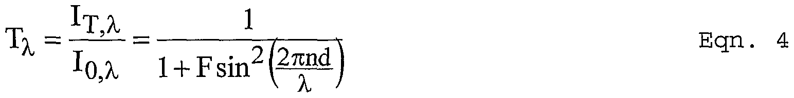
The capacity of a WDM or DWDM network is directly proportional to the number of optical signals, or channels, it transports. The initial 400-GHz to 800-GHz 8-channel systems that were deployed in medium and long haul network applications have quickly evolved into conventional C- band 100-GHz systems that incorporate more than 40 channels, but these systems are already beginning to reach their maximum capacities . Many vendors are looking to deploy solutions that will allow a) higher density channel spacing, and b) operations in both the C- band (1530 nm - 1563 nm) and the long L- band (1575 nm - 1610 nm) simultaneously. These changes will provide the capability to transport up to 256 channels of optical data on a single fiber.
As shown in Figure 12, a tunable Fabry-Perot interferometer with an initial optical path length of ca. 10 microns is characterized by a filter function 260 with a free spectral range (separation between two transmitted wavelengths) of ca. 125 nm in the C and L-band range. If
the optical path length is changed by 1 μm, then the transmitted peaks move horizontally by ca. 100 nm thereby scanning the C and the L bands . To provide the desired 256 channels, the filter function must exhibit a Finesse (FSR divided by the full width at half maximum) of at least ca. 200, preferably higher than 2000; and remain undistorted during tuning. As shown in Figure 12, the transmitted peaks become narrower as the mirror reflectivity (denoted next to the four traces) increases. The two mirrors must have high reflectivity, low loss and low surface defects and they must be aligned to nearly zero tilt between them in the initial state. Further, this alignment state must be maintained as the optical path length between them is changed over the desired range (i.e. by ca. 1 μm) . To achieve commercial success, the interferometer must also be cost effective, have low insertion losses, sufficiently rapid scan rates and remain thermally stable over a minimum ten year lifetime.
Currently the majority of commercially available scanning Fabry-Perot interferometers are based on a piezo-electric crystal technology. The movable mirror is mounted on a piezo electric material, which changes its dimensions in response to an applied voltage. Queensgate Instruments Limited produces a piezo controlled interferometer, early versions of which are described by T R Hicks, N K Reay and P D Atherton " The application of capacitance micrometry to the control of Fabry-Perot etalons" J. Physics E: Sci . Instrum. , Vol. 17, 19844 and European patent publication EP702205A2 entitled " Interferometer" to T R Hicks. U.S. Patent Nos .
4,400,058 and 4,553,816 also describe piezo electric interferometers. Piezo interferometers are complex, expensive, operate at high voltages, exhibit limited tuning ranges and have hysterisis and thermal drift problems .
Many attempts have been and are continuing to be made to apply classic silicon micromachining to solve the problems. In the silicon-MEMS based devices, electrodes are deposited onto both mirrors ~ thus an electrostatic force is created when a voltage is applied. The moveable mirror then moves against a semi-rigid silicon micromachined member, thereby changing the mirror separation. When the applied voltage is removed, the restoring force exerted by the semi-rigid member moves the moveable mirror back to its original configuration. US Patents 4 , 203 , 128 to Guckel ; 4 , 825, 262 to Mallinson; 4, 859, 060 to Katagiri ; 5, 561 , 523 to Blomberg; and 6, 078, 395 to Jourdain; PCT Application W099/34484 to Tayebati and E. Oilier; P. Mot tier X Micro-Opto-Electro- Mechanical Systems : Recent developments and LETI ' s activi ties" Proceedings of SPIE Vol . 4075, 2000 each describe variations on a silicon-MEMS based interferometer. These devices require complex processing techniques, which makes them expensive due to the high cost/low yield of precision lithography, exhibit a limited tuning range (ca. 40nm) due to material properties of silicon, and have difficulty maintaining a repeatable filter function during repeated tuning over long periods of time.
An anomalous technology, described in US Patent 5,068,861 entitled Etalon Apparatus, depicts a pair of mirrors separated by a compressible body portion (elastic spacer member) actuated with a helical compression spring via the rotation of a load adjustment knob. In theory, the helical compression spring could be controlled to squeeze the compressible body portion to select a desired wavelength for static operation. Clearly the manual operation of the adjustment knob and mechanical actuation are not suitable for scanning applications required by the telecommunications industry.
Tunable Fabry-Perot Interferometer Embodiments
In accordance with the present invention, a tunable Fabry-Perot interferometer that uses entropic materials reduces costs by reducing the capital investment in manufacturing, improving yield and reducing the external control needed to operate the device. First, entropic materials can be spun on, cured and, if necessary, patterned without the time consuming and very expensive deposition and precision lithography associated with conventional micromachining. Second, because the Young's modulus is orders of magnitude lower than enthalpic materials, the compliant member can be much thicker and relatively less precise for the same overall device performance tolerance ~ this in turn, also improves yield. Lastly, the improved device stability reduces the demands on external controls or feedback.
The use of entropic materials also greatly enhances the design space available for configuring a tunable
Fabry-Perot interferometer and, more specifically, the compliant member. As shown in Figures 14a-lie, the compliant member can be configured to undergo compressive, tensile, tensile/compressive, or shear deformation.
As shown in Figure 13a, two partially reflecting mirrors 1210, 1220 are separated by an entropic material 1230 such as an elastomer. The application of a command signal creates field lines (electrostatic or electromagnetic) that apply a force to move the movable mirror towards the fixed mirror thereby selecting different wavelengths. This embodiment is similar to the mechanically adjustable etalon described in the Λ 861 patent and appears to be the least viable configuration for a scanning mode device because of the incompressibility of the entropic material and the viscous flow and dissipative energy losses discussed in detail above. This is irrelevant in .the '861 implementation where mechanical control is used to tune and fix the wavelength but is critical in a computer controlled, automated scanning mode device.
As mentioned previously, the incorporation of defects in the elastomer network and/or small dopant molecules can significantly lower the viscosity. In addition, the entropic network itself can be modified (e.g. by swelling the network) to facilitate the flow of the dopant molecules. As a result, the device response time can be reduced to a point where scanning operation is possible. Another option is to use aerogels, which
are characterized by very small air bubbles in the material. These bubbles are compressible, which minimizes the viscous flow requirement and reduces the device time constant . As shown in Figure 13b, the flow problem can also be overcome by moving the entropic material outside the interferometer cavity and operating in a tensile mode (the electrostatic or electromagnetic force pulls downward on the movable mirror thereby stretching the entropic material) . More specifically, a thick entropic support layer 1310 is formed on the rigid support 1320 to hold the movable mirror 1330 parallel to the fixed mirror 134 in order to form the interferometer cavity 1350. In this case, the layer thickness can be significantly greater than the thickness of the interferometer cavity, and the time constants for the flow process become significantly smaller than the device scan rate. Thus, the elastomer becomes easy to deform and can operate in a scanning mode .
The compliant member for the movable mirror can be arranged in a diaphragm type layer undergoing tension/compression deformation (Figure 13c) or in a shear sandwich between two rigid plates undergoing shear deformation (Figure 13d) . These deformation modes involve either no or negligible volume change, hence do not require a net flow process. Therefore, the time constants for these deformation processes are very fast and the energy cost of misalignment is very high.
As discussed above, a shear vs. diaphragm device is differentiated only in the aspect ratio (i.e. the ratio of the height and lateral width) of the elastomer. When the elastomer layer resembles a sheet of paper, e.g. an aspect ratio less than 1, undergoing deformation lateral to the plane of the paper, then tensile/compressive forces accompany the deformation and the device is said to be in diaphragm mode. More specifically, entropic diaphragm 1410 is mounted on support 1420 to hold movable mirror 1430 parallel to fixed mirror 1440. When the elastomer layer has an aspect ratio greater than 10, the device is said to be in shear mode. More specifically, the moveable mirror 1530 is supported by an entropic sleeve 1510 mounted on a rigid support 1520 and held parallel to a fixed mirror 1540. Both these modes afford good elastic processes. Note, the diaphragm is on the order of 100 μm thick, which is 10 times thicker than conventional icromachined devices . The shear device also affords the additional stabilizing mechanisms described above .
As discussed above, for aspect ratios between 0.25 and 10, both shear and diaphragm modes of deflection affect the overall motion. As the aspect ratio increases above 1, the shear modes become dominant over the diaphragm modes. Further, as the aspect ratio increases above 10, the edge effects become negligible. A quasi shear device with aspect ratios between 1 and 10 (shown in Figure 13e) , provides a somewhat stable actuation of a shear device with the manufacturability of a diaphragm device.
While several illustrative embodiments of the invention have been shown and described, numerous variations and alternate embodiments will occur to those skilled in the art. Such variations and alternate embodiments are contemplated, and can be made without departing from the spirit and scope of the invention as defined in the appended claims .
Claims
1. A tunable optical component, comprising: a counter electrode; a movable optical element; a compliant member that supports the movable optical element, said compliant member being formed of a material that exhibits an entropic plateau region; and an electrostatic actuator for applying an electrostatic force that deforms the compliant member and moves the optical element as a function of an electric command signal .
2. The tunable optical component of claim 1, wherein the material comprises long chain polymers with at least 100 bonds per chain that are fully crosslinked at at least 90% of the bonds.
3. The tunable optical component of claim 2, wherein the material is selected from one of an elastomer, aerogel or long chain polymer.
4. The tunable optical component of claim 1, wherein the material exhibits a Young's modulus less than 5MPa in the entropic plateau region.
5. The tunable optical component of claim 1, wherein said optical element moves at a scan rate, the entropic plateau region extending over multiple frequency decade with an upper corner frequency at least one order of magnitude greater than the scan rate .
6. The tunable optical component of claim 1, wherein said movement deforms the compliant member over a deformation range, the material, hence the compliant member exhibits a linear elastic behavior over the entire deformation range.
7. The tunable optical component of claim 1, wherein the material is incompressible and the compliant member undergoes no volume change during deformation, said material exhibiting an energy cost of misalignment of the movable optical element that is at least an order of magnitude greater than the energy cost of deformation thereby self-stabilizing the optical element.
8. The tunable optical component of claim 1, wherein the material undergoes sheer deformation, said material exhibiting a normal stress that provides a force on the optical element perpendicular to the direction of motion thereby further self-stabilizing the optical element.
9. The tunable optical component of claim 1, wherein said movement scans the optical element with a time constant tscan, said material undergoes a volume change during deformation that causes a viscous flow with a time constant tresponse that is at least one order of magnitude less than tscan *
10. The tunable optical component of claim 9, wherein the material undergoes compressive stress during deformation, said material being doped with small molecules to reduce its viscosity such that tres onse i-s at least one order of magnitude less than
11. The tunable optical component of claim 9, wherein the material lies undergoes compressive stress during deformation, said material network is modified to reduce its viscosity such that tresponse is at least one order of magnitude less than tscan.
12. The tunable optical component of claim 9, wherein the material undergoes tensile stress during deformation, said material having a thickness such that tresponse is at least one order of magnitude less than tscan.
13. The tunable optical component of claim 1, wherein the compliant member and the material lie outside an optical path.
14. The tunable optical component of claim 1, wherein the compliant member forms a diaphragm that supports said movable optical element and undergoes tensile/compressive deformation response to said movement .
15. The tunable optical component of claim 14, wherein the diaphragm has an aspect ratio less than 1.
16. The tunable optical component of claim 1, wherein the compliant member forms a sleeve that supports the movable optical element and undergoes sheer deformation in response to the variable dimensioning.
17. The tunable optical component of claim 16, wherein the sleeve has an aspect ratio greater than 1.
18. The tunable optical component of claim 16, wherein the material undergoes no volume change during sheer deformation such that the energy cost of misalignment of the movable optical element is at least an order of magnitude greater than the energy cost of deformation thereby self-stabilizing the movable optical element.
19. The tunable optical component of claim 16, wherein the material exhibits a normal stress that provides a force on the movable optical element perpendicular to the direction of motion thereby* further self-stabilizing the movable optical element .
20. A tunable Fabry-Perot interferometer, comprising: a fixed partially reflective mirror; a movable partially reflective mirror disposed parallel to the fixed mirror; a compliant member that supports the movable mirror so as to permit variable dimensioning of an optical Fabry-Perot interferometer cavity formed between the fixed and movable mirrors, said compliant member being formed of a material that exhibits an entropic plateau region; and
an actuator for creating field lines that apply a force to said movable mirror that deforms the compliant member and controls said variable dimensioning as a function of an electric command signal .
21. The tunable Fabry-Perot interferometer of claim 20, wherein the material comprises long chain polymers with at least 100 bonds per chain that are fully crosslinked at at least 90% of the bonds.
22. The tunable Fabry-Perot interferometer of claim 21, wherein the material is selected from one of an elastomer, aerogel or long chain polymer.
23. The tunable Fabry-Perot interferometer of claim 20, wherein the material exhibits a Young's modulus less than 5MPa in the entropic plateau region.
24. The tunable Fabry-Perot interferometer of claim 20, wherein said variable dimensioning scans a filter function across a range of wavelengths at a scan rate, the entropic plateau region extending over multiple frequency decade with ah upper corner frequency at least one order of magnitude greater than the scan rate .
25. The tunable Fabry-Perot interferometer of claim 20, wherein said variable dimensioning deforms the compliant member over a deformation range, the material, hence the compliant member exhibiting a linear elastic behavior over the entire deformation range .
26. The tunable Fabry-Perot interferometer of claim 20, wherein the material is incompressible and the compliant member undergoes no volume change during deformation, said material exhibiting an energy cost of misalignment of the movable mirror that is at least an order of magnitude greater than the energy cost of deformation thereby self- stabilizing the movable mirror.
27. The tunable Fabry-Perot interferometer of claim 20, wherein the material undergoes sheer deformation, said . material exhibiting a normal stress that provides a force on the movable mirror perpendicular to the direction of motion thereby further self-stabilizing the movable mirror.
28. The tunable Fabry-Perot interferometer of claim 20, wherein said variable dimensioning scans a filter function across a range of wavelengths with a time constant tscan, said material undergoes a volume change during deformation that causes a viscous flow with a time constant tresponse that is at least one order of magnitude less than tscan.
29. The tunable Fabry-Perot interferometer of claim 28, wherein the material lies inside the interferometer cavity and undergoes compressive stress during deformation, said material being doped with small molecules to reduce its viscosity such that tresponse is at least one order of magnitude less than t -βscan •
30. The tunable Fabry-Perot interferometer of claim 28, wherein the material lies inside the interferometer cavity and undergoes compressive stress during deformation, said material network is modified to reduce its viscosity such that tresponse is at least one order of magnitude less than tscan.
31. The tunable Fabry-Perot interferometer of claim 28, wherein the material lies outside the interferometer cavity on the movable mirror and undergoes tensile stress during deformation, said material having a thickness greater than the separation between said fixed and movable mirrors such that tresponse is at least one order of magnitude less than tscan.
32. The tunable Fabry-Perot interferometer of claim 20, wherein the compliant member and the material lie outside the interferometer cavity.
33. The tunable Fabry-Perot interferometer of claim 20, wherein the compliant member forms a diaphragm that supports said movable mirror and undergoes tensile/compressive deformation response to said variable dimensioning.
34. The tunable Fabry-Perot interferometer of claim 33, wherein the diaphragm has an aspect ratio less than 1.
35. The tunable Fabry-Perot interferometer of claim 20, wherein the compliant member forms a sleeve that supports the movable mirror and undergoes sheer deformation in response to the variable dimensioning.
36. The tunable Fabry-Perot interferometer of claim 35, wherein the sleeve has an aspect ratio greater than 10.
37. The tunable Fabry-Perot interferometer of claim 35, wherein the material undergoes no volume change during sheer deformation such that the energy cost of misalignment of the movable mirror is at least an order of magnitude greater than the energy cost of deformation thereby self-stabilizing the movable mirror.
38. The tunable Fabry-Perot interferometer of claim 35, wherein the material exhibits a normal stress that provides a force on the movable mirror perpendicular to the direction of motion thereby further self-stabilizing the movable mirror.
39. The tunable Fabry-Perot interferometer of claim 20, wherein the actuator is an electrostatic actuator that creates electric field lines to produce the force on the movable mirror.
40. The tunable Fabry-Perot interferometer of claim 20, wherein the actuator is an electromagnetic actuator that creates magnetic field lines to produce the force on the movable mirror.
41. A tunable Fabry-Perot interferometer, comprising:
a fixed partially reflective mirror; a movable partially reflective mirror disposed parallel to the fixed mirror; a compliant member that supports the movable mirror so as to permit variable dimensioning of an optical Fabry-Perot interferometer cavity formed between the fixed and movable mirrors; and
an actuator that applies a force to said movable mirror that deforms the compliant member over a deformation range to control said variable dimensioning thereby scanning a filter function formed by the interferometer cavity across a desired range of wavelengths,
said compliant member being formed of a material that exhibits a Young's modulus of less than 5 MPa across an entropic plateau region that extends over multiple frequency decades including an upper corner frequency at least one order of magnitude above the scan rate and exhibits linear elastic behavior over the entire deformation range.
42. The tunable Fabry-Perot interferometer of claim 41, wherein the material comprises long chain polymers with at least 100 bonds per chain that are fully crosslinked at least 90% of the bonds.
43. The tunable Fabry-Perot interferometer of claim 41, wherein the material is selected from one of an elastomer, aerogel or long chain polymer.
44. The tunable Fabry-Perot interferometer of claim 41, wherein the material is incompressible and the compliant member undergoes no volume change during deformation, said material exhibiting an energy cost of misalignment of the movable mirror that is at least an order of magnitude greater than the energy cost of deformation thereby self- stabilizing the movable mirror.
45. The tunable Fabry-Perot interferometer of claim 41, wherein the material exhibits a normal stress that provides a force on the movable mirror perpendicular to the direction of motion thereby further self-stabilizing the movable mirror.
46. A tunable Fabry-Perot interferometer, comprising: a fixed partially reflective mirror; a movable partially reflective mirror disposed parallel to the fixed mirror; a compliant member that supports the movable mirror so as to permit variable dimensioning of an optical Fabry-Perot interferometer cavity formed between the fixed and movable mirrors, said compliant member being formed of a material that lies outside the cavity and exhibits an entropic plateau region; and
an actuator that applies a force to said movable mirror that deforms the compliant member without causing a volume change in the material to control said* variable dimensioning, said material exhibiting an energy cost of misalignment of the movable mirror that is at least an order of magnitude greater than the energy cost of deformation thereby self- stabilizing the movable mirror.
47. The tunable Fabry-Perot interferometer of claim 46, wherein said variable dimensioning scans a filter function across a range of wavelengths at a scan rate, the entropic plateau region extending over multiple frequency decade with an upper corner frequency at least one order of magnitude greater than the scan rate .
48. The tunable Fabry-Perot interferometer of claim 46, wherein said variable dimensioning deforms the compliant member over a deformation range, the material, hence the compliant member exhibiting a linear elastic behavior over the entire deformation range .
49. The tunable Fabry-Perot interferometer of claim 46, wherein the sleeve has an aspect ratio greater than 10.
50. The tunable Fabry-Perot interferometer of claim 46, wherein the material exhibits a normal stress that provides a force on the movable mirror perpendicular to the direction of motion thereby further self-stabilizing the movable mirror.
51. A tunable Fabry-Perot interferometer, comprising: a fixed partially reflective mirror; a movable partially reflective mirror disposed parallel to the fixed mirror; a compliant diaphragm that supports the movable mirror so as to permit variable dimensioning of an optical Fabry-Perot interferometer cavity formed between the fixed and movable mirrors, said diaphragm being formed of a material that exhibits an entropic plateau region; and
an actuator for creating field lines that apply a force to said movable mirror that deforms the compliant diaphragm, which undergoes tensile/compressive deformation, and controls said variable dimensioning as a function of an electric command signal .
52. The tunable Fabry-Perot interferometer of claim 51, wherein the material exhibits a Young's modulus less than 5Mpa in the entropic plateau region.
53. The tunable Fabry-Perot interferometer of claim 51, wherein said variable dimensioning scans a filter function across a range of wavelengths at a scan rate, the entropic plateau region extending over multiple frequency decade with an upper corner frequency at least one order of magnitude greater than the scan rate.
54. The tunable Fabry-Perot interferometer of claim 51, wherein said variable dimensioning deforms the compliant member over a deformation range, the material, hence the compliant member exhibiting a linear elastic behavior over the entire deformation range .
55. The tunable Fabry-Perot interferometer of claim 51, wherein the diaphragm has an aspect ratio less than 1.
Priority Applications (1)
| Application Number | Priority Date | Filing Date | Title |
|---|---|---|---|
| AU2001249289A AU2001249289A1 (en) | 2000-03-20 | 2001-03-20 | Electrostatically-actuated tunable optical components using entropic materials |
Applications Claiming Priority (8)
| Application Number | Priority Date | Filing Date | Title |
|---|---|---|---|
| US19011000P | 2000-03-20 | 2000-03-20 | |
| US60/190,110 | 2000-03-20 | ||
| US60/209,992 | 2000-06-08 | ||
| US21152900P | 2000-06-15 | 2000-06-15 | |
| US60/211,529 | 2000-06-15 | ||
| US60/213,480 | 2000-06-23 | ||
| US09/766,687 US6597461B1 (en) | 2000-03-20 | 2001-01-19 | Tunable fabry-perot interferometer using entropic materials |
| US09/766,687 | 2001-01-19 |
Publications (1)
| Publication Number | Publication Date |
|---|---|
| WO2001071277A1 true WO2001071277A1 (en) | 2001-09-27 |
Family
ID=27392687
Family Applications (1)
| Application Number | Title | Priority Date | Filing Date |
|---|---|---|---|
| PCT/US2001/008893 WO2001071277A1 (en) | 2000-03-20 | 2001-03-20 | Electrostatically-actuated tunable optical components using entropic materials |
Country Status (3)
| Country | Link |
|---|---|
| US (1) | US6519074B2 (en) |
| AU (1) | AU2001249289A1 (en) |
| WO (1) | WO2001071277A1 (en) |
Cited By (1)
| Publication number | Priority date | Publication date | Assignee | Title |
|---|---|---|---|---|
| WO2004014963A3 (en) * | 2002-08-09 | 2004-08-05 | Univ Carnegie Mellon | Polymers, supersoft elastomers and methods for preparing the same |
Families Citing this family (20)
| Publication number | Priority date | Publication date | Assignee | Title |
|---|---|---|---|---|
| US6407851B1 (en) | 2000-08-01 | 2002-06-18 | Mohammed N. Islam | Micromechanical optical switch |
| US6795605B1 (en) * | 2000-08-01 | 2004-09-21 | Cheetah Omni, Llc | Micromechanical optical switch |
| US6775043B1 (en) * | 2000-08-21 | 2004-08-10 | Blue Sky Research | Reflector assemblies for optical cross-connect switches and switches fabricated therefrom |
| US6721473B1 (en) | 2001-02-02 | 2004-04-13 | Cheetah Omni, Llc | Variable blazed grating based signal processing |
| US7145704B1 (en) | 2003-11-25 | 2006-12-05 | Cheetah Omni, Llc | Optical logic gate based optical router |
| WO2005034754A1 (en) * | 2003-10-15 | 2005-04-21 | The University Of British Columbia | Methods and apparatus for urodynamic analysis |
| CN101095277A (en) | 2004-03-12 | 2007-12-26 | 斯里国际 | Mechanical meta-materials |
| US7061660B1 (en) * | 2005-04-13 | 2006-06-13 | Hewlett-Packard Development Company, L.P. | MEMs device with feedback control |
| US7551419B2 (en) * | 2006-06-05 | 2009-06-23 | Sri International | Electroadhesion |
| US7554787B2 (en) * | 2006-06-05 | 2009-06-30 | Sri International | Wall crawling devices |
| US7817281B2 (en) * | 2007-02-05 | 2010-10-19 | Palo Alto Research Center Incorporated | Tuning optical cavities |
| US7936463B2 (en) * | 2007-02-05 | 2011-05-03 | Palo Alto Research Center Incorporated | Containing analyte in optical cavity structures |
| US7633629B2 (en) * | 2007-02-05 | 2009-12-15 | Palo Alto Research Center Incorporated | Tuning optical cavities |
| US20080297928A1 (en) * | 2007-06-01 | 2008-12-04 | Crowe Devon G | Low mass optical device and method |
| US8659835B2 (en) | 2009-03-13 | 2014-02-25 | Optotune Ag | Lens systems and method |
| US8699141B2 (en) | 2009-03-13 | 2014-04-15 | Knowles Electronics, Llc | Lens assembly apparatus and method |
| WO2013066447A1 (en) | 2011-08-01 | 2013-05-10 | The Trustees Of Columbia University In The City Of New York | Lens-free planar imager and wireless transmitter |
| WO2013059665A1 (en) | 2011-10-19 | 2013-04-25 | The Trustees Of Columbia University In The City Of New York | Ultracompact fabry-perot array for ultracompact hyperspectral imaging |
| WO2013148349A1 (en) | 2012-03-30 | 2013-10-03 | The Trustees Of Columbia University In The City Of New York | Graphene photonics for resonator-enhanced electro-optic devices and all-optical interactions |
| US9212948B2 (en) | 2012-11-07 | 2015-12-15 | The Trustees Of Columbia University In The City Of New York | Lossless hyperspectral imaging |
Citations (5)
| Publication number | Priority date | Publication date | Assignee | Title |
|---|---|---|---|---|
| US5381232A (en) * | 1992-05-19 | 1995-01-10 | Akzo Nobel N.V. | Fabry-perot with device mirrors including a dielectric coating outside the resonant cavity |
| US5461507A (en) * | 1990-06-05 | 1995-10-24 | Enichem S.P.A. | Polymer material of thermo-optical effect for a bistable optical device |
| US5510914A (en) * | 1993-11-15 | 1996-04-23 | The Regents Of The University Of Colorado | Smectic liquid crystal analog phase modulator |
| US5970190A (en) * | 1996-12-02 | 1999-10-19 | Photonics Research Ontario | Grating-in-etalon polarization insensitive wavelength division multiplexing devices |
| US6137819A (en) * | 1996-03-13 | 2000-10-24 | Sharp Kabushiki Kaisha | Optoelectronic semiconductor device |
Family Cites Families (17)
| Publication number | Priority date | Publication date | Assignee | Title |
|---|---|---|---|---|
| US4203128A (en) | 1976-11-08 | 1980-05-13 | Wisconsin Alumni Research Foundation | Electrostatically deformable thin silicon membranes |
| US4400058A (en) | 1980-06-16 | 1983-08-23 | Honeywell Inc. | Tunable Fabry-Perot filter |
| US4553816A (en) | 1980-12-15 | 1985-11-19 | Honeywell Inc. | Tunable Fabry-Perot filter |
| EP0223414B1 (en) | 1985-10-16 | 1994-01-12 | BRITISH TELECOMMUNICATIONS public limited company | Mounting a component to a substrate |
| GB2186708B (en) | 1985-11-26 | 1990-07-11 | Sharp Kk | A variable interferometric device and a process for the production of the same |
| US5068861A (en) | 1990-07-19 | 1991-11-26 | Spectra-Physics Lasers, Inc. | Etalon apparatus |
| FI94804C (en) | 1994-02-17 | 1995-10-25 | Vaisala Oy | Electrically adjustable surface micromechanical Fabry-Perot interferometer for optical material analysis |
| RU2143127C1 (en) | 1994-09-02 | 1999-12-20 | Рэд Хассан Дэббедж | Modulator of light-valve system of reflection type |
| GB9418738D0 (en) | 1994-09-16 | 1994-11-02 | Queensgate Instr Ltd | Interferometer |
| JP3517535B2 (en) * | 1996-07-10 | 2004-04-12 | 日本碍子株式会社 | Display device |
| US5969848A (en) * | 1997-07-03 | 1999-10-19 | The Regents Of The University Of California | Micromachined electrostatic vertical actuator |
| US5867302A (en) * | 1997-08-07 | 1999-02-02 | Sandia Corporation | Bistable microelectromechanical actuator |
| FR2768812B1 (en) | 1997-09-19 | 1999-10-22 | Commissariat Energie Atomique | FABRY-PEROT INTERFEROMETER TUNABLE INTEGRATED |
| AU764799B2 (en) | 1997-12-29 | 2003-08-28 | Coretek, Inc. | Microelectromechanically tunable, confocal, vertical cavity surface emitting laser and fabry-perot filter |
| US6428173B1 (en) * | 1999-05-03 | 2002-08-06 | Jds Uniphase, Inc. | Moveable microelectromechanical mirror structures and associated methods |
| US6236491B1 (en) * | 1999-05-27 | 2001-05-22 | Mcnc | Micromachined electrostatic actuator with air gap |
| US6229640B1 (en) * | 1999-08-11 | 2001-05-08 | Adc Telecommunications, Inc. | Microelectromechanical optical switch and method of manufacture thereof |
-
2001
- 2001-03-20 US US09/811,612 patent/US6519074B2/en not_active Expired - Fee Related
- 2001-03-20 AU AU2001249289A patent/AU2001249289A1/en not_active Abandoned
- 2001-03-20 WO PCT/US2001/008893 patent/WO2001071277A1/en active Application Filing
Patent Citations (5)
| Publication number | Priority date | Publication date | Assignee | Title |
|---|---|---|---|---|
| US5461507A (en) * | 1990-06-05 | 1995-10-24 | Enichem S.P.A. | Polymer material of thermo-optical effect for a bistable optical device |
| US5381232A (en) * | 1992-05-19 | 1995-01-10 | Akzo Nobel N.V. | Fabry-perot with device mirrors including a dielectric coating outside the resonant cavity |
| US5510914A (en) * | 1993-11-15 | 1996-04-23 | The Regents Of The University Of Colorado | Smectic liquid crystal analog phase modulator |
| US6137819A (en) * | 1996-03-13 | 2000-10-24 | Sharp Kabushiki Kaisha | Optoelectronic semiconductor device |
| US5970190A (en) * | 1996-12-02 | 1999-10-19 | Photonics Research Ontario | Grating-in-etalon polarization insensitive wavelength division multiplexing devices |
Cited By (2)
| Publication number | Priority date | Publication date | Assignee | Title |
|---|---|---|---|---|
| WO2004014963A3 (en) * | 2002-08-09 | 2004-08-05 | Univ Carnegie Mellon | Polymers, supersoft elastomers and methods for preparing the same |
| US7019082B2 (en) | 2002-08-09 | 2006-03-28 | Carnegie Mellon University | Polymers, supersoft elastomers and methods for preparing the same |
Also Published As
| Publication number | Publication date |
|---|---|
| AU2001249289A1 (en) | 2001-10-03 |
| US6519074B2 (en) | 2003-02-11 |
| US20010055147A1 (en) | 2001-12-27 |
Similar Documents
| Publication | Publication Date | Title |
|---|---|---|
| WO2001071277A1 (en) | Electrostatically-actuated tunable optical components using entropic materials | |
| US6597461B1 (en) | Tunable fabry-perot interferometer using entropic materials | |
| US5914804A (en) | Double-cavity micromechanical optical modulator with plural multilayer mirrors | |
| US5862003A (en) | Micromotion amplifier | |
| US6556338B2 (en) | MEMS based variable optical attenuator (MBVOA) | |
| US5022745A (en) | Electrostatically deformable single crystal dielectrically coated mirror | |
| EP1135701B1 (en) | Compression-tuned bragg grating and laser | |
| Correia et al. | Bulk-micromachined tunable Fabry–Perot microinterferometer for the visible spectral range | |
| KR20020093830A (en) | Temperature compensated optical device | |
| CA2462810A1 (en) | Beam-steering optical-switching apparatus | |
| EP1403210A2 (en) | Microelectromechanical device with continuously variable displacement | |
| US20080239431A1 (en) | Micromechanical device of increased rigidity | |
| US20090110009A1 (en) | Optical fiber grating tuning device and optical systems employing same | |
| EP0875019B1 (en) | Optical device | |
| CN1828352A (en) | Colorless tunable dispersion compensator employing a planar lightwave circuit and a deformable mirror | |
| US20050105849A1 (en) | Thermally actuated wavelength tunable optical filter | |
| US7999213B2 (en) | Compact high-speed thin micromachined membrane deformable mirror | |
| EP1146377B1 (en) | Tunable Fabry-Perot filters and lasers with reduced frequency noise | |
| JP2009053458A (en) | Variable wavelength filter | |
| JP2006525510A (en) | Adjustable Fabry-Perot filter | |
| Aksyuk et al. | Optical MEMS design for telecommunications applications | |
| EP1498752B1 (en) | Temperature-compensated fiber grating packaging arrangement | |
| Eliahou-Niv et al. | Design and analysis of a novel tunable optical filter | |
| US6763152B2 (en) | Optical fiber equipment with a Bragg grating tunable by a piezoelectric actuator | |
| Okumura et al. | PZT MEMS-VCSEL for precise and high-speed wavelength tuning |
Legal Events
| Date | Code | Title | Description |
|---|---|---|---|
| AK | Designated states |
Kind code of ref document: A1 Designated state(s): AE AG AL AM AT AU AZ BA BB BG BR BY BZ CA CH CN CO CR CU CZ DE DK DM DZ EE ES FI GB GD GE GH GM HR HU ID IL IN IS JP KE KG KP KR KZ LC LK LR LS LT LU LV MA MD MG MK MN MW MX MZ NO NZ PL PT RO RU SD SE SG SI SK SL TJ TM TR TT TZ UA UG US UZ VN YU ZA ZW |
|
| AL | Designated countries for regional patents |
Kind code of ref document: A1 Designated state(s): GH GM KE LS MW MZ SD SL SZ TZ UG ZW AM AZ BY KG KZ MD RU TJ TM AT BE CH CY DE DK ES FI FR GB GR IE IT LU MC NL PT SE TR BF BJ CF CG CI CM GA GN GW ML MR NE SN TD TG |
|
| 121 | Ep: the epo has been informed by wipo that ep was designated in this application | ||
| DFPE | Request for preliminary examination filed prior to expiration of 19th month from priority date (pct application filed before 20040101) | ||
| 122 | Ep: pct application non-entry in european phase | ||
| NENP | Non-entry into the national phase |
Ref country code: JP |