WO2002054990A2 - Stent treatment apparatus and method - Google Patents
Stent treatment apparatus and method Download PDFInfo
- Publication number
- WO2002054990A2 WO2002054990A2 PCT/US2002/000736 US0200736W WO02054990A2 WO 2002054990 A2 WO2002054990 A2 WO 2002054990A2 US 0200736 W US0200736 W US 0200736W WO 02054990 A2 WO02054990 A2 WO 02054990A2
- Authority
- WO
- WIPO (PCT)
- Prior art keywords
- stent
- fluid
- washing
- treatment apparatus
- stents
- Prior art date
Links
Classifications
-
- A—HUMAN NECESSITIES
- A61—MEDICAL OR VETERINARY SCIENCE; HYGIENE
- A61L—METHODS OR APPARATUS FOR STERILISING MATERIALS OR OBJECTS IN GENERAL; DISINFECTION, STERILISATION OR DEODORISATION OF AIR; CHEMICAL ASPECTS OF BANDAGES, DRESSINGS, ABSORBENT PADS OR SURGICAL ARTICLES; MATERIALS FOR BANDAGES, DRESSINGS, ABSORBENT PADS OR SURGICAL ARTICLES
- A61L2/00—Methods or apparatus for disinfecting or sterilising materials or objects other than foodstuffs or contact lenses; Accessories therefor
- A61L2/16—Methods or apparatus for disinfecting or sterilising materials or objects other than foodstuffs or contact lenses; Accessories therefor using chemical substances
- A61L2/18—Liquid substances or solutions comprising solids or dissolved gases
-
- A—HUMAN NECESSITIES
- A61—MEDICAL OR VETERINARY SCIENCE; HYGIENE
- A61B—DIAGNOSIS; SURGERY; IDENTIFICATION
- A61B90/00—Instruments, implements or accessories specially adapted for surgery or diagnosis and not covered by any of the groups A61B1/00 - A61B50/00, e.g. for luxation treatment or for protecting wound edges
- A61B90/70—Cleaning devices specially adapted for surgical instruments
-
- A—HUMAN NECESSITIES
- A61—MEDICAL OR VETERINARY SCIENCE; HYGIENE
- A61F—FILTERS IMPLANTABLE INTO BLOOD VESSELS; PROSTHESES; DEVICES PROVIDING PATENCY TO, OR PREVENTING COLLAPSING OF, TUBULAR STRUCTURES OF THE BODY, e.g. STENTS; ORTHOPAEDIC, NURSING OR CONTRACEPTIVE DEVICES; FOMENTATION; TREATMENT OR PROTECTION OF EYES OR EARS; BANDAGES, DRESSINGS OR ABSORBENT PADS; FIRST-AID KITS
- A61F2/00—Filters implantable into blood vessels; Prostheses, i.e. artificial substitutes or replacements for parts of the body; Appliances for connecting them with the body; Devices providing patency to, or preventing collapsing of, tubular structures of the body, e.g. stents
- A61F2/95—Instruments specially adapted for placement or removal of stents or stent-grafts
- A61F2/9517—Instruments specially adapted for placement or removal of stents or stent-grafts handle assemblies therefor
-
- A—HUMAN NECESSITIES
- A61—MEDICAL OR VETERINARY SCIENCE; HYGIENE
- A61B—DIAGNOSIS; SURGERY; IDENTIFICATION
- A61B90/00—Instruments, implements or accessories specially adapted for surgery or diagnosis and not covered by any of the groups A61B1/00 - A61B50/00, e.g. for luxation treatment or for protecting wound edges
- A61B90/70—Cleaning devices specially adapted for surgical instruments
- A61B2090/701—Cleaning devices specially adapted for surgical instruments for flexible tubular instruments, e.g. endoscopes
-
- A—HUMAN NECESSITIES
- A61—MEDICAL OR VETERINARY SCIENCE; HYGIENE
- A61F—FILTERS IMPLANTABLE INTO BLOOD VESSELS; PROSTHESES; DEVICES PROVIDING PATENCY TO, OR PREVENTING COLLAPSING OF, TUBULAR STRUCTURES OF THE BODY, e.g. STENTS; ORTHOPAEDIC, NURSING OR CONTRACEPTIVE DEVICES; FOMENTATION; TREATMENT OR PROTECTION OF EYES OR EARS; BANDAGES, DRESSINGS OR ABSORBENT PADS; FIRST-AID KITS
- A61F2/00—Filters implantable into blood vessels; Prostheses, i.e. artificial substitutes or replacements for parts of the body; Appliances for connecting them with the body; Devices providing patency to, or preventing collapsing of, tubular structures of the body, e.g. stents
- A61F2/82—Devices providing patency to, or preventing collapsing of, tubular structures of the body, e.g. stents
- A61F2/86—Stents in a form characterised by the wire-like elements; Stents in the form characterised by a net-like or mesh-like structure
- A61F2/90—Stents in a form characterised by the wire-like elements; Stents in the form characterised by a net-like or mesh-like structure characterised by a net-like or mesh-like structure
- A61F2/91—Stents in a form characterised by the wire-like elements; Stents in the form characterised by a net-like or mesh-like structure characterised by a net-like or mesh-like structure made from perforated sheet material or tubes, e.g. perforated by laser cuts or etched holes
-
- A—HUMAN NECESSITIES
- A61—MEDICAL OR VETERINARY SCIENCE; HYGIENE
- A61F—FILTERS IMPLANTABLE INTO BLOOD VESSELS; PROSTHESES; DEVICES PROVIDING PATENCY TO, OR PREVENTING COLLAPSING OF, TUBULAR STRUCTURES OF THE BODY, e.g. STENTS; ORTHOPAEDIC, NURSING OR CONTRACEPTIVE DEVICES; FOMENTATION; TREATMENT OR PROTECTION OF EYES OR EARS; BANDAGES, DRESSINGS OR ABSORBENT PADS; FIRST-AID KITS
- A61F2250/00—Special features of prostheses classified in groups A61F2/00 - A61F2/26 or A61F2/82 or A61F9/00 or A61F11/00 or subgroups thereof
- A61F2250/0058—Additional features; Implant or prostheses properties not otherwise provided for
- A61F2250/0067—Means for introducing or releasing pharmaceutical products into the body
-
- Y—GENERAL TAGGING OF NEW TECHNOLOGICAL DEVELOPMENTS; GENERAL TAGGING OF CROSS-SECTIONAL TECHNOLOGIES SPANNING OVER SEVERAL SECTIONS OF THE IPC; TECHNICAL SUBJECTS COVERED BY FORMER USPC CROSS-REFERENCE ART COLLECTIONS [XRACs] AND DIGESTS
- Y10—TECHNICAL SUBJECTS COVERED BY FORMER USPC
- Y10T—TECHNICAL SUBJECTS COVERED BY FORMER US CLASSIFICATION
- Y10T137/00—Fluid handling
- Y10T137/0318—Processes
- Y10T137/0324—With control of flow by a condition or characteristic of a fluid
- Y10T137/0379—By fluid pressure
Definitions
- the invention relates generally to the field of angioplasty and more specifically to stent implantation after angioplasty. More specifically, the invention relates to methods and means of reducing coronary restenosis.
- Coronary restenosis after angioplasty and stent implantation placement remains a substantial problem, as outlined by Willerson, J.T., 1997, Circulation, 96:383-385. While recent randomized studies show that stent implantation reduces restenosis significantly compared to balloon angioplasty (see Rankin, J.M., et al., 1999, NEnglJMed, 341:2005-6), stents have not eliminated restenosis, especially in complex lesion subsets such as diffuse disease and small vessels. The observation that in-stent restenosis may be diffuse suggests that a generalized reaction to the stent may be a possible etiology.
- Such a reaction might be to the metal, or alternatively from residual contaminants on the stent from the manufacturing process, as described by Shih, C.C. et al., 2000, J Biomed Mater Res, 52:395-403.
- Previous animal studies established a significant correlation between the degree of arterial injury caused by metallic wire coils and the resultant neointimal thickness and lumen stenosis at the stent site. See Schwartz, R.S. et al, 1992, J Am Coll Cadiol, 19:267-74, and Karas, S.P. et al., 1992, J Am Coll Cardiol, 20:467-74.
- a stent treatment apparatus that includes a stent washing chamber that is configured to accept a stent, a fluid inflow port, and a fluid outflow port.
- the fluid inflow port and the fluid outflow port are in fluid cornmunication with the stent washing chamber.
- the invention is also found in a stent treatment apparatus that includes stent washing means for pressure washing a stent preloaded on a balloon catheter, as well as fluid inflow means for providing a washing fluid to the stent washing means and fluid outflow means for removing the washing fluid from the stent washing means.
- the apparatus also includes receiving means for receiving a catheter within the stent washing apparatus.
- the invention is also found in a stent delivery system that includes a stent and a stent washing apparatus, where the apparatus includes a stent washing chamber that has an inlet, an outlet, and a central region configured to accept a stent.
- the apparatus also has a fluid inflow port and a fluid outflow port, with the fluid inflow port and the fluid outflow port in fluid communication with the stent washing chamber.
- the invention is also found in a method of delivering a stent.
- the method includes steps of placing a preloaded stent into a stent washing apparatus, contacting the preloaded stent with a washing fluid under pressure, removing the washing fluid, and extending the preloaded stent beyond the stent washing apparatus into a touhy.
- the invention is also found in a method of loading a stent with a drug.
- the method includes steps of placing a preloaded stent into a stent washing apparatus, contacting the preloaded stent with a solution comprising a drug, providing sufficient residence time to permit transfer ofthe drug into and onto the stent, removing the drug solution, and extending the preloaded stent beyond the stent washing apparatus into a touhy.
- Figure 1 is a cross-sectional view of a stent treatment apparatus in accordance with a preferred embodiment ofthe present invention.
- Figure 2 is a cross-sectional view of a stent treatment apparatus in accordance with a preferred embodiment ofthe present invention, illustrating the relative placement of a balloon catheter bearing a preloaded stent and a guide wire. An inflation device for providing a treatment or wash fluid under pressure is also illustrated.
- Figure 3 is a diagrammatical view of a sheath, a guide catheter and a touhy, to which a stent treatment apparatus can be attached in accordance with a preferred embodiment ofthe present invention.
- Figure 4 represents a stent-cleaning chamber as used in the working examples described hereinafter.
- Figures 5A-5I provide an examination ofthe stent surface of six pre-mounted balloon-expandable 16-mm NIR stents that were expanded ex-vivo under sterile conditions as untouched, handled, and rinsed and evaluated by scanning electron microscope.
- Figures 6A and 6B provide representative linear fit curves for injury- dependent neointimal thickness in the four studied groups.
- Figure 6A shows regression lines for handled and handled+rinsed stents
- Figure 6B shows injury-dependent neointimal thickness regression lines for untouched and untouched+rinsed stents.
- Figures 7 A and 7B are histologic examples of handled and handled+rinsed stents.
- the two arteries have a similar mean injury score but a different neointimal response.
- the thicker neomtima in the handled stent artery overlies the struts that elicited more inflammation (in asterisks) while in Figure 7B, handled+rinsed struts elicited minimal neointima even with severe medial damage (arrows).
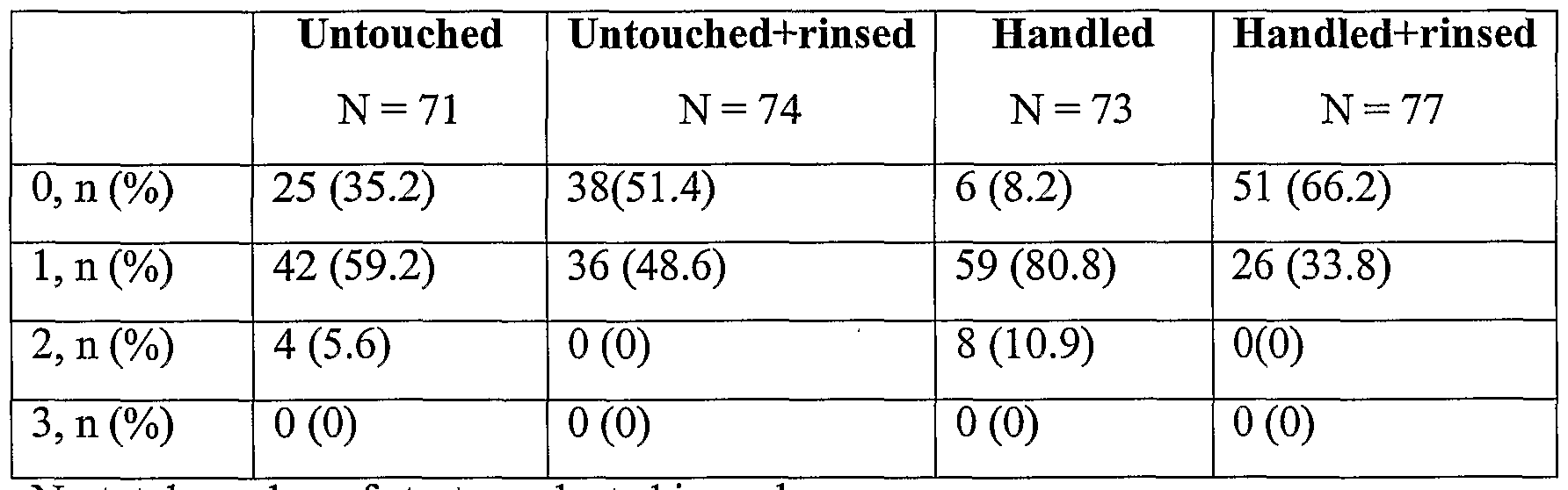
- Figure 8 provides inflammation scores for the four studied groups.
- Figure 9A provides representative linear fit curves of injury-dependent inflammation in the four studied groups while Figures 9B, 9C, and 9D are hematoxylin-eosin microphotographs of peri-strut inflammation.
- the present invention is directed to methods, means and apparatuses for washing stents prior to implantation.
- this washing procedure results in a stent that bears fewer foreign contaminants and thus causes a reduced level of inflammation once the stent is implanted.
- a stent is frequently used as part of a balloon angioplasty procedure. This procedure is often-times referred to as a percutaneous transluminal coronary angioplasty (PTCA) procedure.
- PTCA percutaneous transluminal coronary angioplasty
- an angioplasty procedure is called for when one or more ofthe arteries providing blood to the heart are partially or completely obstructed.
- a small balloon is placed within the constriction in the artery and is inflated, thereby forcing the constriction to open up.
- Angioplasty typically begins by making a needle puncture in the femoral artery, which is located in the patient's groin.
- a short tube called a sheath is placed through the needle puncture and extends into the femoral artery.
- the sheath can function as an access port for the catheters used to open the blockages or constrictions present in the cardiac arteries.
- a guide catheter is inserted into the sheath and follows the femoral artery to the aorta, through the aorta and into position within the subject artery. Contrast dyes can be used so that the physician can visualize the obstructions.
- a guide wire is placed within the guide catheter and preferably is inserted such that it extends through and beyond the particular blockage of interest.
- the guide wire can function as a track for the balloon catheter that follows.
- the balloon catheter is fed along the guide wire until the un-inflated balloon is in position within the blockage.
- the balloon is slowly inflated, which is intended to remove the constriction within the artery.
- the balloon is deflated and contrast dye is again injected into the artery to see if the interior volume ofthe artery has been increased.
- a stent is placed within the previously blocked area to help prevent restenosis, which refers to the artery re-narrowing itself after the angioplasty procedure.
- another balloon catheter that bears a compressed, preloaded stent can be advanced along the guide wire until the stent is in position within the previously blocked area.
- the balloon is inflated, which expands and positions the stent.
- FIG 3 is a schematic illustration ofthe equipment used to place a stent within an artery.
- One end ofthe sheath 30 is placed within a needle puncture made in the femoral artery, as described above.
- a second end ofthe sheath 30 extends beyond the patient's skin and includes a coupling 32.
- the coupling 32 includes a side arm 34 that can be used for a variety of different purposes, although injecting dye is probably the most common use for the side arm 34.
- the coupling 32 is configured to accept a guide catheter 36 which in turn has at one end a coupling 38.
- the coupling 38 is the male portion of a luer lock that interacts with the coupling 40 that is present at one end of the touhy 42.
- the coupling 40 is the female portion of a luer lock.
- the guide catheter 36 is illustrated as fully or nearly fully inserted into the sheath 30. Typically, the guide catheter 36 does not penetrate this far.
- the touhy 42 is a Y-shaped apparatus that has a contrast port 46 that is typically used for injecting dye, as well as a linear portion having at one end a coupling 44.
- the coupling 44 is a hemostatic valve that includes reversible means to prevent blood from backing up through the guide catheter and out into the environment ofthe cardiac catheter lab, where these procedures are typically carried out.
- a guide wire 48 preferably left in place from a preceding angioplasty procedure, extends from the proximal end ofthe touhy 42.
- the present invention is directed to a stent treatment apparatus 10 that can be connected to the proximal end ofthe touhy 42.
- the stent treatment apparatus 10 can indeed substitute for the touhy 42 and therefore can connect directly to the coupling 38 located at the proximal end ofthe guide catheter 36.
- Figure 1 illustrates a preferred embodiment ofthe stent treatment apparatus 10 that has a stent washing chamber 12 that is fluidly connected to an inlet port 14 and an outlet port 16.
- the stent treatment apparatus 10 has a first end 18 through which a balloon catheter bearing a preloaded stent can be inserted.
- the first end 18 includes a hemostatic valve that be reversibly closed to fluid flow.
- the valve includes an outer portion 22 that is threadedly engaged with a threaded portion 20 of the stent treatment apparatus 10. As the outer portion 22 is threaded farther onto the threaded portion 20, the compression washer 24 is compressed, thereby closing the valve to fluid flow.
- the stent treatment apparatus 10 has a second end 26 that is configured to engage with the proximal end of a touhy 42 (see Figure 3).
- the second end 26 is configured to reversibly prevent fluid from flowing through the second end 26.
- the second end 26 can include a hemostatic valve.
- the second end 26 can include a threaded cap (not seen) that can be used to prevent fluid flow when not desired.
- FIG 2 illustrates a preferred embodiment ofthe stent treatment apparatus 10 in which the inlet port 14 includes a pressurized source 19 of a treatment fluid.
- the treatment fluid can be a wash fluid such as water and heparin, or can be a drug with which it is desired to coat a stent.
- the drug can be , present as part of a polymeric mixture that will form a coating on the stent.
- the pressurized treatment fluid can also be air, if drying is desired.
- the pressurized source 19 is a syringe, although an indeflator can also be utilized.
- a guide wire 29 is in place within the stent washing chamber 12.
- a balloon catheter 21, bearing a preloaded stent 25, is placed over the guide wire 29 and is advanced into the stent washing chamber 12.
- the stent washing chamber 12 includes a funnel structure 27 that helps direct the guide wire into and through the balloon catheter 21.
- the stent treatment apparatus 10 can be attached to a touhy 42, or can itself function as a touhy 42.
- the stent treatment apparatus 10 can be used to treat a stent 25 with a treatment fluid while the apparatus 10 is either connected to the touhy 42 or is itself functioning as the touhy.
- the stent treatment apparatus 10, with a stent 25 inside is used prior to connecting to a touhy.
- the stent treatment apparatus 10 can be snapped off or otherwise removed from the touhy 42 once the stent-laden balloon catheter 21 is extended into the guide catheter 36.
- a balloon catheter 21 bearing a preloaded stent 25 is positioned within the stent washing chamber 12, as illustrated for example in Figure 2.
- the stent can be hand-crimped onto the balloon catheter 21.
- the stent 25 is positioned within the stent washing chamber 12 and the first and second ends 18 and 26, respectively, ofthe stent treatment apparatus 10 are closed to fluid flow.
- a treatment fluid under pressure is injected into the inlet port 14, where the fluid flows past the stent 25 and exits through the outlet port 16.
- the treatment fluid is a wash fluid that includes a water-heparin mixture.
- the wash fluid flows in laminar fashion past the stent, as this has been found to be optimal due to the charge differences between the plastic balloon and the stainless steel or nitinol stent.
- neutral wash fluids can be employed, it is preferable to use a positively charged fluid as this interacts more effectively with the negatively charged metal ions found in and on the stent as a result ofthe manufacturing process.
- FIG. 4 illustrates an embodiment of a stent cleaning chamber 50 as utilized in the working examples described herein.
- the stent cleaning chamber 50 was made using silicone rubber tubing 52 connected between two hemostatic valves 54 and 56.
- the stent cleaning chamber was sterilized before use via ethylene oxide sterilization.
- Pre-mounted stents were advanced through the hemostatic valve and were locked in the chamber closing the proximal valve 54 and the distal valve 56.
- An inflow port 58 allowed connection to an indeflator containing the rinsing solution, and an outflow port 60 permitted drainage ofthe solution and stent contaminants.
- stents were manually re-crimped on the balloon within 10 seconds of implantation.
- Sterile gloves directly from their commercial package were used for stent crimping. Stents were allowed to sit on a sterile table for not more than 3 minutes before implantation.
- the stent-cleaning chamber described above was first evaluated ex-vivo to assess reduction of surface foreign materials after stent pressure-rinsing.
- Digital scanning electron microscopy images ofthe stents were obtained and surface particles on the stents were counted by means of a digital imaging system (Sigmascan Pro 5.0, SPSS Inc., Chicago, IL) on three random samples of each stent at a 1:250 magnification.
- Figures 5A through 51 The results are seen visually in Figures 5 A through 51.
- Figures 5A, 5B and 5C are, respectively, microphotographs of an untouched stent taken at increasing magnification.
- Figures 5D, 5E and 5F are photographs of a handled stent, taken at the same magnification levels. It is apparent that the handled stents carry a higher level of foreign matter than the untouched stents.
- Figures 5G, 5H and 51 show a stent that has been rinsed as described above. The rinsed stent clearly carries a significantly reduced level of foreign contaminants.
- the stent-cleaning chamber appears to improve removal of surface contaminants. Given the comparability of restenosis rates across clinically used stents, this finding likely suggest that other stents would show similar effects. Numerous studies suggest that foreign bodies activate macrophages (Winter, G.D., 1974, JBiomed Mater Res, 8: 11-26; Rogers, C. et al, 1995, Circulation, 91 :2995- 3001). Corrosion products of metal implants (Torgesen, S. et al., 1995, EurJOral Sci, 103:46-54) and powdered biomaterials (Pizzoferrato, A.
- an intra-arterial bolus of heparin 10,000 U was administered.
- an 8F sheath was inserted into the left carotid artery, and a JL3.5 (Cordis) guide catheter was advanced to the ostium ofthe desired coronary artery under fluoroscopic guidance.
- Continuous hemodynamic monitoring and surface electrocardiographic monitoring was maintained throughout the procedure.
- Four stents with different degrees of manipulation were randomly implanted in the LAD, proximal RCA, distal RCA, and LCX arteries in each animal.
- coronary anatomy was suited for implantation of two stents in the LCX (proximal and distal), one in the LAD and one in the RCA.
- Pre-mounted balloon expandable 16 mm NIR stents (Boston Scientific Scimed, Inc., Maple Grove, MN) were deployed at 8 atm (about 810 kPa) for 30 seconds to achieve a stent/vessel ratio of l.2:l.
- MMA methylmethacrylate
- Specimens were kept at 4°C during dehydration and infiltration ofthe tissue.
- the MMA was a mixture of uninhibited methylmethacrylate, polyethylene glycol distearate, dibutylphthalate, and benzoyl peroxide. After polymerization (at room temperature in presence of nitrogen), 5 ⁇ m sections were cut using a heavy-duty rotary microtome (Leica RM 2165, Minneapolis, MN) with a D-profile tungsten-carbide knife.
- the average injury score for a segment was calculated by dividing the sum of injury scores by the total number of struts at the examined section.
- the inflammatory score for each cross section was calculated in the same manner as for the injury score. Vessel percent stenosis was calculated as:
- Neointima Constant + Injury Score + Gp
- Neointima Constant + Injury Score + Gp + Gp x Injury Score
- Neointima Constant + Injury Score + Gp x Injury Score
- Figures 7A and 7b are histologic examples ofthe neointimal response between handled and handled+rinsed stents with the same degree of arterial injury. The thicker neointima in the handled stent ( Figure 7A) overlies the struts that elicited a more intense inflammatory response (in asterisks).
- Table 2 summarizes the inflammation score of each strut in the four studied groups. 38 of 74 struts (51.4%) in untouched+rinsed and 51 of 77 struts (66.2%) in handled+rinsed stents had inflammatory scores of 0, and none had a score of 2. 25 of 71 struts (35.2%) of untouched stents had an inflammatory score of 0. Only 6 of 73 struts (8.2%) of handled stents had a score of 0, 59 struts (80.8%) had a score of 1, and 8 struts (10.9%) had a score of 2. No struts had an inflammation score of 3 in any group.
- the inflammatory reaction consisted of groups of mononuclear leukocytes adjacent to the struts. Small round lymphocytes and occasional polymo ⁇ honuclear leukocytes were also noted surrounding the struts. Fibrin microthrombi around the struts were also identified. In contrast, eosinophils and multinucleated foreign body giant cells were not observed, suggesting that no infection, allergy or excessive manipulation was caused to the handled stent struts. Inflammatory response to injury
- Figure 9A Representative linear fit curves for these associations are presented in Figure 9A. These data suggest that stent rinsing immediately before implantation reduces the inflammatory reaction surrounding stent struts, and that stent handling prior to implantation increases the inflammatory reaction around stent struts irrespective ofthe extent of injury.
- Figures 9B, C, and D are histologic examples ofthe inflammatory response observed around stent struts in untouched stents, handled stents, and handled+rinsed stents.
- Table 1 A Histomo ⁇ hometric measurements obtained from handled stents
- Table IB Histomo ⁇ hometric measurements obtained from untouched stents.
- Table 2 Inflammation score, ranging from 0 to 3, of each individual stent strut in the four studied groups.
- N total number of struts evaluated in each group.
- Yutani et al suggested that chronic inflammation stimulated by ion-coating materials around stent struts might give rise to smooth muscle cell proliferation and growth factor production by platelets in the thrombi (Yutani, C. et al., 1999, Cardiology, 92:171-177). Electrostatic forces on the surface of metals, such as the stent, are critical in influencing blood interactions with those surfaces and the vascular wall (Sprague, E.A., et al., 2000, JLong Term EffMed Implants, 10:111-25). Simon et a! studied the electrostatic forces residing on the surface of metal intravascular prostheses and found that protein binding was relatively uniform for all metallic surfaces including stainless steel 316L (Simon, C.
- a polyamine/dextran sulfate trilayer stent has been shown, in porcine arteries, to reduce thrombosis when heparin was covalently bound to the stent (Hardharnmar, P. A., et al., 1996, Circulation, 93:423- 430). This stent was used in the BENESTENT II trial (see Serruys, P.W., et al., 1996, Circulation, 93:412-422).
- Wl elan et al described a significant reduction in the number of starch and textile fiber contaminants by modifying their practice to new revised implantation techniques which included measures such as frequent washing of glove hands, and minimal handling of catheters and guide wires (Rogers, C. et al., 1998, Proc. Natl. Acad. Sci. USA, 95:10134-10139).
Abstract
Description


Claims
Priority Applications (4)
| Application Number | Priority Date | Filing Date | Title |
|---|---|---|---|
| JP2002555728A JP2004524075A (en) | 2001-01-12 | 2002-01-09 | Stent processing apparatus and method |
| EP02708997A EP1349518A2 (en) | 2001-01-12 | 2002-01-09 | Stent treatment apparatus and method |
| CA002434564A CA2434564A1 (en) | 2001-01-12 | 2002-01-09 | Stent treatment apparatus and method |
| MXPA03006235A MXPA03006235A (en) | 2001-01-12 | 2002-01-09 | Stent treatment apparatus and method. |
Applications Claiming Priority (2)
| Application Number | Priority Date | Filing Date | Title |
|---|---|---|---|
| US09/759,906 US6709449B2 (en) | 2001-01-12 | 2001-01-12 | Stent treatment apparatus and method |
| US09/759,906 | 2001-01-12 |
Publications (2)
| Publication Number | Publication Date |
|---|---|
| WO2002054990A2 true WO2002054990A2 (en) | 2002-07-18 |
| WO2002054990A3 WO2002054990A3 (en) | 2002-11-14 |
Family
ID=25057403
Family Applications (1)
| Application Number | Title | Priority Date | Filing Date |
|---|---|---|---|
| PCT/US2002/000736 WO2002054990A2 (en) | 2001-01-12 | 2002-01-09 | Stent treatment apparatus and method |
Country Status (6)
| Country | Link |
|---|---|
| US (1) | US6709449B2 (en) |
| EP (1) | EP1349518A2 (en) |
| JP (1) | JP2004524075A (en) |
| CA (1) | CA2434564A1 (en) |
| MX (1) | MXPA03006235A (en) |
| WO (1) | WO2002054990A2 (en) |
Cited By (14)
| Publication number | Priority date | Publication date | Assignee | Title |
|---|---|---|---|---|
| US7704275B2 (en) | 2007-01-26 | 2010-04-27 | Reva Medical, Inc. | Circumferentially nested expandable device |
| US7722662B2 (en) | 1998-02-17 | 2010-05-25 | Reva Medical, Inc. | Expandable stent with sliding and locking radial elements |
| US7763065B2 (en) | 2004-07-21 | 2010-07-27 | Reva Medical, Inc. | Balloon expandable crush-recoverable stent device |
| US7914574B2 (en) | 2005-08-02 | 2011-03-29 | Reva Medical, Inc. | Axially nested slide and lock expandable device |
| US7947071B2 (en) | 2008-10-10 | 2011-05-24 | Reva Medical, Inc. | Expandable slide and lock stent |
| US7988721B2 (en) | 2007-11-30 | 2011-08-02 | Reva Medical, Inc. | Axially-radially nested expandable device |
| US8277500B2 (en) | 2004-12-17 | 2012-10-02 | Reva Medical, Inc. | Slide-and-lock stent |
| US8523936B2 (en) | 2010-04-10 | 2013-09-03 | Reva Medical, Inc. | Expandable slide and lock stent |
| US9149378B2 (en) | 2005-08-02 | 2015-10-06 | Reva Medical, Inc. | Axially nested slide and lock expandable device |
| US9408732B2 (en) | 2013-03-14 | 2016-08-09 | Reva Medical, Inc. | Reduced-profile slide and lock stent |
| WO2017072592A1 (en) * | 2015-10-28 | 2017-05-04 | Tilo Kolbel | Systems and methods for removing air from stent-grafts and other medical devices |
| US10278847B2 (en) | 2015-08-11 | 2019-05-07 | Mokita Medical Gmbh I.Gr. | Systems and methods for removing air from medical devices |
| US10610394B2 (en) | 2015-08-11 | 2020-04-07 | Mokita Medical Gmbh | Systems and methods for using perfluorocarbons to remove gases from medical devices |
| EP4241702A1 (en) * | 2022-03-11 | 2023-09-13 | Virginia Commonwealth University | Stent retriever cleaning devices and methods |
Families Citing this family (18)
| Publication number | Priority date | Publication date | Assignee | Title |
|---|---|---|---|---|
| US6395019B2 (en) | 1998-02-09 | 2002-05-28 | Trivascular, Inc. | Endovascular graft |
| US20070142901A1 (en) * | 1998-02-17 | 2007-06-21 | Steinke Thomas A | Expandable stent with sliding and locking radial elements |
| AU2002252307B2 (en) * | 2001-03-13 | 2007-07-05 | Medinol, Ltd. | Method and apparatus for stenting |
| US6951053B2 (en) * | 2002-09-04 | 2005-10-04 | Reva Medical, Inc. | Method of manufacturing a prosthesis |
| US20060095121A1 (en) * | 2004-10-28 | 2006-05-04 | Medtronic Vascular, Inc. | Autologous platelet gel on a stent graft |
| WO2006086709A1 (en) * | 2005-02-11 | 2006-08-17 | Cook Incorporated | Method of loading expandable medical device in a low vapor environment |
| US7815962B2 (en) * | 2007-03-22 | 2010-10-19 | Medtronic Vascular, Inc. | Coated stent with evenly distributed therapeutic agent |
| US8066755B2 (en) | 2007-09-26 | 2011-11-29 | Trivascular, Inc. | System and method of pivoted stent deployment |
| US8663309B2 (en) | 2007-09-26 | 2014-03-04 | Trivascular, Inc. | Asymmetric stent apparatus and method |
| US8226701B2 (en) | 2007-09-26 | 2012-07-24 | Trivascular, Inc. | Stent and delivery system for deployment thereof |
| CN101917929A (en) | 2007-10-04 | 2010-12-15 | 特里瓦斯库拉尔公司 | Modular vascular graft for low profile percutaneous delivery |
| US8328861B2 (en) | 2007-11-16 | 2012-12-11 | Trivascular, Inc. | Delivery system and method for bifurcated graft |
| US8083789B2 (en) | 2007-11-16 | 2011-12-27 | Trivascular, Inc. | Securement assembly and method for expandable endovascular device |
| US8574283B1 (en) * | 2011-08-30 | 2013-11-05 | Suraj Govind Kamat | Deployment of stents within bifurcated vessels |
| US8992595B2 (en) | 2012-04-04 | 2015-03-31 | Trivascular, Inc. | Durable stent graft with tapered struts and stable delivery methods and devices |
| US9498363B2 (en) | 2012-04-06 | 2016-11-22 | Trivascular, Inc. | Delivery catheter for endovascular device |
| US10098523B2 (en) * | 2015-11-18 | 2018-10-16 | Art Healthcare Ltd. | Sheath and hub for imaging endoscope |
| US20220151730A1 (en) * | 2020-11-17 | 2022-05-19 | Virginia Commonwealth University | Stent retriever cleaning devices and methods |
Citations (5)
| Publication number | Priority date | Publication date | Assignee | Title |
|---|---|---|---|---|
| US5681322A (en) * | 1994-11-14 | 1997-10-28 | Meadox Medicals, Inc. | Gas sterilizable intraluminal delivery system |
| US5895376A (en) * | 1996-10-23 | 1999-04-20 | Mayo Foundation For Medical Education And Research | Hemostasis valve, system and assembly |
| US6010530A (en) * | 1995-06-07 | 2000-01-04 | Boston Scientific Technology, Inc. | Self-expanding endoluminal prosthesis |
| US6022336A (en) * | 1996-05-20 | 2000-02-08 | Percusurge, Inc. | Catheter system for emboli containment |
| US6096027A (en) * | 1998-09-30 | 2000-08-01 | Impra, Inc., A Subsidiary Of C.R. Bard, Inc. | Bag enclosed stent loading apparatus |
Family Cites Families (3)
| Publication number | Priority date | Publication date | Assignee | Title |
|---|---|---|---|---|
| US5195980A (en) * | 1992-01-03 | 1993-03-23 | Thomas Medical Products, Inc. | Hemostatic valve |
| US5639274A (en) * | 1995-06-02 | 1997-06-17 | Fischell; Robert E. | Integrated catheter system for balloon angioplasty and stent delivery |
| US6168579B1 (en) * | 1999-08-04 | 2001-01-02 | Scimed Life Systems, Inc. | Filter flush system and methods of use |
-
2001
- 2001-01-12 US US09/759,906 patent/US6709449B2/en not_active Expired - Fee Related
-
2002
- 2002-01-09 MX MXPA03006235A patent/MXPA03006235A/en unknown
- 2002-01-09 EP EP02708997A patent/EP1349518A2/en not_active Withdrawn
- 2002-01-09 CA CA002434564A patent/CA2434564A1/en not_active Abandoned
- 2002-01-09 JP JP2002555728A patent/JP2004524075A/en active Pending
- 2002-01-09 WO PCT/US2002/000736 patent/WO2002054990A2/en not_active Application Discontinuation
Patent Citations (5)
| Publication number | Priority date | Publication date | Assignee | Title |
|---|---|---|---|---|
| US5681322A (en) * | 1994-11-14 | 1997-10-28 | Meadox Medicals, Inc. | Gas sterilizable intraluminal delivery system |
| US6010530A (en) * | 1995-06-07 | 2000-01-04 | Boston Scientific Technology, Inc. | Self-expanding endoluminal prosthesis |
| US6022336A (en) * | 1996-05-20 | 2000-02-08 | Percusurge, Inc. | Catheter system for emboli containment |
| US5895376A (en) * | 1996-10-23 | 1999-04-20 | Mayo Foundation For Medical Education And Research | Hemostasis valve, system and assembly |
| US6096027A (en) * | 1998-09-30 | 2000-08-01 | Impra, Inc., A Subsidiary Of C.R. Bard, Inc. | Bag enclosed stent loading apparatus |
Cited By (26)
| Publication number | Priority date | Publication date | Assignee | Title |
|---|---|---|---|---|
| US7722662B2 (en) | 1998-02-17 | 2010-05-25 | Reva Medical, Inc. | Expandable stent with sliding and locking radial elements |
| US8512394B2 (en) | 2004-07-21 | 2013-08-20 | Reva Medical Inc. | Balloon expandable crush-recoverable stent device |
| US7763065B2 (en) | 2004-07-21 | 2010-07-27 | Reva Medical, Inc. | Balloon expandable crush-recoverable stent device |
| US9173751B2 (en) | 2004-12-17 | 2015-11-03 | Reva Medical, Inc. | Slide-and-lock stent |
| US8277500B2 (en) | 2004-12-17 | 2012-10-02 | Reva Medical, Inc. | Slide-and-lock stent |
| US8292944B2 (en) | 2004-12-17 | 2012-10-23 | Reva Medical, Inc. | Slide-and-lock stent |
| US7914574B2 (en) | 2005-08-02 | 2011-03-29 | Reva Medical, Inc. | Axially nested slide and lock expandable device |
| US9149378B2 (en) | 2005-08-02 | 2015-10-06 | Reva Medical, Inc. | Axially nested slide and lock expandable device |
| US8617235B2 (en) | 2005-08-02 | 2013-12-31 | Reva Medical, Inc. | Axially nested slide and lock expandable device |
| US8540762B2 (en) | 2007-01-26 | 2013-09-24 | Reva Medical, Inc. | Circumferentially nested expandable device |
| US7704275B2 (en) | 2007-01-26 | 2010-04-27 | Reva Medical, Inc. | Circumferentially nested expandable device |
| US8172894B2 (en) | 2007-01-26 | 2012-05-08 | Reva Medical, Inc. | Circumferentially nested expandable device |
| US9314354B2 (en) | 2007-11-30 | 2016-04-19 | Reva Medical, Inc. | Axially-radially nested expandable device |
| US7988721B2 (en) | 2007-11-30 | 2011-08-02 | Reva Medical, Inc. | Axially-radially nested expandable device |
| US8460363B2 (en) | 2007-11-30 | 2013-06-11 | Reva Medical, Inc. | Axially-radially nested expandable device |
| US9066827B2 (en) | 2008-10-10 | 2015-06-30 | Reva Medical, Inc. | Expandable slide and lock stent |
| US7947071B2 (en) | 2008-10-10 | 2011-05-24 | Reva Medical, Inc. | Expandable slide and lock stent |
| US8545547B2 (en) | 2008-10-10 | 2013-10-01 | Reva Medical Inc. | Expandable slide and lock stent |
| US9452068B2 (en) | 2010-04-10 | 2016-09-27 | Reva Medical, Inc. | Expandable slide and lock stent |
| US8523936B2 (en) | 2010-04-10 | 2013-09-03 | Reva Medical, Inc. | Expandable slide and lock stent |
| US9408732B2 (en) | 2013-03-14 | 2016-08-09 | Reva Medical, Inc. | Reduced-profile slide and lock stent |
| US10278847B2 (en) | 2015-08-11 | 2019-05-07 | Mokita Medical Gmbh I.Gr. | Systems and methods for removing air from medical devices |
| US10610394B2 (en) | 2015-08-11 | 2020-04-07 | Mokita Medical Gmbh | Systems and methods for using perfluorocarbons to remove gases from medical devices |
| US11311396B2 (en) | 2015-08-11 | 2022-04-26 | Mokita Medical Gmbh | Systems and methods for removing air from medical devices |
| WO2017072592A1 (en) * | 2015-10-28 | 2017-05-04 | Tilo Kolbel | Systems and methods for removing air from stent-grafts and other medical devices |
| EP4241702A1 (en) * | 2022-03-11 | 2023-09-13 | Virginia Commonwealth University | Stent retriever cleaning devices and methods |
Also Published As
| Publication number | Publication date |
|---|---|
| CA2434564A1 (en) | 2002-07-18 |
| MXPA03006235A (en) | 2004-12-06 |
| EP1349518A2 (en) | 2003-10-08 |
| JP2004524075A (en) | 2004-08-12 |
| US20020138126A1 (en) | 2002-09-26 |
| US6709449B2 (en) | 2004-03-23 |
| WO2002054990A3 (en) | 2002-11-14 |
Similar Documents
| Publication | Publication Date | Title |
|---|---|---|
| US6709449B2 (en) | Stent treatment apparatus and method | |
| Schatz | A view of vascular stents. | |
| AU2001247796B2 (en) | Radio-opaque polymeric compositions | |
| DE69729778T2 (en) | Stent for the dilation of stenotic damage of a blood vessel | |
| US7353946B2 (en) | Protective packaging assembly for medical devices and method of using same | |
| JP2004524868A (en) | Coated medical device and sterilization method thereof | |
| EP1824532A2 (en) | Medical devices and compositions for treating restenosis | |
| Hearn et al. | Endovascular stent infection with delayed bacterial challenge | |
| EP2609892A1 (en) | Ureteral stent | |
| JP2005530561A (en) | Silicone mixtures and composites for drug delivery | |
| Weinberg et al. | Infected iliac pseudoaneurysm after uncomplicated percutaneous balloon angioplasty and (Palmaz) stent insertion: a case report and literature review | |
| BE1006819A7 (en) | Polyurethane coated prostheses (stents) FOR THE TREATMENT OF VESSEL CHOKES. | |
| Ellis et al. | Intracoronary stents: will they fulfill their promise as an adjunct to angioplasty? | |
| EP3585450B1 (en) | Surface sealing for implants | |
| King 3rd | Role of new technology in balloon angioplasty. | |
| JP2005538756A (en) | Medical device comprising a protein-tyrosine kinase inhibitor for inhibiting restenosis | |
| Bayes-Genis et al. | Pressure rinsing of coronary stents immediately before implantation reduces inflammation and neointimal hyperplasia | |
| Hamburger et al. | Treatment of thrombus containing lesions in diseased native coronary arteries and saphenous vein bypass grafts using the AngioJet Rapid Thrombectomy System | |
| Burchenal et al. | Polyethylene glycol diisocyanate decreases platelet deposition after balloon injury of rabbit femoral arteries | |
| CN101361686A (en) | Blood vessel drug eluting stent | |
| Wong et al. | Early clinical experience with the Multi‐Link coronary stent | |
| Trerotola et al. | Repeat dilation of Palmaz stents in pulmonary arteries: study of safety and effectiveness in a growing animal model | |
| Staab et al. | Reliable models of severe coronary stenosis in porcine coronary arteries: lesion induction by high temperature or copper stent | |
| Suwannasom et al. | First-in-man six-month results of a surface-modified coronary stent system in native coronary stenosis | |
| US7241284B2 (en) | Method of inhibiting restenosis |
Legal Events
| Date | Code | Title | Description |
|---|---|---|---|
| AK | Designated states |
Kind code of ref document: A2 Designated state(s): CA JP MX |
|
| AL | Designated countries for regional patents |
Kind code of ref document: A2 Designated state(s): AT BE CH CY DE DK ES FI FR GB GR IE IT LU MC NL PT SE TR |
|
| 121 | Ep: the epo has been informed by wipo that ep was designated in this application | ||
| DFPE | Request for preliminary examination filed prior to expiration of 19th month from priority date (pct application filed before 20040101) | ||
| AK | Designated states |
Kind code of ref document: A3 Designated state(s): CA JP MX |
|
| AL | Designated countries for regional patents |
Kind code of ref document: A3 Designated state(s): AT BE CH CY DE DK ES FI FR GB GR IE IT LU MC NL PT SE TR |
|
| WWE | Wipo information: entry into national phase |
Ref document number: 2002555728 Country of ref document: JP |
|
| WWE | Wipo information: entry into national phase |
Ref document number: PA/a/2003/006235 Country of ref document: MX Ref document number: 2434564 Country of ref document: CA |
|
| WWE | Wipo information: entry into national phase |
Ref document number: 2002708997 Country of ref document: EP |
|
| WWP | Wipo information: published in national office |
Ref document number: 2002708997 Country of ref document: EP |
|
| WWW | Wipo information: withdrawn in national office |
Ref document number: 2002708997 Country of ref document: EP |