WO2004056461A2 - Method of producing nanoparticles using a evaporation-condensation process with a reaction chamber plasma reactor system - Google Patents
Method of producing nanoparticles using a evaporation-condensation process with a reaction chamber plasma reactor system Download PDFInfo
- Publication number
- WO2004056461A2 WO2004056461A2 PCT/US2003/040246 US0340246W WO2004056461A2 WO 2004056461 A2 WO2004056461 A2 WO 2004056461A2 US 0340246 W US0340246 W US 0340246W WO 2004056461 A2 WO2004056461 A2 WO 2004056461A2
- Authority
- WO
- WIPO (PCT)
- Prior art keywords
- reaction chamber
- zone
- inlet
- homogenizer
- gas
- Prior art date
Links
Classifications
-
- B—PERFORMING OPERATIONS; TRANSPORTING
- B01—PHYSICAL OR CHEMICAL PROCESSES OR APPARATUS IN GENERAL
- B01J—CHEMICAL OR PHYSICAL PROCESSES, e.g. CATALYSIS OR COLLOID CHEMISTRY; THEIR RELEVANT APPARATUS
- B01J19/00—Chemical, physical or physico-chemical processes in general; Their relevant apparatus
- B01J19/08—Processes employing the direct application of electric or wave energy, or particle radiation; Apparatus therefor
- B01J19/087—Processes employing the direct application of electric or wave energy, or particle radiation; Apparatus therefor employing electric or magnetic energy
- B01J19/088—Processes employing the direct application of electric or wave energy, or particle radiation; Apparatus therefor employing electric or magnetic energy giving rise to electric discharges
-
- B—PERFORMING OPERATIONS; TRANSPORTING
- B01—PHYSICAL OR CHEMICAL PROCESSES OR APPARATUS IN GENERAL
- B01J—CHEMICAL OR PHYSICAL PROCESSES, e.g. CATALYSIS OR COLLOID CHEMISTRY; THEIR RELEVANT APPARATUS
- B01J19/00—Chemical, physical or physico-chemical processes in general; Their relevant apparatus
- B01J19/26—Nozzle-type reactors, i.e. the distribution of the initial reactants within the reactor is effected by their introduction or injection through nozzles
-
- B—PERFORMING OPERATIONS; TRANSPORTING
- B22—CASTING; POWDER METALLURGY
- B22F—WORKING METALLIC POWDER; MANUFACTURE OF ARTICLES FROM METALLIC POWDER; MAKING METALLIC POWDER; APPARATUS OR DEVICES SPECIALLY ADAPTED FOR METALLIC POWDER
- B22F9/00—Making metallic powder or suspensions thereof
- B22F9/16—Making metallic powder or suspensions thereof using chemical processes
- B22F9/18—Making metallic powder or suspensions thereof using chemical processes with reduction of metal compounds
- B22F9/28—Making metallic powder or suspensions thereof using chemical processes with reduction of metal compounds starting from gaseous metal compounds
-
- B—PERFORMING OPERATIONS; TRANSPORTING
- B82—NANOTECHNOLOGY
- B82B—NANOSTRUCTURES FORMED BY MANIPULATION OF INDIVIDUAL ATOMS, MOLECULES, OR LIMITED COLLECTIONS OF ATOMS OR MOLECULES AS DISCRETE UNITS; MANUFACTURE OR TREATMENT THEREOF
- B82B3/00—Manufacture or treatment of nanostructures by manipulation of individual atoms or molecules, or limited collections of atoms or molecules as discrete units
-
- B—PERFORMING OPERATIONS; TRANSPORTING
- B82—NANOTECHNOLOGY
- B82Y—SPECIFIC USES OR APPLICATIONS OF NANOSTRUCTURES; MEASUREMENT OR ANALYSIS OF NANOSTRUCTURES; MANUFACTURE OR TREATMENT OF NANOSTRUCTURES
- B82Y30/00—Nanotechnology for materials or surface science, e.g. nanocomposites
-
- C—CHEMISTRY; METALLURGY
- C01—INORGANIC CHEMISTRY
- C01G—COMPOUNDS CONTAINING METALS NOT COVERED BY SUBCLASSES C01D OR C01F
- C01G1/00—Methods of preparing compounds of metals not covered by subclasses C01B, C01C, C01D, or C01F, in general
-
- C—CHEMISTRY; METALLURGY
- C01—INORGANIC CHEMISTRY
- C01G—COMPOUNDS CONTAINING METALS NOT COVERED BY SUBCLASSES C01D OR C01F
- C01G1/00—Methods of preparing compounds of metals not covered by subclasses C01B, C01C, C01D, or C01F, in general
- C01G1/02—Oxides
-
- C—CHEMISTRY; METALLURGY
- C01—INORGANIC CHEMISTRY
- C01G—COMPOUNDS CONTAINING METALS NOT COVERED BY SUBCLASSES C01D OR C01F
- C01G23/00—Compounds of titanium
- C01G23/04—Oxides; Hydroxides
- C01G23/047—Titanium dioxide
- C01G23/07—Producing by vapour phase processes, e.g. halide oxidation
-
- C—CHEMISTRY; METALLURGY
- C01—INORGANIC CHEMISTRY
- C01G—COMPOUNDS CONTAINING METALS NOT COVERED BY SUBCLASSES C01D OR C01F
- C01G23/00—Compounds of titanium
- C01G23/04—Oxides; Hydroxides
- C01G23/047—Titanium dioxide
- C01G23/07—Producing by vapour phase processes, e.g. halide oxidation
- C01G23/075—Evacuation and cooling of the gaseous suspension containing the oxide; Desacidification and elimination of gases occluded in the separated oxide
-
- C—CHEMISTRY; METALLURGY
- C22—METALLURGY; FERROUS OR NON-FERROUS ALLOYS; TREATMENT OF ALLOYS OR NON-FERROUS METALS
- C22B—PRODUCTION AND REFINING OF METALS; PRETREATMENT OF RAW MATERIALS
- C22B34/00—Obtaining refractory metals
- C22B34/10—Obtaining titanium, zirconium or hafnium
- C22B34/12—Obtaining titanium or titanium compounds from ores or scrap by metallurgical processing; preparation of titanium compounds from other titanium compounds see C01G23/00 - C01G23/08
- C22B34/1218—Obtaining titanium or titanium compounds from ores or scrap by metallurgical processing; preparation of titanium compounds from other titanium compounds see C01G23/00 - C01G23/08 obtaining titanium or titanium compounds from ores or scrap by dry processes
- C22B34/1222—Obtaining titanium or titanium compounds from ores or scrap by metallurgical processing; preparation of titanium compounds from other titanium compounds see C01G23/00 - C01G23/08 obtaining titanium or titanium compounds from ores or scrap by dry processes using a halogen containing agent
-
- C—CHEMISTRY; METALLURGY
- C22—METALLURGY; FERROUS OR NON-FERROUS ALLOYS; TREATMENT OF ALLOYS OR NON-FERROUS METALS
- C22B—PRODUCTION AND REFINING OF METALS; PRETREATMENT OF RAW MATERIALS
- C22B34/00—Obtaining refractory metals
- C22B34/10—Obtaining titanium, zirconium or hafnium
- C22B34/12—Obtaining titanium or titanium compounds from ores or scrap by metallurgical processing; preparation of titanium compounds from other titanium compounds see C01G23/00 - C01G23/08
- C22B34/1218—Obtaining titanium or titanium compounds from ores or scrap by metallurgical processing; preparation of titanium compounds from other titanium compounds see C01G23/00 - C01G23/08 obtaining titanium or titanium compounds from ores or scrap by dry processes
- C22B34/1227—Obtaining titanium or titanium compounds from ores or scrap by metallurgical processing; preparation of titanium compounds from other titanium compounds see C01G23/00 - C01G23/08 obtaining titanium or titanium compounds from ores or scrap by dry processes using an oxygen containing agent
-
- C—CHEMISTRY; METALLURGY
- C22—METALLURGY; FERROUS OR NON-FERROUS ALLOYS; TREATMENT OF ALLOYS OR NON-FERROUS METALS
- C22B—PRODUCTION AND REFINING OF METALS; PRETREATMENT OF RAW MATERIALS
- C22B4/00—Electrothermal treatment of ores or metallurgical products for obtaining metals or alloys
- C22B4/005—Electrothermal treatment of ores or metallurgical products for obtaining metals or alloys using plasma jets
-
- B—PERFORMING OPERATIONS; TRANSPORTING
- B01—PHYSICAL OR CHEMICAL PROCESSES OR APPARATUS IN GENERAL
- B01J—CHEMICAL OR PHYSICAL PROCESSES, e.g. CATALYSIS OR COLLOID CHEMISTRY; THEIR RELEVANT APPARATUS
- B01J2219/00—Chemical, physical or physico-chemical processes in general; Their relevant apparatus
- B01J2219/08—Processes employing the direct application of electric or wave energy, or particle radiation; Apparatus therefor
- B01J2219/0871—Heating or cooling of the reactor
-
- B—PERFORMING OPERATIONS; TRANSPORTING
- B01—PHYSICAL OR CHEMICAL PROCESSES OR APPARATUS IN GENERAL
- B01J—CHEMICAL OR PHYSICAL PROCESSES, e.g. CATALYSIS OR COLLOID CHEMISTRY; THEIR RELEVANT APPARATUS
- B01J2219/00—Chemical, physical or physico-chemical processes in general; Their relevant apparatus
- B01J2219/08—Processes employing the direct application of electric or wave energy, or particle radiation; Apparatus therefor
- B01J2219/0873—Materials to be treated
- B01J2219/0881—Two or more materials
- B01J2219/0883—Gas-gas
-
- B—PERFORMING OPERATIONS; TRANSPORTING
- B01—PHYSICAL OR CHEMICAL PROCESSES OR APPARATUS IN GENERAL
- B01J—CHEMICAL OR PHYSICAL PROCESSES, e.g. CATALYSIS OR COLLOID CHEMISTRY; THEIR RELEVANT APPARATUS
- B01J2219/00—Chemical, physical or physico-chemical processes in general; Their relevant apparatus
- B01J2219/08—Processes employing the direct application of electric or wave energy, or particle radiation; Apparatus therefor
- B01J2219/0894—Processes carried out in the presence of a plasma
-
- B—PERFORMING OPERATIONS; TRANSPORTING
- B22—CASTING; POWDER METALLURGY
- B22F—WORKING METALLIC POWDER; MANUFACTURE OF ARTICLES FROM METALLIC POWDER; MAKING METALLIC POWDER; APPARATUS OR DEVICES SPECIALLY ADAPTED FOR METALLIC POWDER
- B22F2998/00—Supplementary information concerning processes or compositions relating to powder metallurgy
-
- B—PERFORMING OPERATIONS; TRANSPORTING
- B82—NANOTECHNOLOGY
- B82Y—SPECIFIC USES OR APPLICATIONS OF NANOSTRUCTURES; MEASUREMENT OR ANALYSIS OF NANOSTRUCTURES; MANUFACTURE OR TREATMENT OF NANOSTRUCTURES
- B82Y40/00—Manufacture or treatment of nanostructures
-
- C—CHEMISTRY; METALLURGY
- C01—INORGANIC CHEMISTRY
- C01P—INDEXING SCHEME RELATING TO STRUCTURAL AND PHYSICAL ASPECTS OF SOLID INORGANIC COMPOUNDS
- C01P2004/00—Particle morphology
- C01P2004/01—Particle morphology depicted by an image
- C01P2004/03—Particle morphology depicted by an image obtained by SEM
-
- C—CHEMISTRY; METALLURGY
- C01—INORGANIC CHEMISTRY
- C01P—INDEXING SCHEME RELATING TO STRUCTURAL AND PHYSICAL ASPECTS OF SOLID INORGANIC COMPOUNDS
- C01P2004/00—Particle morphology
- C01P2004/60—Particles characterised by their size
- C01P2004/64—Nanometer sized, i.e. from 1-100 nanometer
-
- C—CHEMISTRY; METALLURGY
- C01—INORGANIC CHEMISTRY
- C01P—INDEXING SCHEME RELATING TO STRUCTURAL AND PHYSICAL ASPECTS OF SOLID INORGANIC COMPOUNDS
- C01P2006/00—Physical properties of inorganic compounds
- C01P2006/12—Surface area
-
- C—CHEMISTRY; METALLURGY
- C01—INORGANIC CHEMISTRY
- C01P—INDEXING SCHEME RELATING TO STRUCTURAL AND PHYSICAL ASPECTS OF SOLID INORGANIC COMPOUNDS
- C01P2006/00—Physical properties of inorganic compounds
- C01P2006/60—Optical properties, e.g. expressed in CIELAB-values
- C01P2006/64—Optical properties, e.g. expressed in CIELAB-values b* (yellow-blue axis)
-
- Y—GENERAL TAGGING OF NEW TECHNOLOGICAL DEVELOPMENTS; GENERAL TAGGING OF CROSS-SECTIONAL TECHNOLOGIES SPANNING OVER SEVERAL SECTIONS OF THE IPC; TECHNICAL SUBJECTS COVERED BY FORMER USPC CROSS-REFERENCE ART COLLECTIONS [XRACs] AND DIGESTS
- Y02—TECHNOLOGIES OR APPLICATIONS FOR MITIGATION OR ADAPTATION AGAINST CLIMATE CHANGE
- Y02P—CLIMATE CHANGE MITIGATION TECHNOLOGIES IN THE PRODUCTION OR PROCESSING OF GOODS
- Y02P10/00—Technologies related to metal processing
- Y02P10/20—Recycling
Definitions
- the present invention provides a method and apparatus for the controlled synthesis of nanosize particles using a high temperature process.
- the reactor chamber of the present invention includes a high temperature heating means such as a plasma torch, and a novel reaction chamber.
- the reaction chamber is a portion of the reactor chamber having a region between the hot gas inlet and the reactant inlets (the spacer zone) to ensure that feeds from the reactant inlets enter the reactor chamber downstream of the recirculation zone induced by the high temperature gas discharge.
- This shift in the location where the reactant gas is contacted by a hot carrier gas provides a nearly 1 -dimensional (varying only in the axial direction) flow and concentration profile in the reaction zone yielding nanoparticles having narrow size distribution.
- Nanosized powders have been synthesized by a number of processes including colloidal precipitation, mechanical grinding and gas phase nucleation and growth. Most synthesis methods of nanoparticles in the gas phase are based on homogeneous nucleation in the gas phase and subsequent condensation and coagulation.
- the gas phase synthesis route (aerosol route) makes it possible to generate new nanoparticles and nanostructured new materials from, in principle, a nearly unlimited variety of starting materials.
- Jet expansion is a convenient fluid mechanical configuration for the controlled generation of ultrafine particles by gas-to-particle conversion.
- Condensable vapor can be introduced into the jet by evaporation from a solid or liquid into the gas upstream from the jet, or by chemical reaction in the jet.
- the jet configuration permits particle production with high throughputs under controlled conditions of temperature and dilution.
- U.S. Pat. Nos. 5,935,293 and 5,749,937 to Detering et al. teach a fast quenching reactor and method for thermal conversion of reactants to desired end products such as solid particles. The rapid quenching was achieved by adiabatic and isentropic expansion of gases in a converging- diverging nozzle.
- converging-diverging is meant a nozzle whose area changes in the axial direction, first reducing ("converging") to a minimum (“throat”), then increasing ("diverging”). Under sufficiently high pressure gradients, the flow velocity will increase with axial location, reaching a Mach Number of 1 at the throat and increasing to greater than 1 in the diverging section.
- the expansion taught can result in cooling rate exceeding 10 10o C/s, thus preserving reaction products that are in equilibrium only at high temperatures.
- U.S. Patent No. 5,935,293 to Rao et al. teaches a method of producing nanostructured material by hypersonically expanding a particle- gas mixture through a convergent nozzle and directing the resulting jet against an impaction substrate. Similar work has been described where nanosize particles with a narrow size distribution were generated by subsonicaliy expanding thermal plasma carrying vapor-phase precursors through a convergent nozzle of a similar shape.
- the discharging of hot gas into an open domain results in a jet that will entrain local fluid, causing a recirculation region.
- Any reacting gas or particles so entrained in the recirculation zone will be exposed, possibly on multiple occasions, to the high temperature gas. This may greatly accelerate aggregation, sintering and coalescence of the particles, all of which are generally undesirable.
- the reactant gas and particles may be entrained in the recirculation region induced by the hot gas discharge, the agglomerates formed during recirculation will enhance agglomerate formation downstream of the recirculation region through
- the ratio of specific heat at constant pressure to the specific heat at constant volume, ⁇ is usually between 7/5 for diatomic gases and 5/3 for monatomic gases. Further cooling requires supersonic flow with substantially greater pressure drops. Since the temperature drop comes from isentropic adiabatic cooling, special precautions must be taken during the quench step to avoid recovering the temperature when slowing down the particles to subsonic velocities.
- the present invention demonstrates that nozzle-type flow can be used to produce nanosized particles without the need for thermodynamic cooling; the nozzle is operating under nearly isobaric conditions, which can be defined thermodynamically as the pressure ratio between the exit and inlet of the nozzle being less than 0.85, leading to Mach numbers of under 0.40.
- the present invention satisfies a need of developing a cost-effective high temperature aerosol process that is capable of making various types of nanopowders of narrow size distribution.
- the inventors have accomplished their desired result to invent a cost-efficient reactor and process that produces nanoparticles of the above described narrow size distribution for a variety of materials by controlling the fundamental fluid dynamics in the reactor, especially in the high temperature region, taking into consideration the recirculating flow and turbulent diffusion that may occur in the region between the hot gas inlets) and the reactants inlet(s).
- Thermodynamic cooling as described in the patent literature can be used in conjunction with this invention to further improve the particle size distribution.
- the main objective of this invention relates to a high temperature apparatus (aerosol reactor) useful for producing nanoparticles that are easily dispersed (with a small degree of aggregation, less than 50 primary particles in an aggregate after the dispersion step, with primary particles that are narrowly distributed in size of about 10 nm and 100 nm, preferably between 10 nm and 50 nm and a BET surface area equal to or greater than about 10m 2 /g). Nanoparticles are formed by injecting the reactants into a high temperature reaction chamber, followed by vapor phase reaction, gas-phase nucleation and subsequent particle growth by condensation and coagulation.
- the reaction zone contains a unique reaction chamber that is precisely designed to reduce gas and particle entrainment in the reactant inlets region and to promote efficient mixing in the region downstream of the reactant inlet(s). These features are the key to produce less aggregated nanoparticles with narrow size distribution.
- This apparatus can be used for producing novel nanoparticles and nanophase materials by a high temperature aerosol process either with or without a chemical reaction using any type of energy source.
- reaction chamber having a wall, an inlet and an outlet the inlet for introducing a hot carrier gas to the reaction chamber which hot carrier gas flows from the inlet through the reaction chamber and out the outlet
- the reaction chamber comprising: (i) a spacer zone having a length, L--, extending from the reaction chamber inlet and ending approximately about the reactant inlets and (ii) a homogenization zone having a length L 2 extending from approximately the location of the reactant inlets and ending approximately about the quench zone inlet; the spacer zone for allowing the hot carrier gas to allow flow reattachment and carry the reactants to the homogenization zone, the homogenization zone for contacting the reactants under conditions suitable for forming a reaction product and passing the reaction product to the quench zone, L ⁇ being sufficient for the hot carrier gas to attach to the wall of the spacer zone of the reaction chamber prior to the reactant inlets and L 2 being sufficient for a residence time of the reactants within the homogenization zone suitable for forming the reaction product which when withdrawn from the outlet of the quench zone is a nanoparticle.
- a hot carrier gas into an aerosol reactor, the aerosol reactor comprising a reaction chamber and a quench zone having an inlet and an outlet, the reaction chamber having a wall, a carrier gas inlet and an outlet, one or more quench material inlets being positioned approximately about the outlet of the reaction chamber, one or more reactant inlets positioned between the carrier gas inlet and the quench material inlets;
- the reaction chamber having: (i) a spacer zone having a length, L-*, extending from the reaction chamber inlet and ending approximately about the reactant inlets and (ii) a homogenization zone having a length L 2 extending from approximately the location of the reactant inlets and ending approximately about the quench zone inlet; wherein the hot carrier gas is introduced to the reaction chamber at the carrier gas inlet, the hot carrier gas flowing through the reaction chamber and out the outlet into the quench zone;
- the present invention is a reactor for the production of nanoparticles from an aerosol process comprising: (a) a reactor chamber having axially spaced inlet and outlet ends along the reactor axis wherein positioned at the inlet end of the reactor chamber is a high temperature heating means to heat a carrier gas having a flow direction axially from the reaction chamber inlet downstream through the reaction chamber and out the chamber outlet and wherein one or more quench gas inlets are positioned up stream from the outlet end of the reactor chamber for introducing a quench gas for cooling;
- a reaction chamber having an axially spaced entrance and an exit wherein in the vicinity of the exit, the homogenizer converges to nozzle tip, the entrance of the homogenizer being aligned with the inlet to the reaction chamber and the homogenizer being inserted within the reaction chamber and held in place by a homogenizer holder such that the homogenizer extends from the inlet end of the reaction chamber securely fitting against the inlet end for at least a portion of the homogenizer's overall length and wherein the homogenizer comprising two zones: (i) a spacer zone having a length, L--, extending from the reaction chamber chamber entrance and ending where one or more reactant inlet tubes' are positioned, after having passed through a wall of the reaction chamber, to deliver one or more reactants into the reaction chamber so the reactants contact the hot carrier gas and (ii) a homogenization zone extending from the reactant inlet tubes' location to a position down stream of the quench gas inlets; and wherein carrier gas and reactants mix and react in the
- This invention also provides a reaction chamber for minimizing flow recirculation in a reactor, the reaction chamber comprising an axially spaced entrance and an exit wherein in the vicinity of the exit the homogenizer converges to nozzle tip, the entrance of the homogenizer being aligned with the inlet to the reaction chamber and the homogenizer being inserted within the reaction chamber and held in place by a homogenizer holder such that the homogenizer extends from the inlet end of the reaction chamber securely fitting against the inlet end for at least a portion of the homogenizer's overall length and wherein the homogenizer comprising two zones: (i) a spacer zone having a length, L-j, extending from the reaction chamber chamber entrance and ending where one or more reactant inlet tubes are positioned, after having passed through a wall of the reaction chamber, to deliver one or more reactants into the reaction chamber so the reactants contact the hot carrier gas and (ii) a homogenization zone extending from the reactant inlet tubes' location to a position down stream of the quench
- FIG. 1 is a simplified cutaway diagram of a plasma reactor system for nanoparticle synthesis in accordance with the present invention. In this Figure only one reactant inlet is illustrated at 104.
- Fig. 2a is a simplified schematic diagram of the reaction chamber.
- Fig. 2b is a top view of the reaction chamber showing a preferred placement of the reactant inlets.
- Fig. 3 is a SEM micrograph of Ti0 2 nanoparticles formed under the condition described in Example A.
- Fig. 4 is a SEM micrograph of Ti0 nanoparticles formed under the condition described in Example 1.
- Fig. 5 is a SEM micrograph of TiO 2 nanoparticles formed under the condition described in Example 2.
- Fig. 6 is a SEM micrograph of Ti0 2 nanoparticles formed under the condition described in Example 3.
- Fig. 7 is a SEM micrograph of Ti0 2 nanoparticles formed under the condition described in Example 4. DETAILED DESCRIPTION
- the plasma reactor system of this invention can be used to make titanium dioxide (titania) nanoparticles and other nanoparticles via either reduction or oxidation processes.
- the term carrier gas is defined as a gas or gas vapor stream that is heated before entering the reaction chamber by the high temperature heating means.
- the carrier gas is the gas or gas mixture that enters the reactor chamber via16.
- the carrier gas may be a mixture of an inert gas and at least one reactant.
- the carrier gas may be argon alone or a mixture of argon and oxygen, or any inert gas or inert gas and oxygen.
- reactant inlets are a means to introduce at least one reactant into the reaction chamber.
- the reactant may be mixture of one or more reactant gases or vapors with or without an inert gas, where reactants include at least one or a mixture of reaction agent compounds that are required to make the desired product. It is essential for achieving the desired particle size distribution that no reaction be initiated between the reactants before the reaction components enter the reaction chamber.
- attachment refers to a region where, in moving perpendicular from the boundary wall into the bulk of the fluid, the flow parallel to the boundary does not change sign (that is, the flow parallel to the boundary is moving in the same direction, varying only in amplitude).
- separation with respect to fluid flow refers to a region where, in moving perpendicular from the boundary wall into the bulk of the fluid, the flow parallel to the boundary changes sign.
- the zone between “separated” flow and “attached” flow is referred as the "stagnation point" and represents a singular solution to the boundary layer fluid equation.
- the reaction chamber of the present invention comprises a wall, an inlet and an outlet, the inlet for introducing a hot carrier gas to the reaction chamber, and the hot carrier gas flows from the inlet through the reaction chamber and out the outlet. It further comprises a homogenizer which provides the spacer zone and the homogenization zone.
- the homogenizer can be made of any suitable material, with copper or ceramic materials being preferred.
- a feature of this invention is a reaction chamber that is used in a high temperature aerosol reactor for the controlled synthesis of nanoparticles.
- This reaction chamber promotes near one-dimensional flow and concentration profiles by enhanced mixing of the reactants and carrier gas as these gases flow down stream through the spacer zone, the homogenization zone, and into the quench zone.
- the reaction chamber can be used with very small pressure gradients.
- a plasma reactor system according to the present invention (a nanoparticle generating reactor or aerosol reactor) 10 is schematically shown in Fig. 1.
- the reaction chamber 26 is schematically shown in Fig. 2a.
- the reactor consists of a high temperature energy source 24, reaction chamber 26 (also shown in Fig. 2a), quenching chamber 30 and product collector 32. Each of these regions of the reactor chamber is cooled by fluid circulating within the walls of the reactor chamber (not shown).
- the preferred cooling fluid for use in the present invention is water.
- the energy source 24 is a DC arc plasma torch.
- the carrier gas is supplied from tank 14 through line 16 to the energy source 24.
- the heating source is also cooled by a cooling fluid circulation through a cooling jacket (not shown).
- the preferred coolant is water.
- the reaction chamber of the present invention comprises a wall 28, an inlet 50 and an outlet 56, the inlet for introducing a hot carrier gas to the reaction chamber, and the hot carrier gas flows from the inlet through the reaction chamber and out the outlet. It further comprises a homogenizer which provides the spacer zone 52 and the homogenization zone 54.
- the reaction chamber may be made of any material of construction that is suitable for use in high temperature, oxidizing and/or corrosive environments.
- High purity alumina can be employed. It may be made of a material of construction that meets the following requirements: a good heat insulator; able to withstand temperatures that can be achieved using plasma heating; able to survive thermal shock; able to survive oxidizing and reducing environments depending on the application; and able to survive a corrosive environment.
- the homogenizer can be made of any suitable material, with ceramic materials being preferred.
- the reactants for example titanium tetrachloride and oxygen
- a carrier gas generally oxygen
- the reactants are injected through line 20 into the reaction chamber through inlet 104 (preferably three equally-spaced radial inlets) as vapor in a carrier gas (generally oxygen) by first bubbling oxygen housed in cylinder 12 through line 18 into a liquid reactant TiCI 4 stored in 36, and then through line 20 into the reaction chamber.
- the reaction On entering the reaction chamber and contacting the hot carrier gas flow from the energy source, the reaction is initiated and continues as the reactants flow downstream toward reaction chamber exit 56, and into the quench zone, into the quenching chamber 30, where quenching gas 22 from tank 12 is radially introduced into the the quench chamber through inlets 110. Additionally, the temperature of the aerosol stream is reduced by mixing with the quenching gas.
- the rates of particle coagulation and aggregation are reduced. Further downstream the particles are collected in the product collector 32.
- a sintered metal filter is used to collect the product, although any suitable collection device, made of a suitable material, could be used.
- the gas flow exiting the filter is discharged into a scrubber 34.
- primary particles in the sub-50 nm range are formed with the reaction chamber.
- the reaction chamber consists of two zones.
- a zone between the hot gas inlet 50, having diameter D- * , and one or more reactant inlets 104 is the spacer zone 52, having an upper diameter D 2 , converging to a lower diameter D3 at the reactant inlets, and has length L-i .
- the region between the reactant inlets 104 and the quench chamber 56 inlet is the homogenization zone 54, having length L 2 .
- the spacer zone length L ⁇ must be long enough to have the hot gas flow attached before reaching the reactant inlets. The flow detachment is caused by expanding the hot gas into the spacer region as a free jet, thus inducing flow recirculation.
- the optimal length of the spacer zone is dependent on the temperature and flow rate of the hot gas, the hot gas inlet 50 with diameter D- * and the diameter of the reactant inlet region 60 D 3 . Making the spacer zone any longer is at the expense of wasting high temperature energy.
- the homogenization zone has an initial tubular region followed by a first converging section 62.
- the homogenizer is designed to have a minimum residence time so that the following tasks are completed before the gas flow exiting the homogenizer: (1) creation of one-dimensional flow and concentration profile; (2) initiation of gas-phase nucleation. This serves as the base of determining the length of the homogenization zone L 2 , and the diameters D 3 and D , the diameter of the entrance to the quench chamber.
- the dimensions are calculated based on the reaction rate, rate of mixing induced by diffusion and turbulence and nucleation rate. Increasing the flow residence time by increasing the volume of the homogenization zone for fixed flow rate is not advantageous. Once the nuclei are formed the aerosol stream should be quenched immediately so that the particle growth by coagulation and coalescence can be reduced as the temperature decreases. Therefore, a minimum length for the homogenization zone is preferred. Experimentation or calculation may determine the optimal length of the zone with respect to the particular product desired and the process conditions.
- a straight extension section of length L3 may optionally be added to the end of the reaction chamber at 56 to adjust final product properties.
- the length of this zone, L3, does not seem critical.
- the extended zone may be needed for achieving the desired taper for the nozzle tip or for mechanical reasons, for example.
- Figure 1 illustrates one inlet 104 and Figure 2b, a cross-section of the reaction chamber inlet, illustrates 3 equally-spaced radially- distributed inlets. It is preferable to have multiple inlets.
- a high temperature heating means (24) is employed in the present invention.
- Non-limiting examples of the heating means employed include Direct Current (DC) arc plasma, Radio Frequency (RF) plasma, electric heating, conductive heating, flame reactor and laser reactor.
- Particularly useful means in the present invention are DC arc plasma and RF plasma.
- a reactant stream (20) is employed in the present invention. The stream can be in liquid, solid, vapor, emulsion, dispersion, solution or powder form, or any combination thereof.
- Non-limiting examples of feed materials include solid particles carried by an inert gas, a reactant gas or combination thereof; a solid precursor positioned inside the heating zone; liquid droplets carried by an inert gas, a reactant gas or combination thereof; vapor phase precursor carried by an inert gas or reactant gas or combination thereof, wherein the vapor phase precursor is a suspension of solid particles and liquid droplets that are generated by an auxiliary apparatus and fed into the apparatus and process of the current invention. Sizes of particles and liquid droplets may be of any useful size.
- a reactant inlet (104) is comprised of a tube, and is employed in the present invention.
- This tube can be made of any material of construction that can survive a corrosive environment, or any other environment determined by the reactants.
- the diameter of the tube must be small enough so that high velocities of the reactants are achieved, thereby allowing the reactants to penetrate into the high temperature plasma.
- the diameter of the tube is determined by the flow rate and desired turbulence.
- the present invention may be distinguished from apparati and processes currently known.
- the reaction chamber described in the current invention includes a straight region and a convergent section, whereas the nozzles described in U.S. Patents (5,935,293 and 5,749,937) by Detering et al., and U.S. Patents (5,788,738 and 5,851 ,507) by Pirzada et al. all have a divergent- convergent shape.
- One of the design features of the reaction chamber is to inject the reactants a certain distance downstream from the carrier gas inlet to avoid exposing the reactant(s) to the flow recirculation induced by the hot gas discharging into the reaction chamber.
- This issue is not addressed in U.S. Patents (5,935,293 and 5,749,937) by Detering et al., U.S. Patents (5,788,738 and 5,851 ,507) by Pirzada et al., and U.S. Patent (5,874,134) by Rao et al.
- the present invention relates to a high temperature process comprising a unique reaction chamber that is designed to reduce flow recirculation in the region between the hot gas inlet(s) and the reactant inlet(s), and to promote efficient mixing in the region downstream of the reactants inlet(s).
- concentration profile of the product vapor in the homogenizer approaches one- dimension.
- nanoparticles with narrow size distribution can be produced.
- the process requires a relatively uniform flow profile (i.e., nearly one-dimensional) to aid the formation of narrowly distributed primary nanoparticles, and to prevent recirculation that can promote the formation of hard aggregates.
- the uniform concentration profile created by the homogenizer enables the nucleation to take place in a very uniform and controlled manner, thus allowing the formation of nanoparticles with relatively narrow particle size distribution.
- the present process for producing nanoparticles can be applied to precursors such as solids, liquids, and vapors.
- the current invention is also aimed at promoting efficient mixing so that particles can be formed in a more uniform manner. It can be operated subsonically (defined as Mach number ⁇ 0.5) and the cooling effect created by the expansion is negligible.
- U.S. Patents (5,935,293 and 5,749,937) by Detering et al.
- U.S. Patents (5,788,738 and 5,851 ,507) by Pirzada et al. aim at obtaining rapid quench via supersonic expansion through a nozzle.
- the gas pressure at the exit of the reaction chamber can be in the range of 1-5 atmosphere
- the applications elsewhere described U.S. Patents (5,935,293 and 5,749,937) by Detering et al., U.S. Patents (5,788,738 and 5,851 ,507) by Pirzada et al., and U.S. Patent (5,874,134) by Rao et al.
- the apparatus discussed here can be operated using the nozzle with a large pressure gradient to achieve thermodynamic cooling to further improve particle size distribution.
- reaction chamber of the present invention is useful in a variety of reactors in addition those reactors for producing nanosize particles.
- Titanium dioxide nanoparticles made according to the present invention may be used with advantage in various applications including sunscreen and cosmetic formulations; coatings formulations including automotive coatings, wood coatings, and surface coatings; chemical mechanical planarization products; catalysis products including photocatalysts used in water and air purification and selective catalytic reduction catalyst supports; photovoltaic cells; plastic parts, films, and resin systems including agricultural films, food packaging films, molded automotive plastic parts, and engineering polymer resins; rubber based products including silicone rubbers; textile fibers, woven and nonwoven applications including polyamid, polyaramide, and polyimides fibers products and nonwoven sheets products; ceramics; glass products including architectural glass, automotive safety glass, and industrial glass; electronic components; and other uses
- BET surface area The surface areas of powders and solids are calculated using the adsorption of nitrogen at its boiling point via the BET method, S. Brunauer, P. H. Emmett, and E. Teller, JACS 60, 309 (1938).
- a MICROMERITICS ASAP 2405 (a trademark of Micromeritics, Inc., Atlanta, GA) adsorption apparatus is used to measure the amount of nitrogen sorbed; the BET equation is used to calculate the amount of nitrogen corresponding to a monolayer for a given sample.
- the surface area per gram of solid is calculated.
- Surface area standards from the National Institute of Standards & Technology are run to insure that the reported values are accurate to within a few percent.
- the BET surface area can be compared with the size obtained from another technique (e.g. microscopic or particle size analysis). The relationship is
- SA is the surface area in m ⁇ /g
- p the density in g/cc
- D the diameter in microns ( ⁇ m).
- UPA particle size distribution The MICROTRAC ULTRAFINE PARTICLE ANALYZER (UPA) (a trademark of Leeds and Northrup, North Wales, PA) uses the principle of dynamic light scattering to measure the particle size distribution of particles in liquid suspension.
- the instrument is manufactured by Leeds and Northrup, North Wales, PA.
- the measured size range is 0.003 ⁇ m to 6 ⁇ m (3nm to 6000nm).
- the dry particle sample needs to be prepared into a liquid dispersion to carry out the measurement.
- An example procedure is as follow:
- SAXS particle size distribution In principal, SAXS measures "electron density" and then calculates the size of an equivalent spherical particle with the measured electron density.
- the SAXS intensity at a particular angle depends on the electron density contrast between the particle (e.g., Ti0 ) and the surrounding medium (e.g., air). It also depends on the size of the particles. Large particles scatter mostly at low angles and small particles scatter at larger angles.
- the powders are dusted on a piece an adherent substrate. Some of the powder adhere to the substrate, which is mounted on a sample holder.
- the x-rays (wavelength 0.154nm, CuKalpha) are produced by standard generators. Two sets of data are collected that cover overlapping ranges in scattering angle.
- a Kratky instrument is used to collect small-angle scattering at the larger scattering angles (1e-1 to 4e-0 degrees).
- a Bonse Hart instrument is used to collect small-angle scattering at the smaller scattering angles (2.2e-3 to 5e-1 degrees).
- the two datasets are combined into a single scan after background subtraction, and the data are subsequently desmeared. These desmeared data are then transformed to a volume size distribution function by the regularization technique.
- the volume distribution function is the final output of this procedure.
- TiCl4 vapor was thoroughly premixed with O by bubbling O 2 at a rate of 10 l/min through a cylinder maintained at room temperature that contains liquid TiCL..
- the mixture of T1CI4 and O 2 was then introduced into the reaction chamber through three equally spaced radial ports that are 0.32 cm in diameter.
- the reaction chamber was of cylindrical shape (2.52 cm in diameter, 7.56 cm in height) and did not contain a homogenizer.
- Gaseous titanium dioxide was formed by TiCI 4 oxidation reaction.
- Ti0 2 aerosol particles were formed by gas-phase nucleation of the TiO 2 vapor followed by condensation and coagulation.
- room temperature 0 2 was introduced radially into the quenching chamber at a rate of 30 l/min where the high temperature aerosol stream was lowered by mixing with the room temperature quenching gas.
- the quenching chamber is of cylindrical shape (2.52 cm in diameter, 20.16 cm in height). Downstream from the quenching chamber, TiO 2 particles were collected by a sintered metal filter. The properties of the resulting TiO particles are listed in the Table.
- Figure 3 is a SEM micrograph of the TiO 2 nanoparticles produced under this condition.
- Example 1 The process of Example A was repeated except that (1) a homogenizer (as shown in Fig. 2a) was installed in the reaction chamber (; (2) the diameter of the T1CI4 injection ports was reduced to 0.02 cm. The dimensions of the homogenizer and the properties of the resulting Ti0 particles are listed in the Table.
- Figure 4 is an SEM micrograph of the TiO nanoparticles produced under this condition.
- Example 2 The process of Example 1 was repeated except that L 1 of the homogenizer is 0.9 cm. Accordingly, the TiCl4 injection ports were moved upstream by 3.8 cm to the hot gas inlet. The dimensions of the reaction chamber and the properties of the resulting Ti0 particles are listed in the Table.
- Figure 5 is an SEM micrograph of the Ti0 nanoparticles produced under this condition.
- Example A The process of Example A was repeated except a straight section that was 5.6 cm long was added to the reaction chamber (L3 shown in Fig 2).
- the dimensions of the reaction chamber and the properties of the resulting Ti0 2 particles are listed in the Table, below.
- Figure 6 is an SEM micrograph of the Ti0 nanoparticles produced under this condition.
- Example 4 The process of Example A was repeated with a shortened homogenizer (L 2 is 2.7 cm) and the diameter of the homogenizer D is 0.95 cm.
- L 2 is 2.7 cm
- D is 0.95 cm.
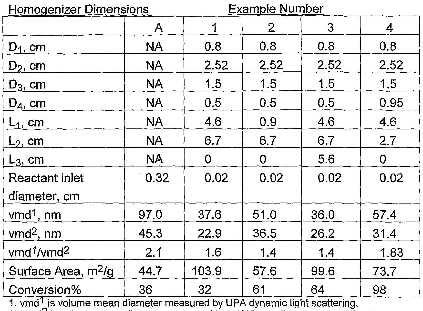
- Figure 7 is an SEM micrograph of the TiO 2 nanoparticles produced under this condition. Table: Summary of Homogenizer Dimension and Particle Properties from Examples
- vmd volume mean diameter measured by SAXS, small angle x-ray diffraction.
- vmd 1 /vmd 2 is the ratio of volume mean diameters measured by each method.
- Example A The effect of the reaction chamber on the size of Ti0 nanoparticles is demonstrated by Example A and Example 1.
- Example 1 With the homogenizer as in Example 1 , the BET surface area increases from 44.7 m 2 /g to 103.9 m 2 /g, suggesting a significant reduction in average primary particle size.
- the volume median diameter decreases from 97 nm to 37.6 nm, suggesting that the dispersible particle size is substantially reduced.
- the size uniformity of the primary particles is demonstrated in Figures 3 and 4. In Figure 3 particles above 100 nm and below 30 nm are both observed, while in Figure 4 the vast majority of the primary particles are in the range of 10-30 nm.
- the reaction chamber can reduce the primary particle size, increase the size uniformity of the primary particles and improve the dispersibility.
- Example 1 The importance of the location of the reactant inlets is demonstrated by Example 1 and 2.
- the BET surface area drops from 103.9 m 2 /g to 57.6 m 2 /g.
- the dispersible volume mean diameter increases from 37.6 nm to 51 nm.
- the increase in particle size is very likely caused by the entrainment of the reactant gas in the flow recirculation that is induced by the high temperature gas entering in the upstream section of the homogenizer.
- Examples 1 and 3 study the effect of the length of the homogenizer after the reaction inlets.
- Example 3 a straight section, 5.6 cm long, is added at the end of the homogenizer.
- the resulting volume median diameter measured by SAXS is increased from 22.9 nm to 26.2 nm.
- Figure 6 the SEM micrograph shows that there is more necking between the primary particles.
- Examples 1 and 4 also demonstrated the impact of the length of the homogenization zone.
- L 2 was reduced from 6.7 to 2.7 cm, the resulting volume particle surface area was decreased from 103.9 m 2 /g to 73.7 m 2 /g, and the dispersible volume mean diameter increased from 37.6 nm to 57.4 nm.
Abstract
Description
Claims
Priority Applications (5)
| Application Number | Priority Date | Filing Date | Title |
|---|---|---|---|
| US10/537,042 US7771666B2 (en) | 2002-12-17 | 2003-12-16 | Method of producing nanoparticles using a evaporation-condensation process with a reaction chamber plasma reactor system |
| JP2004562256A JP2006516220A (en) | 2002-12-17 | 2003-12-16 | Method for producing nanoparticles using evaporative concentration method by reaction chamber plasma reactor system |
| EP03790527A EP1638676A2 (en) | 2002-12-17 | 2003-12-16 | Method of producing nanoparticles using a evaporation-condensation process with a reaction chamber plasma reactor system |
| AU2003293578A AU2003293578A1 (en) | 2002-12-17 | 2003-12-16 | Method of producing nanoparticles using a evaporation-condensation process with a reaction chamber plasma reactor system |
| CA002509516A CA2509516A1 (en) | 2002-12-17 | 2003-12-16 | Method of producing nanoparticles using a evaporation-condensation process with a reaction chamber plasma reactor system |
Applications Claiming Priority (2)
| Application Number | Priority Date | Filing Date | Title |
|---|---|---|---|
| US43415802P | 2002-12-17 | 2002-12-17 | |
| US60/434,158 | 2002-12-17 |
Publications (2)
| Publication Number | Publication Date |
|---|---|
| WO2004056461A2 true WO2004056461A2 (en) | 2004-07-08 |
| WO2004056461A3 WO2004056461A3 (en) | 2007-11-22 |
Family
ID=32681999
Family Applications (1)
| Application Number | Title | Priority Date | Filing Date |
|---|---|---|---|
| PCT/US2003/040246 WO2004056461A2 (en) | 2002-12-17 | 2003-12-16 | Method of producing nanoparticles using a evaporation-condensation process with a reaction chamber plasma reactor system |
Country Status (8)
| Country | Link |
|---|---|
| US (1) | US7771666B2 (en) |
| EP (2) | EP2390000A1 (en) |
| JP (1) | JP2006516220A (en) |
| KR (1) | KR20050085704A (en) |
| CN (1) | CN101262939A (en) |
| AU (1) | AU2003293578A1 (en) |
| CA (1) | CA2509516A1 (en) |
| WO (1) | WO2004056461A2 (en) |
Cited By (13)
| Publication number | Priority date | Publication date | Assignee | Title |
|---|---|---|---|---|
| WO2006079213A1 (en) | 2005-01-28 | 2006-08-03 | Tekna Plasma Systems Inc. | Induction plasma synthesis of nanopowders |
| US7217407B2 (en) | 2003-09-11 | 2007-05-15 | E. I. Du Pont De Nemours And Company | Plasma synthesis of metal oxide nanoparticles |
| WO2007103256A2 (en) * | 2006-03-03 | 2007-09-13 | Battelle Memorial Institute | Method and apparatus for high mass concentration nano particle generation |
| WO2007109906A1 (en) * | 2006-03-29 | 2007-10-04 | Northwest Mettech Corporation | Method and apparatus for nanopowder and micropowder production using axial injection plasma spray |
| WO2008022343A2 (en) | 2006-08-18 | 2008-02-21 | Ppg Industries Ohio, Inc. | Method and apparatus for the production of ultrafine particles and related coating compositions |
| WO2008036712A1 (en) * | 2006-09-22 | 2008-03-27 | Ppg Industries Ohio, Inc. | Methods and apparatus for the production of ultrafine particles |
| EP1657219A3 (en) * | 2004-11-05 | 2009-04-01 | Toda Kogyo Corporation | Nanostructural substance |
| US7572423B2 (en) | 2002-11-26 | 2009-08-11 | Cabot Corporation | Fumed metal oxide particles and process for producing the same |
| US8038971B2 (en) | 2008-09-05 | 2011-10-18 | Cabot Corporation | Fumed silica of controlled aggregate size and processes for manufacturing the same |
| WO2012003029A1 (en) * | 2010-06-28 | 2012-01-05 | Ppg Industries Ohio, Inc. | Production of ultrafine particles in a plasma system having controlled pressure zones |
| CN102423669A (en) * | 2010-08-09 | 2012-04-25 | 塔塔咨询服务有限公司 | System for optimizing and controlling particle size distribution and production of nanoparticles in furnace reactor |
| US8729158B2 (en) | 2008-09-05 | 2014-05-20 | Cabot Corporation | Fumed silica of controlled aggregate size and processes for manufacturing the same |
| US11000868B2 (en) | 2016-09-07 | 2021-05-11 | Alan W. Burgess | High velocity spray torch for spraying internal surfaces |
Families Citing this family (42)
| Publication number | Priority date | Publication date | Assignee | Title |
|---|---|---|---|---|
| CN101076716B (en) * | 2004-10-08 | 2011-04-13 | Sdc材料有限责任公司 | An apparatus for and method of sampling and collecting powders flowing in a gas stream |
| US9180423B2 (en) | 2005-04-19 | 2015-11-10 | SDCmaterials, Inc. | Highly turbulent quench chamber |
| DE102005028463A1 (en) * | 2005-06-17 | 2006-12-28 | Basf Ag | Process for the preparation of nanoparticulate lanthanoid / boron compounds of nanoparticulate lanthanide / boron compounds containing solid mixtures |
| WO2007016418A2 (en) * | 2005-07-29 | 2007-02-08 | The Regents Of The University Of California | A method for online measurement of ultrafine aggregate surface area and volume distributions |
| US8268405B2 (en) * | 2005-08-23 | 2012-09-18 | Uwm Research Foundation, Inc. | Controlled decoration of carbon nanotubes with aerosol nanoparticles |
| US8240190B2 (en) * | 2005-08-23 | 2012-08-14 | Uwm Research Foundation, Inc. | Ambient-temperature gas sensor |
| WO2007083076A1 (en) * | 2006-01-20 | 2007-07-26 | Ineos Europe Limited | Quench tube, apparatus and process for catalytic gas phase reactions |
| KR100801114B1 (en) | 2006-08-01 | 2008-02-05 | 한국원자력연구원 | Manufacturing apparatus of nano-sized powder and method of the same |
| US20080075654A1 (en) * | 2006-09-21 | 2008-03-27 | Jamison Matthew E | Titanium dioxide process |
| US8507401B1 (en) | 2007-10-15 | 2013-08-13 | SDCmaterials, Inc. | Method and system for forming plug and play metal catalysts |
| JP4675398B2 (en) * | 2007-10-17 | 2011-04-20 | 株式会社栗本鐵工所 | Magnetorheological fluid and method for producing magnetorheological fluid |
| USD627900S1 (en) | 2008-05-07 | 2010-11-23 | SDCmaterials, Inc. | Glove box |
| US20100276827A1 (en) * | 2009-04-29 | 2010-11-04 | Kevin Smith | Method for Producing Nanoparticles |
| ITMI20092107A1 (en) | 2009-11-30 | 2011-06-01 | Milano Politecnico | METHOD AND APPARATUS FOR DEPOSITION OF THIN NANOSTRUCTURED LAYERS WITH CONTROLLED MORPHOLOGY AND NANOSTRUCTURE |
| US8557727B2 (en) | 2009-12-15 | 2013-10-15 | SDCmaterials, Inc. | Method of forming a catalyst with inhibited mobility of nano-active material |
| US9149797B2 (en) | 2009-12-15 | 2015-10-06 | SDCmaterials, Inc. | Catalyst production method and system |
| US8652992B2 (en) | 2009-12-15 | 2014-02-18 | SDCmaterials, Inc. | Pinning and affixing nano-active material |
| US8803025B2 (en) | 2009-12-15 | 2014-08-12 | SDCmaterials, Inc. | Non-plugging D.C. plasma gun |
| US9039916B1 (en) | 2009-12-15 | 2015-05-26 | SDCmaterials, Inc. | In situ oxide removal, dispersal and drying for copper copper-oxide |
| US9126191B2 (en) | 2009-12-15 | 2015-09-08 | SDCmaterials, Inc. | Advanced catalysts for automotive applications |
| US8470112B1 (en) | 2009-12-15 | 2013-06-25 | SDCmaterials, Inc. | Workflow for novel composite materials |
| US8545652B1 (en) | 2009-12-15 | 2013-10-01 | SDCmaterials, Inc. | Impact resistant material |
| GB0922552D0 (en) * | 2009-12-23 | 2010-02-10 | Croda Int Plc | Particulate titanium dioxide |
| US8669202B2 (en) | 2011-02-23 | 2014-03-11 | SDCmaterials, Inc. | Wet chemical and plasma methods of forming stable PtPd catalysts |
| FR2975223B1 (en) * | 2011-05-10 | 2016-12-23 | Electricite De France | THERMAL TREATMENT BY INJECTION OF A CALOPORANT GAS. |
| KR101894109B1 (en) * | 2011-05-13 | 2018-08-31 | 프론트라인 바이오에너지, 엘엘씨. | Apparatus and method for optimized acid gas and toxic metal control in gasifier produced gases |
| RU2014110365A (en) | 2011-08-19 | 2015-09-27 | ЭсДиСиМАТИРИАЛЗ, ИНК. | COATED SUBSTRATES FOR USE IN CATALYSIS, CATALYTIC CONVERTERS AND METHODS OF COATING SUBSTRATES WITH OXIDE COATING COMPOSITIONS |
| US20150147257A1 (en) * | 2012-06-05 | 2015-05-28 | Dow Corning Corporation | Fluid capture of nanoparticles |
| US9156025B2 (en) | 2012-11-21 | 2015-10-13 | SDCmaterials, Inc. | Three-way catalytic converter using nanoparticles |
| US9511352B2 (en) | 2012-11-21 | 2016-12-06 | SDCmaterials, Inc. | Three-way catalytic converter using nanoparticles |
| US9586179B2 (en) | 2013-07-25 | 2017-03-07 | SDCmaterials, Inc. | Washcoats and coated substrates for catalytic converters and methods of making and using same |
| US9517448B2 (en) | 2013-10-22 | 2016-12-13 | SDCmaterials, Inc. | Compositions of lean NOx trap (LNT) systems and methods of making and using same |
| CN106061600A (en) | 2013-10-22 | 2016-10-26 | Sdc材料公司 | Catalyst design for heavy-duty diesel combustion engines |
| WO2015143225A1 (en) | 2014-03-21 | 2015-09-24 | SDCmaterials, Inc. | Compositions for passive nox adsorption (pna) systems |
| GB201410639D0 (en) * | 2014-06-13 | 2014-07-30 | Fgv Cambridge Nanosystems Ltd | Apparatus and method for plasma synthesis of graphitic products including graphene |
| US9951420B2 (en) * | 2014-11-10 | 2018-04-24 | Sol Voltaics Ab | Nanowire growth system having nanoparticles aerosol generator |
| CN105148809A (en) * | 2015-09-29 | 2015-12-16 | 泰州市鑫润天冶金保温材料有限公司 | Nanoscale thermal insulation material production device |
| KR101910254B1 (en) * | 2016-12-07 | 2018-10-19 | 한국에너지기술연구원 | Method of Manufacturing Core-Shell Catalyst and Apparatus for Manufacturing the Same |
| CN106824040A (en) * | 2017-01-23 | 2017-06-13 | 昆明冶金研究院 | A kind of high-speed gas reactor and its application method |
| DE102017204488A1 (en) | 2017-03-17 | 2018-09-20 | Technische Universität Berlin | Process for the preparation of monodisperse nanoparticles from a liquid mixture |
| CN109378682B (en) * | 2018-11-19 | 2021-08-27 | 中国科学院大连化学物理研究所 | Device for generating new substance by using laser to bombard target material |
| CN114054766B (en) * | 2021-11-17 | 2023-08-04 | 广东工业大学 | Multi-size nano metal particles and preparation system, preparation method and application thereof |
Family Cites Families (12)
| Publication number | Priority date | Publication date | Assignee | Title |
|---|---|---|---|---|
| NL131050C (en) * | 1958-09-25 | 1900-01-01 | ||
| US3069281A (en) * | 1959-10-26 | 1962-12-18 | Pittsburgh Plate Glass Co | Method of preparing metal oxides |
| GB981183A (en) * | 1960-03-09 | 1965-01-20 | Pittsburgh Plate Glass Co | Production of metal oxides |
| GB1047713A (en) | 1962-07-17 | 1966-11-09 | Thann Fab Prod Chem | Improvements in or relating to the production of finely divided metal oxides |
| US3642442A (en) * | 1964-03-25 | 1972-02-15 | Ppg Industries Inc | Process for preparing pigmentary metal oxide |
| US3586489A (en) * | 1968-08-29 | 1971-06-22 | Titan Gmbh | Device for the manufacture of fine particle size titanium dioxide |
| US5749937A (en) * | 1995-03-14 | 1998-05-12 | Lockheed Idaho Technologies Company | Fast quench reactor and method |
| US5874134A (en) * | 1996-01-29 | 1999-02-23 | Regents Of The University Of Minnesota | Production of nanostructured materials by hypersonic plasma particle deposition |
| US5788738A (en) | 1996-09-03 | 1998-08-04 | Nanomaterials Research Corporation | Method of producing nanoscale powders by quenching of vapors |
| US5851507A (en) | 1996-09-03 | 1998-12-22 | Nanomaterials Research Corporation | Integrated thermal process for the continuous synthesis of nanoscale powders |
| US20020155059A1 (en) * | 2001-04-24 | 2002-10-24 | Tekna Plasma Systems Inc. | Plasma synthesis of titanium dioxide nanopowder and powder doping and surface modification process |
| US20020192138A1 (en) * | 2001-06-19 | 2002-12-19 | Yuill William A. | Process for producing finely divided metal oxides |
-
2003
- 2003-12-16 CA CA002509516A patent/CA2509516A1/en not_active Abandoned
- 2003-12-16 CN CNA2003801066612A patent/CN101262939A/en active Pending
- 2003-12-16 US US10/537,042 patent/US7771666B2/en not_active Expired - Fee Related
- 2003-12-16 EP EP11178898A patent/EP2390000A1/en not_active Withdrawn
- 2003-12-16 AU AU2003293578A patent/AU2003293578A1/en not_active Abandoned
- 2003-12-16 JP JP2004562256A patent/JP2006516220A/en active Pending
- 2003-12-16 WO PCT/US2003/040246 patent/WO2004056461A2/en active Application Filing
- 2003-12-16 EP EP03790527A patent/EP1638676A2/en not_active Ceased
- 2003-12-16 KR KR1020057011065A patent/KR20050085704A/en not_active Application Discontinuation
Non-Patent Citations (1)
| Title |
|---|
| S. BRUNAUER; P. H. EMMETT; E. TELLER, JACS, vol. 60, 1938, pages 309 |
Cited By (24)
| Publication number | Priority date | Publication date | Assignee | Title |
|---|---|---|---|---|
| US7572423B2 (en) | 2002-11-26 | 2009-08-11 | Cabot Corporation | Fumed metal oxide particles and process for producing the same |
| US7217407B2 (en) | 2003-09-11 | 2007-05-15 | E. I. Du Pont De Nemours And Company | Plasma synthesis of metal oxide nanoparticles |
| EP1657219A3 (en) * | 2004-11-05 | 2009-04-01 | Toda Kogyo Corporation | Nanostructural substance |
| EP1843834A4 (en) * | 2005-01-28 | 2008-02-27 | Tekna Plasma Systems Inc | Induction plasma synthesis of nanopowders |
| EP1843834A1 (en) * | 2005-01-28 | 2007-10-17 | Tekna Plasma Systems, Inc. | Induction plasma synthesis of nanopowders |
| US8013269B2 (en) | 2005-01-28 | 2011-09-06 | Tekna Plasma Systems Inc. | Induction plasma synthesis of nanopowders |
| WO2006079213A1 (en) | 2005-01-28 | 2006-08-03 | Tekna Plasma Systems Inc. | Induction plasma synthesis of nanopowders |
| US9845242B2 (en) | 2006-03-03 | 2017-12-19 | Battelle Memorial Institute | Method and apparatus for high mass concentration nano particle generation |
| US10392252B2 (en) | 2006-03-03 | 2019-08-27 | Battelle Memorial Institute | Method and apparatus for high mass concentration nano particle generation |
| WO2007103256A3 (en) * | 2006-03-03 | 2008-02-07 | Battelle Memorial Institute | Method and apparatus for high mass concentration nano particle generation |
| WO2007103256A2 (en) * | 2006-03-03 | 2007-09-13 | Battelle Memorial Institute | Method and apparatus for high mass concentration nano particle generation |
| JP2009531256A (en) * | 2006-03-03 | 2009-09-03 | バッテル メモリアル インスティテュート | Method and apparatus for producing nanoparticles at high mass concentration |
| WO2007109906A1 (en) * | 2006-03-29 | 2007-10-04 | Northwest Mettech Corporation | Method and apparatus for nanopowder and micropowder production using axial injection plasma spray |
| WO2008022343A2 (en) | 2006-08-18 | 2008-02-21 | Ppg Industries Ohio, Inc. | Method and apparatus for the production of ultrafine particles and related coating compositions |
| US7758838B2 (en) | 2006-08-18 | 2010-07-20 | Ppg Industries Ohio, Inc. | Method and apparatus for the production of ultrafine particles and related coating compositions |
| WO2008022343A3 (en) * | 2006-08-18 | 2008-04-17 | Ppg Ind Ohio Inc | Method and apparatus for the production of ultrafine particles and related coating compositions |
| WO2008036712A1 (en) * | 2006-09-22 | 2008-03-27 | Ppg Industries Ohio, Inc. | Methods and apparatus for the production of ultrafine particles |
| US8038971B2 (en) | 2008-09-05 | 2011-10-18 | Cabot Corporation | Fumed silica of controlled aggregate size and processes for manufacturing the same |
| US8729158B2 (en) | 2008-09-05 | 2014-05-20 | Cabot Corporation | Fumed silica of controlled aggregate size and processes for manufacturing the same |
| WO2012003029A1 (en) * | 2010-06-28 | 2012-01-05 | Ppg Industries Ohio, Inc. | Production of ultrafine particles in a plasma system having controlled pressure zones |
| CN102423669A (en) * | 2010-08-09 | 2012-04-25 | 塔塔咨询服务有限公司 | System for optimizing and controlling particle size distribution and production of nanoparticles in furnace reactor |
| CN102423669B (en) * | 2010-08-09 | 2015-09-16 | 塔塔咨询服务有限公司 | Optimize and control the size distribution of nano particle and the system of production in stove reactor |
| US11000868B2 (en) | 2016-09-07 | 2021-05-11 | Alan W. Burgess | High velocity spray torch for spraying internal surfaces |
| US11684936B2 (en) | 2016-09-07 | 2023-06-27 | Alan W. Burgess | High velocity spray torch for spraying internal surfaces |
Also Published As
| Publication number | Publication date |
|---|---|
| AU2003293578A1 (en) | 2004-07-14 |
| AU2003293578A8 (en) | 2004-07-14 |
| US7771666B2 (en) | 2010-08-10 |
| CA2509516A1 (en) | 2004-07-08 |
| EP1638676A2 (en) | 2006-03-29 |
| JP2006516220A (en) | 2006-06-29 |
| WO2004056461A3 (en) | 2007-11-22 |
| KR20050085704A (en) | 2005-08-29 |
| US20060159596A1 (en) | 2006-07-20 |
| EP2390000A1 (en) | 2011-11-30 |
| CN101262939A (en) | 2008-09-10 |
Similar Documents
| Publication | Publication Date | Title |
|---|---|---|
| US7771666B2 (en) | Method of producing nanoparticles using a evaporation-condensation process with a reaction chamber plasma reactor system | |
| US7217407B2 (en) | Plasma synthesis of metal oxide nanoparticles | |
| US20050119398A1 (en) | Plasma synthesis of metal oxide nanoparticles | |
| JP4555742B2 (en) | Equipment for producing metal oxide nanopowder | |
| US8486364B2 (en) | Production of graphenic carbon particles utilizing methane precursor material | |
| KR100991259B1 (en) | Plasma synthesis of metal oxide nanopowder and apparatus therefor | |
| JP5108214B2 (en) | Method for producing metal oxide nanoparticles | |
| US20100314788A1 (en) | Production of Ultrafine Particles in a Plasma System Having Controlled Pressure Zones | |
| KR20040043159A (en) | A process for producing nano-powders and powders of nano-particle loose aggregate | |
| EP1867386A1 (en) | Method for the production of nanoparticles | |
| Dolbec et al. | Nanopowders synthesis at industrial-scale production using the inductively-coupled plasma technology | |
| Hong et al. | Synthesis and characterization of silicon oxide nanoparticles using an atmospheric DC plasma torch | |
| Bulychev | Obtaining nanosized materials in plasma discharge and ultrasonic cavitation | |
| Park et al. | Nanoparticle microreactor: application to synthesis of titania by thermal decomposition of titanium tetraisopropoxide | |
| US8573519B2 (en) | Process for producing nanoscale organic solid particles | |
| He et al. | Overview of the application of flow microreactors in the synthesis of silver nanomaterials | |
| Nitta et al. | Highly Reproducible Synthesis of Hollow Zirconia Particles via Atmospheric-Pressure Plasma Processing with Inkjet Droplets | |
| Zhang et al. | The principle of vapor-phase technics and application in synthesis of M x O y nanomaterials | |
| Castillo et al. | New In-situ Sampling and Analysis of the Production of CeO 2 Powders from Liquid Precursors using a Novel Wet Collection System in a rf Inductively Coupled Thermal Plasma Reactor. Part 1: Reactor System and Sampling Probe | |
| Ishigaki et al. | Size Control of TiO2 Nanoparticles Prepared by Oxidative Pyrolysis of Liquid-Mist Precursors in RF Thermal Plasma | |
| CN117398959A (en) | Device and method for producing micron-sized rutile titanium white | |
| Fujiwara et al. | 4.2 Generation of Particles by Reactions | |
| Marion et al. | Effect of plasma power and precursor size distribution on alumina nanoparticles produced in an inductively coupled plasma (ICP) reactor |
Legal Events
| Date | Code | Title | Description |
|---|---|---|---|
| AK | Designated states |
Kind code of ref document: A2 Designated state(s): AE AG AL AM AT AU AZ BA BB BG BR BY BZ CA CH CN CO CR CU CZ DE DK DM DZ EC EE ES FI GB GD GE GH GM HR HU ID IL IN IS JP KE KG KP KR KZ LC LK LR LS LT LU LV MA MD MG MK MN MW MX MZ NI NO NZ OM PG PH PL PT RO RU SC SD SE SG SK SL SY TJ TM TN TR TT TZ UA UG US UZ VC VN YU ZA ZM ZW |
|
| AL | Designated countries for regional patents |
Kind code of ref document: A2 Designated state(s): GH GM KE LS MW MZ SD SL SZ TZ UG ZM ZW AM AZ BY KG KZ MD RU TJ TM AT BE BG CH CY CZ DE DK EE ES FI FR GB GR HU IE IT LU MC NL PT RO SE SI SK TR BF BJ CF CG CI CM GA GN GQ GW ML MR NE SN TD TG |
|
| 121 | Ep: the epo has been informed by wipo that ep was designated in this application | ||
| WWE | Wipo information: entry into national phase |
Ref document number: 2003790527 Country of ref document: EP |
|
| ENP | Entry into the national phase |
Ref document number: 2006159596 Country of ref document: US Kind code of ref document: A1 |
|
| WWE | Wipo information: entry into national phase |
Ref document number: 10537042 Country of ref document: US |
|
| WWE | Wipo information: entry into national phase |
Ref document number: 2509516 Country of ref document: CA |
|
| WWE | Wipo information: entry into national phase |
Ref document number: 2004562256 Country of ref document: JP Ref document number: 1020057011065 Country of ref document: KR |
|
| WWE | Wipo information: entry into national phase |
Ref document number: 20038A66612 Country of ref document: CN |
|
| WWP | Wipo information: published in national office |
Ref document number: 1020057011065 Country of ref document: KR |
|
| WWP | Wipo information: published in national office |
Ref document number: 2003790527 Country of ref document: EP |
|
| WWP | Wipo information: published in national office |
Ref document number: 10537042 Country of ref document: US |