WO2005053928A2 - Compositions and methods for use in three dimensional model printing - Google Patents

Compositions and methods for use in three dimensional model printing Download PDF

Info

Publication number
WO2005053928A2
WO2005053928A2 PCT/IL2004/001089 IL2004001089W WO2005053928A2 WO 2005053928 A2 WO2005053928 A2 WO 2005053928A2 IL 2004001089 W IL2004001089 W IL 2004001089W WO 2005053928 A2 WO2005053928 A2 WO 2005053928A2
Authority
WO
WIPO (PCT)
Prior art keywords
phase
layers
construction
composition
support
Prior art date
Application number
PCT/IL2004/001089
Other languages
French (fr)
Other versions
WO2005053928A3 (en
Inventor
Eduardo Napadensky
Eliahu M. Kritchman
Avi Cohen
Original Assignee
Objet Geometries Ltd.
Priority date (The priority date is an assumption and is not a legal conclusion. Google has not performed a legal analysis and makes no representation as to the accuracy of the date listed.)
Filing date
Publication date
Application filed by Objet Geometries Ltd. filed Critical Objet Geometries Ltd.
Priority to CN2004800413352A priority Critical patent/CN1926470B/en
Priority to EP04819735A priority patent/EP1695144A4/en
Publication of WO2005053928A2 publication Critical patent/WO2005053928A2/en
Publication of WO2005053928A3 publication Critical patent/WO2005053928A3/en

Links

Classifications

    • BPERFORMING OPERATIONS; TRANSPORTING
    • B29WORKING OF PLASTICS; WORKING OF SUBSTANCES IN A PLASTIC STATE IN GENERAL
    • B29CSHAPING OR JOINING OF PLASTICS; SHAPING OF MATERIAL IN A PLASTIC STATE, NOT OTHERWISE PROVIDED FOR; AFTER-TREATMENT OF THE SHAPED PRODUCTS, e.g. REPAIRING
    • B29C41/00Shaping by coating a mould, core or other substrate, i.e. by depositing material and stripping-off the shaped article; Apparatus therefor
    • B29C41/34Component parts, details or accessories; Auxiliary operations
    • B29C41/48Compensating volume change, e.g. retraction
    • BPERFORMING OPERATIONS; TRANSPORTING
    • B29WORKING OF PLASTICS; WORKING OF SUBSTANCES IN A PLASTIC STATE IN GENERAL
    • B29CSHAPING OR JOINING OF PLASTICS; SHAPING OF MATERIAL IN A PLASTIC STATE, NOT OTHERWISE PROVIDED FOR; AFTER-TREATMENT OF THE SHAPED PRODUCTS, e.g. REPAIRING
    • B29C33/00Moulds or cores; Details thereof or accessories therefor
    • B29C33/44Moulds or cores; Details thereof or accessories therefor with means for, or specially constructed to facilitate, the removal of articles, e.g. of undercut articles
    • B29C33/448Moulds or cores; Details thereof or accessories therefor with means for, or specially constructed to facilitate, the removal of articles, e.g. of undercut articles destructible
    • BPERFORMING OPERATIONS; TRANSPORTING
    • B29WORKING OF PLASTICS; WORKING OF SUBSTANCES IN A PLASTIC STATE IN GENERAL
    • B29CSHAPING OR JOINING OF PLASTICS; SHAPING OF MATERIAL IN A PLASTIC STATE, NOT OTHERWISE PROVIDED FOR; AFTER-TREATMENT OF THE SHAPED PRODUCTS, e.g. REPAIRING
    • B29C41/00Shaping by coating a mould, core or other substrate, i.e. by depositing material and stripping-off the shaped article; Apparatus therefor
    • B29C41/34Component parts, details or accessories; Auxiliary operations
    • B29C41/52Measuring, controlling or regulating
    • BPERFORMING OPERATIONS; TRANSPORTING
    • B29WORKING OF PLASTICS; WORKING OF SUBSTANCES IN A PLASTIC STATE IN GENERAL
    • B29CSHAPING OR JOINING OF PLASTICS; SHAPING OF MATERIAL IN A PLASTIC STATE, NOT OTHERWISE PROVIDED FOR; AFTER-TREATMENT OF THE SHAPED PRODUCTS, e.g. REPAIRING
    • B29C64/00Additive manufacturing, i.e. manufacturing of three-dimensional [3D] objects by additive deposition, additive agglomeration or additive layering, e.g. by 3D printing, stereolithography or selective laser sintering
    • B29C64/10Processes of additive manufacturing
    • B29C64/106Processes of additive manufacturing using only liquids or viscous materials, e.g. depositing a continuous bead of viscous material
    • B29C64/112Processes of additive manufacturing using only liquids or viscous materials, e.g. depositing a continuous bead of viscous material using individual droplets, e.g. from jetting heads
    • BPERFORMING OPERATIONS; TRANSPORTING
    • B29WORKING OF PLASTICS; WORKING OF SUBSTANCES IN A PLASTIC STATE IN GENERAL
    • B29CSHAPING OR JOINING OF PLASTICS; SHAPING OF MATERIAL IN A PLASTIC STATE, NOT OTHERWISE PROVIDED FOR; AFTER-TREATMENT OF THE SHAPED PRODUCTS, e.g. REPAIRING
    • B29C64/00Additive manufacturing, i.e. manufacturing of three-dimensional [3D] objects by additive deposition, additive agglomeration or additive layering, e.g. by 3D printing, stereolithography or selective laser sintering
    • B29C64/40Structures for supporting 3D objects during manufacture and intended to be sacrificed after completion thereof
    • BPERFORMING OPERATIONS; TRANSPORTING
    • B29WORKING OF PLASTICS; WORKING OF SUBSTANCES IN A PLASTIC STATE IN GENERAL
    • B29CSHAPING OR JOINING OF PLASTICS; SHAPING OF MATERIAL IN A PLASTIC STATE, NOT OTHERWISE PROVIDED FOR; AFTER-TREATMENT OF THE SHAPED PRODUCTS, e.g. REPAIRING
    • B29C67/00Shaping techniques not covered by groups B29C39/00 - B29C65/00, B29C70/00 or B29C73/00
    • B29C67/24Shaping techniques not covered by groups B29C39/00 - B29C65/00, B29C70/00 or B29C73/00 characterised by the choice of material
    • BPERFORMING OPERATIONS; TRANSPORTING
    • B33ADDITIVE MANUFACTURING TECHNOLOGY
    • B33YADDITIVE MANUFACTURING, i.e. MANUFACTURING OF THREE-DIMENSIONAL [3-D] OBJECTS BY ADDITIVE DEPOSITION, ADDITIVE AGGLOMERATION OR ADDITIVE LAYERING, e.g. BY 3-D PRINTING, STEREOLITHOGRAPHY OR SELECTIVE LASER SINTERING
    • B33Y10/00Processes of additive manufacturing
    • BPERFORMING OPERATIONS; TRANSPORTING
    • B33ADDITIVE MANUFACTURING TECHNOLOGY
    • B33YADDITIVE MANUFACTURING, i.e. MANUFACTURING OF THREE-DIMENSIONAL [3-D] OBJECTS BY ADDITIVE DEPOSITION, ADDITIVE AGGLOMERATION OR ADDITIVE LAYERING, e.g. BY 3-D PRINTING, STEREOLITHOGRAPHY OR SELECTIVE LASER SINTERING
    • B33Y40/00Auxiliary operations or equipment, e.g. for material handling
    • B33Y40/20Post-treatment, e.g. curing, coating or polishing
    • BPERFORMING OPERATIONS; TRANSPORTING
    • B33ADDITIVE MANUFACTURING TECHNOLOGY
    • B33YADDITIVE MANUFACTURING, i.e. MANUFACTURING OF THREE-DIMENSIONAL [3-D] OBJECTS BY ADDITIVE DEPOSITION, ADDITIVE AGGLOMERATION OR ADDITIVE LAYERING, e.g. BY 3-D PRINTING, STEREOLITHOGRAPHY OR SELECTIVE LASER SINTERING
    • B33Y70/00Materials specially adapted for additive manufacturing
    • BPERFORMING OPERATIONS; TRANSPORTING
    • B33ADDITIVE MANUFACTURING TECHNOLOGY
    • B33YADDITIVE MANUFACTURING, i.e. MANUFACTURING OF THREE-DIMENSIONAL [3-D] OBJECTS BY ADDITIVE DEPOSITION, ADDITIVE AGGLOMERATION OR ADDITIVE LAYERING, e.g. BY 3-D PRINTING, STEREOLITHOGRAPHY OR SELECTIVE LASER SINTERING
    • B33Y80/00Products made by additive manufacturing
    • BPERFORMING OPERATIONS; TRANSPORTING
    • B29WORKING OF PLASTICS; WORKING OF SUBSTANCES IN A PLASTIC STATE IN GENERAL
    • B29CSHAPING OR JOINING OF PLASTICS; SHAPING OF MATERIAL IN A PLASTIC STATE, NOT OTHERWISE PROVIDED FOR; AFTER-TREATMENT OF THE SHAPED PRODUCTS, e.g. REPAIRING
    • B29C37/00Component parts, details, accessories or auxiliary operations, not covered by group B29C33/00 or B29C35/00
    • B29C37/005Compensating volume or shape change during moulding, in general
    • BPERFORMING OPERATIONS; TRANSPORTING
    • B29WORKING OF PLASTICS; WORKING OF SUBSTANCES IN A PLASTIC STATE IN GENERAL
    • B29KINDEXING SCHEME ASSOCIATED WITH SUBCLASSES B29B, B29C OR B29D, RELATING TO MOULDING MATERIALS OR TO MATERIALS FOR MOULDS, REINFORCEMENTS, FILLERS OR PREFORMED PARTS, e.g. INSERTS
    • B29K2063/00Use of EP, i.e. epoxy resins or derivatives thereof, as moulding material
    • BPERFORMING OPERATIONS; TRANSPORTING
    • B29WORKING OF PLASTICS; WORKING OF SUBSTANCES IN A PLASTIC STATE IN GENERAL
    • B29LINDEXING SCHEME ASSOCIATED WITH SUBCLASS B29C, RELATING TO PARTICULAR ARTICLES
    • B29L2009/00Layered products
    • BPERFORMING OPERATIONS; TRANSPORTING
    • B41PRINTING; LINING MACHINES; TYPEWRITERS; STAMPS
    • B41MPRINTING, DUPLICATING, MARKING, OR COPYING PROCESSES; COLOUR PRINTING
    • B41M3/00Printing processes to produce particular kinds of printed work, e.g. patterns
    • B41M3/16Braille printing

Definitions

  • the present invention relates to three-dimensional object building in general and to methods and compositions for use in three-dimensional printing of complex structures in particular.
  • Three-dimensional printing which typically works by building parts in layers, is a process used for the building up of three-dimensional objects.
  • Three-dimensional printing is relatively speedy and flexible, allowing for the production of prototype parts, tooling and rapid manufacturing of three-dimensional complex structures directly from a CAD file, for example.
  • Using three-dimensional printing may enable a manufacturer to obtain a full three-dimensional model of any proposed product before tooling, thereby possibly substantially reducing the cost of tooling and leading to a better synchronization between design and manufacturing. A lower product cost and improved product quality may also be obtained.
  • Using three-dimensional printing also enables the direct manufacturing of full three-dimensional objects, thereby substantially reducing costs and leading to a better synchronization between design, production and consumption (use). A lower product cost and improved product quality may thus also be obtained.
  • the apparatus include a printing head having a plurality of nozzles, a dispenser connected to the printing head for selectively dispensing interface material in layers, and curing means for optionally curing each of the layers deposited.
  • the depth of each deposited layer may be controllable by selectively adjusting the output from each of the plurality of nozzles.
  • embodiments are described including an apparatus and a method for three-dimensional model printing.
  • Some embodiments of this application describe a system and a method for printing complex three-dimensional models by using interface materials having different hardness or elasticity and mixing the interface material from each of the printing heads to control the hardness of the material forming the three-dimensional model.
  • the construction layers of the model may be formed from interface material having a different (harder) modulus of elasticity than the material used to form the release (and support) layers, thereby allowing for the forming of complex shapes.
  • U.S. Patent Nos. 4,303,924, 5,889,084, and 5,270,368 discloses, inter alia, radiation curable compositions for jet-drop printing containing multifunctional ethylenically unsaturated material, monofunctional ethylenically unsaturated material, a reactive synergist, a dye colorant and an oil soluble salt.
  • U.S. Patent No. 4303,924 discloses, inter alia, radiation curable compositions for jet-drop printing containing multifunctional ethylenically unsaturated material, monofunctional ethylenically unsaturated material, a reactive synergist, a dye colorant and an oil soluble salt.
  • 5,889,084 discloses, inter alia, a radiation curable ink composition for ink-jet printing which includes a cationically photoreactive epoxy or vinyl ether monomer or oligomer, a cationic photo-initiator and a coloring agent.
  • U.S. Patent No. 5,270,368 discloses, inter alia, a UV curable ink composition for ink-jet printing including a resin formulation having at least two acrylate components, a photo-initiator and an organic carrier.
  • compositions disclosed in these references are typically formulated for use in ink-jet printing.
  • Compositions for ink-jet printing are typically formulated differently from compositions for building three-dimensional objects, and thus have different properties. For example, high viscosity at room temperature is a desirable property for three-dimensional objects, and thus compositions for building three-dimensional objects are typically designed to have a high viscosity at room temperature.
  • compositions for ink-jet printing are designed to have low viscosity at room temperature in order to function well in the printing process. None of the above-mentioned references disclose compositions that are especially formulated for three-dimensional printing.
  • U.S. Patent No. 5,705,316 discloses compounds having at least one vinyl ether group, which also contain in the molecule at least one other functional group such as an epoxy or an acrylate group; compositions including these compounds; and methods of producing three-dimensional objects using these compositions.
  • the compounds of U.S. 5,705,316 are complex molecules, that are not readily available and thus need to be especially synthesized, which incurs additional time and costs. Thus, there is a need for simple, easily obtainable curable compositions, that are specially formulated to construct a three-dimensional object.
  • Embodiments of the present invention relates to compositions for use in the manufacture of three-dimensional objects.
  • Embodiments of the present invention further relates to compositions for use as a support and/or release material in the manufacture of the three-dimensional objects.
  • Embodiments of the present invention firrther relates to a method for the preparation of a three-dimensional object by three-dimensional printing, and to a three-dimensional object obtained by the method.
  • compositions for use in the manufacture of three-dimensional objects by a method of selective dispensing may include, inter alia, at least one reactive component, at least one photo-initiator, at least one surface-active agent, and at least one stabilizer.
  • the composition has a first viscosity above 50 cps at room temperature, and a second viscosity compatible with ink-jet printers at a second temperature, wherein the second temperature is higher than room temperature.
  • the reactive component is an acrylic component, a molecule having one or more epoxy substituents, a molecule having one or more vinyl ether substituents, vinylcaprolactam, vinylpyrolidone, or any combination thereof.
  • the reactive component is an acrylic component.
  • the acrylic component is an acrylic monomer, an acrylic oligomer, an acrylic crosslinker, or any combination thereof.
  • the reactive component may include, inter alia, an acrylic component and in addition a molecule having one or more epoxy substitutents, a molecule having one or more vinyl ether substituents, vinylcaprolactam, vinylpyrolidone, or any combination thereof.
  • the reactive component may include, inter alia, an acrylic component and vinylcaprolactam. Furthermore, in accordance with an embodiment of the present invention, the reactive component may include, inter alia, a molecule having one or more vinyl ether substitutents.
  • the reactive component may include, inter alia, a molecule having one or more epoxy substituents.
  • the reactive component may include, inter alia, a molecule having one or more vinyl ether substituents, and a molecule having one or more epoxy substitutents.
  • the photo-initiator is a free radical photo-initiator, a cationic photo-initiator, or any combination thereof.
  • the composition further includes at least one pigment and at least one dispersant.
  • the pigment is a white pigment, an organic pigment, an inorganic pigment, a metal pigment or a combination thereof.
  • the composition further includes a dye.
  • the first viscosity of the composition is greater than 80 cps. In one embodiment, the first viscosity is between 80 and 300 cps. In another embodiment, the first viscosity is around 300 cps.
  • the second viscosity of the composition is lower than 20 cps at a second temperature, which is greater than 60°C. Preferably, the second viscosity is between 8 and 15 cps at the second temperature, which is greater than 60°C. In one embodiment, the second viscosity is about 11 cps at a temperature around 85°C.
  • compositions for use as a support and/or release material in the manufacture of three-dimensional objects by a method of selective dispensing may include, inter alia, at least one non-reactive and low toxicity compound, at least one surface-active agent and at least one stabilizer.
  • the composition has a first viscosity above 50 cps at room temperature, and a second viscosity compatible with ink-jet printers at a second temperature, wherein the second temperature is higher than room temperature.
  • the composition may further include, inter alia, at least one reactive component and at least one photo-initiator.
  • the reactive component is at least one of an acrylic component, a molecule having one or more vinyl ether substituents, or the reactive component is a water miscible component that is, after curing, capable of swelling upon exposure to water or to an alkaline or acidic water solution.
  • the reactive component is an acrylic component.
  • the acrylic component is an acrylic oligomer, an acrylic monomer, or a combination thereof.
  • the reactive component may include, inter alia, at least one water miscible component that is, after curing, capable of swelling upon exposure to water or to an alkaline or acidic water solution.
  • the water miscible component is preferably an acrylated urethane oligomer derivative of polyethylene glycol, a partially acrylated polyol oligomer, an acrylated oligomer having hydrophiUic substituents, or any combination thereof.
  • the hydrophilic substituents are preferably acidic substituents, amino substituents, hydroxy substituents, or any combination thereof.
  • the reactive component may include, inter alia, a molecule having one or more vinyl ether substituents.
  • the non-reactive component is polyethylene glycol, methoxy polyethylene glycol, glycerol, ethoxylated polyol, or propylene glycol.
  • the photo-initiator is a free radical photo-initiator, a cationic photo-initiator, or a combination thereof.
  • the first viscosity of the composition is greater than 80 cps. In one embodiment, the first viscosity is between 80 and 300 cps. In another embodiment, the first viscosity is around 200 cps.
  • the second viscosity of the composition is lower than 20 cps at a second temperature, which is greater than 60°C.
  • the second viscosity is between 8 and 15 cps at the second temperature, which is greater than 60°C. In one embodiment, the second viscosity is about
  • a method for preparation of a three-dimensional object by three-dimensional printing includes: dispensing a first interface material from a printing head, the first interface material may include, inter alia, at least one reactive component, at least one photo-initiator, at least one surface-active agent and at least one stabilizer, dispensing a second interface material from the printing head, the second interface material may include, inter alia, at least one non-reactive and low toxicity compound, at least one surface-active agent, and at least one stabilizer,combining the first interface material and the second interface material in pre-determined proportions to produce construction layers for forming the three-dimensional object.
  • the reactive component of the first interface material is an acrylic component, a molecule having one or more epoxy substituents, a molecule having one or more vinyl ether substituents, vinylpyrolidone, vinylcaprolactam, or any combination thereof.
  • the reactive component of the first interface material may include, inter alia, an acrylic component.
  • the acrylic component is an acrylic monomer, an acrylic oligomer, an acrylic crosslinker, or any combination thereof.
  • the reactive component of the first interface material may include, inter alia, an acrylic component and in addition a molecule having one or more epoxy substituents, a molecule having one or more vinyl ether substituents, vinylcaprolactam, vinylpyrolidone, or any combination thereof.
  • the reactive component of the first interface material may include, inter alia, an acrylic component and vinylcaprolactam.
  • the reactive component of the first interface material is a molecule having one or more vinyl ether substituents.
  • the reactive component of the first interface material is a molecule having one or more epoxy substituents.
  • the reactive component of the first interface material may include, inter alia, a molecule having one or more epoxy substituents, and a molecule having one or more vinyl ether substituents.
  • the first interface material may further include, inter alia, at least one pigment and at least one dispersant.
  • the pigment is a white pigment, an organic pigment, an inorganic pigment, a metal pigment or a combination thereof.
  • the first interface material may further include, inter alia, a dye.
  • the method may further include the step of curing the first interface material.
  • the second interface material further may include, inter alia, at least one reactive component and at least one photo-initiator.
  • the reactive component is at least one of an acrylic component, a molecule having one or more vinyl ether substituents, or the reactive component is a water miscible component that is, after curing, capable of swelling upon exposure to water or to an alkaline or acidic water solution.
  • the reactive component is an acrylic component.
  • the acrylic component is an acrylic oligomer, an acrylic monomer, or a combination thereof.
  • the reactive component may include, inter alia, at least one water miscible component that is, after curing, capable of swelling upon exposure to water or to an alkaline or acidic water solution.
  • the water miscible component is preferably an acrylated urethane oligomer derivative of polyethylene glycol, a partially acrylated polyol oligomer, an acrylated oligomer having hydrophiUic substituents, or any combination thereof.
  • the hydrophilic substituents are preferably acidic substituents, amino substituents, hydroxy substituents, or any combination thereof.
  • the reactive component of the second interface material may include, inter alia, a molecule having one or more vinyl ether substituents.
  • the non-reactive component is polyethylene glycol, methoxy polyethylene glycol, glycerol, ethoxylated polyol, or propylene glycol.
  • the photo-initiator of the first interface material and optionally of the second interface material is a free radical photo-initiator, a cationic photo-initiator or any combination thereof.
  • the method may further include the step of irradiating or curing the second interface material.
  • the first interface material and the second interface material have a different modulus of elasticity and a different strength.
  • the first interface material has a higher modulus of elasticity and a higher strength than the second interface material.
  • the method may further include the step of forming a multiplicity of support layers for supporting the object.
  • the support layers are formed by combining the first interface material and the second interface material in pre-determined proportions.
  • the support layers have the same modulus of elasticity and the same strength as the construction layers.
  • the support layers have a lower modulus of elasticity and a lower strength than the construction layers.
  • the method may further include the step of combining the first interface material and the second interface material in pre-determined proportions to form a multiplicity of release layers for releasing the support layers from the object.
  • the release layers have a lower modulus of elasticity and a lower strength than the construction layers and the support layers.
  • the first interface material and the second interface material each have a first viscosity at room temperature, and a second viscosity compatible with ink-jet printers at a second temperature, which may be the same or different, wherein the second temperature is higher than room temperature.
  • a three-dimensional object comprised of a core consisting of a multiplicity of construction layers.
  • the construction layers are prepared by combining pre-determined proportions of the first interface material and the second interface material, described herein.
  • the object may further include a multiplicity of support layers for supporting the core.
  • the support layers are prepared by combining pre-determined proportions of the first interface material and a second interface material.
  • the support layers have the same modulus of elasticity and the same strength as the construction layers.
  • the support layers have a lower modulus of elasticity and a lower strength than the construction layers.
  • the object may further include a multiplicity of release layers for releasing the support layers from the core.
  • the release layers are positioned between the support layers and the construction layers.
  • the release layers are prepared by combining pre-determined proportions of the first interface material and a second interface material.
  • the release layers have a lower modulus of elasticity and a lower strength than the construction layers and the support layers.
  • compositions suitable for building a three-dimensional object may include, inter alia, a curable component, having a functional group, wherein if the functional group is a polymerizable reactive functional group, then the functional group is a (meth)acrylic functional group, a photo-initiator, a surface-active agent and a stabilizer, wherein the composition has a first viscosity of about 50-500 cps at a first temperature, wherein the first temperature is ambient temperature, and a second viscosity lower than 20 cps at a second temperature wherein the second temperature is higher than the first temperature, wherein, after curing, the composition results in a solid form.
  • a curable component having a functional group, wherein if the functional group is a polymerizable reactive functional group, then the functional group is a (meth)acrylic functional group, a photo-initiator, a surface-active agent and a stabilizer, wherein the composition has a first viscosity of about 50-500
  • compositions suitable for support in building a three-dimensional object may include, inter alia, a non-curable component, a curable component, wherein the non-curable component is not reactive with the curable component, a surface-active agent and a stabilizer, wherein the composition has a first viscosity of about 20-500 cps at a first temperature, wherein the first temperature is ambient temperature, and a second viscosity lower than 20 cps at a second temperature wherein the second temperature is higher than the first temperature, wherein, after irradiation, the composition results in a solid, a semi solid or a liquid material.
  • compositions suitable for support in building a three-dimensional object may include, inter alia, a non-curable component, a curable (meth)acrylic component, wherein the non-curable component is not reactive with the curable component, a surface-active agent, a free radical photo-initiator and a stabilizer, wherein the composition has a first viscosity of about 20-500 cps at a first temperature, wherein the first temperature is ambient temperature, and a second viscosity lower than 20 cps at a second temperature wherein the second temperature is higher than the first temperature, wherein, after irradiation, the composition results in a solid, a semi solid or a liquid material.
  • compositions suitable for support in building a tlrree-dimensional object may include, inter alia, at least one non-curable component, at least one curable component including a molecule having one or more epoxy substituents, wherein the non-curable component is not reactive with the curable component, at least one surface-active agent, at least one cationic photo-initiator and at least one stabilizer, wherein the composition has a first viscosity of about 20-500 cps at a first temperature, wherein the first temperature is ambient temperature, and a second viscosity lower than 20 cps at a second temperature wherein the second temperature is higher than the first temperature, wherein, after irradiation, the composition results in a solid, a semi solid or a liquid material.
  • One embodiment of the present invention further provides a method for the preparation of a three-dimensional object by three-dimensional printing, the method may include the steps of dispensing a first composition suitable for building a three-dimensional object from a dispenser, the first composition may include a curable component, having a functional group, wherein if the functional group is a polymerizable reactive functional group, then the functional group is a (meth)acrylic functional group, a photo-initiator, a surface-active agent, and a stabilizer, dispensing a second composition suitable for support in building a three-dimensional object from a dispenser, the second composition may include a non-curable component, a curable component, wherein the non-curable component is not reactive with the curable component, a surface-active agent and a stabilizer, combining the first composition and the second composition in pre-determined proportions to produce a multiplicity of construction layers for forming the three-dimensional object, whereby the first composition is cured resulting in a solid form, and whereby the second composition
  • One embodiment of the present invention further provides a three-dimensional object comprised of a multiplicity of construction layers, wherein the construction layers are prepared by combining pre-determined proportions of a first composition and a second composition according to the invention.
  • compositions for use in the manufacture of three-dimensional objects including compositions for use as a support and/or release material in the manufacture of the three-dimensional objects are provided. There is thus provided, in accordance with an embodiment of the present invention, a composition suitable for building a three-dimensional object.
  • compositions may include, inter alia, a curable component, having a functional group, wherein if the functional group is a polymerizable reactive functional group, then the functional group is a (meth)acrylic functional group, a photo-initiator, a surface-active agent and a stabilizer; wherein said composition has a first viscosity of about 50-500 cps at a first temperature, wherein said first temperature is ambient temperature, and a second viscosity lower than 20 cps at a second temperature wherein said second temperature is higher than said first temperature, wherein, after curing, the composition results in a solid form.
  • a composition suitable for support in building a three-dimensional object wherein if the functional group is a polymerizable reactive functional group, then the functional group is a (meth)acrylic functional group, a photo-initiator, a surface-active agent and a stabilizer; wherein said composition has a first viscosity of about 50-500 cps at
  • compositions may include, inter alia: a non-curable component, a curable component, wherein the non-curable component is not reactive with said curable component, a surface-active agent and a stabilizer, wherein said composition has a first viscosity of about 20-500 cps at a first temperature, wherein said first temperature is ambient temperature, and a second viscosity lower than 20 cps at a second temperature wherein said second temperature is higher than said first temperature, wherein, after irradiation, the composition results in a solid, a semi-solid or liquid material.
  • a method for the preparation of a three-dimensional object by three-dimensional printing is provided in accordance with embodiments of the present invention.
  • Embodiments of the present invention further provide a three-dimensional object prepared according to the methods of the invention.
  • One embodiment of the present invention further provides a method for printing a three-dimensional object, the method may include, inter alia, depositing a first portion of a layer of interface material, by a three-dimensional printing apparatus, and depositing an additional portion of the layer of interface material, the additional portion separated by the first portion by a space, wherein the first portion, the additional portion, and the space are disposed within the same plane.
  • the method may include, inter alia, forming one or more non-continuous segments within the layer of interface material.
  • the method may include, inter alia, filling the space.
  • the method may include, inter alia, depositing the portions in selected areas. In another embodiment, the method may include, inter alia, depositing an additional layer in an additional plane, the additional layer including an additional space, the space and the additional space being displaced when viewed perpendicular to the additional plane.
  • One embodiment of the present invention further provides a method for printing a three-dimensional object, the method may mclude, inter alia, depositing a support construction and depositing a rigid exterior around the support construction, and depositing a release layer around the rigid construction, the release layer being between the rigid exterior and the object.
  • the rigid exterior may have a substantially similar strength and elasticity to the object.
  • the method may include, inter alia, constructing a grid from modeling material, the grid being disposed within the support construction.
  • the method may include, inter alia, removing the support construction as a single unit.
  • the method may include, inter alia, leaving a space for the release layer between the object and the rigid construction.
  • the release layers may remain in a non-solidified state while exposed to radiation. In another embodiment, the release layers may partially solidify upon irradiation. In another embodiment, the release layers may be non-planar.
  • the method may include, inter alia, depositing the release layers at selected locations. In another embodiment, the method may include, inter alia, constructing a plurality of direction indicators, the indicators indicating an order of priority in removal of the support constructions. In another embodiment, the method may include, inter alia, constructing the support construction with a tapered shape in the direction of preferred removal. In another embodiment, the method may include, inter alia, depositing on the support construction support construction indicators. In another embodiment, the support construction may include, inter alia, modeling material, support material and any combination thereof. In another embodiment, the release construction may include, inter alia, modeling material, support material and any combination thereof.
  • One embodiment of the present invention further provides a method of constructing a three dimensional object, the method may include, inter alia, depositing interface material, and constructing for the interface material indicators indicating a preferable removal instruction for at least portions of the interface materials.
  • the method may include, inter alia, displaying the direction indicator on an output device.
  • the indicators may include, inter alia, an order of disassembly.
  • the indicators may include, inter alia, visible printing.
  • One embodiment of the present invention further provides an object printing method, comprising dispensing a plurality of layers of interface material in a predetermined arrangement, such that the outer shell of a printed mold includes predominantly modeling material, and the interior of the printed mold includes predominantly support material.
  • the method may include, inter alia, constructing a grid of modeling material within the support material.
  • the method may include, inter alia, curing the mold.
  • the method may include, inter alia, casting the mold.
  • the method may include, inter alia, heating the mold.
  • interface material may include, inter alia, modeling material, support material and any combination thereof.
  • One embodiment of the present invention further provides an apparatus for printing a three-dimensional object, including, inter alia, a controller to enable depositing a first portion of a layer of interface material, and depositing an additional portion of the layer of interface material, the additional portion separated by the first portion by a space, wherein the first portion, the additional portion, and the space are disposed within the same plane.
  • the controller is to enable formation of one or more non-continuous segments within the layer.
  • the controller is to enable filling the space.
  • the controller is to enable depositing an additional layer in an additional plane, the additional layer including an additional space, the space and the additional space being displaced when viewed perpendicular to the additional plane.
  • the controller is to enable depositing additional displaced layers.
  • One embodiment of the present invention further provides an apparatus for printing a three-dimensional object, including, inter alia, a controller to enable constructing a support construction, constructing a rigid exterior around the support construction, and constructing a release layer around the rigid exterior, the release layer being between the rigid exterior and the object.
  • the rigid exterior may have a substantially similar strength and elasticity to the object.
  • the controller is to enable constructing a grid from modeling material, the grid disposed v ⁇ thin the support construction.
  • the controller is to enable removal of the support construction as a whole.
  • the controller is to enable leaving a space for the release layer between the object and the support construction.
  • one or more release layers may remain in a non-solidified state while exposed to radiation.
  • one or more release layers may partially solidify upon irradiation. In another embodiment, one or more release layers may be non-planar. In another embodiment, one or more release layers may be deposited at selected locations.
  • the controller is to enable constructing a plurality of direction indicators, the indicators indicating an order of priority in removal of the support constructions. In another embodiment, the controller is to enable constructing the support construction with a tapered shape in the direction of preferred removal. In another embodiment, the controller is to enable depositing on the support construction support construction indicators.
  • One embodiment of the present invention further provides an apparatus for printing a three-dimensional object, including, inter alia, a controller to enable constructing an interface layer, and constructing for the interface layer indicators indicating instructions for at least portions of the interface materials.
  • the indicators are to be displayed on an output device.
  • the indicators may include, inter alia, indications of an order of disassembly.
  • the indicators may include, inter alia, visible printing.
  • One embodiment of the present invention further provides an apparatus for printing a three-dimensional object, including, inter alia, a controller to enable dispensing a plurality of layers of interface material in a predetermined arrangement, such that the outer shell of a printed mold includes predominantly modeling material, and the interior of the printed mold includes predominantly support material.
  • the controller is to enable constructing a grid of modeling material within the support material.
  • the controller is to enable curing the mold.
  • interface material may include, inter alia, modeling material, support material and any combination thereof.
  • the present invention provides a pseudo composite material, including, inter alia, a first phase and a second phase, wherein each phase may include, inter alia, an organic compound, wherein each phase comprises a multiplicity of construction layers, wherein the layers are deposited by ink-jet printing, wherein the pseudo composite material exhibits a non-homogeneous three-dimensional structure.
  • the pseudo composite material may fVxrther include, inter alia, one or more phases, wherein each phase comprises a multiplicity of construction layers.
  • the present invention provides a three-dimensional object including, ter alia, a pseudo composite material, wherein the pseudo composite material may include, ter alia, a first phase and a second phase, wherein each phase may include, inter alia, an organic compound, wherein each phase comprises a multiplicity of construction layers, wherein the layers are deposited by ink-jet printing, wherein the pseudo composite material exhibits a non-homogeneous three-dimensional structure.
  • the three-dimensional object may further include, inter alia, one or more phases, wherein each phase comprises a multiplicity of construction layers. In another embodiment, the three-dimensional object may further include, inter alia, one or more phases, wherein each phase comprises a multiplicity of construction layers.
  • the three-dimensional object may further include, inter alia, a multiplicity of support layers for supporting the construction layers of the three-dimensional object.
  • the support layers are any support layers according to the invention.
  • the three-dimensional object may further include, inter alia, a multiplicity of release layers for releasing the support layers, wherein the release layers are positioned between the support layers and the construction layers.
  • the release layers are any release layers according to the invention.
  • the present invention provides a method for the preparation of a pseudo composite material having a non-homogeneous three-dimensional structure
  • the method may include, inter alia, the steps of dispensing a first phase composition from a first dispenser to produce a first phase, wherein the first phase may include, inter alia, an organic compound, dispensing a second phase composition from a second dispenser to produce a second phase, wherein the second phase may include, inter alia, an organic compound, whereby depositing a multiplicity of construction layers, curing or solidifying the first phase composition and the second phase composition, thereby producing a pseudo composite material having a non-homogeneous three-dimensional structure.
  • the method for the preparation of a pseudo composite material having a non-homogeneous three-dimensional structure may further include, inter alia, the step of producing one or more phases, wherein each phase comprises a multiplicity of construction layers.
  • the method for the preparation of a pseudo composite material having a non-homogeneous three-dimensional structure may be used, inter alia, for the preparation of a three-dimensional object.
  • the present invention provides a method for the preparation of a three-dimensional object
  • the method may include, inter alia, the preparation of a pseudo composite material having a non-homogeneous three-dimensional structure
  • the method may include, inter alia, the steps of dispensing a first phase composition from a first dispenser to produce a first phase, wherein the first phase may mclude, ter alia, an organic compound, dispensing a second phase composition from a second dispenser to produce a second phase
  • the second phase may include, inter alia, an organic compound, whereby depositing a multiplicity of construction layers, curing or solidifying the first phase composition and the second phase composition, thereby producing a pseudo composite material having a non-homogeneous three-dimensional structure, thereby producing a three-dimensional object.
  • the method for the preparation of a three-dimensional object may further include, ter alia, the step of producing one or more phases, wherein each phase comprises a multiplicity of construction layers.
  • the method for the preparation of a three-dimensional object may further include, ter alia, the step of producing a multiplicity of support layers for supporting the construction layers of the three-dimensional object.
  • the method for the preparation of a three-dimensional object may further include, inter alia, the step of producing a multiplicity of release layers for releasing the support layers, wherein the release layers are positioned between the support layers and the construction layers.
  • At least one construction layer may include, inter alia, the first phase composition and the second phase composition.
  • curing or solidifying are performed immediately after deposition of one construction layer. In another embodiment, curing or solidifying are performed after deposition of more than one construction layers. In another embodiment, curing or solidifying are performed during deposition of the construction layers. In another embodiment, curing is performed at a controlled temperature. In another embodiment, the temperature is higher than 25°C. In one embodiment, the present invention provides printer for printing a pseudo composite material, including, inter alia a controller to enable producing a first phase and a second phase, wherein each of the first phase and the second phase may include, inter alia, an organic compound, thereby producing a pseudo composite material having a non-homogeneous three-dimensional structure. In another embodiment, the apparatus may further include at least two dispensers.
  • the apparatus may further include at least three dispensers.
  • different phase combinations may be used.
  • the apparatus may be used, ter alia, for the preparation of a three-dimensional object.
  • the first phase is structurally different from the second phase.
  • the first phase is chemically different from the second phase.
  • the first phase exhibits different properties from the second phase.
  • the first phase may be produced by dispensing a first phase composition and the second phase may be produced by dispensing a second phase composition.
  • the first phase composition, the second phase composition or both may include, inter alia, a curable component.
  • the curable component may be electron beam curable, electromagnetic radiation curable, thermo-curable or any combination thereof.
  • the first phase composition, the second phase composition or both may include, inter alia, a first interface material, wherein the first phase composition and the second phase composition are not identical.
  • the first interface material is any first interface material according to the invention.
  • the first phase composition, the second phase composition or both may include, inter alia, a first interface material and a second interface material in a pre-determined proportions, wherein the first phase composition and the second phase composition are not identical.
  • the first and/or second interface materials are any first and/or second interface material according to the invention.
  • the first phase composition, the second phase composition or both may include, inter alia, any composition suitable for building a three-dimensional object according to the invention.
  • the first phase composition, the second phase composition or both may include, inter alia, any composition suitable for support in building a three-dimensional object according to the invention.
  • At least one phase of the pseudo composite material may be a continuous phase. In another embodiment, at least one phase may be a non-continuous phase.
  • the properties of the pseudo composite material may be, inter alia, isotropic properties, un-isotropic properties or a combination thereof.
  • the properties may be, inter alia, mechanical, thermo-mechanical, optical, acoustic, electrical properties or any combination thereof.
  • the mechanical strength of the pseudo composite material along one axis of the material may be higher than the mechanical strength of the material along another axis of the material.
  • the elasticity of the pseudo composite material along one axis of the material may be higher than the elasticity of the material along another axis of the material.
  • the refractive index of the pseudo composite material along one axis of the material may be different than the refractive index of the material along another axis of the material. In another embodiment, the refractive index of the material along one axis may vary.
  • FIG. 1 is a schematic illustration of an embodiment of a three-dimensional printing system
  • FIG. 2 is an elevational view of a three-dimensional object, constructed in accordance with an embodiment of the present invention.
  • FIG. 3 is a schematic illustration of an embodiment of a method for the preparation of three-dimensional object by three-dimensional printing.
  • FIG. 4 A is a schematic illustration of a printing tray and printing object, according to some embodiments of the present invention.
  • FIG. 4B is a schematic illustration of a printed object, according to an embodiment of the present invention.
  • FIGS. 4C-4D are flow chart illustrations of exemplary methods of 3-D printing, according to an embodiment of the present invention.
  • FIG. 5A is a flow chart illustration of exemplary method of printing a support construction for a 3-D object, according to an embodiment of the present invention
  • FIG. 5B is a schematic illustration of a support construction with a rigid outer shell, according to an embodiment of the present invention
  • FIGS. 5C-5D are schematic illustrations of printed objects and associated release layers, according to some embodiments of the present invention.
  • FIG. 5E is a schematic illustration of a printed object with removal indicators, according to an embodiment of the present invention.
  • FIG. 5F is a flow chart illustration of an exemplary method of 3-D printing using indicators, according to an embodiment of the present invention
  • FIG. 5G is a schematic illustration of a support construction with tapered edges, according to an embodiment of the present invention.
  • FIG. 5H is a flow chart illustration of a method of 3-D printing using a support construction with tapered edges, according to an embodiment of the present invention
  • FIG. 6 A is a flow chart illustration of an exemplary method of 3-D printing, according to an embodiment of the present invention.
  • FIG. 6B is a schematic illustration of a support construction with a rigid outer shell and a rigid internal grid, according to an embodiment of the present invention.
  • FIG. 7 is a schematic illustration of a PCM of alternating XY-plane layers according to one embodiment of the present invention: one layer is made of one photopolymer combination, (A and C combination), and the other layer is made of another photopolymer combination (B and C combination);
  • FIG. 8 is a schematic illustration of a PCM of alternating XZ-plane layers according to one embodiment of the present invention: each model construction layer is made of a sequential combination of photopolymer compositions (A and B);
  • FIG. 9 is a schematic illustration of a PCM of an elastomeric continuous phase model with high strength photopolymer reinforcement: the high strength photopolymer
  • non continuous phase, B is constructed in the form of columns, surrounded by an elastomeric photopolymer (continuous phase, A), according to one embodiment of the present invention.
  • FIG. 10 is a schematic illustration of a non-elastomeric continuous phase model: the elastomeric photopolymer may be built as tiny elastic areas (e.g., continuous phase, A), surrounded by non-elastic photopolymer (e.g., non-continuous phase, B), according to one embodiment of the present invention.
  • A continuous phase
  • B non-elastic photopolymer
  • Embodiments of the present invention relates to compositions for use in the manufacture of three-dimensional objects, and to compositions for use as support and/or release material in the manufacture of three-dimensional objects. Embodiments of the present invention further relate to methods method for the preparation of a three-dimensional object by three-dimensional printing, using the above-mentioned compositions, and to a three-dimensional object obtained by the method.
  • the composition for use in the manufacture of the three-dimensional objects may include, inter alia, at least one reactive component, at least one photo-initiator, at least one surface-active agent and at least one stabilizer.
  • the composition may be formulated so as to be compatible for use with ink-jet printers and to have a viscosity at room temperature above 50 cps.
  • the composition for use as a support and/or second interface material in the manufacture of the three-dimensional objects may include, inter alia, at least one non-reactive and low-toxicity component, at least one surface-active agent and at least one stabilizer.
  • the composition may further contain at least one reactive component and at least one photo-initiator.
  • the composition is formulated so as to be compatible for use with ink-jet printers and to have a viscosity at room temperature above 50 cps. The compositions will be described in further detail below.
  • the three-dimensional object according to embodiments of the present invention may be built using, for example, a three-dimensional printing system similar to embodiments of US Patent Application No. 09/412,618, assigned to the Assignees of the present application and incorporated herein by reference, although other suitable three-dimensional printers may be used.
  • a three-dimensional printing system is shown in Fig 1, to which reference is now made.
  • Fig 1 is an illustration of a three-dimensional printing system, generally designated 10, which includes one or more printing heads, referenced 12, and at least two dispensers generally referenced 14 and individually referenced 14a and 14b, containing interface materials, generally referenced 16 and individually referenced 16a and 16b, respectively.
  • Other components, and other sets of components may be used.
  • Printing head 12 has a plurality of ink-jet type nozzles 18, through which interface materials 16a and 16b are jetted.
  • first dispenser 14a is connected to a first set of nozzles, referenced 18a
  • second dispenser 14b is connected to a second set of nozzles, referenced 18b.
  • first interface material 16a is jetted through nozzles 18a
  • second interface material 16b is jetted through nozzles 18b.
  • the three-dimensional printing system may include at least two printing heads. The first printing head is connected to first dispenser 14a and is used to jet first interface material 16a; and the second printing head is connected to second dispenser 14b is used to jet second interface material 16b.
  • the three-dimensional printing system 10 further includes a controller 20, a
  • CAD Computer Aided Design
  • curing unit 24 curing unit 24, and optionally a positioning apparatus 26.
  • the controller 20 is coupled to the CAD system 22, curing unit 24, positioning apparatus 26, printing head 12 and each of the dispensers 14. Control may be affected by other units than shown, such as one or more separate units.
  • the three-dimensional object being produced (28) is built in layers, the depth of each layer typically being controllable by selectively adjusting the output from each of the ink-j et nozzles 18.
  • each dispenser contains interface material having a different hardness
  • first and second interface materials being output from each of the dispensers, respectively, different parts of the three-dimensional object having a different modulus of elasticity and a different strength may be produced.
  • the term “strength” is used as a relative term to indicate the difference in modulus of elasticity among interface materials.
  • the strength of a material may be described, for example, by reference to its modulus of elasticity, which may be defined as: "the ratio of stress to its corresponding strain under given conditions of load, for materials that deform elastically, according to Hooke's law".
  • the first dispenser 14a contains a first interface material 16a, referred to hereinafter as the "first interface material” or “first composition”, and the second dispenser 14b contains a second interface material 16b, referred to hereinafter as the “second interface material” or “second composition”.
  • the first interface material has a different (harder) modulus of elasticity and a greater strength than the second interface material.
  • each layer of materials deposited by the apparatus during the printing process may include a combination of model constructions, support constructions and/or release constructions, according to the requirements of the three-dimensional object being printed.
  • any or all of these may be part or parts comprising a single whole 'layer' printed by the printing apparatus during the printing process.
  • combining the first interface material and the second interface material forms a multiplicity of construction layers, which are defined as the layers constituting the three-dimensional object.
  • Multiplicity refers to a number which is one or greater.
  • combining the first interface material and the second interface material may form a multiplicity of support layers, which are defined as the layers supporting the three-dimensional object, and not constituting the three-dimensional object.
  • first interface material and the second interface material may form a multiplicity of release layers, which are defined as the layers (not constituting the three-dimensional object) for separating the three-dimensional object layer from layers such as the support layers.
  • the release layers typically have a lower modulus of elasticity and a lower strength than the construction layers and the support layers.
  • the support layers are designed substantially exactly as the construction layers, and thus have substantially the same modulus of elasticity and substantially the same strength as the construction layers.
  • the construction layers form a core, and the support layers look like the negative printing of the core.
  • the release layers are positioned between the construction layers and the support layers, and are used to separate the construction layers from the support layers.
  • the support layers have a lower modulus of elasticity and a lower strength than the construction layers.
  • the support layers may be separated from the construction layers by taking advantage of their weaker properties, as will be explained in detail below. Alternatively, the support layers may be separated from the construction layers by positioning release layers between the construction layers and the support layers.
  • Fig 2 is a three-dimensional model of a wineglass, generally referenced 30.
  • This three-dimensional model is printed using the ink-jet type printing system of Fig 1. combining the first interface material and the second interface material to form a multiplicity of construction layers 32 which make up wine glass 30.
  • the construction layers 32 of wineglass 30 need to be supported externally, such as in the area referenced 34. Furthermore, an internal void, referenced 36, needs to be formed during printing. Thus a multiplicity of support layers 38, formed by combining the first interface material and the second interface material, are printed. Furthermore, combination of the first interface material and the second interface material forms a multiplicity of release layers 40.
  • release layers 40 are positioned between construction layers 32 and support layers 38. Generally, release layers 40 have a different (lower) modulus of elasticity than support layers 38 and construction layers 32. Thus release layers 40 may be used to separate support layers 38 from construction layers 32.
  • compositions suitable for use as the first interface and as the second interface material are provided.
  • the first interface material and second interface material according to embodiments of the present invention are especially designed and formulated for building a three-dimensional object using three-dimensional printing. Accordingly, in accordance with an embodiment of the present invention, the first interface material and the second interface material each have a first viscosity at room temperature, and a second viscosity compatible with ink-jet printers at a second temperature, which may be the same or different, wherein the second temperature is higher than room temperature, which is defined as about 20-30°C.
  • the first and the second interface materials are designed to have increased viscosity at room temperature, which is defined as about 20-30°C.
  • the first and second interface material have a viscosity greater than 50 cps at room temperature, In another embodiment, the viscosity may be between 80 and 300 cps. In another embodiment, the first and the second interface material may have a viscosity of around 300 cps at room temperature.
  • the first interface material and the second interface material may have a second viscosity compatible with ink-jet printing, at a second temperature which may be higher than room temperature.
  • a composition compatible with ink-jet printing may have a low viscosity, for example, below 20 cps at the printing temperature, in order to function properly in the printing process.
  • the first interface material and the second interface material upon heating, have a viscosity preferably below 20 cps that may enable the construction of the three-dimensional object under heat.
  • the temperature typically used to build the three-dimensional model is higher than 60°C. In another embodiment, the temperature may be about 85°C.
  • the first and second interface materials may have a viscosity of 8-15 cps at a temperature greater than 60°C. In another embodiment, the first and second interface materials may have a viscosity of 11 cps at a temperature of about 85°C.
  • the first and second interface material in one embodiment may be distinguished from prior art formulations designed for ink-jet printing, which have low viscosity at room temperature, the temperature at which the printing is normally conducted.
  • High viscosity at room temperature is a desirable property for three-dimensional objects, a feature that is lacking in the prior art formulations.
  • other embodiments may have other viscosities.
  • the first interface material (typically, the model material) is a composition suitable for building a three-dimensional object.
  • the composition may be formulated to give, after curing, a solid material.
  • this invention describes a composition that after curing results in a solid material, with mechanical properties that permit the building and handling of that three-dimensional object.
  • this invention provides a composition that upon curing results in a solid elastomer like material, with mechanical properties that permit the building and handling of the three-dimensional object
  • One embodiment of the present invention provides a first interface material may include, inter alia, at least one reactive component, at least one photo-initiator, at least one surface-active agent and at least one stabilizer.
  • a composition suitable for building a three-dimensional object the composition may include, inter alia, a curable component, having a functional group, wherein if the functional group is a polymerizable reactive functional group, then the functional group is a (meth)acrylic functional group, a photo-initiator, a surface-active agent and a stabilizer, wherein the composition has a first viscosity of about 50-500 cps at a first temperature, wherein the first temperature is ambient temperature, and a second viscosity lower than 20 cps at a second temperature wherein the second temperature is higher than the first temperature, wherein, after curing, the composition results in a solid form.
  • the first temperature is a room temperature. In another embodiment, the room temperature is between 20-30°C. In another embodiment, the first temperature is ambient temperature. In another embodiment, ambient temperature is between 10-40°C. In another embodiment, ambient temperature is between 15-35°C. In another embodiment, ambient temperature is between 20-30°C. In one embodiment of the present invention, the second temperature is higher than
  • the second temperature is higher than 50°C. In another embodiment, the second temperature is higher than 60°C. In another embodiment, the second temperature is higher than 70°C.
  • the curable component is a reactive component, which is able to undergo polymerization.
  • the curable component may be a (meth)acrylic monomer, a (meth)acrylic oligomer, a (meth)acrylic crosslinker, or any combination thereof.
  • the curable component may be a combination of a mono-functional monomer and a di-functional oligomer.
  • the mono-functional monomer is a high Glass Transition Temperature mono-functional monomer.
  • the di-functional oligomer is a low Glass Transition Temperature di-functional oligomer.
  • the term Glass transition temperature (Tg) is defined as the temperature at which a polymer changes from hard and brittle to soft and pliable material.
  • the Glass Transition Temperature of the mono-functional monomer may be higher than 60°C.
  • the Glass Transition Temperature of the mono-functional monomer may be higher than 70°C.
  • the Glass Transition Temperature of the mono-functional monomer may be in the range of 70-110°C.
  • the Glass Transition Temperature of the di-fuctional oligomer may be lower than 40°C. In another embodiment, the Glass Transition Temperature of the di-fuctional oligomer may be lower than 30°C. In another embodiment, the Glass Transition Temperature of the di-fuctional oligomer may be in the range of 20-30°C.
  • One embodiment of the present invention provides a composition wherein the Glass Transition Temperature of the mono-functional monomer is higher than 70°C and wherein the Glass Transition Temperature of the di-functional oligomer is lower than 40°C.
  • the composition may include at least 20% of the high Glass Transition Temperature mono-functional monomer. In another embodiment, the composition may include at least 30% of the high Glass Transition Temperature mono-functional monomer. In another embodiment, the composition may include at least 40% of the high Glass Transition Temperature mono-functional monomer. In another embodiment, the composition may include between 20-40% of the high Glass Transition Temperature mono-functional monomer. In another embodiment, the composition may include between 30-60% of the high Glass Transition Temperature mono-functional monomer.
  • the composition may include about 20% of the low Glass Transition Temperature di-functional oligomers. In another embodiment, the composition may include about 40% of the low Glass Transition Temperature di-functional oligomers. In another embodiment, the composition may include between 20-40% of the low Glass Transition Temperature di-functional oligomers. In another embodiment, the composition may include at least 20% of the low Glass Transition Temperature di-functional oligomer. In another embodiment, the composition may include not more than 40%) of the low Glass Transition Temperature di-functional oligomer. In one embodiment of the present invention, the composition may include at least 40% of the high Glass Transition Temperature mono-functional monomers and at least 20% of the low Glass Transition Temperature di-functional oligomer.
  • the composition may include at least 20% of the high Glass Transition Temperature mono-functional monomers and not more than 40% of the low Glass Transition Temperature di-functional oligomer.
  • An acrylic monomer is a functional acrylated molecule which may be, for example, esters of acrylic acid and methacrylic acid. Momoners may be mono-functional or multi-functional (for example, di-, tri-, tetra-functional, and others).
  • An example of an acrylic mono-functional monomer according to an embodiment of the present invention is phenoxyethyl acrylate, marketed by Sartomer under the trade name SR-339.
  • An example of an acrylic di-functional monomer is propoxylated (2) neopentyl glycol diacrylate, marketed by Sartomer under the trade name SR-9003.
  • An acrylic oligomer is a functional acrylated molecule which may be, for example, polyesters of acrylic acid and methacrylic acid.
  • Other examples of acrylic oligomers are the classes of urethane acrylates and urethane methacrylates.
  • Urethane-acrylates are manufactured from aliphatic or aromatic or cycloaliphatic diisocyanates or polyisocyanates and hydroxyl-containing acrylic acid esters.
  • An example is a urethane-acrylate oligomer marketed by Cognis under the trade name Photomer-6010.
  • An acrylic crosslinker is a molecule which may provide enhanced crosslinking density.
  • the composition may further includes, inter alia, a curable component, which is a molecule having one or more epoxy substituents, a molecule having one or more vinyl ether substituents, vinylcaprolactam, vinylpyrolidone, or any combination thereof.
  • the composition may further include, inter alia, vinylcaprolactam.
  • Other curable components may also be used.
  • the first interface material may also include a curable component which is, for example, a molecule having one or more vinyl ether substituents.
  • a curable component which is, for example, a molecule having one or more vinyl ether substituents.
  • the concentration of component that includes a molecule having one or more vinyl ether substituents is in the range of 10-30%. In another embodiment, the concentration is 15-20%. In another embodiment, the concentration is 15%. Of course, other concentrations, and other ranges, can be used. Conventional vinyl ether monomers and oligomers which have at least vinyl ether group are suitable.
  • vinyl ethers examples include ethyl vinyl ether, propyl vinyl ether, isobutyl vinyl ether, cyclohexyl vinyl ether, 2-ethylhexyl vinyl ether, butyl vinyl ether, ethyleneglocol monovinyl ether, diethyleneglycol divinyl ether, butane diol divinyl ether, hexane diol divinyl ether, cyclohexane dimethanol monovinyl ether and the like.
  • An example of a vinyl ether according to an embodiment of the present invention is 1,4 cyclohexane dimethanol divinyl ether, marketed by ISP under the trade name CHVE.
  • the first interface material may also include a curable component which is a molecule having one or more epoxy substituents.
  • a curable component which is a molecule having one or more epoxy substituents.
  • conventional epoxy monomers and oligomers which have at least one oxirane moiety may be used.
  • suitable epoxy containing molecules are displayed in Table 1 below (note other suppliers may be used for suitable materials): Table 1: Examples of epoxy-containing curable component
  • the first interface material may include any combination of an acrylic component as defined herein, a molecule having one or more epoxy substituents as defined herein, a molecule having one or more vinyl ether substituents as defined herein, vinylcaprolactam and vinylpyrolidone.
  • the curable component of the first interface material includes, inter alia, an acrylic monomer, an acrylic oligomer, an acrylic crosslinker and vinylcaprolactam.
  • the curable component includes an acrylic component as defined herein and a molecule having one or more epoxy substituents as defined herein.
  • the curable component of the first interface material includes an acrylic component as defined herein and a molecule having one or more vinyl ether substituents as defined herein.
  • the curable component in the first interface material includes a molecule having one or more vinyl ether substituents as defined herein, and a molecule having one or more epoxy substituents as defined herein.
  • the photo-initiator of the first interface material and of the second interface material may be the same or different, and is a free radical photo-initiator, a cationic photo-initiator, or any combination thereof.
  • the free radical photo-initiator may be any compound that produces a free radical on exposure to radiation such as ultraviolet or visible radiation and thereby initiates a polymerization reaction.
  • suitable photo-initiators include benzophenones (aromatic ketones) such as benzophenone, methyl benzophenone, Michler's ketone and xanthones; acylphosphine oxide type photo-initiators such as 2,4,6-trimethylbenzolydiphenyl phosphine oxide (TMPO), 2,4,6-trimethylbenzoylethoxyphenyl phosphine oxide (TEPO), and bisacylphosphine oxides (BAPO's); benzoins and bezoin alkyl ethers such as benzoin, benzoin methyl ether and benzoin isopropyl ether and the like.
  • photo-initiators examples include alpha-amino ketone, marketed by Ciba Specialties Chemicals Inc. (Ciba) under the trade name Irgacure 907, and bisacylphosphine oxide (BAPO's), marketed by Ciba under the trade name 1-819.
  • the free-radical photo-initiator may be used alone or in combination with a co-initiator.
  • Co-initiators are used with initiators that need a second molecule to produce a radical that is active in the UV-systems.
  • Benzophenone is an example of a photoinitiator that requires a second molecule, such as an amine, to produce a curable radical.
  • benzophenone After absorbing radiation, benzophenone reacts with a ternary amine by hydrogen abstraction, to generate an alpha-amino radical which initiates polymerization of acrylates.
  • a class of co-initiators are kanolamines such as triemylamine, methyldiethanolamine and tiiethanolamine.
  • Suitable cationic photo-initiators may include compounds which form aprotic acids or Bronstead acids upon exposure to ultraviolet and/or visible light sufficient to initiate polymerization.
  • the photo-initiator used may be a single compound, a mixture of two or more active compounds, or a combination of two or more different compounds, i.e. co-initiators.
  • suitable cationic photo-initiators are aryldiazonium salts, diaryliodonium salts, triarylsulphonium salts, triarylselenonium salts and the like.
  • a cationic photo-initiator for the present invention may be a mixture of triarylsolfonium hexafluoroantimonate salts marketed by Union Carbide as UVI-6974.
  • the composition suitable for building a three-dimensional object may further include a curable compound, which is a sulfur-containing component.
  • the sulfur-containing component is beta mercaptopropionate, mercaptoacetate, alkane thiols or any combination thereof.
  • the addition of sulfur-containing components may significantly enhance the composition reactivity. At levels of about 5% of sulfur-containing component a significant reactivity enhancement is achieved.
  • the mechanical properties of the composition may be determined depending on the sulfur-containing component used. The reactivity enhancement achieved by the use of sulfur-containing component, enables the incorporation in the polymerization reaction of non sulfur-conl ining components, which would not easily polymerize otherwise.
  • Molecules having unsaturated double bonds is polymerized in the claimed compositions when it contains an appropriate sulfur-containing component.
  • a basic composition will contain 15% low molecular weight unsaturated molecule, 5% sulfur-containing component, 15% mono-functional monomer, 15% di-functional monomer and the rest other curable components according to the intended photopolymer properties.
  • An example of a sulfur-containing component according to an embodiment of the present invention may be trimethylolpropane tri(3 -mercaptopropionate), manufactured by BRUNO BOCK Chemische Fabrik GMBH & CO. Other suitable substances may be used.
  • the composition suitable for building a three-dimensional object further includes, inter alia, a low molecular weight polymer.
  • a low molecular weight polymer may be Styrene-Butadiene-Methacrylate block copolymers (KRATON D), manufactured by Dow Corning. Other suitable substances may be used.
  • the composition suitable for building a three-dimensional object further includes, inter alia, a filler.
  • a filler is defined as an inert material added to a polymer, a polymer composition or other material to modify their properties and/or to adjust quality of the end products.
  • the filler may be an inorganic particle, for example calcium carbonate, silica and clay. Of course other filler substances may be used.
  • Fillers may be introduced in to polymer compositions in order to reduce shrinkage during polymerization or during cooling, for example to reduce the coefficient of thermal expansion, increase strength, increase thermal stability reduce cost and/ or adopt rheological properties.
  • the use of standard fillers has also some drawbacks such as reduction of elasticity and an increase in viscosity. Additionally, large diameter fillers (>5 micron) are not appropriate for ink-jet applications.
  • Nano-particles fillers are especially useful in applications requiring low viscosity such as ink-jet applications. Compositions containing as much as 30%) nano-particle fillers are feasible, whereas the same concentration of more standard and higher diameter fillers ( ⁇ >1 micron) produce at such concentration viscosities which are too high for ink-jet applications, hi one embodiment of the present invention, the nano-particle filler containing composition is clear.
  • the composition is clear (e.g. transparent) since it contains no visual fillers. In contrast, compositions containing more standard and higher diameter visible fillers ( ⁇ >1 micron), are not clear.
  • the composition optionally may contain pigments.
  • the pigment concentration may be lower than 35%. In another embodiment, the pigment concentration may be lower than 15%.
  • the filler may include particles such as particles having an average diameter of less than 100 nm. In another embodiment, the filler may include particles having a diameter in the range of 10-100 nm. In another embodiment, the filler may include particles having a diameter in the range of 20-80 nm. In another embodiment, the filler may include particles having a diameter in the range of 10-50 nm. In another embodiment, the filler may include particles having a diameter smaller than 10 nm. Examples of fillers that may be used in the composition are HIGHLINK OG (particle size spanning between 9 nm to 50 nm), manufactured by Clariant, and NANOCRYL (particle size below 50 nm), manufactured by Hanse Chemie. Other suitable substances may be used.
  • phase separation may be induced during the radiation curing process of the present method.
  • the phase separation may produce a clear material, which may have improved impact-resistance.
  • This composition upon bending develops micro-cracks, before breaking. These micro-cracks can easily be distinguished due to the whitening of the stress area or stress line.
  • the phase separation results in a non-clear cured material.
  • certain combinations of UV curable components induce phase separation during curing.
  • Such compositions are clear before curing and may be clear, hazy or opaque after curing. Such compositions have an improved impact strength and higher elongation, when compared to similar compositions, which do not show such phase separation.
  • silicon containing oligomers at levels as low as 5%>, may already create a substance which induces such phase separation.
  • An example of a silicon acrylated molecule is Ebecryl 350, manufactured by UCB Chemicals. Of course other substances may be used.
  • composition further includes a phase separation inducing component.
  • the phase separation inducing component is a silicon oligomer.
  • the concentration of the silicon oligomer is at least 5%.
  • phase separation may be induced during curing, resulting in a non-clear cured material.
  • Certain combinations of UV curable composition suffer a phase separation process during curing. Such compositions are clear before curing and hazy to white after curing. Such compositions have an improved impact strength and higher elongation, when compared to similar compositions, which do not suffer from such phase separation.
  • the addition of some silicon containing oligomers, at levels as low as 5%, to the above described composition may create a substance which suffers from such face separation.
  • the first viscosity is about 80-500 cps. In another embodiment, the first viscosity is about 300 cps. Of course, compositions having other viscosities may be used.
  • the second viscosity is lower than 20 cps and wherein the second temperature is higher than 60°C. In another embodiment, the second viscosity is between 10 and 17 cps and wherein the second temperature is higher than 60°C. In another embodiment, the second viscosity is between 10 and 17 cps and wherein the second temperature is about 70-110°C. In another embodiment, the second viscosity is between 12 and 15 cps and wherein the second temperature is about 70-90°C. Of course, compositions having other viscosities may be used.
  • first interface material and the second interface material may be surface-active agents and inhibitors (typically, thermal stabilizers).
  • a surface-active agent may be used to reduce the surface tension of the formulation to the value required for jetting or for printing process, which is typically around 30 dyne/cm.
  • An example of a surface-active agent according to an embodiment of the present invention may be silicone surface additive, marketed by Byk Chemie under the trade name Byk 307.
  • Inhibitors may be employed in the formulations of the first interface material and the second interface material to permit the use of the formulation at high temperature, for example around 85°C, without causing thermal polymerization.
  • the composition may further include, inter alia, at least one pigment and at least one dispersant.
  • the pigment may be a white pigment.
  • the pigment may be an organic pigment.
  • the pigment may be an inorganic pigment.
  • the pigment may be a metal pigment or a combination thereof.
  • the composition may further include, inter alia, a dye.
  • An example of a white pigment according to an embodiment of the present invention may be organic treated titanium dioxide, marketed by Kemira Pigments under the trade name UV TITAN Ml 60 VEG.
  • An example of an organic pigment according to an embodiment of the present invention may be an organic pigment marketed by Elementis Specialities under the trade name Tint Aid PC 9703.
  • Examples of dispersants according to embodiments of the present invention may be dispersants including a copolymer with acidic groups marketed by Byk Chemie under the trade name Disperbyk 110, and a dispersant including a high molecular weight block copolymer with pigment affinic groups, marketed by Byk Chemie under the trade name Disperbyk 163.
  • combinations of white pigments and dyes are used to prepare colored resins.
  • the white pigment may have at least a double task: 1) to impart opacity; and 2) to shield the dye from UV radiation, to prevent bleaching of the resin.
  • the first interface material further includes a dye.
  • the dye may be chosen so as not to interfere with the curing efficiency of the formulation of the first interface material.
  • the dye may be any of a broad class of solvent soluble dyes. Some non-limiting examples are azo dyes which are yellow, orange, brown and red; anthraquinone and triarylmethane dyes which are green and blue; and azine dye which is black.
  • An example of a dye according to an embodiment of the present invention may be Solvent Red 127, marketed by Spectra Colors Corp. under the trade name Spectrasol RED BLG.
  • the first interface material includes the following components: 50% acrylic oligomer(s), 30% acrylic monomer(s), 15% acrylic crosslinker, 2% photoinitiator, surface active agent, pigments, and stabilizers. Of course, other compositions may be used.
  • Non-limiting examples of formulations of the first interface material are provided herein in Tables 2-4, to which reference is now made.
  • Tables 2 and 3 illustrate examples of possible formulations of the first interface material.
  • Table 4 illustrates examples of colored formulations, which include pigments, dispersants and dyes, as defined herein. To any of the examples in Tables 2 and 3 may be added the combination of the colorants of Table 4. The individual substances, suppliers, combinations, etc., are given by way of example only.
  • Table 2 Examples of Characteristic Formulation Components of First Interface Material
  • the formulation of the first interface material is presented in entry No. 14 of Table No. 3.
  • the first interface material includes: an acrylic oligomer, which may be any acrylic oligomer as defined herein, and which may be an urethane acrylate oligomer; an acrylic monomer, which may be any acrylic monomer as defined herein, and which may be phenoxy ethyl acrylate; an acrylic crosslinker, which may be any acrylic crosslinker as defined herein, and which may be trimethylol propane triacrylate; a radical photo-initiator, which may be any radical photo-initiator as defined herein, and which may be alpha-amino ketone; a surface agent, which may be a silicone surface additive; an inhibitor, which may be 4-methoxyphenol; and vinylcaprolactam.
  • an acrylic oligomer which may be any acrylic oligomer as defined herein, and which may be an urethane acrylate oligomer
  • an acrylic monomer which may be any acrylic monomer
  • the second interface material (in one embodiment, the support material) is a composition typically formulated to support the building of a three-dimensional object. In one embodiment of the present invention, the second interface material is formulated to form a release layer to permit a manual easy separation or cleaning of the three-dimensional object from its support.
  • the second interface material may be one of two different principle kinds: 1) a liquid material lacking any curable groups that remains liquid even after irradiation.
  • the liquid is water miscible and is easily washed out by water, or with other material.
  • the liquid is non water-miscible and is easily washed out by water or by a water detergent solution and 2) a solid or semi-solid material that is formulated as a weak curable material.
  • the solid or semi-solid material, when cured, may be capable of swelling in water or in alkaline or acidic water or water detergent solution.
  • the second interface material when cured, may swell and almost break upon exposure to water, or in alkaline or acidic water or water detergent solution, with minimum manual work required. In both cases the second interface material is formulated so as to permit fast, easy and efficient removal of the second interface material and cleaning of the three-dimensional model from its support.
  • the second interface material of the present invention may include, inter alia, at least one non-reactive and low toxicity compound, at least one surface-active agent and at least one stabilizer.
  • compositions suitable for support in building a three-dimensional object may include, inter alia, a non-curable component, a curable component, wherein the non-curable component is not reactive with the curable component, a surface-active agent, and a stabilizer, wherein the composition has a first viscosity of about 20-500 cps at a first temperature, wherein the first temperature is ambient temperature, and a second viscosity lower than 20 cps at a second temperature wherein the second temperature is higher than the first temperature, wherein, after irradiation, the composition results in a semi solid material.
  • compositions having other viscosities may be used.
  • the composition suitable for support in building a three-dimensional object, after irradiation may result in a semi-solid material.
  • the semi-solid material may be gel type material.
  • the composition may result in a liquid material.
  • the composition results in a solid material that is formulated as a weak curable material.
  • upon irradiation the composition results in a material that is capable of swelling in water or in alkaline or acidic water.
  • the second interface material swells and almost breaks upon exposure to water, with minimum manual work required.
  • the second interface material is formulated so as to permit fast, easy and efficient removal of the second interface material and cleaning of the three-dimensional model from its support.
  • the curable component is a reactive component.
  • the reactive component can undergo polymerization.
  • the second interface material is formulated as a curable composition that is capable of solidifying upon curing.
  • the curable components may be similar to those used in the first interface material, but chosen specifically to give a hydrophiUic cured resin, with weak mechanical properties. Thus, upon curing, a solid composition is formed that is weak and can be easily pulverized for example by hand or using water.
  • the curable component may be a (meth)acrylic component.
  • the (meth)acrylic component may be a (meth)acrylic monomer.
  • the (meth)acrylic component may be a (meth)acrylic oligomer.
  • the (meth)acrylic component may be a (meth)acrylic crsosslinker.
  • the (meth)acrylic component may be any combination of a (meth)acrylic monomer, a (meth)acrylic oligomer and a (meth)acrylic crsosslinker.
  • the composition may further include, inter alia, at least one photo-initiator.
  • the photo-initiator may a free radical photo-initiator, a cationic photo-initiator, or any combination thereof.
  • the photo-initiator may be any photo-initiator, as defined above.
  • compositions suitable for support in building a three-dimensional object may include, inter alia, a non-curable component, a curable (meth)acrylic component, wherein the non-curable component is not reactive with the curable component, a surface-active agent, a free radical photo-initiator and a stabilizer, wherein the composition has a first viscosity of about 20-500 cps at a first temperature, wherein the first temperature is ambient temperature, and a second viscosity lower than 20 cps at a second temperature wherein the second temperature is higher than the first temperature, wherein, after irradiation, the composition results in a solid, a semi-solid or a liquid material.
  • the composition may further include, inter alia, water.
  • the composition further includes a water miscible component that is, after irradiation or curing, capable of dissolving or swelling upon exposure to water, to an alkaline or acidic water solution or to water detergent solution.
  • the water miscible component is a (meth)acrylated urethane oligomer derivative of polyethylene glycol, a partially (meth)acrylated polyol oligomer, a (meth)acrylated oligomer having hydrophiUic substituents, polyethylene glycol mono or di (meth)acrylated, acrylamide, Acryloylmorpholine(ACMO) or any combination thereof.
  • the hydrophilic substituents are acidic substituents, amino substituents, hydroxy substituents, ionic substituents or any combination thereof.
  • acrylic components for use in the second interface material according to embodiments of the present invention may be polyethylene glycol monoacrylate, marketed by Laporte under the trade name Bisomer PEA6, polyethylene glycol diacrylate, marketed by Sartomer under the trade name SR-610, methoxypolyethyleneglycole 550 monomethacrylate, and the like.
  • the curable component of the second interface material may be a water miscible component that is, after curing, capable of swelling upon exposure to water or to an alkaline or acidic water solution.
  • Non-limiting examples of water miscible components are an acrylated urethane oligomer derivative of polyethylene glycol - polyethylene glycol urethane diacrylate, a partially acrylated polyol oligomer, an acrylated oligomer having hydrophiUic substituents, or any combination thereof.
  • the hydrophilic substituents are acidic substituents, amino substituents, hydroxy substituents, or any combination thereof.
  • An example of an acrylated monomer with hydrophiUic substituents is betha-carboxyethyl acrylate, which contains acidic substituents.
  • the curable component of the second interface material may also be a molecule having one or more vinyl ether substituents, which may be any of the compounds as defined herein.
  • the concentration of component that includes a molecule having one or more vinyl ether substituents is in the range of 10-30%. In another embodiment, the concentration is 15-20%. In another embodiment, the concentration is 15%). Other concentrations may also be used.
  • An example of vinyl ether for the second interface material is 1,4-cyclohexane dimethanol divinyl ether, marketed by ISP under the trade name CHVE. Other molecules having one or more vinyl ether substituents may be used.
  • the curable component of the second interface material is an acrylic oligomer. In another embodiment, the curable component of the second interface material is a combination of an acrylic component as defined herein and a water miscible component as defined herein. In another embodiment, the curable component of the present invention is a combination of an acrylic component as defined herein and a molecule having one or more vinyl ether substituents, as defined herein. In another embodiment, the curable component of the present invention is a combination of a water miscible component as defined herein, and a molecule having one or more vinyl ether substituents, as defined herein. Other combinations may also be used. In one embodiment of the present invention, the composition further includes, inter alia, a sulfur-containing component. In another embodiment, the sulfur containing component is beta mercaptopropionate, mercaptoacetate, alkane thiols or any combination thereof. The sulfur-containing component may be any sulfur-containing component, as defined above.
  • the non-curable component of the second interface material is a non-curable component.
  • the non-curable component is non-polymerizing component.
  • the non-curable component is a low toxicity compound.
  • the non-curable component is a water miscible one.
  • the non-curable component is a non-water miscible one.
  • the non-curable component is chosen to enhance the water-swelling rate, and to reduce the mechanical strength of the second interface material. High water diffusion rate is desirable in order to minimize the time needed for the water cleaning process of the three-dimensional model.
  • Non-limiting examples of non-curable components according to embodiments of the present invention may be polyethylene glycol marketed by Aldrich under the trade name PEG 400, methoxypolyethylene glycol marketed by Aldrich under the trade name methoxycarbowax 500 and 1000, propylene glycol and paraffin oil. Other examples are ethoxylated polyols and glycerol.
  • the second interface material is formulated as a liquid.
  • the liquid formulation is a non-curable composition that remains liquid even after radiation exposure.
  • the liquid formulation includes non-reactive components and does not include reactive components that are capable upon solidifying upon curing.
  • the material may be water miscible, and may easily be washed out with water.
  • the non-curable component is polyethylene glycol, methoxypolyethylene glycol, glycerol, ethoxylated polyol, propylene glycol or any combination thereof.
  • the non-curable component is a non-water miscible compound.
  • the non-water miscible compound is paraffin oil. Other non-curable substances may be used.
  • compositions suitable for support in building a three-dimensional object may include, inter alia, at least one non-curable component, at least one curable component including, inter alia, a molecule having one or more epoxy substituents, wherein the non-curable component is not reactive with the curable component, at least one surface-active agent, at least one cationic photo-initiator and at least one stabilizer, wherein the composition has a first viscosity of about 20-500 cps at a first temperature, wherein the first temperature is ambient temperature, and a second viscosity lower than 20 cps at a second temperature wherein the second temperature is higher than the first temperature, wherein, after irradiation, the composition results in a semi solid material.
  • the first temperature is a room temperature. In another embodiment, the room temperature is between 20-30°C. In another embodiment, the first temperature is ambient temperature. In another embodiment, ambient temperature is between 10-40°C. In another embodiment, ambient temperature is between 15-35°C. In another embodiment, ambient temperature is between 20-30°C.
  • the second temperature is higher than 40°C. In another embodiment, the second temperature is higher than 50°C. In another embodiment, the second temperature is higher than 60°C. i another embodiment, the second temperature is higher than 70°C.
  • another characteristic of the support upon exposure to water or to an alkaline or acidic water or water detergent solution may be the ability to break down during exposure to water or to an alkaline or acidic water solution.
  • the second interface material is made of hydrophiUic components, during the swelling process, internal forces appear and cause fractures and breakdown of the cured second interface material.
  • the second interface material may be at least partially water-soluble. At least part of the second interface material is may be completely water soluble/miscible. During the removal of the support and/or release layers, the water soluble/miscible components are extracted out with water.
  • the second interface material liberates bubbles upon exposure to water or to an alkaline water or acidic water solution. The bubbles are intended to help in the process of removal of the support and/or release layers from the construction layers.
  • the bubbles may be liberated by a bubble releasing substance (BRS) that is present in the water solution that is used to clean out the three-dimensional object.
  • BVS bubble releasing substance
  • Such a substance may be a carbonate or bicarbonate, for example sodium bicarbonate (SBC).
  • SBC sodium bicarbonate
  • the trigger for the production of CO 2 may be the reaction of the SBC with an acid functionality present in the second interface material.
  • acid functionality may be introduced as part of the second interface material formulation or introduced later, after curing, using an acid water solution.
  • the first step may be to put the three-dimensional object with its support in a water solution containing a SBC, then to place the same object in an acidic solution. The acid will start to decompose the SBC and produces gas (bubbles).
  • the substance that liberates gas is already present in the formulation of the second interface material.
  • the second interface material may contain calcium carbonate as a solid filler.
  • the trigger is the introduction of the second interface material in a water or acidic solution.
  • a BRS is not limited to a sodium bicarbonate or calcium carbonate and an acidic water solution. Other chemical reagents and reactions may be used to achieve the same result - the production of bubbles inside the matrix of the second interface material.
  • the SBC may be any alkaline metal or alkaline earth metal carbonate or bicarbonate.
  • the non-curable component is a non-water miscible compound.
  • the non-water miscible compound is paraffin oil.
  • the composition further includes, inter alia, a fiUer.
  • the filler includes particles having a diameter of less than 1 micron.
  • the composition further includes a low molecular weight polymer.
  • the first viscosity composition suitable for support in building a three-dimensional object is about 30-200 cps.
  • the second viscosity of the composition suitable for support in building a three-dimensional object is lower than 20 cps. In another embodiment, the second viscosity is between 10 and 17 cps. In another embodiment, the second viscosity is between 12 and 16 cps.
  • the first and second interface material may be distinguished from certain prior art formulations designed for ink-jet printing, which may have low viscosity at room temperature, the temperature at which the printing is typically conducted. High viscosity at room temperature may be a desirable property for three-dimensional objects, a feature that may be lacking in the prior art formulations.
  • the composition further includes, inter alia, a component able to produce gas upon exposure to water or to an alkaline or acidic water solution.
  • the component is sodium bicarbonate, calcium bicarbonate or a combination thereof. Other suitable substances may be used.
  • the second interface composition further includes, inter alia, a pigment, a dye or a combination thereof.
  • the pigment is a white pigment, an organic pigment, an inorganic pigment, a metal pigment or a combination thereof. Examples of formulations of the second interface material are provided herein in
  • Tables 5 and 6 display various formulations that are suitable for use as the second interface material. The individual substances, suppliers, combinations, etc., are given by way of example only.
  • Table 5 Examples of Characteristic Formulation Components of Second Interface Material
  • the second interface material includes: a water swelling oligomer, which may be any water swelling oligomer as defined herein, and which may be polyethylene glycol; a non-curable component, which may be any non-curable component as defined herein, and which may be polyethylene glycole; a radical photo-initiator, which may be any radical photo-initiator as defined herein, and which may be alpha-amino ketone; a surface agent, which may be a silicone surface additive; and an inhibitor, which may be 4-methoxyphenol.
  • a water swelling oligomer which may be any water swelling oligomer as defined herein, and which may be polyethylene glycol
  • a non-curable component which may be any non-curable component as defined herein, and which may be polyethylene glycole
  • a radical photo-initiator which may be any radical photo-initiator as defined herein, and which may be alpha-amino ketone
  • a surface agent which may be a silicone surface
  • the second interface material includes: a water swelling oligomer, which may be any water swelling oligomer as defined herein, and which may be polyethylene glycole monoacrylate; a non-curable component, which may be any non-curable component as defined herein, and which may be polyethylene glycole; a radical photo-initiator, which may be any radical photo-initiator as defined herein, and which may be benzophenone; a co-initiator, which may be any co-initiator as defined herein, and which may be triethanolamine; a surface agent, which may be a silicone surface additive; and an inhibitor, which may be 4-methoxyphenol.
  • a water swelling oligomer which may be any water swelling oligomer as defined herein, and which may be polyethylene glycole monoacrylate
  • a non-curable component which may be any non-curable component as defined herein, and which may be polyethylene glycole
  • a radical photo-initiator which may be any radical photo-init
  • the first interface material and the second interface material are suitable for use in, for example, the method for three-dimensional printing which is described in U.S. Patent Application 09/412,618, assigned to the Assignees of the present application and is incorporated herein by reference. Other methods may be used. Briefly, the method according to one embodiment includes: dispensing a first interface material from a printing head; dispensing a second interface material from the printing head; and combining the first interface material and the second interface material in pre-determined proportions to a produce a multiplicity of construction layers for forming the three-dimensional model.
  • the method (Fig. 3) includes dispensing a first composition suitable for building a three-dimensional object from a dispenser (102), dispensing a second composition suitable for support in building a three-dimensional object from a dispenser (104), combining the first composition and the second composition in pre-determined proportions to produce a multiplicity of construction layers for forming the three-dimensional object (106), curing the first composition resulting in a solid form (108), and irradiating or curing second composition resulting in a liquid, a solid or a semi-solid form (110).
  • the method may include other steps or series of steps.
  • One embodiment of the present invention further provides a method for the preparation of a three-dimensional object by three-dimensional printing, the method may include the steps of dispensing a first composition suitable for building a three-dimensional object from a dispenser, the first composition may include, inter alia, a curable component, having a functional group, wherein if the functional group is a polymerizable reactive functional group, then the functional group is a (meth)acry ⁇ ic functional group, a photo-initiator, a surface-active agent; and a stabilizer, dispensing a second composition suitable for support in building a three-dimensional object from a dispenser, the second composition may include a non-curable component, a curable component, wherein the non-curable component is not reactive with the curable component, a surface-active agent and a stabilizer, combining the first composition and the second composition in pre-determined proportions to produce a multiplicity of construction layers for forming the three-dimensional object, whereby the first composition is cured resulting in a solid
  • the method may further include the step of generating data for a pre-determined combination of the first composition and the second composition to produce a multiplicity of support layers for supporting the three-dimensional object.
  • the method may further include the step of generating data for a pre-determined combination of the first composition and the second composition to produce a multiplicity of release layers for releasing the three-dimensional object from the support layers.
  • the first composition and the second composition are dispensed simultaneously. In another embodiment, the first composition and the second composition are dispensed sequentially. In another embodiment, the first composition is dispensed first. In another embodiment, the second composition is dispensed first. In another embodiment, more than one first composition is used. In another embodiment, the more than one second composition is used.
  • the method further includes the step of curing the first interface material.
  • the second interface material includes a curable component
  • the method may further include the step of curing the second interface material.
  • Curing may be carried out for example, as described in U.S. Patent Application 09/412,618.
  • the curing method is by radiation, such as Ultraviolet (UV) and/or Visible (Vis) and/or Infra Red (TR) and/or UV-Vis radiation and/or Electron Beam (EB).
  • UV-Vis radiation such as Ultraviolet (UV) and/or Visible (Vis) and/or Infra Red (TR) and/or UV-Vis radiation and/or Electron Beam (EB).
  • UV-Vis radiation such as UV-Vis radiation.
  • Other suitable curing methods may be used.
  • the first interface material and the second interface material are combined in pre-determined proportions. For example, in order to obtain layers having a higher modulus of elasticity and a higher strength such as the construction layers, a suitable combination that contains mostly the first interface material may be used. Further, in order to obtain layers having a lower modulus of elasticity and a lower strength such as the release layers, a suitable combination that includes mostly the second interface material may be used.
  • a combination that includes 90-100% of the first interface material and 0-10% of the second interface material may be used in order to produce the construction layers and/or the support layers.
  • a combination that includes 0-10% of the first interface material and 90-100% of the second interface material may be used in order to produce the release layers.
  • a combination that includes 30-70%) of the first interface material and 70-30% of the second interface material may be used in order to produce support layers that have a lower modulus of elasticity and a lower strength than the construction layers.
  • a three-dimensional object is produced which is included of a core consisting of a multiplicity of construction layers.
  • the construction layers are formed by combining predetermined proportions of the first interface material and the second interface material.
  • One embodiment of the present invention further provides a three-dimensional object comprised of a multiplicity of construction layers, wherein the construction layers are prepared by combining pre-determined proportions of a first composition and a second composition according to the invention.
  • the three-dimensional object is comprised of a core , consisting of a multiplicity of construction layers, wherein the construction layers are prepared by combining pre-determined proportions of a first composition and a second composition according to the invention.
  • the present invention provides a three-dimensional object including the composition according the invention.
  • the three-dimensional object further includes a multiplicity of support layers for supporting the core.
  • the support layers are prepared by combining pre-determined proportions of the first interface material and the second interface material.
  • the support layers may be designed exactly like to construction layers, or may be designed to be weaker (lower modulus of elasticity) than the construction layers.
  • the three-dimensional object may further include a multiplicity of support layers for supporting the core, wherein the support layers are prepared by combining pre-determined proportions of the first composition and the second composition.
  • the support layers support the construction layers.
  • the support layers have the same strength as the construction layers.
  • the support layers have the same modulus of elasticity as the construction layers, h another embodiment, the support layers have a lower modulus of elasticity and/or a lower strength than the construction layers.
  • the three-dimensional object further includes a multiplicity of release layers for releasing the support layers from the construction layers.
  • the release layers are positioned between the support layers and the construction layers. The release layers are prepared by combining pre-determined proportions of the first interface material and the second interface material.
  • the three-dimensional object may further include a multiplicity of release layers for releasing the support layers from the core, wherein the release layers are positioned between the support layers and the construction layers; wherein the release layers are prepared by combining pre-determined proportions of the first composition and the second composition.
  • the release layers have a lower modulus of elasticity and/or a lower strength than the construction layers and the support layers.
  • Deformation of printed objects may occur during or following 3-D object printing.
  • each layer of an object may be deposited during the X movement(s) of the printing head.
  • a layer may generally be continuous, e.g., material may be jetted selectively but continuously from the printing head nozzles during the course of printing in the X direction, to form a continuous layer of material.
  • a layer is deposited generally in one plane, but in alternate embodiments this need not be the case.
  • a layer may contract as a result of curing and cause to strain to accumulate within the body of the printed object.
  • Fig. 4A and 4B are schematic illustrations of object constructions according to some embodiments of the present invention.
  • Segmentation at least part of each layer 205 may be built in non-continuous segments.
  • segments may in alternate embodiments be contiguous - for example small portions of segments may touch.
  • Each of the segments 210 that may constitute a layer 205 or part of a layer may be separated by gaps or spaces 215 (such gaps or spaces need not completely separate segments).
  • Segments 210 are typically, deposited generally in one plane, but in alternate embodiments this need not be the case.
  • segments 210 may shrink separately upon curing, thereby inducing a reduced stress gradient or zero stress gradient towards the center of layer 205. In this way, the accumulative stress that may produce object deformation and/or 'curl' may be eliminated or reduced.
  • non-continuous layers may be deposited in selected areas that are to be segmented, while continuous layers, for example, may be deposited in areas that may not require segmentation.
  • non-contiguous or substantially non-contiguous segments may be deposited in systems where no shrinkage occurs.
  • Two possible examples of segmentation constructions may be seen with reference to Fig. 4B, which is a view from above a printing tray. Other segmentation patterns and methods may be used.
  • Type "A” may include, for example, segments of object construction 210 surrounded in the X and Y directions by spaces, gaps or areas of non-object construction 215..
  • Type "B" may comprise, for example, segments of object constructions 210 that are joined in the Y-direction but separated by spaces or gaps 215 in the X-direction. Other formations or combinations of formations may be used.
  • the method may include, for example, depositing non-continuous layers of interface material.
  • a segment or portion of a layer of interface material may be deposited.
  • a gap or space may be allocated as a space, and may be left free of deposited material after the previous portion of material was deposited.
  • an additional portion of the layer of interface material may be deposited, for example, after the space of the previous deposit of material, thereby forming a non-continuous layer.
  • the portions may be cured after being deposited.
  • space may be allocated and left free of deposited material between the segments.
  • these spaces which may be between segments or partially between segments, may be filled and/or otherwise compensated for, in order to create, for example, a continuous layer out of the previously segmented layer.
  • Various suitable methods may be used to fill in spaces between segments. For example, such spaces may be filled in, either simultaneously or subsequently, using substantially the same interface material that may be applied in a subsequent movement of printing head 12.
  • the spaces may be filled in using substantially the same material, by applying at least one additional layer slightly offset or displaced from the previous layer, so as to be, for example, deposited in between the lines or spaces of the segments laid in previous layers.
  • a further example may be to fill in the spaces using a substantially different type of material, applied in the same and/or subsequent movement of printing head 12. Subsequent layers may be slightly displaced or shifted, for example, in the X and/or Y-directions.
  • Various types and combinations of types of segments, spaces, and fillings may be used. Any combination of the above steps may be implemented. Further, other steps or series of steps may be used.
  • the material(s) may be jetted non-continuously, for example, in a start/stop/start/stop jetting process, as the printing head moves in the X direction.
  • the printing nozzles may jet material(s) over areas predetermined to be object segments and may cease jetting material over adjacent areas that are predetermined to be spaces In the areas where material has been jetted by the nozzles, a segment may be created. In the areas where material has not been jetted by the nozzles, a space between segments may be created.
  • the layers may be cured subsequent to deposition. However, as the curer, e.g., a source of radiation, may follow the path of the printing head, curing may occur in a sweeping motion, curing material just deposited, in the wake of the printing head. That is, the process may be continuous. Other curing methods may be used.
  • segmentation may use various suitable materials to construct the non-continuous layers, segments, spaces, and/or fillings.
  • segmentation may use any of the materials or combinations of materials described herein, for example any first interface material according to the invention, any second interface material according to the invention, any composition suitable for building a three-dimensional object according to the invention, any composition suitable for supporting a three-dimensional object according to the invention, any combination thereof, or any other appropriate material.
  • apparatuses, methods, and compositions may be provided to build release layers or constructions to enable easy removal of support constructions following printing of 3-dimensional objects.
  • Release layers may be, for example, relatively soft constructions that may be constructed in relatively thin layers between the 3-D object being built and the support constructions layers supporting the object, to help provide relatively clean and easy removal of the support construction from the 3-D object or removal of certain portions of interface material or objects (cured or otherwise) from other portions or objects, after completion of the printing process.
  • the 'width' of release layers may vary between a few microns (e.g., similar to a construction layer in some embodiments) and a few hundreds of microns (e.g., similar to the width of a few construction layers in some embodiments).
  • Fig. 5A is a flowchart illustrating a method for printing a support construction for 3-D objects, according to some embodiments of the present invention.
  • the method may include, for example, at block 31, dispensing interface materials in predetermined amounts and combinations, from at least one dispensing unit 16 of printing apparatus 15, to form a support construction.
  • Layers of the support construction may include a first interface material (e.g., modeling material), a second interface material (e.g., support material) and/or other materials or combinations of materials.
  • the support construction may be constructed from support material alone, or may include modeling material, possibly providing additional strength and/or elasticity to the support construction.
  • the support construction may be surrounded or partially surrounded by a rigid construction, for example, it may be contained within or partially within a rigid shell.
  • the rigid construction may be built, for example, from modeling material, or other suitable material that may be, for example, substantially similar in strength and elasticity to the object.
  • the rigid construction may be built to contain the support construction which itself may contain, for example, elements of modeling material surrounded by support material. In this way a rigid support construction may be formed, which may, for example, provide strong support for a 3-D object.
  • a release construction layer may be constructed around the rigid construction of the support construction, to enable easy separation of the rigid construction from the object which is supported by the rigid construction.
  • the shape of the support construction may be determined according to the shape of the object it supports and therefore the shape of the rigid construction may be the shape of the outer surface of the support construction.
  • the support construction may be separated from the object, for example by slight mechanical force, due to the relatively soft release layer between the rigid object and the rigid support construction.
  • separation may occur due to manual manipulation, using a water, air or other fluid stream, etc.
  • support constructions may be divided into a number of smaller support constructions in order to facilitate their dismantling.
  • Each support construction may be contained within its own rigid support construction.
  • a support construction which may be, for example, of a gel-like consistency after curing (other consistencies, such as relatively solid, may be used), may be filled with different combinations of support material and modeling material, for example, producing a soft bulk material.
  • the soft and possibly weak support construction may be strengthened by combining into the support construction a framework or construction comprised of, for example, modeling material, which is harder.
  • the whole 'support construction' which may include support and modeling materials etc., may be relatively firm and yet still soft.
  • the modeling material may be laid as a 'grid' or 'skeleton' within the support material, to provide added strength to the support construction.
  • a support construction in order to facilitate dismantling of such support constructions from a printed object, may be designed to be dismantled as a single unit or in a number of units after printing is completed.
  • a minimal 'space' may be defined or allocated and left free of deposited materials between the 3-D object to be printed and the object's support construction.
  • This space may include, for example, one or more release construction layers, which may consist, for example, predominantly of support material (optionally with a relatively small element of modeling material), hi one embodiment, release constructions may not solidify or may solidify partially to provide a relatively soft layer or layers of material that may enable easy release from a printed object.
  • the release construction layers may not solidify upon irradiation and may remain in, for example, a viscous liquid state, i.e., may remain in a non-polymerized state.
  • the release construction layers may solidify or at least partially solidify upon irradiation, for example, having soft or semisolid gel-like consistency.
  • Such 'soft' release construction layers may help to remove the support construction after completion of the printing process. Removal of such support construction, which may include relatively hard layers, may be relatively easy to perform, and may be performed using little or minimal force.
  • Fig. 5B is a schematic illustration of a 3-D object support construction 300 with a rigid exterior construction 305, according to some embodiments of the present invention.
  • support material 320 may be surrounded or partially surrounded by a rigid exterior 305.
  • the rigid exterior 305 may be constructed from material that may become rigid upon curing and/or cooling, to form, for example, a shell like exterior.
  • Support material 320 together with rigid exterior 305 may form the 3-D object support construction 300.
  • Support construction 302 may be surrounded or partially surrounded by a relatively soft layer 320, for example, a release layer by, to enable support construction 300 to be easily separated from object 315.
  • release construction may be non-planar.
  • release construction material may not necessarily be deposited as a 'layer', and may be deposited in selected locations in the X-Y directions, for example, on top of a previous layer of interface material (e.g., Z direction).
  • the release construction material that may be deposited between the 3-D object (e.g., the modeling construction) and the adjacent support constructions) may fill the space between the constructions, for example, during each movement of the printing head along the X-Y axes.
  • An example of a conical shaped object (other shapes of objects may be constructed) surrounded by support construction, printed with release construction material as described herein, may be seen with reference to Fig.
  • FIG. 5C which shows a side view of an object 35.
  • the 'release layer' 30 is depicted as a thin line separating the object construction 35 and the support structure 40.
  • Fig. 5D illustrates a view of a 'slice' of the constructed object. Release construction 30 is indicated by a thin line encircling the conical object 35, and separating the object from the surrounding support construction 40. Other release layer dimensions and compositions may be used. Release layers may be used between other sections of interface material, not necessarily designated "object" and "support”.
  • instructions or indications for, for example, handling, construction, or deconstruction of a finished object may be deposited, constructed or printed directly on the interface material forming, for example, the object, support constructions, release constructions, etc.
  • indicators indicating a preferable removal direction or order, or instructions for removal or deconstruction of support constructions may be printed or otherwise deposited on support constructions.
  • System controller 15 may have software or executable code that is programmed with predefined instructions for construction of a 3-D object based on the 3-D data received from a 3-D data source, for example, CAD system 22. Controller may provide, for example, a building plan for an object to be built, which may include, for example, the necessary object construction(s), support construction(s), and/or the release construction(s) between the object and support construction(s). In one embodiment of the present invention controller may enable provision of a set of direction indicators, for example, arrows (e.g., Dl, D2, ... Dn) which may define, for example, the position and direction of placement of the release construction layers, and the 'line' along which the support constructions may be removed after printing.
  • arrows e.g., Dl, D2, ... Dn
  • Such indicators may be provided in the controller software, and may appear, for example, as a diagram which may be viewed on a display apparatus 22, for example, a computer screen or other suitable output device.
  • the various direction indicators may be displayed in different colors, or with different symbols. Raised or depressed printing may be used.
  • the set of Dl, D2... Dn indicators may enable the printing apparatus to construct the object and support constructions etc. in such a way so as to enable a recommended procedure of extraction of elements of the support construction after printing.
  • an order of priority of the arrows or other indicators may be set, e.g., the order of priority of the release directions of the structure, which may be determined by the software.
  • structure removal indicators may be visual, for example, they may be constructed from letters, symbols colors, patterns, or other suitable markings. Indicators may be defined in the X, Y and/or Z-directions. For example, as can be seen with reference to Fig. 5E, one support construction 300 may be beneath an obj ect 315, and one support construction 310 may be penetrating object 315 from the side. Construction 300 may be marked with a direction 325, for example, Dl, meaning that it should be removed first, for example, using an arrow showing the direction of preferred removal for this support construction, (e.g., downwards).
  • Construction 310 may be marked with a direction 330, for example, D2, meaning that it should be removed second, with, for example, an arrow at about a 45-degree angle downwards, indicating the direction of its preferred removal.
  • the angle of removal of D2 indicates the line along which the support may efficiently be removed, and may dictate the angle of the 'break' between two adjacent supports, to help facilitate removal of each support structure.
  • support material 320 e.g., soft material
  • Other suitable marking systems may be used, and the objects shown are for example only - other objects may be built, having other support or other auxiliary constructions.
  • an order or priority of the indicators may be defined, for example, according to the preferred order of removal of the support construction(s).
  • the controller software may, for example, calculate and define the direction indicators and/or order of removal of the support construction(s).
  • the software may define, for example, the release construction layers in such a way that each construction may be removed substantially without interfering with or otherwise disturbing the removal of other support structures, due, for example, to the removal of such constructions) in a pre-determined order of priority. Other removal indicating mechanisms may be used.
  • release layers may be constructed with removal indicators.
  • a support construction 340 may be predefined to have, for example, a tapered shape in respect of the direction of preferred removal.
  • the inner portion of the support construction 350 e.g., closer to the 3-D object
  • the outer portion 355 of support construction 300 may be narrower than the outer portion 355 of support construction 300.
  • a soft layer 360 for example, a release layer, may be constructed between support construction 300 and object 315.
  • a support construction may be predefined to have, for example, a tapered shape in respect to the direction of preferred removal.
  • a support construction with an appropriate tapered shape may be constructed.
  • the outer side or edge of the support structure may be predefined to include features, for example holes and/or protrusions etc., which may assist, for example, in identifying the construction as a support construction which is to be removed after printing.
  • Other mechanisms for enabling simplified removal of support constructions from object constructions may be used. Any combination of the above steps may be implemented. Further, other steps or series of steps may be used.
  • release layers or constructions as described herein may use various suitable materials, such as the materials described herein, for example any combinations of pre-determined proportions of the first interface material and a second interface material according to the invention. Of course other materials and compositions may be applied.
  • apparatuses, methods, and compositions may be provided to, for example, build 3 -dimensional molds for use in, for example, investment casting.
  • a mold may be built and subsequently immersed and cast in a heat-resistant substance, for example, ceramic, or such like, which may harden around the mold to form a cast.
  • the thus-formed cast may be placed in an oven and heated. In most cases, the heating process may increase the solidification of the cast material.
  • the original mold may melt or otherwise liquefy and drain away, leaving only the cast, which may then be used for investment casting.
  • Fig. 6A is a flowchart illustrating a method for printing a 3-D prototype mold, according to some embodiments of the present invention.
  • the method may include, for example, at block 40, dispensing layers of interface material in predetermined amounts from one or more printing heads 12 of printing apparatus 15, for example as is described in US Patent No. 6,259,962, which is assigned to the current assignee, and is incorporated herein by reference.
  • the various combinations of interface materials used to form the inner and outer parts of such a 3-D mold, and their relative amounts, order, and place of dispensing, may be determined by, for example, converting a STL file or any suitable graphic or 3-D build or design file for this purpose by system controller 20 via, for example, CAD system 22.
  • the wall thickness of the shell may range, for example, between 0.5mm to 0.9mm, or may be of any other suitable measurements, depending on the size and shape of the object to be cast.
  • the shell may harden upon curing, for example, to form a solid 'shell' around the non-solid support material filling.
  • the mold may be cast, for example, in a ceramic or any other suitable heat-resistant substance, by placing the cast in a heat source, for example, an oven, and heating the cast.
  • the prototype 3-D mold built by printing system 10 may be burnt and may, for example, dissipate in the oven, leaving only the cast which may subsequently be used for investment casting.
  • the prototype material may be burnt out at a high temperature, which may be, for example, in the range of 1000-1800°F or any other suitable temperature range.
  • a high temperature which may be, for example, in the range of 1000-1800°F or any other suitable temperature range.
  • the mold may be easily burnt away, without swelling, thereby minimizing the risk of causing a break in the cast, and substantially without leaving traces of the prototype material inside the cast. Any combination of the above steps may be implemented. Further, other steps or series of steps may be used.
  • a solid outer shell 400 of such a mold may be comprised, for example, predominantly of a first interface material (e.g., modeling material layers).
  • the interior of such a 3-D object shell may be comprised predominantly of a second interface material 410 (e.g., support construction layers).
  • Such support layers may be, for example, strengthened by constructing a grid 420 of the first interface material within the support construction layer. Embodiments of such grid may substantially be executed as described in US Patent Application No. 10/101,089, assigned to the current assignee and incorporated herein by reference, and the description provided herein.
  • the outer shell and interior elements of printed molds as described herein may use various suitable materials, such as the materials described herein, for example any combinations of pre-determined proportions of the first interface material and a second interface material according to the invention. Of course other materials and compositions may be applied.
  • PCM polycarbonate material
  • PCMs may include, inter alia, multi organic macroscopic phase structure.
  • PCM is a new type of non-homogeneous material.
  • PCM is a material whose structure and novel properties are dictated by the compositions composing it and by the specific combination of compositions and/or composition construction arrangement employed at any given time.
  • conventional composite materials are usually organic polymer materials (organic continuous phase) reinforced by inorganic materials (non-continuous phase), in the form of fibers, particles, or other inorganic materials. Organic reinforcement materials are not very common.
  • the PCM may have specially designed isotropic properties. In another embodiment of the present invention, the PCM may have specially designed non-isotropic properties. PCMs may vary in property between isotropic and non-isotropic properties. In one embodiment of the present invention, PCMs may consist of photopolymers, thermocurable compositions, two-component type reaction compositions, phase change, or any combination thereof. In another embodiment, PCMs may include any composition according to the invention. In one embodiment of the present invention, PCMs may include, inter alia, materials having different mechanical and/or optical and/or acoustic and/or other properties. In one embodiment of the present invention, PCMs may include, tnter alia, materials combined in a number of different combinations.
  • the combination of different materials having different properties would be determined according to the type of PCM desired, e.g., a high tensile strength and a high impact resistance.
  • PCM e.g., a high tensile strength and a high impact resistance.
  • other types of PCMs having other properties may be obtained.
  • the terms “multi”, “multiple” or “multiplicity” refer to a number greater than one.
  • phase as referred to throughout the invention may be a material. In another embodiment, the term phase as referred to throughout the invention may be a dete ⁇ riined sector/region. In another embodiment, the phase may be homogeneous, hi another embodiment, the phase may be homogeneous in structure, composition, properties or any combination thereof. In another embodiment, at least one phase of the PCM is different from at least one other phase of the PCM. In another embodiment, different is different in structure, composition, properties or any combination thereof.
  • the term "photopolymer” as referred to throughout the invention may be a composition comprising components able to be polymerized upon exposure to electron beam, electromagnetic radiation, or both, or may be the polymer resulting from such polymerization.
  • thermocurable as referred to throughout the invention may be a composition comprising components whose rate of polymerization is affected by temperature and time. A rise in temperature typically enhances the rate of polymerization.
  • the term "two-component type reaction composition" as referred to throughout the invention may be a polymerization reaction that requires the participation of at least two different chemical functional groups.
  • a non-limiting example of such reaction may be the condensation reaction.
  • phase change as referred to throughout the invention may be a the solidification of a particular composition upon reduction of temperature.
  • a non-limiting example may be the crystallization process of a wax.
  • a non-homogeneous material is a material that includes at least two phases.
  • the present invention provides a pseudo composite material, including, inter alia, a first phase and a second phase, wherein each phase may include, inter alia, an organic compound, wherein each phase may include a multiplicity of construction layers, wherein the layers were deposited by ink-jet printing, wherein the pseudo composite material exhibits non-homogeneous three-dimensional structure.
  • the pseudo composite material may further include, inter alia, one or more phases, wherein each phase may include a multiplicity of construction layers.
  • the present invention provides a three-dimensional object including, inter alia, a pseudo composite material, wherein the pseudo composite material may include, inter alia, a first phase and a second phase, wherein each phase may include, ter alia, an organic compound, wherein each phase may include a multiplicity of construction layers, wherein the layers were deposited by ink-jet printing, wherein the pseudo composite material exhibits non-homogeneous three-dimensional structure.
  • the three-dimensional object may further include, inter alia, one or more phases, wherein each phase may include a multiplicity of construction layers.
  • the three-dimensional object may further include, inter alia, one or more phases, wherein each phase may include a multiplicity of construction layers.
  • the three-dimensional object may further include, inter alia, a multiplicity of support layers for supporting the construction layers of the three-dimensional object.
  • the support layers are any support layers according to the invention.
  • the three-dimensional object may further include, inter alia, a multiplicity of release layers for releasing the support layers, wherein the release layers are positioned between the support layers and the construction layers.
  • the release layers are any release layers according to the invention.
  • the non-homogeneous three-dimensional structure may include, inter alia, sectors/regions of a first phase and sectors/regions of a second phase.
  • the first phase is structurally different from the second phase, hi another embodiment, the first phase is chemically different from the second phase. In another embodiment, the first phase exhibits different properties from the second phase.
  • the first phase may be produced by dispensing a first phase composition and the second phase may be produced by dispensing a second phase composition.
  • phase composition may be any material or combination of materials that are liquid at the deposition temperature and may be dispensed by an ink-jet printing apparatus to form a construction layer.
  • the phase composition may include, inter alia, any interface material according to the invention.
  • any phase according to the invention may be produced by dispensing a phase composition.
  • the curable component may be, for example, electron beam (EB) curable.
  • the curable component may be electromagnetic radiation curable.
  • the electromagnetic radiation curable component may be ultra violet (UV) curable.
  • the electromagnetic radiation curable component may be visible (Vis) curable.
  • the electromagnetic radiation curable component may be infra red (IR) curable.
  • the curable component may be thermo-curable.
  • Other types of curable components may be used.
  • the composition may be two component type reaction compositions.
  • the composition may be phase change.
  • the composition may be any combination of the above mentioned components.
  • the first phase composition, the second phase composition or both may include, inter alia, a curable component.
  • the curable component may be electron beam curable, electromagnetic radiation curable, thermo-curable or any combination thereof.
  • the first phase composition, the second phase composition or both may include, inter alia, a first interface material, wherein the first phase composition and the second phase composition are not identical.
  • the first interface material is any first interface material according to the invention.
  • the first phase composition, the second phase composition or both may include, inter alia, a first interface material and a second interface material in a pre-determined proportions, wherein the first phase composition and the second phase composition are not identical.
  • the first and or second interface materials are any first and/or second interface material according to the invention.
  • the first phase composition, the second phase composition or both may include, inter alia, any composition suitable for building a three-dimensional object according to the invention.
  • the first phase composition, the second phase composition or both may include, inter alia, any composition suitable for support in building a three-dimensional object according to the invention.
  • the phase composition may include, mter alia, a curable component.
  • the phase composition may include, inter alia, a first interface material.
  • the first interface material is any first interface material according to the invention.
  • the phase composition may include, inter alia, a first interface material and a second interface material in a pre-determined proportions.
  • the first and/or second interface materials are any first and/or second interface material according to the invention.
  • the phase composition may include, inter alia, any composition suitable for building a three-dimensional object according to the invention.
  • the phase composition may further include, inter alia, any composition suitable for supporting a three-dimensional object according to the invention.
  • At least one phase of the pseudo composite material may be a continuous phase. In another embodiment, at least one phase may be a non-continuous phase.
  • the properties of the pseudo composite material may be, ter alia, isotropic properties, un-isotropic properties or a combination thereof. In another embodiment, the properties may be, inter alia, mechanical, thermo-mechanical, optical, acoustic, electrical properties or any combination thereof.
  • the mechanical strength of the pseudo composite material along one axis of the material may be higher than the mechanical strength of the material along another axis of the material.
  • the elasticity of the pseudo composite material along one axis of the material may be higher than the elasticity of the material along another axis of the material.
  • the refractive index of the pseudo composite material along one axis of the material may be different than the refractive index of the material along another axis of the material.
  • the refractive index of the material along one axis may vary.
  • the PCM may include, inter alia, at least two photopolymers.
  • the PCM may consist of multiple materials.
  • the materials may have multiple properties and/or multiple colors, and may have specially designed un-isotropic mechanical and/or optical and/or acoustic and/or other properties as well as improved thermo-mechanical properties.
  • the PCM may have gradient properties.
  • PCM structure is pre-designed and may vary according to its intended use, varying between isotropic and non-isotropic, according to the structure and the type of materials comprising it.
  • a PCM may be rigid in one bending axis and flexible in another
  • a PCM may possess rare combinations of properties such as high impact strength and high Heat deflection temperature (HDT)
  • HDT Heat deflection temperature
  • a PCM may have "gradient" properties, i.e., a single piece of material may for example be flexible on one side or extreme and rigid on another side and between these two sides or extremes, the flexible material gradually and smoothly becomes less flexible and more rigid until it has become rigid, showing the existence of a gradient in properties such as strength, modulus and/or elasticity from one side of the object to the other.
  • the gradient properties are not limited to mechanical properties. Other gradient properties, e.g., optical, acoustical and electrical properties are also contemplated by this invention.
  • the PCM structure is pre-designed according to the intended use of the PCM.
  • the mechanical properties include, inter alia, impact strength, elasticity, strength, modulus, etc.
  • the thermo-mechanical properties include, mter alia, Heat Deflection Temperature, coefficient of thermal expansion, etc.
  • the acoustical properties include, inter alia, Absorbance, reflection, transmission of sound waves, internal energy dissipation (damping) etc.
  • the optical properties include, ter alia, refractive index, attenuation, light absorption, light scatter.
  • the electrical properties include, ter alia, dielectric constant, conductivity, etc.
  • the acoustic properties may include, inter alia, absorption and transmission.
  • absorption is the amount of sound that a material can "soak-up" (i.e., the sound energy dissipating into heat energy through viscous friction).
  • porous materials such as open-cell foam may be used as absorbers.
  • transmission describes the amount of sound that passes through a material. Non-transmissive materials are needed to contain sound within a space, or isolate one space from another, such as between a studio and control room. In another embodiment, heavy, solid, limp, airtight materials may be used for preventing sound transmission.
  • the optical properties may include, inter alia, refractive index, attenuation and absorption.
  • refractive index indicates the extent to which a light beam is deflected when passing from vacuum into a given substance.
  • attenuation of the radiant flux occurs when light is passed through a clear medium. If light of suitable wavelength is passed through a sample, part of the energy is transmitted to the molecules sample. As a result, the emergent beam has less energy than the incident beam.
  • the amount of light absorbed generally follows the Lambert-Beer Law and is therefore proportional to the number of absorbing molecules and the path length traversed.
  • the mechanical properties may include, ter alia, those properties of a material that are associated with elastic and inelastic reaction when force is applied, or that involve the relationship between stress and strain; for example, modulus of elasticity, tensile strength, endurance limit.
  • the term macroscopic phase structure refers to phases composing the PCM which are present in agglomerates the physical dimensions of which are macroscopic.
  • the dimensions of the agglomerates are higher than 100 micron in at least one of it is axis diameter.
  • the agglomerates are at least as large as the volume of one droplet.
  • the agglomerates are around 80 nano-gram.
  • the PCM phase structure refers to the specific combination between the different phases which compose it.
  • the PMC phase structure refers to the specific three-dimensional structure formed by the solidification and/or curing of the multiplicity of construction layers, wherein the construction layers are made of the different phase compositions, used to build the PCM.
  • the combination of two or more different compositions with different properties would be determined according to the type of PCM desired to be obtained from the compositions, for example, a strong, solid material with flexibility. Of course, other types of PCMs having other properties may be obtained.
  • multiple, different compositions are combined in different ways in order to obtain a single material with desired properties.
  • the properties are varying along a desired axis.
  • the resulting material is a PCM.
  • a PCM may include combinations designed for use in building model construction layers. In another embodiment, a PCM may include combinations designed for use in building support construction layers. In another embodiment, a PCM may include combinations designed to build release construction layers. In another embodiment, a PCM may include first interface material according to the invention. In another embodiment, a PCM may include second interface material according to the invention.
  • a PCM may be designed to produce a bulk material with pre-designed properties, such as herein described.
  • Non-limiting examples of PCMs comprised of three compositions (A, B, C) which are model-construction layer structures are provided herein: l.
  • a PCM of alternating XY-plane layers one layer is made of one photopolymer combination, (e.g., an A and C combination), and the other layer is made of another photopolymer combination (e.g., a B and C combination) (Fig 7).
  • a PCM of alternating XZ-plane layers each model construction layer is made of a sequential combination of photopolymer compositions (e.g., A and B) (Fig 8).
  • a PCM of an elastomeric continuous phase model with high strength photopolymer reinforcement the high strength photopolymer (for example, a B non continuous phase) is constructed in the form of columns, surrounded by an elastomeric photopolymer (for example, an A continuous phase) (Fig 9).
  • a PCM of a non-elastomeric continuous phase model the elastomeric photopolymer is built as tiny elastic areas (for example using A continuous phase), surrounded by non-elastic photopolymer (for example, B non continuous phase) (Fig 10).
  • a PCM may combine outstanding high-impact strength and relatively high HDT (heat distortion temperature).
  • the materials and methods of the invention are implemented to build a three-dimensional object with a very low curl distortion.
  • the model construction layers are made of non-continuous segments of a first composition (for example, photopolymer A), where the gaps between the segments are filled with the same composition type, after at least partial curing of the non-continuous segments.
  • the model construction layers are made of non-continuous segments of a first composition (for example, photopolymer
  • composition A is a photopolymer elastomer composition including SR 9036 (27%), Cl 1039 (28%), CN131 (15%), SR 506 (22%), Ph 3015 (7%) and 1-819 (1%).
  • composition C is any support composition according to table 6.
  • composition B is a rigid model, as disclosed in Tables 3 and 4.
  • Another embodiment of the present invention provides a printer for producing" a complete three-dimensional object.
  • a rapid prototyping (RP) apparatus for selective deposition of materials may be employed, comprising at least 3 sets of material dispensers (preferably, at least 3 sets of ink-jet printing heads), is used to build a three dimensional object.
  • Each set of material dispensers and/or ink-jet printing heads may comprise one or more dispensers and/or ink-jet printing heads.
  • each set of material dispensers and/or ink-jet printing heads dispenses a different composition. Other numbers of printing heads and materials may be used.
  • 3 sets of ink-jet printing heads may jet or dispense 3 type of materials, denoted herein as compositions A, B, and C, respectively, where "A” develops type A properties, “B” develops type B properties and “C” develops type C properties.
  • A” after curing may develop elastomeric type properties
  • B” after curing may develop high strength non-elastomeric type properties
  • C after curing may develop only very weak mechanical strength properties, such as described herein as the "second interface material”.
  • other compositions may also be applied.
  • compositions of A, B and C may be used to build model construction layers, other compositions of A, B and C may be used to build support construction layers and yet other compositions of A, B and C may be used to build release construction layers.
  • compositions A and B may be used to build model construction layers
  • compositions B and C may be used to build support construction layers
  • composition C may be used to build release construction layers.
  • the present invention provides a printer for printing a pseudo composite material, including, inter alia a controller to enable producing a first phase and a second phase, wherein the first phase and the second phase may include, inter alia, an organic compound, thereby producing a pseudo composite material having a non-homogeneous three-dimensional structure.
  • the apparatus may further include at least two dispensers.
  • the apparatus may further include at least three dispensers.
  • different phase combinations may be used.
  • the apparatus may be used, inter ⁇ li ⁇ , for the preparation of a three-dimensional object.
  • the methods described permit the production of PCM for further processing (such as bulk engineering materials). According to another embodiment, the methods of the present invention enable the production of a complete three-dimensional object.
  • a specific PCM structure comprised of different and multiple, pre-selected compositions is designed. According to the thus designed PCM structure, a number of one or two or more different types of compositions are selectively dispensed to form a layer.
  • the present invention provides a method for the preparation of a pseudo composite material having a non-homogeneous three-dimensional structure
  • the method may include, inter alia, the steps of dispensing a first phase composition from a first dispenser to produce a first phase, wherein the first phase may include, inter alia, an organic compound, dispensing a second phase composition from a second dispenser to produce a second phase, wherein the second phase may include, inter alia, an organic compound, whereby depositing a multiplicity of construction layers, curing or solidifying the first phase composition and the second phase composition, thereby producing a pseudo composite material having a non-homogeneous three-dimensional structure.
  • the method for the preparation of a pseudo composite material having a non-homogeneous three-dimensional structure may further include, inter alia, the step of producing one or more phases, wherein each phase comprising a multiplicity of construction layers.
  • the method for the preparation of a pseudo composite material having a non-homogeneous three-dimensional structure may be used, inter alia, for the preparation of a three-dimensional obj ect.
  • the present invention provides a method for the preparation of a three-dimensional object
  • the method may include, inter alia, the preparation of a pseudo composite material having a non-homogeneous three-dimensional structure
  • the method may include, inter alia, the steps of dispensing a first phase composition from a first dispenser to produce a first phase, wherein the first phase may include, ter alia, an organic compound, dispensing a second phase composition from a second dispenser to produce a second phase
  • the second phase may include, inter alia, an organic compound, whereby depositing a multiplicity of construction layers, curing or solidifying the first phase composition and the second phase composition, thereby producing a pseudo composite material having a non-homogeneous three-dimensional structure, thereby producing a three-dimensional object.
  • the method for the preparation of a three-dimensional object may further include, inter alia, the step of producing one or more phases, wherein each phase comprising a multiplicity of construction layers.
  • the method for the preparation of a three-dimensional object may further include, ter alia, the step of producing a multiplicity of support layers for supporting the construction layers of the three-dimensional object.
  • the method for the preparation of a three-dimensional object may further include, inter alia, the step of producing a multiplicity of release layers for releasing the support layers, wherein the release layers are positioned between the support layers and the construction layers.
  • At least one construction layer may include, mter alia, the first phase composition and the second phase composition.
  • curing or solidifying are performed immediately after deposition of one construction layer. In another embodiment, curing or solidifying are performed after deposition of more than of one construction layers. In another embodiment, curing or solidifying are performed during deposition of the construction layers. In another embodiment, curing is performed at a controlled temperature. In another embodiment, the temperature is higher than 25°C. In one embodiment of the present invention, the first phase is structurally different from the second phase. In another embodiment, the first phase is chemically different from the second phase. In another embodiment, the first phase exhibits different properties from the second phase.
  • the first phase composition, the second phase composition or both may include, inter alia, a curable component.
  • the curable component may be electron beam curable, electromagnetic radiation curable, thermo-curable or any combination thereof.
  • the first phase composition, the second phase composition or both may include, inter alia, a first interface material, wherein the first phase composition and the second phase composition are not identical.
  • the first interface material is any first interface material according to the invention.
  • the first phase composition, the second phase composition or both may include, inter alia, a first interface material and a second interface material in a pre-determined proportions, wherein the first phase composition and the second phase composition are not identical.
  • the first and/or second interface materials are any first and/or second interface material according to the invention.
  • the first phase composition, the second phase composition or both may include, inter alia, any composition suitable for building a three-dimensional object according to the invention.
  • the first phase composition, the second phase composition or both may include, inter alia, any composition suitable for support in building a three-dimensional object according to the invention.
  • At least one phase of the pseudo composite material may be a continuous phase. In another embodiment, at least one phase may be a non-continuous phase.
  • the properties of the pseudo composite material may be, inter alia, isotropic properties, un-isotropic properties or a combination thereof, hi another embodiment, the properties may be, inter alia, mechanical, thermo-mechanical, optical, acoustic, electrical properties or any combination thereof.
  • the mechanical strength of the pseudo composite material along one axis of the material may be higher than the mechanical strength of the material along another axis of the material.
  • the elasticity of the pseudo composite material along one axis of the material may be higher than the elasticity of the material along another axis of the material.
  • the refractive index of the pseudo composite material along one axis of the material may be different than the refractive index of the material along another axis of the material. In another embodiment, the refractive index of the material along one axis may vary.
  • each layer consists of only one component or composition. In another embodiment, different components or compositions are used to build other layers.
  • different types of components are selectively dispensed to form a layer of the combined components.
  • each layer consists of a different combination of components or compositions.
  • at least one or more of the thus deposited layer may include a photopolymer.
  • the deposited layer may be exposed to radiation energy, for example UV, Vis (visible range), Infra-Red (IR) or Electron Beam (EB), sufficient for at least partial layer solidification or "gelation" of the layer.
  • the radiation exposure may be performed during the deposition process.
  • the radiation exposure may be performed immediately upon deposition.
  • the radiation exposure may be performed at a controlled temperature.
  • the temperature may be higher than room temperature.
  • further layers comprising similar material types, arrangements and/or combinations, or different types, arrangements and/or combinations of materials to those dispensed previously, are selectively deposited one on top of another, on a layer by layer basis.
  • the methods according to embodiments of the present invention may further include a controlled temperature step, regardless of materials used, combinations of materials used and/or the type of curing employed.
  • a curing step at controlled temperature may be performed between layer-to-layer depositions, in an almost continuous way, exposing the photopolymer-comprising layers to radiation, partially filtered by the upper, subsequently dispensed layers.
  • the process of layer by layer deposition and curing at controlled temperature may be performed several times to form a bulk material or a complete three-dimensional object, or alternatively a bulk material, having special pre-designed isotropic or un-isotropic structure and properties.
  • the pseudo composite materials thus produced have reach attain optimal thermo-mechanical properties as well as mechanical stress release.
  • controlled cooling or "tempering" at the end of the printing process may be performed.
  • the controlled cooling may enable production of a product with special optimized properties.
  • printing at certain temperature levels may enable the development of special thermal qualities of resistance and durability. For example, printing at a temperature higher than the cured material Tg (using amorphic materials) permits, maximal and/or optimal properties in the final product are achieved.
  • the process of deposition and curing at controlled temperature may be performed several times in order to form cured bulk pseudo composite materials for use in different applications, such as full three-dimensional bodies of cured photopolymer with specially designed un-isotropic properties and an optimal combination of thermal, mechanical, optical, acoustic and/or other properties.
  • the PCM may be produced by methods including design of the make-up of the PCM, selection of one or more different photopolymer preparations, selective dispensing of the material in a manner that forms a photopolymer layer, curing of the photopolymer layer by exposure to radiation energy or any combination thereof. In another embodiment, the exposure is sufficient for at least partial solidification of the layer.
  • the exposure is sufficient for at least partial gelation of the layer.
  • the radiation energy may be ultraviolet, Infra-red, Vis, electron-beam or any combination thereof.
  • the radiation exposure is performed during deposition of the material.
  • the radiation exposure is performed immediately following deposition.
  • the radiation exposure is performed at a controlled temperature.
  • the radiation exposure is performed at a temperature above room temperature.
  • subsequent depositions of composite photopolymer materials may be of the same photopolymer type/s or arrangement or may be completely different to the previous types and/or arrangement.
  • curing is performed between deposition of layers, at a controlled temperature, but almost continuously exposing the layers to radiation, partially filtered by the upper layers.
  • the PCM thus produced have optimal thermo-mechanical properties as well as mechanical stress release.
  • controlled cooling or "tempering" at the end of the printing process enables production of an object with special, optimal properties.
  • printing at certain temperature levels enables the development of special thermal qualities of resistance and durability. For example, printing higher than the Tg temperature (using amorphic materials) furthers molecular reactivity to obtain different, maximal and/or optimal properties in the final product.
  • the process of deposition and curing at controlled temperature may be performed several times in order to form cured bulk PCM, for use in different applications.
  • Non limiting examples for applications of PCM are full three-dimensional bodies of cured photopolymer with specially designed un-isotropic properties and an optimal combination of thermal, mechanical, optical, acoustic and/or other properties.
  • one use of such material may be for filling the thin spaces between segments of a non-continuous layer deposited as described above, however this is only one small example of its use, the potential of PCMs having far-reaching consequences in optimization of the properties of the final printed object.
  • One embodiment of the present invention provides a method for producing bulk
  • Another embodiment of the present invention provides a method for producing a complete three-dimensional object.
  • the method may also enables, for example, the production of complete three-dimensional objects with reduced curl distortion.
  • the present invention provides layer upon layer selective deposition of multiple, different materials and/or material compositions.
  • the selective deposition process is performed at controlled temperatures.
  • the multiple materials may be deposited in pre-designed arrangements and/or combinations, enabling the production of a PCM with pre-designed structure and pre-designed properties, which may be different from the properties of each of the individual materials first employed.
  • the PCM may be prepared using one or more of any of the methods according to the invention.
  • a three dimensional object including, inter alia, a PCM may be prepared using one or more of any of the methods according to the invention.

Abstract

A pseudo composite material, may include, inter alia, a first phase and a second phase, wherein each phase may include, inter alia, an organic compound, wherein each phase comprising a multiplicity of construction layers, wherein the layers were deposited by ink-jet printing, wherein the pseudo composite material exhibits non-homogeneous three-dimensional structure. A method is disclosed for the preparation of a pseudo composite material. An apparatus is disclosed for printing a pseudo composite material. Furthermore, there is disclosed a method for printing a three-dimensional object using various suitable materials.

Description

COMPOSITIONS AND METHODS FOR USE IN THREE DIMENSIONAL MODEL PRINTING
FIELD OF THE INVENTION
The present invention relates to three-dimensional object building in general and to methods and compositions for use in three-dimensional printing of complex structures in particular.
BACKGROUND OF THE INVENTION
Three-dimensional printing, which typically works by building parts in layers, is a process used for the building up of three-dimensional objects. Three-dimensional printing is relatively speedy and flexible, allowing for the production of prototype parts, tooling and rapid manufacturing of three-dimensional complex structures directly from a CAD file, for example.
Using three-dimensional printing may enable a manufacturer to obtain a full three-dimensional model of any proposed product before tooling, thereby possibly substantially reducing the cost of tooling and leading to a better synchronization between design and manufacturing. A lower product cost and improved product quality may also be obtained.
Using three-dimensional printing also enables the direct manufacturing of full three-dimensional objects, thereby substantially reducing costs and leading to a better synchronization between design, production and consumption (use). A lower product cost and improved product quality may thus also be obtained.
Various systems have been developed for computerized three-dimensional printing. In US Patent No. 6,259,962 to the Assignees of the present application, and incorporated herein by reference, embodiments of an apparatus and a method for three-dimensional model printing are described. The apparatus according to some embodiments in this patent include a printing head having a plurality of nozzles, a dispenser connected to the printing head for selectively dispensing interface material in layers, and curing means for optionally curing each of the layers deposited. The depth of each deposited layer may be controllable by selectively adjusting the output from each of the plurality of nozzles.
In US Patent Application No. 09/412,618 to the Assignees of the present invention, and incorporated herein by reference, embodiments are described including an apparatus and a method for three-dimensional model printing. Some embodiments of this application describe a system and a method for printing complex three-dimensional models by using interface materials having different hardness or elasticity and mixing the interface material from each of the printing heads to control the hardness of the material forming the three-dimensional model. The construction layers of the model may be formed from interface material having a different (harder) modulus of elasticity than the material used to form the release (and support) layers, thereby allowing for the forming of complex shapes.
Radiation curable inks are disclosed in, for example, U.S. Patent Nos. 4,303,924, 5,889,084, and 5,270,368. U.S. Patent No. 4,303,924 discloses, inter alia, radiation curable compositions for jet-drop printing containing multifunctional ethylenically unsaturated material, monofunctional ethylenically unsaturated material, a reactive synergist, a dye colorant and an oil soluble salt. U.S. Patent No. 5,889,084 discloses, inter alia, a radiation curable ink composition for ink-jet printing which includes a cationically photoreactive epoxy or vinyl ether monomer or oligomer, a cationic photo-initiator and a coloring agent. U.S. Patent No. 5,270,368 discloses, inter alia, a UV curable ink composition for ink-jet printing including a resin formulation having at least two acrylate components, a photo-initiator and an organic carrier.
The ink compositions disclosed in these references are typically formulated for use in ink-jet printing. Compositions for ink-jet printing are typically formulated differently from compositions for building three-dimensional objects, and thus have different properties. For example, high viscosity at room temperature is a desirable property for three-dimensional objects, and thus compositions for building three-dimensional objects are typically designed to have a high viscosity at room temperature. In contrast, compositions for ink-jet printing are designed to have low viscosity at room temperature in order to function well in the printing process. None of the above-mentioned references disclose compositions that are especially formulated for three-dimensional printing.
Radiation curable compositions for stereolithography are disclosed in U.S. Patent No. 5,705,316. U.S. 5,705,316 discloses compounds having at least one vinyl ether group, which also contain in the molecule at least one other functional group such as an epoxy or an acrylate group; compositions including these compounds; and methods of producing three-dimensional objects using these compositions. The compounds of U.S. 5,705,316 are complex molecules, that are not readily available and thus need to be especially synthesized, which incurs additional time and costs. Thus, there is a need for simple, easily obtainable curable compositions, that are specially formulated to construct a three-dimensional object. There is further a need for simple, easily obtainable curable compositions, that are specially formulated to provide support to a three-dimensional object, by forming support/and or release layers around the object during its construction. Lastly, there is a need for methods of constructing a three-dimensional obj ect having improved qualities.
SUMMARY OF THE INVENTION
Embodiments of the present invention relates to compositions for use in the manufacture of three-dimensional objects. Embodiments of the present invention further relates to compositions for use as a support and/or release material in the manufacture of the three-dimensional objects. Embodiments of the present invention firrther relates to a method for the preparation of a three-dimensional object by three-dimensional printing, and to a three-dimensional object obtained by the method.
There is thus provided, in accordance with an embodiment of the present invention, a composition for use in the manufacture of three-dimensional objects by a method of selective dispensing. The composition may include, inter alia, at least one reactive component, at least one photo-initiator, at least one surface-active agent, and at least one stabilizer.
The composition has a first viscosity above 50 cps at room temperature, and a second viscosity compatible with ink-jet printers at a second temperature, wherein the second temperature is higher than room temperature.
In accordance with an embodiment of the present invention, the reactive component is an acrylic component, a molecule having one or more epoxy substituents, a molecule having one or more vinyl ether substituents, vinylcaprolactam, vinylpyrolidone, or any combination thereof. Furthermore, in accordance with an embodiment of the present invention, the reactive component is an acrylic component. The acrylic component is an acrylic monomer, an acrylic oligomer, an acrylic crosslinker, or any combination thereof.
Furthermore, in accordance with an embodiment of the present invention, the reactive component may include, inter alia, an acrylic component and in addition a molecule having one or more epoxy substitutents, a molecule having one or more vinyl ether substituents, vinylcaprolactam, vinylpyrolidone, or any combination thereof.
Furthermore, in accordance with an embodiment of the present invention, the reactive component may include, inter alia, an acrylic component and vinylcaprolactam. Furthermore, in accordance with an embodiment of the present invention, the reactive component may include, inter alia, a molecule having one or more vinyl ether substitutents.
Furthermore, in accordance with an embodiment of the present invention, the reactive component may include, inter alia, a molecule having one or more epoxy substituents.
Furthermore, in accordance with an embodiment of the present invention, the reactive component may include, inter alia, a molecule having one or more vinyl ether substituents, and a molecule having one or more epoxy substitutents. Furthermore, in accordance with an embodiment of the present invention, the photo-initiator is a free radical photo-initiator, a cationic photo-initiator, or any combination thereof.
Furthermore, in accordance with an embodiment of the present invention, the composition further includes at least one pigment and at least one dispersant. The pigment is a white pigment, an organic pigment, an inorganic pigment, a metal pigment or a combination thereof. In one embodiment, the composition further includes a dye.
Furthermore, in accordance with an embodiment of the present invention, the first viscosity of the composition is greater than 80 cps. In one embodiment, the first viscosity is between 80 and 300 cps. In another embodiment, the first viscosity is around 300 cps. Furthermore, in accordance with an embodiment of the present invention, the second viscosity of the composition is lower than 20 cps at a second temperature, which is greater than 60°C. Preferably, the second viscosity is between 8 and 15 cps at the second temperature, which is greater than 60°C. In one embodiment, the second viscosity is about 11 cps at a temperature around 85°C. In addition, in accordance with another embodiment of the present invention, there is thus provided a composition for use as a support and/or release material in the manufacture of three-dimensional objects by a method of selective dispensing. The composition may include, inter alia, at least one non-reactive and low toxicity compound, at least one surface-active agent and at least one stabilizer.
The composition has a first viscosity above 50 cps at room temperature, and a second viscosity compatible with ink-jet printers at a second temperature, wherein the second temperature is higher than room temperature.
In accordance with an embodiment of the present invention, the composition may further include, inter alia, at least one reactive component and at least one photo-initiator. The reactive component is at least one of an acrylic component, a molecule having one or more vinyl ether substituents, or the reactive component is a water miscible component that is, after curing, capable of swelling upon exposure to water or to an alkaline or acidic water solution.
Furthermore, in accordance with an embodiment of the present invention the reactive component is an acrylic component. The acrylic component is an acrylic oligomer, an acrylic monomer, or a combination thereof. Furthermore, in accordance with an embodiment of the present invention, the reactive component may include, inter alia, at least one water miscible component that is, after curing, capable of swelling upon exposure to water or to an alkaline or acidic water solution. The water miscible component is preferably an acrylated urethane oligomer derivative of polyethylene glycol, a partially acrylated polyol oligomer, an acrylated oligomer having hydrophiUic substituents, or any combination thereof. The hydrophilic substituents are preferably acidic substituents, amino substituents, hydroxy substituents, or any combination thereof.
Furthermore, in accordance with an embodiment of the present invention, the reactive component may include, inter alia, a molecule having one or more vinyl ether substituents.
Furthermore, in accordance with an embodiment of the present invention, the non-reactive component is polyethylene glycol, methoxy polyethylene glycol, glycerol, ethoxylated polyol, or propylene glycol. Furthermore, in accordance with an embodiment of the present invention, the photo-initiator is a free radical photo-initiator, a cationic photo-initiator, or a combination thereof.
Furthermore, in accordance with an embodiment of the present invention, the first viscosity of the composition is greater than 80 cps. In one embodiment, the first viscosity is between 80 and 300 cps. In another embodiment, the first viscosity is around 200 cps.
Furthermore, in accordance with an embodiment of the present invention, the second viscosity of the composition is lower than 20 cps at a second temperature, which is greater than 60°C. Preferably, the second viscosity is between 8 and 15 cps at the second temperature, which is greater than 60°C. In one embodiment, the second viscosity is about
11 cps at a temperature around 85 °C.
In addition, there is thus provided, in accordance with an embodiment of the present invention, a method for preparation of a three-dimensional object by three-dimensional printing. The method according to an embodiment includes: dispensing a first interface material from a printing head, the first interface material may include, inter alia, at least one reactive component, at least one photo-initiator, at least one surface-active agent and at least one stabilizer, dispensing a second interface material from the printing head, the second interface material may include, inter alia, at least one non-reactive and low toxicity compound, at least one surface-active agent, and at least one stabilizer,combining the first interface material and the second interface material in pre-determined proportions to produce construction layers for forming the three-dimensional object.
Furthermore, in accordance with an embodiment of the present invention, the reactive component of the first interface material is an acrylic component, a molecule having one or more epoxy substituents, a molecule having one or more vinyl ether substituents, vinylpyrolidone, vinylcaprolactam, or any combination thereof.
Furthermore, in accordance with an embodiment of the present invention, the reactive component of the first interface material may include, inter alia, an acrylic component. The acrylic component is an acrylic monomer, an acrylic oligomer, an acrylic crosslinker, or any combination thereof.
Furthermore, in accordance with an embodiment of the present invention, the reactive component of the first interface material may include, inter alia, an acrylic component and in addition a molecule having one or more epoxy substituents, a molecule having one or more vinyl ether substituents, vinylcaprolactam, vinylpyrolidone, or any combination thereof.
Furthermore, in accordance with an embodiment of the present invention, the reactive component of the first interface material may include, inter alia, an acrylic component and vinylcaprolactam.
Furthermore, in accordance with an embodiment of the present invention, the reactive component of the first interface material is a molecule having one or more vinyl ether substituents.
Furthermore, in accordance with an embodiment of the present invention, the reactive component of the first interface material is a molecule having one or more epoxy substituents.
Furthermore, in accordance with an embodiment of the present invention, the reactive component of the first interface material may include, inter alia, a molecule having one or more epoxy substituents, and a molecule having one or more vinyl ether substituents.
Furthermore, in accordance with an embodiment of the present invention, the first interface material may further include, inter alia, at least one pigment and at least one dispersant. The pigment is a white pigment, an organic pigment, an inorganic pigment, a metal pigment or a combination thereof. In one embodiment, the first interface material may further include, inter alia, a dye.
Furthermore, in accordance with an embodiment of the present invention, the method may further include the step of curing the first interface material. Furthermore, in accordance with an embodiment of the present invention, the second interface material further may include, inter alia, at least one reactive component and at least one photo-initiator. The reactive component is at least one of an acrylic component, a molecule having one or more vinyl ether substituents, or the reactive component is a water miscible component that is, after curing, capable of swelling upon exposure to water or to an alkaline or acidic water solution.
Furthermore, in accordance with an embodiment of the present invention the reactive component is an acrylic component. The acrylic component is an acrylic oligomer, an acrylic monomer, or a combination thereof. Furthermore, in accordance with an embodiment of the present invention, the reactive component may include, inter alia, at least one water miscible component that is, after curing, capable of swelling upon exposure to water or to an alkaline or acidic water solution. The water miscible component is preferably an acrylated urethane oligomer derivative of polyethylene glycol, a partially acrylated polyol oligomer, an acrylated oligomer having hydrophiUic substituents, or any combination thereof. The hydrophilic substituents are preferably acidic substituents, amino substituents, hydroxy substituents, or any combination thereof.
Furthermore, in accordance with an embodiment of the present invention, the reactive component of the second interface material may include, inter alia, a molecule having one or more vinyl ether substituents.
Furthermore, in accordance with an embodiment of the present invention, the non-reactive component is polyethylene glycol, methoxy polyethylene glycol, glycerol, ethoxylated polyol, or propylene glycol.
Furthermore, in accordance with an embodiment of the present invention, the photo-initiator of the first interface material and optionally of the second interface material is a free radical photo-initiator, a cationic photo-initiator or any combination thereof.
Furthermore, in accordance with an embodiment of the present invention, the method may further include the step of irradiating or curing the second interface material. Furthermore, in accordance with an embodiment of the present invention, the first interface material and the second interface material have a different modulus of elasticity and a different strength. In one embodiment, the first interface material has a higher modulus of elasticity and a higher strength than the second interface material. Furthermore, in accordance with an embodiment of the present invention, the method may further include the step of forming a multiplicity of support layers for supporting the object. In one embodiment, the support layers are formed by combining the first interface material and the second interface material in pre-determined proportions. In one embodiment, the support layers have the same modulus of elasticity and the same strength as the construction layers. In another embodiment, the support layers have a lower modulus of elasticity and a lower strength than the construction layers.
Furthermore, in accordance with an embodiment of the present invention, the method may further include the step of combining the first interface material and the second interface material in pre-determined proportions to form a multiplicity of release layers for releasing the support layers from the object. In one embodiment, the release layers have a lower modulus of elasticity and a lower strength than the construction layers and the support layers.
Furthermore, in accordance with an embodiment of the present invention, the first interface material and the second interface material each have a first viscosity at room temperature, and a second viscosity compatible with ink-jet printers at a second temperature, which may be the same or different, wherein the second temperature is higher than room temperature.
In addition, there is thus provided, in accordance with another embodiment of the present invention, a three-dimensional object comprised of a core consisting of a multiplicity of construction layers. The construction layers are prepared by combining pre-determined proportions of the first interface material and the second interface material, described herein.
Furthermore, in accordance with an embodiment of the present invention, the object may further include a multiplicity of support layers for supporting the core. In one embodiment, the support layers are prepared by combining pre-determined proportions of the first interface material and a second interface material. In one embodiment, the support layers have the same modulus of elasticity and the same strength as the construction layers. In another embodiment, the support layers have a lower modulus of elasticity and a lower strength than the construction layers.
Furthermore, in accordance with a preferred embodiment of the present invention, the object may further include a multiplicity of release layers for releasing the support layers from the core. In one embodiment, the release layers are positioned between the support layers and the construction layers. The release layers are prepared by combining pre-determined proportions of the first interface material and a second interface material. In one embodiment, the release layers have a lower modulus of elasticity and a lower strength than the construction layers and the support layers.
One embodiment of the present invention provides a composition suitable for building a three-dimensional object, the composition may include, inter alia, a curable component, having a functional group, wherein if the functional group is a polymerizable reactive functional group, then the functional group is a (meth)acrylic functional group, a photo-initiator, a surface-active agent and a stabilizer, wherein the composition has a first viscosity of about 50-500 cps at a first temperature, wherein the first temperature is ambient temperature, and a second viscosity lower than 20 cps at a second temperature wherein the second temperature is higher than the first temperature, wherein, after curing, the composition results in a solid form.
One embodiment of the present invention provides a composition suitable for support in building a three-dimensional object, the composition may include, inter alia, a non-curable component, a curable component, wherein the non-curable component is not reactive with the curable component, a surface-active agent and a stabilizer, wherein the composition has a first viscosity of about 20-500 cps at a first temperature, wherein the first temperature is ambient temperature, and a second viscosity lower than 20 cps at a second temperature wherein the second temperature is higher than the first temperature, wherein, after irradiation, the composition results in a solid, a semi solid or a liquid material. One embodiment of the present invention provides a composition suitable for support in building a three-dimensional object, the composition may include, inter alia, a non-curable component, a curable (meth)acrylic component, wherein the non-curable component is not reactive with the curable component, a surface-active agent, a free radical photo-initiator and a stabilizer, wherein the composition has a first viscosity of about 20-500 cps at a first temperature, wherein the first temperature is ambient temperature, and a second viscosity lower than 20 cps at a second temperature wherein the second temperature is higher than the first temperature, wherein, after irradiation, the composition results in a solid, a semi solid or a liquid material. One embodiment of the present invention further provides a composition suitable for support in building a tlrree-dimensional object, the composition may include, inter alia, at least one non-curable component, at least one curable component including a molecule having one or more epoxy substituents, wherein the non-curable component is not reactive with the curable component, at least one surface-active agent, at least one cationic photo-initiator and at least one stabilizer, wherein the composition has a first viscosity of about 20-500 cps at a first temperature, wherein the first temperature is ambient temperature, and a second viscosity lower than 20 cps at a second temperature wherein the second temperature is higher than the first temperature, wherein, after irradiation, the composition results in a solid, a semi solid or a liquid material. One embodiment of the present invention further provides a method for the preparation of a three-dimensional object by three-dimensional printing, the method may include the steps of dispensing a first composition suitable for building a three-dimensional object from a dispenser, the first composition may include a curable component, having a functional group, wherein if the functional group is a polymerizable reactive functional group, then the functional group is a (meth)acrylic functional group, a photo-initiator, a surface-active agent, and a stabilizer, dispensing a second composition suitable for support in building a three-dimensional object from a dispenser, the second composition may include a non-curable component, a curable component, wherein the non-curable component is not reactive with the curable component, a surface-active agent and a stabilizer, combining the first composition and the second composition in pre-determined proportions to produce a multiplicity of construction layers for forming the three-dimensional object, whereby the first composition is cured resulting in a solid form, and whereby the second composition is irradiated or cured resulting in a liquid, a solid or a semi-solid form.
One embodiment of the present invention further provides a three-dimensional object comprised of a multiplicity of construction layers, wherein the construction layers are prepared by combining pre-determined proportions of a first composition and a second composition according to the invention.
Compositions for use in the manufacture of three-dimensional objects including compositions for use as a support and/or release material in the manufacture of the three-dimensional objects are provided. There is thus provided, in accordance with an embodiment of the present invention, a composition suitable for building a three-dimensional object. The compositions may include, inter alia, a curable component, having a functional group, wherein if the functional group is a polymerizable reactive functional group, then the functional group is a (meth)acrylic functional group, a photo-initiator, a surface-active agent and a stabilizer; wherein said composition has a first viscosity of about 50-500 cps at a first temperature, wherein said first temperature is ambient temperature, and a second viscosity lower than 20 cps at a second temperature wherein said second temperature is higher than said first temperature, wherein, after curing, the composition results in a solid form. There is thus provided, in accordance with another embodiment of the present invention, a composition suitable for support in building a three-dimensional object. The compositions may include, inter alia: a non-curable component, a curable component, wherein the non-curable component is not reactive with said curable component, a surface-active agent and a stabilizer, wherein said composition has a first viscosity of about 20-500 cps at a first temperature, wherein said first temperature is ambient temperature, and a second viscosity lower than 20 cps at a second temperature wherein said second temperature is higher than said first temperature, wherein, after irradiation, the composition results in a solid, a semi-solid or liquid material. A method for the preparation of a three-dimensional object by three-dimensional printing is provided in accordance with embodiments of the present invention. Embodiments of the present invention further provide a three-dimensional object prepared according to the methods of the invention. One embodiment of the present invention further provides a method for printing a three-dimensional object, the method may include, inter alia, depositing a first portion of a layer of interface material, by a three-dimensional printing apparatus, and depositing an additional portion of the layer of interface material, the additional portion separated by the first portion by a space, wherein the first portion, the additional portion, and the space are disposed within the same plane. In another embodiment, the method may include, inter alia, forming one or more non-continuous segments within the layer of interface material. In another embodiment, the method may include, inter alia, filling the space. In another embodiment, the method may include, inter alia, depositing the portions in selected areas. In another embodiment, the method may include, inter alia, depositing an additional layer in an additional plane, the additional layer including an additional space, the space and the additional space being displaced when viewed perpendicular to the additional plane.
One embodiment of the present invention further provides a method for printing a three-dimensional object, the method may mclude, inter alia, depositing a support construction and depositing a rigid exterior around the support construction, and depositing a release layer around the rigid construction, the release layer being between the rigid exterior and the object. In another embodiment, the rigid exterior may have a substantially similar strength and elasticity to the object. In another embodiment, the method may include, inter alia, constructing a grid from modeling material, the grid being disposed within the support construction. In another embodiment, the method may include, inter alia, removing the support construction as a single unit. In another embodiment, the method may include, inter alia, leaving a space for the release layer between the object and the rigid construction. In another embodiment, the release layers may remain in a non-solidified state while exposed to radiation. In another embodiment, the release layers may partially solidify upon irradiation. In another embodiment, the release layers may be non-planar. In another embodiment, the method may include, inter alia, depositing the release layers at selected locations. In another embodiment, the method may include, inter alia, constructing a plurality of direction indicators, the indicators indicating an order of priority in removal of the support constructions. In another embodiment, the method may include, inter alia, constructing the support construction with a tapered shape in the direction of preferred removal. In another embodiment, the method may include, inter alia, depositing on the support construction support construction indicators. In another embodiment, the support construction may include, inter alia, modeling material, support material and any combination thereof. In another embodiment, the release construction may include, inter alia, modeling material, support material and any combination thereof.
One embodiment of the present invention further provides a method of constructing a three dimensional object, the method may include, inter alia, depositing interface material, and constructing for the interface material indicators indicating a preferable removal instruction for at least portions of the interface materials. In another embodiment, the method may include, inter alia, displaying the direction indicator on an output device. In another embodiment, the indicators may include, inter alia, an order of disassembly. In another embodiment, the indicators may include, inter alia, visible printing.
One embodiment of the present invention further provides an object printing method, comprising dispensing a plurality of layers of interface material in a predetermined arrangement, such that the outer shell of a printed mold includes predominantly modeling material, and the interior of the printed mold includes predominantly support material. In another embodiment, the method may include, inter alia, constructing a grid of modeling material within the support material. In another embodiment, the method may include, inter alia, curing the mold. In another embodiment, the method may include, inter alia, casting the mold. In another embodiment, the method may include, inter alia, heating the mold.
In one embodiment of the present invention, interface material may include, inter alia, modeling material, support material and any combination thereof.
One embodiment of the present invention further provides an apparatus for printing a three-dimensional object, including, inter alia, a controller to enable depositing a first portion of a layer of interface material, and depositing an additional portion of the layer of interface material, the additional portion separated by the first portion by a space, wherein the first portion, the additional portion, and the space are disposed within the same plane. In another embodiment, the controller is to enable formation of one or more non-continuous segments within the layer. In another embodiment, the controller is to enable filling the space. In another embodiment, the controller is to enable depositing an additional layer in an additional plane, the additional layer including an additional space, the space and the additional space being displaced when viewed perpendicular to the additional plane. In another embodiment, the controller is to enable depositing additional displaced layers.
One embodiment of the present invention further provides an apparatus for printing a three-dimensional object, including, inter alia, a controller to enable constructing a support construction, constructing a rigid exterior around the support construction, and constructing a release layer around the rigid exterior, the release layer being between the rigid exterior and the object. In another embodiment, the rigid exterior may have a substantially similar strength and elasticity to the object. In another embodiment, the controller is to enable constructing a grid from modeling material, the grid disposed vΛthin the support construction. In another embodiment, the controller is to enable removal of the support construction as a whole. In another embodiment, the controller is to enable leaving a space for the release layer between the object and the support construction. In another embodiment, one or more release layers may remain in a non-solidified state while exposed to radiation. In another embodiment, one or more release layers may partially solidify upon irradiation. In another embodiment, one or more release layers may be non-planar. In another embodiment, one or more release layers may be deposited at selected locations. In another embodiment, the controller is to enable constructing a plurality of direction indicators, the indicators indicating an order of priority in removal of the support constructions. In another embodiment, the controller is to enable constructing the support construction with a tapered shape in the direction of preferred removal. In another embodiment, the controller is to enable depositing on the support construction support construction indicators.
One embodiment of the present invention further provides an apparatus for printing a three-dimensional object, including, inter alia, a controller to enable constructing an interface layer, and constructing for the interface layer indicators indicating instructions for at least portions of the interface materials. In another embodiment, the indicators are to be displayed on an output device. In another embodiment, the indicators may include, inter alia, indications of an order of disassembly. In another embodiment, the indicators may include, inter alia, visible printing.
One embodiment of the present invention further provides an apparatus for printing a three-dimensional object, including, inter alia, a controller to enable dispensing a plurality of layers of interface material in a predetermined arrangement, such that the outer shell of a printed mold includes predominantly modeling material, and the interior of the printed mold includes predominantly support material. In another embodiment, the controller is to enable constructing a grid of modeling material within the support material. In another embodiment, the controller is to enable curing the mold. In one embodiment of the present invention, interface material may include, inter alia, modeling material, support material and any combination thereof.
In one embodiment, the present invention provides a pseudo composite material, including, inter alia, a first phase and a second phase, wherein each phase may include, inter alia, an organic compound, wherein each phase comprises a multiplicity of construction layers, wherein the layers are deposited by ink-jet printing, wherein the pseudo composite material exhibits a non-homogeneous three-dimensional structure.
In another embodiment, the pseudo composite material may fVxrther include, inter alia, one or more phases, wherein each phase comprises a multiplicity of construction layers. In one embodiment, the present invention provides a three-dimensional object including, ter alia, a pseudo composite material, wherein the pseudo composite material may include, ter alia, a first phase and a second phase, wherein each phase may include, inter alia, an organic compound, wherein each phase comprises a multiplicity of construction layers, wherein the layers are deposited by ink-jet printing, wherein the pseudo composite material exhibits a non-homogeneous three-dimensional structure.
In another embodiment, the three-dimensional object may further include, inter alia, one or more phases, wherein each phase comprises a multiplicity of construction layers. In another embodiment, the three-dimensional object may further include, inter alia, one or more phases, wherein each phase comprises a multiplicity of construction layers.
In another embodiment, the three-dimensional object may further include, inter alia, a multiplicity of support layers for supporting the construction layers of the three-dimensional object. In another embodiment, the support layers are any support layers according to the invention.
In another embodiment, the three-dimensional object may further include, inter alia, a multiplicity of release layers for releasing the support layers, wherein the release layers are positioned between the support layers and the construction layers. In another embodiment, the release layers are any release layers according to the invention.
In one embodiment, the present invention provides a method for the preparation of a pseudo composite material having a non-homogeneous three-dimensional structure, the method may include, inter alia, the steps of dispensing a first phase composition from a first dispenser to produce a first phase, wherein the first phase may include, inter alia, an organic compound, dispensing a second phase composition from a second dispenser to produce a second phase, wherein the second phase may include, inter alia, an organic compound, whereby depositing a multiplicity of construction layers, curing or solidifying the first phase composition and the second phase composition, thereby producing a pseudo composite material having a non-homogeneous three-dimensional structure.
In another embodiment, the method for the preparation of a pseudo composite material having a non-homogeneous three-dimensional structure, may further include, inter alia, the step of producing one or more phases, wherein each phase comprises a multiplicity of construction layers. In another embodiment of the present invention, the method for the preparation of a pseudo composite material having a non-homogeneous three-dimensional structure may be used, inter alia, for the preparation of a three-dimensional object. In one embodiment, the present invention provides a method for the preparation of a three-dimensional object, the method may include, inter alia, the preparation of a pseudo composite material having a non-homogeneous three-dimensional structure, the method may include, inter alia, the steps of dispensing a first phase composition from a first dispenser to produce a first phase, wherein the first phase may mclude, ter alia, an organic compound, dispensing a second phase composition from a second dispenser to produce a second phase, wherein the second phase may include, inter alia, an organic compound, whereby depositing a multiplicity of construction layers, curing or solidifying the first phase composition and the second phase composition, thereby producing a pseudo composite material having a non-homogeneous three-dimensional structure, thereby producing a three-dimensional object.
In another embodiment, the method for the preparation of a three-dimensional object, may further include, ter alia, the step of producing one or more phases, wherein each phase comprises a multiplicity of construction layers. In another embodiment, the method for the preparation of a three-dimensional object, may further include, ter alia, the step of producing a multiplicity of support layers for supporting the construction layers of the three-dimensional object. In another embodiment, the method for the preparation of a three-dimensional object, may further include, inter alia, the step of producing a multiplicity of release layers for releasing the support layers, wherein the release layers are positioned between the support layers and the construction layers.
In one embodiment of the present invention, at least one construction layer may include, inter alia, the first phase composition and the second phase composition.
In one embodiment of the present invention, curing or solidifying are performed immediately after deposition of one construction layer. In another embodiment, curing or solidifying are performed after deposition of more than one construction layers. In another embodiment, curing or solidifying are performed during deposition of the construction layers. In another embodiment, curing is performed at a controlled temperature. In another embodiment, the temperature is higher than 25°C. In one embodiment, the present invention provides printer for printing a pseudo composite material, including, inter alia a controller to enable producing a first phase and a second phase, wherein each of the first phase and the second phase may include, inter alia, an organic compound, thereby producing a pseudo composite material having a non-homogeneous three-dimensional structure. In another embodiment, the apparatus may further include at least two dispensers. In another embodiment, the apparatus may further include at least three dispensers. In another embodiment, different phase combinations may be used. In another embodiment, the apparatus may be used, ter alia, for the preparation of a three-dimensional object. In one embodiment of the present invention, the first phase is structurally different from the second phase. In another embodiment, the first phase is chemically different from the second phase. In another embodiment, the first phase exhibits different properties from the second phase. one embodiment of the present invention, the first phase may be produced by dispensing a first phase composition and the second phase may be produced by dispensing a second phase composition.
In one embodiment of the present invention, the first phase composition, the second phase composition or both may include, inter alia, a curable component. In another embodiment, the curable component may be electron beam curable, electromagnetic radiation curable, thermo-curable or any combination thereof.
In one embodiment of the present invention, the first phase composition, the second phase composition or both may include, inter alia, a first interface material, wherein the first phase composition and the second phase composition are not identical. In another embodiment, the first interface material is any first interface material according to the invention.
In one embodiment of the present invention, the first phase composition, the second phase composition or both may include, inter alia, a first interface material and a second interface material in a pre-determined proportions, wherein the first phase composition and the second phase composition are not identical. In another embodiment, the first and/or second interface materials are any first and/or second interface material according to the invention.
In one embodiment of the present invention, the first phase composition, the second phase composition or both may include, inter alia, any composition suitable for building a three-dimensional object according to the invention. In another embodiment, the first phase composition, the second phase composition or both may include, inter alia, any composition suitable for support in building a three-dimensional object according to the invention.
In one embodiment of the present invention, at least one phase of the pseudo composite material may be a continuous phase. In another embodiment, at least one phase may be a non-continuous phase.
In one embodiment of the present invention, the properties of the pseudo composite material may be, inter alia, isotropic properties, un-isotropic properties or a combination thereof. In another embodiment, the properties may be, inter alia, mechanical, thermo-mechanical, optical, acoustic, electrical properties or any combination thereof.
In another embodiment, the mechanical strength of the pseudo composite material along one axis of the material may be higher than the mechanical strength of the material along another axis of the material.
In another embodiment, the elasticity of the pseudo composite material along one axis of the material may be higher than the elasticity of the material along another axis of the material.
In another embodiment, the refractive index of the pseudo composite material along one axis of the material may be different than the refractive index of the material along another axis of the material. In another embodiment, the refractive index of the material along one axis may vary. BRIEF DESCRIPTION OF THE DRAWINGS
The present invention will be understood and appreciated more fully from the following detailed description taken in conjunction with the appended drawings in which:
FIG. 1 is a schematic illustration of an embodiment of a three-dimensional printing system;
FIG. 2 is an elevational view of a three-dimensional object, constructed in accordance with an embodiment of the present invention; and
FIG. 3 is a schematic illustration of an embodiment of a method for the preparation of three-dimensional object by three-dimensional printing. FIG. 4 A is a schematic illustration of a printing tray and printing object, according to some embodiments of the present invention;
FIG. 4B is a schematic illustration of a printed object, according to an embodiment of the present invention;
FIGS. 4C-4D are flow chart illustrations of exemplary methods of 3-D printing, according to an embodiment of the present invention;
FIG. 5A is a flow chart illustration of exemplary method of printing a support construction for a 3-D object, according to an embodiment of the present invention;
FIG. 5B is a schematic illustration of a support construction with a rigid outer shell, according to an embodiment of the present invention; FIGS. 5C-5D are schematic illustrations of printed objects and associated release layers, according to some embodiments of the present invention;
FIG. 5E is a schematic illustration of a printed object with removal indicators, according to an embodiment of the present invention;
FIG. 5F is a flow chart illustration of an exemplary method of 3-D printing using indicators, according to an embodiment of the present invention; FIG. 5G is a schematic illustration of a support construction with tapered edges, according to an embodiment of the present invention;
FIG. 5H is a flow chart illustration of a method of 3-D printing using a support construction with tapered edges, according to an embodiment of the present invention; FIG. 6 A is a flow chart illustration of an exemplary method of 3-D printing, according to an embodiment of the present invention;
FIG. 6B is a schematic illustration of a support construction with a rigid outer shell and a rigid internal grid, according to an embodiment of the present invention;
FIG. 7 is a schematic illustration of a PCM of alternating XY-plane layers according to one embodiment of the present invention: one layer is made of one photopolymer combination, (A and C combination), and the other layer is made of another photopolymer combination (B and C combination);
FIG. 8 is a schematic illustration of a PCM of alternating XZ-plane layers according to one embodiment of the present invention: each model construction layer is made of a sequential combination of photopolymer compositions (A and B);
FIG. 9 is a schematic illustration of a PCM of an elastomeric continuous phase model with high strength photopolymer reinforcement: the high strength photopolymer
(non continuous phase, B) is constructed in the form of columns, surrounded by an elastomeric photopolymer (continuous phase, A), according to one embodiment of the present invention; and
FIG. 10 is a schematic illustration of a non-elastomeric continuous phase model: the elastomeric photopolymer may be built as tiny elastic areas (e.g., continuous phase, A), surrounded by non-elastic photopolymer (e.g., non-continuous phase, B), according to one embodiment of the present invention. DETAILED DESCRIPTION OF THE PRESENT INVENTION
The following description is presented to enable one of ordinary skill in the art to make and use the invention as provided in the context of a particular application and its requirements. Various modifications to the described embodiments will be apparent to those with skill in the art, and the general principles defined herein may be applied to other embodiments. Therefore, the present invention is not intended to be limited to the particular embodiments shown and described, but is to be accorded the widest scope consistent with the principles and novel features herein disclosed. In other instances, well-known methods, procedures, and components have not been described in detail so as not to obscure the present invention.
Embodiments of the present invention relates to compositions for use in the manufacture of three-dimensional objects, and to compositions for use as support and/or release material in the manufacture of three-dimensional objects. Embodiments of the present invention further relate to methods method for the preparation of a three-dimensional object by three-dimensional printing, using the above-mentioned compositions, and to a three-dimensional object obtained by the method.
The composition for use in the manufacture of the three-dimensional objects may include, inter alia, at least one reactive component, at least one photo-initiator, at least one surface-active agent and at least one stabilizer. The composition may be formulated so as to be compatible for use with ink-jet printers and to have a viscosity at room temperature above 50 cps.
The composition for use as a support and/or second interface material in the manufacture of the three-dimensional objects may include, inter alia, at least one non-reactive and low-toxicity component, at least one surface-active agent and at least one stabilizer. The composition may further contain at least one reactive component and at least one photo-initiator. The composition is formulated so as to be compatible for use with ink-jet printers and to have a viscosity at room temperature above 50 cps. The compositions will be described in further detail below.
The three-dimensional object according to embodiments of the present invention may be built using, for example, a three-dimensional printing system similar to embodiments of US Patent Application No. 09/412,618, assigned to the Assignees of the present application and incorporated herein by reference, although other suitable three-dimensional printers may be used. A three-dimensional printing system is shown in Fig 1, to which reference is now made. Fig 1 is an illustration of a three-dimensional printing system, generally designated 10, which includes one or more printing heads, referenced 12, and at least two dispensers generally referenced 14 and individually referenced 14a and 14b, containing interface materials, generally referenced 16 and individually referenced 16a and 16b, respectively. Other components, and other sets of components, may be used.
Printing head 12 has a plurality of ink-jet type nozzles 18, through which interface materials 16a and 16b are jetted. In one embodiment of the present invention, first dispenser 14a is connected to a first set of nozzles, referenced 18a, and second dispenser 14b is connected to a second set of nozzles, referenced 18b. Thus first interface material 16a is jetted through nozzles 18a, and second interface material 16b is jetted through nozzles 18b. Alternatively, in another embodiment (not shown), the three-dimensional printing system may include at least two printing heads. The first printing head is connected to first dispenser 14a and is used to jet first interface material 16a; and the second printing head is connected to second dispenser 14b is used to jet second interface material 16b.
The three-dimensional printing system 10 further includes a controller 20, a
Computer Aided Design (CAD) system 22, curing unit 24, and optionally a positioning apparatus 26. The controller 20 is coupled to the CAD system 22, curing unit 24, positioning apparatus 26, printing head 12 and each of the dispensers 14. Control may be affected by other units than shown, such as one or more separate units.
The three-dimensional object being produced (28) is built in layers, the depth of each layer typically being controllable by selectively adjusting the output from each of the ink-j et nozzles 18.
By combining or mixing materials from each of the dispensers, wherein each dispenser contains interface material having a different hardness, it is possible to adjust and control the hardness of the material forming the three-dimensional object being produced. Thus, by combining the first and second interface materials being output from each of the dispensers, respectively, different parts of the three-dimensional object having a different modulus of elasticity and a different strength may be produced.
As used hereinafter, the term "strength" is used as a relative term to indicate the difference in modulus of elasticity among interface materials. The strength of a material may be described, for example, by reference to its modulus of elasticity, which may be defined as: "the ratio of stress to its corresponding strain under given conditions of load, for materials that deform elastically, according to Hooke's law".
In accordance with one embodiment of the present invention, the first dispenser 14a contains a first interface material 16a, referred to hereinafter as the "first interface material" or "first composition", and the second dispenser 14b contains a second interface material 16b, referred to hereinafter as the "second interface material" or "second composition". The first interface material has a different (harder) modulus of elasticity and a greater strength than the second interface material. By combining the first interface material and the second interface material, different layers of the three-dimensional object having a different modulus of elasticity and a different strength may be produced, such as, for example, a model or "construction" layer (otherwise known as a model construction), a support layer (otherwise known as a support construction) and a release layer (otherwise known as a release construction), as defined herein. In accordance with embodiments of the present invention, each layer of materials deposited by the apparatus during the printing process, may include a combination of model constructions, support constructions and/or release constructions, according to the requirements of the three-dimensional object being printed. Thus, when referring herein to construction layers, support layers and/or release layers, any or all of these may be part or parts comprising a single whole 'layer' printed by the printing apparatus during the printing process. For example, combining the first interface material and the second interface material forms a multiplicity of construction layers, which are defined as the layers constituting the three-dimensional object. Multiplicity, as used hereinafter, refers to a number which is one or greater. Further, combining the first interface material and the second interface material may form a multiplicity of support layers, which are defined as the layers supporting the three-dimensional object, and not constituting the three-dimensional object.
Further, combining the first interface material and the second interface material may form a multiplicity of release layers, which are defined as the layers (not constituting the three-dimensional object) for separating the three-dimensional object layer from layers such as the support layers. The release layers typically have a lower modulus of elasticity and a lower strength than the construction layers and the support layers.
In one embodiment of the present invention, the support layers are designed substantially exactly as the construction layers, and thus have substantially the same modulus of elasticity and substantially the same strength as the construction layers. In this way, the construction layers form a core, and the support layers look like the negative printing of the core. The release layers are positioned between the construction layers and the support layers, and are used to separate the construction layers from the support layers. In one embodiment of the present invention, the support layers have a lower modulus of elasticity and a lower strength than the construction layers. The support layers may be separated from the construction layers by taking advantage of their weaker properties, as will be explained in detail below. Alternatively, the support layers may be separated from the construction layers by positioning release layers between the construction layers and the support layers.
In order to more clearly define the present invention, reference is now made to Fig 2, which is a three-dimensional model of a wineglass, generally referenced 30. This three-dimensional model is printed using the ink-jet type printing system of Fig 1. combining the first interface material and the second interface material to form a multiplicity of construction layers 32 which make up wine glass 30.
The construction layers 32 of wineglass 30 need to be supported externally, such as in the area referenced 34. Furthermore, an internal void, referenced 36, needs to be formed during printing. Thus a multiplicity of support layers 38, formed by combining the first interface material and the second interface material, are printed. Furthermore, combination of the first interface material and the second interface material forms a multiplicity of release layers 40. In one embodiment of the present invention, release layers 40 are positioned between construction layers 32 and support layers 38. Generally, release layers 40 have a different (lower) modulus of elasticity than support layers 38 and construction layers 32. Thus release layers 40 may be used to separate support layers 38 from construction layers 32.
The present invention, which will now be described in detail, provides, inter alia, compositions suitable for use as the first interface and as the second interface material.
The first interface material and second interface material according to embodiments of the present invention are especially designed and formulated for building a three-dimensional object using three-dimensional printing. Accordingly, in accordance with an embodiment of the present invention, the first interface material and the second interface material each have a first viscosity at room temperature, and a second viscosity compatible with ink-jet printers at a second temperature, which may be the same or different, wherein the second temperature is higher than room temperature, which is defined as about 20-30°C.
In one embodiment of the present invention, the first and the second interface materials are designed to have increased viscosity at room temperature, which is defined as about 20-30°C. In another embodiment, the first and second interface material have a viscosity greater than 50 cps at room temperature, In another embodiment, the viscosity may be between 80 and 300 cps. In another embodiment, the first and the second interface material may have a viscosity of around 300 cps at room temperature.
In one embodiment of the present invention, the first interface material and the second interface material may have a second viscosity compatible with ink-jet printing, at a second temperature which may be higher than room temperature. In another embodiment, a composition compatible with ink-jet printing may have a low viscosity, for example, below 20 cps at the printing temperature, in order to function properly in the printing process. In another embodiment, the first interface material and the second interface material, upon heating, have a viscosity preferably below 20 cps that may enable the construction of the three-dimensional object under heat. In one embodiment of the present invention, the temperature typically used to build the three-dimensional model is higher than 60°C. In another embodiment, the temperature may be about 85°C. In one embodiment of the present invention, the first and second interface materials may have a viscosity of 8-15 cps at a temperature greater than 60°C. In another embodiment, the first and second interface materials may have a viscosity of 11 cps at a temperature of about 85°C.
Having this viscosity, the first and second interface material in one embodiment may be distinguished from prior art formulations designed for ink-jet printing, which have low viscosity at room temperature, the temperature at which the printing is normally conducted. High viscosity at room temperature is a desirable property for three-dimensional objects, a feature that is lacking in the prior art formulations. Of course, other embodiments may have other viscosities.
FIRST INTERFACE MATERIAL
The first interface material (typically, the model material) is a composition suitable for building a three-dimensional object. The composition may be formulated to give, after curing, a solid material. In one embodiment, this invention describes a composition that after curing results in a solid material, with mechanical properties that permit the building and handling of that three-dimensional object. In a another embodiment, this invention provides a composition that upon curing results in a solid elastomer like material, with mechanical properties that permit the building and handling of the three-dimensional object
One embodiment of the present invention provides a first interface material may include, inter alia, at least one reactive component, at least one photo-initiator, at least one surface-active agent and at least one stabilizer. One embodiment of the present invention provides a composition suitable for building a three-dimensional object, the composition may include, inter alia, a curable component, having a functional group, wherein if the functional group is a polymerizable reactive functional group, then the functional group is a (meth)acrylic functional group, a photo-initiator, a surface-active agent and a stabilizer, wherein the composition has a first viscosity of about 50-500 cps at a first temperature, wherein the first temperature is ambient temperature, and a second viscosity lower than 20 cps at a second temperature wherein the second temperature is higher than the first temperature, wherein, after curing, the composition results in a solid form. In one embodiment of the present invention, the first temperature is a room temperature. In another embodiment, the room temperature is between 20-30°C. In another embodiment, the first temperature is ambient temperature. In another embodiment, ambient temperature is between 10-40°C. In another embodiment, ambient temperature is between 15-35°C. In another embodiment, ambient temperature is between 20-30°C. In one embodiment of the present invention, the second temperature is higher than
40°C. In another embodiment, the second temperature is higher than 50°C. In another embodiment, the second temperature is higher than 60°C. In another embodiment, the second temperature is higher than 70°C.
In one embodiment of the present invention, the curable component is a reactive component, which is able to undergo polymerization. In one embodiment of the present invention, the curable component may be a (meth)acrylic monomer, a (meth)acrylic oligomer, a (meth)acrylic crosslinker, or any combination thereof.
In one embodiment of the present invention, the curable component may be a combination of a mono-functional monomer and a di-functional oligomer. In one embodiment of the present invention, the mono-functional monomer is a high Glass Transition Temperature mono-functional monomer. In another embodiment, the di-functional oligomer is a low Glass Transition Temperature di-functional oligomer. The term Glass transition temperature (Tg) is defined as the temperature at which a polymer changes from hard and brittle to soft and pliable material. In one embodiment of the present invention, the Glass Transition Temperature of the mono-functional monomer may be higher than 60°C. In another embodiment, the Glass Transition Temperature of the mono-functional monomer may be higher than 70°C. In another embodiment, the Glass Transition Temperature of the mono-functional monomer may be in the range of 70-110°C.
In one embodiment of the present invention, the Glass Transition Temperature of the di-fuctional oligomer may be lower than 40°C. In another embodiment, the Glass Transition Temperature of the di-fuctional oligomer may be lower than 30°C. In another embodiment, the Glass Transition Temperature of the di-fuctional oligomer may be in the range of 20-30°C.
One embodiment of the present invention provides a composition wherein the Glass Transition Temperature of the mono-functional monomer is higher than 70°C and wherein the Glass Transition Temperature of the di-functional oligomer is lower than 40°C.
In one embodiment of the present invention, the composition may include at least 20% of the high Glass Transition Temperature mono-functional monomer. In another embodiment, the composition may include at least 30% of the high Glass Transition Temperature mono-functional monomer. In another embodiment, the composition may include at least 40% of the high Glass Transition Temperature mono-functional monomer. In another embodiment, the composition may include between 20-40% of the high Glass Transition Temperature mono-functional monomer. In another embodiment, the composition may include between 30-60% of the high Glass Transition Temperature mono-functional monomer.
In one embodiment of the present invention, the composition may include about 20% of the low Glass Transition Temperature di-functional oligomers. In another embodiment, the composition may include about 40% of the low Glass Transition Temperature di-functional oligomers. In another embodiment, the composition may include between 20-40% of the low Glass Transition Temperature di-functional oligomers. In another embodiment, the composition may include at least 20% of the low Glass Transition Temperature di-functional oligomer. In another embodiment, the composition may include not more than 40%) of the low Glass Transition Temperature di-functional oligomer. In one embodiment of the present invention, the composition may include at least 40% of the high Glass Transition Temperature mono-functional monomers and at least 20% of the low Glass Transition Temperature di-functional oligomer.
In one embodiment of the present invention, the composition may include at least 20% of the high Glass Transition Temperature mono-functional monomers and not more than 40% of the low Glass Transition Temperature di-functional oligomer.
An acrylic monomer is a functional acrylated molecule which may be, for example, esters of acrylic acid and methacrylic acid. Momoners may be mono-functional or multi-functional (for example, di-, tri-, tetra-functional, and others). An example of an acrylic mono-functional monomer according to an embodiment of the present invention is phenoxyethyl acrylate, marketed by Sartomer under the trade name SR-339. An example of an acrylic di-functional monomer is propoxylated (2) neopentyl glycol diacrylate, marketed by Sartomer under the trade name SR-9003.
An acrylic oligomer is a functional acrylated molecule which may be, for example, polyesters of acrylic acid and methacrylic acid. Other examples of acrylic oligomers are the classes of urethane acrylates and urethane methacrylates. Urethane-acrylates are manufactured from aliphatic or aromatic or cycloaliphatic diisocyanates or polyisocyanates and hydroxyl-containing acrylic acid esters. An example is a urethane-acrylate oligomer marketed by Cognis under the trade name Photomer-6010. An acrylic crosslinker is a molecule which may provide enhanced crosslinking density. Examples of such resins are Ditrimethylolpropane Tetra-acrylate (DiTMPTTA), Pentaerythitol Tetra-acrylate (TETTA), Dipentaerythitol Penta-acrylate (DiPEP). In one embodiment of the present invention, the composition may further includes, inter alia, a curable component, which is a molecule having one or more epoxy substituents, a molecule having one or more vinyl ether substituents, vinylcaprolactam, vinylpyrolidone, or any combination thereof. In one embodiment of the present invention, the composition may further include, inter alia, vinylcaprolactam. Other curable components may also be used. The first interface material may also include a curable component which is, for example, a molecule having one or more vinyl ether substituents. In one embodiment of the present invention, the concentration of component that includes a molecule having one or more vinyl ether substituents is in the range of 10-30%. In another embodiment, the concentration is 15-20%. In another embodiment, the concentration is 15%. Of course, other concentrations, and other ranges, can be used. Conventional vinyl ether monomers and oligomers which have at least vinyl ether group are suitable. Examples of vinyl ethers are ethyl vinyl ether, propyl vinyl ether, isobutyl vinyl ether, cyclohexyl vinyl ether, 2-ethylhexyl vinyl ether, butyl vinyl ether, ethyleneglocol monovinyl ether, diethyleneglycol divinyl ether, butane diol divinyl ether, hexane diol divinyl ether, cyclohexane dimethanol monovinyl ether and the like. An example of a vinyl ether according to an embodiment of the present invention is 1,4 cyclohexane dimethanol divinyl ether, marketed by ISP under the trade name CHVE.
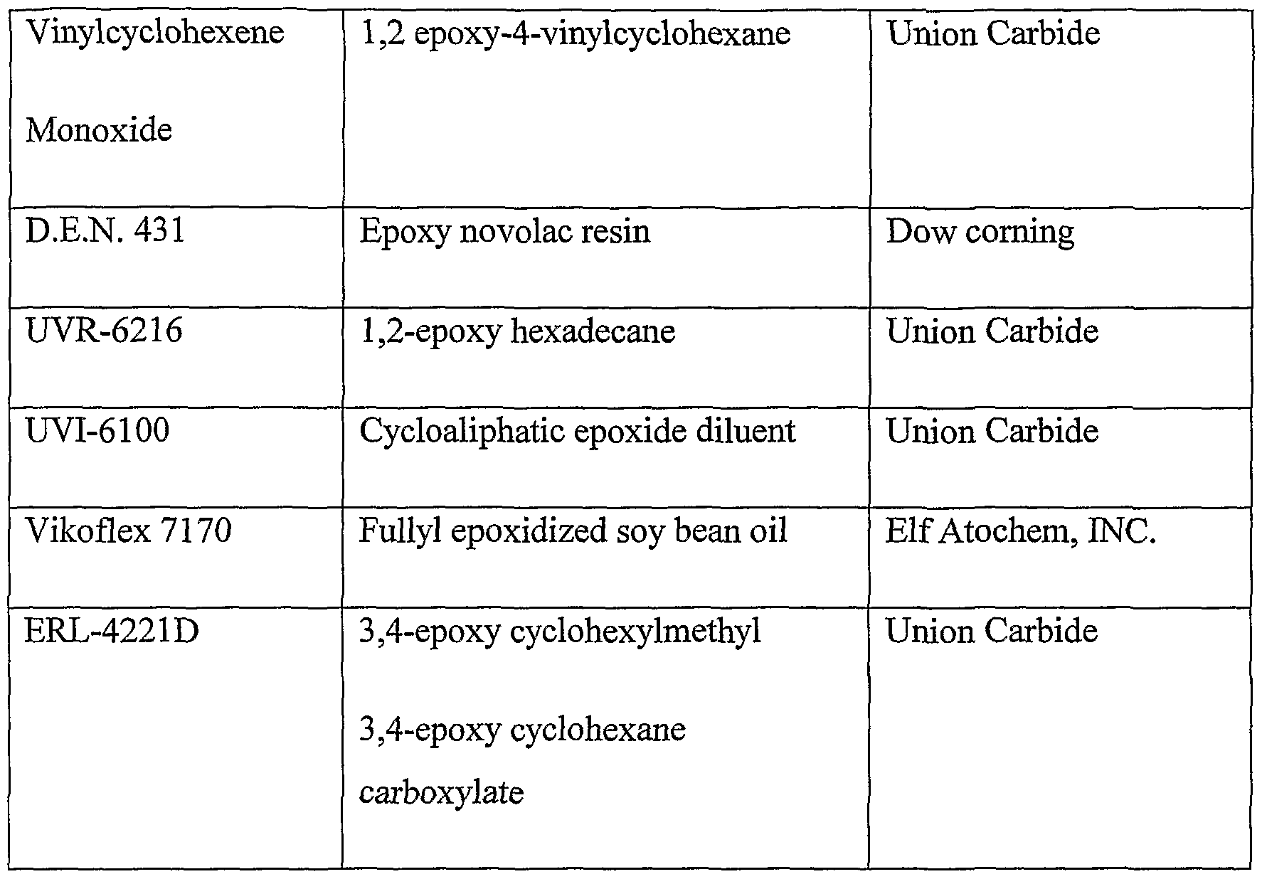
In one embodiment of the present invention, the first interface material may also include a curable component which is a molecule having one or more epoxy substituents. In one embodiment of the present invention, conventional epoxy monomers and oligomers which have at least one oxirane moiety may be used. Non-limiting examples of suitable epoxy containing molecules are displayed in Table 1 below (note other suppliers may be used for suitable materials): Table 1: Examples of epoxy-containing curable component
Figure imgf000035_0001
In one embodiment of the present invention, the first interface material may include any combination of an acrylic component as defined herein, a molecule having one or more epoxy substituents as defined herein, a molecule having one or more vinyl ether substituents as defined herein, vinylcaprolactam and vinylpyrolidone.
In one embodiment of the present invention, the curable component of the first interface material includes, inter alia, an acrylic monomer, an acrylic oligomer, an acrylic crosslinker and vinylcaprolactam. hi another embodiment, the curable component includes an acrylic component as defined herein and a molecule having one or more epoxy substituents as defined herein. In another embodiment, the curable component of the first interface material includes an acrylic component as defined herein and a molecule having one or more vinyl ether substituents as defined herein. In another embodiment, the curable component in the first interface material includes a molecule having one or more vinyl ether substituents as defined herein, and a molecule having one or more epoxy substituents as defined herein. The photo-initiator of the first interface material and of the second interface material may be the same or different, and is a free radical photo-initiator, a cationic photo-initiator, or any combination thereof.
The free radical photo-initiator may be any compound that produces a free radical on exposure to radiation such as ultraviolet or visible radiation and thereby initiates a polymerization reaction. Non-limiting examples of some suitable photo-initiators include benzophenones (aromatic ketones) such as benzophenone, methyl benzophenone, Michler's ketone and xanthones; acylphosphine oxide type photo-initiators such as 2,4,6-trimethylbenzolydiphenyl phosphine oxide (TMPO), 2,4,6-trimethylbenzoylethoxyphenyl phosphine oxide (TEPO), and bisacylphosphine oxides (BAPO's); benzoins and bezoin alkyl ethers such as benzoin, benzoin methyl ether and benzoin isopropyl ether and the like. Examples of photo-initiators are alpha-amino ketone, marketed by Ciba Specialties Chemicals Inc. (Ciba) under the trade name Irgacure 907, and bisacylphosphine oxide (BAPO's), marketed by Ciba under the trade name 1-819. The free-radical photo-initiator may be used alone or in combination with a co-initiator. Co-initiators are used with initiators that need a second molecule to produce a radical that is active in the UV-systems. Benzophenone is an example of a photoinitiator that requires a second molecule, such as an amine, to produce a curable radical. After absorbing radiation, benzophenone reacts with a ternary amine by hydrogen abstraction, to generate an alpha-amino radical which initiates polymerization of acrylates. Non-limiting example of a class of co-initiators are kanolamines such as triemylamine, methyldiethanolamine and tiiethanolamine.
Suitable cationic photo-initiators according to embodiments of the present invention may include compounds which form aprotic acids or Bronstead acids upon exposure to ultraviolet and/or visible light sufficient to initiate polymerization. The photo-initiator used may be a single compound, a mixture of two or more active compounds, or a combination of two or more different compounds, i.e. co-initiators. Non-limiting examples of suitable cationic photo-initiators are aryldiazonium salts, diaryliodonium salts, triarylsulphonium salts, triarylselenonium salts and the like. In one embodiment, a cationic photo-initiator for the present invention may be a mixture of triarylsolfonium hexafluoroantimonate salts marketed by Union Carbide as UVI-6974.
In one embodiment of the present invention, the composition suitable for building a three-dimensional object, may further include a curable compound, which is a sulfur-containing component. In one embodiment of the present invention, the sulfur-containing component is beta mercaptopropionate, mercaptoacetate, alkane thiols or any combination thereof. The addition of sulfur-containing components may significantly enhance the composition reactivity. At levels of about 5% of sulfur-containing component a significant reactivity enhancement is achieved. The mechanical properties of the composition may be determined depending on the sulfur-containing component used. The reactivity enhancement achieved by the use of sulfur-containing component, enables the incorporation in the polymerization reaction of non sulfur-conl ining components, which would not easily polymerize otherwise. Molecules having unsaturated double bonds, for example, low molecular weight polybuthadiene, is polymerized in the claimed compositions when it contains an appropriate sulfur-containing component. For example, a basic composition will contain 15% low molecular weight unsaturated molecule, 5% sulfur-containing component, 15% mono-functional monomer, 15% di-functional monomer and the rest other curable components according to the intended photopolymer properties. An example of a sulfur-containing component according to an embodiment of the present invention may be trimethylolpropane tri(3 -mercaptopropionate), manufactured by BRUNO BOCK Chemische Fabrik GMBH & CO. Other suitable substances may be used.
In one embodiment of the present invention, the composition suitable for building a three-dimensional object, further includes, inter alia, a low molecular weight polymer. An example of a low molecular weight polymer according to an embodiment of the present invention may be Styrene-Butadiene-Methacrylate block copolymers (KRATON D), manufactured by Dow Corning. Other suitable substances may be used.
In one embodiment of the present invention, the composition suitable for building a three-dimensional object, further includes, inter alia, a filler. The term filler is defined as an inert material added to a polymer, a polymer composition or other material to modify their properties and/or to adjust quality of the end products. The filler may be an inorganic particle, for example calcium carbonate, silica and clay. Of course other filler substances may be used. Fillers may be introduced in to polymer compositions in order to reduce shrinkage during polymerization or during cooling, for example to reduce the coefficient of thermal expansion, increase strength, increase thermal stability reduce cost and/ or adopt rheological properties. The use of standard fillers has also some drawbacks such as reduction of elasticity and an increase in viscosity. Additionally, large diameter fillers (>5 micron) are not appropriate for ink-jet applications.
Nano-particles fillers are especially useful in applications requiring low viscosity such as ink-jet applications. Compositions containing as much as 30%) nano-particle fillers are feasible, whereas the same concentration of more standard and higher diameter fillers (~>1 micron) produce at such concentration viscosities which are too high for ink-jet applications, hi one embodiment of the present invention, the nano-particle filler containing composition is clear. The composition is clear (e.g. transparent) since it contains no visual fillers. In contrast, compositions containing more standard and higher diameter visible fillers (~>1 micron), are not clear.
In one embodiment of the present invention, the composition optionally may contain pigments. In another embodiment, the pigment concentration may be lower than 35%. In another embodiment, the pigment concentration may be lower than 15%.
In one embodiment of the present invention, the filler may include particles such as particles having an average diameter of less than 100 nm. In another embodiment, the filler may include particles having a diameter in the range of 10-100 nm. In another embodiment, the filler may include particles having a diameter in the range of 20-80 nm. In another embodiment, the filler may include particles having a diameter in the range of 10-50 nm. In another embodiment, the filler may include particles having a diameter smaller than 10 nm. Examples of fillers that may be used in the composition are HIGHLINK OG (particle size spanning between 9 nm to 50 nm), manufactured by Clariant, and NANOCRYL (particle size below 50 nm), manufactured by Hanse Chemie. Other suitable substances may be used.
It was discovered that phase separation may be induced during the radiation curing process of the present method. In one embodiment of the present invention, the phase separation may produce a clear material, which may have improved impact-resistance. This composition, upon bending develops micro-cracks, before breaking. These micro-cracks can easily be distinguished due to the whitening of the stress area or stress line. In another embodiment, the phase separation results in a non-clear cured material. It was discovered that certain combinations of UV curable components induce phase separation during curing. Such compositions are clear before curing and may be clear, hazy or opaque after curing. Such compositions have an improved impact strength and higher elongation, when compared to similar compositions, which do not show such phase separation. For example, it was discovered that the addition of some silicon containing oligomers, at levels as low as 5%>, to the above described composition, may already create a substance which induces such phase separation. An example of a silicon acrylated molecule is Ebecryl 350, manufactured by UCB Chemicals. Of course other substances may be used.
One embodiment of the present invention provides a composition further includes a phase separation inducing component. In another embodiment, the phase separation inducing component is a silicon oligomer. In another embodiment, the concentration of the silicon oligomer is at least 5%.
In one embodiment of the present invention, phase separation may be induced during curing, resulting in a non-clear cured material. Certain combinations of UV curable composition suffer a phase separation process during curing. Such compositions are clear before curing and hazy to white after curing. Such compositions have an improved impact strength and higher elongation, when compared to similar compositions, which do not suffer from such phase separation. For example, the addition of some silicon containing oligomers, at levels as low as 5%, to the above described composition, may create a substance which suffers from such face separation. In one embodiment of the present invention, the first viscosity is about 80-500 cps. In another embodiment, the first viscosity is about 300 cps. Of course, compositions having other viscosities may be used.
In one embodiment of the present invention, the second viscosity is lower than 20 cps and wherein the second temperature is higher than 60°C. In another embodiment, the second viscosity is between 10 and 17 cps and wherein the second temperature is higher than 60°C. In another embodiment, the second viscosity is between 10 and 17 cps and wherein the second temperature is about 70-110°C. In another embodiment, the second viscosity is between 12 and 15 cps and wherein the second temperature is about 70-90°C. Of course, compositions having other viscosities may be used.
Other components of the first interface material and the second interface material according to embodiments of the present invention may be surface-active agents and inhibitors (typically, thermal stabilizers). A surface-active agent may be used to reduce the surface tension of the formulation to the value required for jetting or for printing process, which is typically around 30 dyne/cm. An example of a surface-active agent according to an embodiment of the present invention may be silicone surface additive, marketed by Byk Chemie under the trade name Byk 307. Inhibitors may be employed in the formulations of the first interface material and the second interface material to permit the use of the formulation at high temperature, for example around 85°C, without causing thermal polymerization.
In one embodiment of the present invention, the composition may further include, inter alia, at least one pigment and at least one dispersant. In one embodiment of the present invention, the pigment may be a white pigment. In another embodiment, the pigment may be an organic pigment. In another embodiment, the pigment may be an inorganic pigment. In another embodiment, the pigment may be a metal pigment or a combination thereof. In one embodiment of the present invention, the composition may further include, inter alia, a dye. An example of a white pigment according to an embodiment of the present invention may be organic treated titanium dioxide, marketed by Kemira Pigments under the trade name UV TITAN Ml 60 VEG. An example of an organic pigment according to an embodiment of the present invention may be an organic pigment marketed by Elementis Specialities under the trade name Tint Aid PC 9703. Examples of dispersants according to embodiments of the present invention may be dispersants including a copolymer with acidic groups marketed by Byk Chemie under the trade name Disperbyk 110, and a dispersant including a high molecular weight block copolymer with pigment affinic groups, marketed by Byk Chemie under the trade name Disperbyk 163. Furthermore, in one embodiment of the present invention, combinations of white pigments and dyes are used to prepare colored resins. In such combinations, the white pigment may have at least a double task: 1) to impart opacity; and 2) to shield the dye from UV radiation, to prevent bleaching of the resin. Thus, in accordance with one embodiment of the present invention, the first interface material further includes a dye. The dye may be chosen so as not to interfere with the curing efficiency of the formulation of the first interface material. The dye may be any of a broad class of solvent soluble dyes. Some non-limiting examples are azo dyes which are yellow, orange, brown and red; anthraquinone and triarylmethane dyes which are green and blue; and azine dye which is black. An example of a dye according to an embodiment of the present invention may be Solvent Red 127, marketed by Spectra Colors Corp. under the trade name Spectrasol RED BLG.
The relative proportions of the different components of the first interface material may vary. In one embodiment of the present invention, the first interface material includes the following components: 50% acrylic oligomer(s), 30% acrylic monomer(s), 15% acrylic crosslinker, 2% photoinitiator, surface active agent, pigments, and stabilizers. Of course, other compositions may be used.
Non-limiting examples of formulations of the first interface material are provided herein in Tables 2-4, to which reference is now made. Tables 2 and 3 illustrate examples of possible formulations of the first interface material. Table 4 illustrates examples of colored formulations, which include pigments, dispersants and dyes, as defined herein. To any of the examples in Tables 2 and 3 may be added the combination of the colorants of Table 4. The individual substances, suppliers, combinations, etc., are given by way of example only. Table 2: Examples of Characteristic Formulation Components of First Interface Material
Figure imgf000042_0001
Figure imgf000043_0001
Figure imgf000044_0001
Table 4: Examples of colored formulations of first interface material
Figure imgf000045_0001
In one embodiment of the present invention, the formulation of the first interface material is presented in entry No. 14 of Table No. 3. According one embodiment of the present invention, the first interface material includes: an acrylic oligomer, which may be any acrylic oligomer as defined herein, and which may be an urethane acrylate oligomer; an acrylic monomer, which may be any acrylic monomer as defined herein, and which may be phenoxy ethyl acrylate; an acrylic crosslinker, which may be any acrylic crosslinker as defined herein, and which may be trimethylol propane triacrylate; a radical photo-initiator, which may be any radical photo-initiator as defined herein, and which may be alpha-amino ketone; a surface agent, which may be a silicone surface additive; an inhibitor, which may be 4-methoxyphenol; and vinylcaprolactam.
SECOND INTERFACE MATERIAL
The second interface material (in one embodiment, the support material) is a composition typically formulated to support the building of a three-dimensional object. In one embodiment of the present invention, the second interface material is formulated to form a release layer to permit a manual easy separation or cleaning of the three-dimensional object from its support.
In one embodiment of the present invention, the second interface material may be one of two different principle kinds: 1) a liquid material lacking any curable groups that remains liquid even after irradiation. In one embodiment, the liquid is water miscible and is easily washed out by water, or with other material. In another embodiment the liquid is non water-miscible and is easily washed out by water or by a water detergent solution and 2) a solid or semi-solid material that is formulated as a weak curable material. The solid or semi-solid material, when cured, may be capable of swelling in water or in alkaline or acidic water or water detergent solution. Thus, when cured, the second interface material may swell and almost break upon exposure to water, or in alkaline or acidic water or water detergent solution, with minimum manual work required. In both cases the second interface material is formulated so as to permit fast, easy and efficient removal of the second interface material and cleaning of the three-dimensional model from its support. In one embodiment, the second interface material of the present invention may include, inter alia, at least one non-reactive and low toxicity compound, at least one surface-active agent and at least one stabilizer.
One embodiment of the present invention provides a composition suitable for support in building a three-dimensional object, the composition may include, inter alia, a non-curable component, a curable component, wherein the non-curable component is not reactive with the curable component, a surface-active agent, and a stabilizer, wherein the composition has a first viscosity of about 20-500 cps at a first temperature, wherein the first temperature is ambient temperature, and a second viscosity lower than 20 cps at a second temperature wherein the second temperature is higher than the first temperature, wherein, after irradiation, the composition results in a semi solid material. Of course, compositions having other viscosities may be used.
In one embodiment of the present invention, the composition suitable for support in building a three-dimensional object, after irradiation, may result in a semi-solid material. In another embodiment, the semi-solid material may be gel type material. In another embodiment, the composition may result in a liquid material. In another embodiment, the composition results in a solid material that is formulated as a weak curable material. In another embodiment, upon irradiation, the composition results in a material that is capable of swelling in water or in alkaline or acidic water. Thus, when irradiated, the second interface material swells and almost breaks upon exposure to water, with minimum manual work required.
In one embodiment of the present invention, the second interface material is formulated so as to permit fast, easy and efficient removal of the second interface material and cleaning of the three-dimensional model from its support. In one embodiment of the second invention, the curable component is a reactive component. In another embodiment of the present invention, the reactive component can undergo polymerization. According to one embodiment, the second interface material is formulated as a curable composition that is capable of solidifying upon curing. In one embodiment of the second invention, the curable components may be similar to those used in the first interface material, but chosen specifically to give a hydrophiUic cured resin, with weak mechanical properties. Thus, upon curing, a solid composition is formed that is weak and can be easily pulverized for example by hand or using water.
In one embodiment of the present invention, the curable component may be a (meth)acrylic component. In another embodiment, the (meth)acrylic component may be a (meth)acrylic monomer. In another embodiment, the (meth)acrylic component may be a (meth)acrylic oligomer. In another embodiment, the (meth)acrylic component may be a (meth)acrylic crsosslinker. In another embodiment, the (meth)acrylic component may be any combination of a (meth)acrylic monomer, a (meth)acrylic oligomer and a (meth)acrylic crsosslinker. In one embodiment of the present invention, the composition may further include, inter alia, at least one photo-initiator. In one embodiment of the present invention, the photo-initiator may a free radical photo-initiator, a cationic photo-initiator, or any combination thereof. The photo-initiator may be any photo-initiator, as defined above. One embodiment of the present invention provides a composition suitable for support in building a three-dimensional object, the composition may include, inter alia, a non-curable component, a curable (meth)acrylic component, wherein the non-curable component is not reactive with the curable component, a surface-active agent, a free radical photo-initiator and a stabilizer, wherein the composition has a first viscosity of about 20-500 cps at a first temperature, wherein the first temperature is ambient temperature, and a second viscosity lower than 20 cps at a second temperature wherein the second temperature is higher than the first temperature, wherein, after irradiation, the composition results in a solid, a semi-solid or a liquid material.
In one embodiment of the present invention, the composition may further include, inter alia, water. In one embodiment of the present invention, the composition further includes a water miscible component that is, after irradiation or curing, capable of dissolving or swelling upon exposure to water, to an alkaline or acidic water solution or to water detergent solution. In another embodiment, the water miscible component is a (meth)acrylated urethane oligomer derivative of polyethylene glycol, a partially (meth)acrylated polyol oligomer, a (meth)acrylated oligomer having hydrophiUic substituents, polyethylene glycol mono or di (meth)acrylated, acrylamide, Acryloylmorpholine(ACMO) or any combination thereof. In another embodiment, the hydrophilic substituents are acidic substituents, amino substituents, hydroxy substituents, ionic substituents or any combination thereof. Non-limiting examples of acrylic components for use in the second interface material according to embodiments of the present invention may be polyethylene glycol monoacrylate, marketed by Laporte under the trade name Bisomer PEA6, polyethylene glycol diacrylate, marketed by Sartomer under the trade name SR-610, methoxypolyethyleneglycole 550 monomethacrylate, and the like. In one embodiment of the present invention, the curable component of the second interface material may be a water miscible component that is, after curing, capable of swelling upon exposure to water or to an alkaline or acidic water solution. Non-limiting examples of water miscible components according to embodiments of the present invention are an acrylated urethane oligomer derivative of polyethylene glycol - polyethylene glycol urethane diacrylate, a partially acrylated polyol oligomer, an acrylated oligomer having hydrophiUic substituents, or any combination thereof. The hydrophilic substituents are acidic substituents, amino substituents, hydroxy substituents, or any combination thereof. An example of an acrylated monomer with hydrophiUic substituents is betha-carboxyethyl acrylate, which contains acidic substituents.
In one embodiment of the present invention, the curable component of the second interface material may also be a molecule having one or more vinyl ether substituents, which may be any of the compounds as defined herein. In one embodiment of the present invention, the concentration of component that includes a molecule having one or more vinyl ether substituents is in the range of 10-30%. In another embodiment, the concentration is 15-20%. In another embodiment, the concentration is 15%). Other concentrations may also be used. An example of vinyl ether for the second interface material is 1,4-cyclohexane dimethanol divinyl ether, marketed by ISP under the trade name CHVE. Other molecules having one or more vinyl ether substituents may be used.
In one embodiment of the present invention, the curable component of the second interface material is an acrylic oligomer. In another embodiment, the curable component of the second interface material is a combination of an acrylic component as defined herein and a water miscible component as defined herein. In another embodiment, the curable component of the present invention is a combination of an acrylic component as defined herein and a molecule having one or more vinyl ether substituents, as defined herein. In another embodiment, the curable component of the present invention is a combination of a water miscible component as defined herein, and a molecule having one or more vinyl ether substituents, as defined herein. Other combinations may also be used. In one embodiment of the present invention, the composition further includes, inter alia, a sulfur-containing component. In another embodiment, the sulfur containing component is beta mercaptopropionate, mercaptoacetate, alkane thiols or any combination thereof. The sulfur-containing component may be any sulfur-containing component, as defined above.
In one embodiment of the present invention, the non-curable component of the second interface material is a non-curable component. In another embodiment the non-curable component is non-polymerizing component. In another embodiment, the non-curable component is a low toxicity compound. In another embodiment, the non-curable component is a water miscible one. In another embodiment, the non-curable component is a non-water miscible one. In one embodiment of the present invention, the non-curable component is chosen to enhance the water-swelling rate, and to reduce the mechanical strength of the second interface material. High water diffusion rate is desirable in order to minimize the time needed for the water cleaning process of the three-dimensional model. Non-limiting examples of non-curable components according to embodiments of the present invention may be polyethylene glycol marketed by Aldrich under the trade name PEG 400, methoxypolyethylene glycol marketed by Aldrich under the trade name methoxycarbowax 500 and 1000, propylene glycol and paraffin oil. Other examples are ethoxylated polyols and glycerol. In one embodiment of the present invention, the second interface material is formulated as a liquid. The liquid formulation is a non-curable composition that remains liquid even after radiation exposure. Thus, the liquid formulation includes non-reactive components and does not include reactive components that are capable upon solidifying upon curing. In one embodiment of the present invention, the material may be water miscible, and may easily be washed out with water.
In one embodiment of the present invention, the non-curable component is polyethylene glycol, methoxypolyethylene glycol, glycerol, ethoxylated polyol, propylene glycol or any combination thereof. In another embodiment, the non-curable component is a non-water miscible compound. In another embodiment, the non-water miscible compound is paraffin oil. Other non-curable substances may be used. One embodiment of the present invention further provides a composition suitable for support in building a three-dimensional object, the composition may include, inter alia, at least one non-curable component, at least one curable component including, inter alia, a molecule having one or more epoxy substituents, wherein the non-curable component is not reactive with the curable component, at least one surface-active agent, at least one cationic photo-initiator and at least one stabilizer, wherein the composition has a first viscosity of about 20-500 cps at a first temperature, wherein the first temperature is ambient temperature, and a second viscosity lower than 20 cps at a second temperature wherein the second temperature is higher than the first temperature, wherein, after irradiation, the composition results in a semi solid material.
In one embodiment of the present invention, the first temperature is a room temperature. In another embodiment, the room temperature is between 20-30°C. In another embodiment, the first temperature is ambient temperature. In another embodiment, ambient temperature is between 10-40°C. In another embodiment, ambient temperature is between 15-35°C. In another embodiment, ambient temperature is between 20-30°C.
In one embodiment of the present invention, the second temperature is higher than 40°C. In another embodiment, the second temperature is higher than 50°C. In another embodiment, the second temperature is higher than 60°C. i another embodiment, the second temperature is higher than 70°C. Besides swelling, another characteristic of the support upon exposure to water or to an alkaline or acidic water or water detergent solution may be the ability to break down during exposure to water or to an alkaline or acidic water solution. In one embodiment of the present invention, because the second interface material is made of hydrophiUic components, during the swelling process, internal forces appear and cause fractures and breakdown of the cured second interface material.
In addition, the second interface material may be at least partially water-soluble. At least part of the second interface material is may be completely water soluble/miscible. During the removal of the support and/or release layers, the water soluble/miscible components are extracted out with water. In addition, in one embodiment of the present invention, the second interface material liberates bubbles upon exposure to water or to an alkaline water or acidic water solution. The bubbles are intended to help in the process of removal of the support and/or release layers from the construction layers. In one embodiment of the present invention, the bubbles may be liberated by a bubble releasing substance (BRS) that is present in the water solution that is used to clean out the three-dimensional object. Such a substance may be a carbonate or bicarbonate, for example sodium bicarbonate (SBC). During the swelling process, at least part of the SBC is introduced or absorbed into the second interface material, where it is transformed into carbon dioxide gas (CO ) and a water-soluble salt. The trigger for the production of CO2 may be the reaction of the SBC with an acid functionality present in the second interface material. Such acid functionality may be introduced as part of the second interface material formulation or introduced later, after curing, using an acid water solution. For example, the first step may be to put the three-dimensional object with its support in a water solution containing a SBC, then to place the same object in an acidic solution. The acid will start to decompose the SBC and produces gas (bubbles).
In another embodiment, the substance that liberates gas is already present in the formulation of the second interface material. For example, the second interface material may contain calcium carbonate as a solid filler. In that case, the trigger is the introduction of the second interface material in a water or acidic solution.
It should be clear that a BRS is not limited to a sodium bicarbonate or calcium carbonate and an acidic water solution. Other chemical reagents and reactions may be used to achieve the same result - the production of bubbles inside the matrix of the second interface material. For example, the SBC may be any alkaline metal or alkaline earth metal carbonate or bicarbonate.
In one embodiment of the present invention, the non-curable component is a non-water miscible compound. In another embodiment, the non-water miscible compound is paraffin oil. In one embodiment of the present invention, the composition further includes, inter alia, a fiUer. In another embodiment, the filler includes particles having a diameter of less than 1 micron.
In one embodiment of the present invention, the composition further includes a low molecular weight polymer.
In one embodiment of the present invention, the first viscosity composition suitable for support in building a three-dimensional object is about 30-200 cps.
In one embodiment of the present invention, the second viscosity of the composition suitable for support in building a three-dimensional object is lower than 20 cps. In another embodiment, the second viscosity is between 10 and 17 cps. In another embodiment, the second viscosity is between 12 and 16 cps.
Having these viscosities, the first and second interface material may be distinguished from certain prior art formulations designed for ink-jet printing, which may have low viscosity at room temperature, the temperature at which the printing is typically conducted. High viscosity at room temperature may be a desirable property for three-dimensional objects, a feature that may be lacking in the prior art formulations.
In one embodiment of the present invention, the composition further includes, inter alia, a component able to produce gas upon exposure to water or to an alkaline or acidic water solution. In another embodiment, the component is sodium bicarbonate, calcium bicarbonate or a combination thereof. Other suitable substances may be used.
In one embodiment of the present invention, the second interface composition further includes, inter alia, a pigment, a dye or a combination thereof. In another embodiment, the pigment is a white pigment, an organic pigment, an inorganic pigment, a metal pigment or a combination thereof. Examples of formulations of the second interface material are provided herein in
Table 5 and Table 6, to which reference is now made. Tables 5 and 6 display various formulations that are suitable for use as the second interface material. The individual substances, suppliers, combinations, etc., are given by way of example only. Table 5: Examples of Characteristic Formulation Components of Second Interface Material
Figure imgf000054_0001
Figure imgf000055_0001
Table 6: Examples of Possible Formulation Compositions of Second Interface Material
Figure imgf000056_0001
A formulation of the second interface material is presented in entry No. 3 of Table 6. According to this embodiment of the present invention, the second interface material includes: a water swelling oligomer, which may be any water swelling oligomer as defined herein, and which may be polyethylene glycol; a non-curable component, which may be any non-curable component as defined herein, and which may be polyethylene glycole; a radical photo-initiator, which may be any radical photo-initiator as defined herein, and which may be alpha-amino ketone; a surface agent, which may be a silicone surface additive; and an inhibitor, which may be 4-methoxyphenol.
Another formulation of the second interface material is presented in entry No. 4 of Table 6. According to this embodiment of the present invention, the second interface material includes: a water swelling oligomer, which may be any water swelling oligomer as defined herein, and which may be polyethylene glycole monoacrylate; a non-curable component, which may be any non-curable component as defined herein, and which may be polyethylene glycole; a radical photo-initiator, which may be any radical photo-initiator as defined herein, and which may be benzophenone; a co-initiator, which may be any co-initiator as defined herein, and which may be triethanolamine; a surface agent, which may be a silicone surface additive; and an inhibitor, which may be 4-methoxyphenol. The first interface material and the second interface material are suitable for use in, for example, the method for three-dimensional printing which is described in U.S. Patent Application 09/412,618, assigned to the Assignees of the present application and is incorporated herein by reference. Other methods may be used. Briefly, the method according to one embodiment includes: dispensing a first interface material from a printing head; dispensing a second interface material from the printing head; and combining the first interface material and the second interface material in pre-determined proportions to a produce a multiplicity of construction layers for forming the three-dimensional model.
The method (Fig. 3) according to an embodiment of the present invention includes dispensing a first composition suitable for building a three-dimensional object from a dispenser (102), dispensing a second composition suitable for support in building a three-dimensional object from a dispenser (104), combining the first composition and the second composition in pre-determined proportions to produce a multiplicity of construction layers for forming the three-dimensional object (106), curing the first composition resulting in a solid form (108), and irradiating or curing second composition resulting in a liquid, a solid or a semi-solid form (110). Of course, the method may include other steps or series of steps.
One embodiment of the present invention further provides a method for the preparation of a three-dimensional object by three-dimensional printing, the method may include the steps of dispensing a first composition suitable for building a three-dimensional object from a dispenser, the first composition may include, inter alia, a curable component, having a functional group, wherein if the functional group is a polymerizable reactive functional group, then the functional group is a (meth)acryιic functional group, a photo-initiator, a surface-active agent; and a stabilizer, dispensing a second composition suitable for support in building a three-dimensional object from a dispenser, the second composition may include a non-curable component, a curable component, wherein the non-curable component is not reactive with the curable component, a surface-active agent and a stabilizer, combining the first composition and the second composition in pre-determined proportions to produce a multiplicity of construction layers for forming the three-dimensional object, whereby the first composition is cured resulting in a solid form, and whereby the second composition is irradiated or cured resulting in a liquid, a solid or a semi-solid form.
In one embodiment of the present invention, the method may further include the step of generating data for a pre-determined combination of the first composition and the second composition to produce a multiplicity of support layers for supporting the three-dimensional object.
In one embodiment of the present invention, the method may further include the step of generating data for a pre-determined combination of the first composition and the second composition to produce a multiplicity of release layers for releasing the three-dimensional object from the support layers.
In one embodiment of the present invention, the first composition and the second composition are dispensed simultaneously. In another embodiment, the first composition and the second composition are dispensed sequentially. In another embodiment, the first composition is dispensed first. In another embodiment, the second composition is dispensed first. In another embodiment, more than one first composition is used. In another embodiment, the more than one second composition is used.
In accordance with one embodiment of the present invention, the method further includes the step of curing the first interface material. Further, when the second interface material includes a curable component, the method may further include the step of curing the second interface material. Curing may be carried out for example, as described in U.S. Patent Application 09/412,618. For example, the curing method is by radiation, such as Ultraviolet (UV) and/or Visible (Vis) and/or Infra Red (TR) and/or UV-Vis radiation and/or Electron Beam (EB). In one embodiment of the present invention, the curing method is UV-Vis radiation. Other suitable curing methods may be used. In operation, in order to obtain layers of different modulus of elasticity and a different strength, the first interface material and the second interface material are combined in pre-determined proportions. For example, in order to obtain layers having a higher modulus of elasticity and a higher strength such as the construction layers, a suitable combination that contains mostly the first interface material may be used. Further, in order to obtain layers having a lower modulus of elasticity and a lower strength such as the release layers, a suitable combination that includes mostly the second interface material may be used.
By way of example, in order to produce the construction layers and/or the support layers, a combination that includes 90-100% of the first interface material and 0-10% of the second interface material may be used. Further, in order to produce the release layers, a combination that includes 0-10% of the first interface material and 90-100% of the second interface material may be used. In another embodiment, in order to produce support layers that have a lower modulus of elasticity and a lower strength than the construction layers, a combination that includes 30-70%) of the first interface material and 70-30% of the second interface material may be used.
Thus a three-dimensional object is produced which is included of a core consisting of a multiplicity of construction layers. The construction layers are formed by combining predetermined proportions of the first interface material and the second interface material.
One embodiment of the present invention further provides a three-dimensional object comprised of a multiplicity of construction layers, wherein the construction layers are prepared by combining pre-determined proportions of a first composition and a second composition according to the invention. In another embodiment the three-dimensional object is comprised of a core, consisting of a multiplicity of construction layers, wherein the construction layers are prepared by combining pre-determined proportions of a first composition and a second composition according to the invention.
One embodiment of the present invention provides a three-dimensional object including the composition according the invention. In one embodiment of the present invention, the three-dimensional object further includes a multiplicity of support layers for supporting the core. The support layers are prepared by combining pre-determined proportions of the first interface material and the second interface material. The support layers may be designed exactly like to construction layers, or may be designed to be weaker (lower modulus of elasticity) than the construction layers.
In one embodiment of the present invention, the three-dimensional object may further include a multiplicity of support layers for supporting the core, wherein the support layers are prepared by combining pre-determined proportions of the first composition and the second composition. In another embodiment, the support layers support the construction layers. In another embodiment, the support layers have the same strength as the construction layers. In another embodiment, the support layers have the same modulus of elasticity as the construction layers, h another embodiment, the support layers have a lower modulus of elasticity and/or a lower strength than the construction layers. In one embodiment of the present invention, the three-dimensional object further includes a multiplicity of release layers for releasing the support layers from the construction layers. In one embodiment of the present invention, the release layers are positioned between the support layers and the construction layers. The release layers are prepared by combining pre-determined proportions of the first interface material and the second interface material.
In one embodiment of the present invention, the three-dimensional object may further include a multiplicity of release layers for releasing the support layers from the core, wherein the release layers are positioned between the support layers and the construction layers; wherein the release layers are prepared by combining pre-determined proportions of the first composition and the second composition. In another embodiment, the release layers have a lower modulus of elasticity and/or a lower strength than the construction layers and the support layers.
Deformation of printed objects may occur during or following 3-D object printing.
One example of deformation that may occur during the printing process is an inward contraction of the object being printed, due, for example, to accumulative strain on the body of the object during the course of printing. For example, each layer of an object may be deposited during the X movement(s) of the printing head. A layer may generally be continuous, e.g., material may be jetted selectively but continuously from the printing head nozzles during the course of printing in the X direction, to form a continuous layer of material. Typically, a layer is deposited generally in one plane, but in alternate embodiments this need not be the case. In the case of an object being built on a layer upon layer basis, for example, a layer may contract as a result of curing and cause to strain to accumulate within the body of the printed object. The contraction of subsequent layers deposited may add to the strain on the body of the printed object and may result, for example, in the deformation of the object. The accumulative strain may occur, for example, in a radial direction towards the center of the object. In such a case, the external parts of the printed object may be pulled towards the object's center, thus producing object curl (e.g., lifting of the object base edges upwards). Other types of deformations or defections may also occur. Reference is now made to Fig. 4A and 4B, which are schematic illustrations of object constructions according to some embodiments of the present invention. In Fig. 4A, using what may be referred to as "segmentation", at least part of each layer 205 may be built in non-continuous segments. Such segments may in alternate embodiments be contiguous - for example small portions of segments may touch. Each of the segments 210 that may constitute a layer 205 or part of a layer may be separated by gaps or spaces 215 (such gaps or spaces need not completely separate segments). Segments 210 are typically, deposited generally in one plane, but in alternate embodiments this need not be the case. In the case that segments shrink on curing, segments 210 may shrink separately upon curing, thereby inducing a reduced stress gradient or zero stress gradient towards the center of layer 205. In this way, the accumulative stress that may produce object deformation and/or 'curl' may be eliminated or reduced. According to another embodiment of the present invention, non-continuous layers may be deposited in selected areas that are to be segmented, while continuous layers, for example, may be deposited in areas that may not require segmentation. In other embodiments, non-contiguous or substantially non-contiguous segments may be deposited in systems where no shrinkage occurs. Two possible examples of segmentation constructions may be seen with reference to Fig. 4B, which is a view from above a printing tray. Other segmentation patterns and methods may be used. Type "A" may include, for example, segments of object construction 210 surrounded in the X and Y directions by spaces, gaps or areas of non-object construction 215.. Type "B" may comprise, for example, segments of object constructions 210 that are joined in the Y-direction but separated by spaces or gaps 215 in the X-direction. Other formations or combinations of formations may be used.
Reference is now made to Fig. 4C, which is a flowchart illustrating a method for printing of 3-D objects, according to some embodiments of the present invention. As can be seen with reference to Fig. 4C, the method may include, for example, depositing non-continuous layers of interface material. For example, at block 20, a segment or portion of a layer of interface material may be deposited. At block 21 a gap or space may be allocated as a space, and may be left free of deposited material after the previous portion of material was deposited. At block 22 an additional portion of the layer of interface material may be deposited, for example, after the space of the previous deposit of material, thereby forming a non-continuous layer. The portions may be cured after being deposited.
In some embodiments, as can be seen with reference to Fig. 4D, at block 25, when laying and curing of such segmented layers, space may be allocated and left free of deposited material between the segments. At block 26, these spaces, which may be between segments or partially between segments, may be filled and/or otherwise compensated for, in order to create, for example, a continuous layer out of the previously segmented layer. Various suitable methods may be used to fill in spaces between segments. For example, such spaces may be filled in, either simultaneously or subsequently, using substantially the same interface material that may be applied in a subsequent movement of printing head 12. In another example, the spaces may be filled in using substantially the same material, by applying at least one additional layer slightly offset or displaced from the previous layer, so as to be, for example, deposited in between the lines or spaces of the segments laid in previous layers. A further example may be to fill in the spaces using a substantially different type of material, applied in the same and/or subsequent movement of printing head 12. Subsequent layers may be slightly displaced or shifted, for example, in the X and/or Y-directions. Various types and combinations of types of segments, spaces, and fillings may be used. Any combination of the above steps may be implemented. Further, other steps or series of steps may be used.
For example, the material(s) may be jetted non-continuously, for example, in a start/stop/start/stop jetting process, as the printing head moves in the X direction. The printing nozzles may jet material(s) over areas predetermined to be object segments and may cease jetting material over adjacent areas that are predetermined to be spaces In the areas where material has been jetted by the nozzles, a segment may be created. In the areas where material has not been jetted by the nozzles, a space between segments may be created. The layers may be cured subsequent to deposition. However, as the curer, e.g., a source of radiation, may follow the path of the printing head, curing may occur in a sweeping motion, curing material just deposited, in the wake of the printing head. That is, the process may be continuous. Other curing methods may be used.
The segmentation method described herein may use various suitable materials to construct the non-continuous layers, segments, spaces, and/or fillings. For example, segmentation may use any of the materials or combinations of materials described herein, for example any first interface material according to the invention, any second interface material according to the invention, any composition suitable for building a three-dimensional object according to the invention, any composition suitable for supporting a three-dimensional object according to the invention, any combination thereof, or any other appropriate material.
According to some embodiments of the present invention, apparatuses, methods, and compositions may be provided to build release layers or constructions to enable easy removal of support constructions following printing of 3-dimensional objects. Release layers may be, for example, relatively soft constructions that may be constructed in relatively thin layers between the 3-D object being built and the support constructions layers supporting the object, to help provide relatively clean and easy removal of the support construction from the 3-D object or removal of certain portions of interface material or objects (cured or otherwise) from other portions or objects, after completion of the printing process. For example, the 'width' of release layers may vary between a few microns (e.g., similar to a construction layer in some embodiments) and a few hundreds of microns (e.g., similar to the width of a few construction layers in some embodiments).
Reference is now made to Fig. 5A, which is a flowchart illustrating a method for printing a support construction for 3-D objects, according to some embodiments of the present invention. As can be seen with reference to Fig. 5A, the method may include, for example, at block 31, dispensing interface materials in predetermined amounts and combinations, from at least one dispensing unit 16 of printing apparatus 15, to form a support construction. Layers of the support construction may include a first interface material (e.g., modeling material), a second interface material (e.g., support material) and/or other materials or combinations of materials. For example, the support construction may be constructed from support material alone, or may include modeling material, possibly providing additional strength and/or elasticity to the support construction.
At block 32, according to some embodiments, the support construction may be surrounded or partially surrounded by a rigid construction, for example, it may be contained within or partially within a rigid shell. The rigid construction may be built, for example, from modeling material, or other suitable material that may be, for example, substantially similar in strength and elasticity to the object. The rigid construction may be built to contain the support construction which itself may contain, for example, elements of modeling material surrounded by support material. In this way a rigid support construction may be formed, which may, for example, provide strong support for a 3-D object.
At block 33, a release construction layer may be constructed around the rigid construction of the support construction, to enable easy separation of the rigid construction from the object which is supported by the rigid construction. The shape of the support construction may be determined according to the shape of the object it supports and therefore the shape of the rigid construction may be the shape of the outer surface of the support construction.
At block 34 the support construction may be separated from the object, for example by slight mechanical force, due to the relatively soft release layer between the rigid object and the rigid support construction. For example, separation may occur due to manual manipulation, using a water, air or other fluid stream, etc.
For example, if the support geometry required is intricate, due, for example, to intricate object geometry, support constructions may be divided into a number of smaller support constructions in order to facilitate their dismantling. Each support construction may be contained within its own rigid support construction.
In a further embodiment, a support construction, which may be, for example, of a gel-like consistency after curing (other consistencies, such as relatively solid, may be used), may be filled with different combinations of support material and modeling material, for example, producing a soft bulk material. In this way, for example, the soft and possibly weak support construction may be strengthened by combining into the support construction a framework or construction comprised of, for example, modeling material, which is harder. In this way the whole 'support construction' , which may include support and modeling materials etc., may be relatively firm and yet still soft. This may be referred to as a 'soft bulk material', e.g., which may be a soft material with 'bulk' content. In one embodiment of the present invention the modeling material may be laid as a 'grid' or 'skeleton' within the support material, to provide added strength to the support construction.
In some embodiments, in order to facilitate dismantling of such support constructions from a printed object, a support construction may be designed to be dismantled as a single unit or in a number of units after printing is completed. In one embodiment, a minimal 'space' may be defined or allocated and left free of deposited materials between the 3-D object to be printed and the object's support construction. This space may include, for example, one or more release construction layers, which may consist, for example, predominantly of support material (optionally with a relatively small element of modeling material), hi one embodiment, release constructions may not solidify or may solidify partially to provide a relatively soft layer or layers of material that may enable easy release from a printed object. In one embodiment of the present invention, the release construction layers may not solidify upon irradiation and may remain in, for example, a viscous liquid state, i.e., may remain in a non-polymerized state. In another embodiment of the present invention, the release construction layers may solidify or at least partially solidify upon irradiation, for example, having soft or semisolid gel-like consistency. Such 'soft' release construction layers may help to remove the support construction after completion of the printing process. Removal of such support construction, which may include relatively hard layers, may be relatively easy to perform, and may be performed using little or minimal force.
Reference is now made to Fig. 5B, which is a schematic illustration of a 3-D object support construction 300 with a rigid exterior construction 305, according to some embodiments of the present invention. As can be seen with reference to Fig. 5A, support material 320 may be surrounded or partially surrounded by a rigid exterior 305. The rigid exterior 305 may be constructed from material that may become rigid upon curing and/or cooling, to form, for example, a shell like exterior. Support material 320 together with rigid exterior 305 may form the 3-D object support construction 300. Support construction 302 may be surrounded or partially surrounded by a relatively soft layer 320, for example, a release layer by, to enable support construction 300 to be easily separated from object 315.
In some embodiments, for example, release construction may be non-planar. For example, release construction material may not necessarily be deposited as a 'layer', and may be deposited in selected locations in the X-Y directions, for example, on top of a previous layer of interface material (e.g., Z direction). The release construction material that may be deposited between the 3-D object (e.g., the modeling construction) and the adjacent support constructions), may fill the space between the constructions, for example, during each movement of the printing head along the X-Y axes. An example of a conical shaped object (other shapes of objects may be constructed) surrounded by support construction, printed with release construction material as described herein, may be seen with reference to Fig. 5C, which shows a side view of an object 35. The 'release layer' 30 is depicted as a thin line separating the object construction 35 and the support structure 40. Fig. 5D illustrates a view of a 'slice' of the constructed object. Release construction 30 is indicated by a thin line encircling the conical object 35, and separating the object from the surrounding support construction 40. Other release layer dimensions and compositions may be used. Release layers may be used between other sections of interface material, not necessarily designated "object" and "support".
In one embodiment, instructions or indications for, for example, handling, construction, or deconstruction of a finished object may be deposited, constructed or printed directly on the interface material forming, for example, the object, support constructions, release constructions, etc. For example, indicators indicating a preferable removal direction or order, or instructions for removal or deconstruction of support constructions, may be printed or otherwise deposited on support constructions.
System controller 15 may have software or executable code that is programmed with predefined instructions for construction of a 3-D object based on the 3-D data received from a 3-D data source, for example, CAD system 22. Controller may provide, for example, a building plan for an object to be built, which may include, for example, the necessary object construction(s), support construction(s), and/or the release construction(s) between the object and support construction(s). In one embodiment of the present invention controller may enable provision of a set of direction indicators, for example, arrows (e.g., Dl, D2, ... Dn) which may define, for example, the position and direction of placement of the release construction layers, and the 'line' along which the support constructions may be removed after printing. Such indicators may be provided in the controller software, and may appear, for example, as a diagram which may be viewed on a display apparatus 22, for example, a computer screen or other suitable output device. For example, the various direction indicators may be displayed in different colors, or with different symbols. Raised or depressed printing may be used. For example, the set of Dl, D2... Dn indicators may enable the printing apparatus to construct the object and support constructions etc. in such a way so as to enable a recommended procedure of extraction of elements of the support construction after printing. In addition, an order of priority of the arrows or other indicators may be set, e.g., the order of priority of the release directions of the structure, which may be determined by the software. Where a number of support structures are required, an optimal order of their removal may be determined by the software or by an operator. In some embodiments structure removal indicators may be visual, for example, they may be constructed from letters, symbols colors, patterns, or other suitable markings. Indicators may be defined in the X, Y and/or Z-directions. For example, as can be seen with reference to Fig. 5E, one support construction 300 may be beneath an obj ect 315, and one support construction 310 may be penetrating object 315 from the side. Construction 300 may be marked with a direction 325, for example, Dl, meaning that it should be removed first, for example, using an arrow showing the direction of preferred removal for this support construction, (e.g., downwards). Construction 310 may be marked with a direction 330, for example, D2, meaning that it should be removed second, with, for example, an arrow at about a 45-degree angle downwards, indicating the direction of its preferred removal. The angle of removal of D2 indicates the line along which the support may efficiently be removed, and may dictate the angle of the 'break' between two adjacent supports, to help facilitate removal of each support structure. Between object 315 and support constructions 300 and 310, and between the support constructions 300 and 315 support material 320 (e.g., soft material) may be dispensed, for example, a release construction layer. Other suitable marking systems may be used, and the objects shown are for example only - other objects may be built, having other support or other auxiliary constructions.
As can be seen with reference to Fig. 5F, at block 36 an order or priority of the indicators may be defined, for example, according to the preferred order of removal of the support construction(s). In one embodiment of the present invention, the controller software may, for example, calculate and define the direction indicators and/or order of removal of the support construction(s). In the above embodiments and other suitable embodiments, the software may define, for example, the release construction layers in such a way that each construction may be removed substantially without interfering with or otherwise disturbing the removal of other support structures, due, for example, to the removal of such constructions) in a pre-determined order of priority. Other removal indicating mechanisms may be used. At block 37 release layers may be constructed with removal indicators.
According to an embodiment of the present invention, a support construction 340 may be predefined to have, for example, a tapered shape in respect of the direction of preferred removal. For example, as can be seen with reference to Fig. 5G, the inner portion of the support construction 350 (e.g., closer to the 3-D object) may be narrower than the outer portion 355 of support construction 300. A soft layer 360, for example, a release layer, may be constructed between support construction 300 and object 315.
As can be seen with reference to Fig. 5H, at block 38 a support construction may be predefined to have, for example, a tapered shape in respect to the direction of preferred removal. At block 39 a support construction with an appropriate tapered shape may be constructed. In another example, the outer side or edge of the support structure may be predefined to include features, for example holes and/or protrusions etc., which may assist, for example, in identifying the construction as a support construction which is to be removed after printing. Other mechanisms for enabling simplified removal of support constructions from object constructions may be used. Any combination of the above steps may be implemented. Further, other steps or series of steps may be used.
The release layers or constructions as described herein may use various suitable materials, such as the materials described herein, for example any combinations of pre-determined proportions of the first interface material and a second interface material according to the invention. Of course other materials and compositions may be applied.
According to some embodiments of the present invention, apparatuses, methods, and compositions may be provided to, for example, build 3 -dimensional molds for use in, for example, investment casting. Generally in investment casting, a mold may be built and subsequently immersed and cast in a heat-resistant substance, for example, ceramic, or such like, which may harden around the mold to form a cast. The thus-formed cast may be placed in an oven and heated. In most cases, the heating process may increase the solidification of the cast material. When heating, the original mold may melt or otherwise liquefy and drain away, leaving only the cast, which may then be used for investment casting.
Reference is now made to Fig. 6A, which is a flowchart illustrating a method for printing a 3-D prototype mold, according to some embodiments of the present invention. As can be seen with reference to Fig. 6A, the method may include, for example, at block 40, dispensing layers of interface material in predetermined amounts from one or more printing heads 12 of printing apparatus 15, for example as is described in US Patent No. 6,259,962, which is assigned to the current assignee, and is incorporated herein by reference. The various combinations of interface materials used to form the inner and outer parts of such a 3-D mold, and their relative amounts, order, and place of dispensing, may be determined by, for example, converting a STL file or any suitable graphic or 3-D build or design file for this purpose by system controller 20 via, for example, CAD system 22.
For example, the wall thickness of the shell may range, for example, between 0.5mm to 0.9mm, or may be of any other suitable measurements, depending on the size and shape of the object to be cast. At block 41 the shell may harden upon curing, for example, to form a solid 'shell' around the non-solid support material filling. At block 42 the mold may be cast, for example, in a ceramic or any other suitable heat-resistant substance, by placing the cast in a heat source, for example, an oven, and heating the cast. At block 43 the prototype 3-D mold built by printing system 10 may be burnt and may, for example, dissipate in the oven, leaving only the cast which may subsequently be used for investment casting. The prototype material may be burnt out at a high temperature, which may be, for example, in the range of 1000-1800°F or any other suitable temperature range. In the case where the mold includes a relatively thin outer wall with a filling of semi-solid support materials, the mold may be easily burnt away, without swelling, thereby minimizing the risk of causing a break in the cast, and substantially without leaving traces of the prototype material inside the cast. Any combination of the above steps may be implemented. Further, other steps or series of steps may be used.
As can be seen with reference to Fig. 6B, according to some embodiments of the present invention, a solid outer shell 400 of such a mold may be comprised, for example, predominantly of a first interface material (e.g., modeling material layers). The interior of such a 3-D object shell may be comprised predominantly of a second interface material 410 (e.g., support construction layers). Such support layers may be, for example, strengthened by constructing a grid 420 of the first interface material within the support construction layer. Embodiments of such grid may substantially be executed as described in US Patent Application No. 10/101,089, assigned to the current assignee and incorporated herein by reference, and the description provided herein. The outer shell and interior elements of printed molds as described herein may use various suitable materials, such as the materials described herein, for example any combinations of pre-determined proportions of the first interface material and a second interface material according to the invention. Of course other materials and compositions may be applied.
Pseudo Composite Material, Method and Apparatus
One embodiment of the present invention provides a new type of material, which may be termed "pseudo composite material" (PCM), having a multi-phase structure and pre-designed isotropic or un-isotropic properties, such as mechanical, thermo-mechanical, acoustical, optical, electrical and/or other properties. In one embodiment of the invention, PCMs may include, inter alia, multi organic macroscopic phase structure. In another embodiment, PCM is a new type of non-homogeneous material. In another embodiment, PCM is a material whose structure and novel properties are dictated by the compositions composing it and by the specific combination of compositions and/or composition construction arrangement employed at any given time. As a matter of comparison, conventional composite materials are usually organic polymer materials (organic continuous phase) reinforced by inorganic materials (non-continuous phase), in the form of fibers, particles, or other inorganic materials. Organic reinforcement materials are not very common.
In one embodiment of the present invention, the PCM may have specially designed isotropic properties. In another embodiment of the present invention, the PCM may have specially designed non-isotropic properties. PCMs may vary in property between isotropic and non-isotropic properties. In one embodiment of the present invention, PCMs may consist of photopolymers, thermocurable compositions, two-component type reaction compositions, phase change, or any combination thereof. In another embodiment, PCMs may include any composition according to the invention. In one embodiment of the present invention, PCMs may include, inter alia, materials having different mechanical and/or optical and/or acoustic and/or other properties. In one embodiment of the present invention, PCMs may include, tnter alia, materials combined in a number of different combinations. In one embodiment of the present invention, the combination of different materials having different properties would be determined according to the type of PCM desired, e.g., a high tensile strength and a high impact resistance. Of course, other types of PCMs having other properties may be obtained.
In one embodiment of the present invention, the terms "multi", "multiple" or "multiplicity" refer to a number greater than one.
In one embodiment of the present invention, the term "phase" as referred to throughout the invention may be a material. In another embodiment, the term phase as referred to throughout the invention may be a deteπriined sector/region. In another embodiment, the phase may be homogeneous, hi another embodiment, the phase may be homogeneous in structure, composition, properties or any combination thereof. In another embodiment, at least one phase of the PCM is different from at least one other phase of the PCM. In another embodiment, different is different in structure, composition, properties or any combination thereof.
In one embodiment of the present invention, the term "photopolymer" as referred to throughout the invention may be a composition comprising components able to be polymerized upon exposure to electron beam, electromagnetic radiation, or both, or may be the polymer resulting from such polymerization.
In one embodiment of the present invention, the term "thermocurable" as referred to throughout the invention may be a composition comprising components whose rate of polymerization is affected by temperature and time. A rise in temperature typically enhances the rate of polymerization.
In one embodiment of the present invention, the term "two-component type reaction composition" as referred to throughout the invention may be a polymerization reaction that requires the participation of at least two different chemical functional groups. A non-limiting example of such reaction may be the condensation reaction.
In one embodiment of the present invention, the term "phase change" as referred to throughout the invention may be a the solidification of a particular composition upon reduction of temperature. A non-limiting example may be the crystallization process of a wax.
In one embodiment of the present invention, a non-homogeneous material is a material that includes at least two phases. In one embodiment, the present invention provides a pseudo composite material, including, inter alia, a first phase and a second phase, wherein each phase may include, inter alia, an organic compound, wherein each phase may include a multiplicity of construction layers, wherein the layers were deposited by ink-jet printing, wherein the pseudo composite material exhibits non-homogeneous three-dimensional structure. In another embodiment, the pseudo composite material may further include, inter alia, one or more phases, wherein each phase may include a multiplicity of construction layers.
In one embodiment, the present invention provides a three-dimensional object including, inter alia, a pseudo composite material, wherein the pseudo composite material may include, inter alia, a first phase and a second phase, wherein each phase may include, ter alia, an organic compound, wherein each phase may include a multiplicity of construction layers, wherein the layers were deposited by ink-jet printing, wherein the pseudo composite material exhibits non-homogeneous three-dimensional structure.
In another embodiment, the three-dimensional object may further include, inter alia, one or more phases, wherein each phase may include a multiplicity of construction layers.
In another embodiment, the three-dimensional object may further include, inter alia, a multiplicity of support layers for supporting the construction layers of the three-dimensional object. In another embodiment, the support layers are any support layers according to the invention. In another embodiment, the three-dimensional object may further include, inter alia, a multiplicity of release layers for releasing the support layers, wherein the release layers are positioned between the support layers and the construction layers. In another embodiment, the release layers are any release layers according to the invention. In another embodiment, the non-homogeneous three-dimensional structure may include, inter alia, sectors/regions of a first phase and sectors/regions of a second phase.
In one embodiment of the present invention, the first phase is structurally different from the second phase, hi another embodiment, the first phase is chemically different from the second phase. In another embodiment, the first phase exhibits different properties from the second phase.
In one embodiment of the present invention, the first phase may be produced by dispensing a first phase composition and the second phase may be produced by dispensing a second phase composition.
In one embodiment of the present invention, the term "phase composition" as referred to throughout the invention may be any material or combination of materials that are liquid at the deposition temperature and may be dispensed by an ink-jet printing apparatus to form a construction layer. In another embodiment of the present invention, the phase composition may include, inter alia, any interface material according to the invention. In one embodiment of the present invention, any phase according to the invention may be produced by dispensing a phase composition.
In another embodiment, the curable component may be, for example, electron beam (EB) curable. In another embodiment, the curable component may be electromagnetic radiation curable. In another embodiment, the electromagnetic radiation curable component may be ultra violet (UV) curable. In another embodiment, the electromagnetic radiation curable component may be visible (Vis) curable. In another embodiment, the electromagnetic radiation curable component may be infra red (IR) curable. In another embodiment, the curable component may be thermo-curable. Other types of curable components may be used. In another embodiment, the composition may be two component type reaction compositions. In another embodiment, the composition may be phase change. In another embodiment, the composition may be any combination of the above mentioned components.
In one embodiment of the present invention, the first phase composition, the second phase composition or both may include, inter alia, a curable component. In another embodiment, the curable component may be electron beam curable, electromagnetic radiation curable, thermo-curable or any combination thereof.
In one embodiment of the present invention, the first phase composition, the second phase composition or both may include, inter alia, a first interface material, wherein the first phase composition and the second phase composition are not identical. In another embodiment, the first interface material is any first interface material according to the invention.
In one embodiment of the present invention, the first phase composition, the second phase composition or both may include, inter alia, a first interface material and a second interface material in a pre-determined proportions, wherein the first phase composition and the second phase composition are not identical. In another embodiment, the first and or second interface materials are any first and/or second interface material according to the invention.
In one embodiment of the present invention, the first phase composition, the second phase composition or both may include, inter alia, any composition suitable for building a three-dimensional object according to the invention. In another embodiment, the first phase composition, the second phase composition or both may include, inter alia, any composition suitable for support in building a three-dimensional object according to the invention.
In one embodiment of the present invention, the phase composition may include, mter alia, a curable component. In another embodiment, the phase composition may include, inter alia, a first interface material. In another embodiment, the first interface material is any first interface material according to the invention. In another embodiment, the phase composition may include, inter alia, a first interface material and a second interface material in a pre-determined proportions. In another embodiment, the first and/or second interface materials are any first and/or second interface material according to the invention. In another embodiment, the phase composition may include, inter alia, any composition suitable for building a three-dimensional object according to the invention. In another embodiment, the phase composition may further include, inter alia, any composition suitable for supporting a three-dimensional object according to the invention.
In one embodiment of the present invention, at least one phase of the pseudo composite material may be a continuous phase. In another embodiment, at least one phase may be a non-continuous phase. In one embodiment of the present invention, the properties of the pseudo composite material may be, ter alia, isotropic properties, un-isotropic properties or a combination thereof. In another embodiment, the properties may be, inter alia, mechanical, thermo-mechanical, optical, acoustic, electrical properties or any combination thereof.
In another embodiment, the mechanical strength of the pseudo composite material along one axis of the material may be higher than the mechanical strength of the material along another axis of the material.
In another embodiment, the elasticity of the pseudo composite material along one axis of the material may be higher than the elasticity of the material along another axis of the material. In another embodiment, the refractive index of the pseudo composite material along one axis of the material may be different than the refractive index of the material along another axis of the material. In another embodiment, the refractive index of the material along one axis may vary.
In one embodiment of the present invention, the PCM may include, inter alia, at least two photopolymers. In another embodiment, the PCM may consist of multiple materials. In another embodiment the materials may have multiple properties and/or multiple colors, and may have specially designed un-isotropic mechanical and/or optical and/or acoustic and/or other properties as well as improved thermo-mechanical properties. In another embodiment, the PCM may have gradient properties.
As aforesaid, PCM structure is pre-designed and may vary according to its intended use, varying between isotropic and non-isotropic, according to the structure and the type of materials comprising it. The following non-limiting examples are provided: a PCM may be rigid in one bending axis and flexible in another, a PCM may possess rare combinations of properties such as high impact strength and high Heat deflection temperature (HDT), a PCM may have "gradient" properties, i.e., a single piece of material may for example be flexible on one side or extreme and rigid on another side and between these two sides or extremes, the flexible material gradually and smoothly becomes less flexible and more rigid until it has become rigid, showing the existence of a gradient in properties such as strength, modulus and/or elasticity from one side of the object to the other. The gradient properties are not limited to mechanical properties. Other gradient properties, e.g., optical, acoustical and electrical properties are also contemplated by this invention.
In another embodiment, the PCM structure is pre-designed according to the intended use of the PCM. In another embodiment, the mechanical properties include, inter alia, impact strength, elasticity, strength, modulus, etc. In another embodiment, the thermo-mechanical properties include, mter alia, Heat Deflection Temperature, coefficient of thermal expansion, etc. hi another embodiment, the acoustical properties include, inter alia, Absorbance, reflection, transmission of sound waves, internal energy dissipation (damping) etc. In another embodiment, the optical properties include, ter alia, refractive index, attenuation, light absorption, light scatter. In another embodiment, the electrical properties include, ter alia, dielectric constant, conductivity, etc. In one embodiment of the present invention, the acoustic properties may include, inter alia, absorption and transmission. In another embodiment, absorption is the amount of sound that a material can "soak-up" (i.e., the sound energy dissipating into heat energy through viscous friction). In another embodiment, porous materials such as open-cell foam may be used as absorbers. In another embodiment, transmission describes the amount of sound that passes through a material. Non-transmissive materials are needed to contain sound within a space, or isolate one space from another, such as between a studio and control room. In another embodiment, heavy, solid, limp, airtight materials may be used for preventing sound transmission.
In one embodiment of the present invention, the optical properties may include, inter alia, refractive index, attenuation and absorption. In another embodiment, refractive index indicates the extent to which a light beam is deflected when passing from vacuum into a given substance. In another embodiment, attenuation of the radiant flux occurs when light is passed through a clear medium. If light of suitable wavelength is passed through a sample, part of the energy is transmitted to the molecules sample. As a result, the emergent beam has less energy than the incident beam. In another embodiment, the amount of light absorbed generally follows the Lambert-Beer Law and is therefore proportional to the number of absorbing molecules and the path length traversed. In another embodiment, if the medium contains turbidity, additional attenuation is caused as a result of light scattering. In one embodiment of the present invention, the mechanical properties may include, ter alia, those properties of a material that are associated with elastic and inelastic reaction when force is applied, or that involve the relationship between stress and strain; for example, modulus of elasticity, tensile strength, endurance limit.
In one embodiment of the invention, the term macroscopic phase structure refers to phases composing the PCM which are present in agglomerates the physical dimensions of which are macroscopic. In another embodiment, the dimensions of the agglomerates are higher than 100 micron in at least one of it is axis diameter. In another embodiment, the agglomerates are at least as large as the volume of one droplet. In another embodiment, the agglomerates are around 80 nano-gram.
PCM structure
In one embodiment of the invention, the PCM phase structure refers to the specific combination between the different phases which compose it. In one embodiment of the invention, the PMC phase structure refers to the specific three-dimensional structure formed by the solidification and/or curing of the multiplicity of construction layers, wherein the construction layers are made of the different phase compositions, used to build the PCM. In one embodiment of the present invention, the combination of two or more different compositions with different properties would be determined according to the type of PCM desired to be obtained from the compositions, for example, a strong, solid material with flexibility. Of course, other types of PCMs having other properties may be obtained. According to embodiments of the present invention multiple, different compositions are combined in different ways in order to obtain a single material with desired properties. In another embodiment, the properties are varying along a desired axis. The resulting material is a PCM.
In one embodiment of the present invention, a PCM may include combinations designed for use in building model construction layers. In another embodiment, a PCM may include combinations designed for use in building support construction layers. In another embodiment, a PCM may include combinations designed to build release construction layers. In another embodiment, a PCM may include first interface material according to the invention. In another embodiment, a PCM may include second interface material according to the invention.
In one embodiment of the present invention, a PCM may be designed to produce a bulk material with pre-designed properties, such as herein described.
Non-limiting examples of PCMs comprised of three compositions (A, B, C) which are model-construction layer structures are provided herein: l. A PCM of alternating XY-plane layers: one layer is made of one photopolymer combination, (e.g., an A and C combination), and the other layer is made of another photopolymer combination (e.g., a B and C combination) (Fig 7). 2. A PCM of alternating XZ-plane layers: each model construction layer is made of a sequential combination of photopolymer compositions (e.g., A and B) (Fig 8).
3. A PCM of an elastomeric continuous phase model with high strength photopolymer reinforcement: the high strength photopolymer (for example, a B non continuous phase) is constructed in the form of columns, surrounded by an elastomeric photopolymer (for example, an A continuous phase) (Fig 9).
4. A PCM of a non-elastomeric continuous phase model: the elastomeric photopolymer is built as tiny elastic areas (for example using A continuous phase), surrounded by non-elastic photopolymer (for example, B non continuous phase) (Fig 10).
The above-mentioned examples are only few types of possible PCM combinations. Of course, other combinations and examples may be used. In one embodiment of the present invention, a PCM may combine outstanding high-impact strength and relatively high HDT (heat distortion temperature).
In one embodiment of the present invention, the materials and methods of the invention are implemented to build a three-dimensional object with a very low curl distortion. In one embodiment of the present invention, the model construction layers are made of non-continuous segments of a first composition (for example, photopolymer A), where the gaps between the segments are filled with the same composition type, after at least partial curing of the non-continuous segments.
In one embodiment of the present invention, the model construction layers are made of non-continuous segments of a first composition (for example, photopolymer
A), where the gaps between the segments are filled with a second composition, for example photopolymer B, where photopolymer B is an elastomeric-type material, able to dissipate the stress caused by photopolymer A and B shrinkage. In another embodiment of the present invention, a non-limiting example of composition A is a photopolymer elastomer composition including SR 9036 (27%), Cl 1039 (28%), CN131 (15%), SR 506 (22%), Ph 3015 (7%) and 1-819 (1%).
In another embodiment of the present invention, a non-limiting example of composition C is any support composition according to table 6.
In another embodiment of the present invention, a non-limiting example of composition B is a rigid model, as disclosed in Tables 3 and 4.
The Apparatus One embodiment of the present invention provides a printer for producing bulk
PCM. Another embodiment of the present invention provides a printer for producing" a complete three-dimensional object.
In one embodiment of the present invention, a rapid prototyping (RP) apparatus for selective deposition of materials may be employed, comprising at least 3 sets of material dispensers (preferably, at least 3 sets of ink-jet printing heads), is used to build a three dimensional object. Each set of material dispensers and/or ink-jet printing heads may comprise one or more dispensers and/or ink-jet printing heads. In one embodiment of the present invention, each set of material dispensers and/or ink-jet printing heads dispenses a different composition. Other numbers of printing heads and materials may be used.
For example, for descriptive purposes only, 3 sets of ink-jet printing heads may jet or dispense 3 type of materials, denoted herein as compositions A, B, and C, respectively, where "A" develops type A properties, "B" develops type B properties and "C" develops type C properties. For example, "A" after curing may develop elastomeric type properties, "B" after curing may develop high strength non-elastomeric type properties and "C" after curing may develop only very weak mechanical strength properties, such as described herein as the "second interface material". Of course, other compositions may also be applied. In one embodiment of the present invention, certain compositions of A, B and C may be used to build model construction layers, other compositions of A, B and C may be used to build support construction layers and yet other compositions of A, B and C may be used to build release construction layers. In another embodiment of the present invention, compositions A and B may be used to build model construction layers, compositions B and C may be used to build support construction layers and composition C may be used to build release construction layers.
In one embodiment, the present invention provides a printer for printing a pseudo composite material, including, inter alia a controller to enable producing a first phase and a second phase, wherein the first phase and the second phase may include, inter alia, an organic compound, thereby producing a pseudo composite material having a non-homogeneous three-dimensional structure. In another embodiment, the apparatus may further include at least two dispensers. In another embodiment, the apparatus may further include at least three dispensers. In another embodiment, different phase combinations may be used. In another embodiment, the apparatus may be used, inter αliα, for the preparation of a three-dimensional object.
Methods
According to one embodiment of the present invention, the methods described permit the production of PCM for further processing (such as bulk engineering materials). According to another embodiment, the methods of the present invention enable the production of a complete three-dimensional object.
According to embodiments of the present invention, a specific PCM structure comprised of different and multiple, pre-selected compositions is designed. According to the thus designed PCM structure, a number of one or two or more different types of compositions are selectively dispensed to form a layer.
In one embodiment, the present invention provides a method for the preparation of a pseudo composite material having a non-homogeneous three-dimensional structure, the method may include, inter alia, the steps of dispensing a first phase composition from a first dispenser to produce a first phase, wherein the first phase may include, inter alia, an organic compound, dispensing a second phase composition from a second dispenser to produce a second phase, wherein the second phase may include, inter alia, an organic compound, whereby depositing a multiplicity of construction layers, curing or solidifying the first phase composition and the second phase composition, thereby producing a pseudo composite material having a non-homogeneous three-dimensional structure.
In another embodiment, the method for the preparation of a pseudo composite material having a non-homogeneous three-dimensional structure, may further include, inter alia, the step of producing one or more phases, wherein each phase comprising a multiplicity of construction layers.
In another embodiment of the present invention, the method for the preparation of a pseudo composite material having a non-homogeneous three-dimensional structure may be used, inter alia, for the preparation of a three-dimensional obj ect.
In one embodiment, the present invention provides a method for the preparation of a three-dimensional object, the method may include, inter alia, the preparation of a pseudo composite material having a non-homogeneous three-dimensional structure, the method may include, inter alia, the steps of dispensing a first phase composition from a first dispenser to produce a first phase, wherein the first phase may include, ter alia, an organic compound, dispensing a second phase composition from a second dispenser to produce a second phase, wherein the second phase may include, inter alia, an organic compound, whereby depositing a multiplicity of construction layers, curing or solidifying the first phase composition and the second phase composition, thereby producing a pseudo composite material having a non-homogeneous three-dimensional structure, thereby producing a three-dimensional object.
In another embodiment, the method for the preparation of a three-dimensional object, may further include, inter alia, the step of producing one or more phases, wherein each phase comprising a multiplicity of construction layers. In another embodiment, the method for the preparation of a three-dimensional object, may further include, ter alia, the step of producing a multiplicity of support layers for supporting the construction layers of the three-dimensional object. In another embodiment, the method for the preparation of a three-dimensional object, may further include, inter alia, the step of producing a multiplicity of release layers for releasing the support layers, wherein the release layers are positioned between the support layers and the construction layers.
In one embodiment of the present invention, at least one construction layer may include, mter alia, the first phase composition and the second phase composition.
In one embodiment of the present invention, curing or solidifying are performed immediately after deposition of one construction layer. In another embodiment, curing or solidifying are performed after deposition of more than of one construction layers. In another embodiment, curing or solidifying are performed during deposition of the construction layers. In another embodiment, curing is performed at a controlled temperature. In another embodiment, the temperature is higher than 25°C. In one embodiment of the present invention, the first phase is structurally different from the second phase. In another embodiment, the first phase is chemically different from the second phase. In another embodiment, the first phase exhibits different properties from the second phase.
In one embodiment of the present invention, the first phase composition, the second phase composition or both may include, inter alia, a curable component. In another embodiment, the curable component may be electron beam curable, electromagnetic radiation curable, thermo-curable or any combination thereof.
In one embodiment of the present invention, the first phase composition, the second phase composition or both may include, inter alia, a first interface material, wherein the first phase composition and the second phase composition are not identical. In another embodiment, the first interface material is any first interface material according to the invention. In one embodiment of the present invention, the first phase composition, the second phase composition or both may include, inter alia, a first interface material and a second interface material in a pre-determined proportions, wherein the first phase composition and the second phase composition are not identical. In another embodiment, the first and/or second interface materials are any first and/or second interface material according to the invention.
In one embodiment of the present invention, the first phase composition, the second phase composition or both may include, inter alia, any composition suitable for building a three-dimensional object according to the invention. In another embodiment, the first phase composition, the second phase composition or both may include, inter alia, any composition suitable for support in building a three-dimensional object according to the invention.
In one embodiment of the present invention, at least one phase of the pseudo composite material may be a continuous phase. In another embodiment, at least one phase may be a non-continuous phase.
In one embodiment of the present invention, the properties of the pseudo composite material may be, inter alia, isotropic properties, un-isotropic properties or a combination thereof, hi another embodiment, the properties may be, inter alia, mechanical, thermo-mechanical, optical, acoustic, electrical properties or any combination thereof. In another embodiment, the mechanical strength of the pseudo composite material along one axis of the material may be higher than the mechanical strength of the material along another axis of the material.
In another embodiment, the elasticity of the pseudo composite material along one axis of the material may be higher than the elasticity of the material along another axis of the material.
In another embodiment, the refractive index of the pseudo composite material along one axis of the material may be different than the refractive index of the material along another axis of the material. In another embodiment, the refractive index of the material along one axis may vary.
In one embodiment of the present invention, each layer consists of only one component or composition. In another embodiment, different components or compositions are used to build other layers.
In one embodiment of the present invention, different types of components (one, two or more) are selectively dispensed to form a layer of the combined components.
In one embodiment of the present invention, each layer consists of a different combination of components or compositions. In one embodiment of the present invention, at least one or more of the thus deposited layer may include a photopolymer. In another embodiment, the deposited layer may be exposed to radiation energy, for example UV, Vis (visible range), Infra-Red (IR) or Electron Beam (EB), sufficient for at least partial layer solidification or "gelation" of the layer. In one embodiment of the present invention, the radiation exposure may be performed during the deposition process. In another embodiment, the radiation exposure may be performed immediately upon deposition. In one embodiment of the present invention, the radiation exposure may be performed at a controlled temperature. In another embodiment, the temperature may be higher than room temperature. In one embodiment of the present invention, further layers, comprising similar material types, arrangements and/or combinations, or different types, arrangements and/or combinations of materials to those dispensed previously, are selectively deposited one on top of another, on a layer by layer basis.
The methods according to embodiments of the present invention may further include a controlled temperature step, regardless of materials used, combinations of materials used and/or the type of curing employed.
In one embodiment of the present invention, when at least one of the materials thus dispensed is a photopolymer, a curing step at controlled temperature, may be performed between layer-to-layer depositions, in an almost continuous way, exposing the photopolymer-comprising layers to radiation, partially filtered by the upper, subsequently dispensed layers.
In one embodiment of the present invention, the process of layer by layer deposition and curing at controlled temperature may be performed several times to form a bulk material or a complete three-dimensional object, or alternatively a bulk material, having special pre-designed isotropic or un-isotropic structure and properties.
By use of the controlled temperature in the curing process, the pseudo composite materials thus produced have reach attain optimal thermo-mechanical properties as well as mechanical stress release.
In one embodiment of the present invention, controlled cooling or "tempering" at the end of the printing process may be performed. In another embodiment, the controlled cooling may enable production of a product with special optimized properties. In one embodiment of the present invention, printing at certain temperature levels may enable the development of special thermal qualities of resistance and durability. For example, printing at a temperature higher than the cured material Tg (using amorphic materials) permits, maximal and/or optimal properties in the final product are achieved.
In one embodiment of the present invention, the process of deposition and curing at controlled temperature may be performed several times in order to form cured bulk pseudo composite materials for use in different applications, such as full three-dimensional bodies of cured photopolymer with specially designed un-isotropic properties and an optimal combination of thermal, mechanical, optical, acoustic and/or other properties. In one embodiment of the present invention, the PCM may be produced by methods including design of the make-up of the PCM, selection of one or more different photopolymer preparations, selective dispensing of the material in a manner that forms a photopolymer layer, curing of the photopolymer layer by exposure to radiation energy or any combination thereof. In another embodiment, the exposure is sufficient for at least partial solidification of the layer. In another embodiment, the exposure is sufficient for at least partial gelation of the layer. In another embodiment, the radiation energy may be ultraviolet, Infra-red, Vis, electron-beam or any combination thereof. In another embodiment, the radiation exposure is performed during deposition of the material. In another embodiment, the radiation exposure is performed immediately following deposition. In another embodiment, the radiation exposure is performed at a controlled temperature. In another embodiment, the radiation exposure is performed at a temperature above room temperature. In one embodiment of the present invention, subsequent depositions of composite photopolymer materials may be of the same photopolymer type/s or arrangement or may be completely different to the previous types and/or arrangement. In one embodiment of the present invention, curing is performed between deposition of layers, at a controlled temperature, but almost continuously exposing the layers to radiation, partially filtered by the upper layers. In one embodiment of the present invention, by use of controlled temperature in the curing process, the PCM thus produced have optimal thermo-mechanical properties as well as mechanical stress release.
In one embodiment of the present invention, controlled cooling or "tempering" at the end of the printing process enables production of an object with special, optimal properties. In another embodiment, printing at certain temperature levels enables the development of special thermal qualities of resistance and durability. For example, printing higher than the Tg temperature (using amorphic materials) furthers molecular reactivity to obtain different, maximal and/or optimal properties in the final product.
In one embodiment of the present invention, the process of deposition and curing at controlled temperature may be performed several times in order to form cured bulk PCM, for use in different applications. Non limiting examples for applications of PCM are full three-dimensional bodies of cured photopolymer with specially designed un-isotropic properties and an optimal combination of thermal, mechanical, optical, acoustic and/or other properties. In another embodiment, one use of such material may be for filling the thin spaces between segments of a non-continuous layer deposited as described above, however this is only one small example of its use, the potential of PCMs having far-reaching consequences in optimization of the properties of the final printed object. One embodiment of the present invention provides a method for producing bulk
PCM. Another embodiment of the present invention provides a method for producing a complete three-dimensional object. In another embodiment, the method may also enables, for example, the production of complete three-dimensional objects with reduced curl distortion.
In one embodiment, the present invention provides layer upon layer selective deposition of multiple, different materials and/or material compositions. In one embodiment of the present invention, the selective deposition process is performed at controlled temperatures. In one embodiment of the present invention, the multiple materials may be deposited in pre-designed arrangements and/or combinations, enabling the production of a PCM with pre-designed structure and pre-designed properties, which may be different from the properties of each of the individual materials first employed.
In one embodiment, of the present invention the PCM may be prepared using one or more of any of the methods according to the invention. In another embodiment of the present invention, a three dimensional object including, inter alia, a PCM may be prepared using one or more of any of the methods according to the invention.
It will be appreciated by persons skilled in the art that the present invention is not limited by what has been particularly shown and described herein above and that numerous modifications, all of which fall within the scope of the present invention, exist. Rather, the scope of the invention is defined by the claims which follow:

Claims

What we claim is:
1. A method for printing a three-dimensional object, the method comprising: depositing a first portion of a layer of interface material, by a three-dimensional printing apparatus; and depositing an additional portion of said layer of interface material, said additional portion separated by said first portion by a space, wherein said first portion, said additonal portion, and said space are disposed within the same plane. 2. The method of claim 1, comprising forming one or more non-continuous segments within said layer of interface material. 3. The method of claim 1, comprising filling said space. 4. The method of claim 1, comprising depositing said portions in selected areas. 5. The method of claim 1, comprising depositing an additional layer in an additional plane, said additional layer including an additional space, said space and said additional space being displaced when viewed perpendicular to said additional plane. 6. The method of claim 1, wherein said interface material is selected from the group consisting of modeling material, support material and any combination thereof. 7. A method for printing a three-dimensional object, the method comprising: depositing a support construction; and depositing a rigid exterior around said support construction; and depositing a release construction layer around said rigid exterior, said release construction layer being between said rigid exterior and the object. 8. The method of claim 7, wherein said rigid exterior has a substantially similar strength and elasticity to the object. 9. The method of claim 7, the method comprising constructing a grid from modeling material, said grid being disposed within said support construction. 10. The method of claim 7, comprising removing said support construction as a single unit.
11.The method of claim 7, comprising leaving a space for said release construction layer between the object and said rigid construction. 12. The method of claim 7, wherein said release construction layers remain in a non-polymerized state when exposed to radiation. 13. The method of claim 7, wherein said release construction layers, said support construction layers or said model construction layers partially solidify upon irradiation. 14.The method of claim 7, wherein said model construction layers solidify upon irradiation. 15.The method of claim 7, wherein said release layer is non-planar.
16. The method of claim 7, comprising depositing said release construction layers at selected locations. 17. The method of claim 7, comprising constructing a plurality of direction indicators, said indicators indicating an order of priority in removal of said support construction.
18. The method of claim 7, comprising constructing said support construction with a tapered shape in the direction of preferred removal. 19.The method of claim 7, comprising depositing support construction indicators on said support construction. 20.The method of claim 7, wherein said support construction is selected from the group consisting of modeling material, support material and any combination thereof. 21. The method of claim 7, wherein said release construction layer is constructed from materials selected from the group consisting of modeling material, support material and any combination thereof.
22.A method of constructing a three dimensional object, the method comprising: depositing interface material to form a support construction; and constructing for said interface material indicators indicating a preferable removal instruction for at least portions of said support construction. 23. The method of claim 22, comprising displaying said direction indicator on an output device.
24.The method of claim 22 wherein said indicators include indications of an order of disassembly. 25. The method of claim 22, wherein said indicators include visible printing. 26. An object printing method, comprising dispensing a plurality of layers of interface material in a predetermined arrangement to form a casting mold, such that the outer shell of such mold includes predominantly modeling material, and the interior of said printed mold includes predominantly support material. 27.The method of claim 26, comprising constructing a grid of modeling material within said support material. 28. The method of claim 26, comprising curing said mold.
29.The method of claim 26, further comprising a process of casting said mold, wherein said process comprises enclosing said object in a casting slurry and forming a mold for casting by burning out said object. 30.The method of claim 26 wherein said interface material includes one or more of modeling material, support material and any combination thereof.
31.An apparatus for printing a three-dimensional object, comprising: a controller to enable depositing a first portion of a layer of interface material, and depositing an additional portion of said layer of interface material, said additional portion separated by said first portion by a space, wherein said first portion, said additional portion, and said space are disposed within the same plane.
32.The apparatus of claim 31, wherein said controller is to enable formation of one or more non-continuous segments within said layer. 33. The apparatus of claim 31 wherein said controller is to enable filling said space. 34.The apparatus of claim 31 wherein said controller is to enable depositing an additional layer in an additional plane, said additional layer including an additional space, said space and said additional space being displaced when viewed perpendicular to said additional plane. 35. The apparatus of claim 31 wherein said controller is to enable depositing additional displaced layers. 36.An apparatus for printing a three-dimensional object, comprising: a controller to enable constructing a support construction, constructing a rigid exterior around said support construction, and constructing a release layer around said rigid exterior, said release layer being between said rigid exterior and the object. 37.The apparatus of claim 36, wherein said rigid exterior has a substantially similar strength and elasticity to the object.
38. The apparatus of claim 36, wherein said controller is to enable constructing a grid from modeling material, said grid disposed within said support construction. 39.The apparatus of claim 36, wherein said controller is to enable removal of said support construction as a whole. 40.The system of claim 36, wherein said controller is to enable leaving a space for said release layer between the object and said support construction. 41. The apparatus of claim 36, wherein said one or more release layers remain in a non-polymerized state when exposed to radiation. 42. The apparatus of claim 36, wherein said one or more release layers partially solidify upon irradiation.
43.The apparatus of claim 36, wherein said one or more release layer is non-planar. 44.The apparatus of claim 36, wherein said one or more release layers are deposited at selected locations. 45. The apparatus of claim 36, wherein said controller is to enable constructing a plurality of direction indicators, said indicators indicating an order of priority in removal of at least portions of said release layer. 46.The apparatus of claim 36, wherein said controller is to enable constructing said support construction with a tapered shape in the direction of preferred removal. 47. The apparatus of claim 36, wherein said controller is to enable depositing support construction indicators on said support construction.
48.The apparatus of claim 36, wherein said support construction is selected from the group consisting of modeling material, support material and any combination thereof. 49.An apparatus for printing a three-dimensional object, comprising: a controller to enable constructing an interface layer, and constructing for said interface layer indicators indicating instructions for at least portions of said interface materials.
50.The apparatus of claim 49, wherein said indicators are to be displayed on an output device. 51. The apparatus of claim 49, wherein said indicators include indications of an order of disassembly. 52.The apparatus of claim 49, wherein said indicators include visible printing.
53. An apparatus for printing a three-dimensional object, comprising: a controller to enable dispensing a plurality of layers of interface material in a predetermined arrangement to form a casting mold, such that the outer shell of such mold includes predominantly modeling material, and the interior of said printed mold includes predominantly support material.
54.The apparatus of claim 53, wherein said controller is to enable constructing a grid of modeling material within said support material. 55.The apparatus of claim 53, wherein said controller is to enable curing said mold. 56.The apparatus of claim 53, wherein said controller is to further enable casting said mold.
57.The apparatus of claim 53, wherein said interface material includes one or more of modeling material, support material and any combination thereof. 58.A pseudo composite material, said pseudo composite material comprising a first phase and a second phase, wherein each phase comprises an organic compound, wherein each phase comprises a multiplicity of construction layers, wherein said layers were deposited by ink-jet printing, wherein said pseudo composite material exhibits non-homogeneous three-dimensional structure. 59.The pseudo composite material according to claim 58, wherein said first phase is structurally different from said second phase. 60.The pseudo composite material according to claim 58, wherein said first phase is chemically different from said second phase. 61. The pseudo composite material according to claim 58, wherein said first phase exhibits different properties from said second phase. 62.The pseudo composite material according to claim 58, wherein said first phase is produced by dispensing a first phase composition and said second phase is produced by dispensing a second phase composition.
63. The pseudo composite material according to claim 62, wherein said first phase composition, said second phase composition or both comprise a curable component. 64.The pseudo composite material according to claim 63, wherein said curable 5 component is electron beam curable, electromagnetic radiation curable, thermo-curable or any combination thereof. 65. The pseudo composite material according to claim 62, wherein said first phase composition, said second phase composition or both comprise a first interface material, wherein said first phase composition and said second phase l o composition are not identical. 66.The pseudo composite material according to claim 62, wherein said first phase composition, said second phase composition or both comprise a first interface material and a second interface material in a pre-determined proportions, wherein said first phase composition and said second phase composition are not 15 identical. 67.The pseudo composite material according to claim 58, wherein at least one phase is a continuous phase. 68. The pseudo composite material according to claim 58, wherein at least one phase is a non-continuous phase. 0 69. The pseudo composite material according to claim 58, wherein the properties of said material are isotropic properties, un-isotropic properties or a combination thereof. 70.The pseudo composite material according to claim 69, wherein said properties are mechanical, thermo-mechanical, optical, acoustic, electrical properties or any 5 combination thereof. 71. The pseudo composite material according to claim 69, wherein the mechanical strength of said pseudo composite material along one axis of said material is higher than said mechanical strength of said material along another axis of said material.0 72.The pseudo composite material according to claim 58, wherein the elasticity of said pseudo composite material along one axis of said material is higher than said elasticity of said material along another axis of said material.
73.The pseudo composite material according to claim 58, wherein the refractive index of said pseudo composite material along one axis of said material is different than said refractive index of said material along another axis of said material. 74.The pseudo composite material according to claim 58, wherein the refractive index of said material along one axis varies. 75.The pseudo composite material according to claim 58, further comprising one or more phases, wherein each phase comprising a multiplicity of construction layers. 76. A three-dimensional object comprising the pseudo composite material according to claim 58. 77. The three-dimensional object, according to claim 76, further comprising one or more phases, wherein each phase comprising a multiplicity of construction layers. 78.The three-dimensional object, according to claim 76, further comprising a multiplicity of support layers for supporting the construction layers of said three-dimensional object. 79. The three-dimensional object, according to claim 78, further comprising a multiplicity of release layers for releasing said support layers, wherein said release layers are positioned between said support layers and said construction layers. 80.A method for the preparation of a pseudo composite material having a non-homogeneous three-dimensional structure, said method comprising the steps of: dispensing a first phase composition from a first dispenser to produce a first phase, wherein said first phase comprising an organic compound; dispensing a second phase composition from a second dispenser to produce a second phase, wherein said second phase comprising an organic compound, whereby depositing a multiplicity of construction layers; and curing or solidifying said first phase composition and said second phase composition, thereby producing a pseudo composite material having a non-homogeneous three-dimensional structure.
81. The method according to claim 80, further comprising the step of producing one or more phases, wherein each phase comprising a multiplicity of construction layers. 82.The method according to claim 80, wherein at least one construction layer comprising said first phase composition and said second phase composition. 83.The method according to claim 80, wherein said curing or solidifying are performed immediately after deposition of one construction layer.
84.The method according to claim 80, wherein said curing or solidifying are performed after deposition of more than of one construction layers. 85.The method according to claim 80, wherein said curing or solidifying are performed during deposition of said construction layers. 86.The method according to claim 80, wherein said curing or solidifying is performed at a controlled temperature. 87.The method according to claim 86, wherein said temperature is higher than 25°C. 88. The method according to claim 80, wherein said first phase is structurally different from said second phase.
89.The method according to claim 80, wherein said first phase is chemically different from said second phase. 90.The method according to claim 80, wherein said first phase exhibits different properties from said second phase. 91.The method according to claim 80, wherein said first phase composition and said second phase composition comprising a curable component. 92.The method according to claim 91, wherein said curable component is electron beam curable, electromagnetic radiation curable, thermo-curable or any combination thereof.
93.The method according to claim 80, wherein said first phase composition, said second phase composition or both comprise a first interface material, wherein said first phase composition and said second phase composition are not identical. 94.The method according to claim 80, wherein said first phase composition, said second phase composition or both comprise a first interface material and a second interface material in a pre-determined proportions, wherein said first phase composition and said second phase composition are not identical. 95. The method according to claim 80, wherein at least one phase is a continuous phase. 96. The method according to claim 80, wherein at least one phase is a non-continuous phase. 97.The method according to claim 80, wherein the properties of said pseudo composite material are isotropic, un-isotropic properties or a combination thereof. 98. The method according to claim 97, wherein said properties are mechanical, thermo-mechanical, optical, acoustic, electrical or any combination thereof. 99. The method according to claim 80, wherein the mechanical strength of said pseudo composite material along one axis of said material is higher than said mechanical strength of said material along another axis of said material. 100. The method according to claim 80, wherein the elasticity of said pseudo composite material along one axis of said material is higher than said elasticity of said material along another axis of said material.
101. The method according to claim 80, further comprising the step of producing one or more phases, wherein each phase comprising a multiplicity of construction layers.
102. The method according to claim 80, for use in the preparation of a three-dimensional object.
103. The method according to claim 102, further comprising the step of producing one or more phases, wherein each phase comprising a multiplicity of construction layers.
104. The method according to claim 102, further comprising the step of producing a multiplicity of support layers for supporting said construction layers of said three-dimensional object. 105.The method according to claim 104, further comprising the step of producing a multiplicity of release layers for releasing said support layers, wherein said release layers are positioned between said support layers and said construction layers. 106. A three dimensional printer capable of printing a pseudo composite material, said printer comprising: a controller to enable producing a first phase and a second phase, wherein said first phase and said second phase comprise an organic compound, thereby producing a pseudo composite material having a non-homogeneous three-dimensional structure. 107. The printer according to claim 106, wherein said first phase is structurally different from said second phase. 108. The printer according to claim 106, wherein said first phase is chemically different from said second phase. 109. The printer according to claim 106, wherein said first phase exhibits different properties from said second phase. llO.The printer according to claim 106, wherein said first phase is produced by dispensing a first phase composition and said second phase is produced by dispensing a second phase composition. 111. The printer according to claim 110, wherein said first phase composition, said second phase composition or both comprise a curable component. 112. The printer according to claim 111, wherein said curable component is electron beam curable, electromagnetic radiation curable, thermo-curable or any combination thereof. 113. The printer according to claim 110, wherein said first phase composition, said second phase composition or both comprise a first interface material, wherein said first phase composition and said second phase composition are not identical. 114. The printer according to claim 110, wherein said first phase composition, said second phase composition or both comprise a first interface material and a second interface material in a pre-determined proportions, wherein said first phase composition and said second phase composition are not identical. 115. The printer according to claim 106, wherein at least one phase is a continuous phase. 116. The printer according to claim 106, wherein at least one phase is a non-continuous phase. 117. The printer according to claim 106, wherein the properties of said material are isotropic properties, un-isotropic properties or a combination thereof. 118. The printer according to claim 117, wherein said properties are mechanical, thermo-mechanical, optical, acoustic, electrical properties or any combination thereof. 119. The printer according to claim 106, wherein the mechanical strength of said pseudo composite material along one axis of said material is higher than said mechanical strength of said material along another axis of said material. 120. The printer according to claim 106, wherein the elasticity of said pseudo composite material along one axis of said material is higher than said elasticity of said material along another axis of said material.
121. The printer according to claim 106, wherein the refractive index of said pseudo composite material along one axis of said material is different than said refractive index of said material along another axis of said material.
122. The printer according to claim 106, wherein the refractive index of said material along one axis varies.
123. The printer according to claim 106, further comprising one or more phases, wherein each phase comprising a multiplicity of construction layers. 124. The printer according to claim 106, wherein different phase combinations may be used.
PCT/IL2004/001089 2003-12-03 2004-11-28 Compositions and methods for use in three dimensional model printing WO2005053928A2 (en)

Priority Applications (2)

Application Number Priority Date Filing Date Title
CN2004800413352A CN1926470B (en) 2003-12-03 2004-11-28 Compositons and methods for use in three dimensional model printing
EP04819735A EP1695144A4 (en) 2003-12-03 2004-11-28 Compositions and methods for use in three dimensional model printing

Applications Claiming Priority (2)

Application Number Priority Date Filing Date Title
US10/725,995 2003-12-03
US10/725,995 US7300619B2 (en) 2000-03-13 2003-12-03 Compositions and methods for use in three dimensional model printing

Publications (2)

Publication Number Publication Date
WO2005053928A2 true WO2005053928A2 (en) 2005-06-16
WO2005053928A3 WO2005053928A3 (en) 2005-08-04

Family

ID=34652683

Family Applications (1)

Application Number Title Priority Date Filing Date
PCT/IL2004/001089 WO2005053928A2 (en) 2003-12-03 2004-11-28 Compositions and methods for use in three dimensional model printing

Country Status (5)

Country Link
US (6) US7300619B2 (en)
EP (3) EP2463082A1 (en)
CN (3) CN1926470B (en)
HK (1) HK1205981A1 (en)
WO (1) WO2005053928A2 (en)

Cited By (5)

* Cited by examiner, † Cited by third party
Publication number Priority date Publication date Assignee Title
EP2266782A1 (en) 2009-06-22 2010-12-29 Karl Hehl Device for manufacturing a 3D object
US8292610B2 (en) 2010-12-21 2012-10-23 Arburg Gmbh + Co. Kg Device for manufacturing a three-dimensional object
EP3002123A1 (en) 2014-10-03 2016-04-06 Tyco Electronics Corporation Apparatus and method for rotary three-dimensional printing
EP3002108A1 (en) 2014-10-03 2016-04-06 Tyco Electronics Corporation Apparatus for three-dimensional printing
US11578221B2 (en) 2017-12-15 2023-02-14 Covestro (Netherlands) B.V. Compositions and methods for high-temperature jetting of viscous thermosets to create solid articles via additive fabrication

Families Citing this family (364)

* Cited by examiner, † Cited by third party
Publication number Priority date Publication date Assignee Title
US8481241B2 (en) 2000-03-13 2013-07-09 Stratasys Ltd. Compositions and methods for use in three dimensional model printing
US7300619B2 (en) 2000-03-13 2007-11-27 Objet Geometries Ltd. Compositions and methods for use in three dimensional model printing
US7630783B2 (en) * 2005-02-01 2009-12-08 Proto Labs, Inc. Communicating mold/part manufacturability issues
WO2008120183A1 (en) * 2007-04-01 2008-10-09 Objet Geometries Ltd. Method and system for three-dimensional fabrication
US10226919B2 (en) 2007-07-18 2019-03-12 Voxeljet Ag Articles and structures prepared by three-dimensional printing method
DE102007033434A1 (en) * 2007-07-18 2009-01-22 Voxeljet Technology Gmbh Method for producing three-dimensional components
US11161308B2 (en) 2007-07-25 2021-11-02 Stratasys Ltd. Solid freeform fabrication using a plurality of modeling materials
EP2664444B1 (en) 2007-07-25 2018-03-28 Stratasys Ltd. Solid freeform fabrication using a plurality of modeling materials
GB0719747D0 (en) * 2007-10-10 2007-11-21 Materialise Nv Method and apparatus for automatic support generation for an object made by means of a rapid prototype production method
DE102007050953A1 (en) 2007-10-23 2009-04-30 Voxeljet Technology Gmbh Device for the layered construction of models
CN101229006B (en) * 2008-02-05 2010-06-02 上海特雷通家具有限公司 Method of applying ink jet printing on sofa decoration
CN101229005B (en) * 2008-02-05 2010-06-16 上海特雷通家具有限公司 Method of presenting tabulate image with stereoeffect applied on sofa
US8199952B2 (en) * 2008-04-01 2012-06-12 Siemens Hearing Instruments, Inc. Method for adaptive construction of a small CIC hearing instrument
US8609204B2 (en) * 2008-06-05 2013-12-17 Stratasys Ltd. Apparatus and method for solid freeform fabrication
US7875232B2 (en) * 2008-07-31 2011-01-25 Siemens Hearing Instruments, Inc. Simultaneous negative cast and shell fabrication for custom hearing aids
EP2151863A1 (en) 2008-07-31 2010-02-10 Lucent Technologies Inc. A jet impingement cooling system
DE102008047118B4 (en) * 2008-09-15 2024-02-01 Dürr Systems Ag Painting system component
US9902109B2 (en) 2008-10-07 2018-02-27 Tripetals, Llc Internet-enabled apparatus, system and methods for physically and virtually rendering three-dimensional objects
US20100140850A1 (en) * 2008-12-04 2010-06-10 Objet Geometries Ltd. Compositions for 3D printing
US20100140852A1 (en) * 2008-12-04 2010-06-10 Objet Geometries Ltd. Preparation of building material for solid freeform fabrication
US8147910B2 (en) * 2009-02-24 2012-04-03 Objet Ltd. Method and apparatus for three-dimensional printing
US20100256254A1 (en) * 2009-04-07 2010-10-07 Charles Stevens Jettable ink composition
US20100256255A1 (en) * 2009-04-07 2010-10-07 Charles Stevens Jettable ink composition
US20120224734A1 (en) * 2009-11-08 2012-09-06 Objet Ltd. Hearing aid and method of fabricating the same
DE102010006939A1 (en) 2010-02-04 2011-08-04 Voxeljet Technology GmbH, 86167 Device for producing three-dimensional models
WO2011113064A1 (en) * 2010-03-12 2011-09-15 Los Alamos National Security, Llc Material fabrication using acoustic radiation forces
DE102010013732A1 (en) 2010-03-31 2011-10-06 Voxeljet Technology Gmbh Device for producing three-dimensional models
DE102010014969A1 (en) 2010-04-14 2011-10-20 Voxeljet Technology Gmbh Device for producing three-dimensional models
DE102010015451A1 (en) 2010-04-17 2011-10-20 Voxeljet Technology Gmbh Method and device for producing three-dimensional objects
CN111098491A (en) * 2010-04-25 2020-05-05 斯特塔西有限公司 Solid freeform fabrication of objects with shells
US9156204B2 (en) 2010-05-17 2015-10-13 Synerdyne Corporation Hybrid scanner fabricator
US8905742B2 (en) 2010-09-17 2014-12-09 Synerdyne Corporation Compact rotary platen 3D printer
US8479795B2 (en) * 2010-09-17 2013-07-09 Synerdyne Corporation System and method for rapid fabrication of arbitrary three-dimensional objects
JP5685052B2 (en) * 2010-11-01 2015-03-18 株式会社キーエンス 3D modeling apparatus and 3D modeling method
JP5890990B2 (en) * 2010-11-01 2016-03-22 株式会社キーエンス Model material for optical modeling product formation, support material for shape support during optical modeling of optical modeling product, and manufacturing method of optical modeling product in inkjet optical modeling method
EP2643148B1 (en) 2010-11-28 2016-02-03 Stratasys Ltd. System and method for additive manufacturing of an object
US10105903B2 (en) * 2010-11-28 2018-10-23 Stratasys Ltd. System and method for additive manufacturing of an object
US20120133080A1 (en) * 2010-11-29 2012-05-31 3D Systems, Inc. Additive Manufacturing Methods for Improved Curl Control and Sidewall Quality
DE102010056346A1 (en) 2010-12-29 2012-07-05 Technische Universität München Method for the layered construction of models
DE102011007957A1 (en) 2011-01-05 2012-07-05 Voxeljet Technology Gmbh Device and method for constructing a layer body with at least one body limiting the construction field and adjustable in terms of its position
ES2934103T3 (en) 2011-01-31 2023-02-16 Global Filtration Systems Dba Gulf Filtration Systems Inc Apparatus for manufacturing three-dimensional objects from multiple solidifiable materials
DE202011003443U1 (en) 2011-03-02 2011-12-23 Bego Medical Gmbh Device for the generative production of three-dimensional components
US8579620B2 (en) * 2011-03-02 2013-11-12 Andy Wu Single-action three-dimensional model printing methods
ES2728228T3 (en) * 2011-04-15 2019-10-23 MTU Aero Engines AG Procedure for manufacturing a component with at least one construction element arranged in the component, as well as a component with at least one construction element
CN108058373B (en) 2011-04-17 2021-03-16 斯特拉塔西斯有限公司 System and method for additive manufacturing of objects
EP2523130A1 (en) * 2011-05-11 2012-11-14 Dassault Systèmes Method for designing a geometrical three-dimensional modeled object
US8883064B2 (en) 2011-06-02 2014-11-11 A. Raymond & Cie Method of making printed fastener
US8916085B2 (en) 2011-06-02 2014-12-23 A. Raymond Et Cie Process of making a component with a passageway
EP2714375A1 (en) 2011-06-02 2014-04-09 A. Raymond et Cie Fasteners manufactured by three-dimensional printing
BR112013031799A2 (en) * 2011-06-15 2016-12-20 Dsm Ip Assets Bv substrate-based additive manufacturing apparatus and process
US9156999B2 (en) * 2011-07-28 2015-10-13 Hewlett-Packard Development Company, L.P. Liquid inkjettable materials for three-dimensional printing
DE102011108957B4 (en) * 2011-07-29 2013-07-04 Mtu Aero Engines Gmbh A method for producing, repairing and / or replacing a housing, in particular an engine housing, and a corresponding housing
US20130124151A1 (en) * 2011-08-26 2013-05-16 Radomir Mech Methods and Apparatus for Printability of Three-Dimensional Objects
DE102011111498A1 (en) 2011-08-31 2013-02-28 Voxeljet Technology Gmbh Device for the layered construction of models
US9193157B2 (en) 2011-09-15 2015-11-24 Stratasys Ltd. Controlling density of dispensed printing material
EP2780154B1 (en) * 2011-11-17 2018-03-28 Stratasys Ltd. System and method for fabricating a body part model using multi-material additive manufacturing
FR2987293B1 (en) * 2012-02-27 2014-03-07 Michelin & Cie METHOD AND APPARATUS FOR REALIZING THREE-DIMENSIONAL OBJECTS WITH IMPROVED PROPERTIES
EP2819822B1 (en) * 2012-03-01 2016-09-28 Stratasys Ltd. Cationic polymerizable compositions and methods of use thereof
CN104254446B (en) * 2012-03-04 2016-07-06 斯特拉特西斯有限公司 System and method for deposit liquid
DE102012004213A1 (en) 2012-03-06 2013-09-12 Voxeljet Technology Gmbh Method and device for producing three-dimensional models
US20130255346A1 (en) * 2012-03-29 2013-10-03 A. Raymond Et Cie Metal-stamping die manufactured by additive manufacturing
US9067299B2 (en) 2012-04-25 2015-06-30 Applied Materials, Inc. Printed chemical mechanical polishing pad
US20130287933A1 (en) * 2012-04-25 2013-10-31 Pierre J. Kaiser Three-dimensional (3d) printing
US9437119B1 (en) 2012-05-08 2016-09-06 Bioniko Consulting Llc Method for fabricating simulated tissue structures by means of multi material 3D printing
US10290236B2 (en) 2012-05-08 2019-05-14 Bioniko Consulting Llc Method for fabricating simulated tissue structures by means of multi material 3D printing
DE102012010272A1 (en) 2012-05-25 2013-11-28 Voxeljet Technology Gmbh Method for producing three-dimensional models with special construction platforms and drive systems
DE102012012363A1 (en) 2012-06-22 2013-12-24 Voxeljet Technology Gmbh Apparatus for building up a layer body with a storage or filling container movable along the discharge container
US9005710B2 (en) 2012-07-19 2015-04-14 Nike, Inc. Footwear assembly method with 3D printing
IN2015DN01776A (en) 2012-09-05 2015-05-29 Aprecia Pharmaceuticals Co
US8888480B2 (en) 2012-09-05 2014-11-18 Aprecia Pharmaceuticals Company Three-dimensional printing system and equipment assembly
DE102012020000A1 (en) 2012-10-12 2014-04-17 Voxeljet Ag 3D multi-stage process
DE102013004940A1 (en) 2012-10-15 2014-04-17 Voxeljet Ag Method and device for producing three-dimensional models with tempered printhead
DE102012022859A1 (en) 2012-11-25 2014-05-28 Voxeljet Ag Construction of a 3D printing device for the production of components
US11065782B2 (en) 2013-02-21 2021-07-20 Laing O'rourke Australia Pty Limited Method for casting a construction element
DE102013003303A1 (en) 2013-02-28 2014-08-28 FluidSolids AG Process for producing a molded part with a water-soluble casting mold and material system for its production
CN109908355B (en) 2013-03-15 2022-11-15 阿普雷奇亚制药有限责任公司 Fast dispersing dosage form comprising levetiracetam
US11048829B2 (en) * 2013-03-15 2021-06-29 Kemeera Llc 3D printing systems and methods for fabricating injection molds
US9339489B2 (en) 2013-03-15 2016-05-17 Aprecia Pharmaceuticals Company Rapid disperse dosage form containing levetiracetam
CN103128972B (en) * 2013-03-24 2015-07-01 张哲夫 Assembly-free 3D (three dimensional) printing formation method and device
CN103171151B (en) * 2013-03-24 2015-12-09 广州市文搏智能科技有限公司 A kind of 3D printing-forming method and 3D printing-forming device
PT2986654T (en) 2013-04-18 2020-06-17 Dentca Inc Photo-curable resin compositions and method of using the same in three-dimensional printing for manufacturing artificial teeth and denture base
WO2014174090A2 (en) * 2013-04-26 2014-10-30 Materialise N.V. Hybrid support systems and methods of generating a hybrid support system using three dimensional printing
CN103302859B (en) * 2013-05-21 2015-12-02 黄辉 A kind of color three-dimensional printer and Method of printing
CN103331859B (en) * 2013-06-18 2015-12-02 珠海天威飞马打印耗材有限公司 Three-dimensional inkjet printer
EP3010978B1 (en) * 2013-06-19 2019-02-06 Hewlett-Packard Development Company, L.P. Compositions for three-dimensional (3d) printing
EP3058037B1 (en) * 2013-10-17 2020-07-22 Xjet Ltd. Tungsten-carbide/cobalt ink composition for 3d inkjet printing
DE102013018182A1 (en) 2013-10-30 2015-04-30 Voxeljet Ag Method and device for producing three-dimensional models with binder system
SG11201603160VA (en) * 2013-10-30 2016-05-30 Laing O Rourke Australia Pty Ltd Method for fabricating an object
US10011075B2 (en) * 2013-11-22 2018-07-03 Formlabs, Inc. Systems and methods of post-processing features for additive fabrication
DE102013018031A1 (en) 2013-12-02 2015-06-03 Voxeljet Ag Swap body with movable side wall
WO2015084422A1 (en) 2013-12-05 2015-06-11 Massachusetts Institute Of Technology Object of additive manufacture with encoded predicted shape change
DE102013020491A1 (en) 2013-12-11 2015-06-11 Voxeljet Ag 3D infiltration process
EP2886307A1 (en) 2013-12-20 2015-06-24 Voxeljet AG Device, special paper and method for the production of moulded components
KR20150079119A (en) * 2013-12-31 2015-07-08 삼성전자주식회사 Three dimensional printer and control method thereof
CN104710548B (en) * 2014-01-03 2017-09-29 南京波斯塔新材料科技有限公司 A kind of 3D printing core material
US10889059B2 (en) 2014-01-16 2021-01-12 Hewlett-Packard Development Company, L.P. Generating three-dimensional objects
DK3094469T3 (en) 2014-01-16 2019-12-16 Hewlett Packard Development Co GENERATION OF A THREE-DIMENSIONAL ITEM
WO2015108555A1 (en) * 2014-01-16 2015-07-23 Hewlett-Packard Development Company, L.P. Generating three-dimensional objects
JP6353547B2 (en) 2014-01-16 2018-07-04 ヒューレット−パッカード デベロップメント カンパニー エル.ピー.Hewlett‐Packard Development Company, L.P. 3D object generation
US9527244B2 (en) 2014-02-10 2016-12-27 Global Filtration Systems Apparatus and method for forming three-dimensional objects from solidifiable paste
EP3105040B1 (en) * 2014-02-10 2023-10-18 Stratasys Ltd. Composition and method for additive manufacturing of an object
JP5981474B2 (en) * 2014-03-18 2016-08-31 株式会社東芝 Nozzle device, additive manufacturing apparatus, and additive manufacturing method
JP6573903B2 (en) 2014-03-25 2019-09-11 ストラタシス リミテッド Method and system for producing a layer crossing pattern
JP6289201B2 (en) * 2014-03-26 2018-03-07 株式会社ミマキエンジニアリング Ink for manufacturing a three-dimensional structure and its use
DE102014004692A1 (en) 2014-03-31 2015-10-15 Voxeljet Ag Method and apparatus for 3D printing with conditioned process control
US11185330B2 (en) 2014-04-16 2021-11-30 Cilag Gmbh International Fastener cartridge assemblies and staple retainer cover arrangements
JP6579746B2 (en) * 2014-04-16 2019-09-25 株式会社ミマキエンジニアリング Manufacturing method of three-dimensional structure and three-dimensional structure
JP6461488B2 (en) * 2014-05-21 2019-01-30 株式会社ミマキエンジニアリング Forming device for forming three-dimensional structures
DE102014007584A1 (en) 2014-05-26 2015-11-26 Voxeljet Ag 3D reverse printing method and apparatus
US9694541B2 (en) * 2014-06-09 2017-07-04 Raytheon Company Selective composite manufacturing for components having multiple material properties
BR112016029793A2 (en) * 2014-06-23 2017-08-22 Carbon Inc polyurethane resins having multiple hardening mechanisms for use in the production of three dimensional objects
WO2015197305A1 (en) * 2014-06-25 2015-12-30 Comet Ag Device for manufacturing of three-dimensional objects
ES2733085T3 (en) 2014-07-13 2019-11-27 Stratasys Ltd Method and system for rotational 3D printing
US10252466B2 (en) 2014-07-28 2019-04-09 Massachusetts Institute Of Technology Systems and methods of machine vision assisted additive fabrication
EP3174651B1 (en) 2014-08-02 2020-06-17 voxeljet AG Method and casting mould, in particular for use in cold casting methods
TWI601628B (en) * 2014-08-29 2017-10-11 三緯國際立體列印科技股份有限公司 Three-dimensional printing apparatus and method for three-dimensional printing
WO2016057853A1 (en) 2014-10-08 2016-04-14 Massachusetts Institute Of Technology Self-transforming structures
US9873180B2 (en) 2014-10-17 2018-01-23 Applied Materials, Inc. CMP pad construction with composite material properties using additive manufacturing processes
US10596726B2 (en) * 2014-10-16 2020-03-24 Dow Global Technologies Llc Method for additive manufacturing
US10821573B2 (en) 2014-10-17 2020-11-03 Applied Materials, Inc. Polishing pads produced by an additive manufacturing process
US10399201B2 (en) 2014-10-17 2019-09-03 Applied Materials, Inc. Advanced polishing pads having compositional gradients by use of an additive manufacturing process
SG10202002601QA (en) 2014-10-17 2020-05-28 Applied Materials Inc Cmp pad construction with composite material properties using additive manufacturing processes
US10875145B2 (en) 2014-10-17 2020-12-29 Applied Materials, Inc. Polishing pads produced by an additive manufacturing process
US10875153B2 (en) 2014-10-17 2020-12-29 Applied Materials, Inc. Advanced polishing pad materials and formulations
US11745302B2 (en) 2014-10-17 2023-09-05 Applied Materials, Inc. Methods and precursor formulations for forming advanced polishing pads by use of an additive manufacturing process
WO2016063282A1 (en) 2014-10-21 2016-04-28 Stratasys Ltd. Three-dimensional inkjet printing using ring-opening metathesis polymerization
US10800153B2 (en) * 2014-11-20 2020-10-13 Hewlett-Packard Development Company, L.P. Generating three-dimensional objects
RU2673840C1 (en) 2014-11-24 2018-11-30 Ппг Индастриз Огайо, Инк. Co-reactive materials and methods of three-dimensional printing
JP6565178B2 (en) * 2014-11-28 2019-08-28 セイコーエプソン株式会社 Three-dimensional object shaping apparatus, three-dimensional object shaping system, three-dimensional object shaping apparatus control method, and three-dimensional object shaping apparatus control program
DE102015006533A1 (en) 2014-12-22 2016-06-23 Voxeljet Ag Method and device for producing 3D molded parts with layer construction technique
US10711149B2 (en) * 2015-01-26 2020-07-14 Kj Chemicals Corporation Active energy ray-curable resin composition for three-dimensional model supporting material
JP6731930B2 (en) 2015-02-05 2020-07-29 カーボン,インコーポレイテッド Additive manufacturing method by intermittent exposure
JP6083040B2 (en) * 2015-02-06 2017-02-22 Kjケミカルズ株式会社 Manufacturing method of three-dimensional model and three-dimensional model using them
WO2016128282A1 (en) * 2015-02-09 2016-08-18 Oce-Technologies B.V. Method for printing a plurality of voxels of an object
US10589466B2 (en) * 2015-02-28 2020-03-17 Xerox Corporation Systems and methods for implementing multi-layer addressable curing of ultraviolet (UV) light curable inks for three dimensional (3D) printed parts and components
US10066119B2 (en) * 2015-03-03 2018-09-04 Ricoh Co., Ltd. Method for solid freeform fabrication
US9695280B2 (en) 2015-03-03 2017-07-04 Ricoh Co., Ltd. Methods for solid freeform fabrication
US9808993B2 (en) 2015-03-03 2017-11-07 Ricoh Co., Ltd. Method for solid freeform fabrication
JP6808635B2 (en) 2015-03-03 2021-01-06 シグニファイ ホールディング ビー ヴィSignify Holding B.V. Stitching of multiple parts manufactured with additive manufacturing techniques by inserting curable follow-up material for improved mechanical properties
US10688770B2 (en) 2015-03-03 2020-06-23 Ricoh Co., Ltd. Methods for solid freeform fabrication
WO2016140886A1 (en) 2015-03-05 2016-09-09 Carbon3D, Inc. Fabrication of three dimensional objects with multiple operating modes
US9908289B2 (en) * 2015-03-11 2018-03-06 Xerox Corporation System and method for correcting object defects formed by a three-dimensional object printing system
KR20170129181A (en) 2015-03-11 2017-11-24 스트라타시스 엘티디. Support material composition and method for producing laminate using the same
CN106032059B (en) 2015-03-13 2019-11-26 三纬国际立体列印科技股份有限公司 Three-dimensional printing method and three-dimensional printing device
DE102015003372A1 (en) 2015-03-17 2016-09-22 Voxeljet Ag Method and device for producing 3D molded parts with double recoater
EP3274155B1 (en) * 2015-03-23 2021-06-02 Dow Global Technologies LLC Photocurable compositions for three-dimensional printing
CN107614265A (en) 2015-03-25 2018-01-19 斯特拉塔西斯公司 The method and system of electrically conductive ink in-situ sintering
US10144185B2 (en) * 2015-04-01 2018-12-04 The Boeing Company Method and apparatus for high-temperature post-curing of UV-cured photopolymers
US9751263B2 (en) * 2015-04-20 2017-09-05 Xerox Corporation Injection molding to finish parts printed with a three-dimensional object printer
CN106182761B (en) * 2015-05-06 2018-06-22 三纬国际立体列印科技股份有限公司 The Method of printing of 3D printer
GB2538289B (en) * 2015-05-14 2018-05-09 Dev Ltd Inkjet type additive manufacturing
DE102015006363A1 (en) 2015-05-20 2016-12-15 Voxeljet Ag Phenolic resin method
DE102015108848A1 (en) 2015-06-03 2016-12-08 K Line Europe Gmbh Method for producing an orthodontic correction device
JP6454035B2 (en) 2015-06-07 2019-01-16 ストラタシス リミテッド Method and apparatus for printing three-dimensional (3D) objects
CN107810073A (en) * 2015-06-29 2018-03-16 应用材料公司 Temperature controlled increasing material manufacturing
US10882245B2 (en) * 2015-07-06 2021-01-05 Ricoh Company, Ltd. Method of manufacturing three-dimensional object, liquid set for manufacturing three-dimensional object, device for manufacturing three-dimensional object, and gel object
EP3322575B1 (en) 2015-07-13 2021-08-25 Stratasys Ltd. Method of providing nozzle calibration parameters
WO2017009832A1 (en) 2015-07-13 2017-01-19 Stratasys Ltd. Leveling apparatus for a 3d printer
WO2017009831A1 (en) 2015-07-13 2017-01-19 Stratasys Ltd. Method and system for 3d printing
JP6679234B2 (en) 2015-07-29 2020-04-15 マクセルホールディングス株式会社 Model material resin composition, support material resin composition, stereolithography product, and method for producing stereolithography product
USD812654S1 (en) 2015-08-02 2018-03-13 Stratasys Ltd. 3D printing block base
USD812653S1 (en) 2015-08-02 2018-03-13 Stratasys Ltd. 3D printing block assembly
EP3313650B1 (en) 2015-08-02 2020-01-29 Stratasys Ltd. System and method for 3d printing
EP3334588A1 (en) * 2015-08-10 2018-06-20 Stratasys Ltd. 3d printing using preformed reuseable support structure
KR20180042303A (en) 2015-08-14 2018-04-25 스트라타시스 엘티디. Support material composition and method for producing laminate using the same
BR112018001609A2 (en) 2015-08-21 2018-09-18 Aprecia Pharmaceuticals LLC system and assembly of three-dimensional printing equipment
JP6710506B2 (en) * 2015-08-21 2020-06-17 株式会社ミマキエンジニアリング Inkjet modeling method
KR102556715B1 (en) * 2015-08-28 2023-07-17 머티어리얼리스 엔브이 System and method for self-supporting modification of the design of an object for additive manufacturing
WO2017038985A1 (en) * 2015-09-04 2017-03-09 Jsr株式会社 Method for manufacturing three-dimensional modeled object and nozzle movement path data creation method used in same, and device for manufacturing three-dimensional modeled object and nozzle movement path data creation program used in same
JP7069006B2 (en) 2015-09-04 2022-05-17 カーボン,インコーポレイテッド Cyanate ester double curable resin for laminated modeling
US10975193B2 (en) 2015-09-09 2021-04-13 Carbon, Inc. Epoxy dual cure resins for additive manufacturing
DE102015011503A1 (en) 2015-09-09 2017-03-09 Voxeljet Ag Method for applying fluids
JP2017052177A (en) * 2015-09-09 2017-03-16 富士ゼロックス株式会社 Method for manufacturing three-dimensional molded object, support material for three-dimensional molding, support material cartridge for three-dimensional molding, and composition set for three-dimensional molding
EP3351367B1 (en) * 2015-09-15 2022-06-15 Maxell, Ltd. Resin composition for modeling material, light curing molding ink set, and method for manufacturing optically shaped article
US11111401B2 (en) 2015-09-15 2021-09-07 Maxell Holdings, Ltd. Light curing molding ink set, and method for manufacturing light cured article
DE102015011790A1 (en) 2015-09-16 2017-03-16 Voxeljet Ag Device and method for producing three-dimensional molded parts
US10000020B2 (en) * 2015-10-12 2018-06-19 Xerox Corporation Method and device for producing areas in a printed object having different coefficients of friction
US10647873B2 (en) 2015-10-30 2020-05-12 Carbon, Inc. Dual cure article of manufacture with portions of differing solubility
US11891485B2 (en) 2015-11-05 2024-02-06 Carbon, Inc. Silicone dual cure resins for additive manufacturing
DE102015015353A1 (en) 2015-12-01 2017-06-01 Voxeljet Ag Method and device for producing three-dimensional components by means of an excess quantity sensor
US11141919B2 (en) * 2015-12-09 2021-10-12 Holo, Inc. Multi-material stereolithographic three dimensional printing
WO2017099790A1 (en) * 2015-12-11 2017-06-15 Hewlett-Packard Development Company, L.P. Print material selection
US10245822B2 (en) 2015-12-11 2019-04-02 Global Filtration Systems Method and apparatus for concurrently making multiple three-dimensional objects from multiple solidifiable materials
US10335995B2 (en) * 2015-12-16 2019-07-02 Xerox Corporation System and method for compensating for dissimilar shrinkage rates in different materials used to form a three-dimensional printed object during additive manufacturing
JP6944935B2 (en) 2015-12-22 2021-10-06 カーボン,インコーポレイテッド Manufacture of composite products from multiple intermediates by laminated molding using double-cured resin
WO2017112751A1 (en) 2015-12-22 2017-06-29 Carbon, Inc. Blocked silicone dual cure resins for additive manufacturing
US10501572B2 (en) 2015-12-22 2019-12-10 Carbon, Inc. Cyclic ester dual cure resins for additive manufacturing
US10647054B2 (en) 2015-12-22 2020-05-12 Carbon, Inc. Accelerants for additive manufacturing with dual cure resins
WO2017112571A1 (en) 2015-12-22 2017-06-29 Carbon, Inc. Dual cure additive manufacturing of rigid intermediates that generate semi-rigid, flexible, or elastic final products
US10343331B2 (en) 2015-12-22 2019-07-09 Carbon, Inc. Wash liquids for use in additive manufacturing with dual cure resins
EP3341792A1 (en) 2015-12-22 2018-07-04 Carbon, Inc. Dual precursor resin systems for additive manufacturing with dual cure resins
US11028205B2 (en) 2016-01-15 2021-06-08 Stratasys Ltd. Water-breakable formulations and additive manufacturing processes employing same
US10391605B2 (en) 2016-01-19 2019-08-27 Applied Materials, Inc. Method and apparatus for forming porous advanced polishing pads using an additive manufacturing process
CN108698206B (en) 2016-01-19 2021-04-02 应用材料公司 Porous chemical mechanical polishing pad
US9966180B2 (en) 2016-01-22 2018-05-08 Raytheon Company Impedance transformer
DE102016201063A1 (en) 2016-01-26 2017-07-27 Continental Reifen Deutschland Gmbh Method and vulcanizing mold for the production of a vehicle pneumatic tire
EP3411217A1 (en) 2016-02-05 2018-12-12 Stratasys Ltd. Three-dimensional inkjet printing using ring-opening metathesis polymerization
EP3411424B1 (en) 2016-02-05 2024-01-10 Stratasys Ltd. Three-dimensional inkjet printing using polyamide-forming materials
US11179879B2 (en) 2016-02-07 2021-11-23 Stratasys Ltd. Three-dimensional printing combining ring-opening metathesis polymerization and free radical polymerization
KR102622843B1 (en) * 2016-02-15 2024-01-11 삼성디스플레이 주식회사 Flexible display device, method for fabricating hard coating polymer of the same
EP3427288B1 (en) 2016-03-09 2021-04-28 Applied Materials, Inc. Correction of fabricated shapes in additive manufacturing
US10357955B2 (en) 2016-04-20 2019-07-23 Hyundai America Technical Center, Inc Method for forming a 3D printed seat support system
WO2017187434A1 (en) 2016-04-26 2017-11-02 Stratasys Ltd. Three-dimensional inkjet printing using ring-opening metathesis polymerization
EP3455055B1 (en) 2016-05-12 2023-09-13 Hewlett-Packard Development Company, L.P. Three-dimensional (3d) printing
US11052597B2 (en) 2016-05-16 2021-07-06 Massachusetts Institute Of Technology Additive manufacturing of viscoelastic materials
JP7013393B2 (en) 2016-05-29 2022-01-31 ストラタシス リミテッド Additional manufacturing of rubber-like materials
US10596754B2 (en) * 2016-06-03 2020-03-24 The Boeing Company Real time inspection and correction techniques for direct writing systems
US20170355133A1 (en) * 2016-06-13 2017-12-14 Yoshihito Shimada Method of manufacturing solid freeform fabrication object
CN107501477B (en) * 2016-06-14 2019-11-05 珠海赛纳打印科技股份有限公司 It is a kind of for the photo-curing material of 3D inkjet printing and preparation and Method of printing
US10500786B2 (en) 2016-06-22 2019-12-10 Carbon, Inc. Dual cure resins containing microwave absorbing materials and methods of using the same
US20180001545A1 (en) * 2016-07-01 2018-01-04 Xerox Corporation Multiple support materials for accelerated post-processing of three-dimensionally printed objects
WO2018017939A1 (en) 2016-07-22 2018-01-25 Thika Holdings Llc Method and device for creating personal replica device
EP3504017B1 (en) * 2016-08-25 2022-03-30 3M Innovative Properties Company Coloured curable composition for additive manufacturing processes, 3-dim composite article and use thereof
EP3507093A4 (en) * 2016-08-30 2020-04-08 Rize Inc. Method of fabricating a three-dimensional object with removable support structure
US20180071998A1 (en) * 2016-09-15 2018-03-15 Xerox Corporation Colored support material for inkjet-mediated additive manufacturing
JP2018043441A (en) * 2016-09-15 2018-03-22 セイコーエプソン株式会社 Three-dimensional shaping apparatus, three-dimensional shaping method, and computer program
US11002530B2 (en) 2016-09-20 2021-05-11 Applied Materials, Inc. Tiltable platform for additive manufacturing of a polishing pad
WO2018055521A1 (en) 2016-09-22 2018-03-29 Stratasys Ltd. Method and system for solid freeform fabrication
WO2018055522A1 (en) 2016-09-22 2018-03-29 Stratasys Ltd. Formulation, method and system for solid freeform fabrication
US10259956B2 (en) 2016-10-11 2019-04-16 Xerox Corporation Curable ink composition
US10717207B2 (en) 2016-10-24 2020-07-21 Gregory D. Vialle 3D printer
CN106541129B (en) * 2016-11-08 2019-05-14 西安铂力特增材技术股份有限公司 A kind of preparation method of particles reiforced metal-base composition
DE102016013610A1 (en) 2016-11-15 2018-05-17 Voxeljet Ag Intra-head printhead maintenance station for powder bed-based 3D printing
TWI609765B (en) * 2016-11-16 2018-01-01 三緯國際立體列印科技股份有限公司 Printing head module
US11135790B2 (en) * 2016-11-21 2021-10-05 Carbon, Inc. Method of making three-dimensional object by delivering reactive component for subsequent cure
US10800108B2 (en) 2016-12-02 2020-10-13 Markforged, Inc. Sinterable separation material in additive manufacturing
US10828698B2 (en) 2016-12-06 2020-11-10 Markforged, Inc. Additive manufacturing with heat-flexed material feeding
JP7146757B2 (en) * 2016-12-02 2022-10-04 マークフォージド,インコーポレーテッド Supports for sintered additive manufacturing parts
US10000011B1 (en) 2016-12-02 2018-06-19 Markforged, Inc. Supports for sintering additively manufactured parts
WO2018169587A2 (en) 2016-12-16 2018-09-20 Massachusetts Institute Of Technology Adaptive material deposition for additive manufacturing
KR20190101417A (en) 2016-12-29 2019-08-30 스트라타시스 엘티디. Pressure control system for print head
CN106583710B (en) * 2016-12-29 2019-01-22 西安铂力特增材技术股份有限公司 A kind of manufacturing process of magnesium and magnesium alloy complex component based on photocuring technology
US10549505B2 (en) 2017-01-12 2020-02-04 Massachusetts Institute Of Technology Active lattices
US10633772B2 (en) 2017-01-12 2020-04-28 Massachusetts Institute Of Technology Active woven materials
US11470908B2 (en) 2017-02-27 2022-10-18 Kornit Digital Technologies Ltd. Articles of footwear and apparel having a three-dimensionally printed feature
US11904614B2 (en) 2017-02-27 2024-02-20 Kornit Digital Technologies Ltd. Multi-input print heads for three-dimensionally printing and associated systems and methods
US11857023B2 (en) 2017-02-27 2024-01-02 Kornit Digital Technologies Ltd. Digital molding and associated articles and methods
EP3585620A4 (en) 2017-02-27 2020-12-23 Voxel8, Inc. 3d printing devices including mixing nozzles
WO2018157146A1 (en) * 2017-02-27 2018-08-30 Voxel8, Inc. Systems and methods of 3d printing articles of footwear with property gradients
US11701813B2 (en) 2017-02-27 2023-07-18 Kornit Digital Technologies Ltd. Methods for three-dimensionally printing and associated multi-input print heads and systems
WO2018165090A1 (en) 2017-03-09 2018-09-13 Carbon, Inc. Tough, high temperature polymers produced by stereolithography
US10935891B2 (en) 2017-03-13 2021-03-02 Holo, Inc. Multi wavelength stereolithography hardware configurations
CA3059108A1 (en) 2017-04-04 2018-10-11 Massachusetts Institute Of Technology Additive manufacturing in gel-supported environment
US10239255B2 (en) * 2017-04-11 2019-03-26 Molecule Corp Fabrication of solid materials or films from a polymerizable liquid
US10596763B2 (en) 2017-04-21 2020-03-24 Applied Materials, Inc. Additive manufacturing with array of energy sources
US20180311891A1 (en) * 2017-04-28 2018-11-01 Ut-Battelle, Llc Z-axis improvement in additive manufacturing
US10316213B1 (en) 2017-05-01 2019-06-11 Formlabs, Inc. Dual-cure resins and related methods
GB2564956B (en) 2017-05-15 2020-04-29 Holo Inc Viscous film three-dimensional printing systems and methods
US11084143B2 (en) 2017-05-25 2021-08-10 Applied Materials, Inc. Correction of fabricated shapes in additive manufacturing using modified edge
US10967482B2 (en) 2017-05-25 2021-04-06 Applied Materials, Inc. Fabrication of polishing pad by additive manufacturing onto mold
JP6874164B2 (en) 2017-05-29 2021-05-19 ストラタシス リミテッド Methods and systems for the additional manufacture of removable sacrificial structures
US10245785B2 (en) 2017-06-16 2019-04-02 Holo, Inc. Methods for stereolithography three-dimensional printing
WO2018237038A1 (en) 2017-06-21 2018-12-27 Carbon, Inc. Method of additive manufacturing
WO2019008910A1 (en) * 2017-07-03 2019-01-10 ソニー株式会社 Three-dimensional shape information generation system, three-dimensional shape formation device, and three-dimensional shape information generation method and program
DE102017006860A1 (en) 2017-07-21 2019-01-24 Voxeljet Ag Method and device for producing 3D molded parts with spectrum converter
US11471999B2 (en) 2017-07-26 2022-10-18 Applied Materials, Inc. Integrated abrasive polishing pads and manufacturing methods
CN111148622A (en) 2017-07-28 2020-05-12 斯特拉塔西斯公司 Method and system for manufacturing objects with hard tissue properties
EP3658352B1 (en) 2017-07-28 2023-09-27 Stratasys Ltd. Additive manufacturing processes employing a material featuring properties of a soft bodily tissue
DK3658990T3 (en) * 2017-07-28 2024-01-29 Stratasys Ltd FORMULATIONS USABLE IN ADDITIVE MANUFACTURING OF A THREE-DIMENSIONAL OBJECT FROM A SOFT MATERIAL
CN111163920A (en) 2017-07-28 2020-05-15 斯特拉塔西斯公司 Additive manufacturing method using a formulation providing a liquid or liquid-like material
EP3658073A1 (en) 2017-07-28 2020-06-03 Stratasys Ltd. Method and system for fabricating object featuring properties of a blood vessel
US11072050B2 (en) 2017-08-04 2021-07-27 Applied Materials, Inc. Polishing pad with window and manufacturing methods thereof
WO2019032286A1 (en) 2017-08-07 2019-02-14 Applied Materials, Inc. Abrasive delivery polishing pads and manufacturing methods thereof
US10434704B2 (en) 2017-08-18 2019-10-08 Ppg Industries Ohio, Inc. Additive manufacturing using polyurea materials
WO2019043696A1 (en) 2017-08-29 2019-03-07 Stratasys Ltd. Method and system for rendering data for addressable dispensing
US20200247055A1 (en) * 2017-09-29 2020-08-06 Baosheng Zhang Three-dimensional (3d) printing to fill a pre-made part
US11254052B2 (en) 2017-11-02 2022-02-22 General Electric Company Vatless additive manufacturing apparatus and method
US11590691B2 (en) 2017-11-02 2023-02-28 General Electric Company Plate-based additive manufacturing apparatus and method
EP3732049A1 (en) 2017-12-27 2020-11-04 Stratasys Ltd. Print head and method of calibrating the same
EP3732018A2 (en) 2017-12-28 2020-11-04 Stratasys Ltd. Additive manufacturing employing solvent-free polyimide-containing formulations
EP3732023A1 (en) 2017-12-28 2020-11-04 Stratasys Ltd. Additive manufacturing employing polyimide-containing formulations
WO2019130292A1 (en) 2017-12-28 2019-07-04 Stratasys Ltd. Method and system for additive manufacturing of peelable sacrificial structure
ES2935728T3 (en) * 2017-12-29 2023-03-09 Basf Se A composition for producing support substructures by 3D photopolymer jetting
JP2021509640A (en) 2017-12-31 2021-04-01 ストラタシス リミテッド A compounding material for modeling that can be used for the additional production of 3D objects at low temperatures.
EP3732019A1 (en) 2017-12-31 2020-11-04 Stratasys Ltd. 3d printing of catalytic formulation for selective metal deposition
JP7319280B2 (en) 2017-12-31 2023-08-01 ストラタシス リミテッド Support material formulations that can be used for additive manufacturing of three-dimensional objects at low temperatures
US11143597B2 (en) 2018-01-25 2021-10-12 Xerox Corporation Water ingress indicator for electronic devices
US10821669B2 (en) 2018-01-26 2020-11-03 General Electric Company Method for producing a component layer-by-layer
US10821668B2 (en) 2018-01-26 2020-11-03 General Electric Company Method for producing a component layer-by- layer
JP2019142157A (en) * 2018-02-22 2019-08-29 株式会社リコー Molding device and molding method
WO2019168516A1 (en) 2018-02-28 2019-09-06 Hewlett-Packard Development Company, L.P. Three-dimensional printing
US11331854B2 (en) * 2018-03-26 2022-05-17 Arevo, Inc. System and method for dispensing composite filaments for additive manufacturing
EP3749502B1 (en) 2018-04-30 2023-03-22 Hewlett-Packard Development Company, L.P. Fabrication of objects having different degree of solidification areas
AU2019263763A1 (en) * 2018-05-04 2021-01-07 University Of New South Wales Smart composite textiles and methods of forming
WO2019217012A1 (en) 2018-05-07 2019-11-14 Applied Materials, Inc. Hydrophilic and zeta potential tunable chemical mechanical polishing pads
JP7173137B2 (en) * 2018-05-23 2022-11-16 コニカミノルタ株式会社 Polymerizable composition for three-dimensional modeling, method for producing three-dimensional object using the same, and three-dimensional object
EP3814102B1 (en) 2018-06-28 2023-09-06 Stratasys Ltd. Method and system for reducing curling in additive manufacturing
US11198249B2 (en) 2018-07-30 2021-12-14 General Electric Company Method of joining additively manufactured components
US11554540B2 (en) * 2018-08-24 2023-01-17 Zrapid Technologies Co., Ltd. Conformal manufacture method for 3D printing with high-viscosity material
US11504903B2 (en) 2018-08-28 2022-11-22 Carbon, Inc. 1K alcohol dual cure resins for additive manufacturing
WO2020050932A1 (en) 2018-09-04 2020-03-12 Applied Materials, Inc. Formulations for advanced polishing pads
EP4275868A1 (en) 2018-09-27 2023-11-15 Stratasys Ltd. Method and system for additive manufacturing using closed-loop temperature control
CN112714689B (en) * 2018-09-27 2022-11-15 斯特拉塔西斯公司 Methods and systems for additive manufacturing with sacrificial structures for easy removal
WO2020065656A1 (en) 2018-09-28 2020-04-02 Stratasys Ltd. Method and system for diffusing color error into additive manufactured objects
US11376799B2 (en) 2018-09-28 2022-07-05 Stratasys Ltd. Method for additive manufacturing with partial curing
JP2022503889A (en) 2018-09-28 2022-01-12 ストラタシス リミテッド 3D inkjet printing of thermally stable objects
US11712851B2 (en) 2018-10-16 2023-08-01 Hewlett-Packard Development Company, L.P. Material dispensing apparatus
WO2020081796A1 (en) 2018-10-17 2020-04-23 Inkbit, LLC Polymer reinforced materials for inkjet based 3d printing
CA3116709A1 (en) 2018-10-17 2020-04-23 Inkbit, LLC Thiol-ene printable resins for inkjet 3d printing
JP2022505404A (en) * 2018-10-19 2022-01-14 ザ リージェンツ オブ ザ ユニバーシティ オブ カリフォルニア A photocurable resin composition, a photocurable resin article, and a method for producing such an article.
US11354466B1 (en) 2018-11-02 2022-06-07 Inkbit, LLC Machine learning for additive manufacturing
WO2020093030A1 (en) 2018-11-02 2020-05-07 Inkbit, LLC Intelligent additive manufacturing
CN113453872A (en) 2018-11-12 2021-09-28 奥索冰岛有限公司 Additive manufacturing system, method and corresponding component for elastomeric materials
CA3118309A1 (en) 2018-11-16 2020-05-22 Inkbit, LLC Inkjet 3d printing of multi-component resins
WO2020123479A1 (en) 2018-12-10 2020-06-18 Inkbit, LLC Precision system for additive fabrication
CN113508024B (en) 2018-12-26 2023-07-28 斯特塔西有限公司 Method and system for improving the life of printheads used in additive manufacturing
CN113474147A (en) 2018-12-26 2021-10-01 霍洛公司 Sensor for three-dimensional printing systems and methods
CN113423788B (en) 2018-12-27 2024-01-12 斯特拉塔西斯公司 Laminate manufacturing using reinforced materials
EP3902679A1 (en) 2018-12-30 2021-11-03 Stratasys Ltd. Printing head for non-cartesian inkjet printing
WO2020141524A1 (en) 2018-12-31 2020-07-09 Stratasys Ltd. Method and system for improving color uniformity in inkjet printing
JP2022514969A (en) 2018-12-31 2022-02-16 ストラタシス リミテッド Addition manufacturing using materials that form weak gels
EP3906149B1 (en) 2018-12-31 2023-12-13 Stratasys Ltd. Method and system for controlling a cooling system in three-dimensional printing
CN113329693A (en) 2018-12-31 2021-08-31 斯特拉塔西斯公司 Laminated manufacture of radiological prostheses
WO2020141518A1 (en) 2018-12-31 2020-07-09 Stratasys Ltd. Method and system for three-dimensional printing
WO2020146481A1 (en) 2019-01-08 2020-07-16 Inkbit, LLC Reconstruction of surfaces for additive manufacturing
AU2020206336A1 (en) 2019-01-08 2021-07-15 Inkbit, LLC Depth reconstruction in additive fabrication
DE102019000796A1 (en) 2019-02-05 2020-08-06 Voxeljet Ag Exchangeable process unit
US11794412B2 (en) 2019-02-20 2023-10-24 General Electric Company Method and apparatus for layer thickness control in additive manufacturing
US11498283B2 (en) 2019-02-20 2022-11-15 General Electric Company Method and apparatus for build thickness control in additive manufacturing
US11179891B2 (en) 2019-03-15 2021-11-23 General Electric Company Method and apparatus for additive manufacturing with shared components
EP3946894B1 (en) 2019-03-31 2023-09-06 Stratasys Ltd. Method and system for leveling a layer in freeform fabrication
EP3947496A1 (en) 2019-04-01 2022-02-09 Stratasys Ltd. Additive manufacturing of an object made of a polyurea material
US11851570B2 (en) 2019-04-12 2023-12-26 Applied Materials, Inc. Anionic polishing pads formed by printing processes
EP3738748A1 (en) * 2019-05-13 2020-11-18 Henkel AG & Co. KGaA 3d printing method
MX2021014632A (en) * 2019-05-30 2022-04-06 Polynt Composites Usa Inc Additive manufacturing compositions and methods.
USD949962S1 (en) 2019-07-04 2022-04-26 Stratasys Ltd. Cartridge for 3D printing
EP3993985A1 (en) 2019-07-04 2022-05-11 Stratasys Ltd. Method and system for monitoring amount of supply material in additive manufacturing
EP3999555A1 (en) 2019-07-19 2022-05-25 Stratasys Ltd. Additive manufacturing of three-dimensional objects containing a transparent material
DE102019007595A1 (en) 2019-11-01 2021-05-06 Voxeljet Ag 3D PRINTING PROCESS AND MOLDED PART MANUFACTURED WITH LIGNINE SULPHATE
US11712837B2 (en) 2019-11-01 2023-08-01 Inkbit, LLC Optical scanning for industrial metrology
US10994477B1 (en) 2019-11-01 2021-05-04 Inkbit, LLC Optical scanning for industrial metrology
WO2021097042A1 (en) 2019-11-12 2021-05-20 Ossur Iceland Ehf Ventilated prosthetic liner
US11813712B2 (en) 2019-12-20 2023-11-14 Applied Materials, Inc. Polishing pads having selectively arranged porosity
EP4084943A1 (en) 2019-12-31 2022-11-09 Stratasys Ltd. Method and system for reducing waviness in three-dimensional printing
US11251220B2 (en) 2020-04-09 2022-02-15 Raytheon Company Monolithic multi-metallic thermal expansion stabilizer
JP2023522892A (en) 2020-04-27 2023-06-01 ストラタシス リミテッド Service station for 3D printing system
US20230108185A1 (en) 2020-04-27 2023-04-06 Stratasys Ltd. System for improving safety in three-dimensional printing
US20230173753A1 (en) 2020-04-27 2023-06-08 Stratasys Ltd. Leveling system for three-dimensional printing
WO2021234707A1 (en) * 2020-05-21 2021-11-25 Tritone Technologies Ltd. Wax base for an object in additive manufacturing
US11806829B2 (en) 2020-06-19 2023-11-07 Applied Materials, Inc. Advanced polishing pads and related polishing pad manufacturing methods
EP4188676A1 (en) 2020-07-27 2023-06-07 Stratasys Ltd. Method and system for three-dimensional printing on fabric
US10994490B1 (en) 2020-07-31 2021-05-04 Inkbit, LLC Calibration for additive manufacturing by compensating for geometric misalignments and distortions between components of a 3D printer
US11534959B2 (en) * 2020-09-24 2022-12-27 Inkbit, LLC Delayed cure additive manufacturing
JP2023547401A (en) 2020-10-21 2023-11-10 ストラタシス リミテッド Method and system for processing additively manufactured objects
US20230391998A1 (en) 2020-10-21 2023-12-07 Stratasys Ltd. Additive manufacturing of three-dimensional objects containing a transparent material
US11518109B2 (en) 2020-10-30 2022-12-06 Inkbit, LLC Thermal management for additive fabrication
TWI758953B (en) * 2020-11-16 2022-03-21 中國鋼鐵股份有限公司 Method for measuring elastic modulus of refractory clay
US11878389B2 (en) 2021-02-10 2024-01-23 Applied Materials, Inc. Structures formed using an additive manufacturing process for regenerating surface texture in situ
EP4313544A1 (en) 2021-03-25 2024-02-07 Stratasys Ltd. Method and system for measuring a jetting characteristic
IL309419A (en) 2021-06-14 2024-02-01 Stratasys Ltd Formulations for additive manufacturing of elastomeric materials
IL309417A (en) 2021-06-15 2024-02-01 Stratasys Ltd Method and system for extended three-dimensional printing
US11731367B2 (en) 2021-06-23 2023-08-22 General Electric Company Drive system for additive manufacturing
WO2023275878A1 (en) 2021-06-30 2023-01-05 Stratasys Ltd. Disposal of water soluble waste in additive manufacturing
IL309787A (en) 2021-06-30 2024-02-01 Stratasys Ltd Water-soluble support material formulation usable in additive manufacturing
US11826950B2 (en) 2021-07-09 2023-11-28 General Electric Company Resin management system for additive manufacturing
US11813799B2 (en) 2021-09-01 2023-11-14 General Electric Company Control systems and methods for additive manufacturing
WO2023095148A1 (en) 2021-11-29 2023-06-01 Stratasys Ltd. Method and system for encoding data for additive manufacturing
US11890677B2 (en) 2021-12-23 2024-02-06 Xerox Corporation Fracturable support structure and method of forming the structure
WO2023126928A1 (en) 2021-12-28 2023-07-06 Stratasys Ltd. Method and system for fabricating an object having internal pillars
WO2023126942A1 (en) 2021-12-30 2023-07-06 Stratasys Ltd. Method and system for delivering building material to a printing head
WO2023126943A2 (en) 2021-12-31 2023-07-06 Stratasys Ltd. Additive manufacturing of dental prostheses
CN114713850A (en) * 2022-03-21 2022-07-08 上海三友医疗器械股份有限公司 Support structure for selective laser melting manufacturing process
WO2023209711A2 (en) 2022-04-24 2023-11-02 Stratasys Ltd. Method and system for three-dimensional printing on fabric
US20240009935A1 (en) * 2022-07-07 2024-01-11 Xerox Corporation Fracturable support structure and method of forming the structure

Family Cites Families (123)

* Cited by examiner, † Cited by third party
Publication number Priority date Publication date Assignee Title
US504116A (en) * 1893-08-29 Attachment for dividers
US3813462A (en) * 1965-05-14 1974-05-28 A Roberts Process for the manufacture of molded articles
US3533905A (en) * 1967-02-13 1970-10-13 Carborundum Co Fused-cast composite refractory bodies and process of producing same
JPS4826844B1 (en) 1970-11-17 1973-08-16
US3804736A (en) 1971-10-12 1974-04-16 Continental Can Co Photopolymerizable polyester compositions
US4055453A (en) * 1972-02-19 1977-10-25 Tajima Roofing Co., Ltd. Process for producing laminated bituminous roofing membrane
US4056453A (en) 1973-11-27 1977-11-01 Basf Aktiengesellschaft Uv-curing printing inks
US4303924A (en) 1978-12-26 1981-12-01 The Mead Corporation Jet drop printing process utilizing a radiation curable ink
US4575330A (en) 1984-08-08 1986-03-11 Uvp, Inc. Apparatus for production of three-dimensional objects by stereolithography
JP2542500B2 (en) 1986-10-21 1996-10-09 キヤノン株式会社 Plate making method
JPS63102936U (en) 1986-12-23 1988-07-04
US5287435A (en) 1987-06-02 1994-02-15 Cubital Ltd. Three dimensional modeling
US5041161A (en) 1988-02-24 1991-08-20 Dataproducts Corporation Semi-solid ink jet and method of using same
US4942001A (en) 1988-03-02 1990-07-17 Inc. DeSoto Method of forming a three-dimensional object by stereolithography and composition therefore
ATE150693T1 (en) 1988-04-18 1997-04-15 3D Systems Inc REDUCING STEREOLITHOGRAPHIC BENDING
US5141680A (en) * 1988-04-18 1992-08-25 3D Systems, Inc. Thermal stereolighography
JPH0248555A (en) * 1988-08-08 1990-02-19 Chisso Corp 1-phenyl-1-propanol derivative
US5002854A (en) * 1989-04-21 1991-03-26 E. I. Du Pont De Nemours And Company Solid imaging method using compositions containing core-shell polymers
US4942060A (en) * 1989-04-21 1990-07-17 E. I. Du Pont De Nemours And Company Solid imaging method utilizing photohardenable compositions of self limiting thickness by phase separation
US5128235A (en) * 1989-04-21 1992-07-07 E. I. Du Pont De Nemours And Company Method of forming a three-dimensional object comprising additives imparting reduction of shrinkage to photohardenable compositions
GB2233928B (en) * 1989-05-23 1992-12-23 Brother Ind Ltd Apparatus and method for forming three-dimensional article
JPH0336019A (en) * 1989-07-03 1991-02-15 Brother Ind Ltd Three-dimensional molding method and device thereof
US4929403A (en) * 1989-07-25 1990-05-29 Audsley Edwin F Process for forming multi-layer flexible molds
CA2010280C (en) 1989-07-25 1998-10-06 William L. Bunnelle Hot melt adhesive having controlled property change
US5121329A (en) 1989-10-30 1992-06-09 Stratasys, Inc. Apparatus and method for creating three-dimensional objects
US5136515A (en) 1989-11-07 1992-08-04 Richard Helinski Method and means for constructing three-dimensional articles by particle deposition
US5387380A (en) 1989-12-08 1995-02-07 Massachusetts Institute Of Technology Three-dimensional printing techniques
US5204055A (en) 1989-12-08 1993-04-20 Massachusetts Institute Of Technology Three-dimensional printing techniques
US5236812A (en) * 1989-12-29 1993-08-17 E. I. Du Pont De Nemours And Company Solid imaging method and apparatus
EP0515562B1 (en) 1990-02-15 1999-10-13 3D Systems, Inc. Method of and apparatus for forming a solid three-dimensional article from a liquid medium
US5094935A (en) * 1990-06-26 1992-03-10 E. I. Dupont De Nemours And Company Method and apparatus for fabricating three dimensional objects from photoformed precursor sheets
EP0538362B1 (en) 1990-07-11 1997-05-02 INCRE, Inc. Method for producing a free-form solid-phase object from a material in the liquid phase
US5192559A (en) * 1990-09-27 1993-03-09 3D Systems, Inc. Apparatus for building three-dimensional objects with sheets
US5198159A (en) * 1990-10-09 1993-03-30 Matsushita Electric Works, Ltd. Process of fabricating three-dimensional objects from a light curable resin liquid
US5256717A (en) * 1990-12-19 1993-10-26 National Starch And Chemical Investment Holding Corporation Hot melt adhesives useful in temporary bonding operations
US5594652A (en) 1991-01-31 1997-01-14 Texas Instruments Incorporated Method and apparatus for the computer-controlled manufacture of three-dimensional objects from computer data
US5510226A (en) 1991-05-01 1996-04-23 Alliedsignal Inc. Stereolithography using vinyl ether-epoxide polymers
US5348693A (en) * 1991-11-12 1994-09-20 Advanced Cardiovascular Systems, Inc. Formation of three dimensional objects and assemblies
US5270368A (en) 1992-07-15 1993-12-14 Videojet Systems International, Inc. Etch-resistant jet ink and process
DE69315003T2 (en) 1992-07-17 1998-03-12 Ethicon Inc Radiation-curable urethane-acrylate prepolymers and cross-linked polymers
JPH06114948A (en) 1992-10-01 1994-04-26 Shiimetsuto Kk Optically curable molded form with uncured liquid outlet and molding method therefor
US5663212A (en) * 1993-02-05 1997-09-02 Fuji Photo Film Co., Ltd. Light-sensitive resin composition
ES2150977T3 (en) * 1993-08-09 2000-12-16 Vantico Ag NEW (MET) ACRYLATES CONTAINING URETANIAN GROUPS.
US5398193B1 (en) 1993-08-20 1997-09-16 Alfredo O Deangelis Method of three-dimensional rapid prototyping through controlled layerwise deposition/extraction and apparatus therefor
CA2170119A1 (en) 1993-08-26 1995-03-02 Royden C. Sanders, Jr. 3-d model maker
ES2127365T5 (en) 1993-08-26 2002-08-16 Vantico Ag COMPOSITION LIQUID RETICULABLE BY RADIATION, INTENDED SPECIFICALLY TO STEREOLITOGRAPHY.
EP0646580B1 (en) 1993-09-16 2000-05-31 Ciba SC Holding AG Vinylether compounds with additional functional groups differing from vinylether and their use in the formulation of curable compositions
US5490962A (en) 1993-10-18 1996-02-13 Massachusetts Institute Of Technology Preparation of medical devices by solid free-form fabrication methods
EP1136235B1 (en) 1993-11-02 2003-06-18 Hitachi Ltd. Method and apparatus of correcting superfluous curing thickness of optical modeling product
EP0655317A1 (en) 1993-11-03 1995-05-31 Stratasys Inc. Rapid prototyping method for separating a part from a support structure
JP3152326B2 (en) * 1993-12-24 2001-04-03 株式会社ケーネットシステムズ Additive manufacturing method and additive manufacturing apparatus
JPH07227898A (en) 1994-02-04 1995-08-29 Internatl Business Mach Corp <Ibm> Part manufacturing method including bridging technique
CA2142636C (en) 1994-02-18 2005-09-20 Salvatore Caldarise Implantable articles with as-cast macrotextured surface regions and method of manufacturing the same
US5534368A (en) * 1994-05-12 1996-07-09 Morris; Jerry L. Battery module
US5503785A (en) * 1994-06-02 1996-04-02 Stratasys, Inc. Process of support removal for fused deposition modeling
US5549697A (en) 1994-09-22 1996-08-27 Johnson & Johnson Professional, Inc. Hip joint prostheses and methods for manufacturing the same
US5717599A (en) 1994-10-19 1998-02-10 Bpm Technology, Inc. Apparatus and method for dispensing build material to make a three-dimensional article
DE4439124C2 (en) * 1994-11-02 1997-04-24 Eos Electro Optical Syst Method and device for producing a three-dimensional object
IL112140A (en) * 1994-12-25 1997-07-13 Cubital Ltd Method of forming three dimensional objects
JPH08248539A (en) * 1995-01-24 1996-09-27 Eastman Kodak Co Formation method of three-dimensional image
MX9705844A (en) 1995-02-01 1997-11-29 3D Systems Inc Rapid recoating of three-dimensional objects formed on a cross-sectional basis.
EP0737585B1 (en) 1995-04-14 1999-01-13 Sony Corporation Printing device
US6117612A (en) 1995-04-24 2000-09-12 Regents Of The University Of Michigan Stereolithography resin for rapid prototyping of ceramics and metals
US5707780A (en) 1995-06-07 1998-01-13 E. I. Du Pont De Nemours And Company Photohardenable epoxy composition
US5943235A (en) 1995-09-27 1999-08-24 3D Systems, Inc. Rapid prototyping system and method with support region data processing
US6270335B2 (en) 1995-09-27 2001-08-07 3D Systems, Inc. Selective deposition modeling method and apparatus for forming three-dimensional objects and supports
SG87044A1 (en) 1995-09-27 2002-03-19 3D Systems Inc Selective deposition modeling method and apparatus for forming three-dimensional objects and supports
US6136252A (en) 1995-09-27 2000-10-24 3D Systems, Inc. Apparatus for electro-chemical deposition with thermal anneal chamber
US6347257B1 (en) 1995-09-27 2002-02-12 3D Systems, Inc. Method and apparatus for controlling the drop volume in a selective deposition modeling environment
US6133355A (en) 1995-09-27 2000-10-17 3D Systems, Inc. Selective deposition modeling materials and method
US5784279A (en) 1995-09-29 1998-07-21 Bpm Technology, Inc. Apparatus for making three-dimensional articles including moving build material reservoir and associated method
IL117278A (en) 1996-02-27 2000-02-17 Idanit Tech Ltd Method for operating an ink jet printer
US5707554A (en) * 1996-05-08 1998-01-13 Rexam Graphics, Incorporated Electrically conductive surface release polymers
US5902441A (en) 1996-09-04 1999-05-11 Z Corporation Method of three dimensional printing
JP3626302B2 (en) 1996-12-10 2005-03-09 Jsr株式会社 Photocurable resin composition
US5889084A (en) 1997-01-30 1999-03-30 Ncr Corporation UV or visible light initiated cationic cured ink for ink jet printing
JPH115254A (en) * 1997-04-25 1999-01-12 Toyota Motor Corp Lamination shaping method
US5932625A (en) 1997-05-30 1999-08-03 Dsm N.V. Photo-curable resin composition and process for preparing resin-basedmold
CA2296587A1 (en) 1997-07-21 1999-02-04 Ciba Specialty Chemicals Holding Inc. Viscosity stabilization of radiation-curable compositions
US6030199A (en) 1998-02-09 2000-02-29 Arizona Board Of Regents, Acting For And On Behalf Of Arizona State University Apparatus for freeform fabrication of a three-dimensional object
US6136497A (en) 1998-03-30 2000-10-24 Vantico, Inc. Liquid, radiation-curable composition, especially for producing flexible cured articles by stereolithography
US5939011A (en) * 1998-04-06 1999-08-17 Ford Global Technologies, Inc. Method for producing a mandrel for use in hot isostatic pressed powder metallurgy rapid tool making
US6327363B1 (en) * 1998-04-17 2001-12-04 Mci Worldcom, Inc. Method and system for automated customer services
US20050023710A1 (en) * 1998-07-10 2005-02-03 Dmitri Brodkin Solid free-form fabrication methods for the production of dental restorations
IL140942A0 (en) * 1998-07-25 2002-02-10 Vantico Ltd Colour changing composition and colouring polymeric articles articles made therefrom
US6476122B1 (en) 1998-08-20 2002-11-05 Vantico Inc. Selective deposition modeling material
WO2000021470A1 (en) 1998-10-12 2000-04-20 Therics, Inc. Composites for tissue regeneration and methods of manufacture thereof
US20030114936A1 (en) * 1998-10-12 2003-06-19 Therics, Inc. Complex three-dimensional composite scaffold resistant to delimination
US6406658B1 (en) * 1999-02-08 2002-06-18 3D Systems, Inc. Stereolithographic method and apparatus for production of three dimensional objects using multiple beams of different diameters
US6490496B1 (en) 1999-02-25 2002-12-03 3D Systems, Inc. Method, apparatus, and article of manufacture for a control system in a selective deposition modeling system
US6259962B1 (en) 1999-03-01 2001-07-10 Objet Geometries Ltd. Apparatus and method for three dimensional model printing
US6612824B2 (en) * 1999-03-29 2003-09-02 Minolta Co., Ltd. Three-dimensional object molding apparatus
EP1194274B1 (en) 1999-04-20 2017-03-22 Stratasys, Inc. Process for three-dimensional modeling
US6165406A (en) * 1999-05-27 2000-12-26 Nanotek Instruments, Inc. 3-D color model making apparatus and process
US6658314B1 (en) 1999-10-06 2003-12-02 Objet Geometries Ltd. System and method for three dimensional model printing
WO2001034371A2 (en) * 1999-11-05 2001-05-17 Z Corporation Material systems and methods of three-dimensional printing
JP4347983B2 (en) * 2000-02-28 2009-10-21 三菱電機株式会社 Elevator control device
US7300619B2 (en) * 2000-03-13 2007-11-27 Objet Geometries Ltd. Compositions and methods for use in three dimensional model printing
US20020016386A1 (en) * 2000-03-13 2002-02-07 Eduardo Napadensky Compositions and methods for use in three dimensional model printing
US8481241B2 (en) 2000-03-13 2013-07-09 Stratasys Ltd. Compositions and methods for use in three dimensional model printing
US20030207959A1 (en) * 2000-03-13 2003-11-06 Eduardo Napadensky Compositions and methods for use in three dimensional model printing
US6569373B2 (en) 2000-03-13 2003-05-27 Object Geometries Ltd. Compositions and methods for use in three dimensional model printing
DE10018987A1 (en) * 2000-04-17 2001-10-31 Envision Technologies Gmbh Device and method for producing three-dimensional objects
AU7466201A (en) * 2000-06-09 2001-12-17 Dsm N.V. Resin composition and three-dimensional object
US6682688B1 (en) * 2000-06-16 2004-01-27 Matsushita Electric Works, Ltd. Method of manufacturing a three-dimensional object
US6635412B2 (en) * 2000-07-11 2003-10-21 Martin A. Afromowitz Method for fabricating 3-D structures with smoothly-varying topographic features in photo-sensitized epoxy resists
US6685186B2 (en) * 2000-07-24 2004-02-03 Linda Wilson Multi-layer puzzles
US6520084B1 (en) * 2000-11-13 2003-02-18 Creo Inc. Method for making printing plate using inkjet
US6467897B1 (en) * 2001-01-08 2002-10-22 3M Innovative Properties Company Energy curable inks and other compositions incorporating surface modified, nanometer-sized particles
US20020171177A1 (en) 2001-03-21 2002-11-21 Kritchman Elisha M. System and method for printing and supporting three dimensional objects
WO2002098624A1 (en) * 2001-06-05 2002-12-12 Mikro Systems Inc. Methods for manufacturing three-dimensional devices and devices created thereby
US6863859B2 (en) * 2001-08-16 2005-03-08 Objet Geometries Ltd. Reverse thermal gels and the use thereof for rapid prototyping
US6841116B2 (en) 2001-10-03 2005-01-11 3D Systems, Inc. Selective deposition modeling with curable phase change materials
US6927018B2 (en) 2001-10-29 2005-08-09 Hewlett-Packard Development Company, L.P. Three dimensional printing using photo-activated building materials
FR2832717B1 (en) * 2001-11-26 2004-07-09 Essilor Int RADICAL-POLYMERIZABLE COMPOSITION CONDUCTING ORGANIC SHOCK-RESISTANT GLASSES
US6936212B1 (en) * 2002-02-07 2005-08-30 3D Systems, Inc. Selective deposition modeling build style providing enhanced dimensional accuracy
US6984352B1 (en) * 2002-05-29 2006-01-10 Akopyan Razmik L Dielectric mold for uniform heating and molding of polymers and composites in microwave ovens
EP1375617A1 (en) * 2002-06-19 2004-01-02 3M Innovative Properties Company Radiation-curable, solvent-free and printable precursor of a pressure-sensitive adhesive
WO2004082252A1 (en) 2003-03-11 2004-09-23 Philips Intellectual Property & Standards Gmbh A method, a system, a script generator and a user interface arranged to enable a personalized communication with a customer
US7329379B2 (en) * 2003-11-04 2008-02-12 Hewlett-Packard Development Company, Lp. Method for solid freeform fabrication of a three-dimensional object
US20050165648A1 (en) * 2004-01-23 2005-07-28 Razumov Sergey N. Automatic call center for product ordering in retail system
DE202016008614U1 (en) 2016-08-23 2018-08-23 Tesa Nie Wieder Bohren Gmbh Fastener with non-permeable adhesive ring
US10890505B2 (en) 2018-12-03 2021-01-12 Mistras Group, Inc. Systems and methods for inspecting pipelines using a robotic imaging system

Non-Patent Citations (1)

* Cited by examiner, † Cited by third party
Title
See references of EP1695144A4 *

Cited By (6)

* Cited by examiner, † Cited by third party
Publication number Priority date Publication date Assignee Title
EP2266782A1 (en) 2009-06-22 2010-12-29 Karl Hehl Device for manufacturing a 3D object
DE102009030099A1 (en) 2009-06-22 2010-12-30 Karl Hehl Device for producing a three-dimensional object
US8292610B2 (en) 2010-12-21 2012-10-23 Arburg Gmbh + Co. Kg Device for manufacturing a three-dimensional object
EP3002123A1 (en) 2014-10-03 2016-04-06 Tyco Electronics Corporation Apparatus and method for rotary three-dimensional printing
EP3002108A1 (en) 2014-10-03 2016-04-06 Tyco Electronics Corporation Apparatus for three-dimensional printing
US11578221B2 (en) 2017-12-15 2023-02-14 Covestro (Netherlands) B.V. Compositions and methods for high-temperature jetting of viscous thermosets to create solid articles via additive fabrication

Also Published As

Publication number Publication date
US7300619B2 (en) 2007-11-27
CN1926470B (en) 2010-06-16
EP2431157A1 (en) 2012-03-21
US10335994B2 (en) 2019-07-02
US20110180952A1 (en) 2011-07-28
EP1695144A4 (en) 2009-11-11
WO2005053928A3 (en) 2005-08-04
US20190322031A1 (en) 2019-10-24
EP2463082A1 (en) 2012-06-13
US20040187714A1 (en) 2004-09-30
US8932511B2 (en) 2015-01-13
US20150123298A1 (en) 2015-05-07
US9744720B2 (en) 2017-08-29
EP1695144A2 (en) 2006-08-30
CN101898423A (en) 2010-12-01
CN1926470A (en) 2007-03-07
US20170368738A1 (en) 2017-12-28
US20080105818A1 (en) 2008-05-08
CN104275798A (en) 2015-01-14
HK1205981A1 (en) 2015-12-31
CN101898423B (en) 2014-05-07

Similar Documents

Publication Publication Date Title
US10335994B2 (en) Methods for three-dimensional model printing
US9334402B2 (en) Compositions and methods for use in three dimensional model printing
US7851122B2 (en) Compositions and methods for use in three dimensional model printing
US20210221047A1 (en) Method and system for solid freeform fabrication
US6569373B2 (en) Compositions and methods for use in three dimensional model printing
US20100140850A1 (en) Compositions for 3D printing
US20020016386A1 (en) Compositions and methods for use in three dimensional model printing
US20220111585A1 (en) Additive manufacturing using reinforced materials
EP1741545B1 (en) Compositions for use in three dimensional model printing

Legal Events

Date Code Title Description
AK Designated states

Kind code of ref document: A2

Designated state(s): AE AG AL AM AT AU AZ BA BB BG BR BW BY BZ CA CH CN CO CR CU CZ DE DK DM DZ EC EE EG ES FI GB GD GE GH GM HR HU ID IL IN IS JP KE KG KP KR KZ LC LK LR LS LT LU LV MA MD MG MK MN MW MX MZ NA NI NO NZ OM PG PH PL PT RO RU SC SD SE SG SK SL SY TJ TM TN TR TT TZ UA UG US UZ VC VN YU ZA ZM ZW

AL Designated countries for regional patents

Kind code of ref document: A2

Designated state(s): BW GH GM KE LS MW MZ NA SD SL SZ TZ UG ZM ZW AM AZ BY KG KZ MD RU TJ TM AT BE BG CH CY CZ DE DK EE ES FI FR GB GR HU IE IS IT LU MC NL PL PT RO SE SI SK TR BF BJ CF CG CI CM GA GN GQ GW ML MR NE SN TD TG

121 Ep: the epo has been informed by wipo that ep was designated in this application
WWE Wipo information: entry into national phase

Ref document number: 2004819735

Country of ref document: EP

WWE Wipo information: entry into national phase

Ref document number: 200480041335.2

Country of ref document: CN

WWP Wipo information: published in national office

Ref document number: 2004819735

Country of ref document: EP