WO2006115301A1 - Organic electroluminescent device - Google Patents
Organic electroluminescent device Download PDFInfo
- Publication number
- WO2006115301A1 WO2006115301A1 PCT/JP2006/309142 JP2006309142W WO2006115301A1 WO 2006115301 A1 WO2006115301 A1 WO 2006115301A1 JP 2006309142 W JP2006309142 W JP 2006309142W WO 2006115301 A1 WO2006115301 A1 WO 2006115301A1
- Authority
- WO
- WIPO (PCT)
- Prior art keywords
- group
- compound
- carbon number
- ring
- formula
- Prior art date
Links
- 229910052799 carbon Inorganic materials 0.000 claims abstract description 359
- 150000001875 compounds Chemical class 0.000 claims abstract description 350
- OKTJSMMVPCPJKN-UHFFFAOYSA-N Carbon Chemical compound [C] OKTJSMMVPCPJKN-UHFFFAOYSA-N 0.000 claims abstract description 330
- 239000012044 organic layer Substances 0.000 claims abstract description 31
- HZVOZRGWRWCICA-UHFFFAOYSA-N methanediyl Chemical compound [CH2] HZVOZRGWRWCICA-UHFFFAOYSA-N 0.000 claims abstract description 28
- 150000003624 transition metals Chemical class 0.000 claims abstract description 16
- 239000010410 layer Substances 0.000 claims description 260
- 239000003446 ligand Substances 0.000 claims description 169
- 239000000463 material Substances 0.000 claims description 130
- 125000001424 substituent group Chemical group 0.000 claims description 124
- 125000004435 hydrogen atom Chemical group [H]* 0.000 claims description 69
- 125000004433 nitrogen atom Chemical group N* 0.000 claims description 50
- 125000004122 cyclic group Chemical group 0.000 claims description 24
- 125000004429 atom Chemical group 0.000 claims description 23
- 229910001428 transition metal ion Inorganic materials 0.000 claims description 7
- 229910052723 transition metal Inorganic materials 0.000 abstract description 8
- -1 n-octyl Chemical group 0.000 description 185
- BASFCYQUMIYNBI-UHFFFAOYSA-N platinum Chemical compound [Pt] BASFCYQUMIYNBI-UHFFFAOYSA-N 0.000 description 116
- JUJWROOIHBZHMG-UHFFFAOYSA-N Pyridine Chemical compound C1=CC=NC=C1 JUJWROOIHBZHMG-UHFFFAOYSA-N 0.000 description 87
- 125000003118 aryl group Chemical group 0.000 description 78
- 229910052697 platinum Inorganic materials 0.000 description 71
- 238000000034 method Methods 0.000 description 62
- 229910052757 nitrogen Inorganic materials 0.000 description 54
- 125000004093 cyano group Chemical group *C#N 0.000 description 52
- 125000000217 alkyl group Chemical group 0.000 description 48
- 230000000052 comparative effect Effects 0.000 description 43
- 125000000623 heterocyclic group Chemical group 0.000 description 32
- 125000003545 alkoxy group Chemical group 0.000 description 31
- RAXXELZNTBOGNW-UHFFFAOYSA-N imidazole Natural products C1=CNC=N1 RAXXELZNTBOGNW-UHFFFAOYSA-N 0.000 description 31
- UMJSCPRVCHMLSP-UHFFFAOYSA-N pyridine Natural products COC1=CC=CN=C1 UMJSCPRVCHMLSP-UHFFFAOYSA-N 0.000 description 30
- 150000001721 carbon Chemical group 0.000 description 28
- 125000003277 amino group Chemical group 0.000 description 26
- 229910052751 metal Inorganic materials 0.000 description 26
- 239000002184 metal Substances 0.000 description 26
- 125000002496 methyl group Chemical group [H]C([H])([H])* 0.000 description 23
- 229910052731 fluorine Inorganic materials 0.000 description 22
- 125000004104 aryloxy group Chemical group 0.000 description 21
- 238000000576 coating method Methods 0.000 description 21
- 239000000203 mixture Substances 0.000 description 21
- 125000001997 phenyl group Chemical group [H]C1=C([H])C([H])=C(*)C([H])=C1[H] 0.000 description 21
- 125000001153 fluoro group Chemical group F* 0.000 description 20
- 125000000999 tert-butyl group Chemical group [H]C([H])([H])C(*)(C([H])([H])[H])C([H])([H])[H] 0.000 description 20
- 125000004430 oxygen atom Chemical group O* 0.000 description 19
- 238000006862 quantum yield reaction Methods 0.000 description 19
- KYQCOXFCLRTKLS-UHFFFAOYSA-N Pyrazine Chemical compound C1=CN=CC=N1 KYQCOXFCLRTKLS-UHFFFAOYSA-N 0.000 description 18
- 125000005843 halogen group Chemical group 0.000 description 18
- 239000000758 substrate Substances 0.000 description 18
- 0 CCN(C)C(C)(N(*)*)N(*)* Chemical compound CCN(C)C(C)(N(*)*)N(*)* 0.000 description 17
- 125000005605 benzo group Chemical group 0.000 description 17
- 238000000151 deposition Methods 0.000 description 17
- 125000002023 trifluoromethyl group Chemical group FC(F)(F)* 0.000 description 17
- 125000003373 pyrazinyl group Chemical group 0.000 description 16
- 229910052717 sulfur Inorganic materials 0.000 description 16
- 125000001072 heteroaryl group Chemical group 0.000 description 15
- VLKZOEOYAKHREP-UHFFFAOYSA-N n-Hexane Chemical compound CCCCCC VLKZOEOYAKHREP-UHFFFAOYSA-N 0.000 description 15
- 125000004434 sulfur atom Chemical group 0.000 description 15
- IJGRMHOSHXDMSA-UHFFFAOYSA-N Atomic nitrogen Chemical compound N#N IJGRMHOSHXDMSA-UHFFFAOYSA-N 0.000 description 14
- 239000004020 conductor Substances 0.000 description 14
- 238000002347 injection Methods 0.000 description 14
- 239000007924 injection Substances 0.000 description 14
- 125000001570 methylene group Chemical group [H]C([H])([*:1])[*:2] 0.000 description 14
- 230000001737 promoting effect Effects 0.000 description 14
- 125000000714 pyrimidinyl group Chemical group 0.000 description 14
- UHOVQNZJYSORNB-UHFFFAOYSA-N monobenzene Natural products C1=CC=CC=C1 UHOVQNZJYSORNB-UHFFFAOYSA-N 0.000 description 13
- VQGHOUODWALEFC-UHFFFAOYSA-N 2-phenylpyridine Chemical compound C1=CC=CC=C1C1=CC=CC=N1 VQGHOUODWALEFC-UHFFFAOYSA-N 0.000 description 12
- KAESVJOAVNADME-UHFFFAOYSA-N Pyrrole Chemical compound C=1C=CNC=1 KAESVJOAVNADME-UHFFFAOYSA-N 0.000 description 12
- SMWDFEZZVXVKRB-UHFFFAOYSA-N Quinoline Chemical compound N1=CC=CC2=CC=CC=C21 SMWDFEZZVXVKRB-UHFFFAOYSA-N 0.000 description 12
- 150000004696 coordination complex Chemical class 0.000 description 12
- PQXKHYXIUOZZFA-UHFFFAOYSA-M lithium fluoride Chemical compound [Li+].[F-] PQXKHYXIUOZZFA-UHFFFAOYSA-M 0.000 description 12
- WTKZEGDFNFYCGP-UHFFFAOYSA-N Pyrazole Chemical compound C=1C=NNC=1 WTKZEGDFNFYCGP-UHFFFAOYSA-N 0.000 description 11
- FZWLAAWBMGSTSO-UHFFFAOYSA-N Thiazole Chemical compound C1=CSC=N1 FZWLAAWBMGSTSO-UHFFFAOYSA-N 0.000 description 11
- 150000001716 carbazoles Chemical class 0.000 description 11
- 150000002500 ions Chemical class 0.000 description 11
- HEDRZPFGACZZDS-UHFFFAOYSA-N Chloroform Chemical compound ClC(Cl)Cl HEDRZPFGACZZDS-UHFFFAOYSA-N 0.000 description 10
- YTPLMLYBLZKORZ-UHFFFAOYSA-N Thiophene Chemical compound C=1C=CSC=1 YTPLMLYBLZKORZ-UHFFFAOYSA-N 0.000 description 10
- 125000004414 alkyl thio group Chemical group 0.000 description 10
- 229910052782 aluminium Inorganic materials 0.000 description 10
- 230000000903 blocking effect Effects 0.000 description 10
- 125000000816 ethylene group Chemical group [H]C([H])([*:1])C([H])([H])[*:2] 0.000 description 10
- WCPAKWJPBJAGKN-UHFFFAOYSA-N oxadiazole Chemical compound C1=CON=N1 WCPAKWJPBJAGKN-UHFFFAOYSA-N 0.000 description 10
- 125000000472 sulfonyl group Chemical group *S(*)(=O)=O 0.000 description 10
- 150000003852 triazoles Chemical class 0.000 description 10
- PCNDJXKNXGMECE-UHFFFAOYSA-N Phenazine Natural products C1=CC=CC2=NC3=CC=CC=C3N=C21 PCNDJXKNXGMECE-UHFFFAOYSA-N 0.000 description 9
- 125000003282 alkyl amino group Chemical group 0.000 description 9
- 125000002947 alkylene group Chemical group 0.000 description 9
- 125000005110 aryl thio group Chemical group 0.000 description 9
- 125000002915 carbonyl group Chemical group [*:2]C([*:1])=O 0.000 description 9
- 239000002019 doping agent Substances 0.000 description 9
- 238000010438 heat treatment Methods 0.000 description 9
- 125000002883 imidazolyl group Chemical group 0.000 description 9
- 125000000449 nitro group Chemical group [O-][N+](*)=O 0.000 description 9
- PBMFSQRYOILNGV-UHFFFAOYSA-N pyridazine Chemical compound C1=CC=NN=C1 PBMFSQRYOILNGV-UHFFFAOYSA-N 0.000 description 9
- 125000000168 pyrrolyl group Chemical group 0.000 description 9
- 239000000243 solution Substances 0.000 description 9
- 239000002904 solvent Substances 0.000 description 9
- 238000012546 transfer Methods 0.000 description 9
- BCMCBBGGLRIHSE-UHFFFAOYSA-N 1,3-benzoxazole Chemical compound C1=CC=C2OC=NC2=C1 BCMCBBGGLRIHSE-UHFFFAOYSA-N 0.000 description 8
- LFCQNAOJQWIHSR-UHFFFAOYSA-N 2-fluoro-7-(pyridin-3-ylmethyl)-9h-carbazole Chemical compound C=1C(F)=CC=C(C2=CC=3)C=1NC2=CC=3CC1=CC=CN=C1 LFCQNAOJQWIHSR-UHFFFAOYSA-N 0.000 description 8
- UJOBWOGCFQCDNV-UHFFFAOYSA-N 9H-carbazole Chemical compound C1=CC=C2C3=CC=CC=C3NC2=C1 UJOBWOGCFQCDNV-UHFFFAOYSA-N 0.000 description 8
- ZCQWOFVYLHDMMC-UHFFFAOYSA-N Oxazole Chemical compound C1=COC=N1 ZCQWOFVYLHDMMC-UHFFFAOYSA-N 0.000 description 8
- YRKCREAYFQTBPV-UHFFFAOYSA-N acetylacetone Chemical compound CC(=O)CC(C)=O YRKCREAYFQTBPV-UHFFFAOYSA-N 0.000 description 8
- 125000002252 acyl group Chemical group 0.000 description 8
- 125000004450 alkenylene group Chemical group 0.000 description 8
- 125000004453 alkoxycarbonyl group Chemical group 0.000 description 8
- XAGFODPZIPBFFR-UHFFFAOYSA-N aluminium Chemical compound [Al] XAGFODPZIPBFFR-UHFFFAOYSA-N 0.000 description 8
- IOJUPLGTWVMSFF-UHFFFAOYSA-N benzothiazole Chemical compound C1=CC=C2SC=NC2=C1 IOJUPLGTWVMSFF-UHFFFAOYSA-N 0.000 description 8
- QJGQUHMNIGDVPM-UHFFFAOYSA-N nitrogen group Chemical group [N] QJGQUHMNIGDVPM-UHFFFAOYSA-N 0.000 description 8
- 150000002894 organic compounds Chemical class 0.000 description 8
- 229920005989 resin Polymers 0.000 description 8
- 239000011347 resin Substances 0.000 description 8
- JYEUMXHLPRZUAT-UHFFFAOYSA-N 1,2,3-triazine Chemical compound C1=CN=NN=C1 JYEUMXHLPRZUAT-UHFFFAOYSA-N 0.000 description 7
- 125000003342 alkenyl group Chemical group 0.000 description 7
- 239000000956 alloy Substances 0.000 description 7
- 229910045601 alloy Inorganic materials 0.000 description 7
- 125000001769 aryl amino group Chemical group 0.000 description 7
- 229920001577 copolymer Polymers 0.000 description 7
- 125000002887 hydroxy group Chemical group [H]O* 0.000 description 7
- 229910052738 indium Inorganic materials 0.000 description 7
- 229910044991 metal oxide Inorganic materials 0.000 description 7
- 150000004706 metal oxides Chemical class 0.000 description 7
- 125000004170 methylsulfonyl group Chemical group [H]C([H])([H])S(*)(=O)=O 0.000 description 7
- 125000002971 oxazolyl group Chemical group 0.000 description 7
- 229920000642 polymer Polymers 0.000 description 7
- 125000004076 pyridyl group Chemical group 0.000 description 7
- RTZKZFJDLAIYFH-UHFFFAOYSA-N Diethyl ether Chemical compound CCOCC RTZKZFJDLAIYFH-UHFFFAOYSA-N 0.000 description 6
- RAXXELZNTBOGNW-UHFFFAOYSA-O Imidazolium Chemical class C1=C[NH+]=CN1 RAXXELZNTBOGNW-UHFFFAOYSA-O 0.000 description 6
- KDLHZDBZIXYQEI-UHFFFAOYSA-N Palladium Chemical compound [Pd] KDLHZDBZIXYQEI-UHFFFAOYSA-N 0.000 description 6
- YXFVVABEGXRONW-UHFFFAOYSA-N Toluene Chemical compound CC1=CC=CC=C1 YXFVVABEGXRONW-UHFFFAOYSA-N 0.000 description 6
- HEDRZPFGACZZDS-MICDWDOJSA-N Trichloro(2H)methane Chemical compound [2H]C(Cl)(Cl)Cl HEDRZPFGACZZDS-MICDWDOJSA-N 0.000 description 6
- 125000004397 aminosulfonyl group Chemical group NS(=O)(=O)* 0.000 description 6
- 125000003917 carbamoyl group Chemical group [H]N([H])C(*)=O 0.000 description 6
- 239000011521 glass Substances 0.000 description 6
- APFVFJFRJDLVQX-UHFFFAOYSA-N indium atom Chemical compound [In] APFVFJFRJDLVQX-UHFFFAOYSA-N 0.000 description 6
- 229910052741 iridium Inorganic materials 0.000 description 6
- GKOZUEZYRPOHIO-UHFFFAOYSA-N iridium atom Chemical compound [Ir] GKOZUEZYRPOHIO-UHFFFAOYSA-N 0.000 description 6
- 238000004519 manufacturing process Methods 0.000 description 6
- VNWKTOKETHGBQD-UHFFFAOYSA-N methane Natural products C VNWKTOKETHGBQD-UHFFFAOYSA-N 0.000 description 6
- 150000002829 nitrogen Chemical group 0.000 description 6
- 125000003226 pyrazolyl group Chemical group 0.000 description 6
- 150000003233 pyrroles Chemical class 0.000 description 6
- 229910052710 silicon Inorganic materials 0.000 description 6
- 125000000391 vinyl group Chemical group [H]C([*])=C([H])[H] 0.000 description 6
- CZPWVGJYEJSRLH-UHFFFAOYSA-N Pyrimidine Chemical compound C1=CN=CN=C1 CZPWVGJYEJSRLH-UHFFFAOYSA-N 0.000 description 5
- 239000002253 acid Substances 0.000 description 5
- 125000004442 acylamino group Chemical group 0.000 description 5
- 230000015572 biosynthetic process Effects 0.000 description 5
- 238000000605 extraction Methods 0.000 description 5
- 229910052736 halogen Inorganic materials 0.000 description 5
- 230000005525 hole transport Effects 0.000 description 5
- 125000001841 imino group Chemical group [H]N=* 0.000 description 5
- 239000011777 magnesium Substances 0.000 description 5
- 150000002739 metals Chemical class 0.000 description 5
- IBHBKWKFFTZAHE-UHFFFAOYSA-N n-[4-[4-(n-naphthalen-1-ylanilino)phenyl]phenyl]-n-phenylnaphthalen-1-amine Chemical compound C1=CC=CC=C1N(C=1C2=CC=CC=C2C=CC=1)C1=CC=C(C=2C=CC(=CC=2)N(C=2C=CC=CC=2)C=2C3=CC=CC=C3C=CC=2)C=C1 IBHBKWKFFTZAHE-UHFFFAOYSA-N 0.000 description 5
- VLTRZXGMWDSKGL-UHFFFAOYSA-M perchlorate Chemical compound [O-]Cl(=O)(=O)=O VLTRZXGMWDSKGL-UHFFFAOYSA-M 0.000 description 5
- IEQIEDJGQAUEQZ-UHFFFAOYSA-N phthalocyanine Chemical compound N1C(N=C2C3=CC=CC=C3C(N=C3C4=CC=CC=C4C(=N4)N3)=N2)=C(C=CC=C2)C2=C1N=C1C2=CC=CC=C2C4=N1 IEQIEDJGQAUEQZ-UHFFFAOYSA-N 0.000 description 5
- 238000007639 printing Methods 0.000 description 5
- 238000004544 sputter deposition Methods 0.000 description 5
- 238000003786 synthesis reaction Methods 0.000 description 5
- HYZJCKYKOHLVJF-UHFFFAOYSA-N 1H-benzimidazole Chemical compound C1=CC=C2NC=NC2=C1 HYZJCKYKOHLVJF-UHFFFAOYSA-N 0.000 description 4
- 125000005979 2-naphthyloxy group Chemical group 0.000 description 4
- CPLXHLVBOLITMK-UHFFFAOYSA-N Magnesium oxide Chemical compound [Mg]=O CPLXHLVBOLITMK-UHFFFAOYSA-N 0.000 description 4
- UFWIBTONFRDIAS-UHFFFAOYSA-N Naphthalene Chemical compound C1=CC=CC2=CC=CC=C21 UFWIBTONFRDIAS-UHFFFAOYSA-N 0.000 description 4
- BLRPTPMANUNPDV-UHFFFAOYSA-N Silane Chemical compound [SiH4] BLRPTPMANUNPDV-UHFFFAOYSA-N 0.000 description 4
- VYPSYNLAJGMNEJ-UHFFFAOYSA-N Silicium dioxide Chemical compound O=[Si]=O VYPSYNLAJGMNEJ-UHFFFAOYSA-N 0.000 description 4
- XUIMIQQOPSSXEZ-UHFFFAOYSA-N Silicon Chemical group [Si] XUIMIQQOPSSXEZ-UHFFFAOYSA-N 0.000 description 4
- 125000000738 acetamido group Chemical group [H]C([H])([H])C(=O)N([H])[*] 0.000 description 4
- 125000003668 acetyloxy group Chemical group [H]C([H])([H])C(=O)O[*] 0.000 description 4
- 125000004423 acyloxy group Chemical group 0.000 description 4
- 125000005162 aryl oxy carbonyl amino group Chemical group 0.000 description 4
- 125000003785 benzimidazolyl group Chemical group N1=C(NC2=C1C=CC=C2)* 0.000 description 4
- 239000004305 biphenyl Substances 0.000 description 4
- 125000000609 carbazolyl group Chemical group C1(=CC=CC=2C3=CC=CC=C3NC12)* 0.000 description 4
- 238000006243 chemical reaction Methods 0.000 description 4
- 229910052801 chlorine Inorganic materials 0.000 description 4
- 230000003247 decreasing effect Effects 0.000 description 4
- GNTDGMZSJNCJKK-UHFFFAOYSA-N divanadium pentaoxide Chemical compound O=[V](=O)O[V](=O)=O GNTDGMZSJNCJKK-UHFFFAOYSA-N 0.000 description 4
- 238000010894 electron beam technology Methods 0.000 description 4
- 125000004705 ethylthio group Chemical group C(C)S* 0.000 description 4
- 125000002541 furyl group Chemical group 0.000 description 4
- 150000002367 halogens Chemical class 0.000 description 4
- 229910001385 heavy metal Inorganic materials 0.000 description 4
- RKJUIXBNRJVNHR-UHFFFAOYSA-N indolenine group Chemical group N1=CCC2=CC=CC=C12 RKJUIXBNRJVNHR-UHFFFAOYSA-N 0.000 description 4
- 125000006626 methoxycarbonylamino group Chemical group 0.000 description 4
- 125000002816 methylsulfanyl group Chemical group [H]C([H])([H])S[*] 0.000 description 4
- 125000001820 oxy group Chemical group [*:1]O[*:2] 0.000 description 4
- 125000003356 phenylsulfanyl group Chemical group [*]SC1=C([H])C([H])=C([H])C([H])=C1[H] 0.000 description 4
- 229920000123 polythiophene Polymers 0.000 description 4
- 239000000843 powder Substances 0.000 description 4
- 125000002924 primary amino group Chemical group [H]N([H])* 0.000 description 4
- 125000005030 pyridylthio group Chemical group N1=C(C=CC=C1)S* 0.000 description 4
- 125000002943 quinolinyl group Chemical group N1=C(C=CC2=CC=CC=C12)* 0.000 description 4
- 238000010992 reflux Methods 0.000 description 4
- 239000004065 semiconductor Substances 0.000 description 4
- 229910000077 silane Inorganic materials 0.000 description 4
- 125000004469 siloxy group Chemical group [SiH3]O* 0.000 description 4
- 125000003808 silyl group Chemical group [H][Si]([H])([H])[*] 0.000 description 4
- 239000010409 thin film Substances 0.000 description 4
- 239000010936 titanium Substances 0.000 description 4
- 125000002088 tosyl group Chemical group [H]C1=C([H])C(=C([H])C([H])=C1C([H])([H])[H])S(*)(=O)=O 0.000 description 4
- 238000007740 vapor deposition Methods 0.000 description 4
- XLYOFNOQVPJJNP-UHFFFAOYSA-N water Substances O XLYOFNOQVPJJNP-UHFFFAOYSA-N 0.000 description 4
- FZKCAHQKNJXICB-UHFFFAOYSA-N 2,1-benzoxazole Chemical compound C1=CC=CC2=CON=C21 FZKCAHQKNJXICB-UHFFFAOYSA-N 0.000 description 3
- YQTCQNIPQMJNTI-UHFFFAOYSA-N 2,2-dimethylpropan-1-one Chemical group CC(C)(C)[C]=O YQTCQNIPQMJNTI-UHFFFAOYSA-N 0.000 description 3
- 125000004974 2-butenyl group Chemical group C(C=CC)* 0.000 description 3
- NEAQRZUHTPSBBM-UHFFFAOYSA-N 2-hydroxy-3,3-dimethyl-7-nitro-4h-isoquinolin-1-one Chemical compound C1=C([N+]([O-])=O)C=C2C(=O)N(O)C(C)(C)CC2=C1 NEAQRZUHTPSBBM-UHFFFAOYSA-N 0.000 description 3
- BSKHPKMHTQYZBB-UHFFFAOYSA-N 2-methylpyridine Chemical compound CC1=CC=CC=N1 BSKHPKMHTQYZBB-UHFFFAOYSA-N 0.000 description 3
- 125000001494 2-propynyl group Chemical group [H]C#CC([H])([H])* 0.000 description 3
- HPDNGBIRSIWOST-UHFFFAOYSA-N 2-pyridin-2-ylphenol Chemical compound OC1=CC=CC=C1C1=CC=CC=N1 HPDNGBIRSIWOST-UHFFFAOYSA-N 0.000 description 3
- 125000000590 4-methylphenyl group Chemical group [H]C1=C([H])C(=C([H])C([H])=C1*)C([H])([H])[H] 0.000 description 3
- ZCYVEMRRCGMTRW-UHFFFAOYSA-N 7553-56-2 Chemical group [I] ZCYVEMRRCGMTRW-UHFFFAOYSA-N 0.000 description 3
- QTBSBXVTEAMEQO-UHFFFAOYSA-N Acetic acid Chemical compound CC(O)=O QTBSBXVTEAMEQO-UHFFFAOYSA-N 0.000 description 3
- WKBOTKDWSSQWDR-UHFFFAOYSA-N Bromine atom Chemical group [Br] WKBOTKDWSSQWDR-UHFFFAOYSA-N 0.000 description 3
- VGGSQFUCUMXWEO-UHFFFAOYSA-N Ethene Chemical compound C=C VGGSQFUCUMXWEO-UHFFFAOYSA-N 0.000 description 3
- 239000005977 Ethylene Substances 0.000 description 3
- KRHYYFGTRYWZRS-UHFFFAOYSA-M Fluoride anion Chemical compound [F-] KRHYYFGTRYWZRS-UHFFFAOYSA-M 0.000 description 3
- YLQBMQCUIZJEEH-UHFFFAOYSA-N Furan Chemical group C=1C=COC=1 YLQBMQCUIZJEEH-UHFFFAOYSA-N 0.000 description 3
- PEDCQBHIVMGVHV-UHFFFAOYSA-N Glycerine Chemical compound OCC(O)CO PEDCQBHIVMGVHV-UHFFFAOYSA-N 0.000 description 3
- SIKJAQJRHWYJAI-UHFFFAOYSA-N Indole Chemical group C1=CC=C2NC=CC2=C1 SIKJAQJRHWYJAI-UHFFFAOYSA-N 0.000 description 3
- OKKJLVBELUTLKV-UHFFFAOYSA-N Methanol Chemical compound OC OKKJLVBELUTLKV-UHFFFAOYSA-N 0.000 description 3
- PXHVJJICTQNCMI-UHFFFAOYSA-N Nickel Chemical compound [Ni] PXHVJJICTQNCMI-UHFFFAOYSA-N 0.000 description 3
- 239000004698 Polyethylene Substances 0.000 description 3
- ZMANZCXQSJIPKH-UHFFFAOYSA-N Triethylamine Chemical compound CCN(CC)CC ZMANZCXQSJIPKH-UHFFFAOYSA-N 0.000 description 3
- PTFCDOFLOPIGGS-UHFFFAOYSA-N Zinc dication Chemical compound [Zn+2] PTFCDOFLOPIGGS-UHFFFAOYSA-N 0.000 description 3
- 125000002777 acetyl group Chemical group [H]C([H])([H])C(*)=O 0.000 description 3
- 229910052784 alkaline earth metal Inorganic materials 0.000 description 3
- 125000006193 alkinyl group Chemical group 0.000 description 3
- 125000004466 alkoxycarbonylamino group Chemical group 0.000 description 3
- REDXJYDRNCIFBQ-UHFFFAOYSA-N aluminium(3+) Chemical compound [Al+3] REDXJYDRNCIFBQ-UHFFFAOYSA-N 0.000 description 3
- 125000000129 anionic group Chemical group 0.000 description 3
- 125000005161 aryl oxy carbonyl group Chemical group 0.000 description 3
- 125000000732 arylene group Chemical group 0.000 description 3
- 125000002785 azepinyl group Chemical group 0.000 description 3
- 125000000043 benzamido group Chemical group [H]N([*])C(=O)C1=C([H])C([H])=C([H])C([H])=C1[H] 0.000 description 3
- 125000003236 benzoyl group Chemical group [H]C1=C([H])C([H])=C(C([H])=C1[H])C(*)=O 0.000 description 3
- 125000001231 benzoyloxy group Chemical group C(C1=CC=CC=C1)(=O)O* 0.000 description 3
- 125000001951 carbamoylamino group Chemical group C(N)(=O)N* 0.000 description 3
- 125000003178 carboxy group Chemical group [H]OC(*)=O 0.000 description 3
- 229910001914 chlorine tetroxide Inorganic materials 0.000 description 3
- 125000001309 chloro group Chemical group Cl* 0.000 description 3
- 229920001940 conductive polymer Polymers 0.000 description 3
- 238000010168 coupling process Methods 0.000 description 3
- 238000005859 coupling reaction Methods 0.000 description 3
- 125000000113 cyclohexyl group Chemical group [H]C1([H])C([H])([H])C([H])([H])C([H])(*)C([H])([H])C1([H])[H] 0.000 description 3
- 125000001511 cyclopentyl group Chemical group [H]C1([H])C([H])([H])C([H])([H])C([H])(*)C1([H])[H] 0.000 description 3
- 125000001559 cyclopropyl group Chemical group [H]C1([H])C([H])([H])C1([H])* 0.000 description 3
- 230000006866 deterioration Effects 0.000 description 3
- ASLNLSYDVOWAFS-UHFFFAOYSA-N diethylazanium;dihydrogen phosphate Chemical compound CCNCC.OP(O)(O)=O ASLNLSYDVOWAFS-UHFFFAOYSA-N 0.000 description 3
- JAZCSWFKVAHBLR-UHFFFAOYSA-N dihydrogen phosphate;phenylazanium Chemical compound OP(O)(O)=O.NC1=CC=CC=C1 JAZCSWFKVAHBLR-UHFFFAOYSA-N 0.000 description 3
- 239000000539 dimer Substances 0.000 description 3
- 125000003754 ethoxycarbonyl group Chemical group C(=O)(OCC)* 0.000 description 3
- 125000001495 ethyl group Chemical group [H]C([H])([H])C([H])([H])* 0.000 description 3
- 230000008020 evaporation Effects 0.000 description 3
- 238000001704 evaporation Methods 0.000 description 3
- 230000005281 excited state Effects 0.000 description 3
- 239000010408 film Substances 0.000 description 3
- YLQWCDOCJODRMT-UHFFFAOYSA-N fluoren-9-one Chemical compound C1=CC=C2C(=O)C3=CC=CC=C3C2=C1 YLQWCDOCJODRMT-UHFFFAOYSA-N 0.000 description 3
- 239000011737 fluorine Substances 0.000 description 3
- 125000002485 formyl group Chemical group [H]C(*)=O 0.000 description 3
- 229910052737 gold Inorganic materials 0.000 description 3
- 239000010931 gold Substances 0.000 description 3
- 125000005549 heteroarylene group Chemical group 0.000 description 3
- 125000005842 heteroatom Chemical group 0.000 description 3
- 125000000717 hydrazino group Chemical group [H]N([*])N([H])[H] 0.000 description 3
- 150000002460 imidazoles Chemical class 0.000 description 3
- 150000004693 imidazolium salts Chemical class 0.000 description 3
- 230000006872 improvement Effects 0.000 description 3
- 229910010272 inorganic material Inorganic materials 0.000 description 3
- 229910052740 iodine Inorganic materials 0.000 description 3
- 125000001449 isopropyl group Chemical group [H]C([H])([H])C([H])(*)C([H])([H])[H] 0.000 description 3
- ZLTPDFXIESTBQG-UHFFFAOYSA-N isothiazole Chemical group C=1C=NSC=1 ZLTPDFXIESTBQG-UHFFFAOYSA-N 0.000 description 3
- CTAPFRYPJLPFDF-UHFFFAOYSA-N isoxazole Chemical group C=1C=NOC=1 CTAPFRYPJLPFDF-UHFFFAOYSA-N 0.000 description 3
- 239000007788 liquid Substances 0.000 description 3
- 125000001160 methoxycarbonyl group Chemical group [H]C([H])([H])OC(*)=O 0.000 description 3
- 125000001624 naphthyl group Chemical group 0.000 description 3
- YCWSUKQGVSGXJO-NTUHNPAUSA-N nifuroxazide Chemical group C1=CC(O)=CC=C1C(=O)N\N=C\C1=CC=C([N+]([O-])=O)O1 YCWSUKQGVSGXJO-NTUHNPAUSA-N 0.000 description 3
- 229910052763 palladium Inorganic materials 0.000 description 3
- 125000000843 phenylene group Chemical group C1(=C(C=CC=C1)*)* 0.000 description 3
- 125000003170 phenylsulfonyl group Chemical group C1(=CC=CC=C1)S(=O)(=O)* 0.000 description 3
- 239000000049 pigment Substances 0.000 description 3
- 125000005936 piperidyl group Chemical group 0.000 description 3
- 229920000573 polyethylene Polymers 0.000 description 3
- IUBQJLUDMLPAGT-UHFFFAOYSA-N potassium bis(trimethylsilyl)amide Chemical compound C[Si](C)(C)N([K])[Si](C)(C)C IUBQJLUDMLPAGT-UHFFFAOYSA-N 0.000 description 3
- 238000012545 processing Methods 0.000 description 3
- 239000011241 protective layer Substances 0.000 description 3
- 125000005554 pyridyloxy group Chemical group 0.000 description 3
- MCJGNVYPOGVAJF-UHFFFAOYSA-N quinolin-8-ol Chemical class C1=CN=C2C(O)=CC=CC2=C1 MCJGNVYPOGVAJF-UHFFFAOYSA-N 0.000 description 3
- 229910052761 rare earth metal Inorganic materials 0.000 description 3
- 150000002910 rare earth metals Chemical class 0.000 description 3
- 229910052702 rhenium Inorganic materials 0.000 description 3
- WUAPFZMCVAUBPE-UHFFFAOYSA-N rhenium atom Chemical compound [Re] WUAPFZMCVAUBPE-UHFFFAOYSA-N 0.000 description 3
- 229910052703 rhodium Inorganic materials 0.000 description 3
- 239000010948 rhodium Substances 0.000 description 3
- MHOVAHRLVXNVSD-UHFFFAOYSA-N rhodium atom Chemical compound [Rh] MHOVAHRLVXNVSD-UHFFFAOYSA-N 0.000 description 3
- 238000010898 silica gel chromatography Methods 0.000 description 3
- 229910052709 silver Inorganic materials 0.000 description 3
- 125000000213 sulfino group Chemical group [H]OS(*)=O 0.000 description 3
- 125000000020 sulfo group Chemical group O=S(=O)([*])O[H] 0.000 description 3
- 125000006296 sulfonyl amino group Chemical group [H]N(*)S(*)(=O)=O 0.000 description 3
- VLLMWSRANPNYQX-UHFFFAOYSA-N thiadiazole Chemical compound C1=CSN=N1.C1=CSN=N1 VLLMWSRANPNYQX-UHFFFAOYSA-N 0.000 description 3
- 125000001544 thienyl group Chemical group 0.000 description 3
- 125000004149 thio group Chemical group *S* 0.000 description 3
- 125000002813 thiocarbonyl group Chemical group *C(*)=S 0.000 description 3
- 125000003396 thiol group Chemical group [H]S* 0.000 description 3
- 229930192474 thiophene Natural products 0.000 description 3
- 125000000026 trimethylsilyl group Chemical group [H]C([H])([H])[Si]([*])(C([H])([H])[H])C([H])([H])[H] 0.000 description 3
- 238000001771 vacuum deposition Methods 0.000 description 3
- 229920002554 vinyl polymer Polymers 0.000 description 3
- 229910052727 yttrium Inorganic materials 0.000 description 3
- UGUHFDPGDQDVGX-UHFFFAOYSA-N 1,2,3-thiadiazole Chemical group C1=CSN=N1 UGUHFDPGDQDVGX-UHFFFAOYSA-N 0.000 description 2
- GEYOCULIXLDCMW-UHFFFAOYSA-N 1,2-phenylenediamine Chemical compound NC1=CC=CC=C1N GEYOCULIXLDCMW-UHFFFAOYSA-N 0.000 description 2
- VERMWGQSKPXSPZ-BUHFOSPRSA-N 1-[(e)-2-phenylethenyl]anthracene Chemical compound C=1C=CC2=CC3=CC=CC=C3C=C2C=1\C=C\C1=CC=CC=C1 VERMWGQSKPXSPZ-BUHFOSPRSA-N 0.000 description 2
- 238000005160 1H NMR spectroscopy Methods 0.000 description 2
- MVWPVABZQQJTPL-UHFFFAOYSA-N 2,3-diphenylcyclohexa-2,5-diene-1,4-dione Chemical compound O=C1C=CC(=O)C(C=2C=CC=CC=2)=C1C1=CC=CC=C1 MVWPVABZQQJTPL-UHFFFAOYSA-N 0.000 description 2
- HKEWOTUTAYJWQJ-UHFFFAOYSA-N 2-(1h-pyrazol-5-yl)pyridine Chemical compound N1N=CC=C1C1=CC=CC=N1 HKEWOTUTAYJWQJ-UHFFFAOYSA-N 0.000 description 2
- YNFBMDWHEHETJW-UHFFFAOYSA-N 2-pyridin-2-yl-1h-benzimidazole Chemical compound N1=CC=CC=C1C1=NC2=CC=CC=C2N1 YNFBMDWHEHETJW-UHFFFAOYSA-N 0.000 description 2
- OEDUIFSDODUDRK-UHFFFAOYSA-N 5-phenyl-1h-pyrazole Chemical compound N1N=CC=C1C1=CC=CC=C1 OEDUIFSDODUDRK-UHFFFAOYSA-N 0.000 description 2
- 229910001316 Ag alloy Inorganic materials 0.000 description 2
- 229910000838 Al alloy Inorganic materials 0.000 description 2
- KLZUFWVZNOTSEM-UHFFFAOYSA-K Aluminium flouride Chemical compound F[Al](F)F KLZUFWVZNOTSEM-UHFFFAOYSA-K 0.000 description 2
- ROFVEXUMMXZLPA-UHFFFAOYSA-N Bipyridyl Chemical group N1=CC=CC=C1C1=CC=CC=N1 ROFVEXUMMXZLPA-UHFFFAOYSA-N 0.000 description 2
- 229910002462 C-Pt Inorganic materials 0.000 description 2
- XMWRBQBLMFGWIX-UHFFFAOYSA-N C60 fullerene Chemical compound C12=C3C(C4=C56)=C7C8=C5C5=C9C%10=C6C6=C4C1=C1C4=C6C6=C%10C%10=C9C9=C%11C5=C8C5=C8C7=C3C3=C7C2=C1C1=C2C4=C6C4=C%10C6=C9C9=C%11C5=C5C8=C3C3=C7C1=C1C2=C4C6=C2C9=C5C3=C12 XMWRBQBLMFGWIX-UHFFFAOYSA-N 0.000 description 2
- ODINCKMPIJJUCX-UHFFFAOYSA-N Calcium oxide Chemical compound [Ca]=O ODINCKMPIJJUCX-UHFFFAOYSA-N 0.000 description 2
- YCKRFDGAMUMZLT-UHFFFAOYSA-N Fluorine atom Chemical compound [F] YCKRFDGAMUMZLT-UHFFFAOYSA-N 0.000 description 2
- OAKJQQAXSVQMHS-UHFFFAOYSA-N Hydrazine Chemical compound NN OAKJQQAXSVQMHS-UHFFFAOYSA-N 0.000 description 2
- 229910021617 Indium monochloride Inorganic materials 0.000 description 2
- PAYRUJLWNCNPSJ-UHFFFAOYSA-N N-phenyl amine Natural products NC1=CC=CC=C1 PAYRUJLWNCNPSJ-UHFFFAOYSA-N 0.000 description 2
- 239000004642 Polyimide Substances 0.000 description 2
- 239000004793 Polystyrene Substances 0.000 description 2
- BQCADISMDOOEFD-UHFFFAOYSA-N Silver Chemical compound [Ag] BQCADISMDOOEFD-UHFFFAOYSA-N 0.000 description 2
- PJANXHGTPQOBST-VAWYXSNFSA-N Stilbene Natural products C=1C=CC=CC=1/C=C/C1=CC=CC=C1 PJANXHGTPQOBST-VAWYXSNFSA-N 0.000 description 2
- GWEVSGVZZGPLCZ-UHFFFAOYSA-N Titan oxide Chemical compound O=[Ti]=O GWEVSGVZZGPLCZ-UHFFFAOYSA-N 0.000 description 2
- XLOMVQKBTHCTTD-UHFFFAOYSA-N Zinc monoxide Chemical compound [Zn]=O XLOMVQKBTHCTTD-UHFFFAOYSA-N 0.000 description 2
- DGEZNRSVGBDHLK-UHFFFAOYSA-N [1,10]phenanthroline Chemical compound C1=CN=C2C3=NC=CC=C3C=CC2=C1 DGEZNRSVGBDHLK-UHFFFAOYSA-N 0.000 description 2
- JFBZPFYRPYOZCQ-UHFFFAOYSA-N [Li].[Al] Chemical compound [Li].[Al] JFBZPFYRPYOZCQ-UHFFFAOYSA-N 0.000 description 2
- 239000011358 absorbing material Substances 0.000 description 2
- 238000010521 absorption reaction Methods 0.000 description 2
- VSCWAEJMTAWNJL-UHFFFAOYSA-K aluminium trichloride Chemical compound Cl[Al](Cl)Cl VSCWAEJMTAWNJL-UHFFFAOYSA-K 0.000 description 2
- 150000001450 anions Chemical group 0.000 description 2
- MWPLVEDNUUSJAV-UHFFFAOYSA-N anthracene Chemical compound C1=CC=CC2=CC3=CC=CC=C3C=C21 MWPLVEDNUUSJAV-UHFFFAOYSA-N 0.000 description 2
- RJGDLRCDCYRQOQ-UHFFFAOYSA-N anthrone Chemical compound C1=CC=C2C(=O)C3=CC=CC=C3CC2=C1 RJGDLRCDCYRQOQ-UHFFFAOYSA-N 0.000 description 2
- 150000004982 aromatic amines Chemical class 0.000 description 2
- 238000007611 bar coating method Methods 0.000 description 2
- QVQLCTNNEUAWMS-UHFFFAOYSA-N barium oxide Inorganic materials [Ba]=O QVQLCTNNEUAWMS-UHFFFAOYSA-N 0.000 description 2
- 125000001164 benzothiazolyl group Chemical group S1C(=NC2=C1C=CC=C2)* 0.000 description 2
- 229910001423 beryllium ion Inorganic materials 0.000 description 2
- PWOSZCQLSAMRQW-UHFFFAOYSA-N beryllium(2+) Chemical compound [Be+2] PWOSZCQLSAMRQW-UHFFFAOYSA-N 0.000 description 2
- RYYVLZVUVIJVGH-UHFFFAOYSA-N caffeine Chemical compound CN1C(=O)N(C)C(=O)C2=C1N=CN2C RYYVLZVUVIJVGH-UHFFFAOYSA-N 0.000 description 2
- 229910052791 calcium Inorganic materials 0.000 description 2
- 239000013522 chelant Substances 0.000 description 2
- 229910052802 copper Inorganic materials 0.000 description 2
- 239000010949 copper Substances 0.000 description 2
- 230000008878 coupling Effects 0.000 description 2
- 238000002425 crystallisation Methods 0.000 description 2
- 230000008025 crystallization Effects 0.000 description 2
- ZSWFCLXCOIISFI-UHFFFAOYSA-N cyclopentadiene Chemical compound C1C=CC=C1 ZSWFCLXCOIISFI-UHFFFAOYSA-N 0.000 description 2
- 239000007850 fluorescent dye Substances 0.000 description 2
- 229910003472 fullerene Inorganic materials 0.000 description 2
- CKHJYUSOUQDYEN-UHFFFAOYSA-N gallium(3+) Chemical compound [Ga+3] CKHJYUSOUQDYEN-UHFFFAOYSA-N 0.000 description 2
- JVZRCNQLWOELDU-UHFFFAOYSA-N gamma-Phenylpyridine Natural products C1=CC=CC=C1C1=CC=NC=C1 JVZRCNQLWOELDU-UHFFFAOYSA-N 0.000 description 2
- PCHJSUWPFVWCPO-UHFFFAOYSA-N gold Chemical compound [Au] PCHJSUWPFVWCPO-UHFFFAOYSA-N 0.000 description 2
- 238000007756 gravure coating Methods 0.000 description 2
- 230000001965 increasing effect Effects 0.000 description 2
- APHGZSBLRQFRCA-UHFFFAOYSA-M indium(1+);chloride Chemical compound [In]Cl APHGZSBLRQFRCA-UHFFFAOYSA-M 0.000 description 2
- AMGQUBHHOARCQH-UHFFFAOYSA-N indium;oxotin Chemical compound [In].[Sn]=O AMGQUBHHOARCQH-UHFFFAOYSA-N 0.000 description 2
- 230000005764 inhibitory process Effects 0.000 description 2
- 150000002484 inorganic compounds Chemical class 0.000 description 2
- 238000007733 ion plating Methods 0.000 description 2
- 150000002576 ketones Chemical class 0.000 description 2
- KWGKDLIKAYFUFQ-UHFFFAOYSA-M lithium chloride Chemical compound [Li+].[Cl-] KWGKDLIKAYFUFQ-UHFFFAOYSA-M 0.000 description 2
- FUJCRWPEOMXPAD-UHFFFAOYSA-N lithium oxide Chemical compound [Li+].[Li+].[O-2] FUJCRWPEOMXPAD-UHFFFAOYSA-N 0.000 description 2
- 229910052749 magnesium Inorganic materials 0.000 description 2
- 229910001635 magnesium fluoride Inorganic materials 0.000 description 2
- SJCKRGFTWFGHGZ-UHFFFAOYSA-N magnesium silver Chemical compound [Mg].[Ag] SJCKRGFTWFGHGZ-UHFFFAOYSA-N 0.000 description 2
- 229910001507 metal halide Inorganic materials 0.000 description 2
- 150000005309 metal halides Chemical class 0.000 description 2
- 239000007769 metal material Substances 0.000 description 2
- 238000001451 molecular beam epitaxy Methods 0.000 description 2
- JKQOBWVOAYFWKG-UHFFFAOYSA-N molybdenum trioxide Chemical compound O=[Mo](=O)=O JKQOBWVOAYFWKG-UHFFFAOYSA-N 0.000 description 2
- 239000000178 monomer Substances 0.000 description 2
- 229910052759 nickel Inorganic materials 0.000 description 2
- 229910052755 nonmetal Inorganic materials 0.000 description 2
- 230000003287 optical effect Effects 0.000 description 2
- 239000011368 organic material Substances 0.000 description 2
- 229910052762 osmium Inorganic materials 0.000 description 2
- SYQBFIAQOQZEGI-UHFFFAOYSA-N osmium atom Chemical compound [Os] SYQBFIAQOQZEGI-UHFFFAOYSA-N 0.000 description 2
- 229960003540 oxyquinoline Drugs 0.000 description 2
- 125000002080 perylenyl group Chemical group C1(=CC=C2C=CC=C3C4=CC=CC5=CC=CC(C1=C23)=C45)* 0.000 description 2
- CSHWQDPOILHKBI-UHFFFAOYSA-N peryrene Natural products C1=CC(C2=CC=CC=3C2=C2C=CC=3)=C3C2=CC=CC3=C1 CSHWQDPOILHKBI-UHFFFAOYSA-N 0.000 description 2
- 150000003057 platinum Chemical class 0.000 description 2
- 229920003227 poly(N-vinyl carbazole) Polymers 0.000 description 2
- 229920000548 poly(silane) polymer Polymers 0.000 description 2
- 229920000515 polycarbonate Polymers 0.000 description 2
- 239000004417 polycarbonate Substances 0.000 description 2
- 229920000728 polyester Polymers 0.000 description 2
- 229920001721 polyimide Polymers 0.000 description 2
- 229920002223 polystyrene Polymers 0.000 description 2
- 150000004032 porphyrins Chemical class 0.000 description 2
- 229910052700 potassium Inorganic materials 0.000 description 2
- BWHMMNNQKKPAPP-UHFFFAOYSA-L potassium carbonate Chemical compound [K+].[K+].[O-]C([O-])=O BWHMMNNQKKPAPP-UHFFFAOYSA-L 0.000 description 2
- 239000002243 precursor Substances 0.000 description 2
- 230000008569 process Effects 0.000 description 2
- JEXVQSWXXUJEMA-UHFFFAOYSA-N pyrazol-3-one Chemical compound O=C1C=CN=N1 JEXVQSWXXUJEMA-UHFFFAOYSA-N 0.000 description 2
- DNXIASIHZYFFRO-UHFFFAOYSA-N pyrazoline Chemical compound C1CN=NC1 DNXIASIHZYFFRO-UHFFFAOYSA-N 0.000 description 2
- 125000005493 quinolyl group Chemical group 0.000 description 2
- XSCHRSMBECNVNS-UHFFFAOYSA-N quinoxaline Chemical compound N1=CC=NC2=CC=CC=C21 XSCHRSMBECNVNS-UHFFFAOYSA-N 0.000 description 2
- 230000009467 reduction Effects 0.000 description 2
- 230000002829 reductive effect Effects 0.000 description 2
- 239000000377 silicon dioxide Substances 0.000 description 2
- LIVNPJMFVYWSIS-UHFFFAOYSA-N silicon monoxide Chemical compound [Si-]#[O+] LIVNPJMFVYWSIS-UHFFFAOYSA-N 0.000 description 2
- 239000004332 silver Substances 0.000 description 2
- 239000002356 single layer Substances 0.000 description 2
- 239000005361 soda-lime glass Substances 0.000 description 2
- 229910052708 sodium Inorganic materials 0.000 description 2
- 239000011734 sodium Substances 0.000 description 2
- PJANXHGTPQOBST-UHFFFAOYSA-N stilbene Chemical compound C=1C=CC=CC=1C=CC1=CC=CC=C1 PJANXHGTPQOBST-UHFFFAOYSA-N 0.000 description 2
- 235000021286 stilbenes Nutrition 0.000 description 2
- 125000000475 sulfinyl group Chemical group [*:2]S([*:1])=O 0.000 description 2
- 150000007979 thiazole derivatives Chemical class 0.000 description 2
- 150000003577 thiophenes Chemical class 0.000 description 2
- VWQVUPCCIRVNHF-UHFFFAOYSA-N yttrium atom Chemical compound [Y] VWQVUPCCIRVNHF-UHFFFAOYSA-N 0.000 description 2
- UWRZIZXBOLBCON-VOTSOKGWSA-N (e)-2-phenylethenamine Chemical compound N\C=C\C1=CC=CC=C1 UWRZIZXBOLBCON-VOTSOKGWSA-N 0.000 description 1
- KLCLIOISYBHYDZ-UHFFFAOYSA-N 1,4,4-triphenylbuta-1,3-dienylbenzene Chemical compound C=1C=CC=CC=1C(C=1C=CC=CC=1)=CC=C(C=1C=CC=CC=1)C1=CC=CC=C1 KLCLIOISYBHYDZ-UHFFFAOYSA-N 0.000 description 1
- GUPMCMZMDAGSPF-UHFFFAOYSA-N 1-phenylbuta-1,3-dienylbenzene Chemical compound C=1C=CC=CC=1[C](C=C[CH2])C1=CC=CC=C1 GUPMCMZMDAGSPF-UHFFFAOYSA-N 0.000 description 1
- XWIYUCRMWCHYJR-UHFFFAOYSA-N 1h-pyrrolo[3,2-b]pyridine Chemical compound C1=CC=C2NC=CC2=N1 XWIYUCRMWCHYJR-UHFFFAOYSA-N 0.000 description 1
- SULWTXOWAFVWOY-PHEQNACWSA-N 2,3-bis[(E)-2-phenylethenyl]pyrazine Chemical class C=1C=CC=CC=1/C=C/C1=NC=CN=C1\C=C\C1=CC=CC=C1 SULWTXOWAFVWOY-PHEQNACWSA-N 0.000 description 1
- IXHWGNYCZPISET-UHFFFAOYSA-N 2-[4-(dicyanomethylidene)-2,3,5,6-tetrafluorocyclohexa-2,5-dien-1-ylidene]propanedinitrile Chemical compound FC1=C(F)C(=C(C#N)C#N)C(F)=C(F)C1=C(C#N)C#N IXHWGNYCZPISET-UHFFFAOYSA-N 0.000 description 1
- NOIXNOMHHWGUTG-UHFFFAOYSA-N 2-[[4-[4-pyridin-4-yl-1-(2,2,2-trifluoroethyl)pyrazol-3-yl]phenoxy]methyl]quinoline Chemical compound C=1C=C(OCC=2N=C3C=CC=CC3=CC=2)C=CC=1C1=NN(CC(F)(F)F)C=C1C1=CC=NC=C1 NOIXNOMHHWGUTG-UHFFFAOYSA-N 0.000 description 1
- GAMYYCRTACQSBR-UHFFFAOYSA-N 4-azabenzimidazole Chemical class C1=CC=C2NC=NC2=N1 GAMYYCRTACQSBR-UHFFFAOYSA-N 0.000 description 1
- ZYASLTYCYTYKFC-UHFFFAOYSA-N 9-methylidenefluorene Chemical compound C1=CC=C2C(=C)C3=CC=CC=C3C2=C1 ZYASLTYCYTYKFC-UHFFFAOYSA-N 0.000 description 1
- QGZKDVFQNNGYKY-UHFFFAOYSA-O Ammonium Chemical compound [NH4+] QGZKDVFQNNGYKY-UHFFFAOYSA-O 0.000 description 1
- BTBUEUYNUDRHOZ-UHFFFAOYSA-N Borate Chemical compound [O-]B([O-])[O-] BTBUEUYNUDRHOZ-UHFFFAOYSA-N 0.000 description 1
- NLZUEZXRPGMBCV-UHFFFAOYSA-N Butylhydroxytoluene Chemical compound CC1=CC(C(C)(C)C)=C(O)C(C(C)(C)C)=C1 NLZUEZXRPGMBCV-UHFFFAOYSA-N 0.000 description 1
- JXMVSGDHAJYYOB-UHFFFAOYSA-N C=Cc1ccccc1-c1ccccn1 Chemical compound C=Cc1ccccc1-c1ccccn1 JXMVSGDHAJYYOB-UHFFFAOYSA-N 0.000 description 1
- CJNCOPHBXJGKPU-LMWSTFAQSA-N CC(C)([C@@H]1CC2)c3ccccc3N(C3)C1N2C3C(F)(F)F Chemical compound CC(C)([C@@H]1CC2)c3ccccc3N(C3)C1N2C3C(F)(F)F CJNCOPHBXJGKPU-LMWSTFAQSA-N 0.000 description 1
- PFCNMPSLLVEJSU-XSRYCBBQSA-N CC(C)[F]c(cc(cc1C23)F)c1N1C#CN(C)[C@@H]1[C@]2(C)C3=C Chemical compound CC(C)[F]c(cc(cc1C23)F)c1N1C#CN(C)[C@@H]1[C@]2(C)C3=C PFCNMPSLLVEJSU-XSRYCBBQSA-N 0.000 description 1
- IZPVIERLNBUOTI-WCIBSUBMSA-N CC/C(/C(c1ccccc1)OC)=C/C Chemical compound CC/C(/C(c1ccccc1)OC)=C/C IZPVIERLNBUOTI-WCIBSUBMSA-N 0.000 description 1
- AOYOINJAVTVHDJ-UHFFFAOYSA-N CCC1(C=C=[SH-](C)c2ccccc2Nc2c3)[IH]C1(CC)c2ccc3N(c1ccccc1)c1ccccc1 Chemical compound CCC1(C=C=[SH-](C)c2ccccc2Nc2c3)[IH]C1(CC)c2ccc3N(c1ccccc1)c1ccccc1 AOYOINJAVTVHDJ-UHFFFAOYSA-N 0.000 description 1
- IFIOCXYPNYEIGU-DTORHVGOSA-N CN1C=CN2[IH]N3C=CN(C)[C@@H]3C[C@H]12 Chemical compound CN1C=CN2[IH]N3C=CN(C)[C@@H]3C[C@H]12 IFIOCXYPNYEIGU-DTORHVGOSA-N 0.000 description 1
- PLKSMSKTENNPEJ-QMMMGPOBSA-N C[C@@H](c1ccccc1)OC Chemical compound C[C@@H](c1ccccc1)OC PLKSMSKTENNPEJ-QMMMGPOBSA-N 0.000 description 1
- RIFSDUAHLPWBJG-YSOJXGKASA-N C[C@H](C1(C)c2ccccc2N([C@H]23)C=CN2c2ccccc2)[C@]13C=C Chemical compound C[C@H](C1(C)c2ccccc2N([C@H]23)C=CN2c2ccccc2)[C@]13C=C RIFSDUAHLPWBJG-YSOJXGKASA-N 0.000 description 1
- 229910004613 CdTe Inorganic materials 0.000 description 1
- DQFBYFPFKXHELB-UHFFFAOYSA-N Chalcone Natural products C=1C=CC=CC=1C(=O)C=CC1=CC=CC=C1 DQFBYFPFKXHELB-UHFFFAOYSA-N 0.000 description 1
- ZAMOUSCENKQFHK-UHFFFAOYSA-N Chlorine atom Chemical compound [Cl] ZAMOUSCENKQFHK-UHFFFAOYSA-N 0.000 description 1
- VYZAMTAEIAYCRO-UHFFFAOYSA-N Chromium Chemical compound [Cr] VYZAMTAEIAYCRO-UHFFFAOYSA-N 0.000 description 1
- RYGMFSIKBFXOCR-UHFFFAOYSA-N Copper Chemical compound [Cu] RYGMFSIKBFXOCR-UHFFFAOYSA-N 0.000 description 1
- LFQSCWFLJHTTHZ-UHFFFAOYSA-N Ethanol Chemical compound CCO LFQSCWFLJHTTHZ-UHFFFAOYSA-N 0.000 description 1
- ZZSNKZQZMQGXPY-UHFFFAOYSA-N Ethyl cellulose Chemical compound CCOCC1OC(OC)C(OCC)C(OCC)C1OC1C(O)C(O)C(OC)C(CO)O1 ZZSNKZQZMQGXPY-UHFFFAOYSA-N 0.000 description 1
- 239000001856 Ethyl cellulose Substances 0.000 description 1
- 229910052688 Gadolinium Inorganic materials 0.000 description 1
- 239000013032 Hydrocarbon resin Substances 0.000 description 1
- 229910021578 Iron(III) chloride Inorganic materials 0.000 description 1
- 229910000799 K alloy Inorganic materials 0.000 description 1
- JLVVSXFLKOJNIY-UHFFFAOYSA-N Magnesium ion Chemical compound [Mg+2] JLVVSXFLKOJNIY-UHFFFAOYSA-N 0.000 description 1
- 229920000877 Melamine resin Polymers 0.000 description 1
- 239000004640 Melamine resin Substances 0.000 description 1
- CTQNGGLPUBDAKN-UHFFFAOYSA-N O-Xylene Chemical compound CC1=CC=CC=C1C CTQNGGLPUBDAKN-UHFFFAOYSA-N 0.000 description 1
- OAICVXFJPJFONN-UHFFFAOYSA-N Phosphorus Chemical compound [P] OAICVXFJPJFONN-UHFFFAOYSA-N 0.000 description 1
- 239000004952 Polyamide Substances 0.000 description 1
- 239000005062 Polybutadiene Substances 0.000 description 1
- 239000004695 Polyether sulfone Substances 0.000 description 1
- 229920000265 Polyparaphenylene Polymers 0.000 description 1
- 239000004721 Polyphenylene oxide Substances 0.000 description 1
- 239000004743 Polypropylene Substances 0.000 description 1
- 229920002396 Polyurea Polymers 0.000 description 1
- NRCMAYZCPIVABH-UHFFFAOYSA-N Quinacridone Chemical compound N1C2=CC=CC=C2C(=O)C2=C1C=C1C(=O)C3=CC=CC=C3NC1=C2 NRCMAYZCPIVABH-UHFFFAOYSA-N 0.000 description 1
- KJTLSVCANCCWHF-UHFFFAOYSA-N Ruthenium Chemical compound [Ru] KJTLSVCANCCWHF-UHFFFAOYSA-N 0.000 description 1
- 229910052772 Samarium Inorganic materials 0.000 description 1
- 229910004205 SiNX Inorganic materials 0.000 description 1
- 229910020286 SiOxNy Inorganic materials 0.000 description 1
- NINIDFKCEFEMDL-UHFFFAOYSA-N Sulfur Chemical compound [S] NINIDFKCEFEMDL-UHFFFAOYSA-N 0.000 description 1
- 239000004809 Teflon Substances 0.000 description 1
- 229920006362 Teflon® Polymers 0.000 description 1
- XTXRWKRVRITETP-UHFFFAOYSA-N Vinyl acetate Chemical compound CC(=O)OC=C XTXRWKRVRITETP-UHFFFAOYSA-N 0.000 description 1
- 229910052769 Ytterbium Inorganic materials 0.000 description 1
- JAZCEXBNIYKZDI-UHFFFAOYSA-N [Ir+] Chemical compound [Ir+] JAZCEXBNIYKZDI-UHFFFAOYSA-N 0.000 description 1
- 229920000122 acrylonitrile butadiene styrene Polymers 0.000 description 1
- 238000007754 air knife coating Methods 0.000 description 1
- 229910052783 alkali metal Inorganic materials 0.000 description 1
- 229910001413 alkali metal ion Inorganic materials 0.000 description 1
- 150000001340 alkali metals Chemical class 0.000 description 1
- 229920000180 alkyd Polymers 0.000 description 1
- PNEYBMLMFCGWSK-UHFFFAOYSA-N aluminium oxide Inorganic materials [O-2].[O-2].[O-2].[Al+3].[Al+3] PNEYBMLMFCGWSK-UHFFFAOYSA-N 0.000 description 1
- 150000001408 amides Chemical class 0.000 description 1
- 150000001412 amines Chemical class 0.000 description 1
- 125000002490 anilino group Chemical group [H]N(*)C1=C([H])C([H])=C([H])C([H])=C1[H] 0.000 description 1
- 229910052787 antimony Inorganic materials 0.000 description 1
- WATWJIUSRGPENY-UHFFFAOYSA-N antimony atom Chemical compound [Sb] WATWJIUSRGPENY-UHFFFAOYSA-N 0.000 description 1
- 150000001491 aromatic compounds Chemical class 0.000 description 1
- QVGXLLKOCUKJST-UHFFFAOYSA-N atomic oxygen Chemical compound [O] QVGXLLKOCUKJST-UHFFFAOYSA-N 0.000 description 1
- YQMDBOZKFVFKPJ-UHFFFAOYSA-N azaphosphinine Chemical compound C1=CC=PN=C1 YQMDBOZKFVFKPJ-UHFFFAOYSA-N 0.000 description 1
- 150000007980 azole derivatives Chemical class 0.000 description 1
- 229910052788 barium Inorganic materials 0.000 description 1
- 230000004888 barrier function Effects 0.000 description 1
- 239000002585 base Substances 0.000 description 1
- 230000008901 benefit Effects 0.000 description 1
- 150000001556 benzimidazoles Chemical class 0.000 description 1
- XJHABGPPCLHLLV-UHFFFAOYSA-N benzo[de]isoquinoline-1,3-dione Chemical compound C1=CC(C(=O)NC2=O)=C3C2=CC=CC3=C1 XJHABGPPCLHLLV-UHFFFAOYSA-N 0.000 description 1
- 229910052790 beryllium Inorganic materials 0.000 description 1
- 235000010290 biphenyl Nutrition 0.000 description 1
- 229940063013 borate ion Drugs 0.000 description 1
- 238000005282 brightening Methods 0.000 description 1
- ZEGYQBGJQMTXKA-UHFFFAOYSA-N c(cc1)ccc1-[n]1c(ccc(-[n]2c3ccccc3c3c2cccc3)c2)c2c2c1ccc(-[n]1c(cccc3)c3c3c1cccc3)c2 Chemical compound c(cc1)ccc1-[n]1c(ccc(-[n]2c3ccccc3c3c2cccc3)c2)c2c2c1ccc(-[n]1c(cccc3)c3c3c1cccc3)c2 ZEGYQBGJQMTXKA-UHFFFAOYSA-N 0.000 description 1
- 229910052792 caesium Inorganic materials 0.000 description 1
- 229960001948 caffeine Drugs 0.000 description 1
- WUKWITHWXAAZEY-UHFFFAOYSA-L calcium difluoride Chemical compound [F-].[F-].[Ca+2] WUKWITHWXAAZEY-UHFFFAOYSA-L 0.000 description 1
- 229910001634 calcium fluoride Inorganic materials 0.000 description 1
- 150000001718 carbodiimides Chemical class 0.000 description 1
- BVKZGUZCCUSVTD-UHFFFAOYSA-N carbonic acid Chemical compound OC(O)=O BVKZGUZCCUSVTD-UHFFFAOYSA-N 0.000 description 1
- SKOLWUPSYHWYAM-UHFFFAOYSA-N carbonodithioic O,S-acid Chemical compound SC(S)=O SKOLWUPSYHWYAM-UHFFFAOYSA-N 0.000 description 1
- NJRWLESRYZMVRW-UHFFFAOYSA-N carboxy carboxyoxycarbonyl carbonate Chemical compound OC(=O)OC(=O)OC(=O)OC(O)=O NJRWLESRYZMVRW-UHFFFAOYSA-N 0.000 description 1
- 235000005513 chalcones Nutrition 0.000 description 1
- 239000002800 charge carrier Substances 0.000 description 1
- 239000003795 chemical substances by application Substances 0.000 description 1
- 238000005229 chemical vapour deposition Methods 0.000 description 1
- 239000000460 chlorine Substances 0.000 description 1
- UUAGAQFQZIEFAH-UHFFFAOYSA-N chlorotrifluoroethylene Chemical group FC(F)=C(F)Cl UUAGAQFQZIEFAH-UHFFFAOYSA-N 0.000 description 1
- 229910052804 chromium Inorganic materials 0.000 description 1
- 239000011651 chromium Substances 0.000 description 1
- 238000004140 cleaning Methods 0.000 description 1
- 239000011248 coating agent Substances 0.000 description 1
- 229910052681 coesite Inorganic materials 0.000 description 1
- 239000003086 colorant Substances 0.000 description 1
- 238000004891 communication Methods 0.000 description 1
- 238000001816 cooling Methods 0.000 description 1
- OMZSGWSJDCOLKM-UHFFFAOYSA-N copper(II) sulfide Chemical compound [S-2].[Cu+2] OMZSGWSJDCOLKM-UHFFFAOYSA-N 0.000 description 1
- GBRBMTNGQBKBQE-UHFFFAOYSA-L copper;diiodide Chemical compound I[Cu]I GBRBMTNGQBKBQE-UHFFFAOYSA-L 0.000 description 1
- 229910052593 corundum Inorganic materials 0.000 description 1
- 229910052906 cristobalite Inorganic materials 0.000 description 1
- 238000007766 curtain coating Methods 0.000 description 1
- 238000007872 degassing Methods 0.000 description 1
- 150000001983 dialkylethers Chemical class 0.000 description 1
- 150000001987 diarylethers Chemical class 0.000 description 1
- 150000004833 diarylthioethers Chemical class 0.000 description 1
- QDGONURINHVBEW-UHFFFAOYSA-N dichlorodifluoroethylene Chemical group FC(F)=C(Cl)Cl QDGONURINHVBEW-UHFFFAOYSA-N 0.000 description 1
- 125000005594 diketone group Chemical group 0.000 description 1
- XUCJHNOBJLKZNU-UHFFFAOYSA-M dilithium;hydroxide Chemical compound [Li+].[Li+].[OH-] XUCJHNOBJLKZNU-UHFFFAOYSA-M 0.000 description 1
- 125000002147 dimethylamino group Chemical group [H]C([H])([H])N(*)C([H])([H])[H] 0.000 description 1
- 238000003618 dip coating Methods 0.000 description 1
- WJJMNDUMQPNECX-UHFFFAOYSA-N dipicolinic acid Chemical compound OC(=O)C1=CC=CC(C(O)=O)=N1 WJJMNDUMQPNECX-UHFFFAOYSA-N 0.000 description 1
- 238000000295 emission spectrum Methods 0.000 description 1
- 230000002708 enhancing effect Effects 0.000 description 1
- 239000003822 epoxy resin Substances 0.000 description 1
- 150000002148 esters Chemical class 0.000 description 1
- 229920001249 ethyl cellulose Polymers 0.000 description 1
- 235000019325 ethyl cellulose Nutrition 0.000 description 1
- 239000000284 extract Substances 0.000 description 1
- 238000007765 extrusion coating Methods 0.000 description 1
- NWPWGNPPZVZAKO-UHFFFAOYSA-N fluoren-1-one Chemical compound C1=CC=C2C3=CC=CC(=O)C3=CC2=C1 NWPWGNPPZVZAKO-UHFFFAOYSA-N 0.000 description 1
- 230000008014 freezing Effects 0.000 description 1
- 238000007710 freezing Methods 0.000 description 1
- UPWPDUACHOATKO-UHFFFAOYSA-K gallium trichloride Chemical compound Cl[Ga](Cl)Cl UPWPDUACHOATKO-UHFFFAOYSA-K 0.000 description 1
- 239000007789 gas Substances 0.000 description 1
- PVADDRMAFCOOPC-UHFFFAOYSA-N germanium monoxide Inorganic materials [Ge]=O PVADDRMAFCOOPC-UHFFFAOYSA-N 0.000 description 1
- 230000009477 glass transition Effects 0.000 description 1
- 150000002343 gold Chemical class 0.000 description 1
- RBTKNAXYKSUFRK-UHFFFAOYSA-N heliogen blue Chemical compound [Cu].[N-]1C2=C(C=CC=C3)C3=C1N=C([N-]1)C3=CC=CC=C3C1=NC([N-]1)=C(C=CC=C3)C3=C1N=C([N-]1)C3=CC=CC=C3C1=N2 RBTKNAXYKSUFRK-UHFFFAOYSA-N 0.000 description 1
- 125000005553 heteroaryloxy group Chemical group 0.000 description 1
- 150000007857 hydrazones Chemical class 0.000 description 1
- BHEPBYXIRTUNPN-UHFFFAOYSA-N hydridophosphorus(.) (triplet) Chemical compound [PH] BHEPBYXIRTUNPN-UHFFFAOYSA-N 0.000 description 1
- 229920006270 hydrocarbon resin Polymers 0.000 description 1
- 238000005470 impregnation Methods 0.000 description 1
- 229910001449 indium ion Inorganic materials 0.000 description 1
- 229910003437 indium oxide Inorganic materials 0.000 description 1
- PSCMQHVBLHHWTO-UHFFFAOYSA-K indium(iii) chloride Chemical compound Cl[In](Cl)Cl PSCMQHVBLHHWTO-UHFFFAOYSA-K 0.000 description 1
- PJXISJQVUVHSOJ-UHFFFAOYSA-N indium(iii) oxide Chemical compound [O-2].[O-2].[O-2].[In+3].[In+3] PJXISJQVUVHSOJ-UHFFFAOYSA-N 0.000 description 1
- 150000007529 inorganic bases Chemical class 0.000 description 1
- 239000011147 inorganic material Substances 0.000 description 1
- 239000011810 insulating material Substances 0.000 description 1
- 238000010884 ion-beam technique Methods 0.000 description 1
- KPWSHFPOXWVUPX-UHFFFAOYSA-N iridium;2,3,4-triphenylpyridine Chemical class [Ir].C1=CC=CC=C1C1=CC=NC(C=2C=CC=CC=2)=C1C1=CC=CC=C1 KPWSHFPOXWVUPX-UHFFFAOYSA-N 0.000 description 1
- RBTARNINKXHZNM-UHFFFAOYSA-K iron trichloride Chemical compound Cl[Fe](Cl)Cl RBTARNINKXHZNM-UHFFFAOYSA-K 0.000 description 1
- JEIPFZHSYJVQDO-UHFFFAOYSA-N iron(III) oxide Inorganic materials O=[Fe]O[Fe]=O JEIPFZHSYJVQDO-UHFFFAOYSA-N 0.000 description 1
- 150000002527 isonitriles Chemical class 0.000 description 1
- 238000007759 kiss coating Methods 0.000 description 1
- 229910052746 lanthanum Inorganic materials 0.000 description 1
- 238000001182 laser chemical vapour deposition Methods 0.000 description 1
- 229910052745 lead Inorganic materials 0.000 description 1
- 239000011133 lead Substances 0.000 description 1
- WABPQHHGFIMREM-UHFFFAOYSA-N lead(0) Chemical compound [Pb] WABPQHHGFIMREM-UHFFFAOYSA-N 0.000 description 1
- 229910052744 lithium Inorganic materials 0.000 description 1
- 229910001947 lithium oxide Inorganic materials 0.000 description 1
- 229910001425 magnesium ion Inorganic materials 0.000 description 1
- AUHZEENZYGFFBQ-UHFFFAOYSA-N mesitylene Substances CC1=CC(C)=CC(C)=C1 AUHZEENZYGFFBQ-UHFFFAOYSA-N 0.000 description 1
- 125000001827 mesitylenyl group Chemical group [H]C1=C(C(*)=C(C([H])=C1C([H])([H])[H])C([H])([H])[H])C([H])([H])[H] 0.000 description 1
- 150000002736 metal compounds Chemical class 0.000 description 1
- 229910001512 metal fluoride Inorganic materials 0.000 description 1
- 229910021645 metal ion Inorganic materials 0.000 description 1
- VPKDCDLSJZCGKE-UHFFFAOYSA-N methanediimine Chemical compound N=C=N VPKDCDLSJZCGKE-UHFFFAOYSA-N 0.000 description 1
- 125000000956 methoxy group Chemical group [H]C([H])([H])O* 0.000 description 1
- 125000000250 methylamino group Chemical group [H]N(*)C([H])([H])[H] 0.000 description 1
- 238000002156 mixing Methods 0.000 description 1
- AODWRBPUCXIRKB-UHFFFAOYSA-N naphthalene perylene Chemical group C1=CC=CC2=CC=CC=C21.C1=CC(C2=CC=CC=3C2=C2C=CC=3)=C3C2=CC=CC3=C1 AODWRBPUCXIRKB-UHFFFAOYSA-N 0.000 description 1
- GNRSAWUEBMWBQH-UHFFFAOYSA-N nickel(II) oxide Inorganic materials [Ni]=O GNRSAWUEBMWBQH-UHFFFAOYSA-N 0.000 description 1
- 150000004767 nitrides Chemical class 0.000 description 1
- 150000002825 nitriles Chemical class 0.000 description 1
- JFNLZVQOOSMTJK-KNVOCYPGSA-N norbornene Chemical compound C1[C@@H]2CC[C@H]1C=C2 JFNLZVQOOSMTJK-KNVOCYPGSA-N 0.000 description 1
- 239000003921 oil Substances 0.000 description 1
- 150000007530 organic bases Chemical class 0.000 description 1
- 238000013021 overheating Methods 0.000 description 1
- 239000007800 oxidant agent Substances 0.000 description 1
- 230000001590 oxidative effect Effects 0.000 description 1
- 229910052760 oxygen Inorganic materials 0.000 description 1
- 239000001301 oxygen Substances 0.000 description 1
- AZQWKYJCGOJGHM-UHFFFAOYSA-N para-benzoquinone Natural products O=C1C=CC(=O)C=C1 AZQWKYJCGOJGHM-UHFFFAOYSA-N 0.000 description 1
- 125000000538 pentafluorophenyl group Chemical group FC1=C(F)C(F)=C(*)C(F)=C1F 0.000 description 1
- 125000005010 perfluoroalkyl group Chemical group 0.000 description 1
- YNPNZTXNASCQKK-UHFFFAOYSA-N phenanthrene Chemical compound C1=CC=C2C3=CC=CC=C3C=CC2=C1 YNPNZTXNASCQKK-UHFFFAOYSA-N 0.000 description 1
- 229920006287 phenoxy resin Polymers 0.000 description 1
- 239000013034 phenoxy resin Substances 0.000 description 1
- ZUOUZKKEUPVFJK-UHFFFAOYSA-N phenylbenzene Natural products C1=CC=CC=C1C1=CC=CC=C1 ZUOUZKKEUPVFJK-UHFFFAOYSA-N 0.000 description 1
- UNQNIRQQBJCMQR-UHFFFAOYSA-N phosphorine Chemical class C1=CC=PC=C1 UNQNIRQQBJCMQR-UHFFFAOYSA-N 0.000 description 1
- 238000005268 plasma chemical vapour deposition Methods 0.000 description 1
- 229920002493 poly(chlorotrifluoroethylene) Polymers 0.000 description 1
- 229920003207 poly(ethylene-2,6-naphthalate) Polymers 0.000 description 1
- 229920000553 poly(phenylenevinylene) Polymers 0.000 description 1
- 229920002492 poly(sulfone) Polymers 0.000 description 1
- 229920003050 poly-cycloolefin Polymers 0.000 description 1
- 229920002647 polyamide Polymers 0.000 description 1
- 229920000767 polyaniline Polymers 0.000 description 1
- 229920001230 polyarylate Polymers 0.000 description 1
- 229920002857 polybutadiene Polymers 0.000 description 1
- 229920001707 polybutylene terephthalate Polymers 0.000 description 1
- 229920000647 polyepoxide Polymers 0.000 description 1
- 229920006393 polyether sulfone Polymers 0.000 description 1
- 239000011112 polyethylene naphthalate Substances 0.000 description 1
- 229920000139 polyethylene terephthalate Polymers 0.000 description 1
- 239000005020 polyethylene terephthalate Substances 0.000 description 1
- 238000006116 polymerization reaction Methods 0.000 description 1
- 229920006389 polyphenyl polymer Polymers 0.000 description 1
- 229920006380 polyphenylene oxide Polymers 0.000 description 1
- 229920001155 polypropylene Polymers 0.000 description 1
- 229920000128 polypyrrole Polymers 0.000 description 1
- 229920001343 polytetrafluoroethylene Polymers 0.000 description 1
- 239000004810 polytetrafluoroethylene Substances 0.000 description 1
- 229940058401 polytetrafluoroethylene Drugs 0.000 description 1
- 229920002635 polyurethane Polymers 0.000 description 1
- 239000004814 polyurethane Substances 0.000 description 1
- 239000004800 polyvinyl chloride Substances 0.000 description 1
- 229920000915 polyvinyl chloride Polymers 0.000 description 1
- BITYAPCSNKJESK-UHFFFAOYSA-N potassiosodium Chemical compound [Na].[K] BITYAPCSNKJESK-UHFFFAOYSA-N 0.000 description 1
- 229910000027 potassium carbonate Inorganic materials 0.000 description 1
- LVTJOONKWUXEFR-FZRMHRINSA-N protoneodioscin Natural products O(C[C@@H](CC[C@]1(O)[C@H](C)[C@@H]2[C@]3(C)[C@H]([C@H]4[C@@H]([C@]5(C)C(=CC4)C[C@@H](O[C@@H]4[C@H](O[C@H]6[C@@H](O)[C@@H](O)[C@@H](O)[C@H](C)O6)[C@@H](O)[C@H](O[C@H]6[C@@H](O)[C@@H](O)[C@@H](O)[C@H](C)O6)[C@H](CO)O4)CC5)CC3)C[C@@H]2O1)C)[C@H]1[C@H](O)[C@H](O)[C@H](O)[C@@H](CO)O1 LVTJOONKWUXEFR-FZRMHRINSA-N 0.000 description 1
- 150000003222 pyridines Chemical class 0.000 description 1
- 150000003230 pyrimidines Chemical class 0.000 description 1
- 230000000717 retained effect Effects 0.000 description 1
- 230000002441 reversible effect Effects 0.000 description 1
- 238000012552 review Methods 0.000 description 1
- 229910052707 ruthenium Inorganic materials 0.000 description 1
- 150000003839 salts Chemical class 0.000 description 1
- 239000010703 silicon Substances 0.000 description 1
- 239000010944 silver (metal) Substances 0.000 description 1
- 238000003980 solgel method Methods 0.000 description 1
- 239000007787 solid Substances 0.000 description 1
- 238000004528 spin coating Methods 0.000 description 1
- 238000005507 spraying Methods 0.000 description 1
- 229910052682 stishovite Inorganic materials 0.000 description 1
- 229910052712 strontium Inorganic materials 0.000 description 1
- IATRAKWUXMZMIY-UHFFFAOYSA-N strontium oxide Inorganic materials [O-2].[Sr+2] IATRAKWUXMZMIY-UHFFFAOYSA-N 0.000 description 1
- 239000011593 sulfur Substances 0.000 description 1
- BFKJFAAPBSQJPD-UHFFFAOYSA-N tetrafluoroethene Chemical group FC(F)=C(F)F BFKJFAAPBSQJPD-UHFFFAOYSA-N 0.000 description 1
- QEMXHQIAXOOASZ-UHFFFAOYSA-N tetramethylammonium Chemical compound C[N+](C)(C)C QEMXHQIAXOOASZ-UHFFFAOYSA-N 0.000 description 1
- 238000002230 thermal chemical vapour deposition Methods 0.000 description 1
- 150000007970 thio esters Chemical class 0.000 description 1
- 150000003568 thioethers Chemical class 0.000 description 1
- NZFNXWQNBYZDAQ-UHFFFAOYSA-N thioridazine hydrochloride Chemical compound Cl.C12=CC(SC)=CC=C2SC2=CC=CC=C2N1CCC1CCCCN1C NZFNXWQNBYZDAQ-UHFFFAOYSA-N 0.000 description 1
- 229910052718 tin Inorganic materials 0.000 description 1
- 239000011135 tin Substances 0.000 description 1
- XOLBLPGZBRYERU-UHFFFAOYSA-N tin dioxide Chemical compound O=[Sn]=O XOLBLPGZBRYERU-UHFFFAOYSA-N 0.000 description 1
- 229910001432 tin ion Inorganic materials 0.000 description 1
- 229910001887 tin oxide Inorganic materials 0.000 description 1
- 229910052719 titanium Inorganic materials 0.000 description 1
- 125000003944 tolyl group Chemical group 0.000 description 1
- JFLKFZNIIQFQBS-FNCQTZNRSA-N trans,trans-1,4-Diphenyl-1,3-butadiene Chemical group C=1C=CC=CC=1\C=C\C=C\C1=CC=CC=C1 JFLKFZNIIQFQBS-FNCQTZNRSA-N 0.000 description 1
- DQFBYFPFKXHELB-VAWYXSNFSA-N trans-chalcone Chemical compound C=1C=CC=CC=1C(=O)\C=C\C1=CC=CC=C1 DQFBYFPFKXHELB-VAWYXSNFSA-N 0.000 description 1
- 150000003623 transition metal compounds Chemical class 0.000 description 1
- 238000002834 transmittance Methods 0.000 description 1
- TVIVIEFSHFOWTE-UHFFFAOYSA-K tri(quinolin-8-yloxy)alumane Chemical compound [Al+3].C1=CN=C2C([O-])=CC=CC2=C1.C1=CN=C2C([O-])=CC=CC2=C1.C1=CN=C2C([O-])=CC=CC2=C1 TVIVIEFSHFOWTE-UHFFFAOYSA-K 0.000 description 1
- 229910052905 tridymite Inorganic materials 0.000 description 1
- 229940086542 triethylamine Drugs 0.000 description 1
- WFKWXMTUELFFGS-UHFFFAOYSA-N tungsten Chemical compound [W] WFKWXMTUELFFGS-UHFFFAOYSA-N 0.000 description 1
- 229910052721 tungsten Inorganic materials 0.000 description 1
- 239000010937 tungsten Substances 0.000 description 1
- 229920006337 unsaturated polyester resin Polymers 0.000 description 1
- 239000008096 xylene Substances 0.000 description 1
- 229910001845 yogo sapphire Inorganic materials 0.000 description 1
- RUDFQVOCFDJEEF-UHFFFAOYSA-N yttrium(III) oxide Inorganic materials [O-2].[O-2].[O-2].[Y+3].[Y+3] RUDFQVOCFDJEEF-UHFFFAOYSA-N 0.000 description 1
- 239000011787 zinc oxide Substances 0.000 description 1
Classifications
-
- C—CHEMISTRY; METALLURGY
- C09—DYES; PAINTS; POLISHES; NATURAL RESINS; ADHESIVES; COMPOSITIONS NOT OTHERWISE PROVIDED FOR; APPLICATIONS OF MATERIALS NOT OTHERWISE PROVIDED FOR
- C09K—MATERIALS FOR MISCELLANEOUS APPLICATIONS, NOT PROVIDED FOR ELSEWHERE
- C09K11/00—Luminescent, e.g. electroluminescent, chemiluminescent materials
- C09K11/06—Luminescent, e.g. electroluminescent, chemiluminescent materials containing organic luminescent materials
-
- H—ELECTRICITY
- H05—ELECTRIC TECHNIQUES NOT OTHERWISE PROVIDED FOR
- H05B—ELECTRIC HEATING; ELECTRIC LIGHT SOURCES NOT OTHERWISE PROVIDED FOR; CIRCUIT ARRANGEMENTS FOR ELECTRIC LIGHT SOURCES, IN GENERAL
- H05B33/00—Electroluminescent light sources
- H05B33/12—Light sources with substantially two-dimensional radiating surfaces
- H05B33/14—Light sources with substantially two-dimensional radiating surfaces characterised by the chemical or physical composition or the arrangement of the electroluminescent material, or by the simultaneous addition of the electroluminescent material in or onto the light source
-
- H—ELECTRICITY
- H10—SEMICONDUCTOR DEVICES; ELECTRIC SOLID-STATE DEVICES NOT OTHERWISE PROVIDED FOR
- H10K—ORGANIC ELECTRIC SOLID-STATE DEVICES
- H10K85/00—Organic materials used in the body or electrodes of devices covered by this subclass
- H10K85/30—Coordination compounds
- H10K85/341—Transition metal complexes, e.g. Ru(II)polypyridine complexes
- H10K85/346—Transition metal complexes, e.g. Ru(II)polypyridine complexes comprising platinum
-
- C—CHEMISTRY; METALLURGY
- C09—DYES; PAINTS; POLISHES; NATURAL RESINS; ADHESIVES; COMPOSITIONS NOT OTHERWISE PROVIDED FOR; APPLICATIONS OF MATERIALS NOT OTHERWISE PROVIDED FOR
- C09K—MATERIALS FOR MISCELLANEOUS APPLICATIONS, NOT PROVIDED FOR ELSEWHERE
- C09K2211/00—Chemical nature of organic luminescent or tenebrescent compounds
- C09K2211/10—Non-macromolecular compounds
- C09K2211/1018—Heterocyclic compounds
- C09K2211/1022—Heterocyclic compounds bridged by heteroatoms, e.g. N, P, Si or B
-
- C—CHEMISTRY; METALLURGY
- C09—DYES; PAINTS; POLISHES; NATURAL RESINS; ADHESIVES; COMPOSITIONS NOT OTHERWISE PROVIDED FOR; APPLICATIONS OF MATERIALS NOT OTHERWISE PROVIDED FOR
- C09K—MATERIALS FOR MISCELLANEOUS APPLICATIONS, NOT PROVIDED FOR ELSEWHERE
- C09K2211/00—Chemical nature of organic luminescent or tenebrescent compounds
- C09K2211/10—Non-macromolecular compounds
- C09K2211/1018—Heterocyclic compounds
- C09K2211/1025—Heterocyclic compounds characterised by ligands
- C09K2211/1029—Heterocyclic compounds characterised by ligands containing one nitrogen atom as the heteroatom
- C09K2211/1033—Heterocyclic compounds characterised by ligands containing one nitrogen atom as the heteroatom with oxygen
-
- C—CHEMISTRY; METALLURGY
- C09—DYES; PAINTS; POLISHES; NATURAL RESINS; ADHESIVES; COMPOSITIONS NOT OTHERWISE PROVIDED FOR; APPLICATIONS OF MATERIALS NOT OTHERWISE PROVIDED FOR
- C09K—MATERIALS FOR MISCELLANEOUS APPLICATIONS, NOT PROVIDED FOR ELSEWHERE
- C09K2211/00—Chemical nature of organic luminescent or tenebrescent compounds
- C09K2211/10—Non-macromolecular compounds
- C09K2211/1018—Heterocyclic compounds
- C09K2211/1025—Heterocyclic compounds characterised by ligands
- C09K2211/1029—Heterocyclic compounds characterised by ligands containing one nitrogen atom as the heteroatom
- C09K2211/1037—Heterocyclic compounds characterised by ligands containing one nitrogen atom as the heteroatom with sulfur
-
- C—CHEMISTRY; METALLURGY
- C09—DYES; PAINTS; POLISHES; NATURAL RESINS; ADHESIVES; COMPOSITIONS NOT OTHERWISE PROVIDED FOR; APPLICATIONS OF MATERIALS NOT OTHERWISE PROVIDED FOR
- C09K—MATERIALS FOR MISCELLANEOUS APPLICATIONS, NOT PROVIDED FOR ELSEWHERE
- C09K2211/00—Chemical nature of organic luminescent or tenebrescent compounds
- C09K2211/10—Non-macromolecular compounds
- C09K2211/1018—Heterocyclic compounds
- C09K2211/1025—Heterocyclic compounds characterised by ligands
- C09K2211/1029—Heterocyclic compounds characterised by ligands containing one nitrogen atom as the heteroatom
- C09K2211/104—Heterocyclic compounds characterised by ligands containing one nitrogen atom as the heteroatom with other heteroatoms
-
- C—CHEMISTRY; METALLURGY
- C09—DYES; PAINTS; POLISHES; NATURAL RESINS; ADHESIVES; COMPOSITIONS NOT OTHERWISE PROVIDED FOR; APPLICATIONS OF MATERIALS NOT OTHERWISE PROVIDED FOR
- C09K—MATERIALS FOR MISCELLANEOUS APPLICATIONS, NOT PROVIDED FOR ELSEWHERE
- C09K2211/00—Chemical nature of organic luminescent or tenebrescent compounds
- C09K2211/10—Non-macromolecular compounds
- C09K2211/1018—Heterocyclic compounds
- C09K2211/1025—Heterocyclic compounds characterised by ligands
- C09K2211/1044—Heterocyclic compounds characterised by ligands containing two nitrogen atoms as heteroatoms
- C09K2211/1048—Heterocyclic compounds characterised by ligands containing two nitrogen atoms as heteroatoms with oxygen
-
- C—CHEMISTRY; METALLURGY
- C09—DYES; PAINTS; POLISHES; NATURAL RESINS; ADHESIVES; COMPOSITIONS NOT OTHERWISE PROVIDED FOR; APPLICATIONS OF MATERIALS NOT OTHERWISE PROVIDED FOR
- C09K—MATERIALS FOR MISCELLANEOUS APPLICATIONS, NOT PROVIDED FOR ELSEWHERE
- C09K2211/00—Chemical nature of organic luminescent or tenebrescent compounds
- C09K2211/10—Non-macromolecular compounds
- C09K2211/1018—Heterocyclic compounds
- C09K2211/1025—Heterocyclic compounds characterised by ligands
- C09K2211/1044—Heterocyclic compounds characterised by ligands containing two nitrogen atoms as heteroatoms
- C09K2211/1051—Heterocyclic compounds characterised by ligands containing two nitrogen atoms as heteroatoms with sulfur
-
- C—CHEMISTRY; METALLURGY
- C09—DYES; PAINTS; POLISHES; NATURAL RESINS; ADHESIVES; COMPOSITIONS NOT OTHERWISE PROVIDED FOR; APPLICATIONS OF MATERIALS NOT OTHERWISE PROVIDED FOR
- C09K—MATERIALS FOR MISCELLANEOUS APPLICATIONS, NOT PROVIDED FOR ELSEWHERE
- C09K2211/00—Chemical nature of organic luminescent or tenebrescent compounds
- C09K2211/10—Non-macromolecular compounds
- C09K2211/1018—Heterocyclic compounds
- C09K2211/1025—Heterocyclic compounds characterised by ligands
- C09K2211/1059—Heterocyclic compounds characterised by ligands containing three nitrogen atoms as heteroatoms
-
- C—CHEMISTRY; METALLURGY
- C09—DYES; PAINTS; POLISHES; NATURAL RESINS; ADHESIVES; COMPOSITIONS NOT OTHERWISE PROVIDED FOR; APPLICATIONS OF MATERIALS NOT OTHERWISE PROVIDED FOR
- C09K—MATERIALS FOR MISCELLANEOUS APPLICATIONS, NOT PROVIDED FOR ELSEWHERE
- C09K2211/00—Chemical nature of organic luminescent or tenebrescent compounds
- C09K2211/10—Non-macromolecular compounds
- C09K2211/1018—Heterocyclic compounds
- C09K2211/1025—Heterocyclic compounds characterised by ligands
- C09K2211/1074—Heterocyclic compounds characterised by ligands containing more than three nitrogen atoms as heteroatoms
-
- C—CHEMISTRY; METALLURGY
- C09—DYES; PAINTS; POLISHES; NATURAL RESINS; ADHESIVES; COMPOSITIONS NOT OTHERWISE PROVIDED FOR; APPLICATIONS OF MATERIALS NOT OTHERWISE PROVIDED FOR
- C09K—MATERIALS FOR MISCELLANEOUS APPLICATIONS, NOT PROVIDED FOR ELSEWHERE
- C09K2211/00—Chemical nature of organic luminescent or tenebrescent compounds
- C09K2211/10—Non-macromolecular compounds
- C09K2211/1018—Heterocyclic compounds
- C09K2211/1025—Heterocyclic compounds characterised by ligands
- C09K2211/1092—Heterocyclic compounds characterised by ligands containing sulfur as the only heteroatom
-
- C—CHEMISTRY; METALLURGY
- C09—DYES; PAINTS; POLISHES; NATURAL RESINS; ADHESIVES; COMPOSITIONS NOT OTHERWISE PROVIDED FOR; APPLICATIONS OF MATERIALS NOT OTHERWISE PROVIDED FOR
- C09K—MATERIALS FOR MISCELLANEOUS APPLICATIONS, NOT PROVIDED FOR ELSEWHERE
- C09K2211/00—Chemical nature of organic luminescent or tenebrescent compounds
- C09K2211/10—Non-macromolecular compounds
- C09K2211/1018—Heterocyclic compounds
- C09K2211/1025—Heterocyclic compounds characterised by ligands
- C09K2211/1096—Heterocyclic compounds characterised by ligands containing other heteroatoms
-
- C—CHEMISTRY; METALLURGY
- C09—DYES; PAINTS; POLISHES; NATURAL RESINS; ADHESIVES; COMPOSITIONS NOT OTHERWISE PROVIDED FOR; APPLICATIONS OF MATERIALS NOT OTHERWISE PROVIDED FOR
- C09K—MATERIALS FOR MISCELLANEOUS APPLICATIONS, NOT PROVIDED FOR ELSEWHERE
- C09K2211/00—Chemical nature of organic luminescent or tenebrescent compounds
- C09K2211/18—Metal complexes
- C09K2211/185—Metal complexes of the platinum group, i.e. Os, Ir, Pt, Ru, Rh or Pd
-
- H—ELECTRICITY
- H10—SEMICONDUCTOR DEVICES; ELECTRIC SOLID-STATE DEVICES NOT OTHERWISE PROVIDED FOR
- H10K—ORGANIC ELECTRIC SOLID-STATE DEVICES
- H10K50/00—Organic light-emitting devices
- H10K50/10—OLEDs or polymer light-emitting diodes [PLED]
- H10K50/11—OLEDs or polymer light-emitting diodes [PLED] characterised by the electroluminescent [EL] layers
-
- H—ELECTRICITY
- H10—SEMICONDUCTOR DEVICES; ELECTRIC SOLID-STATE DEVICES NOT OTHERWISE PROVIDED FOR
- H10K—ORGANIC ELECTRIC SOLID-STATE DEVICES
- H10K50/00—Organic light-emitting devices
- H10K50/10—OLEDs or polymer light-emitting diodes [PLED]
- H10K50/14—Carrier transporting layers
-
- H—ELECTRICITY
- H10—SEMICONDUCTOR DEVICES; ELECTRIC SOLID-STATE DEVICES NOT OTHERWISE PROVIDED FOR
- H10K—ORGANIC ELECTRIC SOLID-STATE DEVICES
- H10K85/00—Organic materials used in the body or electrodes of devices covered by this subclass
- H10K85/30—Coordination compounds
- H10K85/321—Metal complexes comprising a group IIIA element, e.g. Tris (8-hydroxyquinoline) gallium [Gaq3]
- H10K85/324—Metal complexes comprising a group IIIA element, e.g. Tris (8-hydroxyquinoline) gallium [Gaq3] comprising aluminium, e.g. Alq3
-
- H—ELECTRICITY
- H10—SEMICONDUCTOR DEVICES; ELECTRIC SOLID-STATE DEVICES NOT OTHERWISE PROVIDED FOR
- H10K—ORGANIC ELECTRIC SOLID-STATE DEVICES
- H10K85/00—Organic materials used in the body or electrodes of devices covered by this subclass
- H10K85/30—Coordination compounds
- H10K85/341—Transition metal complexes, e.g. Ru(II)polypyridine complexes
- H10K85/342—Transition metal complexes, e.g. Ru(II)polypyridine complexes comprising iridium
-
- H—ELECTRICITY
- H10—SEMICONDUCTOR DEVICES; ELECTRIC SOLID-STATE DEVICES NOT OTHERWISE PROVIDED FOR
- H10K—ORGANIC ELECTRIC SOLID-STATE DEVICES
- H10K85/00—Organic materials used in the body or electrodes of devices covered by this subclass
- H10K85/60—Organic compounds having low molecular weight
- H10K85/631—Amine compounds having at least two aryl rest on at least one amine-nitrogen atom, e.g. triphenylamine
- H10K85/633—Amine compounds having at least two aryl rest on at least one amine-nitrogen atom, e.g. triphenylamine comprising polycyclic condensed aromatic hydrocarbons as substituents on the nitrogen atom
-
- H—ELECTRICITY
- H10—SEMICONDUCTOR DEVICES; ELECTRIC SOLID-STATE DEVICES NOT OTHERWISE PROVIDED FOR
- H10K—ORGANIC ELECTRIC SOLID-STATE DEVICES
- H10K85/00—Organic materials used in the body or electrodes of devices covered by this subclass
- H10K85/60—Organic compounds having low molecular weight
- H10K85/649—Aromatic compounds comprising a hetero atom
- H10K85/657—Polycyclic condensed heteroaromatic hydrocarbons
-
- Y—GENERAL TAGGING OF NEW TECHNOLOGICAL DEVELOPMENTS; GENERAL TAGGING OF CROSS-SECTIONAL TECHNOLOGIES SPANNING OVER SEVERAL SECTIONS OF THE IPC; TECHNICAL SUBJECTS COVERED BY FORMER USPC CROSS-REFERENCE ART COLLECTIONS [XRACs] AND DIGESTS
- Y10—TECHNICAL SUBJECTS COVERED BY FORMER USPC
- Y10S—TECHNICAL SUBJECTS COVERED BY FORMER USPC CROSS-REFERENCE ART COLLECTIONS [XRACs] AND DIGESTS
- Y10S428/00—Stock material or miscellaneous articles
- Y10S428/917—Electroluminescent
Definitions
- the present invention relates to an organic electroluminescent device which can emit light by converting electric energy into optical energy.
- the organic EL device includes an organic layer (hereinafter, also referred to as an organic compound layer) having a light emitting layer and a pair of electrodes with the organic layer therebetween and uses light emitted from exciters generated by recombining electrons injected from a negative electrode and holes injected from a positive electrode with each other in the light emitting layer.
- an organic layer hereinafter, also referred to as an organic compound layer
- An object of 1he present invention is to provide an organic electroluminescent device which can emit a variety of color light with high durability or high light emitting efficiency.
- the object is accomplished by the following means.
- An organic electroluminescent device comprising: a pair of electrodes; and at least one organic layer between the pair of electrodes, wherein the at least one organic layer contains a compound represented by Formula (1):
- M represents a transition metal atom or a transition metal ion
- R 11 and R 12 each independently represents a hydrogen atom or a substituent group, and R 11 and R 12 may be independently bonded to M or R 11 and R 12 may be bonded to each other to form a cyclic structure
- L ⁇ represents a ligand, and L ⁇ may be bonded to at least one of R ⁇ and R 12 ;
- C represents a carbene carbon, which is bonded to R 11 and R 12 to coordinate with M.
- M represents a transition metal atom or a transition metal ion
- R 21 , R 22 , R 23 and R 24 each independently represents a hydrogen atom or a substituent group, and R 21 , R 22 , R 23 and R 24 may be independently bonded to M or R 21 , R 22 , R 23 and R 24 may be bonded to each other to form a cyclic structure;
- L 21 represents a ligand, and L 21 may be bonded to at least one of R 21 , R 22 , R 23 and R 24 ;
- C represents a carbene carbon, which is bonded to two nitrogen atoms to coordinate with
- M represents a transition metal atom or a transition metal ion
- R 31 , R 32 and R 33 each independently represents a hydrogen atom or a substituent group, and R 31 , R 32 and R 33 may be bonded to each other to form a cyclic structure or R 31 , R 32 and R 33 may coordinate with M through an atom of R 31 , R 32 and R 33 respectively;
- R 34 represents a substituent group, provided that when R 34 is plural, a plurality of R 34 may equal to or different from each other, and a plurality of R 34 may be bonded to each other to form a cyclic structure or R 34 may coordinate with M through an atom of R 34 ;
- L 31 represents a ligand
- C represents a carbene carbon, which is bonded to two nitrogen atoms to coordinate with M by means of two electrons of the carbene carbon.
- R 41 , R 42 and R 43 each independently represents a hydrogen atom or a substituent group, and R 41 , R 42 and R 43 may be bonded to each other to form a cyclic structure or R 41 , R 42 and R 43 may coordinate with M through an atom of R 41 , R 42 and R 43 respectively;
- R 44 , R 45 and R 46 each independently represents a substituent group, provided that when R 44 , R 45 and R 45 are plural respectively, a plurality of R 44 , a plurality of R 45 and a plurality of R 46 may be bonded to each other to form a cyclic structure respectively or R 44 , R 45 and R 45 may coordinate with M through an atom of R 44 , R 45 and R 46 respectively;
- n 41 represents an integer of 0 to 2;
- n 42 represents an integer of 1 to 3;
- m 41 , m 42 and m 43 each independently represents an integer of 0 to 4.
- R 52 and R 53 each independently represents a hydrogen atom or a substituent group, and R 52 and R 53 may be bonded to each other to form a cyclic structure;
- R 54 , R 55 - and R 56 each independently represents a substituent group, provided that when R 54 ,
- R 55 and R 56 are plural respectively, a plurality of R 54 , a plurality of R 55 and a plurality of R 56 may be bonded to each other to form a cyclic structure respectively;
- Y 51 and Y 52 each independently represents a single bond or a connection group; n 51 represents 0 or 1; and m 51 , m 52 and m 53 each independently represents an integer of 0 to 4.
- an organic electroluminescent device having at least one organic layer between a pair of electrodes, it is possible to improve the durability of a device (reduction of the driving voltage and inhibition for the generation of dark spots along with the deterioration of a device when it is driven for a long time.) or the light emitting efficiency of a device by using a compound represented by any of formulae (1) to (5) which has a bond between a transition metal and a carbene carbon in the organic layer.
- the present invention provides an organic electroluminescent device having at least one organic layer between a pair of electrodes.
- the at least one organic layer contains a compound represented by formulae (1) to (5) (having the same meaning as the compound according to the present invention in which a transition metal and a carbene carbon are bonded to each other.)
- M represents a transition metal atom or a transition metal ion.
- R 11 and R 12 represent a hydrogen atom or a substituent group independently. Both or one of R 1 * and R 12 may coordinate with M through an atom(s) of both or one of R 11 and R 12 .
- L 11 represents a ligand and X 11 represents a counter ion.
- n 11 represents an integer of 0 to 5
- n 12 represents an integer of 1 to 6
- n 13 represents an integer of 0 to 3.
- C represents a carbene carbon. The carbene carbon is bonded to R 11 and R 12 (preferably in a covalent bond) and coordinates with M by means of two electrons of carbon.
- the transition metal atom used in the present invention is not particularly limited, but is preferably one of ruthenium, rhodium, palladium, tungsten, rhenium, osmium, indium, and platinum, more preferably one of palladium, rhenium, rhodium, iridium, and platinum, and most preferably one of palladium, rhodium, iridium, and platinum.
- Examples of the substituent group representd by R 11 and R 12 can include an alkyl group (which has preferably a carbon number of 1 to 30, more preferably a carbon number of 1 to 2O 3 and most preferably a carbon number of 1 to 10, and examples of which can include methyl, ethyl, iso- propyl, tert-butyl, n-octyl, n-decyl, n-hexadecyl, cyclopropyl, cyclopentyl, and cyclohexyl), an alkenyl group (which has preferably a carbon number of 2 to 30, more preferably a carbon number of 2 to 20, and most preferably a carbon number of 2 to 10, and examples of which can include vinyl, aryl, 2-butenyl, and 3-pentenyl), and an alkinyl group (which has preferably a carbon number of 2 to 30, more preferably a carbon number of 2 to 20, and most preferably a carbon number of 2 to 10, and examples of which
- R 11 and R 12 can include an aryl group (which has preferably a carbon number of 6 to 30, more preferably a carbon number of 6 to 20, and most preferably a carbon number of 6 to 12, and examples of which can include phenyl, p-methylphenyl, naphthyl, and anthranil), a substituted or non-substituted amino group (which has preferably a carbon number of 0 to 30, more preferably a carbon number of 0 to 2O 3 and most preferably a carbon number of 0 to 10, and examples of which can include amino, methyl amino, dimethyl amino, diethyl amino, dibenzyl amino, diphenyl amino, and ditolyl amino), an alkoxy group (which has preferably a carbon number of 1 to 30, more preferably a carbon number of 1 to 20, and most preferably a carbon number of 1 to 10, and examples of which can include methoxy, ethoxy, butoxy, and 2-ethylhex
- R 11 and R 12 can include an acyl group (which has preferably a carbon number of 1 to 30, more preferably a carbon number of 1 to 20, and most preferably a carbon number of 1 to 12, and examples of which can include.de acetyl, benzoyl, formyl, and pivaloyl), an alkoxycarbonyl group (which has preferably a carbon number of 2 to 30, more preferably a carbon number of 2 to 20, and most preferably a carbon number of 2 to 12, and examples of which can include methoxycarbonyl and ethoxycarbonyl), an aryloxycarbonyl group (which has preferably a carbon number of 7 to 30, more preferably a carbon number of 7 to 20, and most preferably a carbon number of 7 to 12, and examples of which can include phenyloxycarbonyl), an acyloxy group (which has preferably a carbon number of 2 to 30, more preferably a carbon number of 2 to 20, and most preferably a carbon number of 1 to 12, and examples of which can include pheny
- acyl amino group which ha.s preferably a carbon number of 2 to 30, more preferably a carbon number of 2 to 20, and most preferably a carbon number of 2 to 10, and examples of which can include acetyl amino and benzoyl amino).
- R 11 and R 12 can include an alkoxycarbonyl amino group (which has preferably a carbon number of 2 to 30, more preferably a carbon number of 2 to 20, and most preferably a carbon number of 2 to 12, and examples of which can include methoxycarbonyl amino), an aryloxycarbonyl amino group (which has preferably a carbon number of 7 to 30, more preferably a carbon number of 7 to 20, and most preferably a carbon number of 7 to 12, and examples of which can include phenyloxycarbonyl amino), a sulfonyl amino group (which has preferably a carbon number of 1 to 3O 5 more preferably a carbon number of 1 to 20, and most preferably a carbon number of 1 to 12, and examples of which can include methane sulfonyl amino and benzene sulfonyl amino), and a sulfamoyl group (which has preferably a carbon number of 0 to 30, more preferably a carbon number of
- R ⁇ and R 12 can include a carbamoyl group (which has preferably a carbon number of 1 to 30, more preferably a carbon number of 1 to 20, and most preferably a carbon number of 1 to 12, and examples of which can include carbamoyl, methylcarbamoyl, diethylcarbamoyl, and phenylcarbamoyl), an alkylthio group (which has preferably a carbon number of 1 to 30, more preferably a carbon number of 1 to 120, and most preferably a carbon number of 1 to 12, and examples of which can include methylthio and ethylthio), an arylthio group (which has preferably a carbon number of 6 to 30, more preferably a carbon number of 6 to 20, and most preferably a carbon number of 6 to 12, and examples off which can include phenylthio), and a heterocyclic thio group (which has preferably a carbon number of 1 to 30, more preferably a carbon number of 1 to 20, and most preferably
- R n and R 12 can include a sulfonyl group (which has preferably a carbon number of 1 to 30, more preferably a carbon number of 1 to 20, and most preferably a carbon number of 1 to 12, and examples of which can include mesyl and tosyl), a sulfinyl group (which has preferably a carbon number of 1 to 30, more preferably a carbon number of 1 to 20, and most preferably a carbon number of 1 to 12, and examples of which can include methane sulfinyl and benzene sulfinyl), an ureido group (which has preferably a carbon number of 1 to 30, more preferably a carbon number of 1 to 20, and most preferably a carbon number of 1 to 12, and examples of which can include ureido, methylureido, and phenylureido), an amide phosphate group (which has preferably a carbon number of 1 to 30, more preferably a a a carbon number of 1 to 30, more
- R 11 and R 12 can include a cyano group, a sulfo group, a carboxyl group, a nitro group, a hydroxamic acid group, a sulfino group, a hydrazino group, an imino group, a heterocyclic group (which has preferably a carbon number of 1 to 30 and more preferably a carbon number of 1 to 12 and which includes, for example, a nitrogen atom, an oxygen atom, and a sulfur atom as the hetero atom, examples of which can include imidazolyl, pyridyl, quinolyl, furyl, thienyl, piperidyl, morpholino, benzoxazolyl, benzimidazolyl, benzthiazolyl, carbazolyl, and azepinyl), a silyl group (which has preferably a carbon number of 3 to 40, more preferably a carbon number of 3 to 30, and most
- R 11 and R 12 may form a cyclic structure by bonding.
- R 11 and R 12 may coordinate with M through an atom of R 11 and R 12 .
- At least one of R 11 and R 12 may be bonded to L 11 to form a chelate ligand.
- R 11 and R 12 are preferably one of an alkoxy group, an aryloxy group, a hetero aryloxy group, and a substituted amino group and more preferably one of an alkoxy group and a substituted amino group.
- L ⁇ represents a ligand.
- the ligand can include ligands described in "Photochemistry and Photophysics of Coordination Compounds” published in 1987 by Springer- Verlag Co. and written by H. Yersin, and "Organic Metal Chemistry - Fundamentals and Applications” published in 1982 by Shokabou Co. and written by Yamamoto Akio.
- the ligand is preferably one of a halogen ligand (examples of which can include a chlorine ligand and a fluorine ligand), a nitrogen-containing heterocyclic ligand (examples of which can include bipyridyl, phenanthroline, phenylpyridine, pyrazolylpyridine, benzimidazolylpyridine, phenylpyrazole, picohnate, and dipicolinate), a diketone ligand, a nitrile ligand, a CO ligand, an isonitrile ligand, a phosphorous ligand (examples of which can include phophine derivatives, phosphorous ester derivatives, and phosphinine derivatives), and a carbonic acid ligand (examples of which can include an acetic acid ligand), and more preferably a nitrogen-containing heterocyclic ligand (examples of which can include bipyridyl,
- a nitrogen-containing heterocycle in the nitrogen-containing heterocyclic ligand is preferably one of a pyridine cycle, a pyrazine cycle, a pyrimidine cycle, a pyridazine cycle, a pyrrole cycle, a pyrazole cycle, an imidazole cycle, a triazole cycle, a thiazole cycle, an oxazole cycle, an oxadiazole cycle, a thiadiazole cycle, an azaphosphinine cycle and is more preferably one of a pyridine cycle, a pyrazole cycle, and an imidazole cycle.
- the nitrogen-containing heterocyclic ligand may have a substituent group.
- substituent group can include the groups described in relation to R 11 , and an alkyl group, an aryl group, an alkoxy group, a fluorine atom, a cyano group, and a substituted amino group are preferable.
- X 11 represents a counter ion.
- the counter ion is not particularly limited, but is preferably one of an alkali metal ion, an alkali earth metal ion, a halogen ion, a perchlorate ion, a PF 6 ion, an ammonium ion (for example, a tetramethyl ammonium ion), a borate ion, and a phosphonium ion, and more preferably one of a perchlorate ion and a PF 6 ion.
- n 11 represents an integer of 0 to 5, preferably an integer of 1 to 4, and more preferably an integer of 1 or 2.
- n 11 When n 11 is plural, a plurality of L 11 may be equal to or different from each other, n 12 represents an integer of 1 to 6, preferably an integer of 1 to 4, and more preferably an. integer of 1 to 3.
- n 12 When n 12 is plural, a plurality of carbene ligands represented by R 1 X -C-R 12 ma.y be equal to or different from each other, n 13 represents an integer of 0 to 3, preferably 0 or 1, and more preferably 0.
- n 13 When n 13 is plural, a plurality of X 11 may be equal to or different from each other.
- Formula (2) is described.
- M, L 21 , X 21 , n 21 , n 22 , and n 23 are the same as M, L 11 , X 11 , n", n 12 , and n 13 of Formula (1) described above and preferable ranges thereof are also the same.
- R 21 , R 22 . R 23 , and R 24 represent a hydrogen atom or a substituent group and examples of the substituent group can include the groups described with reference to R 11 .
- R 21 , R 22 , R 23 , and R 24 may form a. ring structure, respectively, by bonding.
- R 21 , R 22 , R 23 , and R 24 may coordinate with M through an atom of R 21 , R 22 ; R 23 , and R 24 , respectively.
- R 21 , R 22 , R 23 , and R 24 may be bonded to L 21 to form, a chelate ligand, respectively.
- R 21 , R 22 , R 23 , and R 24 are preferably one of an alkyl group, an aryl group, a heteroaryl group, an alkenyl group, an alkoxy group, an aryloxy group, an alkyl amino group, an aryl amino group, and a heterocyclic amino group, more preferably one of an alkyl group, an aryl group, a heteroaryl group, an alkoxy group, and an aryloxy group, and most preferably one of an alkyl group, an aryl group, and a heteroaryl group.
- a carbene ligand formed out of a carbene carbon, two nitrogen atoms, R 21 , R 22 , R 23 , and R 24 has preferably a ring-shaped structure containing the carbene carbon and the two nitrogen atoms, more preferably a 5-membered or 6-membered ring structure, and most preferably a 5- membered ring structure represented by Formula (Z-I).
- R 61 , R 62 , R 63 , and R 64 represent a hydrogen atom or a substituent group.
- C represents a carbene carbon.
- the carbene carbon is boned to two nitrogen atoms and has two electrons, which can coordinate with a transition metal, on the carbon.
- R 61 , R 62 , R 63 , and R 64 are the same as M, R 22 , R 23 , L 21 , and X 21 of Formula (2) described above and preferable ranges thereof are also the same.
- R 34 represents a substituent group and examples of the substituent group can include the groups described with reference to R 11 .
- a plurality of R 34 may equal to or different from each other.
- the plurality of R 34 may form a ring structure, respectively, by bonding or the atom on R 34 may coordinate with M.
- R 34 is preferably one of an alkyl group, an aryl group, a heteroaryl group, an alkoxy group, a fluorine atom, a cyano group, and a substituted amino group, more preferably one of an alkyl group, an aryl group, a fluorine atom, and a cyano group, and most preferably one of a fluorine atom and a cyano group
- n 31 represents an integer of 0 to 4 and preferably an integer of 1 to 4.
- n 32 represents an integer of 1 to 3 and preferably 1 or 2.
- n 33 represents an integer of 0 to 2 and preferably 0 or 1.
- m 31 represents an integer of 0 to 4 and preferably an integer of 0 to 2. When m 31 is plural, a plurality of R 34 may be equal to or different from each other.
- R 41 , R 42 , R 43 , R 44 , n 42 , and m 41 are the same as R 31 , R 32 , R 33 , R 34 , n 32 , and m 31 of Formula (3) described above and preferable ranges thereof are also the same, respectively.
- R 45 and R 45 represent a substituent group and examples of the substituent group can include the groups described with reference to R 11 .
- m 42 is plural, a plurality of R 45 may be equal to or different from each other.
- a plurality of R 45 may form a ring structure, respectively', by bonding or the atom on R 45 may coordinate with an iridium atom.
- R 45 is preferably one of an aJkyl group, an aryl group, a heteroaryl group, an alkoxy group, a fluorine atom, a cyano group, and a substituted amino group, more preferably one of an alkyl group, an aryl group, an alkoxy groujp, and a substituted amino group, and most preferably one of an alkoxy group and a substituted amino group, n 42 represents an integer of 0 to 4 and preferably an integer of 0 to 2.
- m 43 is plural, a plurality of R 46 may be equal to or different from each other.
- R 46 may form a ring structure, respectively, by bonding or the atom on R 45 may coordinate with an iridium atom.
- RJ 46 is preferably one of an alkyl group, an aryl group, a heteroaryl group, an alkoxy group, a fluorine atom, a cyano group, and a substituted amino group, more preferably one of an alkyl group, atx aryl group, a fluorine atom, and a cyano group, and most preferably one of a fluorine atom and a cyano group
- m 43 represents an integer of 0 to 4 and preferably an integer of 0 to 2.
- n 41 represents an. integer of 0 to 2 and preferably 1 or 2.
- the ligand including a carbene carbon is preferably tridentate to hexadentate and more preferably tridentate or quadridentate.
- R 52 and R 53 represent a hydrogen atom or a substituent grou/p and examples of the substituent group can include the groups described with reference to R 11 .
- R 52 and R S3 may form a ring structure, respectively, by bonding, are preferably one of an alkyl group, an aryl group, a heteroaryl group, an alkenyl group, an alkoxy group, an aryloxy group, an alkyl amino group, an aryl amino group, and a heterocyclic amino group, more preferably one of an alkyl group, an aryl group, a heteroaryl group, an alkoxy group, and an aryloxy group, and most preferably one of an alkyl group, an aryl group, and a heteroaryl group.
- a carbene ligand formed out of a carbene carbon, two nitrogen atoms, and R 52 and R 53 has preferably a ring-shaped structure containing the carbene carbon and the two nitrogen atoms, more preferably a 5-membered or 6-membered ring structure, and most preferably a 5-membered rirLg structure represented by Formula (Z-2).
- R 92 , and R 93 represent a hydrogen atom or a substituent group and R 94 , R 95 , and R 96 represent a substituent group.
- Y 91 and Y 92 represent a single bond or a connection group
- n 91 represent 0 or 1
- m 91 , m 92 , and m 93 represent an integer of 0 to 4.
- C represents a carbene carbon. The carbene carbon is boned to two nitrogen atoms and has two electrons, which can coordinate with a transition metal, on the carbon.
- R 54 and R 56 represent a substituent group and examples of the substituent group can include the groups described with reference to R 11 .
- a plurality of R 54 and R 56 may be equal to or different from each other and may form a ring structure, respectively, by bonding.
- R 54 and R 56 are preferably one of an alkyl group, an aryl group, a heteroaryl group, an alkoxy group, a fluorine atom, a cyano group, and a substituted amino group, more preferably one of an alkyl group, an aryl group, a fluorine atom, and a substituted amino group, and most preferably one of a fluorine atom and a substituted amino group, m 51 and m 532 represent an integer of 0 to 4 and preferably an integer of 0 to 2.
- R 55 represents a substituent group and examples of the substituent group can include the groups described with reference to R 11 .
- a plurality of R 55 may be equal to or different from each other, or may form a ring structure, respectively, by bonding.
- R 55 is preferably one of an alkyl group, an aryl group, a heteroaryl group, an alkoxy group, a fluorine atom, a cyano group, and a substituted amino group, more preferably one of an alkyl group, an aryl group, an alkoxy group, and a substituted amino group, and most preferably one of an alkoxy group and a substituted amino group.
- m S2 represents an integer of 0 to 4 and preferably an integer of 0 to 2.
- connection group is not particularly limited, but is preferably a connection group having one of a carbon atom, a nitrogen atom, an oxygen atom, a sulfur atom, and a silicon atom. Specific examples thereof are described below but the connection group is not limited.
- connection groups may be substituted again and examples of the substituent group can include the substituent groups described with reference to R ⁇ in Formula (1).
- the substituent group is preferably one of an alkyl group, an aryl group, a heteroaryl group, an alkenyl group, an alkoxy group, an aryloxy group, an alkyl amino group, an aryl amino group, and a heterocyclic amino group, more preferably one of an alkyl group, an aryl group, a heteroaryl group, an alkoxy group, and an aryloxy group, and most preferably one of an alkyl group, an aryl group, and a heteroaryl group.
- Y 51 and Y 52 are preferably one of a single bond, an alkyl group, an aryl group, and a silyl group, and more preferably one of a single bond, a dimethyl methylene group, and an ethylene group, n 51 represents O or 1 and preferably O.
- R 92 , R 93 , R 94 , R 95 , R 96 , Y 91 , Y 92 , m 91 , m 92 , m 93 , and n 91 are the same as R 52 , R 53 , R 54 , R 55 , R 56 , Y 51 , Y 52 , m 51 , m 52 , m 53 , and n 51 of Formula (5) described above and preferable ranges thereof are also the same.
- the compounds represented by Formulas (1) to (5) may be low-molecular compounds.
- the oligomer compounds and the polymer compounds (of which the weight-average molecular weight (in polystyrene equivalent)) are preferably in the range of 1,000 to 5,000,000, more preferably in the range of 2,000 to 1,000,000, and most preferably in the range of 3,000 to 100,000).
- the structures represented by Formulas (1) to (5) may be included in the main chain of a polymer or in the side chain of the polymer.
- the polymer compounds may be a homo-polymer compound or a copolymer.
- the compounds according to the present invention is preferably is a low-molecular compound.
- the compounds according to the present invention represented by Formulas (L) to (5) can be synthesized by the use of a variety of methods. For example, by mixing a ligand or the dissociated material with a transition metal compound at a room temperature or while .heating them, the compounds can be obtained. In case of heating, a method of over-heating the materials with micro waves is effective in addition a typical heating method. Solvent (such as halogen solvent, alcohol solvent, ether solvent, and water) or base (which may be inorganic base or organic base, examples of which can include sodium methoxy, potassium t-butoxy, triethyl amine, and potassium carbonate) may be used as needed.
- Solvent such as halogen solvent, alcohol solvent, ether solvent, and water
- base which may be inorganic base or organic base, examples of which can include sodium methoxy, potassium t-butoxy, triethyl amine, and potassium carbonate
- the synthesis of Compound (1) can be performed by the use of the following method. That is, chlorine-bridged indium complex A-I can be synthesized by the use of the method described Document 1 (J. Am. Chem. Soc. 1984, 106, 6647) or the like. Then, by nnaking a complex from complex A-I and imidazolium salt A-2 which is a precursor of a carbene ligand by the use of the reaction condition described in Document 2 (Inorg. Chem. 2004, 43, 6896) or "the like, Compound (1) can be synthesized.
- Compound (113) which is a quadridentate platinum complex can be performed by the use of the following method. That is, imidazolium salt A-3 which is a precursor of a quadridentate carbene ligand can be synthesized by the use of the method described in Document 3 (Tetrahedron, 2004, 60, 5807). Then, by making a complex from imidazolium salt A- 3 and platinum salt by the use of the reaction condition described in Document 4 (Coordination Chemistry Reviews, 2004, 248, 2247) or the like, Compound (113) can be synthesized.
- the compounds according to the present invention can be also synthesized by the use of the method described in Document (Angew. Chem. Lit. Ed. 2002, 41, 1290), Document 5 (".Metal Complex Chemistry,” published in 1990 by Hirokawa Shoten and coauthored by Ogino Hiroshi, Matsubayasi Genetsu, and Yamamoto Yosihisa), and the like.
- the compounds according to the present invention can be used as any one of a hole injecting material, a hole transporting material, a light emitting material, an electron injecting material, an electron transporting material, a hole blocking material, an electron blocking material, an exciter blocking material and a hole injection promoting material.
- the compounds can be used preferably as a hole injecting material, a hole transporting material, an electron blocking material, and a light emitting material, more preferably as a hole injecting material and a light emitting material, and most preferably as a light emitting material.
- the emission of light may be any one of emission of ultraviolet rays, emission of visible rays, and emission of infrared rays, or may be any one of emission of fluorescent light and emission of phosphorescent light.
- the emission of phosphorescent light is most preferable.
- the maximum wavelength of phosphorescent light of the compounds according to the present invention is preferably in the range of 380nm to 490nm, more preferably in the range of 400nm to 480nm, still more preferable in the range of 410nm to 470nm, and most preferably in the range of 420nm to 460nm.
- the phosphorescent quantum yield of the compounds according to the present invention is preferably 20% or more, more preferably 40% or more, and most preferably 60% or more.
- the phosphorescent quantum yield of the phosphorescent material can be measured at 20 0 C by freezing and degassing a solution containing the phosphorescent material (for examples, a toluene solution of Ixl0 "5 mol/1).
- the value of the external quantum efficiency the maximum value of the external quantum efficiency when the device is driven at 20 0 C may be used or the value of the external quantum efiBciency when the device is driven in the range of 100 to 300 cd/m 2 at 20 0 C may be used.
- the light extraction efficiency of a conventional organic EL device is about 20%, but the light extraction efficiency may be set to 20% or more by devising the shape of a substrate, the shape of an electrode, the thickness of an organic layer, the thickness of an inorganic layer, the refractive index of an organic layer, the refractive index of an inorganic layer, and the like.
- the organic electroluminescent device has at least one organic layer between a pair of electrodes of a positive electrode and a negative electrode and the organic layer is a light emitting layer or a plurality of organic layers including the light emitting layer.
- the organic layer may include a hole injecting layer, a hole transporting layer, an electron transporting layer, an electron transporting layer, a hole injection promoting material and a protective layer, in addition to the light emitting layer.
- the respective layers may have different functions. A variety of materials may be used to form the respective layers.
- Structural examples of the organic layer can include a single-layered structure (light emitting layer), a two-layered structure (light emitting layer and electron transporting layer, and hole transporting layer), a three-layered structure (electron transporting layer, light emitting layer, and hole transporting layer), a four-layered structure (electron injecting layer, light emitting layer, hole transporting layer, and hole injecting layer), and a five-layered structure (electron injecting layer, electron transporting layer, light emitting layer, hole transporting layer, and hole injecting layer).
- the organic electroluminescent device has preferably at least three layers of the hole transporting layer, the light emitting layer, and the electron transporting layer. It is preferable that the light emitting layer includes at least two kinds of a host material and a fluorescent material.
- the organic electroluminescent device contains a compound according to the present invention preferably in at least one layer of a light emitting layer, a layer between a light emitting layer and a negative electrode and a layer between a light emitting layer and a positive electrode, more preferably in at least one layer of a light emitting layer and a layer between a light emitting layer and a positive electrode, still more preferably in a light emitting layer.
- the light emitting layer preferably contains at least a compound according to the present invention and a light emitting material.
- a compound according to the present invention is preferably contained in 0.1 mass% to 99.5 mass%, more preferably 1 mass% to 98 mass%, particularly more preferably 5 mass% to 90 mass%.
- a compound according to the present invention when a compound according to the present invention is contained in a layer between a light emitting layer and a negative electrode or a layer between a light emitting layer and. a positive electrode, a compound according to the present invention is preferably contained in 10 mass% to 100 mass%, more preferably 30 mass% to 100 mass%, particularly more preferably 50 mass% to 100 mass%.
- the light emitting material contained in the light emitting layer is not particularly limited and can be properly selected from the known materials.
- the fluorescent material can include materials described in Paragraph No. 0027 of Japanese Unexamined Patent Application Publication No. 2004-146067 and materials described in Paragraph No. 0057 of Japanese Unexamined Patent Application Publication No. 2004-103577.
- the phosphorescent material can include heavy metal (such as indium, platinum, rhenium, osmium, copper, and gold) complexes, and contains preferably the indium complex or the platinum complex. Specific examples thereof can include those described in Paragraph Nos. 0051 to 0057 of Japanese Unexamined Patent Application Publication No. 2004- 221068.
- a platinum complex having a quadridentate ligand is preferable, a platinum complex having a quadridentate ligand of which a nitrogen atom coordinates is more preferable, a platinum complex having a quadridentate ligand of which a nitrogen atom of a 6-membered heterocycle coordinates is still more preferable, and a platinum complex having a quadridentate ligand of a non-cyclic structure of which a nitrogen atom of a 6-membered heterocycle coordinates is most preferable.
- the platinum complex having a quadridentate ligand can include a platinum complex represented by Formula (P-I) described later. Platinum complexes having these quadridentate ligands can be synthesized by a method such as a method described in WO2004-108857A1.
- the compounds according to the present invention may be used as a host material of the light emitting layer.
- the light emitting material contains preferably a platinum complex having a quadridentate ligand.
- the platinum complex having a quadridentate ligand is preferably a platinum complex having a quadridentate ligand of which a nitrogen atom coordinates, more preferably a platinum complex having a quadridentate ligand of which a nitrogen atom of a 6- membered heterocycle coordinates, and most preferably a platinum complex having a quadridentate ligand of a non-cyclic structure of which a nitrogen atom of a 6-membered heterocycle coordinates.
- Examples of the platinum complex having a quadridentate ligand can include a platinum complex represented by Formula (P-I) described later.
- the compounds according to the present invention may be used in an adjacent layer of a light emitting layer (where the adjacent layer means a layer adjacent to the light emitting layer, such as a hole transporting layer, the hole injecting layer, an electron transporting layer, an electric charge blocking layer, and an exciter blocking layer).
- the compounds according to the present invention are contained preferably in the adjacent layer between the positive electrode and the light emitting layer and more preferably in the hole transporting layer and/or a hole injection promoting layer.
- the hole injecting layer means a layer adjacent to a light emitting layer and promoting hole injection into a light emitting layer.
- the light emitting layer contains preferably at least one compound according to the present invention, at least one light emitting material and at least one host material, or at least one host material and at least one light emitting material, and more preferably at least one host material and at least one light emitting material.
- the light emitting material contained in the light emitting layer is preferably a phosphorescent material, more preferably a heavy metal complex, still more preferably heavy metal complexes, still more preferably an iridium complex or a platinum complex, and most preferably a platinum complex.
- a platinum complex having a quadridentate ligand is preferable, the platinum complex having a quadridentate ligand of which a nitrogen atom coordinates is more preferable, the platinum complex having a quadridentate ligand of which a nitrogen atom of a 6- membered heterocycle coordinates is still more preferable, and the platinum complex having a quadridentate ligand of a non-cyclic structure of which a nitrogen atom of a 6-membered heterocycle coordinates is most preferable.
- the platinum complex having a quadridentate ligand can include a platinum complex represented by Formula (P-I) described later.
- Examples of the host material contained in the light emitting layer can include the host material described later.
- the host material is preferably one of a heavy metal complex, a carbazole derivative, an aromatic three-degreed amine compound, and a thiophene derivative and has preferably a plurality of carbazole frameworks and/or aromatic three-degreed amine frameworks in a molecule.
- Pt represents a platinum ion
- L 11 , L 12 , L 13 , L 14 , and L 15 represent a ligand coordinating with the platinum ion.
- a cyclic ligand is not formed by means of additional existence of an atom group between L 11 and L 14 .
- L 15 does not form a cyclic ligand by means of the coupling to both of L 11 and L 14 .
- Y 11 , Y 12 , and Y 13 represent a connection group, a single bond, or a double bond.
- the bonds between L 11 and Y 12 , between L 12 and Y 12 , between L 12 and Y 11 , between L 13 and Y 11 , between L 13 and Y 13 , and between L 14 and Y 13 represent a single bond or a double bond.
- n E ⁇ represents an integer of 0 to 4.
- Formula (P-I) can be expressed preferably by Formula (P-2), Formula (P-9), Formula (P-IO), Formula (P-5), and Formula (I) described below.
- Pt represents a platinum ion and Y 21 represents a connection group, a single bond, )r a double bond.
- Y 22 and Y 23 represent a single bond or a connection bond.
- X E21 and X E22 represent an oxygen atom, a sulfur atom, or a substituted or non-substituted nitrogen atom.
- R E21 , R E22 , R E23 , and R E24 represent a hydrogen atom )r a substituent group, and R E21 , R E22 , R E23 5 and R E24 may form a ring by means of bonding, espectively.
- L 25 represents a ligand coordinating with the platinum ion.
- n E21 represents an integer )f 0 to 4.
- Pt represents a platinum ion
- Q A1 and Q ⁇ represent an atom group instituting a nitrogen-containing heterocycle
- R A1 , R", R* 3 , and R M represent a hydrogen atom >r a substituent group
- R A1 and R ⁇ 2 , and R* 3 and R M may form a ring by means of bonding, respectively.
- Y ⁇ and Y ⁇ represent a single bond or a connection bond.
- Y A1 represent a connection bond, a single bond, or a double bond for connecting two bidentate ligands in a parenthesis.
- L ⁇ represents a ligand coordinating with the platinum ion.
- n A1 represents an integer of O to 4.
- Pt represents a platinum ion
- Y B2 represents a connection group and Y B2 and Y B3 represent a connection group or a single bond.
- X B1 and X B2 represent an oxygen atom, a sulfur atom, or a substituted or non-substituted nitrogen atom.
- n B1 and n B2 represent an integer of 0 or 1.
- R B1 , R B2 , R B3 , R B4 , R B5 , and R B ⁇ represent a hydrogen atom or a substituent group, and R B1 and R B2 , and R B3 and R B4 may form rings by means of bonding, respectively.
- L B5 represents a ligand coordinating with the platinum ion.
- n B3 represents an integer of 0 to 4.
- Y B1 is not connected to R B5 or R B ⁇ .
- Pt represents a platinum ion
- Q 51 , Q 52 , Q 53 , and Q 54 represent an atom group constituting a nitrogen-containing heterocycle.
- Y 51 represents a connection group, a single bond or a double bond.
- W 51 and W 52 represent a substituted or non-substituted carbon atom or nitrogen atom.
- L 55 represents a ligand coordinating with the platinum ion.
- n E51 represents an integer of 0 to 4.
- Z 1 and Z 2 represent a nitrogen-containing aromatic 6-membered ring of which a nitrogen atom coordinates with platinum.
- Q represents an aromatic 5-membered ring having one or two nitrogen atoms.
- L 1 and L 2 represent a single bond or a two-valence connection group, n represents 0 or 1.
- Formula (P-2) described above can be expressed preferably by Formula (P-3) described below.
- Z 31 , Z 32 , Z 33 , Z 34 , Z 35 , Z 36 , T 31 , T 32 , T 33 , T 34 , T 35 , T 36 , T 37 and T 38 represent a substituted or non-substituted carbon atom or nitrogen atom.
- X 31 and X 32 represent an oxygen atom, a sulfur atom, or a substituted or non-substituted nitrogen atom.
- Formula (P-9) described above can be expressed preferably by Formulas (P-6) and (P-7) described below.
- Pt represents a platinum ion
- Q 61 and Q 62 represent an atom group constituting a ring.
- Z 61 , Z 62 , Z 63 , Z 64 , Z 65 , Z 66 , Z 67 and Z 68 represent a substituted or non- substituted carbon atom or nitrogen atom.
- Y 61 represents a connection group, a single bond, or a double bond.
- Y 62 and Y 63 represent a connection group or a single bond.
- L 65 represents a ligand coordinating with the platinum ion.
- n 61 represents an integer of 0 to 4.
- Pt represents a platinum ion
- Z 71 , Z 72 , Z 73 , Z 74 , Z 75 , and Z 76 represent a substituted or non-substituted carbon atom or nitrogen atom
- Y 71 , Y 72 , and Y 73 represent a connection group or a single bond
- R 71 , R 72 , R 73 , and R 74 represent a hydrogen atom or a substituent group
- R 71 and R 72 , and R 73 and R 74 may form rings by means of bonding, respectively.
- L 75 represents a ligand coordinating with the platinum ion.
- n 71 represents an integer of 0 to 4.
- Formula (P-7) described above can be expressed preferably by Formula (P-11) described below.
- R C1 and R C2 represent a hydrogen atom or a substituent group.
- R C3 , R 04 , R C5 , and R c6 represent a substituent group.
- n C3 and n C6 represent an integer of 0 to 3 and n 04 and n C5 represent an integer of 0 to 4.
- R C3 , R 04 , R C5 , and R C6 are plural, the plural R C3 , R 04 , R C5 , and R C6 may be equal to or different from each other, or may form a ring by means of bonding.
- Formula (P-IO) described above can be expressed preferably by Formula (P- 12) described below.
- R D3 and R D4 represent a hydrogen atom or a substituent group s and R D1 and R D2 represent a substituent group.
- n D1 and n D2 represent an integer of 0 to 4.
- the plural R D1 and R D2 may be equal to or different from each other, or may form a ring by means of bonding.
- Y D1 represents a vinyl group which is substituted at first and second positions, a phenylene ring, a pyridine ring, a pyrazine ring, a pyrimidine ring, or a methylene group having a carbon number of 1 to 8.
- Formula (I) described above can be expressed preferably by Formul-a.s (H), (IEI), and (IV) described below.
- Z 1 , Z 2 , and L 1 are the same with those in Formula (I).
- R P21 and R , ] P22 represent a hydrogen atom or a substituent group, independently.
- Z ⁇ Z 2 , and L 1 are the same with those in Formula (I).
- R represent a hydrogen atom or a substituent group, independently.
- Z 1 , Z 2 , and L 1 are the same with those in Formula (I).
- R P41 and R P42 represent a hydrogen atom or a substituent group, independently.
- Formula (II) described above can be expressed preferably by Formula (HA) described below.
- L 1 represents a single bond or a two-valence connection group* .
- R P21 , R P22 , R P5 ⁇ R p52 , R P53 , R P54 , R P55 , and R P56 represent a hydrogen atom or a substituent group* , independently.
- Formula (HA) described above can be expressed preferably by Formula (IEB) described below.
- R P21 , R P22 , R P5 ⁇ R P52 , R r ⁇ , R P54 , R P55 , R P56 , R P61 , and R P62 represent a hydrogen atom or a substituent group, independently.
- Formula (IIB) described above can be expressed preferably by Formula (HC) described below.
- R P21 , R P22 , R P51 , R P52 , R P53 , R P54 , R P55 3 and R P56 represent a hydrogen atom or a substituent group, independently.
- Formula (EC) described above can be expressed preferably by Formula (IID) described below.
- R p51 , R P52 , R P53 5 R P54 , R P55 and R P56 represent a hydrogen atom or a substituent group, independently.
- R P21 represents a substituent group.
- Pt represents a platinum ion.
- L 11 , L 12 , L 13 , and L 14 represent a ligand coordinating with the platinum ion.
- Ar*. atom included in L 11 , L 12 , L 13 , and L 14 and coordinating with the platinum ion is preferably a nirtrogen atom, an oxygen atom, a sulfur atom, or a carbon atom, and more preferably a nitrogen a ⁇ om, an oxygen atom, or a carbon atom.
- the bonds between the platinum ion and L 11 , L 12 , L 13 , and L 14 may be a covalent bond, an ion bond, or a coordinate bond.
- the ligands including L 11 , Y 12 , L 12 , Y 11 , L 13 , Y 13 , and IL 14 , respectively, are preferably an anionic ligand (of which at least one anion is bonded to metal).
- the number of anions in the anionic hgand is preferably one of 1 to 3, more preferably 1 or 2, and most preferably 2
- L 11 , L 12 , L 13 , and L 14 of which a carbon atom coordinates with the platinum ion are not particularly limited, and examples thereof can include an imino hgand, an aromatic carbon-ring hgand (such as a benzene hgand, a naphthalene hgand, an anthracene hgand, and a phenanthracene hgand), and a heterocyclic hgand (such as a thiophene hgand, a pyridine hgand, a pyrazine hgand, a py ⁇ midine hgand, a thiazole hgand, an oxazole hgand, a pyrrole hgand, an imidazole hgand, a pyrazole hgand, condensed rings including them (such as a quinohne hgand and a benzothiazole hg
- L n , L 12 , L 13 , and L 14 of which a mtrogen atom coordinates with the platinum ion are not particularly limited, and examples thereof can include a nitrogen-containing heterocyclic hgand (such as a pyridine hgand, a pyrazine hgand, a py ⁇ midine hgand, a pyndazine hgand, a t ⁇ azine hgand, a thiazole hgand, an oxazole hgand, a pyrrole hgand, an imidazole hgand, a pyrazole hgand, a t ⁇ azole hgand, an oxadiazole hgand, a thiadiazole hgand, condensed rings including them (such as a quinoline hgand, a benzooxazole hgand, and a benzoi ⁇ udazo
- L 11 , L 12 , L 13 , and L 14 of which an oxygen atom coordmates with the platinum ion are not particularly limited, and examples thereof can mclude an alkoxy hgand (which has preferably a carbon number of 1 to 30, more preferably a carbon number of 1 to 20, and most preferably a carbon number of 1 to 10 and examples of which can include methoxy, ethoxy, butoxy, and 2- ethylhexyloxy), an aryloxy hgand (which has preferably a carbon number of 6 to 30, more preferably a carbon number of 6 to 20, and most preferably a carbon number of 6 to 12 and examples of which can include phenyloxy, 1-naphthyloxy, and 2-naphthyloxy), a heterocychc oxy ligand (which has preferably a carbon number of 1 to 30, more preferably a carbon number of 1 to 20, and most preferably a carbon number of 1 to 12 and examples of which can include pyridy
- an acyloxy ligand (which has preferably a carbon number of 2 to 30, more preferably a carbon number of 2 to 20, and most preferably a carbon number of 2 to 10 and examples of which can include acetoxy and benzoyloxy), a silyloxy ligand (which has preferably a carbon number of 3 to 40, more preferably a carbon number of 3 to 30, and most preferably a carbon number of 3 to 24 and examples of which can include trimethyloxy and triphenylsilyloxy), a carbonyl ligand (examples of which can include a ketone ligand, an ester ligand, and an amide ligand), and an ether ligand (examples of which can include a dialkylether ligand, a diarylether ligand, and a furyl ligand).
- an acyloxy ligand which has preferably a carbon number of 2 to 30, more preferably a carbon number of 2 to 20, and most preferably a carbon number of 2
- L 11 , L 12 , L 13 , and L 14 of which a sulfur atom coordinates with the platinum ion are not particularly limited, and examples thereof can include an alkylthio ligand (which has preferably a carbon number of 1 to 30, more preferably a carbon number of 1 to 20, and most preferably a carbon number of 1 to 12 and examples of which can include methylthio and ethylthio), an arylthio ligand (which has preferably a carbon number of 6 to 30, more preferably a carbon number of 6 to 20, and most preferably a carbon number of 6 to 12 and examples of which can include phenylthio), a heterocyclic thio ligand (which has preferably a carbon number of 1 to 30, more preferably a carbon number of 1 to 20, and most preferably a carbon number of 1 to 12 and examples of which can include pyridylthio, 2-benzimizolylthio, 2-benzoxazolylthio, and 2- benzthiazolylthio),
- L 11 and L 14 are preferably one of an aromatic carbon-ring ligand, an alkyloxy ligand, an aryloxy ligand, an ether ligand, an alkylthio ligand, an arylthio ligand, an alkylamino ligand, an arylamino ligand, an acylamino ligand, and a nitrogen-containing heterocyclic ligand (such as a pyridine ligand, a pyrazine ligand, a pyrimidine ligand, a pyridazine ligand, a triazine ligand, a thiazole ligand, an oxazole ligand, a pyrrole ligand, an imidazole ligand, a pyrazole ligand, a triazole ligand, an oxadiazole ligand, a thiadiazole ligand, condensed rings including them (such as a
- L 12 and L 13 are preferably a ligand forming a coordinate bond with the platinum ion.
- the ligand forming a coordinate bond with the platinum ion is preferably one of a pyridine ring;, a pyrazine ring, a pyrimidine ring, a triazine ring, a thiazole ring, an oxazole ring, a pyrrole ring, a triazole ring, condensed rings including them (such as a quinoline ring, a benzooxazole ring, a benzimidazole ring, and an indolenine ring), and tautomers thereof, more preferably one of a pyridine ring, a pyrazine ring, a pyrimidine ring, a pyrrole ring, condensed rings including thein (such as a quinoline ring and a benzopyrrole ring), and tautomers thereof,
- L 15 represents a ligand coordinating with the platinum ion.
- L 15 is preferably a ligand. of monodentate to quadridentate and an anionic ligand of monodentate to quadridentate.
- the aniox ⁇ c ligand of monodentate to quadridentate is not particularly limited, but is preferably one of a halogen ligand, a 1,3-diketone ligand (such as an acetyl acetone ligand), a monoanionic bidenta ⁇ te ligand (such as a picoline acid ligand and a 2-(2-hydroxyphenyl)-pyridine ligand) containing a pyridine ligand, and a quadridentate ligand formed by L 11 , Y 12 , L 12 , Y 11 , L 13 , Y 13 , and L 14 , more preferably one of a 1,3-diketone ligand (such as an acetyl acetone lig
- Y 11 , Y 12 , and Y 13 represent a connection group, a single bond, or a double bond.
- Thes connection group is not particularly limited, but is preferably a carbonyl connection group, a thiocarbonyl connection group, an alkylene group, an alkenylene group, an arylene group, a heteroarylene group, an oxygen atom connection group, a nitrogen atom connection group, a silicon atom connection group, and a group obtained by combining them.
- the bonds between L * n and Y 12 , between L 12 and Y 12 , between L 12 and Y 11 , between L 13 and Y 11 , between L 13 and Y 13 , and between L 14 and Y 13 represent a single bond or a double bond.
- Y n , Y 12 , and Y 13 are preferably one of a single bond, a double bond, a carbonyl connection group, an alkylene connection group, and an alkenylene group.
- Y 11 is more preferably one of a single bond and an alkylene connection group and still more preferably an alkylene connection group.
- Y 12 and Y 13 are more preferably a single bond and an alkenylene group and still more preferably a single bond.
- a ring formed by Y 12 , L 11 , L 12 , and a platinum ion, a ring formed by Y 11 , L 12 , L 13 , and a platinum ion, and a ring formed by Y 13 , L 13 , L 14 , and a platinum ion have preferably a ring member number of 4 to 10, more preferably a ring member number of 5 to 7, and most preferably a ring member number of 5 or 6.
- n E ⁇ represents an integer of 0 to 4. When the coordination number of the platinum ion is 4, n En is preferably 0. When the coordination number of the platinum ion is 6, n E ⁇ is preferably 1 or 2 and more preferably 1.
- L 15 represents a bidentate ligand.
- L 15 represents a monodentate ligand.
- n E ⁇ plural, plural L 15 may be equal to or different from each other.
- Q 21 and Q 22 represent an atom group forming a nitrogen-containing heterocycle (a ring containing nitrogen coordinating with a platinum ion).
- the nitrogen-containing heterocycle formed by Q 21 and Q 22 is not particularly limited, and examples thereof can include a pyridine ring, a pyrazine ring, a pyrimidine ring, a triazine ring, a thiazole ring, an oxazole ring, a pyrrole ring, a triazole ring, condensed rings including them (such as a quinoline ring, a benzooxazole ring, a benzimidazole ring, and an indolenine ring), and tautomers thereof.
- the nitrogen-containing heterocycle formed by Q 21 and Q 22 is preferably one of a pyridine ring, a pyrazine ring, a pyrimidine ring, a pyridazine ring, a triazine ring, a pyrazole ring, an imidazole ring, an oxazole ring, a pyrrole ring, a benzoazole ring, condensed rings including them (such as a quinoline ring, a benzooxazole ring, and a benzoimidazole ring), and tautomers thereof, more preferably one of a pyridine ring, a pyrazine ring, a pyrimidine ring, an imidazole ring, a pyrrole ring, condensed rings including them (such as a quinoline ring), and tautomers thereof, still more preferably one of a pyridine ring and a condensed ring thereof (such
- X E21 and X E22 are preferably one of an oxygen atom, a sulfur atom, and a substituted or non-substituted nitrogen atom, more preferably one of an oxygen atom, a sulfur atom, and a substituted nitrogen atom, still more preferably one of an oxygen atom and a sulfur atom, and most preferably an oxygen atom.
- Y 21 is the same with Y 11 described above and a preferable range thereof is also the same.
- Y 22 and Y 23 represent a connection group or a single bond, and are preferably a single bond.
- the connection group is not particularly limited, but is preferably one of a carbonyl connection group, a tbiocarbonyl connection group, an alkylene group, an alkenylene group, an arylene group, a heteroarylene group, an oxygen atom connection group, a nitrogen atom connection group, and a group obtained by combining them.
- the connection group is preferably one of a carbonyl connection group, an alkylene connection group, and an alkenylene connection group, more preferably one of a carbonyl connection group and an alkylene connection group, and most preferably a carbonyl connection group.
- R E21 , R E22 , R E23 , and R E24 represent a hydrogen atom or a substituent group.
- the substituent group is not limited, and examples thereof can include an alkyl group (which has preferably a carbon number of 1 to 30, more preferably a carbon number of 1 to 20, and most preferably a carbon number of 1 to 10, and examples of which can include methyl, ethyl, iso- propyl, tert-butyl, n-octyl, n-decyl, n-hexadecyl, cyclopropyl, cyclopentyl, and cyclohexyl), an alkenyl group (which has preferably a carbon number of 2 to 30, more preferably a carbon number of 2 to 20, and most preferably a carbon number of 2 to 10, and examples of which can include vinyl, aryl, 2-butenyl, and 3-pentenyl), an alkinyl group (which has preferably a carbon number of 2 to
- substituent group can include an alkoxy group (which has preferably a carbon number of 1 to 30, more preferably a carbon number of 1 to 20, and most preferably a carbon number of 1 to 10, and examples of which can include methoxy, ethoxy, butoxy, and 2-ethylhexyloxy), an aryloxy group (which has preferably a carbon number of 6 to 30, more preferably a carbon number of 6 to 20, and most preferably a carbon number of 6 to 12, and examples of which can include phenyloxy, 1-naphtayloxy, and 2-naphthyloxy), a heterocyclic oxy group (which has preferably a carbon number of 1 to 30, more preferably a carbon number of 1 to 20, and most preferably a carbon number of 1 to 12, and examples of which can include pyridyloxy, pyrazyloxy, pyrimidyloxy, and quinolyloxy), an acyl group (which has preferably a carbon number of 1 to 30, more
- substituent group can include an acyloxy group (which has preferably a carbon number of 2 to 30, more preferably a carbon number of 2 to 20, and most preferably a carbon number of 2 to 10, and examples of which can include acetoxy and benzoyloxy), an acyl amino group (which has preferably a carbon number of 2 to 30, more preferably a carbon number of 2 to 20, and most preferably a carbon number of 2 to 10, and examples of which can include acetyl amino and benzoyl amino), an alkoxycarbonyl amino group (which has preferably a carbon number of 2 to 30, more preferably a carbon number of 2 to 20, and most preferably a carbon number of 2 to 12, and examples of which can include methoxycarbonyl amino), an aryloxycarbonyl amino group (which has preferably a carbon number of 7 to 30, more preferably a carbon number of 7 to 20, and most preferably a carbon number of 7 to 12, and examples of which can include phenyloxycarbonyl amino), a sulfony
- substituent group can include a carbamoyl group (which has preferably a carbon number of 1 to 30, more preferably a carbon number of 1 to 20, and most preferably a carbon number of 1 to 12, and examples of which can include carbamoyl, methylcarbamoyl, diethylcarbamoyl, and phenylcarbamoyl), an alkylthio group (which has preferably a carbon number of 1 to 30, more preferably a carbon number of 1 to 20, and most preferably a carbon number of 1 to 12, and examples of which can include methylthio and ethylthio), an arylthio group (which has preferably a carbon number of 6 to 30, more preferably a carbon number of 6 to 20, and most preferably a carbon number of 6 to 12, and examples of which can include phenylthio), a heterocyclic thio group (which has preferably a carbon number of 1 to 30, more preferably a carbon number of 1 to 20, and most preferably a carbon number of 1
- substituent group can include an amide phosphate group (which has preferably a carbon number of 1 to 30, more preferably a carbon number of 1 to 20, and most preferably a carbon number of 1 to 12, and examples of which can include diethyl amide phosphate and phenyl amide phosphate), an hydroxyl group, a mercapto group, a halogen atom (examples of which can include a fluorine atom, a chlorine atom, a bromine atom, and an iodine atom), a cyano group, a sulfo group, a carboxyl group, a nitro group, a hydroxamic group, a sulfino group, a hydrazino group, an imino group, a heterocyclic group (which has preferably a carbon number of 1 to 30 and more preferably a carbon number of 1 to 12 and which includes, for example, a nitrogen atom, an oxygen atom, and a sulfur
- R E21 , R E22 , R E23 , and R E24 are preferably groups forming a ring structure (such as a benzo condensed ring and a pyridine condensed ring) in which an alkyl group, an aryl group, and R E21 and R E22 or R E23 and R E24 are bonded, and more preferably groups forming a ring structure (such as a benzo condensed ring and a pyridine condensed ring) in which R E21 and R E22 or R E23 and R E24 are bonded.
- a ring structure such as a benzo condensed ring and a pyridine condensed ring
- L 25 is the same with L 15 described above and a preferable range thereof is also the same.
- n E21 is the same with n E ⁇ described above and a preferable range thereof is also the same.
- a metal complex that the ring formed by Q 21 and Q 22 is a pyridine ring and Y 21 is a connection group
- a metal complex that the ring formed by Q 21 and Q 22 is a pyridine ring
- Y 21 is a single bond or a double bond
- X E21 and X E22 are a sulfur atom or a substituted or non-substituted nitrogen atom
- a metal complex that the ring formed by Q 21 and Q 22 is a nitrogen-containing five-membered heterocycle or a nitrogen-containing six-membered heterocycle having two nitrogen atoms is preferable.
- Z 31 , Z 32 , Z 33 , Z 34 , Z 35 , and Z 36 are a substituted or non-substituted carbon atom or nitrogen atom and preferably a substituted or non-substituted carbon atom.
- substituent group on a carbon atom can include the groups described with reference to R E21 .
- Z 31 and Z 32 , Z 32 and Z 33 , Z 33 and Z 34 , Z 34 and Z 35 , and Z 35 and Z 36 may be bonded to each other through connection groups, respectively, to form condensed rings (such as a benzo condensed ring and a pyridine condensed ring).
- Z 31 and T 31 , and Z 36 and T 38 may be bonded to each other through connection groups, respectively, to form condensed rings (such as a benzo condensed ring and a pyridine condensed ring).
- the substituent group on the carbon atom is preferably one of an alkyl group, an alkoxy group, an alkylamino group, an aryl group, a group forming a condensed ring (such as a benzo condensed ring and a pyridine condensed ring), and a halogen atom, more preferably one of an alkylamino group, an aryl group, and a group forming a condensed ring (such as a benzo condensed ring and a pyridine condensed ring), still more preferably one of an aryl group and a group forming a condensed ring (such as a benzo condensed ring and a pyridine condensed ring), and most preferably a group forming a condensed ring (such as a benzo condensed ring and a pyridine condensed ring).
- T 31 , T 32 , T 33 , T 34 , T 35 , T 36 , T 37 , and T 3S are preferably a substituted or non-substituted carbon atom or nitrogen atom, and more preferably a substituted or non-substituted carbon atom.
- the substituent group on a carbon atom can include the groups described with reference to R E21 .
- T 31 and t 32 , T 32 and t 33 , T 33 and t 34 , T 35 and Z 36 , T 36 and Z 37 , and t 37 and t 38 may be bonded to each other through connection groups, respectively, to form condensed rings (such as a benzo condensed ring).
- the substituent group on the carbon atom is preferably one of an alkyl group, an alkoxy group, an alkylamino group, an aryl group, a group forming a condensed ring (such as a benzo condensed ring and a pyridine condensed ring), and a halogen atom, more preferably one of an aryl group, a group forming a condensed ring (such as a benzo condensed ring and a pyridine condensed ring), and a halogen atom, still more preferably one of an aryl group and a halogen atom, and most preferably an aryl group.
- X 31 and X 32 are the same with X E21 and X E22 described above, respectively, and preferable ranges thereof are also the same.
- Q 51 and Q 52 are the same with Q 21 and Q 22 described above, respectively, and preferable ranges thereof are also the same.
- Q 53 and Q 54 represent a group forming a nitrogen-containing heterocycle (a ring containing nitrogen coordinating with the platinum ion).
- the nitrogen-containing heterocycle formed by Q 53 and Q 54 is not particularly limited, but preferably one of a tautomer of a pyrrole derivative, a tautomer of an imidazole derivative, a tautomer of a thiazole derivative, and a tautomer of an ⁇ xazole derivative, more preferably one of a tautomer of a pyrrole derivative, a tautomer of an imidazole derivative, and a tautomer of a thiazole derivative, still more preferably one of a tautomer of a pyrrole derivative and a tautomer of an imidazole derivative, and most preferably a tautomer of a pyrrole derivative.
- Y 51 is the same with Y 11 described above and a preferable range thereof is also the same.
- L 55 is the same with L 15 described above and a preferable range thereof is also the same.
- n E51 is the same with n En described above and a preferable range thereof is also the same.
- W 51 and W 52 are preferably a substituted or non-substituted carbon atom or nitrogen atom, more preferably a non-substituted carbon atom or nitrogen atom, and still more preferably a non-substituted carbon atom.
- Q 61 and Q 62 represent a group forming a ring.
- the ring formed by Q S1 and Q 62 is not limited, and examples thereof can include a benzene ring, a pyridine ring, a pyridazine ring, a pyrimidine ring, a thiophene ring, an isothiazole ring, a furan ring, an isooxazole ring, and condensed rings thereof.
- the ring formed by Q 61 and Q 62 is preferably one of a benzene ring, a pyridine ring, a thiophene ring, a thiazole ring, and condensed rings thereof, more preferably one of a benzene ring, a pyridine ring, and condensed rings thereof, and most preferably a benzene ring and a condensed ring thereof.
- Y 61 is the same with Y 11 and a preferable range thereof is also the same.
- connection group is not particularly limited, and examples thereof can include a carbonyl connection group, a thiocarbonyl connection group, an alkylene group, an alkenylene group, an arylene group, a heteroarylene group, an oxygen atom connection group, a nitrogen atom connection group, and a group obtained by combining them.
- Y 62 and Y 63 are preferably one of a single bond, a carbonyl connection group, an alkylene connection group, and an alkenylene connection group, more preferably one of a single bond and an alkenylene connection group, and most preferably a single bond.
- L 65 is the same with L 15 described above and a preferable range thereof is also the same.
- n 61 is the same with n E ⁇ described above and a preferable range thereof is also the same.
- Z 61 , Z 62 , Z 63 , Z 64 , Z 65 , Z 65 , Z 67 , and Z 68 are a substituted or non-substituted carbon atom or nitrogen atom and preferably a substituted or non-substituted carbon atom.
- substituent group on a carbon atom can include the groups described with reference to R E21 .
- Z 61 and Z 62 , Z 62 and Z 63 , Z 63 and Z 64 , Z 65 and Z 66 , Z 66 and Z 67 , and Z 67 and Z 68 may " be bonded to each other through connection groups, respectively, to form condensed rings (such as a benzo condensed ring and a pyridine condensed ring).
- the ring formed by Q 61 and Q 62 may be bonded to Z 61 and Z 68 through connection groups, respectively, to form rings.
- the substituent group on the carbon atom is preferably one of an albyl group, an alkoxy group, an alkylamino group, an aryl group, a group forming a condensed ring (such as a benzo condensed ring and a pyridine condensed ring), and a halogen atom, more preferably one of an alkylamino group, aryl group, and a group forming a condensed ring (such as a benzo condensed ring and a pyridine condensed ring), still more preferably one of an aryl group aund a group forming a condensed ring (such as a benzo condensed ring and a pyridine condensed ring), and most preferably a group forming a condensed ring (such as a benzo condensed ring and a pyridine condensed ring).
- Y 71 , Y 72 , and Y 73 are the same with Y 62 and preferable ranges thereof are also the same.
- L 75 is the same with L 15 described above and a preferable range thereof is also the same.
- n 71 is the same with n E ⁇ described above and a preferable range thereof is also the same.
- Z 71 , Z 72 , Z 73 , Z 74 , Z 75 , and Z 76 are a substituted or non-substituted carbon atom or nitrogen atom and preferably a substituted or non-substituted carbon atom.
- substituent group on a carbon atom can include the groups described with reference to R E21 .
- Z 71 and Z 72 , and Z 73 and Z 74 may be bonded to each other through connection groups, respectively, to form condensed rings (such as a benzo condensed ring and a pyridine condensed ring).
- R 71 to R 74 are the same with the substituent groups of R E21 to R E24 in .Formula (P-2) and preferable ranges thereof are also the same.
- R cl and R C2 are a hydrogen atom or a substituent group and examples of the substituent group preferably include an alkyl group and an aryl group described as the subs"tituent groups of R E21 to R E24 in Formula (P-2).
- the substituent groups representd by R 03 , R 04 . R. C5 , and R C6 are the same with the substituent groups of R E21 in Formula (P-2).
- n C3 and n c6 are an integer of 0 to 3 and n 04 and n C5 are an integer of 0 to 4.
- R C3 , R 04 , R C5 , and R c6 are plural, respectively, the plural R C3 , R 04 , R c5 , and R C6 may be equal or different.
- R C3 , R 04 , R C5 , and R C6 axe preferably one of an alkyl group, an aryl group, a hetero aryl group, and a halogen atom.
- Y B2 , Y B3 , R BI , R B2 , R B3 , R B4 , L B5 , n B3 , X B1 , and X B2 are the same mth Y 22 , Y 23 , R E21 , R E22 , R E23 5 R E24 , L 25 , n E21 , X E21 , and X E22 in Formula (P-2).
- Y B1 represents a connection group and is the same with Y 21 in Formula (P-2), which is preferably one of a vinyl group which is substituted at first and second positions, a phenylene ring, a pyridine ring, a pyrazine ring, a P3 ⁇ imidine ring, and a methylene group having a carbon number of 1 to 8.
- R B5 and R B6 are a hydrogen atom or a substituent group, and examples of the substituent group can include an alkyl group, an aryl group, and a heterocyclic group described as the substituent groups of R E21 , in Formula. (P-2).
- Y B1 is not connected to R B5 or R B6 .
- n B1 and n B2 are an integer of 0 or 1.
- R D1 , R D2 , R D3 , and R D4 are the same with the substituent groups representd by R B5 or R B6 in Formula (P-IO) and preferable ranges thereof are also the same.
- n D1 and n D2 are an integer of 0 to 4.
- Y D1 is a vinyl group which is substituted at first and second positions, a phenylene ring, a pyridine ring, a pyrazine ring, a p5 ⁇ imidine ring, or a methylene group having a carbon number of 1 to 8.
- Substituent Group A an alkyl group (which has preferably a carbon number of 1 to 30, more preferably a carbon number of 1 to 20, and most preferably a carbon number of 1 to 10, and examples of which can include methyl, ethyl, iso-propyl, tert-butyl, n-octyl, n-decyl, n-hexadecyl, cyclopropyl, cyclopentyl, and cyclohexyl), an alkenyl group (which has preferably a carbon number of 2 to 30, more preferably a carbon number of 2 to 20, and most preferably a carbon number of 2 to 10, and examples of which can include vinyl, aryl, 2-butenyl, and 3-pentenyl), an alkinyl group (which has preferably a carbon number of 2 to 30, more preferably a carbon number of 2 to 20, and most preferably a carbon number of 2 to 10, and examples of which can include propargyl and 3-pentin
- An acyl group (which has preferably a carbon number of 1 to 30, more preferably a carbon number of 1 to 20, and most preferably a carbon number of 1 to 12, and examples of which can include acetyl, benzoyl, formyl, and pivaloyl), an alkoxycarbonyl group (which has preferably a carbon number of 2 to 30, more preferably a carbon number of 2 to 20, and most preferably a carbon number of 2 to 12, and examples of which can include methoxycarbonyl and ethoxycarbonyl), an aryloxycarbonyl group (which has preferably a carbon number of 7 to 30, more preferably a carbon number of 7 to 20, and most preferably a carbon number of 7 to 12, and examples of which can include phenyloxycarbonyl), an acyloxy group (which has preferably a carbon number of 2 to 30, more preferably a carbon number of 2 to 20, and most preferably a carbon number of 2 to 10, and examples of which can include acetoxy and benzoylox ⁇ ), an
- a sulfonyl amino group (which has preferably a carbon number of 1 to 30, more preferably a carbon number of 1 to 20, and most preferably a carbon number of 1 to 12, and examples of which can include methane sulfonyl amino and benzene sulfonyl amino), a.
- sulfamoyl group (which has preferably a carbon number of 0 to 30, more preferably a carbon number of 0 to 20, and most preferably a carbon number of 0 to 12, and examples of which can include sulfamoyl, methylsulfamoyl, dimethylsulfamoyl, and phenylsulfamoyl), a carbamoyl group (whibli has preferably a carbon number of 1 to 30, more preferably a carbon number of 1 to 20, and most preferably a carbon number of 1 to 12, and examples of which can include carbamoyl., methylcarbamoyl, diethylcarbamoyl, and phenylcarbamoyl), an alkylthio group (whicfci has preferably a carbon number of 1 to 30, more preferably a carbon number of 1 to 20, aaid most preferably a carbon number of 1 to 12, and examples of which can include methylthio and ethylthio),
- a sulfinyl group (which has preferably a carbon number of 1 to 30, more prefera_bly a carbon number of 1 to 20, and most preferably a carbon number of 1 to 12, and examples of which can include methane sulfinyl and benzene sutfinyl), an ureido group (which has preferably a.
- an amide phosphate group which has preferably a carbon number of 1 to 3O, more preferably a carbon number of 1 to 20, and most preferably a carbon number of 1 to 12,
- a heterocyclic group which has preferably a carbon number of 1 to 30 and more pr&ferably a carbon number of 1 to 12 and which includes, for example, a nitrogen atom, an oxygen atom, and a sulfur atom as the hetero atom, examples of which can include imidazolyl, pyridyl, qn-inolyl, furyl, thienyl, piperidyl, morpholino, benzoxazolyl, benzirnidazolyl, benzthiazolyl, carbazol ⁇ l, and azepinyl), a silyl group (which has preferably a carbon number of 3 to 40, more preferably s.
- R P21 , R P22 , R P31 , R P32 , R P33 , R p41 , R P42 , R P51 , R P52 , R PS3 , R PS4 , R P55 , R P56 , R P61 , and R P62 are preferably selected from the following group: an alkyl group having a carbon number of 1 to 20, an alkenyl group having a carbon number of 2 to 10, an aryl group having a carbon number of 6 to 20, an amino group having a carbon number of 2 to 20, an jaJkoxy group having a carbon number of 1 to 20, an aryloxy group having a carbon number of 6 to 20, an acyl group having a carbon number of 2 to 20, an alkoxycarbonyl group having a carbon nimmber of 2 to 20, an alkylthio
- Z 1 ancfi Z 2 represent a nitrogen-containing 6-membered aromatic ring of which a nitrogen atom coordinates with platinum.
- Q represents a 5-membered aromatic ring containing one or two nitrogen atom.
- L 1 and L 2 represent a single bond or a connection group, n represents 0 or 1.
- Z 1 and Z 2 represent a nitrogen-containing 6-membered aromatic ring of which a nitrogen atom coordinates with platinum.
- Z 1 and Z 2 are preferably one of pyridine, pyrazine, pyrimidine, pyridazine, and triazine, more preferably pyridine, pyrazine, and pyrimidine, still more preferably pyridine and pyrazine, and most preferably a pyridine.
- Z 1 and Z 2 may be equal to or different from each other.
- Z 1 and Z 2 may have a substituent group selected from the groups of Substituent group A.
- the substituent group which Z 1 and Z 2 may have is preferably an alkyl group, an aryl group, an amino group, an alkoxy group, an aryloxy group, an acyl group, an alkoxycarbonyl group, an alkylthio group, a sulfonyl group, a hydroxy! group, a halogen atom, a cyano group, a nitro group, and a heterocyclic group.
- Z 1 and Z 2 may form a condensed ring with another ring.
- the ring to be condensed can include a benzene ring, a pyridine ring, a pyrazine ring, a pyrimidine ring, a pyridazine ring, a thiophene ring, a furan ring, a pyrrole ring, an imidazole ring, a pyrazole ring, a triazole ring, an oxazole ring, a thiazole ring, an oxadiazole ring, and a thiadiazole ring.
- Z 1 and Z 2 are preferably one of a substituted or non-substituted pyridine ring, a pyrazine ring, and a pyrimidine ring, more preferably one of a non-substituted pyridine ring and a pyrazine ring, and still more preferably a non-substituted pyridine ring.
- Q represents a nitrogen-containing 5-membered aromatic ring having one or two nitrogen atoms. That is, Q represents a group forming the nitrogen-containing 5-membered aromatic ring having one or two nitrogen atoms along with a carbon atom and a nitrogen atom expressed in Z ⁇ N-C-Pt (or Z 2 -N-C-Pt). Examples of Q can include (non-)substituted pyrrole, pyrazole, and imidazole.
- Q is preferably one of (non-)substituted pyrrole and pyrazole, more preferably (non-)substituted pyrazole, still more preferably pyrazole having a substituent group at the third position, still more preferably pyrazole having an alkyl group or a cyano group at the third position, and most preferably pyrazole having a trifluoromethyl group, a t-butyl group, or a cyano group.
- Q may have a substituent group and the substituent group is the same with those of Substituent group A.
- the substituent group of Q is preferably one of an alkyl group, an aryl group, a heterocyclic group, and a cyano group, more preferably one of an alkyl group and a cyano group, and still more preferably one of a trifluoromethyl group, a t-butyl group, and a cyano group.
- Q may form a condensed ring with another ring.
- the ring to be condensed can include a benzene ring, a pyridine ring, a pyrazine ring, a pyrimidine ring, a pyridazine ring, a thiophene ring, a furan ring, a pyrrole ring, an imidazole ring, a pyrazole ring, a triazole ring, an oxazole ring, a thiazole ring, an oxadiazole ring, and a thiadiazole ring.
- L 1 and L 2 represent a single bond or a 2-valence connection group
- n represents 0 or 1.
- n is preferably 0. That is, when n is 0, two Q's do not form a ring by means of bonding.
- the 2- valence connection group is not particularly limited, but preferably a connection group including a. carbon atom, a nitrogen atom, an oxygen atom, a sulfur atom or a silicon atom. Specific examples of the 2-valence connection group are described below, but the present invention is not limited to the examples.
- connection groups may further have a substituent group and the substituent groups of Z 1 and Z 2 can be used as the substituent group to be introduced
- L 1 is preferably one of a dialkyl methylene group, a diaryl methylene group, and diheteroaryl methylene group, more preferably one of a dimethyl methylene group and a diphenyl methylene group, and most preferably a dimethyl methylene group.
- L 2 is preferably one of a dialkyl methylene group, a diaryl methylene group, an ethylene group, a dialkyl ethylene group, a trialkyl ethylene group, a tetraalkyl ethylene group and a tetraaryl ethylene group, more preferably one of a dialkyl methylene group, a diaryl methylene group, an ethylene group and a tetraalkyl ethylene group, more preferably one of a dialkyl methylene group, an ethylene group and a tetraalkyl ethylene group.
- the complex represented by Formula (I) is preferably a complex represented by Formula (II).
- Z 1 and Z 2 represent a nitrogen-containing 6-membered aromatic ring of which a nitrogen atom coordinates with platinum.
- L 1 represents a single bond or a 2- valence connection group. L 1 is the same with that of Formula (I), and a preferable range thereof is also the same.
- R 1 " 21 and R P22 represent a hydrogen atom or a substituent group, independently, and the substituent group is the same with those of Substituent group A.
- R P21 and R P22 substituted with the same pyrazole ring may form a condensed ring by means of connection.
- R P22 may form a ring by bonding to R P22 substituted with another pyrazole.
- R P21 is preferably one of a hydrogen atom, a methyl group, a trifluoromethyl group, a t- butyl group, and a cyano group, more preferably one of a methyl group, a trifluoromethyl group, a t-butyl group, and a cyano group, and still more preferably one of a trifluoromethyl group, a t- butyl group, and cyano group.
- R P22 is preferably one of a hydrogen atom, a methyl group, a trifluoromethyl group, a t- butyl group, a cyano group, and groups forming substituted or non-substituted methylene or ethylene by means of connection between R P22 , more preferably one of a hydrogen atom, a cyano group, and groups forming substituted or non-substituted methylene or ethylene by means of connection between R 1 " 22 , still more preferably one of a hydrogen atom and groups forming substituted or non-substituted methylene or ethylene by means of connection between R 1 " 22 , and most preferably a hydrogen atom.
- the complex represented by Formula (I) is preferably a complex represented by Formula (III).
- Z 1 and Z 2 represent a nitrogen-containing 6-membered aromatic ring of which a nitrogen atom coordinates with platinum.
- L 1 represents a single bond or a 2- valence connection group. L 1 is the same with that of Formula (I), and a preferable range thereof is also the same.
- R P31 , R P32 , and R P33 represent a hydrogen atom or a substituent group, independently, and the substituent group is the same with those of Substituent group A.
- R P31 and R P32 , and R P32 and R P33 may form a condensed ring by means of connection therebetween.
- Examples of the condensed ring formed by connection between R P31 and R P32 and between R P32 and R P33 can include a benzene ring, a pyridine ring, a pyrazine ring, a pyrimidine ring, a pyridazine ring, a pyrrole ring, a pyrazole ring, an imidazole ring, an oxazole ring, a thiazole ring, an isothiazole ring, and an isooxazole ring.
- a benzene ring, a pyridine ring, a pyrimidine ring, and a pyrazine ring are preferable.
- the rings may be condensed with another ring.
- R P31 is preferably one of a hydrogen atom, an alkyl group, an aryl group, a cyano group, and a group forming a condensed ring with R P32 , more preferably one of a hydrogen atom, a methyl group, a t-butyl group, a phenyl group, a cyano group, a trifluoromethyl group, and a group forming a condensed ring with R P32 , and still more preferably one of a methyl group, a t- butyl group, and a group forming a condensed ring with R P32 .
- R P32 is preferably one of a hydrogen atom, an alkyl group, an aryl group, a cyano group, a group forming a condensed ring with R P31 , and a group forming a condensed ring with R P33 , more preferably one of a hydrogen atom, a methyl group, a t-butyl group, a phenyl group, a cyano group, a trifluoromethyl group, a group forming a condensed ring with R P31 , and a group forming a condensed ring with R P33 , and still more preferably one of a t-butyl group, a cyano group, a trifluoromethyl group, and a group forming a condensed ring with R P31 .
- R P33 is preferably one of a hydrogen atom, an alkyl group, an aryl group, a cyano group, and a group forming a condensed ring with R P32 , more preferably one of a hydrogen atom, a methyl group, and a group forming a condensed ring with R P32 , and still more preferably one of a hydrogen atom and a group forming a condensed ring with R P32 .
- the complex represented by Formula (I) is preferably a complex represented by Formula (TV).
- Formula (TV) is described, hi Formula (IV), Z 1 and Z 2 represent a nitrogen- containing 6-membered aromatic ring of which a nitrogen atom coordinates with platinum.
- L 1 represents a single bond or a 2-valence connection group. L 1 is the same with that of Formula (I), and a preferable range thereof is also the same.
- R P41 and R P42 represent a hydrogen atom or a substituent group, independently, and as the substituent group is used the substituent groups selected from the groups of Substituent group A.
- R p41 and R P42 may form a condensed ring by means of connection therebetween.
- Examples of the condensed ring formed by connection between R P41 and R P42 can include a benzene ring, a pyridine ring, a pyrazine ring, a pyrimidine ring, a pyridazine ring, a pyrrole ring, a pyrazole ring, an imidazole ring, an oxazole ring, a thiazole ring, an isothiazole ring, and an isooxazole ring.
- a benzene ring, a pyridine ring, a pyrimidine ring, and a pyrazine ring are preferable.
- the rings may be condensed with another ring.
- R P41 is preferably one of a hydrogen atom, an alkyl group, an aryl group, a cyano group, and a group forming a condensed ring with R P42 , more preferably one of a hydrogen atom, a methyl group, a t-butyl group, a phenyl group, a cyano group, a trifluoromethyl group, and a group forming a condensed ring with R P42 , and still more preferably one of a methyl group, a cyano group, and a group forming a condensed ring with R P42 .
- R P42 is preferably one of a hydrogen atom, an alkyl group, an aryl group, a cyano group, and a group forming a condensed ring with R P41 , more preferably one of a hydrogen atom, a methyl group, a t-butyl group, a phenyl group, a cyano group, a trifluoromethyl group, and a group forming a condensed ring with R P41 , and still more preferably one of a methyl group, a cyano group, and a group forming a condensed ring with R P41 .
- the complex represented by Formula (II) is preferably a complex represented by Formula (IIA).
- Formula (HA) is described.
- L 1 represents a single bond or a 2- valence connection group. L 1 is the same with that of Formula (I) 5 and a preferable range thereof is also the same.
- R P21 , R P22 , R P51 , R P52 , R P53 , R P54 , R P55 , and R P56 represent a hydrogen atom or a substituent group.
- R P21 and R P22 are the same with those of Formula (E) and preferable ranges thereof are also the same.
- R P51 to R P56 represent a hydrogen atom or a substituent group.
- the substituent groups represented by R P51 to R P56 are the same with those of Substituent group A.
- R P51 to R P5 ⁇ may form a condensed ring by means of connection therebetween.
- R P51 and R P54 are preferably one of a hydrogen atom, an alkyl group, an aryl group, an amino group, an alkoxy group, an aryloxy group, an acyl group, an alkoxycarbonyl group, an alkylthio group, a sulfonyl group, a hydroxyl group, a halogen atom, a cyano group, a nitro group, and a heterocyclic group, more preferably one of a hydrogen atom, an alkyl group, an aryl group, a halogen atom, a cyano group, a nitro group, and a heterocyclic group, still more preferably one of a hydrogen atom, a methyl group, a t-butyl group, a trifluoromethyl group, a phenyl group, a fluorine atom, a cyano group, and a pyridyl group, still more preferably one of a hydrogen atom, a
- R P53 and R p56 have the same preferable ranges as those of R P51 and R P54
- R P52 and R P55 are preferably one of a hydrogen atom, an alkyl group, an aryl group, an amino group, an alkoxy group, an aryloxy group, an alkylthio group, an arylthio group, a halogen atom, a cyano group, and a heterocyclic group, more preferably one of a hydrogen atom, an alkyl group, an aryl group, an amino group, an alkoxy group, an aryloxy group, and a heterocyclic group, still more preferably one of a hydrogen atom, a methyl group, a t-butyl group, a dimethyl amino group, a diphenyl amino group, a methoxy group, and a carbazolyl group, and most preferably a hydrogen atom.
- the complex represented by Formula (IIA) is preferably a complex represented by Formula (IIB).
- Formula (HB) is described.
- R P21 , R P22 , R P51 , R P52 , R p53 , R P54 , R P55 , R P56 , R P ⁇ l , and R P62 represent a hydrogen atom or a substituent group.
- R P21 and R P22 are the same with those of Formula (II) and preferable ranges thereof are also the same.
- R P51 to R P5 ⁇ are the same with those of Formula (DA) and preferable ranges thereof are also the same.
- R P61 and R P62 represent a hydrogen atom or a substituent group.
- R P ⁇ l and R P ⁇ 2 are the same with those of Substituent group A.
- R P ⁇ l and R P ⁇ 2 are preferably one of a hydrogen atom, an alkyl group, an aryl group, a halogen atom, a cyano group, and a heterocyclic group, more preferably one of a hydrogen atom, a methyl group, a trifluoromethyl group, a phenyl group, a fluorine atom, a cyano group, and a pyridyl group, still more preferably one of a methyl group, a phenyl group, and a pyridyl group, and most preferably a methyl group.
- the complex represented by Formula (ElB) is preferably a complex represented by Formula (IIC).
- Formula (IIC) is described.
- R P21 , R P22 , R P51 , R P52 , R P53 , R P54 5 R P55 , and R P5S represent a hydrogen atom or a substituent group.
- R P21 and R P22 are the same with those of Formula (II) and preferable ranges thereof are also the same.
- R P51 to R P56 are the same with those of Formula (ILA) and preferable ranges thereof are also the same.
- the complex represented by Formula (IIC) is preferably a complex represented by Formula (IID).
- Formula (ItD) is described.
- R P51 , R P52 , R P53 , R P54 , R P55 , and R P56 represent a hydrogen atom or a substituent group.
- R P21 is a substituent group.
- R P51 to R P56 are the same with those of Formula (DA) and preferable ranges thereof are also the same.
- R P23 are the same with those of Substituent group A.
- R P21 is preferably one of an alkyl group, an aryl group, an amino group, an alkoxy group, an aryloxy group, an acyl group, an alkoxycarbonyl group, an alkylthio group, a sulfonyl group, a hydroxyl group, a halogen atom, a cyano group, a nitro group, and a heterocyclic group, more preferably one of an alkyl group, an aryl group, a sulfonyl group, a halogen atom, a cyano group and a heterocyclic group, still more preferably one of a alkyl group, a perfluoroalkyl group, an aryl group, a perfiuoroaryl group, a sulfonyl group, a halogen atom, a cyano group, and a heterocyclic group, still more preferably one of a methyl group, a t-butyl group
- R P51 , R P53 , R P54 , and R P56 are all preferably a hydrogen atom.
- Examples of the platinum complex which can be used for the electroluminescent device according to the present invention can include Compounds (1) to (6), Compounds (12) to (97), Compounds (138) to (140), Compounds (144) to (152), and Compounds (178) to (242) described in International Publication No. WO 2004/108859. Examples of compounds are further described below, but the present invention is not limited to the examples.
- the ionization potential of the host material contained in the light emitting layer is preferably in the range of 5.8 eV to 6.3 eV, more preferably in the range of 5.95 eV to 6.25 eV, and most preferably in the range of 6.0 eV to 6.2 eV.
- the electron mobility of the host material contained in the light emitting layer is preferably in the range of 1 x 10 "6 cmVVs to 1 x 10 "1 cm 2 /Vs, more preferably in the range of 5 x 10 '6 cmVVs to 1 x 10 '2 ciwVVs, still more preferably in the range of 1 x 10 "5 cm 2 /Vs to 1 x 10 "2 cmVVs, and most preferably in the range of 5 x 10 "5 cm 2 /Vs to 1 x 10 "2 cmVVs .
- the hole mobility of the host material contained in the light emitting layer is preferably in the range of 1 x 10 "6 cm z /Vs to 1 x 10 "1 cmVVs, more preferably in the range of 5 x 10 "6 crnVVs to 1 x 10 "2 cm 2 /Vs, still more preferably in the range of 1 x 10 "5 cnrVVs to 1 x 10 ⁇ 2 cm 2 /Vs, and most preferably in the range of 5 x 10 "5 cm 2 /Vs to 1 x 10 ⁇ 2 cmYVs .
- the glass transition point of the host material, the electron transporting material and the hole transporting material contained in the light emitting layer is preferably in the range of 9O 0 C to 400 0 C 3 more preferably in the range of 100 0 C to 380 0 C, still more preferably in the range of 12O 0 C to 370 0 C 3 and most preferably in the range of 140 0 C to 360 0 C.
- the maximum wavelength of the emitted light is preferably in the range of 390nm to 495nm in view of blue color purity and more preferably in the range of 400nm to 490nm.
- the light emitting device according to the present invention may have the maximum wavelength of the emitted light in the range of 500nm and more and may be a white light emitting device.
- the x value of CBE chromaticity of the emitted light is preferably 0.22 or less in view of the blue color purity and more preferably 0.20 or less.
- the y value of CIE chromaticity of the emitted light is preferably in the range of 0.25 or less, more preferably 0.20 or less, and most preferably 0.15 or less.
- the half width of an emission spectrum is preferably lOOnm or less, more preferably is 90nm or less, still more preferably 80ntn or less, and most preferably 70nm or less.
- the Ti level (energy level of the least triplet excited state) of the phosphorescent material (the compounds according to the present invention and/or phosphorescent material used therewith) which can be used in the present invention is preferably in the range of 60 Kcal/mol (251.4 KJ/mol) to 90 Kcal/mol (377.1 KJ/mol), more preferably in the range of 62 Kcal/mol (259.78 KJ/mol) to 85 Kcal/mol (356.15 KJ/mol), and most preferably in the range of 65 Kcal/mol (272.35 KJ/mol) to 80 Kcal/mol (335.2 KJ/mol).
- the Ti level (energy level of the least triplet excited state) of the host material contained in the light emitting layer is preferably in the range of 60 Kcal/mol (251.4 KJ/mol) to 90 Kcal/mol (377.1 KJ/mol), more preferably in the range of 62 Kcal/mol (259.78 KJ/mol) to 85 Kcal/mol (356.15 KJ/mol), and most preferably in the range of 65 Kcal/mol (272.35 KJ/mol) to 80 Kcal/ ⁇ xol (335.2 KJ/mol).
- the Ti level (energy level of the least triplet excited state) of the layer (such as the hole transporting layer, the electron transporting layer, the charge blocking layer, and the exciter blocking layer) adjacent to the light emitting layer is preferably in the range of 60 Kcal/mol (251.4 KJ/mol) to 90 Kcal/mol (377.1 KJ/mol), more preferably in the range of 62 Kcal/mol (259.78 KJ/mol) to 85 Kcal/mol (356.15 KJ/mol), and most preferably in the range of 65 Kcal/mol (272.35 KJ/mol) to 80 Kcal/mol (335.2 KJ/mol).
- the light extraction efficiency can be improved by a variety of known techniques. For example, by processing the surface shape of a substrate (for example, forming a micro uneven pattern), or controlling the refractive indexes of the substrate, the ITO layer, and the organic layer, or controlling the thickness of the substrate, the ITO layer, and the organic layer, the light extraction efficiency can be improved, thereby enhancing the external quantum efficiency.
- the organic electroluminescent device according to the present invention may be of a so-called top emission type which extracts the light from the positive electrode (see Japanese Unexamined Patent Application Publication Nos. 2003-208109, 2003-248441, 2003-257651, anxl 2003-282261).
- the material of the substrate used in the organic electroluminescent device according to the present invention is not particularly limited, and examples thereof can include an inorganic material such as zirconia-stabilized yttrium and glass, poly ester such as poly ethyleneterephthalate, poly butylene terephthalate, and poly ethylene naphthalate, a high-molecular material such as poly ethylene, poly carbonate, poly ethersulfone, poly arylate, aryldiglycolcarbonate, poly imide, poly cycloolefin, norbornene resin, poly (chlorotrifluoro ethylene), Teflon (registered trademark), and poly tetrafluoro ethylene-poly ethylene copolymer.
- an inorganic material such as zirconia-stabilized yttrium and glass
- poly ester such as poly ethyleneterephthalate, poly butylene terephthalate, and poly ethylene naphthalate
- a high-molecular material such
- the organic electroluminescent device according to the present invention may contain a blue fluorescent compound.
- a multi-color light emitting device and a full color ligtrt emitting device may be manufactured by using a blue light emitting device containing a blue fluorescent compound and the light emitting device according to the present invention together.
- the host material contained in the light emitting layer may be a kind or two kinds or more.
- the organic electroluminescent device includes preferably a plurality of host materials in the light emitting layer in order to control the transport property of the hole and electron in the light emitting layer.
- a hole transporting host material excel in the hole transport property (hole transporting host) and an electron transporting host material excel in the electron transport property (electron transporting host) can be used in combination.
- "excel in the hole transport property” or “excel in tire electron transport property” indicates the relative relationship of a plurality of the host materials used in combination, and indicates that one of the plurality of the host materials is superior to another in the hole transport property or the electron transport property.
- a compound according to the present invention When a compound according to the present invention is used as the host material in a, light emitting layer, and when a compound according to the present invention is superior in the electron transport property, the compound can be used in combination with a host material excel in the hole transport property. And when a compound according to the present invention is superior inttie hole transport property, the compound can be used in combination with a host material excel in the electron transport property.
- -Hole transporting host As a hole transporting host used in a light emitting layer according to the present invention, publicly known hole transporting materials can be used.
- pyrrole carbazole, triazole, oxazole, oxadiazole, imidazole, polyarylalkane, pyrazoline, pyrazolone, phenylenediamine, arylamine, amino substituted chalkone, styryl anthracene, fluorenone, hydrazine, stilbene, silazane, aromatic tertiary amine compound, styryl amine compound, aromatic dimethylidene compound, porphyrin compound, polysilane compound, poly(N-vinylcarbazole), aniline copolymer, thiophene oligomer, conductive polymer oligomer such as polythiophene, organic silane, carbon film, and their derivatives.
- carbazole derivative, aromatic tertiary amine compound, thiophene derivative are preferred, particularly, those having a plurality of carbazole skeletons and/or aromatic tertiary amine akeltones in their molecules are preferred.
- -Electron transporting host As an electron transporting host used in a light emitting layer according to the present invention, publicly known electron transporting materials can be used.
- pyridine pyrimidine, triazine, imidazole, triazole, oxazole, oxadiazole, fluoreneone, anthraquinodimethane, anthrone, diphenylquinone, thiopyrandioxide-, carbodiimide, fluorenylidene methane, distyryl pyradine, fluorine substituted aromatic compound, heterocyclic tetracarboxylic acid anhydride such as naphthaleneperylene, phthalocyanine, ancl their derivatives (which may form a condensed ring with other ring) and a variety of metal complerxes represented by a metal complex of 8-quinolinol derivative, metal phthalocyanine or a metal salt which has benzoxazole or benzothiazole as ligand.
- An electron transporting host is preferably metal complex, azole derivative (benzimidazole derivative, imidazopyridine derivative), azine derivative (pyridine derivative, pyrimidine derivative, triazine derivative).
- metal complex has a ligand containing at least one of nitrogen atom, oxygen atom and sulfur atom coordinating with a metal.
- a metal ion in a metal complex is not especially limited, but preferably beryllium ion, magnesium ion, aluminium ion, gallium ion, zinc ion, indium ion or tin ion, more preferably beryllium ion, aluminium ion, gallium ion or zinc ion, still more preferably aluminium ion or zinc ion.
- the organic electroluminescent device according to the present invention has preferably a layer containing a compound with an ionization potential of 5.9 eV or more (more preferably 6.0 eV or more) between the negative electrode and the light emitting layer, and more preferably the electron transporting layer with an. ionization potential of 5.9 eV or more.
- the method of forming the organic layer containing the compounds according to the present invention is not particularly limited, and examples thereof can include a resistance heating deposition method, an electron beam method, a sputtering method, a molecule deposition method, a coating method (such as a spray coating method, a dip coating method, an impregnation method, a. roll coating method, a gravure coating method, a reverse coating method, a roll brush method, an air knife coating method, a curtain coating method, a spin coating method, a flow coating method, a bar coating method, a micro gravure coating method, an air doctor coating method, a blade coating method, a squeeze coating method, a transfer roll coating method, a kiss coating method, a.
- a coating method such as a spray coating method, a dip coating method, an impregnation method, a. roll coating method, a gravure coating method, a reverse coating method, a roll brush method, an air knife coating method, a curtain coating method, a spin coating method,
- the layer containing the compounds according to the present invention is formed on a substrate by the use of any one method described above, but the thickness thereof is not particularly limited.
- the thickness is preferably IOnm or more and more preferably in the range of 50nm to 5 ⁇ m.
- the concentration of the transition metal complex contained in the light emitting layer is not particularly limited, but is preferably equal to or less than that of the host material which is a main component thereof, more preferably in the range of 0.1 mass% to 50 mass%, still more preferably in the range of 0.2 mass% to 30 mass%, still more preferably in the range of 0.3 mass%E> to 20 mass%, and most preferably in the range of 0.5 mass% to 10 mass%.
- mass ratio is equal to weight ratio.
- the positive electrodes serves to supply holes to the hole injecting layer, the hole transporting layer, and the light emitting layer, and may be made of metal, alloy, metal oxide, electrical conductive compound, or mixtures thereof. Among them, the material having a work function of 4 eV or more is preferable.
- the material can include conductive metal oxide such as tin oxide, zinc oxide, indium oxide, and indium-tin oxide (ITO), metal such as gold, silver, chromium, and nickel, a mixture or stacked material of the metal and the conductive metal oxide, an inorganic conductive material such as copper iodide and copper sulfide, an organic conductive material such as poly aniline, poly thiophene, and poly pyrrole, and a stacked material of the materials and ITO.
- conductive metal oxide is preferable and ITO is more preferable in view of productivity, high conductivity, an.d transparency.
- the thickness of the positive electrode can be properly selected depending upon tfcie materials, but is preferably in the range of lOnm to 5 urn, more preferably in the range of 50nm to l ⁇ m, and most preferably in the range of lOOnm to 500nm.
- the positive electrode is generally used in the state that it is formed on a soda lime glass substrate, an alkali-free glass substrate, a transparent resin substrate, or the like.
- a glass substrate the material thereof is preferably the alkali-free glass so as to reduce the ions eluted from the glass.
- the soda lime glass substrate it is preferable that a barrier coating process with silica is performed thereto.
- the thickness of the substrate is not particularly limited so long as it is enough to maintain the mechanical strength thereof, but when the glass substrate is used, the thickness of the substrate is preferably 0.2mm or more and more preferably 0.7mm or more.
- the positive electrode is made of ITO
- the positive electrode is formed as a film by the use of an electron beam method, a sputtering method, a resistance heating deposition method, a chemical reaction method )a sol-gel method), or a method of coating a material in which indium-tin oxide is dispersed.
- the driving voltage of the device can be decreased or tiie light emission efficiency thereof can be increased.
- the positive electrode is made of ITO, UV-ozone processing or plasma processing is advantageous.
- the negative electrode serves to supply electrons to the electron injecting layer, the electron transporting layer, and the light emitting layer, and the material of the negative electrode is selected in consideration of the adhesion, to a layer contacting the negative electrode, such as the electron injecting layer, the electron transporting layer, and the light emitting layer, the ionization potential, and the stability.
- th.e material of the negative electrode can include metal, alloy, metal halide, metal oxide, conductive compounds, and mixtures thereof.
- the specific examples of the material can include alkali metal (such as Li, Na, and K) and fluoride or oxide thereof, alkali earth metal (such as Mg and Ca) and fluoride or oxide thereof, gold, silver, plumbum, aluminum, sodium-potassium alloy or mixture, lithium-aluminum alloy or mixture, magnesium-silver alloy or mixture, and rare earth metal such as indium and yttrium.
- alkali metal such as Li, Na, and K
- alkali earth metal such as Mg and Ca
- the materials having a work function of 4 eV or less are preferable, and aluminum, lithium- aluminum alloy or mixture, and magnesium-silver alloy or mixture are more preferable.
- the negative electrode may have a single-layered structure of the compound and the mixture described above, or may have a multi-layered structure including the compounds and the mixtures described above.
- a multi-layered structure such as aluminum/hthium fluoride and aluminum/lithium oxide is preferable.
- the thickness of the negative electrode can be properly selected depending upon, the materials, but is preferably in the range of IOnm to 5 ⁇ m, more preferably in the range of 5 ⁇ 3im to l ⁇ m, and most preferably in the range of lOOnm to l ⁇ m.
- the electron beam method, the sputtering method, the resistance heating deposition method, the coating method, the transfer method, or the like can be used to manufacture the negative electrode.
- Two or more metals can be simultaneously deposited as simplexes.
- an alloy electrode may be formed by simultaneously depositing a plurality of metals and an alloy adjusted in advance may be deposited.
- the sheet resistances of the positive electrode and the negative electrode are prefera-tly low and more preferably several hundreds or less ⁇ /D.
- the light emitting layer may be made of any material as long as it has a function of injecting holes from the positive electrode, the hole injecting layer, or the hole transporting layer at the time of application of a voltage and injecting electrons from the negative electrode, the electron injecting layer, or the electron transporting layer, a function of moving the injected charge carriers, or a function of providing a place for re-coupling the holes and the electrons to emit light.
- the light emitting material contained in a light emitting layer may be a single or two or more kinds different from each other.
- the thickness of the light emitting layer is not particularly limited, but is preferably in the range of lnm to 5 ⁇ m, more preferably in the range of 5nm to l ⁇ m, and most preferably in tfcie range of IOnm to 500nm.
- the method of forming the light emitting layer is not particularly limited, but is preferably one of the resistance heating deposition method, the electron beam method, the sputtering method, the molecule deposition method, the coating method, the inkjet method, the printing method, "the LB method, and the transfer method, and more preferably one of the resistance heating deposition method and the coating method.
- the light emitting layer may be made of a single compound, or may be made of a plurality of compounds.
- the light emitting layer may have a single layer or a plurality of layers.
- the respective layers may emit light of different colors to emit, for example, white light.
- the single-layered light emitting layer may emit the white light.
- the respective layers may be made of a single compound or may be made of a plurality of compounds.
- the same light emitting materials as contained in a light emitting material can be preferably contained in a layer adjacent to the positive electrode side of the light emitting layer or a layer adjacent to the negative electrode side of the light emitting layer.
- the present invention can employ a constitution where an energy transfer from triplet exciton to singlet exciton is used.
- a light emitting layer may contain a compound that emits fluorescence when a voltage is applied and a compound that has a function of amplifying a light emitting intensity during the application of a voltage by increasing the number of singlet exciton generated during the application of a voltage.
- the materials of the hole injecting layer and the hole transporting layer may have any one of a function of injecting holes from the positive electrode, a function of transporting holes, and a function of blocking electrons injected from the negative electrode.
- a conductive high-molecular oligomer such as carbazole, triazole, oxazole, oxadiazole, imidazole, poly arylalkane, pyrazoline, pyrazolone, phenylenediamine, arylamine, amino- substimped chalcone, styrylanthracene, fluorenone, hydrazone, stilbene, silazane, aromatic third- degree amine compound, styryl amine compound, aromatic JIMECHIRI DIN compound, porphyrin compound, poly silane compound, poly(N-vinylcarbazole), aniline copolymer, thiophene oligomer, and poly thiophene, an organic silane, a carbon film, the
- the thickness of the hole injecting layer is not particularly limited, but is preferably in the range of lnm to 5 ⁇ m, more preferably in the range of lnm to lOOnm, and most preferably in the range of lnm to lOnm.
- the thickness of the hole transporting layer is not particularly limited, but is preferably in the range of lnm to 5 ⁇ m, more preferably in the range of 5nm to 1 ⁇ m, and most preferably in the range of lOnm to 500nm.
- the hole injecting layer and the hole transporting layer may have a single-layered structure including one or two or more kinds of the above-mentioned materials, or may have a multi-layered structure including a plurality of layers with a composition of like or different kinds.
- an ionization potential of a light emitting layer is IpO
- an ionization potential of a layer adjacent to a light emitting layer is IpI
- an ionization potential of a layer located in n-th position, from a light emitting layer side is Ipn
- the relation represented by the following numeral formula (1) is preferably satisfied with respect to the low-voltage driving.
- an electron receptive dopant can be contained in the hole injecting layer and the hole transporting layer of an organic EL device according to the present invention.
- an electron receptive dopant introduced into the hole injecting layer or tke hole transporting layer inorganic compounds or organic compounds may be used as long as they are electron receptive and have a property of oxidizing an organic compound.
- inorganic compounds include metal halide, such as ferric chloride, aluminum chloride, gallium chloride, indium chloride and antimony perrtachloride, and metal oxide, such as vanadium pentoxide, molybdic anhydride.
- metal halide such as ferric chloride, aluminum chloride, gallium chloride, indium chloride and antimony perrtachloride
- metal oxide such as vanadium pentoxide, molybdic anhydride.
- the electron receptive dopant is an organic compound, compound having nitro group, halogen, cyano group or trifluoromethyl group etc. as substituent, quinone compound, acid anhydride compound and fullerene can be preferably used.
- These electron receptive dopants can be used solely or in two or more kinds. Amount of the electron receptive dopant varies with the type of materials, however it is preferably 0.01 mass% to 50 mass%, more preferably 0.05 mass% to 2 O mass%, particularly more preferably 0.1 mass% to 10 mass% with respect to the hole transporting layer materials.
- the vacuum deposition method, the LB method, the coating method using the material of the hole injecting layer and the hole transporting layer dissolved or dispersed in. a solvent, the inkjet method, the printing method, or the transfer method can be used to form the hole injecting layer and the hole transporting layer. When the coating method is used, the material can be dissolved or dispersed along with a resin component.
- the resin component can include poly vinyl chloride, poly carbonate, poly styrene, poly methlymethacrylate, poly fcmtylmethacrylate, poly ester, poly sulfon, poly phenyleneoxide, poly butadiene, poly (N-vinylcaarbazole), hydrocarbon resin, ketone resin, phenoxy resin, poly amide, ethyl cellulose, vinyl acetate, ABS resin, poly urethane, melamine resin, unsaturated polyester resin, alkyd resin, epoxy resin, and silicon resin.
- the materials for the electron injecting layer and the electron transporting layer may have any one of a function of injecting electrons from the negative electrode, a function of transporting electrons, and a function of blocking holes injected from the positive electrode.
- Specific examples thereof can include a variety of metal complexes such as metal complexes of aromatic tetracarbonic acid anhydride such as triazole, oxazole, oxadiazole, imidazole-, fluorenone, anthraquinodimethane, anthrone, diphenyl quinone, thiopyrandioxide, carbodimide, fluorenyhdene methane, distyrylpyrazine, naphthalene, and perylene, metal complexes of ptthalocyanine and 8- quinolinol, and metal complexes having metal phthalocyanine, benzooxazole., or benzothiazole as a ligand, organic silane, and derivatives thereof.
- the thickness of the electron injecting layer and the electron transporting layer are not particularly limited, but are preferably in the range of lnm to 5 ⁇ m, more preferably in the range of 5nm to l ⁇ m, and most preferably in the range of lOnm to 500nm.
- the electron injecting layer and the electron transporting layer may liave a single-layered structure including one or two or more kinds of the above-mentioned materials, or may have a multi-layered structure including a plurality of layers with a composition of l ⁇ ke or different kinds.
- an electron donating dopant can be contained.
- an electron donating dopant introduced into the electron injecting layer or the electron transporting layer those having properties of electron donating ability and reducing organic compounds can be used.
- aLkaline metals such as Li, alkali earth metals such as Mg, transition metals including rare earth metals, and reductive organic compounds, etc are preferably used.
- metals which have work function of 4.2eV or below are preferable, in particular Li, " Na, K, Be, Mg, Ca, Sr, Ba, Y, Cs, La, Sm, Gd and Yb, etc are exemplified.
- reductive organic compounds nitrogen-containing compound, sulfur-containing compound and phosphor-containing compound are exemplified.
- These electron donating dopants can be used solely or in two or more kinds.
- Amount of the electron donating dopant varies with the type of materials, however it is preferably 0.01 mass% to 99 mass%, more preferably 1.0 mass% to 80 mass%, particularly more preferably 2.0 mass% to 70 mass% with respect to the electron transporting layer materials.
- the vacuum deposition method, the LB method, the coating method using the material of the electron injecting layer and the electron transporting layer dissolved or dispersed in a solvent, the inkjet method, the printing method, or the transfer method can be used to form the electron injecting layer and the electron transporting layer.
- the coating method the material can be dissolved or dispersed along with a resin component. Examples of the resin compone ⁇ et can include the materials exemplified for the hole injecting layer and the hole transporting layer.
- a material of the protective layer may have a function of preventing a material of promoting device deterioration such as moisture and oxygen from entering the device.
- Specific examples thereof can include metal such as In, Sn, Pb, Au, Cu, Ag, Al, Ti, and Ni, metal oxide such as MgO, SiO, SiO 2 , Al 2 O 3 , GeO, NiO, CaO, BaO, Fe 2 O 3 , Y 2 O 3 , and TiO 2 , metal fluoride such as MgF 2 , LiF, AlF 3 , and CaF 2 , nitride such as SiN x and SiO x N y , poly ethylene, poly propylene, poly methylrnethacrylate, poly imide, poly urea, poly tetrafluoroethylene, poly chlorotrifluoroehtylene, poly dichlorodifluoroethylene, a copolymer of chlorotrifluoroethylene and dichlorodifluoroethylene, a
- the method of forming the protective layer is not particularly limited, and examples thereof can include the vacuum deposition method, the sputtering method, the reactive spattering method, an MBE (molecular beam epitaxy) method, a cluster ion beam method, an ion plating method, a plasma polymerization method (high-frequency excited ion plating method), a plasma CVD method, a laser CVD method, a thermal CVD method, a gas source CVD method, the coating method, the printing method, and the transfer method.
- MBE molecular beam epitaxy
- a charge generating layer may be provided between a plurality of light emitting layers in order to enhance the light emitting efficiency.
- the charge generating layer has a function of generating charges (hole and electron) during the application of a voltage, in addition, it has a function of injecting the generated charges into a layer adjacent to the charge generating layer.
- any materials can be used for the material which forms the charge generating layer as long as they have above mentioned functions.
- the material may be formed by single compound or a plurality of compounds.
- those having conductive property, those having semi- conductive property as a doped organic layer or those having electrical insulating property may be used.
- Materials described in JPA-11-329748, JPA-2003-272860 or JPA-2004-39617 are exemplified.
- transparent conductive material such as ITO or IZO (indium zin oxxide), organic conductive material such as fullerene, for example C60, or oligo thiopherie, organic conductive material such as metal phthalocyanin, non-metal phthalocyanin, metal porphyrin or non-metal porphyrin, metal material such as Ca, Ag, Al, alloy of Mg: Ag, alloy of Al:Li or alloy of Mg:Li, hole conductive material, electron conductive material and mixture thereof can be used.
- transparent conductive material such as ITO or IZO (indium zin oxxide)
- organic conductive material such as fullerene, for example C60, or oligo thiopherie
- organic conductive material such as metal phthalocyanin, non-metal phthalocyanin, metal porphyrin or non-metal porphyrin
- metal material such as Ca, Ag, Al, alloy of Mg: Ag, alloy of Al:Li or alloy of Mg:L
- hole conductive material for example, hole transporting organic material such as 2- TNATA or NPD in which oxidizing agent having electron extracting property such as F4-TCNQ, TCNQ, FeCL 3 is doped, P-type conductive polymer or P-type semiconductor are exemplified.
- electron conductive material electron transporting organic material in which metal or metal compound having a work function of less than 4.OeV is doped, N-type conductive polymer or N- type semiconductor are exemplified.
- N-type semiconductor includes N-type Si, N-type Cds and N- type Zns etc.
- P-type semiconductor includes P-type Si, P-type CdTe and P-type Cuo etc.
- Electrical insulating materials such as V 2 O 5 can be used as the charge generating; layer.
- the cliarge generating layer may be single layer or a plurality of laminated layers.
- a constitution in which a material having conductive property such as transparent conductive material and metal material, and a hole conductive material or a electron conductive material are laminated, and a constitution in which the hole conductive material and the electron conductive material are laminated are exemplified.
- the thickness and materials of the charge generating layer are preferably selected whereby the charge generating layer has 50% or more transmittance of visible light in general.
- the thickness thereof is not especially limited, but it is preferably 0.5 to 200nm, more preferably 1 to lOOnm, still more preferably 3 to 50nm and particularly more preferably 5 to 30nm.
- the method for forming a charge generating layer is not especially limited.
- the above mentioned method for forming an organic compound layer can be employed.
- a cathode and an anode side of the charge generating layer may include materials which have a function of injecting charges into layers adjacent to the charge generating layer.
- electron injecting compounds such as BaO, SrO, Li 2 O, LiCl, LiF, MgF 2 , MgO and CaP 2 are laminated on the cathode side of the charge generating layer.
- the applications of the organic electroluminescent device according to tr ⁇ e present invention are not particularly limited, but it may be used very suitably in the fields such as display devices, displays, backlights, electronic photographs, lighting light sources, recorrding light sources, exposing light sources, reading light sources, signboards, interiors, optical communications.
- the compounds according to the present invention represented by ForEtmlas (1) to (5) can be used for medical applications, fluorescent brightening agents, photograph materials, UV absorbing materials, laser pigments, recording medium materials, inkjet pigments, color filter pigments, color-changing filters, and the like.
- potassium hexamethyldisilazid (1.55g; 7.4 mmol) was added to a toluene (200ml) suspended liquid of imidazolium salt-1 (2.64g; 7.4 mmol), iridium (I) cfcrnloride 1, and 5-cyclooctadiene complex dimer (0.62g; 0.92 mmol) at a room temperature, and the mixture solution was heated and stirred in reflux for 15 hours. Then, the mixture solution was cooled to the room temperature.
- potassium hexamethyldisilazid 2.5Og; 11.9 mtnol
- imidazolium salt-2 400Og; 11.9 mmol
- indium (I) chloride 1 4.0Og; 11.9 mmol
- 5 -cyclooctadiene complex dimer l.l lg; 1.65 mmol
- potassium hexamethyldisilazid (3.84g; 18.3 mmol) was added, to a mesitylene (200ml) suspended liquid of imidazolium salt-1 (6.55g; 18.3 mmol), indium (I) chloride 1, and 5 -cyclooctadiene complex dimer (LOOg; 2.02 mmol) at a room temperature, acid the mixture solution was heated and stirred in reflux for 15 hours. Then, the mixture solution wa-s cooled to the room temperature.
- a cleaned ITO substrate is placed into a vapor deposition apparatus and is coated with copper phthalocyanine with a thickness of lOnm.
- NPD(N,N'-di- ⁇ -naphthyl-N,N'-diphenyl- benzidine) is deposited thereon with a thickness of 40nm.
- Ir(ppy) 3 and CBP(4,4-N,N' dicarbazole- biphenyl) are deposited on the resultant structure with a ratio (mass ratio) of 5:95 with a thickness of 30nm.
- BAIq is deposited thereon with a thickness of lOnm, and then AIq (tris(8- hydroxyquinoline) aluminum complex) is deposited thereon with a thickness of 30nm.
- Example 3 By using Ir(ppy) 3 and Compound (184) according to the present invention with a ratio (mass ratio) of 1:2, instead of Ir(ppy) 3 and CBP(4,4-N,N' dicarbazole-biphenyl) in the light emitting device according to Comparative Example 1, a device is manufactured similarly to Comparative Example 1. The resultant device could be decreased to a half in the number of dark spots generated in comparison with the device according to Comparative Example 1, thereby reducing the driving voltage for allowing current of 1 mA to flow in the EL device. [Comparative Example A-O]
- a cleaned ITO substrate was placed into a vapor deposition apparatus and NPD ((N,N'-di- ⁇ -naphthyl-N,N'-diphenyl)-benzidine) was deposited thereon as a hole transporting layer with a thickness of lOnm.
- NPD (N,N'-di- ⁇ -naphthyl-N,N'-diphenyl)-benzidine
- Ir(ppy) 3 as a light emitting material
- CBP 4,4-N,N'-dicarbazolbiphenyl
- BAIq was deposited thereon as an electron transporting layer with a thickness of 40nm.
- Example A-I By using Compound (5) according to the present invention instead of the hole transporting layer NPD in the EL device according to Comparative Example A-O, an EL device was manufactured similarly to Comparative Example A-O. An EL external quantum yield calculated from the driving voltage and the front brightness of the EL device at 2000cd/m 2 is shown in Table 1. [Example A-2]
- the EL devices using the compounds according to the present invention as the hole transporting layer exhibit relatively high light emission efficiency in comparison with the EL device according to the comparative example, and the voltage values with the same brightness are equal to or smaller than that of the EL device according to Comparative Example A-O from the view point of improvement in light emission efficiency.
- Comparative Example B-O Comparative Example B-O
- a cleaned ITO substrate was placed into a vapor deposition apparatus, 2-TNATA was deposited thereon as a hole injecting layer with a thickness of 140nm.
- NPD ((N,N'-di- ⁇ -naphthyl- N,N'-diphenyl)-benzidine) was deposited thereon as a hole transporting layer with a thickness of 7nm.
- Carbazole .derivative (1) was deposited thereon as a hole injection promoting layer with a thickness of 3nm.
- Firpic as a light emitting material and mCP as a host material were deposited on the resultant structure at a ratio (mass ratio) of 8:92 with a thickness of 30nm and BAIq was deposited thereon as an electron transporting layer with a thickness of 40nm. Thereafter, a patterned mask (of which the light emitting area is 4mmx5mm) was placed on the obtained organic thin film, lithium fluoride was deposited thereon with a thickness of about lnm, and then aluminum was co-deposited thereon with a thickness of lOOnm, thereby manufacturing an EL device.
- the EL devices using the compounds according to the present invention as the hole transporting layer exhibit relatively high light emission efficiency in comparison with the EL device according to the comparative example, and the voltage values with the same brightness are equal to or smaller than that of the EL device according to Comparative Example B-O from the view point of imp ⁇ rvement in light emission efficiency.
- Comparative Example C-O Comparative Example C-O
- a cleaned ITO substrate was placed into a vapor deposition apparatus, 2-TNATA was deposited thereon as a hole injecting layer with a thickness of 140nm.
- NPD ((N,N'-di- ⁇ -naphthyl- N,N'-diphenyl)-benzidine) was deposited thereon as a hole transporting layer with a thickness of 7nm.
- Carbazole derivative (1) was deposited thereon as a hole injection promoting layer with a thickness of 3nm.
- Compound (P-2) as a light emitting material (P-2) and mCP as a host material were deposited on the resultant structure at a ratio (mass ratio) of 15:85 with a thickness of 30nm and BAIq was deposited thereon as an electron transporting layer with a thickness of 40nm. Thereafter, a patterned mask (of which the light emitting area is 4mmx5mm) was placed on the obtained organic thin film, lithium fluoride was deposited, thereon with a thickness of about lnm, and then aluminum was co-deposited thereon with a thickness of lOOnm, thereby manufacturing an EL device.
- the EL devices employing the hole injection promoting layer combined with the hole injecting layer containing the compounds according to the present invention exhibit relatively high light emission efficiency in comparison with the EL device according to the comparative example, and the voltage values with the same brightness are equal to or smaller than that of the EL device according to Comparative Example C-O from the view point of improvement in light emission efficiency.
- the organic EL device using the compounds according to the present invention, as an adjacent layer can realize light emission with high efficiency and driving with a low voltage.
- the organic electroluminescent device having the compound according to the present invention has excellent durability.
- by using a compound having a specific structure in a specific layer of an organic layer it is possible to emit light with high efficiency.
- An organic electroluminescent device comprising: a pair of electrodes; and at least one organic layer between the pair of electrodes, wherein the at least one organic layer contains a compound represented by Formula (1):
- M represents a transition metal atom or a transition metal ion
- R 11 and R 12 each independently represents a hydrogen atom or a substituent group, and R 11 and R 12 may be independently bonded to M or R ⁇ and R 12 may be bonded to each other to form a cyclic structure;
- L 11 represents a ligand, and L n may be bonded to at least one of R 11 and R 12 ;
- C represents a carbene carbon, which is bonded to R 11 and R 12 to coordinate with M.
- M represents a transition metal atom or a transition metal ion
- R 21 , R 22 , R 23 and R 24 each independently represents a hydrogen atom or a substituent group
Abstract
An organic electroluminescent device comprising: a pair of electrodes; and at least one organic layer between the pair of electrodes, wherein the at least one organic layer contains a specific compound in which a transition metal and a carbene carbon are bonded to each other.
Description
006/309142
DESCRIPTION
ORGANIC ELECTROLUMINESCENT DEVICE
Technical Field
The present invention relates to an organic electroluminescent device which can emit light by converting electric energy into optical energy.
Background Art
Since an organic electroluminescent device (organic EL device) can emit high-brightness light with a low voltage, the organic EL device has been actively studied. In general, the organic EL device includes an organic layer (hereinafter, also referred to as an organic compound layer) having a light emitting layer and a pair of electrodes with the organic layer therebetween and uses light emitted from exciters generated by recombining electrons injected from a negative electrode and holes injected from a positive electrode with each other in the light emitting layer.
In recent years, increase in efficiency of the organic EL device has been advanced by using a phosphorescent material. An iridium complex (WO 00/57676) and a platinum complex are known as the phosphorescent material, but the phosphorescent material requires improvement in efficiency, durability, and emitted color.
Disclosure of the Invention
An object of 1he present invention is to provide an organic electroluminescent device which can emit a variety of color light with high durability or high light emitting efficiency.
The object is accomplished by the following means.
(1) An organic electroluminescent device comprising: a pair of electrodes; and at least one organic layer between the pair of electrodes, wherein the at least one organic layer contains a compound represented by Formula (1):

wherein M represents a transition metal atom or a transition metal ion;
R11 and R12 each independently represents a hydrogen atom or a substituent group, and R11 and R12 may be independently bonded to M or R11 and R12 may be bonded to each other to form a cyclic structure;
Lπ represents a ligand, and Lπ may be bonded to at least one of Rπ and R12;
X11 represents a counter ion; n11 represents an integer of 0 to 5; n12 represents an integer of 1 to 6; n13 represents an integer of 0 to 3; and
C represents a carbene carbon, which is bonded to R11 and R12 to coordinate with M.
(2) The organic electroluminescent device as described in (1) above, wherein the compound represented by Formula (1) is a compound represented by Formula
(2):

Formula ( 2)
wherein M represents a transition metal atom or a transition metal ion;
R21, R22, R23 and R24 each independently represents a hydrogen atom or a substituent group, and R21, R22, R23 and R24 may be independently bonded to M or R21, R22, R23 and R24 may be bonded to each other to form a cyclic structure;
L21 represents a ligand, and L21 may be bonded to at least one of R21, R22, R23 and R24;
X21 represents a counter ion; n21 represents an integer of 0 to 5; n22 represents an integer of 1 to 6; n23 represents an integer of 0 to 3; and
C represents a carbene carbon, which is bonded to two nitrogen atoms to coordinate with
M.
(3) The organic electroluminescent device as described in (2) above, wherein the compound represented by Formula (2) is a compound represented by Formula
(3):

Formula ( 3 )
wherein M represents a transition metal atom or a transition metal ion;
R31, R32 and R33 each independently represents a hydrogen atom or a substituent group, and R31, R32 and R33 may be bonded to each other to form a cyclic structure or R31, R32 and R33 may coordinate with M through an atom of R31, R32 and R33 respectively;
R34 represents a substituent group, provided that when R34 is plural, a plurality of R34 may equal to or different from each other, and a plurality of R34 may be bonded to each other to form a cyclic structure or R34 may coordinate with M through an atom of R34;
L31 represents a ligand;
X31 represents a counter ion; n31 represents an integer of 0 to 4; n32 represents an integer of 1 to 3; n33 represents an integer of 0 to 2; m31 represents an integer of 0 to 4; and
C represents a carbene carbon, which is bonded to two nitrogen atoms to coordinate with M by means of two electrons of the carbene carbon.
(4) The organic electroluminescent device as described in (3) above, wherein the compound represented by Formula (3) is a compound represented by Formula (4):

Formula ( 4)
wherein R41, R42 and R43 each independently represents a hydrogen atom or a substituent group, and R41, R42 and R43 may be bonded to each other to form a cyclic structure or R41, R42 and R43 may coordinate with M through an atom of R41, R42 and R43 respectively;
R44, R45 and R46 each independently represents a substituent group, provided that when R44, R45 and R45 are plural respectively, a plurality of R44, a plurality of R45 and a plurality of R46 may be bonded to each other to form a cyclic structure respectively or R44, R45 and R45 may coordinate with M through an atom of R44, R45 and R46 respectively; n41 represents an integer of 0 to 2; n42 represents an integer of 1 to 3; and m41, m42 and m43 each independently represents an integer of 0 to 4.
(5) The organic electroluminescent device as described in any of (1) to (4) above, wherein a ligand containing the carbene carbon is a tridentate to hexadentate ligand.
(6) The organic electroluminescent device as described in (1) above, wherein the compound represented by Formula (1) is a compound represented by Formula
(5):

Formula ( 5 )
wherein R52 and R53 each independently represents a hydrogen atom or a substituent group, and R52 and R53 may be bonded to each other to form a cyclic structure;
R54, R55- and R56 each independently represents a substituent group, provided that when R54,
4
R55 and R56 are plural respectively, a plurality of R54, a plurality of R55 and a plurality of R56 may be bonded to each other to form a cyclic structure respectively;
Y51 and Y52 each independently represents a single bond or a connection group; n51 represents 0 or 1; and m51, m52 and m53 each independently represents an integer of 0 to 4.
(7) The organic electroluminescent device as described in any of (1) to (6) above, wherein the at least one organic layer includes a light emitting layer, and wherein the light emitting layer contains at least a light emitting material and a compound represented by any of Formulae (1) to (5),
(8) The organic electroluminescent device as described in any of (1) to (7) above, wherein the at least one organic layer includes a light emitting layer, and wherein at least one layer between the light emitting layer and a positive electrode contains a compound represented by any of Formulae (1) to (5).
(9) The organic electroluminescent device as described in any of (1) to (7) above, wherein the at least one organic layer includes a light emitting layer, and wherein at least one layer between the light emitting layer and a negative electrode contains a compound represented by any of Formulae (1) to (5).
In an organic electroluminescent device having at least one organic layer between a pair of electrodes, it is possible to improve the durability of a device (reduction of the driving voltage and inhibition for the generation of dark spots along with the deterioration of a device when it is driven for a long time.) or the light emitting efficiency of a device by using a compound represented by any of formulae (1) to (5) which has a bond between a transition metal and a carbene carbon in the organic layer.
Further, by employing a compound represented by any of formulae (1) to (5) in at least one organic layer laminated especially between a light emitting layer and a positive electrode or between a light emitting layer and a negative electrode, it is possible to further improve a light emitting efficiency in addition to the durability of a device (reduction of the driving voltage and inhibition for the generation of dark spots along with the deterioration of a device when it is driven for a long time.)
Best Mode For Carrying Out the Invention
Hereinafter, the present invention will be described in detail.
The present invention provides an organic electroluminescent device having at least one organic layer between a pair of electrodes. Here, the at least one organic layer contains a compound represented by formulae (1) to (5) (having the same meaning as the compound according to the present invention in which a transition metal and a carbene carbon are bonded to
each other.)
Formula (1) is described. M represents a transition metal atom or a transition metal ion. R11 and R12 represent a hydrogen atom or a substituent group independently. Both or one of R1 * and R12 may coordinate with M through an atom(s) of both or one of R11 and R12. L11 represents a ligand and X11 represents a counter ion. n11 represents an integer of 0 to 5, n12 represents an integer of 1 to 6, and n13 represents an integer of 0 to 3. C represents a carbene carbon. The carbene carbon is bonded to R11 and R12 (preferably in a covalent bond) and coordinates with M by means of two electrons of carbon.
The transition metal atom used in the present invention is not particularly limited, but is preferably one of ruthenium, rhodium, palladium, tungsten, rhenium, osmium, indium, and platinum, more preferably one of palladium, rhenium, rhodium, iridium, and platinum, and most preferably one of palladium, rhodium, iridium, and platinum.
Examples of the substituent group representd by R11 and R12 can include an alkyl group (which has preferably a carbon number of 1 to 30, more preferably a carbon number of 1 to 2O3 and most preferably a carbon number of 1 to 10, and examples of which can include methyl, ethyl, iso- propyl, tert-butyl, n-octyl, n-decyl, n-hexadecyl, cyclopropyl, cyclopentyl, and cyclohexyl), an alkenyl group (which has preferably a carbon number of 2 to 30, more preferably a carbon number of 2 to 20, and most preferably a carbon number of 2 to 10, and examples of which can include vinyl, aryl, 2-butenyl, and 3-pentenyl), and an alkinyl group (which has preferably a carbon number of 2 to 30, more preferably a carbon number of 2 to 20, and most preferably a carbon number of 2 to 10, and examples of which can include propargyl and 3-pentinyl).
In addition, other examples of the substituent group representd by R11 and R12 can include an aryl group (which has preferably a carbon number of 6 to 30, more preferably a carbon number of 6 to 20, and most preferably a carbon number of 6 to 12, and examples of which can include phenyl, p-methylphenyl, naphthyl, and anthranil), a substituted or non-substituted amino group (which has preferably a carbon number of 0 to 30, more preferably a carbon number of 0 to 2O3 and most preferably a carbon number of 0 to 10, and examples of which can include amino, methyl amino, dimethyl amino, diethyl amino, dibenzyl amino, diphenyl amino, and ditolyl amino), an alkoxy group (which has preferably a carbon number of 1 to 30, more preferably a carbon number of 1 to 20, and most preferably a carbon number of 1 to 10, and examples of which can include methoxy, ethoxy, butoxy, and 2-ethylhexyloxy), an aryloxy group (which has preferably a carbon number of 6 to 30, more preferably a carbon number of 6 to 20, and most preferably a carbon number of 6 to 12, and examples of which can include phenyloxy, 1-naphtayloxy, and 2- naphthyloxy), and a heterocyclic oxy group (which has preferably a carbon number of 1 to 30, more preferably a carbon number of 1 to 20, and most preferably a carbon number of 1 to 12, and examples of which can include pyridyloxy, pyrazyloxy, pyrimidyloxy, and quinolyloxy).
In addition, other examples of the substituent group representd by R11 and R12 can include an acyl group (which has preferably a carbon number of 1 to 30, more preferably a carbon number of 1 to 20, and most preferably a carbon number of 1 to 12, and examples of which can inclu.de acetyl, benzoyl, formyl, and pivaloyl), an alkoxycarbonyl group (which has preferably a carbon number of 2 to 30, more preferably a carbon number of 2 to 20, and most preferably a carbon number of 2 to 12, and examples of which can include methoxycarbonyl and ethoxycarbonyl), an aryloxycarbonyl group (which has preferably a carbon number of 7 to 30, more preferably a carbon number of 7 to 20, and most preferably a carbon number of 7 to 12, and examples of which can include phenyloxycarbonyl), an acyloxy group (which has preferably a carbon number of 2 to 30, more preferably a carbon number of 2 to 20, and most preferably a carbon number of 2 to IO . and examples of which can include acetoxy and benzoyloxy), and an acyl amino group (which ha.s preferably a carbon number of 2 to 30, more preferably a carbon number of 2 to 20, and most preferably a carbon number of 2 to 10, and examples of which can include acetyl amino and benzoyl amino).
In addition, other examples of the substituent group representd by R11 and R12 can include an alkoxycarbonyl amino group (which has preferably a carbon number of 2 to 30, more preferably a carbon number of 2 to 20, and most preferably a carbon number of 2 to 12, and examples of which can include methoxycarbonyl amino), an aryloxycarbonyl amino group (which has preferably a carbon number of 7 to 30, more preferably a carbon number of 7 to 20, and most preferably a carbon number of 7 to 12, and examples of which can include phenyloxycarbonyl amino), a sulfonyl amino group (which has preferably a carbon number of 1 to 3O5 more preferably a carbon number of 1 to 20, and most preferably a carbon number of 1 to 12, and examples of which can include methane sulfonyl amino and benzene sulfonyl amino), and a sulfamoyl group (which has preferably a carbon number of 0 to 30, more preferably a carbon number of 0 to 20, and most preferably a carbon number of 0 to 12, and examples of which can include sulfamoyl, methylsulfamoyl, dimethylsulfamoyl, and phenylsulfamoyl).
In addition, other examples of the substituent group representd by Rπ and R12 can include a carbamoyl group (which has preferably a carbon number of 1 to 30, more preferably a carbon number of 1 to 20, and most preferably a carbon number of 1 to 12, and examples of which can include carbamoyl, methylcarbamoyl, diethylcarbamoyl, and phenylcarbamoyl), an alkylthio group (which has preferably a carbon number of 1 to 30, more preferably a carbon number of 1 to 120, and most preferably a carbon number of 1 to 12, and examples of which can include methylthio and ethylthio), an arylthio group (which has preferably a carbon number of 6 to 30, more preferably a carbon number of 6 to 20, and most preferably a carbon number of 6 to 12, and examples off which can include phenylthio), and a heterocyclic thio group (which has preferably a carbon number of 1 to 30, more preferably a carbon number of 1 to 20, and most preferably a carbon number of 1 to 12,
and examples of which can include pyridylthio, 2-benzimizolylthio, 2-benzoxazolylthio, and 2- benzthiazolylthio) .
In addition, other examples of the substituent group representd by Rn and R12 can include a sulfonyl group (which has preferably a carbon number of 1 to 30, more preferably a carbon number of 1 to 20, and most preferably a carbon number of 1 to 12, and examples of which can include mesyl and tosyl), a sulfinyl group (which has preferably a carbon number of 1 to 30, more preferably a carbon number of 1 to 20, and most preferably a carbon number of 1 to 12, and examples of which can include methane sulfinyl and benzene sulfinyl), an ureido group (which has preferably a carbon number of 1 to 30, more preferably a carbon number of 1 to 20, and most preferably a carbon number of 1 to 12, and examples of which can include ureido, methylureido, and phenylureido), an amide phosphate group (which has preferably a carbon number of 1 to 30, more preferably a carbon number of 1 to 20, and most preferably a carbon number of 1 to 12, and examples of which can include diethyl amide phosphate and phenyl amide phosphate), an hydroxy group, a mercapto group, and a halogen atom (examples of which can include a fluorine atom, a chlorine atom, a bromine atom, and an iodine atom).
In addition, other examples of the substituent group representd by R11 and R12 can include a cyano group, a sulfo group, a carboxyl group, a nitro group, a hydroxamic acid group, a sulfino group, a hydrazino group, an imino group, a heterocyclic group (which has preferably a carbon number of 1 to 30 and more preferably a carbon number of 1 to 12 and which includes, for example, a nitrogen atom, an oxygen atom, and a sulfur atom as the hetero atom, examples of which can include imidazolyl, pyridyl, quinolyl, furyl, thienyl, piperidyl, morpholino, benzoxazolyl, benzimidazolyl, benzthiazolyl, carbazolyl, and azepinyl), a silyl group (which has preferably a carbon number of 3 to 40, more preferably a carbon number of 3 to 30, and most preferably a carbon number of 3 to 24, and examples of which can include trimethylsilyl and triphenylsilyl), and a silyloxy group (which has preferably a carbon number of 3 to 40, more preferably a carbon number of 3 to 30, and most preferably a carbon number of 3 to 24, and examples of which can include methylsilyloxy and triphenylsilyloxy). These substituent groups may be substituted again.
R11 and R12 may form a cyclic structure by bonding. R11 and R12 may coordinate with M through an atom of R11 and R12. At least one of R11 and R12 may be bonded to L11 to form a chelate ligand. R11 and R12 are preferably one of an alkoxy group, an aryloxy group, a hetero aryloxy group, and a substituted amino group and more preferably one of an alkoxy group and a substituted amino group.
Lπ represents a ligand. Examples of the ligand can include ligands described in "Photochemistry and Photophysics of Coordination Compounds" published in 1987 by Springer- Verlag Co. and written by H. Yersin, and "Organic Metal Chemistry - Fundamentals and
Applications" published in 1982 by Shokabou Co. and written by Yamamoto Akio. The ligand is preferably one of a halogen ligand (examples of which can include a chlorine ligand and a fluorine ligand), a nitrogen-containing heterocyclic ligand (examples of which can include bipyridyl, phenanthroline, phenylpyridine, pyrazolylpyridine, benzimidazolylpyridine, phenylpyrazole, picohnate, and dipicolinate), a diketone ligand, a nitrile ligand, a CO ligand, an isonitrile ligand, a phosphorous ligand (examples of which can include phophine derivatives, phosphorous ester derivatives, and phosphinine derivatives), and a carbonic acid ligand (examples of which can include an acetic acid ligand), and more preferably a nitrogen-containing heterocyclic ligand (examples of which can include bipyridyl, phenanthroline, phenylpyridine, pyrazolylpyridine, benzimidazolylpyridine, and phenylpyrazole).
A nitrogen-containing heterocycle in the nitrogen-containing heterocyclic ligand is preferably one of a pyridine cycle, a pyrazine cycle, a pyrimidine cycle, a pyridazine cycle, a pyrrole cycle, a pyrazole cycle, an imidazole cycle, a triazole cycle, a thiazole cycle, an oxazole cycle, an oxadiazole cycle, a thiadiazole cycle, an azaphosphinine cycle and is more preferably one of a pyridine cycle, a pyrazole cycle, and an imidazole cycle.
The nitrogen-containing heterocyclic ligand may have a substituent group. Examples of the substituent group can include the groups described in relation to R11, and an alkyl group, an aryl group, an alkoxy group, a fluorine atom, a cyano group, and a substituted amino group are preferable.
X11 represents a counter ion. The counter ion is not particularly limited, but is preferably one of an alkali metal ion, an alkali earth metal ion, a halogen ion, a perchlorate ion, a PF6 ion, an ammonium ion (for example, a tetramethyl ammonium ion), a borate ion, and a phosphonium ion, and more preferably one of a perchlorate ion and a PF6 ion. n11 represents an integer of 0 to 5, preferably an integer of 1 to 4, and more preferably an integer of 1 or 2. When n11 is plural, a plurality of L11 may be equal to or different from each other, n12 represents an integer of 1 to 6, preferably an integer of 1 to 4, and more preferably an. integer of 1 to 3. When n12 is plural, a plurality of carbene ligands represented by R1 X-C-R12 ma.y be equal to or different from each other, n13 represents an integer of 0 to 3, preferably 0 or 1, and more preferably 0. When n13 is plural, a plurality of X11 may be equal to or different from each other.
Formula (2) is described. M, L21, X21, n21, n22, and n23 are the same as M, L11, X11, n", n12, and n13 of Formula (1) described above and preferable ranges thereof are also the same. R21, R22. R23, and R24 represent a hydrogen atom or a substituent group and examples of the substituent group can include the groups described with reference to R11. R21, R22, R23, and R24 may form a. ring structure, respectively, by bonding. R21, R22, R23, and R24 may coordinate with M through an atom of R21, R22; R23, and R24, respectively. R21, R22, R23, and R24 may be bonded to L21 to form, a
chelate ligand, respectively. R21, R22, R23, and R24 are preferably one of an alkyl group, an aryl group, a heteroaryl group, an alkenyl group, an alkoxy group, an aryloxy group, an alkyl amino group, an aryl amino group, and a heterocyclic amino group, more preferably one of an alkyl group, an aryl group, a heteroaryl group, an alkoxy group, and an aryloxy group, and most preferably one of an alkyl group, an aryl group, and a heteroaryl group.
A carbene ligand formed out of a carbene carbon, two nitrogen atoms, R21, R22, R23, and R24 has preferably a ring-shaped structure containing the carbene carbon and the two nitrogen atoms, more preferably a 5-membered or 6-membered ring structure, and most preferably a 5- membered ring structure represented by Formula (Z-I).

Formula ( Z - 1 )
In the above-mentioned formula, R61, R62, R63, and R64 represent a hydrogen atom or a substituent group. C represents a carbene carbon. The carbene carbon is boned to two nitrogen atoms and has two electrons, which can coordinate with a transition metal, on the carbon.
Formula (Z-I) is described. R61, R62, R63, and R64 are the same as M, R22, R23, L21, and X21 of Formula (2) described above and preferable ranges thereof are also the same.
Formula (3) is described. M, R31, R32, R33, L31, and X31 are the same as M, R21, R22, R23, L21, and X21 of Formula (2) described above and preferable ranges thereof are also the same, respectively. R34 represents a substituent group and examples of the substituent group can include the groups described with reference to R11. A plurality of R34 may equal to or different from each other. The plurality of R34 may form a ring structure, respectively, by bonding or the atom on R34 may coordinate with M. R34 is preferably one of an alkyl group, an aryl group, a heteroaryl group, an alkoxy group, a fluorine atom, a cyano group, and a substituted amino group, more preferably one of an alkyl group, an aryl group, a fluorine atom, and a cyano group, and most preferably one of a fluorine atom and a cyano group, n31 represents an integer of 0 to 4 and preferably an integer of 1 to 4. n32 represents an integer of 1 to 3 and preferably 1 or 2. n33 represents an integer of 0 to 2 and preferably 0 or 1. m31 represents an integer of 0 to 4 and preferably an integer of 0 to 2. When m31 is plural, a plurality of R34 may be equal to or different from each other.
Formula (4) is described. R41, R42, R43, R44, n42, and m41 are the same as R31, R32, R33, R34, n32, and m31 of Formula (3) described above and preferable ranges thereof are also the same,
respectively. R45 and R45 represent a substituent group and examples of the substituent group can include the groups described with reference to R11. When m42 is plural, a plurality of R45 may be equal to or different from each other. A plurality of R45 may form a ring structure, respectively', by bonding or the atom on R45 may coordinate with an iridium atom. R45 is preferably one of an aJkyl group, an aryl group, a heteroaryl group, an alkoxy group, a fluorine atom, a cyano group, and a substituted amino group, more preferably one of an alkyl group, an aryl group, an alkoxy groujp, and a substituted amino group, and most preferably one of an alkoxy group and a substituted amino group, n42 represents an integer of 0 to 4 and preferably an integer of 0 to 2. When m43 is plural, a plurality of R46 may be equal to or different from each other. A plurality of R46 may form a ring structure, respectively, by bonding or the atom on R45 may coordinate with an iridium atom. RJ46 is preferably one of an alkyl group, an aryl group, a heteroaryl group, an alkoxy group, a fluorine atom, a cyano group, and a substituted amino group, more preferably one of an alkyl group, atx aryl group, a fluorine atom, and a cyano group, and most preferably one of a fluorine atom and a cyano group, m43 represents an integer of 0 to 4 and preferably an integer of 0 to 2. n41 represents an. integer of 0 to 2 and preferably 1 or 2.
In the compounds represented by Formulas (1) to (4), the ligand including a carbene carbon is preferably tridentate to hexadentate and more preferably tridentate or quadridentate.
Formula (5) is described. R52 and R53 represent a hydrogen atom or a substituent grou/p and examples of the substituent group can include the groups described with reference to R11. R52 and RS3 may form a ring structure, respectively, by bonding, are preferably one of an alkyl group, an aryl group, a heteroaryl group, an alkenyl group, an alkoxy group, an aryloxy group, an alkyl amino group, an aryl amino group, and a heterocyclic amino group, more preferably one of an alkyl group, an aryl group, a heteroaryl group, an alkoxy group, and an aryloxy group, and most preferably one of an alkyl group, an aryl group, and a heteroaryl group.
A carbene ligand formed out of a carbene carbon, two nitrogen atoms, and R52 and R53 has preferably a ring-shaped structure containing the carbene carbon and the two nitrogen atoms, more preferably a 5-membered or 6-membered ring structure, and most preferably a 5-membered rirLg structure represented by Formula (Z-2).

Formula ( Z - 2 )
In the above-mentioned formula, R92, and R93 represent a hydrogen atom or a substituent group and R94, R95, and R96 represent a substituent group. Y91 and Y92 represent a single bond or a connection group, n91 represent 0 or 1 and m91, m92, and m93 represent an integer of 0 to 4. C represents a carbene carbon. The carbene carbon is boned to two nitrogen atoms and has two electrons, which can coordinate with a transition metal, on the carbon.
R54 and R56 represent a substituent group and examples of the substituent group can include the groups described with reference to R11. When m51 and m53 are plural, a plurality of R54 and R56 may be equal to or different from each other and may form a ring structure, respectively, by bonding. R54 and R56 are preferably one of an alkyl group, an aryl group, a heteroaryl group, an alkoxy group, a fluorine atom, a cyano group, and a substituted amino group, more preferably one of an alkyl group, an aryl group, a fluorine atom, and a substituted amino group, and most preferably one of a fluorine atom and a substituted amino group, m51 and m532 represent an integer of 0 to 4 and preferably an integer of 0 to 2.
R55 represents a substituent group and examples of the substituent group can include the groups described with reference to R11. A plurality of R55 may be equal to or different from each other, or may form a ring structure, respectively, by bonding. R55 is preferably one of an alkyl group, an aryl group, a heteroaryl group, an alkoxy group, a fluorine atom, a cyano group, and a substituted amino group, more preferably one of an alkyl group, an aryl group, an alkoxy group, and a substituted amino group, and most preferably one of an alkoxy group and a substituted amino group. mS2 represents an integer of 0 to 4 and preferably an integer of 0 to 2. Y51 and Y52 represent a single bond or a connection group. The connection group is not particularly limited, but is preferably a connection group having one of a carbon atom, a nitrogen atom, an oxygen atom, a sulfur atom, and a silicon atom. Specific examples thereof are described below but the connection group is not limited.

CH3 Ph
Λ ^N\
The connection groups may be substituted again and examples of the substituent group can include the substituent groups described with reference to Rπ in Formula (1). The substituent group is preferably one of an alkyl group, an aryl group, a heteroaryl group, an alkenyl group, an alkoxy group, an aryloxy group, an alkyl amino group, an aryl amino group, and a heterocyclic amino group, more preferably one of an alkyl group, an aryl group, a heteroaryl group, an alkoxy group, and an aryloxy group, and most preferably one of an alkyl group, an aryl group, and a heteroaryl group. Y51 and Y52 are preferably one of a single bond, an alkyl group, an aryl group, and a silyl group, and more preferably one of a single bond, a dimethyl methylene group, and an ethylene group, n51 represents O or 1 and preferably O.
Formula (Z-2) is described. R92, R93, R94, R95, R96, Y91, Y92, m91, m92, m93, and n91 are the same as R52, R53, R54, R55, R56, Y51, Y52, m51, m52, m53, and n51 of Formula (5) described above and preferable ranges thereof are also the same.
The compounds represented by Formulas (1) to (5) may be low-molecular compounds. The oligomer compounds and the polymer compounds (of which the weight-average molecular weight (in polystyrene equivalent)) are preferably in the range of 1,000 to 5,000,000, more preferably in the range of 2,000 to 1,000,000, and most preferably in the range of 3,000 to 100,000). In case of the polymer compounds, the structures represented by Formulas (1) to (5) may be included in the main chain of a polymer or in the side chain of the polymer. The polymer compounds may be a homo-polymer compound or a copolymer. The compounds according to the present invention is preferably is a low-molecular compound.
Examples of the compounds according to the present invention are described below, but the
present invention is not limited to the examples.

Compound ( i ) Compound (5)

Compound (2)


Compound (7)
Compound (3)


Compound (9) Compound (13)

Compound (10) Compound (14)

Compound ( i 1 ) Compound (15)


Compound (i 7) Compound (21)

Compound (18)

Compound (22)

Compound (23)

Compound (2 O)


Compound (2 5)


Compound (2 6)


Compound (2 7 )

Compound (2 8)

Compound (33)

Compound (29)

Compound (34) Compound (36)

Compound (35) Compound (37)

Compound (38) Compound (42)

Compound (39) Compound (43)

Compound (40)
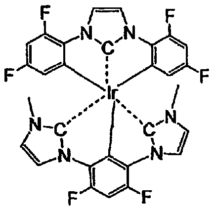
Compound (44)

Compound (41 )
C


Compound (46)

Compound (50) 4)

Compound (47) compound (51)

Compound (55)

Compound (48)

Compound (52) Compound (56)

Compound (49) Compound (53)
 57)
57)

Compound (58) (ClO4)
Compound (62)
Compound (66)

Compound (61) Compound (65)

Compound (68) (ClO4)
Compound (72)
Compound (76)

Compound (70)
Compound (74)

Compound (71) Compound (75)

Compound (82)
Compound C 86)

Compound (80) Compound (84)

Compound (81) Compound (85)

Compound (88) compound (93)
 Compound (98)

Compound (89) Compound (94)

Compound (99)

Compound (9O) Compound (95)

Compound (91) Compound (96)

Compound (92) Compound (97)

Compound (100) Compound (104)

Compound ( 1 O 1 ) Compound (105)

Compound (102) Compound (106)
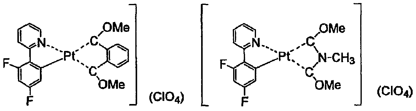
Compound (103) Compound ( 107)

Compound (118)
Compound (108) Compound (113)

Compound (109) Compound (114) Compound (119)

Compound (110) Compound (115) compound (120)


Compound (123) Compound (128)


Compound (130)

Compound (131)

Compound (127)
 ompound (137) Compound (141 )


Compound (143)

Compound (144)


Compound (145)

Compound (150) Compound (155)
Com
 pound 046) Compound (156)
Compound (151)
Co
 mpound (147) Compound (157)
Compound (152)


Compound (148) Compound (158)


Compound (149)
 Compound (159)
C
Compound (159)
C


Compound (161)

Compound 071)

Compoun (162) Compound (167)
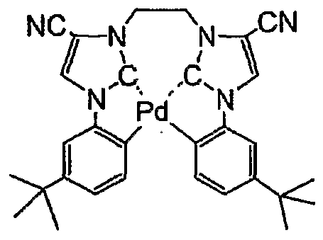 Compoun

Compound (163) Compound (168) J J Compound (173)
C


Compound (179)

Compound (184) Compound (188) Compound (192)
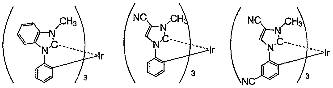
Compound (185) Compound (189) Compound (193)

Compound (186) Compound (190) Compound (194)

Compound (187) Compound (191) Compound (195)


Compound (197) Compound (201) Compound (205)

Compound (199) Compound (203) Compound (207)

Compound (208) Compound (212) Compound (216)

Compound (209) Compound (213) Compound (217)

Compound (210) Compound (214) Compound (218)
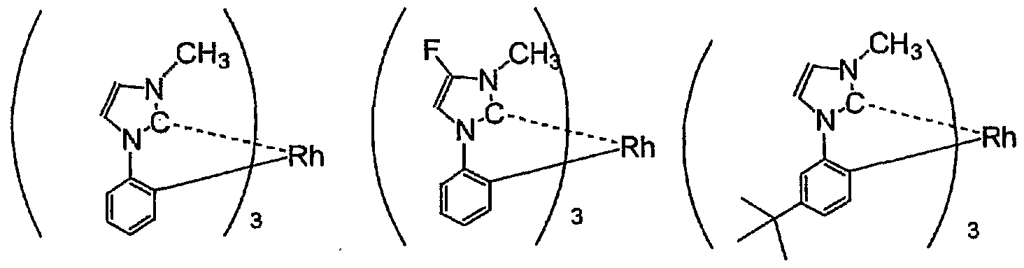
Compound (211) Compound (215) Compound (219)

Compound (220) Compound (224) Compound (228)

Compound (221) . Compound (225) Compound (229)


Compound (223) Compound (227) Compound (231)

Compound (232) Compound (236) Compound (240)

Compound (233) Compound (237) Compound (241)

Compound (234) Compound (238) Compound (242)

Compound (235) Compound (239) Compound (243)
 Compound (244)
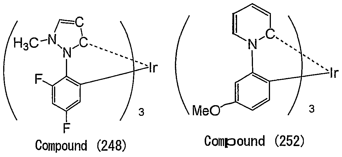
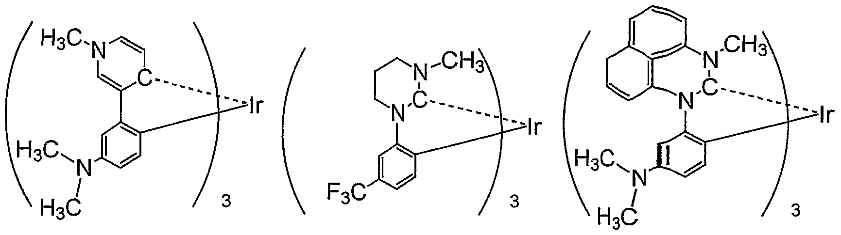
Compound (245) Compound (249) Compound (253)
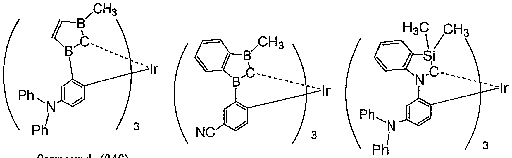
Compound (246) Compound (250)
Compound (254)

Compound (247) Compound (251)
Compound (255)

Compound (256) Compound (260) Compound (264)

Compound (257) Compound (261) Compound (265)
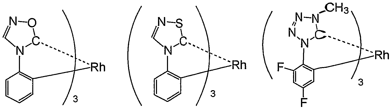
Compound (258) Compound (262) Compound (266)

Compound (258) Compound (263) Compound (267)
 Compound (268)
Compound (272) Compound (276)

Compound (271) Compound (275)
Compound (279)
The compounds according to the present invention represented by Formulas (L) to (5) can be synthesized by the use of a variety of methods. For example, by mixing a ligand or the dissociated material with a transition metal compound at a room temperature or while .heating them, the compounds can be obtained. In case of heating, a method of over-heating the materials with micro waves is effective in addition a typical heating method. Solvent (such as halogen
solvent, alcohol solvent, ether solvent, and water) or base (which may be inorganic base or organic base, examples of which can include sodium methoxy, potassium t-butoxy, triethyl amine, and potassium carbonate) may be used as needed.
For example, the synthesis of Compound (1) can be performed by the use of the following method. That is, chlorine-bridged indium complex A-I can be synthesized by the use of the method described Document 1 (J. Am. Chem. Soc. 1984, 106, 6647) or the like. Then, by nnaking a complex from complex A-I and imidazolium salt A-2 which is a precursor of a carbene ligand by the use of the reaction condition described in Document 2 (Inorg. Chem. 2004, 43, 6896) or "the like, Compound (1) can be synthesized.

A - 1 Compound ( 1 >
The synthesis of Compound (113) which is a quadridentate platinum complex can be performed by the use of the following method. That is, imidazolium salt A-3 which is a precursor of a quadridentate carbene ligand can be synthesized by the use of the method described in Document 3 (Tetrahedron, 2004, 60, 5807). Then, by making a complex from imidazolium salt A- 3 and platinum salt by the use of the reaction condition described in Document 4 (Coordination Chemistry Reviews, 2004, 248, 2247) or the like, Compound (113) can be synthesized.

A-3 Compound (113)
The compounds according to the present invention can be also synthesized by the use of the method described in Document (Angew. Chem. Lit. Ed. 2002, 41, 1290), Document 5 (".Metal Complex Chemistry," published in 1990 by Hirokawa Shoten and coauthored by Ogino Hiroshi, Matsubayasi Genetsu, and Yamamoto Yosihisa), and the like.
The compounds according to the present invention can be used as any one of a hole injecting material, a hole transporting material, a light emitting material, an electron injecting
material, an electron transporting material, a hole blocking material, an electron blocking material, an exciter blocking material and a hole injection promoting material. The compounds can be used preferably as a hole injecting material, a hole transporting material, an electron blocking material, and a light emitting material, more preferably as a hole injecting material and a light emitting material, and most preferably as a light emitting material. When the compounds are used as the light emitting material, the emission of light may be any one of emission of ultraviolet rays, emission of visible rays, and emission of infrared rays, or may be any one of emission of fluorescent light and emission of phosphorescent light. The emission of phosphorescent light is most preferable.
The maximum wavelength of phosphorescent light of the compounds according to the present invention is preferably in the range of 380nm to 490nm, more preferably in the range of 400nm to 480nm, still more preferable in the range of 410nm to 470nm, and most preferably in the range of 420nm to 460nm.
The phosphorescent quantum yield of the compounds according to the present invention is preferably 20% or more, more preferably 40% or more, and most preferably 60% or more. The phosphorescent quantum yield of the phosphorescent material can be measured at 200C by freezing and degassing a solution containing the phosphorescent material (for examples, a toluene solution of Ixl0"5 mol/1).
In the organic electroluminescent device according to the present invention, the external quantum efficiency (= (the number of input electrons) / (the number of output photons) x 100 (%)) is preferably 5% or more, more preferably 10% or more, and most preferably 13% or more. As the value of the external quantum efficiency, the maximum value of the external quantum efficiency when the device is driven at 200C may be used or the value of the external quantum efiBciency when the device is driven in the range of 100 to 300 cd/m2 at 200C may be used.
In the organic electroluminescent device according to the present invention, the internal quantum efficiency (= (external quantum efficiency) x (light extraction efficiency) / IOO (%)) is preferably 30% or more, more preferably 50% or more, and most preferably 70% or more. The light extraction efficiency of a conventional organic EL device is about 20%, but the light extraction efficiency may be set to 20% or more by devising the shape of a substrate, the shape of an electrode, the thickness of an organic layer, the thickness of an inorganic layer, the refractive index of an organic layer, the refractive index of an inorganic layer, and the like.
The organic electroluminescent device according to the present invention has at least one organic layer between a pair of electrodes of a positive electrode and a negative electrode and the organic layer is a light emitting layer or a plurality of organic layers including the light emitting layer. The organic layer may include a hole injecting layer, a hole transporting layer, an electron transporting layer, an electron transporting layer, a hole injection promoting material and a
protective layer, in addition to the light emitting layer. The respective layers may have different functions. A variety of materials may be used to form the respective layers.
Structural examples of the organic layer can include a single-layered structure (light emitting layer), a two-layered structure (light emitting layer and electron transporting layer, and hole transporting layer), a three-layered structure (electron transporting layer, light emitting layer, and hole transporting layer), a four-layered structure (electron injecting layer, light emitting layer, hole transporting layer, and hole injecting layer), and a five-layered structure (electron injecting layer, electron transporting layer, light emitting layer, hole transporting layer, and hole injecting layer).
The organic electroluminescent device according to the present invention has preferably at least three layers of the hole transporting layer, the light emitting layer, and the electron transporting layer. It is preferable that the light emitting layer includes at least two kinds of a host material and a fluorescent material.
The organic electroluminescent device according to the present invention contains a compound according to the present invention preferably in at least one layer of a light emitting layer, a layer between a light emitting layer and a negative electrode and a layer between a light emitting layer and a positive electrode, more preferably in at least one layer of a light emitting layer and a layer between a light emitting layer and a positive electrode, still more preferably in a light emitting layer.
When a compound according to the present invention is used in a light emitting layer, the light emitting layer preferably contains at least a compound according to the present invention and a light emitting material.
In a light emitting layer, a compound according to the present invention is preferably contained in 0.1 mass% to 99.5 mass%, more preferably 1 mass% to 98 mass%, particularly more preferably 5 mass% to 90 mass%.
Further, when a compound according to the present invention is contained in a layer between a light emitting layer and a negative electrode or a layer between a light emitting layer and. a positive electrode, a compound according to the present invention is preferably contained in 10 mass% to 100 mass%, more preferably 30 mass% to 100 mass%, particularly more preferably 50 mass% to 100 mass%.
The light emitting material contained in the light emitting layer is not particularly limited and can be properly selected from the known materials. Examples of the fluorescent material can include materials described in Paragraph No. 0027 of Japanese Unexamined Patent Application Publication No. 2004-146067 and materials described in Paragraph No. 0057 of Japanese Unexamined Patent Application Publication No. 2004-103577.
Examples of the phosphorescent material can include heavy metal (such as indium, platinum, rhenium, osmium, copper, and gold) complexes, and contains preferably the indium complex or the platinum complex. Specific examples thereof can include those described in Paragraph Nos. 0051 to 0057 of Japanese Unexamined Patent Application Publication No. 2004- 221068. Among them, a platinum complex having a quadridentate ligand is preferable, a platinum complex having a quadridentate ligand of which a nitrogen atom coordinates is more preferable, a platinum complex having a quadridentate ligand of which a nitrogen atom of a 6-membered heterocycle coordinates is still more preferable, and a platinum complex having a quadridentate ligand of a non-cyclic structure of which a nitrogen atom of a 6-membered heterocycle coordinates is most preferable. Examples of the platinum complex having a quadridentate ligand can include a platinum complex represented by Formula (P-I) described later. Platinum complexes having these quadridentate ligands can be synthesized by a method such as a method described in WO2004-108857A1.
The compounds according to the present invention may be used as a host material of the light emitting layer. When the compounds according to the present invention are used as the host material, the light emitting material contains preferably a platinum complex having a quadridentate ligand. The platinum complex having a quadridentate ligand is preferably a platinum complex having a quadridentate ligand of which a nitrogen atom coordinates, more preferably a platinum complex having a quadridentate ligand of which a nitrogen atom of a 6- membered heterocycle coordinates, and most preferably a platinum complex having a quadridentate ligand of a non-cyclic structure of which a nitrogen atom of a 6-membered heterocycle coordinates. Examples of the platinum complex having a quadridentate ligand can include a platinum complex represented by Formula (P-I) described later.
The compounds according to the present invention may be used in an adjacent layer of a light emitting layer (where the adjacent layer means a layer adjacent to the light emitting layer, such as a hole transporting layer, the hole injecting layer, an electron transporting layer, an electric charge blocking layer, and an exciter blocking layer). Particularly, the compounds according to the present invention are contained preferably in the adjacent layer between the positive electrode and the light emitting layer and more preferably in the hole transporting layer and/or a hole injection promoting layer. The hole injecting layer means a layer adjacent to a light emitting layer and promoting hole injection into a light emitting layer.
When the compounds according to the present invention are used in the adjacent layer of a light emitting layer, the light emitting layer contains preferably at least one compound according to the present invention, at least one light emitting material and at least one host material, or at least one host material and at least one light emitting material, and more preferably at least one host material and at least one light emitting material.
The light emitting material contained in the light emitting layer is preferably a phosphorescent material, more preferably a heavy metal complex, still more preferably heavy metal complexes, still more preferably an iridium complex or a platinum complex, and most preferably a platinum complex.
As a platinum complex, a platinum complex having a quadridentate ligand is preferable, the platinum complex having a quadridentate ligand of which a nitrogen atom coordinates is more preferable, the platinum complex having a quadridentate ligand of which a nitrogen atom of a 6- membered heterocycle coordinates is still more preferable, and the platinum complex having a quadridentate ligand of a non-cyclic structure of which a nitrogen atom of a 6-membered heterocycle coordinates is most preferable. Examples of the platinum complex having a quadridentate ligand can include a platinum complex represented by Formula (P-I) described later.
Examples of the host material contained in the light emitting layer can include the host material described later. The host material is preferably one of a heavy metal complex, a carbazole derivative, an aromatic three-degreed amine compound, and a thiophene derivative and has preferably a plurality of carbazole frameworks and/or aromatic three-degreed amine frameworks in a molecule.
Hereafter, Formula (P-I) is explained below.
Formula (P-I)

Here, Pt represents a platinum ion, L11, L12, L13, L14, and L15 represent a ligand coordinating with the platinum ion. A cyclic ligand is not formed by means of additional existence of an atom group between L11 and L14.
L15 does not form a cyclic ligand by means of the coupling to both of L11 and L14. Y11, Y12, and Y13 represent a connection group, a single bond, or a double bond. The bonds between L11 and Y12, between L12 and Y12, between L12 and Y11, between L13 and Y11, between L13 and Y13, and between L14 and Y13 represent a single bond or a double bond. nEπ represents an integer of 0 to 4.
Formula (P-I) can be expressed preferably by Formula (P-2), Formula (P-9), Formula (P-IO), Formula (P-5), and Formula (I) described below. Formula (P-2)

Here, Pt represents a platinum ion and Y21 represents a connection group, a single bond, )r a double bond. Y22 and Y23 represent a single bond or a connection bond. Q21 and Q22 •epresent an atom group constituting a nitrogen-containing heterocycle, and the bond between a ing formed by Q21 and Y21 and the bond between the ring formed by Q22 and Y21 represent a single bond or a double bond. XE21 and XE22 represent an oxygen atom, a sulfur atom, or a substituted or non-substituted nitrogen atom. RE21, RE22, RE23, and RE24 represent a hydrogen atom )r a substituent group, and RE21, RE22, RE23 5 and RE24 may form a ring by means of bonding, espectively. L25 represents a ligand coordinating with the platinum ion. nE21 represents an integer )f 0 to 4.
Formula (P-9)

Here, Pt represents a platinum ion, and QA1 and Q^ represent an atom group instituting a nitrogen-containing heterocycle. RA1, R", R*3, and RM represent a hydrogen atom >r a substituent group, and RA1 and R^2, and R*3 and RM may form a ring by means of bonding,
respectively. Y^ and Y^ represent a single bond or a connection bond. YA1 represent a connection bond, a single bond, or a double bond for connecting two bidentate ligands in a parenthesis. L^ represents a ligand coordinating with the platinum ion. nA1 represents an integer of O to 4.
Formula (P-IO)

Here, Pt represents a platinum ion, YB2 represents a connection group and YB2 and YB3 represent a connection group or a single bond. XB1 and XB2 represent an oxygen atom, a sulfur atom, or a substituted or non-substituted nitrogen atom. nB1 and nB2 represent an integer of 0 or 1. RB1, RB2, RB3, RB4, RB5, and RBδ represent a hydrogen atom or a substituent group, and RB1 and RB2, and RB3 and RB4 may form rings by means of bonding, respectively. LB5 represents a ligand coordinating with the platinum ion. nB3 represents an integer of 0 to 4. Here, YB1 is not connected to RB5 or RBδ.
Formula (P-5)

Here, Pt represents a platinum ion, and Q51, Q52, Q53, and Q54 represent an atom group constituting a nitrogen-containing heterocycle. Y51 represents a connection group, a single bond or a double bond. W51 and W52 represent a substituted or non-substituted carbon atom or nitrogen atom. L55 represents a ligand coordinating with the platinum ion. nE51 represents an integer of 0 to 4. Formula (I)

In Formula (I), Z1 and Z2 represent a nitrogen-containing aromatic 6-membered ring of which a nitrogen atom coordinates with platinum. Q represents an aromatic 5-membered ring having one or two nitrogen atoms. L1 and L2 represent a single bond or a two-valence connection group, n represents 0 or 1.
Formula (P-2) described above can be expressed preferably by Formula (P-3) described below.
Formula (P-3)

In Formula (P-3), Z31, Z32, Z33, Z34, Z35, Z36, T31, T32, T33, T34, T35, T36, T37 and T38 represent a substituted or non-substituted carbon atom or nitrogen atom. X31 and X32 represent an oxygen atom, a sulfur atom, or a substituted or non-substituted nitrogen atom.
Formula (P-9) described above can be expressed preferably by Formulas (P-6) and (P-7) described below.
Formula (P-6)

In Formula (P-6), Pt represents a platinum ion, and Q61 and Q62 represent an atom group constituting a ring. Z61, Z62, Z63, Z64, Z65, Z66, Z67 and Z68 represent a substituted or non- substituted carbon atom or nitrogen atom. Y61 represents a connection group, a single bond, or a double bond. Y62 and Y63 represent a connection group or a single bond. L65 represents a ligand coordinating with the platinum ion. n61 represents an integer of 0 to 4.
Formula (P-7)

In Formula (P-7), Pt represents a platinum ion, and Z71, Z72, Z73, Z74, Z75, and Z76 represent a substituted or non-substituted carbon atom or nitrogen atom. Y71, Y72, and Y73 represent a connection group or a single bond. R71, R72, R73, and R74 represent a hydrogen atom or a substituent group, and R71 and R72, and R73 and R74 may form rings by means of bonding, respectively. L75 represents a ligand coordinating with the platinum ion. n71 represents an integer of 0 to 4.
Formula (P-7) described above can be expressed preferably by Formula (P-11) described below.
Formula (P-I l)

Here, RC1 and RC2 represent a hydrogen atom or a substituent group., and RC3, R04, RC5, and Rc6 represent a substituent group. nC3 and nC6 represent an integer of 0 to 3 and n04 and nC5 represent an integer of 0 to 4. When RC3, R04, RC5, and RC6 are plural, the plural RC3, R04, RC5, and RC6 may be equal to or different from each other, or may form a ring by means of bonding.
Formula (P-IO) described above can be expressed preferably by Formula (P- 12) described below.
Formula (P-12)

Here, RD3 and RD4 represent a hydrogen atom or a substituent groups and RD1 and RD2 represent a substituent group. nD1 and nD2 represent an integer of 0 to 4. When RD1 and RD2 are plural, the plural RD1 and RD2 may be equal to or different from each other, or may form a ring by means of bonding. YD1 represents a vinyl group which is substituted at first and second positions, a phenylene ring, a pyridine ring, a pyrazine ring, a pyrimidine ring, or a methylene group having a carbon number of 1 to 8.
Formula (I) described above can be expressed preferably by Formul-a.s (H), (IEI), and (IV) described below.
Formula (II)

In Formula (II), Z1, Z2, and L1 are the same with those in Formula (I). RP21 and R ,]P22 represent a hydrogen atom or a substituent group, independently. Formula (TH)

In Formula (HI), Z\ Z2, and L1 are the same with those in Formula (I). RP31, RP32, and
R represent a hydrogen atom or a substituent group, independently. Formula (IV)

In Formula (IV), Z1, Z2, and L1 are the same with those in Formula (I). RP41 and RP42 represent a hydrogen atom or a substituent group, independently.
Formula (II) described above can be expressed preferably by Formula (HA) described below.
Formula (HA)

In Formula QIA), L1 represents a single bond or a two-valence connection group* . RP21, RP22, RP5\ Rp52, RP53, RP54, RP55, and RP56 represent a hydrogen atom or a substituent group* , independently.
Formula (HA) described above can be expressed preferably by Formula (IEB) described below.
Formula (IIB)

In Formula (HB), RP21, RP22, RP5\ RP52, Rrø, RP54, RP55, RP56, RP61, and RP62 represent a hydrogen atom or a substituent group, independently.
Formula (IIB) described above can be expressed preferably by Formula (HC) described below.
Formula (HC)
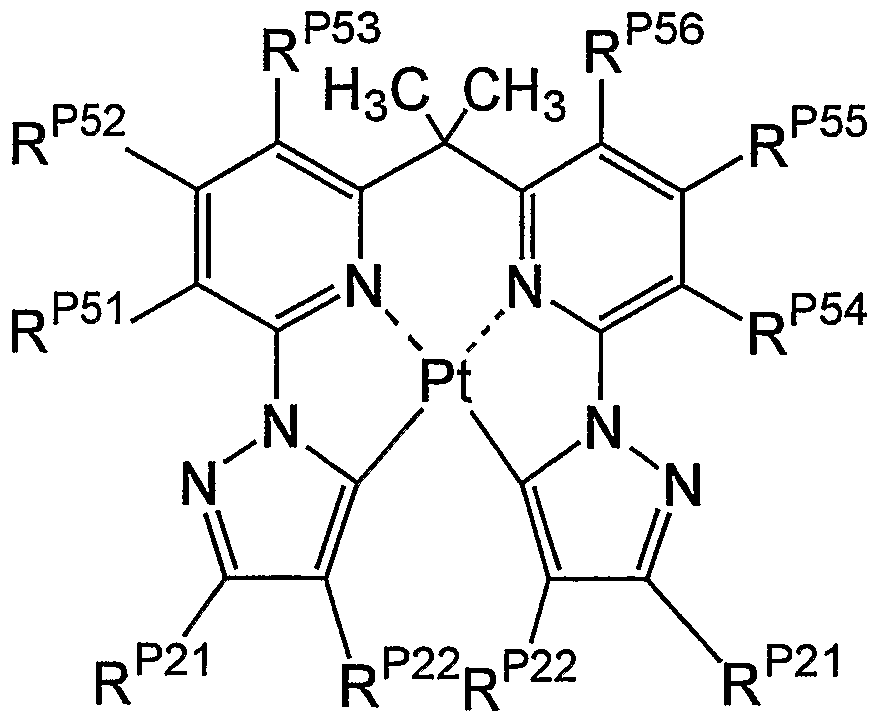
In Formula (E-C), RP21, RP22, RP51, RP52, RP53, RP54, RP55 3 and RP56 represent a hydrogen atom or a substituent group, independently.
Formula (EC) described above can be expressed preferably by Formula (IID) described below.
Formula (ED)

In Formula (IID), Rp51, RP52, RP53 5 RP54, RP55 and RP56 represent a hydrogen atom or a substituent group, independently. RP21 represents a substituent group.
Formula (P-I) is described. Pt represents a platinum ion.
L11, L12, L13, and L14 represent a ligand coordinating with the platinum ion. Ar*. atom included in L11, L12, L13, and L14 and coordinating with the platinum ion is preferably a nirtrogen atom, an oxygen atom, a sulfur atom, or a carbon atom, and more preferably a nitrogen aΛom, an oxygen atom, or a carbon atom.
The bonds between the platinum ion and L11, L12, L13, and L14 may be a covalent bond, an ion bond, or a coordinate bond. The ligands including L11, Y12, L12, Y11, L13, Y13, and IL14, respectively, are preferably an anionic ligand (of which at least one anion is bonded to metal).
The number of anions in the anionic hgand is preferably one of 1 to 3, more preferably 1 or 2, and most preferably 2
L11, L12, L13, and L14 of which a carbon atom coordinates with the platinum ion are not particularly limited, and examples thereof can include an imino hgand, an aromatic carbon-ring hgand (such as a benzene hgand, a naphthalene hgand, an anthracene hgand, and a phenanthracene hgand), and a heterocyclic hgand (such as a thiophene hgand, a pyridine hgand, a pyrazine hgand, a pyπmidine hgand, a thiazole hgand, an oxazole hgand, a pyrrole hgand, an imidazole hgand, a pyrazole hgand, condensed rings including them (such as a quinohne hgand and a benzothiazole hgand), and tautomers thereof)
Ln, L12, L13, and L14 of which a mtrogen atom coordinates with the platinum ion are not particularly limited, and examples thereof can include a nitrogen-containing heterocyclic hgand (such as a pyridine hgand, a pyrazine hgand, a pyπmidine hgand, a pyndazine hgand, a tπazine hgand, a thiazole hgand, an oxazole hgand, a pyrrole hgand, an imidazole hgand, a pyrazole hgand, a tπazole hgand, an oxadiazole hgand, a thiadiazole hgand, condensed rings including them (such as a quinoline hgand, a benzooxazole hgand, and a benzoiπudazole hgand), tautomers thereof, and an amino hgand (such as an alkyl ammo hgand (which has preferably a carbon number of 2 to 30, more preferably a carbon number of 2 to 20, and most preferably a carbon number of 2 to 10 and examples of which can include methylamino), an aryl amino hgand (such as phenylamino), an acyl ammo hgand (which has preferably a carbon number of 2 to 30, more preferably a carbon number of 2 to 20, and most preferably a carbon number of 2 to 10 and examples of which can include acetylamino and benzoylammo), an alkoxycarbonyl ammo hgand (which has preferably a carbon number of 2 to 30, more preferably a carbon number of 2 to 20, and most preferably a carbon number of 2 to 10 and examples of which can mclude methoxycarbonylamino), an aryloxycarbonyl amino hgand (which has preferably a carbon number of 7 to 30, more preferably a carbon number of 7 to 20, and most preferably a carbon number of 7 to 10 and examples of which can include phenyloxycarbonylamino), a sulfonyl ammo hgand (which has preferably a carbon number of 1 to 30, more preferably a carbon number of 1 to 20, and most preferably a carbon number of 1 to 10 and examples of which can mclude methane sulfonylamino and benzene sulfonylamino), and an imino hgand) Such hgands may be substituted again
L11, L12, L13, and L14 of which an oxygen atom coordmates with the platinum ion are not particularly limited, and examples thereof can mclude an alkoxy hgand (which has preferably a carbon number of 1 to 30, more preferably a carbon number of 1 to 20, and most preferably a carbon number of 1 to 10 and examples of which can include methoxy, ethoxy, butoxy, and 2- ethylhexyloxy), an aryloxy hgand (which has preferably a carbon number of 6 to 30, more preferably a carbon number of 6 to 20, and most preferably a carbon number of 6 to 12 and
examples of which can include phenyloxy, 1-naphthyloxy, and 2-naphthyloxy), a heterocychc oxy ligand (which has preferably a carbon number of 1 to 30, more preferably a carbon number of 1 to 20, and most preferably a carbon number of 1 to 12 and examples of which can include pyridyloxy-. pyrazyloxy, pyrimidyloxy, and quinolyloxy), an acyloxy ligand (which has preferably a carbon number of 2 to 30, more preferably a carbon number of 2 to 20, and most preferably a carbon number of 2 to 10 and examples of which can include acetoxy and benzoyloxy), a silyloxy ligand (which has preferably a carbon number of 3 to 40, more preferably a carbon number of 3 to 30, and most preferably a carbon number of 3 to 24 and examples of which can include trimethyloxy and triphenylsilyloxy), a carbonyl ligand (examples of which can include a ketone ligand, an ester ligand, and an amide ligand), and an ether ligand (examples of which can include a dialkylether ligand, a diarylether ligand, and a furyl ligand).
L11, L12, L13, and L14 of which a sulfur atom coordinates with the platinum ion are not particularly limited, and examples thereof can include an alkylthio ligand (which has preferably a carbon number of 1 to 30, more preferably a carbon number of 1 to 20, and most preferably a carbon number of 1 to 12 and examples of which can include methylthio and ethylthio), an arylthio ligand (which has preferably a carbon number of 6 to 30, more preferably a carbon number of 6 to 20, and most preferably a carbon number of 6 to 12 and examples of which can include phenylthio), a heterocyclic thio ligand (which has preferably a carbon number of 1 to 30, more preferably a carbon number of 1 to 20, and most preferably a carbon number of 1 to 12 and examples of which can include pyridylthio, 2-benzimizolylthio, 2-benzoxazolylthio, and 2- benzthiazolylthio), a thiocarbonyl ligand (such as a thioketone ligand and a thioester ligand), and a thioether ligand (such as a dialkylthioether ligand, a diarylthioether ligand, and a thiofuryl ligand). The substituent ligands may be substituted again.
L11 and L14 are preferably one of an aromatic carbon-ring ligand, an alkyloxy ligand, an aryloxy ligand, an ether ligand, an alkylthio ligand, an arylthio ligand, an alkylamino ligand, an arylamino ligand, an acylamino ligand, and a nitrogen-containing heterocyclic ligand (such as a pyridine ligand, a pyrazine ligand, a pyrimidine ligand, a pyridazine ligand, a triazine ligand, a thiazole ligand, an oxazole ligand, a pyrrole ligand, an imidazole ligand, a pyrazole ligand, a triazole ligand, an oxadiazole ligand, a thiadiazole ligand, condensed rings including them (such as a quinoline ligand, a benzooxazole ligand, and a benzimidazole ligand), and tautomers thereof), more preferably one of an aromatic carbon-ring ligand, an aryloxy ligand, an arylthio ligand, an arylamino ligand, an acylamino ligand, a pyridine ligand, a pyrazine ligand, an imidazole ligand, condensed rings including them (such as a quinoline ligand, a quinoxaline ligand, and a benzimidazole ligand), and tautomers thereof, still more preferably one of an aromatic carbon-ring ligand, an aryloxy ligand, an arylthio ligand, and an arylamino ligand, and most preferably one of an aromatic carbon-ring ligand and an aryloxy ligand.
L12 and L13 are preferably a ligand forming a coordinate bond with the platinum ion. The ligand forming a coordinate bond with the platinum ion is preferably one of a pyridine ring;, a pyrazine ring, a pyrimidine ring, a triazine ring, a thiazole ring, an oxazole ring, a pyrrole ring, a triazole ring, condensed rings including them (such as a quinoline ring, a benzooxazole ring, a benzimidazole ring, and an indolenine ring), and tautomers thereof, more preferably one of a pyridine ring, a pyrazine ring, a pyrimidine ring, a pyrrole ring, condensed rings including thein (such as a quinoline ring and a benzopyrrole ring), and tautomers thereof, and most preferably one of a pyridine ring and condensed rings including the pyridine ring (such as a quinoline ring).
L15 represents a ligand coordinating with the platinum ion. L15 is preferably a ligand. of monodentate to quadridentate and an anionic ligand of monodentate to quadridentate. The anioxήc ligand of monodentate to quadridentate is not particularly limited, but is preferably one of a halogen ligand, a 1,3-diketone ligand (such as an acetyl acetone ligand), a monoanionic bidenta~te ligand (such as a picoline acid ligand and a 2-(2-hydroxyphenyl)-pyridine ligand) containing a pyridine ligand, and a quadridentate ligand formed by L11, Y12, L12, Y11, L13, Y13, and L14, more preferably one of a 1,3-diketone ligand (such as an acetyl acetone ligand), a monoanionic bidentate ligand (such as a picoline acid ligand and a 2-(2-hydroxyphenyl)-pyridine ligand) containing a pyridine ligand, and a quadridentate ligand formed by L11, Y12, L12, Y11, L13, Y13, and L14, still more preferably one of a 1,3-diketone ligand (such as an acetylacetone ligand), and a monoanionic bidentate ligand (such as a picoline acid ligand and a 2-(2-hydroxyphenyl)-pyridin.e ligand) containing a pyridine ligand, and most preferably a 1,3-diketone ligand (such as an acetylacetone ligand). The number of dentates and the number of ligands are not greater than ttae coordination number of metal. L15 does not form a cyclic ligand by means of the coupling to both ofL11 and L14
Y11, Y12, and Y13 represent a connection group, a single bond, or a double bond. Thes connection group is not particularly limited, but is preferably a carbonyl connection group, a thiocarbonyl connection group, an alkylene group, an alkenylene group, an arylene group, a heteroarylene group, an oxygen atom connection group, a nitrogen atom connection group, a silicon atom connection group, and a group obtained by combining them. The bonds between L* n and Y12, between L12 and Y12, between L12 and Y11, between L13 and Y11, between L13 and Y13, and between L14 and Y13 represent a single bond or a double bond.
Yn, Y12, and Y13 are preferably one of a single bond, a double bond, a carbonyl connection group, an alkylene connection group, and an alkenylene group. Y11 is more preferably one of a single bond and an alkylene connection group and still more preferably an alkylene connection group. Y12 and Y13 are more preferably a single bond and an alkenylene group and still more preferably a single bond.
A ring formed by Y12, L11, L12, and a platinum ion, a ring formed by Y11, L12, L13, and a platinum ion, and a ring formed by Y13, L13, L14, and a platinum ion have preferably a ring member number of 4 to 10, more preferably a ring member number of 5 to 7, and most preferably a ring member number of 5 or 6. nEπ represents an integer of 0 to 4. When the coordination number of the platinum ion is 4, nEn is preferably 0. When the coordination number of the platinum ion is 6, nEπ is preferably 1 or 2 and more preferably 1. When the coordination number of the platinum ion is 6 and nEπ is 1, L15 represents a bidentate ligand. When the coordination number of the platinum ion is 6 and nEπ is 2, L15 represents a monodentate ligand. When nEπ is plural, plural L15 may be equal to or different from each other.
Formula (P-2) is now described.
Q21 and Q22 represent an atom group forming a nitrogen-containing heterocycle (a ring containing nitrogen coordinating with a platinum ion). The nitrogen-containing heterocycle formed by Q21 and Q22 is not particularly limited, and examples thereof can include a pyridine ring, a pyrazine ring, a pyrimidine ring, a triazine ring, a thiazole ring, an oxazole ring, a pyrrole ring, a triazole ring, condensed rings including them (such as a quinoline ring, a benzooxazole ring, a benzimidazole ring, and an indolenine ring), and tautomers thereof.
The nitrogen-containing heterocycle formed by Q21 and Q22 is preferably one of a pyridine ring, a pyrazine ring, a pyrimidine ring, a pyridazine ring, a triazine ring, a pyrazole ring, an imidazole ring, an oxazole ring, a pyrrole ring, a benzoazole ring, condensed rings including them (such as a quinoline ring, a benzooxazole ring, and a benzoimidazole ring), and tautomers thereof, more preferably one of a pyridine ring, a pyrazine ring, a pyrimidine ring, an imidazole ring, a pyrrole ring, condensed rings including them (such as a quinoline ring), and tautomers thereof, still more preferably one of a pyridine ring and a condensed ring thereof (such as a quinoline ring), and most preferably a pyridine ring.
XE21 and XE22 are preferably one of an oxygen atom, a sulfur atom, and a substituted or non-substituted nitrogen atom, more preferably one of an oxygen atom, a sulfur atom, and a substituted nitrogen atom, still more preferably one of an oxygen atom and a sulfur atom, and most preferably an oxygen atom.
Y21 is the same with Y11 described above and a preferable range thereof is also the same.
Y22 and Y23 represent a connection group or a single bond, and are preferably a single bond. The connection group is not particularly limited, but is preferably one of a carbonyl connection group, a tbiocarbonyl connection group, an alkylene group, an alkenylene group, an arylene group, a heteroarylene group, an oxygen atom connection group, a nitrogen atom connection group, and a group obtained by combining them.
The connection group is preferably one of a carbonyl connection group, an alkylene connection group, and an alkenylene connection group, more preferably one of a carbonyl connection group and an alkylene connection group, and most preferably a carbonyl connection group.
RE21, RE22, RE23, and RE24 represent a hydrogen atom or a substituent group. The substituent group is not limited, and examples thereof can include an alkyl group (which has preferably a carbon number of 1 to 30, more preferably a carbon number of 1 to 20, and most preferably a carbon number of 1 to 10, and examples of which can include methyl, ethyl, iso- propyl, tert-butyl, n-octyl, n-decyl, n-hexadecyl, cyclopropyl, cyclopentyl, and cyclohexyl), an alkenyl group (which has preferably a carbon number of 2 to 30, more preferably a carbon number of 2 to 20, and most preferably a carbon number of 2 to 10, and examples of which can include vinyl, aryl, 2-butenyl, and 3-pentenyl), an alkinyl group (which has preferably a carbon number of 2 to 30, more preferably a carbon number of 2 to 20, and most preferably a carbon number of 2 to 10, and examples of which can include propargyl and 3-pentinyl), an aryl group (which has preferably a carbon number of 6 to 30, more preferably a carbon number of 6 to 20, and most preferably a carbon number of 6 to 12, and examples of which can include phenyl, p- methylphenyl, naphthyl, and anthranil), and an amino group (which has preferably a carbon number of 0 to 30, more preferably a carbon number of 0 to 20, and most preferably a carbon number of 0 to 10, and examples of which can include amino, methyl amino, dimethyl amino, diethyl amino, dibenzyl amino, diphenyl amino, and ditolyl amino).
Other examples of the substituent group can include an alkoxy group (which has preferably a carbon number of 1 to 30, more preferably a carbon number of 1 to 20, and most preferably a carbon number of 1 to 10, and examples of which can include methoxy, ethoxy, butoxy, and 2-ethylhexyloxy), an aryloxy group (which has preferably a carbon number of 6 to 30, more preferably a carbon number of 6 to 20, and most preferably a carbon number of 6 to 12, and examples of which can include phenyloxy, 1-naphtayloxy, and 2-naphthyloxy), a heterocyclic oxy group (which has preferably a carbon number of 1 to 30, more preferably a carbon number of 1 to 20, and most preferably a carbon number of 1 to 12, and examples of which can include pyridyloxy, pyrazyloxy, pyrimidyloxy, and quinolyloxy), an acyl group (which has preferably a carbon number of 1 to 30, more preferably a carbon number of 1 to 20, and most preferably a carbon number of 1 to 12, and examples of which can include acetyl, benzoyl, formyl, and pivaloyl), an alkoxycarbonyl group (which has preferably a carbon number of 2 to 30, more preferably a carbon number of 2 to 20, and most preferably a carbon number of 2 to 12, and examples of which can include methoxycarbonyl and ethoxycarbonyl), and an aryloxycarbonyl group (which has preferably a carbon number of 7 to 30, more preferably a carbon number of 7 to
20, and most preferably a carbon number of 7 to 12, and examples of which can include phenyloxycarbonyl) .
Other examples of the substituent group can include an acyloxy group (which has preferably a carbon number of 2 to 30, more preferably a carbon number of 2 to 20, and most preferably a carbon number of 2 to 10, and examples of which can include acetoxy and benzoyloxy), an acyl amino group (which has preferably a carbon number of 2 to 30, more preferably a carbon number of 2 to 20, and most preferably a carbon number of 2 to 10, and examples of which can include acetyl amino and benzoyl amino), an alkoxycarbonyl amino group (which has preferably a carbon number of 2 to 30, more preferably a carbon number of 2 to 20, and most preferably a carbon number of 2 to 12, and examples of which can include methoxycarbonyl amino), an aryloxycarbonyl amino group (which has preferably a carbon number of 7 to 30, more preferably a carbon number of 7 to 20, and most preferably a carbon number of 7 to 12, and examples of which can include phenyloxycarbonyl amino), a sulfonyl amino group (which has preferably a carbon number of 1 to 30, more preferably a carbon number of 1 to 20, and most preferably a carbon number of 1 to 12, and examples of which can include methane sulfonyl amino and benzene sulfonyl amino), and a sulfamoyl group (which has preferably a carbon number of 0 to 30, more preferably a carbon number of 0 to 20, and most preferably a carbon number of 0 to 12, and examples of which can include sulfamoyl, methylsulfamoyl, dimethylsulfamoyl, and phenylsulfamoyl).
Other examples of the substituent group can include a carbamoyl group (which has preferably a carbon number of 1 to 30, more preferably a carbon number of 1 to 20, and most preferably a carbon number of 1 to 12, and examples of which can include carbamoyl, methylcarbamoyl, diethylcarbamoyl, and phenylcarbamoyl), an alkylthio group (which has preferably a carbon number of 1 to 30, more preferably a carbon number of 1 to 20, and most preferably a carbon number of 1 to 12, and examples of which can include methylthio and ethylthio), an arylthio group (which has preferably a carbon number of 6 to 30, more preferably a carbon number of 6 to 20, and most preferably a carbon number of 6 to 12, and examples of which can include phenylthio), a heterocyclic thio group (which has preferably a carbon number of 1 to 30, more preferably a carbon number of 1 to 20, and most preferably a carbon number of 1 to 12, and examples of which can include pyridylthio, 2-benzimizolylthio, 2-benzoxazolylthio, and 2- benzthiazolylthio), a sulfonyl group (which has preferably a carbon number of 1 to 30, more preferably a carbon number of 1 to 20, and most preferably a carbon number of 1 to 12, and examples of which can include mesyl and tosyl), a sulfϊnyl group (which has preferably a carbon number of 1 to 30, more preferably a carbon number of 1 to 20, and most preferably a carbon number of 1 to 12, and examples of which can include methane sulfinyl and benzene sulfϊnyl), and an ureido group (which has preferably a carbon number of 1 to 30, more preferably a carbon
number of 1 to 20, and most preferably a carbon number of 1 to 12, and examples of which can include ureido, methylureido, and phenylureido).
Other examples of the substituent group can include an amide phosphate group (which has preferably a carbon number of 1 to 30, more preferably a carbon number of 1 to 20, and most preferably a carbon number of 1 to 12, and examples of which can include diethyl amide phosphate and phenyl amide phosphate), an hydroxyl group, a mercapto group, a halogen atom (examples of which can include a fluorine atom, a chlorine atom, a bromine atom, and an iodine atom), a cyano group, a sulfo group, a carboxyl group, a nitro group, a hydroxamic group, a sulfino group, a hydrazino group, an imino group, a heterocyclic group (which has preferably a carbon number of 1 to 30 and more preferably a carbon number of 1 to 12 and which includes, for example, a nitrogen atom, an oxygen atom, and a sulfur atom as the hetero atom, examples of which can include imidazolyl, pyridyl, quinolyl, furyl, thienyl, piperidyl, morpholino, benzoxazolyl, benzimidazolyl, benztbiazolyl, carbazolyl, and azepinyl), a silyl group (which has preferably a carbon number of 3 to 40, more preferably a carbon number of 3 to 30, and most preferably a carbon number of 3 to 24, and examples of which can include trimethylsilyl and triphenylsilyl), and a silyloxy group (which has preferably a carbon number of 3 to 40, more preferably a carbon number of 3 to 30, and most preferably a carbon number of 3 to 24, and examples of which can include methylsilyloxy and triphenylsilyloxy). These substituent groups may be substituted again.
RE21, RE22, RE23, and RE24 are preferably groups forming a ring structure (such as a benzo condensed ring and a pyridine condensed ring) in which an alkyl group, an aryl group, and RE21 and RE22 or RE23 and RE24 are bonded, and more preferably groups forming a ring structure (such as a benzo condensed ring and a pyridine condensed ring) in which RE21 and RE22 or RE23 and RE24 are bonded.
L25 is the same with L15 described above and a preferable range thereof is also the same. nE21 is the same with nEπ described above and a preferable range thereof is also the same.
In Formula (P-2), a metal complex that the ring formed by Q21 and Q22 is a pyridine ring and Y21 is a connection group, a metal complex that the ring formed by Q21 and Q22 is a pyridine ring, Y21 is a single bond or a double bond, and XE21 and XE22 are a sulfur atom or a substituted or non-substituted nitrogen atom, or a metal complex that the ring formed by Q21 and Q22 is a nitrogen-containing five-membered heterocycle or a nitrogen-containing six-membered heterocycle having two nitrogen atoms is preferable.
Formula (P-3) is now described.
Z31, Z32, Z33, Z34, Z35, and Z36 are a substituted or non-substituted carbon atom or nitrogen atom and preferably a substituted or non-substituted carbon atom. Examples of the
substituent group on a carbon atom can include the groups described with reference to RE21. Z31 and Z32, Z32 and Z33, Z33 and Z34, Z34 and Z35, and Z35 and Z36 may be bonded to each other through connection groups, respectively, to form condensed rings (such as a benzo condensed ring and a pyridine condensed ring). Z31 and T31, and Z36 and T38 may be bonded to each other through connection groups, respectively, to form condensed rings (such as a benzo condensed ring and a pyridine condensed ring).
The substituent group on the carbon atom is preferably one of an alkyl group, an alkoxy group, an alkylamino group, an aryl group, a group forming a condensed ring (such as a benzo condensed ring and a pyridine condensed ring), and a halogen atom, more preferably one of an alkylamino group, an aryl group, and a group forming a condensed ring (such as a benzo condensed ring and a pyridine condensed ring), still more preferably one of an aryl group and a group forming a condensed ring (such as a benzo condensed ring and a pyridine condensed ring), and most preferably a group forming a condensed ring (such as a benzo condensed ring and a pyridine condensed ring).
T31, T32, T33, T34, T35, T36, T37, and T3S are preferably a substituted or non-substituted carbon atom or nitrogen atom, and more preferably a substituted or non-substituted carbon atom. The substituent group on a carbon atom can include the groups described with reference to RE21. T31 and t32, T32 and t33, T33 and t34, T35 and Z36, T36 and Z37, and t37 and t38 may be bonded to each other through connection groups, respectively, to form condensed rings (such as a benzo condensed ring).
The substituent group on the carbon atom is preferably one of an alkyl group, an alkoxy group, an alkylamino group, an aryl group, a group forming a condensed ring (such as a benzo condensed ring and a pyridine condensed ring), and a halogen atom, more preferably one of an aryl group, a group forming a condensed ring (such as a benzo condensed ring and a pyridine condensed ring), and a halogen atom, still more preferably one of an aryl group and a halogen atom, and most preferably an aryl group.
X31 and X32 are the same with XE21 and XE22 described above, respectively, and preferable ranges thereof are also the same.
Formula (P-5) is now described.
Q51 and Q52 are the same with Q21 and Q22 described above, respectively, and preferable ranges thereof are also the same.
Q53 and Q54 represent a group forming a nitrogen-containing heterocycle (a ring containing nitrogen coordinating with the platinum ion). The nitrogen-containing heterocycle formed by Q53 and Q54 is not particularly limited, but preferably one of a tautomer of a pyrrole derivative, a tautomer of an imidazole derivative, a tautomer of a thiazole derivative, and a tautomer of an όxazole derivative, more preferably one of a tautomer of a pyrrole derivative, a
tautomer of an imidazole derivative, and a tautomer of a thiazole derivative, still more preferably one of a tautomer of a pyrrole derivative and a tautomer of an imidazole derivative, and most preferably a tautomer of a pyrrole derivative.
Y51 is the same with Y11 described above and a preferable range thereof is also the same.
L55 is the same with L15 described above and a preferable range thereof is also the same. nE51 is the same with nEn described above and a preferable range thereof is also the same.
W51 and W52 are preferably a substituted or non-substituted carbon atom or nitrogen atom, more preferably a non-substituted carbon atom or nitrogen atom, and still more preferably a non-substituted carbon atom.
Formula (P-9) is now described. QA1, Q*2, YA1, Y*2, Y*3, RA1, R*2, R*3, RA4, L*5, and nA1 are the same with M21, Q21, Q22, Y21, Y22, Y23, RE21, RE22, RE23, RE24, L25, and nE21 in Formula (P-2) and preferable ranges thereof are also the same.
Formula (P -6) is now described.
Q61 and Q62 represent a group forming a ring. The ring formed by QS1 and Q62 is not limited, and examples thereof can include a benzene ring, a pyridine ring, a pyridazine ring, a pyrimidine ring, a thiophene ring, an isothiazole ring, a furan ring, an isooxazole ring, and condensed rings thereof.
The ring formed by Q61 and Q62 is preferably one of a benzene ring, a pyridine ring, a thiophene ring, a thiazole ring, and condensed rings thereof, more preferably one of a benzene ring, a pyridine ring, and condensed rings thereof, and most preferably a benzene ring and a condensed ring thereof.
Y61 is the same with Y11 and a preferable range thereof is also the same.
Y62 and Y63 represent a connection group or a single bond. The connection group is not particularly limited, and examples thereof can include a carbonyl connection group, a thiocarbonyl connection group, an alkylene group, an alkenylene group, an arylene group, a heteroarylene group, an oxygen atom connection group, a nitrogen atom connection group, and a group obtained by combining them.
Y62 and Y63 are preferably one of a single bond, a carbonyl connection group, an alkylene connection group, and an alkenylene connection group, more preferably one of a single bond and an alkenylene connection group, and most preferably a single bond.
L65 is the same with L15 described above and a preferable range thereof is also the same. n61 is the same with nEπ described above and a preferable range thereof is also the same.
Z61, Z62, Z63, Z64, Z65, Z65, Z67, and Z68 are a substituted or non-substituted carbon atom or nitrogen atom and preferably a substituted or non-substituted carbon atom. Examples of the substituent group on a carbon atom can include the groups described with reference to RE21. Z61
and Z62, Z62 and Z63, Z63 and Z64, Z65 and Z66, Z66 and Z67, and Z67 and Z68 may "be bonded to each other through connection groups, respectively, to form condensed rings (such as a benzo condensed ring and a pyridine condensed ring). The ring formed by Q61 and Q62 may be bonded to Z61 and Z68 through connection groups, respectively, to form rings.
The substituent group on the carbon atom is preferably one of an albyl group, an alkoxy group, an alkylamino group, an aryl group, a group forming a condensed ring (such as a benzo condensed ring and a pyridine condensed ring), and a halogen atom, more preferably one of an alkylamino group, aryl group, and a group forming a condensed ring (such as a benzo condensed ring and a pyridine condensed ring), still more preferably one of an aryl group aund a group forming a condensed ring (such as a benzo condensed ring and a pyridine condensed ring), and most preferably a group forming a condensed ring (such as a benzo condensed ring and a pyridine condensed ring).
Formula (P-T) is now described.
Y71, Y72, and Y73 are the same with Y62 and preferable ranges thereof are also the same.
L75 is the same with L15 described above and a preferable range thereof is also the same. n71 is the same with nEπ described above and a preferable range thereof is also the same.
Z71, Z72, Z73, Z74, Z75, and Z76 are a substituted or non-substituted carbon atom or nitrogen atom and preferably a substituted or non-substituted carbon atom. Examples of the substituent group on a carbon atom can include the groups described with reference to RE21. Z71 and Z72, and Z73 and Z74 may be bonded to each other through connection groups, respectively, to form condensed rings (such as a benzo condensed ring and a pyridine condensed ring).
R71 to R74 are the same with the substituent groups of RE21 to RE24 in .Formula (P-2) and preferable ranges thereof are also the same.
Formula (P-Il) is now described.
Rcl and RC2 are a hydrogen atom or a substituent group and examples of the substituent group preferably include an alkyl group and an aryl group described as the subs"tituent groups of RE21 to RE24 in Formula (P-2). The substituent groups representd by R03, R04. R.C5, and RC6 are the same with the substituent groups of RE21 in Formula (P-2). nC3 and nc6 are an integer of 0 to 3 and n04 and nC5 are an integer of 0 to 4. When RC3, R04, RC5, and Rc6 are plural, respectively, the plural RC3, R04, Rc5, and RC6 may be equal or different. RC3, R04, RC5, and RC6 axe preferably one of an alkyl group, an aryl group, a hetero aryl group, and a halogen atom.
Formula (P-IO) is now described.
YB2, YB3, RBI, RB2, RB3, RB4, LB5, nB3, XB1, and XB2 are the same mth Y22, Y23, RE21, RE22, RE23 5 RE24, L25, nE21, XE21, and XE22 in Formula (P-2). YB1 represents a connection group and is the same with Y21 in Formula (P-2), which is preferably one of a vinyl group which is substituted at first and second positions, a phenylene ring, a pyridine ring, a pyrazine ring, a P3τimidine ring,
and a methylene group having a carbon number of 1 to 8. RB5 and RB6 are a hydrogen atom or a substituent group, and examples of the substituent group can include an alkyl group, an aryl group, and a heterocyclic group described as the substituent groups of RE21, in Formula. (P-2). However, YB1 is not connected to RB5 or RB6. nB1 and nB2 are an integer of 0 or 1.
Formula (P- 12) is now described.
The substituent groups representd by RD1, RD2, RD3, and RD4 are the same with the substituent groups representd by RB5 or RB6 in Formula (P-IO) and preferable ranges thereof are also the same. nD1 and nD2 are an integer of 0 to 4. YD1 is a vinyl group which is substituted at first and second positions, a phenylene ring, a pyridine ring, a pyrazine ring, a p5^imidine ring, or a methylene group having a carbon number of 1 to 8.
Substituent group A in the present specification can be defined as follows in the following explanation of the compounds group.
(Substituent Group A) an alkyl group (which has preferably a carbon number of 1 to 30, more preferably a carbon number of 1 to 20, and most preferably a carbon number of 1 to 10, and examples of which can include methyl, ethyl, iso-propyl, tert-butyl, n-octyl, n-decyl, n-hexadecyl, cyclopropyl, cyclopentyl, and cyclohexyl), an alkenyl group (which has preferably a carbon number of 2 to 30, more preferably a carbon number of 2 to 20, and most preferably a carbon number of 2 to 10, and examples of which can include vinyl, aryl, 2-butenyl, and 3-pentenyl), an alkinyl group (which has preferably a carbon number of 2 to 30, more preferably a carbon number of 2 to 20, and most preferably a carbon number of 2 to 10, and examples of which can include propargyl and 3-pentinyl), an aryl group (which has preferably a carbon number of 6 to 30, more preferably a carbon number of 6 to 20, and most preferably a carbon number of 6 to 12, and examples of which can include phenyl, p-methylphenyl, naphthyl, and anthranil), an amino group (which has preferably a carbon number of 0 to 30, more preferably a carbon nuirϊber of 0 to 20, and most preferably a carbon number of 0 to 10, and examples of which can include amino, methyl amino, dimethyl amino, diethyl amino, dibenzyl amino, diphenyl amino, aaid ditolyl amino), an alkoxy group (which has preferably a carbon number of 1 to 30, more preferably a carbon number of 1 to 20, and most preferably a carbon number of 1 to 10, and examples of which can include methoxy, ethoxy, butoxy, and 2-ethylhexyloxy), an aryloxy group (which has preferably a carbon number of 6 to 30, more preferably a carbon number of 6 to 20, and most preferably a carbon number of 6 to 12, and examples of which can include phenyloxy, 1- naphtayloxy, and 2-naphthyloxy), and a heterocyclic oxy group (which has prefeiably a carbon number of 1 to 30, more preferably a carbon number of 1 to 20, and most preferably a carbon number of 1 to 12, and examples of which can include pyridyloxy, pyrazyloxy, p;yrimidyloxy, and quinolyloxy).
An acyl group (which has preferably a carbon number of 1 to 30, more preferably a carbon number of 1 to 20, and most preferably a carbon number of 1 to 12, and examples of which can include acetyl, benzoyl, formyl, and pivaloyl), an alkoxycarbonyl group (which has preferably a carbon number of 2 to 30, more preferably a carbon number of 2 to 20, and most preferably a carbon number of 2 to 12, and examples of which can include methoxycarbonyl and ethoxycarbonyl), an aryloxycarbonyl group (which has preferably a carbon number of 7 to 30, more preferably a carbon number of 7 to 20, and most preferably a carbon number of 7 to 12, and examples of which can include phenyloxycarbonyl), an acyloxy group (which has preferably a carbon number of 2 to 30, more preferably a carbon number of 2 to 20, and most preferably a carbon number of 2 to 10, and examples of which can include acetoxy and benzoylox^), an acyl amino group (which has preferably a carbon number of 2 to 30, more preferably a carbon number of 2 to 20, and most preferably a carbon number of 2 to 10, and examples of which can include acetyl amino and benzoyl amino), an alkoxycarbonyl amino group (which has preferably a carbon number of 2 to 30, more preferably a carbon number of 2 to 20, and most preferably a carbon number of 2 to 12, and examples of which can include methoxycarbonyl amino), and an aryloxycarbonyl amino group (which has preferably a carbon number of 7 to 30, more preferably a carbon number of 7 to 20, and most preferably a carbon number of 7 to 12, and examples of which can include phenyloxycarbonyl amino).
A sulfonyl amino group (which has preferably a carbon number of 1 to 30, more preferably a carbon number of 1 to 20, and most preferably a carbon number of 1 to 12, and examples of which can include methane sulfonyl amino and benzene sulfonyl amino), a. sulfamoyl group (which has preferably a carbon number of 0 to 30, more preferably a carbon number of 0 to 20, and most preferably a carbon number of 0 to 12, and examples of which can include sulfamoyl, methylsulfamoyl, dimethylsulfamoyl, and phenylsulfamoyl), a carbamoyl group (whibli has preferably a carbon number of 1 to 30, more preferably a carbon number of 1 to 20, and most preferably a carbon number of 1 to 12, and examples of which can include carbamoyl., methylcarbamoyl, diethylcarbamoyl, and phenylcarbamoyl), an alkylthio group (whicfci has preferably a carbon number of 1 to 30, more preferably a carbon number of 1 to 20, aaid most preferably a carbon number of 1 to 12, and examples of which can include methylthio and ethylthio), an arylthio group (which has preferably a carbon number of 6 to 30, more preferably a carbon number of 6 to 20, and most preferably a carbon number of 6 to 12, and examples of which can include phenylthio), a heterocyclic thio group (which has preferably a carbon nunxber of 1 to 30, more preferably a carbon number of 1 to 20, and most preferably a carbon nυmbex of 1 to 12, and examples of which can include pyridylthio, 2-benzimizolylthio, 2-benzoxazolylthio, and 2- benzthiazolylthio), and a sulfonyl group (which has preferably a carbon number of 1 to 30, more
preferably a carbon number of 1 to 20, and most preferably a carbon number of 1 to 12, an<i examples of which can include mesyl and tosyl).
A sulfinyl group (which has preferably a carbon number of 1 to 30, more prefera_bly a carbon number of 1 to 20, and most preferably a carbon number of 1 to 12, and examples of which can include methane sulfinyl and benzene sutfinyl), an ureido group (which has preferably a. carbon number of 1 to 30, more preferably a carbon number of 1 to 20, and most preferably a carbon number of 1 to 12, and examples of which can include ureido, methylureido, and phenylureido), an amide phosphate group (which has preferably a carbon number of 1 to 3O, more preferably a carbon number of 1 to 20, and most preferably a carbon number of 1 to 12, and examples of which can include diethyl amide phosphate and phenyl amide phosphate), an hydroxyl group, a mercapto group, a halogen atom (examples of which can include a fluorine atom, a chlorine atom, a bromine atom, and an iodine atom), a cyano group, a sulfo group, s. carboxyl group, a nitro group, a hydroxamic group, a sulfino group, a hydrazino group, an imino group, a heterocyclic group (which has preferably a carbon number of 1 to 30 and more pr&ferably a carbon number of 1 to 12 and which includes, for example, a nitrogen atom, an oxygen atom, and a sulfur atom as the hetero atom, examples of which can include imidazolyl, pyridyl, qn-inolyl, furyl, thienyl, piperidyl, morpholino, benzoxazolyl, benzirnidazolyl, benzthiazolyl, carbazol^l, and azepinyl), a silyl group (which has preferably a carbon number of 3 to 40, more preferably s. carbon number of 3 to 30, and most preferably a carbon number of 3 to 24, and examples odf which can include trimethylsilyl and triphenylsilyl), and a silyloxy group (which has preferably a carbon number of 3 to 40, more preferably a carbon number of 3 to 30, and most preferably a carbon number of 3 to 24, and examples of which can include methylsilyloxy andtriphenylsilyloxy). These substituent groups may be substituted again.
The groups of Substituent group A or the groups in Formulas (I), (II), (III), (TV), (HA), (HB), (HC) and (HD) described below (RP21, RP22, RP31, RP32, RP33, Rp41, RP42, RP51, RP52, RPS3, RPS4, RP55, RP56, RP61, and RP62 are preferably selected from the following group: an alkyl group having a carbon number of 1 to 20, an alkenyl group having a carbon number of 2 to 10, an aryl group having a carbon number of 6 to 20, an amino group having a carbon number of 2 to 20, an jaJkoxy group having a carbon number of 1 to 20, an aryloxy group having a carbon number of 6 to 20, an acyl group having a carbon number of 2 to 20, an alkoxycarbonyl group having a carbon nimmber of 2 to 20, an alkylthio group having a carbon number of 1 to 20, an arylthio group having a. carbon number of 6 to 20, a sulfonyl group having a carbon number of 1 to 20, a hydroxyl group, a halogen atom, a cyano group, a nitro group, and a heterocyclic group having a ring member number of 5 to 7.
The complex represented by Formula (I) is now described. In Formula (I), Z1 ancfi Z2 represent a nitrogen-containing 6-membered aromatic ring of which a nitrogen atom coordinates
with platinum. Q represents a 5-membered aromatic ring containing one or two nitrogen atom. L1 and L2 represent a single bond or a connection group, n represents 0 or 1.
Z1 and Z2 represent a nitrogen-containing 6-membered aromatic ring of which a nitrogen atom coordinates with platinum. Z1 and Z2 are preferably one of pyridine, pyrazine, pyrimidine, pyridazine, and triazine, more preferably pyridine, pyrazine, and pyrimidine, still more preferably pyridine and pyrazine, and most preferably a pyridine. Z1 and Z2 may be equal to or different from each other. Z1 and Z2 may have a substituent group selected from the groups of Substituent group A.
The substituent group which Z1 and Z2 may have is preferably an alkyl group, an aryl group, an amino group, an alkoxy group, an aryloxy group, an acyl group, an alkoxycarbonyl group, an alkylthio group, a sulfonyl group, a hydroxy! group, a halogen atom, a cyano group, a nitro group, and a heterocyclic group.
Z1 and Z2 may form a condensed ring with another ring. Examples of the ring to be condensed can include a benzene ring, a pyridine ring, a pyrazine ring, a pyrimidine ring, a pyridazine ring, a thiophene ring, a furan ring, a pyrrole ring, an imidazole ring, a pyrazole ring, a triazole ring, an oxazole ring, a thiazole ring, an oxadiazole ring, and a thiadiazole ring.
Z1 and Z2 are preferably one of a substituted or non-substituted pyridine ring, a pyrazine ring, and a pyrimidine ring, more preferably one of a non-substituted pyridine ring and a pyrazine ring, and still more preferably a non-substituted pyridine ring.
Q represents a nitrogen-containing 5-membered aromatic ring having one or two nitrogen atoms. That is, Q represents a group forming the nitrogen-containing 5-membered aromatic ring having one or two nitrogen atoms along with a carbon atom and a nitrogen atom expressed in Z^N-C-Pt (or Z2-N-C-Pt). Examples of Q can include (non-)substituted pyrrole, pyrazole, and imidazole. Q is preferably one of (non-)substituted pyrrole and pyrazole, more preferably (non-)substituted pyrazole, still more preferably pyrazole having a substituent group at the third position, still more preferably pyrazole having an alkyl group or a cyano group at the third position, and most preferably pyrazole having a trifluoromethyl group, a t-butyl group, or a cyano group.
Q may have a substituent group and the substituent group is the same with those of Substituent group A. The substituent group of Q is preferably one of an alkyl group, an aryl group, a heterocyclic group, and a cyano group, more preferably one of an alkyl group and a cyano group, and still more preferably one of a trifluoromethyl group, a t-butyl group, and a cyano group.
Q may form a condensed ring with another ring. Examples of the ring to be condensed can include a benzene ring, a pyridine ring, a pyrazine ring, a pyrimidine ring, a pyridazine ring, a thiophene ring, a furan ring, a pyrrole ring, an imidazole ring, a pyrazole ring, a triazole ring, an oxazole ring, a thiazole ring, an oxadiazole ring, and a thiadiazole ring.
L1 and L2 represent a single bond or a 2-valence connection group, n represents 0 or 1. n is preferably 0. That is, when n is 0, two Q's do not form a ring by means of bonding. The 2- valence connection group is not particularly limited, but preferably a connection group including a. carbon atom, a nitrogen atom, an oxygen atom, a sulfur atom or a silicon atom. Specific examples of the 2-valence connection group are described below, but the present invention is not limited to the examples.

These connection groups may further have a substituent group and the substituent groups of Z1 and Z2 can be used as the substituent group to be introduced
L1 is preferably one of a dialkyl methylene group, a diaryl methylene group, and diheteroaryl methylene group, more preferably one of a dimethyl methylene group and a diphenyl methylene group, and most preferably a dimethyl methylene group. L2 is preferably one of a dialkyl methylene group, a diaryl methylene group, an ethylene group, a dialkyl ethylene group, a trialkyl ethylene group, a tetraalkyl ethylene group and a tetraaryl ethylene group, more preferably one of a dialkyl methylene group, a diaryl methylene group, an ethylene group and a tetraalkyl
ethylene group, more preferably one of a dialkyl methylene group, an ethylene group and a tetraalkyl ethylene group.
The complex represented by Formula (I) is preferably a complex represented by Formula (II). In Formula (II), Z1 and Z2 represent a nitrogen-containing 6-membered aromatic ring of which a nitrogen atom coordinates with platinum. L1 represents a single bond or a 2- valence connection group. L1 is the same with that of Formula (I), and a preferable range thereof is also the same. R1"21 and RP22 represent a hydrogen atom or a substituent group, independently, and the substituent group is the same with those of Substituent group A. RP21 and RP22 substituted with the same pyrazole ring may form a condensed ring by means of connection. RP22 may form a ring by bonding to RP22 substituted with another pyrazole.
RP21 is preferably one of a hydrogen atom, a methyl group, a trifluoromethyl group, a t- butyl group, and a cyano group, more preferably one of a methyl group, a trifluoromethyl group, a t-butyl group, and a cyano group, and still more preferably one of a trifluoromethyl group, a t- butyl group, and cyano group.
RP22 is preferably one of a hydrogen atom, a methyl group, a trifluoromethyl group, a t- butyl group, a cyano group, and groups forming substituted or non-substituted methylene or ethylene by means of connection between RP22, more preferably one of a hydrogen atom, a cyano group, and groups forming substituted or non-substituted methylene or ethylene by means of connection between R1"22, still more preferably one of a hydrogen atom and groups forming substituted or non-substituted methylene or ethylene by means of connection between R1"22, and most preferably a hydrogen atom.
The complex represented by Formula (I) is preferably a complex represented by Formula (III). In Formula (III), Z1 and Z2 represent a nitrogen-containing 6-membered aromatic ring of which a nitrogen atom coordinates with platinum. L1 represents a single bond or a 2- valence connection group. L1 is the same with that of Formula (I), and a preferable range thereof is also the same. RP31, RP32, and RP33 represent a hydrogen atom or a substituent group, independently, and the substituent group is the same with those of Substituent group A. RP31 and RP32, and RP32 and RP33 may form a condensed ring by means of connection therebetween.
Examples of the condensed ring formed by connection between RP31 and RP32 and between RP32 and RP33 can include a benzene ring, a pyridine ring, a pyrazine ring, a pyrimidine ring, a pyridazine ring, a pyrrole ring, a pyrazole ring, an imidazole ring, an oxazole ring, a thiazole ring, an isothiazole ring, and an isooxazole ring. Among them, a benzene ring, a pyridine ring, a pyrimidine ring, and a pyrazine ring are preferable. The rings may be condensed with another ring.
RP31 is preferably one of a hydrogen atom, an alkyl group, an aryl group, a cyano group, and a group forming a condensed ring with RP32, more preferably one of a hydrogen atom, a
methyl group, a t-butyl group, a phenyl group, a cyano group, a trifluoromethyl group, and a group forming a condensed ring with RP32, and still more preferably one of a methyl group, a t- butyl group, and a group forming a condensed ring with RP32.
RP32 is preferably one of a hydrogen atom, an alkyl group, an aryl group, a cyano group, a group forming a condensed ring with RP31, and a group forming a condensed ring with RP33, more preferably one of a hydrogen atom, a methyl group, a t-butyl group, a phenyl group, a cyano group, a trifluoromethyl group, a group forming a condensed ring with RP31, and a group forming a condensed ring with RP33, and still more preferably one of a t-butyl group, a cyano group, a trifluoromethyl group, and a group forming a condensed ring with RP31.
RP33 is preferably one of a hydrogen atom, an alkyl group, an aryl group, a cyano group, and a group forming a condensed ring with RP32, more preferably one of a hydrogen atom, a methyl group, and a group forming a condensed ring with RP32, and still more preferably one of a hydrogen atom and a group forming a condensed ring with RP32.
The complex represented by Formula (I) is preferably a complex represented by Formula (TV). Formula (TV) is described, hi Formula (IV), Z1 and Z2 represent a nitrogen- containing 6-membered aromatic ring of which a nitrogen atom coordinates with platinum. L1 represents a single bond or a 2-valence connection group. L1 is the same with that of Formula (I), and a preferable range thereof is also the same. RP41 and RP42 represent a hydrogen atom or a substituent group, independently, and as the substituent group is used the substituent groups selected from the groups of Substituent group A. Rp41 and RP42 may form a condensed ring by means of connection therebetween. Examples of the condensed ring formed by connection between RP41 and RP42 can include a benzene ring, a pyridine ring, a pyrazine ring, a pyrimidine ring, a pyridazine ring, a pyrrole ring, a pyrazole ring, an imidazole ring, an oxazole ring, a thiazole ring, an isothiazole ring, and an isooxazole ring. Among them, a benzene ring, a pyridine ring, a pyrimidine ring, and a pyrazine ring are preferable. The rings may be condensed with another ring.
RP41 is preferably one of a hydrogen atom, an alkyl group, an aryl group, a cyano group, and a group forming a condensed ring with RP42, more preferably one of a hydrogen atom, a methyl group, a t-butyl group, a phenyl group, a cyano group, a trifluoromethyl group, and a group forming a condensed ring with RP42, and still more preferably one of a methyl group, a cyano group, and a group forming a condensed ring with RP42.
RP42 is preferably one of a hydrogen atom, an alkyl group, an aryl group, a cyano group, and a group forming a condensed ring with RP41, more preferably one of a hydrogen atom, a methyl group, a t-butyl group, a phenyl group, a cyano group, a trifluoromethyl group, and a group forming a condensed ring with RP41, and still more preferably one of a methyl group, a cyano group, and a group forming a condensed ring with RP41.
The complex represented by Formula (II) is preferably a complex represented by Formula (IIA). Formula (HA) is described. In Formula (HA), L1 represents a single bond or a 2- valence connection group. L1 is the same with that of Formula (I)5 and a preferable range thereof is also the same. RP21, RP22, RP51, RP52, RP53, RP54, RP55, and RP56 represent a hydrogen atom or a substituent group. RP21 and RP22 are the same with those of Formula (E) and preferable ranges thereof are also the same. RP51 to RP56 represent a hydrogen atom or a substituent group. The substituent groups represented by RP51 to RP56 are the same with those of Substituent group A. RP51 to RP5δ may form a condensed ring by means of connection therebetween.
RP51 and RP54 are preferably one of a hydrogen atom, an alkyl group, an aryl group, an amino group, an alkoxy group, an aryloxy group, an acyl group, an alkoxycarbonyl group, an alkylthio group, a sulfonyl group, a hydroxyl group, a halogen atom, a cyano group, a nitro group, and a heterocyclic group, more preferably one of a hydrogen atom, an alkyl group, an aryl group, a halogen atom, a cyano group, a nitro group, and a heterocyclic group, still more preferably one of a hydrogen atom, a methyl group, a t-butyl group, a trifluoromethyl group, a phenyl group, a fluorine atom, a cyano group, and a pyridyl group, still more preferably one of a hydrogen atom, a methyl group, and a fluorine atom, and most preferably a hydrogen atom.
RP53 and Rp56 have the same preferable ranges as those of RP51 and RP54
RP52 and RP55 are preferably one of a hydrogen atom, an alkyl group, an aryl group, an amino group, an alkoxy group, an aryloxy group, an alkylthio group, an arylthio group, a halogen atom, a cyano group, and a heterocyclic group, more preferably one of a hydrogen atom, an alkyl group, an aryl group, an amino group, an alkoxy group, an aryloxy group, and a heterocyclic group, still more preferably one of a hydrogen atom, a methyl group, a t-butyl group, a dimethyl amino group, a diphenyl amino group, a methoxy group, and a carbazolyl group, and most preferably a hydrogen atom.
The complex represented by Formula (IIA) is preferably a complex represented by Formula (IIB). Formula (HB) is described. In Formula (UB), RP21, RP22, RP51, RP52, Rp53, RP54, RP55, RP56, RPδl, and RP62 represent a hydrogen atom or a substituent group. RP21 and RP22 are the same with those of Formula (II) and preferable ranges thereof are also the same. RP51 to RP5δ are the same with those of Formula (DA) and preferable ranges thereof are also the same. RP61 and RP62 represent a hydrogen atom or a substituent group. The substituent groups represented by RPδl and RPδ2 are the same with those of Substituent group A. RPδl and RPδ2 are preferably one of a hydrogen atom, an alkyl group, an aryl group, a halogen atom, a cyano group, and a heterocyclic group, more preferably one of a hydrogen atom, a methyl group, a trifluoromethyl group, a phenyl group, a fluorine atom, a cyano group, and a pyridyl group, still more preferably one of a methyl group, a phenyl group, and a pyridyl group, and most preferably a methyl group.
The complex represented by Formula (ElB) is preferably a complex represented by Formula (IIC). Formula (IIC) is described. In Formula (HC), RP21, RP22, RP51, RP52, RP53, RP54 5 RP55, and RP5S represent a hydrogen atom or a substituent group. RP21 and RP22 are the same with those of Formula (II) and preferable ranges thereof are also the same. RP51 to RP56 are the same with those of Formula (ILA) and preferable ranges thereof are also the same.
The complex represented by Formula (IIC) is preferably a complex represented by Formula (IID). Formula (ItD) is described. In Formula (HD), RP51, RP52, RP53, RP54, RP55, and RP56 represent a hydrogen atom or a substituent group. RP21 is a substituent group. RP51 to RP56 are the same with those of Formula (DA) and preferable ranges thereof are also the same. RP23 are the same with those of Substituent group A. RP21 is preferably one of an alkyl group, an aryl group, an amino group, an alkoxy group, an aryloxy group, an acyl group, an alkoxycarbonyl group, an alkylthio group, a sulfonyl group, a hydroxyl group, a halogen atom, a cyano group, a nitro group, and a heterocyclic group, more preferably one of an alkyl group, an aryl group, a sulfonyl group, a halogen atom, a cyano group and a heterocyclic group, still more preferably one of a alkyl group, a perfluoroalkyl group, an aryl group, a perfiuoroaryl group, a sulfonyl group, a halogen atom, a cyano group, and a heterocyclic group, still more preferably one of a methyl group, a t-butyl group, a trifluoromethyl group, a phenyl group, a tolyl group, a pentafluorophenyl group, a mesyl group, a tosyl group, a fluorine atom, a cyano group, and a pyridyl group, still more preferably one of a methyl group, a t-butyl group, a trifluoromethyl group, and a cyano group, and still more preferably one of a t-butyl group, a trifluoromethyl group, and a cyano group.
In Formula (HD), RP51, RP53, RP54, and RP56 are all preferably a hydrogen atom.
Examples of the platinum complex which can be used for the electroluminescent device according to the present invention can include Compounds (1) to (6), Compounds (12) to (97), Compounds (138) to (140), Compounds (144) to (152), and Compounds (178) to (242) described in International Publication No. WO 2004/108859. Examples of compounds are further described below, but the present invention is not limited to the examples.

P-7 P-8 P-9


P-31 P-32 P-33


P-67 P-68 P-6


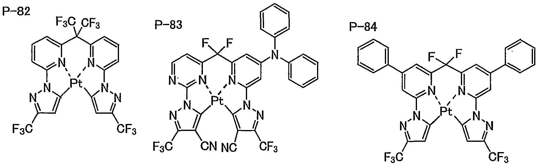


P-103 P-104 P-105

P-106 P-107 P-108


P-124 P-125 P-126
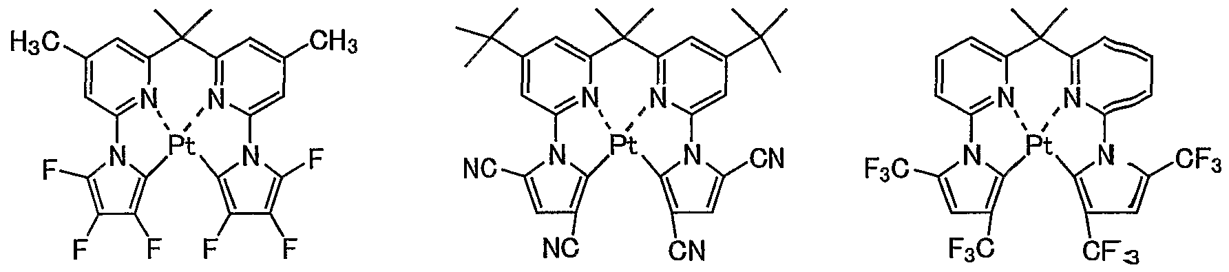

P-130 P-131 P-132


P-136 P-137 P-138

P-139 P-140 P-141

P-142 P-143 P-144
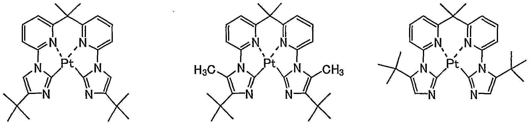

P-148 P-149 P-150


P-154 P-155 P-156


P-160 P-161 P-162


P-166 P-167 P-168


P- 172 P-173 P-174

P-175 P-176 P-177


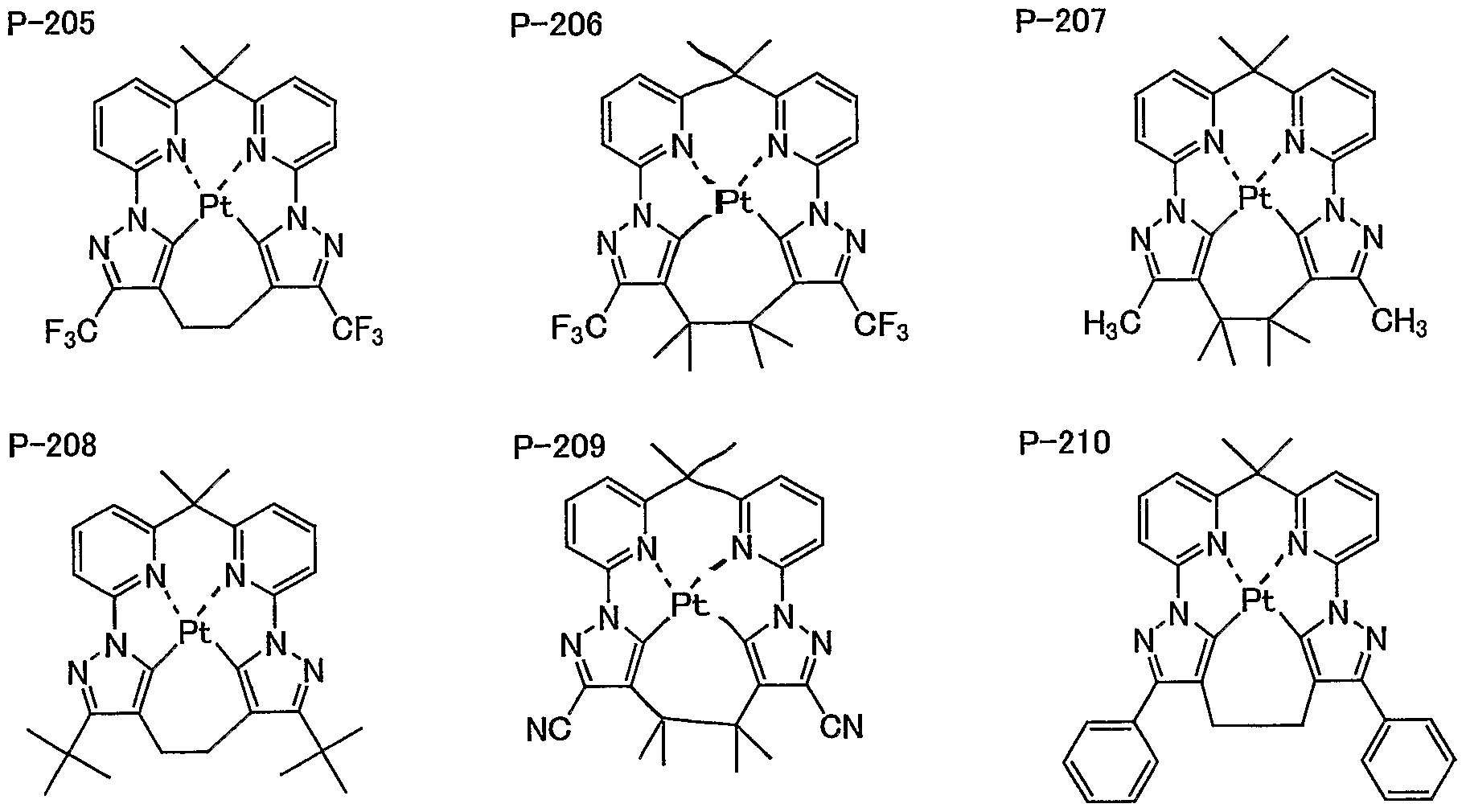
P-211 P-212 P-213


P-220 P-221 P-222


P-225 P-226 P-227

P-228 P-229 P-230

P-231 P-232 P-233

P-234 P-235 P-236


P-243 P-244 P-245

P-246 P-247 P-248


P


The electron mobility of the host material contained in the light emitting layer is preferably in the range of 1 x 10"6 cmVVs to 1 x 10"1 cm2/Vs, more preferably in the range of 5 x 10'6 cmVVs to 1 x 10'2 ciwVVs, still more preferably in the range of 1 x 10"5 cm2/Vs to 1 x 10"2 cmVVs, and most preferably in the range of 5 x 10"5 cm2/Vs to 1 x 10"2 cmVVs .
The hole mobility of the host material contained in the light emitting layer is preferably in the range of 1 x 10"6 cmz/Vs to 1 x 10"1 cmVVs, more preferably in the range of 5 x 10"6 crnVVs to 1 x 10"2 cm2/Vs, still more preferably in the range of 1 x 10"5 cnrVVs to 1 x 10~2 cm2/Vs, and most preferably in the range of 5 x 10"5 cm2/Vs to 1 x 10~2 cmYVs .
The glass transition point of the host material, the electron transporting material and the hole transporting material contained in the light emitting layer is preferably in the range of 9O0C to 4000C3 more preferably in the range of 1000C to 3800C, still more preferably in the range of 12O0C to 3700C3 and most preferably in the range of 1400C to 3600C.
In the organic electroluminescent device according to the present invention, the maximum wavelength of the emitted light is preferably in the range of 390nm to 495nm in view of blue color purity and more preferably in the range of 400nm to 490nm. The light emitting device according to the present invention may have the maximum wavelength of the emitted light in the range of 500nm and more and may be a white light emitting device.
In the organic electroluminescent device according to the present invention, the x value of CBE chromaticity of the emitted light is preferably 0.22 or less in view of the blue color purity and more preferably 0.20 or less.
In the organic electroluminescent device according to the present invention, the y value of CIE chromaticity of the emitted light is preferably in the range of 0.25 or less, more preferably 0.20 or less, and most preferably 0.15 or less.
In the organic electroluminescent device according to the present invention, the half width of an emission spectrum is preferably lOOnm or less, more preferably is 90nm or less, still more preferably 80ntn or less, and most preferably 70nm or less.
The Ti level (energy level of the least triplet excited state) of the phosphorescent material (the compounds according to the present invention and/or phosphorescent material used therewith) which can be used in the present invention is preferably in the range of 60 Kcal/mol (251.4 KJ/mol) to 90 Kcal/mol (377.1 KJ/mol), more preferably in the range of 62 Kcal/mol (259.78 KJ/mol) to 85 Kcal/mol (356.15 KJ/mol), and most preferably in the range of 65 Kcal/mol (272.35 KJ/mol) to 80 Kcal/mol (335.2 KJ/mol).
The Ti level (energy level of the least triplet excited state) of the host material contained in
the light emitting layer is preferably in the range of 60 Kcal/mol (251.4 KJ/mol) to 90 Kcal/mol (377.1 KJ/mol), more preferably in the range of 62 Kcal/mol (259.78 KJ/mol) to 85 Kcal/mol (356.15 KJ/mol), and most preferably in the range of 65 Kcal/mol (272.35 KJ/mol) to 80 Kcal/αxol (335.2 KJ/mol).
The Ti level (energy level of the least triplet excited state) of the layer (such as the hole transporting layer, the electron transporting layer, the charge blocking layer, and the exciter blocking layer) adjacent to the light emitting layer is preferably in the range of 60 Kcal/mol (251.4 KJ/mol) to 90 Kcal/mol (377.1 KJ/mol), more preferably in the range of 62 Kcal/mol (259.78 KJ/mol) to 85 Kcal/mol (356.15 KJ/mol), and most preferably in the range of 65 Kcal/mol (272.35 KJ/mol) to 80 Kcal/mol (335.2 KJ/mol).
In the organic electroluminescent device according to the present invention, the light extraction efficiency can be improved by a variety of known techniques. For example, by processing the surface shape of a substrate (for example, forming a micro uneven pattern), or controlling the refractive indexes of the substrate, the ITO layer, and the organic layer, or controlling the thickness of the substrate, the ITO layer, and the organic layer, the light extraction efficiency can be improved, thereby enhancing the external quantum efficiency.
The organic electroluminescent device according to the present invention may be of a so- called top emission type which extracts the light from the positive electrode (see Japanese Unexamined Patent Application Publication Nos. 2003-208109, 2003-248441, 2003-257651, anxl 2003-282261).
The material of the substrate used in the organic electroluminescent device according to the present invention is not particularly limited, and examples thereof can include an inorganic material such as zirconia-stabilized yttrium and glass, poly ester such as poly ethyleneterephthalate, poly butylene terephthalate, and poly ethylene naphthalate, a high-molecular material such as poly ethylene, poly carbonate, poly ethersulfone, poly arylate, aryldiglycolcarbonate, poly imide, poly cycloolefin, norbornene resin, poly (chlorotrifluoro ethylene), Teflon (registered trademark), and poly tetrafluoro ethylene-poly ethylene copolymer.
The organic electroluminescent device according to the present invention may contain a blue fluorescent compound. Alternatively, a multi-color light emitting device and a full color ligtrt emitting device may be manufactured by using a blue light emitting device containing a blue fluorescent compound and the light emitting device according to the present invention together.
In the organic electroluminescent device according to the present invention, the host material contained in the light emitting layer may be a kind or two kinds or more.
The organic electroluminescent device according to the present invention includes preferably a plurality of host materials in the light emitting layer in order to control the transport property of the hole and electron in the light emitting layer. As a plurality of host materials, a hole
transporting host material excel in the hole transport property (hole transporting host) and an electron transporting host material excel in the electron transport property (electron transporting host) can be used in combination. Here, "excel in the hole transport property" or "excel in tire electron transport property" indicates the relative relationship of a plurality of the host materials used in combination, and indicates that one of the plurality of the host materials is superior to another in the hole transport property or the electron transport property.
When a compound according to the present invention is used as the host material in a, light emitting layer, and when a compound according to the present invention is superior in the electron transport property, the compound can be used in combination with a host material excel in the hole transport property. And when a compound according to the present invention is superior inttie hole transport property, the compound can be used in combination with a host material excel in the electron transport property. -Hole transporting host- As a hole transporting host used in a light emitting layer according to the present invention, publicly known hole transporting materials can be used. For example, the following materials can be exemplified; pyrrole, carbazole, triazole, oxazole, oxadiazole, imidazole, polyarylalkane, pyrazoline, pyrazolone, phenylenediamine, arylamine, amino substituted chalkone, styryl anthracene, fluorenone, hydrazine, stilbene, silazane, aromatic tertiary amine compound, styryl amine compound, aromatic dimethylidene compound, porphyrin compound, polysilane compound, poly(N-vinylcarbazole), aniline copolymer, thiophene oligomer, conductive polymer oligomer such as polythiophene, organic silane, carbon film, and their derivatives. Among them, carbazole derivative, aromatic tertiary amine compound, thiophene derivative are preferred, particularly, those having a plurality of carbazole skeletons and/or aromatic tertiary amine akeltones in their molecules are preferred. -Electron transporting host- As an electron transporting host used in a light emitting layer according to the present invention, publicly known electron transporting materials can be used. For example, the following materials can be exemplified; pyridine, pyrimidine, triazine, imidazole, triazole, oxazole, oxadiazole, fluoreneone, anthraquinodimethane, anthrone, diphenylquinone, thiopyrandioxide-, carbodiimide, fluorenylidene methane, distyryl pyradine, fluorine substituted aromatic compound, heterocyclic tetracarboxylic acid anhydride such as naphthaleneperylene, phthalocyanine, ancl their derivatives (which may form a condensed ring with other ring) and a variety of metal complerxes represented by a metal complex of 8-quinolinol derivative, metal phthalocyanine or a metal salt which has benzoxazole or benzothiazole as ligand.
An electron transporting host is preferably metal complex, azole derivative (benzimidazole derivative, imidazopyridine derivative), azine derivative (pyridine derivative, pyrimidine
derivative, triazine derivative). Among them, with respect to the durability, metal complex is preferred in the present invention. A metal complex has a ligand containing at least one of nitrogen atom, oxygen atom and sulfur atom coordinating with a metal. A metal ion in a metal complex is not especially limited, but preferably beryllium ion, magnesium ion, aluminium ion, gallium ion, zinc ion, indium ion or tin ion, more preferably beryllium ion, aluminium ion, gallium ion or zinc ion, still more preferably aluminium ion or zinc ion.
The organic electroluminescent device according to the present invention has preferably a layer containing a compound with an ionization potential of 5.9 eV or more (more preferably 6.0 eV or more) between the negative electrode and the light emitting layer, and more preferably the electron transporting layer with an. ionization potential of 5.9 eV or more.
The method of forming the organic layer containing the compounds according to the present invention is not particularly limited, and examples thereof can include a resistance heating deposition method, an electron beam method, a sputtering method, a molecule deposition method, a coating method (such as a spray coating method, a dip coating method, an impregnation method, a. roll coating method, a gravure coating method, a reverse coating method, a roll brush method, an air knife coating method, a curtain coating method, a spin coating method, a flow coating method, a bar coating method, a micro gravure coating method, an air doctor coating method, a blade coating method, a squeeze coating method, a transfer roll coating method, a kiss coating method, a. cast coating method, an extrusion coating method, a wire-bar coating method, and a screen coating method), an inkjet method, a printing method, an LB method, and a transfer method. Among them, the resistance heating deposition method, the coating method, and the transfer method are more preferable in view of characteristics and manufacturing thereof. The layer containing the compounds according to the present invention is formed on a substrate by the use of any one method described above, but the thickness thereof is not particularly limited. The thickness is preferably IOnm or more and more preferably in the range of 50nm to 5μm.
The concentration of the transition metal complex contained in the light emitting layer is not particularly limited, but is preferably equal to or less than that of the host material which is a main component thereof, more preferably in the range of 0.1 mass% to 50 mass%, still more preferably in the range of 0.2 mass% to 30 mass%, still more preferably in the range of 0.3 mass%E> to 20 mass%, and most preferably in the range of 0.5 mass% to 10 mass%. (In this specification, mass ratio is equal to weight ratio.)
The positive electrodes serves to supply holes to the hole injecting layer, the hole transporting layer, and the light emitting layer, and may be made of metal, alloy, metal oxide, electrical conductive compound, or mixtures thereof. Among them, the material having a work function of 4 eV or more is preferable. Specific examples of the material can include conductive metal oxide such as tin oxide, zinc oxide, indium oxide, and indium-tin oxide (ITO), metal such as
gold, silver, chromium, and nickel, a mixture or stacked material of the metal and the conductive metal oxide, an inorganic conductive material such as copper iodide and copper sulfide, an organic conductive material such as poly aniline, poly thiophene, and poly pyrrole, and a stacked material of the materials and ITO. The conductive metal oxide is preferable and ITO is more preferable in view of productivity, high conductivity, an.d transparency. The thickness of the positive electrode can be properly selected depending upon tfcie materials, but is preferably in the range of lOnm to 5 urn, more preferably in the range of 50nm to lμm, and most preferably in the range of lOOnm to 500nm.
The positive electrode is generally used in the state that it is formed on a soda lime glass substrate, an alkali-free glass substrate, a transparent resin substrate, or the like. When a glass substrate is used, the material thereof is preferably the alkali-free glass so as to reduce the ions eluted from the glass. When the soda lime glass substrate is used, it is preferable that a barrier coating process with silica is performed thereto. The thickness of the substrate is not particularly limited so long as it is enough to maintain the mechanical strength thereof, but when the glass substrate is used, the thickness of the substrate is preferably 0.2mm or more and more preferably 0.7mm or more.
A variety of methods can be used to manufacture the positive electrode. For example, when the positive electrode is made of ITO, the positive electrode is formed as a film by the use of an electron beam method, a sputtering method, a resistance heating deposition method, a chemical reaction method )a sol-gel method), or a method of coating a material in which indium-tin oxide is dispersed.
By performing a cleaning process or other processes to the positive electrode, the driving voltage of the device can be decreased or tiie light emission efficiency thereof can be increased. For example, when the positive electrode is made of ITO, UV-ozone processing or plasma processing is advantageous.
The negative electrode serves to supply electrons to the electron injecting layer, the electron transporting layer, and the light emitting layer, and the material of the negative electrode is selected in consideration of the adhesion, to a layer contacting the negative electrode, such as the electron injecting layer, the electron transporting layer, and the light emitting layer, the ionization potential, and the stability. Examples of th.e material of the negative electrode can include metal, alloy, metal halide, metal oxide, conductive compounds, and mixtures thereof. The specific examples of the material can include alkali metal (such as Li, Na, and K) and fluoride or oxide thereof, alkali earth metal (such as Mg and Ca) and fluoride or oxide thereof, gold, silver, plumbum, aluminum, sodium-potassium alloy or mixture, lithium-aluminum alloy or mixture, magnesium-silver alloy or mixture, and rare earth metal such as indium and yttrium. Among them, the materials having a work function of 4 eV or less are preferable, and aluminum, lithium-
aluminum alloy or mixture, and magnesium-silver alloy or mixture are more preferable. The negative electrode may have a single-layered structure of the compound and the mixture described above, or may have a multi-layered structure including the compounds and the mixtures described above. A multi-layered structure such as aluminum/hthium fluoride and aluminum/lithium oxide is preferable. The thickness of the negative electrode can be properly selected depending upon, the materials, but is preferably in the range of IOnm to 5μm, more preferably in the range of 5θ3im to lμm, and most preferably in the range of lOOnm to lμm.
The electron beam method, the sputtering method, the resistance heating deposition method, the coating method, the transfer method, or the like can be used to manufacture the negative electrode. Two or more metals can be simultaneously deposited as simplexes. In addition, an alloy electrode may be formed by simultaneously depositing a plurality of metals and an alloy adjusted in advance may be deposited.
The sheet resistances of the positive electrode and the negative electrode are prefera-tly low and more preferably several hundreds or less Ω/D.
The light emitting layer may be made of any material as long as it has a function of injecting holes from the positive electrode, the hole injecting layer, or the hole transporting layer at the time of application of a voltage and injecting electrons from the negative electrode, the electron injecting layer, or the electron transporting layer, a function of moving the injected charge carriers, or a function of providing a place for re-coupling the holes and the electrons to emit light. Examples of the material for the light emitting layer can include a variety of metal complexes such as a rare earth complex or a metal complex of benzooxazole, benzoimidazole, benzothiazole=3 styrylbenzene, polyphenyl, diphenyl butadiene, tetraphenyl butadiene, naphthalimide, coumaLrin, perylene, perignon, oxadiazole, aldazine, pyrazine, cyclopentadiene, bisstyrylanthracene, quinacridone, pyrrolopyridine, thiadiazoropyridine, styrylamine, aromatic dimethylidine compound, and 8-quinolinol, polymer compounds such as poly thiophene, poly phenylene, aaid poly phenylene vinylene, transition metal complexes such as organic silane, iridium trisphenylpyridine complexes, and platinum forpyrine complexes, and derivatives thereof.
The light emitting material contained in a light emitting layer may be a single or two or more kinds different from each other.
The thickness of the light emitting layer is not particularly limited, but is preferably in the range of lnm to 5μm, more preferably in the range of 5nm to lμm, and most preferably in tfcie range of IOnm to 500nm.
The method of forming the light emitting layer is not particularly limited, but is preferably one of the resistance heating deposition method, the electron beam method, the sputtering method, the molecule deposition method, the coating method, the inkjet method, the printing method, "the LB method, and the transfer method, and more preferably one of the resistance heating deposition
method and the coating method.
The light emitting layer may be made of a single compound, or may be made of a plurality of compounds. The light emitting layer may have a single layer or a plurality of layers. In this case, the respective layers may emit light of different colors to emit, for example, white light. The single-layered light emitting layer may emit the white light. When the light emitting layer includes a plurality of layers, the respective layers may be made of a single compound or may be made of a plurality of compounds.
Further, in order to enhance the light emitting efficiency and improve the durability, the same light emitting materials as contained in a light emitting material can be preferably contained in a layer adjacent to the positive electrode side of the light emitting layer or a layer adjacent to the negative electrode side of the light emitting layer. Thereby, it is assumed that the charges retained in the positive electrode side's interface or the negative electrode side's interface of a light emitting layer can be effectively used for light emitting. hi addition, the present invention can employ a constitution where an energy transfer from triplet exciton to singlet exciton is used. For example, as described in JPA-2005-190949, a light emitting layer may contain a compound that emits fluorescence when a voltage is applied and a compound that has a function of amplifying a light emitting intensity during the application of a voltage by increasing the number of singlet exciton generated during the application of a voltage.
The materials of the hole injecting layer and the hole transporting layer may have any one of a function of injecting holes from the positive electrode, a function of transporting holes, and a function of blocking electrons injected from the negative electrode. Specific examples thereof can include a conductive high-molecular oligomer such as carbazole, triazole, oxazole, oxadiazole, imidazole, poly arylalkane, pyrazoline, pyrazolone, phenylenediamine, arylamine, amino- substibuted chalcone, styrylanthracene, fluorenone, hydrazone, stilbene, silazane, aromatic third- degree amine compound, styryl amine compound, aromatic JIMECHIRI DIN compound, porphyrin compound, poly silane compound, poly(N-vinylcarbazole), aniline copolymer, thiophene oligomer, and poly thiophene, an organic silane, a carbon film, the compounds according to the present invention, and derivatives thereof. The thickness of the hole injecting layer is not particularly limited, but is preferably in the range of lnm to 5μm, more preferably in the range of lnm to lOOnm, and most preferably in the range of lnm to lOnm. The thickness of the hole transporting layer is not particularly limited, but is preferably in the range of lnm to 5μm, more preferably in the range of 5nm to 1 μm, and most preferably in the range of lOnm to 500nm. The hole injecting layer and the hole transporting layer may have a single-layered structure including one or two or more kinds of the above-mentioned materials, or may have a multi-layered structure including a plurality of layers with a composition of like or different kinds.
When the hole injecting layer and the hole transporting layer are multi-layered structures,
assuming that an ionization potential of a light emitting layer is IpO, of the hole injecting layer and the hole transporting layer, an ionization potential of a layer adjacent to a light emitting layer is IpI, an ionization potential of a layer located in n-th position, from a light emitting layer side is Ipn, the relation represented by the following numeral formula (1) is preferably satisfied with respect to the low-voltage driving. Numeral formula (1): IpO > IpI > Ip2 >— > Ipn-1 > Ipn (n represents an integer of 2 or more.)
In the hole injecting layer and the hole transporting layer of an organic EL device according to the present invention, an electron receptive dopant can be contained. As an electron receptive dopant introduced into the hole injecting layer or tke hole transporting layer, inorganic compounds or organic compounds may be used as long as they are electron receptive and have a property of oxidizing an organic compound.
In particular, inorganic compounds include metal halide, such as ferric chloride, aluminum chloride, gallium chloride, indium chloride and antimony perrtachloride, and metal oxide, such as vanadium pentoxide, molybdic anhydride.
When the electron receptive dopant is an organic compound, compound having nitro group, halogen, cyano group or trifluoromethyl group etc. as substituent, quinone compound, acid anhydride compound and fullerene can be preferably used.
In addition to the above, compounds described in JP^A-06-212153, JPA-11-111463, JPA- 11-251067, JPA-2000-196140, JPA-2000-286054, JPA-20O O-315580, JPA-2001-102175, JPA- 2001-160493, JPA-2002-252085, JPA-2002-56985, JPA-2003-157981, JPA-2003-217862, JPA- 2003-229278, JPA-2004-342614, JPA-2005-72012, JPA-2005-166637, JPA-2005-029643 can be preferably used.
These electron receptive dopants can be used solely or in two or more kinds. Amount of the electron receptive dopant varies with the type of materials, however it is preferably 0.01 mass% to 50 mass%, more preferably 0.05 mass% to 2 O mass%, particularly more preferably 0.1 mass% to 10 mass% with respect to the hole transporting layer materials. The vacuum deposition method, the LB method, the coating method using the material of the hole injecting layer and the hole transporting layer dissolved or dispersed in. a solvent, the inkjet method, the printing method, or the transfer method can be used to form the hole injecting layer and the hole transporting layer. When the coating method is used, the material can be dissolved or dispersed along with a resin component. Examples of the resin component can include poly vinyl chloride, poly carbonate, poly styrene, poly methlymethacrylate, poly fcmtylmethacrylate, poly ester, poly sulfon, poly phenyleneoxide, poly butadiene, poly (N-vinylcaarbazole), hydrocarbon resin, ketone resin, phenoxy resin, poly amide, ethyl cellulose, vinyl acetate, ABS resin, poly urethane, melamine resin, unsaturated polyester resin, alkyd resin, epoxy resin, and silicon resin.
The materials for the electron injecting layer and the electron transporting layer may have
any one of a function of injecting electrons from the negative electrode, a function of transporting electrons, and a function of blocking holes injected from the positive electrode. Specific examples thereof can include a variety of metal complexes such as metal complexes of aromatic tetracarbonic acid anhydride such as triazole, oxazole, oxadiazole, imidazole-, fluorenone, anthraquinodimethane, anthrone, diphenyl quinone, thiopyrandioxide, carbodimide, fluorenyhdene methane, distyrylpyrazine, naphthalene, and perylene, metal complexes of ptthalocyanine and 8- quinolinol, and metal complexes having metal phthalocyanine, benzooxazole., or benzothiazole as a ligand, organic silane, and derivatives thereof. The thickness of the electron injecting layer and the electron transporting layer are not particularly limited, but are preferably in the range of lnm to 5μm, more preferably in the range of 5nm to lμm, and most preferably in the range of lOnm to 500nm. The electron injecting layer and the electron transporting layer may liave a single-layered structure including one or two or more kinds of the above-mentioned materials, or may have a multi-layered structure including a plurality of layers with a composition of l±ke or different kinds.
When the electron injecting layer and the electron transporting layer axe multi-layered structures, assuming that an electron affinity of a light emitting layer is EaO, an electron affinity of the electron, transporting layer adjacent to a light emitting layer is EaI, an electron affinity of the electron transporting layer located in n-th position from a light emitting layer side is Earn, the relation represented by the following numeral formula (2) is preferably satisfied with respect to the low-voltage driving. Numeral formula (2): EaO < EaI < Ea2 <•••< Eam-1 < Earn (m represents an integer of 2 or more.)
The electron injecting layer or the electron transporting layer of an oxganic EL device according to the present invention, an electron donating dopant can be contained. As an electron donating dopant introduced into the electron injecting layer or the electron transporting layer, those having properties of electron donating ability and reducing organic compounds can be used. For example, aLkaline metals such as Li, alkali earth metals such as Mg, transition metals including rare earth metals, and reductive organic compounds, etc are preferably used. As -the metals, metals which have work function of 4.2eV or below are preferable, in particular Li, "Na, K, Be, Mg, Ca, Sr, Ba, Y, Cs, La, Sm, Gd and Yb, etc are exemplified. As the reductive organic compounds, nitrogen-containing compound, sulfur-containing compound and phosphor-containing compound are exemplified.
In addition to the above, materials described in JPA-06-212153, JPA^-2000-196140, JPA- 2003-68468, JPA-2003-229278, JPA-2004-342614, etc. can be preferably u_sed.
These electron donating dopants can be used solely or in two or more kinds.
Amount of the electron donating dopant varies with the type of materials, however it is preferably 0.01 mass% to 99 mass%, more preferably 1.0 mass% to 80 mass%, particularly more preferably 2.0 mass% to 70 mass% with respect to the electron transporting layer materials.
The vacuum deposition method, the LB method, the coating method using the material of the electron injecting layer and the electron transporting layer dissolved or dispersed in a solvent, the inkjet method, the printing method, or the transfer method can be used to form the electron injecting layer and the electron transporting layer. When the coating method is used, the material can be dissolved or dispersed along with a resin component. Examples of the resin componeπet can include the materials exemplified for the hole injecting layer and the hole transporting layer.
A material of the protective layer may have a function of preventing a material of promoting device deterioration such as moisture and oxygen from entering the device. Specific examples thereof can include metal such as In, Sn, Pb, Au, Cu, Ag, Al, Ti, and Ni, metal oxide such as MgO, SiO, SiO2, Al2O3, GeO, NiO, CaO, BaO, Fe2O3, Y2O3, and TiO2, metal fluoride such as MgF2, LiF, AlF3, and CaF2, nitride such as SiNx and SiOxNy, poly ethylene, poly propylene, poly methylrnethacrylate, poly imide, poly urea, poly tetrafluoroethylene, poly chlorotrifluoroehtylene, poly dichlorodifluoroethylene, a copolymer of chlorotrifluoroethylene and dichlorodifluoroethylene, a copolymer obtained by copolymerizing tetrafluoroethylene and monomer mixture including at least one kind of co-monomer, fluorine-containing copolymer having a cyclic structure in a copolymer main chain, a water absorbing material having a water absorption rate of 1% or more, and a moisture-resistant material having a water absorption rate of 0.1% or less. The method of forming the protective layer is not particularly limited, and examples thereof can include the vacuum deposition method, the sputtering method, the reactive spattering method, an MBE (molecular beam epitaxy) method, a cluster ion beam method, an ion plating method, a plasma polymerization method (high-frequency excited ion plating method), a plasma CVD method, a laser CVD method, a thermal CVD method, a gas source CVD method, the coating method, the printing method, and the transfer method.
La an organic EL device according to the present invention, a charge generating layer may be provided between a plurality of light emitting layers in order to enhance the light emitting efficiency.
The charge generating layer has a function of generating charges (hole and electron) during the application of a voltage, in addition, it has a function of injecting the generated charges into a layer adjacent to the charge generating layer.
Any materials can be used for the material which forms the charge generating layer as long as they have above mentioned functions. The material may be formed by single compound or a plurality of compounds. In particular, those having conductive property, those having semi- conductive property as a doped organic layer or those having electrical insulating property may be used. Materials described in JPA-11-329748, JPA-2003-272860 or JPA-2004-39617 are exemplified.
In more particular, transparent conductive material such as ITO or IZO (indium zin oxxide),
organic conductive material such as fullerene, for example C60, or oligo thiopherie, organic conductive material such as metal phthalocyanin, non-metal phthalocyanin, metal porphyrin or non-metal porphyrin, metal material such as Ca, Ag, Al, alloy of Mg: Ag, alloy of Al:Li or alloy of Mg:Li, hole conductive material, electron conductive material and mixture thereof can be used.
As the hole conductive material, for example, hole transporting organic material such as 2- TNATA or NPD in which oxidizing agent having electron extracting property such as F4-TCNQ, TCNQ, FeCL3 is doped, P-type conductive polymer or P-type semiconductor are exemplified. As the electron conductive material, electron transporting organic material in which metal or metal compound having a work function of less than 4.OeV is doped, N-type conductive polymer or N- type semiconductor are exemplified. N-type semiconductor includes N-type Si, N-type Cds and N- type Zns etc. and P-type semiconductor includes P-type Si, P-type CdTe and P-type Cuo etc. Electrical insulating materials such as V2O5 can be used as the charge generating; layer.
The cliarge generating layer may be single layer or a plurality of laminated layers. As constitutions of a plurality of laminated layers, a constitution in which a material having conductive property such as transparent conductive material and metal material, and a hole conductive material or a electron conductive material are laminated, and a constitution in which the hole conductive material and the electron conductive material are laminated are exemplified.
The thickness and materials of the charge generating layer are preferably selected whereby the charge generating layer has 50% or more transmittance of visible light in general. The thickness thereof is not especially limited, but it is preferably 0.5 to 200nm, more preferably 1 to lOOnm, still more preferably 3 to 50nm and particularly more preferably 5 to 30nm.
The method for forming a charge generating layer is not especially limited. The above mentioned method for forming an organic compound layer can be employed.
Although the charge generating layer is constituted between the two or imore layers of light emitting layers, a cathode and an anode side of the charge generating layer may include materials which have a function of injecting charges into layers adjacent to the charge generating layer.
In order to enhance the injection property of electrons into the layer adjacent to the cathode side, it is preferred that electron injecting compounds, such as BaO, SrO, Li2O, LiCl, LiF, MgF2, MgO and CaP2 are laminated on the cathode side of the charge generating layer.
Li addition to the content described above, it is possible to select materials for the charge generating layer, based on the descriptions of JPA-2003-45676, US Patent No.6337492, US Patent No.6107734 and US Patent No.6872472 etc.
The applications of the organic electroluminescent device according to trαe present invention are not particularly limited, but it may be used very suitably in the fields such as display devices, displays, backlights, electronic photographs, lighting light sources, recorrding light sources, exposing light sources, reading light sources, signboards, interiors, optical
communications. The compounds according to the present invention represented by ForEtmlas (1) to (5) can be used for medical applications, fluorescent brightening agents, photograph materials, UV absorbing materials, laser pigments, recording medium materials, inkjet pigments, color filter pigments, color-changing filters, and the like.
Example
Hereinafter, embodiments of the present invention will be described, but the present invention is not limited to the embodiments described below. Synthesis of Compound (184)

Imidazolium salt-1 Compound (184)
In the flow of nitrogen, potassium hexamethyldisilazid (1.55g; 7.4 mmol) was added to a toluene (200ml) suspended liquid of imidazolium salt-1 (2.64g; 7.4 mmol), iridium (I) cfcrnloride 1, and 5-cyclooctadiene complex dimer (0.62g; 0.92 mmol) at a room temperature, and the mixture solution was heated and stirred in reflux for 15 hours. Then, the mixture solution was cooled to the room temperature. Thereafter, the solvent was removed by evaporation and the residue was refined by the use of silica gel column chromatography (hexane/chloroform = 1/1), obtaining pcrwders. The obtained powders were melted in chloroform and hexane was added thereto for crystallization, thereby obtaining Compound (184) of 1.17g. The yield was 64%. Here, 1H-NMR(CDCl3) 300MHz : δ 8.11 (d, 3H), 7.92 (d, 3H), 7.20 - 7.30 (m, 6H), 7.09 (dd, 3H), 6.98 (dd, 3H-), 6.66 - 6.78 (m, 9H), 6.53 (d, 3H), 6.40 (d, 3H), 6.20 - 6.30 (m, 6H). Synthesis of Compound (185)

Imidazolium salt-2 fac-body/mer-body mixture fac-body Compound (185)
In the flow of nitrogen, potassium hexamethyldisilazid (2.5Og; 11.9 mtnol) was added to a xylene (300ml) suspended liquid of imidazolium salt-2 (4.0Og; 11.9 mmol), indium (I) chloride 1, and 5 -cyclooctadiene complex dimer (l.l lg; 1.65 mmol) at a room temperature, and the mixture solution was heated and stirred in reflux for 6 hours. Then, the mixture solution was cooled to the room temperature. Thereafter, the solvent was removed by evaporation, and the residue was refined by the use of silica gel column chromatography (hexane/chloroform = 1/1), obtaining powders of 1.16g. The obtained powders of 0.84g were added to glycerol (10ml) and were stirred in the reflux of nitrogen for 10 hours. After cooling to the room temperature, methanol (30nύL) was added to the reaction solution and powders were extracted therefrom and filtered. The powdecrs were melted in chloroform and hexane was added thereto for crystallization, thereby obtaining Compound (185) of 0.77g. The yield was 29%. Here, 1H-NMR(CDCl3) 300MHz : δ 8.13 (A, 3H), 7.86 (d, 3H), 7.11 - 7.35 (m, 9H), 7.07 (dd, 3H), 6.73 (dd, 3H), 6.64 (d, 3H), 3.27 (s, 9H). Synthesis of Compound (208)

In the flow of nitrogen, potassium hexamethyldisilazid (3.84g; 18.3 mmol) was added, to a mesitylene (200ml) suspended liquid of imidazolium salt-1 (6.55g; 18.3 mmol), indium (I) chloride 1, and 5 -cyclooctadiene complex dimer (LOOg; 2.02 mmol) at a room temperature, acid the mixture solution was heated and stirred in reflux for 15 hours. Then, the mixture solution wa-s cooled to the room temperature. Thereafter, the solvent was removed by evaporation, and th& residue was refined by the use of silica gel column chromatography (hexane/chloroform = 1/1 ), obtaining Compound (208) of 1.04g as solid. The yield was 29%. Here, 1H-ISIMR(CDCl3) 300MHz : δ 8.12 (d, 3H), 7.92 (d, 3H), 7.20 - 7.30 (m, 6H), 6.97 - 7.12 (m, 6H)5 6.65 - 6.81 (m, 9H), 6.44 - 6.53 (m, 6H), 6.19 - 6.30 (m, 6H). [Comparative Example 1]
A cleaned ITO substrate is placed into a vapor deposition apparatus and is coated with copper phthalocyanine with a thickness of lOnm. NPD(N,N'-di-α-naphthyl-N,N'-diphenyl- benzidine) is deposited thereon with a thickness of 40nm. Ir(ppy)3 and CBP(4,4-N,N' dicarbazole- biphenyl) are deposited on the resultant structure with a ratio (mass ratio) of 5:95 with a thickness
of 30nm. BAIq is deposited thereon with a thickness of lOnm, and then AIq (tris(8- hydroxyquinoline) aluminum complex) is deposited thereon with a thickness of 30nm. Thereafter, by installing a patterned mask (light-emitting area of 4mmx5mm) on the resultant organic thin film, depositing lithium fluoride thereon with a thickness of 3nm, and then depositing aluminum thereon with a thickness of lOOnm, an EL device is manufactured. As a result of applying a DC steady voltage to the EL device to emit light by the use of Source Measure Unit 2400 made by Toyo Corporation, the green light could be obtained.

•r(ppy)3
[Example 1]
By using Compound (1) according to the present invention instead of Ir(ppy)3 in the light emitting device according to Comparative Example 1, a device is manufactured similarly to Comparative Example 1. The resultant device could be decreased to a half in the number of dark; spots generated in comparison with the device according to Comparative Example 1, thereby reducing the driving voltage for allowing current of 1 mA to flow in the EL device. [Example 2]
By using Ir(ppy)3, CBP(4,4-N,N' dicarbazole-biphenyl), and Compound (113) according to the present invention with a ratio (mass ratio) of 5:70:25, instead of Ir(ppy)3 and CBP(4,4-N,N' dicarbazole-biphenyl) in the light emitting device according to Comparative Example 1, a device ds manufactured similarly to Comparative Example 1. The resultant device could be decreased to a. half in the number of dark spots generated in comparison with the device according to ComparatrΛre Example 1, thereby reducing the driving voltage for allowing current of 1 mA to flow in the EL device. [Example 3]
By using Ir(ppy)3 and Compound (184) according to the present invention with a ratio (mass ratio) of 1:2, instead of Ir(ppy)3 and CBP(4,4-N,N' dicarbazole-biphenyl) in the light emitting device according to Comparative Example 1, a device is manufactured similarly to Comparative Example 1. The resultant device could be decreased to a half in the number of dark spots generated in comparison with the device according to Comparative Example 1, thereby reducing the driving voltage for allowing current of 1 mA to flow in the EL device. [Comparative Example A-O]
A cleaned ITO substrate was placed into a vapor deposition apparatus and NPD ((N,N'-di- α-naphthyl-N,N'-diphenyl)-benzidine) was deposited thereon as a hole transporting layer with a thickness of lOnm. Ir(ppy)3 as a light emitting material and CBP (4,4-N,N'-dicarbazolbiphenyl) as a host material were deposited on the resultant structure at a ratio (mass ratio) of 5:95 with a thickness of 30nm and BAIq was deposited thereon as an electron transporting layer with a thickness of 40nm. Thereafter, a patterned mask (of which the light emitting area is 4mmx5mm) was placed on the obtained organic thin film, lithium fluoride was deposited thereon with a thickness of about lnm, and then aluminum was co-deposited thereon with a thickness of lOOnm, thereby manufacturing an EL device. As a result of applying a DC steady voltage to the EL device to emit light by the use of Source measure unit 2400 made by Toyo Corporation, green light resulting from Ir(ppy)3 could be obtained. An EL external quantum yield calculated from the driving voltage and the front brightness of the EL device at 2000cd/m2 is shown in Table 1.

2-TNATA

BAIq
[Example A-I]
By using Compound (5) according to the present invention instead of the hole transporting layer NPD in the EL device according to Comparative Example A-O, an EL device was manufactured similarly to Comparative Example A-O. An EL external quantum yield calculated from the driving voltage and the front brightness of the EL device at 2000cd/m2 is shown in Table 1. [Example A-2]
By using Compound (185) according to the present invention instead of the hole transporting layer NPD in the EL device according to Comparative Example A-O, an EL device was manufactured similarly to Comparative Example A-O. An EL external quantum yield calculated from the driving voltage and the front brightness of the EL device at 2000cd/m2 is shown in Table 1. [Example A-3]
By using Compound (208) according to the present invention instead of the hole transporting layer NPD in the EL device according to Comparative Example A-O, an EL device was manufactured similarly to Comparative Example A-O. An EL external quantum yield calculated from the driving voltage and the front brightness of the EL device at 2000cd/m2 is shown in Table 1.
Table 1: Driving voltage and EL external quantum yield of the obtained devices at 2000cd/m2

As can be seen apparently from Table 1, the EL devices using the compounds according to the present invention as the hole transporting layer exhibit relatively high light emission efficiency in comparison with the EL device according to the comparative example, and the voltage values with the same brightness are equal to or smaller than that of the EL device according to Comparative Example A-O from the view point of improvement in light emission efficiency. [Comparative Example B-O]
A cleaned ITO substrate was placed into a vapor deposition apparatus, 2-TNATA was deposited thereon as a hole injecting layer with a thickness of 140nm. NPD ((N,N'-di-α-naphthyl- N,N'-diphenyl)-benzidine) was deposited thereon as a hole transporting layer with a thickness of 7nm. Carbazole .derivative (1) was deposited thereon as a hole injection promoting layer with a thickness of 3nm. Firpic as a light emitting material and mCP as a host material were deposited on
the resultant structure at a ratio (mass ratio) of 8:92 with a thickness of 30nm and BAIq was deposited thereon as an electron transporting layer with a thickness of 40nm. Thereafter, a patterned mask (of which the light emitting area is 4mmx5mm) was placed on the obtained organic thin film, lithium fluoride was deposited thereon with a thickness of about lnm, and then aluminum was co-deposited thereon with a thickness of lOOnm, thereby manufacturing an EL device. As a result of applying a DC steady voltage to the EL device to emit light by the use of Source measure unit 2400 made by Toyo Corporation, blue-green light resulting from Firpic could be obtained. An EL external quantum yield calculated from the driving voltage and the front brightness of the EL device at 600cd/m2 is shown in Table 2.

2-TNATA

Carbazole derivative (1)

[Example B-I]
By using Compound (5) according to the present invention instead of NPD of 7nm as the hole transporting layer in the EL device according to Comparative Example B-O, an EL device was manufactured similarly to Comparative Example B-O. An EL external quantum, yield calculated from the driving voltage and the front brightness of the EL device at 600cd/m2 is sliown in Table 2. [Example B-2]
By using Compound (185) according to the present invention instead of NTD of 7nm as the hole transporting layer in the EL device according to Comparative Example B-O, an EL device was manufactured similarly to Comparative Example B-O. An EL external quantum yield calculated from the driving voltage and the front brightness of the EL device at 600cd/m2 is sliown in Table 2. [Example B-3]
By using Compound (208) according to the present invention instead of NPD of 7nm as the hole transporting layer in the EL device according to Comparative Example B-O, an EL device was
manufactured similarly to Comparative Example B-O. An EL external quantum yield calculated from the driving voltage and the front brightness of the EL device at 600cd/m2 is shown in Table 2.
Table 2: Driving voltage and EL external quantum yield of the obtained devices at 600cd/m2

As can be seen apparently from Table 2, the EL devices using the compounds according to the present invention as the hole transporting layer exhibit relatively high light emission efficiency in comparison with the EL device according to the comparative example, and the voltage values with the same brightness are equal to or smaller than that of the EL device according to Comparative Example B-O from the view point of impπrvement in light emission efficiency. [Comparative Example C-O]
A cleaned ITO substrate was placed into a vapor deposition apparatus, 2-TNATA was deposited thereon as a hole injecting layer with a thickness of 140nm. NPD ((N,N'-di-α-naphthyl- N,N'-diphenyl)-benzidine) was deposited thereon as a hole transporting layer with a thickness of 7nm. Carbazole derivative (1) was deposited thereon as a hole injection promoting layer with a thickness of 3nm. Compound (P-2) as a light emitting material (P-2) and mCP as a host material were deposited on the resultant structure at a ratio (mass ratio) of 15:85 with a thickness of 30nm and BAIq was deposited thereon as an electron transporting layer with a thickness of 40nm. Thereafter, a patterned mask (of which the light emitting area is 4mmx5mm) was placed on the obtained organic thin film, lithium fluoride was deposited, thereon with a thickness of about lnm, and then aluminum was co-deposited thereon with a thickness of lOOnm, thereby manufacturing an EL device. As a result of applying a DC steady voltage to the EL device to emit light by the use of Source measure unit 2400 made by Toyo Corporation, blue light resulting from the light emitting material (P-2) could be obtained. An EL external quantum yield calculated from the driving voltage and the front brightness of the EL device at 400cd/m2 is shown in Table 3.

Carbazole derivative (!)
2-TNATA

Light emitting material (P-2)
BAIq
[Example C-I]
By depositing Compound (5) according to the present invention with a thickness of IOnm instead of NPD of 7nm as the hole transporting layer and Car"bazole derivative 1 of 3 nm as the hole injection promoting layer 1 in the EL device according to Comparative Example C-O, an EL device was manufactured similarly to Comparative Example C-O. An EL external quantum yield calculated from the driving voltage and the front brightness of the EL device at 400cd/m2 is shown in Table 3. [Example C-2]
By depositing Compound (185) according to the present invention with a thickness of IOnm instead of NPD of 7nm as the hole transporting layer and Carbazole derivative 1 of 3 nm as the hole injection promoting layer 1 in the EL device accordήxg to Comparative Example C-O, an EL device was manufactured similarly to Comparative Example C-O. An EL external quantum yield calculated from the driving voltage and the front brightness of the EL device at 400cd/m2 is shown in Table 3. [Example C-3]
By depositing Compound (208) according to the present invention with a thickness of IOnm instead of NPD of 7nm as the hole transporting layer and Carbazole derivative 1 of 3 nm as the hole injection promoting layer 1 in the EL device accordirtg to Comparative Example C-O, an EL device was manufactured similarly to Comparative Example C-O. An EL external quantum yield calculated from the driving voltage and the front brightness of the EL device at 400cd/m2 is shown in Table 3.
[Example C-4]
By depositing Compound (5) according to the present invention and Carbazole derivative 1 at a ratio (mass ratio) of 70:30 with a thickness of lOnm instead of NPD of 7nm as the hole transporting layer and Carbazole derivative 1 of 3 nm as the hole injection promoting layer 1 in the EL device according to Comparative Example C-O, an EL device was manufactured similarly to Comparative Example C-O. An EL external quantum yield calculated from the driving voltage and the front brightness of the EL device at 400cd/m2 is shown in Table 3. [Example C-5]
By depositing Compound (185) according to the present invention and Carbazole derivative 1 at a ratio (mass ratio) of 70:30 with a thickness of lOnm instead of NPD of 7nm as the hole transporting layer and Carbazole derivative 1 of 3 nnα as the hole injection promoting layer 1 in the EL device according to Comparative Example C-O, an EL device was manufactured similarly to Comparative Example C-O. An EL external quantum yield calculated from the driving voltage and the front brightness of the EL device at 400cd/m2 is sliown in Table 3. [Example C-6]
By depositing Compound (208) according to the present invention and Carbazole derivative 1 at a ratio (mass ratio) of 70:30 with a thickness of lOnm instead of NPD of 7nm as the hole transporting layer and Carbazole derivative 1 of 3 nm as the hole injection promoting layer 1 in the EL device according to Comparative Example C-O, an EL device was manufactured similarly to Comparative Example C-O. An EL external quantum yield calculated from the driving voltage and the front brightness of the EL device at 400cd/m2 is slaown in Table 3.
Table 3: Driving voltage and EL external quantum yield of the obtained devices at 400cd/m2

As can be seen apparently from Table 3, the EL devices employing the hole injection promoting layer combined with the hole injecting layer containing the compounds according to the present invention exhibit relatively high light emission efficiency in comparison with the EL device according to the comparative example, and the voltage values with the same brightness are
equal to or smaller than that of the EL device according to Comparative Example C-O from the view point of improvement in light emission efficiency.
As described above with reference to the comparative examples and the examples, the organic EL device using the compounds according to the present invention, as an adjacent layer can realize light emission with high efficiency and driving with a low voltage.
Industrial Applicability
The organic electroluminescent device having the compound according to the present invention has excellent durability. In addition, by using a compound having a specific structure in a specific layer of an organic layer, it is possible to emit light with high efficiency.
The entire disclosure of each and every foreign patent application from which the benefit of foreign priority has been claimed in the present application is incorporated herein by reference, as if fully set forth.
1. An organic electroluminescent device comprising: a pair of electrodes; and at least one organic layer between the pair of electrodes, wherein the at least one organic layer contains a compound represented by Formula (1):

wherein M represents a transition metal atom or a transition metal ion;
R11 and R12 each independently represents a hydrogen atom or a substituent group, and R11 and R12 may be independently bonded to M or Rπ and R12 may be bonded to each other to form a cyclic structure;
L11 represents a ligand, and Ln may be bonded to at least one of R11 and R12;
X11 represents a counter ion; n11 represents an integer of 0 to 5; n12 represents an integer of 1 to 6; n13 represents an integer of 0 to 3; and
C represents a carbene carbon, which is bonded to R11 and R12 to coordinate with M.
2. The organic electroluminescent device according to claim 1, wherein the compound represented by Formula (1) is a compound represented by Formula
(2):

Formula ( 2)
wherein M represents a transition metal atom or a transition metal ion;
R21, R22, R23 and R24 each independently represents a hydrogen atom or a substituent group,
Claims
and R21, R22, R23 and R24 may be independently bonded to M or R21, R22, R23 and R24 may be bonded to each other to form a cyclic structure;
L21 represents a ligand, and L21 may be bonded to at least one of R21, R22, R23 and R24;
X21 represents a counter ion; n21 represents an integer of 0 to 5; n22 represents an integer of 1 to 6; n23 represents an integer of 0 to 3; and
C represents a carbene carbon, which is bonded to two nitrogen atoms to coordinate with
3. The organic electroluminescent device according to claim 2, wherein the compound represented by Formula
(2) is a compound represented by Formula
(3):

Formula ( 3 )
wherein M represents a transition metal atom or a transition metal ion;
R31, R32 and R33 each independently represents a hydrogen atom or a substituent group, and R31, R32 and R33 may be bonded to each other to form a cyclic structure or R31, R32 and R33 may coordinate with M through an atom of R31, R32 and R33 respectively;
R34 represents a substituent group, provided that when R34 is plural, a plurality of R34 may equal to or different from each other, and a plurality of R34 may be bonded to each other to form a cyclic structure or R34 may coordinate with M through an atom of R34;
L31 represents a ligand;
X31 represents a counter ion; n31 represents an integer of 0 to 4; n32 represents an integer of 1 to 3; n33 represents an integer of 0 to 2; m31 represents an integer of 0 to 4; and
C represents a carbene carbon, which is bonded to two nitrogen atoms to coordinate with M by means of two electrons of the carbene carbon.
4. The organic electroluminescent device according to claim 3, wherein the compound represented by Formula (3) is a compound represented by Formula
(4):

Formula ( 4 )
wherein R41, R42 and R43 each independently represents a hydrogen atom or a substituent group, and R41, R42 and R43 may be bonded to each other to form a cyclic structure or R41, R42 and R43 may coordinate with M through an atom of R41, R42 and R43 respectively;
R44, R45 and R46 each independently represents a substituent group, provided that when R44, R45 and R46 are plural respectively, a plurality of R44, a plurality of R45 and a plurality of R46 may be bonded to each other to form a cyclic structure respectively or R44, R45 and R46 may coordinate with M through an atom of R44, R45 and R46 respectively; n41 represents an integer of 0 to 2; n42 represents an integer of 1 to 3; and m41, m42 and m43 each independently represents an integer of 0 to 4.
5. The organic electroluminescent device according to any of claims 1 to 4, wherein a ligand containing the carbene carbon is a tridentate to hexadentate ligand.
6. The organic electroluminescent device according to claim 1, wherein the compound represented by Formula (1) is a compound represented by Formula
(5):

Formula ( 5 )
wherein R52 and R53 each independently represents a hydrogen atom or a substituent group, and R52 and R53 may be bonded to each other to form a cyclic structure;
R54, R55 and R56 each independently represents a substituent group, provided that when R54, R55 and R56 are plural respectively, a plurality of R54, a plurality of R55 and a plurality o>f R56 may be bonded to each other to form a cyclic structure respectively;
Y51 and Y52 each independently represents a single bond or a connection group; n51 represents 0 or 1; and m51, m52 and m53 each independently represents an integer of 0 to 4.
7. The organic electroluminescent device according to any of claims 1 to 6, wherein the at least one organic layer includes a light emitting layer, and wherein the light emitting layer contains at least a light emitting material and a compound represented by any of Formulae (1) to (5).
8. The organic electroluminescent device according to any of claims 1 to 7, wherein the at least one organic layer includes a light emitting layer, and .. . wherein at least one layer between the light emitting layer and a positive electrode contains a compound represented by any of Formulae (1) to (5).
9. The organic electroluminescent device according to any of claims 1 to 7, wherein the at least one organic layer includes a light emitting layer, and wherein at least one layer between the light emitting layer and a negative electrode contains a compound represented by any of Formulae (1) to (5).
Priority Applications (2)
| Application Number | Priority Date | Filing Date | Title |
|---|---|---|---|
| US11/911,665 US8048538B2 (en) | 2005-04-25 | 2006-04-25 | Organic electroluminescent device |
| EP06745992.5A EP1874894B1 (en) | 2005-04-25 | 2006-04-25 | Organic electroluminescent device |
Applications Claiming Priority (4)
| Application Number | Priority Date | Filing Date | Title |
|---|---|---|---|
| JP2005126262 | 2005-04-25 | ||
| JP2005-126262 | 2005-04-25 | ||
| JP2005247418 | 2005-08-29 | ||
| JP2005-247418 | 2005-08-29 |
Publications (1)
| Publication Number | Publication Date |
|---|---|
| WO2006115301A1 true WO2006115301A1 (en) | 2006-11-02 |
Family
ID=36684276
Family Applications (1)
| Application Number | Title | Priority Date | Filing Date |
|---|---|---|---|
| PCT/JP2006/309142 WO2006115301A1 (en) | 2005-04-25 | 2006-04-25 | Organic electroluminescent device |
Country Status (4)
| Country | Link |
|---|---|
| US (1) | US8048538B2 (en) |
| EP (1) | EP1874894B1 (en) |
| TW (1) | TWI418606B (en) |
| WO (1) | WO2006115301A1 (en) |
Cited By (96)
| Publication number | Priority date | Publication date | Assignee | Title |
|---|---|---|---|---|
| US20090072725A1 (en) * | 2007-09-13 | 2009-03-19 | Semiconductor Energy Laboratory Co., Ltd. | Light-Emitting Element, Light-Emitting Device, and Electronic Device |
| WO2010097433A1 (en) | 2009-02-26 | 2010-09-02 | Basf Se | Quinone compounds as dopants in organic electronics |
| US20110034699A1 (en) * | 2006-06-26 | 2011-02-10 | Basf Se | Use in oleds of transition metal carbene complexes that contain no cyclometallation via non-carbenes |
| WO2011158204A1 (en) * | 2010-06-18 | 2011-12-22 | Basf Se | Organic electronic devices comprising the layer containing at least one metal organic compound and at least one metal oxide |
| WO2011157790A1 (en) | 2010-06-18 | 2011-12-22 | Basf Se | Organic electronic devices comprising a layer of a dibenzofurane compound and a 8-hydroxyquinolinolato earth alkaline metal, or alkali metal complex |
| WO2011157779A1 (en) | 2010-06-18 | 2011-12-22 | Basf Se | Organic electronic devices comprising a layer of a pyridine compound and a 8-hydroxyquinolinolato earth alkaline metal, or alkali metal complex |
| WO2012045710A1 (en) | 2010-10-07 | 2012-04-12 | Basf Se | Phenanthro[9,10-b]furans for electronic applications |
| WO2012080052A1 (en) | 2010-12-13 | 2012-06-21 | Basf Se | Bispyrimidines for electronic applications |
| WO2012130709A1 (en) | 2011-03-25 | 2012-10-04 | Basf Se | 4h-imidazo[1,2-a]imidazoles for electronic applications |
| US8362246B2 (en) | 2010-12-13 | 2013-01-29 | Basf Se | Bispyrimidines for electronic applications |
| US8384068B2 (en) | 2007-10-02 | 2013-02-26 | Basf Se | Use of acridine derivatives as matrix materials and/or electron blockers in OLEDs |
| WO2013068376A1 (en) | 2011-11-10 | 2013-05-16 | Basf Se | 4h-imidazo[1,2-a]imidazoles for electronic applications |
| US8618533B2 (en) | 2008-10-07 | 2013-12-31 | Osram Opto Semiconductors Gmbh | Siloles substituted by fused ring systems and use thereof in organic electronics |
| WO2014009317A1 (en) | 2012-07-10 | 2014-01-16 | Basf Se | Benzimidazo[1,2-a]benzimidazole derivatives for electronic applications |
| US8697255B2 (en) | 2007-07-05 | 2014-04-15 | Basf Se | Organic light-emitting diodes comprising at least one disilyl compound selected from disilylcarbazoles, disilyldibenzofurans, disilyldibenzothiophenes, disilyldibenzopholes, disilyldibenzothiophene S-oxides and disilyldibenzothiophene S,S-dioxides |
| WO2014072320A1 (en) | 2012-11-06 | 2014-05-15 | Basf Se | Phenoxasiline based compounds for electronic application |
| WO2014147134A1 (en) | 2013-03-20 | 2014-09-25 | Basf Se | Azabenzimidazole carbene complexes as efficiency booster in oleds |
| US8859110B2 (en) | 2008-06-20 | 2014-10-14 | Basf Se | Cyclic phosphazene compounds and use thereof in organic light emitting diodes |
| WO2015000955A1 (en) | 2013-07-02 | 2015-01-08 | Basf Se | Monosubstituted diazabenzimidazole carbene metal complexes for use in organic light emitting diodes |
| US8946417B2 (en) | 2009-04-06 | 2015-02-03 | Arizona Board Of Regents Acting For And On Behalf Of Arizona State University | Synthesis of four coordinated platinum complexes and their applications in light emitting devices thereof |
| WO2015063046A1 (en) | 2013-10-31 | 2015-05-07 | Basf Se | Azadibenzothiophenes for electronic applications |
| US9079872B2 (en) | 2010-10-07 | 2015-07-14 | Basf Se | Phenanthro[9, 10-B]furans for electronic applications |
| US9142792B2 (en) | 2010-06-18 | 2015-09-22 | Basf Se | Organic electronic devices comprising a layer comprising at least one metal organic compound and at least one metal oxide |
| US9221857B2 (en) | 2011-04-14 | 2015-12-29 | Arizona Board Of Regents Acting For And On Behalf Of Arizona State University | Pyridine-oxyphenyl coordinated iridium (III) complexes and methods of making and using |
| US9224963B2 (en) | 2013-12-09 | 2015-12-29 | Arizona Board Of Regents On Behalf Of Arizona State University | Stable emitters |
| US9238668B2 (en) | 2011-05-26 | 2016-01-19 | Arizona Board Of Regents, Acting For And On Behalf Of Arizona State University | Synthesis of platinum and palladium complexes as narrow-band phosphorescent emitters for full color displays |
| WO2016016791A1 (en) | 2014-07-28 | 2016-02-04 | Idemitsu Kosan Co., Ltd (Ikc) | 2,9-functionalized benzimidazolo[1,2-a]benzimidazoles as hosts for organic light emitting diodes (oleds) |
| EP2982676A1 (en) | 2014-08-07 | 2016-02-10 | Idemitsu Kosan Co., Ltd. | Benzimidazo[2,1-B]benzoxazoles for electronic applications |
| EP2993215A1 (en) | 2014-09-04 | 2016-03-09 | Idemitsu Kosan Co., Ltd. | Azabenzimidazo[2,1-a]benzimidazoles for electronic applications |
| US9324957B2 (en) | 2010-04-30 | 2016-04-26 | Arizona Board Of Regents On Behalf Of Arizona State University | Synthesis of four coordinated gold complexes and their applications in light emitting devices thereof |
| EP3015469A1 (en) | 2014-10-30 | 2016-05-04 | Idemitsu Kosan Co., Ltd. | 5-((benz)imidazol-2-yl)benzimidazo[1,2-a]benzimidazoles for electronic applications |
| WO2016079667A1 (en) | 2014-11-17 | 2016-05-26 | Idemitsu Kosan Co., Ltd. | Indole derivatives for electronic applications |
| EP3034507A1 (en) | 2014-12-15 | 2016-06-22 | Idemitsu Kosan Co., Ltd | 1-functionalized dibenzofurans and dibenzothiophenes for organic light emitting diodes (OLEDs) |
| EP3034506A1 (en) | 2014-12-15 | 2016-06-22 | Idemitsu Kosan Co., Ltd | 4-functionalized carbazole derivatives for electronic applications |
| US9385329B2 (en) | 2013-10-14 | 2016-07-05 | Arizona Board of Regents on behalf of Arizona State University and Universal Display Corporation | Platinum complexes and devices |
| US9382273B2 (en) | 2010-04-30 | 2016-07-05 | Arizona Board Of Regents Acting For And On Behalf Of Arizona State University | Synthesis of four coordinated palladium complexes and their applications in light emitting devices thereof |
| EP3054498A1 (en) | 2015-02-06 | 2016-08-10 | Idemitsu Kosan Co., Ltd. | Bisimidazodiazocines |
| EP3053918A1 (en) | 2015-02-06 | 2016-08-10 | Idemitsu Kosan Co., Ltd | 2-carbazole substituted benzimidazoles for electronic applications |
| US9425415B2 (en) | 2011-02-18 | 2016-08-23 | Arizona Board Of Regents Acting For And On Behalf Of Arizona State University | Four coordinated platinum and palladium complexes with geometrically distorted charge transfer state and their applications in light emitting devices |
| EP3061759A1 (en) | 2015-02-24 | 2016-08-31 | Idemitsu Kosan Co., Ltd | Nitrile substituted dibenzofurans |
| EP3070144A1 (en) | 2015-03-17 | 2016-09-21 | Idemitsu Kosan Co., Ltd. | Seven-membered ring compounds |
| EP3072943A1 (en) | 2015-03-26 | 2016-09-28 | Idemitsu Kosan Co., Ltd. | Dibenzofuran/carbazole-substituted benzonitriles |
| EP3075737A1 (en) | 2015-03-31 | 2016-10-05 | Idemitsu Kosan Co., Ltd | Benzimidazolo[1,2-a]benzimidazole carrying aryl- or heteroarylnitril groups for organic light emitting diodes |
| EP3150604A1 (en) | 2015-10-01 | 2017-04-05 | Idemitsu Kosan Co., Ltd. | Benzimidazolo[1,2-a]benzimidazole carrying benzimidazolo[1,2-a]benzimidazolyl groups, carbazolyl groups, benzofurane groups or benzothiophene groups for organic light emitting diodes |
| EP3150606A1 (en) | 2015-10-01 | 2017-04-05 | Idemitsu Kosan Co., Ltd. | Benzimidazolo[1,2-a]benzimidazoles carrying benzofurane or benzothiophene groups for organic light emitting diodes |
| WO2017056055A1 (en) | 2015-10-01 | 2017-04-06 | Idemitsu Kosan Co., Ltd. | Benzimidazolo[1,2-a]benzimidazole carrying triazine groups for organic light emitting diodes |
| WO2017056053A1 (en) | 2015-10-01 | 2017-04-06 | Idemitsu Kosan Co., Ltd. | Benzimidazolo[1,2-a]benzimidazole carrying benzimidazolo[1,2-a]benzimidazolyl groups, carbazolyl groups, benzofurane groups or benzothiophene groups for organic light emitting diodes |
| US9617291B2 (en) | 2015-06-03 | 2017-04-11 | Arizona Board Of Regents On Behalf Of Arizona State University | Tetradentate and octahedral metal complexes containing naphthyridinocarbazole and its analogues |
| WO2017078182A1 (en) | 2015-11-04 | 2017-05-11 | Idemitsu Kosan Co., Ltd. | Benzimidazole fused heteroaryls |
| US9673409B2 (en) | 2013-06-10 | 2017-06-06 | Arizona Board Of Regents On Behalf Of Arizona State University | Phosphorescent tetradentate metal complexes having modified emission spectra |
| WO2017093958A1 (en) | 2015-12-04 | 2017-06-08 | Idemitsu Kosan Co., Ltd. | Benzimidazolo[1,2-a]benzimidazole derivatives for organic light emitting diodes |
| WO2017109727A1 (en) | 2015-12-21 | 2017-06-29 | Idemitsu Kosan Co., Ltd. | Hetero-condensed phenylquinazolines and their use in electronic devices |
| US9711739B2 (en) | 2015-06-02 | 2017-07-18 | Arizona Board Of Regents On Behalf Of Arizona State University | Tetradentate metal complexes containing indoloacridine and its analogues |
| US9711741B2 (en) | 2012-08-24 | 2017-07-18 | Arizona Board Of Regents On Behalf Of Arizona State University | Metal compounds and methods and uses thereof |
| WO2017178864A1 (en) | 2016-04-12 | 2017-10-19 | Idemitsu Kosan Co., Ltd. | Seven-membered ring compounds |
| US9806270B2 (en) | 2011-03-25 | 2017-10-31 | Udc Ireland Limited | 4H-imidazo[1,2-a]imidazoles for electronic applications |
| US9818959B2 (en) | 2014-07-29 | 2017-11-14 | Arizona Board of Regents on behlaf of Arizona State University | Metal-assisted delayed fluorescent emitters containing tridentate ligands |
| WO2017221999A1 (en) | 2016-06-22 | 2017-12-28 | Idemitsu Kosan Co., Ltd. | Specifically substituted benzofuro- and benzothienoquinolines for organic light emitting diodes |
| US9865825B2 (en) | 2014-11-10 | 2018-01-09 | Arizona Board Of Regents On Behalf Of Arizona State University | Emitters based on octahedral metal complexes |
| US9862739B2 (en) | 2014-03-31 | 2018-01-09 | Udc Ireland Limited | Metal complexes, comprising carbene ligands having an O-substituted non-cyclometalated aryl group and their use in organic light emitting diodes |
| US9882150B2 (en) | 2012-09-24 | 2018-01-30 | Arizona Board Of Regents For And On Behalf Of Arizona State University | Metal compounds, methods, and uses thereof |
| US9923155B2 (en) | 2014-07-24 | 2018-03-20 | Arizona Board Of Regents On Behalf Of Arizona State University | Tetradentate platinum (II) complexes cyclometalated with functionalized phenyl carbene ligands and their analogues |
| US9920242B2 (en) | 2014-08-22 | 2018-03-20 | Arizona Board Of Regents On Behalf Of Arizona State University | Metal-assisted delayed fluorescent materials as co-host materials for fluorescent OLEDs |
| CN107868110A (en) * | 2016-09-27 | 2018-04-03 | 三星显示有限公司 | Organo-metallic compound and the organic light emitting apparatus for including it |
| US9941479B2 (en) | 2014-06-02 | 2018-04-10 | Arizona Board Of Regents On Behalf Of Arizona State University | Tetradentate cyclometalated platinum complexes containing 9,10-dihydroacridine and its analogues |
| EP3318566A1 (en) | 2012-09-20 | 2018-05-09 | UDC Ireland Limited | Azadibenzofurans for electronic applications |
| US10020455B2 (en) | 2014-01-07 | 2018-07-10 | Arizona Board Of Regents On Behalf Of Arizona State University | Tetradentate platinum and palladium complex emitters containing phenyl-pyrazole and its analogues |
| US10033003B2 (en) | 2014-11-10 | 2018-07-24 | Arizona Board Of Regents On Behalf Of Arizona State University | Tetradentate metal complexes with carbon group bridging ligands |
| US10056567B2 (en) | 2014-02-28 | 2018-08-21 | Arizona Board Of Regents On Behalf Of Arizona State University | Chiral metal complexes as emitters for organic polarized electroluminescent devices |
| US10158091B2 (en) | 2015-08-04 | 2018-12-18 | Arizona Board Of Regents On Behalf Of Arizona State University | Tetradentate platinum (II) and palladium (II) complexes, devices, and uses thereof |
| US10177323B2 (en) | 2016-08-22 | 2019-01-08 | Arizona Board Of Regents On Behalf Of Arizona State University | Tetradentate platinum (II) and palladium (II) complexes and octahedral iridium complexes employing azepine functional groups and their analogues |
| US10227366B2 (en) | 2012-08-02 | 2019-03-12 | Roche Diagnostics Operations, Inc. | Bis-iridium-complexes for manufacturing of ECL-labels |
| EP3466954A1 (en) | 2017-10-04 | 2019-04-10 | Idemitsu Kosan Co., Ltd. | Fused phenylquinazolines bridged with a heteroatom |
| US10516117B2 (en) | 2017-05-19 | 2019-12-24 | Arizona Board Of Regents On Behalf Of Arizona State University | Metal-assisted delayed fluorescent emttters employing benzo-imidazo-phenanthridine and analogues |
| EP3604477A1 (en) | 2018-07-30 | 2020-02-05 | Idemitsu Kosan Co., Ltd. | Polycyclic compound, organic electroluminescence device, and electronic device |
| EP3608319A1 (en) | 2018-08-07 | 2020-02-12 | Idemitsu Kosan Co., Ltd. | Condensed aza cycles as organic light emitting device and materials for use in same |
| US10593890B2 (en) | 2015-04-06 | 2020-03-17 | Universal Display Corporation | Organic electroluminescent materials and devices |
| US10793546B2 (en) | 2014-08-15 | 2020-10-06 | Arizona Board Of Regents On Behalf Of Arizona State University | Non-platinum metal complexes for excimer based single dopant white organic light emitting diodes |
| US10822363B2 (en) | 2016-10-12 | 2020-11-03 | Arizona Board Of Regents On Behalf Of Arizona State University | Narrow band red phosphorescent tetradentate platinum (II) complexes |
| US10964897B2 (en) | 2014-07-28 | 2021-03-30 | Arizona Board Of Regents On Behalf Of Arizona State University | Tridentate cyclometalated metal complexes with six-membered coordination rings |
| US10995108B2 (en) | 2012-10-26 | 2021-05-04 | Arizona Board Of Regents On Behalf Of Arizona State University | Metal complexes, methods, and uses thereof |
| US11101435B2 (en) | 2017-05-19 | 2021-08-24 | Arizona Board Of Regents On Behalf Of Arizona State University | Tetradentate platinum and palladium complexes based on biscarbazole and analogues |
| US11183670B2 (en) | 2016-12-16 | 2021-11-23 | Arizona Board Of Regents On Behalf Of Arizona State University | Organic light emitting diode with split emissive layer |
| US11329244B2 (en) | 2014-08-22 | 2022-05-10 | Arizona Board Of Regents On Behalf Of Arizona State University | Organic light-emitting diodes with fluorescent and phosphorescent emitters |
| US11335865B2 (en) | 2016-04-15 | 2022-05-17 | Arizona Board Of Regents On Behalf Of Arizona State University | OLED with multi-emissive material layer |
| US11495749B2 (en) | 2015-04-06 | 2022-11-08 | Universal Display Corporation | Organic electroluminescent materials and devices |
| US11594691B2 (en) | 2019-01-25 | 2023-02-28 | Arizona Board Of Regents On Behalf Of Arizona State University | Light outcoupling efficiency of phosphorescent OLEDs by mixing horizontally aligned fluorescent emitters |
| US11594688B2 (en) | 2017-10-17 | 2023-02-28 | Arizona Board Of Regents On Behalf Of Arizona State University | Display and lighting devices comprising phosphorescent excimers with preferred molecular orientation as monochromatic emitters |
| US11647643B2 (en) | 2017-10-17 | 2023-05-09 | Arizona Board Of Regents On Behalf Of Arizona State University | Hole-blocking materials for organic light emitting diodes |
| US11708385B2 (en) | 2017-01-27 | 2023-07-25 | Arizona Board Of Regents On Behalf Of Arizona State University | Metal-assisted delayed fluorescent emitters employing pyrido-pyrrolo-acridine and analogues |
| US11785838B2 (en) | 2019-10-02 | 2023-10-10 | Arizona Board Of Regents On Behalf Of Arizona State University | Green and red organic light-emitting diodes employing excimer emitters |
| US11818949B2 (en) | 2015-04-06 | 2023-11-14 | Universal Display Corporation | Organic electroluminescent materials and devices |
| US11834459B2 (en) | 2018-12-12 | 2023-12-05 | Universal Display Corporation | Host materials for electroluminescent devices |
| US11878988B2 (en) | 2019-01-24 | 2024-01-23 | Arizona Board Of Regents On Behalf Of Arizona State University | Blue phosphorescent emitters employing functionalized imidazophenthridine and analogues |
| US11930662B2 (en) | 2015-06-04 | 2024-03-12 | Arizona Board Of Regents On Behalf Of Arizona State University | Transparent electroluminescent devices with controlled one-side emissive displays |
| US11945985B2 (en) | 2020-05-19 | 2024-04-02 | Arizona Board Of Regents On Behalf Of Arizona State University | Metal assisted delayed fluorescent emitters for organic light-emitting diodes |
Families Citing this family (7)
| Publication number | Priority date | Publication date | Assignee | Title |
|---|---|---|---|---|
| US9051344B2 (en) * | 2005-05-06 | 2015-06-09 | Universal Display Corporation | Stability OLED materials and devices |
| DE102009031683A1 (en) * | 2009-07-03 | 2011-03-24 | Siemens Aktiengesellschaft | Phophorescent metal complex compound, process for the preparation thereof and radiation-emitting component |
| KR101820178B1 (en) * | 2009-10-14 | 2018-01-18 | 유디씨 아일랜드 리미티드 | Dinuclear platinum-carbene complexes and the use thereof in oleds |
| EP2665342B1 (en) * | 2011-01-11 | 2021-03-03 | Mitsubishi Chemical Corporation | Composition for organic electroluminescent element, organic electroluminescent element, display device, and illuminator |
| US8883322B2 (en) | 2011-03-08 | 2014-11-11 | Universal Display Corporation | Pyridyl carbene phosphorescent emitters |
| US20140291590A1 (en) * | 2013-03-28 | 2014-10-02 | The Board Of Regents Of The University Of Texas System | High performance light emitting devices from ionic transition metal complexes |
| US9905784B2 (en) | 2013-11-15 | 2018-02-27 | Universal Display Corporation | Organic electroluminescent materials and devices |
Citations (3)
| Publication number | Priority date | Publication date | Assignee | Title |
|---|---|---|---|---|
| WO2000057676A1 (en) * | 1999-03-23 | 2000-09-28 | The University Of Southern California | Cyclometallated metal complexes as phosphorescent dopants in organic leds |
| US20040166365A1 (en) * | 2002-12-27 | 2004-08-26 | Fuji Photo Film Co., Ltd. | Organic electroluminescent device |
| WO2004108857A1 (en) * | 2003-06-02 | 2004-12-16 | Fuji Photo Film Co., Ltd. | Organic electroluminescent devices and metal complex compounds |
Family Cites Families (7)
| Publication number | Priority date | Publication date | Assignee | Title |
|---|---|---|---|---|
| US7067202B2 (en) * | 2001-06-15 | 2006-06-27 | Sanyo Electric Co., Ltd. | Luminescent organometallic compound and light emitting device |
| JPWO2004039914A1 (en) * | 2002-11-01 | 2006-03-02 | 高砂香料工業株式会社 | Light emitting element |
| DE10338550A1 (en) * | 2003-08-19 | 2005-03-31 | Basf Ag | Transition metal complexes with carbene ligands as emitters for organic light-emitting diodes (OLEDs) |
| US7332232B2 (en) * | 2004-02-03 | 2008-02-19 | Universal Display Corporation | OLEDs utilizing multidentate ligand systems |
| US7393599B2 (en) * | 2004-05-18 | 2008-07-01 | The University Of Southern California | Luminescent compounds with carbene ligands |
| US7582365B2 (en) * | 2005-01-10 | 2009-09-01 | Universal Display Corporation | Reversibly reducible metal complexes as electron transporting materials for OLEDs |
| US7655323B2 (en) * | 2004-05-18 | 2010-02-02 | The University Of Southern California | OLEDs utilizing macrocyclic ligand systems |
-
2006
- 2006-04-24 TW TW095114488A patent/TWI418606B/en active
- 2006-04-25 US US11/911,665 patent/US8048538B2/en active Active
- 2006-04-25 EP EP06745992.5A patent/EP1874894B1/en active Active
- 2006-04-25 WO PCT/JP2006/309142 patent/WO2006115301A1/en active Application Filing
Patent Citations (3)
| Publication number | Priority date | Publication date | Assignee | Title |
|---|---|---|---|---|
| WO2000057676A1 (en) * | 1999-03-23 | 2000-09-28 | The University Of Southern California | Cyclometallated metal complexes as phosphorescent dopants in organic leds |
| US20040166365A1 (en) * | 2002-12-27 | 2004-08-26 | Fuji Photo Film Co., Ltd. | Organic electroluminescent device |
| WO2004108857A1 (en) * | 2003-06-02 | 2004-12-16 | Fuji Photo Film Co., Ltd. | Organic electroluminescent devices and metal complex compounds |
Cited By (163)
| Publication number | Priority date | Publication date | Assignee | Title |
|---|---|---|---|---|
| US8940904B2 (en) * | 2006-06-26 | 2015-01-27 | Basf Se | Use of transition metal-carbene complexes which do not comprise any cyclometallation via non-carbenes in OLEDs |
| US20110034699A1 (en) * | 2006-06-26 | 2011-02-10 | Basf Se | Use in oleds of transition metal carbene complexes that contain no cyclometallation via non-carbenes |
| EP3345983A1 (en) | 2007-07-05 | 2018-07-11 | UDC Ireland Limited | Compounds containing at least one disilyl compound selected from disilylcarbazoles, disilyldibenzofurans, disilyldibenzothiophenes, disilyldibenzophospholes, disilyldibenzothiophene s-oxides and disilyldibenzothiophene s, s-dioxides |
| US8697255B2 (en) | 2007-07-05 | 2014-04-15 | Basf Se | Organic light-emitting diodes comprising at least one disilyl compound selected from disilylcarbazoles, disilyldibenzofurans, disilyldibenzothiophenes, disilyldibenzopholes, disilyldibenzothiophene S-oxides and disilyldibenzothiophene S,S-dioxides |
| US20090072725A1 (en) * | 2007-09-13 | 2009-03-19 | Semiconductor Energy Laboratory Co., Ltd. | Light-Emitting Element, Light-Emitting Device, and Electronic Device |
| US10193097B2 (en) | 2007-09-13 | 2019-01-29 | Semiconductor Energy Laboratory Co., Ltd. | Light-emitting element, light-emitting device, and electronic device |
| US9269906B2 (en) * | 2007-09-13 | 2016-02-23 | Semiconductor Energy Laboratory Co., Ltd. | Light-emitting element, light-emitting device, and electronic device |
| US8384068B2 (en) | 2007-10-02 | 2013-02-26 | Basf Se | Use of acridine derivatives as matrix materials and/or electron blockers in OLEDs |
| US8859110B2 (en) | 2008-06-20 | 2014-10-14 | Basf Se | Cyclic phosphazene compounds and use thereof in organic light emitting diodes |
| US8618533B2 (en) | 2008-10-07 | 2013-12-31 | Osram Opto Semiconductors Gmbh | Siloles substituted by fused ring systems and use thereof in organic electronics |
| WO2010097433A1 (en) | 2009-02-26 | 2010-09-02 | Basf Se | Quinone compounds as dopants in organic electronics |
| US8592806B2 (en) | 2009-02-26 | 2013-11-26 | Novaled Ag | Quinone compounds as dopants in organic electronics |
| US9550801B2 (en) | 2009-04-06 | 2017-01-24 | Arizona Board Of Regents Acting For And On Behalf Of Arizona State University | Synthesis of four coordinated platinum complexes and their applications in light emitting devices thereof |
| US8946417B2 (en) | 2009-04-06 | 2015-02-03 | Arizona Board Of Regents Acting For And On Behalf Of Arizona State University | Synthesis of four coordinated platinum complexes and their applications in light emitting devices thereof |
| US9324957B2 (en) | 2010-04-30 | 2016-04-26 | Arizona Board Of Regents On Behalf Of Arizona State University | Synthesis of four coordinated gold complexes and their applications in light emitting devices thereof |
| US9755163B2 (en) | 2010-04-30 | 2017-09-05 | Arizona Board Of Regents Acting For Or On Behalf Of Arizona State University | Synthesis of four coordinated palladium complexes and their applications in light emitting devices thereof |
| US10727422B2 (en) | 2010-04-30 | 2020-07-28 | Arizona Board Of Regents On Behalf Of Arizona State University | Synthesis of four coordinated palladium complexes and their applications in light emitting devices thereof |
| US10263197B2 (en) | 2010-04-30 | 2019-04-16 | Arizona Board Of Regents Acting For And On Behalf Of Arizona State University | Synthesis of four coordinated palladium complexes and their applications in light emitting devices thereof |
| US9382273B2 (en) | 2010-04-30 | 2016-07-05 | Arizona Board Of Regents Acting For And On Behalf Of Arizona State University | Synthesis of four coordinated palladium complexes and their applications in light emitting devices thereof |
| US9142792B2 (en) | 2010-06-18 | 2015-09-22 | Basf Se | Organic electronic devices comprising a layer comprising at least one metal organic compound and at least one metal oxide |
| WO2011157790A1 (en) | 2010-06-18 | 2011-12-22 | Basf Se | Organic electronic devices comprising a layer of a dibenzofurane compound and a 8-hydroxyquinolinolato earth alkaline metal, or alkali metal complex |
| WO2011158204A1 (en) * | 2010-06-18 | 2011-12-22 | Basf Se | Organic electronic devices comprising the layer containing at least one metal organic compound and at least one metal oxide |
| WO2011157779A1 (en) | 2010-06-18 | 2011-12-22 | Basf Se | Organic electronic devices comprising a layer of a pyridine compound and a 8-hydroxyquinolinolato earth alkaline metal, or alkali metal complex |
| WO2012045710A1 (en) | 2010-10-07 | 2012-04-12 | Basf Se | Phenanthro[9,10-b]furans for electronic applications |
| US9079872B2 (en) | 2010-10-07 | 2015-07-14 | Basf Se | Phenanthro[9, 10-B]furans for electronic applications |
| US8362246B2 (en) | 2010-12-13 | 2013-01-29 | Basf Se | Bispyrimidines for electronic applications |
| WO2012080052A1 (en) | 2010-12-13 | 2012-06-21 | Basf Se | Bispyrimidines for electronic applications |
| US9425415B2 (en) | 2011-02-18 | 2016-08-23 | Arizona Board Of Regents Acting For And On Behalf Of Arizona State University | Four coordinated platinum and palladium complexes with geometrically distorted charge transfer state and their applications in light emitting devices |
| US9711742B2 (en) | 2011-02-18 | 2017-07-18 | Arizona Board Of Regents Acting For And On Behalf Of Arizona State University | Four coordinated platinum and palladium complexes with geometrically distorted charge transfer state and their applications in light emitting devices |
| EP3640252A1 (en) | 2011-03-25 | 2020-04-22 | UDC Ireland Limited | 4h-imidazo[1,2-a]imidazoles for electronic applications |
| WO2012130709A1 (en) | 2011-03-25 | 2012-10-04 | Basf Se | 4h-imidazo[1,2-a]imidazoles for electronic applications |
| US10431750B2 (en) | 2011-03-25 | 2019-10-01 | Udc Ireland Limited | 4H-imidazo[1,2-a]imidazoles for electronic applications |
| EP3034508A1 (en) | 2011-03-25 | 2016-06-22 | Basf Se | 4h-imidazo[1,2-a]imidazoles for electronic applications |
| US9806270B2 (en) | 2011-03-25 | 2017-10-31 | Udc Ireland Limited | 4H-imidazo[1,2-a]imidazoles for electronic applications |
| US9221857B2 (en) | 2011-04-14 | 2015-12-29 | Arizona Board Of Regents Acting For And On Behalf Of Arizona State University | Pyridine-oxyphenyl coordinated iridium (III) complexes and methods of making and using |
| US10414785B2 (en) | 2011-04-14 | 2019-09-17 | Arizona Board Of Regents Acting For And On Behalf Of Arizona State University | Pyridine-oxyphenyl coordinated iridium (III) complexes and methods of making and using |
| US9598449B2 (en) | 2011-04-14 | 2017-03-21 | Arizona Board Of Regents Acting For And On Behalf Of Arizona State University | Pyridine-oxyphenyl coordinated iridium (III) complexes and methods of making and using |
| US10804476B2 (en) | 2011-05-26 | 2020-10-13 | Arizona Board Of Regents, Acting For And On Behalf Of Arizona State University | Synthesis of platinum and palladium complexes as narrow-band phosphorescent emitters for full color displays |
| US9238668B2 (en) | 2011-05-26 | 2016-01-19 | Arizona Board Of Regents, Acting For And On Behalf Of Arizona State University | Synthesis of platinum and palladium complexes as narrow-band phosphorescent emitters for full color displays |
| US9698359B2 (en) | 2011-05-26 | 2017-07-04 | Arizona Board Of Regents, Acting For And On Behalf Of Arizona State University | Synthesis of platinum and palladium complexes as narrow-band phosphorescent emitters for full color displays |
| US11121328B2 (en) | 2011-05-26 | 2021-09-14 | Arizona Board Of Regents On Behalf Of Arizona State University | Synthesis of platinum and palladium complexes as narrow-band phosphorescent emitters for full color displays |
| US9502664B2 (en) | 2011-11-10 | 2016-11-22 | Udc Ireland Limited | 4H-imidazo[1,2-a]imidazoles for electronic applications |
| WO2013068376A1 (en) | 2011-11-10 | 2013-05-16 | Basf Se | 4h-imidazo[1,2-a]imidazoles for electronic applications |
| WO2014009317A1 (en) | 2012-07-10 | 2014-01-16 | Basf Se | Benzimidazo[1,2-a]benzimidazole derivatives for electronic applications |
| US10243150B2 (en) | 2012-07-10 | 2019-03-26 | Udc Ireland Limited | Benzimidazo[1,2-a]benzimidazole derivatives for electronic applications |
| US9620724B2 (en) | 2012-07-10 | 2017-04-11 | Udc Ireland Limited | Benzimidazo[1,2-A]benzimidazole derivatives for electronic applications |
| EP3232485A1 (en) | 2012-07-10 | 2017-10-18 | UDC Ireland Limited | Benzimidazo[1,2-a]benzimidazole derivatives for electronic applications |
| US10227366B2 (en) | 2012-08-02 | 2019-03-12 | Roche Diagnostics Operations, Inc. | Bis-iridium-complexes for manufacturing of ECL-labels |
| US9711741B2 (en) | 2012-08-24 | 2017-07-18 | Arizona Board Of Regents On Behalf Of Arizona State University | Metal compounds and methods and uses thereof |
| US10249827B2 (en) | 2012-09-20 | 2019-04-02 | Udc Ireland Limited | Azadibenzofurans for electronic applications |
| EP3318566A1 (en) | 2012-09-20 | 2018-05-09 | UDC Ireland Limited | Azadibenzofurans for electronic applications |
| US11114626B2 (en) | 2012-09-24 | 2021-09-07 | Arizona Board Of Regents On Behalf Of Arizona State University | Metal compounds, methods, and uses thereof |
| US9882150B2 (en) | 2012-09-24 | 2018-01-30 | Arizona Board Of Regents For And On Behalf Of Arizona State University | Metal compounds, methods, and uses thereof |
| US10622571B2 (en) | 2012-09-24 | 2020-04-14 | Arizona Board Of Regents For And On Behalf Of Arizona State University | Metal compounds, methods, and uses thereof |
| US10995108B2 (en) | 2012-10-26 | 2021-05-04 | Arizona Board Of Regents On Behalf Of Arizona State University | Metal complexes, methods, and uses thereof |
| US10319917B2 (en) | 2012-11-06 | 2019-06-11 | Udc Ireland Limited | Phenoxasiline based compounds for electronic application |
| WO2014072320A1 (en) | 2012-11-06 | 2014-05-15 | Basf Se | Phenoxasiline based compounds for electronic application |
| WO2014147134A1 (en) | 2013-03-20 | 2014-09-25 | Basf Se | Azabenzimidazole carbene complexes as efficiency booster in oleds |
| US9899614B2 (en) | 2013-06-10 | 2018-02-20 | Arizona Board Of Regents On Behalf Of Arizona State University | Phosphorescent tetradentate metal complexes having modified emission spectra |
| US10211414B2 (en) | 2013-06-10 | 2019-02-19 | Arizona Board Of Regents On Behalf Of Arizona State University | Phosphorescent tetradentate metal complexes having modified emission spectra |
| US9673409B2 (en) | 2013-06-10 | 2017-06-06 | Arizona Board Of Regents On Behalf Of Arizona State University | Phosphorescent tetradentate metal complexes having modified emission spectra |
| WO2015000955A1 (en) | 2013-07-02 | 2015-01-08 | Basf Se | Monosubstituted diazabenzimidazole carbene metal complexes for use in organic light emitting diodes |
| EP3266789A1 (en) | 2013-07-02 | 2018-01-10 | UDC Ireland Limited | Monosubstituted diazabenzimidazole carbene metal complexes for use in organic light emitting diodes |
| EP3608329A1 (en) | 2013-07-02 | 2020-02-12 | UDC Ireland Limited | Monosubstituted diazabenzimidazole carbene metal complexes for use in organic light emitting diodes |
| US9385329B2 (en) | 2013-10-14 | 2016-07-05 | Arizona Board of Regents on behalf of Arizona State University and Universal Display Corporation | Platinum complexes and devices |
| US11189808B2 (en) | 2013-10-14 | 2021-11-30 | Arizona Board Of Regents On Behalf Of Arizona State University | Platinum complexes and devices |
| US9947881B2 (en) | 2013-10-14 | 2018-04-17 | Arizona Board Of Regents On Behalf Of Arizona State University | Platinum complexes and devices |
| US10566553B2 (en) | 2013-10-14 | 2020-02-18 | Arizona Board Of Regents On Behalf Of Arizona State University | Platinum complexes and devices |
| WO2015063046A1 (en) | 2013-10-31 | 2015-05-07 | Basf Se | Azadibenzothiophenes for electronic applications |
| US9224963B2 (en) | 2013-12-09 | 2015-12-29 | Arizona Board Of Regents On Behalf Of Arizona State University | Stable emitters |
| US10020455B2 (en) | 2014-01-07 | 2018-07-10 | Arizona Board Of Regents On Behalf Of Arizona State University | Tetradentate platinum and palladium complex emitters containing phenyl-pyrazole and its analogues |
| US10937976B2 (en) | 2014-01-07 | 2021-03-02 | Arizona Board Of Regents On Behalf Of Arizona State University | Tetradentate platinum and palladium complex emitters containing phenyl-pyrazole and its analogues |
| US11930698B2 (en) | 2014-01-07 | 2024-03-12 | Arizona Board Of Regents On Behalf Of Arizona State University | Tetradentate platinum and palladium complex emitters containing phenyl-pyrazole and its analogues |
| US10056567B2 (en) | 2014-02-28 | 2018-08-21 | Arizona Board Of Regents On Behalf Of Arizona State University | Chiral metal complexes as emitters for organic polarized electroluminescent devices |
| US10118939B2 (en) | 2014-03-31 | 2018-11-06 | Udc Ireland Limited | Metal complexes, comprising carbene ligands having an o-substituted non-cyclometalated aryl group and their use in organic light emitting diodes |
| US10370396B2 (en) | 2014-03-31 | 2019-08-06 | Udc Ireland Limited | Metal complexes, comprising carbene ligands having an O-substituted non-cyclometallated aryl group and their use in organic light emitting diodes |
| US9862739B2 (en) | 2014-03-31 | 2018-01-09 | Udc Ireland Limited | Metal complexes, comprising carbene ligands having an O-substituted non-cyclometalated aryl group and their use in organic light emitting diodes |
| US11839144B2 (en) | 2014-06-02 | 2023-12-05 | Arizona Board Of Regents On Behalf Of Arizona State University | Tetradentate cyclometalated platinum complexes containing 9,10-dihydroacridine and its analogues |
| US11011712B2 (en) | 2014-06-02 | 2021-05-18 | Arizona Board Of Regents On Behalf Of Arizona State University | Tetradentate cyclometalated platinum complexes containing 9,10-dihydroacridine and its analogues |
| US9941479B2 (en) | 2014-06-02 | 2018-04-10 | Arizona Board Of Regents On Behalf Of Arizona State University | Tetradentate cyclometalated platinum complexes containing 9,10-dihydroacridine and its analogues |
| US10886478B2 (en) | 2014-07-24 | 2021-01-05 | Arizona Board Of Regents On Behalf Of Arizona State University | Tetradentate platinum (II) complexes cyclometalated with functionalized phenyl carbene ligands and their analogues |
| US9923155B2 (en) | 2014-07-24 | 2018-03-20 | Arizona Board Of Regents On Behalf Of Arizona State University | Tetradentate platinum (II) complexes cyclometalated with functionalized phenyl carbene ligands and their analogues |
| US10964897B2 (en) | 2014-07-28 | 2021-03-30 | Arizona Board Of Regents On Behalf Of Arizona State University | Tridentate cyclometalated metal complexes with six-membered coordination rings |
| WO2016016791A1 (en) | 2014-07-28 | 2016-02-04 | Idemitsu Kosan Co., Ltd (Ikc) | 2,9-functionalized benzimidazolo[1,2-a]benzimidazoles as hosts for organic light emitting diodes (oleds) |
| US10790457B2 (en) | 2014-07-29 | 2020-09-29 | Arizona Board Of Regents On Behalf Of Arizona State University | Metal-assisted delayed fluorescent emitters containing tridentate ligands |
| US11145830B2 (en) | 2014-07-29 | 2021-10-12 | Arizona Board Of Regents On Behalf Of Arizona State University | Metal-assisted delayed fluorescent emitters containing tridentate ligands |
| US9818959B2 (en) | 2014-07-29 | 2017-11-14 | Arizona Board of Regents on behlaf of Arizona State University | Metal-assisted delayed fluorescent emitters containing tridentate ligands |
| EP2982676A1 (en) | 2014-08-07 | 2016-02-10 | Idemitsu Kosan Co., Ltd. | Benzimidazo[2,1-B]benzoxazoles for electronic applications |
| US10793546B2 (en) | 2014-08-15 | 2020-10-06 | Arizona Board Of Regents On Behalf Of Arizona State University | Non-platinum metal complexes for excimer based single dopant white organic light emitting diodes |
| US9920242B2 (en) | 2014-08-22 | 2018-03-20 | Arizona Board Of Regents On Behalf Of Arizona State University | Metal-assisted delayed fluorescent materials as co-host materials for fluorescent OLEDs |
| US10294417B2 (en) | 2014-08-22 | 2019-05-21 | Arizona Board Of Regents On Behalf Of Arizona State University | Metal-assisted delayed fluorescent materials as co-host materials for fluorescent OLEDS |
| US10745615B2 (en) | 2014-08-22 | 2020-08-18 | Arizona Board Of Regents On Behalf Of Arizona State University | Metal-assisted delayed fluorescent materials as co-host materials for fluorescent OLEDs |
| US11329244B2 (en) | 2014-08-22 | 2022-05-10 | Arizona Board Of Regents On Behalf Of Arizona State University | Organic light-emitting diodes with fluorescent and phosphorescent emitters |
| US11339324B2 (en) | 2014-08-22 | 2022-05-24 | Arizona Board Of Regents On Behalf Of Arizona State University | Metal-assisted delayed fluorescent materials as co-host materials for fluorescent OLEDs |
| US11795387B2 (en) | 2014-08-22 | 2023-10-24 | Arizona Board Of Regents On Behalf Of Arizona State University | Metal-assisted delayed fluorescent materials as co-host materials for fluorescent OLEDs |
| EP2993215A1 (en) | 2014-09-04 | 2016-03-09 | Idemitsu Kosan Co., Ltd. | Azabenzimidazo[2,1-a]benzimidazoles for electronic applications |
| EP3015469A1 (en) | 2014-10-30 | 2016-05-04 | Idemitsu Kosan Co., Ltd. | 5-((benz)imidazol-2-yl)benzimidazo[1,2-a]benzimidazoles for electronic applications |
| WO2016067261A1 (en) | 2014-10-30 | 2016-05-06 | Idemitsu Kosan Co., Ltd. | 5-((benz)imidazol-2-yl)benzimidazo[1,2-a]benzimidazoles for electronic applications |
| US10033003B2 (en) | 2014-11-10 | 2018-07-24 | Arizona Board Of Regents On Behalf Of Arizona State University | Tetradentate metal complexes with carbon group bridging ligands |
| US11856840B2 (en) | 2014-11-10 | 2023-12-26 | Arizona Board Of Regents On Behalf Of Arizona State University | Emitters based on octahedral metal complexes |
| US11653560B2 (en) | 2014-11-10 | 2023-05-16 | Arizona Board Of Regents On Behalf Of Arizona State University | Tetradentate metal complexes with carbon group bridging ligands |
| US10944064B2 (en) | 2014-11-10 | 2021-03-09 | Arizona Board Of Regents On Behalf Of Arizona State University | Tetradentate metal complexes with carbon group bridging ligands |
| US10991897B2 (en) | 2014-11-10 | 2021-04-27 | Arizona Board Of Regents On Behalf Of Arizona State University | Emitters based on octahedral metal complexes |
| US9865825B2 (en) | 2014-11-10 | 2018-01-09 | Arizona Board Of Regents On Behalf Of Arizona State University | Emitters based on octahedral metal complexes |
| WO2016079667A1 (en) | 2014-11-17 | 2016-05-26 | Idemitsu Kosan Co., Ltd. | Indole derivatives for electronic applications |
| WO2016097983A1 (en) | 2014-12-15 | 2016-06-23 | Idemitsu Kosan Co., Ltd. | 1-functionalized dibenzofurans and dibenzothiophenes for organic light emitting diodes (oleds) |
| EP3034507A1 (en) | 2014-12-15 | 2016-06-22 | Idemitsu Kosan Co., Ltd | 1-functionalized dibenzofurans and dibenzothiophenes for organic light emitting diodes (OLEDs) |
| EP3034506A1 (en) | 2014-12-15 | 2016-06-22 | Idemitsu Kosan Co., Ltd | 4-functionalized carbazole derivatives for electronic applications |
| WO2016125110A1 (en) | 2015-02-06 | 2016-08-11 | Idemitsu Kosan Co., Ltd. | Bisimidazolodiazocines |
| EP3053918A1 (en) | 2015-02-06 | 2016-08-10 | Idemitsu Kosan Co., Ltd | 2-carbazole substituted benzimidazoles for electronic applications |
| EP3054498A1 (en) | 2015-02-06 | 2016-08-10 | Idemitsu Kosan Co., Ltd. | Bisimidazodiazocines |
| EP3061759A1 (en) | 2015-02-24 | 2016-08-31 | Idemitsu Kosan Co., Ltd | Nitrile substituted dibenzofurans |
| EP3070144A1 (en) | 2015-03-17 | 2016-09-21 | Idemitsu Kosan Co., Ltd. | Seven-membered ring compounds |
| EP3072943A1 (en) | 2015-03-26 | 2016-09-28 | Idemitsu Kosan Co., Ltd. | Dibenzofuran/carbazole-substituted benzonitriles |
| WO2016157113A1 (en) | 2015-03-31 | 2016-10-06 | Idemitsu Kosan Co., Ltd. | Benzimidazolo[1,2-a]benzimidazole carrying aryl- or heteroarylnitril groups for organic light emitting diodes |
| EP3075737A1 (en) | 2015-03-31 | 2016-10-05 | Idemitsu Kosan Co., Ltd | Benzimidazolo[1,2-a]benzimidazole carrying aryl- or heteroarylnitril groups for organic light emitting diodes |
| US10593890B2 (en) | 2015-04-06 | 2020-03-17 | Universal Display Corporation | Organic electroluminescent materials and devices |
| US11818949B2 (en) | 2015-04-06 | 2023-11-14 | Universal Display Corporation | Organic electroluminescent materials and devices |
| US11245080B2 (en) | 2015-04-06 | 2022-02-08 | Universal Display Corporation | Organic electroluminescent materials and devices |
| US10693082B2 (en) | 2015-04-06 | 2020-06-23 | Universal Display Corporation | Organic electroluminescent materials and devices |
| US11495749B2 (en) | 2015-04-06 | 2022-11-08 | Universal Display Corporation | Organic electroluminescent materials and devices |
| US11672175B2 (en) | 2015-04-06 | 2023-06-06 | Universal Display Corporation | Organic electroluminescent materials and devices |
| US9711739B2 (en) | 2015-06-02 | 2017-07-18 | Arizona Board Of Regents On Behalf Of Arizona State University | Tetradentate metal complexes containing indoloacridine and its analogues |
| US10056564B2 (en) | 2015-06-02 | 2018-08-21 | Arizona Board Of Regents On Behalf Of Arizona State University | Tetradentate metal complexes containing indoloacridine and its analogues |
| US9617291B2 (en) | 2015-06-03 | 2017-04-11 | Arizona Board Of Regents On Behalf Of Arizona State University | Tetradentate and octahedral metal complexes containing naphthyridinocarbazole and its analogues |
| US10836785B2 (en) | 2015-06-03 | 2020-11-17 | Arizona Board Of Regents On Behalf Of Arizona State University | Tetradentate and octahedral metal complexes containing naphthyridinocarbazole and its analogues |
| US11472827B2 (en) | 2015-06-03 | 2022-10-18 | Arizona Board Of Regents On Behalf Of Arizona State University | Tetradentate and octahedral metal complexes containing naphthyridinocarbazole and its analogues |
| US9879039B2 (en) | 2015-06-03 | 2018-01-30 | Arizona Board Of Regents On Behalf Of Arizona State University | Tetradentate and octahedral metal complexes containing naphthyridinocarbazole and its analogues |
| US11930662B2 (en) | 2015-06-04 | 2024-03-12 | Arizona Board Of Regents On Behalf Of Arizona State University | Transparent electroluminescent devices with controlled one-side emissive displays |
| US10930865B2 (en) | 2015-08-04 | 2021-02-23 | Arizona Board Of Regents On Behalf Of Arizona State University | Tetradentate platinum (II) and palladium (II) complexes, devices, and uses thereof |
| US10158091B2 (en) | 2015-08-04 | 2018-12-18 | Arizona Board Of Regents On Behalf Of Arizona State University | Tetradentate platinum (II) and palladium (II) complexes, devices, and uses thereof |
| EP3150606A1 (en) | 2015-10-01 | 2017-04-05 | Idemitsu Kosan Co., Ltd. | Benzimidazolo[1,2-a]benzimidazoles carrying benzofurane or benzothiophene groups for organic light emitting diodes |
| WO2017056055A1 (en) | 2015-10-01 | 2017-04-06 | Idemitsu Kosan Co., Ltd. | Benzimidazolo[1,2-a]benzimidazole carrying triazine groups for organic light emitting diodes |
| WO2017056053A1 (en) | 2015-10-01 | 2017-04-06 | Idemitsu Kosan Co., Ltd. | Benzimidazolo[1,2-a]benzimidazole carrying benzimidazolo[1,2-a]benzimidazolyl groups, carbazolyl groups, benzofurane groups or benzothiophene groups for organic light emitting diodes |
| EP3150604A1 (en) | 2015-10-01 | 2017-04-05 | Idemitsu Kosan Co., Ltd. | Benzimidazolo[1,2-a]benzimidazole carrying benzimidazolo[1,2-a]benzimidazolyl groups, carbazolyl groups, benzofurane groups or benzothiophene groups for organic light emitting diodes |
| WO2017056052A1 (en) | 2015-10-01 | 2017-04-06 | Idemitsu Kosan Co., Ltd. | Benzimidazolo[1,2-a]benzimidazole carrying benzimidazolo[1,2-a]benzimidazolyl groups, carbazolyl groups, benzofurane groups or benzothiophene groups for organic light emitting diodes |
| WO2017078182A1 (en) | 2015-11-04 | 2017-05-11 | Idemitsu Kosan Co., Ltd. | Benzimidazole fused heteroaryls |
| WO2017093958A1 (en) | 2015-12-04 | 2017-06-08 | Idemitsu Kosan Co., Ltd. | Benzimidazolo[1,2-a]benzimidazole derivatives for organic light emitting diodes |
| WO2017109727A1 (en) | 2015-12-21 | 2017-06-29 | Idemitsu Kosan Co., Ltd. | Hetero-condensed phenylquinazolines and their use in electronic devices |
| WO2017109722A1 (en) | 2015-12-21 | 2017-06-29 | Idemitsu Kosan Co., Ltd. | Nitrogen-containing heterocyclic compounds and organic electroluminescence devices containing them |
| WO2017178864A1 (en) | 2016-04-12 | 2017-10-19 | Idemitsu Kosan Co., Ltd. | Seven-membered ring compounds |
| US11335865B2 (en) | 2016-04-15 | 2022-05-17 | Arizona Board Of Regents On Behalf Of Arizona State University | OLED with multi-emissive material layer |
| WO2017221999A1 (en) | 2016-06-22 | 2017-12-28 | Idemitsu Kosan Co., Ltd. | Specifically substituted benzofuro- and benzothienoquinolines for organic light emitting diodes |
| US10566554B2 (en) | 2016-08-22 | 2020-02-18 | Arizona Board Of Regents On Behalf Of Arizona State University | Tetradentate platinum (II) and palladium (II) complexes and octahedral iridium complexes employing azepine functional groups and their analogues |
| US10177323B2 (en) | 2016-08-22 | 2019-01-08 | Arizona Board Of Regents On Behalf Of Arizona State University | Tetradentate platinum (II) and palladium (II) complexes and octahedral iridium complexes employing azepine functional groups and their analogues |
| CN107868110A (en) * | 2016-09-27 | 2018-04-03 | 三星显示有限公司 | Organo-metallic compound and the organic light emitting apparatus for including it |
| US10822363B2 (en) | 2016-10-12 | 2020-11-03 | Arizona Board Of Regents On Behalf Of Arizona State University | Narrow band red phosphorescent tetradentate platinum (II) complexes |
| US11183670B2 (en) | 2016-12-16 | 2021-11-23 | Arizona Board Of Regents On Behalf Of Arizona State University | Organic light emitting diode with split emissive layer |
| US11708385B2 (en) | 2017-01-27 | 2023-07-25 | Arizona Board Of Regents On Behalf Of Arizona State University | Metal-assisted delayed fluorescent emitters employing pyrido-pyrrolo-acridine and analogues |
| US11101435B2 (en) | 2017-05-19 | 2021-08-24 | Arizona Board Of Regents On Behalf Of Arizona State University | Tetradentate platinum and palladium complexes based on biscarbazole and analogues |
| US11063228B2 (en) | 2017-05-19 | 2021-07-13 | Arizona Board Of Regents On Behalf Of Arizona State University | Metal-assisted delayed fluorescent emitters employing benzo-imidazo-phenanthridine and analogues |
| US10516117B2 (en) | 2017-05-19 | 2019-12-24 | Arizona Board Of Regents On Behalf Of Arizona State University | Metal-assisted delayed fluorescent emttters employing benzo-imidazo-phenanthridine and analogues |
| EP3466954A1 (en) | 2017-10-04 | 2019-04-10 | Idemitsu Kosan Co., Ltd. | Fused phenylquinazolines bridged with a heteroatom |
| US11594688B2 (en) | 2017-10-17 | 2023-02-28 | Arizona Board Of Regents On Behalf Of Arizona State University | Display and lighting devices comprising phosphorescent excimers with preferred molecular orientation as monochromatic emitters |
| US11647643B2 (en) | 2017-10-17 | 2023-05-09 | Arizona Board Of Regents On Behalf Of Arizona State University | Hole-blocking materials for organic light emitting diodes |
| WO2020026133A1 (en) | 2018-07-30 | 2020-02-06 | Idemitsu Kosan Co., Ltd. | Polycyclic compound, organic electroluminescence device, and electronic device |
| EP3604477A1 (en) | 2018-07-30 | 2020-02-05 | Idemitsu Kosan Co., Ltd. | Polycyclic compound, organic electroluminescence device, and electronic device |
| EP3608319A1 (en) | 2018-08-07 | 2020-02-12 | Idemitsu Kosan Co., Ltd. | Condensed aza cycles as organic light emitting device and materials for use in same |
| US11834459B2 (en) | 2018-12-12 | 2023-12-05 | Universal Display Corporation | Host materials for electroluminescent devices |
| US11878988B2 (en) | 2019-01-24 | 2024-01-23 | Arizona Board Of Regents On Behalf Of Arizona State University | Blue phosphorescent emitters employing functionalized imidazophenthridine and analogues |
| US11594691B2 (en) | 2019-01-25 | 2023-02-28 | Arizona Board Of Regents On Behalf Of Arizona State University | Light outcoupling efficiency of phosphorescent OLEDs by mixing horizontally aligned fluorescent emitters |
| US11785838B2 (en) | 2019-10-02 | 2023-10-10 | Arizona Board Of Regents On Behalf Of Arizona State University | Green and red organic light-emitting diodes employing excimer emitters |
| US11945985B2 (en) | 2020-05-19 | 2024-04-02 | Arizona Board Of Regents On Behalf Of Arizona State University | Metal assisted delayed fluorescent emitters for organic light-emitting diodes |
Also Published As
| Publication number | Publication date |
|---|---|
| TWI418606B (en) | 2013-12-11 |
| TW200702423A (en) | 2007-01-16 |
| EP1874894B1 (en) | 2017-03-01 |
| EP1874894A1 (en) | 2008-01-09 |
| US20090079329A1 (en) | 2009-03-26 |
| US8048538B2 (en) | 2011-11-01 |
Similar Documents
| Publication | Publication Date | Title |
|---|---|---|
| EP1874894B1 (en) | Organic electroluminescent device | |
| JP5046548B2 (en) | Organic electroluminescence device | |
| EP1874893B1 (en) | Organic electroluminescent device | |
| EP1808052B1 (en) | Organic electroluminescent device | |
| JP4399382B2 (en) | Organic electroluminescence device | |
| US7736755B2 (en) | Organic electroluminescent device | |
| US7758971B2 (en) | Organic electroluminescent device | |
| JP5438955B2 (en) | Platinum complex compound and organic electroluminescence device using the same | |
| JP4460952B2 (en) | Organic electroluminescent device and complex compound | |
| US7501190B2 (en) | Organic electroluminescent device | |
| JP4399429B2 (en) | Organic electroluminescence device | |
| JP5278911B2 (en) | Organic electroluminescent device and complex compound | |
| JP5080729B2 (en) | Organic electroluminescence device | |
| JP3963811B2 (en) | Organic electroluminescence device | |
| EP1919928A1 (en) | Platinum complex compound and organic electroluminescent device | |
| JP2002193952A (en) | New nitrogen-containing heterocyclic compound, material for light emitting element and light emitting elements using them | |
| JP2007096255A (en) | Organic electroluminescent element | |
| JP2007266598A (en) | Organic electroluminescence element | |
| JP2005327526A (en) | Organic electroluminescent element | |
| JP4848198B2 (en) | Organic electroluminescence device | |
| JP4928867B2 (en) | Organic electroluminescence device | |
| JP4900895B2 (en) | Organic electroluminescence device | |
| JP2006086482A (en) | Organic electroluminescence element | |
| JP4909695B2 (en) | Organic electroluminescence device | |
| JP4174202B2 (en) | Novel heterocyclic compound and light emitting device using the same |
Legal Events
| Date | Code | Title | Description |
|---|---|---|---|
| 121 | Ep: the epo has been informed by wipo that ep was designated in this application | ||
| WWE | Wipo information: entry into national phase |
Ref document number: 11911665 Country of ref document: US |
|
| REEP | Request for entry into the european phase |
Ref document number: 2006745992 Country of ref document: EP |
|
| WWE | Wipo information: entry into national phase |
Ref document number: 2006745992 Country of ref document: EP |
|
| NENP | Non-entry into the national phase |
Ref country code: DE |
|
| NENP | Non-entry into the national phase |
Ref country code: RU |
|
| WWP | Wipo information: published in national office |
Ref document number: 2006745992 Country of ref document: EP |