明 細 書 Specification
有機エレクト口ルミネッセンス素子、表示装置および照明装置 Organic electoluminescence device, display device and lighting device
技術分野 Technical field
[0001] 本発明は、有機エレクト口ルミネッセンス素子、及び該有機エレクト口ルミネッセンス 素子を用いた表示装置、照明装置に関する。 TECHNICAL FIELD [0001] The present invention relates to an organic electroluminescent mouth luminescence element, and a display device and an illumination device using the organic electroluminescent mouth luminescence element.
背景技術 Background art
[0002] 従来、発光型の電子ディスプレイデバイスとして、エレクト口ルミネッセンスディスプレ ィ(以下、 ELDと言う)がある。 ELDの構成要素としては、無機エレクト口ルミネッセン ス素子や有機エレクト口ルミネッセンス素子(以下、有機 EL素子とも言う)が挙げられ る。無機エレクト口ルミネッセンス素子は平面型光源として使用されてきた力 発光素 子を駆動させるためには交流の高電圧が必要である。 [0002] Conventionally, as a light-emitting electronic display device, there is an electoric luminescence display (hereinafter referred to as ELD). Examples of ELD constituent elements include inorganic electoluminescence elements and organic electroluminescence elements (hereinafter also referred to as organic EL elements). Inorganic electoric luminescence elements require high alternating current voltage to drive the force light-emitting elements that have been used as planar light sources.
[0003] 一方、有機 EL素子は発光する化合物を含有する発光層を陰極と陽極で挟んだ構 成を有し、発光層に電子及び正孔を注入して、再結合させることにより励起子 (ェキ シトン)を生成させ、このエキシトンが失活する際の光の放出(蛍光 ·燐光)を利用して 発光する素子であり、数 V〜数十 V程度の電圧で発光が可能であり、更に自己発光 型であるために視野角に富み、視認性が高ぐ薄膜型の完全固体素子であるために 省スペース、携帯性等の観点から注目されている。 [0003] On the other hand, an organic EL device has a structure in which a light emitting layer containing a compound that emits light is sandwiched between a cathode and an anode. By injecting electrons and holes into the light emitting layer and recombining them, excitons ( This is an element that emits light by using the emission of light (fluorescence / phosphorescence) when this exciton is deactivated, and can emit light at a voltage of several volts to several tens of volts. Furthermore, since it is a self-luminous type, it is a thin-film type complete solid-state device that has a wide viewing angle and high visibility, and has attracted attention from the viewpoints of space saving and portability.
[0004] 今後の実用化に向けた有機 EL素子の開発としては、更に低消費電力で、効率よく 高輝度に発光する有機 EL素子が望まれているわけであり、例えば、スチルベン誘導 体、ジスチリルァリーレン誘導体またはトリススチリルァリーレン誘導体に、微量の蛍 光体をドープし、発光輝度の向上、素子の長寿命化を達成する技術 (例えば、特許 文献 4参照。)、 8—ヒドロキシキノリンアルミニウム錯体をホストイ匕合物として、これに 微量の蛍光体をドープした有機発光層を有する素子 (例えば、特許文献 5参照。)、8 —ヒドロキシキノリンアルミニウム錯体をホストイ匕合物として、これにキナクリドン系色素 をドープした有機発光層を有する素子 (例えば、特許文献 6参照。)等が知られてい る。 [0004] For the development of organic EL elements for practical use in the future, organic EL elements that emit light with high power consumption and high luminance efficiently are desired. For example, stilbene derivatives, Technology that improves light emission brightness and extends device lifetime by doping a styrylarylene derivative or tristyrylarylene derivative with a small amount of phosphor (see, for example, Patent Document 4), 8-hydroxyquinoline aluminum A device having an organic light-emitting layer doped with a small amount of a phosphor as a host compound (see, for example, Patent Document 5), and a 8-hydroxyquinoline aluminum complex as a host compound and a quinacridone series An element having an organic light emitting layer doped with a dye (for example, see Patent Document 6) is known.
[0005] 上記特許文献に開示されている技術では、励起一重項からの発光を用いる場合、
一重項励起子と三重項励起子の生成比が 1: 3であるため発光性励起種の生成確率 力 S25%であることと、光の取り出し効率が約 20%であるため、外部取り出し量子効率 ( 77 ext)の限界は 5%とされている。 [0005] In the technique disclosed in the above patent document, when using light emission from an excited singlet, Since the generation ratio of singlet excitons and triplet excitons is 1: 3, the generation probability of the luminescent excited species is S25%, and the light extraction efficiency is about 20%. The limit for (77 ext) is 5%.
[0006] ところ力 プリンストン大より、励起三重項からの燐光発光を用いる有機 EL素子の 報告 (例えば、非特許文献 3参照。)がされて以来、室温で燐光を示す材料の研究が 活発になってきている。励起三重項を使用すると内部量子効率の上限が 100%とな るため、励起一重項の場合に比べて原理的に発光効率が 4倍となり、冷陰極管とほ ぼ同等の性能が得られ照明用にも応用可能であり注目されている。 [0006] However, since Princeton University reported on organic EL devices that use phosphorescence from excited triplets (for example, see Non-Patent Document 3), research on materials that exhibit phosphorescence at room temperature has become active. It is coming. When the triplet is used, the upper limit of the internal quantum efficiency is 100%. In principle, the luminous efficiency is four times that of the excited singlet, and the performance is almost equivalent to that of a cold cathode tube. It can be applied to and is attracting attention.
[0007] 上記の燐光発光を用いた有機 EL素子に使用されるドーパントとしては、イリジウム 系金属錯体を中心に検討がなされており(例えば、非特許文献 5参照。)、トリス(2_ フエ二ルビリジン)イリジウム (Ir (PPy) ) (例えば、非特許文献 4参照。)、また、その他 [0007] As a dopant used in the organic EL device using phosphorescence emission described above, studies have been made mainly on iridium-based metal complexes (see, for example, Non-Patent Document 5), and Tris (2_vinyl pyridine). ) Iridium (Ir ( PP y)) (see, for example, Non-Patent Document 4), and others
3 Three
、ドーパントとして L Ir (acac)、例えば、(ppy) Ir (acac) (例えば、非特許文献 6参照 L Ir (acac) as a dopant, for example, (ppy) Ir (acac) (for example, see Non-Patent Document 6)
2 2 twenty two
。)を、またドーパントとして、トリス(2— (p—トリル)ピリジン)イリジウム(Ir (ptpy) )、ト . ), And as a dopant, tris (2— (p—tolyl) pyridine) iridium (Ir (ptpy)),
3 リス(ベンゾ [h]キノリン)イリジウム(Ir (bzq) )、Ir (bzq) ClP (Bu) を用いた検討 (例 3 Study using squirrel (benzo [h] quinoline) iridium (Ir (bzq)), Ir (bzq) ClP (Bu)
3 2 3 3 2 3
えば、非特許文献 3参照。)、また、フエ二ルビラゾールを配位子に用いたイリジウム 錯体等を用いた検討 (例えば、特許文献 1、特許文献 3参照。)が行われている。 For example, see Non-Patent Document 3. In addition, studies using iridium complexes using phenylbiazole as a ligand have been conducted (for example, see Patent Document 1 and Patent Document 3).
[0008] 第 1には、代表的な燐光青色ドーパントである Fir (pic)は、主配位子のフエニルピリ ジンにフッ素置換をすること、及び副配位子としてピコリン酸を用いることにより短波 化が実現なされている。副配位子としてはその他にも、ビラザボール系の配位子を導 入することにより、発光波長が短波化することが知られている(例えば、特許文献 1及 び非特許文献 1、 2参照。)。これらのドーパントは、力ルバゾール誘導体ゃトリアリー ルシラン類をホストイ匕合物として組み合わせることによって高効率の素子を達成して いるが、素子の発光寿命は大幅に劣化する為そのトレードオフの改善が求められて いた。 [0008] First, Fir (pic), a typical phosphorescent blue dopant, is shortened by replacing the main ligand phenylpyridine with fluorine and using picolinic acid as a secondary ligand. Has been realized. In addition, it is known that the emission wavelength can be shortened by introducing a virazaball-based ligand as the secondary ligand (see, for example, Patent Document 1 and Non-Patent Documents 1 and 2). .) These dopants have achieved high-efficiency devices by combining power rubazole derivatives and triaryl silanes as host compounds, but the light emission lifetime of the devices is greatly deteriorated, so an improvement in the trade-off is required. It was.
[0009] 上記青色ドーパントはいずれも、該ドーパント材料の最高占有軌道(以下、 HOMO と略す)準位及び該ドーパント材料の最低空軌道(以下、 LUMOと略す)準位の低い タイプの化合物である。代表的な燐光緑色ドーパントである Ir (ppy) に比較すると、 [0009] Each of the blue dopants is a compound of a type having a low highest occupied orbital (hereinafter abbreviated as HOMO) level of the dopant material and a lowest empty orbital (hereinafter abbreviated as LUMO) level of the dopant material. . Compared to Ir (ppy), a typical phosphorescent green dopant,
3 Three
HOMO, LUM〇準位の値は共に約 leV程度、低くなつている。青色ドーパントとし
て、 HOM〇、 LUMO準位の低いタイプの化合物は知られている力 HOMO, LU MO準位の高いタイプの化合物は報告例が少ない。最近、 H〇MO、 LUMO準位が 高いタイプの青色ドーパントが報告されたが (例えば、特許文献 2、 3参照。)、従来知 られている H〇MO _LUM〇準位の高いタイプのホスト化合物と組み合わせた例し か報告されていなレ、。これらの素子の発光寿命はまだまだ満足といえるものではなく 、その改善が求められている。 The values of the HOMO and LUM0 levels are both lower by about leV. As blue dopant The compounds with low HOM and LUMO levels are known. There are few reports of compounds with high HOMO and LU MO levels. Recently, blue dopants with high HMO and LUMO levels have been reported (see, for example, Patent Documents 2 and 3), but conventionally known host compounds with high HMO_LUM0 levels. Only examples that have been combined with are reported. The light emission lifetimes of these devices are still not satisfactory, and improvements are required.
また、第 2には、これらリン光発光ドーパントを用いる有機 EL素子の欠点として、連 続駆動時の発光寿命が短いという点が挙げられる。現在、長寿命化の検討がされて いるが、未だ不十分である。 Second, the disadvantage of organic EL devices using these phosphorescent dopants is that they have a short emission lifetime during continuous driving. Currently, long life is being studied, but it is still insufficient.
特許文献 1:国際公開第 02/15645号パンフレット Patent Document 1: International Publication No. 02/15645 Pamphlet
特許文献 2:米国特許出願公開第 2004/0048101号明細書 Patent Document 2: US Patent Application Publication No. 2004/0048101
特許文献 3:国際公開第 04/085450号パンフレット Patent Document 3: International Publication No. 04/085450 Pamphlet
特許文献 4:特許第 3093796号公報 Patent Document 4: Japanese Patent No. 3093796
特許文献 5 :特開昭 63— 264692号公報 Patent Document 5: Japanese Unexamined Patent Publication No. 63-264692
特許文献 6 :特開平 3— 255190号公報 Patent Document 6: JP-A-3-255190
非特許文献 1 : C. Adachi et al. , Applied Physics Letters、第 79卷、 13号、 2082〜2084頁(2003年;) Non-Patent Document 1: C. Adachi et al., Applied Physics Letters, 79th, No. 13, pp. 2082-2084 (2003;)
非特許文献 2 : R. J. Holmes et al. , Applied Physics Letters、第 83卷、 18 号、 3818〜3820頁(2003年) Non-Patent Document 2: R. J. Holmes et al., Applied Physics Letters, 83rd, No. 18, pages 3818-3820 (2003)
非特許文献 3 : M. A. Baldo et al. , nature, 395卷、 151— 154ページ(1998 年) Non-Patent Document 3: M. A. Baldo et al., Nature, 395 卷, 151—154 (1998)
非特許文献 4 : M. A. Baldo et al. , nature, 403卷、 17号、 750— 753ページ( 2000年) Non-Patent Document 4: M. A. Baldo et al., Nature, 403 卷, 17, 750—753 (2000)
非特許文献 5 : S. Lamansky et al. , J. Am. Chem. So , 123卷、 4304ぺー ジ(2001年) Non-Patent Document 5: S. Lamansky et al., J. Am. Chem. So, 123 卷, 4304 (2001)
非特許文默 ϋ : Μ. E. Tompson et al. , The 10th International Worksho p on Inorganic and Organic Electroluminescence (EL' 00、浜松) 非特許文献 7 : Moon— Jae Youn. Og, Tetsuo Tsutsui et al. , The 10th I
nternational Workshop on Inorganic and Organic Electroluminescen ce (EL' 00、浜松) Non-patent literature ϋ: Μ. E. Tompson et al., The 10th International Workshopon Inorganic and Organic Electroluminescence (EL '00, Hamamatsu) Non-patent literature 7: Moon— Jae Youn. Og, Tetsuo Tsutsui et al., The 10th I nternational Workshop on Inorganic and Organic Electroluminescen ce (EL'00, Hamamatsu)
発明の開示 Disclosure of the invention
発明が解決しょうとする課題 Problems to be solved by the invention
[0011] 従って、本発明の第 1の目的は、低電圧で駆動する青色燐光発光性有機エレクト口 ルミネッセンス素子、及び該素子を用いた表示装置、照明装置を提供することである Accordingly, a first object of the present invention is to provide a blue phosphorescent organic electoluminescence element that is driven at a low voltage, and a display device and an illumination device using the element.
[0012] また、本発明の第 2の目的は、発光効率の高い有機エレクト口ルミネッセンス素子、 及びそれを用いた照明装置、表示装置を提供することにある。 [0012] A second object of the present invention is to provide an organic-electric-mouth luminescence element with high luminous efficiency, and an illumination device and a display device using the same.
課題を解決するための手段 Means for solving the problem
[0013] 本発明の上記第 1の目的は、以下 1 4及び 13〜: 18の構成により、また、上記第 2 の目的は、以下 5〜: 18の構成により達成された。 [0013] The first object of the present invention is achieved by the following configurations 14 and 13 to 18 and the second object is achieved by the following 5 to 18 configurations.
[0014] 1.基板上に電極と少なくとも 1層の有機層を有し、該有機層の少なくとも 1層がホス ト化合物と燐光性化合物とを含有する発光層である有機エレクト口ルミネッセンス素 子において、該ホスト化合物の HOMOが— 7. 20eV 5. 42eV LUMOが— 2 . 30 0. 50eVであり、該燐光性化合物が一般式(1)で表されることを特徴とする 有機エレクト口ルミネッセンス素子。 [0014] 1. In an organic electoluminescence device having an electrode and at least one organic layer on a substrate, wherein at least one of the organic layers is a light-emitting layer containing a host compound and a phosphorescent compound. HOMO of the host compound is −7.20 eV 5.42 eV LUMO is −2.30 0.50 eV, and the phosphorescent compound is represented by the general formula (1), .
[0015] [化 1] [0015] [Chemical 1]
'鎩式 W 'Washiki W
[0016] (式中、 Rは置換基を表す。 Zは 5 7員環を形成するのに必要な非金属原子群を表 nlは 0 5の整数を表す。 B Bは炭素原子、窒素原子、酸素原子もしくは硫黄
原子を表し、少なくとも一つは窒素原子を表す。 Mは元素周期表における 8〜: 10族 [In the formula, R represents a substituent. Z represents a nonmetallic atom group necessary for forming a 5 7-membered ring. Table nl represents an integer of 0. BB represents a carbon atom, a nitrogen atom, Oxygen atom or sulfur Represents an atom and at least one represents a nitrogen atom. M is 8 to 10 in the periodic table
1 1
の金属を表す。 X及び Xは炭素原子、窒素原子もしくは酸素原子を表し、 Lは X及 Represents the metal. X and X represent a carbon atom, nitrogen atom or oxygen atom, and L represents X and X
1 2 1 1 び Xと共に 2座の配位子を形成する原子群を表す。 mlは 1、 2または 3の整数を表し 1 2 1 1 represents a group of atoms that forms a bidentate ligand with X. ml represents an integer of 1, 2 or 3
2 2
、 m2は 0、 1または 2の整数を表す力 ml +m2は 2または 3である。 ) , M2 represents an integer of 0, 1 or 2 ml + m2 is 2 or 3. )
2.前記燐光性化合物の H〇M〇が—4. 80〜一 3. 50eV、 LUM〇が _0. 80〜 + 1. OOeVであることを特徴とする前記 1に記載の有機エレクト口ルミネッセンス素子 2. The organic electroluminescent device according to 1 above, wherein the phosphorescent compound has an HOO of -4.80 to 3.50 eV and an LUM of _0.88 to + 1.OOeV.
[0017] 3.前記一般式(1)で表される燐光性化合物において、 m2が 0であることを特徴と する前記 1または 2に記載の有機エレクト口ルミネッセンス素子。 [0017] 3. The organic electroluminescent device according to 1 or 2 above, wherein m2 is 0 in the phosphorescent compound represented by the general formula (1).
[0018] 4.前記一般式(1)で表される燐光性化合物において、 B〜Bで形成される含窒 [0018] 4. In the phosphorescent compound represented by the general formula (1), a nitrogen-containing compound formed by B to B
1 4 14
素複素環がイミダゾール環であることを特徴とする前記 1〜3のいずれ力 4項に記載 の有機エレクト口ルミネッセンス素子。 4. The organic electoluminescence device according to any one of items 1 to 3, wherein the elemental heterocycle is an imidazole ring.
[0019] 5.基板上に電極と少なくとも 1層以上の有機層を有する有機エレクト口ルミネッセン ス素子において、該有機層の少なくとも 1層は燐光性化合物および電子輸送性ホスト 化合物を含有する発光層であり、該燐光性化合物の HOMOがー 5. 15 3. 50e Vかつ LUMOがー 1. 25 + 1. OOeVであり、該電子輸送性ホスト化合物の励起三 重項エネルギー T1が 2. 7eV以上であることを特徴とする有機エレクト口ルミネッセン ス素子。 [0019] 5. In an organic electoluminescence device having an electrode and at least one organic layer on a substrate, at least one of the organic layers is a light emitting layer containing a phosphorescent compound and an electron transporting host compound. Yes, the phosphorescent compound has a HOMO of -5.15 3.50 eV and LUMO of -1.25 + 1. OOeV, and the excited triplet energy T1 of the electron-transporting host compound is 2.7 eV or more. An organic-electric-luminescence element characterized by that.
[0020] 6.前記燐光性化合物の HOMOがー 4. 80 3. 50eVかつ LUMOがー 0. 80 [0020] 6. HOMO of the phosphorescent compound is 4.80 3. 50 eV and LUMO is 0.80.
+ 1. OOeVであることを特徴とする前記 5に記載の有機エレクト口ルミネッセンス素 子。 + 1. The organic electoluminescence device according to 5 above, which is OOeV.
[0021] 7.前記燐光性化合物が下記一般式 (I)で表されることを特徴とする前記 5または 6 に記載の有機エレクト口ルミネッセンス素子。 [0021] 7. The organic electroluminescent device according to 5 or 6 above, wherein the phosphorescent compound is represented by the following general formula (I):
[0022] [化 2]
一般式 (I) [0022] [Chemical 2] Formula (I)
[0023] 〔式中、 Rは置換基を表す。 Zは 5〜7員環を形成するのに必要な非金属原子群を表 [In the formula, R represents a substituent. Z represents a nonmetallic atom group necessary for forming a 5- to 7-membered ring.
1 1
す。 nlは 0〜5の整数を表す。 B〜Bは炭素原子、窒素原子、酸素原子もしくは硫 The nl represents an integer of 0 to 5. B to B are carbon atom, nitrogen atom, oxygen atom or sulfur
1 5 1 5
黄原子を表し、少なくとも一つは窒素原子を表す。 Mは元素周期表における 8族〜 1 Represents a yellow atom and at least one represents a nitrogen atom. M is group 8 to 1 in the periodic table
1 1
0族の金属を表す。 Xおよび Xは炭素原子、窒素原子もしくは酸素原子を表し、 Lは Represents a group 0 metal. X and X represent a carbon atom, a nitrogen atom or an oxygen atom, and L is
1 2 1 1 2 1
Xおよび Xとともに 2座の配位子を形成する原子群を表す。 mlは 1、 2または 3の整X and X represent a group of atoms that form a bidentate ligand. ml is 1, 2, or 3
1 2 1 2
数を表し、 m2は 0、 1または 2の整数を表し、 ml +m2は 2または 3である。〕 Represents a number, m2 represents an integer of 0, 1 or 2 and ml + m2 is 2 or 3. ]
8.前記一般式 (I)で表される燐光性ィ匕合物において、 m2が 0であることを特徴とす る前記 7に記載の有機エレクト口ルミネッセンス素子。 8. The organic electroluminescence device according to 7 above, wherein m2 is 0 in the phosphorescent compound represented by the general formula (I).
[0024] 9.前記一般式 (I)で表される燐光性ィ匕合物において、 B〜Bで形成される含窒素 [0024] 9. In the phosphorescent compound represented by the general formula (I), a nitrogen-containing compound formed by B to B
1 5 1 5
複素環がイミダゾール環であることを特徴とする前記 7または 8に記載の有機エレクト 口ルミネッセンス素子。 9. The organic electroluminescent device according to 7 or 8 above, wherein the heterocyclic ring is an imidazole ring.
[0025] 10.記発光層と陽極の間に 2層以上の正孔輸送層があり、発光層と接する正孔輸 送層 Aに含まれる有機化合物の T1が 2. 7eV以上であることを特徴とする前記 5〜9 に記載の有機エレクト口ルミネッセンス素子。 [0025] 10. There are two or more hole transport layers between the light emitting layer and the anode, and the T1 of the organic compound contained in the hole transport layer A in contact with the light emitting layer is 2.7 eV or more. The organic electoluminescence device according to 5 to 9, which is characterized by the above.
[0026] 11.前記発光層と陰極の間に 2層以上の電子輸送層があり、発光層と接する電子 輸送層 Aに含まれる有機化合物の T1が 2. 7eV以上であることを特徴とする前記 5〜[0026] 11. There are two or more electron transport layers between the light emitting layer and the cathode, and T1 of the organic compound contained in the electron transport layer A in contact with the light emitting layer is 2.7 eV or more. 5 ~
10に記載の有機エレクト口ルミネッセンス素子。 10. The organic electroluminescence device according to 10.
[0027] 12.発光が白色であることを特徴とする前記 5〜: 11に記載の有機エレクト口ルミネッ センス素子。 [0027] 12. The organic electroluminescence device according to 5 to 11 above, wherein the light emission is white.
[0028] 13.前記一般式(1)または前記一般式 (I)が、下記一般式 (Π)で表されることを特 徴とする前記 1〜4または 7〜: 12のいずれ力 1項に記載の有機エレクト口ルミネッセン
ス素子。 [0028] 13. The general formula (1) or the general formula (I) is represented by the following general formula (Π): Organic Electrum Luminescent as described in S element.
[化 3] 一般式 (Π) [Chemical formula 3] General formula (Π)
[0030] 〔式中、 R、 R、 Rは置換基を表す。 Zは 5〜7員環を形成するのに必要な非金属原 [Wherein R, R and R represent a substituent. Z is a non-metallic element necessary to form a 5- to 7-membered ring
1 2 3 one two Three
子群を表す。 nlは 0〜5の整数を表す。 Mは元素周期表における 8族〜 10族の金 Represents a child group. nl represents an integer of 0 to 5. M is group 8 to group 10 gold in the periodic table
1 1
属を表す。 Xおよび Xは炭素原子、窒素原子もしくは酸素原子を表し、 Lは Xおよ Represents a genus. X and X represent a carbon atom, nitrogen atom or oxygen atom, and L represents X and X
1 2 1 1 び Xとともに 2座の配位子を形成する原子群を表す。 mlは 1、 2または 3の整数を表 1 2 1 1 represents a group of atoms that together with X forms a bidentate ligand. ml represents an integer of 1, 2, or 3
2 2
し、 And
m2は 0、 1または 2の整数を表す力 ml +m2は 2または 3である。〕 m2 is a force representing an integer of 0, 1 or 2 ml + m2 is 2 or 3. ]
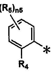
14.前記一般式 (II)において、 Rで表される置換基が下記一般式 (III)で表される 14. In the general formula (II), the substituent represented by R is represented by the following general formula (III)
2 2
ことを特徴とする前記 13に記載の有機エレクト口ルミネッセンス素子。 14. The organic electroluminescent mouth luminescence device as described in 13 above.
[0031] [化 4] 一般式 (ΙΠ) [0031] [Chemical formula 4] General formula (ΙΠ)
[0032] 〔式中、 Rは立体パラメータ値 (Es値)が— 0. 5以下の置換基を表す。 Rは置換基を [In the formula, R represents a substituent having a steric parameter value (Es value) of −0.5 or less. R is a substituent
4 5 表し、 n5は 0〜4の整数を表す。尚、式中 *は結合位置を示す。〕 4 5 and n5 represents an integer of 0 to 4. In the formula, * indicates a bonding position. ]
15.前記一般式(3)が、メシチル基(2, 4, 6 _トリメチルフエニル基)、であることを 特徴とする前記 14に記載の有機エレクト口ルミネッセンス素子。 15. The organic electroluminescent device according to 14, wherein the general formula (3) is a mesityl group (2, 4, 6_trimethylphenyl group).
[0033] 16.前記 1〜: 15のいずれ力、 1項に記載の有機エレクト口ルミネッセンス素子を有す
ることを特徴とする表示装置。 [0033] 16. The organic electoluminescence device of any one of 1 to 15 above: A display device.
[0034] 17.前記 1〜: 15のいずれ力 1項に記載の有機エレクト口ルミネッセンス素子を有す ることを特徴とする照明装置。 [0034] 17. An illuminating device comprising the organic electoluminescence element according to any one of 1 to 15 above.
[0035] 18.前記 17に記載の照明装置と表示手段としての液晶素子を有することを特徴と する表示装置。 [0035] 18. A display device comprising the illumination device according to 17 and a liquid crystal element as display means.
発明の効果 The invention's effect
[0036] 請求の範囲第 1項〜第 4項、及び第 13項〜第 18項に記載の構成によって、低電 圧で駆動する青色燐光発光性有機エレクト口ルミネッセンス素子、及び該素子を用い た表示装置、照明装置を提供することができた。 [0036] According to the configurations of claims 1 to 4 and 13 to 18, a blue phosphorescent organic electoluminescence device driven at a low voltage and the device are used. A display device and a lighting device could be provided.
[0037] また、請求の範囲第 5項〜 12項、及び第 13項〜第 18項に記載の構成により、発光 効率の高い有機エレクト口ルミネッセンス素子、及びそれを用いた照明装置、表示装 置を提供することができた。 [0037] Further, according to the configurations of claims 5 to 12, and 13 to 18, the organic electroluminescent device with high luminous efficiency, and an illumination device and a display device using the same. Could be provided.
図面の簡単な説明 Brief Description of Drawings
[0038] [図 1]本発明の基本的な層構成を示す図である。 FIG. 1 is a diagram showing a basic layer structure of the present invention.
[図 2]有機 EL素子から構成される表示装置の一例を示した模式図である。 FIG. 2 is a schematic view showing an example of a display device composed of organic EL elements.
[図 3]表示部の模式図である。 FIG. 3 is a schematic diagram of a display unit.
[図 4]画素の模式図である。 FIG. 4 is a schematic diagram of a pixel.
[図 5]パッシブマトリクス方式フルカラー表示装置の模式図である。 FIG. 5 is a schematic diagram of a passive matrix type full-color display device.
[図 6]照明装置の概略図である。 FIG. 6 is a schematic view of a lighting device.
[図 7]照明装置の断面図である。 FIG. 7 is a cross-sectional view of the lighting device.
符号の説明 Explanation of symbols
[0039] 1 ディスプレイ [0039] 1 display
3 画素 3 pixels
5 走査線 5 scan lines
6 データ線 6 Data line
7 電源ライン 7 Power line
10 有機 EL素子
12 駆動トランジスタ 10 Organic EL devices 12 Driving transistor
13 コンデンサ 13 Capacitor
A 表示部 A Display section
B 制御部 B Control unit
107 透明電極付きガラス基板 107 Glass substrate with transparent electrode
106 有機 EL層 106 OLED layer
105 陰極 105 cathode
102 ガラスカバー 102 Glass cover
108 窒素ガス 108 nitrogen gas
109 捕水剤 109 Water catcher
発明を実施するための最良の形態 BEST MODE FOR CARRYING OUT THE INVENTION
[0040] 本発明に係る一般式(1)で表される化合物は HOM〇、 LUMO準位が低いため、 正孔の注入はスムーズであると考えられる。そこで、本発明者等は一般式(1)で表さ れる燐光性化合物をドーパントとした素子において、特定の範囲の高い H〇MO、 L UMO準位を有する化合物をホスト化合物として用いると、上記第 1の課題を解決で きることがわかり、請求の範囲第 1項〜第 4項、及び第 13項〜第 18項に記載の発明 に到達した。即ち、発光層においてドーパントに正孔が注入され、ホスト化合物に電 子が注入されることで電荷が発光層中で溜まることなく低電圧化が計れたと考えられ る。 [0040] Since the compound represented by the general formula (1) according to the present invention has low HOM and LUMO levels, it is considered that hole injection is smooth. Therefore, the present inventors have used the phosphor compound represented by the general formula (1) as a dopant, and when a compound having a specific range of high HMO and LUMO levels is used as a host compound, It was found that the first problem could be solved, and the inventions described in claims 1 to 4 and 13 to 18 were reached. In other words, it is considered that the voltage was lowered without charge being accumulated in the light emitting layer by injecting holes into the dopant in the light emitting layer and injecting electrons into the host compound.
[0041] 以下、本発明の各構成要件について詳細に説明する。 [0041] Hereinafter, each component of the present invention will be described in detail.
[0042] まず、本発明に係る H〇MO、 LUMOについて説明する。 [0042] First, HMO and LUMO according to the present invention will be described.
[0043] 本発明において、 H〇MO、 LUMOの値は、米国 Gaussian社製の分子軌道計算 用ソフトウェアである Gaussian98 (Gaussian98、 Revision A. 11. 4, M. J. Fris ch, et al, Gaussian, Inc., Pittsburgh PA, 2002. )を用いて計算した時の値 であり、本発明におけるホスト化合物の HOM〇、 LUMOの値は、キーワードとして B 3LYP/6— 31G *を用いて構造最適化を行うことにより算出した値(eV単位換算値 )と定義し、本発明における燐光性化合物の HOMO、 LUMOの値は、キーワードと して B3LYP/LanL2DZを用いて構造最適化を行うことにより算出した値(eV単位
換算値)と定義する。この計算値が有効な背景には、この手法で求めた計算値と実 験値の相関が高レ、ためである。 [0043] In the present invention, the values of HMO and LUMO are Gaussian98 (Gaussian98, Revision A. 11.4, MJ Frisch, et al, Gaussian, Inc. , Pittsburgh PA, 2002.), and the values of HOM0 and LUMO of the host compound in the present invention should be optimized using B 3LYP / 6- 31G * as a keyword. The HOMO and LUMO values of phosphorescent compounds in the present invention are values calculated by structural optimization using B3LYP / LanL2DZ as keywords (eV unit (Converted value). The reason why this calculated value is effective is that the correlation between the calculated value obtained by this method and the experimental value is high.
[0044] 請求の範囲第 1項〜第 4項及び第 13項〜第 18項の構成に記載の発明において、 "HOMO準位が低レ、 "とは、 HOMO準位の絶対値が小さいことを表し、例えば、ィ匕 合物 Aと化合物 Bの HOMO準位がそれぞれ一 5. 45eV、 - 5. 30eVであるとき、ィ匕 合物 Bの方が化合物 Aよりも H〇M〇準位が低いと言う。また、 "LUMO準位が低い" とは、 LUMO準位の絶対値が小さいことを表し、例えば、化合物 Aと化合物 Bの LU MO準位がそれぞれ— 1. 12eV、 -0. 85eVであるとき、化合物 Bの方が化合物 Aよ りも LUMO準位が低いと言う。 [0044] In the invention described in the constitution of claims 1 to 4 and 13 to 18, "HOMO level is low," means that the absolute value of HOMO level is small. For example, when the HOMO levels of Compound A and Compound B are 5.45 eV and-5.30 eV, respectively, Compound B is HMO level than Compound A. Is low. Also, “LUMO level is low” means that the absolute value of LUMO level is small. For example, when LU MO level of Compound A and Compound B is −1.12eV and −0.85eV, respectively. Compound B has a lower LUMO level than Compound A.
[0045] 本発明の有機 EL素子において、発光層にはホストイ匕合物と燐光性化合物を含有 する。発光層中の主成分であるホストイ匕合物に対する燐光性化合物との混合比は、 好ましくは質量で 0. 1〜 30質量%未満の範囲に調整することである。 In the organic EL device of the present invention, the light emitting layer contains a host compound and a phosphorescent compound. The mixing ratio of the phosphor compound to the host compound as the main component in the light emitting layer is preferably adjusted to a range of 0.1 to less than 30% by mass.
[0046] 次に、請求の範囲第 1項〜第 4項及び第 13項〜第 18項に記載の発明に係る一般 式(1)で表される燐光性化合物について説明する。 Next, the phosphorescent compound represented by the general formula (1) according to the invention described in claims 1 to 4 and 13 to 18 will be described.
[0047] 一般式(1)で表される燐光性化合物は、好ましくは HOMOがー 4· 80〜一 3. 50e V、 LUMOが一 0· 80〜+ 1. OOeVである。 The phosphorescent compound represented by the general formula (1) preferably has a HOMO of −4 · 80 to 1.35 eV and a LUMO of 1 · 80 to + 1.OOeV.
[0048] 一般式(1)で表される燐光性化合物において、 Rで表される置換基としては、例え In the phosphorescent compound represented by the general formula (1), examples of the substituent represented by R include
1 1
ば、アルキル基(例えば、メチノレ基、ェチル基、プロピル基、イソプロピル基、 tert— ブチル基、ペンチル基、へキシル基、ォクチル基、ドデシル基、トリデシノレ基、テトラ デシル基、ペンタデシル基等)、シクロアルキル基(例えば、シクロペンチル基、シクロ へキシル基等)、アルケニル基(例えば、ビニル基、ァリル基等)、アルキニル基(例え ば、ェチニル基、プロパルギル基等)、芳香族炭化水素環基 (芳香族炭素環基、ァリ ール基等ともレ、い、例えば、フエニル基、 p—クロ口フエニル基、メシチル基、トリル基、 キシリル基、ナフチル基、アントリル基、ァズレニル基、ァセナフテュル基、フルォレニ ル基、フヱナントリル基、インデュル基、ピレニル基、ビフヱ二リル基等)、芳香族複素 環基(例えば、ピリジル基、ピリミジニル基、フリル基、ピロリル基、イミダゾリル基、ベン ゾイミダゾリル基、ピラゾリル基、ピラジュル基、トリァゾリル基(例えば、 1, 2, 4—トリア ゾール _ 1—ィル基、 1 , 2, 3 _トリァゾール— 1 _ィル基等)、ォキサゾリル基、ベン
ゾォキサゾリル基、チアゾリル基、イソォキサゾリル基、イソチアゾリル基、フラザニル 基、チェニル基、キノリル基、ベンゾフリル基、ジベンゾフリル基、ベンゾチェ二ル基、 ジベンゾチェニル基、インドリル基、カルバゾリル基、力ノレボリ二ノレ基、ジァザ力ルバ ゾリル基(前記カルボリニル基のカルボリン環を構成する炭素原子の一つが窒素原 子で置き換わったものを示す)、キノキサリニル基、ピリダジニル基、トリアジニル基、 キナゾリニル基、フタラジュル基等)、複素環基 (例えば、ピロリジノレ基、イミダゾリジル 基、モルホリル基、ォキサゾリジノレ基等)、アルコキシ基(例えば、メトキシ基、エトキシ 基、プロピルォキシ基、ペンチルォキシ基、へキシルォキシ基、ォクチルォキシ基、ド デシルォキシ基等)、シクロアルコキシ基(例えば、シクロペンチルォキシ基、シクロへ キシルォキシ基等)、ァリールォキシ基 (例えば、フエノキシ基、ナフチルォキシ基等) 、アルキルチオ基(例えば、メチルチオ基、ェチルチオ基、プロピルチオ基、ペンチル チォ基、へキシルチオ基、ォクチルチオ基、ドデシルチオ基等)、シクロアルキルチオ 基(例えば、シクロペンチルチオ基、シクロへキシルチオ基等)、ァリールチオ基(例え ば、フエ二ルチオ基、ナフチルチオ基等)、アルコキシカルボニル基(例えば、メチル ォキシカルボニル基、ェチルォキシカルボニル基、ブチルォキシカルボニル基、オタ チルォキシカルボニル基、ドデシルォキシカルボニル基等)、ァリールォキシカルボ ニル基(例えば、フエニルォキシカルボニル基、ナフチルォキシカルボニル基等)、ス ルファモイル基(例えば、アミノスルホニル基、メチルアミノスルホニル基、ジメチルアミ ノスルホニル基、ブチルアミノスルホニル基、へキシルアミノスルホニル基、シクロへキ シルアミノスルホニル基、ォクチルアミノスルホニル基、ドデシルアミノスルホニル基、 フエニルアミノスルホニル基、ナフチルアミノスルホニル基、 2—ピリジルアミノスルホニ ル基等)、ァシル基(例えば、ァセチル基、ェチルカルボニル基、プロピルカルボニル 基、ペンチルカルボニル基、シクロへキシルカルボニル基、ォクチルカルボニル基、 2 —ェチルへキシルカルボニル基、ドデシルカルボ二ル基、フヱニルカルボニル基、ナ フチルカルボニル基、ピリジルカルボニル基等)、ァシルォキシ基(例えば、ァセチル ォキシ基、ェチルカルボニルォキシ基、ブチルカルボニルォキシ基、ォクチルカルボ ニルォキシ基、ドデシルカルボニルォキシ基、フエニルカルボニルォキシ基等)、アミ ド基(例えば、メチルカルボニルァミノ基、ェチルカルボニルァミノ基、ジメチルカルボ
ニルァミノ基、プロピルカルボニルァミノ基、ペンチルカルボニルァミノ基、シクロへキ シルカルボニルァミノ基、 2—ェチルへキシルカルボニルァミノ基、ォクチルカルボ二 ノレアミノ基、ドデシルカルボニルァミノ基、フエニルカルボニルァミノ基、ナフチルカル ボニルァミノ基等)、力ルバモイル基(例えば、ァミノカルボニル基、メチルァミノカルボ ニル基、ジメチルァミノカルボニル基、プロピルアミノカルボニル基、ペンチルァミノ力 ルボニル基、シクロへキシルァミノカルボニル基、ォクチルァミノカルボニル基、 2—ェ チルへキシルァミノカルボニル基、ドデシルァミノカルボニル基、フエニルァミノカルボ ニル基、ナフチルァミノカルボニル基、 2 _ピリジルァミノカルボニル基等)、ウレイド基 (例えば、メチノレウレイド基、ェチルウレイド基、ペンチルゥレイド基、シクロへキシルゥ レイド基、ォクチルゥレイド基、ドデシノレウレイド基、フエニルウレイド基、ナフチルウレ イド基、 2_ピリジルアミノウレイド基等)、スルフィエル基(例えば、メチルスルフィエル 基、ェチルスルフィニル基、ブチルスルフィエル基、シクロへキシルスルフィエル基、 2 ェチルへキシルスルフィニル基、ドデシルスルフィエル基、フエニルスルフィエル基 、ナフチルスルフィエル基、 2—ピリジルスルフィエル基等)、アルキルスルホニル基( 例えば、メチルスルホニル基、ェチルスルホニル基、ブチルスルホニル基、シクロへ キシルスルホニル基、 2—ェチルへキシルスルホニル基、ドデシルスルホニル基等)、 ァリールスルホニル基またはへテロアリールスルホニル基(例えば、フエニルスルホニ ル基、ナフチルスルホニル基、 2—ピリジルスルホニル基等)、アミノ基(例えば、ァミノ 基、ェチルアミノ基、ジメチルァミノ基、ブチルァミノ基、シクロペンチルァミノ基、 2— ェチルへキシルァミノ基、ドデシルァミノ基、ァニリノ基、ナフチルァミノ基、 2—ピリジ ルァミノ基等)、シァノ基、ニトロ基、ヒドロキシ基、メルカプト基、シリル基(例えば、トリ メチルシリル基、トリイソプロビルシリル基、トリフエニノレシリノレ基、フエ二ルジェチルシリ ル基等)等が挙げられる。これらの置換基のうち、好ましいものはアルキル基もしくは ァリール基である。 For example, an alkyl group (for example, methinole group, ethyl group, propyl group, isopropyl group, tert-butyl group, pentyl group, hexyl group, octyl group, dodecyl group, tridecinole group, tetradecyl group, pentadecyl group, etc.), cyclo Alkyl groups (eg, cyclopentyl group, cyclohexyl group, etc.), alkenyl groups (eg, vinyl group, allyl group, etc.), alkynyl groups (eg, ethynyl group, propargyl group, etc.), aromatic hydrocarbon ring groups (aromatic For example, a phenyl group, a p-chlorophenyl group, a mesityl group, a tolyl group, a xylyl group, a naphthyl group, an anthryl group, an azulenyl group, an acenaphthyl group, a fluorenyl group. Group, phenanthryl group, indul group, pyrenyl group, biphenylyl group, etc.), aromatic heterocyclic group (for example, pyridyl group) , Pyrimidinyl group, furyl group, pyrrolyl group, imidazolyl group, benzimidazolyl group, pyrazolyl group, pyrazyl group, triazolyl group (for example, 1, 2, 4-triazole _ 1-yl group, 1, 2, 3 _ Triazole-1_yl group, etc.), oxazolyl group, ben Zoxazolyl group, thiazolyl group, isoxazolyl group, isothiazolyl group, furazanyl group, chenyl group, quinolyl group, benzofuryl group, dibenzofuryl group, benzocenyl group, dibenzocenyl group, indolyl group, carbazolyl group, force norbino group, Diaza force rubazolyl group (indicating that one of the carbon atoms constituting the carboline ring of the carbolinyl group is replaced by a nitrogen atom), quinoxalinyl group, pyridazinyl group, triazinyl group, quinazolinyl group, phthaladyl group, etc.), heterocyclic ring Groups (for example, pyrrolidinole group, imidazolidyl group, morpholyl group, oxazolidinole group, etc.), alkoxy groups (for example, methoxy group, ethoxy group, propyloxy group, pentyloxy group, hexyloxy group, octyloxy group, dodecyloxy group, etc.), A cycloalkoxy group (eg, cyclopentyloxy group, cyclohexyloxy group, etc.), aryloxy group (eg, phenoxy group, naphthyloxy group, etc.), alkylthio group (eg, methylthio group, ethylthio group, propylthio group, pentylthio group, Xylthio group, octylthio group, dodecylthio group, etc.), cycloalkylthio group (eg, cyclopentylthio group, cyclohexylthio group, etc.), arylthio group (eg, phenylthio group, naphthylthio group, etc.), alkoxycarbonyl group (eg, A methyloxycarbonyl group, an ethyloxycarbonyl group, a butyloxycarbonyl group, an octyloxycarbonyl group, a dodecyloxycarbonyl group, etc.), an aryloxycarbonyl group (for example, a phenyloxycarbonyl group). Nakhtyroki Cyclocarbonyl group, etc.), sulfamoyl group (for example, aminosulfonyl group, methylaminosulfonyl group, dimethylaminosulfonyl group, butylaminosulfonyl group, hexylaminosulfonyl group, cyclohexylaminosulfonyl group, octylaminosulfonyl group) , Dodecylaminosulfonyl group, phenylaminosulfonyl group, naphthylaminosulfonyl group, 2-pyridylaminosulfonyl group, etc.), acyl group (eg, acetyl group, ethylcarbonyl group, propylcarbonyl group, pentylcarbonyl group, cyclohexyl group) Xylcarbonyl group, octylcarbonyl group, 2-ethylhexylcarbonyl group, dodecylcarbonyl group, phenylcarbonyl group, naphthylcarbonyl group, pyridylcarbonyl group, etc.), acyloxy group (for example, acetyloxy) Group, ethylcarbonyloxy group, butylcarbonyloxy group, octylcarbonyloxy group, dodecylcarbonyloxy group, phenylcarbonyloxy group, etc.), amide group (for example, methylcarbonylamino group, ethylcarbonyloxy group, etc.) Mino group, dimethylcarbo Nylamino group, propylcarbonylamino group, pentylcarbonylamino group, cyclohexylcarbonylamino group, 2-ethylhexylcarbonylamino group, octylcarbonylamino group, dodecylcarbonylamino group, phenylcarbonylamino Group, naphthylcarbonylamino group, etc.), rubamoyl group (for example, aminocarbonyl group, methylaminocarbonyl group, dimethylaminocarbonyl group, propylaminocarbonyl group, pentylaminocarbonyl group, cyclohexylaminocarbonyl group, Octylaminocarbonyl group, 2-ethylhexylaminocarbonyl group, dodecylaminocarbonyl group, phenylaminocarbonyl group, naphthylaminocarbonyl group, 2_pyridylaminocarbonyl group, etc.), ureido group (For example, Mechinoreu Id group, ethylureido group, pentylureido group, cyclohexylureido group, octylureido group, dodecinoureido group, phenylureido group, naphthylureido group, 2_pyridylaminoureido group, etc.), sulfier group (for example, methylsulfier group) Ethylsulfinyl group, butylsulfiel group, cyclohexylsulfiel group, 2-ethylhexylsulfinyl group, dodecylsulfiel group, phenylsulfiel group, naphthylsulfiel group, 2-pyridylsulfiel group, etc.), An alkylsulfonyl group (for example, a methylsulfonyl group, an ethylsulfonyl group, a butylsulfonyl group, a cyclohexylsulfonyl group, a 2-ethylhexylsulfonyl group, a dodecylsulfonyl group), an arylsulfonyl group or a heteroarylsulfuryl group Nyl group (for example, phenylsulfonyl group, naphthylsulfonyl group, 2-pyridylsulfonyl group, etc.), amino group (for example, amino group, ethylamino group, dimethylamino group, butylamino group, cyclopentylamino group, 2-ethylhexylamino group, Dodecylamino group, ananilino group, naphthylamino group, 2-pyridylamino group, etc.), cyano group, nitro group, hydroxy group, mercapto group, silyl group (eg, trimethylsilyl group, triisopropylpropylsilyl group, tripheninoresylinore group) And phenyljetyl silyl group). Of these substituents, preferred are an alkyl group and an aryl group.
Zは 5〜7員環を形成するのに必要な非金属原子群を表す。 Zにより形成される 5〜 7員環としては、例えば、ベンゼン環、ナフタレン環、ピリジン環、ピリミジン環、ピロ一 ル環、チォフェン環、ピラゾール環、イミダゾール環、ォキサゾール環及びチアゾール 環等が挙げられる。これらのうちで好ましいものは、ベンゼン環である。
[0050] B〜Bは炭素原子、窒素原子、酸素原子もしくは硫黄原子を表す。 N (窒素原子)Z represents a nonmetallic atom group necessary for forming a 5- to 7-membered ring. Examples of the 5- to 7-membered ring formed by Z include a benzene ring, naphthalene ring, pyridine ring, pyrimidine ring, pyrrole ring, thiophene ring, pyrazole ring, imidazole ring, oxazole ring, and thiazole ring. . Of these, a benzene ring is preferred. [0050] B to B represent a carbon atom, a nitrogen atom, an oxygen atom or a sulfur atom. N (nitrogen atom)
1 4 14
を含め 5つの原子により形成される含窒素複素環としては単環が好ましい。例えば、 ピロール環、ピラゾール環、イミダゾール環、トリァゾール環、テトラゾール環、ォキサ ゾール環、イソォキサゾール環、チアゾール環、イソチアゾール環、ォキサジァゾール 環及びチアジアゾ一環ル等が挙げられる。これらのうちで好ましいものは、ピラゾーノレ 環、イミダゾール環であり、更に好ましくはイミダゾール環である。これらの環は上記の 置換基によって更に置換されていてもよい。置換基として好ましいものはアルキル基 及びァリール基であり、更に好ましくはァリール基である。 The nitrogen-containing heterocycle formed by 5 atoms including is preferably a monocycle. Examples thereof include a pyrrole ring, a pyrazole ring, an imidazole ring, a triazole ring, a tetrazole ring, an oxazole ring, an isoxazole ring, a thiazole ring, an isothiazole ring, an oxadiazole ring, and a thiadiazo ring. Of these, a pyrazonole ring and an imidazole ring are preferable, and an imidazole ring is more preferable. These rings may be further substituted with the above substituents. Preferred examples of the substituent include an alkyl group and an aryl group, and more preferred is an aryl group.
[0051] Lは X、 Xと共に 2座の配位子を形成する原子群を表す。 X -L -Xで表される 2 [0051] L represents an atomic group forming a bidentate ligand together with X and X. 2 represented by X -L -X
1 1 2 1 1 2 座の配位子の具体例としては、例えば、置換または無置換のフエ二ルビリジン、フエ 二ルビラゾール、フヱニルイミダゾール、フヱニルトリァゾール、フヱニルテトラゾール、 ピラザボール、ピコリン酸及びァセチルアセトン等が挙げられる。これらの基は上記の 置換基によって更に置換されていてもよい。 Specific examples of 1 1 2 1 1 2 bidentate ligands include, for example, substituted or unsubstituted phenylvinylidine, phenylvirazole, phenylimidazole, phenyltriazole, phenyltetrazole, pyrazabol, Examples include picolinic acid and acetylacetone. These groups may be further substituted with the above substituents.
[0052] mlは 1、 2または 3の整数を表し、 m2は 0、 1または 2の整数を表す力 ml +m2は [0052] ml represents an integer of 1, 2 or 3, m2 represents the force of 0, 1 or 2 ml + m2 is
2または 3である。中でも、 m2は 0である場合が好ましい。 Mで表される金属としては 2 or 3. Of these, m2 is preferably 0. As a metal represented by M
1 1
、元素周期表の 8〜: 10族の遷移金属元素(単に遷移金属ともいう)が用いられるが、 中でもイリジウム、白金が好ましぐ更に好ましくはイリジウムである。なお一般式(1) で表される燐光性化合物は、重合性基または反応性基を有していてもいなくてもよい In the periodic table, 8 to 10 group transition metal elements (also simply referred to as transition metals) are used, among which iridium and platinum are preferred, and iridium is more preferred. The phosphorescent compound represented by the general formula (1) may or may not have a polymerizable group or a reactive group.
[0053] また、 B〜Bで形成される含窒素複素環がイミダゾール環が好ましぐイミダゾール [0053] Further, the nitrogen-containing heterocycle formed by B to B is preferably an imidazole ring.
1 4 14
環の場合、前記一般式(1)は前記一般式 (Π)で表されることがより好ましい。 In the case of a ring, the general formula (1) is more preferably represented by the general formula (Π).
[0054] 一般式 (Π)において、 R、 R、 Rは置換基を表す。 Zは 5〜7員環を形成するのに [0054] In the general formula (R), R, R, and R represent a substituent. Z forms a 5- to 7-membered ring
1 2 3 one two Three
必要な非金属原子群を表す。 nlは 0〜5の整数を表す。 Mは元素周期表における 8 Represents the necessary nonmetallic atom group. nl represents an integer of 0 to 5. M is 8 in the periodic table
1 1
族〜 10族の金属を表す。 Xおよび Xは炭素原子、窒素原子もしくは酸素原子を表し Represents Group 10 to Group 10 metals. X and X represent a carbon atom, a nitrogen atom or an oxygen atom
1 2 1 2
、 Lは Xおよび Xとともに 2座の配位子を形成する原子群を表す。 mlは 1、 2または , L represents a group of atoms that together with X and X form a bidentate ligand. ml is 1, 2 or
1 1 2 1 1 2
3の整数を表し、 m2は 0、 1または 2の整数を表す力 ml +m2は 2または 3である。 Represents an integer of 3, m2 represents an integer of 0, 1 or 2 ml + m2 is 2 or 3.
[0055] 一般式 (Π)において、 R、 R、 Rで表される置換基は前記一般式(1)における Rで In the general formula (式), the substituents represented by R, R, and R are the same as R in the general formula (1).
1 2 3 1 表される置換基と同義である。また、 Z、 M、 Xおよび X、 L等についても前
記一般式(1)におけるものと同義である。また、 ml、 m2も同義である。 1 2 3 1 Synonymous with the substituent represented. Also for Z, M, X and X, L etc. It has the same meaning as in the general formula (1). Moreover, ml and m2 are also synonymous.
[0056] また、一般式 (Π)の Rで表される基として、芳香族炭化水素環基 (芳香族炭素環基 [0056] In addition, as the group represented by R in the general formula (Π), an aromatic hydrocarbon ring group (aromatic carbocyclic group)
2 2
)が好ましぐなかでも置換ァリール基が好ましぐ置換ァリールとして下記一般式 (III The preferred general formula (III) is a substituted aryl group in which a substituted aryl group is preferred.
)で表される基が好ましい。 ) Is preferred.
[0057] [化 5] 一般式 (ΙΠ)
[0057] [Chemical 5] General formula (ΙΠ)
[0058] 一般式 (ΠΙ)において、 Rは、立体パラメータ値 (Es値)が— 0. 5以下の置換基を表 [0058] In the general formula (ΠΙ), R represents a substituent having a steric parameter value (Es value) of −0.5 or less.
4 Four
す。 Rは Rと同じで、 n5は 0〜4の整数を表す。尚、 *は結合位置を表す。 The R is the same as R, and n5 represents an integer of 0-4. Note that * represents a binding position.
5 1 5 1
[0059] ここで、 Es値とは化学反応性より誘導された立体パラメータであり、この値が小さけ れば小さいほど立体的に嵩高い置換基ということができる。 Here, the Es value is a steric parameter derived from chemical reactivity, and the smaller this value, the more sterically bulky a substituent can be said.
[0060] 以下、 Es値について説明する。一般に、酸性条件下でのエステルの加水分解反応 におレ、ては、置換基が反応の進行に対して及ぼす影響は立体障害だけと考えてよ いことが知られており、この事を利用して置換基の立体障害を数値化したものが Es値 である。 Hereinafter, the Es value will be described. In general, it is known that the influence of substituents on the progress of a reaction may be considered only as steric hindrance in the hydrolysis reaction of an ester under acidic conditions. The Es value is the numerical value of the steric hindrance of the substituent.
[0061] 例えば置換基 Xの Es値は、次の化学反応式 [0061] For example, the Es value of the substituent X is represented by the following chemical reaction formula:
X-CH COOR +H〇→X— CH COOH + R OH X-CH COOR + H ○ → X— CH COOH + R OH
2 X 2 2 X 2 X 2 2 X
で表される、酢酸のメチル基の水素原子 1つを置換基 Xで置換した α位モノ置換酢 酸から誘導される α位モノ置換酢酸エステルを酸性条件下で加水分解する際の反 応速度定数 kXと、次の化学反応式 Reaction rate when hydrolyzing α -monosubstituted acetic acid ester derived from α -monosubstituted acetic acid in which one hydrogen atom of the methyl group of acetic acid is substituted with substituent X Constant kX and the following chemical reaction formula
CH COOR +H 0→CH COOH + R OH CH COOR + H 0 → CH COOH + R OH
3 Y 2 3 Υ 3 Y 2 3 Υ
(Rは Rと同じである)で表される、上記のひ位モノ置換酢酸エステルに対応する酢 (R is the same as R) Vinegar corresponding to the above mono-substituted acetate ester
X Υ X Υ
酸エステルを酸性条件下で加水分解する際の反応速度定数 kHから次の式で求めら れる。 From the reaction rate constant kH when the acid ester is hydrolyzed under acidic conditions, the following formula is obtained.
[0062] Es =log (kX/kH)
置換基 Xの立体障害により反応速度は低下し、その結果 kXく kHとなるので Es値 は通常負となる。実際に Es値を求める場合には、上記の二つの反応速度定数 kXと k Hを求め、上記の式により算出する。 [0062] Es = log (kX / kH) The reaction rate decreases due to the steric hindrance of the substituent X, resulting in kX and kH, so the Es value is usually negative. When the Es value is actually obtained, the above two reaction rate constants kX and kH are obtained and calculated by the above formula.
[0063] Es値の具体的な例は、 Unger, S. H., Hansch, C. , Prog. Phys. Org. Che m. , 12, 91 (1976)に詳しく記載されている。また、『薬物の構造活性相関』 (化学 の領域増干 IJ 122号、南江堂)、「American Chemical Society Professional Reference Book, ' Exploring QSAR' p. 81 Table 3— 3」にも、その具体的 な数値の記載がある。次にその一部を表 1に示す。 [0063] Specific examples of Es values are described in detail in Unger, S. H., Hansch, C., Prog. Phys. Org. Chem., 12, 91 (1976). The specific values are also shown in “Structure-activity relationship of drugs” (Ishi 122, Nankodo), “American Chemical Society Professional Reference Book, 'Exploring QSAR' p. 81 Table 3-3”. Is described. Some of these are shown in Table 1.
[0064] [表 1] [0064] [Table 1]
[0065] ここで、注意するのは本明細書で定義するところの Es値は、メチル基のそれを 0とし て定義したのではなぐ水素原子を 0としたものであり、メチル基を 0とした Es値から 1 . 24を差し引いたものである。
[0066] 本発明において Rは、立体パラメータ値 (Es値)がー 0· 5以下の置換基を表す。 [0065] Here, it should be noted that the Es value as defined in the present specification is that a hydrogen atom that is not defined as that of a methyl group is 0, and that the methyl group is 0. This is the Es value minus 1.24. In the present invention, R represents a substituent having a steric parameter value (Es value) of −0.5.
4 Four
好ましくは 7. 0以上 0. 6以下であり、最も好ましくは 7. 0以上 1. 0以下であ る。 It is preferably 7.0 or more and 0.6 or less, and most preferably 7.0 or more and 1.0 or less.
[0067] また、本発明においては、 Rに、例えば、ケト—エノール互変異性体が存在し得る [0067] In the present invention, for example, a keto-enol tautomer may exist in R.
4 Four
場合、ケト部分はェノールの異性体として Es値を換算している。他の互変異性が存 在する場合も同様の換算方法にぉレ、て Es値を換算する。 In this case, the keto moiety is converted to Es value as an isomer of enol. If other tautomers exist, the Es value is converted using the same conversion method.
[0068] 以下に本発明の一般式(1)、また一般式 (II)で表されるリン光発光性化合物の具 体的な例を挙げるが、本発明はこれらに限定されるものではない。 [0068] Specific examples of the phosphorescent compound represented by the general formula (1) and the general formula (II) of the present invention are given below, but the present invention is not limited thereto. .
[0069] [化 6]
[0069] [Chemical 6]
[OZOO] [OZOO]
l6 S0/L00ZdT/13d
[6^>] [ 00] l6 S0 / L00ZdT / 13d [6 ^>] [00]
T6l7S0/.00Zdf/X3d OS Ζ9£80動 OAV
T6l7S0 / .00Zdf / X3d OS Ζ9 £ 80 OAV
[0074] [化 11]
[0074] [Chemical 11]
[0075] [化 12]
[0075] [Chemical 12]
[0076] [化 13]
[0076] [Chemical 13]
[0077] [化 14]
[0077] [Chemical 14]
[0078] [化 15]
[0078] [Chemical 15]
[0079] [化 16]
[0079] [Chemical 16]
[0080] [化 17]
[0080] [Chemical 17]
[0081] [化 18]
[0081] [Chemical 18]
[6I^]>] [Z800] [6I ^]>] [Z800]
[0083] [化 20]
IZ^ [ 800] [0083] [Chemical 20] IZ ^ [800]
これらの金属錯体は、例えば、 Organic Letter誌 vol3 No. 16 2579〜258 1頁(2001)、 Inorganic Chemistry 第 30卷 第 8号 1685〜1687頁(1991年 )、J. Am. Chem. Soc. 123卷 4304頁(2001年)、 Inorganic Chemistry 第 40卷 第 7号 1704〜1711頁(2001年)、 Inorganic Chemistry 第 41卷 第 12号 3055〜3066頁(2002年)、 New Journal of Chemistry 第 26卷 1
171頁(2002年)、 European Journal of Organic Chemistry 第 4卷 695 〜709頁(2004年)、更にこれらの文献中に記載の参考文献等の方法を適用するこ とにより合成できる。 These metal complexes are described in, for example, Organic Letter vol3 No. 16 2579-258 1 (2001), Inorganic Chemistry No. 30 No. 8, 1685-1687 (1991), J. Am. Chem. Soc. 123卷 4304 (2001), Inorganic Chemistry No. 40 No. 7 1704-1711 (2001), Inorganic Chemistry No. 41 No. 12 3055-3066 (2002), New Journal of Chemistry No. 26 1 171 (2002), European Journal of Organic Chemistry pp. Pp. 695-709 (2004), and further by applying methods such as references described in these documents.
[0086] 次に、請求の範囲第 1項〜第 4項及び第 13項〜第 18項に係わる発明のホスト化合 物について説明する。 [0086] Next, the host compound of the invention according to claims 1 to 4 and 13 to 18 will be described.
[0087] 請求の範囲第 1項〜第 4項及び第 13項〜第 18項に係わる発明に用いられるホスト 化合物は、 HOMO準位が—7. 20〜― 5. 42eV、 LUMO準位が—2. 30〜― 0. 5 [0087] The host compounds used in the inventions according to claims 1 to 4 and 13 to 18 have a HOMO level of −7.20 to 5.42 eV and a LUMO level of − 2.30〜― 0.5
OeVであり、発光層に含有される化合物のうちで室温(25°C)において燐光発光の燐 光量子収率が、 0. 01未満の化合物である。 Among the compounds contained in the light emitting layer, OeV is a compound having a phosphorescence quantum yield of phosphorescence of less than 0.01 at room temperature (25 ° C.).
[0088] 請求の範囲第 1項〜第 4項及び第 13項〜第 18項に係わる発明に用いられるホスト 化合物としては、併用される燐光性化合物の燐光 0— 0バンドよりも短波長なそれをも つ化合物が好ましぐ燐光性化合物にその燐光 0— 0バンドが 470nm以下である青 色の発光成分を含む化合物を用いる場合には、ホストイ匕合物としては燐光 0— 0バン ドが 460nm以下であることが好ましい。 [0088] As the host compound used in the invention according to claims 1 to 4 and 13 to 18, the phosphor compound used in combination has a wavelength shorter than the phosphorescence 0-0 band. When a compound containing a blue light-emitting component whose phosphorescence 0-0 band is 470 nm or less is used as the phosphorescent compound preferred by the compound having a phosphorescence, the phosphorescence 0-0 band is used as the host compound. It is preferable that it is 460 nm or less.
[0089] 本発明における燐光の 0— 0バンドの測定方法について説明する。まず、燐光スぺ タトルの測定方法にっレ、て説明する。 A method for measuring the 0-0 band of phosphorescence in the present invention will be described. First, the method for measuring the phosphorescence spectrum will be explained.
[0090] 測定するホストイ匕合物をよく脱酸素されたエタノール/メタノール =4/1 (vol/vol )の混合溶媒に溶かし、燐光測定用セルに入れた後液体窒素温度 77° Kで励起光 を照射し、励起光照射後 100msでの発光スペクトルを測定する。燐光は蛍光に比べ 発光寿命が長いため、 100ms後に残存する光はほぼ燐光であると考えることができ る。なお、燐光寿命が 100msより短い化合物に対しては遅延時間を短くして測定し ても構わないが、蛍光と区別できなくなるほど遅延時間を短くしてしまうと、燐光と蛍 光が分離できないので問題となるため、その分離が可能な遅延時間を選択する必要 力 Sある。 [0090] The host compound to be measured was dissolved in a well-deoxygenated ethanol / methanol = 4/1 (vol / vol) mixed solvent, placed in a phosphorescence measurement cell, and then excited at a liquid nitrogen temperature of 77 ° K. , And measure the emission spectrum at 100 ms after excitation light irradiation. Since phosphorescence has a longer emission lifetime than fluorescence, it can be considered that the light remaining after 100 ms is almost phosphorescent. For compounds with a phosphorescence lifetime shorter than 100 ms, measurement may be performed with a shorter delay time. However, if the delay time is shortened so that it cannot be distinguished from fluorescence, phosphorescence and fluorescence cannot be separated. Since this becomes a problem, there is a need to select a delay time that can be separated.
[0091] また、上記溶剤系で溶解できない化合物については、その化合物を溶解しうる任意 の溶剤を使用してもよい (実質上、上記測定法では燐光波長の溶媒効果はごくわず かなので問題ない)。 [0091] For the compound that cannot be dissolved in the solvent system, any solvent that can dissolve the compound may be used (substantially no problem is caused by the solvent effect of the phosphorescence wavelength in the measurement method described above). ).
[0092] 次に 0_0バンドの求め方である力 本発明においては、上記測定法で得られた燐
光スペクトルチャートの中で最も短波長側に現れる発光極大波長をもって 0— 0バン ドと定義する。 [0092] Next, force, which is a method for obtaining the 0_0 band, in the present invention, phosphorus obtained by the above-described measurement method is used. The maximum emission wavelength that appears on the shortest wavelength side in the optical spectrum chart is defined as 0-0 band.
[0093] 燐光スペクトルは通常強度が弱いことが多いため、拡大するとノイズとピークの判別 が難しくなるケースがある。このような場合には励起光照射直後の発光スペクトル (便 宜上これを定常光スペクトルと言う)を拡大し、励起光照射後 100ms後の発光スぺク トル (便宜上これを燐光スペクトルと言う)と重ね合わせ、燐光スペクトルに由来する定 常光スペクトル部分からピーク波長を読みとることで決定することができる。また、燐 光スペクトルをスムージング処理することでノイズとピークを分離し、ピーク波長を読み とることもできる。なお、スムージング処理としては、 Savitzky&Golayの平滑化法等 を適用すること力 Sできる。 [0093] Since the phosphorescence spectrum is usually weak in intensity, it may be difficult to distinguish between noise and peak when enlarged. In such a case, the emission spectrum immediately after the excitation light irradiation (for convenience, this is called the steady light spectrum) is expanded, and the emission spectrum 100 ms after the excitation light irradiation (for convenience, this is called the phosphorescence spectrum). And the peak wavelength is read from the portion of the constant light spectrum derived from the phosphorescence spectrum. In addition, by smoothing the phosphor spectrum, noise and peak can be separated and peak wavelength can be read. As smoothing processing, the Savitzky & Golay smoothing method can be applied.
[0094] 請求の範囲第 1項〜第 4項及び第 13項〜第 18項に記載の発明に用いられるホス ト化合物は構造的には特に制限はなぐ低分子化合物でも繰り返し単位をもつ高分 子化合物でもよぐビニル基やエポキシ基のような重合性基を有する低分子化合物( 蒸着重合性ホスト化合物)でもいい。正孔輸送能、電子輸送能を有しつつ、且つ発 光の長波長化を防ぎ、なお且つ高 Tg (ガラス転移温度)である化合物が好ましレ、。 [0094] The host compound used in the invention described in claims 1 to 4 and 13 to 18 is not particularly limited in terms of structure, but is a low molecular weight compound having a repeating unit. It may be a low molecular weight compound (deposited polymerizable host compound) having a polymerizable group such as a vinyl group or an epoxy group. Preference is given to compounds that have hole transporting and electron transporting capabilities, prevent emission of longer wavelengths, and have a high Tg (glass transition temperature).
[0095] 請求の範囲第 1項〜第 4項、及び第 13項〜第 18項に記載の発明におけるホスト化 合物は、代表的には力ルバゾール誘導体、トリアリールァミン誘導体、芳香族ボラン 誘導体、含窒素複素環化合物、チォフェン誘導体、フラン誘導体、オリゴァリーレン 化合物等の基本骨格を有するもの、またはカルボリン誘導体ゃ該カルボリン誘導体 のカルボリン環を構成する炭化水素環の炭素原子の少なくとも一つが窒素原子で置 換されている環構造を有する誘導体等が挙げられる。 [0095] The host compounds in the inventions of claims 1 to 4 and 13 to 18 are typically rubazole derivatives, triarylamine derivatives, aromatic boranes. A derivative, a nitrogen-containing heterocyclic compound, a thiophene derivative, a furan derivative, an oligoarylene compound or the like having a basic skeleton, or a carboline derivative, wherein at least one carbon atom of the hydrocarbon ring constituting the carboline ring of the carboline derivative is nitrogen Examples thereof include derivatives having a ring structure substituted with an atom.
[0096] 請求の範囲第 1項〜第 4項、及び第 13項〜第 18項に係わるホスト化合物として具 体的には、下記一般式(2)で表される化合物が好ましい。 [0096] Specifically, the host compound according to claims 1 to 4 and 13 to 18 is preferably a compound represented by the following general formula (2).
[0097] [化 22] [0097] [Chemical 22]
[0098] 一般式(2)におレ、て、 Ar及び Arは各々芳香族炭化水素基または芳香族複素環 [0098] In general formula (2), Ar and Ar are each an aromatic hydrocarbon group or an aromatic heterocyclic ring.
1 2 1 2
基を表す。 Ar及び Arで表される芳香族炭化水素基 (芳香族炭素環基、ァリール基 Represents a group. Ar and an aromatic hydrocarbon group represented by Ar (aromatic carbocyclic group, aryl group)
1 2 1 2
等ともいう)としては、例えば、フエニル基、 p クロ口フエ二ル基、メシチル基、トリル基 、キシリル基、ナフチル基、アントリル基、ァズレニル基、ァセナフテュル基、フルォレ ニル基、フヱナントリル基、インデュル基、ピレニル基、ビフヱ二リル基等が挙げられる Examples thereof include phenyl group, p-chlorophenyl group, mesityl group, tolyl group, xylyl group, naphthyl group, anthryl group, azulenyl group, acenaphthyl group, fluorenyl group, phenanthryl group, indur group. , Pyrenyl group, biphenyl benzylyl group, etc.
。 Ar及び Arで表される芳香族複素環基としては、例えば、ピリジノレ基、ピリミジニノレ. Examples of the aromatic heterocyclic group represented by Ar and Ar include a pyridinole group and a pyrimidininole group.
1 2 1 2
基、フリル基、ピロリル基、イミダゾリル基、ベンゾイミダゾリル基、ピラゾリル基、ピラジ 二ノレ基、トリアソ^リノレ基(ί列免 ίま'、 1, 2, 4 _卜リアソ^ーノレ一 1—イノレ基、 1 , 2, 3 _トリァ ゾール _ 1 _ィル基等)、ォキサゾリル基、ベンゾォキサゾリル基、チアゾリル基、イソ ォキサゾリル基、イソチアゾリル基、フラザニル基、チェニル基、キノリ Group, furyl group, pyrrolyl group, imidazolyl group, benzimidazolyl group, pyrazolyl group, pyrazinole group, triazol linole group (ί column free, 1, 2, 4 _ ria triol 1-inole group, 1, 2, 3_triazole_1_yl group, etc.), oxazolyl group, benzoxazolyl group, thiazolyl group, isoxazolyl group, isothiazolyl group, furazanyl group, chenyl group, quinolyl
ル基、ベンゾフリル基、ジベンゾフリル基、ベンゾチェ二ル基、ジベンゾチェニル基、 インドリル基、カルバゾリル基、力ノレボリ二ノレ基、ジァザカルバゾリル基(前記カルボリ ニル基のカルボリン環を構成する炭素原子の一つが窒素原子で置き換わったものを 示す)、キノキサリニル基、ピリダジニル基、トリアジニル基、キナゾリニル基、フタラジ ニル基等が挙げられる。 Group, benzofuryl group, dibenzofuryl group, benzocenyl group, dibenzocenyl group, indolyl group, carbazolyl group, force norbinolinole group, diazacarbazolyl group (which constitutes the carboline ring of the above carbolinyl group) A carbon atom is replaced by a nitrogen atom), a quinoxalinyl group, a pyridazinyl group, a triazinyl group, a quinazolinyl group, a phthalazinyl group, and the like.
[0099] なお、これらの基は各々置換基を有していてもよぐ該置換基としては、アルキル基 [0099] These groups may each have a substituent. Examples of the substituent include an alkyl group.
(例えば、メチル基、ェチル基、プロピル基、イソプロピル基、 t ブチル基等)、シクロ アルキル基(例えば、シクロペンチル基、シクロへキシル基等)、アルケニル基(例え ば、ビュル基、ァリル基等)、アルキニル基 (例えば、ェチニル基等)、芳香族炭化水 素基(芳香族炭素環基、ァリール基等ともいい、例えば、フエニル基、 2, 6 ジメチノレ フエニル基等)、芳香族複素環基 (ヘテロァリール基ともいい、例えば、フリル基、チェ ニル基、ピリジル基、ピリダジル基、ピリミジル基、ピラジル基、トリアジル基、イミダゾリ ル基、ピラゾリル基、チアゾリル基、キナゾリル基、フタラジノレ基等)、複素環基(ヘテロ 環基ともいい、例えば、ピロリジル基、イミダゾリジル基、モルホリル基、ォキサゾリジル 基等)、アルコキシ基 (例えば、メトキシ基、エトキシ基等)、シクロアルコキシ基 (例え ば、シクロペンチルォキシ基、シクロへキシルォキシ基等)、ァリールォキシ基(例え ば、フエノキシ基、ナフチルォキシ基等)、アルキルチオ基 (例えば、メチルチオ基、ェ チルチオ基等)、シクロアルキルチオ基(例えば、シクロペンチルチオ基、シクロへキ
シノレチォ基等)、ァリールチオ基 (例えば、フエ二ルチオ基、ナフチルチオ基等)、ァ ノレコキシカルボニル基(例えば、メチルォキシカルボニル基、ェチルォキシカルボ二 ル基等)、ァリールォキシカルボニル基(例えば、フエニルォキシカルボニル基、ナフ チルォキシカルボニル基等)、スルファモイル基(例えば、アミノスルホニル基、メチル アミノスルホニル基、ジメチルアミノスルホニル基等)、ァシル基(例えば、ァセチル基 、ェチルカルボニル基等)、ァシルォキシ基(例えば、ァセチルォキシ基、ェチルカル ボニルォキシ基等)、アミド基(例えば、メチルカルボニルァミノ基、ェチルカルボニル アミノ基、ジメチルカルボニルァミノ基等)、力ルバモイル基(例えば、ァミノカルボニル 基、メチルァミノカルボニル基、ジメチルァミノカルボニル基等)、ウレイド基(例えば、 メチルウレイド基、ェチルウレイド基等)、アミノ基 (例えば、アミノ基、ェチルァミノ基、 ジメチルァミノ基、ジフヱニルァミノ基等)、ハロゲン原子 (例えば、フッ素原子、塩素 原子、臭素原子等)、フッ化炭化水素基 (例えば、フルォロメチル基、トリフルォロメチ ル基等)、シァノ基、ニトロ基、ヒドロキシ基、メルカプト基、シリル基(例えば、トリメチル シリル基等)等が挙げられる。 (For example, methyl group, ethyl group, propyl group, isopropyl group, t-butyl group, etc.), cycloalkyl group (for example, cyclopentyl group, cyclohexyl group, etc.), alkenyl group (for example, bur group, aryl group, etc.) , Alkynyl groups (for example, ethynyl groups), aromatic hydrocarbon groups (also called aromatic carbocyclic groups, aryl groups, etc., for example, phenyl groups, 2,6 dimethylenophenyl groups, etc.), aromatic heterocyclic groups ( Also referred to as a heteroaryl group, for example, furyl group, phenyl group, pyridyl group, pyridazyl group, pyrimidyl group, pyrazyl group, triazyl group, imidazolyl group, pyrazolyl group, thiazolyl group, quinazolyl group, phthalazinole group, etc.), heterocyclic group (Also referred to as heterocyclic group, for example, pyrrolidyl group, imidazolidyl group, morpholyl group, oxazolidyl group, etc.), alkoxy group (Eg, methoxy group, ethoxy group, etc.), cycloalkoxy group (eg, cyclopentyloxy group, cyclohexyloxy group, etc.), aryloxy group (eg, phenoxy group, naphthyloxy group, etc.), alkylthio group (eg, methylthio group) Group, ethylthio group, etc.), cycloalkylthio group (for example, cyclopentylthio group, cyclohexyl group). Synolethio group, etc.), arylthio group (eg, phenylthio group, naphthylthio group, etc.), aralkoxycarbonyl group (eg, methyloxycarbonyl group, ethyloxycarbonyl group, etc.), aryloxy A carbonyl group (for example, phenyloxycarbonyl group, naphthyloxycarbonyl group, etc.), a sulfamoyl group (for example, aminosulfonyl group, methylaminosulfonyl group, dimethylaminosulfonyl group, etc.), an acyl group (for example, acetyl group, Ethylcarbonyl group, etc.), acyloxy group (for example, acetyloxy group, ethylcarbonyloxy group, etc.), amide group (for example, methylcarbonylamino group, ethylcarbonylamino group, dimethylcarbonylamino group, etc.), rubamoyl group ( For example, an aminocarbonyl group, methylaminocarbonyl Group, dimethylaminocarbonyl group, etc.), ureido group (eg, methylureido group, ethylureido group, etc.), amino group (eg, amino group, ethylamino group, dimethylamino group, diphenylamino group, etc.), halogen atom (eg, fluorine atom) , Chlorine atom, bromine atom, etc.), fluorinated hydrocarbon group (eg, fluoromethyl group, trifluoromethyl group, etc.), cyano group, nitro group, hydroxy group, mercapto group, silyl group (eg, trimethylsilyl group, etc.), etc. Can be mentioned.
[0100] また Arと Arで置換された窒素原子は、更に Arと Arの窒素原子が置換した位置 [0100] Further, the nitrogen atom substituted with Ar and Ar is a position where the nitrogen atom of Ar and Ar is further substituted.
1 2 1 2 1 2 1 2
の隣接位と窒素原子の間で環を形成してもよぐ具体的には下記のような構造をとつ てもよい。 A ring may be formed between the adjacent position of and a nitrogen atom. Specifically, the following structure may be adopted.
[0101] [化 23] [0101] [Chemical 23]
[0102] Raは水素原子、アルキル基、シクロアルキル基、芳香族炭化水素基、芳香族複素 [0102] Ra is a hydrogen atom, an alkyl group, a cycloalkyl group, an aromatic hydrocarbon group, an aromatic complex
1 1
環基または複素環基を表し、置換基を有してレ、てもよレ、。 Represents a cyclic group or a heterocyclic group and has a substituent.
[0103] Raで表されるアルキル基としては、例えば、メチル基、ェチル基、プロピル基、イソ
プロピル基、ブチル基、イソブチル基、 sec—ブチル基、 tert—ブチル基、ペンチノレ 基、イソペンチル基、ネオペンチル基、 tert—ペンチル基、へキシル基、イソへキシ ル基、ォクチル基、ドデシル基、トリデシル基、テトラデシル基、ペンタデシノレ基、 2— ェチル一へキシル基、ゥンデシノレ基、テトラデシノレ基等が挙げられる。 Raで表される [0103] Examples of the alkyl group represented by Ra include a methyl group, an ethyl group, a propyl group, and an iso group. Propyl group, butyl group, isobutyl group, sec-butyl group, tert-butyl group, pentynole group, isopentyl group, neopentyl group, tert-pentyl group, hexyl group, isohexyl group, octyl group, dodecyl group, tridecyl Group, tetradecyl group, pentadecinole group, 2-ethyl hexyl group, undecinole group, tetradecinole group and the like. Represented by Ra
1 シクロアルキル基としては、例えば、シクロペンチル基、シクロへキシル基等が挙げら れる。 Raで表される芳香族炭化水素基、及び芳香族複素環基としては、例えば、上 Examples of 1 cycloalkyl group include a cyclopentyl group and a cyclohexyl group. Examples of the aromatic hydrocarbon group and aromatic heterocyclic group represented by Ra include the above
1 1
述の Arと Arの説明で挙げた芳香族炭化水素基等及び芳香族複素環基等が挙げ Aromatic hydrocarbon groups and aromatic heterocyclic groups mentioned in the description of Ar and Ar
1 2 1 2
られる。 Raで表される複素環基としては、例えば、ピロリジノレ基、イミダゾリジノレ基、モ It is done. Examples of the heterocyclic group represented by Ra include pyrrolidinole group, imidazolidinole group, and
1 1
ルホリル基、ォキサゾリジノレ基等が挙げられる。なお、これらの基は各々置換基を有 していてもよぐ該置換基としては上述の Ar及び Arの置換基の例として挙げたもの A ruphoryl group, an oxazolidinole group, etc. are mentioned. Each of these groups may have a substituent. Examples of the substituent include those mentioned above as examples of Ar and Ar substituents.
1 2 1 2
と同様のものが挙げられる。 The same thing is mentioned.
[0104] 一般式(2)で表される化合物のうち、一般式(3)〜一般式(7)で表される化合物が 更に好ましい。 [0104] Of the compounds represented by the general formula (2), compounds represented by the general formula (3) to the general formula (7) are more preferable.
[0105] [化 24] [0105] [Chemical 24]
[0106] 一般式(3)におレ、て、 Ar〜Arは芳香族炭化水素基または芳香族複素環基を表 [0106] In general formula (3), Ar to Ar represent an aromatic hydrocarbon group or an aromatic heterocyclic group.
1 4 14
し、置換基を有していてもよい。 Ar〜Arで表される基としては、具体的には一般式 ( And may have a substituent. Specific examples of the group represented by Ar to Ar include a general formula (
1 4 14
2)における Ar及び Arと同様のもの力 S挙げられる。また、 Arと Arで置換された窒 The same force S as Ar and Ar in 2). Ar and Ar substituted nitrogen
1 2 1 2 1 2 1 2
素原子または Arと Arで置換された窒素原子は、一般式(2)における Ar及び Arと Elementary atoms or nitrogen atoms substituted with Ar and Ar are the same as Ar and Ar in general formula (2).
3 4 1 2 同様に、更に Ar及び Arの窒素原子、または Arと Arの窒素原子が置換した位置 3 4 1 2 Similarly, positions where Ar and Ar nitrogen atoms or Ar and Ar nitrogen atoms are substituted
1 2 3 4 1 2 3 4
の隣接位と窒素原子の間で環を形成してもよい。 A ring may be formed between the adjacent position of and a nitrogen atom.
[0107] Arは 2価のァリーレン基またはへテロアリーレン基を表し、置換基を有していてもよ [0107] Ar represents a divalent arylene group or a heteroarylene group, and may have a substituent.
5 Five
レ、。 Arで表されるァリーレン基またはへテロアリーレン基としては、例えば、 1 , 3—フ Les. As the arylene group or heteroarylene group represented by Ar, for example, 1, 3-fluoro
5 Five
ヱ二レン、 1, 4—フヱニレン、 1, 5—ナフチレン、ピリジン一 2, 5—ジィル等が挙げら
れる。 Lは 2価の連結基を表し、 nlは 0〜6の整数を表し、複数の Lは各々異なってい ても同一でもよい。 ヱ ylene, 1,4-funylene, 1,5-naphthylene, pyridine 2,5-diyl, etc. It is. L represents a divalent linking group, nl represents an integer of 0 to 6, and a plurality of L may be different or the same.
[0108] [化 25] [0108] [Chemical 25]
[0109] 一般式(4)におレ、て、 R、 Rは置換基を表し、 nl及び n2は 0〜4を表す。 Ar〜Ar [0109] In general formula (4), R and R each represent a substituent, and nl and n2 each represent 0 to 4. Ar to Ar
1 2 1 4 は芳香族炭化水素基または芳香族複素環基を表し、置換基を有していてもよい。 Ar 〜Arで表される基としては、具体的には一般式(2)における Ar及び Arと同様のも 1 2 1 4 represents an aromatic hydrocarbon group or an aromatic heterocyclic group, and may have a substituent. Specifically, the groups represented by Ar to Ar are the same as those of Ar and Ar in the general formula (2).
1 4 1 2 のが挙げられる。 1 4 1 2
[0110] Raは水素原子、アルキル基、シクロアルキル基、芳香族炭化水素基、芳香族複素 [0110] Ra is a hydrogen atom, an alkyl group, a cycloalkyl group, an aromatic hydrocarbon group, an aromatic complex
1 1
環基または複素環基を表し、更に置換基を有していてもよい。また、 Arと Arで置換 Represents a cyclic group or a heterocyclic group, and may further have a substituent. Also replace with Ar and Ar
1 2 された窒素原子または Arと Arで置換された窒素原子は、一般式(2)における Ar 1 2 or a nitrogen atom substituted with Ar and Ar represents Ar in general formula (2)
3 4 1 及び Arと同様に、更に Ar及び Arの窒素原子、または Arと Arの窒素原子が置換 3 4 As in 1 and Ar, Ar and Ar nitrogen atoms, or Ar and Ar nitrogen atoms are further substituted.
2 1 2 3 4 2 1 2 3 4
した位置の隣接位と窒素原子の間で環を形成してもよい。 A ring may be formed between the adjacent position and the nitrogen atom.
[0111] [化 26] [0111] [Chemical 26]
—艫靖 — 艫 靖
[0112] 一般式(5)において、 Raは水素原子、アルキル基、シクロアルキル基、芳香族炭 [0112] In the general formula (5), Ra represents a hydrogen atom, an alkyl group, a cycloalkyl group, an aromatic carbon
1 1
化水素基、芳香族複素環基または複素環基を表し、更に一般式(2)において上記 A r及び Arが有してもよい置換基で置換されていてもよい。 R、 Rは各々置換基を表 Represents a hydrogen fluoride group, an aromatic heterocyclic group or a heterocyclic group, and may be further substituted with a substituent which Ar and Ar may have in the general formula (2). R and R each represents a substituent.
1 2 1 2 1 2 1 2
し、 nl、 n2は 0〜4を表す。 Nl and n2 represent 0-4.
[0113] [化 27] [0113] [Chemical 27]
―翁 ― 翁
[0114] 一般式(6)において、 Raは水素原子、アルキル基、シクロアルキル基、芳香族炭 [0114] In the general formula (6), Ra represents a hydrogen atom, an alkyl group, a cycloalkyl group, an aromatic carbon.
1 1
化水素基、芳香族複素環基または複素環基を表し、更に一般式(2)において上記 A r及び Arが有してもよい置換基で置換されていてもよい。 R、 Rは各々置換基を表 Represents a hydrogen fluoride group, an aromatic heterocyclic group or a heterocyclic group, and may be further substituted with a substituent which Ar and Ar may have in the general formula (2). R and R each represents a substituent.
1 2 1 2 1 2 1 2
し、 nlは 0〜4を表し、 n2は 0〜3を表す。 Nl represents 0 to 4, and n2 represents 0 to 3.
[0115] [化 28] [0115] [Chemical 28]
[0116] 一般式(7)において、 Raは水素原子、アルキル基、シクロアルキル基、芳香族炭 [0116] In the general formula (7), Ra represents a hydrogen atom, an alkyl group, a cycloalkyl group, an aromatic carbon
1 1
化水素基、芳香族複素環基または複素環基を表し、更に一般式(2)において上記 A rl及び Ar2が有してもよい置換基で置換されていてもよい。 R、 Rは各々置換基を
表し、 nl、 n2は 0〜3を表す。 Represents a hydrogen halide group, an aromatic heterocyclic group or a heterocyclic group, and may be further substituted with a substituent which the above Arl and Ar2 may have in the general formula (2). R and R are each a substituent Nl and n2 represent 0-3.
[0117] 一般式(3)〜一般式(7)で表される化合物のうち、一般式 (8)〜一般式(11)で表 される化合物が更に好ましレ、。 [0117] Of the compounds represented by the general formula (3) to the general formula (7), the compounds represented by the general formula (8) to the general formula (11) are more preferable.
[0118] [化 29] [0118] [Chemical 29]
[0119] 一般式(8)において、 R〜Rは置換基を表し、 nl〜n5は 0〜4を表す。 Lは 2価の [0119] In the general formula (8), R to R represent substituents, and nl to n5 represent 0 to 4. L is bivalent
1 5 1 5
連結基を表し、 nlは 0〜6の整数を表し、複数の Lは各々異なっていても同一でもよい Represents a linking group, nl represents an integer of 0 to 6, and a plurality of L may be different or the same
[0120] [化 30] [0120] [Chemical 30]
[0121] 一般式(9)において、 R〜Rは置換基を表し、 nl、 n3及び n5は 0〜4を表し、 n2 [0121] In the general formula (9), R to R represent substituents, nl, n3 and n5 represent 0 to 4, n2
1 5 1 5
及び n4は 0〜3を表し、 Lは 2価の連結基を表し、 nlは 0〜6の整数を表し、複数の L は各々異なっていても同一でもよい。 Ra及び Raは水素原子、アルキル基、シクロア And n4 represents 0 to 3, L represents a divalent linking group, nl represents an integer of 0 to 6, and a plurality of L may be different or the same. Ra and Ra are a hydrogen atom, an alkyl group, a cycloa
2 3 twenty three
ルキル基、芳香族炭化水素基、芳香族複素環基または複素環基を表し、更に一般
式(2)における上記 Ar及び Arが有してもよい置換基で置換されていてもょレ' Represents an alkyl group, an aromatic hydrocarbon group, an aromatic heterocyclic group or a heterocyclic group; In the formula (2), Ar and Ar may be substituted with a substituent which may be present.
1 2 1 2
[化 31] [Chemical 31]
[0123] 一般式(10)において、 R 〜Rは置換基を表し、 nl及び n4は 0〜3を表し、 n2、 n3 [0123] In the general formula (10), R 1 to R represent substituents, nl and n4 represent 0 to 3, n2, n3
1 5 1 5
及び n5は 0〜4を表す。 Lは 2価の連結基を表し、 nlは 0〜6の整数を表し、複数の L は各々異なっていても同一でもよい。 And n5 represents 0-4. L represents a divalent linking group, nl represents an integer of 0 to 6, and a plurality of L may be different or the same.
[0124] [化 32] [0124] [Chemical 32]
-續細 Ϊ -續 續 Ϊ
[0125] 一般式(11)において、 R 〜Rは置換基を表し、 nl〜n4は 0〜3を表し、 n5は 0〜 [0125] In the general formula (11), R to R represent substituents, nl to n4 represent 0 to 3, and n5 represents 0 to
1 5 1 5
4を表す。 Lは 2価の連結基を表し、 nlは 0〜6の整数を表し、複数の Lは各々異なつ ていても同一でもよい。 Represents 4. L represents a divalent linking group, nl represents an integer of 0 to 6, and a plurality of L may be different or the same.
[0126] 一般式(3)〜(: 11)で表されるいずれか 1つの化合物において、 R 〜Rで各々表さ [0126] In any one compound represented by the general formulas (3) to (: 11), each of R 1 to R 3 represents
1 6 れる置換基としては、上記一般式(2)における Ar及び Arが有してもよい置換基と同
義である。 As the substituent to be substituted, Ar in the general formula (2) and the substituent which Ar may have are the same. It is righteousness.
[0127] Lが表す 2価の連結基としては、アルキレン基、アルケニレン基、アルキニレン基、ァ リーレン基などの炭化水素基の他へテロ原子を含むものであってもよぐまた、チオフ ヱン— 2, 5 _ジィル基ゃピラジン— 2, 3 _ジィル基のような芳香族複素環を有する 化合物(ヘテロ芳香族化合物ともいう)に由来する 2価の連結基であってもよいし、 - 〇_、 _S―、 _NR_ (Rは水素原子または置換基を表す)などのカルコゲン原子で あってもよレ、。また、ァノレキノレイミノ基、ジアルキルシランジィル基ゃジァリールゲルマ ンジィル基のようなヘテロ原子を介して連結する基でもよい。 [0127] The divalent linking group represented by L may include a hetero atom in addition to a hydrocarbon group such as an alkylene group, an alkenylene group, an alkynylene group, or an arylene group. — 2,5_diyl group may be pyrazine—a divalent linking group derived from a compound having an aromatic heterocycle such as 2,3_diyl group (also called heteroaromatic compound), ○ It may be a chalcogen atom such as _, _S-, _NR_ (R represents a hydrogen atom or a substituent). Further, it may be a group linked via a hetero atom such as an anolequinolemino group, a dialkylsilane diyl group or a diarylgermandyl group.
[0128] また、ホストイ匕合物として下記一般式(12)で表される化合物も好ましい。 [0128] A compound represented by the following general formula (12) is also preferred as the host compound.
[0129] [化 33] [0129] [Chemical 33]
[0130] 一般式(12)において、 Ar〜Arは芳香族炭化水素基または芳香族へテロ環基を [0130] In the general formula (12), Ar to Ar represent an aromatic hydrocarbon group or an aromatic heterocyclic group.
1 4 14
表し、各々置換基を有していてもよレ、。 Ar〜Arで表される基としては、具体的には Each of which may have a substituent. As the group represented by Ar to Ar, specifically,
1 4 14
上記一般式(2)における Ar及び Arと同様のもの力 S挙げられる。置換基として挙げら The same force S as Ar and Ar in the general formula (2) is mentioned. Listed as substituents
1 2 1 2
れるものは、上記一般式(2)における Ar及び Arが有してもよい置換基と同義のもの Are as defined in the general formula (2) above and the substituents that Ar may have
1 2 1 2
が挙げられる。 Is mentioned.
[0131] また、ホストイ匕合物として下記一般式(13)で表される化合物も好ましい。 [0131] As the host compound, a compound represented by the following general formula (13) is also preferable.
[0132] [化 34] [0132] [Chemical 34]
-贿 13J-贿 13J
[0133] 一般式(13)において、 Ar〜Arは芳香族炭化水素基または芳香族へテロ環基を [0133] In the general formula (13), Ar to Ar represent an aromatic hydrocarbon group or an aromatic heterocyclic group.
1 3 13
表し、各々置換基を有していてもよレ、。 Ar〜Arで表される基としては、具体的には
上記一般式(2)における Ar及び Arと同様のものが挙げられる。置換基として挙げら Each of which may have a substituent. As the group represented by Ar to Ar, specifically, Examples thereof include those similar to Ar and Ar in the general formula (2). Listed as substituents
1 2 1 2
れるものは、上記一般式(2)における Ar及び Arが有してもよい置換基と同義のもの Are as defined in the general formula (2) above and the substituents that Ar may have
1 2 1 2
が挙げられる。 Is mentioned.
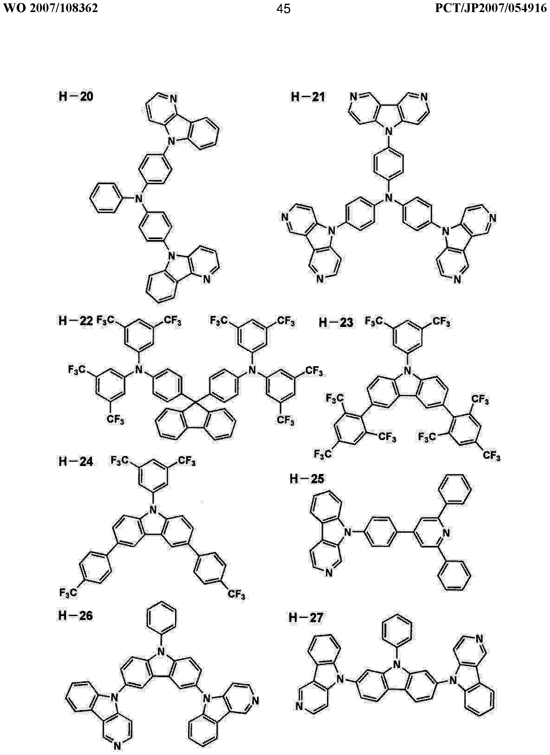
[0134] 請求の範囲第 1項〜第 4項、及び第 13項〜第 18項に記載の発明において、ホスト 化合物として用いられる化合物の具体例を以下に示す。 [0134] Specific examples of compounds used as the host compound in the inventions according to claims 1 to 4 and 13 to 18 are shown below.
[0135] [化 35] [0135] [Chemical 35]
[0136] [化 36] [0136] [Chemical 36]
[0137] [化 37]
[0137] [Chemical 37]
[0138] [化 38]
[0138] [Chemical 38]
[0139] [化 39]
[0139] [Chemical 39]
8 Z9£80動 OAV
8 Z9 £ 80 dynamic OAV
[0142] [化 42]
[0142] [Chemical 42]
また、請求の範囲第 5項〜第 18項の構成に係わる発明の有機エレクト口ルミネッセ ンス素子(以下、有機 EL素子ともいう)において、有機層の少なくとも 1層は燐光性化 合物および電子輸送性ホストイヒ合物を含有する発光層であり、該燐光性化合物の H OM〇が一5. 15〜一 3. 50eVかつ LUMOが一1. 25〜十 1. OOeVであり、該電子 輸送性ホストイ匕合物の励起三重項エネルギー T1が 2. 7eV以上である構成とするこ
とによって、本発明の第 2の課題である発光効率の高い有機 EL素子を得ることがで きた。また該有機 EL素子を用いて、照明装置、表示装置を得ることができた。 Further, in the organic electroluminescent device (hereinafter also referred to as an organic EL device) according to the invention according to the constitution of claims 5 to 18, at least one of the organic layers is a phosphorescent compound and an electron transport. The phosphorescent compound has a HOM of from 15.15 to 3.50 eV and a LUMO of from 1.25 to 10. 1. OOeV. The excitation triplet energy T1 of the compound must be 2.7 eV or more. As a result, the organic EL device having high luminous efficiency, which is the second problem of the present invention, can be obtained. In addition, an illumination device and a display device could be obtained using the organic EL element.
[0144] 以下、請求の範囲第 5項〜第 18項の構成に係わる発明に係る各構成要素の詳細 について、順次説明する。 [0144] Details of each component according to the invention relating to the configuration of claims 5 to 18 will be sequentially described below.
[0145] まず、本発明の HOMO, LUMOについて説明する。 [0145] First, HOMO and LUMO of the present invention will be described.
[0146] 本発明においても、前記同様、 HOMO, LUM〇の値は、米国 Gaussian社製の分 子軌道計算用ソフトウェアである Gaussian98 (Gaussian98、 Revision A. 11. 4, M. J. Frisch, et al, Gaussian, Inc., Pittsburgh PA, 2002. )を用いて計算 した時の値であり、キーワードとして B3LYP/LanL2DZを用いて構造最適化を行う ことにより算出した値 (eV単位換算値)と定義する。この計算値が有効な背景には、こ の手法で求めた計算値と実験値の相関が高いためである。 Also in the present invention, as described above, the values of HOMO and LUM 0 are Gaussian98 (Gaussian98, Revision A. 11.4, MJ Frisch, et al, Gaussian, software for molecular orbital calculation manufactured by Gaussian, USA). , Inc., Pittsburgh PA, 2002.) and is defined as a value (eV unit converted value) calculated by optimizing the structure using B3LYP / LanL2DZ as a keyword. The reason why this calculated value is effective is that there is a high correlation between the calculated value obtained by this method and the experimental value.
[0147] 請求の範囲第 5項〜第 18項の構成に係わる発明において、電子輸送性ホスト化合 物(以下、ホストイ匕合物ともいう)とは、電子移動度を μ 、正孔移動度を μ としたとき、 [0147] In the inventions according to the constitutions of claims 5 to 18, the electron transporting host compound (hereinafter also referred to as host compound) is the electron mobility μ and the hole mobility. where μ
e h e h
μ > β となるホストイ匕合物のことである。電子移動度/ 及び正孔移動度 μ はタイム e h e h ォブフライト (T. O. F)法により以下のように測定する。測定には、例えば、ォプテル 社製 TOF— 301を用いることができ、ホストの薄膜を ΙΤΟ半透明電極及び金属電極 間に挟んだ試料に、 ΙΤΟ側から照射したパルス波によって生成したシート状キャリア の過渡電流特性より電子移動度、正孔移動度が求められる。 It is a host compound where μ> β. Electron mobility / and hole mobility μ are measured by the time e he e h fob flight (T.O.F) method as follows. For example, OPTEL TOF-301 can be used for the measurement. A sample of a sheet-like carrier generated by a pulse wave irradiated from the heel side to a sample in which a thin film of a host is sandwiched between a semi-transparent electrode and a metal electrode. Electron mobility and hole mobility are obtained from the transient current characteristics.
[0148] 請求の範囲第 5項〜第 18項の構成に係わる発明において、励起 3重項エネルギー 準位 (T1)値は以下の式により定義する。 [0148] In the invention according to the constitution of claims 5 to 18, the excited triplet energy level (T1) value is defined by the following equation.
[0149] Χ= 1239. 8/Υ [0149] Χ = 1239. 8 / Υ
式中、 Xは励起三重項エネルギー(eV)、 Υはリン光の 0_0バンド(nm)を表す。リ ン光の 0— 0バンド(nm)は、下記のようにして求めることができる。 In the formula, X represents the excited triplet energy (eV), and Υ represents the 0_0 band (nm) of phosphorescence. The 0-0 band (nm) of phosphorous light can be obtained as follows.
[0150] 測定するホストイ匕合物を、よく脱酸素されたエタノール/メタノール =4/1 (vol/v ol)の混合溶媒に溶かし、リン光測定用セルに入れた後、液体窒素温度 77Kで励起 光を照射し、励起光照射後 100msでの発光スペクトルを測定する。リン光は蛍光に 比べ発光寿命が長いため、 100ms後に残存する光はほぼリン光であると考えること ができる。なお、リン光寿命が 100msより短い化合物に対しては遅延時間を短くして
測定しても構わないが、蛍光と区別できなくなるほど遅延時間を短くしてしまうとリン光 と蛍光が分離できないので問題となるため、その分離が可能な遅延時間を選択する 必要がある。 [0150] The host compound to be measured was dissolved in a well-deoxygenated ethanol / methanol = 4/1 (vol / vol) mixed solvent, placed in a phosphorescence measurement cell, and then at a liquid nitrogen temperature of 77K. Irradiate with excitation light and measure the emission spectrum at 100 ms after irradiation with excitation light. Since phosphorescence has a longer emission lifetime than fluorescence, it can be considered that the light remaining after 100 ms is almost phosphorescent. For compounds with a phosphorescence lifetime shorter than 100 ms, the delay time should be shortened. Measurement may be performed, but if the delay time is shortened so as to be indistinguishable from fluorescence, phosphorescence and fluorescence cannot be separated, which is a problem. Therefore, it is necessary to select a delay time that allows separation.
[0151] また、上記溶剤系で溶解できない化合物については、その化合物を溶解しうる任意 の溶剤を使用してもよい (実質上、上記測定法ではリン光波長の溶媒効果はごくわず かなので問題ない)。 [0151] In addition, for a compound that cannot be dissolved in the solvent system, any solvent that can dissolve the compound may be used (substantially the solvent effect of the phosphorescence wavelength is negligible in the measurement method described above. Absent).
[0152] 次に 0— 0バンドの求め方である力 本発明においては、上記測定法で得られたリ ン光スペクトルチャートの中で最も短波長側に現れる発光極大波長をもって 0— 0バ ンドと定義する。 [0152] Next, force that is a method for obtaining the 0-0 band In the present invention, the emission maximum wavelength that appears on the shortest wavelength side in the phosphor spectrum chart obtained by the above measurement method is 0-0 band. It is defined as
[0153] リン光スペクトルは通常強度が弱いことが多いため、拡大するとノイズとピークの判 別が難しくなるケースがある。このような場合には定常光スペクトルを拡大し、励起光 照射後 100ms後の発光スペクトル (便宜上これをリン光スペクトルと言う)と重ねあわ せリン光スぺタトノレに由来する定常光スペクトル部分からピーク波長を読み取ることで 決定すること力できる。また、リン光スぺクトノレをスムージング処理することでノイズとピ ークを分離しピーク波長を読み取ることもできる。なお、スムージング処理としては、 S avitzky&Golayの平滑化法等を適用することができる。 [0153] Since the phosphorescence spectrum usually has a low intensity, it may be difficult to distinguish between noise and peak when enlarged. In such a case, the steady-state light spectrum is expanded and overlapped with the emission spectrum 100 ms after irradiation with the excitation light (referred to as the phosphorescence spectrum for convenience), and peaks from the portion of the steady-state light spectrum derived from the phosphorescence spectrum. It can be determined by reading the wavelength. In addition, by smoothing the phosphorescence spectrum, it is possible to separate the noise and the peak and read the peak wavelength. As the smoothing process, a smoothing method such as Savitzky & Golay can be applied.
[0154] 《一般式 (I)で表される燐光性化合物》 [0154] <Phosphorescent compound represented by general formula (I)>
請求の範囲第 5項〜第 18項の構成に係わる発明の一般式 (I)で表される燐光性化 合物について説明する。 The phosphorescent compound represented by the general formula (I) of the invention relating to the constitution of claims 5 to 18 will be described.
[0155] 請求の範囲第 5項〜第 18項の構成に係わる発明の一般式 (I)で表される燐光性化 合物において、 HOMOが一 5· 15 3. 50eVかつ LUMOが一 1 · 25〜+ 1. 00 eVである。好ましくは HOMOが一4. 80〜一 3. 50eVかつ LUMOが一0. 80〜十 1. 00eVである。 [0155] In the phosphorescent compound represented by the general formula (I) of the invention relating to the constitution of claims 5 to 18, HOMO is 1 · 15 3.50eV and LUMO is 1 · 25 ~ + 1.00 eV. Preferably, the HOMO is from 1.80 to 3.50 eV and the LUMO is from 1.80 to 10.00 eV.
[0156] 請求の範囲第 5項〜第 18項の構成に係わる発明の一般式 (I)で表される燐光性化 合物において、 Rで表される置換基としては、例えばアルキル基 (例えば、メチル基、 [0156] In the phosphorescent compound represented by the general formula (I) of the invention relating to the constitution of claims 5 to 18, the substituent represented by R is, for example, an alkyl group (for example, , Methyl group,
1 1
ェチル基、プロピル基、イソプロピル基、 tert_ブチル基、ペンチル基、へキシル基、 ォクチル基、ドデシノレ基、トリデシル基、テトラデシル基、ペンタデシノレ基等)、シクロ アルキル基(例えば、シクロペンチル基、シクロへキシル基等)、アルケニル基(例え
ば、ビュル基、ァリル基等)、アルキニル基(例えば、ェチニル基、プロパルギル基等) 、芳香族炭化水素環基 (芳香族炭素環基、ァリール基等ともいい、例えば、フエニル 基、 p—クロロフヱニル基、メシチル基、トリル基、キシリル基、ナフチル基、アントリル 基、ァズレニル基、ァセナフテュル基、フルォレニル基、フエナントリル基、インデュル 基、ピレニル基、ビフエ二リル基等)、芳香族複素環基 (例えば、ピリジル基、ピリミジ ニル基、フリル基、ピロリル基、イミダゾリル基、ベンゾイミダゾリル基、ピラゾリル基、ピ ラジュノレ基、卜リアゾリノレ基(ί列免 ίΐ、 1, 2, 4一卜リ ゾ一ノレ一 1ーィノレ基、 1, 2, 3—卜 リアゾール _ 1 _ィル基等)、ォキサゾリル基、ベンゾォキサゾリル基、チアゾリル基、 イソォキサゾリル基、イソチアゾリル基、フラザニル基、チェニル基、キノリル基、ベン ゾフリノレ基、ジベンゾフリル基、ベンゾチェ二ル基、ジベンゾチェ二ル基、インドリル基 、カルバゾリル基、力ノレボリ二ノレ基、ジァザカルバゾリル基(前記カルボリニル基の力 ルポリン環を構成する炭素原子の一つが窒素原子で置き換わったものを示す)、キノ キサリニル基、ピリダジニル基、トリアジニル基、キナゾリニル基、フタラジェル基等)、 複素環基(例えば、ピロリジノレ基、イミダゾリジノレ基、モルホリル基、ォキサゾリジル基 等)、アルコキシ基(例えば、メトキシ基、エトキシ基、プロピルォキシ基、ペンチルォキ シ基、へキシルォキシ基、ォクチルォキシ基、ドデシノレォキシ基等)、シクロアルコキ シ基(例えば、シクロペンチルォキシ基、シクロへキシルォキシ基等)、ァリールォキシ 基(例えば、フエノキシ基、ナフチルォキシ基等)、アルキルチオ基(例えば、メチルチ ォ基、ェチルチオ基、プロピルチオ基、ペンチルチオ基、へキシルチオ基、ォクチル チォ基、ドデシノレチォ基等)、シクロアルキルチオ基(例えば、シクロペンチルチオ基 、シクロへキシノレチォ基等)、ァリールチオ基(例えば、フエ二ルチオ基、ナフチルチ ォ基等)、アルコキシカルボニル基(例えば、メチルォキシカルボニル基、ェチルォキ シカルボニル基、ブチルォキシカルボニル基、ォクチルォキシカルボニル基、ドデシ ルォキシカルボニル基等)、ァリールォキシカルボニル基(例えば、フエニルォキシカ ルボニル基、ナフチルォキシカルボニル基等)、スルファモイル基(例えば、アミノスノレ ホニル基、メチルアミノスルホニル基、ジメチルアミノスルホニル基、ブチルアミノスル ホニル基、へキシルアミノスルホニル基、シクロへキシルアミノスルホニル基、ォクチル アミノスルホニル基、ドデシルアミノスルホニル基、フエニルアミノスルホニル基、ナフ
チルアミノスルホニル基、 2—ピリジルアミノスルホニル基等)、ァシル基(例えば、ァセ チノレ基、ェチルカルボニル基、プロピルカルボニル基、ペンチルカルボニル基、シク 口へキシルカルボニル基、ォクチルカルボニル基、 2—ェチルへキシルカルボニル基 、ドデシルカルボ二ル基、フエニルカルボニル基、ナフチルカルボニル基、ピリジルカ ルボニル基等)、ァシルォキシ基(例えば、ァセチルォキシ基、ェチルカルボニルォ キシ基、ブチルカルボニルォキシ基、ォクチルカルボニルォキシ基、ドデシルカルボ ニルォキシ基、フエニルカルボニルォキシ基等)、アミド基(例えば、メチルカルボニル アミノ基、ェチルカルボニルァミノ基、ジメチルカルボニルァミノ基、プロピルカルボ二 ノレアミノ基、ペンチルカルボニルァミノ基、シクロへキシルカルボニルァミノ基、 2—ェ チルへキシルカルボニルァミノ基、ォクチルカルボニルァミノ基、ドデシルカルボニル アミノ基、フエニルカルボニルァミノ基、ナフチルカルボニルァミノ基等)、力ルバモイ ル基(例えば、ァミノカルボニル基、メチルァミノカルボニル基、ジメチルァミノカルボ ニル基、プロピルアミノカルボニル基、ペンチルァミノカルボニル基、シクロへキシル ァミノカルボニル基、ォクチルァミノカルボニル基、 2—ェチルへキシルァミノカルボ二 ル基、ドデシルァミノカルボニル基、フエニルァミノカルボニル基、ナフチルァミノカル ボニル基、 2—ピリジルァミノカルボニル基等)、ウレイド基(例えば、メチルウレイド基 、ェチルウレイド基、ペンチルゥレイド基、シクロへキシルウレイド基、ォクチルゥレイド 基、ドデシルゥレイド基、フエニルウレイド基ナフチルウレイド基、 2—ピリジノレアミノウ レイド基等)、スルフィエル基(例えば、メチルスルフィエル基、ェチルスルフィニル基 、ブチルスルフィニル基、シクロへキシルスルフィニル基、 2—ェチルへキシルスルフ ィニル基、ドデシルスルフィニル基、フエニルスルフィニル基、ナフチルスルフィニル 基、 2 _ピリジルスルフィエル基等)、アルキルスルホニル基(例えば、メチルスルホニ ル基、ェチルスルホニル基、ブチルスルホニル基、シクロへキシルスルホニル基、 2_ ェチルへキシルスルホニル基、ドデシルスルホニル基等)、ァリールスルホニル基ま たはへテロアリールスルホニル基(例えば、フエニルスルホニル基、ナフチルスルホニ ル基、 2_ピリジルスルホニル基等)、アミノ基(例えば、アミノ基、ェチルァミノ基、ジメ チノレアミノ基、ブチルァミノ基、シクロペンチルァミノ基、 2—ェチルへキシルァミノ基、 ドデシノレアミノ基、ァニリノ基、ナフチノレアミノ基、 2—ピリジノレ ミノ基等)、シ ノ基、
ニトロ基、ヒドロキシ基、メルカプト基、シリル基(例えば、トリメチルシリル基、トリイソプ 口ビルシリル基、トリフエエルシリル基、フエ二ルジェチルシリル基等)等が挙げられる Ethyl group, propyl group, isopropyl group, tert_butyl group, pentyl group, hexyl group, octyl group, dodecinole group, tridecyl group, tetradecyl group, pentadecinole group, etc.), cycloalkyl group (for example, cyclopentyl group, cyclohexyl group) Groups), alkenyl groups (eg For example, butyl group, aryl group, etc.), alkynyl group (for example, ethynyl group, propargyl group, etc.), aromatic hydrocarbon ring group (aromatic carbocyclic group, aryl group, etc., for example, phenyl group, p-chlorophenyl) Group, mesityl group, tolyl group, xylyl group, xylyl group, naphthyl group, anthryl group, azulenyl group, acenaphthyl group, fluorenyl group, phenanthryl group, indur group, pyrenyl group, biphenylyl group, etc.), aromatic heterocyclic group (for example, Pyridyl group, pyrimidinyl group, furyl group, pyrrolyl group, imidazolyl group, benzoimidazolyl group, pyrazolyl group, pyrajonole group, triazolinole group (ί column, 1, 2, 4 1, 2, 3— 卜 riazole _ 1 _yl group, etc.), oxazolyl group, benzoxazolyl group, thiazolyl group, isoxazol Group, isothiazolyl group, furazanyl group, chenyl group, quinolyl group, benzofurinole group, dibenzofuryl group, benzochelyl group, dibenzochelyl group, indolyl group, carbazolyl group, force norbinolinole group, diazacarbazolyl Group (where one of the carbon atoms constituting the force of the carbolinyl group is replaced by a nitrogen atom), a quinoxalinyl group, a pyridazinyl group, a triazinyl group, a quinazolinyl group, a phthalagel group, etc.), a heterocyclic group ( For example, pyrrolidinole group, imidazolidinole group, morpholyl group, oxazolidyl group, etc.), alkoxy group (eg, methoxy group, ethoxy group, propyloxy group, pentyloxy group, hexyloxy group, octyloxy group, dodecinoreoxy group, etc.), cycloalkoxy group ( For example, cyclopent Oxy group, cyclohexyloxy group, etc.), aryloxy group (for example, phenoxy group, naphthyloxy group, etc.), alkylthio group (for example, methylthio group, ethylthio group, propylthio group, pentylthio group, hexylthio group, octylthio group, dodecinoretio group) Group), cycloalkylthio group (eg, cyclopentylthio group, cyclohexylenothio group, etc.), arylthio group (eg, phenylthio group, naphthylthio group, etc.), alkoxycarbonyl group (eg, methyloxycarbonyl group, ethyloxy group, etc.) Sicarbonyl group, butyloxycarbonyl group, octyloxycarbonyl group, dodecyloxycarbonyl group, etc.), aryloxycarbonyl group (for example, phenylcarbonyl group, naphthyloxycarbonyl group, etc.), sulfamoyl group (For example, aminosulphonyl group, methylaminosulfonyl group, dimethylaminosulfonyl group, butylaminosulfonyl group, hexylaminosulfonyl group, cyclohexylaminosulfonyl group, octylaminosulfonyl group, dodecylaminosulfonyl group, phenylaminosulfonyl group) Group, naphth Tilaminosulfonyl group, 2-pyridylaminosulfonyl group, etc.), acyl groups (eg acetyleno group, ethylcarbonyl group, propylcarbonyl group, pentylcarbonyl group, cyclohexylcarbonyl group, octylcarbonyl group, 2- Ethylhexylcarbonyl group, dodecylcarbonyl group, phenylcarbonyl group, naphthylcarbonyl group, pyridylcarbonyl group, etc.), acyloxy group (eg, acetyloxy group, ethylcarbonyloxy group, butylcarbonyloxy group, octyl group) Carbonyloxy group, dodecylcarbonyloxy group, phenylcarbonyloxy group, etc.), amide group (for example, methylcarbonylamino group, ethylcarbonylamino group, dimethylcarbonylamino group, propylcarbonylaminoamino group, pentylcarbonyl group) Amami Groups, cyclohexylcarbonylamino groups, 2-ethylhexylcarbonylamino groups, octylcarbonylamino groups, dodecylcarbonylamino groups, phenylcarbonylamino groups, naphthylcarbonylamino groups, and the like. Group (for example, aminocarbonyl group, methylaminocarbonyl group, dimethylaminocarbonyl group, propylaminocarbonyl group, pentylaminocarbonyl group, cyclohexylaminocarbonyl group, octylaminocarbonyl group, 2 —Ethylhexylaminocarbonyl group, dodecylaminocarbonyl group, phenylaminocarbonyl group, naphthylaminocarbonyl group, 2-pyridylaminocarbonyl group, etc.), ureido group (for example, methylureido group, Ethylureido group, pentylureido group, cyclohexylurei group Group, octylureido group, dodecylureido group, phenylureido group, naphthylureido group, 2-pyridinoreaminoureido group, etc., sulfier group (eg, methylsulfenyl group, ethylsulfinyl group, butylsulfinyl group, cyclohexyl) Sulfinyl group, 2-ethylhexylsulfinyl group, dodecylsulfinyl group, phenylsulfinyl group, naphthylsulfinyl group, 2_pyridylsulfiel group, etc.), alkylsulfonyl group (for example, methylsulfonyl group, ethylsulfonyl group, butylsulfonyl) Group, cyclohexylsulfonyl group, 2_ethylhexylsulfonyl group, dodecylsulfonyl group, etc.), arylsulfonyl group or heteroarylsulfonyl group (for example, phenylsulfonyl group, naphthylsulfonyl group, 2_phenyl group). A disulfonyl group, etc.), an amino group (for example, an amino group, an ethylamino group, a dimethylenoamino group, a butylamino group, a cyclopentylamino group, a 2-ethylhexylamino group, a dodecinoreamino group, an anilino group, a naphthinoreamino group, a 2-pyridinoremino group. Etc.), syno groups, Nitro group, hydroxy group, mercapto group, silyl group (for example, trimethylsilyl group, triisopropyl silyl group, triphenylsilyl group, phenylethylsilyl group, etc.)
[0157] これらの置換基のうち、好ましいものはアルキル基もしくはァリール基である。 Of these substituents, preferred are an alkyl group and an aryl group.
[0158] Zは 5〜7員環を形成するのに必要な非金属原子群を表す。 Zにより形成される 5〜 7員環としては、例えば、ベンゼン環、ナフタレン環、ピリジン環、ピリミジン環、ピロ一 ル環、チォフェン環、ピラゾール環、イミダゾール環、ォキサゾール環及びチアゾール 環等が挙げられる。これらのうちで好ましいものは、ベンゼン環である。 [0158] Z represents a nonmetallic atom group necessary for forming a 5- to 7-membered ring. Examples of the 5- to 7-membered ring formed by Z include a benzene ring, naphthalene ring, pyridine ring, pyrimidine ring, pyrrole ring, thiophene ring, pyrazole ring, imidazole ring, oxazole ring, and thiazole ring. . Of these, a benzene ring is preferred.
[0159] B〜Bは炭素原子、窒素原子、酸素原子もしくは硫黄原子を表し、少なくとも一つ [0159] B to B represent a carbon atom, a nitrogen atom, an oxygen atom or a sulfur atom, and at least one of them
1 5 1 5
は窒素原子を表す。これら 5つの原子により形成される芳香族含窒素複素環としては 単環が好ましい。例えば、ピロール環、ピラゾール環、イミダゾール環、トリァゾール環 、テトラゾール環、ォキサゾール環、イソォキサゾール環、チアゾール環、イソチアゾ ール環、ォキサジァゾール環及びチアジアゾ一環ル等が挙げられる。これらのうちで 好ましいものは、ピラゾール環、イミダゾール環であり、さらに好ましくはイミダゾール 環である。これらの環は上記の置換基によって更に置換されていてもよレ、。置換基と して好ましいものはアルキル基およびァリール基であり、さらに好ましくは、置換アル キル基および無置換ァリール基である。 Represents a nitrogen atom. The aromatic nitrogen-containing heterocycle formed by these five atoms is preferably a monocycle. Examples thereof include a pyrrole ring, a pyrazole ring, an imidazole ring, a triazole ring, a tetrazole ring, an oxazole ring, an isoxazole ring, a thiazole ring, an isothiazol ring, an oxadiazole ring, and a thiadiazole ring. Among these, a pyrazole ring and an imidazole ring are preferable, and an imidazole ring is more preferable. These rings may be further substituted with the above substituents. Preferred examples of the substituent are an alkyl group and an aryl group, and more preferred are a substituted alkyl group and an unsubstituted aryl group.
[0160] Lは X、 Xと共に 2座の配位子を形成する原子群を表す。 X— L—Xで表される 2 [0160] L represents an atomic group which forms a bidentate ligand with X and X. X—L—X 2
1 1 2 1 1 2 座の配位子の具体例としては、例えば、置換または無置換のフエ二ルビリジン、フエ 二ルビラゾール、フエ二ルイミダゾール、フエニルトリァゾール、フエ二ルテトラゾール、 ビラザボール、ピコリン酸及びァセチルアセトン等が挙げられる。 Specific examples of 1 1 2 1 1 2 bidentate ligands include, for example, substituted or unsubstituted phenylviridine, phenylvirazole, phenylimidazole, phenyltriazole, phenyltetrazole, virazorbol, picoline. Examples include acid and acetylacetone.
[0161] これらの基は上記の置換基によって更に置換されていてもよい。 [0161] These groups may be further substituted with the above-described substituents.
[0162] mlは 1、 2または 3の整数を表し、 m2は 0、 1または 2の整数を表す力 ml +m2は[0162] ml represents an integer of 1, 2 or 3, m2 represents a force of 0, 1 or 2 ml + m2 is
2または 3である。中でも、 m2は 0である場合が好ましい。 2 or 3. Of these, m2 is preferably 0.
[0163] Mで表される金属としては、元素周期表の 8族〜 10族の遷移金属元素(単に遷移 [0163] The metal represented by M includes transition metal elements of Group 8 to Group 10 of the Periodic Table of Elements (simply transition
1 1
金属ともいう)が用いられるが、中でも、イリジウム、白金が好ましぐさらに好ましくはィ リジゥムである。 Of these, iridium and platinum are preferred, and iridium is more preferred.
[0164] なお本発明の一般式 (I)で表される燐光性化合物は、重合性基または反応性基を
有してレ、てもいなくてもょレ、。 [0164] The phosphorescent compound represented by the general formula (I) of the present invention has a polymerizable group or a reactive group. I have it, I don't need it.
[0165] また、 B〜Bで形成される含窒素複素環がイミダゾール環が好ましぐイミダゾール [0165] Further, the nitrogen-containing heterocycle formed by B to B is preferably an imidazole ring.
1 5 1 5
環の場合、前記一般式 (I)は前記一般式 (Π)で表されることがより好ましい。 In the case of a ring, the general formula (I) is more preferably represented by the general formula (Π).
[0166] 一般式 (Π)において、 R、 R、 Rは置換基を表す。 Zは 5〜7員環を形成するのに [0166] In the general formula (R), R, R, and R represent a substituent. Z forms a 5- to 7-membered ring
1 2 3 one two Three
必要な非金属原子群を表す。 nlは 0〜5の整数を表す。 Mは元素周期表における 8 Represents the necessary nonmetallic atom group. nl represents an integer of 0 to 5. M is 8 in the periodic table
1 1
族〜 10族の金属を表す。 Xおよび Xは炭素原子、窒素原子もしくは酸素原子を表し Represents Group 10 to Group 10 metals. X and X represent a carbon atom, a nitrogen atom or an oxygen atom
1 2 1 2
、 Lは Xおよび Xとともに 2座の配位子を形成する原子群を表す。 mlは 1、 2または , L represents a group of atoms that together with X and X form a bidentate ligand. ml is 1, 2 or
1 1 2 1 1 2
3の整数を表し、 m2は 0、 1または 2の整数を表す力 ml +m2は 2または 3である。 Represents an integer of 3, m2 represents an integer of 0, 1 or 2 ml + m2 is 2 or 3.
[0167] 一般式 (Π)において、 R、 R、 Rで表される置換基は前記一般式 (II)における R [0167] In the general formula (Π), the substituents represented by R, R, and R are R in the general formula (II).
1 2 3 1 で表される置換基と同義である。また、 Z、 M、 Xおよび X、 L等についても前記一 It is synonymous with the substituent represented by 1 2 3 1. In addition, Z, M, X and X, L, etc.
1 1 2 1 1 1 2 1
般式(I)におけるものと同義である。また、 ml、 m2も同義である。 It is synonymous with the formula (I). Moreover, ml and m2 are also synonymous.
[0168] また、一般式 (Π)の Rで表される基として、芳香族炭化水素環基 (芳香族炭素環基 [0168] In addition, as the group represented by R in the general formula (Π), an aromatic hydrocarbon ring group (aromatic carbocyclic group)
2 2
)が好ましぐなかでも置換ァリール基が好ましぐ置換ァリールとして下記一般式 (III The preferred general formula (III) is a substituted aryl group in which a substituted aryl group is preferred.
)で表される基が好ましい。 ) Is preferred.
[0169] [化 43] 一般式 (ΙΠ) [0169] [Chemical formula 43] General formula (ΙΠ)
[0170] 一般式 (ΠΙ)において、 Rは、立体パラメータ値 (Es値)が—0. 5以下の置換基を表 [0170] In the general formula (ΠΙ), R represents a substituent having a steric parameter value (Es value) of -0.5 or less.
4 Four
す。 Rは Rと同じで、 n5は 0〜4の整数を表す。尚、 *は結合位置を表す。 The R is the same as R, and n5 represents an integer of 0-4. Note that * represents a binding position.
5 1 5 1
[0171] ここで、 Es値とは化学反応性より誘導された立体パラメータであり、この値が小さけ れば小さいほど立体的に嵩高い置換基ということができる。 [0171] Here, the Es value is a steric parameter derived from chemical reactivity, and the smaller this value, the more sterically bulky the substituent.
[0172] Es値については前述した。 [0172] The Es value has been described above.
[0173] Rは、立体パラメータ値 (Es値)がー 0. 5以下の置換基を表す。 [0173] R represents a substituent having a steric parameter value (Es value) of -0.5 or less.
4 Four
好ましくは 7. 0以上 0. 6以下であり、最も好ましくは 7. 0以上 1. 0以下であ る。
[0174] また、 Rに、例えば、ケトーエノール互変異性体が存在し得る場合、ケト部分はエノIt is preferably 7.0 or more and 0.6 or less, and most preferably 7.0 or more and 1.0 or less. [0174] In addition, for example, when a ketoeenol tautomer may exist in R, the keto moiety is
4 Four
ールの異性体として Es値を換算している。他の互変異性が存在する場合も同様の換 算方法にぉレ、て Es値を換算する。 Es value is converted as an isomer of diols. If other tautomers exist, convert the Es value using the same conversion method.
[0175] 以下に本発明の一般式 (1)、また一般式 (II)で表される燐光性化合物の具体的な 例を挙げるが、本発明はこれらに限定されるものではない。 [0175] Specific examples of the phosphorescent compound represented by the general formula (1) and the general formula (II) of the present invention are given below, but the present invention is not limited to these.
[0176] 本発明の一般式 (1)、また一般式 (Π)で表される燐光性化合物の具体的例としては[0176] Specific examples of the phosphorescent compound represented by the general formula (1) and the general formula (一般) of the present invention include
、前記一般式(1)、また一般式 (Π)で表される燐光性化合物としてあげられた、 ィ匕合物 No. 1—:!〜 1一 59及び 1一 75〜1 _ 107のィ匕合物、 The compound Nos. 1— :! to 1 1 59 and 1 1 to 75 1 _107, which are mentioned as phosphorescent compounds represented by the general formula (1) and the general formula (Π). Compound,
また、下記化合物があげられる。 Moreover, the following compound is mention | raise | lifted.
[0177] [化 44]
[0177] [Chemical 44]
[S [8 I0] [S [8 I0]
89 Z9£80動 OAV
-70 1-71 89 Z9 £ 80 OAV -70 1-71
-109 -109
[0180] これらの金属錯体も前記一般式(1)で表される燐光性化合物と同様の参考文献、 更にそれらの文献中に記載の参考文献等の方法を適用することにより合成できる。 [0180] These metal complexes can also be synthesized by applying the same references as the phosphorescent compound represented by the general formula (1), and also the methods such as the references described in these references.
[0181] 次に、請求の範囲第 5項〜第 18項の構成に係わる発明の有機 EL素子の構成層 について詳細に説明する。 [0181] Next, the constituent layers of the organic EL element of the invention according to the constitutions of claims 5 to 18 will be described in detail.
[0182] 本発明において、請求の範囲第 5項〜第 18項に係わる有機 EL素子の層構成の好 ましい具体例を以下に示すが、本発明はこれらに限定されない。 [0182] In the present invention, preferred specific examples of the layer structure of the organic EL device according to claims 5 to 18 are shown below, but the present invention is not limited thereto.
(i)陽極 Z発光層 Z陰極 (i) Anode Z Light emitting layer Z cathode
(ii)陽極/正孔輸送層/発光層/陰極 (ii) Anode / hole transport layer / light emitting layer / cathode
(iii)陽極/正孔輸送層/発光層/電子輸送層/陰極 (iii) Anode / hole transport layer / light emitting layer / electron transport layer / cathode
(iv)陽極/正孔注入層/正孔輸送層/発光層 Z電子輸送層 Z陰極バッファ一層 層/陰極 (V)陽極/正孔輸送層/正孔輸送層 A/発光層/電子輸送層/陰極バ ッファー層/陰極 (vi)陽極/正孔輸送層/正孔輸送層 AZ発光層 Z電子輸送層 A /電子輸送層/陰極バッファー層/陰極 (iv) Anode / hole injection layer / hole transport layer / light emitting layer Z electron transport layer Z cathode buffer layer / cathode (V) Anode / hole transport layer / hole transport layer A / light emitting layer / electron transport layer / Cathode buffer layer / cathode (vi) Anode / hole transport layer / hole transport layer AZ emitting layer Z electron transport layer A / electron transport layer / cathode buffer layer / cathode
《発光層》 <Light emitting layer>
請求の範囲第 5項〜第 18項の構成本発明に係る発光層について説明する。 Structures of Claims 5 to 18 The light emitting layer according to the present invention will be described.
[0183] 本発明の請求の範囲第 5項〜第 18項の記載の構成に係る発光層は、電極または 電子輸送層、正孔輸送層等から注入されてくる電子及び正孔が再結合して発光する 層であり、発光する部分は発光層の層内であっても発光層と隣接層との界面であつ てもよい。 [0183] In the light emitting layer according to the constitution of claims 5 to 18 of the present invention, electrons and holes injected from an electrode or an electron transport layer, a hole transport layer, etc. are recombined. The light emitting portion may be in the light emitting layer or at the interface between the light emitting layer and the adjacent layer.
[0184] (燐光性化合物(リン光性ドーパント、リン光発光性化合物ともいう)) [0184] (Phosphorescent compound (also referred to as phosphorescent dopant or phosphorescent compound))
本発明の有機 EL素子の発光層には、燐光性化合物(リン光性ドーパント、リン光発 光性化合物ともいう)とホスト化合物が含有される。本発明においては、燐光性化合 物として前述した本発明に係る化合物を用いることが好ましい。 The light emitting layer of the organic EL device of the present invention contains a phosphorescent compound (also referred to as a phosphorescent dopant or a phosphorescent compound) and a host compound. In the present invention, it is preferable to use the compound according to the present invention described above as the phosphorescent compound.
更に公知の燐光性化合物を複数種併用してもよい。リン光性ドーパントを複数種用 レ、ることで、異なる発光を混ぜることが可能となり、これにより任意の発光色を得ること ができる。リン光性ドーパントの種類、ドープ量を調整することで白色発光が可能であ り、照明、ノ ックライトへの応用もできる。 Further, a plurality of known phosphorescent compounds may be used in combination. By using multiple types of phosphorescent dopants, it is possible to mix different light emissions, and thus any light emission color can be obtained. White light emission is possible by adjusting the type and amount of phosphorescent dopant, and it can also be applied to lighting and knocklights.
[0185] 公知の燐光性化合物の具体例としては、以下の文献に記載されている化合物が挙
げられる。 [0185] Specific examples of known phosphorescent compounds include compounds described in the following documents. I can get lost.
[0186] 国際公開第 00/70655号パンフレット、特開 2002— 280178号公報、特開 2001 [0186] WO 00/70655 pamphlet, JP 2002-280178 A, JP 2001
— 181616号公報、特開 2002— 280179号公報、特開 2001— 181617号公報、 特開 2002— 280180号公報、特開 2001— 247859号公報、特開 2002— 299060 号公報、特開 2001— 313178号公報、特開 2002— 302671号公報、特開 2001— 345183号公報、特開 2002— 324679号公報、国際公開第 02/15645号パンフ レット、特開 2002— 332291号公報、特開 2002— 50484号公報、特開 2002— 33 2292号公報、特開 2002— 83684号公報、特表 2002— 540572号公報、特開 20 02— 117978号公報、特開 2002— 338588号公報、特開 2002— 170684号公報 、特開 2002— 352960号公報、国際公開第 01/93642号パンフレット、特開 2002— No. 181616, No. 2002-280179, No. 2001-181617, No. 2002-280180, No. 2001-247859, No. 2002-299060, No. 2001-313178 No., JP 2002-302671, JP 2001-345183, JP 2002-324679, WO 02/15645, JP 2002-332291, JP 2002-50484. No., JP 2002-33 2292, JP 2002-83684, JP 2002-540572, JP 20 02-117978, JP 2002-338588, JP 2002-170684 No., JP 2002-352960 A, WO 01/93642 pamphlet, JP 2002
— 50483号公報、特開 2002— 100476号公報、特開 2002— 173674号公報、特 開 2002— 359082号公報、特開 2002— 175884号公報、特開 2002— 363552号 公報、特開 2002— 184582号公報、特開 2003— 7469号公報、特表 2002— 525 808号公報、特開 2003— 7471号公報、特表 2002— 525833号公報、特開 2003— 50483, JP 2002-100476, JP 2002-173674, JP 2002-359082, JP 2002-175884, JP 2002-363552, JP 2002-184582 Publication, JP 2003-7469, JP 2002-525 808, JP 2003-7471, JP 2002-525833, JP 2003
— 31366号公報、特開 2002— 226495号公報、特開 2002— 234894号公報、特 開 2002— 235076号公報、特開 2002— 241751号公報、特開 2001— 319779号 公報、特開 2001— 319780号公報、特開 2002— 62824号公報、特開 2002— 10 0474号公報、特開 2002— 203679号公報、特開 2002— 343572号公報、特開 2 002— 203678号公報等。 — 31366, JP 2002-226495, JP 2002-234894, JP 2002-235076, JP 2002-241751, JP 2001-319779, JP 2001-319780 JP, 2002-62824, JP 2002-10474, JP 2002-203679, JP 2002-343572, JP 2002-203678, and the like.
[0187] (発光ホスト化合物) [0187] (Luminescent host compound)
発光層に使用される材料としては、上記の燐光性ドーパントの他に発光ホス M匕合 物がある。 As a material used for the light emitting layer, there is a light emitting phosphine compound in addition to the above phosphorescent dopant.
[0188] ここで、本発明においてホストイ匕合物とは、発光層に含有される化合物のうちで室 温(25°C)においてリン光発光のリン光量子収率力 0. 01未満の化合物と定義され る。請求の範囲第 5項〜第 18項の記載の構成に係る発明においては、ホスト化合物 として電子輸送性ホストイ匕合物を用いることが好ましい。これにより、よりいつそう連続 駆動時の素子の発光寿命を長くすることができる。 [0188] Here, in the present invention, the host compound is a compound having a phosphorescence quantum yield power of less than 0.01 of phosphorescence emission at room temperature (25 ° C) among compounds contained in the light emitting layer. Defined. In the invention according to the constitution described in claims 5 to 18, it is preferable to use an electron transporting host compound as the host compound. This makes it possible to extend the light emission lifetime of the element during continuous driving more frequently.
[0189] 本発明において、電子輸送性ホストイ匕合物(以下、ホストイ匕合物ともいう)とは、前述
したように、電子移動度を μ 、正孔移動度を/ としたとき、 μ > μ となるホストイ匕合 In the present invention, the electron transporting host compound (hereinafter also referred to as host compound) is the above-mentioned As shown above, when the electron mobility is μ and the hole mobility is /, the host condition is such that μ> μ.
e h e h e h e h
物のことである。 It is a thing.
[0190] 請求の範囲第 5項〜第 18項の記載の構成に係る発明に用いられる発光ホスト化合 物としては、構造的には特に制限は無いが、代表的にはカルボリン誘導体、ジァザ力 ルバゾール誘導体、芳香族ボラン誘導体、ォキサジァゾール誘導体、力ルバゾール 誘導体等が挙げられる。 [0190] The luminescent host compound used in the invention according to the constitution described in claims 5 to 18 is not particularly limited in terms of structure, but is typically a carboline derivative or diaza-powered rubazole. Derivatives, aromatic borane derivatives, oxadiazole derivatives, force rubazole derivatives and the like.
[0191] 以下にカルボリン誘導体、ジァザ力ルバゾール誘導体、芳香族ボラン誘導体の具 体例を挙げるが、本発明はこれらに限定されない。 [0191] Specific examples of the carboline derivative, diaza force rubazole derivative, and aromatic borane derivative are given below, but the present invention is not limited thereto.
[0192] [化 47]
[0192] [Chemical 47]
[0193] [化 48]
[0193] [Chemical 48]
[0194] [化 49]
[0194] [Chemical 49]
[0195] [化 50]
[0195] [Chemical 50]
[0196] [化 51]
[Ζ^ [Ζ6Ϊ0] [0196] [Chemical 51] [Ζ ^ [Ζ6Ϊ0]
l6f-S0/ .00idf/X3d 19 Z9C80I/Z,00i ΟΛ\
l6f-S0 / .00idf / X3d 19 Z9C80I / Z, 00i ΟΛ \
[0198] [化 53]
[0198] [Chemical 53]
[0199] [化 54]
[0199] [Chemical 54]
[0200] [化 55]
[0200] [Chemical 55]
[0201] 発光ホストイ匕合物としては、発光の長波長化を防ぎ、なお且つ高 Tg (ガラス転移温 度)である化合物が好ましい。 [0201] As the luminescent host compound, a compound that prevents the emission of light from being long-wavelength and has a high Tg (glass transition temperature) is preferable.
[0202] 発光ホスト化合物の具体例としては、以下の文献に記載されている化合物が好適
である。例えば、特開 2002— 308855号公報、同 2002— 319491号公報、同 200[0202] As specific examples of the luminescent host compound, compounds described in the following documents are preferred. It is. For example, JP-A-2002-308855, 2002-319491, 200
1— 357977号公報、同 2002— 334786号公報、同 2002— 334787号公報、同 21-357977, 2002-334786, 2002-334787, 2
002— 15871号公報、同 2002— 334788号公報、同 2002— 43056号公報、同 2 002— 334789号公報、同 2002— 338579号公報、同 2002— 343568号公報、 同 2002— 141173号公報、同 2002— 352957号公報、同 2002— 203683号公報 、同 2002— 363227号公報、同 2002— 231453号公報、同 2003— 3165号公報 、同 2003— 27048号公報、同 2002— 260861号公報、同 2002— 299060号公 報、同 2002— 302516号公報、同 2002— 305083号公報、同 2002— 305084号 公報、同 2005— 340123号公報、同 2004— 234952公報等。 002-15871, 2002-334788, 2002-43056, 2 002-334789, 2002-338579, 2002-343568, 2002-141173, 2002-352957, 2002-203683, 2002-363227, 2002-231453, 2003-3165, 2003-27048, 2002-260861, 2002 — Publication No. 299060, Publication No. 2002-302516, Publication No. 2002-305083, Publication No. 2002-305084, Publication No. 2005-340123, Publication No. 2004-234952, etc.
[0203] 次に、代表的な有機 EL素子の構成について述べる。 [0203] Next, a configuration of a typical organic EL element will be described.
[0204] 《有機 EL素子の構成層》 [0204] 《Organic EL device components》
本発明の有機 EL素子の構成層について説明する。 The constituent layers of the organic EL device of the present invention will be described.
[0205] 本発明の有機 EL素子の層構成の好ましい具体例を以下に示す力 本発明はこれ らに限定されない。 [0205] Preferable specific examples of the layer structure of the organic EL device of the present invention are as follows. The present invention is not limited thereto.
[0206] (i)陽極/正孔輸送層/発光層/正孔阻止層/電子輸送層/陰極 [0206] (i) Anode / hole transport layer / light emitting layer / hole blocking layer / electron transport layer / cathode
(ii)陽極/電子阻止層/発光層/正孔阻止層/電子輸送層/陰極 (ii) Anode / electron blocking layer / light emitting layer / hole blocking layer / electron transport layer / cathode
(m)陽極/正孔輸送層/電子阻止層/発光層/正孔阻止層/電子輸送層/陰 極 (m) Anode / hole transport layer / electron blocking layer / light emitting layer / hole blocking layer / electron transport layer / negative electrode
(iv)陽極/正孔輸送層/電子阻止層/発光層/正孔阻止層/電子輸送層/陰 極 (iv) Anode / hole transport layer / electron blocking layer / light emitting layer / hole blocking layer / electron transport layer / cathode
(V)陽極/正孔輸送層/電子阻止層/発光層/正孔阻止層/電子輸送層/陰 極バッファー層/陰極 (V) Anode / hole transport layer / electron blocking layer / light emitting layer / hole blocking layer / electron transport layer / cathode buffer layer / cathode
(vi)陽極/陽極バッファ一層/正孔輸送層/電子阻止層/発光層/正孔阻止層 (vi) Anode / anode buffer layer / hole transport layer / electron blocking layer / light emitting layer / hole blocking layer
/電子輸送層/陰極バッファー層/陰極 / Electron transport layer / cathode buffer layer / cathode
(vii)陽極/陽極バッファ一層/正孔輸送層/電子阻止層/発光層/正孔阻止層 (vii) Anode / anode buffer layer / hole transport layer / electron blocking layer / light emitting layer / hole blocking layer
/電子輸送層/陰極バッファー層/陰極 / Electron transport layer / cathode buffer layer / cathode
(viii)陽極/正孔輸送層/中間層/発光層/正孔阻止層/電子輸送層/陰極バ ッファー層/陰極
この中でも、請求の範囲第 1項〜第 4項、及び第 13項〜第 18項の構成に係わる発 明におレ、ては (vm)の構成が最も好ましレ、。 (viii) Anode / hole transport layer / intermediate layer / light emitting layer / hole blocking layer / electron transport layer / cathode buffer layer / cathode Among these, the configuration according to claims 1 to 4 and 13 to 18 is preferred, and ( v m) is the most preferable.
[0207] 《中間層》 [0207] 《Middle layer》
本発明に係る中間層とは発光層と正孔輸送層との間の層のことである。該層に含ま れる材料の性質によっては、該層を正孔輸送層と呼ぶこともあり、電子阻止層と呼ぶ こともある。本発明においては、該中間層中に発光層に含有されるホストイ匕合物と同 じ材料を含有することが好ましレ、。 The intermediate layer according to the present invention is a layer between the light emitting layer and the hole transport layer. Depending on the nature of the material contained in the layer, the layer may be referred to as a hole transport layer or an electron blocking layer. In the present invention, the intermediate layer preferably contains the same material as the host compound contained in the light emitting layer.
[0208] 《阻止層(電子阻止層、正孔阻止層)》 [0208] << Blocking layer (electron blocking layer, hole blocking layer) >>
本発明に係る阻止層(例えば、電子阻止層、正孔阻止層)について説明する。 The blocking layer (for example, electron blocking layer, hole blocking layer) according to the present invention will be described.
[0209] 本発明に係る阻止層の膜厚としては好ましくは 3〜: !OOnmであり、更に好ましくは 5 〜30nmである。 [0209] The thickness of the blocking layer according to the present invention is preferably 3 to:! OOnm, and more preferably 5 to 30 nm.
[0210] 《正孔阻止層》 [0210] 《Hole blocking layer》
正孔阻止層とは広い意味では電子輸送層の機能を有し、電子を輸送する機能を有 しつつ正孔を輸送する能力が著しく小さい材料からなり、電子を輸送しつつ正孔を阻 止することで電子と正孔の再結合確率を向上させることができる。 The hole blocking layer has a function of an electron transport layer in a broad sense, and is made of a material that has a function of transporting electrons and has a very small ability to transport holes, and blocks holes while transporting electrons. By doing so, the probability of recombination of electrons and holes can be improved.
[0211] 正孔阻止層としては、例えば、特開平 11— 204258号公報、同 11 204359号公 報、及び「有機 EL素子とその工業化最前線(1998年 11月 30日 ェヌ 'ティー'エス 社発行)」の 237頁等に記載の正孔阻止(ホールブロック)層等を本発明に係る正孔 阻止層として適用可能である。また、後述する電子輸送層の構成を必要に応じて、本 発明に係る正孔阻止層として用いることができる。 [0211] Examples of the hole blocking layer include, for example, Japanese Patent Application Laid-Open Nos. 11-204258 and 11204359, and “The Forefront of Organic EL Devices and Their Industrialization (November 30, 1998 The hole blocking (hole blocking) layer described on page 237 of “Issued by the company” can be used as the hole blocking layer according to the present invention. Moreover, the structure of the electron carrying layer mentioned later can be used as a hole-blocking layer concerning this invention as needed.
[0212] 本発明の有機 EL素子は、構成層として正孔阻止層を有し、該正孔阻止層が前記 カルボリン誘導体または該カルボリン誘導体のカルボリン環を構成する炭化水素環 の炭素原子の少なくとも一つが窒素原子で置換されている環構造を有する誘導体を 含有することが好ましい。 [0212] The organic EL device of the present invention has a hole blocking layer as a constituent layer, and the hole blocking layer is at least one carbon atom of the carboline derivative or the hydrocarbon ring constituting the carboline ring of the carboline derivative. It is preferable to contain a derivative having a ring structure in which one is substituted with a nitrogen atom.
[0213] 《電子阻止層》 [0213] 《Electron blocking layer》
一方、電子阻止層とは広い意味では正孔輸送層の機能を有し、正孔を輸送する機 能を有しつつ電子を輸送する能力が著しく小さい材料からなり、正孔を輸送しつつ電 子を阻止することで電子と正孔の再結合確率を向上させることができる。また、後述
する正孔輸送層の構成を必要に応じて電子阻止層として用いることができる。 On the other hand, the electron blocking layer has a function of a hole transport layer in a broad sense, and is made of a material having a function of transporting holes and an extremely small capacity of transporting electrons. The probability of recombination of electrons and holes can be improved by blocking the children. Also described later The structure of the hole transport layer to be used can be used as an electron blocking layer as required.
[0214] 《正孔輸送層》 [0214] 《Hole transport layer》
正孔輸送層とは正孔を輸送する機能を有する材料を含み、広い意味で正孔注入 層、電子阻止層も正孔輸送層に含まれる。正孔輸送層は単層もしくは複数層設ける こと力 Sできる。 The hole transport layer includes a material having a function of transporting holes, and in a broad sense, a hole injection layer and an electron blocking layer are also included in the hole transport layer. The hole transport layer can be provided with a single layer or multiple layers.
[0215] 正孔輸送材料としては特に制限はなぐ従来、光導伝材料において、正孔の電荷 注入輸送材料として慣用されているものや、有機 EL素子の正孔注入層、正孔輸送 層に使用される公知のものの中力、ら任意のものを選択して用いることができる。 [0215] There are no particular restrictions on the hole transport material. Conventionally, in photoconductive materials, it is commonly used as a hole charge injection / transport material, and used for the hole injection layer and hole transport layer of organic EL devices. Any known medium force can be selected and used.
[0216] 正孔輸送材料は正孔の注入もしくは輸送、電子の障壁性のいずれかを有するもの であり、有機物、無機物のいずれであってもよレ、。例えば、トリァゾール誘導体、ォキ サジァゾール誘導体、イミダゾール誘導体、ポリアリールアルカン誘導体、ピラゾリン 誘導体及びピラゾロン誘導体、フヱニレンジァミン誘導体、ァリールァミン誘導体、アミ ノ置換カルコン誘導体、ォキサゾール誘導体、スチリルアントラセン誘導体、フルォレ ノン誘導体、ヒドラゾン誘導体、スチルベン誘導体、シラザン誘導体、ァニリン系共重 合体、また導電性高分子オリゴマー、特にチォフェンオリゴマー等が挙げられる。 [0216] The hole transport material has either a hole injection or transport or electron barrier property, and may be either an organic substance or an inorganic substance. For example, triazole derivatives, oxadiazole derivatives, imidazole derivatives, polyarylalkane derivatives, pyrazoline derivatives and pyrazolone derivatives, vinylene diamine derivatives, arylamine derivatives, amino-substituted chalcone derivatives, oxazole derivatives, styrylanthracene derivatives, fluorenone Derivatives, hydrazone derivatives, stilbene derivatives, silazane derivatives, aniline copolymers, and conductive polymer oligomers, particularly thiophene oligomers.
[0217] 正孔輸送材料としては上記のものを使用することができる力 ポルフィリン化合物、 芳香族第三級ァミン化合物及びスチリルァミン化合物、特に芳香族第三級ァミン化 合物を用いることが好ましい。 [0217] The ability to use the above-mentioned materials as the hole transporting material. It is preferable to use porphyrin compounds, aromatic tertiary amine compounds and styrylamine compounds, particularly aromatic tertiary amine compounds.
[0218] 芳香族第三級ァミン化合物及びスチリルァミン化合物の代表例としては、 N, N, N ' , N' —テトラフエ二ルー 4, Α' —ジァミノフエニル; Ν, N' —ジフエ二ノレ一 Ν, Ν ' —ビス(3—メチルフエ二ル)一〔1 , 1' —ビフエ二ル〕一 4, 4' —ジァミン(TPD) ; 2, 2 _ビス(4—ジ一 ρ—トリルァミノフエニル)プロパン; 1, 1 _ビス(4 _ジ_ _トリ ルァミノフエニル)シクロへキサン; Ν, Ν, Ν' , Nr —テトラ一 p—トリル一 4, 4' - ジアミノビフエニル; 1, 1—ビス(4—ジ一 p—トリルァミノフエニル)一4—フエ二ルシク 口へキサン;ビス(4 -ジメチルアミノー 2 -メチルフエニル)フエニルメタン;ビス(4 -ジ —p—トリルァミノフエニル)フエニルメタン; N, N' —ジフエ二ノレ一 N, N' —ジ(4— メトキシフエ二ル)一 4, 4' —ジアミノビフエニル; N, N, N' , N' —テトラフェニル —4, 一ジアミノジフエニルエーテル; 4, 一ビス(ジフエニルァミノ)クオ一ドリフ
ェニル; N, N, N トリ(p トリル)ァミン; 4— (ジ— p トリルァミノ)— —〔4— (ジ —p トリルァミノ)スチリル〕スチルベン; 4— N, N ジフエニルァミノ一(2 ジフエ二 ノレビニノレ)ベンゼン; 3—メトキシ一 N, N ジフエニルアミノスチルベンゼン; N —フヱ二ルカルバゾール、更には米国特許第 5, 061, 569号明細書に記載されて レ、る 2個の縮合芳香族環を分子内に有するもの、例えば、 4, —ビス〔N _ ( 1—ナ フチル) _ N _フエニルァミノ〕ビフヱニル(NPD)、特開平 4— 308688号公報に記 載されているトリフエニルァミンユニットが 3つスターバースト型に連結された 4, 4' , " —トリス〔^^ _ (3 _メチルフエニル) _ N _フエニルァミノ〕トリフエニルァミン(MTD ATA)等が挙げられる。 [0218] Representative examples of aromatic tertiary amine compounds and styrylamine compounds include N, N, N ', N'-tetraphenyl 4, 4,'-diaminophenyl; Ν, N'- diphenylol, Ν '— Bis (3-methylphenyl) 1 [1, 1' — Biphenyl] 1, 4, 4 '— Diamine (TPD); 2, 2 _bis (4-di-ρ-tolylaminophenyl) Propane; 1, 1 _bis (4_di_ _trilaminophenyl) cyclohexane; Ν, Ν, Ν ', N r —tetra-p-tolyl-1,4'-diaminobiphenyl; 1,1-bis (4-di-p-tolylaminophenyl) 1-4-phenyl hexane; bis (4-dimethylamino-2-methylphenyl) phenylmethane; bis (4-di-p-tolylaminophenyl) phenylmethane; N, N ′ —Diphenyl N, N ′ —Di (4-methoxyphenyl) 1,4 ′ —Diaminobiphenyl; N, N, N ′, N ′ —tetraphenyl —4, 1-diaminodiphenyl ether; 4, 1-bis (diphenylamino) quadolif N, N, N Tri (p-tolyl) amine; 4— (Di-p-tolylamino) — — [4 -— (Di-p-tolylamino) styryl] stilbene; 4-N, N diphenylaminomino (2 diphenylaminolevinole) Benzene; 3-methoxy-1-N, N-diphenylaminostilbenzene; N—vinylcarbazole, and further described in US Pat. No. 5,061,569, two condensed aromatic rings. In the molecule, for example, triphenylamine unit described in 4, -bis [N_ (1-naphthyl) _N_phenylamino] biphenyl (NPD), JP-A-4-308688 4, 4 ', "— Tris [^^ _ (3 _methylphenyl) _ N _phenylamino] triphenylamine (MTD ATA), etc.
[0219] 更にこれらの材料を高分子鎖に導入した、またはこれらの材料を高分子の主鎖とし た高分子材料を用いることもできる。 [0219] Furthermore, a polymer material in which these materials are introduced into a polymer chain or these materials as a polymer main chain can also be used.
[0220] また、 p型一 Si、 p型一 SiC等の無機化合物も正孔注入材料、正孔輸送材料として 使用すること力できる。また、正孔輸送材料は、高 Tgであることが好ましい。 [0220] Also, inorganic compounds such as p-type single Si and p-type single SiC can be used as a hole injection material and a hole transport material. Further, the hole transport material preferably has a high Tg.
[0221] この正孔輸送層は上記正孔輸送材料を、例えば、真空蒸着法、スピンコート法、キ ヤスト法、インクジェット法、 LB法等の公知の方法により、薄膜化することにより形成す ること力 Sできる。正孔輸送層の膜厚については特に制限はなレ、が、通常は 5〜5000 nm程度である。この正孔輸送層は上記材料の一種または二種以上からなる一層構 造であってもよい。 [0221] The hole transport layer is formed by thinning the hole transport material by a known method such as a vacuum deposition method, a spin coating method, a casting method, an ink jet method, or an LB method. That power S. The thickness of the hole transport layer is not particularly limited, but is usually about 5 to 5000 nm. The hole transport layer may have a single layer structure composed of one or more of the above materials.
[0222] 又、不純物ドープした p性の高い正孔輸送層を用いることも出来る。その例としては 、特開平 4— 297076号公報、特開 2000— 196140号公報、特開 2001— 102175 号公報、 J. Appl. Phys. , 95, 5773 (2004)などに記載されたものが挙げられる。 [0222] An impurity-doped hole transport layer with high p property can also be used. Examples thereof include those described in JP-A-4-297076, JP-A-2000-196140, JP-A-2001-102175, J. Appl. Phys., 95, 5773 (2004), and the like. It is done.
[0223] 本発明においては、このような ρ性の高い正孔輸送層を用いることが、より低消費電 力の素子を作製することができるため好ましい。 [0223] In the present invention, it is preferable to use a hole transport layer having such a high rho property because a device with lower power consumption can be produced.
[0224] 《正孔輸送層 Α》 [0224] 《Hole transport layer Α》
本発明の請求の範囲第 5項〜第 18項の構成に係る正孔輸送層 Αについて説明す る。 The hole transport layer according to the constitution of claims 5 to 18 of the present invention will be described.
[0225] 発光層と陽極の間に 2層以上の正孔輸送層があるとき、発光層と接する側の正孔 輸送層を正孔輸送層 Aと呼ぶ。
[0226] 本発明に用いられる正孔輸送層 Aに使用できる材料は、正孔輸送性であることに カロえて、発光層で生成した励起子からエネルギー移動を阻止するために、リン光性ド 一パントよりも高い励起 3重項エネルギーを有していることが必要となる。 白色光源ま たは青色、緑色、赤色を利用したフルカラーのディスプレイ材料を作製する場合には 、青色成分が必須となる力 青色のリン光性材料の励起 3重項エネルギー (T1)が高 ぐそのため正孔輸送層 Aの材料としては 2. 7eV以上の T1レベルが必要となる。 [0225] When there are two or more hole transport layers between the light emitting layer and the anode, the hole transport layer on the side in contact with the light emitting layer is referred to as a hole transport layer A. [0226] The material that can be used for the hole transport layer A used in the present invention has a hole transport property, and in order to prevent energy transfer from excitons generated in the light emitting layer, a phosphorescent dopant is used. It is necessary to have an excited triplet energy higher than a single punt. When producing a full-color display material using a white light source or blue, green, and red, the blue component is essential. The excitation of the blue phosphor material increases the triplet energy (T1). As a material for the hole transport layer A, a T1 level of 2.7 eV or more is required.
[0227] 正孔輸送層 Aに用いられる化合物の具体例を以下に示す。 [0227] Specific examples of the compound used for the hole transport layer A are shown below.
[0228] [化 56]
[0228] [Chemical 56]
[0229] [化 57]
[0229] [Chemical 57]
[0230] [化 58]
[69^>] [l£ZO [0230] [Chemical 58] [69 ^>] [l £ ZO
[0232] [化 60]
[0232] [Chemical 60]
[0233] [化 61]
[0233] [Chemical 61]
[0234] 《電子輸送層》 [0234] 《Electron Transport Layer》
電子輸送層とは電子を輸送する機能を有する材料からなり、広い意味で電子注入 層、正孔阻止層も電子輸送層に含まれる。電子輸送層は、単層もしくは複数層を設 けること力できる。 The electron transport layer is made of a material having a function of transporting electrons, and in a broad sense, an electron injection layer and a hole blocking layer are also included in the electron transport layer. The electron transport layer can be provided with a single layer or multiple layers.
[0235] 電子輸送層は陰極より注入された電子を発光層に伝達する機能を有していればよ
ぐその材料としては従来公知の化合物の中力 任意のものを選択して用いることが できる。 [0235] The electron transport layer only needs to have a function of transmitting electrons injected from the cathode to the light emitting layer. As the material, any known medium strength compound can be selected and used.
[0236] この電子輸送層に用いられる材料 (以下、電子輸送材料という)の例としては、ニト 口置換フルオレン誘導体、ジフヱ二ルキノン誘導体、チォピランジオキシド誘導体、ナ フタレンペリレン等の複素環テトラカルボン酸無水物、力ノレポジイミド、フレオレニリデ ンメタン誘導体、アントラキノジメタン及びアントロン誘導体、ォキサジァゾール誘導体 、カルボリン誘導体、または該カルボリン誘導体のカルボリン環を構成する炭化水素 環の炭素原子の少なくとも一つが窒素原子で置換されている環構造を有する誘導体 等が挙げられる。更に、上記ォキサジァゾール誘導体において、ォキサジァゾ一ノレ 環の酸素原子を硫黄原子に置換したチアジアゾール誘導体、電子吸引性基として 知られているキノキサリン環を有するキノキサリン誘導体も、電子輸送材料として用い ること力 Sできる。 [0236] Examples of materials used for the electron transport layer (hereinafter referred to as electron transport materials) include heterocyclic tetrafluoride derivatives, diphenylquinone derivatives, thiopyran dioxide derivatives, naphthalene perylene, and the like. At least one of the carbon atoms of the hydrocarbon ring constituting the carboline ring of the carboline ring is substituted with a nitrogen atom, carboxylic acid anhydride, force norepositimide, fluorenylidenemethane derivative, anthraquinodimethane and anthrone derivative, oxadiazole derivative, carboline derivative And derivatives having a cyclic structure. Furthermore, in the above oxadiazole derivatives, thiadiazole derivatives in which the oxygen atom of the oxaziazo mono ring is substituted with a sulfur atom, and quinoxaline derivatives having a quinoxaline ring known as an electron-withdrawing group can also be used as an electron transport material. .
[0237] 更にこれらの材料を高分子鎖に導入した、またはこれらの材料を高分子の主鎖とし た高分子材料を用いることもできる。 [0237] Furthermore, a polymer material in which these materials are introduced into a polymer chain or these materials as a polymer main chain can also be used.
[0238] また 8 キノリノール誘導体の金属錯体、例えば、トリス(8 キノリノール)アルミニゥ ム(Alq)、トリス(5, 7—ジクロロ一 8—キノリノール)アルミニウム、トリス(5, 7—ジブ口 モー 8 キノリノール)アルミニウム、トリス(2—メチル 8 キノリノール)アルミニウム 、トリス(5—メチル 8—キノリノール)アルミニウム、ビス(8—キノリノール)亜鉛(Znq )等、及びこれらの金属錯体の中心金属が In、 Mg、 Cu、 Ca、 Sn、 Gaまたは Pbに置 き替わった金属錯体も、電子輸送材料として用いることができる。その他、メタノレフリ 一もしくはメタルフタロシアニン、またはそれらの末端がアルキル基ゃスルホン酸基等 で置換されているものも、電子輸送材料として好ましく用いることができる。また、発光 層の材料として例示したジスチリルビラジン誘導体も、電子輸送材料として用いること ができるし、正孔注入層、正孔輸送層と同様に n型— Si、 n型— SiC等の無機半導体 も電子輸送材料として用いることができる。 [0238] Metal complexes of 8 quinolinol derivatives such as tris (8 quinolinol) aluminum (Alq), tris (5,7-dichloro-l-quinolinol) aluminum, tris (5,7-dive mouth 8 quinolinol) Aluminum, tris (2-methyl-8-quinolinol) aluminum, tris (5-methyl-8-quinolinol) aluminum, bis (8-quinolinol) zinc (Znq) etc., and the central metals of these metal complexes are In, Mg, Cu, Metal complexes replacing Ca, Sn, Ga or Pb can also be used as electron transport materials. In addition, methanolyl or metal phthalocyanine, or those having terminal ends substituted with an alkyl group or a sulfonic acid group can be preferably used as the electron transporting material. In addition, the distyrylvirazine derivative exemplified as the material for the light-emitting layer can also be used as an electron transport material, and, like the hole injection layer and the hole transport layer, inorganic such as n-type Si and n-type SiC. Semiconductors can also be used as electron transport materials.
[0239] この電子輸送層は上記電子輸送材料を、例えば、真空蒸着法、スピンコート法、キ ヤスト法、インクジヱット法、 LB法等の公知の方法により、薄膜化することにより形成す ること力 Sできる。電子輸送層の膜厚については特に制限はないが、通常は 5〜5000
nm程度である。この電子輸送層は上記材料の一種または二種以上からなる一層構 造であってもよい。 [0239] This electron transport layer can be formed by thinning the electron transport material by a known method such as a vacuum deposition method, a spin coating method, a casting method, an ink jet method, or an LB method. S can. The thickness of the electron transport layer is not particularly limited, but is usually 5 to 5000. It is about nm. This electron transport layer may have a single layer structure composed of one or more of the above materials.
[0240] 請求の範囲第 5項〜第 18項の構成に係わる発明においては、又、不純物ドープし た n性の高い電子輸送層を用いることも出来る。その例としては、特開平 4— 297076 号公報、特開 2000— 196140号公報、特開 2001— 102175号公報、】. Appl. Ph ys., 95, 5773 (2004)などに記載されたもの力 S挙げ、られる。 [0240] In the inventions according to the constitutions of claims 5 to 18, an impurity-doped electron transport layer having a high n property can also be used. Examples thereof include those described in JP-A-4-297076, JP-A-2000-196140, JP-A-2001-102175, Appl. Phys., 95, 5773 (2004). S can be named.
[0241] 請求の範囲第 5項〜第 18項の構成に係わる発明においては、このような n性の高 い電子輸送層を用いることがより低消費電力の素子を作製することができるため好ま しい。 [0241] In the inventions related to the configurations of claims 5 to 18, it is preferable to use such an n-type electron transport layer because a device with lower power consumption can be manufactured. That's right.
[0242] 《電子輸送層 A》 [0242] 《Electron transport layer A》
本発明の請求の範囲第 5項〜第 18項の構成に係る電子輸送層 Aについて説明す る。 The electron transport layer A according to the constitution of claims 5 to 18 of the present invention will be described.
[0243] 発光層と陰極の間に 2層以上の電子輸送層があるとき、発光層と接する側の電子 輸送層を電子輸送層 Aと呼ぶ。 [0243] When there are two or more electron transport layers between the light emitting layer and the cathode, the electron transport layer in contact with the light emitting layer is referred to as an electron transport layer A.
[0244] 請求の範囲第 5項〜第 18項の構成に係わる発明に用いられる電子輸送層 Aに使 用できる材料は、電子輸送性であることに加えて、発光層で生成した励起子からエネ ルギー移動を阻止するために、リン光性ドーパントよりも高い励起 3重項エネルギー を有していること必要となる。 白色光源または青色、緑色、赤色を利用したフルカラー のディスプレイ材料を作製する場合には、青色成分が必須となるが、青色のリン光性 材料の励起 3重項エネルギー (T1)が高ぐそのため電子輸送層 Aの材料としては 2 . 7eV以上の T1レベルが必要となる。 [0244] The material that can be used for the electron transport layer A used in the invention according to the constitution of claims 5 to 18 is not only the electron transport property but also excitons generated in the light emitting layer. In order to prevent energy transfer, it is necessary to have a higher excited triplet energy than the phosphorescent dopant. When producing a full-color display material using a white light source or blue, green, and red, the blue component is essential, but the excitation triplet energy (T1) of the blue phosphorescent material is high, so electrons The transport layer A material requires a T1 level of 2.7 eV or higher.
[0245] 本発明の電子輸送層 Aの電子輸送性材料としては、前述した本発明の電子輸送 性ホストイ匕合物が挙げられる。これにより、よりいつそう長寿命な有機 EL素子とするこ とができる。なお、電子輸送層 Aに含有される電子輸送性材料と発光層に含有される 電子輸送性ホスト化合物は同一でも異なっていても良い。 [0245] Examples of the electron transporting material of the electron transporting layer A of the present invention include the aforementioned electron transporting host compound of the present invention. As a result, an organic EL element with a longer lifetime can be obtained. The electron transporting material contained in the electron transport layer A and the electron transporting host compound contained in the light emitting layer may be the same or different.
[0246] 次に、本発明の有機 EL素子の構成層として用いられる注入層について説明する。 Next, an injection layer used as a constituent layer of the organic EL element of the present invention will be described.
[0247] 《注入層》:電子注入層、正孔注入層 [0247] << Injection layer >>: Electron injection layer, hole injection layer
注入層は必要に応じて設け、電子注入層と正孔注入層があり、上記のごとく陽極と
発光層または正孔輸送層の間、及び陰極と発光層または電子輸送層との間に存在 させてもよい。 The injection layer is provided as necessary, and there are an electron injection layer and a hole injection layer. It may exist between the light emitting layer or the hole transport layer and between the cathode and the light emitting layer or the electron transport layer.
[0248] 注入層とは、駆動電圧低下や発光輝度向上のために電極と有機層間に設けられる 層のことで、「有機 EL素子とその工業化最前線(1998年 11月 30日 ェヌ 'ティー'ェ ス社発行)」の第 2編第 2章「電極材料」(123〜166頁)に詳細に記載されており、正 孔注入層(陽極バッファ一層)と電子注入層(陰極バッファ一層)とがある。 [0248] The injection layer is a layer provided between the electrode and the organic layer in order to lower the drive voltage and improve the light emission luminance. “The organic EL element and the forefront of its industrialization (November 30, 1998, NTT) 2) Chapter 2 “Electrode Materials” (pages 123 to 166) of “The Company”), the hole injection layer (anode buffer layer) and the electron injection layer (cathode buffer layer). There is.
[0249] 陽極バッファ一層(正孔注入層)は、特開平 9— 45479号公報、同 9一 260062号 公報、同 8— 288069号公報等にもその詳細が記載されており、具体例として銅フタ ロシアニンに代表されるフタロシアニンバッファ一層、酸化バナジウムに代表される酸 化物バッファ一層、アモルファスカーボンバッファ一層、ポリア二リン(ェメラルディン) やポリチォフェン等の導電性高分子を用いた高分子バッファ一層等が挙げられる。 [0249] The details of the anode buffer layer (hole injection layer) are described in JP-A-9-45479, JP-A-9-260062, JP-A-8-288069 and the like. Examples include a phthalocyanine buffer layer typified by phthalocyanine, an oxide buffer layer typified by vanadium oxide, an amorphous carbon buffer layer, and a polymer buffer layer using a conductive polymer such as polyaniline (emeraldine) or polythiophene. It is done.
[0250] 陰極バッファ一層(電子注入層)は特開平 6— 325871号公報、同 9一 17574号公 報、同 10— 74586号公報等にもその詳細が記載されており、具体的にはストロンチ ゥムゃアルミニウム等に代表される金属バッファ一層、フッ化リチウムに代表されるァ ルカリ金属化合物バッファ一層、フッ化マグネシウムに代表されるアルカリ土類金属 化合物バッファ一層、酸化アルミニウムに代表される酸化物バッファ一層等が挙げら れる。 [0250] The details of the cathode buffer layer (electron injection layer) are also described in JP-A-6-325871, JP-A-91-17574, JP-A-10-74586, and the like. Metal buffer layer typified by aluminum, etc., alkali metal compound buffer layer typified by lithium fluoride, alkaline earth metal compound buffer layer typified by magnesium fluoride, oxide typified by aluminum oxide For example, a buffer layer.
[0251] 上記バッファ一層(注入層)はごく薄い膜であることが望ましぐ素材にもよるがその 膜厚は 0. 1〜: !OOnmの範囲が好ましい。 [0251] The buffer layer (injection layer) preferably has a very thin film thickness, but the film thickness is preferably in the range of 0.1 to OOnm.
[0252] この注入層は上記材料を、例えば、真空蒸着法、スピンコート法、キャスト法、インク ジェット法、 LB法等の公知の方法により、薄膜ィヒすることにより形成することができる 。注入層の膜厚については特に制限はなレ、が、通常は 5〜5000nm程度である。こ の注入層は上記材料の一種または二種以上からなる一層構造であってもよい。 [0252] This injection layer can be formed by thin-filming the above material by a known method such as a vacuum deposition method, a spin coating method, a casting method, an ink jet method, or an LB method. The thickness of the injection layer is not particularly limited, but is usually about 5 to 5000 nm. This injection layer may have a single layer structure composed of one or more of the above materials.
[0253] 《陽極》 [0253] Anode
本発明の有機 EL素子に係る陽極としては、仕事関数の大きい (4eV以上)金属、 合金、電気伝導性化合物及びこれらの混合物を電極物質とするものが好ましく用い られる。このような電極物質の具体例としては、 Au等の金属、 Cul、インジウムチンォ キシド(IT〇)、 Sn〇、 ZnO等の導電性透明材料が挙げられる。また、 IDIX〇(In〇
— Zn〇)等非晶質で透明導電膜を作製可能な材料を用いてもよい。陽極はこれらの 電極物質を蒸着やスパッタリング等の方法により薄膜を形成させ、フォトリソグラフィー 法で所望の形状のパターンを形成してもよぐあるいはパターン精度をあまり必要とし ない場合は(100 μ m以上程度)、上記電極物質の蒸着やスパッタリング時に所望の 形状のマスクを介してパターンを形成してもよい。この陽極より発光を取り出す場合に は、透過率を 10%より大きくすることが望ましぐまた陽極としてのシート抵抗は数百 Ω /口以下が好ましい。更に膜厚は材料にもよるが通常 10〜: 1000nm、好ましくは 10〜200nmの範囲で選ばれる。 As the anode according to the organic EL device of the present invention, an electrode material made of a metal, an alloy, an electrically conductive compound and a mixture thereof having a high work function (4 eV or more) is preferably used. Specific examples of such electrode materials include metals such as Au, conductive transparent materials such as Cul, indium tin oxide (ITO), SnO, and ZnO. IDIX〇 (In〇 —ZnO) or other amorphous material capable of producing a transparent conductive film may be used. For the anode, these electrode materials can be formed into a thin film by vapor deposition or sputtering, and a pattern of the desired shape can be formed by photolithography, or when pattern accuracy is not so high (100 μm or more) Degree), a pattern may be formed through a mask having a desired shape when the electrode material is deposited or sputtered. In the case of taking out light emission from this anode, it is desirable to make the transmittance larger than 10%, and the sheet resistance as the anode is preferably several hundred Ω / mouth or less. Further, although the film thickness depends on the material, it is usually selected in the range of 10 to 1000 nm, preferably 10 to 200 nm.
[0254] 《陰極》 [0254] 《Cathode》
一方、本発明に係る陰極としては、仕事関数の小さい (4eV以下)金属(電子注入 性金属と称する)、合金、電気伝導性化合物及びこれらの混合物を電極物質とするも のが用いられる。このような電極物質の具体例としては、ナトリウム、ナトリウム—力リウ ム合金、マグネシウム、リチウム、マグネシウム/銅混合物、マグネシウム/銀混合物 、マグネシウム/アルミニウム混合物、マグネシウム/インジウム混合物、アルミニウム /酸化アルミニウム (Al O )混合物、インジウム、リチウム/アルミニウム混合物、希 On the other hand, as a cathode according to the present invention, a metal having a low work function (4 eV or less) metal (referred to as an electron injecting metal), an alloy, an electrically conductive compound, and a mixture thereof is used. Specific examples of such electrode materials include sodium, sodium-power rhodium alloy, magnesium, lithium, magnesium / copper mixture, magnesium / silver mixture, magnesium / aluminum mixture, magnesium / indium mixture, aluminum / aluminum oxide (Al O) mixture, indium, lithium / aluminum mixture, dilute
2 3 twenty three
土類金属等が挙げられる。これらの中で、電子注入性及び酸化等に対する耐久性の 点から、電子注入性金属とこれより仕事関数の値が大きく安定な金属である第二金 属との混合物、例えば、マグネシウム/銀混合物、マグネシウム/アルミニウム混合 物、マグネシウム/インジウム混合物、アルミニウム/酸化アルミニウム (Al O )混合 Examples include earth metals. Among these, from the viewpoint of electron injectability and durability against oxidation, etc., a mixture of an electron injecting metal and a second metal which is a stable metal having a larger work function value than this, for example, a magnesium / silver mixture. , Magnesium / aluminum mixture, magnesium / indium mixture, aluminum / aluminum oxide (Al 2 O 3) mixture
2 3 物、リチウム/アルミニウム混合物、アルミニウム等が好適である。陰極はこれらの電 極物質を蒸着やスパッタリング等の方法により、薄膜を形成させて作製することができ る。また、陰極としてのシート抵抗は数百 Ω /口以下が好ましぐ膜厚は通常 10〜: 10 00nm、好ましくは 50〜200nmの範囲で選ばれる。なお発光を透過させるため、有 機 EL素子の陽極または陰極のいずれか一方が透明または半透明であれば、発光 輝度が向上し好都合である。 2 3 compounds, lithium / aluminum mixtures, aluminum and the like are preferred. The cathode can be produced by forming a thin film of these electrode materials by a method such as vapor deposition or sputtering. The sheet resistance as the cathode is preferably several hundred Ω / mouth or less. The film thickness is usually selected in the range of 10 to 1000 nm, preferably 50 to 200 nm. In order to transmit light, if either the anode or the cathode of the organic EL element is transparent or translucent, the light emission luminance is improved, which is convenient.
[0255] 《基体 (基板、基材、支持体等ともいう)》 [0255] << Substrate (also referred to as substrate, substrate, support, etc.) >>
本発明の有機 EL素子に係る基体としては、ガラス、プラスチック等の種類には特に 限定はなぐまた透明のものであれば特に制限はないが、好ましく用いられる基板と
しては、例えば、ガラス、石英、光透過性樹脂フィルムを挙げることができる。特に好 ましい基体は、有機 EL素子にフレキシブル性を与えることが可能な樹脂フィルムであ る。 The substrate of the organic EL device of the present invention is not particularly limited as long as it is transparent or transparent, and is not particularly limited as long as it is transparent. Examples thereof include glass, quartz, and a light transmissive resin film. A particularly preferred substrate is a resin film that can give flexibility to the organic EL element.
[0256] 樹脂フィルムとしては、例えば、ポリエチレンテレフタレート(PET)、ポリエチレンナ フタレート(PEN)、ポリエーテルスルホン(PES)、ポリエーテルイミド、ポリエーテル エーテルケトン、ポリフエ二レンスルフイド、ポリアリレート、ポリイミド、ポリカーボネート (PC)、セルローストリアセテート(TAC)、セルロースアセテートプロピオネート(CAP )等からなるフィルム等が挙げられる。 [0256] Examples of the resin film include polyethylene terephthalate (PET), polyethylene naphthalate (PEN), polyethersulfone (PES), polyetherimide, polyetheretherketone, polyphenylenesulfide, polyarylate, polyimide, polycarbonate ( PC), cellulose triacetate (TAC), cellulose acetate propionate (CAP) and the like.
[0257] 樹脂フィルムの表面には、無機物もしくは有機物の被膜またはその両者のハイプリ ッド被膜が形成されていてもよぐ水蒸気透過率が 0. 01g/m2' day' atm以下の高 バリア性フィルムであることが好ましレヽ。 [0257] High barrier property with water vapor permeability of 0.01 g / m 2 'day' atm or less, which may be coated with inorganic or organic coating or a hybrid coating of both on the surface of the resin film A film is preferred.
[0258] 本発明の有機 EL素子の発光の室温における外部取り出し効率は 1。/0以上であるこ と力 S好ましく、より好ましくは 2%以上である。ここに、外部取り出し量子効率(%) =有 機 EL素子外部に発光した光子数/有機 EL素子に流した電子数 X I 00である。 [0258] The extraction efficiency at room temperature for light emission of the organic EL device of the present invention is 1. The force is preferably 0 or more, more preferably S, more preferably 2% or more. Here, the external extraction quantum efficiency (%) = the number of photons emitted outside the organic EL element / the number of electrons XI 00 flowed to the organic EL element.
[0259] 照明用途で用いる場合には、発光ムラを低減させるために粗面加工したフィルム( アンチグレアフイノレム等)を併用することもできる。 [0259] When used in lighting applications, a film (such as anti-glare phenolic) having a roughened surface may be used in combination in order to reduce unevenness in light emission.
[0260] また、カラーフィルタ一等の色相改良フィルタ一等を併用してもよい。 [0260] A hue improving filter such as a color filter may be used in combination.
[0261] 多色表示装置として用いる場合は、少なくとも 2種類の異なる発光極大波長を有す る有機 EL素子からなるが、有機 EL素子を作製する好適な例を説明する。 [0261] When used as a multicolor display device, it is composed of at least two types of organic EL elements having different light emission maximum wavelengths. A preferred example of producing an organic EL element will be described.
[0262] 《有機 EL素子の作製方法》 [0262] <Production method of organic EL element>
本発明の請求の範囲第 1項〜第 4項、及び第 13項〜第 18項の構成に係わる有機 EL素子の作製方法の一例として、陽極 Z正孔注入層 Z正孔輸送層 Z発光層 Z正 孔阻止層/電子輸送層/陰極バッファー層/陰極からなる有機 EL素子の作製法 について説明する。 As an example of a method for producing an organic EL device according to the constitution of claims 1 to 4 and 13 to 18 of the present invention, an anode Z hole injection layer Z hole transport layer Z light emitting layer A method for fabricating an organic EL device comprising a Z-hole blocking layer / electron transport layer / cathode buffer layer / cathode will be described.
[0263] まず適当な基体上に所望の電極物質、例えば、陽極用物質からなる薄膜を 1 μ m 以下、好ましくは 10〜200nmの膜厚になるように、蒸着やスパッタリング等の方法に より形成させ、陽極を作製する。次に、この上に素子材料である正孔注入層、正孔輸 送層、発光層、正孔阻止層、電子輸送層等の有機化合物を含有する薄膜を形成さ
せる。 [0263] First, a desired electrode material, for example, a thin film made of an anode material is formed on a suitable substrate by a method such as vapor deposition or sputtering so that the film thickness is 1 μm or less, preferably 10 to 200 nm. To produce an anode. Next, a thin film containing an organic compound such as a hole injection layer, a hole transport layer, a light emitting layer, a hole blocking layer, or an electron transport layer, which is an element material, is formed thereon. Make it.
[0264] この有機化合物を含有する薄膜の薄膜化の方法としては、スピンコート法、キャスト 法、インクジェット法、蒸着法、印刷法等があるが、均質な膜が得られやすぐ且つピ ンホールが生成しにくい等の点から、真空蒸着法またはスピンコート法が特に好まし レ、。更に層ごとに異なる製膜法を適用してもよい。製膜に蒸着法を採用する場合、そ の蒸着条件は、使用する化合物の種類等により異なるが、一般にボート加熱温度 50 〜450°C、真空度 10— 6〜: 10— 2Pa、蒸着速度 0. 01〜50nmZ秒、基板温度— 50〜3 00°C、膜厚 0. 1〜5 μ mの範囲で適宜選ぶことが望ましい。 [0264] As a method for thinning a thin film containing an organic compound, there are a spin coating method, a casting method, an inkjet method, a vapor deposition method, a printing method, and the like. The vacuum deposition method or spin coating method is particularly preferred because it is difficult to produce. Further, a different film forming method may be applied for each layer. When employing the vapor deposition film, the deposition conditions of that varies depending on the kinds of materials used, generally boat temperature 50 to 450 ° C, vacuum degree of 10- 6 ~: 10- 2 Pa, the deposition rate It is desirable to select appropriately within the range of 0.01 to 50 nmZ seconds, substrate temperature—50 to 300 ° C., and film thickness of 0.1 to 5 μm.
[0265] これらの層の形成後、その上に陰極用物質からなる薄膜を 1 μ m以下、好ましくは 5 0〜200nmの範囲の膜厚になるように、例えば、蒸着やスパッタリング等の方法によ り形成させ、陰極を設けることにより所望の有機 EL素子が得られる。この有機 EL素 子の作製は、一回の真空引きで一貫して正孔注入層から陰極まで作製するのが好ま しいが、途中で取り出して異なる製膜法を施しても構わない。その際、作業を乾燥不 活性ガス雰囲気下で行う等の配慮が必要となる。 [0265] After the formation of these layers, a thin film made of a cathode material is formed thereon with a thickness of 1 µm or less, preferably in the range of 50 to 200 nm. The desired organic EL device can be obtained by forming the cathode more and forming a cathode. The organic EL element is preferably manufactured from the hole injection layer to the cathode consistently by a single evacuation, but it may be taken out halfway and subjected to different film forming methods. At that time, it is necessary to consider that the work is performed in a dry inert gas atmosphere.
[0266] 《表示装置》 [0266] <Display device>
本発明の請求の範囲第 1項〜第 4項、及び第 13項〜第 18項の構成に係わる表示 装置について説明する。本発明の表示装置は上記有機 EL素子を有する。 The display devices according to the configurations of claims 1 to 4 and claims 13 to 18 of the present invention will be described. The display device of the present invention has the organic EL element.
[0267] 本発明の表示装置は単色でも多色でもよいが、ここでは多色表示装置について説 明する。多色表示装置の場合は発光層形成時のみシャドーマスクを設け、一面に蒸 着法、キャスト法、スピンコート法、インクジェット法、印刷法等で膜を形成できる。 [0267] The display device of the present invention may be single color or multicolor, but here, a multicolor display device will be described. In the case of a multicolor display device, a shadow mask is provided only at the time of forming a light emitting layer, and a film can be formed on one surface by a vapor deposition method, a casting method, a spin coating method, an ink jet method, a printing method, or the like.
[0268] 発光層のみパターニングを行う場合その方法に限定はないが、好ましくは蒸着法、 インクジェット法、印刷法である。蒸着法を用いる場合においては、シャドーマスクを 用いたパターユングが好ましい。また作製順序を逆にして、陰極、電子輸送層、正孔 阻止層、発光層、正孔輸送層、陽極の順に作製することも可能である。 [0268] In the case of patterning only the light emitting layer, the method is not limited, but the vapor deposition method, the ink jet method, and the printing method are preferable. When using the vapor deposition method, patterning using a shadow mask is preferred. It is also possible to reverse the production order to produce a cathode, an electron transport layer, a hole blocking layer, a light emitting layer, a hole transport layer, and an anode in this order.
[0269] このようにして得られた多色表示装置に直流電圧を印加する場合には、陽極を十、 陰極を—の極性として電圧 2〜40V程度を印加すると発光が観測できる。また、逆の 極性で電圧を印加しても電流は流れずに発光は全く生じない。更に交流電圧を印加 する場合には、陽極が十、陰極が—の状態になったときのみ発光する。なお、印加
する交流の波形は任意でょレ、。 [0269] When a DC voltage is applied to the multicolor display device thus obtained, light emission can be observed by applying a voltage of about 2 to 40 V with the anode as the positive polarity and the cathode as the negative polarity. In addition, even if a voltage is applied with the opposite polarity, no current flows and no light is emitted. In addition, when an AC voltage is applied, light is emitted only when the anode is in the tens state and the cathode is in the minus state. Applied The AC waveform to be used is arbitrary.
[0270] 多色表示装置は表示デバイス、ディスプレイ、各種発光光源として用いることができ る。表示デバイス、ディスプレイにおいて、青、赤、緑発光の 3種の有機 EL素子を用 レ、ることにより、フルカラーの表示が可能となる。表示デバイス、ディスプレイとしては、 テレビ、パソコン、モパイル機器、 AV機器、文字放送表示、 自動車内の情報表示等 力 S挙げられる。特に静止画像や動画像を再生する表示装置として使用してもよぐ動 画再生用の表示装置として使用する場合の駆動方式は、単純マトリクス (パッシブマ トリタス)方式でもアクティブマトリクス方式でもどちらでもよい。 [0270] The multicolor display device can be used as a display device, a display, and various light sources. Full color display is possible by using three types of organic EL elements, blue, red, and green, for display devices and displays. Examples of display devices and displays include televisions, personal computers, mopile devices, AV devices, teletext displays, and information displays in automobiles. In particular, the driving method when used as a display device for moving image reproduction that may be used as a display device for reproducing still images or moving images may be either a simple matrix (passive matrix) method or an active matrix method.
[0271] 発光光源としては、家庭用照明、車内照明、時計や液晶用のバックライト、看板広 告、信号機、光記憶媒体の光源、電子写真複写機の光源、光通信処理機の光源、 光センサーの光源等が挙げられるがこれに限定するものではない。 [0271] Light emitting sources include household lighting, interior lighting, clock and liquid crystal backlights, signboard advertisements, traffic lights, light sources of optical storage media, light sources of electrophotographic copying machines, light sources of optical communication processors, light Examples include, but are not limited to, a sensor light source.
[0272] 《有機 EL素子の作製方法》 [0272] <Method for manufacturing organic EL element>
本発明の請求の範囲第 5項〜第 18項の構成に係わる有機 EL素子の作製方法の 一例として、図 1に示した、陽極/正孔注入層/正孔輸送層/発光層/電子輸送 層/陰極バッファー層/陰極からなる有機 EL素子の作製法について説明する。 As an example of a method for producing an organic EL device according to the constitution of claims 5 to 18 of the present invention, the anode / hole injection layer / hole transport layer / light emitting layer / electron transport shown in FIG. A method for producing an organic EL device composed of layer / cathode buffer layer / cathode will be described.
[0273] 作製法は前記同様である。即ち、まず適当な基体上に、所望の電極物質、例えば 陽極用物質からなる薄膜を、 1 z m以下、好ましくは 10nm〜200nmの膜厚になるよ うに、蒸着やスパッタリング等の方法により形成させ、陽極を作製する。次に、この上 に素子材料である正孔注入層、正孔輸送層、発光層、電子輸送層等の有機化合物 を含有する薄膜を形成させる。 [0273] The manufacturing method is the same as described above. That is, first, a thin film made of a desired electrode material, for example, an anode material is formed on a suitable substrate by a method such as vapor deposition or sputtering so as to have a thickness of 1 zm or less, preferably 10 nm to 200 nm, An anode is produced. Next, a thin film containing an organic compound such as a hole injection layer, a hole transport layer, a light emitting layer, and an electron transport layer, which is a device material, is formed thereon.
[0274] この有機化合物を含有する薄膜の形成方法としては、前記同様に、スピンコート法 、キャスト法、インクジェット法、蒸着法、印刷法等があるが、均質な膜が得られやすく 、かつピンホールが生成しにくい等の点から、真空蒸着法またはスピンコート法、イン クジェット法、印刷法が特に好ましい。さらに層ごとに異なる製膜法を適用してもよい。 [0274] As a method for forming a thin film containing this organic compound, there are a spin coating method, a casting method, an ink jet method, a vapor deposition method, a printing method, etc., as described above. In view of the difficulty of forming holes, vacuum deposition, spin coating, ink jet, and printing are particularly preferable. Further, different film forming methods may be applied for each layer.
[0275] 製膜に蒸着法を採用する場合、その蒸着条件は、使用する化合物の種類等により 異なるが、一般にボート加熱温度 50°C〜450°C、真空度 10— 6Pa〜: 10— 2Pa、蒸着速 度 0. 01nm〜50nm/秒、基板温度— 50°C〜300°C、膜厚 0. lnm〜5 x mの範 囲で適宜選ぶことが望ましレ、。
[0276] これらの層の形成後、その上に陰極用物質からなる薄膜を、 1 β m以下好ましくは 5 0nm〜200nmの範囲の膜厚になるように、例えば蒸着やスパッタリング等の方法に より形成させ、陰極を設けることにより、所望の有機 EL素子が得られる。この有機 EL 素子の作製は、一回の真空引きで一貫して正孔注入層から陰極まで作製するのが 好ましいが、途中で取り出して異なる製膜法を施してもかまわない。その際、作業を 乾燥不活性ガス雰囲気下で行う等の配慮が必要となる。 [0275] Film in the case of employing an evaporation method, the deposition conditions may vary due to kinds of materials used, generally boat temperature 50 ° C~450 ° C, vacuum degree of 10- 6 Pa to: 10- It is desirable to select appropriately within the range of 2 Pa, deposition rate of 0.01 nm to 50 nm / second, substrate temperature—50 ° C to 300 ° C, and film thickness of 0.1 nm to 5 xm. [0276] After these layers are formed, a thin film made of a cathode material is formed thereon by a method such as vapor deposition or sputtering so that the film thickness is 1 β m or less, preferably in the range of 50 nm to 200 nm. By forming and providing a cathode, a desired organic EL device can be obtained. The organic EL device is preferably manufactured from the hole injection layer to the cathode consistently by a single evacuation, but it may be taken out halfway and subjected to different film forming methods. At that time, it is necessary to consider that the work is performed in a dry inert gas atmosphere.
[0277] 《表示装置》 [0277] <Display device>
本発明の請求の範囲第 5項〜第 18項の構成に係わる表示装置について説明する A display device according to the structure of claims 5 to 18 of the present invention will be described.
[0278] 請求の範囲第 5項〜第 18項の構成に係わる発明の有機 EL素子を用いた画像表 示装置としては単色でも多色でもよい。多色表示装置の場合は、各色発光ユニット毎 に、シャドーマスクを設け、各色毎に蒸着法、キャスト法、スピンコート法、インクジエツ ト法、印刷法等により発光層を形成する。 [0278] The image display device using the organic EL element of the invention according to the constitution of claims 5 to 18 may be monochromatic or multicolor. In the case of a multicolor display device, a shadow mask is provided for each color light emitting unit, and a light emitting layer is formed for each color by vapor deposition, casting, spin coating, ink jet, printing, or the like.
[0279] 発光ユニットにパターユングを行う場合、その方法に限定はないが、好ましくは蒸着 法、インクジェット法、印刷法である。蒸着法を用いる場合においてはシャドーマスク を用いたパターユングが好ましい。 [0279] When patterning is performed on the light emitting unit, the method is not limited, but the vapor deposition method, the ink jet method, and the printing method are preferable. In the case of using the vapor deposition method, patterning using a shadow mask is preferable.
[0280] 単色、例えば白色の場合は、パターニングすることなく一面に蒸着法、キャスト法、 スピンコート法、インクジェット法、印刷法等により発光層を形成する。 [0280] In the case of a single color, for example, white, a light emitting layer is formed on one surface by a vapor deposition method, a casting method, a spin coating method, an ink jet method, a printing method or the like without patterning.
[0281] また作製順序を逆にして、陰極、電子輸送層、発光層、正孔輸送層、正孔注入層、 陽極の順に作製することも可能である。 [0281] In addition, the production order can be reversed, and the cathode, the electron transport layer, the light emitting layer, the hole transport layer, the hole injection layer, and the anode can be produced in this order.
[0282] このようにして得られた画像表示装置に、直流電圧を印加する場合には、陽極を +[0282] When a DC voltage is applied to the image display device thus obtained, the anode is
、陰極を—の極性として電圧 2〜40V程度を印加すると、発光が観測できる。また、 逆の極性で電圧を印加しても電流は流れずに発光は全く生じなレ、。さらに、交流電 圧を印加する場合には、陽極が +、陰極が—の状態になったときのみ発光する。な お、印加する交流の波形は任意でよい。 When a voltage of about 2 to 40 V is applied with the negative polarity of the cathode, light emission can be observed. In addition, even when a voltage is applied with the opposite polarity, no current flows and no light is emitted. Furthermore, when an AC voltage is applied, light is emitted only when the anode is in the + state and the cathode is in the-state. The AC waveform to be applied may be arbitrary.
[0283] 白色表示装置の場合は、表示デバイス、ディスプレイ、各種発光光源として用いる こと力 Sできる。表示デバイス、ディスプレイにおいて、白色有機 EL素子をバックライト に用いることにより、フルカラーの表示が可能となる。
[0284] 表示デバイス、ディスプレイとしてはテレビ、パソコン、モパイル機器、 AV機器、文 字放送表示、自動車内の情報表示等が挙げられる。特に静止画像や動画像を再生 する表示装置として使用してもよい。 [0283] In the case of a white display device, it can be used as a display device, a display, or various light sources. In display devices and displays, full-color display is possible by using a white organic EL element as the backlight. [0284] Display devices and displays include TVs, personal computers, mopile devices, AV devices, text broadcast displays, information displays in automobiles, and the like. In particular, it may be used as a display device for reproducing still images and moving images.
[0285] 発光光源としては家庭用照明、車内照明、時計や液晶用のバックライト、看板広告 、信号機、光記憶媒体の光源、電子写真複写機の光源、光通信処理機の光源、光 センサーの光源等が挙げられるがこれに限定するものではない。 [0285] Light emitting sources include home lighting, interior lighting, clock and liquid crystal backlights, billboard advertisements, traffic lights, light sources for optical storage media, light sources for electrophotographic copying machines, light sources for optical communication processors, light sensors Although a light source etc. are mentioned, it is not limited to this.
[0286] 《照明装置》 [0286] 《Lighting device》
本発明の照明装置にっレ、て説明する。本発明の照明装置は上記有機 EL素子を 有する。 The lighting device of the present invention will be described. The lighting device of the present invention has the organic EL element.
[0287] 本発明の有機 EL素子に共振器構造を持たせた有機 EL素子として用いてもよぐこ のような共振器構造を有した有機 EL素子の使用目的としては、光記憶媒体の光源、 電子写真複写機の光源、光通信処理機の光源、光センサーの光源等が挙げられる 力 これらに限定されなレ、。また、レーザー発振をさせることにより上記用途に使用し てもよい。 [0287] The use of the organic EL element having a resonator structure as described above may be used as an organic EL element having a resonator structure in the organic EL element of the present invention. Power of electrophotographic copying machine, light source of optical communication processing machine, light source of optical sensor, etc. Moreover, you may use for the said use by making a laser oscillation.
[0288] また、本発明の有機 EL素子は照明用や露光光源のような一種のランプとして使用 してもよいし、画像を投影するタイプのプロジェクシヨン装置や、静止画像や動画像を 直接視認するタイプの表示装置(ディスプレイ)として使用してもよい。動画再生用の 表示装置として使用する場合の駆動方式は、単純マトリクス (パッシブマトリクス)方式 でもアクティブマトリクス方式でもどちらでもよい。または、異なる発光色を有する本発 明の有機 EL素子を 2種以上使用することにより、フルカラー表示装置を作製すること が可能である。 [0288] Further, the organic EL device of the present invention may be used as a kind of lamp for illumination or exposure light source, a projection device for projecting an image, a still image or a moving image directly visible It may be used as a type of display device (display). When used as a display device for video playback, the driving method may be either a simple matrix (passive matrix) method or an active matrix method. Alternatively, a full-color display device can be manufactured by using two or more organic EL elements of the present invention having different emission colors.
[0289] 本発明の有機 EL素子を白色発光の素子として用いる場合は、 BGRのカラーフィル ターとの組み合わせによりフルカラー表示を行うことが出来る。 [0289] When the organic EL device of the present invention is used as a white light emitting device, full color display can be performed in combination with a BGR color filter.
[0290] 本発明に係わる有機 EL素子は、また、照明装置として、実質白色の発光を生じる 有機 EL素子に適用できる。 [0290] The organic EL device according to the present invention can also be applied to an organic EL device that emits substantially white light as a lighting device.
[0291] 以下、本発明の有機 EL素子を有する表示装置の一例を図面に基づいて説明する Hereinafter, an example of a display device having the organic EL element of the present invention will be described with reference to the drawings.
[0292] 図 2は、有機 EL素子から構成される表示装置の一例を示した模式図である。有機
EL素子の発光により画像情報の表示を行う、例えば、携帯電話等のディスプレイの 模式図である。ディスプレイ 1は複数の画素を有する表示部 A、画像情報に基づいて 表示部 Aの画像走査を行う制御部 B等からなる。制御部 Bは表示部 Aと電気的に接 続され、複数の画素それぞれに外部からの画像情報に基づレ、て走查信号と画像デ ータ信号を送り、走査信号により走査線ごとの画素が画像データ信号に応じて順次 発光して画像走查を行って画像情報を表示部 Aに表示する。 FIG. 2 is a schematic view showing an example of a display device composed of organic EL elements. Organic FIG. 3 is a schematic diagram of a display such as a mobile phone that displays image information by light emission of an EL element. The display 1 includes a display unit A having a plurality of pixels, a control unit B that performs image scanning of the display unit A based on image information, and the like. The control unit B is electrically connected to the display unit A, and sends a scanning signal and an image data signal to each of a plurality of pixels based on image information from the outside. The pixels emit light sequentially according to the image data signal and perform image scanning to display image information on the display unit A.
[0293] 図 3は表示部 Aの模式図である。表示部 Aは、基板上に複数の走査線 5及びデー タ線 6を含む配線部と複数の画素 3等とを有する。表示部 Aの主要な部材の説明を 以下に行う。図においては、画素 3の発光した光が、白矢印方向(下方向)へ取り出さ れる場合を示してレ、る。配線部の走査線 5及び複数のデータ線 6はそれぞれ導電材 料からなり、走査線 5とデータ線 6は格子状に直交して、直交する位置で画素 3に接 続している(詳細は図示していない)。画素 3は走査線 5から走查信号が印加されると 、データ線 6から画像データ信号を受け取り、受け取った画像データに応じて発光す る。発光の色が赤領域の画素、緑領域の画素、青領域の画素を、適宜、同一基板上 に並置することによって、フルカラー表示が可能となる。 FIG. 3 is a schematic diagram of the display unit A. The display unit A includes a wiring unit including a plurality of scanning lines 5 and data lines 6 and a plurality of pixels 3 on the substrate. The main members of the display unit A will be described below. In the figure, the light emitted from the pixel 3 is extracted in the direction of the white arrow (downward). The scanning lines 5 and the plurality of data lines 6 in the wiring portion are each made of a conductive material, and the scanning lines 5 and the data lines 6 are orthogonal to each other in a grid pattern and are connected to the pixels 3 at the orthogonal positions (for details, see Not shown). When a scanning signal is applied from the scanning line 5, the pixel 3 receives an image data signal from the data line 6 and emits light according to the received image data. Full color display is possible by appropriately arranging pixels in the red region, the green region, and the blue region on the same substrate.
[0294] 次に、画素の発光プロセスを説明する。 Next, the light emission process of the pixel will be described.
[0295] 図 4は画素の模式図である。画素は有機 EL素子 10、スイッチングトランジスタ 11、 駆動トランジスタ 12、コンデンサ 13等を備えている。複数の画素に有機 EL素子 10と して、赤色、緑色、青色発光の有機 EL素子を用い、これらを同一基板上に並置する ことでフルカラー表示を行うことができる。 FIG. 4 is a schematic diagram of a pixel. The pixel includes an organic EL element 10, a switching transistor 11, a driving transistor 12, a capacitor 13, and the like. Full-color display can be performed by using red, green, and blue light emitting organic EL elements as the organic EL elements 10 in a plurality of pixels and arranging them on the same substrate.
[0296] 図 4において、制御部 Bからデータ線 6を介してスイッチングトランジスタ 11のドレイ ンに画像データ信号が印加される。そして、制御部 Bから走査線 5を介してスィッチン グトランジスタ 11のゲートに走查信号が印加されると、スイッチングトランジスタ 11の 駆動がオンし、ドレインに印加された画像データ信号がコンデンサ 13と駆動トランジ スタ 12のゲートに伝達される。画像データ信号の伝達により、コンデンサ 13が画像デ ータ信号の電位に応じて充電されるとともに、駆動トランジスタ 12の駆動がオンする。 駆動トランジスタ 12は、ドレインが電源ライン 7に接続され、ソースが有機 EL素子 10 の電極に接続されており、ゲートに印加された画像データ信号の電位に応じて電源
ライン 7から有機 EL素子 10に電流が供給される。制御部 Bの順次走査により走査信 号が次の走査線 5に移ると、スイッチングトランジスタ 11の駆動がオフする。しかし、ス イッチングトランジスタ 11の駆動がオフしてもコンデンサ 13は充電された画像データ 信号の電位を保持するので、駆動トランジスタ 12の駆動はオン状態が保たれて、次 の走查信号の印加が行われるまで有機 EL素子 10の発光が継続する。順次走査に より次に走査信号が印加されたとき、走査信号に同期した次の画像データ信号の電 位に応じて駆動トランジスタ 12が駆動して有機 EL素子 10が発光する。 In FIG. 4, an image data signal is applied from the control unit B to the drain of the switching transistor 11 via the data line 6. When a stray signal is applied from the control unit B to the gate of the switching transistor 11 via the scanning line 5, the driving of the switching transistor 11 is turned on, and the image data signal applied to the drain is driven by the capacitor 13. It is transmitted to the gate of transistor 12. By transmitting the image data signal, the capacitor 13 is charged according to the potential of the image data signal, and the drive of the drive transistor 12 is turned on. The drive transistor 12 has a drain connected to the power supply line 7, a source connected to the electrode of the organic EL element 10, and a power supply according to the potential of the image data signal applied to the gate. A current is supplied from the line 7 to the organic EL element 10. When the scanning signal moves to the next scanning line 5 by the sequential scanning of the control unit B, the driving of the switching transistor 11 is turned off. However, even if the driving of the switching transistor 11 is turned off, the capacitor 13 maintains the potential of the charged image data signal, so that the driving of the driving transistor 12 is kept on, and the next running signal is not applied. The organic EL device 10 continues to emit light until it is done. When the scanning signal is next applied by sequential scanning, the driving transistor 12 is driven according to the potential of the next image data signal synchronized with the scanning signal, and the organic EL element 10 emits light.
[0297] 即ち、有機 EL素子 10の発光は複数の画素それぞれの有機 EL素子 10に対して、 アクティブ素子であるスイッチングトランジスタ 11と駆動トランジスタ 12を設けて、複数 の画素 3それぞれの有機 EL素子 10の発光を行っている。このような発光方法をァク ティブマトリクス方式と呼んでいる。ここで、有機 EL素子 10の発光は、複数の階調電 位を持つ多値の画像データ信号による複数の階調の発光でもよレ、し、 2値の画像デ ータ信号による所定の発光量のオン、オフでもよレ、。また、コンデンサ 13の電位の保 持は、次の走査信号の印加まで継続して保持してもよいし、次の走査信号が印加さ れる直前に放電させてもょレ、。 That is, the organic EL element 10 emits light by providing a switching transistor 11 and a drive transistor 12 which are active elements for the organic EL elements 10 of each of the plurality of pixels, and each of the organic EL elements 10 of the plurality of pixels 3. Is emitting light. Such a light emitting method is called an active matrix method. Here, the light emission of the organic EL element 10 may be light emission of a plurality of gradations by a multi-value image data signal having a plurality of gradation potentials, and a predetermined light emission by a binary image data signal. You can turn the amount on or off. The potential of the capacitor 13 may be maintained until the next scanning signal is applied, or may be discharged immediately before the next scanning signal is applied.
[0298] 本発明においては、上述したアクティブマトリクス方式に限らず、走査信号が走査さ れたときのみデータ信号に応じて有機 EL素子を発光させるパッシブマトリクス方式の 発光駆動でもよい。 [0298] In the present invention, not only the active matrix method described above, but also a passive matrix light emission drive in which an organic EL element emits light according to a data signal only when a scanning signal is scanned.
[0299] 図 5はパッシブマトリクス方式による表示装置の模式図である。図 5において、複数 の走査線 5と複数の画像データ線 6が画素 3を挟んで対向して格子状に設けられて いる。 FIG. 5 is a schematic diagram of a display device using a passive matrix method. In FIG. 5, a plurality of scanning lines 5 and a plurality of image data lines 6 are provided in a lattice shape so as to face each other with the pixel 3 interposed therebetween.
[0300] 順次走查により走査線 5の走查信号が印加されたとき、印加された走査線 5に接続 している画素 3が画像データ信号に応じて発光する。パッシブマトリクス方式では画 素 3にアクティブ素子が無ぐ製造コストの低減が計れる。 [0300] When the scanning signal of the scanning line 5 is applied by sequential scanning, the pixel 3 connected to the applied scanning line 5 emits light according to the image data signal. In the passive matrix method, there is no active element in pixel 3, so the manufacturing cost can be reduced.
[0301] 本発明の請求の範囲第 1項〜第 4項、及び第 13項〜第 18項の構成に係わる有機 EL材料は、また照明装置として実質白色の発光を生じる有機 EL素子に適用できる 。複数の発光材料により複数の発光色を同時に発光させて混色により白色発光を得 る。複数の発光色の組み合わせとしては、青色、緑色、青色の 3原色の 3つの発光極
大波長を含有させたものでもよいし、青色と黄色、青緑と橙色等の補色の関係を利用 した 2つの発光極大波長を含有したものでもよい。 [0301] The organic EL material according to the constitution of claims 1 to 4 and 13 to 18 of the present invention can be applied to an organic EL element that emits substantially white light as a lighting device. . A plurality of light emitting colors are simultaneously emitted by a plurality of light emitting materials to obtain white light emission by mixing colors. The combination of multiple emission colors includes three light-emitting electrodes for the three primary colors of blue, green, and blue. It may be one that contains a large wavelength, or one that contains two light emission maximum wavelengths utilizing the relationship between complementary colors such as blue and yellow, blue green and orange.
[0302] また、複数の発光色を得るための発光材料の組み合わせは、複数のリン光または 蛍光で発光する材料を、複数組み合わせたもの、蛍光またはリン光で発光する発光 材料と、発光材料からの光を励起光として発光する色素材料との組み合わせたもの のいずれでもよいが、本発明に係る白色有機 EL素子においては、発光ドーパントを 複数組み合わせ混合するだけでよい。発光層もしくは正孔輸送層あるいは電子輸送 層等の形成時のみマスクを設け、マスクにより塗り分ける等単純に配置するだけでよ ぐ他層は共通であるのでマスク等のパターユングは不要であり、一面に蒸着法、キ ヤスト法、スピンコート法、インクジェット法、印刷法等で、例えば、電極膜を形成でき、 生産性も向上する。この方法によれば、複数色の発光素子をアレー状に並列配置し た白色有機 EL装置と異なり、素子自体が発光白色である。 [0302] In addition, a combination of light-emitting materials for obtaining a plurality of emission colors includes a combination of a plurality of phosphorescent or fluorescent materials, a light-emitting material that emits fluorescence or phosphorescence, and a light-emitting material. Any of the above materials may be used in combination with a dye material that emits light as excitation light. However, in the white organic EL device according to the present invention, it is only necessary to mix and combine a plurality of light emitting dopants. A mask is provided only during formation of the light-emitting layer, hole transport layer, or electron transport layer, etc. For example, an electrode film can be formed on one surface by vapor deposition, casting, spin coating, inkjet, printing, etc., and productivity is improved. According to this method, unlike a white organic EL device in which light emitting elements of a plurality of colors are arranged in parallel in an array, the elements themselves are luminescent white.
[0303] 発光層に用いる発光材料としては特に制限はなぐ例えば、液晶表示素子におけ るバックライトであれば、 CF (カラーフィルター)特性に対応した波長範囲に適合する ように、本発明に係る金属錯体、また公知の発光材料の中力 任意のものを選択して 組み合わせて白色化すればょレ、。 [0303] The light emitting material used for the light emitting layer is not particularly limited. For example, in the case of a backlight in a liquid crystal display element, the light emitting material according to the present invention is adapted so as to conform to the wavelength range corresponding to the CF (color filter) characteristics. Select a complex of metal complexes and other known luminescent materials and combine them to make them white.
[0304] このように、本発明の請求の範囲第 1項〜第 4項、及び第 13項〜第 18項の構成に 係わる白色発光有機 EL素子は前記表示デバイス、ディスプレイに加えて、各種発光 光源、照明装置として、家庭用照明、車内照明、また露光光源のような一種のランプ として、また液晶表示装置のバックライト等、表示装置にも有用に用いられる。 [0304] As described above, the white light-emitting organic EL elements according to the configurations of claims 1 to 4 and claims 13 to 18 of the present invention include various light-emitting elements in addition to the display device and the display. It is also useful as a light source and lighting device, as a kind of lamp such as home lighting, interior lighting, and exposure light source, and as a backlight for liquid crystal display devices.
[0305] その他、時計等のバックライト、看板広告、信号機、光記憶媒体等の光源、電子写 真複写機の光源、光通信処理機の光源、光センサーの光源等、更には表示装置を 必要とする一般の家庭用電気器具等広い範囲の用途が挙げられる。 [0305] Other light sources such as backlights for watches, signboard advertisements, traffic lights, optical storage media, electronic photocopiers, optical communication processors, photosensors, etc. And a wide range of uses such as general household appliances.
[0306] 本発明請求の範囲第 5項〜第 18項の構成に係わる白色有機 EL素子においては、 必要に応じ製膜時にメタルマスクやインクジェットプリンティング法等でパターユング を施してもよい。パターユングする場合は、電極のみをパターユングしてもいいし、電 極と発光層をパターユングしてもいいし、素子全層をパターユングしてもレ、い。 [0306] In the white organic EL device according to the configurations of claims 5 to 18 of the present invention, patterning may be performed by a metal mask, an ink jet printing method, or the like at the time of film formation, if necessary. When patterning, only the electrode may be patterned, the electrode and the light emitting layer may be patterned, or the entire element layer may be patterned.
[0307] このように、本発明請求の範囲第 5項〜第 18項の構成に係わる白色発光有機 EL
素子は、前記表示デバイス、ディスプレイに加えて、各種発光光源、照明装置として 、家庭用照明、車内照明、また、露光光源のような一種のランプとして、液晶表示装 置のバックライト等、表示装置にも有用に用いられる。 [0307] Thus, the white light-emitting organic EL according to the constitution of claims 5 to 18 of the present invention In addition to the display device and the display, the elements are various light emitting light sources and lighting devices such as home lighting, interior lighting, and a kind of lamp such as an exposure light source, and a display device such as a backlight of a liquid crystal display device. Also useful for use.
[0308] その他、時計等のバックライト、看板広告、信号機、光記憶媒体等の光源、電子写 真複写機の光源、光通信処理機の光源、光センサーの光源等、更には表示装置を 必要とする一般の家庭用電気器具等広い範囲の用途が挙げられる。 [0308] In addition, backlights for watches, signboard advertisements, traffic lights, light sources for optical storage media, light sources for electronic photocopiers, light sources for optical communication processors, light sources for optical sensors, and display devices are required. And a wide range of uses such as general household appliances.
実施例 Example
[0309] 以下、実施例により本発明を説明するが、本発明はこれらに限定されない。また、 実施例に用レ、る化合物を下記に示す。 [0309] Hereinafter, the present invention will be described by way of examples, but the present invention is not limited thereto. The compounds used in the examples are shown below.
[0310] 実施例 1 (請求の範囲第 1項〜第 4項及び第 13項〜第 18項の構成に係わる発明) 《材料の HOMO準位及び LUMO準位の計算》 [0310] Example 1 (Inventions relating to the constitution of claims 1 to 4 and 13 to 18) << Calculation of HOMO level and LUMO level of material >>
以下に示す化合物について、 HOMO, LUMOの値を計算した。米国 Gaussian 社製の分子軌道計算用ソフトウェアである Gaussian98 (Gaussian98、 Revision A. 11. 4, M. J. Frisch, et al. , Gaussian, Inc. , Pittsburgh PA, 2002. ) を用いて計算した時の値であり、ホスト化合物の HOMO、 LUMOの値はキーワード として B3LYPZ6— 31G *を用レ、、燐光性化合物の H〇MO、 LUMOの値は、キー ワードとして B3LYP/LanL2DZを用いて算出した。結果を以下に示す。 HOMO and LUMO values were calculated for the compounds shown below. Calculated using Gaussian98 (Gaussian98, Revision A. 11.4, MJ Frisch, et al., Gaussian, Inc., Pittsburgh PA, 2002.) Yes, the HOMO and LUMO values of the host compound were calculated using B3LYPZ6-31G * as the keyword, and the HMO and LUMO values of the phosphorescent compound were calculated using B3LYP / LanL2DZ as the keyword. The results are shown below.
[0311] [表 2]
[0311] [Table 2]
化合物名 HOMO(eV) LUMO(eV)Compound name HOMO (eV) LUMO (eV)
Fir(pic) -5.99 -2.36Fir (pic) -5.99 -2.36
EXD— 1 -4.70 -0.67 EXD— 1 -4.70 -0.67
-5.13 一 0.97 -5.13 1 0.97
1 -20 -5.02 -1.201 -20 -5.02 -1.20
1一 1 -4.37 一 0.57 燐光性化合物 1 1 1 -4.37 1 0.57 Phosphorescent compound
1一 2 -4.53 -0.76 1 1 2 -4.53 -0.76
1 -5 -4.18 -0.421 -5 -4.18 -0.42
1 -58 -4.34 一 0.551 -58 -4.34 1 0.55
1 -90 -4.26 -0.471 -90 -4.26 -0.47
1 -99 -4.36 -0.661 -99 -4.36 -0.66
C B P -5.31 一 1.22 C B P -5.31 1 1.22
-5.78 -0.99 -5.78 -0.99
H-21 -5.83 -1.48H-21 -5.83 -1.48
H-22 -5.91 -1.68H-22 -5.91 -1.68
H— 23 -5.68 一 1.51 H— 23 -5.68 One 1.51
-5.66 -1.55 -5.66 -1.55
H-28 -5.45 -1.18 H-28 -5.45 -1.18
-5.50 0.95 ホスト化合物 -5.50 0.95 Host compound
-5.91 -0.93 -5.91 -0.93
-5.73 -1.16-5.73 -1.16
H— 55 -6.31 一 1.21H— 55 -6.31 One 1.21
H— 61 -6.52 -0.59H— 61 -6.52 -0.59
H-62 -5.83 -1.43H-62 -5.83 -1.43
H-67 -5.45 -1.17H-67 -5.45 -1.17
H-68 -5.62 -1.61H-68 -5.62 -1.61
H— 70 -5.53 一 1.24 ]
H— 70 -5.53 one 1.24]
[0313] 《有機 EL素子 1 1の作製》 [0313] <Production of organic EL element 1 1>
陽極としてガラス上に ITOを 150nm成膜した基板(NHテクノグラス社製: NA— 45 )にパターユングを行った後、この ITO透明電極を設けた透明支持基板を iso プロ ピルアルコールで超音波洗浄し、乾燥窒素ガスで乾燥し、 UVオゾン洗浄を 5分間行 つた。この透明支持基板を市販の真空蒸着装置の基板ホルダーに固定し、一方、 5 つのタンタル製抵抗加熱ボートに、 a _ NPD、 CBP、 Fir (pic)、 BC、 Alq After patterning on a substrate (NH Techno Glass: NA-45) with a 150nm ITO film on glass as the anode, the transparent support substrate with this ITO transparent electrode was ultrasonically cleaned with isopropyl alcohol Then, it was dried with dry nitrogen gas, and UV ozone cleaning was performed for 5 minutes. This transparent support substrate is fixed to the substrate holder of a commercial vacuum evaporation system, while a _NPD, CBP, Fir (pic), BC, Alq
3 をそれぞれ入れ、真空蒸着装置 (第 1真空槽)に取付けた。更に、タンタル製抵抗加 熱ボートにフッ化リチウムを、タングステン製抵抗加熱ボートにアルミニウムをそれぞ れ入れ、真空蒸着装置の第 2真空槽に取り付けた。 Each 3 was put in and attached to the vacuum evaporation system (first vacuum chamber). Furthermore, lithium fluoride was placed in a resistance heating boat made of tantalum and aluminum was placed in a resistance heating boat made of tungsten, respectively, and attached to the second vacuum tank of the vacuum evaporation system.
[0314] まず、第 1の真空槽を 4 X 10— 4Paまで減圧した後、 ひ—NPDの入った前記加熱ボ ートに通電して加熱し、蒸着速度 0.:!〜 0. 2nm/秒で透明支持基板に膜厚 90nm の厚さになるように蒸着し、正孔注入/輸送層を設けた。 [0314] First, after the vacuum of the first vacuum chamber to 4 X 10- 4 Pa, and heated by supplying an electric current to the baud preparative containing the shed NPD, deposition rate 0.:!~ 0. 2nm The film was deposited on the transparent support substrate at a film thickness of 90 nm per second, and a hole injection / transport layer was provided.
[0315] 更に、 CBPの入った前記加熱ボートと Fir (pic)の入ったボートとをそれぞれ独立に 通電して、ホストイ匕合物である CBPと燐光性化合物である Fir (pic)の蒸着速度が 10
0 : 6になるように調節し、膜厚 30nmの厚さになるように蒸着し、発光層を設けた。 [0315] Further, the heating boat containing CBP and the boat containing Fir (pic) are energized independently, and the deposition rate of CBP as the host compound and Fir (pic) as the phosphorescent compound are deposited. 10 The light-emitting layer was provided by adjusting the thickness to 0: 6 and depositing the film to a thickness of 30 nm.
[0316] 次いで、 BCの入った前記加熱ボートに通電して加熱し、蒸着速度 0. :!〜 0. 2nm[0316] Next, the heating boat containing BC was energized and heated, and the deposition rate was 0.:! To 0.2 nm.
/秒で厚さ 10nmの正孔阻止層を設けた。 A hole blocking layer having a thickness of 10 nm was formed at a rate of 1 second.
[0317] 更に、 Alqの入った前記加熱ボートを通電して加熱し、蒸着速度 0.:!〜 0. 2nm/ [0317] Further, the heating boat containing Alq was heated by energization, and the deposition rate was 0.:! To 0.2 nm /
3 Three
秒で膜厚 20nmの電子輸送層を設けた。 An electron transport layer having a thickness of 20 nm was provided in seconds.
[0318] 次に、電子輸送層まで成膜した素子を真空のまま第 2真空槽に移した後、電子輸 送層の上にステンレス鋼製の長方形穴あきマスクが配置されるように装置外部からリ モートコントロールして設置した。第 2真空槽を 2 X 10— 4Paまで減圧した後、フッ化リチ ゥム入りのボートに通電して、蒸着速度 0. 01〜0. 02nmZ秒で膜厚 0. 5nmの陰極 バッファ一層を設け、次いでアルミニウムの入ったボートに通電して、蒸着速度:!〜 2 nmZ秒で膜厚 150nmの陰極をつけ、封止することで有機 EL素子 1 _ 1を作製した [0318] Next, the element deposited up to the electron transport layer was transferred to the second vacuum chamber in a vacuum, and then a stainless steel rectangular perforated mask was placed on the electron transport layer. It was installed with remote control. After decompression of the second vacuum chamber up to 2 X 10- 4 Pa, by energizing the boat fluoride lithium © beam entering the cathode buffer one layer of deposition rate from 0.01 to 0. In 02nmZ seconds thickness 0. 5 nm The organic EL device 1 _ 1 was prepared by energizing a boat containing aluminum, attaching a cathode with a film thickness of 150 nm at a deposition rate: 2 nmZ seconds, and sealing.
[0319] 《有機 EL素子 1—2〜:!—19の作製》 [0319] << Production of organic EL elements 1-2 ~:!-19 >>
有機 EL素子 1 1の作製において、表 2に記載のようにホストイ匕合物、燐光性化合 物を変更した以外は同様にして、有機 EL素子 1— 2〜1— 19を作製した。 Organic EL devices 1-2 to 1-19 were prepared in the same manner as in the preparation of organic EL device 11, except that the host compound and phosphorescent compound were changed as shown in Table 2.
[0320] [化 63] β— NPD [0320] [Chemical 63] β— NPD
[0321] 《有機 EL素子の評価》
得られた有機 EL素子 1— 1〜1— 19につレ、て室温下、 1000cd/m2の輝度を与え る電圧を測定した。駆動電圧は、有機 EL素子 1—1を 100とする相対値で表した。得 られた結果を表 3に示す。 [0321] << Evaluation of organic EL elements >> A voltage that gave a luminance of 1000 cd / m 2 was measured at room temperature for each of the obtained organic EL devices 1-1 to 1-19. The drive voltage is expressed as a relative value with the organic EL element 1-1 being 100. Table 3 shows the results obtained.
[表 3] [Table 3]
[0323] 表 3から、本発明で規定する H〇MO、 LUM〇準位の関係を有するホスト化合物と 燐光性化合物を組み合わせた有機 EL素子は、比較例の有機 EL素子に比べ、駆動 電圧が低電圧化することが明らかである。 [0323] From Table 3, the organic EL element in which the host compound having the relationship of HMO and LUMO levels defined in the present invention and the phosphorescent compound are combined has a drive voltage higher than that of the comparative organic EL element. It is clear that the voltage is lowered.
[0324] 《有機 EL素子 1一 20の作製》 [0324] << Production of organic EL elements 1-120 >>
陽極としてガラス上に ITOを 150nm成膜した基板(NHテクノグラス社製: NA— 45 )にパターユングを行った後、この ITO透明電極を設けた透明支持基板を iso プロ ピルアルコールで超音波洗浄し、乾燥窒素ガスで乾燥した。この透明支持基板上に 、ポリ(3, 4—エチレンジォキシチォフェン) ポリスチレンスルホネート(PEDOT/P SS、 Bayer社製、 Baytron P Al 4083)を純水で 70%に希釈した溶液を 3000r
pm、 30秒でスピンコート法により製膜した後、 200°Cにて 1時間乾燥し、膜厚 30nm の正孔注入層を設け、その後、市販の真空蒸着装置の基板ホルダーに固定した。 After patterning a substrate with 150nm ITO film on glass (NH Techno Glass: NA-45) as the anode, the transparent support substrate with this ITO transparent electrode was ultrasonically cleaned with isopropyl alcohol And dried with dry nitrogen gas. On this transparent support substrate, a solution of poly (3,4-ethylenedioxythiophene) polystyrene sulfonate (PEDOT / PSS, Bayer, Baytron P Al 4083) diluted to 70% with pure water was added to 3000r. After forming a film by spin coating at pm for 30 seconds, the film was dried at 200 ° C. for 1 hour to provide a hole injection layer having a thickness of 30 nm, and then fixed to a substrate holder of a commercially available vacuum deposition apparatus.
[0325] 一方、 5つのタンタル製抵抗加熱ボートに、 a—NPD、 H— 28、 FIr6、 BAlq、 Alq [0325] On the other hand, five tantalum resistance heating boats were added to a—NPD, H—28, FIr6, BAlq, Alq
をそれぞれ入れ、真空蒸着装置 (第 1真空槽)に取り付けた。更に、 2つのタンダステ Were attached to a vacuum deposition apparatus (first vacuum chamber). In addition, two tandaste
3 Three
ン製抵抗加熱ボートにマグネシウム(以下 Mg)と銀 (以下 Ag)をそれぞれ入れ、真空 蒸着装置の第 2真空槽に取り付けた。 Magnesium (hereinafter referred to as Mg) and silver (hereinafter referred to as Ag) were placed in a resistance heating boat made of copper and attached to the second vacuum chamber of the vacuum evaporation system.
[0326] [化 64] [0326] [Chemical 64]
[0327] まず、第 1の真空槽を 4 X 10—,Paまで減圧した後、 a NPDの入った前記加熱ボ ートに通電して加熱し、蒸着速度 0. lnm/秒〜 0. 2nm/秒で透明支持基板に膜 厚 90nmの厚さになるように蒸着し、正孔注入/輸送層を設けた。 [0327] First, the first vacuum chamber was depressurized to 4 X 10-, Pa, and then heated by energizing the heating boat containing a NPD, and the deposition rate was 0.1 nm / sec to 0.2 nm. The film was deposited on the transparent support substrate at a film thickness of 90 nm per second, and a hole injection / transport layer was provided.
[0328] 更に、 H_ 28の入った前記加熱ボートと Fir6の入ったボートとをそれぞれ独立に通 電して、ホストイ匕合物である H— 28と燐光性化合物である Fir6の蒸着速度が 100 : 6 になるように調節し、膜厚 30nmの厚さになるように蒸着し、発光層を設けた。
[0329] 次いで、 BAlqの入った前記加熱ボートに通電して加熱し、蒸着速度 0.:!〜 0. 2 nm/秒で厚さ 10nmの正孔阻止層を設けた。更に、 Alqの入った前記加熱ボートを [0328] Further, the heating boat containing H_28 and the boat containing Fir6 are independently connected to each other, and the deposition rate of H-28, which is a host compound, and Fir6, which is a phosphorescent compound, is 100. : Adjusted to 6 and deposited to a thickness of 30 nm to provide a light emitting layer. [0329] Next, the heating boat containing BAlq was heated by applying electricity, and a hole blocking layer having a thickness of 10 nm was provided at a deposition rate of 0.:! To 0.2 nm / sec. Furthermore, the heated boat containing Alq
3 Three
通電して加熱し、蒸着速度 0.:!〜 0. 2nm/秒で膜厚 30nmの電子輸送層を設けた Heated by energization, and provided an electron transport layer with a film thickness of 30 nm at a deposition rate of 0.:! To 0.2 nm / sec.
[0330] 次に、電子輸送層まで成膜した素子を真空のまま第 2真空槽に移した後、電子輸 送層の上にステンレス鋼製の長方形穴あきマスクが配置されるように装置外部からリ モートコントロールして設置した。第 2真空槽を 2 X 10_4Paまで減圧した後、 Mgの入 つた前記加熱ボートと Agの入ったボートをそれぞれ独立に通電して共蒸着し、膜厚 1 50nmの MgAg (10: 1)陰極をつけ、封止することで有機 EL素子 1—20を作製した [0330] Next, after the element formed up to the electron transport layer was transferred to the second vacuum chamber while being vacuumed, the outside of the apparatus was arranged so that a stainless steel rectangular perforated mask was placed on the electron transport layer. It was installed with remote control. After depressurizing the second vacuum tank to 2 X 10_ 4 Pa, the heated boat containing Mg and the boat containing Ag were independently energized and co-evaporated to form MgAg with a thickness of 150 nm (10: 1) Organic EL device 1-20 was fabricated by attaching a cathode and sealing it.
[0331] 《有機 EL素子 1 _ 21〜:! _ 27の作製》 [0331] << Organic EL device 1_21 ~ :!
有機 EL素子 1— 20の作製において、表 4に記載のようにホストイ匕合物、燐光性化 合物の材料を変更した以外は同様にして、有機 EL素子 1— 21〜1— 27を作製した In the production of organic EL device 1-20, organic EL devices 1-21 to 1-27 were produced in the same manner except that the materials of the host compound and phosphorescent compound were changed as shown in Table 4. did
[0332] 《有機 EL素子の評価》 [0332] << Evaluation of organic EL elements >>
得られた有機 EL素子 1— 20〜 1― 27につレ、て室温下、 1500cd/m2の輝度を与え る電圧を測定した。駆動電圧は、有機 EL素子 1— 20を 100とする相対値で表した。 得られた結果を表 4に示す。 For the obtained organic EL devices 1-20 to 1-27, a voltage giving a luminance of 1500 cd / m 2 was measured at room temperature. The drive voltage was expressed as a relative value with the organic EL element 1-20 as 100. The results obtained are shown in Table 4.
[0333] [表 4] [0333] [Table 4]
[0334] 本発明の有機 EL素子の駆動電圧が低く好ましいことがわかる。
[0335] 実施例 2 (請求の範囲第 1項〜第 4項及び第 13項〜第 18項の構成に係わる発明) 《フルカラー表示装置の作製》 It can be seen that the driving voltage of the organic EL device of the present invention is low and preferable. Example 2 (Inventions relating to configurations of claims 1 to 4 and claims 13 to 18) <Preparation of full-color display device>
(青色発光素子の作製) (Production of blue light-emitting elements)
実施例 1の有機 EL素子 1— 10を青色発光素子として用いた。 The organic EL device 1-10 of Example 1 was used as a blue light emitting device.
[0336] (緑色発光素子の作製) [0336] (Production of green light-emitting element)
実施例 1の有機 EL素子 1— 10において、ホスト化合物を CBP、ドーパントを Ir (ppy ) に変更した以外は同様にして緑色発光素子を作製し、これを緑色発光素子として 用いた。 A green light emitting device was produced in the same manner as in the organic EL device 1-10 of Example 1, except that the host compound was changed to CBP and the dopant was changed to Ir (ppy), and this was used as the green light emitting device.
[0337] (赤色発光素子の作製) [0337] (Production of red light-emitting element)
実施例 1の有機 EL素子 1— 10において、ホスト化合物を CBP、ドーパントを Ir (btp y) に変更した以外は同様にして赤色発光素子を作製し、これを赤色発光素子として 用いた。 A red light emitting device was produced in the same manner as in the organic EL device 1-10 of Example 1, except that the host compound was changed to CBP and the dopant was changed to Ir (btp y), and this was used as a red light emitting device.
[0338] 上記で作製した赤色、緑色、青色発光有機 EL素子を同一基板上に並置し、図 2に 記載のような形態を有するアクティブマトリクス方式フルカラー表示装置を作製した。 図 3には、作製した前記表示装置の表示部 Aの模式図のみを示した。即ち、同一基 板上に複数の走査線 5及びデータ線 6を含む配線部と、並置した複数の画素 3 (発光 の色が赤領域の画素、緑領域の画素、青領域の画素等)とを有し、配線部の走査線 5及び複数のデータ線 6はそれぞれ導電材料からなり、走査線 5とデータ線 6は格子 状に直交して、直交する位置で画素 3に接続してレ、る(詳細は図示せず)。 [0338] The red, green, and blue light-emitting organic EL elements produced above were juxtaposed on the same substrate, and an active matrix type full-color display device having a configuration as shown in Fig. 2 was produced. FIG. 3 shows only a schematic diagram of the display portion A of the display device thus manufactured. That is, a wiring portion including a plurality of scanning lines 5 and data lines 6 on the same substrate, and a plurality of juxtaposed pixels 3 (emission color is a pixel in a red region, a pixel in a green region, a pixel in a blue region, etc.) The scanning line 5 and the plurality of data lines 6 in the wiring portion are each made of a conductive material, and the scanning line 5 and the data line 6 are orthogonal to each other in a grid pattern and connected to the pixel 3 at the orthogonal position. (Details not shown).
[0339] 前記複数画素 3は、それぞれの発光色に対応した有機 EL素子、アクティブ素子で あるスイッチングトランジスタと駆動トランジスタそれぞれが設けられたアクティブマトリ タス方式で駆動されており、走査線 5から走查信号が印加されると、データ線 6から画 像データ信号を受け取り、受け取った画像データに応じて発光する。このように赤、 緑、青の画素を適宜、並置することによって、フルカラー表示装置を作製した。 [0339] The plurality of pixels 3 are driven by an active matrix system provided with an organic EL element corresponding to each emission color, a switching transistor as an active element, and a driving transistor, respectively. When a signal is applied, it receives an image data signal from the data line 6 and emits light according to the received image data. In this way, a full-color display device was produced by appropriately juxtaposing red, green, and blue pixels.
[0340] このフルカラー表示装置は、駆動することにより、輝度が高ぐ高耐久性を有し、且 つ鮮明なフルカラー動画表示が得られることが分かった。 [0340] It has been found that, when driven, this full-color display device has high luminance and high durability, and a clear full-color moving image display can be obtained.
[0341] [化 65]
[0341] [Chemical 65]
[0342] 実施例 3 (請求の範囲第 1項〜第 4項及び第 13項〜第 18項の構成に係わる発明) 《白色発光素子及び白色照明装置の作製》 Example 3 (Inventions relating to configurations of claims 1 to 4 and claims 13 to 18) << Preparation of white light emitting element and white illumination device >>
実施例 1の透明電極基板の電極を 20mm X 20mmにパターユングし、その上に実 施例 1と同様に正孔注入 Z輸送層としてひ—NPDを 90nmの厚さで成膜し、更に H _ 25の入った前記加熱ボートと化合物 1 _ 2の入ったボート及び Ir (btpy) の入った The electrode of the transparent electrode substrate of Example 1 was patterned to 20 mm x 20 mm, and then a hole-injection Z transport layer was formed in a thickness of 90 nm as a hole injection Z transport layer in the same manner as in Example 1. _ 25 heated boat with compound 1 _ 2 and Ir (btpy)
3 ボートをそれぞれ独立に通電して、ホストイ匕合物である H— 25、燐光性化合物である 1— 2、及び Ir (btpy) の蒸着速度が 100: 5: 0· 6になるように調節し、膜厚 30nmの 3 Energize each boat independently and adjust the deposition rate of H-25, the host compound, 1-2, and Ir (btpy) to 100: 5: 0/6 And a film thickness of 30 nm
3 Three
厚さになるように蒸着し、発光層を設けた。 The light emitting layer was provided by vapor deposition so as to have a thickness.
[0343] 次いで、 BCを 10nm成膜して正孔阻止層を設けた。更に、 Alqを 40nmで成膜し [0343] Next, a 10 nm thick BC film was formed to provide a hole blocking layer. Furthermore, Alq was deposited at 40nm.
3 Three
電子輸送層を設けた。 An electron transport layer was provided.
[0344] 次に、実施例 1と同様に、電子注入層の上にステンレス鋼製の透明電極とほぼ同じ 形状の正方形穴あきマスクを設置し、陰極バッファ一層としてフッ化リチウム 0. 5nm 及び陰極としてアルミニウム 150nmを蒸着成膜した。 [0344] Next, as in Example 1, a square perforated mask having substantially the same shape as the transparent electrode made of stainless steel was placed on the electron injection layer, and lithium fluoride 0.5 nm and the cathode were used as one cathode buffer layer. As a film, 150 nm of aluminum was deposited.
[0345] この素子を実施例 1と同様な方法、及び同様な構造の封止構造を有する平面ラン プを作製した。この平面ランプに通電したところほぼ白色の光が得られ、照明装置と して使用できることが分かった。 [0345] A planar lamp having the same method as in Example 1 and a sealing structure having the same structure as this device was manufactured. When this flat lamp was energized, almost white light was obtained, indicating that it can be used as a lighting device.
[0346] 実施例 4 (請求の範囲第 5項〜第 18項) [0346] Example 4 (Claims 5 to 18)
〈有機 EL素子 la_ l〜: la_ l lの作製〉 <Organic EL device la_l ~: Production of la_l l>
陽極として 100mm X 100mm X 1. 1mmのガラス基板上に IT〇(インジウムチンォ キシド)を 150nm製膜した基板 (NHテクノグラス社製 NA45)にパターユングを行つ た後、この IT〇透明電極を設けた透明支持基板をイソプロピルアルコールで超音波
洗浄し、乾燥窒素ガスで乾燥し、 UVオゾン洗浄を 5分間行なった。この透明支持基 板を市販の真空蒸着装置の基板ホルダーに固定し、一方モリブデン製抵抗加熱ボ ートに a—NPDを 200mg入れ、別のモリブデン製抵抗加熱ボートに例示化合物 H A—9を 200mg入れ、別のモリブデン製抵抗加熱ボートに例示リン光性化合物 1—1 を lOOmg入れ、更に別のモリブデン製抵抗加熱ボートに BAlqを 200mg入れ、真空 蒸着装置に取付けた。 After putting a pattern on a substrate (NH45 manufactured by NH Techno Glass) with a 150nm film of IT ○ (indium tin oxide) on a glass substrate of 100mm x 100mm x 1.1mm as the anode, this IT〇 transparent electrode A transparent support substrate provided with an ultrasonic wave with isopropyl alcohol Washed, dried with dry nitrogen gas, and UV ozone washed for 5 minutes. This transparent support substrate is fixed to a substrate holder of a commercially available vacuum evaporation system, while 200 mg of a-NPD is put in a molybdenum resistance heating boat and 200 mg of the exemplified compound HA-9 is put in another molybdenum resistance heating boat. Then, lOOmg of the exemplary phosphorescent compound 1-1 was put into another molybdenum resistance heating boat, and 200 mg of BAlq was put into another molybdenum resistance heating boat, which was attached to a vacuum deposition apparatus.
[0347] 次いで真空槽を 4 X 10— 4Paまで減圧した後、 ひ一NPDの入った前記加熱ボートに 通電して加熱し、蒸着速度 0. InmZsecで透明支持基板に蒸着し 20nmの正孔輸 送層を設けた。 [0347] Then, after pressure in the vacuum tank was reduced to 4 X 10- 4 Pa, shed and heated by supplying an electric current to the boat containing one NPD, a hole of deposited onto the transparent substrate at a depositing speed 0. InmZsec 20nm A transport layer was established.
[0348] 更に例示化合物 HA— 9と例示リン光性化合物 1一 1の入った前記加熱ボートに通 電して加熱し、それぞれ蒸着速度 0. 2nm/sec、 0. Olnm/secで前記正孔輸送 層上に共蒸着して 40nmの発光層を設けた。更に BAlqの入った前記加熱ボートに 通電して加熱し、蒸着速度 0. lnm/secで前記発光層上に蒸着して膜厚 30nmの 電子輸送層を設けた。尚、蒸着時の基板温度は室温であった。 [0348] Further, the hole is heated at a deposition rate of 0.2 nm / sec and 0. Olnm / sec, respectively, by heating through the heating boat containing the exemplified compound HA-9 and the exemplified phosphorescent compound 1 1 1. A 40 nm light-emitting layer was provided by co-evaporation on the transport layer. Further, the heating boat containing BAlq was energized and heated, and deposited on the light emitting layer at a deposition rate of 0.1 nm / sec to provide an electron transport layer having a thickness of 30 nm. In addition, the substrate temperature at the time of vapor deposition was room temperature.
[0349] 引き続き、陰極バッファ一層としてフッ化リチウム 0. 5nmを蒸着し、更にアルミニゥ ム l lOnmを蒸着して陰極を形成し、有機 EL素子 la— 1を作製した。 [0349] Subsequently, 0.5 nm of lithium fluoride was vapor-deposited as a cathode buffer layer, and aluminum lOnm was vapor-deposited to form a cathode, whereby an organic EL device la-1 was produced.
[0350] 有機 EL素子 la— 1において、ホストイ匕合物およびリン光性化合物を表 5のように変 えた以外は、有機 EL素子 1 a— 1と同様にして有機 EL素子 1 a— 2〜: 1 a— 11を作製 した。 [0350] Organic EL element 1a-2 is the same as Organic EL element 1a-1, except that the host compound and phosphorescent compound were changed as shown in Table 5 in organic EL element la-1. : 1 a-11 was produced.
[0351] 〈比較有機 EL素子 la— 12〜: la— 14の作製〉 <Comparison organic EL element la-12 ~: Production of la-14>
有機素子 la— 1において、ホストイ匕合物およびリン光性化合物を表 5のように変え た以外は、有機 EL素子 la— 1と同様にして有機 EL素子 la— 12〜: la— 14を作製し た。 In organic element la-1, except that the host compound and phosphorescent compound were changed as shown in Table 5, organic EL element la-12 ~: la-14 was produced in the same manner as organic EL element la-1. did.
[0352] 《外部取り出し量子効率》 [0352] 《External quantum efficiency》
作製した有機 EL素子について、 23°C、乾燥窒素ガス雰囲気下で 2. 5mA/cm2 定電流を印加した時の外部取り出し量子効率(%)を測定した。尚、測定には分光放 射輝度計 CS— 1000 (コニカミノルタセンシング製)を用いた。 With respect to the produced organic EL device, the external extraction quantum efficiency (%) was measured when a constant current of 2.5 mA / cm 2 was applied in a dry nitrogen gas atmosphere at 23 ° C. For the measurement, a spectral radiation luminance meter CS-1000 (manufactured by Konica Minolta Sensing) was used.
[0353] 得られた結果を表 5に示す。ここで、表 5の外部取り出し量子効率の測定結果は、
有機 EL素子 la— 13の測定値を 100とした時の相対値で表した。 [0353] Table 5 shows the obtained results. Here, the measurement result of external extraction quantum efficiency in Table 5 is It was expressed as a relative value when the measured value of the organic EL element la-13 was 100.
[0354] [化 66] [0354] [Chemical 66]
[0355] [表 5] [0355] [Table 5]
[0356] 表 5力、ら、比較の有機 EL素子 la— 12〜: la— 14に比べて、本発明の有機 EL素子 la_ l〜la_ l l «、外部取り出し量子効率が高いことがわかる。 [0356] Table 5 shows that the organic EL elements la_l to la_ll of the present invention have higher external extraction quantum efficiencies than la-14 of comparative organic EL elements la-12 to la-14.
[0357] 〈有機 EL素子 la_ 15〜: la_ 21の作製〉 [0357] <Organic EL device la_15-: Fabrication of la_21>
陽極として 100mm X 100mm X 1. 1mmのガラス基板上に IT〇(インジウムチンォ キシド)を 150nm製膜した基板 (NHテクノグラス社製 NA45)にパターユングを行つ た後、この IT〇透明電極を設けた透明支持基板をイソプロピルアルコールで超音波 洗浄し、乾燥窒素ガスで乾燥した。
[0358] この透明支持基板上に、ポリ(3, 4 エチレンジォキシチォフェン) ポリスチレンス ルホネート(PEDOT/PSS、 Bayer社製、 Baytron P A1 4083)を純水で 70% に希釈した溶液を 3000i"pm、 30秒でスピンコート法により製膜した後、 200°Cにて 1 時間乾燥し、膜厚 30nmの正孔注入層を設け、その後、市販の真空蒸着装置の基 板ホルダーに固定した。 After putting a pattern on a substrate (NH45 manufactured by NH Techno Glass) with a 150nm film of IT ○ (indium tin oxide) on a glass substrate of 100mm x 100mm x 1.1mm as the anode, this IT〇 transparent electrode The transparent support substrate provided with was ultrasonically cleaned with isopropyl alcohol and dried with dry nitrogen gas. [0358] On this transparent support substrate, a solution of poly (3,4 ethylenedioxythiophene) polystyrene sulfonate (PEDOT / PSS, Bayer, Baytron P A1 4083) diluted to 70% with pure water was prepared. After film formation by spin coating at 3000i "pm for 30 seconds, it is dried at 200 ° C for 1 hour, provided with a hole injection layer with a film thickness of 30nm, and then fixed to the substrate holder of a commercially available vacuum evaporation system did.
[0359] 一方モリブデン製抵抗加熱ボートにひ—NPDを 200mg入れ、別のモリブデン製抵 抗加熱ボートに例示化合物 HA—38を 200mg入れ、別のモリブデン製抵抗加熱ボ ートに例示リン光性化合物 1— 58を lOOmg入れ、更に別のモリブデン製抵抗加熱ボ ートに BAlqを 200mg入れ、真空蒸着装置に取付けた。 [0359] On the other hand, 200 mg of NPD was put in a molybdenum resistance heating boat, and 200 mg of the exemplified compound HA-38 was put in another molybdenum resistance heating boat, and the phosphorescent compound shown in another molybdenum resistance heating boat. 1-58 of lOOmg was added, and 200 mg of BAlq was added to another molybdenum resistance heating boat, which was attached to the vacuum evaporation system.
[0360] 次いで真空槽を 4 X 10— 4Paまで減圧した後、 ひ—NPDの入った前記加熱ボート に通電して加熱し、蒸着速度 0. Inm/secで透明支持基板に蒸着し 20nmの正孔 輸送層を設けた。 [0360] Then, after pressure in the vacuum tank was reduced to 4 X 10- 4 Pa, Facial entered was heated by supplying an electric current to the boat with NPD, it was deposited on the transparent supporting substrate at a deposition rate of 0. Inm / sec of 20nm A hole transport layer was provided.
[0361] 更に例示化合物 HA— 38と例示リン光性化合物 1— 58の入った前記加熱ボートに 通電して加熱し、それぞれ蒸着速度 0· 2nm/sec、 0. Olnm/secで前記正孔輸 送層上に共蒸着して 40nmの発光層を設けた。更に BAlqの入った前記加熱ボート に通電して加熱し、蒸着速度 0. Inm/secで前記発光層上に蒸着して膜厚 30nm の電子輸送層を設けた。尚、蒸着時の基板温度は室温であった。 [0361] Further, the heating boat containing Exemplified Compound HA-38 and Exemplified Phosphorescent Compound 1-58 was energized and heated, and the hole transport was performed at a deposition rate of 0.2 nm / sec and 0. Olnm / sec, respectively. A 40 nm light emitting layer was provided by co-evaporation on the feeding layer. Further, the heating boat containing BAlq was energized and heated, and deposited on the light emitting layer at a deposition rate of 0. Inm / sec to provide an electron transport layer having a thickness of 30 nm. In addition, the substrate temperature at the time of vapor deposition was room temperature.
[0362] 引き続き、 Mgの入った前記加熱ボートと Agの入ったボートをそれぞれ独立に通電 して共蒸着し、膜厚 150nmの MgAg (10 : l)陰極をつけ、封止することで有機 EL素 子 la— 15を作製した。 [0362] Subsequently, the heating boat containing Mg and the boat containing Ag were separately energized and co-deposited, and a 150 nm-thick MgAg (10: l) cathode was attached and sealed. Element la-15 was produced.
[0363] 有機 EL素子 la— 15において、ホストイ匕合物およびリン光性化合物を表 6のように 変えた以外は、有機 EL素子 1&_ 15と同様にして有機£し素子1&_ 16〜1&_ 21を 作製した。 [0363] In organic EL element la-15, organic elements 1 & _16 to 1 & _21 were prepared in the same manner as organic EL element 1 & _15, except that the host compound and phosphorescent compound were changed as shown in Table 6. Produced.
[0364] 〈比較有機 EL素子 la_ 22〜: la_ 23の作製〉 [0364] <Comparison organic EL element la_22 ~: Fabrication of la_23>
有機素子 la— 15において、ホストイ匕合物およびリン光性化合物を表 6のように変え た以外は、有機 EL素子 la— 1と同様にして有機 EL素子 la— 22〜: la— 23を作製し た。 In organic element la-15, organic EL element la-22 ~: la-23 was prepared in the same manner as organic EL element la-1, except that the host compound and phosphorescent compound were changed as shown in Table 6. did.
[0365] 《外部取り出し量子効率》
作製した有機 EL素子について、 23°C、乾燥窒素ガス雰囲気下で輝度 500cd/m 2の輝時の外部取り出し量子効率(%)を測定した。尚、測定には分光放射輝度計 C S— 1000 (コニ力ミノルタセンシング製)を用いた。 [0365] 《External quantum efficiency》 The produced organic EL device was measured for external extraction quantum efficiency (%) at a brightness of 500 cd / m 2 at 23 ° C in a dry nitrogen gas atmosphere. For the measurement, a spectral radiance meter CS-1000 (manufactured by Koni Force Minolta Sensing) was used.
[0366] 得られた結果を表 6に示す。ここで、表 6の外部取り出し量子効率の測定結果は、 有機 EL素子 la_ 21の測定値を 100とした時の相対値で表した。 [0366] Table 6 shows the obtained results. Here, the measurement results of the external extraction quantum efficiency in Table 6 are expressed as relative values when the measured value of the organic EL element la_21 is 100.
[0367] [表 6] [0367] [Table 6]
[0368] 実施例 5 (請求の範囲第 5項〜第 18項) [0368] Example 5 (claims claims 5 to 18)
〈有機 EL素子 2_:!〜 2— 10の作製〉 <Production of organic EL device 2 _ :! ~ 2-10>
陽極として 100mm X 100mm X 1. 1mmのガラス基板上に IT〇(インジウムチンォ キシド)を lOOnm製膜した基板 (NHテクノグラス社製 NA45)にパターユングを行つ た後、この IT〇透明電極を設けた透明支持基板をイソプロピルアルコールで超音波 洗浄し、乾燥窒素ガスで乾燥し、 UVオゾン洗浄を 5分間行なった。この透明支持基 板を市販の真空蒸着装置の基板ホルダーに固定し、一方モリブデン製抵抗加熱ボ ートに a—NPDを 200mg入れ、別のモリブデン製抵抗加熱ボートに例示正孔輸送 性化合物 HT—36を 200mg入れ、別のモリブデン製抵抗加熱ボートに例示化合物 HA— 9を 200mg入れ、別のモリブデン製抵抗加熱ボートに例示化合物 1 1を 100 mg入れ、更に別のモリブデン製抵抗加熱ボートに BAlqを 200mg入れ、真空蒸着 装置に取付けた。 After putting a pattern on a 100 mm x 100 mm x 1.1 mm glass substrate with ITO (indium tin oxide) on lOOnm (NH Techno Glass NA45) as an anode, this IT transparent electrode The transparent support substrate provided with was ultrasonically cleaned with isopropyl alcohol, dried with dry nitrogen gas, and subjected to UV ozone cleaning for 5 minutes. This transparent support substrate is fixed to a substrate holder of a commercially available vacuum deposition apparatus, while 200 mg of a-NPD is placed in a molybdenum resistance heating boat, and the hole transporting compound HT— is exemplified in another molybdenum resistance heating boat. 200 mg of 36, 200 mg of Exemplified Compound HA-9 in another molybdenum resistance heating boat, 100 mg of Example Compound 1 1 in another molybdenum resistance heating boat, and BAlq in another molybdenum resistance heating boat 200 mg was placed and attached to a vacuum evaporation system.
[0369] 次いで真空槽を 4 X 10— 4Paまで減圧した後、 α NPDの入った前記加熱ボートに
通電して加熱し、蒸着速度 0. lnm/secで透明支持基板に蒸着し 20nmの正孔輸 送層を設けた。 [0369] Then, after pressure in the vacuum tank was reduced to 4 X 10- 4 Pa, the heating boat containing alpha NPD It was heated by energization, and deposited on a transparent support substrate at a deposition rate of 0.1 nm / sec to provide a 20 nm hole transport layer.
[0370] 更に例示化合物 HT— 36を蒸着速度 0. lnm/secで前記正孔輸送層上に蒸着し て 10nmの正孔輸送層 Aを設けた。 [0370] Further, the exemplary compound HT-36 was deposited on the hole transport layer at a deposition rate of 0.1 nm / sec to provide a 10 nm hole transport layer A.
[0371] 更に例示化合物 HA— 9と例示リン光性化合物 1一 1の入った前記加熱ボートに通 電して加熱し、それぞれ蒸着速度 0. 2nm/sec、 0. Olnm/secで前記正孔輸送 層 A上に共蒸着して 40nmの発光層を設けた。 [0371] Furthermore, the hole is heated at a deposition rate of 0.2 nm / sec and 0. Olnm / sec, respectively, by heating through the heating boat containing the exemplified compound HA-9 and the exemplified phosphorescent compound 1 1 1. A 40 nm light-emitting layer was provided on the transport layer A by co-evaporation.
[0372] 更に例示化合物 HA— 9を蒸着速度 0. lnm/secで前記発光層上に蒸着して 10 nmの電子輸送層 Aを設けた。更に BAlqの入った前記加熱ボートに通電して加熱しFurther, the exemplified compound HA-9 was vapor-deposited on the light emitting layer at a vapor deposition rate of 0.1 nm / sec to provide an electron transport layer A having a thickness of 10 nm. Furthermore, energize and heat the heating boat containing BAlq.
、蒸着速度 0. lnm/secで前記電子輸送層 A上に蒸着して膜厚 20nmの電子輸送 層を設けた。尚、蒸着時の基板温度は室温であった。 Then, an electron transport layer having a thickness of 20 nm was formed by vapor deposition on the electron transport layer A at a deposition rate of 0.1 nm / sec. In addition, the substrate temperature at the time of vapor deposition was room temperature.
[0373] 引き続き、陰極バッファ一層としてフッ化リチウム 0. 5nmを蒸着し、更にアルミユウ ム l lOnmを蒸着して陰極を形成し、有機 EL素子 2— 1を作製した。 Subsequently, 0.5 nm of lithium fluoride was vapor-deposited as a cathode buffer layer, and further aluminum lOnm was vapor-deposited to form a cathode, whereby an organic EL device 2-1 was produced.
[0374] 有機 EL素子 2— 1において、正孔輸送層 Aの材料、ホスト化合物、リン光性化合物 および電子輸送層 Aの材料を表 7のように変えた以外は、有機 EL素子 2—1と同様 にして有機 EL素子 2— 2〜 2— 13を作製した。 [0374] Organic EL device 2-1 except that the materials of hole transport layer A, host compound, phosphorescent compound, and electron transport layer A were changed as shown in Table 7 in organic EL device 2-1. In the same manner, organic EL devices 2-2 to 2-13 were fabricated.
[0375] 〈比較有機£ 素子2— 14〜2— 15の作製〉 <Production of Comparative Organic Element 2-14 to 2-15>
有機素子 2— 1において、正孔輸送層 Aの材料、ホスト化合物、リン光性化合物お よび電子輸送層 A化合物を表 7のように変えた以外は、有機 EL素子 2— 1と同様にし て有機 EL素子 2— 14〜2— 15を作製した。 In the organic device 2-1, except that the material of the hole transport layer A, the host compound, the phosphorescent compound, and the electron transport layer A compound were changed as shown in Table 7, it was the same as the organic EL device 2-1. Organic EL devices 2-14 to 2-15 were produced.
[0376] 《外部取り出し量子効率》 [0376] 《External extraction quantum efficiency》
作製した有機 EL素子について、 23°C、乾燥窒素ガス雰囲気下で 2. 5mA/cm2 定電流を印加した時の外部取り出し量子効率(%)を測定した。尚、測定には分光放 射輝度計 CS— 1000 (コニカミノルタセンシング製)を用いた。 With respect to the produced organic EL device, the external extraction quantum efficiency (%) was measured when a constant current of 2.5 mA / cm 2 was applied in a dry nitrogen gas atmosphere at 23 ° C. For the measurement, a spectral radiation luminance meter CS-1000 (manufactured by Konica Minolta Sensing) was used.
[0377] 得られた結果を表 7に示す。ここで、表 2の外部取り出し量子効率の測定結果は、 有機 EL素子 2— 13の測定値を 100とした時の相対値で表した。 [0377] Table 7 shows the obtained results. Here, the measurement results of the external extraction quantum efficiency in Table 2 are expressed as relative values when the measured value of the organic EL element 2-13 is 100.
[0378] [表 7]
外部取り出し 有機 EL 正孔 T1 リン光性ホスト T1 電子 T1 [0378] [Table 7] External extraction Organic EL Hole T1 Phosphorescent host T1 Electron T1
量子効率 備考 輸送層 Λ (eV) 化合物 化合物 (eV)輸送層 Λ (eV) Quantum efficiency Remarks Transport layer Λ (eV) Compound Compound (eV) Transport layer Λ (eV)
{%) (%)
2 - 1 ΗΤ-36 2.77 1 - 1 HA- 9 2.95 HA- 9 2.95 123 本発明 2-1 ΗΤ-36 2.77 1-1 HA- 9 2.95 HA- 9 2.95 123
2 - 2 ΗΤ-37 2.9 1 - 2 HA- 9 2.95 HA-20 2.97 120 本発明2-2 ΗΤ-37 2.9 1-2 HA- 9 2.95 HA-20 2.97 120 The present invention
2 - 3 ΗΤ-39 2.79 1 - 5 HA- 9 2.95 HA-24 2.84 119 本発明2-3 ΗΤ-39 2.79 1-5 HA- 9 2.95 HA-24 2.84 119 The present invention
2 -4 ΗΤ- 8 3.02 1一 18 HA- 9 2.95 HA- 8 2.95 113 本発明2 -4 ΗΤ-8 3.02 1 1 18 HA- 9 2.95 HA- 8 2.95 113 The present invention
2 - 5 ΗΤ-35 2.76 1一 20 HA- 9 2.95 なし ― 112 本発明2-5 ΗΤ-35 2.76 1 1 20 HA- 9 2.95 None ― 112
2 - 6 ΗΤ-36 2.77 1 -60 HA- 9 2.95 HA-20 2.97 118 本発明2-6 ΗΤ-36 2.77 1 -60 HA- 9 2.95 HA-20 2.97 118 The present invention
2 - 7 ΗΤ-36 2.77 1一 68 HA- 9 2.95 HA-24 2.84 115 本発明2-7 ΗΤ-36 2.77 1 1 68 HA- 9 2.95 HA-24 2.84 115 The present invention
2 - 8 ΗΤ-36 2.77 1 - 1 HA- 8 2.95 HA-24 2.84 121 本発明2-8 ΗΤ-36 2.77 1-1 HA- 8 2.95 HA-24 2.84 121 The present invention
2 - 9 ΗΤ-36 2.77 1一 58 HA- 9 2.95 なし ― 118 本発明2-9 ΗΤ-36 2.77 1 1 58 HA-9 2.95 None ― 118 The present invention
2 -10 ΗΤ-36 2.77 1 -58 HA-41 2.84 なし ― 124 本発明2 -10 ΗΤ-36 2.77 1 -58 HA-41 2.84 None ― 124
2 -11 ΗΤ-36 2.77 1 -58 HA-41 2.84 HA-41 2.84 128 本発明2 -11 ΗΤ-36 2.77 1 -58 HA-41 2.84 HA-41 2.84 128 The present invention
2 -12 ΗΤ-36 2.77 1 - 1 HA-20 2.97 なし ― 116 本発明2 -12 ΗΤ-36 2.77 1-1 HA-20 2.97 None ― 116 This invention
2 -13 なし ― 1 - 1 HA- 9 2.95 なし ― 100 本発明2 -13 None ― 1-1 HA- 9 2.95 None ― 100 The present invention
2 -14 なし ― 1 - 1 BC 2.59 BC 2.59 75 比 較2 -14 None ― 1-1 BC 2.59 BC 2.59 75 Comparison
2 -15 なし 一 1 - 1 C B P 2.67 HA-23 2.84 70 比 較 2 -15 None 1-1 C B P 2.67 HA-23 2.84 70 Comparison
[0379] 表 7力ら、比較の有機£ 素子2— 14 2— 15に比べて、本発明の有機 EL素子 2 [0379] Table 7 shows that the organic EL element 2 of the present invention compared to the comparative organic element 2-14 2-15
2— 13は、外部取り出し量子効率が高いことがわかる。 It can be seen that 2-13 has high external extraction quantum efficiency.
[0380] 実施例 6 (請求の範囲第 5項〜第 18項) [0380] Example 6 (Claims 5 to 18)
《有機 EL素子 3— :! 3— 10の作製》 << Organic EL device 3—:!
有機 EL素子 la—:! la— 11において、 NPDを m - MTDATA: F4— TCNQ ( 質量比 99: 1)共蒸着膜 lOnmと NPD膜 lOnmの積層に変更し、 BAlqを BAlq膜 10 nn^BPhen:Cs (質量比 75: 25)共蒸着膜 20nmの積層に変更し、 LiFを蒸着しな 力、つた以外は同様にして有機 EL素子 3—:! 3— 11を作製した。 In the organic EL device la— :! la-11, NPD is changed to m-MTDATA: F4—TCNQ (mass ratio 99: 1) co-deposited film lOnm and NPD film lOnm, and BAlq is changed to BAlq film 10 nn ^ BPhen : Cs (mass ratio 75:25) Co-deposited film The film was changed to a 20 nm stack, and the organic EL device 3— :! 3-11 was fabricated in the same manner except that LiF was not deposited.
[0381] 得られた有機 EL素子 3_:! 3_11は、各々有機 EL素子 la_:! la_llと比較 して、どれも駆動電圧が 3V 6V低電圧化することが確認された。 [0381] It was confirmed that each of the obtained organic EL elements 3_ :! 3_11 had a drive voltage lower by 3V and 6V than the organic EL elements la_ :! la_ll.
[0382] [化 67]
BPhen F4-TCNQ [0382] [Chemical 67] BPhen F4-TCNQ
[0383] 実施例 7 (請求の範囲第 5項〜第 18項) [0383] Example 7 (Claims 5 to 18)
実施例 4で作製した有機 EL素子 la_ 1におレ、て、例示リン光性化合物 1 _ 1に代 えて例示リン光性化合物 1— 1、 Ir_l、 Ir_2(l_l:Ir_l:Ir_2 = 2:l:2)を用レ、 た以外は、有機 EL素子 la— 1と同様にして有機 EL素子 4 1を作製した。 In the organic EL device la_1 produced in Example 4, instead of the exemplified phosphorescent compound 1_1, the exemplified phosphorescent compound 1-1, Ir_l, Ir_2 (l_l: Ir_l: Ir_2 = 2: l An organic EL element 41 was produced in the same manner as the organic EL element la-1, except that: 2) was used.
[0384] [化 68] [0384] [Chemical 68]
[0385] 《有機 EL素子 4 1を用レ、た画像表示装置の作製》 [0385] << Production of image display device using organic EL element 41 >>
有機 EL素子 4 1の非発光面をガラスケースで覆い、発光面にカラーフィルターを 付け画像表示装置として用いたところ、良好なフルカラーの色表示性能を示し、優れ
た画像表示装置として使用することができた。 The non-light emitting surface of the organic EL element 41 is covered with a glass case, and a color filter is attached to the light emitting surface for use as an image display device. It could be used as an image display device.
[0386] 実施例 8 (請求の範囲第 5項〜第 18項) [0386] Example 8 (Claims 5 to 18)
実施例 1で作製した有機 EL素子 1一 1におレ、て、例示リン光性化合物 1一 1に代え て例示リン光性化合物 1 _ 1、 Ir _ 3 ( 1 _ 1: Ir _ 3 = 1: 3)を用レ、た以外は、有機 EL 素子 1 a _ 1と同様にして有機 EL素子 5 - 1を作製した。 Example 1 The organic EL device prepared in Example 1 was replaced with Example Phosphorescent Compound 1 1 1 instead of Example Phosphorescent Compound 1 _ 1, Ir _ 3 (1 _ 1: Ir _ 3 = An organic EL element 5-1 was produced in the same manner as the organic EL element 1 a _ 1 except that 1: 3) was used.
[0387] [化 69] [0387] [Chem 69]
《有機 EL素子 5— 1を用いた照明装置の作製》 << Production of lighting equipment using organic EL element 5-1 >>
有機 EL素子 5— 1の非発光面をガラスケースで覆い、照明装置とした。照明装置は 、発光効率が高い白色光を発する薄型の照明装置として使用することができた。
The non-light emitting surface of the organic EL element 5-1 was covered with a glass case to obtain a lighting device. The illumination device could be used as a thin illumination device that emits white light with high luminous efficiency.