WO2007146094A2 - Multi stage column distillation (mscd) method for osmotic solute recovery - Google Patents
Multi stage column distillation (mscd) method for osmotic solute recovery Download PDFInfo
- Publication number
- WO2007146094A2 WO2007146094A2 PCT/US2007/013463 US2007013463W WO2007146094A2 WO 2007146094 A2 WO2007146094 A2 WO 2007146094A2 US 2007013463 W US2007013463 W US 2007013463W WO 2007146094 A2 WO2007146094 A2 WO 2007146094A2
- Authority
- WO
- WIPO (PCT)
- Prior art keywords
- distillation column
- draw solution
- distillation
- source
- thermal energy
- Prior art date
Links
- 238000004821 distillation Methods 0.000 title claims abstract description 196
- 238000000034 method Methods 0.000 title claims abstract description 76
- 230000003204 osmotic effect Effects 0.000 title claims description 17
- 238000011084 recovery Methods 0.000 title description 16
- XLYOFNOQVPJJNP-UHFFFAOYSA-N water Substances O XLYOFNOQVPJJNP-UHFFFAOYSA-N 0.000 claims abstract description 54
- 238000010612 desalination reaction Methods 0.000 claims abstract description 29
- 239000002904 solvent Substances 0.000 claims abstract description 22
- 239000000243 solution Substances 0.000 claims description 173
- 230000008569 process Effects 0.000 claims description 48
- QGZKDVFQNNGYKY-UHFFFAOYSA-N Ammonia Chemical compound N QGZKDVFQNNGYKY-UHFFFAOYSA-N 0.000 claims description 30
- 238000012546 transfer Methods 0.000 claims description 30
- CURLTUGMZLYLDI-UHFFFAOYSA-N Carbon dioxide Chemical compound O=C=O CURLTUGMZLYLDI-UHFFFAOYSA-N 0.000 claims description 29
- 229910021529 ammonia Inorganic materials 0.000 claims description 15
- 229910002092 carbon dioxide Inorganic materials 0.000 claims description 15
- 239000001569 carbon dioxide Substances 0.000 claims description 14
- 150000003863 ammonium salts Chemical class 0.000 claims description 7
- LFQSCWFLJHTTHZ-UHFFFAOYSA-N Ethanol Chemical compound CCO LFQSCWFLJHTTHZ-UHFFFAOYSA-N 0.000 claims description 4
- 239000007864 aqueous solution Substances 0.000 claims description 4
- 239000000203 mixture Substances 0.000 claims description 2
- 239000008213 purified water Substances 0.000 claims 1
- 238000009292 forward osmosis Methods 0.000 abstract description 51
- 239000012528 membrane Substances 0.000 description 37
- 239000000047 product Substances 0.000 description 26
- 238000000926 separation method Methods 0.000 description 15
- 238000001223 reverse osmosis Methods 0.000 description 12
- 239000013535 sea water Substances 0.000 description 9
- 230000004907 flux Effects 0.000 description 8
- FAPWRFPIFSIZLT-UHFFFAOYSA-M Sodium chloride Chemical compound [Na+].[Cl-] FAPWRFPIFSIZLT-UHFFFAOYSA-M 0.000 description 7
- ZEYWAHILTZGZBH-UHFFFAOYSA-N azane;carbon dioxide Chemical compound N.O=C=O ZEYWAHILTZGZBH-UHFFFAOYSA-N 0.000 description 7
- 239000001099 ammonium carbonate Substances 0.000 description 6
- 238000013459 approach Methods 0.000 description 6
- 230000008901 benefit Effects 0.000 description 6
- 238000013461 design Methods 0.000 description 6
- 239000013505 freshwater Substances 0.000 description 6
- 239000011780 sodium chloride Substances 0.000 description 6
- ATRRKUHOCOJYRX-UHFFFAOYSA-N Ammonium bicarbonate Chemical compound [NH4+].OC([O-])=O ATRRKUHOCOJYRX-UHFFFAOYSA-N 0.000 description 5
- BVCZEBOGSOYJJT-UHFFFAOYSA-N ammonium carbamate Chemical compound [NH4+].NC([O-])=O BVCZEBOGSOYJJT-UHFFFAOYSA-N 0.000 description 5
- KXDHJXZQYSOELW-UHFFFAOYSA-N carbonic acid monoamide Natural products NC(O)=O KXDHJXZQYSOELW-UHFFFAOYSA-N 0.000 description 5
- 239000004744 fabric Substances 0.000 description 5
- 239000007789 gas Substances 0.000 description 5
- 150000001875 compounds Chemical class 0.000 description 4
- 238000005516 engineering process Methods 0.000 description 4
- 238000005292 vacuum distillation Methods 0.000 description 4
- 229910000013 Ammonium bicarbonate Inorganic materials 0.000 description 3
- 235000012538 ammonium bicarbonate Nutrition 0.000 description 3
- 235000012501 ammonium carbonate Nutrition 0.000 description 3
- 239000012267 brine Substances 0.000 description 3
- 238000010276 construction Methods 0.000 description 3
- 238000000354 decomposition reaction Methods 0.000 description 3
- 238000010586 diagram Methods 0.000 description 3
- 230000000694 effects Effects 0.000 description 3
- 239000000463 material Substances 0.000 description 3
- 239000012466 permeate Substances 0.000 description 3
- 238000004064 recycling Methods 0.000 description 3
- HPALAKNZSZLMCH-UHFFFAOYSA-M sodium;chloride;hydrate Chemical compound O.[Na+].[Cl-] HPALAKNZSZLMCH-UHFFFAOYSA-M 0.000 description 3
- 239000002351 wastewater Substances 0.000 description 3
- 238000004364 calculation method Methods 0.000 description 2
- 230000003247 decreasing effect Effects 0.000 description 2
- 230000001419 dependent effect Effects 0.000 description 2
- 238000009792 diffusion process Methods 0.000 description 2
- 238000010790 dilution Methods 0.000 description 2
- 239000012895 dilution Substances 0.000 description 2
- 230000005611 electricity Effects 0.000 description 2
- 238000001704 evaporation Methods 0.000 description 2
- 230000008020 evaporation Effects 0.000 description 2
- 239000012530 fluid Substances 0.000 description 2
- 238000004519 manufacturing process Methods 0.000 description 2
- 238000012856 packing Methods 0.000 description 2
- 230000010287 polarization Effects 0.000 description 2
- 238000005086 pumping Methods 0.000 description 2
- 238000000746 purification Methods 0.000 description 2
- 230000009467 reduction Effects 0.000 description 2
- 238000005067 remediation Methods 0.000 description 2
- 238000011160 research Methods 0.000 description 2
- 150000003839 salts Chemical class 0.000 description 2
- BVKZGUZCCUSVTD-UHFFFAOYSA-L Carbonate Chemical compound [O-]C([O-])=O BVKZGUZCCUSVTD-UHFFFAOYSA-L 0.000 description 1
- XSQUKJJJFZCRTK-UHFFFAOYSA-N Urea Chemical compound NC(N)=O XSQUKJJJFZCRTK-UHFFFAOYSA-N 0.000 description 1
- 238000010521 absorption reaction Methods 0.000 description 1
- 230000004888 barrier function Effects 0.000 description 1
- 230000015572 biosynthetic process Effects 0.000 description 1
- 235000012206 bottled water Nutrition 0.000 description 1
- 150000004657 carbamic acid derivatives Chemical class 0.000 description 1
- 239000004202 carbamide Substances 0.000 description 1
- 210000002421 cell wall Anatomy 0.000 description 1
- 238000001311 chemical methods and process Methods 0.000 description 1
- 239000002131 composite material Substances 0.000 description 1
- 238000001816 cooling Methods 0.000 description 1
- 230000007423 decrease Effects 0.000 description 1
- 238000011161 development Methods 0.000 description 1
- 230000003292 diminished effect Effects 0.000 description 1
- 201000010099 disease Diseases 0.000 description 1
- 208000037265 diseases, disorders, signs and symptoms Diseases 0.000 description 1
- 239000003651 drinking water Substances 0.000 description 1
- 239000003792 electrolyte Substances 0.000 description 1
- 239000008151 electrolyte solution Substances 0.000 description 1
- 229940021013 electrolyte solution Drugs 0.000 description 1
- 230000008030 elimination Effects 0.000 description 1
- 238000003379 elimination reaction Methods 0.000 description 1
- 238000005265 energy consumption Methods 0.000 description 1
- 230000007613 environmental effect Effects 0.000 description 1
- 238000010438 heat treatment Methods 0.000 description 1
- 239000007788 liquid Substances 0.000 description 1
- 230000007774 longterm Effects 0.000 description 1
- 230000007246 mechanism Effects 0.000 description 1
- 238000012986 modification Methods 0.000 description 1
- 230000004048 modification Effects 0.000 description 1
- 230000000149 penetrating effect Effects 0.000 description 1
- 229920000642 polymer Polymers 0.000 description 1
- 238000011112 process operation Methods 0.000 description 1
- 230000002441 reversible effect Effects 0.000 description 1
- 230000000630 rising effect Effects 0.000 description 1
- 150000003384 small molecules Chemical class 0.000 description 1
- 230000003068 static effect Effects 0.000 description 1
- 238000012360 testing method Methods 0.000 description 1
- 238000005979 thermal decomposition reaction Methods 0.000 description 1
- 239000010409 thin film Substances 0.000 description 1
- 238000009834 vaporization Methods 0.000 description 1
- 230000008016 vaporization Effects 0.000 description 1
- 239000011800 void material Substances 0.000 description 1
- 238000010792 warming Methods 0.000 description 1
Classifications
-
- B—PERFORMING OPERATIONS; TRANSPORTING
- B01—PHYSICAL OR CHEMICAL PROCESSES OR APPARATUS IN GENERAL
- B01D—SEPARATION
- B01D3/00—Distillation or related exchange processes in which liquids are contacted with gaseous media, e.g. stripping
- B01D3/14—Fractional distillation or use of a fractionation or rectification column
- B01D3/143—Fractional distillation or use of a fractionation or rectification column by two or more of a fractionation, separation or rectification step
- B01D3/146—Multiple effect distillation
-
- C—CHEMISTRY; METALLURGY
- C02—TREATMENT OF WATER, WASTE WATER, SEWAGE, OR SLUDGE
- C02F—TREATMENT OF WATER, WASTE WATER, SEWAGE, OR SLUDGE
- C02F1/00—Treatment of water, waste water, or sewage
-
- C—CHEMISTRY; METALLURGY
- C02—TREATMENT OF WATER, WASTE WATER, SEWAGE, OR SLUDGE
- C02F—TREATMENT OF WATER, WASTE WATER, SEWAGE, OR SLUDGE
- C02F1/00—Treatment of water, waste water, or sewage
- C02F1/02—Treatment of water, waste water, or sewage by heating
- C02F1/04—Treatment of water, waste water, or sewage by heating by distillation or evaporation
-
- C—CHEMISTRY; METALLURGY
- C02—TREATMENT OF WATER, WASTE WATER, SEWAGE, OR SLUDGE
- C02F—TREATMENT OF WATER, WASTE WATER, SEWAGE, OR SLUDGE
- C02F1/00—Treatment of water, waste water, or sewage
- C02F1/44—Treatment of water, waste water, or sewage by dialysis, osmosis or reverse osmosis
- C02F1/445—Treatment of water, waste water, or sewage by dialysis, osmosis or reverse osmosis by forward osmosis
-
- C—CHEMISTRY; METALLURGY
- C02—TREATMENT OF WATER, WASTE WATER, SEWAGE, OR SLUDGE
- C02F—TREATMENT OF WATER, WASTE WATER, SEWAGE, OR SLUDGE
- C02F2103/00—Nature of the water, waste water, sewage or sludge to be treated
- C02F2103/08—Seawater, e.g. for desalination
-
- Y—GENERAL TAGGING OF NEW TECHNOLOGICAL DEVELOPMENTS; GENERAL TAGGING OF CROSS-SECTIONAL TECHNOLOGIES SPANNING OVER SEVERAL SECTIONS OF THE IPC; TECHNICAL SUBJECTS COVERED BY FORMER USPC CROSS-REFERENCE ART COLLECTIONS [XRACs] AND DIGESTS
- Y02—TECHNOLOGIES OR APPLICATIONS FOR MITIGATION OR ADAPTATION AGAINST CLIMATE CHANGE
- Y02A—TECHNOLOGIES FOR ADAPTATION TO CLIMATE CHANGE
- Y02A20/00—Water conservation; Efficient water supply; Efficient water use
- Y02A20/124—Water desalination
- Y02A20/131—Reverse-osmosis
Definitions
- the invention relates generally to the field of separating solutes and solvents using a plurality of distillation columns. More particularly, the invention relates to seawater desalination, brackish water desalination, wastewater purification, contaminated water remediation, Osmotic Heat Engines (OHE), or any other application where it is desirable to separate solutes and water in an aqueous solution.
- OOE Osmotic Heat Engines
- a semi-permeable membrane like the cell wall of a bladder, is used that is selective about what it allows through, generally allowing small molecules (such as water) to pass easily but preventing the passage of many other compounds.
- small molecules such as water
- water With the presence of two solutions, each containing a different concentration of dissolved compounds on either side of the barrier, water will typically move from the side of the more dilute solution to the more concentrated solution. Eventually, osmotic pressure will counter the diffusion process exactly, and equilibrium will form.
- RO Reverse Osmosis
- FO processes are described, for example, in U.S. Patent No. 6,391,205 and U.S. Patent Application Publication No. 2005/0145568, the contents of which are incorporated herein by reference in their entirety. Key advantages of the FO process as compared to RO include lower energy costs, high feedwater recovery, and brine discharge minimization.
- a semi-permeable membrane of a type similar to that used in RO is used to separate fresh water from a saline feedwater source.
- RO this separation is driven by a hydraulic pressure gradient across the membrane, generated to a magnitude significantly in excess of the osmotic pressure gradient which resists the flow of fresh water (permeate flow) from the saline feedwater source.
- the FO process uses the natural tendency of water to flow in the direction of higher osmotic pressure (towards a more concentrated solution), to draw water from the saline feed stream into a highly concentrated "draw solution", effectively separating the fresh water permeate from the saline feedwater stream.
- Figure 1 A schematic diagram of a prior art ammonia-carbon dioxide FO process is shown in Figure 1.
- the membranes used in the ammonia - carbon dioxide FO process are similar to those used in the RO process.
- One significant difference lies in the high hydraulic pressures that RO membranes must sustain. This requirement leads to the use of a supporting fabric layer (often up to 1 OO microns in thickness) within the membrane to increase its strength, an addition which significantly diminishes flux performance when membranes of this type are used in an FO process.
- the negative impact on FO performance associated with RO membranes is due to internal concentration polarization (ICP) of the draw solution within the membrane fabric support.
- ICP internal concentration polarization
- the permeate penetrating the dense membrane (rejecting layer) dilutes the draw solution within the supporting layer, such that the effective osmotic pressure is greatly diminished at the dense membrane surface.
- the rate of solute diffusion in the direction of the dense layer is in most cases insufficient to completely counteract the dilution caused by the water flux away from it.
- This phenomenon may not be counteracted by increasing the tangential flow rate or turbulence of the draw solution, steps normally effective in reducing external concentration polarization, as the ICP phenomenon takes place within the confines of the porous support.
- the reduction in effective osmotic pressure due to ICP may be expressed in terms of a "membrane performance ratio" (Pm) 5 defined as the ratio of experimental, or measured flux (J e ⁇ p), to theoretical flux calculated from the osmotic pressure difference between the feed and draw solutions (Jthr):
- the membrane performance ratio in FO can be quite low, in some cases as little as 2-3%, even when using a membrane designed specifically for FO.
- the inefficiencies of low membrane performance ratios are not limiting to FO process operation, however, so long as sufficiently high draw solution concentrations are employed. It has been demonstrated that membrane flux could be established equivalent to, or in excess of, that typical of RO, and that seawater recoveries of up to 75% were achievable, based on effective separation of water from a 2 molar NaCl feed stream.
- the draw solution For effective FO desalination, the draw solution must have a high osmotic pressure and contain solutes which are simple and economic to remove and reuse.
- the draw solution is composed of ammonium salts formed from the mixture of ammonia and carbon dioxide gases in an aqueous solution.
- the salt species formed include ammonium bicarbonate, ammonium carbonate, and ammonium carbamate. Of these, ammonium carbamate is by far the most soluble.
- Other draw solutions may utilize ethanol and other thermally removable draw solutes.
- ammonia-carbon dioxide draw solutions One important characteristic of ammonia-carbon dioxide draw solutions is the ratio of ammonia to carbon dioxide in the ammonium salts.
- the maximum solubility of ammonium bicarbonate at room temperature, for instance, is about 2 molar, but addition of ammonia to such a solution favors the formation of ammonium carbamate (and to a much lesser extent, ammonium carbonate), which allows further carbon dioxide to be added, and so on, allowing high total concentrations of ammonium salts to be dissolved.
- Elevation in solution temperature also leads to some elevation in solute solubility, but the primary mechanism responsible for high draw solution concentrations is the ratio of the gases that form the salts.
- the generation of high osmotic pressures in turn allows for the generation of both high water fluxes and high feedwater recoveries in the FO desalination process.
- This separation process (also referred to as the recovery process) is based on the thermal decomposition of ammonium bicarbonate, carbonate and carbamate salts into ammonia and carbon dioxide gases that occurs when a solution containing these solutes is heated at an appropriate temperature and pressure. At atmospheric pressure, this decomposition occurs at about 60° C. At lower pressures, the decomposition temperature decreases proportionally.
- This heating, decomposition, and the stripping and recycling of the ammonia and carbon dioxide gases may be accomplished in a single or in multiple distillation columns, producing as its products fresh water and re-concentrated draw solution for reuse in the FO membrane system.
- the product water from this process may be specified to contain significantly less than 1 ppm ammonia and carbon dioxide, as is appropriate for potable use.
- a simple and proven approach to the removal and recycling of draw solutes from the dilute FO draw solution is the use of a distillation column, which is also known as a reboiler absorption column, or stripper.
- a simple and low energy cost approach to solute recovery in the FO process is the use of a single vacuum distillation column.
- a schematic of a typical prior art single vacuum distillation column is shown in Figure 2. This configuration is especially useful when the source of thermal energy is at low temperatures, from about 40 to about 44° C.
- heat at temperatures as low as 40° C is introduced to a heat transfer means, here, the exterior of the heat exchange surface of reboiler (1) to induce water vapor to rise in a distillation column (a) as the dilute draw solution (introduced at the top of the column) (2) cascades downward in counter-current flow.
- the transfer of energy from the rising vapor to the falling liquid causes fractional separation of the more volatile ammonia and carbon dioxide from the less volatile water, such that higher in the column there is a higher fraction of ammonia and carbon dioxide than at points lower in the column.
- the product water (3) exiting the bottom of the column may be specified to contain less than 1 ppm of ammonia and carbon dioxide.
- the recovered/separated solutes are introduced back into the concentrated draw solution through an outlet (4) of the distillation column (a). The energy required for this approach is almost entirely thermal, with a small amount of additional electrical power used for fluid pumping to and from the column.
- the present invention is directed to an apparatus comprising: a first distillation column comprising: a first inlet coupled to a source of draw solution for introducing the draw solution into a first end of the first distillation column; a first heat transfer means coupled to the first distillation column at a second end, said first heat transfer means having an inlet coupled to a source of thermal energy and an outlet coupled to the first distillation column for introducing thermal energy to the first distillation column to cause at least a portion of the draw solution in the first distillation column to vaporize; a first outlet for removing the vaporized portion of the draw solution from the first distillation column; and at least a second distillation column comprising: a first inlet coupled to the source of draw solution for introducing the draw solution into a first end of the second distillation column; a second heat transfer means coupled to the second distillation column at a second end, said second heat transfer means having an inlet coupled to the first outlet of the first distillation column for providing a
- the present invention in another preferred embodiment, is also directed to a method comprising the steps of: introducing draw solution to each of at least a first distillation column and at least a second distillation column; applying thermal energy from a source of thermal energy to a first heat transfer means of the first distillation column to vaporize at least a portion of the draw solution in the first distillation column; directing the vaporized portion of the draw solution from the first distillation column to a second heat transfer means of the second distillation column such that the vaporized portion of the draw solution from the first distillation column acts as a source of thermal energy for the second distillation column to vaporize at least a portion of the draw solution in the second distillation column; whereby the draw solution solutes and product solvent contained in the draw solution in the at least first and second distillation columns are separated.
- Figure 1 is a schematic diagram of an ammonia-carbon dioxide FO desalination process in accordance with the prior art.
- Figure 2 is a schematic of a single vacuum distillation column also in accordance with the prior art.
- Figure 3 is a schematic of one embodiment of the present invention.
- Figure 4 is a schematic of another embodiment of the present invention.
- Figure 5 is a graphic representation of the relationship between the temperature of the heat supplied to the FO recovery/separation process and the quantity of that energy required to separate draw solution solutes and product solvent from the draw solution — GOR.
- GOR is a frequently used measure of the efficiency of thermal desalination systems, with higher GOR values indicating higher thermal efficiency.
- Figure 6 is a graphic representation of the equivalent work of a FO desalination process.
- Figure 7 is a graphic representation of the relationship between dilute draw solution concentration and heat duty as GOR.
- Figure 8 is a graphic representation of the relationship between dilute draw solution concentration and equivalent work.
- the inventors have discovered that there are benefits of the use of multiple distillation columns for the separation/recovery of draw solution solutes and product solvent from the draw solution especially when higher temperature heat sources are available at costs which favor their use, or a primary design criterion is maximum water output for a fixed quantity of heat.
- the configuration of the distillation columns in the present invention follows a principle similar to that used in multi stage flash (MSF) and multi effect distillation (MED) thermal desalination processes; processes which are well understood by one skilled in the art.
- MSF multi stage flash
- MED multi effect distillation
- both energy and material streams move in series through stages of decreasing pressure, these stages being “flash” or evaporation chambers of various designs.
- MSF/MED processes heat is introduced to a "top" stage of a single distillation column to vaporize a portion of the feedwater and the vapor thus produced is condensed on a heat transfer surface in contact with a second stage (at lower temperature and pressure), causing the vaporization of additional feedwater and so on.
- the present invention replaces the single distillation column means of solute removal in FO with a plurality of distillation columns, realizing efficiency gains similar to those of MSF/MED over a single flash chamber.
- the present invention is directed to an apparatus for separating draw solution solutes and product solvent from a draw solution, wherein the apparatus comprises: a first distillation column comprising: a first inlet coupled to a source of the draw solution for introducing the draw solution into a first end of the first distillation column; a first heat transfer means coupled to the first distillation column at a second end, said first heat transfer means having an inlet coupled to a source of thermal energy and an outlet coupled to the first distillation column for introducing thermal energy to the first distillation column to cause at least a portion of the draw solution in the first distillation column to vaporize; a first outlet for removing the vaporized portion of the draw solution from the first distillation column; and at least a second distillation column comprising: a first inlet coupled to the source of the draw solution for introducing the draw solution
- FIG. 3 depicts a first distillation column (a) and a second distillation column (b).
- Each distillation column is coupled to a dilute draw solution stream (2), (3), that is coupled to a source of dilute draw solution (27) from the membrane system or front end of the FO process.
- the draw solution stream is portioned from the source of the dilute draw solution and is introduced in parallel to each of the two distillation columns (a) and (b).
- Thermal or heat energy from an outside source (5) is applied to distillation column (a) at a heat transfer means, here, the exterior heat exchange surface of reboiler (1) thereby transferring latent heat for use as the thermal energy source for distillation column (a).
- the heat energy vaporizes a portion of the draw solution in distillation column (a), allowing for draw solution solute and product water separation from the draw solution in distillation column (a).
- the vaporized portion of the draw solution (6) from distillation column (a) is coupled to distillation column (b) at a heat transfer means, here, reboiler (7).
- This arrangement allows the vaporized portion of the draw solution from distillation column (a) to condense on the exterior heat exchange surface of the reboiler (7) of distillation column (b), thereby transferring latent heat for use as the thermal source of energy for distillation column (b).
- the thermal/heat energy vaporizes a portion of the draw solution in distillation column (b), allowing for draw solution solute and product water separation from the draw solution in distillation column (b).
- the energy is directed to the distillation columns in series.
- the vaporized draw solution (6) used as the thermal source of energy for distillation column (b) and the draw solution introduced into distillation column (b) through inlet (3) are completely separate.
- the condensed vaporized portion of the draw solution (8) from the reboiler of distillation column (b) is coupled back the membrane system or front end of the FO process where it is added to the concentrated draw solution.
- distillation column (b) The recovered/separated solutes from the draw solution in distillation column (b) are introduced back into the concentrated draw solution through an outlet (9) of the distillation column (b).
- Product water is collected from each of distillation column (a) and distillation column (b) through outlets (4) and (10) respectively.
- the columns are designed so that they differ in the pressure and temperature of their operation, with distillation column (a) having a highest temperature and pressure and distillation column (b) having a temperature and pressure lower than that of distillation column (a).
- FIG 3 is exemplary in nature and is not meant to be limiting.
- the specific number of distillation columns will also depend upon the concentration of the draw solution, and the ambient temperature.
- Figure 4 is a diagram of such an embodiment of the present invention comprising six distillation columns, (a) through (f). Each column receives and separates the solutes and product water from an independent parallel dilute draw solution stream (2), (3), (11), (12), (13), (14), portioned from the source of the dilute draw solution (27).
- the columns are designed so that they differ in the temperature and pressure at which they operate, with distillation chamber (a) having the highest temperature and pressure, and each of the remaining columns operating at a temperature and pressure lower than the one before it.
- the pressure at which any given distillation column operates is dependent upon the temperature at which the distillation column operates.
- the temperature at which any given distillation chamber operates is dependent upon the temperature of the heat energy supplied by the outside heat source and the difference between the temperature of the outside heat source and the ambient temperature.
- the vaporized portion of the draw solution (5), (6), (15), (16), (17), (18) from distillation columns, (a) through (f) respectively, is coupled to a heat transfer means of the next subsequent distillation column.
- Another embodiment of the present invention provides a method for separating draw solution solutes and product solvent from a draw solution, comprising the steps of: introducing draw solution to each of at least a first distillation column and at least a second distillation column; applying thermal energy from a source of thermal energy to a first heat transfer means of the first distillation column to vaporize at least a portion of the draw solution in the first distillation column; directing the vaporized portion of the draw solution from the first distillation column to a second heat transfer means of the second distillation column such that the vaporized portion of the draw solution from the first distillation column acts as a source of thermal energy for the second distillation column to vaporize at least a portion of the draw solution in the second distillation column; whereby the draw solution solutes and product solvent contained in the draw solution in the at least first and second distillation columns are separated.
- Another embodiment of the present invention provides a method for separating draw solution solutes and product solvent from a draw solution, comprising the steps of: introducing draw solution to each of at least a first distillation column, at least a second distillation column and at least a third distillation column; applying thermal energy from a source of thermal energy to a first heat transfer means of the first distillation column to vaporize at least a portion of the draw solution in the first distillation column; directing the vaporized portion of the draw solution from the first distillation column to a second heat transfer means of the second distillation column such that the vaporized portion of the draw solution from the first distillation column acts as a source of thermal energy for the second distillation column to vaporize at least a portion of the draw solution in the second distillation column; directing the vaporized portion of the draw solution from the second distillation column to a third heat transfer means of the third distillation column such that the vaporized portion of the draw solution from the second distillation chamber acts as a source of thermal energy for the third distillation chamber to
- the draw solution. is parallely introduced to each of the distillation columns as described herein.
- the draw solution is introduced to each of the distillation columns from a single source which, as discussed above, is typically a source of dilute draw solution from the membrane system or front end of the FO process.
- the draw solution from the draw solution source is not introduced serially into each of the distillation columns discussed above.
- the vaporized draw solution used as a source of thermal energy for each subsequent distillation column is separate from the draw solution introduced into each distillation column from the source of dilute draw solution and remains so throughout the process.
- the number of distillation columns used to separate draw solution solutes and ' product water from the draw solution in the FO process of the invention is determined by the range of temperature between the first (i.e., outside thermal energy source) and last distillation column (i.e., ambient temperature), and the temperature difference between each of the distillation columns.
- This can be determined by modeling the energy requirements of the recovery/separation system of the FO process using commercial chemical process modeling software (Hysys, Cambridge, MA), operated in conjunction with an electrolyte property package designed to simulate electrolyte solutions of high concentrations and species complexity (OLI, Morris Plains, NJ). It is noted that the use of this commercially available software in this context is understood by one of skill in the art.
- the operating basis was the production of fresh potable water, recovered from 0.5 molar seawater, at a recovery rate of 75%.
- the concentrated draw solution contained 5 moles/liter of ammonium salts (on a CO 2 basis), with a ratio of ammonia to carbon dioxide of 1.4.
- the quantity of concentrated draw solution used was varied to produce different concentrations of diluted draw solution between 0.5 and 1.5 molar, as would result from product water dilution of the draw solution in the FO membrane front end. These dilute draw solution streams were directed as feeds to the multiple distillation columns.
- the seawater (or ambient) temperature was assumed to be 20° C.
- the FO membrane process operating temperature was specified at 25° C. Process pumping requirements (i.e., electrical energy) were calculated based on typical pressure drops expected for heat exchangers, piping, valves, distillation column stages, and other process equipment.
- distillation columns were specified to contain Goodloe® structured packing
- Thermal and electrical energy requirements were calculated by the modeling software, based on a product water quality specified to contain less than 1 ppm of ammonia. It was assumed that steam was the heat source for the column reboiler, and that condensate would be returned to the steam source. The minimum temperature approach in all heat exchangers was set to 2.5 — 3.0° C, slightly higher than those typical of thermal desalination methods.
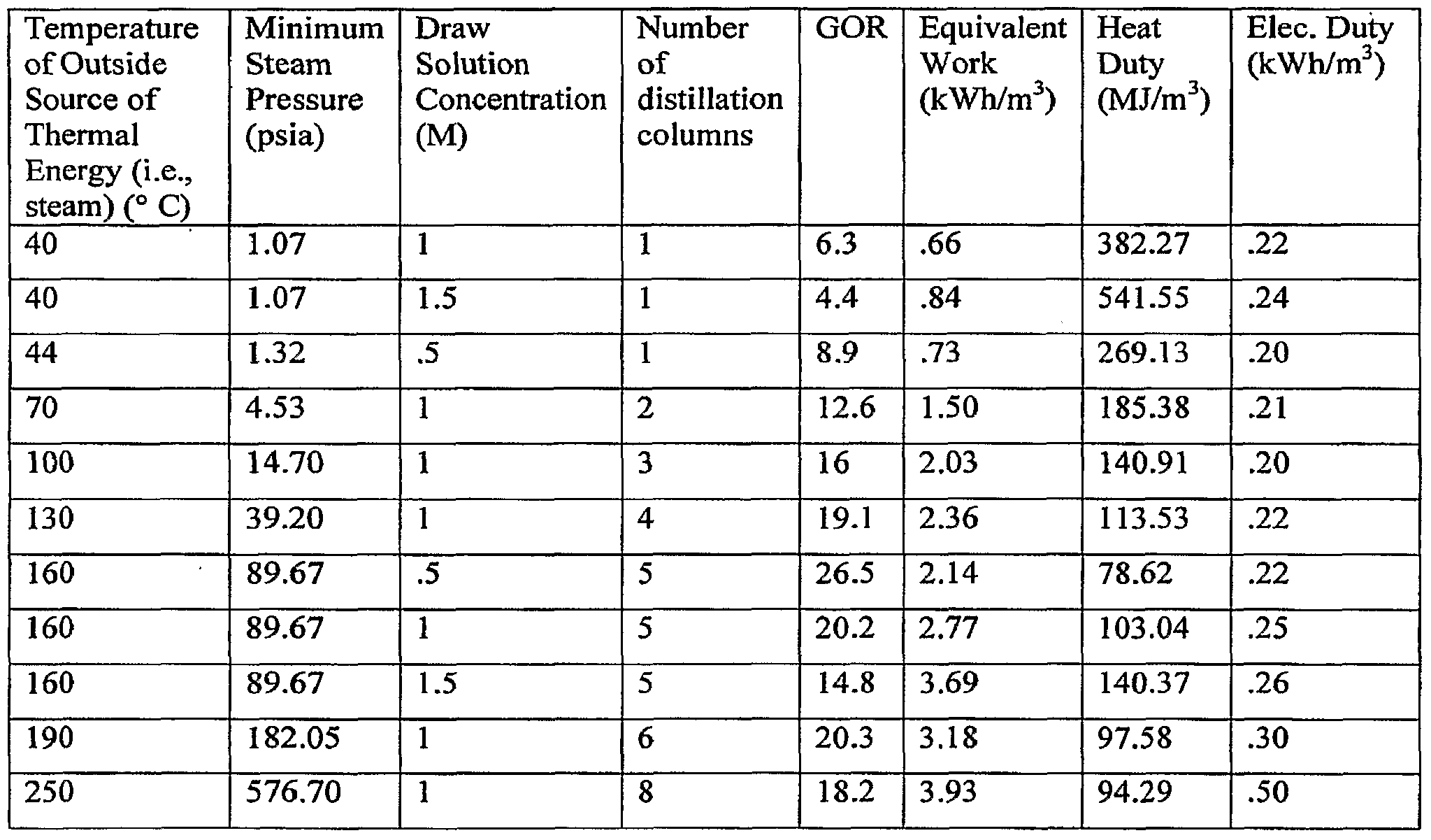
- Table 1 provides examples, indicating for a given temperature and minimum steam pressure of the outside thermal/heat energy source, concentration of the draw solution and an ambient temperature of 20° C, the optimum number of distillation columns for use in the separation of draw solution solutes and product solvent in accordance with the present invention.
- Table 1 is meant to be exemplary and not limiting.
- two distillation columns may be used with an outside thermal/heat energy source at a temperature of 50 0 C. It is further contemplated that draw solution concentrations of up to 6.0 molar can be used with the present invention. Furthermore, given a high enough temperature of the outside thermal/heat energy source and a sufficiently high efficiency target, up to at least about 15 distillation columns may be used in the practice of the present invention.
- the inventors have also considered the relationship between the temperature (also typically described as "quality") of the heat supplied to the FO recovery/separation system and the quantity of that energy required to separate draw solution solutes and product water from the draw solution.
- the unit of this relationship is in terms of gained output ratio (GOR), or the number of kilograms of water produced for each kilogram of steam condensed in the reboiler. This is a frequently used measure of the efficiency of thermal desalination systems, with higher numbers indicating higher efficiency.
- Figure 5 is a graphic representation of this relationship. Approximate typical values for MSF and MED are a GOR of between 8 and 15 at temperatures of 70 to 120° C.
- Table 2 provides the range of GOR values for a FO process using a single distillation column and the range of GOR values for the present invention utilizing a plurality of distillation columns. It is readily apparent that the present invention, with GOR values of between 14.2 and 29.7 for temperatures between 70 to 250° C has improved efficiency of heat use as compared with current desalination processes. The GOR is impacted by the temperature of the condensate stream returned to the external heat source.
- the examples provided herein are based on a condensate return stream at the same temperature as the steam provided as the heat energy source (i.e., both energy source (steam) and the water return stream is assumed to be at a temperature 200° C.) If the condensate return stream is returned at a lower temperature than the steam, the GOR increases, particularly at higher temperatures.
- the temperature of heat used by the FO process affects not only the quantity required, but also the value and therefore cost of the heat used.
- An effective method for estimating the value of process heat in thermal desalination systems involves the calculation of "equivalent work”. Using this method, thermal energy is assigned an electrical energy value, based on the capacity of that thermal energy to generate electricity in a steam turbine. If it is assumed that the steam used to supply thermal energy to a desalination process is extracted from a steam turbine, one may calculate the work that the steam could have done to generate electricity. This work value may be used for theoretical comparison of thermal process efficiencies, as well as for real-world costing of process steam supplied to a desalination process.
- the enthalpy of the steam at the point where it would normally enter the turbine condenser is subtracted from the enthalpy of the steam at the point where it is extracted and directed to the desalination process. This difference in enthalpy is multiplied by the efficiency of the turbine (in this instance assumed to be 95%) to assign the heat an equivalent work value, in kWh/kg steam.
- the amount of steam required to generate a cubic meter of water is given by the thermal process's GOR at that steam temperature.
- the result is multiplied by 1000 kg. of water to give a specific heat duty in terms of m 3 of water.
- the condenser temperature is assumed to be 35° C, based on tabular data relating condenser temperature to seawater cooling temperatures.
Abstract
Description


Claims
Priority Applications (10)
| Application Number | Priority Date | Filing Date | Title |
|---|---|---|---|
| AU2007258574A AU2007258574B2 (en) | 2006-06-08 | 2007-06-07 | Multi stage column distillation (MSCD) method for osmotic solute recovery |
| CN200780026027.6A CN101489937B (en) | 2006-06-08 | 2007-06-07 | Multi-stage column distillation (MSCD) method reclaimed for osmotic solute |
| KR1020087031971A KR101415627B1 (en) | 2006-06-08 | 2007-06-07 | Multi stage column distillation (mscd) method for osmotic solute recovery |
| US12/308,041 US8246791B2 (en) | 2006-06-08 | 2007-06-07 | Multi-stage column distillation (MSCD) method for osmotic solute recovery |
| CA2654508A CA2654508C (en) | 2006-06-08 | 2007-06-07 | Multi stage column distillation (mscd) method for osmotic solute recovery |
| MX2008015571A MX2008015571A (en) | 2006-06-08 | 2007-06-07 | Multi stage column distillation (mscd) method for osmotic solute recovery. |
| JP2009514384A JP5295952B2 (en) | 2006-06-08 | 2007-06-07 | Solute recovery system and recovery method for recovering osmotic solute |
| EP07795870A EP2035333A4 (en) | 2006-06-08 | 2007-06-07 | Multi stage column distillation (mscd) method for osmotic solute recovery |
| BRPI0712138-5A BRPI0712138A2 (en) | 2006-06-08 | 2007-06-07 | method for multistage column distillation (mscd) for osmotic solute recovery |
| IL195772A IL195772A (en) | 2006-06-08 | 2008-12-07 | Multi-stage column distillation (mscd) method for osmotic solute recovery |
Applications Claiming Priority (2)
| Application Number | Priority Date | Filing Date | Title |
|---|---|---|---|
| US81238306P | 2006-06-08 | 2006-06-08 | |
| US60/812,383 | 2006-06-08 |
Publications (3)
| Publication Number | Publication Date |
|---|---|
| WO2007146094A2 true WO2007146094A2 (en) | 2007-12-21 |
| WO2007146094A3 WO2007146094A3 (en) | 2008-02-07 |
| WO2007146094A8 WO2007146094A8 (en) | 2008-03-20 |
Family
ID=38832390
Family Applications (1)
| Application Number | Title | Priority Date | Filing Date |
|---|---|---|---|
| PCT/US2007/013463 WO2007146094A2 (en) | 2006-06-08 | 2007-06-07 | Multi stage column distillation (mscd) method for osmotic solute recovery |
Country Status (12)
| Country | Link |
|---|---|
| US (1) | US8246791B2 (en) |
| EP (1) | EP2035333A4 (en) |
| JP (1) | JP5295952B2 (en) |
| KR (1) | KR101415627B1 (en) |
| CN (1) | CN101489937B (en) |
| AU (1) | AU2007258574B2 (en) |
| BR (1) | BRPI0712138A2 (en) |
| CA (1) | CA2654508C (en) |
| IL (1) | IL195772A (en) |
| MX (1) | MX2008015571A (en) |
| SG (1) | SG172679A1 (en) |
| WO (1) | WO2007146094A2 (en) |
Cited By (11)
| Publication number | Priority date | Publication date | Assignee | Title |
|---|---|---|---|---|
| EP2303436A2 (en) * | 2008-06-20 | 2011-04-06 | Yale University | Forward osmosis separation processes |
| WO2011059751A2 (en) | 2009-10-28 | 2011-05-19 | Oasys Water, Inc. | Forward osmosis separation processes |
| JP2011115783A (en) * | 2009-10-30 | 2011-06-16 | Fujifilm Corp | Apparatus and method for purifying water |
| WO2012043669A1 (en) | 2010-09-29 | 2012-04-05 | 富士フイルム株式会社 | Forward osmosis device, and forward osmosis method |
| WO2012062392A1 (en) * | 2010-11-10 | 2012-05-18 | Aaa Water Technologies Ag | Forward osmosis system having solvent separation by means of membrane distillation |
| JP2013509298A (en) * | 2009-10-30 | 2013-03-14 | オアシス ウォーター,インコーポレーテッド | Osmotic separation system and method |
| US9044711B2 (en) | 2009-10-28 | 2015-06-02 | Oasys Water, Inc. | Osmotically driven membrane processes and systems and methods for draw solute recovery |
| US9707513B2 (en) | 2014-03-03 | 2017-07-18 | Blue Planet, Ltd. | Alkali enrichment mediated CO2 sequestration methods, and systems for practicing the same |
| US9993799B2 (en) | 2014-10-09 | 2018-06-12 | Blue Planet, Ltd. | Continuous carbon sequestration material production methods and systems for practicing the same |
| US10377647B2 (en) | 2010-12-15 | 2019-08-13 | Queen's University at Kingson | Systems and methods for use of water with switchable ionic strength |
| US11498853B2 (en) | 2010-02-10 | 2022-11-15 | Queen's University At Kingston | Water with switchable ionic strength |
Families Citing this family (39)
| Publication number | Priority date | Publication date | Assignee | Title |
|---|---|---|---|---|
| US9352281B2 (en) | 2001-02-01 | 2016-05-31 | Yale University | Forward osmosis separation processes |
| AU2002247049A1 (en) | 2001-02-01 | 2002-08-12 | Yale University | Osmotic desalination process |
| EP2501465A4 (en) * | 2009-06-08 | 2013-12-11 | Hydration Systems Llc | Osmotic pump for forward osmosis devices |
| US20110000861A1 (en) * | 2009-07-06 | 2011-01-06 | Bear Creek Services, LLC. | Portable and Scalable Water Reclamation System and Method |
| JP2011083663A (en) * | 2009-10-13 | 2011-04-28 | Fujifilm Corp | Water purification apparatus and method |
| US20110162952A1 (en) * | 2010-01-07 | 2011-07-07 | General Electric Company | Salt water desalination using energy from gasification process |
| CN101786768B (en) * | 2010-03-09 | 2011-11-23 | 天津工业大学 | Forward osmosis membrane bioreactor |
| WO2011163323A2 (en) | 2010-06-23 | 2011-12-29 | University Of Florida Research Foundation, Inc. | Modified carbonic anhydrase enzymes and their use in carbon dioxide sequestration and elimination |
| JP5943924B2 (en) * | 2010-09-22 | 2016-07-05 | オアシス ウォーター,インコーポレーテッド | Osmotic pressure driven membrane process and system, and extraction solute recovery method |
| AU2015255210B2 (en) * | 2010-09-22 | 2017-05-18 | Oasys Water LLC | Osmotically driven membrane processes and systems and methods for draw solute recovery |
| AU2012249903B2 (en) * | 2011-04-25 | 2015-11-12 | Oasys Water LLC | Osmotic separation systems and methods |
| PE20140821A1 (en) | 2011-08-10 | 2014-07-11 | Oasys Water Inc | MEMBRANE MODULES |
| JP2014526865A (en) * | 2011-09-07 | 2014-10-06 | オズモブルー・エスアーエールエル | Useful energy generating apparatus and method |
| JP5907340B2 (en) * | 2012-04-06 | 2016-04-26 | Jfeエンジニアリング株式会社 | Fresh water production apparatus and fresh water production method |
| WO2013065293A1 (en) * | 2011-10-31 | 2013-05-10 | Jfeエンジニアリング株式会社 | Method and device for preparing fresh water |
| JP5900745B2 (en) * | 2012-05-28 | 2016-04-06 | Jfeエンジニアリング株式会社 | Fresh water production method and fresh water production apparatus |
| JP5900743B2 (en) * | 2012-04-11 | 2016-04-06 | Jfeエンジニアリング株式会社 | Method and apparatus for treatment of associated water from a well |
| US20140124443A1 (en) * | 2012-11-07 | 2014-05-08 | Robert L. McGinnis | Systems and Methods for Integrated Heat Recovery in Thermally Separable Draw Solute Recycling in Osmotically Driven Membrane Processes |
| JP5988032B2 (en) * | 2012-11-13 | 2016-09-07 | Jfeエンジニアリング株式会社 | Fresh water production apparatus and operation method thereof |
| JP5910466B2 (en) * | 2012-11-15 | 2016-04-27 | Jfeエンジニアリング株式会社 | Water purification manufacturing method and apparatus |
| MX2015006147A (en) * | 2012-11-16 | 2015-08-05 | Oasys Water Inc | Draw solutions and draw solute recovery for osmotically driven membrane processes. |
| CN104955552B (en) | 2012-12-21 | 2017-03-08 | 波里费拉公司 | For carrying out detached piece-rate system, element and method using stacking barrier film and distance piece |
| KR101454314B1 (en) * | 2013-02-04 | 2014-10-27 | 한국기계연구원 | Draw solution recovering method for forward osmosis system |
| US9546426B2 (en) | 2013-03-07 | 2017-01-17 | The Penn State Research Foundation | Methods for hydrogen gas production |
| US20140262729A1 (en) * | 2013-03-14 | 2014-09-18 | Elwha Llc | Heat transfer between a distillation column and a temperature source |
| US9861937B2 (en) | 2013-03-15 | 2018-01-09 | Porifera, Inc. | Advancements in osmotically driven membrane systems including low pressure control |
| CN105229119B (en) * | 2013-08-01 | 2017-03-08 | Lg化学株式会社 | Purifier apparatus and the purification process using this purifier apparatus |
| CN103819040B (en) * | 2014-02-25 | 2015-04-29 | 张英华 | Forward-osmosis industrial sewage treatment equipment and technical process thereof |
| US9206061B1 (en) * | 2014-08-06 | 2015-12-08 | James Jeffrey Harris | Alternating osmotic pressure from a metal salt osmolyte to enhance forward osmosis processes |
| CN104386871B (en) * | 2014-11-28 | 2016-07-27 | 马涛 | A kind of energy-saving sewage factory secondary biochemical effluent desalting system and processing method thereof |
| US20170369337A1 (en) * | 2014-12-23 | 2017-12-28 | Oasys Water, Inc. | Enhanced brine concentration with osmotically driven membrane systems and processes |
| PL3313786T3 (en) | 2015-06-24 | 2020-11-02 | Porifera, Inc. | Methods of dewatering of alcoholic solutions via forward osmosis and related systems |
| CN107810044B (en) * | 2015-07-01 | 2021-05-25 | 科思创德国股份有限公司 | Osmotic distillation process for concentrating sodium chloride-containing liquids |
| US9604178B1 (en) | 2016-04-17 | 2017-03-28 | Upen Jayant BHARWADA | Integrated osmosis systems and methods |
| KR102190050B1 (en) * | 2016-08-04 | 2020-12-14 | 오아시스 워터 엘엘씨 | System and method for improving the performance of forward osmosis system |
| WO2018119460A1 (en) | 2016-12-23 | 2018-06-28 | Porifera, Inc. | Removing components of alcoholic solutions via forward osmosis and related systems |
| US20210268438A1 (en) | 2018-07-19 | 2021-09-02 | Maruzen Petrochemical Co., Ltd. | Draw solute, draw solution, and forward-osmosis water treatment method |
| GB202002089D0 (en) | 2020-02-14 | 2020-04-01 | Waterwhelm Ltd | Apparatus and method for liquid treatment by forward osmosis |
| EP3865204A1 (en) * | 2020-02-14 | 2021-08-18 | Waterwhelm Ltd | Apparatus and method for liquid treatment by forward osmosis |
Citations (2)
| Publication number | Priority date | Publication date | Assignee | Title |
|---|---|---|---|---|
| EP1452219A1 (en) | 2001-10-19 | 2004-09-01 | Bio Nanotec Research Institure, Inc. | Water-soluble organic material condensation apparatus |
| US20050045568A1 (en) | 2003-09-03 | 2005-03-03 | Laing David A. | High debris content strainer |
Family Cites Families (16)
| Publication number | Priority date | Publication date | Assignee | Title |
|---|---|---|---|---|
| US4111759A (en) * | 1976-07-08 | 1978-09-05 | United States Steel Corporation | Process for separating ammonia and acid gases from waste waters containing fixed ammonia salts |
| KR800001159B1 (en) * | 1977-11-02 | 1980-10-18 | 제이. 엠. 제이. 쟌쎈하. 베. 반리우벤 | Process of separating substantially pure nh3 and substantially pure co2 from a composition containing nh3 and co2 |
| US4539076A (en) * | 1982-09-27 | 1985-09-03 | Swain R L Bibb | Vapor compression distillation system |
| US5124004A (en) * | 1983-08-22 | 1992-06-23 | Trustees Of Dartmouth College | Distillation process for ethanol |
| SE503351C2 (en) * | 1994-09-06 | 1996-05-28 | Ahlstroem Oy | Process for the purification of secondary condensates in evaporation of liquor |
| JPH08318136A (en) * | 1995-05-25 | 1996-12-03 | Sumitomo Heavy Ind Ltd | Seawater desalting and salt manufacturing method |
| US6551466B1 (en) | 1998-01-14 | 2003-04-22 | Aqua Pure Ventures Inc. | Multiple effect distillation process with reduced fouling |
| WO1999039799A1 (en) | 1998-02-09 | 1999-08-12 | Mcginnis Robert L | Osmotic desalinization process |
| US6783682B1 (en) * | 1999-08-20 | 2004-08-31 | L.E.T., Leading Edge Technologies Limited | Salt water desalination process using ion selective membranes |
| JP2002102844A (en) | 2000-09-29 | 2002-04-09 | Nippon Kentetsu Co Ltd | Apparatus for converting seawater into fresh water |
| AU2002247049A1 (en) * | 2001-02-01 | 2002-08-12 | Yale University | Osmotic desalination process |
| EP1608448A4 (en) * | 2003-03-28 | 2007-10-24 | Thermal Kinetics Systems Llc | Ethanol distillation with distillers soluble solids recovery apparatus |
| GB0319042D0 (en) * | 2003-08-13 | 2003-09-17 | Univ Surrey | Osmotic energy |
| MXPA06009074A (en) | 2004-02-10 | 2007-03-21 | Texas A & M Univ Sys | Vapor-compression evaporation system and method. |
| US7799178B2 (en) * | 2005-01-07 | 2010-09-21 | Black & Veatch Holding Company | Distillation process |
| JP2009500318A (en) * | 2005-06-29 | 2009-01-08 | パナセア バイオテック リミテッド | Novel sustained-release pharmaceutical composition and production method thereof |
-
2007
- 2007-06-07 AU AU2007258574A patent/AU2007258574B2/en not_active Ceased
- 2007-06-07 BR BRPI0712138-5A patent/BRPI0712138A2/en not_active Application Discontinuation
- 2007-06-07 MX MX2008015571A patent/MX2008015571A/en active IP Right Grant
- 2007-06-07 SG SG2011041019A patent/SG172679A1/en unknown
- 2007-06-07 WO PCT/US2007/013463 patent/WO2007146094A2/en active Application Filing
- 2007-06-07 JP JP2009514384A patent/JP5295952B2/en not_active Expired - Fee Related
- 2007-06-07 CN CN200780026027.6A patent/CN101489937B/en active Active
- 2007-06-07 CA CA2654508A patent/CA2654508C/en active Active
- 2007-06-07 KR KR1020087031971A patent/KR101415627B1/en active IP Right Grant
- 2007-06-07 EP EP07795870A patent/EP2035333A4/en not_active Withdrawn
- 2007-06-07 US US12/308,041 patent/US8246791B2/en active Active
-
2008
- 2008-12-07 IL IL195772A patent/IL195772A/en active IP Right Grant
Patent Citations (2)
| Publication number | Priority date | Publication date | Assignee | Title |
|---|---|---|---|---|
| EP1452219A1 (en) | 2001-10-19 | 2004-09-01 | Bio Nanotec Research Institure, Inc. | Water-soluble organic material condensation apparatus |
| US20050045568A1 (en) | 2003-09-03 | 2005-03-03 | Laing David A. | High debris content strainer |
Non-Patent Citations (1)
| Title |
|---|
| See also references of EP2035333A4 |
Cited By (32)
| Publication number | Priority date | Publication date | Assignee | Title |
|---|---|---|---|---|
| AU2009259824B2 (en) * | 2008-06-20 | 2015-07-09 | Yale University | Forward osmosis separation processes |
| EP2303436A2 (en) * | 2008-06-20 | 2011-04-06 | Yale University | Forward osmosis separation processes |
| EP2303436A4 (en) * | 2008-06-20 | 2012-08-15 | Univ Yale | Forward osmosis separation processes |
| WO2011059751A2 (en) | 2009-10-28 | 2011-05-19 | Oasys Water, Inc. | Forward osmosis separation processes |
| EP2493596A4 (en) * | 2009-10-28 | 2016-08-03 | Oasys Water Inc | Forward osmosis separation processes |
| US10315936B2 (en) | 2009-10-28 | 2019-06-11 | Oasys Water LLC | Forward osmosis separation processes |
| CN102725053A (en) * | 2009-10-28 | 2012-10-10 | Oasys水有限公司 | Forward osmosis separation processes |
| US9248405B2 (en) | 2009-10-28 | 2016-02-02 | Oasys Water, Inc. | Forward osmosis separation processes |
| AU2010319846B2 (en) * | 2009-10-28 | 2015-05-28 | Oasys Water LLC | Forward osmosis separation processes |
| US9044711B2 (en) | 2009-10-28 | 2015-06-02 | Oasys Water, Inc. | Osmotically driven membrane processes and systems and methods for draw solute recovery |
| US10315163B2 (en) | 2009-10-30 | 2019-06-11 | Oasys Water LLC | Osmotic separation systems and methods |
| JP2013509298A (en) * | 2009-10-30 | 2013-03-14 | オアシス ウォーター,インコーポレーテッド | Osmotic separation system and method |
| US9266065B2 (en) | 2009-10-30 | 2016-02-23 | Oasys Water, Inc. | Osmotic separation systems and methods |
| JP2016104483A (en) * | 2009-10-30 | 2016-06-09 | オアシス ウォーター,インコーポレーテッド | Infiltration separation system and method |
| EP2493595A4 (en) * | 2009-10-30 | 2016-08-03 | Oasys Water Inc | Osmotic separation systems and methods |
| JP2011115783A (en) * | 2009-10-30 | 2011-06-16 | Fujifilm Corp | Apparatus and method for purifying water |
| US11498853B2 (en) | 2010-02-10 | 2022-11-15 | Queen's University At Kingston | Water with switchable ionic strength |
| US9630861B2 (en) | 2010-09-29 | 2017-04-25 | Fujifilm Corporation | Forward osmosis apparatus and forward osmosis process |
| US10703652B2 (en) | 2010-09-29 | 2020-07-07 | Fujifilm Corporation | Forward osmosis process |
| WO2012043669A1 (en) | 2010-09-29 | 2012-04-05 | 富士フイルム株式会社 | Forward osmosis device, and forward osmosis method |
| US10087089B2 (en) | 2010-09-29 | 2018-10-02 | Fujifilm Corporation | Draw solution for forward osmosis process |
| US10087090B2 (en) | 2010-09-29 | 2018-10-02 | Fujifilm Corporation | Forward osmosis process |
| US9656883B2 (en) | 2010-11-10 | 2017-05-23 | Aaa Water Technologies Ag | Forward osmosis system comprising solvent separation by means of membrane distillation |
| WO2012062392A1 (en) * | 2010-11-10 | 2012-05-18 | Aaa Water Technologies Ag | Forward osmosis system having solvent separation by means of membrane distillation |
| US10377647B2 (en) | 2010-12-15 | 2019-08-13 | Queen's University at Kingson | Systems and methods for use of water with switchable ionic strength |
| US9707513B2 (en) | 2014-03-03 | 2017-07-18 | Blue Planet, Ltd. | Alkali enrichment mediated CO2 sequestration methods, and systems for practicing the same |
| US10898854B2 (en) | 2014-03-03 | 2021-01-26 | Blue Planet Systems Corporation | Alkali enrichment mediated CO2 sequestration methods, and systems for practicing the same |
| US11577198B2 (en) | 2014-03-03 | 2023-02-14 | Blue Planet Systems Corporation | Alkali enrichment mediated CO2 sequestration methods, and systems for practicing the same |
| US10766015B2 (en) | 2014-10-09 | 2020-09-08 | Blue Planet, Ltd. | Continuous carbon sequestration material production methods and systems for practicing the same |
| US11344861B2 (en) | 2014-10-09 | 2022-05-31 | Blue Planet Systems Corporation | Continuous carbon sequestration material production methods and systems for practicing the same |
| US9993799B2 (en) | 2014-10-09 | 2018-06-12 | Blue Planet, Ltd. | Continuous carbon sequestration material production methods and systems for practicing the same |
| US11938458B2 (en) | 2014-10-09 | 2024-03-26 | Blue Planet Systems Corporation | Continuous carbon sequestration material production methods and systems for practicing the same |
Also Published As
| Publication number | Publication date |
|---|---|
| AU2007258574A2 (en) | 2010-02-18 |
| JP2009539584A (en) | 2009-11-19 |
| AU2007258574B2 (en) | 2012-02-02 |
| BRPI0712138A2 (en) | 2012-01-10 |
| EP2035333A2 (en) | 2009-03-18 |
| KR20090029232A (en) | 2009-03-20 |
| SG172679A1 (en) | 2011-07-28 |
| US20090297431A1 (en) | 2009-12-03 |
| US8246791B2 (en) | 2012-08-21 |
| IL195772A (en) | 2014-03-31 |
| KR101415627B1 (en) | 2014-07-11 |
| WO2007146094A3 (en) | 2008-02-07 |
| CN101489937B (en) | 2016-08-10 |
| CN101489937A (en) | 2009-07-22 |
| MX2008015571A (en) | 2009-04-24 |
| EP2035333A4 (en) | 2011-01-05 |
| IL195772A0 (en) | 2009-09-01 |
| JP5295952B2 (en) | 2013-09-18 |
| WO2007146094A8 (en) | 2008-03-20 |
| AU2007258574A1 (en) | 2007-12-21 |
| CA2654508A1 (en) | 2007-12-21 |
| CA2654508C (en) | 2014-07-29 |
Similar Documents
| Publication | Publication Date | Title |
|---|---|---|
| CA2654508C (en) | Multi stage column distillation (mscd) method for osmotic solute recovery | |
| McGinnis et al. | Energy requirements of ammonia–carbon dioxide forward osmosis desalination | |
| JP2009539584A6 (en) | Multistage column distillation (MSCD) method for recovering osmotic solutes | |
| US9044711B2 (en) | Osmotically driven membrane processes and systems and methods for draw solute recovery | |
| CN107970627B (en) | Multi-stage bubble column humidifier | |
| CA2778537C (en) | Forward osmosis separation processes | |
| Vane | Water recovery from brines and salt‐saturated solutions: operability and thermodynamic efficiency considerations for desalination technologies | |
| JP5943924B2 (en) | Osmotic pressure driven membrane process and system, and extraction solute recovery method | |
| US20170361277A1 (en) | Vacuumed gap membrane distillation (vagmed) module, multi-stage vagmed systems, and vagmed processes | |
| US20140124443A1 (en) | Systems and Methods for Integrated Heat Recovery in Thermally Separable Draw Solute Recycling in Osmotically Driven Membrane Processes | |
| JP2007275690A (en) | Method for separating and recovering organic liquid from organic liquid aqueous solution | |
| US11261111B2 (en) | Methods and systems for treating an aqueous solution | |
| EP2708276A1 (en) | Improved membrane gas desorption | |
| AU2015255210A1 (en) | Osmotically driven membrane processes and systems and methods for draw solute recovery | |
| Chudnovsky et al. | Integrated Wastewater Recovery and Reuse via Waste Heat Utilization |
Legal Events
| Date | Code | Title | Description |
|---|---|---|---|
| WWE | Wipo information: entry into national phase |
Ref document number: 200780026027.6 Country of ref document: CN |
|
| 121 | Ep: the epo has been informed by wipo that ep was designated in this application |
Ref document number: 07795870 Country of ref document: EP Kind code of ref document: A2 |
|
| ENP | Entry into the national phase |
Ref document number: 2654508 Country of ref document: CA |
|
| WWE | Wipo information: entry into national phase |
Ref document number: 12308041 Country of ref document: US Ref document number: 2009514384 Country of ref document: JP Ref document number: MX/A/2008/015571 Country of ref document: MX |
|
| WWE | Wipo information: entry into national phase |
Ref document number: 195772 Country of ref document: IL |
|
| WWE | Wipo information: entry into national phase |
Ref document number: 2007258574 Country of ref document: AU Ref document number: 5040/KOLNP/2008 Country of ref document: IN |
|
| WWE | Wipo information: entry into national phase |
Ref document number: 1020087031971 Country of ref document: KR |
|
| REEP | Request for entry into the european phase |
Ref document number: 2007795870 Country of ref document: EP |
|
| WWE | Wipo information: entry into national phase |
Ref document number: 2007795870 Country of ref document: EP |
|
| ENP | Entry into the national phase |
Ref document number: 2007258574 Country of ref document: AU Date of ref document: 20070607 Kind code of ref document: A |
|
| NENP | Non-entry into the national phase |
Ref country code: RU |
|
| ENP | Entry into the national phase |
Ref document number: PI0712138 Country of ref document: BR Kind code of ref document: A2 Effective date: 20081208 |