WO2009029466A1 - Vehicle transparency - Google Patents
Vehicle transparency Download PDFInfo
- Publication number
- WO2009029466A1 WO2009029466A1 PCT/US2008/073803 US2008073803W WO2009029466A1 WO 2009029466 A1 WO2009029466 A1 WO 2009029466A1 US 2008073803 W US2008073803 W US 2008073803W WO 2009029466 A1 WO2009029466 A1 WO 2009029466A1
- Authority
- WO
- WIPO (PCT)
- Prior art keywords
- layer
- ply
- thickness
- range
- coating
- Prior art date
Links
- 238000000576 coating method Methods 0.000 claims abstract description 84
- 239000011248 coating agent Substances 0.000 claims abstract description 77
- 230000005540 biological transmission Effects 0.000 claims abstract description 48
- XLOMVQKBTHCTTD-UHFFFAOYSA-N Zinc monoxide Chemical compound [Zn]=O XLOMVQKBTHCTTD-UHFFFAOYSA-N 0.000 claims description 105
- 239000011521 glass Substances 0.000 claims description 56
- 239000011787 zinc oxide Substances 0.000 claims description 52
- BQCADISMDOOEFD-UHFFFAOYSA-N Silver Chemical compound [Ag] BQCADISMDOOEFD-UHFFFAOYSA-N 0.000 claims description 43
- 229910052709 silver Inorganic materials 0.000 claims description 43
- 239000004332 silver Substances 0.000 claims description 43
- 239000000463 material Substances 0.000 claims description 42
- BNEMLSQAJOPTGK-UHFFFAOYSA-N zinc;dioxido(oxo)tin Chemical compound [Zn+2].[O-][Sn]([O-])=O BNEMLSQAJOPTGK-UHFFFAOYSA-N 0.000 claims description 40
- 239000000758 substrate Substances 0.000 claims description 16
- 239000006117 anti-reflective coating Substances 0.000 claims description 14
- 239000005347 annealed glass Substances 0.000 claims description 3
- 239000010410 layer Substances 0.000 description 201
- VYPSYNLAJGMNEJ-UHFFFAOYSA-N Silicium dioxide Chemical compound O=[Si]=O VYPSYNLAJGMNEJ-UHFFFAOYSA-N 0.000 description 80
- PNEYBMLMFCGWSK-UHFFFAOYSA-N aluminium oxide Inorganic materials [O-2].[O-2].[O-2].[Al+3].[Al+3] PNEYBMLMFCGWSK-UHFFFAOYSA-N 0.000 description 42
- 239000000377 silicon dioxide Substances 0.000 description 40
- 239000000203 mixture Substances 0.000 description 27
- 150000004706 metal oxides Chemical class 0.000 description 25
- 229910044991 metal oxide Inorganic materials 0.000 description 24
- RTAQQCXQSZGOHL-UHFFFAOYSA-N Titanium Chemical compound [Ti] RTAQQCXQSZGOHL-UHFFFAOYSA-N 0.000 description 21
- 239000010936 titanium Substances 0.000 description 21
- 229910052719 titanium Inorganic materials 0.000 description 21
- 239000011701 zinc Substances 0.000 description 21
- HCHKCACWOHOZIP-UHFFFAOYSA-N Zinc Chemical compound [Zn] HCHKCACWOHOZIP-UHFFFAOYSA-N 0.000 description 20
- 230000003287 optical effect Effects 0.000 description 19
- 239000011253 protective coating Substances 0.000 description 18
- 229910001092 metal group alloy Inorganic materials 0.000 description 17
- 229910052725 zinc Inorganic materials 0.000 description 17
- ATJFFYVFTNAWJD-UHFFFAOYSA-N Tin Chemical compound [Sn] ATJFFYVFTNAWJD-UHFFFAOYSA-N 0.000 description 14
- 229910052751 metal Inorganic materials 0.000 description 14
- 239000002184 metal Substances 0.000 description 14
- 239000000853 adhesive Substances 0.000 description 13
- 230000001070 adhesive effect Effects 0.000 description 13
- 239000011229 interlayer Substances 0.000 description 11
- 230000005855 radiation Effects 0.000 description 10
- -1 e.g. Polymers 0.000 description 9
- 239000011247 coating layer Substances 0.000 description 8
- 230000001681 protective effect Effects 0.000 description 8
- 238000000034 method Methods 0.000 description 7
- GWEVSGVZZGPLCZ-UHFFFAOYSA-N Titan oxide Chemical compound O=[Ti]=O GWEVSGVZZGPLCZ-UHFFFAOYSA-N 0.000 description 6
- MCMNRKCIXSYSNV-UHFFFAOYSA-N Zirconium dioxide Chemical compound O=[Zr]=O MCMNRKCIXSYSNV-UHFFFAOYSA-N 0.000 description 6
- 229910045601 alloy Inorganic materials 0.000 description 6
- 239000000956 alloy Substances 0.000 description 6
- 229920002037 poly(vinyl butyral) polymer Polymers 0.000 description 6
- 238000012545 processing Methods 0.000 description 6
- 239000010703 silicon Substances 0.000 description 6
- 229910052710 silicon Inorganic materials 0.000 description 6
- 229910001887 tin oxide Inorganic materials 0.000 description 6
- 229910052782 aluminium Inorganic materials 0.000 description 5
- PXHVJJICTQNCMI-UHFFFAOYSA-N Nickel Chemical compound [Ni] PXHVJJICTQNCMI-UHFFFAOYSA-N 0.000 description 4
- XUIMIQQOPSSXEZ-UHFFFAOYSA-N Silicon Chemical compound [Si] XUIMIQQOPSSXEZ-UHFFFAOYSA-N 0.000 description 4
- 229910001128 Sn alloy Inorganic materials 0.000 description 4
- 229910003107 Zn2SnO4 Inorganic materials 0.000 description 4
- XAGFODPZIPBFFR-UHFFFAOYSA-N aluminium Chemical compound [Al] XAGFODPZIPBFFR-UHFFFAOYSA-N 0.000 description 4
- 239000005329 float glass Substances 0.000 description 4
- 229920000642 polymer Polymers 0.000 description 4
- 238000004544 sputter deposition Methods 0.000 description 4
- XOLBLPGZBRYERU-UHFFFAOYSA-N tin dioxide Chemical compound O=[Sn]=O XOLBLPGZBRYERU-UHFFFAOYSA-N 0.000 description 4
- 238000002834 transmittance Methods 0.000 description 4
- 229910001297 Zn alloy Inorganic materials 0.000 description 3
- 230000003667 anti-reflective effect Effects 0.000 description 3
- 238000005229 chemical vapour deposition Methods 0.000 description 3
- 150000004767 nitrides Chemical class 0.000 description 3
- 238000005240 physical vapour deposition Methods 0.000 description 3
- 229920000139 polyethylene terephthalate Polymers 0.000 description 3
- 239000005020 polyethylene terephthalate Substances 0.000 description 3
- ZOXJGFHDIHLPTG-UHFFFAOYSA-N Boron Chemical compound [B] ZOXJGFHDIHLPTG-UHFFFAOYSA-N 0.000 description 2
- RYGMFSIKBFXOCR-UHFFFAOYSA-N Copper Chemical compound [Cu] RYGMFSIKBFXOCR-UHFFFAOYSA-N 0.000 description 2
- 238000006124 Pilkington process Methods 0.000 description 2
- 238000003848 UV Light-Curing Methods 0.000 description 2
- QCWXUUIWCKQGHC-UHFFFAOYSA-N Zirconium Chemical compound [Zr] QCWXUUIWCKQGHC-UHFFFAOYSA-N 0.000 description 2
- QVGXLLKOCUKJST-UHFFFAOYSA-N atomic oxygen Chemical compound [O] QVGXLLKOCUKJST-UHFFFAOYSA-N 0.000 description 2
- 230000004888 barrier function Effects 0.000 description 2
- 229910052796 boron Inorganic materials 0.000 description 2
- 238000007796 conventional method Methods 0.000 description 2
- 229920001577 copolymer Polymers 0.000 description 2
- 239000010949 copper Substances 0.000 description 2
- 229910052802 copper Inorganic materials 0.000 description 2
- 230000007423 decrease Effects 0.000 description 2
- 230000005670 electromagnetic radiation Effects 0.000 description 2
- PCHJSUWPFVWCPO-UHFFFAOYSA-N gold Chemical compound [Au] PCHJSUWPFVWCPO-UHFFFAOYSA-N 0.000 description 2
- 229910052737 gold Inorganic materials 0.000 description 2
- 239000010931 gold Substances 0.000 description 2
- 229910052735 hafnium Inorganic materials 0.000 description 2
- VBJZVLUMGGDVMO-UHFFFAOYSA-N hafnium atom Chemical compound [Hf] VBJZVLUMGGDVMO-UHFFFAOYSA-N 0.000 description 2
- 238000010438 heat treatment Methods 0.000 description 2
- 229910052738 indium Inorganic materials 0.000 description 2
- APFVFJFRJDLVQX-UHFFFAOYSA-N indium atom Chemical compound [In] APFVFJFRJDLVQX-UHFFFAOYSA-N 0.000 description 2
- 239000000178 monomer Substances 0.000 description 2
- 229910052759 nickel Inorganic materials 0.000 description 2
- 229910052755 nonmetal Inorganic materials 0.000 description 2
- 230000003647 oxidation Effects 0.000 description 2
- 238000007254 oxidation reaction Methods 0.000 description 2
- TWNQGVIAIRXVLR-UHFFFAOYSA-N oxo(oxoalumanyloxy)alumane Chemical compound O=[Al]O[Al]=O TWNQGVIAIRXVLR-UHFFFAOYSA-N 0.000 description 2
- 229910052760 oxygen Inorganic materials 0.000 description 2
- 239000001301 oxygen Substances 0.000 description 2
- 229920003023 plastic Polymers 0.000 description 2
- 239000004033 plastic Substances 0.000 description 2
- 229920000058 polyacrylate Polymers 0.000 description 2
- 239000002356 single layer Substances 0.000 description 2
- 238000001228 spectrum Methods 0.000 description 2
- 239000000126 substance Substances 0.000 description 2
- 238000012360 testing method Methods 0.000 description 2
- QHGNHLZPVBIIPX-UHFFFAOYSA-N tin(ii) oxide Chemical class [Sn]=O QHGNHLZPVBIIPX-UHFFFAOYSA-N 0.000 description 2
- XLYOFNOQVPJJNP-UHFFFAOYSA-N water Substances O XLYOFNOQVPJJNP-UHFFFAOYSA-N 0.000 description 2
- 229910052726 zirconium Inorganic materials 0.000 description 2
- VYZAMTAEIAYCRO-UHFFFAOYSA-N Chromium Chemical compound [Cr] VYZAMTAEIAYCRO-UHFFFAOYSA-N 0.000 description 1
- PWHULOQIROXLJO-UHFFFAOYSA-N Manganese Chemical compound [Mn] PWHULOQIROXLJO-UHFFFAOYSA-N 0.000 description 1
- 229920012485 Plasticized Polyvinyl chloride Polymers 0.000 description 1
- 238000010521 absorption reaction Methods 0.000 description 1
- 239000012790 adhesive layer Substances 0.000 description 1
- 238000004378 air conditioning Methods 0.000 description 1
- 229910052787 antimony Inorganic materials 0.000 description 1
- WATWJIUSRGPENY-UHFFFAOYSA-N antimony atom Chemical compound [Sb] WATWJIUSRGPENY-UHFFFAOYSA-N 0.000 description 1
- 238000005452 bending Methods 0.000 description 1
- 229910052797 bismuth Inorganic materials 0.000 description 1
- JCXGWMGPZLAOME-UHFFFAOYSA-N bismuth atom Chemical compound [Bi] JCXGWMGPZLAOME-UHFFFAOYSA-N 0.000 description 1
- 229910000416 bismuth oxide Inorganic materials 0.000 description 1
- 239000005388 borosilicate glass Substances 0.000 description 1
- 230000015556 catabolic process Effects 0.000 description 1
- 239000000919 ceramic Substances 0.000 description 1
- 238000006243 chemical reaction Methods 0.000 description 1
- 229910052804 chromium Inorganic materials 0.000 description 1
- 239000011651 chromium Substances 0.000 description 1
- 239000008199 coating composition Substances 0.000 description 1
- 150000001875 compounds Chemical class 0.000 description 1
- 238000001723 curing Methods 0.000 description 1
- 238000006731 degradation reaction Methods 0.000 description 1
- 238000000151 deposition Methods 0.000 description 1
- 230000008021 deposition Effects 0.000 description 1
- 238000005137 deposition process Methods 0.000 description 1
- TYIXMATWDRGMPF-UHFFFAOYSA-N dibismuth;oxygen(2-) Chemical compound [O-2].[O-2].[O-2].[Bi+3].[Bi+3] TYIXMATWDRGMPF-UHFFFAOYSA-N 0.000 description 1
- 239000003989 dielectric material Substances 0.000 description 1
- 238000005566 electron beam evaporation Methods 0.000 description 1
- 230000005284 excitation Effects 0.000 description 1
- 239000000446 fuel Substances 0.000 description 1
- 229920001519 homopolymer Polymers 0.000 description 1
- BHEPBYXIRTUNPN-UHFFFAOYSA-N hydridophosphorus(.) (triplet) Chemical compound [PH] BHEPBYXIRTUNPN-UHFFFAOYSA-N 0.000 description 1
- 229910003437 indium oxide Inorganic materials 0.000 description 1
- RHZWSUVWRRXEJF-UHFFFAOYSA-N indium tin Chemical compound [In].[Sn] RHZWSUVWRRXEJF-UHFFFAOYSA-N 0.000 description 1
- PJXISJQVUVHSOJ-UHFFFAOYSA-N indium(iii) oxide Chemical compound [O-2].[O-2].[O-2].[In+3].[In+3] PJXISJQVUVHSOJ-UHFFFAOYSA-N 0.000 description 1
- 239000004615 ingredient Substances 0.000 description 1
- 239000007788 liquid Substances 0.000 description 1
- 238000001755 magnetron sputter deposition Methods 0.000 description 1
- 229910052748 manganese Inorganic materials 0.000 description 1
- 239000011572 manganese Substances 0.000 description 1
- 150000002739 metals Chemical class 0.000 description 1
- 238000012986 modification Methods 0.000 description 1
- 230000004048 modification Effects 0.000 description 1
- 239000006060 molten glass Substances 0.000 description 1
- 230000007935 neutral effect Effects 0.000 description 1
- 229910052758 niobium Inorganic materials 0.000 description 1
- 239000010955 niobium Substances 0.000 description 1
- GUCVJGMIXFAOAE-UHFFFAOYSA-N niobium atom Chemical compound [Nb] GUCVJGMIXFAOAE-UHFFFAOYSA-N 0.000 description 1
- 229910000510 noble metal Inorganic materials 0.000 description 1
- 150000002843 nonmetals Chemical class 0.000 description 1
- 230000000704 physical effect Effects 0.000 description 1
- 229920001483 poly(ethyl methacrylate) polymer Polymers 0.000 description 1
- 229920003229 poly(methyl methacrylate) Polymers 0.000 description 1
- 229920001707 polybutylene terephthalate Polymers 0.000 description 1
- 229920000515 polycarbonate Polymers 0.000 description 1
- 239000004417 polycarbonate Substances 0.000 description 1
- 239000013047 polymeric layer Substances 0.000 description 1
- 229920001296 polysiloxane Polymers 0.000 description 1
- 229920002635 polyurethane Polymers 0.000 description 1
- 239000004814 polyurethane Substances 0.000 description 1
- 239000004065 semiconductor Substances 0.000 description 1
- 239000005368 silicate glass Substances 0.000 description 1
- 150000003376 silicon Chemical class 0.000 description 1
- LIVNPJMFVYWSIS-UHFFFAOYSA-N silicon monoxide Chemical class [Si-]#[O+] LIVNPJMFVYWSIS-UHFFFAOYSA-N 0.000 description 1
- 229910052814 silicon oxide Inorganic materials 0.000 description 1
- 238000005118 spray pyrolysis Methods 0.000 description 1
- 229920001897 terpolymer Polymers 0.000 description 1
- 239000012815 thermoplastic material Substances 0.000 description 1
- 239000004408 titanium dioxide Substances 0.000 description 1
- 238000012546 transfer Methods 0.000 description 1
- 238000001771 vacuum deposition Methods 0.000 description 1
- 238000007740 vapor deposition Methods 0.000 description 1
- 238000001429 visible spectrum Methods 0.000 description 1
- 229910052727 yttrium Inorganic materials 0.000 description 1
- VWQVUPCCIRVNHF-UHFFFAOYSA-N yttrium atom Chemical compound [Y] VWQVUPCCIRVNHF-UHFFFAOYSA-N 0.000 description 1
Classifications
-
- B—PERFORMING OPERATIONS; TRANSPORTING
- B32—LAYERED PRODUCTS
- B32B—LAYERED PRODUCTS, i.e. PRODUCTS BUILT-UP OF STRATA OF FLAT OR NON-FLAT, e.g. CELLULAR OR HONEYCOMB, FORM
- B32B17/00—Layered products essentially comprising sheet glass, or glass, slag, or like fibres
- B32B17/06—Layered products essentially comprising sheet glass, or glass, slag, or like fibres comprising glass as the main or only constituent of a layer, next to another layer of a specific material
- B32B17/10—Layered products essentially comprising sheet glass, or glass, slag, or like fibres comprising glass as the main or only constituent of a layer, next to another layer of a specific material of synthetic resin
- B32B17/10005—Layered products essentially comprising sheet glass, or glass, slag, or like fibres comprising glass as the main or only constituent of a layer, next to another layer of a specific material of synthetic resin laminated safety glass or glazing
- B32B17/10009—Layered products essentially comprising sheet glass, or glass, slag, or like fibres comprising glass as the main or only constituent of a layer, next to another layer of a specific material of synthetic resin laminated safety glass or glazing characterized by the number, the constitution or treatment of glass sheets
- B32B17/10036—Layered products essentially comprising sheet glass, or glass, slag, or like fibres comprising glass as the main or only constituent of a layer, next to another layer of a specific material of synthetic resin laminated safety glass or glazing characterized by the number, the constitution or treatment of glass sheets comprising two outer glass sheets
-
- B—PERFORMING OPERATIONS; TRANSPORTING
- B32—LAYERED PRODUCTS
- B32B—LAYERED PRODUCTS, i.e. PRODUCTS BUILT-UP OF STRATA OF FLAT OR NON-FLAT, e.g. CELLULAR OR HONEYCOMB, FORM
- B32B17/00—Layered products essentially comprising sheet glass, or glass, slag, or like fibres
- B32B17/06—Layered products essentially comprising sheet glass, or glass, slag, or like fibres comprising glass as the main or only constituent of a layer, next to another layer of a specific material
- B32B17/10—Layered products essentially comprising sheet glass, or glass, slag, or like fibres comprising glass as the main or only constituent of a layer, next to another layer of a specific material of synthetic resin
- B32B17/10005—Layered products essentially comprising sheet glass, or glass, slag, or like fibres comprising glass as the main or only constituent of a layer, next to another layer of a specific material of synthetic resin laminated safety glass or glazing
- B32B17/10165—Functional features of the laminated safety glass or glazing
- B32B17/10174—Coatings of a metallic or dielectric material on a constituent layer of glass or polymer
-
- C—CHEMISTRY; METALLURGY
- C03—GLASS; MINERAL OR SLAG WOOL
- C03C—CHEMICAL COMPOSITION OF GLASSES, GLAZES OR VITREOUS ENAMELS; SURFACE TREATMENT OF GLASS; SURFACE TREATMENT OF FIBRES OR FILAMENTS MADE FROM GLASS, MINERALS OR SLAGS; JOINING GLASS TO GLASS OR OTHER MATERIALS
- C03C17/00—Surface treatment of glass, not in the form of fibres or filaments, by coating
- C03C17/34—Surface treatment of glass, not in the form of fibres or filaments, by coating with at least two coatings having different compositions
- C03C17/36—Surface treatment of glass, not in the form of fibres or filaments, by coating with at least two coatings having different compositions at least one coating being a metal
- C03C17/3602—Surface treatment of glass, not in the form of fibres or filaments, by coating with at least two coatings having different compositions at least one coating being a metal the metal being present as a layer
- C03C17/3613—Coatings of type glass/inorganic compound/metal/inorganic compound/metal/other
-
- C—CHEMISTRY; METALLURGY
- C03—GLASS; MINERAL OR SLAG WOOL
- C03C—CHEMICAL COMPOSITION OF GLASSES, GLAZES OR VITREOUS ENAMELS; SURFACE TREATMENT OF GLASS; SURFACE TREATMENT OF FIBRES OR FILAMENTS MADE FROM GLASS, MINERALS OR SLAGS; JOINING GLASS TO GLASS OR OTHER MATERIALS
- C03C17/00—Surface treatment of glass, not in the form of fibres or filaments, by coating
- C03C17/34—Surface treatment of glass, not in the form of fibres or filaments, by coating with at least two coatings having different compositions
- C03C17/36—Surface treatment of glass, not in the form of fibres or filaments, by coating with at least two coatings having different compositions at least one coating being a metal
- C03C17/3602—Surface treatment of glass, not in the form of fibres or filaments, by coating with at least two coatings having different compositions at least one coating being a metal the metal being present as a layer
- C03C17/3639—Multilayers containing at least two functional metal layers
-
- C—CHEMISTRY; METALLURGY
- C03—GLASS; MINERAL OR SLAG WOOL
- C03C—CHEMICAL COMPOSITION OF GLASSES, GLAZES OR VITREOUS ENAMELS; SURFACE TREATMENT OF GLASS; SURFACE TREATMENT OF FIBRES OR FILAMENTS MADE FROM GLASS, MINERALS OR SLAGS; JOINING GLASS TO GLASS OR OTHER MATERIALS
- C03C17/00—Surface treatment of glass, not in the form of fibres or filaments, by coating
- C03C17/34—Surface treatment of glass, not in the form of fibres or filaments, by coating with at least two coatings having different compositions
- C03C17/36—Surface treatment of glass, not in the form of fibres or filaments, by coating with at least two coatings having different compositions at least one coating being a metal
- C03C17/3602—Surface treatment of glass, not in the form of fibres or filaments, by coating with at least two coatings having different compositions at least one coating being a metal the metal being present as a layer
- C03C17/3644—Surface treatment of glass, not in the form of fibres or filaments, by coating with at least two coatings having different compositions at least one coating being a metal the metal being present as a layer the metal being silver
-
- C—CHEMISTRY; METALLURGY
- C03—GLASS; MINERAL OR SLAG WOOL
- C03C—CHEMICAL COMPOSITION OF GLASSES, GLAZES OR VITREOUS ENAMELS; SURFACE TREATMENT OF GLASS; SURFACE TREATMENT OF FIBRES OR FILAMENTS MADE FROM GLASS, MINERALS OR SLAGS; JOINING GLASS TO GLASS OR OTHER MATERIALS
- C03C17/00—Surface treatment of glass, not in the form of fibres or filaments, by coating
- C03C17/34—Surface treatment of glass, not in the form of fibres or filaments, by coating with at least two coatings having different compositions
- C03C17/36—Surface treatment of glass, not in the form of fibres or filaments, by coating with at least two coatings having different compositions at least one coating being a metal
- C03C17/3602—Surface treatment of glass, not in the form of fibres or filaments, by coating with at least two coatings having different compositions at least one coating being a metal the metal being present as a layer
- C03C17/3652—Surface treatment of glass, not in the form of fibres or filaments, by coating with at least two coatings having different compositions at least one coating being a metal the metal being present as a layer the coating stack containing at least one sacrificial layer to protect the metal from oxidation
-
- C—CHEMISTRY; METALLURGY
- C03—GLASS; MINERAL OR SLAG WOOL
- C03C—CHEMICAL COMPOSITION OF GLASSES, GLAZES OR VITREOUS ENAMELS; SURFACE TREATMENT OF GLASS; SURFACE TREATMENT OF FIBRES OR FILAMENTS MADE FROM GLASS, MINERALS OR SLAGS; JOINING GLASS TO GLASS OR OTHER MATERIALS
- C03C17/00—Surface treatment of glass, not in the form of fibres or filaments, by coating
- C03C17/34—Surface treatment of glass, not in the form of fibres or filaments, by coating with at least two coatings having different compositions
- C03C17/36—Surface treatment of glass, not in the form of fibres or filaments, by coating with at least two coatings having different compositions at least one coating being a metal
- C03C17/3602—Surface treatment of glass, not in the form of fibres or filaments, by coating with at least two coatings having different compositions at least one coating being a metal the metal being present as a layer
- C03C17/3657—Surface treatment of glass, not in the form of fibres or filaments, by coating with at least two coatings having different compositions at least one coating being a metal the metal being present as a layer the multilayer coating having optical properties
- C03C17/366—Low-emissivity or solar control coatings
-
- C—CHEMISTRY; METALLURGY
- C03—GLASS; MINERAL OR SLAG WOOL
- C03C—CHEMICAL COMPOSITION OF GLASSES, GLAZES OR VITREOUS ENAMELS; SURFACE TREATMENT OF GLASS; SURFACE TREATMENT OF FIBRES OR FILAMENTS MADE FROM GLASS, MINERALS OR SLAGS; JOINING GLASS TO GLASS OR OTHER MATERIALS
- C03C17/00—Surface treatment of glass, not in the form of fibres or filaments, by coating
- C03C17/34—Surface treatment of glass, not in the form of fibres or filaments, by coating with at least two coatings having different compositions
- C03C17/36—Surface treatment of glass, not in the form of fibres or filaments, by coating with at least two coatings having different compositions at least one coating being a metal
- C03C17/3602—Surface treatment of glass, not in the form of fibres or filaments, by coating with at least two coatings having different compositions at least one coating being a metal the metal being present as a layer
- C03C17/3681—Surface treatment of glass, not in the form of fibres or filaments, by coating with at least two coatings having different compositions at least one coating being a metal the metal being present as a layer the multilayer coating being used in glazing, e.g. windows or windscreens
-
- E—FIXED CONSTRUCTIONS
- E06—DOORS, WINDOWS, SHUTTERS, OR ROLLER BLINDS IN GENERAL; LADDERS
- E06B—FIXED OR MOVABLE CLOSURES FOR OPENINGS IN BUILDINGS, VEHICLES, FENCES OR LIKE ENCLOSURES IN GENERAL, e.g. DOORS, WINDOWS, BLINDS, GATES
- E06B3/00—Window sashes, door leaves, or like elements for closing wall or like openings; Layout of fixed or moving closures, e.g. windows in wall or like openings; Features of rigidly-mounted outer frames relating to the mounting of wing frames
- E06B3/66—Units comprising two or more parallel glass or like panes permanently secured together
- E06B3/67—Units comprising two or more parallel glass or like panes permanently secured together characterised by additional arrangements or devices for heat or sound insulation or for controlled passage of light
-
- G—PHYSICS
- G02—OPTICS
- G02B—OPTICAL ELEMENTS, SYSTEMS OR APPARATUS
- G02B5/00—Optical elements other than lenses
- G02B5/20—Filters
- G02B5/208—Filters for use with infrared or ultraviolet radiation, e.g. for separating visible light from infrared and/or ultraviolet radiation
Definitions
- This invention relates generally to glazing units and, in one particular embodiment, to an architectural or vehicle transparency having improved solar control performance.
- Vehicle transparencies such as but not limited to vehicle windows, windshields, rear lights, sunroofs and moonroofs, are designed to allow light to enter the vehicle and also to allow the vehicle occupants to see out of the vehicle.
- one drawback of these vehicle transparencies is that they not only allow light to enter the vehicle but also allow heat to enter the vehicle as well.
- the vehicle operator may choose to increase the air conditioning of the vehicle to counteract the heat load introduced through the transparencies. This wastes energy and increases fuel consumption.
- a transparency comprises a first ply having a first visible light transmission and a second ply having a second visible light transmission, with the first visible light transmission being greater than the second visible light transmission.
- a solar control coating is located between the first ply and the second ply.
- the solar control coating has a first infrared reflective metallic layer, a second infrared reflective metallic layer and a third infrared reflective metallic layer.
- the first infrared reflective metallic layer is thicker than the second infrared reflective metallic layer and the second infrared reflective metallic layer is thicker than the third infrared reflective metallic layer.
- Another transparency comprises a first ply having a No. 1 surface and a No.
- a solar control coating is provided on at least a portion of the No. 2 surface.
- the solar control coating has a first infrared reflective metallic layer, a second infrared reflective metallic layer and a third infrared reflective metallic layer.
- the first infrared reflective metallic layer is thicker than the second infrared reflective metallic layer and the second infrared reflective metallic layer is thicker than the third infrared reflective metallic layer.
- a vehicle transparency comprises a first glass substrate having a visible light transmission of at least 87%, for example but not limited to at a reference wavelength of 550 nm.
- a functional coating is provided over at least a portion of the first glass substrate.
- the functional coating comprises: a zinc stannate layer having a thickness in the range of 250 A to 310 A; a zinc oxide layer having a thickness in the range of 80 A to 105 A; a first silver layer having a thickness in the range of 90 A to 205 A; a zinc oxide layer having a thickness in the range of 80 A to 1 10 A; a zinc stannate layer having a thickness in the range of 585 A to 680 A; a zinc oxide layer having a thickness in the range of 80 A to 1 10 A; a second silver layer having a thickness in the range of 100 A to 140 A; a zinc oxide layer having a thickness in the range of 80 A to 100 A; a zinc stannate layer having a thickness in the range of 530 A to 565 A;
- the first silver layer is thicker than the second silver layer and the second silver layer is thicker than the third silver layer.
- the transparency further comprises a second glass substrate having a visible light transmission less than that of the first glass substrate, for example but not limited to at an equivalent thickness and at a reference wavelength of 550 nm.
- Fig. 1 is an expanded view (not to scale) of a vehicle transparency incorporating features of the invention
- Fig. 2 is a cross-sectional view (not to scale) of a solar control coating of the invention
- Fig. 3 is a cross-sectional view (not to scale) of an anti-reflective coating useful for the invention
- Fig. 4 is a graph of percent transmittance or reflectance versus wavelength for the article of Example 1 ;
- Fig. 5 is a graph of percent transmittance or reflectance versus wavelength for the article of Example 2.
- Fig 6 is a graph of percent transmittance or reflectance versus wavelength for the article of Example 4.
- each numerical value should at least be construed in light of the number of reported significant digits and by applying ordinary rounding techniques.
- all ranges disclosed herein are to be understood to encompass the beginning and ending range values and any and all subranges subsumed therein.
- a stated range of "1 to 10" should be considered to include any and all subranges between (and inclusive of) the minimum value of 1 and the maximum value of 10; that is, all subranges beginning with a minimum value of 1 or more and ending with a maximum value of 10 or less, e.g., 1 to 3.3, 4.7 to 7.5, 5.5 to 10, and the like.
- the terms “formed over”, “deposited over”, or “provided over” mean formed, deposited, or provided on but not necessarily in contact with the surface.
- a coating layer “formed over” a substrate does not preclude the presence of one or more other coating layers or films of the same or different composition located between the formed coating layer and the substrate.
- the terms “polymer” or “polymeric” include oligomers, homopolymers, copolymers, and terpolymers, e.g., polymers formed from two or more types of monomers or polymers.
- the terms “visible region” or “visible light” refer to electromagnetic radiation having a wavelength in the range of 380 nm to 800 nm.
- infrared region or “infrared radiation” refer to electromagnetic radiation having a wavelength in the range of greater than 800 nm to 100,000 nm.
- ultraviolet region or “ultraviolet radiation” mean electromagnetic energy having a wavelength in the range of 300 nm to less than 380 nm.
- vehicle transparency refers to any transparency located on the vehicle, such as but not limited to windshields, windows, rear lights, sunroofs and moonroofs.
- the invention is not limited to use with such vehicle transparencies but could be practiced with transparencies in any desired field, such as but not limited to laminated or non- laminated residential and/or commercial windows, insulating glass units, and/or transparencies for land, air, space, above water and under water vehicles. Therefore, it is to be understood that the specifically disclosed exemplary embodiments are presented simply to explain the general concepts of the invention and that the invention is not limited to these specific exemplary embodiments. Additionally, while a typical "transparency" can have sufficient visible light transmission such that materials can be viewed through the transparency, in the practice of the invention the "transparency" need not be transparent to visible light but may be translucent or opaque (as described below). Non-limiting examples of vehicle transparencies and methods of making the same are found in U.S. Patent Nos. 4,820,902; 5,028,759; and 5,653,903.
- the transparency 10 can have any desired visible light, infrared radiation, or ultraviolet radiation transmission and reflection.
- the transparency 10 can have a visible light transmission of any desired amount, e.g., greater than 0% to 100%.
- the visible light transmission at a reference wavelength of 550 nm can be greater than 50%, such as greater than 60%, such as greater than 70%, such as greater than 80%, such as greater than 90%.
- the transparency 10 includes a first ply 12 with a first major surface 14 (No. 1 surface) and an opposed second major surface 16 (No. 2 surface).
- the first major surface 14 faces the vehicle exterior, i.e., is an outer major surface
- the second major surface 16 faces the interior of the vehicle.
- the transparency 10 also includes a second ply 18 having an outer (first) major surface 20 (No. 3 surface) and an inner (second) major surface 22 (No. 4 surface). This numbering of the ply surfaces is in keeping with conventional practice in the automotive art.
- the first and second plies 12, 18 can be bonded together in any suitable manner, such as by a conventional interlayer 24 formed by a polymeric layer or an adhesive.
- a solar control coating 30 is formed over at least a portion of one of the plies 12, 18, such as but not limited to over the No. 2 surface 16 or No. 3 surface 20.
- an antireflective coating 32 can be formed over at least one of the surfaces, such as but not limited to over the No. 4 surface 22.
- the plies 12, 18 of the transparency 10 can be of the same or different materials.
- the plies 12, 18 can include any desired material having any desired characteristics.
- one or more of the plies 12, 18 can be transparent or translucent to visible light.
- transparent is meant having visible light transmission of greater than 0% to 100%.
- one or more of the plies 12, 18 can be translucent.
- translucent is meant allowing electromagnetic energy (e.g., visible light) to pass through but diffusing this energy such that objects on the side opposite the viewer are not clearly visible.
- suitable materials include, but are not limited to, plastic substrates (such as acrylic polymers, such as polyacrylates; polyalkylmethacrylates, such as polymethylmethacrylates, polyethylmethacrylates, polypropylmethacrylates, and the like; polyurethanes; polycarbonates; polyalkylterephthalates, such as polyethyleneterephthalate (PET), polypropyleneterephthalates, polybutyleneterephthalates, and the like; polysiloxane-containing polymers; or copolymers of any monomers for preparing these, or any mixtures thereof); ceramic substrates; glass substrates; or mixtures or combinations of any of the above.
- plastic substrates such as acrylic polymers, such as polyacrylates; polyalkylmethacrylates, such as polymethylmethacrylates, polyethylmethacrylates, polypropylmethacrylates, and the like; polyurethanes; polycarbonates; polyalkylterephthalates, such as polyethyleneterephthal
- one or more of the plies 12, 18 can include conventional soda-lime-silicate glass, borosilicate glass, or leaded glass.
- the glass can be clear glass.
- clear glass is meant non-tint ⁇ d or non-colored glass.
- the glass can be tinted or otherwise colored glass.
- the glass can be annealed or heat-treated glass.
- heat treated means tempered or at least partially tempered.
- the glass can be of any type, such as conventional float glass, and can be of any composition having any optical properties, e.g., any value of visible transmission, ultraviolet transmission, infrared transmission, and/or total solar energy transmission.
- float glass glass formed by a conventional float process in which molten glass is deposited onto a molten metal bath and controllably cooled to form a float glass ribbon. The ribbon is then cut and/or shaped and/or heat treated as desired. Examples of float glass processes are disclosed in U.S. Patent Nos. 4,466,562 and 4,671 ,155.
- the first and second plies 12, 18 can each be, for example, clear float glass or can be tinted or colored glass or one ply 12, 18 can be clear glass and the other ply 12, 18 colored glass.
- examples of glass suitable for the first ply 12 and/or second ply 18 are described in U.S. Patent Nos.
- the first and second plies 12, 18 can be of any desired dimensions, e.g., length, width, shape, or thickness.
- the first and second plies can each be 1 mm to 10 mm thick, e.g., 1 mm to 5 mm thick (e.g., less than 3 mm thick), or 1 .5 mm to 2.5 mm, or 1 .8 mm to 2.3 mm, e.g., 2.1 mm thick.
- one or both of the plies 12, 18 can have a high visible light transmission at a reference wavelength of 550 nanometers (nm) and a reference thickness of 2.1 mm.
- high visible light transmission is meant visible light transmission at 550 nm of greater than or equal to 85%, such as greater than or equal to 87%, such as greater than or equal to 90%, such as greater than or equal to 91 %, such as greater than or equal to 92%.
- Particularly useful glass for the practice of the invention is disclosed in U.S. Patent Nos. 5,030,593 and 5,030,594 and is commercially available from PPG Industries, Inc. under the mark Starphire®.
- the first ply 12 comprises a material having a higher visible light transmission than the second ply 18.
- the first ply 12 comprises a high visible light transmission glass of the type described above and the second ply 18 comprises clear glass or colored glass, which can have a lower visible light transmission than the first ply 12 at an equivalent thickness.
- the first ply 12 can have a visible light transmission greater than or equal to 87%, such as greater than or equal to 90%, such as greater than or equal to 91 %, such as greater than or equal to 92%.
- a suitable glass for the first ply is Starphire® glass commercially available from PPG Industries.
- the second ply 18 can have a visible light transmission the same or similar to that of the first ply 12 or, alternatively, less than that of the first ply 12, such as up to 90%, such as up to 85%, such as up to 80%, such as up to 70%, such as up to 60%, such as up to 50%, such as up to 30%, such as up to 20%.
- Non-limiting examples of glass that can be used for the practice of the invention include Starphire®, Solargreen®, Solextra®, GL-20®, GL-35TM, Solarbronze®, and Solargray® glass, all commercially available from PPG Industries Inc. of Pittsburgh, Pennsylvania.
- the first ply 12 comprises Starphire® glass (commercially available from PPG Industries, Inc.) having a thickness in the range of 1 .7 mm to 2.5 mm, e.g., 2.1 mm to 2.3 mm
- the second ply comprises clear glass, e.g., GL20® glass (commercially available from PPG Industries, Inc.) having a thickness in the range of 1 .7 mm to 2.5 mm, e.g., 2.0 mm to 2.3 mm.
- one or both of the plies 12, 18 can be annealed glass.
- the interlayer 24 can be of any desired material and can include one or more layers or plies.
- the interlayer 24 can be a polymeric or plastic material, such as, for example, polyvinylbutyral, plasticized polyvinyl chloride, or multi-layered thermoplastic materials including polyethyleneterephthalate, etc. Suitable interlayer materials are disclosed, for example but not to be considered as limiting, in U.S. Patent Nos. 4,287,107 and 3,762,988.
- the interlayer 24 secures the first and second plies 12, 18 together, and can provide energy absorption, reduce noise, and increase the strength of the laminated structure.
- the interlayer 24 can also be a sound-absorbing or attenuating material as described, for example, in U.S. Patent No. 5,796,055.
- the interlayer 24 can have a solar control coating provided thereon or incorporated therein or can include a colored material to reduce solar energy transmission and/or to provide a color to the transparency 10.
- the interlayer 24 is polyvinylbutyral and has a thickness in the range of 0.5 mm to 1 .5 mm, such as 0.75 mm to 0.8 mm.
- the interlayer 24 securing the plies 12, 18 together is a conventional optical adhesive.
- an optical adhesive layer is typically much thinner than a conventional PVB layer.
- An example of an optical adhesion useful for the invention is Norland Optical Adhesive (No.
- the solar control coating 30 is deposited over at least a portion of a major surface of one of the glass plies 12, 18, such as but not limited to the inner surface 16 of the outboard glass ply 12 (Fig. 1 ) or the outer surface 20 of the inner glass ply 18.
- the term "solar control coating” refers to a coating comprised of one or more layers or films that affect the solar properties of the coated article, such as but not limited to the amount of solar radiation, for example, visible, infrared, or ultraviolet radiation, reflected from, absorbed by, or passing through the coated article; shading coefficient; emissivity, etc.
- the solar control coating can block, absorb or filter selected portions of the solar spectrum, such as but not limited to the IR, UV, and/or visible spectrums.
- solar control coatings are found, for example but not to be considered as limiting, in U.S. Patent Nos. 4,898,789; 5,821 ,001 ; 4,716,086; 4,610,771 ; 4,902,580; 4,716,086; 4,806,220; 4,898,790; 4,834,857; 4,948,677; 5,059,295; and 5,028,759, and also in U.S. Patent Application Serial No. 09/058,440.
- Examples of solar control coatings are commercially available from PPG Industries, Inc. of Pittsburgh, Pennsylvania under the SUNGATE® and SOLARBAN® families of coatings.
- the solar control coating 30 includes one or more infrared reflective metallic films positioned between pairs of dielectric layers applied sequentially over at least a portion of one of the glass plies 12, 18.
- the solar control coating 30 can be a heat and/or radiation reflecting coating and can have one or more coating layers or films of the same or different composition and/or functionality.
- film refers to a coating region of a desired or selected coating composition.
- a "layer” can comprise one or more "films" and a “coating” or “coating stack” can comprise one or more "layers”.
- the solar control coating 30 can be a single layer coating or a multi-layer coating and can include one or more metals, non-metals, semi-metals, semiconductors, and/or alloys, compounds, compositions, combinations, or blends thereof.
- the solar control coating 30 can be a single layer metal oxide coating, a multiple layer metal oxide coating, a non-metal oxide coating, a metallic nitride or oxynitride coating, a non-metallic nitride or oxynitride coating, or a multiple layer coating comprising one or more of any of the above materials.
- the solar control coating 30 can be a doped metal oxide coating.
- the solar control 30 can be a functional coating.
- the term "functional coating” refers to a coating that modifies one or more physical properties of the substrate over which it is deposited, e.g., optical, thermal, chemical or mechanical properties, and is not intended to be entirely removed from the substrate during subsequent processing.
- the solar control coating 30 can have one or more functional coating layers or films of the same or different composition or functionality.
- the solar control coating 30 can also be an electroconductive low emissivity coating that allows visible wavelength energy to be transmitted through the coating but reflects longer wavelength solar infrared energy.
- low emissivity is meant emissivity less than 0.4, such as less than 0.3, such as less than 0.2, such as less than 0.1 , e.g., less than or equal to 0.05. Examples of low emissivity coatings are found, for example, in U.S. Patent Nos. 4,952,423 and 4,504,109 and British reference GB 2,302,102.
- the coating 30 includes one or more antireflective coating films comprising dielectric or anti-reflective materials, such as metal oxides or oxides of metal alloys, which are transparent to visible light.
- the coating 30 also includes one or more infrared reflective metallic films comprising a reflective metal, e.g., a noble metal such as gold, copper or silver, or combinations or alloys thereof, and can further comprise a primer film or barrier film, such as titanium, as is known in the art, located over and/or under the metal reflective layer.
- the coating 30 can have any desired number of infrared reflective films, such as but not limited to 1 to 5 infrared reflective films.
- the coating 30 can have 1 or more silver layers, e.g., 2 or more silver layers, e.g., 3 or more silver layers, such as 5 or more silver layers.
- a non-limiting example of a coating having three silver layers is disclosed in U.S. Patent Application Serial No. 10/364,089 (Publication No. 2003/0180547 A1 ).
- the coating 30 can be deposited by any conventional method, such as but not limited to conventional chemical vapor deposition (CVD) and/or physical vapor deposition (PVD) methods. Examples of CVD processes include spray pyrolysis.
- CVD chemical vapor deposition
- PVD physical vapor deposition
- PVD processes include electron beam evaporation and vacuum sputtering (such as magnetron sputter vapor deposition (MSVD)).
- Other coating methods could also be used, such as but not limited to sol-gel deposition.
- the coating 30 can be deposited by MSVD.
- MSVD coating devices and methods will be well understood by one of ordinary skill in the art and are described, for example, in U.S. Patent Nos. 4,379,040; 4,861 ,669; 4,898,789; 4,898,790; 4,900,633; 4,920,006; 4,938,857; 5,328,768; and 5,492,750.
- FIG. 2 An exemplary non-limiting coating 30 suitable for the invention is shown in Fig. 2.
- This exemplary coating 30 includes a base layer or first dielectric layer 40 deposited over at least a portion of a major surface of a substrate (e.g., the No. 2 surface 16 of the first ply 12).
- the first dielectric layer 40 can comprise one or more films of antireflective materials and/or dielectric materials, such as but not limited to metal oxides, oxides of metal alloys, nitrides, oxynitrides, or mixtures thereof.
- the first dielectric layer 40 can be transparent to visible light.
- suitable metal oxides for the first dielectric layer 40 include oxides of titanium, hafnium, zirconium, niobium, zinc, bismuth, lead, indium, tin, and mixtures thereof. These metal oxides can have small amounts of other materials, such as manganese in bismuth oxide, tin in indium oxide, etc. Additionally, oxides of metal alloys or metal mixtures can be used, such as oxides containing zinc and tin (e.g., zinc stannate), oxides of indium-tin alloys, silicon nitrides, silicon aluminum nitrides, or aluminum nitrides.
- the first dielectric layer 40 can be a substantially single phase film, such as a metal alloy oxide film, e.g., zinc stannate, or can be a mixture of phases composed of zinc and tin oxides or can be composed of a plurality of films, such as but not limited to those disclosed in U.S. Patent Nos. 5,821 ,001 ; 4,898,789; and 4,898,790. [0033] In the illustrated exemplary embodiment shown in Fig.
- the first dielectric layer 40 can comprise a multi-film structure having a first film 42, e.g., a metal alloy oxide film, deposited over at least a portion of the inner major surface 16 of the first ply 12 and a second film 44, e.g., a metal oxide or oxide mixture film, deposited over the first metal alloy oxide film 42.
- the first film 42 can be a zinc/tin alloy oxide.
- zinc/tin alloy oxide is meant both true alloys and also mixtures of the oxides.
- the zinc/tin alloy oxide can be that obtained from magnetron sputtering vacuum deposition from a cathode of zinc and tin.
- One non-limiting cathode can comprise zinc and tin in proportions of 5 wt.% to 95 wt.% zinc and 95 wt.% to 5 wt.% tin, such as 10 wt.% to 90 wt.% zinc and 90 wt.% to 10 wt.% tin.
- suitable metal alloy oxide that can be present in the first film 42 is zinc stannate.
- zinc stannate is meant a composition of Zn x Sn 1 - X O 2 - X (Formula 1 ) where "x" varies in the range of greater than 0 to less than 1 .
- x can be greater than 0 and can be any fraction or decimal between greater than 0 to less than 1 .
- Formula 1 is Zn 2 /3Sn 1/3 O 4 /3, which is more commonly described as "Zn 2 SnO 4 ".
- a zinc stannate-containing film has one or more of the forms of Formula 1 in a predominant amount in the film.
- the second film 44 can be a zinc-containing film, such as zinc oxide.
- the zinc oxide film can be deposited from a zinc cathode that includes other materials to improve the sputtering characteristics of the cathode.
- the zinc cathode can include a small amount (e.g., 10 wt.% or less, such as 0 wt.% to 5 wt.%) of tin to improve sputtering.
- the resultant zinc oxide film would include a small percentage of tin oxide, e.g., 0 to less than 10 wt.% tin oxide, e.g., 0 to 5 wt.% tin oxide.
- An oxide layer sputtered from a zinc/tin cathode having ninety-five percent zinc and five percent tin is written as Zn 0 95 Sn 0 O sO 1 05 herein; similarly, a zinc/tin cathode having 10 wt.% tin would be Zn O 9oSn o !5O 1 05
- a coating layer deposited from a zinc cathode having 10 wt.% or less tin (added to enhance the conductivity of the cathode) is referred to herein as "a zinc oxide film" even though a small amount of the tin may be present.
- the small amount of tin in the cathode (e.g., less than or equal to 10 wt.%, such as less than or equal to 5 wt.%) is believed to form a small amount of tin oxide in the predominantly zinc oxide-containing second film 44.
- the first film 42 is zinc stannate and the second film 44 is zinc oxide.
- the first dielectric layer 40 has a total thickness of less than or equal to 1 ,000 A, such as less than or equal to 600 A, e.g., 300 A to 500 A, e.g., 350 A to 450 A, e.g., 380 A to 410 A.
- the first film 42 comprising zinc stannate has a thickness in the range of 100 A to 600 A, such as 200 A to 500 A, such as 250 A to 350 A, such as 250 A to 310 A, such as 280 A to 310 A, such as 300 A to 310 A.
- the second film 44 comprising zinc oxide can have a thickness in the range of 10 A to 200 A, such as 50 A to 200 A, such as 75 A to 150 A, such as 80 A to 105 A, such as 80 A to 100 A.
- a first heat and/or radiation reflectivemetallic layer 46 can be deposited over the first dielectric layer 40.
- the first reflective layer 46 can include a reflective metal, such as but not limited to metallic gold, copper, silver, or mixtures, alloys, or combinations thereof.
- the first reflective layer 46 comprises a metallic silver layer having a thickness in the range of 25 A to 300 A, e.g., 50 A to 300 A, e.g., 50 A to 250 A, e.g., 50 A to 205 A, such as 90 A to 205 A, such as 70 A to 150 A, such as 80 A to 150 A, such as 90 A to 140 A, such as 95 A to 135 A.
- a first primer film 48 can be deposited over the first reflective layer 46.
- the first primer film 48 can be an oxygen-capturing material, such as titanium, that can be sacrificial during the deposition process to prevent degradation or oxidation of the first reflective layer 46 during the sputtering process or subsequent heating processes.
- the oxygen-capturing material can be chosen to oxidize before the material of the first reflective layer 46. If titanium is used as the first primer film 48, the titanium would preferentially oxidize to titanium dioxide during subsequent processing of the coating before oxidation of the underlying silver layer.
- the first primer film 48 is titanium having a thickness in the range of 5 A to 50 A, e.g., 10 A to 40 A, e.g., 13 A to 25 A, e.g., 13 A to 20 A.
- An optional second dielectric layer 50 can be deposited over the first reflective layer 46 (e.g., over the first primer film 48).
- the second dielectric layer 50 can comprise one or more metal oxide or metal alloy oxide-containing films, such as those described above with respect to the first dielectric layer.
- the second dielectric layer 50 includes a first metal oxide film 52, e.g., a zinc oxide film deposited over the first primer film 48.
- a second metal alloy oxide film 54 e.g., a zinc stannate (Zn 2 SnO 4 ) film, can be deposited over the first zinc oxide film 52.
- a third metal oxide film 56 e.g., another zinc oxide layer, can be deposited over the zinc stannate layer to form a multi-film second dielectric layer 50.
- one or both of the zinc oxide films 52, 56 of the second dielectric layer 50 can have a thickness in the range of 50 A to 200 A, e.g., 60 A to 150 A, e.g., 80 A to 1 10 A.
- the metal alloy oxide layer (zinc stannate) 54 can have a thickness in the range of 100 A to 800 A, e.g., 200 A to 700 A, e.g., 300 A to 700 A, e.g., 300 A to 680 A, e.g., 550 A to 680 A, e.g., 585 A to 680 A, e.g., 550 A to 620 A, e.g., 585 A to 620 A.
- the total thickness of the second dielectric layer 50 (e.g., the combined thicknesses of the zinc oxide and zinc stannate layers) is in the range of 200 A to 1000 A, e.g., 400 A to 1000 A, e.g., 300 A to 900 A, e.g., 600 A to 900 A, e.g., 700 A to 850 A.
- An optional second heat and/or radiation reflective layer 58 can be deposited over the second dielectric layer 50.
- the second reflective layer 58 can include any one or more of the reflective materials described above with respect to the first reflective layer 46.
- the second reflective layer 58 comprises silver having a thickness in the range of 25 A to 200 A, e.g., 50 A to 150 A, e.g., 80 A to 150 A, e.g., 100 A to 150 A, e.g., 100 A to 140 A, e.g., 100 A to 130 A. In one non-limiting embodiment, this second reflective layer 58 can be thinner than the first reflective layer.
- An optional second primer film 60 can be deposited over the second reflective layer 58. The second primer film 60 can be any of the materials described above with respect to the first primer film 48.
- the second primer film includes titanium having a thickness in the range of about 5 A to 50 A, e.g., 10 A to 25 A, e.g., 13 A to 25 A, e.g., 13 A to 20 A.
- An optional third dielectric layer 62 can be deposited over the second reflective layer 58 (e.g., over the second primer film 60).
- the third dielectric layer 62 can also include one or more metal oxide or metal alloy oxide-containing layers, such as discussed above with respect to the first and second dielectric layers 40, 50.
- the third dielectric layer 62 is a multi-film layer similar to the second dielectric layer 50.
- the third dielectric layer 62 can include a first metal oxide layer 64, e.g., a zinc oxide layer, a second metal alloy oxide-containing layer 66, e.g., a zinc stannate layer (Zn 2 SnO 4 ), deposited over the zinc oxide layer 64, and a third metal oxide layer 68, e.g., another zinc oxide layer, deposited over the zinc stannate layer 66.
- a first metal oxide layer 64 e.g., a zinc oxide layer
- a second metal alloy oxide-containing layer 66 e.g., a zinc stannate layer (Zn 2 SnO 4 )
- Zn 2 SnO 4 zinc stannate layer
- the zinc oxide layers 64, 68 can have thicknesses in the range of 50 A to 200 A, such as 75 A to 150 A, such as 80 A to 100 A.
- the metal alloy oxide layer 66 can have a thickness in the range of 100 A to 800 A, e.g., 200 A to 700 A, e.g., 300 A to 600 A, e.g., 500 A to 600 A, e.g., 520 A to 580 A, e.g., 540 A to 560 A, e.g., 530 A to 565 A.
- the total thickness of the third dielectric layer 62 (e.g., the combined thicknesses of the zinc oxide and zinc stannate layers) is in the range of 200 A to 1000 A, e.g., 400 A to 900 A, e.g., 500 A to 900 A, e.g., 600 A to 900 A, e.g., 700 A to 900 A.
- the second dielectric layer 50 and third dielectric layer 62 have thicknesses that are within 10% of each other, such as within 5%, such as within 3% of each other, such as within 2% of each other.
- the coating 30 can further include an optional third heat and/or radiation reflective layer 70 deposited over the third dielectric layer 62.
- the third reflective layer 70 can be of any of the materials discussed above with respect to the first and second reflective layers.
- the third reflective layer 70 includes silver and has a thickness in the range of 25 A to 300 A, e.g., 50 A to 300 A, e.g., 50 A to 200 A, such as 70 A to 150 A, such as 80 A to 150 A, such as 80 A to 120 A.
- the first reflective layer 46 is thicker than the second reflective layer 58 which is thicker than the third reflective layer 70.
- the outermost infrared reflective metallic layer 46 is thicker than the middle infrared reflective metallic layer 58 which is in turn thicker than the innermost infrared reflective metallic layer 70.
- An optional third primer film 72 can be deposited over the third reflective layer 70.
- the third primer film 72 can be of any of the primer materials described above with respect to the first or second primer films.
- the third primer film is titanium and has a thickness in the range of 5 A to 50 A, e.g., 10 A to 25 A, e.g., 13 A to 20 A.
- An optional fourth dielectric layer 74 can be deposited over the third reflective layer (e.g., over the third primer film 72).
- the fourth dielectric layer 74 can be comprised of one or more metal oxide or metal alloy oxide- containing layers, such as those discussed above with respect to the first, second, or third dielectric layers 40, 50, 62.
- the fourth dielectric layer 74 is a multi-film layer having a first metal oxide layer 76, e.g., a zinc oxide layer, deposited over the third primer film 72, and a second metal alloy oxide layer 78, e.g., a zinc stannate layer (Zn 2 SnO 4 ), deposited over the zinc oxide layer 76.
- the zinc oxide layer 76 can have a thickness in the range of 25 A to 200 A, such as 50 A to 150 A, such as 60 A to 120 A, such as 80 A to 105 A.
- the zinc stannate layer 78 can have a thickness in the range of 25 A to 500 A, e.g., 50 A to 500 A, e.g., 100 A to 400 A, e.g., 200 A to 350 A, e.g., 200 A to 320 A, e.g., 210 A to 320 A, e.g., 210 A to 305 A.
- the total thickness of the fourth dielectric layer 74 (e.g., the combined thicknesses of the zinc oxide and zinc stannate layers) is in the range of 100 A to 800 A, e.g., 200 A to 600 A, e.g., 250 A to 500 A, e.g., 250 A to 410 A.
- the coating 30 can contain additional groups of dielectric layer/reflective metal layer/primer layer units if desired.
- the coating 30 can contain five or more infrared reflective metal layers, e.g., up to five silver layers.
- the coating 30 can include a protective overcoat 80, which, for example in the non-limiting embodiment shown in Fig. 2, is deposited over the optional fourth dielectric layer 74 (if present), to assist in protecting the underlying layers, such as the antireflective layers, from mechanical and chemical attack during processing.
- the protective coating 80 can be an oxygen barrier coating layer to prevent or reduce the passage of ambient oxygen into the underlying layers of the coating 30 during subsequent processing, e.g., such as during heating or bending.
- the protective coating 80 can be of any desired material or mixture of materials.
- the protective overcoat 80 comprises one or more metal or metal oxide layers.
- the protective overcoat 80 comprises a metal layer, such as titanium, having a thickness in the range of 10 A to 100 A, such as 10 A to 80 A, such as 20 A to 50 A, such as 35 A to 45 A.
- This metal layer may be oxidized upon processing of the article to convert the metal, e.g., titanium, to a metal oxide, e.g., titania.
- the protective coating 80 can include a layer having one or more metal oxide materials, such as but not limited to oxides of aluminum, silicon, titanium or mixtures thereof.
- the protective coating 80 can be a single coating layer comprising in the range of 0 wt.% to 100 wt.% alumina and/or 100 wt.% to 0 wt.% silica, such as 1 wt.% to 99 wt.% alumina and 99 wt.% to 1 wt.% silica, such as 5 wt.% to 95 wt.% alumina and 95 wt.% to 5 wt.% silica, such as 10 wt.% to 90 wt.% alumina and 90 wt.% to 10 wt.% silica, such as 15 wt.% to 90 wt.% alumina and 85 wt.% to 10 wt.% silica, such as 50 wt.% to 75 wt.% alumina and 50 wt.% to 25 wt.% silica, such as 50 wt.% to 70 wt.% a
- the protective overcoat 80 comprises 40 wt.% to 60 wt.% alumina and 60 wt.% to 40 wt.% silica.
- the protective overcoat 80 can comprise 85 wt.% silica and 15 wt.% alumina and, can have a thickness in the range of 100 A to 5000 A, such as 500 A to 2000 A, such as 500 A to 1500 A.
- Other materials such as aluminum, chromium, hafnium, yttrium, nickel, boron, phosphorous, titanium, zirconium, and/or oxides thereof, can also be present, such as to adjust the refractive index of the protective coating 80.
- the refractive index of the protective coating 80 can be in the range of 1 to 3, such as 1 to 2, such as 1 .4 to 2, such as 1.4 to 1 .8.
- the protective coating 80 is a combination silica and alumina coating.
- the protective coating 80 can be sputtered from two cathodes (e.g., one silicon and one aluminum) or from a single cathode containing both silicon and aluminum.
- This silicon/aluminum oxide protective coating 80 can be written as Si x Ah- x Oi 5+ x/ 2 , where x can vary from greater than 0 to less than 1 .
- the protective coating 80 can be a multi-layer coating formed by separately formed layers of metal oxide materials, such as but not limited to a bilayer formed by one metal oxide-containing layer (e.g., a silica and/or alumina-containing first layer) formed over another metal oxide- containing layer (e.g., a silica and/or alumina-containing second layer).
- the individual layers of the multi-layer protective coating can be of any desired thickness.
- the protective coating can be of any desired thickness.
- the protective coating 80 is a silicon/aluminum oxide coating (Si x AI 1-x Oi 5+x / 2 ) having a thickness in the range of 50 A to 50,000 A, such as 50 A to 10,000 A, such as 100 A to 1 ,000 A, e.g., 100 A to 500 A, such as 100 A to 400 A, such as 200 A to 300 A, such as 250 A.
- the protective coating 80 can be of non-uniform thickness. By “non-uniform thickness” is meant that the thickness of the protective coating 80 can vary over a given unit area, e.g., the protective coating 80 can have high and low spots or areas.
- the protective coating 80 can comprise a first layer and a second layer formed over the first layer.
- the first layer can comprise alumina or a mixture or alloy comprising alumina and silica.
- the first layer can comprise alumina or a silica/alumina mixture having greater than 5 wt.% alumina, such as greater than 10 wt.% alumina, such as greater than 15 wt.% alumina, such as greater than 30 wt.% alumina, such as greater than 40 wt.% alumina, such as 50 wt.% to 70 wt.% alumina, such as in the range of 70 wt.% to 100 wt.% alumina and 30 wt.% to 0 wt.% silica, such as greater than 90 wt.% alumina, such as greater than 95 wt.% alumina.
- the first layer comprises all or substantially all alumina. In one non-limiting embodiment, the first layer can have a thickness in the range of greater than 0 A to 1 micron, such as 50 A to 100 A, such as 100 A to 250 A, such as 100 A to 150 A.
- the second layer can comprise silica or a mixture or alloy comprising silica and alumina.
- the second layer can comprise a silica/alumina mixture having greater than 40 wt.% silica, such as greater than 50 wt.% silica, such as greater than 60 wt.% silica, such as greater than 70 wt.% silica, such as greater than 80 wt.% silica, such as in the range of 80 wt.% to 90 wt.% silica and 10 wt.% to 20 wt.% alumina, e.g., 85 wt.% silica and 15 wt.% alumina.
- the second layer can have a thickness in the range of greater than 0 A to 2 microns, such as 50 A to 5,000 A, such as 50 A to 2,000 A, such as 100 A to 1 ,000 A, such as 300 A to 500 A, such as 350 A to 400 A.
- suitable protective coatings are described, for example, in U.S. Patent Application Nos. 10/007,382; 10/133,805; 10/397,001 ; 10/422,094; 10/422,095; and 10/422,096.
- the transparency 10 can further include an antireflective coating 32, for example on the No. 4 surface 22 of the second ply 18.
- the antireflective coating 32 comprises alternating layers of relatively high and low index of refraction materials.
- a "high" index of refraction material is any material having a higher index of refraction than that of the "low" index material.
- the low index of refraction material is a material having an index of refraction of less than or equal to 1 .75. Non-limiting examples of such materials include silica, alumina, and mixtures or combinations thereof.
- the high index of refraction material is a material having an index of refraction of greater than 1 .75. Non-limiting examples of such materials include zirconia and zinc stannate.
- the antireflective coating 32 can be, for example but not limiting to the present invention, a multi-layer coating as shown in Fig. 3 having a first metal alloy oxide layer 86 (first layer), a second metal oxide layer 88 (second layer), a third metal alloy oxide layer 90 (third layer), and a metal oxide top layer 92 (fourth layer).
- the fourth layer 92 is an upper low index layer comprising silica or alumina or a mixture or combination thereof.
- the third layer 90 is an upper high index layer comprising zinc stannate or zirconia or mixtures or combinations thereof.
- the second layer 88 is a bottom low index layer comprising silica or alumina or a mixture or combination thereof.
- the first layer 86 is a bottom high index layer comprising zinc stannat ⁇ or zirconia or mixtures or combinations thereof.
- the top layer 92 comprises silica and ranges from 0.7 to 1 .5 quarter wave, e.g., 0.71 to 1 .45 quarter wave, such as 0.8 to 1 .3 quarter wave, such as 0.9 to 1 .1 quarter wave.
- quarter wave is meant: physical layer thickness • 4 • refractive index / (reference wavelength of light). In this discussion, the reference wavelength of light is 550 nm.
- the thickness of the upper high index layer 90 is defined by the formula: -0.3987 » (quarter wave value of top layer) 2 - 1 .1576 « (quarter wave value of top layer) + 2.7462.
- the bottom low index layer 88 is defined by the formula: 2.0567 » (quarter wave value of top layer) 2 - 3.5663 « (quarter wave value of top layer) + 1 .8467.
- the bottom high index layer 86 is defined by the formula: - 2.1643 « (quarter wave value of top layer) 2 + 4.6684 » (quarter wave value of top layer) - 2.2187.
- the antireflective coating 32 comprises a top layer 92 of silica of 0.96 quarter wave (88.83 nm), a layer 90 of zinc stannate of 1.2675 quarter wave (84.72 nm), a layer 88 of silica of 0.3184 quarter wave (29.46 nm), and a layer 86 of zinc stannate of 0.2683 quarter wave (17.94 nm).
- the quarter wave values of the layers 86, 88, and 90 can vary by ⁇ 25% from the formula values above, such as ⁇ 10%, such as ⁇ 5%.
- the transparency 10 of the invention has a percent reflectance (%R) of visible light in the range of greater than 0% to less than 100%, such as 5% to 85%, such as 10% to 80%, such as 20% to 70%.
- %R percent reflectance
- the function of the transparency 10 will now be described.
- Solar energy passes through the first ply 12 and at least some of the solar energy, such as at least a portion of the solar infrared energy, is reflected by the solar control coating 30. Since the first ply 12 is made of a material having a high visible light transmission, most of this reflected energy passes outwardly through the first ply 12 without being absorbed. Since less energy is absorbed by the first ply 12, the first ply 12 does not become as hot and generate heat back into the vehicle as the colored or tinted transparencies of prior transparencies.
- the use of the solar control coating 30 decreases the amount of solar energy passing to the second ply 18 which also decreases the amount of energy absorbed by the second ply 18 and generated back into the vehicle.
- the second ply 18 is cooler than is possible with conventional roof transparencies.
- the second ply 18 can be chosen to be the color compliment of the reflected color of the solar control coating 30.
- the second ply 18 can be blue glass (or the interlayer 24 can have a blue color) so as to give the transparency 10 an overall neutral color in transmission.
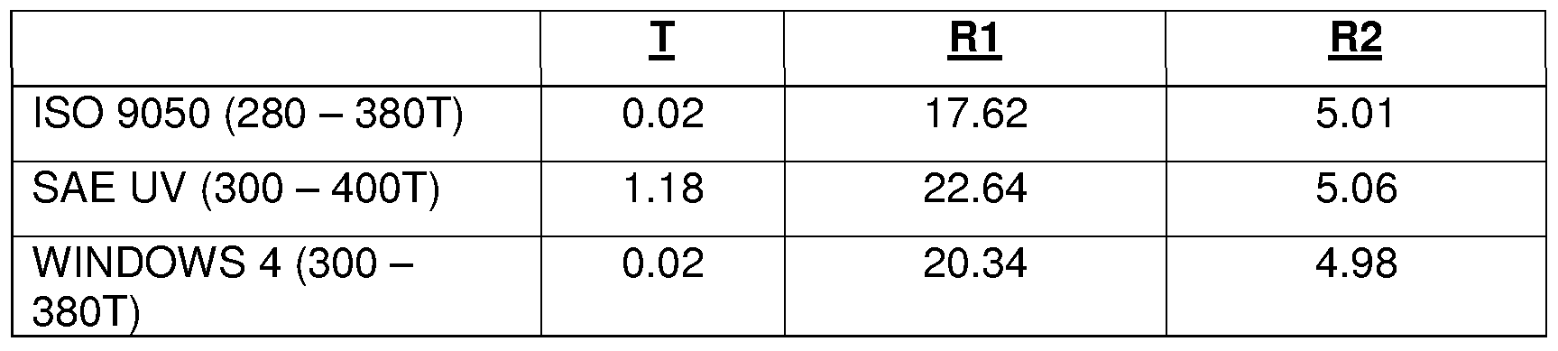
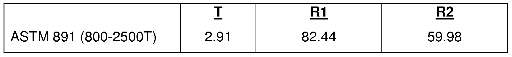
- T refers to the percent transmittance through the article
- FM refers to the percent reflectance of the article from the side closest to the coating
- R2 refers to the percent reflectance from the side farthest from the coating
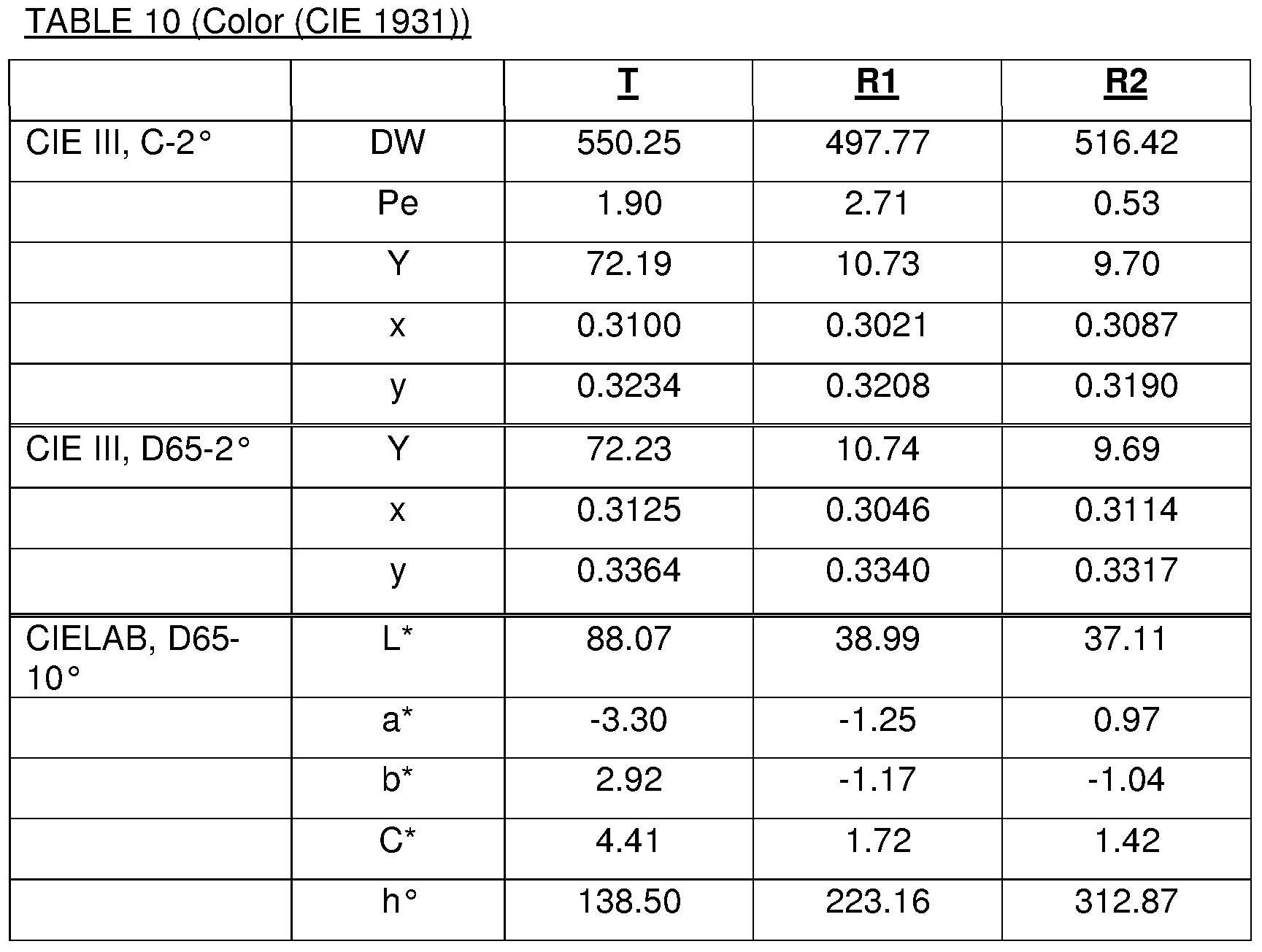
- DW refers to the dominent wavelength (in nanometers)
- Pe refers to the excitation purity.
- the color coordinates are those of the conventional CIE (1931 ) and CIELAB systems that will be understood by one of ordinary skill in the art.
- a laminated article was prepared and had the fol clear glass 2.0mm
- PVB 0.75mm protective overcoat 1000 A (85/15 wt.% silica/alumina) zinc stan n ate 302.6 A zinc oxide 101 A titanium 2O A silver 1 18.6 A zinc oxide 93.4 A zinc stannate 560.0 A zinc oxide 93.4 A titanium 2O A silver 126.4 A zinc oxide 103 A zinc stannate 618.4 A zinc oxide 103 A titanium 2O A silver 131.2 A zinc oxide 100.8 A zinc stannate 302.3 A
- Example 2 was the same as Example 1 above except that the
- PVB layer was replaced by a conventional optical adhesive.
- the optical adhesive used was Norland Optical Adhesive (No. 61 , UV curing).
- the interlayer was formed by placing the liquid optical adhesive (less than 0.5 cm 3 ) onto the coating and then placing the outer glass ply on the adhesive and curing the adhesive in accordance with the adhesive instructions. The thickness of the cured optical adhesive was not measured.
Abstract
Description


Claims
Priority Applications (7)
| Application Number | Priority Date | Filing Date | Title |
|---|---|---|---|
| CA2697488A CA2697488C (en) | 2007-08-24 | 2008-08-21 | Vehicle transparency |
| MX2010001937A MX337302B (en) | 2007-08-24 | 2008-08-21 | Vehicle transparency. |
| ES08798333.4T ES2666496T3 (en) | 2007-08-24 | 2008-08-21 | Transparency for vehicles |
| PL08798333T PL2183102T3 (en) | 2007-08-24 | 2008-08-21 | Vehicle transparency |
| CN200880109630.5A CN101808821B (en) | 2007-08-24 | 2008-08-21 | Vehicle transparency |
| JP2010522011A JP5675356B2 (en) | 2007-08-24 | 2008-08-21 | Transparency for vehicles |
| EP08798333.4A EP2183102B1 (en) | 2007-08-24 | 2008-08-21 | Vehicle transparency |
Applications Claiming Priority (2)
| Application Number | Priority Date | Filing Date | Title |
|---|---|---|---|
| US95779607P | 2007-08-24 | 2007-08-24 | |
| US60/957,796 | 2007-08-24 |
Publications (1)
| Publication Number | Publication Date |
|---|---|
| WO2009029466A1 true WO2009029466A1 (en) | 2009-03-05 |
Family
ID=40001478
Family Applications (1)
| Application Number | Title | Priority Date | Filing Date |
|---|---|---|---|
| PCT/US2008/073803 WO2009029466A1 (en) | 2007-08-24 | 2008-08-21 | Vehicle transparency |
Country Status (8)
| Country | Link |
|---|---|
| EP (1) | EP2183102B1 (en) |
| JP (1) | JP5675356B2 (en) |
| CN (1) | CN101808821B (en) |
| CA (1) | CA2697488C (en) |
| ES (1) | ES2666496T3 (en) |
| MX (1) | MX337302B (en) |
| PL (1) | PL2183102T3 (en) |
| WO (1) | WO2009029466A1 (en) |
Cited By (13)
| Publication number | Priority date | Publication date | Assignee | Title |
|---|---|---|---|---|
| WO2011147864A1 (en) | 2010-05-25 | 2011-12-01 | Agc Glass Europe | Solar control glazing with low solar factor |
| WO2011147875A1 (en) | 2010-05-25 | 2011-12-01 | Agc Glass Europe | Solar control glazing |
| WO2013079400A1 (en) | 2011-11-29 | 2013-06-06 | Agc Glass Europe | Solar-control glazing unit |
| WO2013104439A1 (en) * | 2012-01-10 | 2013-07-18 | Saint-Gobain Glass France | Transparent pane with electrically conductive coating |
| WO2013104438A1 (en) * | 2012-01-10 | 2013-07-18 | Saint-Gobain Glass France | Transparent panel with electrically conductive coating |
| WO2013109582A1 (en) * | 2012-01-17 | 2013-07-25 | Cardinal Cg Company | Low solar transmittance coatings |
| JP2013541490A (en) * | 2010-10-22 | 2013-11-14 | ピルキントン グループ リミテッド | How to coat glass |
| CN106116174A (en) * | 2016-06-20 | 2016-11-16 | 东莞市银建玻璃工程有限公司 | A kind of high-transparency three silver medal low e glass |
| WO2019110172A1 (en) * | 2017-12-05 | 2019-06-13 | Saint-Gobain Glass France | Composite pane having sun protection coating and thermal-radiation-reflecting coating |
| US10571610B2 (en) | 2014-11-21 | 2020-02-25 | Saint-Gobain Performance Plastics Corporation | Infra-red control optical films having metal nitride between encapsulating layers containing oxide |
| US10916354B2 (en) | 2016-09-15 | 2021-02-09 | Central Glass Company, Limited | Sunlight shielding member |
| EP3187917B1 (en) | 2014-10-14 | 2021-03-10 | Fuyao Glass Industry Group Co., Ltd. | Head-up display system |
| WO2022058693A1 (en) * | 2020-09-21 | 2022-03-24 | Saint-Gobain Glass France | Material comprising a substrate provided with a stack of thin layers having thermal properties |
Families Citing this family (10)
| Publication number | Priority date | Publication date | Assignee | Title |
|---|---|---|---|---|
| ES2774977T3 (en) | 2012-08-09 | 2020-07-23 | Saint Gobain | Laminated glass layout with electrical switching |
| BE1020862A3 (en) * | 2012-08-21 | 2014-06-03 | Agc Glass Europe | AUTOMOBILE GLAZING. |
| CA2881175C (en) | 2012-08-21 | 2019-06-25 | Saint-Gobain Glass France | Composite pane with electrically switchable optical properties |
| JP5859476B2 (en) * | 2013-04-11 | 2016-02-10 | 日東電工株式会社 | Infrared reflective film |
| US10618252B2 (en) * | 2017-04-12 | 2020-04-14 | Vitro Flat Glass Llc | Solar control coating for laminated glazing |
| CN110650841A (en) | 2017-05-12 | 2020-01-03 | 中央硝子株式会社 | Solar radiation shielding member |
| US11220455B2 (en) * | 2017-08-04 | 2022-01-11 | Vitro Flat Glass Llc | Flash annealing of silver coatings |
| US10788667B2 (en) * | 2017-08-31 | 2020-09-29 | Vitro Flat Glass Llc | Heads-up display and coating therefor |
| JP2021519258A (en) * | 2018-03-27 | 2021-08-10 | ピルキントン グループ リミテッド | Laminated glazing |
| JP2021519257A (en) * | 2018-03-27 | 2021-08-10 | ピルキントン グループ リミテッド | Laminated glazing |
Citations (11)
| Publication number | Priority date | Publication date | Assignee | Title |
|---|---|---|---|---|
| US4799745A (en) * | 1986-06-30 | 1989-01-24 | Southwall Technologies, Inc. | Heat reflecting composite films and glazing products containing the same |
| US5595825A (en) * | 1993-09-23 | 1997-01-21 | Saint-Gobain Vitrage | Transparent substrate provided with a stack of thin films acting on solar and/or infrared radiation |
| US6387515B1 (en) * | 1998-12-21 | 2002-05-14 | Saint-Gobain Vitrage | Transparent substrate comprising an antireflection coating |
| US20020136905A1 (en) * | 1999-11-24 | 2002-09-26 | Medwick Paul A. | Low shading coefficient and low emissivity coatings and coated articles |
| US20040009356A1 (en) * | 2002-05-03 | 2004-01-15 | Medwick Paul A. | Substrate having thermal management coating for an insulating glass unit |
| US20050155695A1 (en) * | 1998-05-08 | 2005-07-21 | O'shaughnessy Dennis J. | Shippable heat-treatable sputter coated article and method of making same |
| US20060280951A1 (en) * | 2003-09-17 | 2006-12-14 | Saint-Gobain Glass France | Transparent substrate comprising a stack of thin layers for electromagnetic armour |
| US20070020465A1 (en) * | 2005-07-20 | 2007-01-25 | Thiel James P | Heatable windshield |
| US20070081227A1 (en) * | 2005-10-11 | 2007-04-12 | Klaus Hartig | Low-emissivity coatings having high visible transmission and low solar heat gain coefficient |
| US20070082219A1 (en) * | 2003-11-28 | 2007-04-12 | Saint-Gobain Glass France | Transparent substrate which can be used alternatively or cumulatively for thermal control, electromagnetic armour and heated glazing |
| WO2007134015A2 (en) * | 2006-05-09 | 2007-11-22 | Ppg Industries Ohio, Inc. | Aesthetic transparency |
Family Cites Families (2)
| Publication number | Priority date | Publication date | Assignee | Title |
|---|---|---|---|---|
| FR2748743B1 (en) * | 1996-05-14 | 1998-06-19 | Saint Gobain Vitrage | GLASS WITH ANTI-REFLECTIVE COATING |
| US7588829B2 (en) * | 2002-05-31 | 2009-09-15 | Ppg Industries Ohio, Inc. | Article having an aesthetic coating |
-
2008
- 2008-08-21 EP EP08798333.4A patent/EP2183102B1/en active Active
- 2008-08-21 CN CN200880109630.5A patent/CN101808821B/en active Active
- 2008-08-21 JP JP2010522011A patent/JP5675356B2/en active Active
- 2008-08-21 CA CA2697488A patent/CA2697488C/en active Active
- 2008-08-21 PL PL08798333T patent/PL2183102T3/en unknown
- 2008-08-21 MX MX2010001937A patent/MX337302B/en active IP Right Grant
- 2008-08-21 ES ES08798333.4T patent/ES2666496T3/en active Active
- 2008-08-21 WO PCT/US2008/073803 patent/WO2009029466A1/en active Application Filing
Patent Citations (12)
| Publication number | Priority date | Publication date | Assignee | Title |
|---|---|---|---|---|
| US4799745A (en) * | 1986-06-30 | 1989-01-24 | Southwall Technologies, Inc. | Heat reflecting composite films and glazing products containing the same |
| US4799745B1 (en) * | 1986-06-30 | 1992-02-25 | Southwall Technologies Inc | |
| US5595825A (en) * | 1993-09-23 | 1997-01-21 | Saint-Gobain Vitrage | Transparent substrate provided with a stack of thin films acting on solar and/or infrared radiation |
| US20050155695A1 (en) * | 1998-05-08 | 2005-07-21 | O'shaughnessy Dennis J. | Shippable heat-treatable sputter coated article and method of making same |
| US6387515B1 (en) * | 1998-12-21 | 2002-05-14 | Saint-Gobain Vitrage | Transparent substrate comprising an antireflection coating |
| US20020136905A1 (en) * | 1999-11-24 | 2002-09-26 | Medwick Paul A. | Low shading coefficient and low emissivity coatings and coated articles |
| US20040009356A1 (en) * | 2002-05-03 | 2004-01-15 | Medwick Paul A. | Substrate having thermal management coating for an insulating glass unit |
| US20060280951A1 (en) * | 2003-09-17 | 2006-12-14 | Saint-Gobain Glass France | Transparent substrate comprising a stack of thin layers for electromagnetic armour |
| US20070082219A1 (en) * | 2003-11-28 | 2007-04-12 | Saint-Gobain Glass France | Transparent substrate which can be used alternatively or cumulatively for thermal control, electromagnetic armour and heated glazing |
| US20070020465A1 (en) * | 2005-07-20 | 2007-01-25 | Thiel James P | Heatable windshield |
| US20070081227A1 (en) * | 2005-10-11 | 2007-04-12 | Klaus Hartig | Low-emissivity coatings having high visible transmission and low solar heat gain coefficient |
| WO2007134015A2 (en) * | 2006-05-09 | 2007-11-22 | Ppg Industries Ohio, Inc. | Aesthetic transparency |
Cited By (36)
| Publication number | Priority date | Publication date | Assignee | Title |
|---|---|---|---|---|
| AU2011257256B2 (en) * | 2010-05-25 | 2015-05-14 | Agc Glass Europe | Solar control glazing |
| WO2011147875A1 (en) | 2010-05-25 | 2011-12-01 | Agc Glass Europe | Solar control glazing |
| BE1019346A3 (en) * | 2010-05-25 | 2012-06-05 | Agc Glass Europe | GLAZING OF SOLAR CONTROL. |
| BE1019345A3 (en) * | 2010-05-25 | 2012-06-05 | Agc Glass Europe | SOLAR CONTROL GLAZING WITH LOW SOLAR FACTOR. |
| CN102918434A (en) * | 2010-05-25 | 2013-02-06 | 旭硝子欧洲玻璃公司 | Solar control glazing |
| CN102918433A (en) * | 2010-05-25 | 2013-02-06 | 旭硝子欧洲玻璃公司 | Solar control glazing with low solar factor |
| WO2011147864A1 (en) | 2010-05-25 | 2011-12-01 | Agc Glass Europe | Solar control glazing with low solar factor |
| US10025010B2 (en) | 2010-05-25 | 2018-07-17 | Agc Glass Europe | Solar control glazing with low solar factor |
| US9709717B2 (en) | 2010-05-25 | 2017-07-18 | Agc Glass Europe | Solar control glazing |
| EA025674B1 (en) * | 2010-05-25 | 2017-01-30 | Агк Гласс Юроп | Solar control glazing with low solar factor |
| JP2013532306A (en) * | 2010-05-25 | 2013-08-15 | エージーシー グラス ユーロップ | Solar control glazing with low solar factor |
| CN102918434B (en) * | 2010-05-25 | 2016-11-23 | 旭硝子欧洲玻璃公司 | Sunlight controls door glass |
| EA024158B1 (en) * | 2010-05-25 | 2016-08-31 | Агк Гласс Юроп | Solar control glazing |
| AU2011257245B2 (en) * | 2010-05-25 | 2015-02-05 | Agc Glass Europe | Solar control glazing with low solar factor |
| US10167224B2 (en) | 2010-10-22 | 2019-01-01 | Pilkington Group Limited | Method of coating glass |
| JP2013541490A (en) * | 2010-10-22 | 2013-11-14 | ピルキントン グループ リミテッド | How to coat glass |
| WO2013079400A1 (en) | 2011-11-29 | 2013-06-06 | Agc Glass Europe | Solar-control glazing unit |
| WO2013104439A1 (en) * | 2012-01-10 | 2013-07-18 | Saint-Gobain Glass France | Transparent pane with electrically conductive coating |
| US9215760B2 (en) | 2012-01-10 | 2015-12-15 | Saint-Gobain Glass France | Transparent pane with electrically conductive coating |
| KR101589854B1 (en) | 2012-01-10 | 2016-01-28 | 쌩-고벵 글래스 프랑스 | Transparent pane with electrically conductive coating |
| US9359807B2 (en) | 2012-01-10 | 2016-06-07 | Saint-Gobain Glass France | Transparent panel with electrically conductive coating |
| KR20140099548A (en) * | 2012-01-10 | 2014-08-12 | 쌩-고벵 글래스 프랑스 | Transparent pane with electrically conductive coating |
| EA026887B1 (en) * | 2012-01-10 | 2017-05-31 | Сэн-Гобэн Гласс Франс | Transparent pane with electrically conductive coating and method for producing said pane |
| EA027187B1 (en) * | 2012-01-10 | 2017-06-30 | Сэн-Гобэн Гласс Франс | Transparent pane with electrically conductive coating and method for producing the same |
| WO2013104438A1 (en) * | 2012-01-10 | 2013-07-18 | Saint-Gobain Glass France | Transparent panel with electrically conductive coating |
| US10040719B2 (en) | 2012-01-17 | 2018-08-07 | Cardinal Cg Company | Low solar transmittance coatings |
| WO2013109582A1 (en) * | 2012-01-17 | 2013-07-25 | Cardinal Cg Company | Low solar transmittance coatings |
| EP2804755B1 (en) | 2012-01-17 | 2019-06-19 | Cardinal CG Company | Low solar transmittance coatings |
| EP3187917B1 (en) | 2014-10-14 | 2021-03-10 | Fuyao Glass Industry Group Co., Ltd. | Head-up display system |
| US10571610B2 (en) | 2014-11-21 | 2020-02-25 | Saint-Gobain Performance Plastics Corporation | Infra-red control optical films having metal nitride between encapsulating layers containing oxide |
| CN106116174A (en) * | 2016-06-20 | 2016-11-16 | 东莞市银建玻璃工程有限公司 | A kind of high-transparency three silver medal low e glass |
| US10916354B2 (en) | 2016-09-15 | 2021-02-09 | Central Glass Company, Limited | Sunlight shielding member |
| WO2019110172A1 (en) * | 2017-12-05 | 2019-06-13 | Saint-Gobain Glass France | Composite pane having sun protection coating and thermal-radiation-reflecting coating |
| US11001037B2 (en) | 2017-12-05 | 2021-05-11 | Saint-Gobain Glass France | Composite pane having sun protection coating and thermal-radiation-reflecting coating |
| WO2022058693A1 (en) * | 2020-09-21 | 2022-03-24 | Saint-Gobain Glass France | Material comprising a substrate provided with a stack of thin layers having thermal properties |
| FR3114315A1 (en) * | 2020-09-21 | 2022-03-25 | Saint-Gobain Glass France | MATERIAL COMPRISING A SUBSTRATE PROVIDED WITH A STACK OF THIN LAYERS WITH THERMAL PROPERTIES |
Also Published As
| Publication number | Publication date |
|---|---|
| CN101808821A (en) | 2010-08-18 |
| EP2183102B1 (en) | 2018-03-14 |
| ES2666496T3 (en) | 2018-05-04 |
| MX337302B (en) | 2016-02-24 |
| PL2183102T3 (en) | 2018-08-31 |
| JP5675356B2 (en) | 2015-02-25 |
| EP2183102A1 (en) | 2010-05-12 |
| CA2697488C (en) | 2013-08-13 |
| CN101808821B (en) | 2013-11-06 |
| CA2697488A1 (en) | 2009-03-05 |
| JP2010536707A (en) | 2010-12-02 |
| MX2010001937A (en) | 2010-03-11 |
Similar Documents
| Publication | Publication Date | Title |
|---|---|---|
| US8025957B2 (en) | Vehicle transparency | |
| CA2697488C (en) | Vehicle transparency | |
| EP1476300B1 (en) | Solar control coating | |
| EP1742889B1 (en) | Hybrid coating stack | |
| CA2615919C (en) | Heatable windshield | |
| EP2212107B1 (en) | Electromagnetic radiation shielding device | |
| EP3527541B1 (en) | Solar control coatings providing increased absorption or tint | |
| AU2019222698B2 (en) | Coated article having a protective coating containing silicon nitride and/or silicon oxynitride | |
| US20080280147A1 (en) | Vehicle transparency | |
| US20070212530A1 (en) | Restrictive and Preferential Routing in a Distributed Mobile Switching Center Environment with Media Gateway Clusters |
Legal Events
| Date | Code | Title | Description |
|---|---|---|---|
| WWE | Wipo information: entry into national phase |
Ref document number: 200880109630.5 Country of ref document: CN |
|
| 121 | Ep: the epo has been informed by wipo that ep was designated in this application |
Ref document number: 08798333 Country of ref document: EP Kind code of ref document: A1 |
|
| WWE | Wipo information: entry into national phase |
Ref document number: MX/A/2010/001937 Country of ref document: MX Ref document number: 2008798333 Country of ref document: EP |
|
| WWE | Wipo information: entry into national phase |
Ref document number: 1209/DELNP/2010 Country of ref document: IN |
|
| ENP | Entry into the national phase |
Ref document number: 2010522011 Country of ref document: JP Kind code of ref document: A |
|
| WWE | Wipo information: entry into national phase |
Ref document number: 2697488 Country of ref document: CA |
|
| NENP | Non-entry into the national phase |
Ref country code: DE |