WO2009152212A1 - Preparation of high performance ultra filtration hollow fiber membrane - Google Patents
Preparation of high performance ultra filtration hollow fiber membrane Download PDFInfo
- Publication number
- WO2009152212A1 WO2009152212A1 PCT/US2009/046851 US2009046851W WO2009152212A1 WO 2009152212 A1 WO2009152212 A1 WO 2009152212A1 US 2009046851 W US2009046851 W US 2009046851W WO 2009152212 A1 WO2009152212 A1 WO 2009152212A1
- Authority
- WO
- WIPO (PCT)
- Prior art keywords
- pvp
- water
- fiber membrane
- solution
- hollow
- Prior art date
Links
- 239000012528 membrane Substances 0.000 title claims abstract description 98
- 239000012510 hollow fiber Substances 0.000 title claims abstract description 36
- 238000000108 ultra-filtration Methods 0.000 title abstract description 9
- 238000002360 preparation method Methods 0.000 title description 3
- XLYOFNOQVPJJNP-UHFFFAOYSA-N water Substances O XLYOFNOQVPJJNP-UHFFFAOYSA-N 0.000 claims abstract description 87
- 238000000034 method Methods 0.000 claims abstract description 55
- 239000002904 solvent Substances 0.000 claims abstract description 55
- 239000000203 mixture Substances 0.000 claims abstract description 45
- 229920000036 polyvinylpyrrolidone Polymers 0.000 claims description 77
- 239000001267 polyvinylpyrrolidone Substances 0.000 claims description 77
- 235000013855 polyvinylpyrrolidone Nutrition 0.000 claims description 77
- 239000000835 fiber Substances 0.000 claims description 34
- 238000009987 spinning Methods 0.000 claims description 32
- 229920006393 polyether sulfone Polymers 0.000 claims description 27
- 239000004695 Polyether sulfone Substances 0.000 claims description 26
- 238000001879 gelation Methods 0.000 claims description 19
- 230000004907 flux Effects 0.000 claims description 18
- 239000012530 fluid Substances 0.000 claims description 17
- 238000001223 reverse osmosis Methods 0.000 claims description 16
- 238000005266 casting Methods 0.000 claims description 15
- WHNWPMSKXPGLAX-UHFFFAOYSA-N N-Vinyl-2-pyrrolidone Chemical compound C=CN1CCCC1=O WHNWPMSKXPGLAX-UHFFFAOYSA-N 0.000 claims description 13
- SUKJFIGYRHOWBL-UHFFFAOYSA-N sodium hypochlorite Chemical compound [Na+].Cl[O-] SUKJFIGYRHOWBL-UHFFFAOYSA-N 0.000 claims description 9
- PEDCQBHIVMGVHV-UHFFFAOYSA-N Glycerine Chemical compound OCC(O)CO PEDCQBHIVMGVHV-UHFFFAOYSA-N 0.000 claims description 6
- 230000002209 hydrophobic effect Effects 0.000 claims description 5
- 238000004519 manufacturing process Methods 0.000 claims description 5
- 239000005708 Sodium hypochlorite Substances 0.000 claims description 4
- 238000007872 degassing Methods 0.000 claims description 4
- 239000011159 matrix material Substances 0.000 claims description 4
- 238000001914 filtration Methods 0.000 claims description 3
- 238000002156 mixing Methods 0.000 claims description 3
- 239000012466 permeate Substances 0.000 claims description 3
- 229920012266 Poly(ether sulfone) PES Polymers 0.000 claims description 2
- 230000001112 coagulating effect Effects 0.000 claims description 2
- 239000002798 polar solvent Substances 0.000 claims 10
- IJGRMHOSHXDMSA-UHFFFAOYSA-N Atomic nitrogen Chemical compound N#N IJGRMHOSHXDMSA-UHFFFAOYSA-N 0.000 claims 1
- 229920003081 Povidone K 30 Polymers 0.000 claims 1
- 229920003082 Povidone K 90 Polymers 0.000 claims 1
- 229920006317 cationic polymer Polymers 0.000 claims 1
- 229910001873 dinitrogen Inorganic materials 0.000 claims 1
- 238000001125 extrusion Methods 0.000 claims 1
- 238000004064 recycling Methods 0.000 claims 1
- WBHQBSYUUJJSRZ-UHFFFAOYSA-M sodium bisulfate Chemical compound [Na+].OS([O-])(=O)=O WBHQBSYUUJJSRZ-UHFFFAOYSA-M 0.000 claims 1
- 229920000642 polymer Polymers 0.000 abstract description 35
- 230000008569 process Effects 0.000 abstract description 29
- 230000015572 biosynthetic process Effects 0.000 abstract description 10
- 239000011148 porous material Substances 0.000 abstract description 10
- 238000000926 separation method Methods 0.000 abstract description 7
- 230000035699 permeability Effects 0.000 abstract description 6
- 229920001600 hydrophobic polymer Polymers 0.000 abstract description 4
- 229920003169 water-soluble polymer Polymers 0.000 abstract description 4
- 238000005345 coagulation Methods 0.000 abstract description 2
- 230000015271 coagulation Effects 0.000 abstract description 2
- 238000009792 diffusion process Methods 0.000 abstract description 2
- 238000000614 phase inversion technique Methods 0.000 abstract 1
- 239000000243 solution Substances 0.000 description 30
- 238000006243 chemical reaction Methods 0.000 description 13
- ZMXDDKWLCZADIW-UHFFFAOYSA-N N,N-Dimethylformamide Chemical compound CN(C)C=O ZMXDDKWLCZADIW-UHFFFAOYSA-N 0.000 description 12
- 238000002474 experimental method Methods 0.000 description 11
- 239000012071 phase Substances 0.000 description 8
- FXHOOIRPVKKKFG-UHFFFAOYSA-N N,N-Dimethylacetamide Chemical compound CN(C)C(C)=O FXHOOIRPVKKKFG-UHFFFAOYSA-N 0.000 description 6
- SECXISVLQFMRJM-UHFFFAOYSA-N N-Methylpyrrolidone Chemical compound CN1CCCC1=O SECXISVLQFMRJM-UHFFFAOYSA-N 0.000 description 6
- 238000005191 phase separation Methods 0.000 description 6
- 238000001556 precipitation Methods 0.000 description 6
- 238000012360 testing method Methods 0.000 description 6
- IAZDPXIOMUYVGZ-UHFFFAOYSA-N Dimethylsulphoxide Chemical compound CS(C)=O IAZDPXIOMUYVGZ-UHFFFAOYSA-N 0.000 description 5
- 229910019093 NaOCl Inorganic materials 0.000 description 5
- 239000000654 additive Substances 0.000 description 5
- 238000009472 formulation Methods 0.000 description 5
- 239000002245 particle Substances 0.000 description 5
- 230000008901 benefit Effects 0.000 description 4
- 230000007246 mechanism Effects 0.000 description 4
- 239000000047 product Substances 0.000 description 4
- HEMHJVSKTPXQMS-UHFFFAOYSA-M Sodium hydroxide Chemical compound [OH-].[Na+] HEMHJVSKTPXQMS-UHFFFAOYSA-M 0.000 description 3
- 229920001477 hydrophilic polymer Polymers 0.000 description 3
- 230000002035 prolonged effect Effects 0.000 description 3
- 238000001878 scanning electron micrograph Methods 0.000 description 3
- 230000000996 additive effect Effects 0.000 description 2
- 230000001174 ascending effect Effects 0.000 description 2
- 230000003111 delayed effect Effects 0.000 description 2
- 230000001419 dependent effect Effects 0.000 description 2
- 238000004090 dissolution Methods 0.000 description 2
- WQYVRQLZKVEZGA-UHFFFAOYSA-N hypochlorite Chemical compound Cl[O-] WQYVRQLZKVEZGA-UHFFFAOYSA-N 0.000 description 2
- 239000004615 ingredient Substances 0.000 description 2
- 239000010410 layer Substances 0.000 description 2
- 230000014759 maintenance of location Effects 0.000 description 2
- 239000000463 material Substances 0.000 description 2
- 239000003960 organic solvent Substances 0.000 description 2
- 229920000191 poly(N-vinyl pyrrolidone) Polymers 0.000 description 2
- HNJBEVLQSNELDL-UHFFFAOYSA-N pyrrolidin-2-one Chemical group O=C1CCCN1 HNJBEVLQSNELDL-UHFFFAOYSA-N 0.000 description 2
- 229910002059 quaternary alloy Inorganic materials 0.000 description 2
- 239000007787 solid Substances 0.000 description 2
- 238000007711 solidification Methods 0.000 description 2
- 230000008023 solidification Effects 0.000 description 2
- 230000001629 suppression Effects 0.000 description 2
- 239000011800 void material Substances 0.000 description 2
- 238000004075 wastewater filtration Methods 0.000 description 2
- 239000003643 water by type Substances 0.000 description 2
- 238000004804 winding Methods 0.000 description 2
- DWKNOLCXIFYNFV-HSZRJFAPSA-N 2-[[(2r)-1-[1-[(4-chloro-3-methylphenyl)methyl]piperidin-4-yl]-5-oxopyrrolidine-2-carbonyl]amino]-n,n,6-trimethylpyridine-4-carboxamide Chemical compound CN(C)C(=O)C1=CC(C)=NC(NC(=O)[C@@H]2N(C(=O)CC2)C2CCN(CC=3C=C(C)C(Cl)=CC=3)CC2)=C1 DWKNOLCXIFYNFV-HSZRJFAPSA-N 0.000 description 1
- UXHQLGLGLZKHTC-CUNXSJBXSA-N 4-[(3s,3ar)-3-cyclopentyl-7-(4-hydroxypiperidine-1-carbonyl)-3,3a,4,5-tetrahydropyrazolo[3,4-f]quinolin-2-yl]-2-chlorobenzonitrile Chemical compound C1CC(O)CCN1C(=O)C1=CC=C(C=2[C@@H]([C@H](C3CCCC3)N(N=2)C=2C=C(Cl)C(C#N)=CC=2)CC2)C2=N1 UXHQLGLGLZKHTC-CUNXSJBXSA-N 0.000 description 1
- RSIWALKZYXPAGW-NSHDSACASA-N 6-(3-fluorophenyl)-3-methyl-7-[(1s)-1-(7h-purin-6-ylamino)ethyl]-[1,3]thiazolo[3,2-a]pyrimidin-5-one Chemical compound C=1([C@@H](NC=2C=3N=CNC=3N=CN=2)C)N=C2SC=C(C)N2C(=O)C=1C1=CC=CC(F)=C1 RSIWALKZYXPAGW-NSHDSACASA-N 0.000 description 1
- KZBUYRJDOAKODT-UHFFFAOYSA-N Chlorine Chemical compound ClCl KZBUYRJDOAKODT-UHFFFAOYSA-N 0.000 description 1
- ZAMOUSCENKQFHK-UHFFFAOYSA-N Chlorine atom Chemical compound [Cl] ZAMOUSCENKQFHK-UHFFFAOYSA-N 0.000 description 1
- 239000004952 Polyamide Substances 0.000 description 1
- DWAQJAXMDSEUJJ-UHFFFAOYSA-M Sodium bisulfite Chemical compound [Na+].OS([O-])=O DWAQJAXMDSEUJJ-UHFFFAOYSA-M 0.000 description 1
- 238000010521 absorption reaction Methods 0.000 description 1
- 238000013019 agitation Methods 0.000 description 1
- 239000012670 alkaline solution Substances 0.000 description 1
- 238000011001 backwashing Methods 0.000 description 1
- 230000001580 bacterial effect Effects 0.000 description 1
- 229920005601 base polymer Polymers 0.000 description 1
- 230000009286 beneficial effect Effects 0.000 description 1
- 239000000460 chlorine Substances 0.000 description 1
- 229910052801 chlorine Inorganic materials 0.000 description 1
- 239000000084 colloidal system Substances 0.000 description 1
- 239000000356 contaminant Substances 0.000 description 1
- 230000008602 contraction Effects 0.000 description 1
- 230000001934 delay Effects 0.000 description 1
- 238000010612 desalination reaction Methods 0.000 description 1
- 230000001627 detrimental effect Effects 0.000 description 1
- 238000010586 diagram Methods 0.000 description 1
- 238000000502 dialysis Methods 0.000 description 1
- 229960001760 dimethyl sulfoxide Drugs 0.000 description 1
- 239000006185 dispersion Substances 0.000 description 1
- 230000000694 effects Effects 0.000 description 1
- 230000008030 elimination Effects 0.000 description 1
- 238000003379 elimination reaction Methods 0.000 description 1
- 239000003623 enhancer Substances 0.000 description 1
- 230000007613 environmental effect Effects 0.000 description 1
- 238000011156 evaluation Methods 0.000 description 1
- 238000001704 evaporation Methods 0.000 description 1
- 230000008020 evaporation Effects 0.000 description 1
- 239000012456 homogeneous solution Substances 0.000 description 1
- 239000007788 liquid Substances 0.000 description 1
- 230000007774 longterm Effects 0.000 description 1
- 238000001471 micro-filtration Methods 0.000 description 1
- 244000005700 microbiome Species 0.000 description 1
- 238000012544 monitoring process Methods 0.000 description 1
- 238000001728 nano-filtration Methods 0.000 description 1
- 238000005457 optimization Methods 0.000 description 1
- 239000007800 oxidant agent Substances 0.000 description 1
- 238000012856 packing Methods 0.000 description 1
- 230000002093 peripheral effect Effects 0.000 description 1
- 229920002647 polyamide Polymers 0.000 description 1
- 230000000750 progressive effect Effects 0.000 description 1
- 238000000746 purification Methods 0.000 description 1
- 238000010791 quenching Methods 0.000 description 1
- 239000012429 reaction media Substances 0.000 description 1
- 238000007142 ring opening reaction Methods 0.000 description 1
- 235000010267 sodium hydrogen sulphite Nutrition 0.000 description 1
- 239000004289 sodium hydrogen sulphite Substances 0.000 description 1
- 239000007790 solid phase Substances 0.000 description 1
- 238000001179 sorption measurement Methods 0.000 description 1
- 241000894007 species Species 0.000 description 1
- 239000000126 substance Substances 0.000 description 1
- 239000002344 surface layer Substances 0.000 description 1
- 230000003746 surface roughness Effects 0.000 description 1
- 239000000725 suspension Substances 0.000 description 1
- 230000002459 sustained effect Effects 0.000 description 1
- 208000024891 symptom Diseases 0.000 description 1
- 230000007704 transition Effects 0.000 description 1
- 239000002699 waste material Substances 0.000 description 1
Classifications
-
- C—CHEMISTRY; METALLURGY
- C02—TREATMENT OF WATER, WASTE WATER, SEWAGE, OR SLUDGE
- C02F—TREATMENT OF WATER, WASTE WATER, SEWAGE, OR SLUDGE
- C02F1/00—Treatment of water, waste water, or sewage
- C02F1/44—Treatment of water, waste water, or sewage by dialysis, osmosis or reverse osmosis
- C02F1/444—Treatment of water, waste water, or sewage by dialysis, osmosis or reverse osmosis by ultrafiltration or microfiltration
-
- B—PERFORMING OPERATIONS; TRANSPORTING
- B01—PHYSICAL OR CHEMICAL PROCESSES OR APPARATUS IN GENERAL
- B01D—SEPARATION
- B01D69/00—Semi-permeable membranes for separation processes or apparatus characterised by their form, structure or properties; Manufacturing processes specially adapted therefor
- B01D69/02—Semi-permeable membranes for separation processes or apparatus characterised by their form, structure or properties; Manufacturing processes specially adapted therefor characterised by their properties
-
- B—PERFORMING OPERATIONS; TRANSPORTING
- B01—PHYSICAL OR CHEMICAL PROCESSES OR APPARATUS IN GENERAL
- B01D—SEPARATION
- B01D69/00—Semi-permeable membranes for separation processes or apparatus characterised by their form, structure or properties; Manufacturing processes specially adapted therefor
- B01D69/08—Hollow fibre membranes
- B01D69/087—Details relating to the spinning process
-
- B—PERFORMING OPERATIONS; TRANSPORTING
- B01—PHYSICAL OR CHEMICAL PROCESSES OR APPARATUS IN GENERAL
- B01D—SEPARATION
- B01D71/00—Semi-permeable membranes for separation processes or apparatus characterised by the material; Manufacturing processes specially adapted therefor
- B01D71/06—Organic material
- B01D71/44—Polymers obtained by reactions only involving carbon-to-carbon unsaturated bonds, not provided for in a single one of groups B01D71/26-B01D71/42
- B01D71/441—Polyvinylpyrrolidone
-
- B—PERFORMING OPERATIONS; TRANSPORTING
- B01—PHYSICAL OR CHEMICAL PROCESSES OR APPARATUS IN GENERAL
- B01D—SEPARATION
- B01D71/00—Semi-permeable membranes for separation processes or apparatus characterised by the material; Manufacturing processes specially adapted therefor
- B01D71/06—Organic material
- B01D71/66—Polymers having sulfur in the main chain, with or without nitrogen, oxygen or carbon only
- B01D71/68—Polysulfones; Polyethersulfones
-
- C—CHEMISTRY; METALLURGY
- C08—ORGANIC MACROMOLECULAR COMPOUNDS; THEIR PREPARATION OR CHEMICAL WORKING-UP; COMPOSITIONS BASED THEREON
- C08L—COMPOSITIONS OF MACROMOLECULAR COMPOUNDS
- C08L39/00—Compositions of homopolymers or copolymers of compounds having one or more unsaturated aliphatic radicals, each having only one carbon-to-carbon double bond, and at least one being terminated by a single or double bond to nitrogen or by a heterocyclic ring containing nitrogen; Compositions of derivatives of such polymers
- C08L39/04—Homopolymers or copolymers of monomers containing heterocyclic rings having nitrogen as ring member
- C08L39/06—Homopolymers or copolymers of N-vinyl-pyrrolidones
-
- D—TEXTILES; PAPER
- D01—NATURAL OR MAN-MADE THREADS OR FIBRES; SPINNING
- D01D—MECHANICAL METHODS OR APPARATUS IN THE MANUFACTURE OF ARTIFICIAL FILAMENTS, THREADS, FIBRES, BRISTLES OR RIBBONS
- D01D1/00—Treatment of filament-forming or like material
- D01D1/02—Preparation of spinning solutions
-
- D—TEXTILES; PAPER
- D01—NATURAL OR MAN-MADE THREADS OR FIBRES; SPINNING
- D01D—MECHANICAL METHODS OR APPARATUS IN THE MANUFACTURE OF ARTIFICIAL FILAMENTS, THREADS, FIBRES, BRISTLES OR RIBBONS
- D01D5/00—Formation of filaments, threads, or the like
- D01D5/24—Formation of filaments, threads, or the like with a hollow structure; Spinnerette packs therefor
-
- D—TEXTILES; PAPER
- D01—NATURAL OR MAN-MADE THREADS OR FIBRES; SPINNING
- D01F—CHEMICAL FEATURES IN THE MANUFACTURE OF ARTIFICIAL FILAMENTS, THREADS, FIBRES, BRISTLES OR RIBBONS; APPARATUS SPECIALLY ADAPTED FOR THE MANUFACTURE OF CARBON FILAMENTS
- D01F6/00—Monocomponent artificial filaments or the like of synthetic polymers; Manufacture thereof
- D01F6/44—Monocomponent artificial filaments or the like of synthetic polymers; Manufacture thereof from mixtures of polymers obtained by reactions only involving carbon-to-carbon unsaturated bonds as major constituent with other polymers or low-molecular-weight compounds
-
- D—TEXTILES; PAPER
- D01—NATURAL OR MAN-MADE THREADS OR FIBRES; SPINNING
- D01F—CHEMICAL FEATURES IN THE MANUFACTURE OF ARTIFICIAL FILAMENTS, THREADS, FIBRES, BRISTLES OR RIBBONS; APPARATUS SPECIALLY ADAPTED FOR THE MANUFACTURE OF CARBON FILAMENTS
- D01F6/00—Monocomponent artificial filaments or the like of synthetic polymers; Manufacture thereof
- D01F6/88—Monocomponent artificial filaments or the like of synthetic polymers; Manufacture thereof from mixtures of polycondensation products as major constituent with other polymers or low-molecular-weight compounds
- D01F6/94—Monocomponent artificial filaments or the like of synthetic polymers; Manufacture thereof from mixtures of polycondensation products as major constituent with other polymers or low-molecular-weight compounds of other polycondensation products
-
- B—PERFORMING OPERATIONS; TRANSPORTING
- B01—PHYSICAL OR CHEMICAL PROCESSES OR APPARATUS IN GENERAL
- B01D—SEPARATION
- B01D2323/00—Details relating to membrane preparation
- B01D2323/02—Hydrophilization
-
- B—PERFORMING OPERATIONS; TRANSPORTING
- B01—PHYSICAL OR CHEMICAL PROCESSES OR APPARATUS IN GENERAL
- B01D—SEPARATION
- B01D2323/00—Details relating to membrane preparation
- B01D2323/15—Use of additives
- B01D2323/18—Pore-control agents or pore formers
-
- B—PERFORMING OPERATIONS; TRANSPORTING
- B01—PHYSICAL OR CHEMICAL PROCESSES OR APPARATUS IN GENERAL
- B01D—SEPARATION
- B01D2323/00—Details relating to membrane preparation
- B01D2323/219—Specific solvent system
- B01D2323/22—Specific non-solvents or non-solvent system
-
- B—PERFORMING OPERATIONS; TRANSPORTING
- B01—PHYSICAL OR CHEMICAL PROCESSES OR APPARATUS IN GENERAL
- B01D—SEPARATION
- B01D2325/00—Details relating to properties of membranes
- B01D2325/02—Details relating to pores or porosity of the membranes
- B01D2325/022—Asymmetric membranes
-
- B—PERFORMING OPERATIONS; TRANSPORTING
- B01—PHYSICAL OR CHEMICAL PROCESSES OR APPARATUS IN GENERAL
- B01D—SEPARATION
- B01D2325/00—Details relating to properties of membranes
- B01D2325/34—Molecular weight or degree of polymerisation
-
- B—PERFORMING OPERATIONS; TRANSPORTING
- B01—PHYSICAL OR CHEMICAL PROCESSES OR APPARATUS IN GENERAL
- B01D—SEPARATION
- B01D2325/00—Details relating to properties of membranes
- B01D2325/34—Molecular weight or degree of polymerisation
- B01D2325/341—At least two polymers of same structure but different molecular weight
-
- B—PERFORMING OPERATIONS; TRANSPORTING
- B01—PHYSICAL OR CHEMICAL PROCESSES OR APPARATUS IN GENERAL
- B01D—SEPARATION
- B01D61/00—Processes of separation using semi-permeable membranes, e.g. dialysis, osmosis or ultrafiltration; Apparatus, accessories or auxiliary operations specially adapted therefor
- B01D61/14—Ultrafiltration; Microfiltration
- B01D61/145—Ultrafiltration
Definitions
- Embodiments of the present invention relate to a multipolymeric dope solution from which an asymmetric and hydrophilic ultra filtration grade hollow fiber membrane could be made in an environmentally friendly process with recycle of effluent.
- Synthetic membranes are generally used for a variety of applications including desalination, gas separation, bacterial and particle filtration, and dialysis.
- the properties of the membranes depend on their morphology, i.e., properties such as cross-sectional symmetry or asymmetry, pore sizes, pore shapes and the polymeric material from which the membrane is made.
- These membranes could be hydrophobic or hydrophilic according to reaction conditions, dope composition, their manufacturing methodologies including post treatment processes.
- Hydrophilic membranes are less prone to fouling when used in particulate or colloidal suspensions
- Different pore size membranes are used for different separation processes, ranging progressively from the relatively large pore sizes used in micro filtration, then ultra filtration, nanofiltration, reverse osmosis, and ultimately down to gas separation membranes with pores the size of gas molecules. All these types of filtration are pressure driven processes and are distinguished by the size of the particles or molecules that the membrane is capable of retaining or passing.
- membranes are made by first preparing a casting solution from a chosen polymer formulation and a suitable solvent. In the process of membrane making the polymer is converted into solid phase. Immersing the polymer solution into a quench bath comprising of non-solvent normally carries out precipitation of polymer. Fundamentally phase separation process had been chosen to fabricate these membranes. Three different techniques are involved in a phase separation method:
- the physical shapes of synthetic membranes can be made in different varieties based on different applications.
- Flat sheet, tubular or non-reinforced hollow fibers are used in a wide range of areas according to the merit of the specific membrane and application.
- Hollow fibers are mostly preferred for their high packing density, which provides higher surface areas per unit volume compared to other membrane configurations.
- the current hollow fiber-based membranes are limited by lower fluxes that can be achieved on a sustainable basis, and also they are limited in terms of turbidity levels, which can be tolerated on a long-term operation.
- This invention here is targeted towards overcoming these limitations in the current generation hollow fiber membranes to expand its application for RO pretreatment processes including elimination of media filters and clarifiers even if turbidity conditions are high. It is desired that while high and sustained fluxes are achieved at higher inlet turbidities basic properties of hollow fiber for backwashing and also in terms of burst and elongation strengths are also improved. It would also be desirable to make the process of spinning hollow fibers less dependent on multiple and small variations like temperature, humidity and need for extremely complex conditions in RO bore fluid composition, Gelation bath composition etc. It is also the target to make the process environmentally friendly by minimizing use of solvent for example in bore fluid, gelation bath air gap for membrane spinning etc and also to recycle most of the water used in the process of spinning.
- the effluent water is contaminated with solvent and traces of PVP.
- the effluent is processed through a Membrane bioreactor process and all the water is recycled back in to the system to make it an environmentally friendly process.
- the present invention relates to a process of making a multi polymeric solution, which can produce of hydrophilic & asymmetric ultra filtration hollow fiber membranes from Polyethersulfone (PES) using two or more different grades of polyvinylpyrrolidone (PVP) in conjunction as additives, water (H 2 O) as a non-solvent and a suitable solvent from the group of N-methylpyrrolidone (NMP), Dimethylacetamide (DMAc), Dimethylformamide (DMF) and Dimethylsulfoxide (DMSO).
- PES Polyethersulfone
- PVP polyvinylpyrrolidone
- H 2 O water
- suitable solvent from the group of N-methylpyrrolidone (NMP), Dimethylacetamide (DMAc), Dimethylformamide (DMF) and Dimethylsulfoxide (DMSO).
- the system consists of bore fluid tank (1) fitted with gear pump (3) and spinning reservoir (2) fitted with gear pump (4), both connected to spinneret (5) for feeding bore fluid and dope solution respectively.
- Gelation bath (6) and casting vat (8) are fitted with guiding pulleys (7) to carry the spun fiber through them, which is pulled by a VFD controlled winding pulley (10).
- the fiber passes through a laser based dimension-monitoring instrument (9) before being collected (12) into a tank (11) filled with rinse water.
- Formation of a membrane by phase inversion is very unique and governed by the presence of various components and their concentrations in the composition.
- thermodynamic enhancement tends to reduce the solubility of polymer in the casting solution. This enforces thermodynamic enhancement for phase separation. But at the same time solution viscosity increases, which causes kinetic hindrance for phase separation. Hence a trade-off relationship of thermodynamic enhancement and kinetic hindrance works in a composition with PVP as mentioned above.
- PVP low molecular weight PVP
- K-30 essentially helps in getting the porosity of the membrane as the hydrophilic PVP tends to mix with the non-solvent water during phase separation and come out of the membrane matrix. As it leaves the PES membrane body surface porosity and cross sectional structure are created. Thin PVP walls between the pores that break upon when membranes are dried create higher interconnectivity. Also a micro phase demixing takes place between PVP and PES, which prevents the formation of the dense top layer.
- Presence of the high molecular weight PVP (K-90) is effective in macro void suppression.
- Macro voids can arise by growth of nuclei at various locations with a high solvent concentration.
- a growth of macro voids would be more governed by stable polymer solution.
- PES base polymer
- all other components except the base polymer (here PES) move towards the direction of gelation bath through the nascent fiber body.
- PES base polymer
- PES base polymer
- the dope includes a first PVP with a molecular weight between 50,000 and 2,000,000, and a second PVP with a molecular weight between 10,000 and 100,000.
- a first PVP has a molecular weight between 75,000 and 1,000,000
- the second PVP has a molecular weight between 20,000 to 50,000.
- the ratio of the amount of first PVP to amount of said second PVP is 1:6, preferably 1:3.
- Degassing of polymeric dope is another important process which needs to be consistently performed to eliminate and entrapped air, which could otherwise lead to bubble formation during spinning and film formation. This would result in lack of continuity during spinning and also generate weak spots in the fiber with vulnerability to damage during subsequent usage.
- the addition of water to the composition is intended to take the dope solution very near to the "cloud point” or precipitation point.
- the composition is very close to a point where any more addition of water, even in very small quantities, will create unstable condition and precipitation will result. Therefore immediately after the fiber comes in contact with central bore fluid (RO water) and before it enters into the gelation bath, the cloud point line could be reached instantaneously. This results in formation of ultrathin skin. If the composition is not close to near cloud point the thin layer will be formed over a period of time probably in varying thicknesses, during the transition through the gelation bath. During this time formation of a secondary skin cannot be eliminated.
- RO water central bore fluid
- the prepared composition path will lie just inside the demixing gap indicating the occurrence of instantaneous demixing.
- concentration of water in the composition is very critical and should be arrived at through series of experiments with water concentration in ascending order and with minimal increment between two successive compositions.
- the water concentration of the previous dope could be considered as the boundary line composition provided the solution is clear and transparent. In such way, during phase inversion the typical conditions for delayed demixing will essentially be excluded.
- a highly porous skin membrane face and uniform cross sectional porous structure without macro voids in the bulk of the polymeric mass behind the skin would be achieved.
- other variables which may impact the saturation of polymer are normalized closed to cloud point and the formulation is ready for precipitation on immediate contact with water.
- RO grade water as bore fluid has been selected in the present invention where as it has been tried with a mixture of solvent and water in various prior arts.
- Use of solvent in the coagulating medium delays the demixing process often results in large pores on the coarser side of the membrane. But it not only demands huge amount of solvent but also poses issues related to disposal of waste.. Unwarranted use of solvent only adds to the complexity of effluent discharge or treatment.
- Gelation bath & Casting vat fluid used in the present invention is RO grade water with pH raised to anything between 9.0 to 11.0.
- Raising pH enhances the separation of solvent through the outer surface more efficiently.
- Temperature of casting vat fluid is maintained between 25 and 50 deg C. All synthetic membranes tend to constrict under cold conditions, especially when those are in semi cure state. Keeping the temperature little over normal always helps to protect the fibers from possible contraction, which could lead to disastrous pore collapse. Hence both high pH and little over normal temperature conditions help in driving out most of the solvent within gelation bath and casting vat ensuring uniform and interlinked porosity that generates desired hydraulic and mechanical properties of the fibers.
- the membranes made in this process do not include any charged polymeric compounds or any chemical additives which have adsorption properties, as the base ultra filtration duty (to provide consistent high flux and turbidity) results does not require these features.
- Membranes obtained by phase inversion of a polymer solution may contain substantial amounts of the superficial PVP ,which are not an integral part of membrane structure.
- membranes are treated with sodium hypochlorite.
- NaOCl solution By treating UF membranes of PES/PVP with NaOCl solution, membranes with higher flux and reduced superficial PVP content were obtained.
- Reaction of PVP with NaOCl causes ring opening of the pyrrolidone ring of the PVP molecule.
- PVP is oxidized in alkaline solution.
- NaOCl is a nonspecific oxidizing agent and its activity strongly depends on the pH of the reaction medium.
- the reaction between PVP in alkaline media can take place by opening of the pyrrolidone ring to the form ⁇ - amino acid units. The mechanism of this reaction is shown in the below scheme. ⁇ Hr ⁇ r ⁇ r ⁇ c-c»
- Membranes as described herein may offer one or more of the following advantages:
- a particularly preferred polyethersulfone polymer for use in the presently claimed invention is ULTRASON ® E-6020P.
- water-soluble polyvinylpyrrolidone polymers for use in the presently claimed invention are KOLLIDON ® (K-30) & KOLLIDON ® (K- 90).
- Particularly preferred solvents for use in the presently claimed invention are N- methylpyrrolidone (NMP) and/or Dimethylacetamide (DMAc).
- NMP N- methylpyrrolidone
- DMAc Dimethylacetamide
- An exemplary production process comprises the steps of: 1. About 75% of the total required amount of solvent and water (entire quantity) to be charged in a reactor (suitable for the solvent) and mixed by means of an anchor type agitator.
- Required concentration of the solvent for a batch could be anything between 50% to 90%. Preferably it is between 60% to 80%
- Required quantity of water would be depending on the cloud point evaluation, which could vary batch to batch. Preferably it should be between 5.0% to 10.0% for a batch of dope.
- One of the additives here in the form of PVP (K-90) to be added to the above solution and agitated at room temperature until complete dissolution.
- Required quantity of PVP (K-90) for a batch could be between 0.5% to 5.0%. Preferably is between 1.0% to 3.0%
- the quantity of PVP (K-30) for a batch could be between 1.0% to 15.0%. Preferably it is between 5.0% to 10.0%
- Required quantity of PES in a batch could be between 5.0% to 40.0%. Preferably it is between 15.0% to 25.0%
- Temperature of the reaction to be maintained between 10 0 C to 50 0 C.
- Preferably is to be between 20 0 C to 40 0 C
- the solution in spinning reservoir is then degassed by means of a vacuum pump @ 700 to 760 mmHG for several hours, preferably from 24 to 48 hours ensuring all tiny air bubbles are removed from the viscous solution.
- Temperature of the solution during degasification should be maintained between 15°C to 40°C, preferably from 20°C to 30°C
- Conditions to be set for HF as, a.
- the spinning reservoir then is mounted on a spinning mechanism fitted with a concentric orifice spinneret, coagulation bath, casting vat and motorized winding pulley.
- b. Spinneret needle internal/external diameter and the annular gap diameter are fixed with respect to the required fiber dimensions.
- Gelation bath and casting vat have to be filled with reverse osmosis grade water free of particles and colloids.
- Both gelation bath and casting vat water should be adjusted for pH value of anything between 9.0 to 11.0.
- Both gelation bath and casting vat water should be adjusted for temperature most preferably between 25°C to 50 0 C. f.
- Air gap between the spinneret tip and the water level in the gelation bath is maintained between 15 cms to 100 cms, preferably between 30 cm to 80 cm as per control requirements during spinning.
- the humidity of the air gap could be anything between 30% to 90% more preferably between 40% to 70%.
- the central bore fluid is essentially Reverse osmosis permeate water pumped through a gear pump at the rate of anything between 1 to 50 ml/min, most preferably between 5 to 35 ml/min.
- the polymer dope is extruded through the spinneret annular orifice by means of either N 2 gas or a suitable gear pump at a rate of anything between 10 to 50 gm/min.
- Spun fibers are collected in bundles of predetermined length and rinsed with flowing reverse osmosis (RO) water for at 12-48 hours.
- RO reverse osmosis
- the fibers are post treated after the above rinsing, sodium hypochlorite most preferably for duration of 5 to 25 hours.
- the free Cl 2 concentration of the post treatment solution should be preferably between 0.1% to 0.5%. 22.
- the pH value of the said post treatment solution should be anything between 8.0 to 12.0.
- Membranes should be rinsed thoroughly with RO permeate water after the post treatment to remove traces of free chlorine from its structure.
- Membranes should be preserved in glycerol and sodium bisulphite solution in an airtight container.
- Those membranes which are optimized for small diameter, DNA particle removal, have smaller inner and outer diameters (214 micrometers inner diameter and 312 micrometers outer diameter, compared to a range of between 0.6 to 1.6 mm inner diameter and 0.9 to 2.5 mm outer diameter for preferred embodiments of the invention), and lack the ability to accept high turbidity waters and then deliver product water with a turbidity of less than 0.1 NM.
- Krause also does not teach or suggest creation of a membrane that has been treated with NaOCl (sodium hypochlorite). This means that the membrane resulting from Krause could have significant presence of superficial PVP, which leads to suboptimal flux results. Furthermore, the use of polyamide that is suggested by Krause may be omitted in embodiments of the instant invention.
- NaOCl sodium hypochlorite
- RO water reverse-osmosis
- Those skilled in the art will recognize that RO-quality water is presumed to include no particles of diameter greater than 0.1 nm.
- RO water is used in embodiments of the instant invention for the fluid in the central bore that is excluded through the inner opening of the spinning nozzle. This is markedly different from Krause, in which the center fluid requires 30 to 55% solvent and may include 0.1 to 2% polymer.
- Krause also provides hydrophobic absorption domains in its primary embodiment, while the membranes of embodiments of the invention are hydrophilic and typically have a moisture content between 3 and 10%.
- Krause requires between 2 and 2.6% of water in the dope, while preferred embodiments of the instant invention require about 5% to about 10% to move the composition to the cloud point.
- Krause also does not discuss degasification of the polymer dope, leading to the potential for air bubbles and a resulting less strong membrane. Examples
- Turbidity load was taken upto to 200 NTU, where 200-250 lmh flux could be achieved.
- the flux achieved was even higher (300 lmh)
- This module was tested in very rugged conditions like turbidity as high as 700 NTU. But the product quality remained less than 0.070 NTU ( ⁇ 2.0 SDI) with flux values as high as 250 lmh.
- the process of dope preparation and spinning fiber of the present invention generates some effluent water enriched with the solvent which is selected from the group of N-methylpyrrolidone (NMP), Dimethylacetamide (DMAc), Dimethylformamide (DMF) and Dimethylsulf oxide (DMSO).
- NMP N-methylpyrrolidone
- DMAc Dimethylacetamide
- DMF Dimethylformamide
- DMSO Dimethylsulf oxide
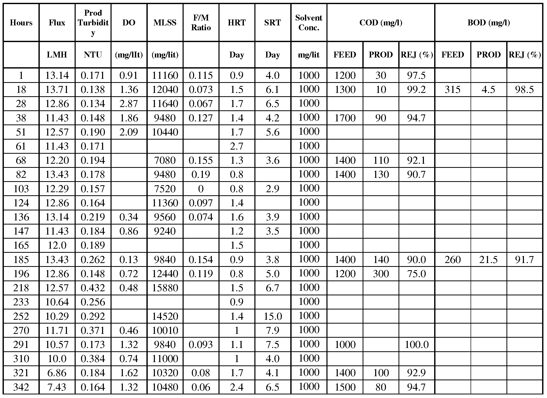
- High MLSS (mixed liquid suspended solid) and low HRT (hydraulic retention time) of a membrane bioreactor enhances the treatment process and rejects 90-95% of COD & BOD generated by the organic contaminants.
- Solvent concentration as high as 0.10% has been successfully tested in laboratory MBR units under high MLSS conditions. About 10,000 to 15,000 mg/1 active solids were maintained in the bioreactor. Hydraulic retention time (HRT) was maintained at more or less than a day.
- COD & BOD values as high as 1500 mg/1 & 500 mg/1 created by the presence of solvent could be degraded in the system and produce RO feed grade water. Given below a summarized operational & analytical data of the small laboratory bioreactor trial, which was conducted for about 500 hours. Table- VIII
Abstract
Description


Claims
Priority Applications (4)
| Application Number | Priority Date | Filing Date | Title |
|---|---|---|---|
| EP09763502A EP2285475A4 (en) | 2008-06-10 | 2009-06-10 | Preparation of high performance ultra filtration hollow fiber membrane |
| AU2009257503A AU2009257503A1 (en) | 2008-06-10 | 2009-06-10 | Preparation of high performance ultra filtration hollow fiber membrane |
| CA2727673A CA2727673A1 (en) | 2008-06-10 | 2009-06-10 | Preparation of high performance ultra filtration hollow fiber membrane |
| CN2009801270611A CN102089070A (en) | 2008-06-10 | 2009-06-10 | Preparation of high performance ultra filtration hollow fiber membrane |
Applications Claiming Priority (2)
| Application Number | Priority Date | Filing Date | Title |
|---|---|---|---|
| IN1369/DEL/2008 | 2008-06-10 | ||
| IN1369DE2008 | 2008-06-10 |
Publications (1)
| Publication Number | Publication Date |
|---|---|
| WO2009152212A1 true WO2009152212A1 (en) | 2009-12-17 |
Family
ID=41413791
Family Applications (1)
| Application Number | Title | Priority Date | Filing Date |
|---|---|---|---|
| PCT/US2009/046851 WO2009152212A1 (en) | 2008-06-10 | 2009-06-10 | Preparation of high performance ultra filtration hollow fiber membrane |
Country Status (6)
| Country | Link |
|---|---|
| US (2) | US8104624B2 (en) |
| EP (1) | EP2285475A4 (en) |
| CN (1) | CN102089070A (en) |
| AU (1) | AU2009257503A1 (en) |
| CA (1) | CA2727673A1 (en) |
| WO (1) | WO2009152212A1 (en) |
Families Citing this family (23)
| Publication number | Priority date | Publication date | Assignee | Title |
|---|---|---|---|---|
| WO2009152212A1 (en) * | 2008-06-10 | 2009-12-17 | Aquatech International Corporation | Preparation of high performance ultra filtration hollow fiber membrane |
| US9821105B2 (en) * | 2008-07-01 | 2017-11-21 | Baxter International Inc. | Nanoclay sorbents for dialysis |
| EP2335814B1 (en) * | 2008-09-26 | 2016-12-28 | Asahi Kasei Kabushiki Kaisha | Use of porous hollow-fiber membrane for producing clarified biomedical culture medium |
| TW201219480A (en) * | 2010-11-10 | 2012-05-16 | Far Eastern New Century Corp | Chlorinated polymer enhancing the wettability of silicone hydrogel, silicone hydrogel comprising the same and ocular article made therefrom |
| US20140157985A1 (en) * | 2011-05-03 | 2014-06-12 | University Of Mississippi | Dehumidification Systems and Methods Thereof |
| CN102688708B (en) * | 2012-05-24 | 2014-01-01 | 北京化工大学 | Method for separating aromatic hydrocarbon from alkane by ionic liquid and membrane process coupling technology |
| CN103882536B (en) * | 2012-12-19 | 2016-12-28 | 财团法人工业技术研究院 | Hollow fiber for adsorption or filtration and method for producing the same |
| US9222200B2 (en) | 2012-12-19 | 2015-12-29 | Industrial Technology Research Institute | Spinning device |
| CN107530640B (en) * | 2015-05-01 | 2020-10-30 | 沙特基础工业全球技术有限公司 | Method for producing porous asymmetric membranes, and associated membranes and separation modules |
| JP6641380B2 (en) * | 2015-09-30 | 2020-02-05 | 株式会社バイテク | Wastewater treatment carrier module, wastewater treatment carrier unit and wastewater treatment device |
| CN108277647A (en) * | 2017-01-06 | 2018-07-13 | 成都瑞沐生物医药科技有限公司 | Particulate matter barrier material and its application in haze |
| CN107740196A (en) * | 2017-10-12 | 2018-02-27 | 南京科技职业学院 | A kind of preparation method based on micro-fluidic doughnut |
| US20190233972A1 (en) | 2018-01-31 | 2019-08-01 | Saudi Arabian Oil Company | Producing Fibers Using Spinnerets |
| CN108479432B (en) * | 2018-02-08 | 2020-10-27 | 东华大学 | Preparation method of hydrophilic phenolphthalein polyether sulfone composite nanofiber ultrafiltration membrane |
| US10969124B2 (en) | 2018-09-13 | 2021-04-06 | University Of Mississippi | Vacuum sweep dehumidification system |
| CN109706547B (en) * | 2019-01-03 | 2020-08-25 | 西南交通大学 | Polymer fiber and preparation method thereof |
| CN109806779A (en) * | 2019-03-07 | 2019-05-28 | 道和矿冶科技(北京)有限公司 | A kind of preparation method of Polyethersulfone Hollow Fiber Plasma gas separation membrane |
| US11406941B2 (en) | 2020-02-14 | 2022-08-09 | Saudi Arabian Oil Company | Thin film composite hollow fiber membranes fabrication systems |
| US11253819B2 (en) | 2020-05-14 | 2022-02-22 | Saudi Arabian Oil Company | Production of thin film composite hollow fiber membranes |
| CN115253704B (en) * | 2021-04-29 | 2023-07-21 | 中国石油化工股份有限公司 | Hydrophobic polymer microfiltration membrane and preparation method and application thereof |
| CN115253705B (en) * | 2021-04-30 | 2023-11-03 | 苏州永沁泉智能设备有限公司 | Separation membrane with functional interface and preparation method and application thereof |
| CN113957703B (en) * | 2021-10-19 | 2023-11-03 | 浙江理工大学 | Beaded nanofiber material and preparation method thereof |
| CN114832638A (en) * | 2022-05-16 | 2022-08-02 | 山东威高血液净化制品股份有限公司 | Method and device for post-treating polymer membrane by utilizing sodium hypochlorite to regulate and control pore size of polymer membrane |
Citations (4)
| Publication number | Priority date | Publication date | Assignee | Title |
|---|---|---|---|---|
| US6355730B1 (en) * | 1995-06-30 | 2002-03-12 | Toray Industries, Inc. | Permselective membranes and methods for their production |
| US6416668B1 (en) * | 1999-09-01 | 2002-07-09 | Riad A. Al-Samadi | Water treatment process for membranes |
| US6596167B2 (en) * | 2001-03-26 | 2003-07-22 | Koch Membrane Systems, Inc. | Hydrophilic hollow fiber ultrafiltration membranes that include a hydrophobic polymer and a method of making these membranes |
| US7070721B2 (en) * | 2002-01-28 | 2006-07-04 | Koch Membrane Systems | Method of making and using a hollow fiber microfiltration membrane |
Family Cites Families (19)
| Publication number | Priority date | Publication date | Assignee | Title |
|---|---|---|---|---|
| US4051300A (en) | 1973-09-03 | 1977-09-27 | Gulf South Research Institute | Hollow synthetic fibers |
| US5683916A (en) * | 1988-10-31 | 1997-11-04 | Hemasure Inc. | Membrane affinity apparatus and purification methods related thereto |
| US5151227A (en) * | 1991-03-18 | 1992-09-29 | W. R. Grace & Co.-Conn. | Process for continuous spinning of hollow-fiber membranes using a solvent mixture as a precipitation medium |
| US5762798A (en) | 1991-04-12 | 1998-06-09 | Minntech Corporation | Hollow fiber membranes and method of manufacture |
| JP3232117B2 (en) * | 1991-11-19 | 2001-11-26 | 鐘淵化学工業株式会社 | Polysulfone porous hollow fiber |
| US5340480A (en) * | 1992-04-29 | 1994-08-23 | Kuraray Co., Ltd. | Polysulfone-based hollow fiber membrane and process for manufacturing the same |
| ES2237760T3 (en) | 1995-06-30 | 2005-08-01 | Toray Industries, Inc. | MANUFACTURING PROCEDURE OF A SEMIPERMEABLE MEMBRANE OF POLISHULPHONE HOLLOW FIBERS. |
| ES2181852T5 (en) * | 1995-06-30 | 2020-04-29 | Toray Industries | Selective permeability membranes and procedures for obtaining them |
| WO1997022405A1 (en) * | 1995-12-18 | 1997-06-26 | Asahi Kasei Kogyo Kabushiki Kaisha | Hollow fiber type filtration membrane |
| JP4211168B2 (en) * | 1999-12-21 | 2009-01-21 | 東レ株式会社 | Dialyzer manufacturing method and sterilization method |
| US6355720B1 (en) * | 2000-05-12 | 2002-03-12 | Johnson Polymer, Inc. | Latex formulations with reduced yellowing |
| JP3551971B1 (en) * | 2003-11-26 | 2004-08-11 | 東洋紡績株式会社 | Polysulfone permselective hollow fiber membrane |
| EP1658889A1 (en) * | 2004-11-19 | 2006-05-24 | "VLAAMSE INSTELLING VOOR TECHNOLOGISCH ONDERZOEK", afgekort "V.I.T.O." | Longitudinal reinforced self-supporting capillary membranes and method for manufacturing thereof |
| EP1710011A1 (en) * | 2005-04-07 | 2006-10-11 | Gambro Lundia AB | Filtration membrane |
| DE102005026804B3 (en) * | 2005-06-09 | 2007-02-22 | Membrana Gmbh | Microfiltration membrane with improved filtration behavior |
| ATE460974T1 (en) | 2006-07-07 | 2010-04-15 | Gambro Lundia Ab | PLASMA SEPARATION MEMBRANE |
| EP2190924B1 (en) * | 2007-09-06 | 2011-05-25 | Basf Se | Blends from branched polyaryl ethers and hydrophilic polymers |
| JP5504560B2 (en) * | 2007-10-19 | 2014-05-28 | 東洋紡株式会社 | Hollow fiber membrane for liquid processing |
| WO2009152212A1 (en) * | 2008-06-10 | 2009-12-17 | Aquatech International Corporation | Preparation of high performance ultra filtration hollow fiber membrane |
-
2009
- 2009-06-10 WO PCT/US2009/046851 patent/WO2009152212A1/en active Application Filing
- 2009-06-10 US US12/481,909 patent/US8104624B2/en active Active
- 2009-06-10 EP EP09763502A patent/EP2285475A4/en not_active Withdrawn
- 2009-06-10 CN CN2009801270611A patent/CN102089070A/en active Pending
- 2009-06-10 AU AU2009257503A patent/AU2009257503A1/en not_active Abandoned
- 2009-06-10 CA CA2727673A patent/CA2727673A1/en not_active Abandoned
-
2012
- 2012-01-20 US US13/354,664 patent/US8424688B2/en active Active
Patent Citations (4)
| Publication number | Priority date | Publication date | Assignee | Title |
|---|---|---|---|---|
| US6355730B1 (en) * | 1995-06-30 | 2002-03-12 | Toray Industries, Inc. | Permselective membranes and methods for their production |
| US6416668B1 (en) * | 1999-09-01 | 2002-07-09 | Riad A. Al-Samadi | Water treatment process for membranes |
| US6596167B2 (en) * | 2001-03-26 | 2003-07-22 | Koch Membrane Systems, Inc. | Hydrophilic hollow fiber ultrafiltration membranes that include a hydrophobic polymer and a method of making these membranes |
| US7070721B2 (en) * | 2002-01-28 | 2006-07-04 | Koch Membrane Systems | Method of making and using a hollow fiber microfiltration membrane |
Non-Patent Citations (1)
| Title |
|---|
| See also references of EP2285475A4 * |
Also Published As
| Publication number | Publication date |
|---|---|
| US8424688B2 (en) | 2013-04-23 |
| EP2285475A4 (en) | 2012-10-10 |
| CN102089070A (en) | 2011-06-08 |
| AU2009257503A1 (en) | 2009-12-17 |
| US20090308805A1 (en) | 2009-12-17 |
| US8104624B2 (en) | 2012-01-31 |
| US20120111790A1 (en) | 2012-05-10 |
| CA2727673A1 (en) | 2009-12-17 |
| EP2285475A1 (en) | 2011-02-23 |
Similar Documents
| Publication | Publication Date | Title |
|---|---|---|
| US8424688B2 (en) | Preparation of high performance ultra filtration hollow fiber membrane | |
| AU2009297565B2 (en) | Porous membrane, process for producing porous membrane, process for producing clarified liquid, and porous-membrane module | |
| CN100417434C (en) | Process for preparing composite hollow fiber membrane | |
| DK2922620T3 (en) | Process for the preparation of integral asymmetric hollow fiber polymer membrane consisting of amphiphilic block copolymer, the hollow fiber membrane obtained and use thereof | |
| EP3147024A1 (en) | Hollow-fibre polymer membrane | |
| EP3023138A1 (en) | Hydrophilised vinylidene fluoride-based porous hollow fibre membrane, and manufacturing method therefor | |
| WO2010029908A1 (en) | Hollow-fiber membrane and process for production of hollow-fiber membrane | |
| WO2017217446A1 (en) | Porous membrane, and method for manufacturing porous membrane | |
| CN1253241C (en) | Manufacture and products of hollow fiber membrane of outer pressured polyvinylidene fluoride by immersion gelation | |
| US20010047959A1 (en) | Polyacrylonitrile-based filtration membrane in a hollow fiber state | |
| KR100536643B1 (en) | Method for preparation of chemical, microorganism and fouling resistant asymmetric ultrafiltration and microfiltration membranes by blending titania nano particle | |
| JP3317975B2 (en) | Polyacrylonitrile hollow fiber filtration membrane | |
| EP2004748A1 (en) | Hollow fiber membrane and preparing method thereof | |
| KR20160079354A (en) | Composition of PVDF porous hollow fiber membrane improved with hydrophilicity and PVDF porous hollow fiber membrane having asymmetry sandwich structure using the same | |
| WO2022249839A1 (en) | Separation membrane and method for producing same | |
| KR20130040623A (en) | The preparation method of hollow fiber membrane with high permeation using hydrophilic polyvinylidenefluoride composites for water treatment | |
| JP2675197B2 (en) | Manufacturing method of high strength and porous polysulfone hollow fiber membrane | |
| WO2019172077A1 (en) | Hollow-fiber membrane and method for producing hollow-fiber membrane | |
| Yuliwati et al. | Morphological and Permeability Fraction of Mixed Matrix Polysulfone Membrane on Batik Palembang Wastewater Treatment | |
| JPH10337456A (en) | Membrane forming stock solution | |
| JPS63100902A (en) | Aromatic polysulfone hollow yarn membrane and its manufacture | |
| JPH11244675A (en) | Production of membrane | |
| KR20010003232A (en) | A polysulfone based hollow fiber membrane for hemodialysis and preparing process for the same | |
| Basri et al. | Effect of different incorporation route on the properties of polyethersulfone‐silver membrane | |
| Yuliwati et al. | Refinery Produced Wastewater Treatment by PVDF Composite Hollow Fiber Membrane |
Legal Events
| Date | Code | Title | Description |
|---|---|---|---|
| WWE | Wipo information: entry into national phase |
Ref document number: 200980127061.1 Country of ref document: CN |
|
| 121 | Ep: the epo has been informed by wipo that ep was designated in this application |
Ref document number: 09763502 Country of ref document: EP Kind code of ref document: A1 |
|
| WWE | Wipo information: entry into national phase |
Ref document number: 2009763502 Country of ref document: EP |
|
| WWE | Wipo information: entry into national phase |
Ref document number: 2009257503 Country of ref document: AU Ref document number: 2727673 Country of ref document: CA |
|
| NENP | Non-entry into the national phase |
Ref country code: DE |
|
| ENP | Entry into the national phase |
Ref document number: 2009257503 Country of ref document: AU Date of ref document: 20090610 Kind code of ref document: A |