以下、図面を参照しつつ、本発明の実施の形態について説明する。以下の説明では、同一の部分には同一の符号を付してある。それらの名称および機能も同じである。したがってそれらについての詳細な説明は繰り返さない。
Hereinafter, embodiments of the present invention will be described with reference to the drawings. In the following description, the same parts are denoted by the same reference numerals. Their names and functions are also the same. Therefore, detailed description about them will not be repeated.
[第1の実施の形態]
(構成の概略)
図1を参照して、第1の実施の形態に係るX線検査装置100の構成について説明する。図1は、第1の実施の形態に係るX線検査装置100の概略ブロック図である。
First Embodiment
(Outline of configuration)
The configuration of the X-ray inspection apparatus 100 according to the first embodiment will be described with reference to FIG. FIG. 1 is a schematic block diagram of an X-ray inspection apparatus 100 according to the first embodiment.
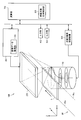
X線検査装置100は、X線18を出力するX線源10と、X線検出器23と、画像取得制御機構30とを備える。さらに、X線検査装置100は、入力部40と、出力部50と、X線源制御機構60と、演算部70と、メモリ90とを備える。
The X-ray inspection apparatus 100 includes an X-ray source 10 that outputs an X-ray 18, an X-ray detector 23, and an image acquisition control mechanism 30. Furthermore, the X-ray inspection apparatus 100 includes an input unit 40, an output unit 50, an X-ray source control mechanism 60, an arithmetic unit 70, and a memory 90.
X線源10とX線検出器23との間には検査対象1が配置される。本実施においては、検査対象1は、部品が実装された回路基板であるとする。なお、図1では、下から順にX線源10、検査対象1、X線検出器23が設置されているが、X線源の保守性の観点より、下から順に、X線検出器23、検査対象1、X線源10との並びでこれらを配置してもよい。
An inspection object 1 is disposed between the X-ray source 10 and the X-ray detector 23. In the present embodiment, the inspection target 1 is a circuit board on which components are mounted. In FIG. 1, the X-ray source 10, the inspection object 1, and the X-ray detector 23 are installed in order from the bottom, but from the viewpoint of the maintainability of the X-ray source, the X-ray detector 23, These may be arranged in line with the inspection object 1 and the X-ray source 10.
X線源10は、X線源制御機構60によって制御され、検査対象1に対して、X線18を照射する。本実施の形態では、検査対象1は、回路部品を実装した基板であるものとする。
The X-ray source 10 is controlled by the X-ray source control mechanism 60 to irradiate the inspection object 1 with X-rays 18. In the present embodiment, the inspection target 1 is a substrate on which circuit components are mounted.
検査対象1は、検査対象駆動機構20(図1には図示せず)により移動される。検査対象駆動機構20としては、例えば、X-Y-Zステージや、検査対象1を挟む1対のレールを用いることができる。
The inspection target 1 is moved by the inspection target drive mechanism 20 (not shown in FIG. 1). As the inspection target drive mechanism 20, for example, an XY stage or a pair of rails sandwiching the inspection target 1 can be used.
X線検出器23は、X線源10から出力され、検査対象1を透過したX線を検出して画像化する2次元X線検出器である。すなわち、X線検出器23は、検出されたX線が示す画像からを出力する。X線検出器23としては、I.I.(Image Intensifier)管や、FPD(フラットパネルディテクタ)を用いることができる。設置スペースの観点からは、X線検出器23には、FPDを用いることが望ましい。また、インライン検査で使うことができるようにX線検出器23は、高感度であることが望ましく、CdTeを使った直接変換方式のFPDであることが特に望ましい。
The X-ray detector 23 is a two-dimensional X-ray detector that detects and images X-rays output from the X-ray source 10 and transmitted through the inspection target 1. That is, the X-ray detector 23 outputs an image represented by the detected X-ray. As the X-ray detector 23, I.I. I. A tube (Image Intensifier) or an FPD (flat panel detector) can be used. From the viewpoint of installation space, it is desirable to use an FPD as the X-ray detector 23. Further, it is desirable that the X-ray detector 23 have high sensitivity so that it can be used in in-line inspection, and it is particularly desirable that the X-ray detector 23 be a direct conversion FPD using CdTe.
画像取得制御機構30は、画像データ取得部34を含む。画像データ取得部34は、演算部70から指定されたX線検出器23の画像データを取得する。
The image acquisition control mechanism 30 includes an image data acquisition unit 34. The image data acquisition unit 34 acquires the image data of the X-ray detector 23 specified by the calculation unit 70.
入力部40は、ユーザからの指示入力等を受け付けるための操作入力機器である。出力部50は、測定結果等を外部に出力する装置である。本実施の形態では、出力部50は、演算部70で構成されたX線画像等を表示するためのディスプレイである。
The input unit 40 is an operation input device for receiving an instruction input from a user. The output unit 50 is a device that outputs measurement results and the like to the outside. In the present embodiment, the output unit 50 is a display for displaying an X-ray image or the like configured by the calculation unit 70.
すなわち、ユーザは、入力部40を介して様々な入力を実行することができ、演算部70の処理によって得られる種々の演算結果が出力部50に表示される。出力部50に表示される画像は、ユーザによる目視の良否判定のために出力されてもよいし、あるいは、後で説明する良否判定部78の良否判定結果として出力されてもよい。
That is, the user can execute various inputs via the input unit 40, and various calculation results obtained by the processing of the calculation unit 70 are displayed on the output unit 50. The image displayed on the output unit 50 may be output for determination of the quality of visual inspection by the user, or may be output as a result of quality determination of the quality determination unit 78 described later.
X線源制御機構60は、電子ビームの出力を制御する電子ビーム制御部62を含む。電子ビーム制御部62は、演算部70から、X線焦点位置、X線エネルギー(管電圧、管電流)の指定を受ける。指定されるX線エネルギーは、検査対象の構成によって異なる。
The X-ray source control mechanism 60 includes an electron beam control unit 62 that controls the output of the electron beam. The electron beam control unit 62 receives designation of the X-ray focal position and the X-ray energy (tube voltage, tube current) from the computing unit 70. The designated X-ray energy differs depending on the configuration of the examination object.
演算部70は、メモリ90に格納されたプログラム96を実行して各部を制御し、また、所定の演算処理を実施する。演算部70は、X線源制御部72と、画像取得制御部74と、再構成部76と、良否判定部78と、検査対象位置制御部80と、X線焦点位置計算部82と、撮像条件設定部84とを含む。
The arithmetic unit 70 executes the program 96 stored in the memory 90 to control each unit, and performs predetermined arithmetic processing. The calculation unit 70 includes an X-ray source control unit 72, an image acquisition control unit 74, a reconstruction unit 76, a quality determination unit 78, an inspection target position control unit 80, an X-ray focal position calculation unit 82, and imaging. And a condition setting unit 84.
X線源制御部72は、X線焦点位置、X線エネルギーを決定し、X線源制御機構60に指令を送る。
The X-ray source control unit 72 determines the X-ray focal position, the X-ray energy, and sends a command to the X-ray source control mechanism 60.
画像取得制御部74は、X線検出器23が画像を取得するように、画像取得制御機構30に指令を送る。また、画像取得制御部74は、画像取得制御機構30から、画像データを取得する。
The image acquisition control unit 74 sends an instruction to the image acquisition control mechanism 30 so that the X-ray detector 23 acquires an image. Further, the image acquisition control unit 74 acquires image data from the image acquisition control mechanism 30.
再構成部76は、画像取得制御部74により取得された複数の画像データから3次元データを再構成する。
The reconstruction unit 76 reconstructs three-dimensional data from the plurality of image data acquired by the image acquisition control unit 74.
良否判定部78は、再構成部76により再構成された3次元データ、あるいは、透視データをもとに検査対象の良否を判定する。たとえば、良否判定部78は、半田ボールの形状を認識し、認識された形状が予め定められた許容範囲内であるか否かを判定する等により良否判定を行なう。なお、良否判定を行なうアルゴリズム、あるいは、アルゴリズムへの入力情報は、検査対象によって異なるため、良否判定部78は、これらを撮像条件情報94から入手する。
The quality determination unit 78 determines the quality of the inspection target based on the three-dimensional data reconstructed by the reconstruction unit 76 or the fluoroscopic data. For example, the quality determination unit 78 recognizes the shape of the solder ball, and performs the quality determination by determining whether the recognized shape is within a predetermined allowable range. Since the algorithm for performing the quality determination or the input information to the algorithm differs depending on the inspection target, the quality determination unit 78 obtains these from the imaging condition information 94.
検査対象位置制御部80は、検査対象駆動機構20を制御する。
X線焦点位置計算部82は、検査対象1のある検査エリアを検査する際に、その検査エリアに対するX線焦点位置や照射角などを計算する。
The inspection target position control unit 80 controls the inspection target drive mechanism 20.
When the X-ray focal position calculation unit 82 inspects a certain inspection area of the inspection object 1, the X-ray focal position calculation unit 82 calculates an X-ray focal position, an irradiation angle and the like with respect to the inspection area.
撮像条件設定部84は、検査対象1に応じて、X線源10からX線を出力する際の条件(たとえば、X線源に対する印加電圧、撮像時間等)を設定する。
The imaging condition setting unit 84 sets conditions (for example, voltage applied to the X-ray source, imaging time, and the like) when the X-ray source 10 outputs X-rays according to the inspection target 1.
メモリ90は、X線焦点位置情報92と、撮像条件情報94と、上述した演算部70が実行する各機能を実現するためのプログラム96と、X線検出器23が撮像した画像データ98とを含む。X線焦点位置情報92には、X線焦点位置計算部82によって計算されたX線焦点位置が含まれる。撮像条件情報94は、撮像条件設定部84によって設定された撮像条件や、良否判定を行なうアルゴリズムに関する情報を含む。
The memory 90 includes X-ray focal position information 92, imaging condition information 94, a program 96 for realizing each function executed by the arithmetic unit 70 described above, and image data 98 imaged by the X-ray detector 23. Including. The X-ray focal position information 92 includes the X-ray focal position calculated by the X-ray focal position calculation unit 82. The imaging condition information 94 includes information regarding an imaging condition set by the imaging condition setting unit 84 and an algorithm for determining the quality.
なお、メモリ90は、データを蓄積することができるものであればよい。メモリ90は、例えば、RAM(Random Access Memory)やEEPROM(Electrically Erasable and Programmable Read-Only Memory)やHDD(Hard Disc Drive)等の記憶装置により構成される。
Memory 90 should just be a thing which can accumulate data. The memory 90 is configured by, for example, a storage device such as a random access memory (RAM), an electrically erasable and programmable read-only memory (EEPROM), or a hard disc drive (HDD).
(具体的構成)
第1の実施の形態に係るX線検査装置100の具体的構成について、図2を参照して説明する。図2は、第1の実施の形態に係るX線検査装置100の構成を説明するための図である。なお、図2において、図1と同一部分には、同一符号を付している。また、図2では、図1に示した部分のうち、X線焦点位置の制御、X線検出器位置の制御、検査対象位置の制御等に直接関係し、説明に必要な部分を抜き出して記載している。
(Specific configuration)
The specific configuration of the X-ray inspection apparatus 100 according to the first embodiment will be described with reference to FIG. FIG. 2 is a diagram for explaining the configuration of the X-ray inspection apparatus 100 according to the first embodiment. In FIG. 2, the same parts as in FIG. 1 are given the same reference numerals. Further, in FIG. 2, among the portions shown in FIG. 1, portions directly related to the control of the X-ray focal position, the control of the X-ray detector position, the control of the inspection target position, etc. doing.
X線源10は、本実施の形態では、X線を発生する位置(X線焦点位置)を一方向に沿う可能な、走査型X線源である。X線源10は、X線源制御機構60を通した演算部70
からの命令に従って、X線を発生させる。
In the present embodiment, the X-ray source 10 is a scanning X-ray source capable of extending the position (X-ray focal position) for generating X-rays in one direction. The X-ray source 10 is a computing unit 70 passing through the X-ray source control mechanism 60.
X-rays are generated according to the instruction from.
ここで、図3を参照して、X線源10の構成について説明する。図3は、X線源10の断面図である。
Here, the configuration of the X-ray source 10 will be described with reference to FIG. FIG. 3 is a cross-sectional view of the X-ray source 10.
図3を参照して、X線源10においては、電子ビーム制御部62によって制御された電子銃19から、タングステンなどのターゲット11に対し電子ビーム16が照射される。そして、電子ビーム16がターゲットに衝突した場所(X線焦点位置17)からX線18が発生し、放射(出力)される。図3を参照して分かるように、X線源10は電子ビームの透過方向にX線を出力する、透過型のX線源である。
Referring to FIG. 3, in the X-ray source 10, an electron beam 16 is emitted from an electron gun 19 controlled by an electron beam control unit 62 to a target 11 such as tungsten. Then, an X-ray 18 is generated and emitted (outputted) from the position (X-ray focal position 17) where the electron beam 16 collides with the target. As can be seen with reference to FIG. 3, the X-ray source 10 is a transmissive X-ray source that outputs X-rays in the transmission direction of the electron beam.
なお、電子ビーム系は、真空容器9の中に収められている。真空容器9の内部は、真空ポンプ15によって真空に保たれており、電子銃19から高圧電源14によって加速された電子ビーム16が発射される。
The electron beam system is housed in a vacuum vessel 9. The inside of the vacuum vessel 9 is kept vacuum by a vacuum pump 15, and an electron beam 16 accelerated by a high voltage power source 14 is emitted from an electron gun 19.
X線源10は、電子線収束コイル13により収束された後、偏向ヨーク12によって電子ビーム16を偏向することにより、電子ビーム16がターゲット11に衝突する場所を変更することができる。たとえば、偏向ヨーク12によって偏向された電子ビーム16aはターゲット11に衝突し、X線焦点位置17aからX線18aが出力される。また、同様に、偏向ヨーク12によって偏向された電子ビーム16bはターゲット11に衝突し、X線焦点位置17bからX線18bが出力される。
The X-ray source 10 can be changed in position where the electron beam 16 collides with the target 11 by deflecting the electron beam 16 by the deflection yoke 12 after being converged by the electron beam focusing coil 13. For example, the electron beam 16a deflected by the deflection yoke 12 strikes the target 11, and an X-ray 18a is output from the X-ray focal position 17a. Similarly, the electron beam 16b deflected by the deflection yoke 12 collides with the target 11, and an X-ray 18b is output from the X-ray focal position 17b.
ターゲット11は、直線状のターゲットでもよいし、連続面のターゲットでもよい。連続面のターゲットを有する場合、X線源10は、X線焦点位置17を、ターゲット内の範囲で自由に設定できる。本撮像方法にこのX線源10を用いる場合には、X線焦点位置17を一方向に制限すればよい。また、図3で示したX線源10は透過型であるが、X線源10は、反射型でもよい。
The target 11 may be a linear target or a continuous surface target. When having a continuous surface target, the X-ray source 10 can freely set the X-ray focal position 17 within the range of the target. When this X-ray source 10 is used in the present imaging method, the X-ray focal position 17 may be limited to one direction. Moreover, although the X-ray source 10 shown in FIG. 3 is a transmission type, the X-ray source 10 may be a reflection type.
なお、X線焦点位置を移動させるには、たとえば、X線源自体の位置を、その都度、機械的に移動させることも可能である。ただし、走査型X線源を用いれば、X線焦点位置を移動させるにあたり、一定の範囲内であれば、X線源10を機械的に移動させることを必要とせず、保守性や信頼性に優れたX線検査装置を実現できる。また、走査型X線源によるX線走査は、機械的な走査に比べ、所要時間が100分の1程度で済む(線源による走査時間は数msであり、機械的な移動は、数100ms)。そのため、本実施の形態では、走査型X線源を用いる。なお、X線源としては、X線放射面上でX線発生位置を瞬時に変更することができる他の種類の線源、例えば、多焦点X線源を用いてもよい。
In order to move the X-ray focal position, for example, it is also possible to mechanically move the position of the X-ray source itself each time. However, if a scanning X-ray source is used, it is not necessary to move the X-ray source 10 mechanically within a certain range when moving the X-ray focal point position, for maintainability and reliability. An excellent X-ray inspection apparatus can be realized. In addition, X-ray scanning with a scanning X-ray source requires about 100 times shorter than mechanical scanning (scanning time with a radiation source is several ms, and mechanical movement is several hundred ms). ). Therefore, in the present embodiment, a scanning X-ray source is used. As the X-ray source, other types of radiation sources capable of instantaneously changing the X-ray generation position on the X-ray radiation surface, for example, a multifocal X-ray source may be used.
図2に戻って、検査対象駆動機構20は、アクチュエータと検査対象を固定する機構とを備える。検査対象駆動機構20は、演算部70内の検査対象位置制御部80に制御される検査対象位置駆動機構により、上記X線検出器23.1または23.2とは独立に、検査対象の視野を、XY方向に移動可能である。
Returning to FIG. 2, the inspection target drive mechanism 20 includes an actuator and a mechanism for fixing the inspection target. The inspection object drive mechanism 20 controls the inspection object position drive mechanism controlled by the inspection object position control unit 80 in the arithmetic unit 70, and the visual field of the inspection object independently of the X-ray detector 23.1 or 23.2. Can be moved in the XY directions.
インライン検査の際には、検査対象駆動機構20は、基本的に、検査対象1をY方向に移動する。つまり、検査対象駆動機構20は、未検査の検査対象1を-Y(+Yでも構わない)方向から+Y方向に移動して、X線の照射範囲まで運ぶ。また、検査対象駆動機構20は、検査が終了した検査対象1を、さらに+Y方向に移動する。
At the time of in-line inspection, the inspection target drive mechanism 20 basically moves the inspection target 1 in the Y direction. That is, the inspection target drive mechanism 20 moves the inspection target 1 which has not been inspected from the -Y (or + Y may be) direction to the + Y direction and carries it to the X-ray irradiation range. In addition, the inspection target drive mechanism 20 further moves the inspection target 1 whose inspection has been completed in the + Y direction.
検査対象駆動機構20としては、X線を妨げない装置を用いることが好ましい。本実施の形態では、検査対象駆動機構20として、検査対象1をその両端から挟むレール25aおよびレール25bを用いている。
It is preferable to use an apparatus that does not interfere with X-rays as the inspection target drive mechanism 20. In the present embodiment, as the inspection target drive mechanism 20, the rails 25a and the rails 25b sandwiching the inspection target 1 from both ends thereof are used.
演算部70は、検出器駆動制御部32、画像データ取得部34、走査X線源制御機構60に命令を送り、後に説明するような検査処理のためのフローチャートで示されるプログラムを実行する。
The calculation unit 70 sends an instruction to the detector drive control unit 32, the image data acquisition unit 34, and the scanning X-ray source control mechanism 60, and executes the program shown in the flowchart for the inspection process as described later.
特に、演算部70は、検出器駆動制御部32を通した命令により指示されるタイミングでX線透視画像の取得および撮像データの転送を行なう。また、演算部70は、入力部40からの入力によって検査装置の動作を制御し、各部の状態、または検査結果を出力部50より出力することができる。
In particular, the calculation unit 70 performs acquisition of an X-ray fluoroscopic image and transfer of imaging data at a timing instructed by an instruction through the detector drive control unit 32. In addition, the arithmetic unit 70 can control the operation of the inspection apparatus according to the input from the input unit 40, and can output the state of each unit or the inspection result from the output unit 50.
(撮像方式)
ここからは、X線検査装置100を用いたX線透視画像の撮像方式について説明する。
(Imaging method)
From here, the imaging method of the X-ray fluoroscopic image using the X-ray inspection apparatus 100 is demonstrated.
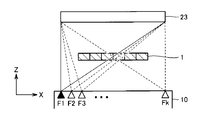
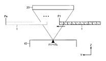
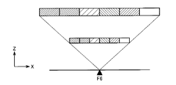
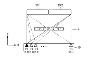
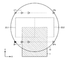
まず、図4から図6を用いて、X線検出器23、検査対象1、および、X線焦点位置17の位置関係について説明する。図4は、X線検出器23、検査対象1、および、X線焦点位置17をY方向から見た正面図である。図5は、X線検出器23、検査対象1、および、X線焦点位置17をZ方向から見た上面図である。図6は、X線検出器23、検査対象1、および、X線焦点位置17をX方向から見た側面図である。
First, the positional relationship between the X-ray detector 23, the inspection target 1, and the X-ray focal position 17 will be described with reference to FIGS. 4 to 6. FIG. 4 is a front view of the X-ray detector 23, the inspection target 1, and the X-ray focal position 17 as viewed from the Y direction. FIG. 5 is a top view of the X-ray detector 23, the inspection target 1, and the X-ray focal position 17 as viewed from the Z direction. FIG. 6 is a side view of the X-ray detector 23, the inspection target 1, and the X-ray focal position 17 as viewed from the X direction.
図4~6では、X線検出器23の位置を示している。しかしながら、X線検出に関係するのは、X線検出器23の有感エリア(受光部)であるので、各図に示したX線検出器23は、受光部と置き換えて考えてよい。図5を参照して、X線検出器23は、正方形、またはそれに近いアスペクト比の受光部を有する。
4 to 6 show the position of the X-ray detector 23. However, since the sensing area (light receiving unit) of the X-ray detector 23 relates to X-ray detection, the X-ray detector 23 shown in each drawing may be considered as a light receiving unit. Referring to FIG. 5, the X-ray detector 23 has a square or a light receiving unit with an aspect ratio close thereto.
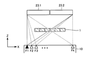
図4を参照して、X線検出器23は、検査対象領域のX方向両端部について、必要な角度からの透過画像を取得できるサイズとする。なお、ここでは、検査対象1の全面が検査対象領域であるとしている。斜めCTのためには、X線検出器23のX方向長さは、検査対象1のX方向長さに比べ、長くなっている必要がある。
Referring to FIG. 4, the X-ray detector 23 has a size such that transmission images from necessary angles can be acquired at both ends in the X direction of the region to be inspected. Here, it is assumed that the entire surface of the inspection object 1 is the inspection object area. For oblique CT, the X-direction length of the X-ray detector 23 needs to be longer than the X-direction length of the inspection object 1.
また、図4を参照して、X線源10は、検査対象領域をX方向に移動させることなく、検査対象領域のX方向両端部を必要な角度から照射できるX線放射領域を持っている。X線源10は、X方向のライン上の互いに異なる複数の焦点位置(図においてF1~Fk)で、X線をZ方向に順次放射する。X線検出器23は、一照射毎に透過画像を取得する。
Further, referring to FIG. 4, X-ray source 10 has an X-ray radiation area capable of irradiating both ends in the X direction of the examination area from a required angle without moving the examination area in the X direction. . The X-ray source 10 sequentially emits X-rays in the Z direction at a plurality of different focal positions (F1 to Fk in the figure) on the line in the X direction. The X-ray detector 23 acquires a transmission image for each irradiation.
図5あるいは図6を参照して、X線検査装置100は、X線を焦点位置F1からFkのそれぞれで照射および撮像した後、検査対象1を位置P1からP2へY方向移動させて、F1~Fk照射および撮像を行なう。X線検査装置100は、同様に、X線照射と検査対象1の移動とを繰り返す。図6における位置Peで検査対象1の照射および撮像が終わると、CT撮像は終了となる。検査対象1が位置Peにあるとき、検査対象領域のY方向下端を透過したX線検出器23に入射する。
5 or 6, X-ray inspection apparatus 100 irradiates and picks up X-rays at focal positions F1 to Fk, respectively, and then moves inspection object 1 from position P1 to P2 in the Y direction, and F1 Perform Fk irradiation and imaging. Similarly, the X-ray inspection apparatus 100 repeats X-ray irradiation and movement of the inspection object 1. When the irradiation and imaging of the inspection target 1 are completed at the position Pe in FIG. 6, the CT imaging is completed. When the inspection target 1 is at the position Pe, it enters the X-ray detector 23 that has passed through the lower end of the inspection target area in the Y direction.
X線検査装置100は、検査対象領域を複数の領域(部分領域)に分割して撮像画像を管理する。すなわち、X線検査装置100は、撮像画像のうち、各部分領域に対応する画像(部分画像とよぶ)を取得し、部分画像から、部分領域の3次元データを再構成する。以下、このことについて説明する。
The X-ray inspection apparatus 100 divides the inspection target area into a plurality of areas (partial areas) to manage the captured image. That is, the X-ray inspection apparatus 100 acquires an image (referred to as a partial image) corresponding to each partial region in the captured image, and reconstructs three-dimensional data of the partial region from the partial image. This will be described below.
図7は、検査対象1の斜視図である。検査対象1は、X方向およびY方向に分割されている。ここでは、検査対象1をXY方向のそれぞれについて6方向、したがって、36方向から撮像することを考える。そのためには、X方向について、6方向からX線を照射するために、図7に示すように検査対象1をX方向について6等分割して取り扱うことが望ましい。Y方向については、X方向についての分割と等しい長さで分割する。その結果、図7に示す例では、検査対象1は、X方向に6分割、Y方向に10分割されている。
FIG. 7 is a perspective view of the inspection object 1. The inspection target 1 is divided in the X direction and the Y direction. Here, it is considered that the inspection object 1 is imaged from six directions, that is, 36 directions in each of the X and Y directions. For that purpose, in order to irradiate X-rays from six directions in the X direction, it is desirable to handle the inspection object 1 equally divided in six in the X direction as shown in FIG. The Y direction is divided at a length equal to the division in the X direction. As a result, in the example illustrated in FIG. 7, the inspection target 1 is divided into six in the X direction and ten in the Y direction.
図8は、部分領域を透過するX線について説明するための図である。図8では、構成をXZ平面から見ている。X線検査装置100は、焦点F1~F11において撮像を実施し、各焦点について、X線透過画像を取得する。
FIG. 8 is a diagram for describing X-rays transmitted through a partial region. In FIG. 8, the configuration is viewed from the XZ plane. The X-ray inspection apparatus 100 performs imaging at the focal points F1 to F11, and acquires an X-ray transmission image for each focal point.
焦点位置F1からのX線は、検査対象1の左端の部分領域に入射し、X線検出器23に入射する。焦点位置F1からの点線は、右方向に最大角度で放射したX線を示す。なお、焦点位置F1からは、左方向にもX線が出力するが、図8では、このX線は図示していない。
The X-ray from the focal position F1 is incident on the left end partial region of the inspection object 1 and is incident on the X-ray detector 23. The dotted line from the focal position F1 indicates the X-ray emitted at the maximum angle in the right direction. Although X-rays are also output in the left direction from the focal position F1, these X-rays are not shown in FIG.
焦点位置F2については、X線検出器23は、左端の部分領域およびその隣の部分領域について透過像を取得することができる。焦点位置F3~F11についても、1つまたは複数の部分領域について透過像を取得できる。
For the focal position F2, the X-ray detector 23 can acquire transmission images of the partial region at the left end and the partial region next to it. For focal positions F3 to F11, transmission images can be acquired for one or more partial regions.
その結果、検査対象1の左端の部分領域には、焦点位置F1~F6から出たX線が透過し、透過したX線がX線検出器23に入射する。検査対象1の右端の部分領域には、焦点位置F6~F11から出たX線が透過し、透過したX線がX線検出器23に入射する。同様に、いずれの部分領域にも、6つの焦点位置から出たX線が透過し、透過したX線がX線検出器23に入射する。そのためF1~F11での撮像で、6つの視野について6方向からの撮像が完了していることとなる。
As a result, the X-rays emitted from the focal positions F1 to F6 are transmitted to the left end partial region of the inspection object 1, and the transmitted X-rays enter the X-ray detector 23. The X-rays emitted from the focal positions F6 to F11 are transmitted to the partial region at the right end of the inspection object 1, and the transmitted X-rays enter the X-ray detector 23. Similarly, X-rays emitted from the six focal positions are transmitted to any partial region, and the transmitted X-rays enter the X-ray detector 23. Therefore, in the imaging in F1 to F11, imaging from six directions is completed for six fields of view.
なお、X線を放射させるX方向の距離間隔は、図7で示すX方向の分割ステップと同じ距離が望ましい。ただし、距離間隔は、これに限られるわけではない。
In addition, as for the distance interval of the X direction which radiates X-ray, the same distance as the division | segmentation step of the X direction shown in FIG. 7 is desirable. However, the distance interval is not limited to this.
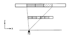
部分画像について、図9~図11を参照して説明する。図9~図11は、それぞれ、焦点位置F1,F3,F6について取得される部分画像を示す図である。
The partial image will be described with reference to FIGS. 9 to 11. 9 to 11 show partial images obtained for the focal positions F1, F3 and F6, respectively.
図9を参照して、焦点位置F1からX線が出力する場合、X線検査装置100は、左端の部分領域についての部分画像を得る。図では、検査対象1の部分領域と、部分領域が写っているX線検出器23上の位置を、同一のハッチングで示している。
Referring to FIG. 9, when an X-ray is output from focal position F1, X-ray inspection apparatus 100 obtains a partial image of the left partial region. In the figure, the partial area of the inspection object 1 and the position on the X-ray detector 23 where the partial area is shown are indicated by the same hatching.
具体的には、画像取得制御部74は、焦点位置、検査対象1の位置、部分領域のサイズ、X線検出器23の位置に基づいて、焦点位置F1を出力し、左端の部分領域を透過したX線が入射するX線検出器23内の領域を求める。画像取得制御部74は、X線検出器23が求めた領域の画像を取得するように、画像取得制御機構30に指令を送る。画像取得制御部74は、その結果、取得された画像を部分画像として、メモリ90に格納する。あるいは、画像取得制御部74は、X線検出器23が取得した、検出面全体の画像から、求めた領域内の画像を部分画像として抽出してもよい。
Specifically, the image acquisition control unit 74 outputs the focal position F1 based on the focal position, the position of the inspection object 1, the size of the partial area, and the position of the X-ray detector 23, and transmits the left partial area A region in the X-ray detector 23 on which the X-rays enter is determined. The image acquisition control unit 74 sends a command to the image acquisition control mechanism 30 so as to acquire an image of the area obtained by the X-ray detector 23. As a result, the image acquisition control unit 74 stores the acquired image as a partial image in the memory 90. Alternatively, the image acquisition control unit 74 may extract an image within the determined area as a partial image from the image of the entire detection surface acquired by the X-ray detector 23.
同様に、図10を参照して、焦点位置F3からX線が出力する場合、X線検査装置100は、3つの部分領域についての部分画像を得る。
Similarly, referring to FIG. 10, when an X-ray is output from focal position F3, X-ray inspection apparatus 100 obtains partial images of three partial regions.
図11を参照して、焦点位置F6からX線が出力する場合、X線検査装置100は、6つの部分領域についての部分画像を得る。
Referring to FIG. 11, when X-rays are output from focal position F6, X-ray inspection apparatus 100 obtains partial images of six partial regions.
図9~図11を参照して、1つの部分領域に着目すると、その部分領域がX線検出器23上にうつる位置は、焦点位置の移動に伴ってX方向に移動していくこととなる。
Referring to FIGS. 9 to 11, focusing on one partial area, the position at which the partial area shifts onto X-ray detector 23 moves in the X direction with the movement of the focal position. .
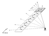
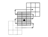
また、X線検査装置100は、検査対象1をY方向に移動することで、異なるY位置からのX線透視画像を撮像する。図12を参照して、検査対象1の移動について説明する。図12では、図7の部分領域2(図8の左端にある部分領域)の移動について示している。
Further, the X-ray inspection apparatus 100 captures X-ray fluoroscopic images from different Y positions by moving the inspection target 1 in the Y direction. The movement of the inspection object 1 will be described with reference to FIG. FIG. 12 shows the movement of the partial area 2 of FIG. 7 (the partial area at the left end of FIG. 8).
検査対象1をY方向に移動することで、部分領域2と、焦点位置(図12では、特に、F11を示している)とのY方向の位置関係が変わり、焦点位置F11から出力したX線の部分領域2への入射角度が変わる。この場合、部分領域2の位置を位置P1からP6まで5回移動するため、Y方向について6方向からのX線透視画像が撮像される。
By moving the inspection target 1 in the Y direction, the positional relationship in the Y direction between the partial region 2 and the focal position (in FIG. 12, particularly, F11 is shown) changes, and the X-ray output from the focal position F11 The incident angle to the partial area 2 of In this case, since the position of partial region 2 is moved five times from position P1 to position P6, an X-ray fluoroscopic image from six directions in the Y direction is captured.
一つ行を移動するたびに、焦点F1からF11で連続的に撮像が行われる。したがって、部分領域2には、位置P1~P6の各々において、焦点F6~F10からも、それぞれ異なる角度からのX線が照射される。その結果、P6での撮像を終えたときには、図13に示すように、36方向からの撮像が完了していることになる。図13は、部分領域2に入射するX線の入射方向を示す図である。
Every time one row is moved, imaging is performed continuously at the focal points F1 to F11. Therefore, in each of the positions P1 to P6, the partial regions 2 are irradiated with X-rays from different angles also from the focal points F6 to F10. As a result, when the imaging at P6 is finished, as shown in FIG. 13, imaging from 36 directions is completed. FIG. 13 is a view showing the incident direction of X-rays incident on the partial region 2.
部分領域2が位置P6で撮像されているとき、部分領域2の一つ後ろの行においては、位置P5での撮像が、二つ後ろの行においては位置P4での撮像、というように、後続の行も同時に撮像が行われている状態となる。よって、Y方向への移動とF1~F11照射を繰り返し、検査対象領域のY方向最終行が位置P6で撮像終了したときに、CT検査のための撮像が全域において完了したこととなる。このときの部分領域2の先端位置が、図6の位置Peである。
When the partial area 2 is imaged at the position P6, the imaging at the position P5 is subsequent to the partial area 2, and the imaging at the position P4 is subsequent to the two subsequent lines. The row of is also in the state where imaging is being performed simultaneously. Therefore, the movement in the Y direction and the F1 to F11 irradiation are repeated, and when the last line in the Y direction of the inspection target area has been imaged at the position P6, the imaging for CT examination is completed in the entire area. The tip position of the partial region 2 at this time is the position Pe of FIG.
上述のように、本実施の形態に係るX線検査装置100では、X線源10がX線焦点位置17から出力し、検査対象1の検査対象領域をX方向(第1の方向)について分割した複数の部分領域2をそれぞれ透過したX線の検出結果から、複数の部分領域2の各々についての部分画像を取得する。この部分画像の取得を、X線源10のX線焦点位置17をX方向に走査しながら繰り返すことで、複数のX線焦点位置17の各々における部分画像が得られる。
As described above, in the X-ray inspection apparatus 100 according to the present embodiment, the X-ray source 10 outputs from the X-ray focal position 17, and the inspection target area of the inspection object 1 is divided in the X direction (first direction). A partial image of each of the plurality of partial regions 2 is acquired from the detection result of the X-ray transmitted through each of the plurality of partial regions 2. By repeating the acquisition of the partial image while scanning the X-ray focal position 17 of the X-ray source 10 in the X direction, a partial image at each of the plurality of X-ray focal positions 17 is obtained.
さらに、X線源10のX線焦点位置17をX方向に走査した後に、対象物1をY方向(第2の方向)に移動させ、対象物1をY方向に移動した状態からX線源10のX線焦点位置17をX方向に走査しつつ、各X線焦点位置17における部分画像を順次取得する。
Furthermore, after scanning the X-ray focal position 17 of the X-ray source 10 in the X direction, the object 1 is moved in the Y direction (second direction), and the object 1 is moved in the Y direction. While scanning ten X-ray focal positions 17 in the X direction, partial images at each X-ray focal position 17 are sequentially acquired.
そして、この得られた各X線焦点位置17における部分画像から3次元データを再構成する。
Then, three-dimensional data is reconstructed from the partial image at each obtained X-ray focal position 17.
つまり、本実施の形態に係るX線検査装置100は、焦点走査により、複数のX方向の照射角度を、検査対象の機械移動で複数のY方向の照射角度を実現している。本方式によれば、多数の方向から検査対象を撮像するにあたって、検査対象を一方向(これまでの説明では、Y方向)にしか動かさなくてよい。したがって、従来の方法に比べ、検査対象の移動回数を削減できる。そのため、X線検査装置100によれば、高速に、検査対象全体について高精度な3次元データを再構成することができる。
That is, the X-ray inspection apparatus 100 according to the present embodiment realizes a plurality of irradiation angles in the X direction by focus scanning and a plurality of irradiation angles in the Y direction by mechanical movement of the inspection object. According to this method, when imaging an inspection object from multiple directions, the inspection object may be moved only in one direction (the Y direction in the above description). Therefore, compared with the conventional method, the number of movements of the inspection object can be reduced. Therefore, according to the X-ray inspection apparatus 100, highly accurate three-dimensional data can be reconstructed at high speed for the entire inspection object.
また、従来では、CT再構成のために必要な画像データを得るために、通常3つ以上の機械動作軸が必要とされていた。しかし、X線検査装置100において、機械動作軸は、1つでよく、構成が簡略である。
Also, conventionally, in order to obtain image data necessary for CT reconstruction, three or more machine operation axes are usually required. However, in the X-ray inspection apparatus 100, the number of machine operation axes may be one, and the configuration is simple.
さらに、検査対象1のY方向への1ステップ毎の移動距離と、検査対象1において設定される各部分領域の幅(X方向およびY方向はいずれも同じ値であるとする)とを一致させておけば、移動および撮像を繰り返して、CT検査のための撮像が全域において完了した時点で、撮像データを格納するコンピュータの中を、「検査対象である基板全面のn×n方向からの撮像データが集まっている」状態にできる。そのあと、撮像データを区切った小さな範囲で再構成するか、全面一度に再構成するか、興味領域のみを再構成するかは任意に選択できる。
Furthermore, the movement distance of the inspection object 1 in the Y direction for each step and the width of each partial area set in the inspection object 1 (the X direction and the Y direction both have the same value) are made to coincide with each other. If it is stored, the movement and imaging are repeated, and when imaging for CT examination is completed in the entire area, the inside of the computer storing the imaging data is “imaged from the n × n direction of the entire surface of the substrate to be inspected. It is possible to make the data gathered. After that, it is possible to arbitrarily select whether to reconstruct the imaging data in a small divided range, to reconstruct it all over at once, or to reconstruct only the region of interest.
(処理の流れ)
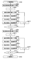
図14は、第1の実施の形態に係るX線検査全体の流れをフローチャート形式で示す図である。図14を参照して、第1の実施の形態に係るX線検査全体の流れについて説明する。
(Flow of processing)
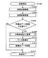
FIG. 14 is a diagram showing the flow of the entire X-ray examination according to the first embodiment in the form of a flowchart. The flow of the entire X-ray examination according to the first embodiment will be described with reference to FIG.
図14を参照して、まず、処理が開始されると(ステップS1400)、X線検査装置100は、検査対象領域を撮像可能な位置に移動し、透視画像の撮像を行なう(ステップS1402)。通常、X線検査においては、検査対象1の位置の特定のために光学カメラ(図示せず)が搭載されており、光学カメラの画像をもとに検査対象領域を決めることが可能である。その他の方法として、検査対象領域は、検査対象1のCADデータをもとにX線検査装置100が、自動的に決めてもよいし、作業者が目視で決定してもよい。
Referring to FIG. 14, first, when the process is started (step S1400), X-ray inspection apparatus 100 moves the region to be inspected to a position where it can be imaged, and performs imaging of a fluoroscopic image (step S1402). Usually, in X-ray inspection, an optical camera (not shown) is mounted to specify the position of the inspection object 1, and it is possible to determine the inspection object area based on the image of the optical camera. As another method, the X-ray inspection apparatus 100 may automatically determine the inspection target area based on the CAD data of the inspection target 1, or the operator may visually determine it.
X線検査装置100は、透視画像を検査して、取得した透視画像に基づいて、検査対象1の視野(透視画像で撮像されている範囲)の良否判定を行なう(ステップS1404)。良否判定手法は、様々な手法が提案されており、公知のためここでは詳細を記述しない。例えば、もっとも基本的な検査としては、透視画像を一定の値で2値化し、CADデータ等の設計情報と比較し、透視画像上の所定の位置に部品があるかないかを面積により判断する。
The X-ray examination apparatus 100 examines the fluoroscopic image, and based on the acquired fluoroscopic image, determines the quality of the visual field of the examination object 1 (the range imaged in the fluoroscopic image) (step S1404). Various quality evaluation methods have been proposed, and the details are not described here because they are known. For example, as the most basic inspection, a fluoroscopic image is binarized with a fixed value, compared with design information such as CAD data, and it is determined by area whether or not there is a part at a predetermined position on the fluoroscopic image.
続いて、X線検査装置100は、再構成データ画像による検査が必要か否かを判断する(ステップS1406)。判断の基準は、CADデータ等の設計情報をもとに予め設定しておくことができるし、透視画像の良否判定結果から判断することも可能である。例えば、実装基板の検査において、片面にのみ部品が実装されている場合、透視画像で良否判定することが可能なため再構成画像による良否判定を行なう必要がない場合もある。
Subsequently, the X-ray inspection apparatus 100 determines whether an inspection by the reconstructed data image is necessary (step S1406). The reference of judgment can be set in advance based on design information such as CAD data, or can be judged from the result of pass / fail judgment of the fluoroscopic image. For example, when the component is mounted on only one side in the inspection of the mounting substrate, it may be possible to determine the quality based on the fluoroscopic image, and in some cases it may not be necessary to perform the quality determination based on the reconstructed image.
再構成データによる検査が必要ない場合には(ステップS1406においてNO)、X線検査装置100は、検査を終了する(ステップS1414)。
If the examination based on the reconstruction data is not necessary (NO in step S1406), the X-ray examination apparatus 100 ends the examination (step S1414).
一方、再構成画像による検査が必要な場合は(ステップS1406においてYES)、X線検査装置100は、続いて、検査対象領域についてのCT撮像を行なう(ステップS1408)。X線検査装置100は、CT撮像においては、検査対象領域を複数の方向から撮像する。ステップS1408の詳細については、後述する。
On the other hand, when the examination by the reconstructed image is necessary (YES in step S1406), the X-ray examination apparatus 100 subsequently performs CT imaging on the examination target area (step S1408). In CT imaging, the X-ray inspection apparatus 100 images an inspection target area from a plurality of directions. Details of step S1408 will be described later.
次に、X線検査装置100は、複数方向の撮像画像から再構成データを生成する(ステップS1410)。再構成処理は、様々な方法が提案されており、たとえば、Feldkamp法を用いることができる。
Next, the X-ray inspection apparatus 100 generates reconstruction data from captured images in a plurality of directions (step S1410). Various methods have been proposed for the reconstruction process, and for example, the Feldkamp method can be used.
続けて、X線検査装置100は、再構成データによる良否判定を行なう(ステップS1410)。良否判定の方法は、3次元データを直接用いる方法や2次元データ(断層画像)、1次元データ(プロファイル)を用いる等の方法が考えられる。これらの良否判定手法は周知であるため検査項目に適した良否判定手法を用いればよく、ここでは詳細の説明は繰り返さない。以下に、良否判定の1例について説明する。まず、3次元再構成データに一定の値で2値化する。CADデータ等の設計情報から、再構成データ内で部品(たとえば、BGAの半田ボール)のある位置を特定する。2値化画像から部品のある位置に隣接した画素の体積を計算し、部品のあるなしを判断することができる。以上で、X線検査装置100は、検査を終了する(ステップS1414)。
Subsequently, the X-ray inspection apparatus 100 performs quality determination based on the reconstruction data (step S1410). The quality determination method may be a method using three-dimensional data directly or a method using two-dimensional data (tomographic image) or one-dimensional data (profile). Since these quality determination methods are well known, the quality determination method suitable for the inspection item may be used, and the detailed description will not be repeated here. One example of the quality determination will be described below. First, the three-dimensional reconstruction data is binarized with a fixed value. From design information such as CAD data, a position of a part (for example, a solder ball of BGA) is specified in the reconstruction data. From the binarized image, the volume of pixels adjacent to a certain position of the part can be calculated to determine the presence or absence of the part. Above, X-ray inspection apparatus 100 ends an inspection (Step S1414).
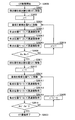
第1の実施の形態に係るCT撮像の詳細について、図15を参照して説明する。図15は、図14で説明したCT撮像の処理の流れをフローチャート形式で示す図である。
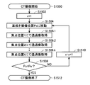
The details of the CT imaging according to the first embodiment will be described with reference to FIG. FIG. 15 is a diagram showing the flow of processing of CT imaging described in FIG. 14 in the form of a flowchart.
図15を参照して、まず、CT撮像処理が開始されると(ステップS1500)、演算部70は、ステップS1502において、撮像位置Pxについてのパラメータを初期化する(x=1に設定する)。
Referring to FIG. 15, first, when CT imaging processing is started (step S1500), operation unit 70 initializes parameters for imaging position Px (set to x = 1) in step S1502.
ステップS1504において、演算部70は、検査したい検査対象領域を適切な位置に移動させるために、検査対象1を位置Pxに移動させる。検査対象1の位置は、検査対象駆動機構20にエンコーダが搭載されていれば、エンコーダを用いて設定してもよい。あるいは、汎用的な検出器(レーザー変位計等)を用いて、これらの位置を設定してもよい。
In step S1504, the computing unit 70 moves the inspection target 1 to the position Px in order to move the inspection target area to be inspected to an appropriate position. If the encoder is mounted on the inspection target drive mechanism 20, the position of the inspection target 1 may be set using the encoder. Alternatively, these positions may be set using a general-purpose detector (laser displacement meter or the like).
続いて、演算部70は、X線焦点位置17を各焦点位置(F1~Fk)に設定して、X線を照射するとともに、透過像を取得する(ステップS1506.1~ステップS1506.k)。撮像時間(検出器の露光時間)は予め設定しておいてもよいし、ユーザが目視により所望の時間に設定することもできる。すでに説明したように、演算部70は、これらの処理において、各部分領域に対応する部分画像を取得する。また、演算部70は、部分画像を、再構成部76での再構成処理のために、たとえば、メモリ90に転送する。
Subsequently, the calculation unit 70 sets the X-ray focal position 17 to each focal position (F1 to Fk), irradiates X-rays, and acquires a transmission image (steps S1506.1 to S1506.k). . The imaging time (exposure time of the detector) may be set in advance, or the user may set it to a desired time by visual observation. As described above, the computing unit 70 acquires a partial image corresponding to each partial region in these processes. Further, operation unit 70 transfers the partial image to, for example, memory 90 for the reconstruction process in reconstruction unit 76.
続いて、演算部70は、Px=Peである否かを判断する(ステップS1508)。例えば、演算部70は、基板の移動回数が所定の回数に達したかどうかに基づいてこの判断を行なう。あるいは、演算部70は、位置センサによる基板位置の測定結果に基づいて、この判断を行なってもよい。
Subsequently, operation unit 70 determines whether or not Px = Pe (step S1508). For example, the computing unit 70 makes this determination based on whether or not the number of movements of the substrate has reached a predetermined number. Alternatively, the calculation unit 70 may make this determination based on the measurement result of the substrate position by the position sensor.
Px=Peでない場合(ステップS1508においてNO)、演算部70は、ステップS1510において、x=x+1に設定したあと、ステップS1504からの処理を繰り返す。一方、Px=Peの場合(ステップS1508においてYES)、演算部70は、CT撮像処理を終了する(ステップS1512)。
If Px = Pe is not satisfied (NO in step S1508), operation unit 70 repeats the process from step S1504 after setting x = x + 1 in step S1510. On the other hand, if Px = Pe (YES in step S1508), operation unit 70 ends the CT imaging process (step S1512).
(その他)
以上の説明では、検査対象領域が部分領域に分割されているとしたが、検査対象領域が部分領域程度の大きさであれば、検査対象領域を分割する必要はない。あるいは、X線検出器が検査対象に対し十分大きければ、検査対象領域を分割する必要はない。ただし、大きなサイズのX線検出器は高価であることを考えると、本実施の形態のように検査対象を部分領域に分割し、各部分領域の3次元データを再構成する手法が、実用的である。
(Others)
In the above description, the inspection target area is divided into partial areas. However, if the inspection target area is about the size of the partial area, it is not necessary to divide the inspection target area. Alternatively, if the X-ray detector is sufficiently large relative to the examination object, it is not necessary to divide the examination object area. However, considering that the large-sized X-ray detector is expensive, it is practical to divide the inspection object into partial areas as in this embodiment and reconstruct three-dimensional data of each partial area. It is.
上述した実施の形態によれば、X線源10のX線焦点位置17を第1の方向(上述の例では、X方向)に走査し、第1の方向について複数の部分領域に分割された検査対象領域の各々について、各X線焦点位置17から出力し、各部分領域を透過したX線に対応する部分画像を用いて、検査対象領域の3次元データを再構成する。
According to the embodiment described above, the X-ray focal position 17 of the X-ray source 10 is scanned in the first direction (the X direction in the above example), and divided into a plurality of partial areas in the first direction The three-dimensional data of the region to be inspected is reconstructed using partial images corresponding to the X-rays output from the X-ray focal positions 17 and transmitted through the partial regions for each of the regions to be inspected.
このような構成を採用することで、第1の方向に沿ってX線検出器23が存在しなければならない範囲をより少なくすることができるとともに、CT再構成に必要な複数方向からの検査対象1のX線透過画像をより高速に取得することができる。
By adopting such a configuration, the range in which the X-ray detector 23 has to be present along the first direction can be further reduced, and the examination object from multiple directions necessary for CT reconstruction The X-ray transmission image of 1 can be acquired faster.
[第2の実施の形態]
(構成)
第2の実施の形態に係るX線検査装置200の構成について図16を参照して説明する。図16は、第2の実施の形態に係るX線検査装置200の構成を説明するための図である。
Second Embodiment
(Constitution)
The configuration of the X-ray inspection apparatus 200 according to the second embodiment will be described with reference to FIG. FIG. 16 is a diagram for explaining the configuration of the X-ray inspection apparatus 200 according to the second embodiment.
X線検査装置200は、X線源10と、X線検出器23.1および23.2と、X線検出器駆動部22と、画像取得制御機構30と、入力部40と、出力部50と、X線源制御機構60と、演算部70と、メモリ90とを備える。X線源制御機構60、演算部70、および、メモリ90は、図1を参照して説明したような構成を有する。
The X-ray inspection apparatus 200 includes an X-ray source 10, X-ray detectors 23.1 and 23.2, an X-ray detector drive unit 22, an image acquisition control mechanism 30, an input unit 40, and an output unit 50. , An X-ray source control mechanism 60, an operation unit 70, and a memory 90. The X-ray source control mechanism 60, the computing unit 70, and the memory 90 have the configuration as described with reference to FIG.
第1の実施の形態と異なるのは、X線検出器駆動部22があること、画像取得制御機構30が、検出器駆動制御部32を含むこと、および、X線検出器が2つあることである。
The difference from the first embodiment is that there is an X-ray detector drive unit 22, that the image acquisition control mechanism 30 includes a detector drive control unit 32, and that there are two X-ray detectors. It is.
大きなサイズのX線検出器は高価で、画像の読み取り速度が遅い。実用性の向上のため、第2の実施の形態では、第1の実施の形態のX線検出器23の1/4程度のサイズのX線検出器23.1およびX線検出器23.2を利用する。
Large size X-ray detectors are expensive and have slow image reading speeds. In order to improve practicability, in the second embodiment, the X-ray detector 23.1 and the X-ray detector 23.2, which are about 1/4 the size of the X-ray detector 23 of the first embodiment. Use
X線検出器23.1およびX線検出器23.2は、X方向に並べられて配置されている。X線検出器23.1およびX線検出器23.2は、X線検出器駆動部22に取り付けられている。X線検出器駆動部22は、検出器駆動制御部32の指示に基づいて動作し、X線検出器23.1およびX線検出器23.2を一体的にY方向に移動する。
The X-ray detector 23.1 and the X-ray detector 23.2 are arranged side by side in the X direction. The X-ray detector 23.1 and the X-ray detector 23.2 are attached to the X-ray detector drive unit 22. The X-ray detector drive unit 22 operates based on an instruction of the detector drive control unit 32, and moves the X-ray detector 23.1 and the X-ray detector 23.2 integrally in the Y direction.
本実施の形態では、第1の実施の形態と比較して、検出器のY方向のサイズが小さい。本実施の形態では、X線検出器駆動部22が、X線検出器の組を一体的にY方向に移動することで、これをカバーする。
In the present embodiment, the size in the Y direction of the detector is smaller than in the first embodiment. In the present embodiment, the X-ray detector drive unit 22 covers the X-ray detector set 22 by integrally moving the set of X-ray detectors in the Y direction.
(撮像方式)
ここからは、X線検査装置200を用いたX線透視画像の撮像方式について説明する。
(Imaging method)
From here, an imaging method of an X-ray fluoroscopic image using the X-ray inspection apparatus 200 is described.
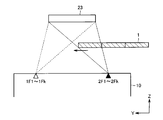
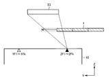
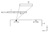
まず、図17から図19を用いて、X線検出器23.1,23.2、検査対象1、および、X線焦点位置17の位置関係について説明する。図17は、X線検出器23.1,23.2、検査対象1、および、X線焦点位置17をY方向から見た正面図である。図18は、X線検出器23.1,23.2、検査対象1、および、X線焦点位置17をZ方向から見た上面図である。図19は、X線検出器23.1,23.2、検査対象1、および、X線焦点位置17をX方向から見た側面図である。
First, the positional relationship between the X-ray detectors 23.1, 23.2, the inspection target 1, and the X-ray focal position 17 will be described with reference to FIGS. FIG. 17 is a front view of the X-ray detectors 23.1, 23.2, the inspection target 1, and the X-ray focal position 17 as viewed from the Y direction. FIG. 18 is a top view of the X-ray detectors 23.1, 23.2, the inspection object 1, and the X-ray focal position 17 as viewed from the Z direction. FIG. 19 is a side view of the X-ray detectors 23.1, 23.2, the inspection target 1, and the X-ray focal position 17 as viewed from the X direction.
図17~19におけるX線検出器23.1,23.2は、それぞれX線検出器23.1,23.2の受光部と置き換えて考えてよい。
The X-ray detectors 23.1 and 23.2 in FIGS. 17 to 19 may be considered to be replaced with the light receiving portions of the X-ray detectors 23.1 and 23.2, respectively.
図17を参照して、X線検出器23.1および23.2は、X方向に近接している。また、これらのX方向の幅の合計は、検査対象領域のX方向両端部について、必要な角度からの透過画像を取得できるサイズとする。なお、ここでは、検査対象1の全面が検査対象領域であるとしている。斜めCTのためには、X線検出器23.1および23.2のX方向幅の和は、検査対象1のX方向長さに比べ、長くなっている必要がある。
Referring to FIG. 17, X-ray detectors 23.1 and 23.2 are close in the X direction. In addition, the sum of the widths in the X direction is set such that transmission images from necessary angles can be obtained at both ends of the inspection target area in the X direction. Here, it is assumed that the entire surface of the inspection object 1 is the inspection object area. For oblique CT, the sum of the X-direction widths of the X-ray detectors 23.1 and 23.2 needs to be longer than the X-direction length of the inspection object 1.
第1の実施の形態と同様、X線源10は、X方向のライン上の互いに異なる複数の焦点位置(図においてF1~Fk)で、X線をZ方向に順次放射する。X線検出器23.1および23.2は、図18にしめす検出位置S1で、一照射毎に透過画像を取得する。
As in the first embodiment, the X-ray source 10 sequentially emits X-rays in the Z direction at a plurality of different focal positions (F1 to Fk in the figure) on the line in the X direction. The X-ray detectors 23.1 and 23.2 acquire transmission images for each irradiation at the detection position S1 shown in FIG.
図19の下側の図を参照して、X線検査装置200は、X線を焦点位置F1からFkのそれぞれで照射および撮像した後、検査対象1を位置P1からP2へY方向移動させて、F1~Fkでの照射および撮像を行なう。X線検査装置200は、同様に、X線照射と検査対象1の移動とを繰り返す。図19における位置Peで検査対象1の照射および撮像が終わると、検出位置S1でのCT撮像は終了となる。これらの処理は第1の実施の形態と同様である。
Referring to the lower side of FIG. 19, X-ray inspection apparatus 200 irradiates and captures X-rays at focal positions F1 to Fk respectively, and then moves inspection object 1 from position P1 to P2 in the Y direction. , Irradiation and imaging in F1 to Fk. Similarly, the X-ray inspection apparatus 200 repeats X-ray irradiation and movement of the inspection object 1. When the irradiation and imaging of the inspection target 1 are completed at the position Pe in FIG. 19, the CT imaging at the detection position S1 ends. These processes are similar to those of the first embodiment.
その後、X線検査装置200は、図19の上側の図に示すように、検出器位置をS2に、基板位置をP1’に移動させる。X線検査装置200は、検査対象のY方向最終行がPe’で撮像を終えるまで、F1~Fkでの照射およびY方向への検査対象移動を繰り返す。
After that, the X-ray inspection apparatus 200 moves the detector position to S2 and the substrate position to P1 ', as shown in the upper drawing of FIG. The X-ray inspection apparatus 200 repeats the irradiation with F1 to Fk and the movement of the inspection object in the Y direction until the last line in the Y direction of the inspection object ends imaging in Pe ′.
(処理の流れ)
第2の実施の形態に係るX線検査方法の大きな流れは、第1の実施の形態と同様であり、繰り返さない。ただし、CT撮像処理が第1の実施の形態と異なる。第2の実施の形態に係るCT撮像の詳細について、図20を参照して説明する。図20は、第2の実施の形態に係るCT撮像の処理の流れをフローチャート形式で示す図である。
(Flow of processing)
The large flow of the X-ray inspection method according to the second embodiment is the same as that of the first embodiment and will not be repeated. However, CT imaging processing is different from that of the first embodiment. The details of CT imaging according to the second embodiment will be described with reference to FIG. FIG. 20 is a diagram showing, in a flowchart form, a flow of processing of CT imaging according to the second embodiment.
図20を参照して、まず、CT撮像処理が開始されると(ステップS2000)、演算部70は、ステップS2001において、X線検出器23.1および23.2を検出器位置S1に移動する。
Referring to FIG. 20, first, when CT imaging processing is started (step S2000), operation unit 70 moves X-ray detectors 23.1 and 23.2 to detector position S1 in step S2001. .
ステップS2002において、検出器位置S1で撮像する場合の撮像位置Pxについてのパラメータを初期化する(x=1に設定する)。
In step S2002, parameters for the imaging position Px in the case of imaging at the detector position S1 are initialized (set to x = 1).
ステップS2004において、演算部70は、検査したい検査対象領域を適切な位置に移動させるために、検査対象1を位置Pxに移動させる。
In step S2004, the arithmetic unit 70 moves the inspection target 1 to the position Px in order to move the inspection target area to be inspected to an appropriate position.
続いて、演算部70は、X線焦点位置17を各焦点位置(F1~Fk)に設定して、X線を照射するとともに、検出器位置S1で透過像を取得する(ステップS2006.1~ステップS2006.k)。演算部70は、これらの処理において、各部分領域に対応する部分画像を取得する。また、演算部70は、部分画像を、再構成部76での再構成処理のために、たとえば、メモリ90に転送する。
Subsequently, the computing unit 70 sets the X-ray focal position 17 to each focal position (F1 to Fk), irradiates X-rays, and acquires a transmission image at the detector position S1 (step S2006.1 Step S2006.k). In these processes, the arithmetic unit 70 obtains partial images corresponding to the respective partial regions. Further, operation unit 70 transfers the partial image to, for example, memory 90 for the reconstruction process in reconstruction unit 76.
続いて、演算部70は、Px=Peであるか否かを判断する(ステップS2008)。例えば、演算部70は、基板の移動回数が所定の回数に達したかどうかに基づいてこの判断を行なう。あるいは、演算部70は、位置センサによる基板位置の測定結果に基づいて、この判断を行なってもよい。
Subsequently, operation unit 70 determines whether Px = Pe (step S2008). For example, the computing unit 70 makes this determination based on whether or not the number of movements of the substrate has reached a predetermined number. Alternatively, the calculation unit 70 may make this determination based on the measurement result of the substrate position by the position sensor.
Px=Peでない場合(ステップS2008においてNO)、演算部70は、ステップS2010において、x=x+1に設定したあと、ステップS2004からの処理を繰り返す。
If Px = Pe is not satisfied (NO in step S2008), operation unit 70 repeats the process from step S2004 after setting x = x + 1 in step S2010.
一方、Px=Peの場合(ステップS2008においてYES)、演算部70は、ステップS2011において、X線検出器23.1および23.2を検出器位置S2に移動する。
On the other hand, if Px = Pe (YES in step S2008), operation unit 70 moves X-ray detectors 23.1 and 23.2 to detector position S2 in step S2011.
ステップS2012において、検出器位置S2で撮像する場合の撮像位置Px’についてのパラメータを初期化する(x’=1に設定する)。
In step S2012, parameters for the imaging position Px 'in the case of imaging at the detector position S2 are initialized (set to x' = 1).
ステップS2014において、演算部70は、検査したい検査対象領域を適切な位置に移動させるために、検査対象1を位置Px’に移動させる。
In step S2014, the arithmetic unit 70 moves the inspection target 1 to the position Px 'in order to move the inspection target area to be inspected to an appropriate position.
続いて、演算部70は、X線焦点位置17を各焦点位置(F1~Fk)に設定して、X線を照射するとともに、検出器位置S2で透過像を取得する(ステップS2016.1~ステップS2016.k)。演算部70は、これらの処理において、各部分領域に対応する部分画像を取得する。また、演算部70は、部分画像を、再構成部76での再構成処理のために、たとえば、メモリ90に転送する。
Subsequently, the calculation unit 70 sets the X-ray focal position 17 to each focal position (F1 to Fk), irradiates X-rays, and acquires a transmission image at the detector position S2 (step S2016.1 to Step S2016. K). In these processes, the arithmetic unit 70 obtains partial images corresponding to the respective partial regions. Further, operation unit 70 transfers the partial image to, for example, memory 90 for the reconstruction process in reconstruction unit 76.
続いて、演算部70は、Px’=Pe’であるか否かを判断する(ステップS2018)。例えば、演算部70は、基板の移動回数が所定の回数に達したかどうかに基づいてこの判断を行なう。あるいは、演算部70は、位置センサによる基板位置の測定結果に基づいて、この判断を行なってもよい。
Subsequently, operation unit 70 determines whether Px '= Pe' (step S2018). For example, the computing unit 70 makes this determination based on whether or not the number of movements of the substrate has reached a predetermined number. Alternatively, the calculation unit 70 may make this determination based on the measurement result of the substrate position by the position sensor.
Px’=Pe’でない場合(ステップS2018においてNO)、演算部70は、ステップS2020において、x’=x’+1に設定したあと、ステップS2014からの処理を繰り返す。
If Px '= Pe' (NO in step S2018), operation unit 70 repeats the process from step S2014 after setting x '= x' + 1 in step S2020.
一方、Px=Peの場合(ステップS2018においてYES)、演算部70は、CT撮像処理を終了する(ステップS2022)。
On the other hand, if Px = Pe (YES in step S2018), operation unit 70 ends the CT imaging process (step S2022).
(その他)
以上では、検出器位置を1回移動する例を説明したが、Y方向の検出器サイズおよび必要とされる撮像枚数によっては、X線検査装置200は、検出器位置を2回以上移動して、撮像してもよい。
(Others)
Although the example in which the detector position is moved once has been described above, the X-ray inspection apparatus 200 moves the detector position two or more times depending on the size of the detector in the Y direction and the number of imaging required. , May be imaged.
[第3の実施の形態]
第3の実施の形態として、2ライン上でX線を走査する走査型X線源を備えるX線検出装置について説明する。なお、第3の実施の形態に係るX線検出装置の構成は、X線源10を除いて、第2の実施の形態と同様であるものとする。そのため、その構成の説明は繰り返さない。
Third Embodiment
As a third embodiment, an X-ray detection apparatus provided with a scanning X-ray source that scans X-rays on two lines will be described. The configuration of the X-ray detection apparatus according to the third embodiment is the same as that of the second embodiment except for the X-ray source 10. Therefore, the description of the configuration will not be repeated.
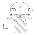
第3の実施の形態に係るX線源10の構成を図21および図22を参照して説明する。図21は、第3の実施の形態に係るX線源10の断面図である。図22は、第3の実施の形態に係るX線源10の上面図である。
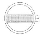
The configuration of the X-ray source 10 according to the third embodiment will be described with reference to FIGS. 21 and 22. FIG. 21 is a cross-sectional view of the X-ray source 10 according to the third embodiment. FIG. 22 is a top view of the X-ray source 10 according to the third embodiment.
このX線源10は、対向する2つの直線状のターゲット11.1および11.2を備える点が第1の実施の形態のものと異なる。他の主要な構成は、第1の実施の形態のものと同様であるので、その説明は繰り返さない。
This X-ray source 10 differs from that of the first embodiment in that it comprises two opposed linear targets 11.1 and 11.2. The other main components are the same as those of the first embodiment, and the description thereof will not be repeated.
図21を参照して、ターゲット11.1および11.2は、電子ビーム16の反射方向に進行するX線18が外部に向けて出力するように配置された反射型のターゲットである。すなわち、X線源10は、反射型X線源である。ターゲットとして反射型ターゲットを用いることで、X線源10は、透過型のX線源と比較して、高強度のX線を出力することができる。これは、撮像時間の短縮および高画質化に寄与する。
Referring to FIG. 21, targets 11.1 and 11.2 are reflective targets arranged such that X-rays 18 traveling in the reflection direction of electron beam 16 are output to the outside. That is, the X-ray source 10 is a reflective X-ray source. By using a reflective target as a target, the X-ray source 10 can output high-intensity X-rays as compared to a transmissive X-ray source. This contributes to shortening of imaging time and high image quality.
図22を参照して、X線源10の真空窓130は、ターゲット11.1および11.2を覆うように配置される。真空窓130は、ベリリウムなどX線を透過する材料でできている。なお、真空窓130の形状は図22に示したものに限られず、CT撮像に必要な方向のX線が進行する範囲に設置されていればよい。
Referring to FIG. 22, vacuum window 130 of X-ray source 10 is arranged to cover targets 11.1 and 11.2. The vacuum window 130 is made of a material that transmits X-rays, such as beryllium. The shape of the vacuum window 130 is not limited to that shown in FIG. 22 and may be installed in a range in which X-rays in the direction necessary for CT imaging travel.
図23から図25に、X線検出器23.1,23.2、検査対象1、および、X線焦点位置17の位置関係を示す。図23は、X線検出器23.1,23.2、検査対象1、および、X線焦点位置17をY方向から見た正面図である。図24は、X線検出器23.1,23.2、検査対象1、および、X線焦点位置17をZ方向から見た上面図である。図25は、X線検出器23.1,23.2、検査対象1、および、X線焦点位置17をX方向から見た側面図である。
The positional relationship between the X-ray detectors 23.1, 23.2, the inspection object 1, and the X-ray focal position 17 is shown in FIGS. FIG. 23 is a front view of the X-ray detectors 23.1, 23.2, the inspection target 1, and the X-ray focal position 17 as viewed from the Y direction. FIG. 24 is a top view of the X-ray detectors 23.1, 23.2, the inspection target 1, and the X-ray focal position 17 as viewed from the Z direction. FIG. 25 is a side view of the X-ray detectors 23.1, 23.2, the inspection target 1, and the X-ray focal position 17 as viewed from the X direction.
図23を参照して、第2の実施の形態と同様、X線検出器23.1および23.2は、X方向に近接している。また、これらのX方向の幅の合計は、検査対象領域のX方向両端部について、必要な角度からの透過画像を取得できるサイズとする。なお、ここでは、検査対象1の全面が検査対象領域であるとしている。斜めCTのためには、X線検出器23.1および23.2のX方向幅の和は、検査対象1のX方向長さに比べ、長くなっている必要がある。
Referring to FIG. 23, as in the second embodiment, X-ray detectors 23.1 and 23.2 are close in the X direction. In addition, the sum of the widths in the X direction is set such that transmission images from necessary angles can be obtained at both ends of the inspection target area in the X direction. Here, it is assumed that the entire surface of the inspection object 1 is the inspection object area. For oblique CT, the sum of the X-direction widths of the X-ray detectors 23.1 and 23.2 needs to be longer than the X-direction length of the inspection object 1.
X線源10は、X方向のライン上の互いに異なる複数の焦点位置で、X線をZ方向に順次放射する。X線検出器23.1および23.2は、図24にしめす検出位置S1で、一照射毎に透過画像を取得する。このとき、X線源10は、X線焦点位置1F1~1Fkで、X線を放射する。
The X-ray source 10 sequentially emits X-rays in the Z direction at a plurality of different focal positions on the line in the X direction. The X-ray detectors 23.1 and 23.2 acquire transmission images for each irradiation at the detection position S1 shown in FIG. At this time, the X-ray source 10 emits X-rays at the X-ray focal positions 1F1 to 1Fk.
検出位置S1での撮像が完了すると、X線検査装置は、X線検出器23.1および23.2を検出位置S2に移動する。X線検出器23.1および23.2は、焦点位置2F2~2FkからのX線の透過画像を取得する。
When imaging at the detection position S1 is completed, the X-ray examination apparatus moves the X-ray detectors 23.1 and 23.2 to the detection position S2. The X-ray detectors 23.1 and 23.2 acquire transmission images of X-rays from the focal positions 2F2 to 2Fk.
つまり、図25の下側の図を参照して、X線検査装置は、X線を焦点位置1F1から1Fkのそれぞれで照射および撮像した後、検査対象1を位置P1からP2へY方向移動させ、1F1~1Fkでの照射および撮像を行なう。X線検査装置200は、同様に、X線照射と検査対象1の移動とを繰り返す。図25における位置Peで検査対象1の照射および撮像が終わると、検出位置S1でのCT撮像は終了となる。
That is, referring to the lower side of FIG. 25, the X-ray inspection apparatus irradiates and captures X-rays at focal positions 1F1 to 1Fk respectively, and then moves inspection object 1 from position P1 to P2 in the Y direction. , Irradiation and imaging at 1F1 to 1Fk. Similarly, the X-ray inspection apparatus 200 repeats X-ray irradiation and movement of the inspection object 1. When the irradiation and imaging of the inspection target 1 are completed at the position Pe in FIG. 25, the CT imaging at the detection position S1 ends.
その後、X線検査装置は、図25の上側の図に示すように、検出器位置をS2に、基板位置をP1’に移動させる。X線検査装置200は、検査対象のY方向最終行がPe’で撮像を終えるまで、2F1~2Fkでの照射およびY方向への検査対象移動を繰り返す。
Thereafter, the X-ray inspection apparatus moves the detector position to S2 and the substrate position to P1 ', as shown in the upper drawing of FIG. The X-ray examination apparatus 200 repeats irradiation with 2F1 to 2Fk and movement of the examination object in the Y direction until imaging is finished at the last line in the Y direction of the examination object at Pe ′.
以上のように、第3の実施の形態では、基本的な照射および撮像の方法は第2の実施の形態と同様であるが、検出器位置S1のときにはX線焦点1F1~1Fkを、検出器位置S2のときにはX線焦点2F1~2Fkを使用する。
As described above, in the third embodiment, the basic irradiation and imaging methods are the same as those in the second embodiment, but at the detector position S1, the X-ray focal points 1F1 to 1Fk are At the position S2, the X-ray focal points 2F1 to 2Fk are used.
第3の実施の形態に係るX線検査方法の大きな流れは、第1の実施の形態あるいは第2の実施の形態と同様であり、繰り返さない。ただし、CT撮像処理が第1の実施の形態および第2の実施の形態と異なる。第3の実施の形態に係るCT撮像の詳細について、図26を参照して説明する。図26は、第3の実施の形態に係るCT撮像の処理の流れをフローチャート形式で示す図である。
The large flow of the X-ray inspection method according to the third embodiment is the same as that of the first embodiment or the second embodiment and will not be repeated. However, the CT imaging process is different from the first embodiment and the second embodiment. The details of CT imaging according to the third embodiment will be described with reference to FIG. FIG. 26 is a diagram showing, in a flowchart form, a flow of processing of CT imaging according to the third embodiment.
図26を参照して、まず、CT撮像処理が開始されると(ステップS2600)、演算部70は、ステップS2601において、X線検出器23.1および23.2を検出器位置S1に移動する。
Referring to FIG. 26, first, when CT imaging processing is started (step S2600), operation unit 70 moves X-ray detectors 23.1 and 23.2 to detector position S1 in step S2601. .
ステップS2602において、検出器位置S1で撮像する場合の撮像位置Pxについてのパラメータを初期化する(x=1に設定する)。
In step S2602, parameters for the imaging position Px in the case of imaging at the detector position S1 are initialized (set to x = 1).
ステップS2604において、演算部70は、検査したい検査対象領域を適切な位置に移動させるために、検査対象1を位置Pxに移動させる。
In step S2604, the operation unit 70 moves the inspection target 1 to the position Px in order to move the inspection target area to be inspected to an appropriate position.
続いて、演算部70は、X線焦点位置17を焦点位置1F1~1Fkに設定して、X線を照射するとともに、検出器位置S1で透過像を取得する(ステップS2606.1~ステップS2606.k)。演算部70は、これらの処理において、各部分領域に対応する部分画像を取得する。また、演算部70は、部分画像を、再構成部76での再構成処理のために、たとえば、メモリ90に転送する。
Subsequently, the calculation unit 70 sets the X-ray focal position 17 to the focal positions 1F1 to 1Fk, irradiates X-rays, and acquires transmission images at the detector position S1 (steps S2606.1 to S2606. k). In these processes, the arithmetic unit 70 obtains partial images corresponding to the respective partial regions. Further, operation unit 70 transfers the partial image to, for example, memory 90 for the reconstruction process in reconstruction unit 76.
続いて、演算部70は、Px=Peであるか否かを判断する(ステップS2608)。例えば、演算部70は、基板の移動回数が所定の回数に達したかどうかに基づいてこの判断を行なう。あるいは、演算部70は、位置センサによる基板位置の測定結果に基づいて、この判断を行なってもよい。
Subsequently, operation unit 70 determines whether Px = Pe (step S2608). For example, the computing unit 70 makes this determination based on whether or not the number of movements of the substrate has reached a predetermined number. Alternatively, the calculation unit 70 may make this determination based on the measurement result of the substrate position by the position sensor.
Px=Peでない場合(ステップS2608においてNO)、演算部70は、ステップS2610において、x=x+1に設定したあと、ステップS2604からの処理を繰り返す。
If Px = Pe is not satisfied (NO in step S2608), operation unit 70 repeats the process from step S2604 after setting x = x + 1 in step S2610.
一方、Px=Peの場合(ステップS2608においてYES)、演算部70は、ステップS2611において、X線検出器23.1および23.2を検出器位置S2に移動する。
On the other hand, if Px = Pe (YES in step S2608), operation unit 70 moves X-ray detectors 23.1 and 23.2 to detector position S2 in step S2611.
ステップS2612において、検出器位置S2で撮像する場合の撮像位置Px’についてのパラメータを初期化する(x’=1に設定する)。
In step S2612, the parameters for the imaging position Px 'in the case of imaging at the detector position S2 are initialized (set to x' = 1).
ステップS2614において、演算部70は、検査したい検査対象領域を適切な位置に移動させるために、検査対象1を位置Px’に移動させる。
In step S2614, the computing unit 70 moves the inspection target 1 to the position Px 'in order to move the inspection target area to be inspected to an appropriate position.
続いて、演算部70は、X線焦点位置17を焦点位置2F1~2Fkに設定して、X線を照射するとともに、検出器位置S2で透過像を取得する(ステップS2616.1~ステップS2616.k)。演算部70は、これらの処理において、各部分領域に対応する部分画像を取得する。また、演算部70は、部分画像を、再構成部76での再構成処理のために、たとえば、メモリ90に転送する。
Subsequently, the computing unit 70 sets the X-ray focal position 17 to the focal positions 2F1 to 2Fk, irradiates X-rays, and acquires a transmission image at the detector position S2 (steps S2616.1 to S2616. k). In these processes, the arithmetic unit 70 obtains partial images corresponding to the respective partial regions. Further, operation unit 70 transfers the partial image to, for example, memory 90 for the reconstruction process in reconstruction unit 76.
続いて、演算部70は、Px’=Pe’であるか否かを判断する(ステップS2618)。例えば、演算部70は、基板の移動回数が所定の回数に達したかどうかに基づいてこの判断を行なう。あるいは、演算部70は、位置センサによる基板位置の測定結果に基づいて、この判断を行なってもよい。
Subsequently, operation unit 70 determines whether Px '= Pe' (step S2618). For example, the computing unit 70 makes this determination based on whether or not the number of movements of the substrate has reached a predetermined number. Alternatively, the calculation unit 70 may make this determination based on the measurement result of the substrate position by the position sensor.
Px’=Pe’でない場合(ステップS2618においてNO)、演算部70は、ステップS2620において、x’=x’+1に設定したあと、ステップS2614からの処理を繰り返す。
If Px '= Pe' (NO in step S2618), operation unit 70 repeats the process from step S2614 after setting x '= x' + 1 in step S2620.
一方、Px=Peの場合(ステップS2618においてYES)、演算部70は、CT撮像処理を終了する(ステップS2622)。
On the other hand, if Px = Pe (YES in step S2618), operation unit 70 ends the CT imaging process (step S2622).
[第4の実施の形態]
第3の実施の形態において、X線検出器23.1および23.2の配置を工夫することで、X線検出器の駆動を省略することができる。第4の実施の形態として、このようにX線検出器が配置されているX線検査装置について説明する。
Fourth Embodiment
In the third embodiment, the drive of the X-ray detector can be omitted by devising the arrangement of the X-ray detectors 23.1 and 23.2. As a fourth embodiment, an X-ray inspection apparatus in which the X-ray detector is disposed as described above will be described.
第4の実施の形態に係るX線検出装置の構成は、第3の実施の形態とほぼ同様であるものとする。そのため、その構成の説明は繰り返さない。ただし、X線検出器23.1および23.2の配置が異なる点、および、X線検出器駆動部22および検出器駆動制御部32を有さない点が、第3の実施の形態と異なる。
The configuration of the X-ray detection apparatus according to the fourth embodiment is substantially similar to that of the third embodiment. Therefore, the description of the configuration will not be repeated. However, it differs from the third embodiment in that the arrangement of the X-ray detectors 23.1 and 23.2 is different, and that the X-ray detector drive unit 22 and the detector drive control unit 32 are not provided. .
図27および図28を参照して、第4の実施の形態における、X線検出器23.1および23.2とX線焦点位置との位置関係について説明する。図27は、X線検出器23.1および23.2のXY平面内における位置を説明するための図である。図28は、X線検出器23.1および23.2のYZ平面内における位置を説明するための図である。
With reference to FIGS. 27 and 28, the positional relationship between the X-ray detectors 23.1 and 23.2 and the X-ray focal position in the fourth embodiment will be described. FIG. 27 is a diagram for explaining the positions of the X-ray detectors 23.1 and 23.2 in the XY plane. FIG. 28 is a diagram for describing the positions of X-ray detectors 23.1 and 23.2 in the YZ plane.
図27を参照して、X線検出器23.1および23.2は、Y方向について、X線走査の2つのラインに挟まれるように配置されている。なお、X線検出器23.1および23.2を合わせたX方向幅と、検査対象のX方向幅との関係は、第2の実施の形態あるいは第3の実施の形態と同様である。
Referring to FIG. 27, X-ray detectors 23.1 and 23.2 are arranged to be sandwiched between two lines of the X-ray scan in the Y direction. The relationship between the X-direction width obtained by combining the X-ray detectors 23.1 and 23.2 and the X-direction width of the inspection object is the same as that in the second embodiment or the third embodiment.
図28を参照して、X線検出器23.1および23.2(以下、これらをあわせてX線検出器23ともよぶ)と、検査対象1と、X線源10とのYZ平面内における位置関係は、第3の実施の形態と同様である。
28, X-ray detectors 23.1 and 23.2 (hereinafter collectively referred to as X-ray detector 23), inspection object 1 and X-ray source 10 in the YZ plane. The positional relationship is similar to that of the third embodiment.
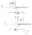
[規則91に基づく訂正 16.04.2010]
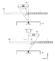
本実施の形態に係るX線検査方式は、基本的には、第3の実施の形態のものと同様である。しかしながら、本検査方式では、焦点位置1F1~1Fkと、焦点位置2F1~2FkでX線を照射する順序が、第3の実施の形態と異なる。本実施の形態に係るX線検査方式について、図29~図31を参照して説明する。図29~図31は、各々、第4の実施の形態に係るX線検査方式について説明するための図である。
[Correction based on rule 91 16.04.2010]
The X-ray inspection method according to the present embodiment is basically the same as that of the third embodiment. However, in the present inspection method, the order of irradiating X-rays at the focal positions 1F1 to 1Fk and the focal positions 2F1 to 2Fk is different from that of the third embodiment. The X-ray inspection method according to the present embodiment will be described with reference to FIGS. 29 to 31. FIGS. 29 to 31 are views for explaining the X-ray inspection method according to the fourth embodiment.
[規則91に基づく訂正 16.04.2010]
図29では、検査対象1は、焦点位置2F1~2Fk(以下、F2シリーズとよぶ)での撮像のみが有効な区間にある。このとき、X線源は、焦点位置1F1~1Fk(以下、F1シリーズとよぶ)では、X線を出力しない。
[Correction based on rule 91 16.04.2010]
In FIG. 29, the inspection object 1 is in a section in which only imaging at focal positions 2F1 to 2Fk (hereinafter referred to as F2 series) is effective. At this time, the X-ray source does not output X-rays at focal positions 1F1 to 1Fk (hereinafter referred to as F1 series).
図30では、図29に示す状態より検査対象1がY方向へ移動し、F1シリーズとF2シリーズとの両方による撮像が有効である。このとき、X線検出器23は、F1シリーズおよびF2シリーズの焦点位置で既定の枚数を撮像したのち、検査対象1を移動させる。
In FIG. 30, the inspection target 1 moves in the Y direction from the state shown in FIG. 29, and imaging by both the F1 series and the F2 series is effective. At this time, the X-ray detector 23 moves the inspection object 1 after imaging a predetermined number of sheets at the focal positions of the F1 series and the F2 series.
図31では、図30に示す状態より検査対象がY方向へ移動し、F1シリーズでの撮像のみが有効である。このとき、X線の照射に、F1シリーズの焦点位置は使用されない。
In FIG. 31, the inspection target moves in the Y direction from the state shown in FIG. 30, and only imaging in the F1 series is effective. At this time, the focal position of the F1 series is not used for X-ray irradiation.
以上の説明から分かるように、このジオメトリで撮像すれば、検出器駆動が不要であり、かつ、検査対象1の移動が一方向のみでよい(戻り動作が必要ない)。
As can be understood from the above description, if imaging is performed with this geometry, detector driving is not necessary, and the movement of the inspection object 1 may be in only one direction (the return operation is not necessary).
[その他]
上記の各実施の形態を適宜組み合わせたものも、本発明の範囲に含まれることはもちろんである。例えば、第3の実施の形態および第4の実施の形態においても、第1の実施の形態のように、複数のX線検出器のかわりに、大型の1枚のX線検出器を用いてもよい。
[Others]
Of course, any combination of the above-described embodiments is included in the scope of the present invention. For example, also in the third embodiment and the fourth embodiment, as in the first embodiment, one large X-ray detector is used instead of a plurality of X-ray detectors. It is also good.
今回開示された実施の形態はすべての点で例示であって制限的なものではないと考えられるべきである。本発明の範囲は上記した説明ではなくて請求の範囲によって示され、請求の範囲と均等の意味および範囲内でのすべての変更が含まれることが意図される。
It should be understood that the embodiments disclosed herein are illustrative and non-restrictive in every respect. The scope of the present invention is shown not by the above description but by the scope of claims, and is intended to include all modifications within the scope and meaning equivalent to the scope of claims.