装着式動作補助装置Wearable motion assist device
本発明は装着式動作補助装置に係る。例えば、指関節の動きを補助または代行するように構成された装着式動作補助装置に関する。
The present invention relates to a wearable motion assist device. For example, the present invention relates to a wearable motion assist device configured to assist or substitute for movement of a finger joint.
例えば、病気または怪我などにより脳からの神経伝達信号が伝わりにくくなったり、あるいは筋力の低下あるいは関節に設けられた腱や靭帯の損傷などにより手の指関節が本人の思い通りに動かなくなることがある。このような指関節の動作を補助する装着式動作補助装置としては、各指に装着される可動部と、各可動部を駆動するアクチュエータとを有する装置がある(例えば、特許文献1参照)。
For example, nerve transmission signals from the brain may be difficult to transmit due to illness or injury, or the finger joints of the hand may not move as intended due to weakness or damage to tendons or ligaments provided in the joints . As such a wearable movement assisting device that assists the movement of the finger joint, there is a device having a movable part that is worn on each finger and an actuator that drives each movable part (see, for example, Patent Document 1).
しかしながら、上記従来の装着式動作補助装置では、人間の手と同様に各指の関節に対応する回動機構が設けられ、各アクチュエータの駆動力を機械的に各可動部に伝達する構成であるので、部品点数が多く、複雑な構成であるので、かなりの重量を有し、装着者の負担が大きいという問題がある。
However, the conventional wearable motion assisting device is provided with a rotation mechanism corresponding to the joint of each finger like a human hand, and mechanically transmits the driving force of each actuator to each movable part. Therefore, since there are many parts and it is a complicated structure, there exists a problem that it has a considerable weight and the burden of a wearer is large.
また、上記従来の装着式動作補助装置では、アクチュエータを小型化して装置の重量を軽量化することが考えられるが、多数の部品からなる可動部の重量に対するトルクが不足するという問題がある。
特開2002-345861号公報
Further, in the conventional wearable motion assist device, it is conceivable to reduce the weight of the device by reducing the size of the actuator, but there is a problem that the torque with respect to the weight of the movable part made up of a large number of parts is insufficient.
JP 2002-345861 A
本発明は上記事情に鑑み、駆動部の駆動力を動作補助手袋に効率良く伝達する装着式動作補助装置を提供することを課題としている。
In view of the above circumstances, an object of the present invention is to provide a wearable movement assist device that efficiently transmits the driving force of the drive unit to the movement assist gloves.
本発明の一側面によれば、装着者の指が挿入される指挿入部を有する動作補助手袋と、前記動作補助手袋の甲側に配置され、前記指挿入部を駆動する駆動部と、前記駆動部の駆動力を前記指挿入部に伝達するように前記指挿入部の延在方向に沿うように配された線状部材と、前記装着者の指を動作させるための生体信号を検出する生体信号検出部と、該生体信号検出部により生成された生体信号に基づいて前記駆動部へ駆動制御信号を出力する制御部と、を備え、前記駆動部は、前記制御部からの駆動制御信号に基づいて前記線状部材を前記指挿入部の伸展方向または屈曲方向に動作させることを特徴とする装着式動作補助装置を提供する。
According to one aspect of the present invention, an operation assisting glove having a finger insertion part into which a wearer's finger is inserted, a drive unit disposed on the back side of the operation assisting glove, and driving the finger insertion part, A linear member arranged along the extending direction of the finger insertion part so as to transmit the driving force of the driving part to the finger insertion part, and a biological signal for operating the wearer's finger are detected. A biological signal detection unit; and a control unit that outputs a drive control signal to the drive unit based on the biological signal generated by the biological signal detection unit, wherein the drive unit receives a drive control signal from the control unit. The wearable motion assisting device is characterized in that the linear member is moved in the extending direction or the bending direction of the finger insertion portion.
本発明の一側面によれば、制御部からの駆動制御信号に基づいて線状部材を指の関節の動作方向に伸展または屈曲させることにより、装着者の指の関節を動作させるように駆動部の駆動力を伝達することができるので、軽量化を図ることができると共に、駆動部の駆動力を動作補助手袋に効率良く伝達して装着者の負担を軽減することが可能になる。
According to an aspect of the present invention, the drive unit is configured to operate the wearer's finger joint by extending or bending the linear member in the operation direction of the finger joint based on a drive control signal from the control unit. Therefore, the weight can be reduced, and the driving force of the driving unit can be efficiently transmitted to the operation assisting gloves to reduce the burden on the wearer.
本発明の他の目的、特徴及び利点は添付の図面を参照し以下の詳細な説明を読むことにより、一層明瞭となるであろう。
本発明による装着式動作補助装置の実施例1を示す平面図である。
実施例1の装着式動作補助装置10を側方からみた外観図である。
実施例1の装着式動作補助装置10を用いて物体を把持した動作状態を示す外観図である。
線状部材50及び駆動部40の構成を模式的に示す図である。
図3A中A-A線に沿う縦断面図である。
線状部材50が屈曲動作した状態を示す図である。
制御ユニット70を含む制御系及び充電システムの概略構成を模式的に示す図である。
実施例1の制御部100Aのシステム系統図である。
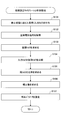
生体電位信号から各制御信号を生成する過程を示す図である。
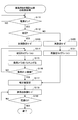
制御部100Aが実行する制御処理の手順の一例の第一部部を説明するためのフローチャートである。
制御部100Aが実行する制御処理の手順の一例の第二部を説明するためのフローチャートである。
実施例2の制御部100Bの信号処理を模式的に示すシステム系統図である。
各指の基本動作として、指を伸ばす(タスクA)、物を把持(タスクB)、指を曲げる(タスクC)、および握手(タスクD)を模式的に例示する図である。
データベース300に格納されている各タスク及び各フェーズを模式的に示す図である。
物理量を基準パラメータと比較することにより装着者が行おうとしているタスク、およびその中のフェーズを推定するプロセスを模式的に示す図である。
実施例2の制御部100Bが実行する制御処理の一例の第一部を示すフローチャートである。
実施例2の制御部100Bが実行する制御処理の一例の第二部を示すフローチャートである。
実施例3の制御部100Cの制御系の信号処理を模式的に示すシステム系統図である。
実施例3の制御部100Cが実行する制御処理の一例の第一部を示すフローチャートである。
実施例3の制御部100Cが実行する制御処理の一例の第二部を示すフローチャートである。
実施例4の制御部100Dの制御系の信号処理を模式的に示すシステム系統図である。
実施例4の制御部100Dが実行する制御処理の一例の第一部を示すフローチャートである。
実施例4の制御部100Dが実行する制御処理の一例の第二部を示すフローチャートである。
実施例5の制御部100Eの制御系の信号処理を模式的に示すシステム系統図である。
実施例5の制御部100Eが実行する制御処理の一例の第一部の手順を説明するためのフローチャートである。
実施例5の制御部100Eが実行する制御処理の一例の第二部の手順を説明するためのフローチャートである。
実施例6の制御部100Fの制御系の信号処理を模式的に示すシステム系統図である。
実施例6の制御部100Fが実行する制御処理の手順を説明するためのフローチャートである。
初期設定を行う初回キャリブレーションの制御手順を示すフローチャートである。
ワンモーション(1回の動作)による再設定キャリブレーションの制御手順を示すフローチャートである。
再設定モード2のキャリブレーション制御処理の制御手順を示すフローチャートである。
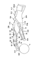
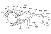
装着式動作補助装置10の変形例1を示す斜視図である。
変形例1の装着式動作補助装置10Aを側方からみた外観図である。
変形例1の装着式動作補助装置10Aを用いて物体を把持した動作状態を示す外観図である。
アクチュエータ510の内部構造を示す横断面図である。
図25A中D-D線に沿う縦断面図である。
変形例2の装着式動作補助装置10Bを示す斜視図である。
変形例2の装着式動作補助装置10Bを側方からみた外観図である。
変形例2の装着式動作補助装置10Bを用いて物体を把持した動作状態を示す外観図である。
変形例3の装着式動作補助装置10Cを示す平面図である。
変形例3の装着式動作補助装置10Cを側方からみた外観図である。
変形例3の装着式動作補助装置10Cを用いて物体を把持した動作状態を示す外観図である。
変形例4の装着式動作補助装置10Dを示す斜視図である。
変形例4の装着式動作補助装置10Dの指挿入部の一部を断面にして示す図である。
変形例4の装着式動作補助装置10Dの指挿入部が曲げられた動作状態を示す図である。
Other objects, features and advantages of the present invention will become more apparent upon reading the following detailed description with reference to the accompanying drawings.
It is a top view which shows Example 1 of the mounting | wearing type movement assistance apparatus by this invention. It is the external view which looked at the mounting | wearing type movement assistance apparatus 10 of Example 1 from the side. It is an external view which shows the operation state which hold | gripped the object using the mounting | wearing type movement assistance apparatus 10 of Example 1. FIG. FIG. 3 is a diagram schematically illustrating configurations of a linear member 50 and a drive unit 40. FIG. 3B is a longitudinal sectional view taken along line AA in FIG. 3A. It is a figure which shows the state which the linear member 50 bent. 2 is a diagram schematically showing a schematic configuration of a control system and a charging system including a control unit 70. FIG. FIG. 2 is a system diagram of a control unit 100A according to the first embodiment. It is a figure which shows the process of producing | generating each control signal from a biopotential signal. It is a flowchart for demonstrating the 1st part of an example of the procedure of the control processing which 100A of control parts perform. It is a flowchart for demonstrating the 2nd part of an example of the procedure of the control processing which 100A of control parts perform. FIG. 10 is a system diagram schematically illustrating signal processing of a control unit 100B according to the second embodiment. It is a figure which illustrates typically extending a finger (task A), grasping an object (task B), bending a finger (task C), and shaking hands (task D) as basic operation of each finger. FIG. 3 is a diagram schematically showing each task and each phase stored in a database 300. It is a figure which shows typically the process which the wearer is going to perform by comparing a physical quantity with a reference | standard parameter, and the process which estimates the phase in it. 10 is a flowchart illustrating a first part of an example of a control process executed by a control unit 100B according to the second embodiment. It is a flowchart which shows the 2nd part of an example of the control processing which the control part 100B of Example 2 performs. FIG. 10 is a system diagram schematically illustrating signal processing of a control system of a control unit 100C according to the third embodiment. 12 is a flowchart illustrating a first part of an example of a control process executed by a control unit 100C according to the third embodiment. It is a flowchart which shows the 2nd part of an example of the control processing which 100C of Example 3 performs. FIG. 10 is a system diagram schematically illustrating signal processing of a control system of a control unit 100D according to a fourth embodiment. 14 is a flowchart illustrating a first part of an example of a control process executed by a control unit 100D according to the fourth embodiment. It is a flowchart which shows the 2nd part of an example of the control processing which control part 100D of Example 4 performs. FIG. 10 is a system diagram schematically illustrating signal processing of a control system of a control unit 100E according to a fifth embodiment. 14 is a flowchart for explaining a first part of an example of a control process executed by a control unit 100E according to the fifth embodiment. It is a flowchart for demonstrating the procedure of the 2nd part of an example of the control processing which the control part 100E of Example 5 performs. FIG. 10 is a system diagram schematically illustrating signal processing of a control system of a control unit 100F according to a sixth embodiment. 16 is a flowchart for explaining a procedure of control processing executed by a control unit 100F according to the sixth embodiment. It is a flowchart which shows the control procedure of the first calibration which performs initial setting. It is a flowchart which shows the control procedure of the reset calibration by one motion (one operation | movement). 6 is a flowchart showing a control procedure of calibration control processing in reset mode 2. It is a perspective view which shows the modification 1 of the mounting | wearing type movement assistance apparatus. It is the external view which looked at the mounting | wearing type movement assistance apparatus 10A of the modification 1 from the side. It is an external view which shows the operation state which hold | gripped the object using 10 A of mounting | wearing type movement assistance apparatuses of the modification 1. 3 is a cross-sectional view showing an internal structure of an actuator 510. FIG. FIG. 25B is a longitudinal sectional view taken along line DD in FIG. 25A. It is a perspective view which shows the mounting | wearing type movement assistance apparatus 10B of the modification 2. FIG. It is the external view which looked at the mounting | wearing type movement assistance apparatus 10B of the modification 2 from the side. It is an external view which shows the operation state which hold | gripped the object using the mounting | wearing type movement assistance apparatus 10B of the modification 2. It is a top view which shows 10 C of mounting | wearing type movement assistance apparatuses of the modification 3. FIG. It is the external view which looked at the mounting | wearing type movement assistance apparatus 10C of the modification 3 from the side. It is an external view which shows the operation state which hold | gripped the object using the mounting | wearing type movement assistance apparatus 10C of the modification 3. It is a perspective view which shows mounting | wearing type movement assistance apparatus 10D of the modification 4. FIG. It is a figure which shows a part of finger insertion part of mounting | wearing type movement assistance apparatus 10D of the modification 4 in cross section. It is a figure which shows the operation | movement state by which the finger insertion part of mounting | wearing type movement assistance apparatus 10D of the modification 4 was bent.
10、10A~10D 装着式動作補助装置
20、20A~20D 動作補助手袋
21、21A~21D 指挿入部
22 開口
24 手首部
30 被駆動部
32、34、36 締結リング
40、510、710 駆動部
40a~40j 駆動機構
42 回動部材
44 電動モータ
50、50a~50j、500、700、800 線状部材
51 筒状体
52、53 ワイヤ
54 キャップ
55 中空部
57 上部空間
58 下部空間
59 中部空間
60 生体信号検出部
61~65 生体電位センサ
70、70A、70C、70D 制御ユニット
80、82 ベルト
84 面ファスナ
90 付勢部材
94 トルクセンサ
96 角度センサ
100、100A~100F 制御部
102 メモリ
104 表示器
124、610 充電式バッテリ
130 応力センサ
140 充電器
200 生体電位処理手段(生体信号処理手段)
202 増幅器
204 高帯域バンドパスフィルタ
206 中帯域バンドパスフィルタ
212 随意的制御手段
220 駆動電流生成手段
300 データベース
310 自律的制御手段
320 制御信号合成手段
400 キャリブレーションデータベース
410 フェーズ特定手段
420 差分導出手段
430 パラメータ補正手段
440 キャリブレーション制御手段
450 負荷発生手段
502 中空系路
510a~510j アクチュエータ
520 流動体
530 ハウジング
540 ペルチェ素子
612 太陽電池
600 物体検出センサ
710a~710j リニアモータ
810 印加電圧切替回路
801,802 電極層
803 駆動層
10, 10A to 10D Wearable motion assisting device 20, 20A to 20D Motion assisting gloves 21, 21A to 21D Finger insertion part 22 Opening 24 Wrist part 30 Driven parts 32, 34, 36 Fastening ring 40, 510, 710 Drive part 40a ˜40j Drive mechanism 42 Rotating member 44 Electric motor 50, 50a˜50j, 500, 700, 800 Linear member 51 Cylindrical body 52, 53 Wire 54 Cap 55 Hollow portion 57 Upper space 58 Lower space 59 Middle space 60 Biosignal Detection unit 61 to 65 Bioelectric potential sensor 70, 70A, 70C, 70D Control unit 80, 82 Belt 84 Surface fastener 90 Energizing member 94 Torque sensor 96 Angle sensor 100, 100A to 100F Control unit 102 Memory 104 Display 124, 610 Charging Battery 130 Stress sensor 140 Charger 200 Bioelectric potential Processing means (biological signal processing means)
202 Amplifier 204 High-band bandpass filter 206 Medium-band bandpass filter 212 Optional control means 220 Drive current generation means 300 Database 310 Autonomous control means 320 Control signal synthesis means 400 Calibration database 410 Phase identification means 420 Difference derivation means 430 Parameters Correction means 440 Calibration control means 450 Load generation means 502 Hollow system path 510a to 510j Actuator 520 Fluid 530 Housing 540 Peltier element 612 Solar cell 600 Object detection sensors 710a to 710j Linear motor 810 Applied voltage switching circuit 801, 802 Electrode layer 803 Driving layer
以下、図面を参照して本発明を実施するための形態について説明する。
Hereinafter, embodiments for carrying out the present invention will be described with reference to the drawings.
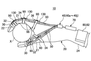
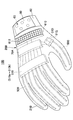
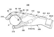
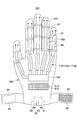
図1は本発明による装着式動作補助装置の実施例1を示す平面図である。図2Aは実施例1の装着式動作補助装置10を側方からみた外観図である。図2Bは実施例1の装着式動作補助装置10を用いて物体Xを把持した動作状態を示す外観図である。図1及び図2Aに示されるように、装着式動作補助装置10は、装着者の各指が挿入される指挿入部21を有する動作補助手袋20からなり、通常の手袋と同様に装着される。動作補助手袋20には、被駆動部30と、駆動部40(40a~40j)と、線状部材50(50a~50j)と、生体信号検出部60と、制御ユニット70とが設けられている。
FIG. 1 is a plan view showing Embodiment 1 of a wearable movement assist device according to the present invention. FIG. 2A is an external view of the wearing-type motion assisting device 10 according to the first embodiment when viewed from the side. FIG. 2B is an external view illustrating an operation state in which the object X is gripped by using the wearable movement assist device 10 according to the first embodiment. As shown in FIGS. 1 and 2A, the wearable movement assist device 10 includes a movement assist glove 20 having a finger insertion portion 21 into which each wearer's finger is inserted, and is worn in the same manner as a normal glove. . The motion assisting glove 20 is provided with a driven unit 30, a driving unit 40 (40a to 40j), a linear member 50 (50a to 50j), a biological signal detection unit 60, and a control unit 70. .
装着式動作補助装置10は、例えば、操作者が手を動作させるための神経系統が麻痺している場合でも、生体信号検出部60によって検出された生体信号に応じて動作補助手袋20の各指挿入部21が駆動されるため、制御ユニット70からの制御信号により各指が伸展方向または屈曲方向に動作するように補助することができる。また、装着式動作補助装置10は、手の指の動作訓練を行なうリハビリ(機能回復訓練)にも用いることができる。
For example, even when the nerve system for the operator to move his / her hand is paralyzed, the wearable motion assisting device 10 is provided with each finger of the motion assisting glove 20 according to the biological signal detected by the biological signal detecting unit 60. Since the insertion portion 21 is driven, each finger can be assisted by a control signal from the control unit 70 to move in the extending direction or the bending direction. The wearable motion assist device 10 can also be used for rehabilitation (function recovery training) for performing hand finger motion training.
動作補助手袋20は、装着者の手に密着するように手のサイズに合わせた立体的な形状に形成されている。また、動作補助手袋20は、外側動作補助手袋と内側動作補助手袋とを一体に縫い込んだ2重構造になっており、例えば、外側動作補助手袋が牛革あるいは合成皮革などの柔軟性と耐久性を有する材質によって形成され、内側動作補助手袋が手の表面(皮膚)に密着するように薄いゴム材により形成されている。
The motion assisting glove 20 is formed in a three-dimensional shape according to the size of the hand so as to be in close contact with the wearer's hand. The motion assisting glove 20 has a double structure in which the outer motion assisting glove and the inner motion assisting glove are sewn together. For example, the outer motion assisting glove has flexibility and durability such as cowhide or synthetic leather. It is formed of a thin rubber material so that the inner motion assisting glove is in close contact with the surface (skin) of the hand.
また、動作補助手袋20の各指挿入部21の指先部分には、装着者の指先を露出させる開口22が設けられている。図2Aに示されるように、装着者は、指先の皮膚を把持する物体に直接触れさせることができるので、指先の感触によって把持する物体Xを認識することが可能になる。
Also, an opening 22 for exposing the wearer's fingertip is provided in the fingertip portion of each finger insertion portion 21 of the motion assisting glove 20. As shown in FIG. 2A, the wearer can directly touch an object that grips the skin of the fingertip, and thus can recognize the object X that is gripped by the touch of the fingertip.
動作補助手袋20の手甲側には、複数の線状部材50(50a~50j)が各指挿入部21の延在方向に沿うように配されている。複数の線状部材50は、一端が動作補助手袋20の各指挿入部21の先端に設けられた被駆動部30に連結されている。複数の線状部材50は、駆動力を伝達する部材であるが、金属部材などに比べて大幅に軽量化されており、装着者の負担も軽減することができる。
A plurality of linear members 50 (50a to 50j) are arranged along the extending direction of each finger insertion portion 21 on the back side of the movement assisting glove 20. One end of each of the plurality of linear members 50 is connected to a driven portion 30 provided at the tip of each finger insertion portion 21 of the motion assisting glove 20. The plurality of linear members 50 are members that transmit driving force, but are significantly lighter than metal members and the like, and can reduce the burden on the wearer.
被駆動部30は、リング状に形成されており、各指挿入部21の先端の外周に密着するように開口22の外側に配されている。また、複数の線状部材50は、指関節に巻き付けられた締結リング32、34、36によって動作補助手袋20の各指挿入部21の外側に締結される。締結リング32、34、36には、各指関節の角度を検出する角度センサ96が保持されている。角度センサ96は、各指関節の角度が変化した場合に、角度変化に応じた検出信号を制御ユニット70に出力する。
The driven part 30 is formed in a ring shape, and is arranged outside the opening 22 so as to be in close contact with the outer periphery of the tip of each finger insertion part 21. Further, the plurality of linear members 50 are fastened to the outside of each finger insertion portion 21 of the motion assisting glove 20 by fastening rings 32, 34, 36 wound around the finger joints. The fastening rings 32, 34, 36 hold an angle sensor 96 that detects the angle of each finger joint. The angle sensor 96 outputs a detection signal corresponding to the angle change to the control unit 70 when the angle of each finger joint changes.
さらに、複数の線状部材50は、動作補助手袋20の各指挿入部21の外側または外側動作補助手袋の内側に縫合される。そのため、複数の線状部材50が、伸展方向または屈曲方向に動作すると共に、動作補助手袋20の各指も線状部材50と一体に伸展方向または屈曲方向に動作する。
Furthermore, the plurality of linear members 50 are stitched to the outside of each finger insertion portion 21 of the operation assisting glove 20 or the inside of the outer operation assisting glove. Therefore, the plurality of linear members 50 operate in the extending direction or the bending direction, and each finger of the operation assisting glove 20 also operates in the extending direction or the bending direction integrally with the linear member 50.
図2A及び図2Bに示されるように、各指挿入部21の各指関節の外側に位置する部分には、付勢部材90が設けられている。付勢部材90としては、例えば、コイルバネまたはゴム材などの弾性部材からなり、一端が指関節に対して手首側に連結され、他端が指関節に対して指先側に連結されている。そのため、動作補助手袋20の各指挿入部21の指関節を覆う表面には、指挿入部21を伸展させようとする付勢部材90の付勢力が付与されており、付勢力が各指関節の伸展動作(図2Bに示す把持状態から図2Aに示す開放状態への動作)の補助力として作用する。
As shown in FIGS. 2A and 2B, a biasing member 90 is provided at a portion of each finger insertion portion 21 located outside each finger joint. The urging member 90 is made of, for example, an elastic member such as a coil spring or rubber material, and one end is connected to the wrist side with respect to the finger joint and the other end is connected to the fingertip side with respect to the finger joint. Therefore, the urging force of the urging member 90 that tries to extend the finger insertion portion 21 is applied to the surface covering the finger joint of each finger insertion portion 21 of the motion assisting glove 20, and the urging force is applied to each finger joint. Acts as an auxiliary force for the extension operation (operation from the gripping state shown in FIG. 2B to the open state shown in FIG. 2A).
尚、付勢部材90は、各指関節を曲げる方向に付勢するように取り付けても良い。このように付勢部材90を取り付ける場合は、付勢部材90が手の平側に配されることになるので、例えば、手の平側に接触した物体の感触が伝わるようにゴム材を扁平状に加工した弾性部材を用いることが望ましい。
The biasing member 90 may be attached so as to bias each finger joint in a bending direction. When the urging member 90 is attached in this way, the urging member 90 is disposed on the palm side, so, for example, the rubber material is processed into a flat shape so that the touch of the object in contact with the palm side is transmitted. It is desirable to use an elastic member.
また、付勢部材90の連結部分には、応力センサ130が設けられている。応力センサ130は、例えば、歪みゲージ等からなり、付勢部材90が指関節の動作に応じて伸縮する際の応力変化に応じた検出信号を制御ユニット70に出力する。
Further, a stress sensor 130 is provided at the connecting portion of the biasing member 90. The stress sensor 130 includes, for example, a strain gauge, and outputs a detection signal corresponding to a change in stress when the biasing member 90 expands and contracts according to the operation of the finger joint to the control unit 70.
駆動部40は、動作補助手袋20の甲側に配置されており、線状部材50を指の関節の動作方向に伸展動作または屈曲動作させる駆動手段であり、例えば、線状部材50の内部に挿通されたワイヤを伸展方向または屈曲方向に移動させる駆動機構40a~40jを有する。本実施例では、各指挿入部21の甲側または側部の両側に線状部材50a~50jが2本ずつ配されており、且つ各指挿入部21毎に駆動機構40a~40jが一対ずつ並列に設けられている。
The driving unit 40 is disposed on the back side of the operation assisting glove 20 and is a driving unit that extends or bends the linear member 50 in the operation direction of the finger joint. For example, the driving unit 40 is provided inside the linear member 50. Drive mechanisms 40a to 40j for moving the inserted wire in the extending direction or the bending direction are provided. In this embodiment, two linear members 50a to 50j are arranged on the back side or both sides of each finger insertion portion 21, and a pair of drive mechanisms 40a to 40j is provided for each finger insertion portion 21. It is provided in parallel.
生体信号検出部60は、複数の生体電位センサ61~65を有し、動作補助手袋20の手首部24の内側に配されている。生体電位センサ61~65は、夫々手の各指を動作させる生体信号(例えば、筋電位信号や神経伝達信号、脳波など)を検出する電極からなる。また、動作補助手袋20の手首部24の両側には、外側から巻き付けて装着者の手に密着させるベルト80、82が設けられている。ベルト80、82には、重なり部分に互いに係止するための面ファスナ84が設けられている。従って、ベルト80、82を動作補助手袋20の手首部24の外側で重ね合わす部分の長さを調整した後、ベルト80、82の面ファスナ84を対向させて生体電位センサ61~65を装着者の皮膚に密着させることができる。生体電位センサ61~65は、装着者が指を動作させようとすることで生体信号を検出し、生体信号に応じた検出信号を出力する。
The biological signal detection unit 60 includes a plurality of bioelectric potential sensors 61 to 65 and is arranged inside the wrist portion 24 of the operation assisting glove 20. The bioelectric potential sensors 61 to 65 are electrodes that detect biological signals (for example, myoelectric potential signals, nerve transmission signals, brain waves, etc.) for operating each finger of each hand. In addition, belts 80 and 82 are provided on both sides of the wrist portion 24 of the motion assisting glove 20 so as to be wound from the outside and brought into close contact with the wearer's hand. The belts 80 and 82 are provided with hook-and-loop fasteners 84 for engaging with each other at the overlapping portions. Accordingly, after adjusting the length of the portion where the belts 80 and 82 are overlapped on the outside of the wrist 24 of the operation assisting glove 20, the bioelectric potential sensors 61 to 65 are attached to the wearer with the surface fasteners 84 of the belts 80 and 82 facing each other. Can be in close contact with the skin. The bioelectric potential sensors 61 to 65 detect a biological signal when the wearer tries to move a finger, and output a detection signal corresponding to the biological signal.
制御ユニット70は、生体信号検出部60の生体電位センサ61~65により検出された生体信号に基づいて演算処理(詳細は後述する)を行なって駆動機構40a~40jへ駆動制御信号を出力する。また、制御ユニット70は、後述するように演算処理を行なう制御部と、メモリと、充電式バッテリと有する。
The control unit 70 performs arithmetic processing (details will be described later) based on the biological signals detected by the biological potential sensors 61 to 65 of the biological signal detection unit 60, and outputs drive control signals to the drive mechanisms 40a to 40j. The control unit 70 includes a control unit that performs arithmetic processing, a memory, and a rechargeable battery as will be described later.
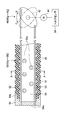
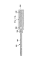
ここで、線状部材50及び駆動部40の構成について説明する。図3Aは線状部材50及び駆動部40の構成を模式的に示す図である。図3Aに示されるように、線状部材50は、筒状体51と、ワイヤ52、53と、キャップ54と有する。筒状体51は、可撓性を有する樹脂材により筒状に成形されている。また、筒状体51は、内側にワイヤ52、53が挿通される中空部55が形成され、外側には伸展動作または屈曲動作に応じて伸縮する凹部と凸部とが交互に連続する蛇腹状部56が形成されている。
Here, the configuration of the linear member 50 and the drive unit 40 will be described. FIG. 3A is a diagram schematically illustrating the configuration of the linear member 50 and the drive unit 40. As shown in FIG. 3A, the linear member 50 includes a cylindrical body 51, wires 52 and 53, and a cap 54. The cylindrical body 51 is formed into a cylindrical shape from a flexible resin material. Further, the cylindrical body 51 has a bellows shape in which a hollow portion 55 into which the wires 52 and 53 are inserted is formed on the inner side, and a concave portion and a convex portion that are expanded and contracted in response to an extending operation or a bending operation are alternately arranged on the outer side. A portion 56 is formed.
さらに、筒状体51の先端で中空部55に連通された開口は、キャップ54による閉塞されている。キャップ54は、金属材により形成されており、壁部54aには各ワイヤ52、53の一端が挿通され、且つ溶着により一体的に結合されている。また、キャップ54の周縁部54bは、筒状体51の端部と接着または溶着されて一体化されている。
Furthermore, the opening communicated with the hollow portion 55 at the tip of the cylindrical body 51 is closed by a cap 54. The cap 54 is formed of a metal material, and one end of each of the wires 52 and 53 is inserted into the wall portion 54a and integrally joined by welding. Further, the peripheral edge 54 b of the cap 54 is bonded or welded to the end of the cylindrical body 51 and integrated.
図3Bは図3A中A-A線に沿う縦断面図である。図3Bに示されるように、筒状体51の断面形状は、四角形からなる矩形であり、中空部55に横架された複数の横架部材55aにより、上部空間57と、下部空間58と、中部空間59とに仕切られている。
FIG. 3B is a longitudinal sectional view taken along line AA in FIG. 3A. As shown in FIG. 3B, the cross-sectional shape of the cylindrical body 51 is a rectangular rectangle, and an upper space 57, a lower space 58, and a plurality of horizontal members 55a horizontally mounted on the hollow portion 55, It is partitioned into a middle space 59.
上部空間57には、2本のワイヤ52が装架されており、下部空間58には、2本のワイヤ53が装架されている。本実施例では、合計4本のワイヤ52、53が筒状体51に上下対称となるように配置されている。また、筒状体51の外観形状が四角形であるので、下面を動作補助手袋20の外面に当接させることにより、動作方向に合わせて位置決めすることが可能になる。
In the upper space 57, two wires 52 are mounted, and in the lower space 58, two wires 53 are mounted. In the present embodiment, a total of four wires 52 and 53 are arranged so as to be vertically symmetrical with respect to the cylindrical body 51. Moreover, since the external shape of the cylindrical body 51 is a quadrangle, it is possible to position the lower body in accordance with the operation direction by bringing the lower surface into contact with the outer surface of the operation assisting glove 20.
図3Aに示されるように、各ワイヤ52、53の他端は、駆動部40の回動部材42に連結されている。本実施例の回動部材42は、楕円形状に形成されており、長径部の周縁部の最も離間した位置に各ワイヤ52、53の他端が連結されている。尚、2本ずつ配された各ワイヤ52、53は、一つの回動部材42の両面に連結されているので、回動部材42の回動角度に応じて同時に動作する。さらに、回動部材42の中心部を貫通する軸は、電動モータ44の出力軸に連結されている。そのため、駆動部40は、回動部材42の回動方向を切替えるように回動させることで、ワイヤ52とワイヤ53とを逆方向に移動させることで駆動力を動作補助手袋20の各指挿入部21に効率良く伝達することができる。ワイヤ52、53のうち引張り力が作用する方が指挿入部21を動作させる駆動力を伝達する伝達部材として動作する。尚、モータ44の出力軸の他端には、モータトルクを検出するトルクセンサ94が設けられている。
As shown in FIG. 3A, the other ends of the wires 52 and 53 are connected to the rotating member 42 of the drive unit 40. The rotating member 42 of the present embodiment is formed in an elliptical shape, and the other ends of the wires 52 and 53 are connected to the farthest positions on the peripheral edge of the long diameter portion. Since the two wires 52 and 53 arranged in two are connected to both surfaces of one rotating member 42, they operate simultaneously according to the rotating angle of the rotating member 42. Further, the shaft passing through the central portion of the rotating member 42 is connected to the output shaft of the electric motor 44. Therefore, the drive unit 40 is rotated so as to switch the rotation direction of the rotation member 42, thereby moving the wire 52 and the wire 53 in the opposite directions to thereby apply the driving force to each finger of the operation assisting glove 20. It is possible to efficiently transmit to the unit 21. Of the wires 52 and 53, the one on which the tensile force acts operates as a transmission member that transmits the driving force that operates the finger insertion portion 21. A torque sensor 94 that detects motor torque is provided at the other end of the output shaft of the motor 44.
例えば、回動部材42が時計方向(B方向)に回動した場合は、上側のワイヤ52が引張り方向に動作し、下側のワイヤ53が戻し方向に動作する。これにより、線状部材50は、筒状体51が直線状に戻るように動作する。そのため、線状部材50の伸展動作は、動作補助手袋20の各指挿入部21に伝達され、装着者の各指を開いた状態(図1及び図2A参照)に動作させることができる。
For example, when the rotating member 42 rotates clockwise (B direction), the upper wire 52 operates in the pulling direction and the lower wire 53 operates in the returning direction. Thereby, the linear member 50 operates so that the cylindrical body 51 returns to a linear shape. Therefore, the extending operation of the linear member 50 is transmitted to each finger insertion portion 21 of the operation assisting glove 20, and can be operated in a state where each finger of the wearer is opened (see FIGS. 1 and 2A).
また、図3A中、一点鎖線で示すように、回動部材42が反時計方向(C方向)に回動した場合は、上側のワイヤ52が戻り方向に動作し、下側のワイヤ53が引張り方向に動作する。これにより、図3Cに示されるように、線状部材50の筒状体51は、屈曲した状態に動作する。そのため、線状部材50の屈曲動作は、動作補助手袋20の各指挿入部21に伝達され、装着者の各指を把持状態(図2B参照)に動作させることができる。
3A, when the rotating member 42 rotates counterclockwise (C direction), the upper wire 52 operates in the return direction, and the lower wire 53 pulls. Operate in the direction. Thereby, as FIG. 3C shows, the cylindrical body 51 of the linear member 50 operate | moves in the bent state. Therefore, the bending operation of the linear member 50 is transmitted to each finger insertion portion 21 of the operation assisting glove 20, and each finger of the wearer can be operated in a gripping state (see FIG. 2B).
本実施例においては、上記ワイヤ52、53を伸展方向または屈曲方向に駆動する際のストローク(動作距離)は、楕円形に形成された回動部材42の長径寸法によって決まるので、回動部材42の長径寸法を大きくすることにより、線状部材50の屈曲動作から伸展動作までのストロークを大きく設定することも可能である。また、回動部材42の代わりにギヤ機構及びワイヤ52、53を巻き取るプーリ等の駆動機構を設けて、プーリの回転量を調整することにより線状部材50の動作ストロークを適宜調整することも可能である。
In this embodiment, the stroke (operation distance) when driving the wires 52 and 53 in the extending direction or the bending direction is determined by the major axis dimension of the rotating member 42 formed in an elliptical shape. It is also possible to increase the stroke from the bending operation to the extending operation of the linear member 50 by increasing the major axis dimension of the linear member 50. Further, instead of the rotating member 42, a gear mechanism and a driving mechanism such as a pulley for winding the wires 52 and 53 may be provided, and the operation stroke of the linear member 50 may be appropriately adjusted by adjusting the rotation amount of the pulley. Is possible.
このように、装着式動作補助装置10は、制御ユニット70からの駆動制御信号に基づいて線状部材50を指挿入部21の関節の動作方向に伸展または屈曲させることにより、装着者の指の関節を動作させるように駆動部40の駆動力を伝達することができるので、軽量化を図ることができると共に、装着者の負担を軽減することが可能になる。
As described above, the wearable movement assisting device 10 extends or bends the linear member 50 in the direction of movement of the joint of the finger insertion unit 21 based on the drive control signal from the control unit 70, thereby Since the driving force of the driving unit 40 can be transmitted so as to operate the joint, the weight can be reduced and the burden on the wearer can be reduced.
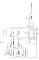
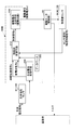
図4は制御ユニット70を含む制御系及び充電システムの概略構成を模式的に示す図である。図4に示されるように、制御ユニット70は、制御部100と、メモリ102と、表示器104と、充電式バッテリ124とを有する。
FIG. 4 is a diagram schematically showing a schematic configuration of a control system including the control unit 70 and a charging system. As shown in FIG. 4, the control unit 70 includes a control unit 100, a memory 102, a display 104, and a rechargeable battery 124.
制御部100には、生体電位センサ61~65により検出された生体信号、トルクセンサ94により検出された電動モータ44のトルク検出信号、及び角度センサ96により検出された各指関節の角度検出信号、及び応力センサ130により検出された応力検出信号が入力される。制御部100は、メモリ102に格納された各制御プログラム及び各パラメータを読み込むと共に、トルクセンサ94、角度センサ96、応力センサ130からの検出信号に基づいて演算処理を行なって動作補助手袋20の動作状態を表示器104に表示する。充電式バッテリ124は、充電ユニット122の2次コイル126に接続されており、充電器140により定期的に充電される。
The control unit 100 includes a biological signal detected by the bioelectric potential sensors 61 to 65, a torque detection signal of the electric motor 44 detected by the torque sensor 94, and an angle detection signal of each finger joint detected by the angle sensor 96, And a stress detection signal detected by the stress sensor 130 is input. The control unit 100 reads each control program and each parameter stored in the memory 102 and performs arithmetic processing based on detection signals from the torque sensor 94, the angle sensor 96, and the stress sensor 130 to operate the auxiliary assisting glove 20. The status is displayed on the display unit 104. The rechargeable battery 124 is connected to the secondary coil 126 of the charging unit 122 and is periodically charged by the charger 140.
充電器140は、2次コイル126に電磁誘導電流を発生させる1次コイル142を有する。そのため、1次コイル142を動作補助手袋20に近接させることにより、電磁誘導により充電ユニット122の2次コイル126に2次電流を発生させる。これにより、動作補助手袋20の充電式バッテリ124は、装着状態のまま充電することが可能になっており、装着者が使用していても充電可能である。
The charger 140 has a primary coil 142 that generates an electromagnetic induction current in the secondary coil 126. Therefore, a secondary current is generated in the secondary coil 126 of the charging unit 122 by electromagnetic induction by bringing the primary coil 142 close to the operation assisting glove 20. Thereby, the rechargeable battery 124 of the operation assisting glove 20 can be charged while being worn, and can be charged even if the wearer is using it.
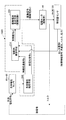
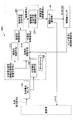
図5は実施例1の制御部100のシステム系統図である。図5に示されるように、制御部100Aは、図4に示す制御部100の一例であり、メモリ102から制御プログラムを読み込むことにより後述する各制御処理を実行するコンピュータからなる。
FIG. 5 is a system diagram of the control unit 100 according to the first embodiment. As shown in FIG. 5, the control unit 100 </ b> A is an example of the control unit 100 shown in FIG. 4, and includes a computer that executes each control process described later by reading a control program from the memory 102.
本実施例において、制御部100Aは、生体電位センサ61~65により検出された生体電位から指令信号を取得する生体電位処理手段(生体信号処理手段)200と、神経伝達信号bおよび筋電位信号cに基づいて電動モータ44の駆動を制御する随意的制御手段212と、随意的制御手段212から出力された制御信号に応じた駆動電流を電動モータ44に供給する駆動電流生成手段220とを有する。
In the present embodiment, the control unit 100A includes a biopotential processing means (biological signal processing means) 200 that acquires a command signal from the biopotentials detected by the biopotential sensors 61 to 65, a nerve transmission signal b, and a myoelectric potential signal c. And an optional control means 212 for controlling the driving of the electric motor 44 and a drive current generating means 220 for supplying a drive current corresponding to the control signal output from the optional control means 212 to the electric motor 44.
随意的制御手段212は、後述するように、装着者の意思により各指を動作させる際に生じる生体電位信号aから神経伝達信号bおよび筋電位信号cを生成する生体電位処理手段200からの指令信号に基づいて制御信号を駆動電流生成手段220に出力する。駆動電流生成手段220は、随意的制御手段212からの制御信号に応じた駆動電流を生成して電動モータ44に出力する。
As will be described later, the optional control means 212 is a command from the biopotential processing means 200 that generates the nerve transmission signal b and the myoelectric potential signal c from the biopotential signal a generated when each finger is operated by the wearer's intention. Based on the signal, a control signal is output to the drive current generator 220. The drive current generation unit 220 generates a drive current according to the control signal from the optional control unit 212 and outputs it to the electric motor 44.
生体電位センサ61~65は、上腕の内部で発生する生体電位信号aを検出して生体電位処理手段200に入力する。生体電位処理手段200は、生体電位信号aから神経伝達信号bおよび筋電位信号cを抽出して随意的制御手段212に入力する。随意的制御手段212は、装着者の意思で動作補助手袋20が装着された手の各指を動作させる際に生じる生体電位信号aから得られた神経伝達信号bおよび筋電位信号cに基づいて随意的制御信号d1を生成する。
The biopotential sensors 61 to 65 detect the biopotential signal a generated inside the upper arm and input it to the biopotential processing means 200. The biopotential processing means 200 extracts the nerve transmission signal b and the myoelectric potential signal c from the biopotential signal a and inputs them to the optional control means 212. The optional control means 212 is based on the nerve transmission signal b and the myoelectric potential signal c obtained from the bioelectric potential signal a generated when each finger of the hand wearing the operation assisting glove 20 is operated at the intention of the wearer. An optional control signal d1 is generated.
すなわち、随意的制御手段212は、生体電位信号aに含まれる神経伝達信号bおよび筋電位信号cを用い、装着者の意思に従った動力を電動モータ44に発生させるための随意的制御信号d1を生成する。随意的制御手段212での制御則としては、比例制御を適用することができる。比例制御により随意的制御信号d1と駆動電流eとが比例関係になる。さらに、電動モータ44の特性により駆動電流値と電動モータ44の発生トルク値とが比例関係になる。尚、随意的制御手段212での制御則としては、比例制御と微分制御および/または積分制御とを組み合わせたものを適用しても良い。
That is, the optional control means 212 uses the nerve transmission signal b and the myoelectric potential signal c included in the bioelectric potential signal a, and the optional control signal d1 for causing the electric motor 44 to generate power according to the wearer's intention. Is generated. As a control law in the optional control means 212, proportional control can be applied. By the proportional control, the optional control signal d1 and the drive current e are in a proportional relationship. Further, the drive current value and the generated torque value of the electric motor 44 are proportional to each other due to the characteristics of the electric motor 44. As a control law in the optional control means 212, a combination of proportional control, differential control and / or integral control may be applied.
例えば、装着者が関節20を動作させようとすると、生体電位センサ61~65は指を動作させる生体電位を直接的に検出し、検出された生体電位に応じた生体電位aを生体電位処理手段200に出力する。このように、生体電位センサ61~65は、生体電位信号aを動作補助手袋22の手首部24がベルト80、82の締付けにより密着する装着者の手首から直接検出するため、検出精度が高く、微弱な信号でも正確に検出することが可能である。
For example, when the wearer tries to operate the joint 20, the biopotential sensors 61 to 65 directly detect the biopotential for operating the finger, and the biopotential a corresponding to the detected biopotential is biopotential processing means. Output to 200. In this way, the biopotential sensors 61 to 65 detect the biopotential signal a directly from the wrist of the wearer where the wrist portion 24 of the operation assisting glove 22 comes into close contact with the belts 80 and 82, and thus has high detection accuracy. Even weak signals can be accurately detected.
生体電位処理手段200から神経伝達信号bと筋電位信号cとからなる指令信号を入力された随意的制御手段212は、神経伝達信号bと筋電位信号cから制御信号d1を生成して駆動電流生成手段220に出力する。
The optional control means 212, which receives the command signal composed of the nerve transmission signal b and the myoelectric potential signal c from the bioelectric potential processing means 200, generates the control signal d1 from the nerve transmission signal b and the myoelectric potential signal c and generates a drive current. Output to the generation means 220.
駆動電流生成手段220は、随意的制御手段212からの制御信号dに基づいてモータ駆動電流eを生成して電動モータ44に供給する。これにより、電動モータ44は、モータ駆動電流eの供給により回動部材42を伸展方向または屈曲方向に回動させる。そのため、動作補助手袋20の線状部材50が伸展動作または屈曲動作するように筒状体51の中空部55に装架されたワイヤ52、53を移動させる。
The drive current generation means 220 generates a motor drive current e based on the control signal d from the optional control means 212 and supplies it to the electric motor 44. Thereby, the electric motor 44 rotates the rotating member 42 in the extending direction or the bending direction by supplying the motor driving current e. Therefore, the wires 52 and 53 mounted on the hollow portion 55 of the cylindrical body 51 are moved so that the linear member 50 of the motion assisting glove 20 performs an extending operation or a bending operation.
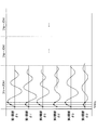
図6は生体電位信号から各制御信号を生成する過程を示す図である。図6に示されるように、生体電位センサ61~65により検出された生体電位信号aは、神経伝達信号bおよび筋電位信号cを有する。神経伝達信号bは意思伝達信号とも言えるもので、筋電位信号の先頭領域と重なっている。神経伝達信号bの周波数は、一般に筋電位信号cの周波数より高いので、異なるバンドパスフィルタを用いることにより分離することができる。
FIG. 6 is a diagram showing a process of generating each control signal from the biopotential signal. As shown in FIG. 6, the bioelectric potential signal a detected by the bioelectric potential sensors 61 to 65 has a nerve transmission signal b and a myoelectric potential signal c. The nerve transmission signal b can be said to be an intention transmission signal, and overlaps the leading region of the myoelectric potential signal. Since the frequency of the nerve transmission signal b is generally higher than the frequency of the myoelectric potential signal c, it can be separated by using different bandpass filters.
神経伝達信号bは、生体電位信号aを増幅器202により増幅した後、例えば33Hz~数KHzの高帯域バンドパスフィルタ204により取り出すことができる。また、筋電位信号cは、生体電位信号aを増幅器202により増幅した後、例えば33Hz~500Hzの中帯域バンドパスフィルタ206により取り出すことができる。尚、図5において、各フィルタ204、206は並列に接続されているがこれに限定されず、両フィルタ204、206が直列に接続されていても良い。
The nerve transmission signal b can be extracted by, for example, the high band-pass filter 204 of 33 Hz to several KHz after the bioelectric potential signal a is amplified by the amplifier 202. Further, the myoelectric potential signal c can be taken out by, for example, the 33 Hz to 500 Hz middle band bandpass filter 206 after the bioelectric potential signal a is amplified by the amplifier 202. In FIG. 5, the filters 204 and 206 are connected in parallel. However, the present invention is not limited to this, and both filters 204 and 206 may be connected in series.
また、神経伝達信号bは、筋電位信号cの先頭領域のみならず、先頭領域以降についても重なる場合が有り得る。この場合には、神経伝達信号bの先頭領域のみを後述するパルス電流の生成に利用するようにすれば良い。
In addition, the nerve transmission signal b may overlap not only in the head region of the myoelectric potential signal c but also in the head region and the subsequent regions. In this case, only the head region of the nerve transmission signal b may be used for generating a pulse current described later.
神経伝達信号bおよび筋電位信号cには、スムージング処理(ノイズを除去する平滑処理)を行う。各電流は、生体信号処理手段200からの信号をスムージングして得た制御信号を入力とし、駆動電流生成手段220によって生成される。
Smoothing processing (smoothing processing for removing noise) is performed on the nerve transmission signal b and the myoelectric potential signal c. Each current is generated by the drive current generation means 220 with a control signal obtained by smoothing the signal from the biological signal processing means 200 as an input.
神経伝達信号bは、時間軸上の幅が狭いので、スムージング処理だけでもパルス状となり、当該神経伝達信号bに基づいて駆動電流生成手段220によって生成される電流もパルス状となる。尚、神経伝達信号bに基づいて得られる電流(パルス電流)e1は、矩形波状となる。一方、筋電位信号cは、時間軸上の幅が広いので、スムージング処理することにより実質的に筋電位に比例する山状となり、当該筋電位信号cに基づいて駆動電流生成手段220によって生成される電流e2も山状となる。
Since the nerve transmission signal b has a narrow width on the time axis, the smoothing process alone is pulsed, and the current generated by the drive current generator 220 based on the nerve transmission signal b is also pulsed. The current (pulse current) e1 obtained based on the nerve transmission signal b has a rectangular wave shape. On the other hand, since the myoelectric potential signal c has a wide width on the time axis, it becomes a mountain shape that is substantially proportional to the myoelectric potential by performing the smoothing process, and is generated by the drive current generating means 220 based on the myoelectric potential signal c. The current e2 is also mountain-shaped.
神経伝達信号bに基づいて生成されるパルス電流e1と、筋電位信号cに基づいて比例的に生成される電流e2との総電流(随意的制御信号)eが電動モータ44に供給されると、当該総電流eに比例する大きさのトルクを電動モータ44が発生する。電動モータ44に入力される各電流e、e1、e2の大きさは、装着者の動作時の感覚により適宜設定される。
When a total current (optional control signal) e of a pulse current e1 generated based on the nerve transmission signal b and a current e2 generated proportionally based on the myoelectric potential signal c is supplied to the electric motor 44. The electric motor 44 generates a torque having a magnitude proportional to the total current e. The magnitudes of the currents e, e1, e2 input to the electric motor 44 are appropriately set according to the sense of the wearer during operation.
ここで、総電流eは十分に大きな電流に設定してあるので、装着者の動作意思に遅れなく電動モータ44が駆動され、装着者は自分の意思に従った各指関節の動作を違和感なく行うことができる。尚、パルス電流e1を特に大きく示しているが、これはその役割を強調するためで、実際のパルス電流と筋電位信号から得られた駆動電流e2との関係を示すものではない。
Here, since the total current e is set to a sufficiently large current, the electric motor 44 is driven without a delay from the wearer's intention to operate, and the wearer feels uncomfortable about the operation of each finger joint according to his / her intention. It can be carried out. Note that the pulse current e1 is shown particularly large, but this is for emphasizing its role, and does not show the relationship between the actual pulse current and the drive current e2 obtained from the myoelectric potential signal.
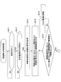
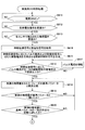
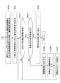
ここで、図5に示す上記制御システムにおける制御部100Aが実行する制御処理の手順について図7A及び図7Bのフローチャートを参照して説明する。制御部100Aは、メモリ102に格納された制御プログラムを読み込んで図7の制御処理を実行する。
Here, the procedure of the control process executed by the control unit 100A in the control system shown in FIG. 5 will be described with reference to the flowcharts of FIGS. 7A and 7B. The control unit 100A reads the control program stored in the memory 102 and executes the control process of FIG.
図7AのSA11において、制御ユニット70の電源スイッチがオンに操作されると、SA12に進み、生体電位センサ61~65によって検出された生体電位信号aが受信されたか否かをチェックする。ここで、装着者が自らの意思で各指関節を動作させようとすると、生体電位センサ61~65により生体電位信号aが検出されるため、SA13の処理に進む。
7A, when the power switch of the control unit 70 is turned on in SA11, the process proceeds to SA12 to check whether or not the bioelectric potential signal a detected by the bioelectric potential sensors 61 to 65 has been received. Here, when the wearer tries to operate each finger joint with his / her own intention, the biopotential signal a is detected by the biopotential sensors 61 to 65, and the process proceeds to SA13.
SA13では、生体電位センサ61~65により検出した生体電位信号aから神経伝達信号bおよび筋電位信号cを取得する(生体電位処理手段)。続いて、SA14に進み、神経伝達信号bに基づいてパルス電流e1を生成し、且つ筋電位信号cに基づいて電流e2を生成する(駆動電流生成手段)。
In SA13, the nerve transmission signal b and the myoelectric potential signal c are acquired from the biopotential signal a detected by the biopotential sensors 61 to 65 (biopotential processing means). Subsequently, the process proceeds to SA14, where a pulse current e1 is generated based on the nerve transmission signal b, and a current e2 is generated based on the myoelectric potential signal c (drive current generating means).
次のSA15では、神経伝達信号bに応じたパルス電流e1が電動モータ44の駆動開始可能電流の下限値It以上か否かをチェックする。当該SA15において、パルス電流e1が電動モータ44の駆動開始可能電流の下限値It以上でない場合(NOの場合)、SA16に進み、パルス電流e1が駆動開始可能電流の下限値It以上になるように、パルス電流e1を増幅する。
In the next SA15, it is checked whether or not the pulse current e1 corresponding to the nerve transmission signal b is equal to or greater than the lower limit value It of the electric motor 44 startable drive current. In SA15, when the pulse current e1 is not equal to or greater than the lower limit value It of the drive startable current of the electric motor 44 (in the case of NO), the process proceeds to SA16 so that the pulse current e1 becomes equal to or greater than the lower limit value It of the drive startable current. The pulse current e1 is amplified.
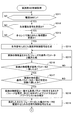
また、SA15において、パルス電流e1が電動モータ44の駆動開始可能電流の下限値It以上の場合(YESの場合)、図7BのSA17に進み、パルス電流e1に応じた指令信号を生成する。続いて、SA18では、筋電位信号cに基づく駆動電流e2を電動モータ44に出力する。これで、動作補助手袋20の各線状部材50は、伸展動作または屈曲動作を行なう。
Also, in SA15, when the pulse current e1 is equal to or greater than the lower limit value It of the drive startable current of the electric motor 44 (in the case of YES), the process proceeds to SA17 in FIG. 7B, and a command signal corresponding to the pulse current e1 is generated. Subsequently, in SA18, the drive current e2 based on the myoelectric potential signal c is output to the electric motor 44. Thus, each linear member 50 of the motion assisting glove 20 performs an extending operation or a bending operation.
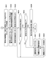
次のSA19では、動作補助手袋20の各線状部材50の動作に伴って各指関節が動作すると共に、トルクセンサ94、角度センサ96、応力センサ130(物理量センサ)のセンサ信号fを受信したか否かをチェックする。
In the next SA19, each finger joint is operated in accordance with the operation of each linear member 50 of the operation assisting glove 20, and the sensor signal f of the torque sensor 94, the angle sensor 96, and the stress sensor 130 (physical quantity sensor) is received. Check whether or not.
続いて、SA20に進み、電動モータ44の駆動力による各指関節の動作に伴って応力センサ130により検出された検出応力が予め設定された許容値以下か否かをチェックする。当該許容値は、付勢部材90の付勢力の強さに応じて選択的に設定されている。これにより、電動モータ44の駆動力が指関節を無理に動作させないように制御しており、電動モータ44の駆動力による指関節の損傷を防止する。
Subsequently, the process proceeds to SA20, and it is checked whether or not the detected stress detected by the stress sensor 130 with the operation of each finger joint by the driving force of the electric motor 44 is equal to or less than a preset allowable value. The permissible value is selectively set according to the strength of the urging force of the urging member 90. Thus, the driving force of the electric motor 44 is controlled so as not to force the finger joint to operate, and the finger joint is prevented from being damaged by the driving force of the electric motor 44.
従って、SA20において、応力センサ130により検出された各指関節の検出応力が予め設定された許容値以下の場合(YESの場合)、SA21に進み、各物理量センサ(トルクセンサ94、角度センサ96、応力センサ130)の検出値(物理情報)及び生体電位信号を表示器104に表示させる。これにより、装着者は、表示器104の表示から各指関節の動作状態(各線状部材50による駆動力及び駆動方向)を認識することが可能になる。
Accordingly, in SA20, when the detected stress of each finger joint detected by the stress sensor 130 is equal to or smaller than a preset allowable value (in the case of YES), the process proceeds to SA21 and each physical quantity sensor (torque sensor 94, angle sensor 96, The detection value (physical information) of the stress sensor 130) and the bioelectric potential signal are displayed on the display 104. Accordingly, the wearer can recognize the operation state of each finger joint (the driving force and the driving direction by each linear member 50) from the display on the display unit 104.
また、上記SA20において、応力センサ130により検出された各指関節の検出応力が予め設定された許容値以上の場合(YESの場合)、SA22に進み、電動モータ44に供給される駆動電流eを例えば、10%下げる。尚、駆動電流eの下げ幅は、任意の値に設定することが可能であり、例えば、1~10%の範囲内で設定変更することができる。
In SA20, when the detected stress of each finger joint detected by the stress sensor 130 is equal to or larger than a preset allowable value (in the case of YES), the process proceeds to SA22 and the drive current e supplied to the electric motor 44 is set. For example, decrease by 10%. Note that the amount of decrease in the drive current e can be set to an arbitrary value, and can be changed within a range of 1 to 10%, for example.
そして、SA23では、上記のように制限された駆動電流を電動モータ44に出力する。これにより、電動モータ44は各指関節の強度を超えないように制限されたトルク、回転角を発生させるように制御される。
In SA23, the drive current limited as described above is output to the electric motor 44. Thereby, the electric motor 44 is controlled to generate a torque and a rotation angle that are limited so as not to exceed the strength of each finger joint.
続いて、SA24に進み、制限された駆動電流のデータを表示器104に表示させる。この後は、上記SA19に戻り、各指関節の動作に伴って各物理量センサ(トルクセンサ94、角度センサ96、応力センサ130)のセンサ信号fを受信したか否かをチェックしてSA19以降の処理を行なう。
Subsequently, the process proceeds to SA24, and the limited drive current data is displayed on the display unit 104. Thereafter, the process returns to SA19, where it is checked whether the sensor signal f of each physical quantity sensor (torque sensor 94, angle sensor 96, stress sensor 130) has been received in accordance with the operation of each finger joint. Perform processing.
SA19、SA20、SA22~SA24の制御処理を繰り返すことにより、電動モータ44の駆動力が許容値以下となるように制御して過剰なトルクが伝達されることを防止する。
By repeating the control processing of SA19, SA20, SA22 to SA24, the driving force of the electric motor 44 is controlled to be less than the allowable value to prevent excessive torque from being transmitted.
当該SA11~SA24の処理は、制御ユニット70の電源スイッチがオフになるまで繰り返し実行される。これにより、電動モータ44は、装着者の意思に応じた動作を行なうように駆動制御される。
The processing of SA11 to SA24 is repeatedly executed until the power switch of the control unit 70 is turned off. Thereby, the electric motor 44 is drive-controlled to perform an operation according to the wearer's intention.
図8は実施例2の制御部100Bの信号処理を模式的に示すシステム系統図である。尚、図8において、前述した実施例1の図4と同一部分には同一符号を付してその説明を省略する。
FIG. 8 is a system diagram schematically showing signal processing of the control unit 100B of the second embodiment. In FIG. 8, the same parts as those in FIG. 4 of the first embodiment are denoted by the same reference numerals, and the description thereof is omitted.
図8に示す実施例2の制御部100Bは、生体電位処理手段200、随意的制御手段212、データベース300、駆動電流生成手段220を有する。尚、動作補助手袋20は、前述した実施例1と同じ構成であるので、その説明を省略する。また、図8の制御部100Bは、図3の制御部100の一例である。
8 includes a biopotential processing means 200, an optional control means 212, a database 300, and a drive current generating means 220. In addition, since the operation assistance glove 20 is the same structure as Example 1 mentioned above, the description is abbreviate | omitted. Further, the control unit 100B in FIG. 8 is an example of the control unit 100 in FIG.
制御部100Bのデータベース300は、装着者の各指関節の回転角及び角速度等を、全タスクの全フェーズについて経験的に求め、それらの基準パラメータ(基準の回転角及び角速度等)を格納している。そして、随意的制御手段212は、動作補助手袋20(図1乃至図3を参照)の電動モータ44の随意的制御を行う際、装着者の各指関節の動作に関する物理量からデータベース300からタスク及びフェーズを推定し、推定したフェーズに対応するパワーアシスト率となるように駆動力を電動モータ44に発生させる。
The database 300 of the control unit 100B obtains the rotation angle and angular velocity of each finger joint of the wearer empirically for all phases of all tasks, and stores those reference parameters (reference rotation angle and angular velocity, etc.). Yes. Then, the optional control means 212 performs tasks from the database 300 based on physical quantities related to the operation of each finger joint of the wearer when performing optional control of the electric motor 44 of the motion assisting glove 20 (see FIGS. 1 to 3). The phase is estimated, and the driving force is generated in the electric motor 44 so that the power assist rate corresponding to the estimated phase is obtained.
ここで、上記タスク(Task)およびそのフェーズ(Phase)について説明する。タスクとは装着者の各指関節の動作パターンを分類したもので、フェーズは各タスクを構成する一連の最小動作単位である。
Here, the task (Task) and its phase (Phase) will be described. A task is a classification of movement patterns of each finger joint of the wearer, and a phase is a series of minimum movement units constituting each task.
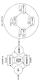
図9は、各指の基本動作として、指を伸ばす(タスクA)、物を把持(タスクB)、指を曲げる(タスクC)、および握手(タスクD)を模式的に例示する図である。尚、本実施例では図1~3に示されるように、装着者に動作補助手袋20を実装した場合について説明しているが、ここでは、説明の便宜上、上記各指の動作を例に挙げて説明する。
FIG. 9 is a diagram schematically illustrating as a basic operation of each finger, extending a finger (task A), grasping an object (task B), bending a finger (task C), and shaking hands (task D). . In this embodiment, as shown in FIGS. 1 to 3, the case where the operation assisting glove 20 is mounted on the wearer is described, but here, for convenience of explanation, the operation of each finger is given as an example. I will explain.
図9において、各タスクは上記フェーズからなり、例えば物を把持するタスクBは、各指が揃ったフェーズB1と、各指の第1関節が曲げられたフェーズB2と、各指の第1、第2関節が曲げられたフェーズB3と、各指の第1、第2、第3関節が曲げられたフェーズB4からなる。
In FIG. 9, each task consists of the above phases. For example, task B for grasping an object includes phase B1 in which each finger is aligned, phase B2 in which the first joint of each finger is bent, and the first, It consists of a phase B3 in which the second joint is bent and a phase B4 in which the first, second and third joints of each finger are bent.
このような一連のフェーズB1~B4をフェーズ・シークエンス(Phase Sequence)という。装着者の各指関節動作を補助するのに適切な動力はフェーズ毎に異なる。そのため、各フェーズによって異なるパワーアシスト率PAR1、PAR2、PAR3、PAR4を付与することにより、フェーズ毎に最適な動作補助を行うことができる。
Such a series of phases B1 to B4 is referred to as a phase sequence. The appropriate power for assisting the wearer's finger joint movement varies from phase to phase. Therefore, by providing different power assist rates PAR1, PAR2, PAR3, and PAR4 depending on each phase, optimal operation assistance can be performed for each phase.
装着者の各指関節の動きを分析すると、各フェーズにおける各指関節の回転角及び角速度、動作速度及び加速度等が決まっていることが分かる。例えば、装着者の典型的な指動作パターンは決まっており、その動作パターンで動作補助手袋20を動作させるときに最も自然に感じる。従って、装着者の各指関節の回転角及び角速度等を、全タスクの全フェーズについて経験的に求め、それらを基準パラメータ(基準の回転角及び角速度等)としてデータベース300に格納しておけば良い。
When analyzing the movement of each finger joint of the wearer, it can be seen that the rotation angle and angular velocity, motion speed, acceleration, etc. of each finger joint in each phase are determined. For example, a typical finger movement pattern of the wearer is determined, and it feels most natural when the movement assisting glove 20 is operated with the movement pattern. Therefore, the rotation angle and angular velocity of each finger joint of the wearer are obtained empirically for all phases of all tasks and stored in the database 300 as reference parameters (reference rotation angle and angular velocity, etc.). .
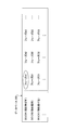
図10Aはデータベース300に格納されている各タスク及び各フェーズを模式的に示す図である。図10Bは、物理量を基準パラメータと比較することにより装着者が行おうとしているタスク、およびその中のフェーズを推定するプロセスを模式的に示す図である。図10A、図10Bに示すタスクおよびフェーズは、図9に示すものである。例示したタスクA、タスクB、タスクC・・・は、それぞれ、一連のフェーズ(フェーズA1、フェーズA2、フェーズA3・・・、フェーズB1、フェーズB2、フェーズB3・・・等)により構成されている。
FIG. 10A is a diagram schematically showing each task and each phase stored in the database 300. FIG. 10B is a diagram schematically illustrating a task that a wearer is going to perform by comparing a physical quantity with a reference parameter, and a process for estimating a phase therein. The tasks and phases shown in FIGS. 10A and 10B are as shown in FIG. The illustrated task A, task B, task C... Is composed of a series of phases (phase A1, phase A2, phase A3..., Phase B1, phase B2, phase B3...), Respectively. Yes.
装着者が各指関節の動作を開始すると、物理量センサとしての角度センサ96、応力センサ130で検出されたセンサ信号により得られた各種の物理量の実測値をデータベース300に格納された基準パラメータと比較する。当該比較は、図10B中のグラフで概略的に示す。当該グラフでは、各指の第1関節の回転角θ1および角速度θ1’、 各指の第2関節の回転角θ2および角速度θ2’、および各指の第3関節の回転角θ3および角速度θ3’を示しているが、勿論比較する物理量はこれらに限定されない。
When the wearer starts the operation of each finger joint, the actual values of various physical quantities obtained from the sensor signals detected by the angle sensor 96 and the stress sensor 130 as physical quantity sensors are compared with the reference parameters stored in the database 300. To do. The comparison is shown schematically in the graph in FIG. 10B. In the graph, the rotation angle θ1 and angular velocity θ1 ′ of the first joint of each finger, the rotation angle θ2 and angular velocity θ2 ′ of the second joint of each finger, and the rotation angle θ3 and angular velocity θ3 ′ of the third joint of each finger are shown. Of course, the physical quantities to be compared are not limited to these.
一定の短い時間間隔で実測の物理量と基準パラメータとを比較する。当該比較処理は、全てのタスク(A、B、C・・・)における一連のフェーズについて行う。つまり、図9Aの上部表に示す全てのフェーズ(A1、A2、A3・・・、B1、B2、B3・・・、C1、C2、C3・・・)をマトリックス状に取り出し、実測の物理量と比較することになる。
比較 Compare the measured physical quantity with the reference parameter at regular short time intervals. The comparison process is performed for a series of phases in all tasks (A, B, C...). That is, all phases (A1, A2, A3..., B1, B2, B3..., C1, C2, C3...) Shown in the upper table of FIG. Will be compared.
図10Bのグラフに示すように、例えば時間t1、t2、t3・・・ごとに比較していくと、実測の物理量が全て一致する基準パラメータを有するフェーズを同定することができる。一致の誤差を排除するために、複数の時間で一致することを確認した後で、フェーズの同定を行えば良い。例えば図示の例で、実測値が複数の時間でフェーズA1の基準パラメータと一致したとすると、現在の動作はフェーズA1の動作であることが分かる。勿論、実測値と一致する基準パラメータを有するフェーズは、タスクの最初のフェーズ(A1、B1、C1等)とは限らない。
As shown in the graph of FIG. 10B, for example, when comparison is made at each time t1, t2, t3..., A phase having a reference parameter in which all measured physical quantities match can be identified. In order to eliminate coincidence errors, phase identification may be performed after confirming coincidence in a plurality of times. For example, in the example shown in the figure, if the measured value matches the reference parameter of phase A1 at a plurality of times, it can be seen that the current operation is the operation of phase A1. Of course, the phase having the reference parameter that matches the actually measured value is not necessarily the first phase (A1, B1, C1, etc.) of the task.
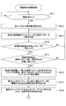
図11A及び図11Bは実施例2の制御部100Bが実行する制御処理の手順を説明するためのフローチャートである。制御部100Bは、メモリ102に格納された制御プログラムを読み込んで図11A及び図11Bの制御処理を実行する。
FIG. 11A and FIG. 11B are flowcharts for explaining a procedure of control processing executed by the control unit 100B of the second embodiment. The control unit 100B reads the control program stored in the memory 102 and executes the control processing of FIGS. 11A and 11B.
尚、図11A及び図11BのSB11、SB12およびSB14~SB17、SB24~SB29は、実質的に図7のSA11~SA16、SA19~SA24と同じ処理であるので、それらの説明は省略し、ここではSB13、SB18~SB23の処理について主に説明する。
11A and 11B, SB11, SB12, SB14 to SB17, and SB24 to SB29 are substantially the same as SA11 to SA16 and SA19 to SA24 in FIG. The processing of SB13 and SB18 to SB23 will be mainly described.
図11Aに示すSB13では、各指関節の動作に伴って発生する各物理量(トルク、回転角、応力)を検出したトルクセンサ94、角度センサ96、応力センサ130の検出信号の無線信号が受信されたか否かをチェックする。SB13において、トルクセンサ94、角度センサ96、応力センサ130の検出信号が受信されると、SB14に進む。
In SB13 shown in FIG. 11A, wireless signals of detection signals of the torque sensor 94, the angle sensor 96, and the stress sensor 130 that detect physical quantities (torque, rotation angle, stress) generated in accordance with the operation of each finger joint are received. Check whether or not. In SB13, when detection signals from the torque sensor 94, the angle sensor 96, and the stress sensor 130 are received, the process proceeds to SB14.
SB18では、トルクセンサ94、角度センサ96、応力センサ130により検出された物理量(実測値)とデータベース300に格納された各フェーズの基準パラメータと順次比較する。図10A、図10Bを参照して説明したように、全てのタスクおよび各タスク毎のフェーズは、マトリックス状に存在するので、物理量の実測値と各フェーズの基準パラメータとを、例えばA1、A2、A3・・・、B1、B2、B3・・・、C1、C2、C3・・・との順番で順次比較する。データベース300に格納された基準パラメータは、全てのタスク及びフェーズ(以下では、単に「タスク/フェーズ」という)の間で重複しないように設定されているので、全てのタスク及びフェーズの基準パラメータとの比較を行うと、物理量の実測値と一致する基準パラメータを有するタスク及びフェーズを抽出することができる。
In SB 18, physical quantities (actually measured values) detected by the torque sensor 94, the angle sensor 96, and the stress sensor 130 are sequentially compared with the reference parameters for each phase stored in the database 300. As described with reference to FIGS. 10A and 10B, all the tasks and phases for each task exist in a matrix, so that the actual measured values of the physical quantities and the reference parameters of each phase are represented by, for example, A1, A2, .., B1, B2, B3..., C1, C2, C3. The reference parameters stored in the database 300 are set so as not to overlap between all tasks and phases (hereinafter simply referred to as “task / phase”). When the comparison is performed, it is possible to extract a task and a phase having a reference parameter that matches the actual measured value of the physical quantity.
次のSB19では、トルクセンサ94、角度センサ96、応力センサ130により検出された物理量(実測値)とデータベース300に格納された各フェーズの基準パラメータとが一致したか否かをチェックしており、不一致の場合は上記SB18の処理に戻り、SB18、SB19の処理を繰り返す。また、SB19において、トルクセンサ94、角度センサ96、応力センサ130により検出された物理量(実測値)とデータベース300に格納された各フェーズの基準パラメータとが一致した場合は、SB20に進み、センサにより検出された物理量(実測値)とデータベース300に格納された各フェーズの基準パラメータとが一致した回数が予め設定された所定回数に達したか否かをチェックする。
In the next SB19, it is checked whether the physical quantity (actually measured value) detected by the torque sensor 94, the angle sensor 96, and the stress sensor 130 matches the reference parameter of each phase stored in the database 300. If they do not match, the process returns to SB18, and the processes of SB18 and SB19 are repeated. In SB19, when the physical quantity (measured value) detected by the torque sensor 94, the angle sensor 96, and the stress sensor 130 matches the reference parameter of each phase stored in the database 300, the process proceeds to SB20, where the sensor It is checked whether or not the number of times the detected physical quantity (actual value) matches the reference parameter of each phase stored in the database 300 has reached a predetermined number of times set in advance.
上記SB20において、一致した回数が予め設定された所定回数に達しない場合は、上記SB18の処理に戻り、SB18~SB20の処理を繰り返す。また、上記SB20において、一致した回数が予め設定された所定回数に達した場合は、図11BのSB21に進み、物理量の実測値に一致した基準パラメータに対応するタスク及びフェーズを選択し、装着者の動作を選択したタスク及びフェーズと推定する。
In SB20, when the number of times of coincidence does not reach the predetermined number set in advance, the process returns to the process of SB18 and the processes of SB18 to SB20 are repeated. If the number of matches in the SB 20 reaches a preset number, the process proceeds to SB 21 in FIG. 11B to select a task and phase corresponding to the reference parameter that matches the measured physical quantity, Is estimated as the selected task and phase.
次のSB22は、データベース300を参照することにより、補助すべき動作に対応するフェーズに割り付けたパワーアシスト率を選択し、当該パワーアシスト率となる動力を電動モータ44に発生させるように上記随意的制御信号を調整する(随意的制御手段)。
The next SB 22 selects the power assist rate assigned to the phase corresponding to the operation to be assisted by referring to the database 300, and the optional SB 22 causes the electric motor 44 to generate power corresponding to the power assist rate. Adjust the control signal (optional control means).
続いて、SB23に進み、調整後の随意的制御信号に応じた電流(総電流e)を生成し、当該総電流を電動モータ44に出力する。この後は、前述したSA19~SA24と同じ処理をSB24~SB29で行なう。
Subsequently, the process proceeds to SB 23, where a current (total current e) corresponding to the adjusted optional control signal is generated and the total current is output to the electric motor 44. Thereafter, the same processing as SA19 to SA24 described above is performed at SB24 to SB29.
このように、実施例2の制御処理によれば、トルクセンサ94、角度センサ96、応力センサ130から得られた物理量に基づいて装着者の動作及び関節20の動作を推定し、当該推定されたフェーズ毎に最適化されたパワーアシスト率となるように随意的制御信号を生成するため、電動モータ44が当該随意的制御信号に応じた動力付与を行うことにより、正常な人の指動作と同じように各指関節の動作がスムーズな動作となる。よって、装着者は、動作補助手袋20(図1乃至図3を参照)を装着した状態で各指の動作をスムーズに行なうことができる。
Thus, according to the control process of the second embodiment, the wearer's motion and the motion of the joint 20 are estimated based on the physical quantities obtained from the torque sensor 94, the angle sensor 96, and the stress sensor 130, and the estimated In order to generate an optional control signal so as to achieve a power assist rate optimized for each phase, the electric motor 44 applies power according to the optional control signal, and thus is the same as a normal human finger movement. Thus, the operation of each finger joint is a smooth operation. Therefore, the wearer can smoothly perform the operation of each finger while wearing the motion assisting gloves 20 (see FIGS. 1 to 3).
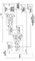
図12は実施例3の制御部100Cの制御系の信号処理を模式的に示すシステム系統図である。尚、図12において、前述した図5及び図8と同一部分には同一符号を付してその説明を省略する。
FIG. 12 is a system diagram schematically illustrating signal processing of the control system of the control unit 100C according to the third embodiment. In FIG. 12, the same parts as those in FIGS. 5 and 8 described above are denoted by the same reference numerals, and the description thereof is omitted.
図12に示す実施例3の制御部100Cは、生体電位処理手段200、随意的制御手段212、データベース300、自律的制御手段310、制御信号合成手段320、駆動電流生成手段220を有する。尚、動作補助手袋20は、前述した実施例1と同じ構成であるので、その説明を省略する。また、図12の制御部100Cは、図3の制御部100の一例である。
12 includes a biopotential processing unit 200, an optional control unit 212, a database 300, an autonomous control unit 310, a control signal synthesis unit 320, and a drive current generation unit 220. In addition, since the operation assistance glove 20 is the same structure as Example 1 mentioned above, the description is abbreviate | omitted. Further, the control unit 100C in FIG. 12 is an example of the control unit 100 in FIG.
制御部100Cの自律的制御手段310は、トルクセンサ94、角度センサ96、応力センサ130により検出されたセンサ信号f(物理情報信号)が受信されると、受信したトルクセンサ94、角度センサ96、応力センサ130の検出値(物理量)とデータベース300に格納された基準パラメータとを比較することにより、装着者のタスク及びフェーズを推定し、推定したフェーズに応じた駆動力を電動モータ44に発生させるための自律的制御信号d2を生成する。また、制御信号合成手段320は、随意的制御手段212からの随意的制御信号d1と自律的制御手段310からの自律的制御信号d2とを合成して制御信号dを生成する。
When the autonomous control means 310 of the control unit 100C receives the sensor signal f (physical information signal) detected by the torque sensor 94, the angle sensor 96, and the stress sensor 130, the received torque sensor 94, angle sensor 96, By comparing the detected value (physical quantity) of the stress sensor 130 with the reference parameter stored in the database 300, the task and phase of the wearer are estimated, and the electric motor 44 generates a driving force corresponding to the estimated phase. An autonomous control signal d2 is generated. In addition, the control signal combining unit 320 generates a control signal d by combining the optional control signal d1 from the optional control unit 212 and the autonomous control signal d2 from the autonomous control unit 310.
自律的制御手段310は、図9および図10A、図10Bに示すように、動作補助手袋20(図1乃至図3を参照)を装着した装着者が腕を動作する際、トルクセンサ94、角度センサ96、応力センサ130により検出されたトルク、回転角、応力の物理量が受信されると、受信したトルクセンサ94、角度センサ96、応力センサ130の検出信号とデータベース300に格納された各タスクの各フェーズの基準パラメータとを比較することにより、装着者のタスク及びフェーズを推定し、当該フェーズに応じた動力を電動モータ44に発生させるための自律的制御信号d2を生成する。
As shown in FIGS. 9, 10 </ b> A, and 10 </ b> B, the autonomous control unit 310 has a torque sensor 94, an angle when the wearer wearing the movement assisting glove 20 (see FIGS. 1 to 3) moves the arm. When the physical values of the torque, rotation angle, and stress detected by the sensor 96 and the stress sensor 130 are received, the detected signals of the received torque sensor 94, angle sensor 96, and stress sensor 130 and each task stored in the database 300 are received. By comparing the reference parameters of each phase, the task and phase of the wearer are estimated, and an autonomous control signal d2 for generating electric power corresponding to the phase in the electric motor 44 is generated.
制御信号合成手段320は、随意的制御手段212からの随意的制御信号d1と自律的制御手段310からの自律的制御信号d2とを合成する。自律的制御では、例えばフェーズ毎に一定の動力を付与する。従って、制御信号合成手段320で合成された制御信号dは、動作の開始から終了まで変化する随意的制御による動力と、フェーズ毎に一定の自律的制御による動力とを加算した動力とを電動モータ44に発生させるように形成されている。
The control signal synthesis unit 320 synthesizes the optional control signal d1 from the optional control unit 212 and the autonomous control signal d2 from the autonomous control unit 310. In autonomous control, for example, constant power is applied for each phase. Therefore, the control signal d synthesized by the control signal synthesizing means 320 is an electric motor that is obtained by adding the power by the optional control that changes from the start to the end of the operation and the power obtained by adding the power by the constant autonomous control for each phase. 44 is generated.
図13A及び図13Bは実施例3の制御部100Cが実行する制御処理を示すフローチャートである。制御部100Cは、メモリ102に格納された制御プログラムを読み込んで図13A及び図13Bの制御処理を実行する。
FIGS. 13A and 13B are flowcharts illustrating a control process executed by the control unit 100C according to the third embodiment. The control unit 100C reads the control program stored in the memory 102 and executes the control processes of FIGS. 13A and 13B.
尚、図13A及び図13BのSC11~SC13、SC15~SC17、SC22~SC27は、実質的に図7A及び図7BのSB11~SB13、SB18~SB20、SB24~SB29と同じ処理であるので、それらの説明は省略し、ここではSC14、SC18~SB21の処理について主に説明する。
13A and 13B are substantially the same processing as SB11 to SB13, SB18 to SB20, and SB24 to SB29 in FIGS. 7A and 7B. The description is omitted, and here, the processing of SC14, SC18 to SB21 will be mainly described.
図13Aに示すSC14では、生体電位センサ61~65により検出された生体電位信号aを用い、装着者の意思に従った駆動力を電動モータ44に発生させるための随意的制御信号d1を生成する(随意的制御手段)。尚、随意的制御信号d1は、前述した第1、2実施例と同様に、神経伝達信号に応じたパルス電流および筋電位信号に応じた駆動電流を生成するためのものとする。
13A, the bioelectric potential signal a detected by the bioelectric potential sensors 61 to 65 is used to generate an optional control signal d1 for causing the electric motor 44 to generate a driving force according to the wearer's intention. (Optional control means). The optional control signal d1 is used to generate a pulse current corresponding to the nerve transmission signal and a drive current corresponding to the myoelectric potential signal, as in the first and second embodiments.
SC18では、物理量の実測値に一致した基準パラメータに対応するタスク及びフェーズを選択し、装着者の指関節の動作を選択したタスク及びフェーズと推定すると共に、当該タスク及びフェーズに対応するハイブリッド比(随意的制御信号/自律的制御信号)を規定する。また、ハイブリッド比は、各タスク及びフェーズ毎に、装着者の動作を違和感なくアシストできるように予め設定され、データベース300に格納される。当該ハイブリッド比は、トルクセンサ94、角度センサ96、応力センサ130による実測の物理量とデータベース300に格納された基準パラメータとの比較によりフェーズが推定されると、上述したように制御部100Cによって自動的に規定される。
In SC18, the task and phase corresponding to the reference parameter that matches the actual measured value of the physical quantity are selected, the wearer's finger joint motion is estimated as the selected task and phase, and the hybrid ratio ( Voluntary control signal / autonomous control signal). Further, the hybrid ratio is set in advance so as to assist the wearer's operation without a sense of incongruity for each task and phase, and is stored in the database 300. The hybrid ratio is automatically calculated by the control unit 100C as described above when the phase is estimated by comparing the physical quantity actually measured by the torque sensor 94, the angle sensor 96, and the stress sensor 130 with the reference parameter stored in the database 300. Stipulated in
続いて、SC19に進み、推定したフェーズに応じた駆動力を電動モータ44に発生させるための自律的制御信号を生成する(自律的制御手段)。
Subsequently, the process proceeds to SC19 to generate an autonomous control signal for causing the electric motor 44 to generate a driving force corresponding to the estimated phase (autonomous control means).
次の図13BのSC20では、規定したハイブリッド比となるように随意的制御信号d1および自律的制御信号d2を合成して総制御信号dを生成する(制御信号合成手段)。
In the next SC20 in FIG. 13B, the total control signal d is generated by synthesizing the optional control signal d1 and the autonomous control signal d2 so that the specified hybrid ratio is obtained (control signal synthesizing means).
さらに、SC21に進み、当該総制御信号dに応じて生成した駆動電流eに対応する指令信号を出力する。総制御信号dは、随意的制御信号/自律的制御信号の割合から得られる所要のハイブリッド比となるように生成される。そのため、動作補助手袋20の電動モータ44は、総制御信号に応じた駆動電流eを供給されることにより、随意的制御信号及び自律的制御信号に応じた駆動力を発生することができ、各指関節の動作が正常な腕の動作と同じようにスムーズな動作となる。よって、装着者は、動作補助手袋20(図1乃至図3を参照)を装着した状態でスムーズな動作を行うことができる。
Further, the process proceeds to SC21, and a command signal corresponding to the drive current e generated according to the total control signal d is output. The total control signal d is generated to have a required hybrid ratio obtained from the ratio of the voluntary control signal / autonomous control signal. Therefore, the electric motor 44 of the motion assisting glove 20 can generate the driving force according to the optional control signal and the autonomous control signal by being supplied with the driving current e according to the total control signal, The movement of the finger joint is as smooth as the normal arm movement. Therefore, the wearer can perform a smooth operation while wearing the operation assisting gloves 20 (see FIGS. 1 to 3).
図14は実施例4の制御部100Dの制御系の信号処理を模式的に示すシステム系統図である。尚、図14において、前述した図5及び図8及び図12と同一部分には同一符号を付してその説明を省略する。
FIG. 14 is a system diagram schematically showing the signal processing of the control system of the control unit 100D according to the fourth embodiment. In FIG. 14, the same parts as those in FIGS. 5, 8 and 12 described above are denoted by the same reference numerals, and the description thereof is omitted.
図14に示す実施例4の制御部100Dは、生体電位処理手段200、随意的制御手段212、データベース300、自律的制御手段310、制御信号合成手段320、駆動電流生成手段220を有する。尚、動作補助手袋20は、前述した実施例1と同じ構成であるので、その説明を省略する。また、図14の制御部100Dは、図3の制御部100の一例である。
14 includes a biopotential processing means 200, an optional control means 212, a database 300, an autonomous control means 310, a control signal synthesizing means 320, and a drive current generating means 220. In addition, since the operation assistance glove 20 is the same structure as Example 1 mentioned above, the description is abbreviate | omitted. Further, the control unit 100D of FIG. 14 is an example of the control unit 100 of FIG.
制御部100Dの随意的制御手段212および自律的制御手段310は、トルクセンサ94、角度センサ96、応力センサ130の検出値(物理量)とデータベース300に格納された基準パラメータとを比較することにより、装着者が行おうとしている指関節動作のタスク及びフェーズを推定し、推定された当該フェーズに応じたハイブリッド比およびパワーアシスト率となるように、随意的制御信号d1および自律的制御信号d2を生成する機能を有する。
The optional control unit 212 and the autonomous control unit 310 of the control unit 100D compare the detection values (physical quantities) of the torque sensor 94, the angle sensor 96, and the stress sensor 130 with the reference parameters stored in the database 300, Estimate the task and phase of the finger joint movement that the wearer is going to perform, and generate the voluntary control signal d1 and the autonomous control signal d2 so that the hybrid ratio and power assist rate corresponding to the estimated phase are obtained It has the function to do.
従って、随意的制御手段212は、神経伝達信号および筋電位信号に基づいて動作補助手袋20(図1乃至図3を参照)の電動モータ44の駆動を制御する制御信号と、トルクセンサ94、角度センサ96、応力センサ130により検出された装着者の動作に関する物理量からデータベース300からタスク及びフェーズを推定し、推定したフェーズに対応するパワーアシスト率となるように駆動力を電動モータ44に発生させる制御信号とを生成する。
Therefore, the optional control means 212 includes a control signal for controlling the driving of the electric motor 44 of the auxiliary assisting glove 20 (see FIGS. 1 to 3), a torque sensor 94, an angle based on the nerve transmission signal and the myoelectric potential signal. Control in which tasks and phases are estimated from the database 300 based on physical quantities related to the wearer's motion detected by the sensor 96 and the stress sensor 130, and a driving force is generated in the electric motor 44 so as to achieve a power assist rate corresponding to the estimated phase. Signal.
図15A及び図15Bは実施例4の制御部100Dが実行する制御処理の手順を説明するためのフローチャートである。制御部100Dは、メモリ102に格納された制御プログラムを読み込んで図15A及び図15Bの制御処理を実行する。
15A and 15B are flowcharts for explaining the procedure of the control process executed by the control unit 100D of the fourth embodiment. The control unit 100D reads the control program stored in the memory 102 and executes the control processing of FIGS. 15A and 15B.
尚、図15A及び図15BのSD11~SD17、SD21~SD27は、実質的に図13A及び図13BのSC11~SC17、SC21~SC27と同じ処理であるので、それらの説明は省略し、ここではSD18~SD20の処理について主に説明する。
Note that SD11 to SD17 and SD21 to SD27 in FIGS. 15A and 15B are substantially the same as SC11 to SC17 and SC21 to SC27 in FIGS. 13A and 13B. The processing of SD20 will be mainly described.
図15Aに示すSD18では、物理量の実測値に一致した基準パラメータに対応するタスク及びフェーズを選択し、装着者の動作を選択したタスク及びフェーズと推定すると共に、推定された当該タスク及びフェーズに対応するハイブリッド比(随意的制御信号/自律的制御信号)を規定する。さらに、データベース300を参照することにより、補助すべき動作に対応するフェーズに割り付けたパワーアシスト率を規定する。
In SD18 shown in FIG. 15A, the task and phase corresponding to the reference parameter that matches the actual measurement value of the physical quantity are selected, and the wearer's motion is estimated as the selected task and phase, and the estimated task and phase are supported. A hybrid ratio (optional control signal / autonomous control signal) is defined. Further, by referring to the database 300, the power assist rate assigned to the phase corresponding to the operation to be assisted is defined.
次のSD19では、推定したフェーズに応じた動力で電動モータ44を駆動するための自律的制御信号を生成する。
In the next SD19, an autonomous control signal for driving the electric motor 44 with power according to the estimated phase is generated.
続いて、図15BのSD20に進み、上記のように規定されたハイブリッド比およびパワーアシスト率となるように随意的制御信号d1および自律的制御信号d2を合成して総制御信号dを生成する。これにより、SC21では、規定されたハイブリッド比およびパワーアシスト率となるように随意的制御信号d1および自律的制御信号d2を合成した総制御信号dに応じて生成した駆動電流eに対応する指令信号を生成する。
Subsequently, the process proceeds to SD20 in FIG. 15B, and the total control signal d is generated by synthesizing the optional control signal d1 and the autonomous control signal d2 so as to achieve the hybrid ratio and the power assist rate defined as described above. Thereby, in SC21, the command signal corresponding to the drive current e generated according to the total control signal d obtained by synthesizing the optional control signal d1 and the autonomous control signal d2 so that the specified hybrid ratio and power assist rate are obtained. Is generated.
そのため、動作補助手袋20(図1乃至図3を参照)の電動モータ44は、上記のように規定されたハイブリッド比およびパワーアシスト率となるように総制御信号に応じた駆動電流eを供給されることにより、随意的制御信号及び自律的制御信号に応じた駆動力を発生することができ、各指関節の動作が正常な腕の動作と同じようにスムーズな動作となる。よって、装着者は、動作補助手袋20(図1乃至図3を参照)を装着した状態で各指関節をスムーズに動作させることができる。
Therefore, the electric motor 44 of the motion assisting glove 20 (see FIGS. 1 to 3) is supplied with a drive current e corresponding to the total control signal so that the hybrid ratio and the power assist rate specified as described above are obtained. As a result, it is possible to generate a driving force according to the voluntary control signal and the autonomous control signal, and the operation of each finger joint is as smooth as the normal arm operation. Therefore, the wearer can smoothly operate each of the finger joints while wearing the operation assisting gloves 20 (see FIGS. 1 to 3).
図16は実施例5の制御部100Eの制御系の信号処理を模式的に示すシステム系統図である。尚、図16において、前述した図5、図8、図12、図14と同一部分には同一符号を付してその説明を省略する。
FIG. 16 is a system diagram schematically showing the signal processing of the control system of the control unit 100E of the fifth embodiment. In FIG. 16, the same parts as those in FIGS. 5, 8, 12, and 14 described above are denoted by the same reference numerals, and the description thereof is omitted.
図16に示す実施例5では、装着者の手首から生体電位信号aが得られない場合の制御システムであり、生体電位センサ61~65を用いない制御方法で動作補助手袋20(図1乃至、図3を参照)の電動モータ44の駆動力を制御する。尚、動作補助手袋20は、前述した実施例1と同じ構成であるので、その説明を省略する。また、図16の制御部100Eは、図3の制御部100の一例である。
Example 5 shown in FIG. 16 is a control system when the bioelectric potential signal a cannot be obtained from the wrist of the wearer, and the operation assisting glove 20 (FIGS. 1 to The driving force of the electric motor 44 shown in FIG. 3 is controlled. In addition, since the operation assistance glove 20 is the same structure as Example 1 mentioned above, the description is abbreviate | omitted. Further, the control unit 100E in FIG. 16 is an example of the control unit 100 in FIG.
実施例5の制御部100Eは、データベース300、自律的制御手段310、駆動電流生成手段220を有する。制御部100Eは、装着者から生体電位信号aが得られないため、随意的制御手段212が設けられてなく、自律的制御手段310によって生成される自律制御信号d2が駆動電流生成手段220に供給される。
The control unit 100E according to the fifth embodiment includes a database 300, an autonomous control unit 310, and a drive current generation unit 220. Since the biopotential signal a cannot be obtained from the wearer, the control unit 100E is not provided with the optional control means 212, and the autonomous control signal d2 generated by the autonomous control means 310 is supplied to the drive current generation means 220. Is done.
自律的制御手段310は、トルクセンサ94、角度センサ96、応力センサ130の検出値(物理量)とデータベース300に格納された基準パラメータとを比較することにより、装着者が行おうとしている各指関節のタスク及びフェーズを推定し、推定された当該フェーズに応じたハイブリッド比およびパワーアシスト率となるように、自律的制御信号d2を生成する。そのため、駆動電流生成手段220は、自律的制御信号d2に応じた電流を生成し、電動モータ44に供給する。
The autonomous control means 310 compares the detected values (physical quantities) of the torque sensor 94, the angle sensor 96, and the stress sensor 130 with the reference parameters stored in the database 300, so that each finger joint that the wearer is going to perform is compared. The autonomous control signal d2 is generated so that the hybrid ratio and the power assist rate corresponding to the estimated phase are obtained. Therefore, the drive current generator 220 generates a current corresponding to the autonomous control signal d <b> 2 and supplies it to the electric motor 44.
図17A及び図17Bは実施例5の制御部100Eが実行する制御処理の手順を説明するためのフローチャートである。制御部100Eは、メモリ102に格納された制御プログラムを読み込んで図17の制御処理を実行する。
FIGS. 17A and 17B are flowcharts for explaining a procedure of control processing executed by the control unit 100E according to the fifth embodiment. The control unit 100E reads the control program stored in the memory 102 and executes the control process of FIG.
尚、図17A及び図17BのSE11~SE25は、実質的に図15A及び図15BのSD12、SD14を除いた処理手順であり、SD11、SD12、SD13~SD17、AD19~SD27と同じ処理であるので、それらの説明は省略する。ここでは、SE18の処理について説明する。
Note that SE11 to SE25 in FIGS. 17A and 17B are processing procedures that substantially exclude SD12 and SD14 in FIGS. 15A and 15B, and are the same processing as SD11, SD12, SD13 to SD17, and AD19 to SD27. These descriptions are omitted. Here, the processing of SE18 will be described.
SE18では、規定されたハイブリッド比およびパワーアシスト率となるように自律的制御信号d2を生成する。これにより、規定されたハイブリッド比及びパワーアシスト率となる動力を電動モータ44に発生させることが可能になる。
In SE18, the autonomous control signal d2 is generated so that the specified hybrid ratio and power assist rate are obtained. As a result, it becomes possible to cause the electric motor 44 to generate power having a specified hybrid ratio and power assist rate.
このように、実施例5の制御部100Eは、装着者の手首から生体電位信号aが得られない場合には、自律的制御手段310によって生成される自律制御信号d2に応じて動作補助手袋20の電動モータ44から駆動力が得られるので、各指関節の動作がスムーズな動作となる。よって、装着者は、動作補助手袋20(図1乃至図3を参照)を装着した状態で各指関節をスムーズに動作させることができる。
As described above, when the bioelectric potential signal a cannot be obtained from the wearer's wrist, the control unit 100E according to the fifth embodiment performs the operation assisting glove 20 according to the autonomous control signal d2 generated by the autonomous control unit 310. Since the driving force can be obtained from the electric motor 44, the operation of each finger joint is a smooth operation. Therefore, the wearer can smoothly operate each of the finger joints while wearing the operation assisting gloves 20 (see FIGS. 1 to 3).
図18は実施例6の制御部100Fの制御系の信号処理を模式的に示すシステム系統図である。尚、図18において、前述した図5、図8、図12、図14、図16と同一部分には同一符号を付してその説明を省略する。
FIG. 18 is a system diagram schematically illustrating signal processing of the control system of the control unit 100F according to the sixth embodiment. In FIG. 18, the same parts as those in FIGS. 5, 8, 12, 14, and 16 described above are denoted by the same reference numerals, and the description thereof is omitted.
制御部100Fは、前述した駆動電流生成手段220、感覚フィードバック信号生成手段230の他に、キャリブレーションデータベース400、フェーズ特定手段410、差分導出手段420、パラメータ補正手段430、キャリブレーション制御手段440、負荷発生手段450を有する。尚、動作補助手袋20は、前述した実施例1と同じ構成であるので、その説明を省略する。また、図18の制御部100Fは、図3の制御部100の一例である。
In addition to the drive current generation unit 220 and the sensory feedback signal generation unit 230 described above, the control unit 100F includes a calibration database 400, a phase identification unit 410, a difference derivation unit 420, a parameter correction unit 430, a calibration control unit 440, a load It has the generating means 450. In addition, since the operation assistance glove 20 is the same structure as Example 1 mentioned above, the description is abbreviate | omitted. Further, the control unit 100F in FIG. 18 is an example of the control unit 100 in FIG.
キャリブレーションデータベース400は、装着者が発生する筋力に対する筋電位(生体電位)の検出感度に応じて制御信号のパラメータを補正するためのデータ記憶手段である。
The calibration database 400 is data storage means for correcting the parameter of the control signal in accordance with the detection sensitivity of the myoelectric potential (bioelectric potential) with respect to the muscle force generated by the wearer.
すなわち、キャリブレーションデータベース400は、動作補助手袋20(図1乃至図3を参照)を手に装着した装着者が発する筋力および筋電位信号(生体電位信号)の第1の対応関係を予め格納した第1記憶領域と、装着者が各指関節の基本動作を行う過程で関節角度の変化とともに発する筋力および筋電位信号(生体電位信号)の第2の対応関係を予め格納した第2記憶領域とを有する。
That is, the calibration database 400 stores in advance the first correspondence relationship between the muscular strength and the myoelectric potential signal (bioelectric potential signal) generated by the wearer wearing the operation assisting glove 20 (see FIGS. 1 to 3). A first storage area, and a second storage area that stores in advance a second correspondence relationship between a muscle force and a myoelectric potential signal (bioelectric potential signal) that are generated along with a change in joint angle in the course of the wearer performing a basic motion of each finger joint; Have
各物理量センサによって検出された関節角度及び生体電位センサ61~65によって検出された筋電位信号は、キャリブレーションデータベース400に入力される。
The joint angle detected by each physical quantity sensor and the myoelectric potential signals detected by the bioelectric potential sensors 61 to 65 are input to the calibration database 400.
そして、キャリブレーション制御手段440は、動作補助手袋20が装着者の関節20に装着された後、装着者による各指関節の基本動作において発生する生体信号と第2の対応関係とに基づいて、第1の対応関係を満たすように生体電位信号に応じた電動モータ44(図1乃至図3を参照)による補助動力の補正を行う。
Then, the calibration control means 440, after the motion assisting glove 20 is attached to the joint 20 of the wearer, based on the biological signal generated in the basic motion of each finger joint by the wearer and the second correspondence relationship, The auxiliary power is corrected by the electric motor 44 (see FIGS. 1 to 3) corresponding to the bioelectric potential signal so as to satisfy the first correspondence relationship.
すなわち、キャリブレーション制御手段440は、装着者が動作補助手袋20が装着されて電源スイッチがオンに操作されたときに、キャリブレーション制御処理を実行して負荷発生手段450により駆動電流生成手段220に対して電動モータ44からの駆動力を負荷(入力トルク)として装着者の各指関節に段階的に付与させ、駆動力と拮抗するように装着者は各指関節の筋力を発生させる。
That is, the calibration control unit 440 executes the calibration control process when the wearer wears the operation assisting glove 20 and the power switch is turned on, and the load generation unit 450 causes the drive current generation unit 220 to perform calibration control processing. On the other hand, the driving force from the electric motor 44 is applied stepwise to each finger joint of the wearer as a load (input torque), and the wearer generates muscle strength of each finger joint so as to antagonize the driving force.
その後、電動モータ44からの駆動力を付与された各指関節は、予め決められた所定のキャリブレーション動作(例えば、タスクA:指を伸ばす)を行って筋力を発生させる。これにより、上記キャリブレーション動作に伴って角度センサ96(図1参照)が関節角度を検出すると共に、生体電位センサ61~65が手首の筋電位信号を検出する。
Thereafter, each finger joint to which the driving force from the electric motor 44 is applied performs a predetermined calibration operation (for example, task A: extend the finger) to generate muscle strength. Thereby, along with the calibration operation, the angle sensor 96 (see FIG. 1) detects the joint angle, and the biopotential sensors 61 to 65 detect the myoelectric potential signal of the wrist.
そして、フェーズ特定手段410では、角度センサ96により検出した関節角度をキャリブレーションデータベース400に格納された関節角度と比較することにより、装着者のキャリブレーション動作パターンのフェーズを特定する。
The phase specifying means 410 specifies the phase of the wearer's calibration operation pattern by comparing the joint angle detected by the angle sensor 96 with the joint angle stored in the calibration database 400.
また、差分導出手段420では、キャリブレーション制御処理の開始により、負荷発生手段450により付与された電動モータ44の負荷(入力トルク)と、生体電位センサ61~65により検出された上腕の筋電位信号(実測値)に対応する筋力(推定トルク)とを比較し、両者の差分を求め上記第2の対応関係を求める。
In addition, the difference deriving unit 420 starts the calibration control process, and the load (input torque) of the electric motor 44 applied by the load generating unit 450 and the myoelectric potential signal of the upper arm detected by the bioelectric potential sensors 61 to 65. The muscle strength (estimated torque) corresponding to (actually measured value) is compared, the difference between the two is obtained, and the second correspondence relationship is obtained.
また、パラメータ補正手段430では、フェーズ特定手段410によって特定されたフェーズにおける差分導出手段420によって算出された負荷(入力トルク)と筋力(推定トルク)との差に基づいて、上記第1の対応関係を満足するようにパラメータKを補正する。負荷発生手段450により付与された電動モータ44からの入力トルクと、生体電位センサ61~65により検出された筋電位信号(実測値)に対応する筋力との差がないときは、基準パラメータを補正しない。
In the parameter correction unit 430, the first correspondence relationship is based on the difference between the load (input torque) and the muscle strength (estimated torque) calculated by the difference deriving unit 420 in the phase specified by the phase specifying unit 410. The parameter K is corrected so as to satisfy When there is no difference between the input torque from the electric motor 44 applied by the load generating means 450 and the muscle force corresponding to the myoelectric potential signals (actual measurement values) detected by the bioelectric potential sensors 61 to 65, the reference parameter is corrected. do not do.
しかし、負荷発生手段450により付与された電動モータ44からの入力トルクと、生体電位センサ61~65により検出された筋電位信号(実測値)に対応する筋力との差があるときは、両者が一致するようにパラメータKを補正する。その際、補正パラメータK’は、入力トルクと推定トルクとが等しくなるように設定される。
However, when there is a difference between the input torque from the electric motor 44 applied by the load generating means 450 and the muscle force corresponding to the myoelectric potential signals (actual measurement values) detected by the bioelectric potential sensors 61 to 65, The parameter K is corrected so as to match. At this time, the correction parameter K ′ is set so that the input torque and the estimated torque are equal.
そして、キャリブレーション制御手段440は、パラメータ補正手段430によって補正されたパラメータを当該装着者のパラメータとして設定し、次のフェーズに対するキャリブレーションを行う。
Then, the calibration control means 440 sets the parameter corrected by the parameter correction means 430 as the parameter of the wearer, and performs calibration for the next phase.
このように、キャリブレーションによって設定されたパラメータを用いて生体電位センサ61~65によって検出された生体電位信号に応じたアシスト力を発生するように電動モータ44を制御するため、装着者のその日の状態(皮膚の抵抗値や生体電位の状態など)や生体電位センサ61~65の取付位置のずれなどに拘り無くパワーアシスト率が所定値を保つように制御することが可能になる。
In this way, the electric motor 44 is controlled so as to generate the assist force according to the biopotential signal detected by the biopotential sensors 61 to 65 using the parameters set by the calibration. Regardless of the state (skin resistance value, biopotential state, etc.) or the displacement of the attachment positions of the biopotential sensors 61 to 65, it is possible to control the power assist rate to maintain a predetermined value.
また、制御部100Fには、角度センサ96によって検出された関節角度及び生体電位センサ61~65によって検出された筋電位信号が供給されており、関節角度及び筋電位信号に応じた各フェーズ毎の電動モータ44からの駆動力をキャリブレーション制御手段440によって設定された補正パラメータK’を用いて演算し、その演算結果から得られた制御信号を駆動電流生成手段220に供給する。
Further, the joint angle detected by the angle sensor 96 and the myoelectric potential signals detected by the bioelectric potential sensors 61 to 65 are supplied to the control unit 100F, and each phase corresponding to the joint angle and the myoelectric potential signal is supplied. The driving force from the electric motor 44 is calculated using the correction parameter K ′ set by the calibration control unit 440, and a control signal obtained from the calculation result is supplied to the driving current generation unit 220.
また、キャリブレーション制御手段440は、リモートコントローラ40の電源スイッチ150がオンに操作される度にキャリブレーション制御処理を実行するようにしても良いし、あるいは、専用のキャリブレーションスイッチ460を設けることで、操作者が自らの操作でキャリブレーション制御処理を実行するようにしても良い。また、タイマスイッチ470を設けることで、予め設定された任意の時間(例えば、毎朝8時、あるいは月曜の8時といった具合)になるとキャリブレーション制御処理を自動的に実行することも可能である。
The calibration control means 440 may execute the calibration control process every time the power switch 150 of the remote controller 40 is turned on, or by providing a dedicated calibration switch 460. The operator may execute the calibration control process by his / her own operation. In addition, by providing the timer switch 470, it is possible to automatically execute the calibration control process at an arbitrary time set in advance (for example, every morning at 8:00 or Monday at 8:00).
キャリブレーション制御処理は、装着者が動作補助手袋20の動作を練習する過程で動力補正を行なうために頻繁に実行されることが望ましいが、練習開始から1週間以上経過した場合には、任意の時間毎に実行するように切替えることができる。そのため、電源スイッチ150やキャリブレーションスイッチ460やタイマスイッチ470を使用回数(練習回数)に応じて使い分けるようにしても良いし、あるいはキャリブレーションスイッチ460またはタイマスイッチ470を適宜操作するようにしても良い。
It is desirable that the calibration control process is frequently executed in order to perform power correction in the process of the wearer practicing the operation of the motion assisting gloves 20, but if one week or more has elapsed since the start of practice, It can be switched to run every hour. Therefore, the power switch 150, the calibration switch 460, and the timer switch 470 may be properly used according to the number of times of use (the number of exercises), or the calibration switch 460 or the timer switch 470 may be appropriately operated. .
ここで、実施例6の制御部100Fが実行する制御処理の手順について図19に示すフローチャートを参照して説明する。
Here, the procedure of the control process executed by the control unit 100F of the sixth embodiment will be described with reference to the flowchart shown in FIG.
図19に示されるように、制御部100Fは、S111で動作補助手袋20(図1乃至図3を参照)が装着者の手に装着された後に電源スイッチがオンに操作されると、S112に進み、電源オン操作が初回かどうかをチェックする。S112において、初回である場合には、S113に進み、初期設定モードに移行し、S114で初期設定キャリブレーション処理(キャリブレーション手段)を実行する。
As shown in FIG. 19, when the power switch is turned on after the operation assisting glove 20 (see FIGS. 1 to 3) is attached to the wearer's hand in S <b> 111, the control unit 100 </ b> F proceeds to S <b> 112. Go ahead and check if the power on operation is the first time. In S112, if it is the first time, the process proceeds to S113 to shift to an initial setting mode, and an initial setting calibration process (calibration means) is executed in S114.
すなわち、S114では、動作補助手袋20の電動モータ44から付与された負荷としての駆動力に対する生体電位センサ61~65によって検出された生体電位を受信し、当該生体電位信号に基づいて補正値を求める。S115において、電動モータ44への印加電圧を1ランク上げて負荷を増大させる。続いて、S116に進み、負荷が予め設定された上限値に達したかどうかを確認する。S116において、負荷が予め設定された上限値でないときは、上記S114に戻り、S114~S116の処理を繰り返す。
That is, in S114, the bioelectric potential detected by the biopotential sensors 61 to 65 with respect to the driving force as the load applied from the electric motor 44 of the motion assisting glove 20 is received, and the correction value is obtained based on the biopotential signal. . In S115, the voltage applied to the electric motor 44 is increased by one rank to increase the load. Then, it progresses to S116 and it is confirmed whether the load has reached the preset upper limit value. In S116, when the load is not the preset upper limit value, the process returns to S114, and the processes of S114 to S116 are repeated.
そして、S116において、負荷が予め設定された上限値に達したときは、S117に進み、上記キャリブレーションで得られたパラメータK’を設定する。
In S116, when the load reaches the preset upper limit value, the process proceeds to S117, and the parameter K ′ obtained by the calibration is set.
次のS117では、動作補助手袋20を装着された装着者が静止状態でのキャリブレーションによって得られた装着者の筋力に応じた補正値(パラメータK’)を設定する(補正値設定手段)。すなわち、S115では、例えば、装着者が各指関節を伸ばした状態で静止したまま1Nmの力を出したときの表面筋電位の値が1になるようにパラメータKを求める。初回のキャリブレーションでは、電動モータ44の駆動力(トルクτm)を負荷(入力トルク)として装着者の各指関節に段階的に付与させるのに対して、装着者は駆動力と拮抗するように各指関節に筋力を発生させる。
In the next S117, the wearer wearing the motion assisting gloves 20 sets a correction value (parameter K ') corresponding to the wearer's muscular strength obtained by the calibration in the stationary state (correction value setting means). That is, in S115, for example, the parameter K is obtained so that the value of the surface myoelectric potential becomes 1 when the wearer gives a force of 1 Nm while standing still with each finger joint extended. In the initial calibration, the driving force (torque τm) of the electric motor 44 is applied stepwise to each finger joint of the wearer as a load (input torque), whereas the wearer antagonizes the driving force. Generate muscle strength at each finger joint.
このように、電動モータ44から付与された駆動力に抗して発生した生体電位信号を生体電位センサ61~65によって検出し、当該検出信号に基づいて演算処理のパラメータを生成し、当該パラメータを当該装着者固有の補正値としてキャリブレーションデータベース400に格納する。
In this way, the biopotential signals generated against the driving force applied from the electric motor 44 are detected by the biopotential sensors 61 to 65, and parameters for the arithmetic processing are generated based on the detection signals. The correction value unique to the wearer is stored in the calibration database 400.
これにより、動作補助手袋20が装着者に装着された直後に、装着者が所定の基本動作(キャリブレーション動作)を行う過程で発する動力および生体電位信号の対応関係とに基づいて、装着者が発する動力および生体電位信号の対応関係を満たすように生体信号に応じた電動モータ44の駆動力の補正を行うことが可能になる。
As a result, immediately after the movement assisting glove 20 is worn on the wearer, the wearer is able to perform the operation based on the correspondence between the power and the bioelectric potential signal generated in the process in which the wearer performs a predetermined basic operation (calibration operation). It becomes possible to correct the driving force of the electric motor 44 in accordance with the biological signal so as to satisfy the correspondence relationship between the generated power and the biological potential signal.
その後は、S118に進み、通常の制御処理を実行する制御モードに移行する。そして、S119において、電源スイッチがオフに操作されるまで、通常の制御モードが継続される。
Thereafter, the process proceeds to S118 and shifts to a control mode in which normal control processing is executed. In S119, the normal control mode is continued until the power switch is turned off.
また、上記S112において、電源オン操作が2回目以降である場合には、S120に進み、前述した再設定モードに移行する。そして、S121では、装着者がワンモーション(1回の動作)での補正値設定キャリブレーション(キャリブレーション手段)を実行し、所定のキャリブレーション動作(例えば、指を伸ばした状態から指を曲げて手を握る動作パターン)を行うのに伴って得られた装着者の筋力に応じた補正値(パラメータK’)を設定する(補正値設定手段)。その後は、上記S117~S119の処理を実行する。
In S112, when the power-on operation is performed for the second time or later, the process proceeds to S120 and shifts to the above-described reset mode. In S121, the wearer executes a correction value setting calibration (calibration means) in one motion (one operation), and bends the finger from a predetermined calibration operation (for example, the finger is stretched). A correction value (parameter K ′) is set according to the wearer's muscular strength obtained by performing the movement pattern of grasping the hand (correction value setting means). Thereafter, the processes of S117 to S119 are executed.
尚、本実施例では、2回目以降ワンモーションによるキャリブレーションを行うものとしたが、これに限らず、2回目以降も初回と同様に静止状態のまま補正値設定キャリブレーションを行うようにしても良い。
In this embodiment, the one-motion calibration is performed after the second time. However, the present invention is not limited to this, and the correction value setting calibration may be performed in the still state in the second and subsequent times as in the first time. good.
次に、各補正値設定モード毎の制御処理について図20乃至図22を参照して説明する。
図20は初期設定を行う初回キャリブレーションの制御手順を示すフローチャートである。尚、初回キャリブレーションの場合、前述したように、装着者がモータ負荷に対して関節20の静止状態を保つように筋力を発生させることにより補正値を設定する。
Next, control processing for each correction value setting mode will be described with reference to FIGS.
FIG. 20 is a flowchart showing a control procedure of initial calibration for performing initial setting. In the case of the initial calibration, as described above, the correction value is set by generating a muscle force so that the wearer keeps the joint 20 stationary with respect to the motor load.
図20に示されるように、制御部100Fは、S131において、装着者が各指関節を静止状態に保った状態で電動モータ44に所定駆動電流を供給して駆動力(入力トルク)を負荷として付与する。そのため、装着者は、例えば、各指関節を伸ばした状態のまま電動モータ44の駆動力に拮抗するように筋力を発生させることになる。
As shown in FIG. 20, the control unit 100F supplies a predetermined driving current to the electric motor 44 with the driving force (input torque) as a load in step S131 while the wearer keeps each finger joint stationary. Give. Therefore, for example, the wearer generates muscular power so as to antagonize the driving force of the electric motor 44 with each finger joint extended.
次のS132では、生体電位センサ61~65によって検出された装着者の手首の筋電位信号(生体電位信号)を取得する。次のS133では、実測された筋電位信号に基づいて仮想トルクを演算により推定する。
In the next S132, the myoelectric potential signal (bioelectric potential signal) of the wearer's wrist detected by the bioelectric potential sensors 61 to 65 is acquired. In the next S133, a virtual torque is estimated by calculation based on the actually measured myoelectric potential signal.
その後、S134に進み、負荷として付与された入力トルクと上記仮想トルクとを比較する。そして、S135において、入力トルクと仮想トルクとの比率を求める。次のS136では、キャリブレーションデータベース400に格納された各フェーズ毎の負荷に対するパラメータを読み出し、当該パラメータに上記比率をかけて駆動電流生成手段220に供給される制御信号の補正値(補正パラメータ)を求める。続いて、S137に進み、補正パラメータを自律的制御のパラメータとして設定する(補正値設定手段)。
Thereafter, the process proceeds to S134, and the input torque applied as a load is compared with the virtual torque. In S135, the ratio between the input torque and the virtual torque is obtained. In the next S136, the parameter for the load for each phase stored in the calibration database 400 is read out, and the correction value (correction parameter) of the control signal supplied to the drive current generation means 220 is multiplied by the above ratio. Ask. Subsequently, the process proceeds to S137, and the correction parameter is set as a parameter for autonomous control (correction value setting means).
このように、関節20に動作補助手袋20が装着された装着者は、静止した状態のままその日の状態に応じた生体信号のキャリブレーションを自動的に行うことができる。そのため、キャリブレーションに要する労力と時間を大幅に削減することが可能になる。
Thus, the wearer with the motion assisting glove 20 attached to the joint 20 can automatically calibrate the biological signal according to the state of the day while still. Therefore, the labor and time required for calibration can be greatly reduced.
さらに、筋力が衰えた装着者に対してキャリブレーションを行うために余計な負担を強いることがなく、当該装着者の状態に応じた補正値を設定し、装着者の筋電位信号に基づく駆動力を装着者の動作に連動して正確に付与することが可能になる。
Furthermore, it does not impose an extra burden on the wearer who has weakened muscle strength, and a correction value is set according to the wearer's condition, and the driving force based on the wearer's myoelectric potential signal. Can be accurately given in conjunction with the movement of the wearer.
よって、キャリブレーションを行う際に装着者の意思に沿ったアシスト力が電動モータ44から付与され、アシスト力が過大になったり、過小になったりせず、装着者の動作を安定的にアシストして動作補助手袋20の信頼性をより高めることができる。
Therefore, when the calibration is performed, an assist force in accordance with the intention of the wearer is applied from the electric motor 44, and the assist force is not excessively increased or decreased, and the operation of the wearer is stably assisted. Thus, the reliability of the motion assisting glove 20 can be further increased.
特に装着者が初心者の場合のように、装着された動作補助手袋20を思うように使うことが難しいと思われる状況においても、装着者は安心してキャリブレーションを行うことができる。
Especially when the wearer is a beginner, it is possible for the wearer to calibrate with peace of mind even in a situation where it is difficult to use the worn motion assisting glove 20 as expected.
次に前述した再設定モード1(図19のS120参照)のキャリブレーション制御処理について図21を参照して説明する。
Next, the calibration control process in the above-described reset mode 1 (see S120 in FIG. 19) will be described with reference to FIG.
図21はワンモーション(1回の動作)による再設定キャリブレーションの制御手順を示すフローチャートである。尚、ワンモーションによるキャリブレーションを行う場合、装着者は、指を伸ばした状態から指を曲げた状態に1回だけ動かすことになる。また、メモリ102には、キャリブレーションの動作に対応する基準筋電位が予め格納されている。
FIG. 21 is a flowchart showing a control procedure of reset calibration by one motion (one operation). In the case of performing one-motion calibration, the wearer moves the finger only once from the stretched state to the bent state. The memory 102 stores in advance a reference myoelectric potential corresponding to the calibration operation.
図21に示されるように、制御部100Fは、S141において、関節20の角度センサ96からの検出信号の有無を確認する。そして、装着者が各指関節を動作させるのに伴う各指関節の角度の動きが角度センサ96によって検出されると、S142に進み、角度センサ96からの検出信号に基づいて各指関節の動作角度を設定する。
As shown in FIG. 21, the control unit 100F confirms the presence or absence of a detection signal from the angle sensor 96 of the joint 20 in S141. When the angle sensor 96 detects the angular movement of each finger joint as the wearer moves each finger joint, the process proceeds to S142, and the operation of each finger joint is performed based on the detection signal from the angle sensor 96. Set the angle.
続いて、S143に進み、各指関節の動作角度に応じた基準筋電位をメモリ102から読み込む。次の、S144では、装着者の手首の筋電位の実測値を生体電位センサ61~65から読み込む。そして、S145では、基準筋電位と筋電位の実測値とを比較する。
Subsequently, the process proceeds to S143, and the reference myoelectric potential corresponding to the operation angle of each finger joint is read from the memory 102. In the next step S144, the measured value of the myoelectric potential of the wearer's wrist is read from the bioelectric potential sensors 61-65. In S145, the reference myoelectric potential is compared with the measured value of the myoelectric potential.
次の、S146では、基準筋電位と筋電位の実測値との比率を求める。そして、S147では、前述したキャリブレーションデータベース400に格納された各指関節の動作角度に応じたパラメータを読み出し、当該パラメータに上記比率をかけて駆動電流生成手段220に供給される制御信号の補正値(補正パラメータ)を求める。続いて、S148に進み、補正パラメータを随意的制御のパラメータとして設定する(補正値設定手段)。
Next, in S146, the ratio between the reference myoelectric potential and the measured value of the myoelectric potential is obtained. In S147, the parameter corresponding to the operation angle of each finger joint stored in the calibration database 400 described above is read out, and the correction value of the control signal supplied to the drive current generating means 220 is multiplied by the above ratio. (Correction parameter) is obtained. Subsequently, the process proceeds to S148, in which a correction parameter is set as a parameter for optional control (correction value setting means).
このように、所定の動作に伴う関節角度の変化に応じて基準筋電位と生体電位センサを介して検出される生体電位信号(筋電位信号)との関係を補正するように補正値を求めることで、様々な関節角度の状態に適した制御を行うように補正値を設定することができる。また、2回目以降のキャリブレーションは、モータ駆動力を負荷として使わずに各指を伸ばした状態から各指関節曲げた状態に1回だけ回動させる動作(ワンモーション)によってパラメータK’を補正することができるので、装着者の体力的な負担を大幅に軽減できると共に、動作補助手袋20を装着されてからキャリブレーションに要する準備時間を短縮することが可能になる。そのため、2回目以降のキャリブレーションでは、動作開始が速やかに行えることになる。更に、動作中にキャリブレーションを行うことができるので、装着者が特に意識することなく、普段の動作の中で各指関節を曲げることで頻繁にキャリブレーションを行うことが可能になり、常に最適な制御を行うことができる。
In this way, the correction value is obtained so as to correct the relationship between the reference myoelectric potential and the bioelectric potential signal (myoelectric potential signal) detected via the bioelectric potential sensor in accordance with the change in the joint angle accompanying a predetermined operation. Thus, the correction value can be set so as to perform control suitable for various joint angle states. In the second and subsequent calibrations, the parameter K ′ is corrected by an operation (one motion) in which each finger is rotated from a stretched state to a bent state without using the motor driving force as a load. Therefore, it is possible to greatly reduce the physical burden on the wearer and to shorten the preparation time required for calibration after the operation assisting glove 20 is worn. Therefore, in the second and subsequent calibrations, the operation can be started quickly. Furthermore, since calibration can be performed during operation, it is possible to perform calibration frequently by bending each finger joint during normal operation without being particularly conscious of the wearer, which is always optimal. Control can be performed.
次に前述した再設定モード2のキャリブレーション制御処理について図22を参照して説明する。再設定モード2では、装着者が各指関節を伸展方向または屈曲方向に動作させ、例えば、指を伸ばした状態から指を曲げた状態に動作を行うものとする。
Next, the calibration control process in the reset mode 2 described above will be described with reference to FIG. In the reset mode 2, it is assumed that the wearer operates each finger joint in the extending direction or the bending direction and, for example, operates from a state where the finger is extended to a state where the finger is bent.
図22に示されるように、制御部100Fは、S151において、角度センサ96からの検出信号の有無を確認する。そして、装着者が各指関節を動作させるのに伴って各指関節の動きを角度センサ96からの検出信号によって検出すると、S152に進み、角度センサ96からの検出信号に基づいてキャリブレーションデータベース400に格納されたタスクを選択し、装着者の基準動作を設定する。
As shown in FIG. 22, the control unit 100F confirms the presence or absence of a detection signal from the angle sensor 96 in S151. When the movement of each finger joint is detected by the detection signal from the angle sensor 96 as the wearer operates each finger joint, the process proceeds to S152, and the calibration database 400 is based on the detection signal from the angle sensor 96. Select the task stored in and set the wearer's standard action.
次のS153では、各指関節の動作に応じた基準筋電位をメモリ102から読み込む。続いて、S154に進み、装着者の手首の筋電位の実測値を生体電位センサ61~65から読み込む。そして、S155では、基準筋電位と筋電位の実測値とを比較する。
In the next S153, the reference myoelectric potential corresponding to the operation of each finger joint is read from the memory 102. Subsequently, the process proceeds to S154, and the measured value of the myoelectric potential of the wearer's wrist is read from the bioelectric potential sensors 61-65. In S155, the reference myoelectric potential is compared with the actually measured value of the myoelectric potential.
次の、S156では、基準筋電位と筋電位の実測値との比率を求める。そして、S157では、前述したキャリブレーションデータベース400に格納された関節20の動作角度に応じたパラメータを読み出し、当該パラメータに上記比率をかけて駆動電流生成手段220に供給される制御信号の補正値(補正パラメータ)を求める。続いて、S158に進み、補正パラメータを随意的制御のパラメータとして設定する(補正値設定手段)。
Next, in S156, the ratio between the reference myoelectric potential and the measured value of the myoelectric potential is obtained. In step S157, a parameter corresponding to the operation angle of the joint 20 stored in the calibration database 400 is read, and the correction value of the control signal supplied to the drive current generation unit 220 is multiplied by the above ratio (see FIG. Correction parameter). Subsequently, the process proceeds to S158, in which a correction parameter is set as a parameter for optional control (correction value setting means).
次のS159では、キャリブレーション動作のタスクが終了したかどうかを確認する。S159において、まだキャリブレーション動作のフェーズが残っている場合は、S160に進み、次のフェーズに更新して上記S153以降の処理を再度実行する。
In the next S159, it is confirmed whether the calibration operation task is completed. In S159, when the phase of the calibration operation still remains, the process proceeds to S160 to update to the next phase and execute the processing from S153 onward again.
また、上記S159において、キャリブレーション動作のタスクが終了した場合は、今回のキャリブレーション処理を終了する。
In S159, when the calibration operation task is completed, the current calibration process is terminated.
このように、2回目以降のキャリブレーションは、動作補助手袋20の電動モータ44の駆動力を使わずにパラメータK’を補正することができるので、装着者の体力的な負担を大幅に軽減できると共に、動作補助手袋20を装着してからキャリブレーションに要する準備時間を短縮することが可能になる。
As described above, since the second and subsequent calibrations can correct the parameter K ′ without using the driving force of the electric motor 44 of the motion assisting glove 20, the physical burden on the wearer can be greatly reduced. At the same time, it is possible to reduce the preparation time required for calibration after wearing the motion assisting gloves 20.
従って、キャリブレーションの動作は、装着者が各指関節の動作を組み合わせて行うことで表面筋電位のキャリブレーションを行っても良いし、その個人に合った動作によるキャリブレーションを行うことができるので、装着者が身体障害者の場合には動作可能な任意の動作でキャリブレーションを行うことも可能であり、他の動作(タスク)を基準動作とすることも可能である。
Therefore, the calibration operation may be performed by combining the operation of each finger joint by the wearer, so that the surface myoelectric potential may be calibrated, or the calibration by the operation suitable for the individual can be performed. When the wearer is a physically handicapped person, it is possible to perform calibration by an arbitrary operation that can be operated, and other operations (tasks) can be used as a reference operation.
尚、実施例6においては、前述した実施例1の制御回路にキャリブレーション制御処理を付加した構成について説明したが、キャリブレーション制御処理は、他の実施例2~5においても同様に実行することができるように組み合わせることも可能であるが、その制御処理は上記図19~図22に示す制御処理と同様であるので、他の実施例2~5に係るキャリブレーション制御処理の説明は省略する。
In the sixth embodiment, the configuration in which the calibration control process is added to the control circuit of the first embodiment described above has been described. However, the calibration control process is similarly executed in the other second to fifth embodiments. However, since the control process is the same as the control process shown in FIGS. 19 to 22, the description of the calibration control process according to the other embodiments 2 to 5 is omitted. .
ここで、装着式動作補助装置10の変形例について説明する。
(変形例1)
図23は装着式動作補助装置10の変形例1を示す斜視図である。尚、図23において、前述した図1と同じ部分については、同一符合を付してその説明を省略する。図23に示されるように、変形例1の装着式動作補助装置10Aは、動作補助手袋20Aと、複数の線状部材500と、駆動部510と、生体信号検出部60と、制御ユニット70Aと、充電式バッテリ610が設けられている。充電式バッテリ610は、表面に太陽電池612が配されており、室内の照明光または太陽光を受光して発電を行なう太陽電池612により常時充電されている。
Here, a modified example of the wearable movement assist device 10 will be described.
(Modification 1)
FIG. 23 is a perspective view showing Modification 1 of the wearable motion assisting device 10. In FIG. 23, the same portions as those in FIG. 1 described above are denoted by the same reference numerals, and the description thereof is omitted. As shown in FIG. 23, the wearing-type motion assisting device 10A of Modification 1 includes a motion assisting glove 20A, a plurality of linear members 500, a drive unit 510, a biological signal detection unit 60, and a control unit 70A. A rechargeable battery 610 is provided. The rechargeable battery 610 has a solar cell 612 on the surface, and is always charged by the solar cell 612 that receives indoor illumination light or sunlight and generates power.
動作補助手袋20Aは、前述した実施例1の動作補助手袋20と同様に、装着者の手に密着するように手のサイズに合わせた立体的な形状に形成されている。
The motion assisting glove 20A is formed in a three-dimensional shape according to the size of the hand so as to be in close contact with the wearer's hand, like the motion assisting glove 20 of Example 1 described above.
また、動作補助手袋20Aには、装着者の指が挿入される被駆動部としての指挿入部21Aが設けられている。図24Aに示されるように、指挿入部21Aの先端下側には、物体Xを検出する物体検出センサ600が設けられている。
Also, the motion assisting gloves 20A are provided with finger insertion portions 21A as driven portions into which the wearer's fingers are inserted. As shown in FIG. 24A, an object detection sensor 600 that detects an object X is provided below the tip of the finger insertion portion 21A.
物体検出センサ600は、薄くて可撓性を有するメンブレンスイッチなどからなり、物体Xに接触すると、制御ユニット70Aに検出信号を出力する。制御ユニット70Aは、物体検出センサ600からの検出信号が入力された場合には、各指挿入部21Aが把持動作を行なうように駆動力を発生させる演算処理を行なう。
The object detection sensor 600 is made of a thin and flexible membrane switch or the like, and outputs a detection signal to the control unit 70A when contacting the object X. When the detection signal from the object detection sensor 600 is input, the control unit 70A performs arithmetic processing for generating a driving force so that each finger insertion portion 21A performs a gripping operation.
また、動作補助手袋20Aの各指挿入部21Aの先端に物体検出センサ600を設けると共に、例えば、プッシュ式のマイクロスイッチを手首や手の側部などの物体Xに接触しない非把持部分に配し、例えば、マイクロスイッチがテーブルや椅子などに接触してオンに操作されると線状部材500が駆動させて各指挿入部21Aが把持動作を行なうように制御することも可能である。
Further, an object detection sensor 600 is provided at the tip of each finger insertion portion 21A of the motion assisting glove 20A, and, for example, a push-type microswitch is arranged on a non-gripping portion that does not contact the object X such as the wrist or the side of the hand. For example, when the microswitch contacts a table or chair and is turned on, the linear member 500 can be driven so that each finger insertion portion 21A performs a gripping operation.
また、物体検出センサ600としては、上記メンブレンスイッチ、マイクロスイッチに限らず、例えば、物体Xあるいは物体Xが載置されたテーブルを非接触で検出する反射型光センサまたは近接センサ(誘導型近接センサ、静電容量型近接センサ、磁気型近接センサ)を用いても良い。
Further, the object detection sensor 600 is not limited to the membrane switch and the micro switch. For example, the reflection type optical sensor or proximity sensor (inductive proximity sensor) that detects the object X or the table on which the object X is placed in a non-contact manner. , Capacitance type proximity sensor, magnetic type proximity sensor) may be used.
動作補助手袋20Aの手甲側及び各指挿入部21Aの両側には、複数の線状部材500が各指挿入部21Aの延在方向に沿うように配されている。複数の線状部材500は、一端が動作補助手袋20Aの各指挿入部21Aに連結されている。尚、本変形例では、線状部材500の動作によって得られる補助動力を確保するため、1本の指挿入部21Aに4本の線状部材500を配しており、装着者の手の不具合に応じて線状部材500の本数を適宜増減することができる。
A plurality of linear members 500 are arranged along the extending direction of each finger insertion portion 21A on the back side of the motion assisting glove 20A and on both sides of each finger insertion portion 21A. One end of each of the plurality of linear members 500 is connected to each finger insertion portion 21A of the motion assisting gloves 20A. In this modified example, in order to secure the auxiliary power obtained by the operation of the linear member 500, the four linear members 500 are arranged in one finger insertion portion 21A. The number of the linear members 500 can be appropriately increased or decreased according to the above.
指挿入部21Aは、動作補助手袋20Aと一体に形成されており、各指全体を覆うようにキャップ状に形成されている。また、複数の線状部材500は、指関節に巻き付けられた締結リング32、34、36によって動作補助手袋20Aの外側に締結される。そのため、駆動部510は、各線状部材500を介して駆動力を動作補助手袋20Aの各指挿入部21Aに効率良く伝達することができる。
The finger insertion part 21A is formed integrally with the motion assisting gloves 20A, and is formed in a cap shape so as to cover the entire fingers. The plurality of linear members 500 are fastened to the outside of the motion assisting gloves 20A by fastening rings 32, 34, and 36 wound around the finger joints. Therefore, the drive part 510 can transmit a driving force to each finger | toe insertion part 21A of 20 A of operation assistance gloves efficiently via each linear member 500. FIG.
さらに、複数の線状部材500は、動作補助手袋20Aの外側に縫合される。そのため、複数の線状部材500が、伸展方向または屈曲方向に動作すると共に、動作補助手袋20Aの各指挿入部21Aも線状部材500と一体に伸展方向または屈曲方向に動作する。本変形例1の線状部材500は、中空形状の樹脂チューブ(筒状体)からなり、内部に流動体が充填される中空系路が長手方向に延在形成されている。また、複数の線状部材500は、駆動力を伝達する部材であるが、金属部材などに比べて大幅に軽量化されており、装着者の負担も軽減することができる。
Furthermore, the plurality of linear members 500 are stitched to the outside of the motion assisting gloves 20A. Therefore, the plurality of linear members 500 operate in the extending direction or the bending direction, and each finger insertion portion 21A of the operation assisting glove 20A also operates in the extending direction or the bending direction integrally with the linear member 500. The linear member 500 of the first modification example is formed of a hollow resin tube (cylindrical body), and a hollow system path filled with a fluid is formed extending in the longitudinal direction. Moreover, although the some linear member 500 is a member which transmits a driving force, compared with a metal member etc., it is reduced in weight significantly and can also reduce a burden of a wearer.
図24A及び図24Bに示されるように、各指挿入部21Aの関節部分の外側には、前述した付勢部材90が設けられている。そのため、動作補助手袋20Aの指関節を覆う指挿入部21Aの表面には、各指挿入部21Aを伸展させようとする付勢部材90の付勢力が付与されており、付勢力が各指関節の伸展動作(図24Bに示す把持状態から図24Aに示す開放状態への動作)の補助力として作用する。
24A and 24B, the aforementioned urging member 90 is provided outside the joint portion of each finger insertion portion 21A. Therefore, the urging force of the urging member 90 that attempts to extend each finger insertion portion 21A is applied to the surface of the finger insertion portion 21A that covers the finger joint of the motion assisting glove 20A, and the urging force is applied to each finger joint. Acts as an auxiliary force for the extension operation (operation from the gripping state shown in FIG. 24B to the open state shown in FIG. 24A).
図25A及び図25Bに示されるように、駆動部510は、線状部材500の中空系路502に充填された流動体520(梨地模様で示す)を加圧または減圧するアクチュエータ510a~510jを有する。アクチュエータ510a~510jは、扁平形状のハウジング530の内部に一対のペルチェ素子(Peltier device)540が収納されている。ペルチェ素子540は、電流の流れ方向によって発熱による加熱または熱の吸収による冷却を行なって流動体520の温度を調整する温度調整手段である。
As shown in FIGS. 25A and 25B, the drive unit 510 includes actuators 510a to 510j that pressurize or depressurize the fluid 520 (shown in a satin pattern) filled in the hollow path 502 of the linear member 500. . The actuators 510 a to 510 j each have a pair of Peltier elements 540 housed inside a flat housing 530. The Peltier element 540 is a temperature adjusting unit that adjusts the temperature of the fluid 520 by performing heating by heat generation or cooling by heat absorption according to the direction of current flow.
また、流動体520は、高温で体積が小さくなり、低温で体積が大きくなる性質を有するゲルからなる。流動体520に用いられるゲルは、例えば、高分子の3次元網目構造の中に液体が入り込むことで体積を10倍に増大させる特性を有するポリベンジルメタクリレートと呼ばれる高分子と、イミダゾリウム系のイオン液体とから形成されている。
Further, the fluid 520 is made of a gel having such a property that the volume decreases at a high temperature and the volume increases at a low temperature. The gel used for the fluid 520 includes, for example, a polymer called polybenzyl methacrylate having a property of increasing the volume 10 times by entering a liquid into a three-dimensional network structure of the polymer, and an imidazolium-based ion. Formed from liquid.
流動体520は、一対のペルチェ素子540の隙間で上下方向から同時に加熱または冷却されるため、短時間で体積が縮小または増大することが可能となるようにハウジング530内に充填されている。また、アクチュエータ510a~510jは、扁平形状の空間内に流動体520が充填された状態で一対のペルチェ素子540により加熱または冷却されると、出口550に接続された線状部材500の中空系路502に流動体520に対して体積変化に応じた圧力(減圧または加圧)を付与する。
Since the fluid 520 is heated or cooled simultaneously from above and below in the gap between the pair of Peltier elements 540, the fluid 520 is filled in the housing 530 so that the volume can be reduced or increased in a short time. In addition, when the actuators 510a to 510j are heated or cooled by the pair of Peltier elements 540 in a state where the fluid 520 is filled in the flat space, the hollow path of the linear member 500 connected to the outlet 550 A pressure (reduced pressure or increased pressure) corresponding to the volume change is applied to the fluid 520 at 502.
中空系路502の内径は、ハウジング530内の空間に比してかなり小さい寸法に形成されているので、ハウジング530内での加熱または冷却に伴う流動体520の体積変化量が中空系路502に流動体520に対して増幅されて加圧または減圧することが可能になる。また、各線状部材500は、内部に中空系路502を有する樹脂製細管により形成されており、且つ樹脂製細管の内側及び外側には、前述した図3Aに示されるように蛇腹状(ベローズ状)の微細な凹凸形状に形成されている。そのため、各線状部材500は、中空系路502に充填された流動体520の圧力の増減に応じて長手方向(軸方向)に伸縮可能に設けられている。
Since the inner diameter of the hollow passage 502 is formed to be considerably smaller than the space in the housing 530, the volume change amount of the fluid 520 due to heating or cooling in the housing 530 is reduced in the hollow passage 502. The fluid 520 is amplified and can be pressurized or depressurized. Each linear member 500 is formed of a resin thin tube having a hollow channel 502 therein, and the inside and outside of the resin thin tube have a bellows shape (bellows shape) as shown in FIG. 3A described above. ). Therefore, each linear member 500 is provided so that it can expand and contract in the longitudinal direction (axial direction) in accordance with the increase or decrease of the pressure of the fluid 520 filled in the hollow path 502.
各線状部材500は、締結リング32、34、36によって動作補助手袋20Aの外側に締結されている。各線状部材500は、動作補助手袋20Aの甲側が減圧されて長手方向に縮むと共に、動作補助手袋20Aの手の平側が加圧されて長手方向に伸びると、各指挿入部21Aを伸ばすように駆動力を各指挿入部21Aに付与する。また、各線状部材500は、動作補助手袋20Aの甲側が加圧されて長手方向に伸びると共に、動作補助手袋20Aの手の平側が減圧されて長手方向に縮むと、各指挿入部21A部分を曲げるように駆動力を付与する。
Each linear member 500 is fastened to the outside of the motion assisting glove 20A by fastening rings 32, 34, and 36. Each linear member 500 has a driving force to extend each finger insertion portion 21A when the back side of the operation assisting glove 20A is depressurized and contracted in the longitudinal direction, and when the palm side of the operation assisting glove 20A is pressurized and extended in the longitudinal direction. Is given to each finger insertion portion 21A. Further, each linear member 500 bends each finger insertion portion 21A portion when the back side of the motion assisting glove 20A is pressurized and extends in the longitudinal direction, and when the palm side of the motion assisting glove 20A is decompressed and contracted in the longitudinal direction. A driving force is applied to.
線状部材500には、低温から高温に変化する流動体520を密封した中空系路502に充填された状態を維持する耐熱性を有する樹脂材が使用される。さらに、アクチュエータ510a~510jの各ペルチェ素子540には、充電式バッテリ610に充電された電力が供給される。充電式バッテリ610は、各ペルチェ素子540による消費電力をまかなうため、太陽電池612による充電が常時行なわれる。
For the linear member 500, a resin material having heat resistance that maintains a state in which the hollow channel 502 in which the fluid 520 that changes from a low temperature to a high temperature is sealed is used is used. Further, the electric power charged in the rechargeable battery 610 is supplied to each Peltier element 540 of the actuators 510a to 510j. The rechargeable battery 610 is always charged by the solar battery 612 in order to cover the power consumption of each Peltier element 540.
本変形例1では、各指挿入部21Aの片側に線状部材500が2本ずつ配されており、且つ各指挿入部21A毎にアクチュエータ510a~510jが並列に設けられている。すなわち、1本の指挿入部21Aの両側に4本の線状部材500が配されており、手のひら側と手の甲側でそれぞれ異なる駆動部に接続されている。従って、各線状部材500は、例えば、手のひら側が加圧され、手の甲側が減圧されることにより各指挿入部21Aを伸ばした状態に駆動することができる。逆に、各線状部材500の手のひら側を減圧し、手の甲側を加圧することにより各指挿入部21Aを把持状態に駆動することができる。
In the first modification, two linear members 500 are arranged on one side of each finger insertion portion 21A, and actuators 510a to 510j are provided in parallel for each finger insertion portion 21A. That is, four linear members 500 are arranged on both sides of one finger insertion portion 21A, and are connected to different drive portions on the palm side and the back side of the hand. Therefore, each linear member 500 can be driven in a state in which each finger insertion portion 21A is extended by, for example, pressurizing the palm side and decompressing the back side of the hand. Conversely, by depressurizing the palm side of each linear member 500 and pressurizing the back side of each hand, each finger insertion portion 21A can be driven into a gripping state.
制御ユニット70Aは、生体信号検出部60の生体電位センサ61~65により検出された生体信号に基づいて演算処理を行なってアクチュエータ510a~510jへ駆動制御信号を出力する。制御ユニット70Aにおける制御処理は、前述した実施例1~6の制御部100及び100A~100Fが実行する制御処理と同様に行なわれるので、ここでは制御処理の説明は省略する。
The control unit 70A performs arithmetic processing based on the biological signals detected by the biological potential sensors 61 to 65 of the biological signal detector 60, and outputs drive control signals to the actuators 510a to 510j. Since the control process in the control unit 70A is performed in the same manner as the control process executed by the control units 100 and 100A to 100F of the first to sixth embodiments, description of the control process is omitted here.
このように、変形例1の動作補助手袋20Aを用いた場合も、実施例1と同様に、制御ユニット70Aからの駆動制御信号に基づいて線状部材500を指挿入部21Aの関節の動作方向に伸展または屈曲させることにより、装着者の指の関節を動作させるように駆動部510の駆動力を伝達することができるので、軽量化を図ることができると共に、装着者の負担を軽減することが可能になる。
As described above, even when the motion assisting gloves 20A according to the first modification are used, the linear member 500 is moved along the direction of motion of the joint of the finger insertion portion 21A based on the drive control signal from the control unit 70A as in the first embodiment. Since the driving force of the driving unit 510 can be transmitted so as to operate the joints of the wearer's fingers by extending or bending the head, the weight can be reduced and the burden on the wearer can be reduced. Is possible.
また、流動体520の温度調節をする温度調節手段は、前記のペルチェ素子には限られず、例えば、中空経路502の中に電熱線を配置して通電して加熱するようにしてもよい。この様な構成によれば、中空経路502内の流動体520を全体的に加熱することができるので素早く温度を変化させることができ、駆動部510の応答性が向上する。流動体520の冷却は、中空経路502が細線状に形成されているので、中空経路502の表面からの放熱で十分早く冷却される。
Further, the temperature adjusting means for adjusting the temperature of the fluid 520 is not limited to the Peltier element described above, and for example, a heating wire may be disposed in the hollow path 502 and heated by energization. According to such a configuration, since the fluid 520 in the hollow path 502 can be heated as a whole, the temperature can be quickly changed, and the responsiveness of the drive unit 510 is improved. The fluid 520 is cooled sufficiently quickly by heat radiation from the surface of the hollow path 502 because the hollow path 502 is formed in a thin line shape.
また、流動体520には、繊維状導電体が混入されたゲルを用いてもよい。この種のゲルでは、ゲルに電圧を印加すると、当該繊維状導電体がクーロン力によりゲル内で移動して整列し、導電路を形成することで、この導電路に電流が流れて発熱しゲル内部温度が変化するのに伴ってゲル自体が体積変化を起こす性質を有する。この繊維状導電体が混入されたゲルを用いた場合には、一対のペルチェ素子540が配置されている位置に、ペルチェ素子の代わりに電圧印加用の電極を配置し、この電極間のゲルに電界を印加して駆動部510を駆動することができる。
(変形例2)
図26は変形例2の装着式動作補助装置10Bを示す斜視図である。尚、図26において、前述した図23と同じ部分については、同一符合を付してその説明を省略する。図26に示されるように、装着式動作補助装置10Bは、動作補助手袋20Bと、上記変形例1の複数の線状部材500と、駆動部510と、生体信号検出部60と、制御ユニット70Aとが外側動作補助手袋と内側動作補助手袋との間に収容されている。そのため、駆動部510は、各線状部材500を介して駆動力を動作補助手袋20Bの各指挿入部21Bに効率良く伝達することができる。
The fluid 520 may be a gel mixed with a fibrous conductor. In this type of gel, when a voltage is applied to the gel, the fibrous conductor moves and aligns in the gel due to Coulomb force, and forms a conductive path. The gel itself has the property of causing a volume change as the internal temperature changes. In the case of using the gel mixed with the fibrous conductor, a voltage application electrode is arranged instead of the Peltier element at the position where the pair of Peltier elements 540 is arranged, and the gel between the electrodes is arranged. The driver 510 can be driven by applying an electric field.
(Modification 2)
FIG. 26 is a perspective view showing a wearable motion assisting device 10B of Modification 2. In FIG. 26, the same portions as those in FIG. 23 described above are denoted by the same reference numerals, and the description thereof is omitted. As shown in FIG. 26, the wearable motion assisting device 10B includes a motion assisting glove 20B, the plurality of linear members 500 of the first modification, the drive unit 510, the biological signal detection unit 60, and the control unit 70A. Are accommodated between the outer motion assisting glove and the inner motion assisting glove. Therefore, the drive part 510 can transmit a driving force to each finger | toe insertion part 21B of the operation assistance glove 20B via each linear member 500 efficiently.
充電式バッテリ610は、表面に太陽電池612が配されているので、太陽電池612が動作補助手袋20Bの外側手袋から露出するように設けられている。
Since the rechargeable battery 610 has the solar cell 612 on the surface, the solar cell 612 is provided so as to be exposed from the outer glove of the operation assisting glove 20B.
図27A及び図27Bに示されるように、動作補助手袋20Bは、外観的には複数の線状部材500、駆動部510、生体信号検出部60、制御ユニット70Aが隠れて見えないので、通常の手袋のようなデザインとすることができる。よって、装着者が動作補助手袋20Cを装着したまま外出する場合でも第三者の目を気にせずに指関節を動作させることが可能になる。
As shown in FIG. 27A and FIG. 27B, the motion assisting glove 20B is not normally visible because the plurality of linear members 500, the drive unit 510, the biological signal detection unit 60, and the control unit 70A are hidden from view. It can be designed like a glove. Therefore, even when the wearer goes out with wearing the motion assisting gloves 20C, the finger joint can be operated without worrying about the eyes of a third party.
また、上記動作補助手袋20Bにおいて、外側動作補助手袋の内側に複数の線状部材500、駆動部510、生体信号検出部60、制御ユニット70Aを配し、複数の線状部材500、駆動部510、生体信号検出部60、制御ユニット70A少なくとも指挿入により接触する部分には、布製または革製、合成革のカバー部材を部分的に縫合しても良い。
Further, in the motion assisting glove 20B, the plurality of linear members 500, the drive unit 510, the biological signal detection unit 60, and the control unit 70A are arranged inside the outer motion assisting glove, and the plurality of linear members 500 and the drive unit 510 are arranged. Furthermore, a cover member made of cloth, leather, or synthetic leather may be partially stitched to at least a portion that comes into contact with the biological signal detection unit 60 and the control unit 70A by inserting a finger.
このように、変形例2の動作補助手袋20Bを用いた場合も、実施例1と同様に、制御ユニット70Aからの駆動制御信号に基づいて線状部材500を指挿入部21Bの関節の動作方向に伸展または屈曲させることにより、装着者の指の関節を動作させるように駆動部510の駆動力を伝達することができるので、軽量化を図ることができると共に、装着者の負担を軽減することが可能になる。
(変形例3)
図28は変形例3の装着式動作補助装置10Cを示す斜視図である。尚、図28において、前述した図23と同じ部分については、同一符合を付してその説明を省略する。図28に示されるように、装着式動作補助装置10Cは、動作補助手袋20Cと、複数の線状部材700と、駆動部710と、生体信号検出部60と、制御ユニット70Cと、充電式バッテリ610が設けられている。
As described above, when the motion assisting glove 20B according to the second modification is used, the linear member 500 is moved along the direction of movement of the joint of the finger insertion portion 21B based on the drive control signal from the control unit 70A, as in the first embodiment. Since the driving force of the driving unit 510 can be transmitted so as to operate the joints of the wearer's fingers by extending or bending the head, the weight can be reduced and the burden on the wearer can be reduced. Is possible.
(Modification 3)
FIG. 28 is a perspective view showing a wearable motion assisting device 10C of Modification 3. In FIG. 28, the same portions as those in FIG. 23 described above are denoted by the same reference numerals and description thereof is omitted. As shown in FIG. 28, the wearing-type operation assisting device 10C includes an operation assisting glove 20C, a plurality of linear members 700, a drive unit 710, a biological signal detection unit 60, a control unit 70C, and a rechargeable battery. 610 is provided.
複数の線状部材700は、例えば、ピアノ線などのワイヤである。駆動部710は、リニアモータ710a~710jを有する。複数の線状部材700は、駆動力を伝達する部材であるが、ロッド状の金属部材などに比べて大幅に軽量化されており、装着者の負担も軽減することができる。
The plurality of linear members 700 are wires such as piano wires, for example. The drive unit 710 includes linear motors 710a to 710j. The plurality of linear members 700 are members that transmit driving force, but are significantly lighter than rod-like metal members and the like, and can reduce the burden on the wearer.
リニアモータ710a~710jの可動子(マグネット)には、線状部材700の一端が連結されている。また、線状部材700の他端は、動作補助手袋20Cの指挿入部21Cに連結されている。尚、動作補助手袋20Cには、リニアモータ710a~710jの可動子の移動量を測定するリニアスケールが設けられている。リニアスケールの取付位置としては、例えば、可動子の移動量を測定するように設けても良いし、あるいは可動子に連結された線状部材700に沿って配置しても良い。
One end of a linear member 700 is connected to the movers (magnets) of the linear motors 710a to 710j. The other end of the linear member 700 is connected to the finger insertion portion 21C of the motion assisting glove 20C. The motion assisting gloves 20C are provided with a linear scale for measuring the moving amount of the mover of the linear motors 710a to 710j. As the attachment position of the linear scale, for example, it may be provided so as to measure the moving amount of the movable element, or may be arranged along the linear member 700 connected to the movable element.
さらに、複数の線状部材700は、動作補助手袋20Cの外側に縫合される。そのため、複数の線状部材700が、伸展方向または屈曲方向に動作すると共に、動作補助手袋20Cの各指挿入部21Cも線状部材700と一体に伸展方向または屈曲方向に動作する。よって、駆動部710は、各線状部材700を介してリニアモータ710a~710jの駆動力を動作補助手袋20Cの各指挿入部21Cに効率良く伝達することができる。
Furthermore, the plurality of linear members 700 are stitched to the outside of the motion assisting gloves 20C. Therefore, the plurality of linear members 700 operate in the extending direction or the bending direction, and each finger insertion portion 21C of the operation assisting glove 20C also operates in the extending direction or the bending direction integrally with the linear member 700. Therefore, the driving unit 710 can efficiently transmit the driving force of the linear motors 710a to 710j to each finger insertion unit 21C of the motion assisting glove 20C via each linear member 700.
リニアモータ710a~710jは、制御ユニット70Cからの制御信号により固定子を構成する複数のコイルに通電が行なわれて励磁されると共に、可動子に対する推力を発生する。図29A及び図29Bに示されるように、動作補助手袋20Cの各指挿入部21Cに沿うように延在された複数の線状部材700は、リニアモータ710a~710jの推力によって伸展方向または屈曲方向に直接駆動される。
The linear motors 710a to 710j are energized by energizing a plurality of coils constituting the stator by a control signal from the control unit 70C, and generate thrust for the mover. As shown in FIGS. 29A and 29B, the plurality of linear members 700 extending along the finger insertion portions 21C of the motion assisting gloves 20C are stretched or bent by the thrust of the linear motors 710a to 710j. Driven directly to.
本変形例3の制御ユニット70Cは、上記各実施例の場合と同様に、生体信号検出部60の生体電位センサ61~65により検出された生体信号に基づいて演算処理(詳細は後述する)を行なってリニアモータ710a~710jへ駆動制御信号を出力する。制御ユニット70Cにおける制御処理は、前述した実施例1~6の制御部100及び100A~100Fが実行する制御処理と同様に行なわれるので、ここでは制御処理の説明は省略する。
The control unit 70C of the third modification performs arithmetic processing (details will be described later) based on the biological signals detected by the bioelectric potential sensors 61 to 65 of the biological signal detector 60, as in the case of the above embodiments. The drive control signal is output to the linear motors 710a to 710j. Since the control processing in the control unit 70C is performed in the same manner as the control processing executed by the control units 100 and 100A to 100F of the first to sixth embodiments, description of the control processing is omitted here.
このように、変形例3の動作補助手袋20Cを用いた場合も、実施例1と同様に、制御ユニット70Cからの駆動制御信号に基づいて線状部材700を指の関節の動作方向に伸展または屈曲させることにより、装着者の指の関節を動作させるように駆動部510の駆動力を伝達することができるので、軽量化を図ることができると共に、装着者の負担を軽減することが可能になる。
(変形例4)
図30は変形例4の装着式動作補助装置10Dを示す斜視図である。図30に示されるように、装着式動作補助装置10Dは、動作補助手袋20Dと、複数の線状部材800と、印加電圧切替回路810と、生体信号検出部60と、制御ユニット70Dと、充電式バッテリ610が設けられている。
As described above, when the motion assisting glove 20C according to the third modification is used, the linear member 700 is extended in the movement direction of the finger joint based on the drive control signal from the control unit 70C as in the first embodiment. By bending, it is possible to transmit the driving force of the drive unit 510 so as to operate the joint of the wearer's finger, so that the weight can be reduced and the burden on the wearer can be reduced. Become.
(Modification 4)
FIG. 30 is a perspective view showing a wearable motion assisting device 10D of Modification 4. As shown in FIG. 30, the wearing-type operation assisting device 10D includes an operation assisting glove 20D, a plurality of linear members 800, an applied voltage switching circuit 810, a biological signal detection unit 60, a control unit 70D, and a charging unit. A battery 610 is provided.
各線状部材800は、締結リング32、34、36によって各指挿入部21Dに締結される。よって、線状部材800で発生した駆動力は、直接的に各指挿入部21Dに伝達され、各指挿入部21Dを直線状態(各指を伸ばした状態)または屈曲状態(各指を曲げた状態)に駆動するように作用する。
Each linear member 800 is fastened to each finger insertion portion 21D by fastening rings 32, 34, and 36. Therefore, the driving force generated in the linear member 800 is directly transmitted to each finger insertion portion 21D, and each finger insertion portion 21D is in a straight state (a state in which each finger is extended) or a bent state (a finger is bent). Act to drive).
複数の線状部材800は、例えば、印加電圧の大きさまたは印加電圧の正負によって体積変化を生じて駆動力を発生する可撓性の合成樹脂基板からなる。すなわち、各線状部材800は、印加電圧切替回路810により電極層に印加される電圧に応じて各指挿入部21Dを直線状態から屈曲状態に駆動する駆動力、または屈曲状態から直線状態に駆動させる駆動力を発生する。
The plurality of linear members 800 are made of, for example, a flexible synthetic resin substrate that generates a driving force by generating a volume change depending on the magnitude of the applied voltage or the sign of the applied voltage. That is, each linear member 800 drives each finger insertion portion 21D from a linear state to a bent state, or drives from a bent state to a linear state in accordance with the voltage applied to the electrode layer by the applied voltage switching circuit 810. Generate driving force.
また、各線状部材800は、それ自体が駆動力を発生する駆動手段であるので、他のモータ等からなるアクチュエータが不要となり、アクチュエータが別個に設けるものよりも大幅に軽量化されており、装着者の負担を軽減することができる。
In addition, since each linear member 800 is a driving unit that generates a driving force itself, an actuator composed of another motor or the like is not necessary, and is significantly lighter than that provided separately by the actuator. The burden on the user can be reduced.
尚、本変形例4の図29においては、各指挿入部21Dの裏側(手の甲側)に線状部材800を2本ずつ配した構成例を一例として示しているが、これに限らず、線状部材800を3本以上配する構成としても良い。
In addition, in FIG. 29 of this modification 4, although the example of a structure which has arrange | positioned two linear members 800 to the back side (back of the hand) of each finger insertion part 21D is shown as an example, it is not restricted to this. It is good also as a structure which distributes three or more shaped members 800.
図31Aは変形例4の装着式動作補助装置10Dの指挿入部の一部を断面にして示す図である。図31Bは変形例4の装着式動作補助装置10Dの指挿入部が曲げられた動作状態を示す図である。
FIG. 31A is a view showing a part of the finger insertion portion of the wearing-type motion assisting device 10D of Modification 4 in cross section. FIG. 31B is a diagram illustrating an operation state in which the finger insertion portion of the wearing-type motion assisting device 10D of Modification 4 is bent.
図31Aに示されるように、動作補助手袋20Dの各指挿入部21Dの表側(手の平側)と裏側(手の甲側)には、線状部材800が各指挿入部21Dの指延在方向に延在するように取り付けられている。
As shown in FIG. 31A, a linear member 800 extends in the finger extending direction of each finger insertion portion 21D on the front side (palm side) and back side (back side of the hand) of each finger insertion portion 21D of the motion assisting glove 20D. It is attached to exist.
各線状部材800の電極層801,802は、夫々電圧制御用電線804を介して印加電圧切替回路810(810a~810j)の出力端子に接続されている。印加電圧切替回路810(810a~810j)は、夫々充電式バッテリ610が電圧供給源として接続されており、且つ制御ユニット70Dからの制御信号により各線状部材800の電極層801,802に印加する電圧の極性及び電圧の大きさを制御する。
The electrode layers 801 and 802 of each linear member 800 are connected to output terminals of an applied voltage switching circuit 810 (810a to 810j) via voltage control wires 804, respectively. The applied voltage switching circuit 810 (810a to 810j) is connected to the rechargeable battery 610 as a voltage supply source, and is a voltage applied to the electrode layers 801 and 802 of each linear member 800 by a control signal from the control unit 70D. Control the polarity and voltage magnitude.
線状部材800は、平行に配され一対の電極層801,802の間に駆動層803が介在するように積層されている。駆動層803としては、例えば、印加される電圧の極性(正負)によって駆動力の発生方向が切り替わるイオン交換樹脂により形成されている。このイオン交換樹脂の上下面に電極層801,802を積層してなるイオン伝導アクチュエータは、電圧を印加しない状態では、直線状に延在した静止状態(非駆動状態)にある。また、イオン交換樹脂の内部では、一対の電極層801,802の正負を切替えることで高分子電解質内の正側(陽極側)の陽イオンが負側(陰極側)に移動することにより、イオン交換樹脂の正負によって膨潤に差が生じて負側(陰極側)に反るように変形する。駆動層803は、表裏側の膨潤の差によって生じた力を各指挿入部21Dを動作させる駆動力として作用させる。
The linear member 800 is arranged in parallel and is laminated so that the drive layer 803 is interposed between the pair of electrode layers 801 and 802. The drive layer 803 is made of, for example, an ion exchange resin whose driving force generation direction is switched depending on the polarity (positive or negative) of the applied voltage. The ion conduction actuator formed by laminating electrode layers 801 and 802 on the upper and lower surfaces of this ion exchange resin is in a stationary state (non-driving state) extending linearly when no voltage is applied. Further, in the ion exchange resin, the positive side (anode side) cation in the polymer electrolyte moves to the negative side (cathode side) by switching between the positive and negative of the pair of electrode layers 801 and 802, so that Due to the positive and negative of the exchange resin, a difference in swelling occurs and the negative resin (cathode side) warps. The drive layer 803 causes the force generated by the difference in swelling between the front and back sides to act as a drive force that operates each finger insertion portion 21D.
従って、印加電圧切替回路810によって一対の電極層801,802の極性を正または負に切替えることで、駆動層803の変形方向を切替えることができ、印加する電圧の大きさによって変形量を制御することが可能になる。
Therefore, the direction of deformation of the drive layer 803 can be switched by switching the polarity of the pair of electrode layers 801 and 802 to positive or negative by the applied voltage switching circuit 810, and the amount of deformation is controlled by the magnitude of the applied voltage. It becomes possible.
ここで、各線状部材800の駆動力の発生動作について説明する。
Here, the generation operation of the driving force of each linear member 800 will be described.
例えば、各線状部材800の電極層801,802のうち上側の電極層801を負(陰極)、下側の電極層802を正(陽極)となるように印加電圧の極性を印加電圧切替回路810によって切替えると、駆動層803において、上側の膨潤が下側より大きくなるため、各指挿入部21Dを下方に曲げようとする駆動力Faが発生する。
For example, of the electrode layers 801 and 802 of each linear member 800, the polarity of the applied voltage is changed so that the upper electrode layer 801 is negative (cathode) and the lower electrode layer 802 is positive (anode). Is switched in the driving layer 803, the upper swelling becomes larger than the lower side, so that a driving force Fa is generated to bend each finger insertion portion 21D downward.
図31Bに示されるように、各指挿入部21Dは、屈曲方向に駆動され、破線で示す直線状態XAから各指関節を曲げた屈曲状態XBに動作する。また、各線状部材800の電極層801,802への電圧をオフ(ゼロ)にすると、各指挿入部21Dは、伸展方向に駆動され、実線で示す屈曲状態XBから直線状態XAにゆっくりとした速度で復帰する。
As shown in FIG. 31B, each finger insertion portion 21D is driven in the bending direction and operates from a straight state XA indicated by a broken line to a bent state XB in which each finger joint is bent. Moreover, when the voltage to the electrode layers 801 and 802 of each linear member 800 is turned off (zero), each finger insertion portion 21D is driven in the extending direction, and slowly changes from the bent state XB indicated by the solid line to the linear state XA. Return at speed.
さらに、屈曲状態XBにおいて、各線状部材800の電極層801,802のうち上側の電極層801を正(陽極)、下側の電極層802を負(陰極)となるように印加電圧の極性を印加電圧切替回路810によって切替えると、各指挿入部21Dを上方に反らそうとする駆動力Fbが発生する。このように、各線状部材800の電極層801,802に印加される電圧の極性を切替えることで、各指挿入部21Dを実線で示す屈曲状態XBから直線状態XAに素早く復帰させることができる。この復帰動作速度は、リハビリを行なう場合に有効であるとともに、指を曲げた状態から伸ばす方向への大きなトルクを指に与えることができる。
Further, in the bent state XB, the polarity of the applied voltage is set so that the upper electrode layer 801 is positive (anode) and the lower electrode layer 802 is negative (cathode) among the electrode layers 801 and 802 of each linear member 800. When switching is performed by the applied voltage switching circuit 810, a driving force Fb that tries to warp each finger insertion portion 21D upward is generated. In this way, by switching the polarity of the voltage applied to the electrode layers 801 and 802 of each linear member 800, each finger insertion portion 21D can be quickly returned from the bent state XB indicated by the solid line to the linear state XA. This return operation speed is effective when performing rehabilitation, and can apply a large torque to the finger in a direction in which the finger is extended from a bent state.
このように、変形例4の動作補助手袋20Dを用いた場合も、実施例1と同様に、制御ユニット70Dからの駆動制御信号により、各線状部材800の電極層801,802に印加する電圧の極性を切替えることで、各指挿入部21Dを伸展または屈曲させる方向に駆動力Fa,Fbを発生させることが可能になり、軽量化を図ることができると共に、装着者の負担を軽減することが可能になる。
As described above, when the motion assisting glove 20D according to the modified example 4 is used, the voltage applied to the electrode layers 801 and 802 of the respective linear members 800 is determined by the drive control signal from the control unit 70D as in the first embodiment. By switching the polarity, it becomes possible to generate the driving forces Fa and Fb in the direction in which each finger insertion portion 21D is extended or bent, so that the weight can be reduced and the burden on the wearer can be reduced. It becomes possible.
また、上記駆動層803としては、イオン交換樹脂に限らず、例えば、電圧を印加することで体積膨張による変形または変位を生じる圧電ポリマー、導電性ポリマー、電歪ポリマーなどの高分子材料を用いても良いのは勿論である。
The drive layer 803 is not limited to an ion exchange resin, and for example, a polymer material such as a piezoelectric polymer, a conductive polymer, or an electrostrictive polymer that generates deformation or displacement due to volume expansion when a voltage is applied thereto is used. Of course it is good.
上記実施例では、動作補助手袋20を装着することにより、装着者の各指関節の動作を補助する場合について説明したが、これに限らず、本発明は、上記動作補助手袋20を用いて指関節の動作のリハビリ訓練(機能回復訓練)を行なうことも可能であるので、リハビリ用手袋として使用することも可能である。
In the above-described embodiment, the case where the operation of each finger joint of the wearer is assisted by wearing the motion assisting glove 20 has been described. However, the present invention is not limited to this, and the present invention is not limited to this. Since it is possible to perform rehabilitation training (function recovery training) of joint motion, it can also be used as a rehabilitation glove.
上記変形例1~4において、動作補助手袋20A~20Dの指先部分を実施例1の動作補助手袋20と同様にカットして装着者の指先が露出するようにしても良い。
In Modifications 1 to 4, the fingertip portions of the motion assisting gloves 20A to 20D may be cut in the same manner as the motion assisting gloves 20 of the first embodiment so that the wearer's fingertips are exposed.
本発明は具体的に開示された実施例に限定されることなく、本発明の範囲を逸脱することなく様々な変形例、改良例がなされるであろう。
The present invention is not limited to the specifically disclosed embodiments, and various modifications and improvements may be made without departing from the scope of the present invention.
本願は2009年4月9日に出願した日本国特許出願第2009-094695号に基づきその優先権を主張するものであり、同日本国出願の全内容を参照することにより本願に援用する。
This application claims priority based on Japanese Patent Application No. 2009-094695 filed on April 9, 2009, and is incorporated herein by reference in its entirety.