WO2010137603A1 - Remotely operated actuator - Google Patents
Remotely operated actuator Download PDFInfo
- Publication number
- WO2010137603A1 WO2010137603A1 PCT/JP2010/058871 JP2010058871W WO2010137603A1 WO 2010137603 A1 WO2010137603 A1 WO 2010137603A1 JP 2010058871 W JP2010058871 W JP 2010058871W WO 2010137603 A1 WO2010137603 A1 WO 2010137603A1
- Authority
- WO
- WIPO (PCT)
- Prior art keywords
- pipe
- guide
- guide pipe
- posture
- spindle
- Prior art date
Links
Images


Classifications
-
- A—HUMAN NECESSITIES
- A61—MEDICAL OR VETERINARY SCIENCE; HYGIENE
- A61B—DIAGNOSIS; SURGERY; IDENTIFICATION
- A61B17/00—Surgical instruments, devices or methods, e.g. tourniquets
- A61B17/16—Bone cutting, breaking or removal means other than saws, e.g. Osteoclasts; Drills or chisels for bones; Trepans
- A61B17/1613—Component parts
- A61B17/1631—Special drive shafts, e.g. flexible shafts
-
- B—PERFORMING OPERATIONS; TRANSPORTING
- B23—MACHINE TOOLS; METAL-WORKING NOT OTHERWISE PROVIDED FOR
- B23B—TURNING; BORING
- B23B39/00—General-purpose boring or drilling machines or devices; Sets of boring and/or drilling machines
- B23B39/14—General-purpose boring or drilling machines or devices; Sets of boring and/or drilling machines with special provision to enable the machine or the drilling or boring head to be moved into any desired position, e.g. with respect to immovable work
-
- A—HUMAN NECESSITIES
- A61—MEDICAL OR VETERINARY SCIENCE; HYGIENE
- A61B—DIAGNOSIS; SURGERY; IDENTIFICATION
- A61B17/00—Surgical instruments, devices or methods, e.g. tourniquets
- A61B17/32—Surgical cutting instruments
- A61B17/320016—Endoscopic cutting instruments, e.g. arthroscopes, resectoscopes
- A61B17/32002—Endoscopic cutting instruments, e.g. arthroscopes, resectoscopes with continuously rotating, oscillating or reciprocating cutting instruments
-
- A—HUMAN NECESSITIES
- A61—MEDICAL OR VETERINARY SCIENCE; HYGIENE
- A61B—DIAGNOSIS; SURGERY; IDENTIFICATION
- A61B17/00—Surgical instruments, devices or methods, e.g. tourniquets
- A61B17/00234—Surgical instruments, devices or methods, e.g. tourniquets for minimally invasive surgery
- A61B2017/00292—Surgical instruments, devices or methods, e.g. tourniquets for minimally invasive surgery mounted on or guided by flexible, e.g. catheter-like, means
- A61B2017/003—Steerable
- A61B2017/00318—Steering mechanisms
- A61B2017/00323—Cables or rods
- A61B2017/00327—Cables or rods with actuating members moving in opposite directions
Definitions
- the present invention relates to a remote operation type actuator that can change the posture of a tool by remote operation and is used for medical use, machining, and the like.
- the remote operation type actuator remotely controls a tool provided at the end of a long and narrow pipe portion having a linear shape or a curved shape.
- the conventional remote control actuator since the conventional remote control actuator only controls the rotation of the tool by remote control, in the case of medical use, it was difficult to process a complicated shape or a part that is difficult to see from the outside. Further, in drilling, it is required that not only a straight line but also a curved shape can be processed. Furthermore, in the cutting process, it is required that a deep part inside the groove can be processed.
- the prior art and problems of the remote control actuator will be described.
- an artificial joint insertion hole is formed in the medullary cavity at the center of the femur bone.
- a medical actuator used for such a bone cutting process a tool is rotatably provided at the distal end of an elongated pipe portion, and by driving a rotational drive source such as a motor provided on the proximal end side of the pipe portion,
- a rotational drive source such as a motor provided on the proximal end side of the pipe portion
- the adhesion time after the operation becomes longer, so the gap is as narrow as possible. desirable. It is also important that the contact surface between the living bone and the artificial joint is smooth, and high accuracy is required for processing the hole for inserting the artificial joint.
- the operating range of the tool is limited by the shape of the pipe part. It is difficult to process the artificial joint insertion hole so that the gap is narrow and the contact surface of both is smooth.
- the bones of patients undergoing artificial joint replacement are often weakened due to aging or the like, and the bones themselves may be deformed. Therefore, it is more difficult to process the artificial joint insertion hole than is normally conceivable.
- the present applicant tried to make it possible to change the posture of the tool by remote control for the purpose of relatively easily and accurately processing the hole for inserting the artificial joint. If the posture of the tool can be changed, the tool can be held in an appropriate posture regardless of the shape of the pipe portion, and fine machining can be performed.
- the tool is provided at the tip of the elongated pipe portion, there are many restrictions in providing a mechanism for changing the posture of the tool, and a device for overcoming it is necessary.
- some medical actuators that do not have an elongated pipe part can change the position of the part where the tool is provided relative to the hand-held part (for example, Patent Document 4), but the position of the tool can be changed remotely. None has been proposed to make it happen.
- the rotating shaft that transmits the rotation to the tool must be rotated at high speed.
- the mechanism for changing the posture of the tool is also provided in the elongated pipe portion provided with the rotation shaft, the structure becomes complicated. Therefore, it is required that the rotary shaft is accommodated functionally and compactly in the pipe portion, and the assembly and mass productivity of the pipe portion are good.
- the present invention provides a remote operation type actuator capable of changing the posture of a tool provided at the tip of a long and narrow pipe portion by remote operation and positioning the tip of the tool with high accuracy and having high machining accuracy. It is an object. Another object of the present invention is that the rotating shaft can be supported without difficulty in the pipe portion, the tool can be rotated at high speed for cutting, and the rotating shaft that transmits the rotation to the tool functions in the pipe portion. It is an object of the present invention to provide a remote control type actuator that is housed in a compact and compact manner and has good assembly and mass productivity of pipe parts.
- a remote-control actuator includes an elongated spindle guide portion, a tip member attached to the tip of the spindle guide portion via a tip member connecting portion so that the posture can be freely changed, and a base end of the spindle guide portion And the tip member rotatably supports a spindle holding a tool, and the spindle guide portion rotates a tool rotation drive source provided in the drive unit housing.
- a rotation shaft that transmits the tip member to the spindle, and a guide hole that penetrates both ends of the shaft, and a posture operation member that changes the posture of the tip member by advancing and retracting with the tip contacting the tip member.
- An attitude change drive source is provided in the drive housing to pass through the interior of the drive section and move the attitude operation member forward and backward.
- a guide pipe suppressing means that has an outer pipe that is an outer shell of the outer pipe portion and a guide pipe that is inside the outer pipe and has an inner diameter hole serving as the guide hole, and that suppresses the movement of the guide pipe within the outer pipe. It is provided.
- the bone or the like is cut by the rotation of the tool provided on the tip member.
- the tip of the posture operation member acts on the tip member, so that the posture can be changed to the tip of the spindle guide portion via the tip member connecting portion.
- the position of the tip member attached to is changed.
- the posture changing drive source is provided in the drive portion housing on the proximal end side of the spindle guide portion, and the posture change of the tip member is performed by remote control. Since the posture operation member is inserted into the guide hole, the posture operation member does not shift in the direction intersecting the longitudinal direction, and can always act properly on the tip member, and the posture change operation of the tip member Is done accurately.
- the rigidity of the guide pipe is increased by providing the guide pipe suppressing means for suppressing the movement of the guide pipe in the outer pipe. Accordingly, the displacement or force of the posture changing drive source provided in the drive unit housing can be accurately transmitted to the tip member, and the positioning accuracy of the tool is improved.
- the displacement or force escapes in the radial direction of the guide pipe in the process in which the displacement or force of the posture changing drive source is transmitted to the tip member via the posture operation member in the guide pipe. . For this reason, the displacement or force of the posture changing drive source is not accurately transmitted to the tip member, and the positioning accuracy of the tool is deteriorated.
- the positioning accuracy of the tool is improved.
- the guide pipe suppressing means may be means for pressing the guide pipe against the inner diameter surface of the outer pipe.
- the guide pipe suppressing means has an inner diameter dimension of the outer pipe, an outer diameter dimension of the guide pipe, and an outer diameter dimension of the rotary shaft support member.
- the guide pipe may be pressed against the inner diameter surface of the outer pipe by adjusting at least one or more.
- the guide pipe can be pressed against the inner diameter surface of the outer pipe by adjusting at least one of the dimensions of the respective parts. Since this configuration does not require high dimensional accuracy of each component, it can be manufactured at low cost.
- the rotation shaft is located in the center of the outer pipe, and a plurality of the guide pipes or at least one guide pipe and the outer diameter are provided between the rotation shaft and the inner diameter surface of the outer pipe.
- the same outer diameter member an arbitrary number of members that are the same as the guide pipe (hereinafter referred to as “the same outer diameter member”) are provided side by side in the circumferential direction, the inner diameter dimension of the outer pipe is D1, the guide pipe, and the outer pipe
- the outer diameter dimension of the diameter member is D2
- the outer diameter dimension of the rotating shaft support member is D3
- this invention has a plurality of rotating shaft support members which rotatably support the rotating shaft, and the guide pipe restraining means is provided between at least one pair of the adjacent rotating shaft support members,
- the guide pipe contact member which contacts may be sufficient.
- the guide pipe contact member may have an action of pressing the guide pipe against the inner diameter surface of the outer pipe.
- the rotary shaft support member is a rolling bearing, and when a spring element that applies preload to the rolling bearings is provided between adjacent rolling bearings, the guide pipe contact member is disposed on the inner ring side of the rolling bearing. It is good to provide in the axial direction location currently made.
- a spring element is provided between adjacent rolling bearings, interference between the spring element and the guide pipe contact member is achieved by providing a guide pipe contact member at an axial position where the spring element is disposed on the inner ring side of the rolling bearing. Can be avoided.
- the guide pipe suppressing means comprises
- the gap adjusting member for adjusting the gap dimension between the rotating shaft support member and the fixed support member may be used.
- the rotation shaft support member that rotatably supports the rotation shaft in the spindle guide portion, it is possible to rotate the rotation shaft at a high speed and transmit the rotation of the tool rotation drive source to the spindle. It is. Therefore, it can process by rotating a tool at high speed, and a to-be-cut surface can be finished finely. Since the rotation shaft support member is supported in a fixed state by the fixed support member, vibration of the rotation shaft can be suppressed, and damage to the rotation shaft and the rotation shaft support member can be prevented. In addition, since vibration of the entire actuator during use is reduced, operability is improved and noise can be reduced.
- the gap adjusting member for adjusting the gap dimension between the rotating shaft support member and the fixed support member is provided, it is possible to cope with the difference in the gap size due to processing accuracy and the like. Can be reliably supported in a fixed state.
- the rotary shaft support member can be reliably supported in a fixed state by the fixed support member, and the assembly and mass productivity are excellent. For example, when the gap adjusting member is not provided and the spindle guide portion is linear, if the gap between the rotating shaft supporting member and the fixed supporting member is too wide, the rotating shaft supporting member is firmly supported by the fixed supporting member. Cannot be performed, and the vibration of the rotating shaft increases.
- the rotating shaft and the rotating shaft support member may be damaged, and vibration and noise during use may increase.
- the spindle guide portion is curved, the assemblability deteriorates if the gap is narrow. If the gap adjustment member is provided, such a problem is solved.
- the gap adjusting member can be an elastic member provided on the outer periphery of the rotating shaft support member. If the gap adjusting member is an elastic member, the elastic member is deformed according to the size of the gap between the rotary shaft support member and the fixed support member, so that the rotary shaft support member can always be stably supported. Further, if the gap adjusting member is an elastic member, the vibration of the rotating shaft can be reduced by the vibration of the rotating shaft being absorbed by the elastic member.
- the rotating shaft support member is a rolling bearing in which one or more annular grooves are provided on the outer diameter surface of the outer ring, and the elastic member is fitted into the annular groove.
- O-rings can be used.
- the elastic member is an O-ring, the elastic member can be easily provided on the outer periphery of the rolling bearing, and assemblability is improved.
- the elastic member as the gap adjusting member may be a coating on the outer peripheral surface of the rotating shaft support member. If the elastic member is coated on the outer peripheral surface of the rotary shaft support member, the elastic member can be easily provided on the outer periphery of the rotary shaft support member, and the assemblability is improved.
- the gap size is preferably in the range of plus 100 ⁇ m to minus 10 ⁇ m. In general, if the gap dimension is too large, the vibration of the rotating shaft increases. For this reason, it is desirable that the gap dimension is as small as possible. However, when the spindle guide portion has a curved shape, the assemblability deteriorates unless there is a certain gap dimension. When the spindle guide portion has a linear shape or a shape close to a straight line, the gap can be a negative gap. If the negative gap is used, the rotary shaft support member is firmly fixed, but the assemblability of the extreme negative gap is impaired. From experiments and the like, it was found that the gap size is preferably within the above range.
- At least one end of the guide pipe is fixed to the outer pipe or a member fixed to the outer pipe.
- the end of the guide pipe can be fixed by any one of screws, press-fitting, bonding, and welding.
- a compressive force applying means for applying an axial compressive force to the guide pipe. If the compressive force applying means is provided, the guide pipe is deformed so as to eliminate the gap with the outer pipe, thereby suppressing the movement of the guide pipe. Further, since force is applied to the guide pipe from both ends, movement of the guide pipe in the axial direction is suppressed.
- the spindle guide portion may have a curved portion. Since the posture operation member is flexible, even if there is a curved portion in the spindle guide portion, it can be advanced and retracted in the guide hole.
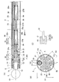
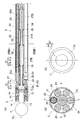
- (A) is a sectional view of the tip member and spindle guide portion of the remote control type actuator according to the first embodiment of the present invention
- (B) is a sectional view taken along the line IIB-IIB
- (C) is a sectional view of the tip member and the rotating shaft. It is a figure which shows a connection structure.
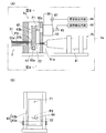
- (A) is a cross-sectional view of a tool rotation drive mechanism and a posture change drive mechanism of the remote operation type actuator
- (B) is a IIIB-IIIB cross-sectional view thereof.
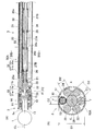
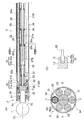
- (A) is a sectional view of a tip member and a spindle guide portion of a remote control type actuator according to a second embodiment of the present invention
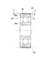
- (B) is a sectional view of the IVB-IVB. It is sectional drawing of the rotating shaft support member and guide pipe suppression means of the remote control type actuator. It is sectional drawing of the rotating shaft support member and guide pipe suppression means concerning a 1st modification. It is sectional drawing of the rotating shaft support member and guide pipe suppression means concerning a 2nd modification.
- (A) is a sectional view of a tip member and a spindle guide portion of a remote control type actuator according to a third embodiment of the present invention
- (B) is a VIIIB-VIIIB
- (C) is a VIIIC-VIIIC sectional view.
- (A) is a sectional view of a tip member and a spindle guide portion of a remote control type actuator according to a fourth embodiment of the present invention, (B) is its IXB-IXB, and (C) is its IXC-IXC sectional view.
- (A) is a sectional view of a tip member and a spindle guide portion of a remote control type actuator according to a fifth embodiment of the present invention
- (B) is a sectional view of the XIB-XIB.
- (A) is a sectional view of a tip member and a spindle guide part of a remote control type actuator according to a sixth embodiment of the present invention
- (B) is a plan view thereof
- (C) is a sectional view of XIC-XIC.
- (A) is a sectional view of a tip member and a spindle guide portion of a remote control type actuator according to a seventh embodiment of the present invention
- (B) is a plan view thereof
- (C) is a sectional view thereof taken along XIIC-XIIC.
- (A) is a sectional view of a tip member and a spindle guide portion of a remote control type actuator according to an eighth embodiment of the present invention
- (B) is a sectional view taken along line XIIIB-XIIIB.
- (A) is a sectional view of a tip member and a spindle guide portion of a remote control type actuator according to a ninth embodiment of the present invention
- (B) is a sectional view of XIVB-XIVB.
- (A) is a cross-sectional view of a tool rotation drive mechanism and a posture change drive mechanism of the remote operation type actuator
- (B) is a cross-sectional view of the XVB-XVB.
- (A) is a sectional view of a tip member and a spindle guide portion of a remote control type actuator according to a tenth embodiment of the present invention
- (B) is a sectional view of the XVIB-XVIB.
- (A) is a sectional view of a distal end member and a spindle guide portion of a remote control type actuator according to an eleventh embodiment of the present invention
- (B) is a sectional view of XVIIB-XVIIB
- (C) is a proximal end of a housing of the distal end member. It is the figure seen from the side.
- (A) is a sectional view of a tip member and a spindle guide portion of a remote control type actuator according to a twelfth embodiment of the present invention
- (B) is a sectional view of the XVIIIB-XVIIIB
- (C) is a sectional view of the tip member and a rotating shaft. It is a figure which shows a connection structure. It is sectional drawing of the spindle guide part of the remote control type actuator concerning 13th Embodiment of this invention.
- FIG. 1 (A) shows a remote control type actuator in which the spindle guide part 3 has a linear shape
- FIG. 1 (B) shows a remote control type actuator in which the spindle guide part 3 has a curved shape.
- this remote control type actuator includes a tip member 2 that holds a rotary tool 1, an elongated spindle guide portion 3 that is attached to the tip of the tip member 2 so that its posture can be freely changed, A drive unit housing 4a to which the base end of the spindle guide unit 3 is coupled, and a controller 5 for controlling the tool rotation drive mechanism 4b and the attitude change drive mechanism 4c in the drive unit housing 4a are provided.
- the drive unit housing 4a constitutes the drive unit 4 together with the built-in tool rotation drive mechanism 4b and posture changing drive mechanism 4c.
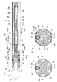
- FIG. 2 (A) is a cross-sectional view of the tip member 2 and the spindle guide portion 3 of the remote control type actuator shown in FIG. 1 (A).
- a spindle 13 is rotatably supported by a pair of bearings 12 inside a substantially cylindrical housing 11.
- the spindle 13 has a cylindrical shape with an open end, and the shank 1a of the tool 1 is inserted into the hollow portion in a fitted state, and the shank 1a is non-rotatably coupled by the rotation prevention pin 14.
- the tip member 2 is attached to the tip of the spindle guide portion 3 via the tip member connecting portion 15.
- the tip member connecting portion 15 is a means for supporting the tip member 2 so that the posture thereof can be freely changed, and includes a spherical bearing.
- the distal end member connecting portion 15 includes a guided portion 11 a that is a reduced inner diameter portion of the proximal end of the housing 11 and a hook-shaped portion of a retaining member 21 that is fixed to the distal end of the spindle guide portion 3. It is comprised with the guide part 21a.
- the guide surfaces F1 and F2 that are in contact with each other 11a and 21a are spherical surfaces having a center of curvature O located on the center line CL of the spindle 13 and having a smaller diameter toward the proximal end side.
- the spindle guide portion 3 has a rotating shaft 22 that transmits the rotational force of the tool rotation drive source 41 (FIG. 3A) in the drive portion housing 4a to the spindle 13.
- the rotating shaft 22 is a wire and can be elastically deformed to some extent.
- the material of the wire for example, metal, resin, glass fiber or the like is used.
- the wire may be a single wire or a stranded wire.
- the spindle 13 and the rotary shaft 22 are connected so as to be able to transmit rotation via a joint 23 such as a universal joint.
- the joint 23 includes a groove 13 a provided at the closed base end of the spindle 13 and a protrusion 22 a provided at the distal end of the rotating shaft 22 and engaged with the groove 13 a.
- the center of the connecting portion between the groove 13a and the protrusion 22a is at the same position as the center of curvature O of the guide surfaces F1 and F2.
- the rotating shaft 22 and the protrusion 22a may be configured as separate members.
- the spindle guide part 3 has an outer pipe 25 that is an outer part of the spindle guide part 3, and the rotating shaft 22 is located at the center of the outer pipe 25.
- the rotary shaft 22 is rotatably supported by rolling bearings 26 serving as a plurality of rotary shaft support means that are arranged apart from each other in the axial direction.
- spring elements 27A and 27B for generating a preload on the rolling bearing 26 are provided.
- the spring elements 27A and 27B are, for example, compression coil springs.
- the retaining member 21 is fixed to the pipe end portion 25a of the outer pipe 25 by a fixing pin 28, and rotatably supports the distal end portion of the rotary shaft 22 via a rolling bearing 29 at the distal end inner peripheral portion thereof.
- the pipe end portion 25a may be a separate member from the outer pipe 25 and may be joined by welding or the like.
- one guide pipe 30 penetrating at both ends is provided. Inside the guide hole 30 a which is the inner diameter hole of the guide pipe 30, the wire 31 a and the both ends thereof are provided.
- a posture operation member 31 composed of a columnar pin 31b is inserted in such a manner as to be able to advance and retreat.
- the distal end of the columnar pin 31b on the distal end member 2 side is spherical, and is in contact with the proximal end surface 11b of the housing 11 which is a contact surface with the posture operation member 31 of the distal end member 2.
- the base end surface 11b of the housing 11 is an inclined surface that is closer to the spindle guide portion 3 side toward the outer diameter side.
- the tip of the columnar pin 31b on the drive unit housing 4a side is also spherical, and is in contact with a side surface of a lever 43b (FIG. 3A) described later.
- the columnar pin 31b may be omitted, and the posture operation member 31 may be configured with only one wire 31a.
- compression is provided between the proximal end surface of the housing 11 of the distal end member 2 and the distal end surface of the outer pipe 25 of the spindle guide portion 3 at a position 180 degrees relative to the circumferential position where the posture operation member 31 is located.
- a restoring elastic member 32 made of a coil spring is provided. The restoring elastic member 32 acts to urge the tip member 2 toward a predetermined posture.
- a plurality of pieces are provided on the same pitch circle C1 as the guide pipe 30 separately from the guide pipe 30.
- a reinforcing shaft 34 is arranged. These reinforcing shafts 34 are for ensuring the rigidity of the spindle guide portion 3.
- the reinforcing shaft 34 is a member whose outer diameter is the same as that of the guide pipe 30. The intervals between the guide pipe 30 and the reinforcing shaft 34 are equal.
- the outer diameter of the outer pipe 25 is D1
- the outer diameter of the guide pipe 30 and the reinforcing shaft 34 is D2
- the outer diameter of the rolling bearing 26 is D3
- the relation of D1 / 2 ⁇ D2 + D3 / 2 is established.
- the dimensions are set. That is, there is no gap or a negative gap between the outer pipe 25 and the guide pipe 30 and the reinforcing shaft 34 and between the guide pipe 30 and the reinforcing shaft 34 and the rolling bearing 26.
- the guide pipe 30 and the reinforcing shaft 34 are pressed against the inner diameter surface of the outer pipe 25 and are pressed against the outer diameter surface of the rolling bearing 26. Therefore, the guide pipe 30 and the reinforcing shaft 34 are suppressed from moving in the radial direction of the outer pipe 25 within the outer pipe 25. Further, the guide pipe 30 and the reinforcing shaft 34 are also difficult to move due to friction between the guide pipe 30 and the reinforcing shaft 34 and the contact surfaces of the outer pipe 25 and the rolling bearing 26. That is, in this embodiment, the outer pipe 25 and the rolling bearing 26 constitute the guide pipe suppressing means 50 that suppresses the movement of the guide pipe 30 in the outer pipe 25.
- the relationship is established by adjusting at least one of the inner diameter D1 of the outer pipe 25, the outer diameter D2 of the guide pipe 30 and the reinforcing shaft 34, and the outer diameter D3 of the rolling bearing 26.
- a plurality of types of guide pipes 30 and reinforcing shafts 34 having different outer diameters D2 are prepared, and suitable ones are selectively used.
- a plurality of rolling bearings 26 having different outer diameter dimensions D3 may be prepared, or a plurality of outer pipes 25 having different inner diameter dimensions D1 may be prepared. According to this method, since the dimensional accuracy of each component 25, 26, 30, 34 is not required to be high, the spindle guide portion 3 can be manufactured at a low cost.
- the spindle guide portion 3 when the spindle guide portion 3 is a curved remote control type actuator, the outer pipe 25, the guide pipe 30, and the reinforcing shaft 34 need to be curved, although illustration is omitted.
- the rotary shaft 22 is preferably made of a material that is easily deformed, and for example, a shape memory alloy is suitable.
- the spindle guide portion 3 has the same configuration as that of a linear shape.
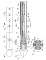
- FIG. 3A shows the tool rotation drive mechanism 4b and the posture change drive mechanism 4c in the drive unit housing 4a.
- the tool rotation drive mechanism 4 b includes a tool rotation drive source 41.
- the tool rotation drive source 41 is, for example, an electric motor, and its output shaft 41 a is coupled to the proximal end of the rotation shaft 22.
- the rotating shaft 22 passes through an opening 44 formed in the lever 43b described later.
- the posture changing drive mechanism 4 c includes a posture changing drive source 42 corresponding to the posture operating member 31.
- the posture changing drive source 42 is, for example, an electric linear actuator, and the movement of the output rod 42 a that moves in the left-right direction in FIG. 3A is transmitted to the posture operating member 31 through the force transmission mechanism 43.
- the boost transmission mechanism 43 has a lever 43b that is rotatable around a support shaft 43a.
- the force of the output rod 42a acts on an action point P1 of the lever 43b that is long from the support shaft 43a.
- the force is applied to the posture operation member 31 at the force point P ⁇ b> 2 having a short distance, and the output of the posture changing drive source 42 is increased and transmitted to the posture operation member 31.
- the posture changing drive source 42 may be a rotary motor. Further, instead of providing a linear actuator or the like, the posture of the tip member 2 may be remotely operated manually.
- the posture changing drive mechanism 4c is provided with a movement amount detector 45 for individually detecting the movement amount of each posture changing drive source 42.
- the detection value of the movement amount detector 45 is output to the posture detection means 46.
- the attitude detection means 46 detects the tilt attitude of the tip member 2 around the X axis (FIG. 2B) based on the output of the operation amount detector 45.
- the posture detection means 46 has relationship setting means (not shown) in which the relationship between the tilt posture and the output signal of the motion amount detector 45 is set by an arithmetic expression or a table, and the relationship is determined from the input output signal.
- the tilting posture is detected using setting means.
- the posture detection means 46 may be provided in the controller 5 (FIG. 1A) or may be provided in an external control device.
- the posture changing drive mechanism 4c is provided with a wattmeter 47 for individually detecting the amount of power supplied to the posture changing drive source 42, which is an electric actuator.
- the detected value of the supplied wattmeter 47 is output to the load detecting means 48.
- the load detection means 48 detects the load acting on the tip member 2 based on the output of the wattmeter 47.
- the load detection means 48 has relation setting means (not shown) in which the relation between the load and the output signal of the supplied wattmeter 47 is set by an arithmetic expression or a table, and the relation setting means is determined from the input output signal.
- the load is detected using.
- the load detecting means 48 may be provided in the controller 5 (FIG. 1A) or may be provided in an external control device.
- the controller 5 controls the tool rotation drive source 41 and the posture change drive source 42 based on the detected values of the posture detection means 46 and the load detection means 48.
- this remote control type actuator When the tool rotation drive source 41 in FIG. 3A is driven, the rotational force is transmitted to the spindle 13 in FIG. 2A through the rotation shaft 22, and the tool 1 rotates together with the spindle 13.
- the load acting on the tip member 2 when the tool 1 is rotated to cut bone or the like is detected by the load detection means 48 from the detection value of the wattmeter 47 shown in FIG. In accordance with the load value detected in this way, the load acting on the tip member 2 is properly maintained by controlling the feed amount of the entire remote control type actuator and the posture change of the tip member 2 to be described later. Can cut bone.
- the posture changing drive source 42 is driven to change the posture of the tip member 2 by remote control.
- the posture operation member 31 in FIG. 2A is advanced to the distal end side by the posture change drive source 42
- the housing 11 of the distal member 2 is pushed by the posture operation member 31, and the distal member 2 is moved to the position shown in FIG. In A)
- the posture is changed along the guide surfaces F1 and F2 to the side where the front end side is directed downward.
- the posture operation member 31 is retracted by the posture changing drive source 42
- the housing 11 of the tip member 2 is pushed back by the elastic repulsive force of the restoring elastic member 32, and the tip member 2 is shown in FIG.
- the posture is changed along the guide surfaces F1 and F2 to the side facing upward.
- the pressure of the posture operation member 31, the elastic repulsive force of the restoring elastic member 32, and the reaction force from the retaining member 21 act on the tip member connecting portion 15, and the balance of these acting forces
- the posture of the tip member 2 is determined.
- the posture of the tip member 2 is detected by the posture detection means 46 from the detection value of the movement amount detector 45 (FIG. 3A). Therefore, the posture of the tip member 2 can be appropriately controlled by remote operation.
- proximal end surface 11b of the housing 11 of the distal end member 2 is an inclined surface closer to the spindle guide portion 3 side toward the outer diameter side, when the attitude operating member 31 pushes the proximal end surface 11b of the housing 11, the attitude operating member The base end surface 11b of the housing 11 is slippery with respect to 31 and the housing 11 can be smoothly changed in posture.
- the posture operation member 31 Since the posture operation member 31 is inserted through the guide hole 30a of the guide pipe 30, the posture operation member 31 does not shift in the direction intersecting the longitudinal direction and can always act properly on the tip member 2. Thus, the posture changing operation of the tip member 2 is accurately performed. Further, since the posture operation member 31 is made of a wire and is flexible, the posture changing operation of the tip member 2 is reliably performed even if the spindle guide portion 3 is curved. Furthermore, since the center of the connecting portion between the spindle 13 and the rotating shaft 22 is at the same position as the center of curvature O of the guide surfaces F1 and F2, a force for pushing and pulling against the rotating shaft 22 by changing the posture of the tip member 2 is increased. Accordingly, the posture of the tip member 2 can be changed smoothly.
- the guide pipe restraining means 50 for restraining the guide pipe 30 from moving in the outer pipe 25 is provided, the rigidity of the guide pipe 30 is kept high. Thereby, the displacement or force of the attitude changing drive source 42 provided in the drive unit housing 4a can be accurately transmitted to the tip member 2, and the positioning accuracy of the tool 1 is good.
- the displacement or force of the posture changing drive source 42 is transmitted to the tip member 2 via the posture operation member 31 in the guide pipe 30 in the course of the displacement or force. Since the pipe 30 escapes in the radial direction, the displacement or force of the posture changing drive source 42 is not accurately transmitted to the tip member 2, and the positioning accuracy of the tool 1 is deteriorated.
- the rotary shaft 22 is rotatably supported by a rolling bearing 26 that is a rotary shaft support member. Therefore, the rotary shaft 22 is rotated at a high speed so that the rotation of the tool rotation drive source 41 is applied to the spindle 13. It is possible to communicate. Since the preload is applied to the rolling bearing 26 by the spring elements 27A and 27B, the supporting rigidity of the rolling bearing 26 is high and suitable for rotating the rotating shaft 22 at high speed. Since the spring elements 27A and 27B are provided between the adjacent rolling bearings 26, the spring elements 27A and 27B can be provided without increasing the diameter of the spindle guide portion 3. Thus, since the rotating shaft 22 can be rotated at a high speed, the tool 1 can be processed at a high speed. Therefore, the surface to be cut can be finished cleanly, and the cutting resistance acting on the tool 1 can be reduced.
- the elongated spindle guide portion 3 needs to be provided with the rotating shaft 22 and the posture operation member 31 in a protected state.
- the rotating shaft 22 is provided at the center of the outer pipe 25.
- This remote-operated actuator is used, for example, to cut the medullary cavity of bone in artificial joint replacement surgery.
- all or part of the tip member 2 shown in FIG. Used by inserting into the body. For this reason, if the posture of the tip member 2 can be changed by remote control as described above, the bone can be processed while the tool 1 is always held in an appropriate posture, and the artificial joint insertion hole is finished with high accuracy. Can do.
- the spindle guide part 3 has a curved shape, it may be possible to insert the tip member 2 to the back of a bone that is difficult to reach with a linear shape.
- the spindle guide portion 3 shown in FIGS. 1 (A) and 1 (B) can be used in a precise manner when machining a prosthetic joint insertion hole in a prosthetic joint replacement surgery by properly using a linear guide and a curved spindle guide 3 respectively. it can.
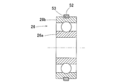
- the guide pipe suppressing means 50A in this embodiment has a different configuration from the guide pipe suppressing means 50 of the first embodiment described above. That is, as shown in FIG. 5, there is a gap 51 between the guide pipe 30 and the reinforcing shaft 34 and the rolling bearing 26, and an annular surface is formed on the outer diameter surface of the outer ring 26 b of the rolling bearing 26 so as to fill the gap 51.
- An elastic member 52 is provided.
- the elastic member 52 has a wide band shape and covers the entire axial direction of the outer diameter surface of the outer ring 26b.
- the material of the elastic member 52 is preferably a material having a low hardness. For example, a rubber material such as silicon rubber or a resin material such as fluororesin is used.
- the inner diameter D1 of the outer pipe 25, the outer diameter D2 of the guide pipe 30 and the reinforcing shaft 34 as the same outer diameter member which is the same member as the outer diameter.
- the dimensions are set so that D1 / 2 ⁇ D2 + D3 / 2. That is, there is no gap between the outer pipe 25 and the guide pipe 30 and the reinforcing shaft 34, and between the guide pipe 30 and the reinforcing shaft 34 and the rolling bearing 26, or a regular gap. Then, the thickness T of the elastic member 52 when no external force is applied is made larger than the gap dimension ⁇ .
- the elastic member 52 When the elastic member 52 is provided, the elastic member 52 is elastically deformed according to the gap 51, whereby the guide pipe 30 and the reinforcing shaft 34 are pressed against the inner diameter surface of the outer pipe 25. Therefore, the guide pipe 30 and the reinforcing shaft 34 are restrained from moving in the radial direction of the outer pipe 25 within the outer pipe 25. Further, the guide pipe 30 and the reinforcing shaft 34 are hardly moved by friction between the contact surfaces of the guide pipe 30 and the reinforcing shaft 34 and the outer pipe 25. That is, in this embodiment, the outer pipe 25, the rolling bearing 26, and the elastic member 52 constitute guide pipe suppressing means 50 ⁇ / b> A that suppresses the movement of the guide pipe 30 in the outer pipe 25.
- FIG. 6 shows a first modification of the elastic member as the guide pipe suppressing means.
- the elastic member 52 has a narrow band shape and is fitted in an annular groove 53 provided on the outer diameter surface of the outer ring 26 b of the rolling bearing 26. By fitting the elastic member 52 into the annular groove 53, it is possible to prevent the elastic member 52 from being detached from the outer diameter surface of the outer ring 26b.
- FIG. 7 shows a second modification of the elastic member.
- the elastic member 52 includes two O-rings 52a, and each O-ring 52a is fitted into an annular groove 53 provided on the outer diameter surface of the outer ring 26b of the rolling bearing 26. If the elastic member 52 is composed of the O-ring 52a, the elastic member 52 can be easily provided on the outer diameter surface of the outer ring 26b, and the assemblability is good.
- the elastic member 52 since the elastic member 52 is composed of two O-rings 52a, the rolling bearing 26 can be stably fixed, and even if a moment load is applied to the rolling bearing 26, it is supported at two points. Therefore, the moment load or the like acting on the rolling bearing 26 due to the deformation of the O-ring 52a can be reduced without extremely reducing the support rigidity.
- the guide pipe suppression means 50B in this embodiment has a different configuration from the guide pipe suppression means 50 of the first embodiment described above. That is, as shown in FIG. 8A, the guide pipe restraining means 50B is provided with a guide pipe contact member 55 in contact with the guide pipe 30 and the reinforcing shaft 34 in a part between the adjacent rolling bearings 26. is there.
- the guide pipe contact member 55 has a shape that makes contact with the inner diameter side surfaces of the guide pipe 30 and the reinforcing shaft 34 with respect to the outer pipe 25.
- the axial position where the guide pipe contact member 55 is provided is the axial position where the inner ring spring element 27A is disposed, and the inner diameter of the guide pipe contact member 55 is larger than the outer diameter of the inner ring spring element 27A. It is enlarged. Thereby, interference with spring element 27A, 27B and the guide pipe contact member 55 can be avoided.
- one and five guide pipes 30 and reinforcing shafts 34 are respectively arranged as in the first embodiment.
- the guide pipe 30 and the reinforcing shaft 34 can be pressed against the inner diameter surface of the outer pipe 25.
- the diameter of a circle C2 connecting the bottoms of the recesses 55a into which the guide pipe 30 and the reinforcing shaft 34 are fitted in the guide pipe contact member 55 is D4
- the dimensions are set so that D1 / 2 ⁇ D2 + D4 / 2.
- the guide pipe suppressing means 50C in this embodiment has a different configuration from the guide pipe suppressing means 50 of the first embodiment described above. That is, as shown in FIG. 9A, the guide pipe suppressing means 50C is provided with a guide pipe contact member 55 that comes into contact with the guide pipe 30 and the reinforcing shaft 34. As shown in FIG. 9C, the outer diameter end of the guide pipe contact member 55 is extended until it hits the inner diameter surface of the outer pipe 25, and the outer diameter end is fixed to the outer shell pipe 25 by welding 56. is there.
- the guide pipe contact member 55 may be fixed to the outer pipe 25 by other methods such as brazing.
- the guide pipe suppressing means 50D in this embodiment has a configuration different from the guide pipe suppressing means 50 of the first embodiment described above. That is, as shown in FIG. 10 (A), the guide pipe restraining means 50D fixes at least one end of the guide pipe 30 to the outer pipe 25 or a member fixed to the outer pipe 25, respectively. The guide pipe 30 is prevented from moving in the outer pipe 25 by suppressing the movement of the guide pipe 30 in the axial direction. In this embodiment, the distal end portion of the guide pipe 30 is fixed to the hole portion 57 provided in the pipe end portion 25a of the outer pipe 25 by press-fitting.
- the proximal end portion of the guide pipe 30 is fixed by press-fitting into a groove portion 59 provided in a flange member 58 that is a member fixed to the outer shell pipe 25.
- Both end portions of the reinforcing shaft 34 are also fixed to the hole portion 57 of the pipe end portion 25a and the groove portion 59 of the flange member 58 by press-fitting.
- Both ends of the guide pipe 30 and the reinforcing shaft 34 may be fixed by screws, adhesion, welding or the like instead of press-fitting. Either can be fixed easily.
- an axial compressive force is applied to the guide pipe 30.
- the hole portion 57 of the pipe end portion 25 a and the groove portion 59 of the flange member 58 are compressive force applying means that applies an axial compressive force to the guide pipe 30. If the compressive force applying means is provided, the guide pipe 30 is deformed so as to eliminate the gap with the outer pipe 25, and the movement of the guide pipe 30 is suppressed. Moreover, since force is applied to the guide pipe 30 from both ends, movement in the axial direction of the guide pipe 30 is suppressed. Even if only one end is fixed without fixing both ends of the guide pipe 30, an effect of making the guide pipe 30 difficult to move in the outer pipe 25 can be obtained.
- This guide pipe suppression means 50D may be employed alone or in combination with any of the other guide pipe suppression means 50 to 50C described above.
- a wide band elastic member 52 is provided on the outer diameter surface of the rolling bearing 26.
- the flange member 58 is coupled to the drive unit housing 4a by a plurality of bolts 61 shown in FIG. 10A, and the spindle guide unit 3 can be attached to and detached from the drive unit housing 4a. It is. Specifically, the flange member 58 has a cylindrical convex portion 58a at the center portion of the base end surface, and the convex portion 58a is coupled to a concave portion (not shown) of the drive unit housing 4a.
- the plurality of bolts 61 are arranged in the circumferential direction, and their head portions 61a are brought into contact with the side surface of the flange member 58 opposite to the drive unit housing 4a, and the shaft portion 61b is connected to the bolt of the flange member 58. It is inserted through the insertion hole 62 and screwed into a bolt hole (not shown) of the drive unit housing 4a.
- the rotary shaft 22 is composed of a guide portion inner portion 22a in the spindle guide portion 3 and a housing inner portion 22b in the drive portion housing 4a.
- the guide portion inner portion 22a and the housing inner portion 22b are coupled to each other by a coupling 63. They are connected so as to be separable in the direction of the center and to transmit rotation around the axis.
- FIGS. 11A to 11C and FIGS. 12A to 12C respectively.
- 11A and 11B showing the sixth embodiment
- the peripheral wall of the outer pipe 25 is provided with a window portion 71 communicating with the inside and the outside
- the periphery of the window portion 71 in the outer pipe 25 is
- the guide pipe 30 is fixed by brazing 72.
- one and five guide pipes 30 and reinforcing shafts 34 are respectively arranged as in the first embodiment.
- the outer diameter of the outer pipe 25 is not provided on the peripheral wall of the outer pipe 25 without providing the window portion 71 (FIG. 11A).
- the outer pipe 25 and the guide pipe 30 are fixed by laser welding 73 from the surface side.
- the entire posture operation member 31 is made of a wire.
- one and five guide pipes 30 and reinforcing shafts 34 are respectively arranged as in the first embodiment.
- the guide pipe 30 can be prevented from moving in the outer pipe 25. Further, since the outer pipe 25 and the guide pipe 30 are fixed, the section modulus of the spindle guide portion 3 is increased and the rigidity is increased. Therefore, even if a force acts on the tip member 2, the spindle guide portion 3 is difficult to bend, and the positioning accuracy of the tip member 2 with respect to the drive portion housing 4a is improved.
- These guide pipe restraining means 50E or 50F according to the sixth or seventh embodiment may be employed alone or in combination with any of the other guide pipe restraining means 50 to 50D described above.
- this remote control type actuator is provided with two guide pipes 30 at circumferential positions that are in a phase of 180 degrees with respect to each other in the outer pipe 25, and an inner diameter hole of the guide pipe 30.
- a posture operation member 31 is inserted into a certain guide hole 30a so as to freely advance and retract.
- a plurality of reinforcing shafts 34 are arranged on the same pitch circle C ⁇ b> 1 as the guide pipe 30.
- the restoring elastic member 32 is not provided.
- Guide surfaces F1 and F2 shown in FIG. 13A are spherical surfaces whose center of curvature is point O, or cylindrical surfaces having an X axis passing through point O as an axis.
- the drive unit 4 (not shown) is provided with two posture change drive sources 42 (not shown) for individually moving the two posture operation members 31 forward and backward, and these two posture change drives.
- the posture of the tip member 2 is changed by driving the sources 42 in opposite directions. For example, when the upper posture operation member 31 in FIG. 13A is advanced to the distal end side and the lower posture operation member 31 is retracted, the upper posture operation member 31 pushes the housing 11 of the distal end member 2. Thus, the posture of the tip member 2 is changed along the guide surfaces F1 and F2 to the side where the tip side is directed downward. Conversely, when both posture operation members 31 are moved back and forth, the housing 11 of the tip member 2 is pushed by the lower posture operation member 31, and the tip member 2 is directed upward in FIG. 13A.
- the posture is changed along the guide surfaces F1 and F2 to the side.
- the pressure of the two upper and lower posture operating members 31 and the reaction force from the retaining member 21 are acting on the tip member connecting portion 15, and the posture of the tip member 2 is determined by the balance of these acting forces. Is done.
- the housing 11 of the tip member 2 is pressurized by the two posture operation members 31, so that the posture stability of the tip member 2 is improved as compared with the embodiment in which the pressure is applied by only one posture operation member 31. Can be increased.
- this remote control type actuator is provided with three guide pipes 30 at circumferential positions in the outer pipe 25 that form a phase of 120 degrees with each other.
- a posture operation member 31 (31U, 31L, 31R) is inserted into the guide hole 30a.
- reinforcing shafts 34 are arranged alternately with the guide pipe 30.
- Guide surfaces F1 and F2 shown in FIG. 14A are spherical surfaces whose center of curvature is a point O, and the tip member 2 can tilt in any direction.
- FIGS. 15A and 15B show a tool rotation drive mechanism 4b and a posture change drive mechanism 4c of the remote operation type actuator.
- the tool rotation drive mechanism 4b has the same configuration as that shown in FIG.
- the posture changing drive mechanism 4c shown in FIG. 15A includes three posture changing drive sources 42 (42U, 42) corresponding to the posture operating members 31 (31U, 31L, 31R) (FIG. 14B), respectively. 42L, 42R).
- the movements of the output rods 42 a of the posture changing drive sources 42 are individually transmitted to the posture operating members 31 via the force-increasing transmission mechanism 43.
- the booster transmission mechanism 43 includes levers 43b (43bU, 43bL, 43bR) that are independently rotatable around the support shaft 43a.
- each of the attitude change drive sources 42 includes an operation amount detector 45 (45U, 45L, 45R) for individually detecting the operation amount of the attitude change drive source 42, and an attitude change A power supply meter 47 (47U, 47L, 47R) for individually detecting the amount of power supplied to the drive source 42 is provided.
- each posture operation member 31 (31U, 31L, 31R) is moved forward and backward by driving each posture change drive source 42 (42U, 42L, 42R) in association with each other, and the posture change of the tip member 2 is performed. I do.
- the upper posture operation member 31U causes the tip member 2
- the distal end member 2 changes its posture along the guide surfaces F1 and F2 to the side where the distal end side faces downward in FIG.
- each posture changing drive source 42 is controlled so that the amount of advance / retreat of each posture operation member 31 is appropriate.
- the posture operation member 31 at three positions in the circumferential direction, the posture of the tip member 2 can be changed in the directions of the upper, lower, left and right axes (X axis, Y axis).
- the pressure of the three posture operating members 31 and the reaction force from the retaining member 21 are acting on the tip member connecting portion 15, and the posture of the tip member 2 is determined by the balance of these acting forces.
- the posture stability of the tip member 2 is high because the housing 11 of the tip member 2 is pressurized by the three posture operation members 31.
- the posture change drive mechanism 4c can be configured as shown in FIG. 15B, for example. That is, three posture change drive sources 42 (42U, 42L, 42R) for individually moving the posture operation members 31 (31U, 31L, 31R) forward and backward are arranged in parallel on the left and right sides, and each posture change drive source is provided.
- a lever 43b (43bU, 43bL, 43bR) corresponding to 42 is provided so as to be rotatable around a common support shaft 43a, and each lever 43b has an action point P1 (P1U, P1L, P1R) that is long from the support shaft 43a.
- each posture change drive source 42 The force of the output rod 42a of each posture change drive source 42 is applied, and the force is applied to the posture operation member 31 at a force point P2 (P2U, P2L, P2R) having a short distance from the support shaft 43a. Thereby, the output of each posture change drive source 42 can be increased and transmitted to the corresponding posture operation member 31.
- the rotary shaft 22 passes through an opening 44 formed in the lever 43bU for the upper posture operation member 31U.
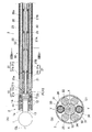
- the spindle guide portion 3 of the remote control type actuator of FIG. 16A has a hollow hole 24 of the outer pipe 25, a circular hole portion 24a in the center portion, and this circular hole portion 24a.
- 3 groove-like portions 24b that are recessed from the circumferential position forming a phase of 120 degrees to the outer diameter side.
- the peripheral wall at the tip of the groove-like portion 24b has a semicircular cross section.
- the rotating shaft 22 and the rolling bearing 26 are accommodated in the circular hole 24a, and the attitude
- the outer pipe 25 has the above-described cross-sectional shape, the thickness t of the outer pipe 25 other than the groove-like portion 24b is increased, and the secondary moment of the outer pipe 25 is increased. That is, the rigidity of the spindle guide portion 3 is increased. Thereby, the positioning accuracy of the tip member 2 can be improved and the machinability can be improved. Further, since the guide pipe 30 is disposed in the groove-like portion 24b, the guide pipe 30 can be easily positioned in the circumferential direction, and the assemblability is good.
- the fixed support member is the guide pipe 30 and the reinforcing shaft 34. However, in this embodiment, the fixed support member is only the guide pipe 30.
- a radial groove portion 11c is formed on the base end surface 11b (FIG. 10C) of the housing 11 of the distal end member 2 in FIG. 17A, and the posture operation member is formed on the bottom surface of the groove portion 11c. 31 spherical tips are in contact.
- the groove portion 11c and the posture operation member 31 constitute an anti-rotation mechanism 37, and the tip end portion 2 of the posture operation member 31 inserted into the groove portion 11c hits the side surface of the groove portion 11c. Rotation around 13 center lines CL is prevented.
- FIG. 17B shows an example in which there is one posture operation member 31, but the same can be said when there are a plurality of posture operation members 31.
- FIGS. 18 (A) to (C) This figure corresponds to FIG. 2 showing the first embodiment, and the same or corresponding parts are denoted by the same reference numerals, and detailed description thereof is omitted.
- the rolling bearing 26 which is a rotating shaft support member, is supported in a fixed state by the guide pipe 30 and the reinforcing shaft 34, which are fixed support members, and therefore vibration of the rotating shaft 22 can be suppressed. Therefore, damage to the rotating shaft 22 and the rolling bearing 26 can be prevented, and vibration and noise during use can be reduced.
- the rolling bearing 26 which is a rotating shaft support member
- a guide pipe suppressing means 50G comprising a gap adjusting member for adjusting the gap dimension between the rotating shaft support member 26 and the fixed support members 30 and 34 is provided.
- An elastic member 52 is used as the gap adjusting member. Therefore, it is possible to cope with a difference in the gap dimension ⁇ due to processing accuracy and the like, and the rolling bearing 26 can be reliably supported by the guide pipe 30 and the reinforcing shaft 34 in a fixed state.
- any shape of the spindle guide portion 3 is elastically deformed correspondingly, and the rolling bearing 26 is securely fixed by the guide pipe 30 and the reinforcing shaft 34. Can be supported.
- a gap adjusting member such as the elastic member 52
- the spindle guide portion 3 shown in FIG. 1A has a linear shape
- the gap between the rolling bearing 26 and the guide pipe 30 and the reinforcing shaft 34 If 51 (FIG. 5) is too wide, the rolling bearing 26 cannot be firmly supported by the guide pipe 30 and the reinforcing shaft 34, and the vibration of the rotating shaft 22 increases.
- the spindle guide portion 3 shown in FIG. 1B has a curved shape, if the gap 51 (FIG. 5) is narrow, the assemblability deteriorates. If the elastic member 52 is provided, such a problem is solved.
- the guide pipe 30 which is a member for forming the guide hole 30a is also used as the fixed support member, the number of parts can be reduced.
- FIG. 5 shows a cross section of the spindle guide portion of the remote control type actuator.
- the elastic member as in the twelfth embodiment is not provided, and the inner diameter dimension D1 of the outer pipe 25, the outer diameter dimension D2 of the guide pipe 30 and the reinforcing shaft 34 are used as the gap adjusting means 50H instead of the gap adjusting member.
- the gap dimension between the guide pipe 30 and the reinforcing shaft 34 and the rolling bearing 26 is adjusted.
- the gap 51 (FIG. 5) is preferably, for example, about plus 30 ⁇ m to minus 10 ⁇ m.
- the negative gap is good, but considering the assemblability when the spindle guide portion 3 has a curved shape, it may be necessary to make it a positive gap.
- the inner diameter D1 of the outer pipe 25 and the outer diameter D3 of the rolling bearing 26 are processed with high accuracy, a plurality of guide pipes 30 and reinforcing shafts 34 having different outer diameters D2 are prepared, and the spindle The gap dimension ⁇ can be adjusted by selectively using the guide pipe 30 and the reinforcing shaft 34 having the outer diameter D2 that matches the shape of the guide portion 3.
- the clearance dimension ⁇ can be adjusted in the same manner as described above by preparing a plurality of outer pipes 25 having different inner diameter dimensions D1. .
- the gap dimension is as small as possible.
- the spindle guide portion 3 has a curved shape, the assemblability deteriorates unless there is a certain gap dimension.
- the gap 51 can be a negative gap. If a negative gap is used, the rolling bearing 26 is firmly fixed, but an extremely negative gap impairs the assemblability. From experiments and the like, it was found that the gap size is preferably in the range of plus 100 ⁇ m to minus 10 ⁇ m.
- the rotary shaft support member is the rolling bearing 26.
- the rotary shaft support member may be a sliding bearing, or another member that can rotatably support the rotary shaft 22. Also good.
- the medical remote control actuator has been described above, but the present invention can be applied to remote control actuators for other purposes. For example, in the case of machining, drilling of a curved hole or cutting of a deep part inside the groove is possible.
- Each embodiment described above includes the following modes 1 to 11 that do not require the “guide pipe 30 having the guide hole 30a” of the present invention.
- the remote control type actuator includes an elongated spindle guide portion, a tip member attached to the tip of the spindle guide portion via a tip member connecting portion so that the posture can be freely changed, and a base end of the spindle guide portion And the tip member rotatably supports a spindle holding a tool, and the spindle guide portion rotates a tool rotation drive source provided in the drive unit housing.
- a rotation shaft that transmits the tip member to the spindle, and a guide hole that penetrates both ends of the shaft, and a posture operation member that changes the posture of the tip member by advancing and retracting with the tip contacting the tip member.
- a drive source for posture change which is inserted into the drive unit so as to advance and retract and moves the posture operation member forward and backward is provided in the drive unit housing, and the spindle guide
- the bone or the like is cut by the rotation of the tool provided on the tip member.
- the tip of the posture operation member acts on the tip member, so that the posture can be changed to the tip of the spindle guide portion via the tip member connecting portion.
- the position of the tip member attached to is changed.
- the posture changing drive source is provided in the drive portion housing on the proximal end side of the spindle guide portion, and the posture change of the tip member is performed by remote control. Since the posture operation member is inserted into the guide hole, the posture operation member does not shift in the direction intersecting the longitudinal direction, and can always act properly on the tip member, and the posture change operation of the tip member Is done accurately.
- the fixed support member ensures the rotation shaft support member. It can be supported in a fixed state. Further, regardless of the shape of the spindle guide portion, the rotary shaft support member can be reliably supported in a fixed state by the fixed support member, and the assembly and mass productivity are excellent. For example, when the gap adjusting means is not provided and the spindle guide portion is linear, if the gap between the rotary shaft support member and the fixed support member is too wide, the rotary shaft support member is firmly supported by the fixed support member. Cannot be performed, and the vibration of the rotating shaft increases.
- the rolling bearing is suitable for rotatably supporting the rotating shaft. If a spring element for applying a preload to the rolling bearings is provided between the adjacent rolling bearings as the rotating shaft support members, the supporting rigidity of the rolling bearings is increased, so that the rotating shaft can be rotated at a high speed.
- the fixed support member may be a member having the guide hole in the inner diameter portion.
- the rotating shaft support member is a plurality of rolling bearings arranged in the axial direction, and a spring element that applies a preload to the rolling bearings may be provided between adjacent rolling bearings.
- the gap adjusting means may be an elastic member provided on the outer periphery of the rotating shaft support member.
- the rotating shaft support member is a rolling bearing in which one or more annular grooves are provided on the outer diameter surface of the outer ring, and the elastic member as the gap adjusting means is an O fitted in the annular groove. It can be a ring.
- the elastic member as the gap adjusting means may be coated on the outer peripheral surface of the rotary shaft support member.
- the elastic member as the gap adjusting means may be in a compressed state in the assembled state of the spindle guide portion.
- the gap adjusting means includes the outer pipe of the outer pipe.
- the gap dimension can be adjusted by adjusting at least one of an inner diameter dimension, an outer diameter dimension of the guide pipe, and an outer diameter dimension of the rotating shaft support member.
- the gap size may be in the range of plus 100 ⁇ m to minus 10 ⁇ m.
- the spindle guide portion may have a curved portion.
Abstract
A remotely operated actuator which can change by remote operation the attitude of a tool mounted to the tip of an elongated pipe section and can accurately position the tip of the tool. The remotely operated actuator comprises an elongated spindle guide section (3), a tip member (2) mounted to the tip of the spindle guide section (3) in such a manner that the attitude of the tip member (2) is changeable, and a drive section housing (4a) to which the base end of the spindle guide section (3) is joined. The tip member (2) rotatably supports a spindle (13) for holding a tool (1). The spindle guide section (3) is provided with a rotating shaft (22) for transmitting rotation to the spindle (13) and also with an attitude operation member (31) for changing the attitude of the tip member (2), and the rotating shaft (22) and the attitude operation member (31) are provided within an outer shell pipe (25) which serves as the outer shell for the spindle guide section (3). The attitude operation member (31) is inserted through a guide pipe (30) located within the outer shell pipe (25) so that the attitude operation member (31) can advance and recede. The remotely operated actuator is also provided with a guide pipe restraining means (50) for preventing the guide pipe (30) from moving within the outer shell pipe (25).
Description
本出願は、2009年5月29日出願の特願2009-130460、および2009年5月29日出願の特願2009-130461の優先権を主張するものであり、その全体を参照により本願の一部をなすものとして引用する。
This application claims priority of Japanese Patent Application No. 2009-130460 filed on May 29, 2009 and Japanese Patent Application No. 2009-130461 filed on May 29, 2009, which is incorporated herein by reference in its entirety. Quote as part.
この発明は、工具の姿勢を遠隔操作で変更可能で、医療用、機械加工等の用途で用いられる遠隔操作型アクチュエータに関する。
The present invention relates to a remote operation type actuator that can change the posture of a tool by remote operation and is used for medical use, machining, and the like.
医療用として骨の加工に用いられたり、機械加工用としてドリル加工や切削加工に用いられたりする遠隔操作型アクチュエータがある。遠隔操作型アクチュエータは、直線形状や湾曲形状をした細長いパイプ部の先端に設けた工具を遠隔操作で制御する。ただし、従来の遠隔操作用アクチュエータは、工具の回転のみを遠隔操作で制御するだけであったため、医療用の場合、複雑な形状の加工や外からは見えにくい箇所の加工が難しかった。また、ドリル加工では、直線だけではなく、湾曲状の加工が可能なことが求められる。さらに、切削加工では、溝内部の奥まった箇所の加工が可能なことが求められる。以下、医療用を例にとって、遠隔操作型アクチュエータの従来技術と課題について説明する。
There are remote-operated actuators that are used for bone processing for medical purposes and drilling and cutting for mechanical processing. The remote operation type actuator remotely controls a tool provided at the end of a long and narrow pipe portion having a linear shape or a curved shape. However, since the conventional remote control actuator only controls the rotation of the tool by remote control, in the case of medical use, it was difficult to process a complicated shape or a part that is difficult to see from the outside. Further, in drilling, it is required that not only a straight line but also a curved shape can be processed. Furthermore, in the cutting process, it is required that a deep part inside the groove can be processed. Hereinafter, taking the medical use as an example, the prior art and problems of the remote control actuator will be described.
整形外科分野において、骨の老化等によって擦り減って使えなくなった関節を新しく人工のものに取り替える人工関節置換手術がある。この手術では、患者の生体骨を人工関節が挿入できるように加工する必要があるが、その加工には、術後の生体骨と人工関節との接着強度を高めるために、人工関節の形状に合わせて精度良く加工することが要求される。
In the field of orthopedics, there is an artificial joint replacement surgery in which a joint that has been worn out due to bone aging or the like is replaced with a new artificial one. In this operation, it is necessary to process the patient's living bone so that the artificial joint can be inserted. In order to increase the adhesive strength between the living bone and the artificial joint after the operation, the shape of the artificial joint is required. It is required to process with high accuracy.
例えば、股関節の人工関節置換手術では、大腿骨の骨の中心にある髄腔部に人工関節挿入用の穴を形成する。人工関節と骨との接触強度を保つには両者の接触面積を大きくとる必要があり、人工関節挿入用の穴は、骨の奥まで延びた細長い形状に加工される。このような骨の切削加工に用いられる医療用アクチュエータとして、細長いパイプ部の先端に工具を回転自在に設け、パイプ部の基端側に設けたモータ等の回転駆動源の駆動により、パイプ部の内部に配した回転軸を介して工具を回転させる構成のものがある(例えば特許文献1)。この種の医療用アクチュエータは、外部に露出した回転部分は先端の工具のみであるため、工具を骨の奥まで挿入することができる。
For example, in hip joint replacement surgery, an artificial joint insertion hole is formed in the medullary cavity at the center of the femur bone. In order to maintain the contact strength between the artificial joint and the bone, it is necessary to increase the contact area between them, and the hole for inserting the artificial joint is processed into an elongated shape extending to the back of the bone. As a medical actuator used for such a bone cutting process, a tool is rotatably provided at the distal end of an elongated pipe portion, and by driving a rotational drive source such as a motor provided on the proximal end side of the pipe portion, There exists a thing of the structure which rotates a tool via the rotating shaft arrange | positioned inside (for example, patent document 1). In this type of medical actuator, the rotating part exposed to the outside is only the tool at the tip, so that the tool can be inserted deep into the bone.
人工関節置換手術では、皮膚切開や筋肉の切断を伴う。すなわち、人体に傷を付けなければならない。その傷を最小限に抑えるためには、前記パイプ部は真っ直ぐでなく、適度に湾曲している方が良い場合がある。このような状況に対応するためのものとして、次のような従来技術がある。例えば、特許文献2は、パイプ部の中間部を2重に湾曲させて、パイプ部の先端側の軸心位置と基端側の軸心位置とをずらせたものである。このようにパイプ部の軸心位置が先端側と軸心側とでずれているものは、他にも知られている。また、特許文献3は、パイプ部を180度回転させたものである。
In artificial joint replacement surgery, skin incision and muscle cutting are involved. That is, the human body must be damaged. In order to minimize the scratches, the pipe part may not be straight but may be appropriately curved. In order to cope with such a situation, there are the following conventional techniques. For example, in Patent Document 2, an intermediate portion of a pipe portion is bent twice, and the axial center position on the distal end side and the axial center position on the proximal end side of the pipe portion are shifted. There are other known cases where the axial position of the pipe portion is shifted between the tip end side and the axial center side. In Patent Document 3, the pipe portion is rotated 180 degrees.
生体骨の人工関節挿入用穴に人工関節を嵌め込んだ状態で、生体骨と人工関節との間に広い隙間があると、術後の接着時間が長くなるため、前記隙間はなるべく狭いのが望ましい。また、生体骨と人工関節の接触面が平滑であることも重要であり、人工関節挿入用穴の加工には高い精度が要求される。しかし、パイプ部がどのような形状であろうとも、工具の動作範囲はパイプ部の形状の制約を受けるため、皮膚切開や筋肉の切断をできるだけ小さくしながら、生体骨と人工関節との間の隙間を狭くかつ両者の接触面が平滑になるように人工関節挿入用穴を加工するのは難しい。
If there is a wide gap between the living bone and the artificial joint with the artificial joint inserted in the artificial bone insertion hole of the living bone, the adhesion time after the operation becomes longer, so the gap is as narrow as possible. desirable. It is also important that the contact surface between the living bone and the artificial joint is smooth, and high accuracy is required for processing the hole for inserting the artificial joint. However, no matter what the shape of the pipe part, the operating range of the tool is limited by the shape of the pipe part. It is difficult to process the artificial joint insertion hole so that the gap is narrow and the contact surface of both is smooth.
一般に、人工関節置換手術が行われる患者の骨は、老化等により強度が弱くなっていることが多く、骨そのものが変形している場合もある。したがって、通常考えられる以上に、人工関節挿入用穴の加工は難しい。
Generally, the bones of patients undergoing artificial joint replacement are often weakened due to aging or the like, and the bones themselves may be deformed. Therefore, it is more difficult to process the artificial joint insertion hole than is normally conceivable.
そこで、本出願人は、人工関節挿入用穴の加工を比較的容易にかつ精度良く行えるようにすることを目的として、工具の姿勢を遠隔操作で変更可能とすることを試みた。工具の姿勢が変更可能であれば、パイプ部の形状に関係なく、工具を適正な姿勢に保持することができ、きめ細かな加工が可能になる。しかし、工具は細長いパイプ部の先端に設けられているため、工具の姿勢を変更させる機構を設ける上で制約が多く、それを克服するための工夫が必要である。なお、細長いパイプ部を有しない医療用アクチュエータでは、手で握る部分に対して工具が設けられた部分が姿勢変更可能なものがある(例えば特許文献4)が、遠隔操作で工具の姿勢を変更させるものは提案されていない。
Therefore, the present applicant tried to make it possible to change the posture of the tool by remote control for the purpose of relatively easily and accurately processing the hole for inserting the artificial joint. If the posture of the tool can be changed, the tool can be held in an appropriate posture regardless of the shape of the pipe portion, and fine machining can be performed. However, since the tool is provided at the tip of the elongated pipe portion, there are many restrictions in providing a mechanism for changing the posture of the tool, and a device for overcoming it is necessary. Note that some medical actuators that do not have an elongated pipe part can change the position of the part where the tool is provided relative to the hand-held part (for example, Patent Document 4), but the position of the tool can be changed remotely. Nothing has been proposed to make it happen.
工具の姿勢を遠隔操作で変更可能であっても、工具の先端位置を正確に位置決めできることが求められる。しかし、工具の姿勢を遠隔操作で変更可能にすると、パイプ部の内部に、工具に回転を伝達する回転軸と、工具の姿勢を変更させる姿勢変更部材とを設けることになり、パイプ部の構造が複雑になるため、工具の位置決め精度に影響を与える要素が増える。
っ て も Even if the tool posture can be changed by remote control, it is required to be able to accurately position the tip of the tool. However, if the posture of the tool can be changed by remote operation, a rotating shaft that transmits rotation to the tool and a posture changing member that changes the posture of the tool are provided inside the pipe portion, and the structure of the pipe portion This increases the number of factors that affect the positioning accuracy of the tool.
また、被切削面をきれいに仕上げるには、工具を高速回転させて加工することが必要である。それには、工具へ回転を伝達する回転軸を高速で回転させなければならない。しかし、回転軸が設けられる細長いパイプ部内は、工具の姿勢を変更させるための機構も設けられるため、構造が複雑になる。よって、パイプ部内に回転軸を機能的かつコンパクトに収容し、さらにパイプ部の組立性および量産性が良好な構成とすることが求められる。
Also, in order to finish the surface to be cut clean, it is necessary to rotate the tool at high speed. For this purpose, the rotating shaft that transmits the rotation to the tool must be rotated at high speed. However, since the mechanism for changing the posture of the tool is also provided in the elongated pipe portion provided with the rotation shaft, the structure becomes complicated. Therefore, it is required that the rotary shaft is accommodated functionally and compactly in the pipe portion, and the assembly and mass productivity of the pipe portion are good.
この発明は、細長いパイプ部の先端に設けられた工具の姿勢を遠隔操作で変更することができ、かつ工具の先端位置を精度良く位置決めできて、加工精度が良い遠隔操作型アクチュエータを提供することを目的としている。この発明の他の目的は、パイプ部内で回転軸を無理なく支持することができて、工具を高速回転させて切削加工することができ、さらに工具に回転を伝達する回転軸がパイプ部内に機能的かつコンパクトに収容されて、パイプ部の組立性および量産性が良好な遠隔操作型アクチュエータを提供することである。
The present invention provides a remote operation type actuator capable of changing the posture of a tool provided at the tip of a long and narrow pipe portion by remote operation and positioning the tip of the tool with high accuracy and having high machining accuracy. It is an object. Another object of the present invention is that the rotating shaft can be supported without difficulty in the pipe portion, the tool can be rotated at high speed for cutting, and the rotating shaft that transmits the rotation to the tool functions in the pipe portion. It is an object of the present invention to provide a remote control type actuator that is housed in a compact and compact manner and has good assembly and mass productivity of pipe parts.
この発明にかかる遠隔操作型アクチュエータは、細長形状のスピンドルガイド部と、このスピンドルガイド部の先端に先端部材連結部を介して姿勢変更自在に取付けられた先端部材と、前記スピンドルガイド部の基端が結合された駆動部ハウジングとを備え、前記先端部材は、工具を保持するスピンドルを回転自在に支持し、前記スピンドルガイド部は、前記駆動部ハウジング内に設けられた工具回転用駆動源の回転を前記スピンドルに伝達する回転軸と、両端に貫通したガイド孔とを内部に有し、先端が前記先端部材に接して進退動作することにより前記先端部材を姿勢変更させる姿勢操作部材を前記ガイド孔内に進退自在に挿通し、前記姿勢操作部材を進退させる姿勢変更用駆動源を前記駆動部ハウジング内に設け、前記スピンドルガイド部の外郭となる外郭パイプと、この外郭パイプの内部にあって内径孔が前記ガイド孔となるガイドパイプとを有し、外郭パイプ内でガイドパイプが動くことを抑制するガイドパイプ抑制手段を設けたものである。
A remote-control actuator according to the present invention includes an elongated spindle guide portion, a tip member attached to the tip of the spindle guide portion via a tip member connecting portion so that the posture can be freely changed, and a base end of the spindle guide portion And the tip member rotatably supports a spindle holding a tool, and the spindle guide portion rotates a tool rotation drive source provided in the drive unit housing. A rotation shaft that transmits the tip member to the spindle, and a guide hole that penetrates both ends of the shaft, and a posture operation member that changes the posture of the tip member by advancing and retracting with the tip contacting the tip member. An attitude change drive source is provided in the drive housing to pass through the interior of the drive section and move the attitude operation member forward and backward. A guide pipe suppressing means that has an outer pipe that is an outer shell of the outer pipe portion and a guide pipe that is inside the outer pipe and has an inner diameter hole serving as the guide hole, and that suppresses the movement of the guide pipe within the outer pipe. It is provided.
この構成によれば、先端部材に設けた工具の回転により、骨等の切削が行われる。その場合に、姿勢変更用駆動源により姿勢操作部材を進退させると、この姿勢操作部材の先端が先端部材に対し作用することにより、スピンドルガイド部の先端に先端部材連結部を介して姿勢変更自在に取付けられた先端部材が姿勢変更する。姿勢変更用駆動源は、スピンドルガイド部の基端側の駆動部ハウジング内に設けられており、上記先端部材の姿勢変更は遠隔操作で行われる。姿勢操作部材はガイド孔に挿通されているため、姿勢操作部材が長手方向と交差する方向に位置ずれすることがなく、常に先端部材に対し適正に作用することができ、先端部材の姿勢変更動作が正確に行われる。
According to this configuration, the bone or the like is cut by the rotation of the tool provided on the tip member. In this case, when the posture operation member is moved forward and backward by the posture change drive source, the tip of the posture operation member acts on the tip member, so that the posture can be changed to the tip of the spindle guide portion via the tip member connecting portion. The position of the tip member attached to is changed. The posture changing drive source is provided in the drive portion housing on the proximal end side of the spindle guide portion, and the posture change of the tip member is performed by remote control. Since the posture operation member is inserted into the guide hole, the posture operation member does not shift in the direction intersecting the longitudinal direction, and can always act properly on the tip member, and the posture change operation of the tip member Is done accurately.
外郭パイプ内でガイドパイプが動くことを抑制するガイドパイプ抑制手段を設けることで、ガイドパイプの剛性が増す。それにより、駆動部ハウジングに設けた姿勢変更用駆動源の変位もしくは力を正確に先端部材に伝えることができるようになり、工具の位置決め精度が向上する。外郭パイプ内でガイドパイプが動く場合、姿勢変更用駆動源の変位もしくは力がガイドパイプ内の姿勢操作部材を介して先端部材へ伝えられる過程で、前記変位もしくは力がガイドパイプの径方向に逃げる。そのため、姿勢変更用駆動源の変位もしくは力が先端部材に正確に伝わらず、工具の位置決め精度が悪くなる。この発明は、このようなガイドパイプの動きがガイドパイプ抑制手段で抑制されるため、工具の位置決め精度が向上する。
The rigidity of the guide pipe is increased by providing the guide pipe suppressing means for suppressing the movement of the guide pipe in the outer pipe. Accordingly, the displacement or force of the posture changing drive source provided in the drive unit housing can be accurately transmitted to the tip member, and the positioning accuracy of the tool is improved. When the guide pipe moves in the outer pipe, the displacement or force escapes in the radial direction of the guide pipe in the process in which the displacement or force of the posture changing drive source is transmitted to the tip member via the posture operation member in the guide pipe. . For this reason, the displacement or force of the posture changing drive source is not accurately transmitted to the tip member, and the positioning accuracy of the tool is deteriorated. In this invention, since the movement of the guide pipe is suppressed by the guide pipe suppressing means, the positioning accuracy of the tool is improved.
この発明において、前記ガイドパイプ抑制手段は、前記ガイドパイプを前記外郭パイプの内径面に押し当てる手段とすることができる。ガイドパイプ抑制手段でガイドパイプを外郭パイプの内径面に押し当てることにより、ガイドパイプと外郭パイプの隙間がなくなり、ガイドパイプが外郭パイプ内で動きにくくなる。また、ガイドパイプと外郭パイプの接触面間の摩擦により、ガイドパイプが動きにくくなる。
In the present invention, the guide pipe suppressing means may be means for pressing the guide pipe against the inner diameter surface of the outer pipe. By pressing the guide pipe against the inner diameter surface of the outer pipe with the guide pipe restraining means, the gap between the guide pipe and the outer pipe is eliminated, and the guide pipe becomes difficult to move in the outer pipe. Further, the guide pipe becomes difficult to move due to friction between the contact surfaces of the guide pipe and the outer pipe.
前記回転軸を回転自在に支持する回転軸支持部材を有する場合、前記ガイドパイプ抑制手段は、前記外郭パイプの内径寸法、前記ガイドパイプの外径寸法、および前記回転軸支持部材の外径寸法の少なくとも1つ以上を調整することにより、前記ガイドパイプを前記外郭パイプの内径面に押し当てる構成としてもよい。上記各部品の寸法の少なくとも1つ以上を調整することにより、ガイドパイプを外郭パイプの内径面に押し当てることができる。この構成は、各部品の寸法精度が高く要求されないので、低コストで製作することができる。
When the rotary shaft support member that rotatably supports the rotary shaft is provided, the guide pipe suppressing means has an inner diameter dimension of the outer pipe, an outer diameter dimension of the guide pipe, and an outer diameter dimension of the rotary shaft support member. The guide pipe may be pressed against the inner diameter surface of the outer pipe by adjusting at least one or more. The guide pipe can be pressed against the inner diameter surface of the outer pipe by adjusting at least one of the dimensions of the respective parts. Since this configuration does not require high dimensional accuracy of each component, it can be manufactured at low cost.
この発明において、前記外郭パイプ内の中心に前記回転軸が位置し、この回転軸と外郭パイプの内径面との間に、複数本の前記ガイドパイプ、または少なくとも1本のガイドパイプと外径がガイドパイプと同じである任意本数の部材(以下、「同外径部材」という)とが円周方向に並べて設けられている場合、前記外郭パイプの内径寸法をD1、前記ガイドパイプおよび前記同外径部材の外径寸法をD2、前記回転軸支持部材の外径寸法をD3とした場合、D1/2≦D2+D3/2の関係が成り立つようにするのがよい。つまり、外郭パイプとガイドパイプおよび同外径部材間、ならびにガイドパイプおよび同外径部材と回転軸支持部材間は、いずれも隙間が無いか、または負隙間にすることで、ガイドパイプおよび同外径部材が、外郭パイプの内径面に押し付けられ、かつ回転軸支持部材の外径面に押し付けられる。そのため、ガイドパイプおよび同外径部材は、外郭パイプ内で外郭パイプの径方向に動くことが抑制される。また、また、ガイドパイプおよび同外径部材と、外郭パイプおよび回転軸支持部材の接触面間の摩擦によっても、ガイドパイプおよび同外径部材が動きにくくなる。それにより、ガイドパイプの剛性を増すことができる。
In the present invention, the rotation shaft is located in the center of the outer pipe, and a plurality of the guide pipes or at least one guide pipe and the outer diameter are provided between the rotation shaft and the inner diameter surface of the outer pipe. When an arbitrary number of members that are the same as the guide pipe (hereinafter referred to as “the same outer diameter member”) are provided side by side in the circumferential direction, the inner diameter dimension of the outer pipe is D1, the guide pipe, and the outer pipe When the outer diameter dimension of the diameter member is D2, and the outer diameter dimension of the rotating shaft support member is D3, it is preferable that the relationship D1 / 2 ≦ D2 + D3 / 2 is satisfied. In other words, between the outer pipe and the guide pipe and the same outer diameter member, and between the guide pipe and the outer diameter member and the rotary shaft support member, there is no gap or a negative gap, so that the guide pipe The diameter member is pressed against the inner diameter surface of the outer pipe and is pressed against the outer diameter surface of the rotating shaft support member. Therefore, the guide pipe and the outer diameter member are restrained from moving in the radial direction of the outer pipe within the outer pipe. In addition, the guide pipe and the outer diameter member are less likely to move due to friction between the contact surfaces of the guide pipe and the outer diameter member and the outer pipe and the rotary shaft support member. Thereby, the rigidity of the guide pipe can be increased.
この発明において、前記回転軸を回転自在に支持する複数の回転軸支持部材を有し、前記ガイドパイプ抑制手段は、少なくとも1組の隣合う前記回転軸支持部材間に設けられ、前記ガイドパイプと接触するガイドパイプ接触部材であってもよい。少なくとも1組の隣合う回転軸支持部材間に、ガイドパイプと接触するガイドパイプ接触部材を設けることによっても、ガイドパイプの外郭パイプ内での動きを抑制できる。
In this invention, it has a plurality of rotating shaft support members which rotatably support the rotating shaft, and the guide pipe restraining means is provided between at least one pair of the adjacent rotating shaft support members, The guide pipe contact member which contacts may be sufficient. By providing a guide pipe contact member that contacts the guide pipe between at least one pair of adjacent rotating shaft support members, the movement of the guide pipe in the outer pipe can be suppressed.
前記ガイドパイプ接触部材は、前記ガイドパイプを前記外郭パイプの内径面に押し当てる作用を有するのがよい。ガイドパイプ接触部材でガイドパイプを外郭パイプの内径面に押し当てることにより、ガイドパイプと外郭パイプの隙間がなくなり、ガイドパイプが外郭パイプ内で動きにくくなる。また、ガイドパイプと外郭パイプの接触面間の摩擦により、ガイドパイプが動きにくくなる。
The guide pipe contact member may have an action of pressing the guide pipe against the inner diameter surface of the outer pipe. By pressing the guide pipe against the inner diameter surface of the outer pipe with the guide pipe contact member, there is no gap between the guide pipe and the outer pipe, and the guide pipe becomes difficult to move in the outer pipe. Further, the guide pipe becomes difficult to move due to friction between the contact surfaces of the guide pipe and the outer pipe.
前記回転軸支持部材は転がり軸受であり、隣合う転がり軸受間に、これら転がり軸受に対し予圧を与えるばね要素を設ける場合、前記ガイドパイプ接触部材を、前記ばね要素が転がり軸受の内輪側に配置されている軸方向箇所に設けるのがよい。隣合う転がり軸受間にばね要素が設けられている場合、ばね要素が転がり軸受の内輪側に配置されている軸方向箇所にガイドパイプ接触部材を設けることにより、ばね要素とガイドパイプ接触部材の干渉を避けることができる。
The rotary shaft support member is a rolling bearing, and when a spring element that applies preload to the rolling bearings is provided between adjacent rolling bearings, the guide pipe contact member is disposed on the inner ring side of the rolling bearing. It is good to provide in the axial direction location currently made. When a spring element is provided between adjacent rolling bearings, interference between the spring element and the guide pipe contact member is achieved by providing a guide pipe contact member at an axial position where the spring element is disposed on the inner ring side of the rolling bearing. Can be avoided.
この発明において、さらに、前記スピンドルガイド部内で前記回転軸を回転自在に支持する回転軸支持部材と、この回転軸支持部材を固定状態に支持する固定支持部材とを備え、前記ガイドパイプ抑制手段は、これら回転軸支持部材と固定支持部材間の隙間寸法を調整する隙間調整部材からなるものとしてもよい。
In this invention, it further comprises a rotary shaft support member that rotatably supports the rotary shaft in the spindle guide portion, and a fixed support member that supports the rotary shaft support member in a fixed state, and the guide pipe suppressing means comprises The gap adjusting member for adjusting the gap dimension between the rotating shaft support member and the fixed support member may be used.
この構成によれば、スピンドルガイド部内で回転軸を回転自在に支持する回転軸支持部材を設けたことにより、回転軸を高速回転させて工具回転用駆動源の回転をスピンドルに伝達することが可能である。そのため、工具を高速で回転させて加工を行うことができ、被切削面をきれいに仕上げられる。回転軸支持部材は固定支持部材により固定状態に支持されるため、回転軸の振動を抑えることができ、回転軸や回転軸支持部材の損傷を防げる。また、使用時のアクチュエータ全体の振動も小さくなるため、操作性が向上し、騒音も低減できる。
According to this configuration, by providing the rotation shaft support member that rotatably supports the rotation shaft in the spindle guide portion, it is possible to rotate the rotation shaft at a high speed and transmit the rotation of the tool rotation drive source to the spindle. It is. Therefore, it can process by rotating a tool at high speed, and a to-be-cut surface can be finished finely. Since the rotation shaft support member is supported in a fixed state by the fixed support member, vibration of the rotation shaft can be suppressed, and damage to the rotation shaft and the rotation shaft support member can be prevented. In addition, since vibration of the entire actuator during use is reduced, operability is improved and noise can be reduced.
また、回転軸支持部材と固定支持部材間の隙間寸法を調整する隙間調整部材が設けられているため、加工精度等による隙間寸法の違いに対応することができ、固定支持部材により回転軸支持部材を確実に固定状態に支持することができる。また、スピンドルガイド部がどのような形状であっても、それに対応して、固定支持部材により回転軸支持部材を確実に固定状態に支持することができ、組立性および量産性に優れる。例えば、隙間調整部材が設けられていない場合、スピンドルガイド部が直線形状のものでは、回転軸支持部材と固定支持部材間の隙間が広すぎると、固定支持部材により回転軸支持部材をしっかり支持することができず、回転軸の振動が大きくなる。その結果、回転軸や回転軸支持部材が損傷したり、使用時の振動や騒音が大きくなることがある。スピンドルガイド部が湾曲形状のものでは、前記隙間が狭いと組立性が悪くなる。隙間調整部材が設けられていれば、このような問題が解決される。
In addition, since the gap adjusting member for adjusting the gap dimension between the rotating shaft support member and the fixed support member is provided, it is possible to cope with the difference in the gap size due to processing accuracy and the like. Can be reliably supported in a fixed state. In addition, regardless of the shape of the spindle guide portion, the rotary shaft support member can be reliably supported in a fixed state by the fixed support member, and the assembly and mass productivity are excellent. For example, when the gap adjusting member is not provided and the spindle guide portion is linear, if the gap between the rotating shaft supporting member and the fixed supporting member is too wide, the rotating shaft supporting member is firmly supported by the fixed supporting member. Cannot be performed, and the vibration of the rotating shaft increases. As a result, the rotating shaft and the rotating shaft support member may be damaged, and vibration and noise during use may increase. When the spindle guide portion is curved, the assemblability deteriorates if the gap is narrow. If the gap adjustment member is provided, such a problem is solved.
この発明において、前記隙間調整部材は、前記回転軸支持部材の外周に設けた弾性部材とすることができる。隙間調整部材が弾性部材であれば、回転軸支持部材と固定支持部材間の隙間の大きさに応じて弾性部材が変形することにより、常に回転軸支持部材を安定して支持することができる。また、隙間調整部材が弾性部材であれば、回転軸の振動を弾性部材が吸収することで、回転軸の振動を低減させられる。
In this invention, the gap adjusting member can be an elastic member provided on the outer periphery of the rotating shaft support member. If the gap adjusting member is an elastic member, the elastic member is deformed according to the size of the gap between the rotary shaft support member and the fixed support member, so that the rotary shaft support member can always be stably supported. Further, if the gap adjusting member is an elastic member, the vibration of the rotating shaft can be reduced by the vibration of the rotating shaft being absorbed by the elastic member.
前記隙間調整部材が弾性部材である場合、前記回転軸支持部材は、外輪の外径面に1つ以上の環状溝が設けられた転がり軸受であり、前記弾性部材は、前記環状溝に嵌め込まれたOリングとすることができる。弾性部材をOリングとすると、転がり軸受の外周に弾性部材を容易に設けることができ、組立性が向上する。
When the gap adjusting member is an elastic member, the rotating shaft support member is a rolling bearing in which one or more annular grooves are provided on the outer diameter surface of the outer ring, and the elastic member is fitted into the annular groove. O-rings can be used. When the elastic member is an O-ring, the elastic member can be easily provided on the outer periphery of the rolling bearing, and assemblability is improved.
前記隙間調整部材としての弾性部材は、前記回転軸支持部材の外周面にコーティングされたものであってもよい。弾性部材を回転軸支持部材の外周面にコーティングされたものとすれば、回転軸支持部材の外周に弾性部材を容易に設けることができ、組立性が向上する。
The elastic member as the gap adjusting member may be a coating on the outer peripheral surface of the rotating shaft support member. If the elastic member is coated on the outer peripheral surface of the rotary shaft support member, the elastic member can be easily provided on the outer periphery of the rotary shaft support member, and the assemblability is improved.
前記隙間寸法は、プラス100μmないしマイナス10μmの範囲内とするのがよい。一般に、隙間寸法が大きすぎると、回転軸の振動が大きくなる。そのため、隙間寸法はなるべく小さいのが望ましいが、スピンドルガイド部が湾曲形状である場合、ある程度の隙間寸法がないと組立性が悪くなる。スピンドルガイド部が直線形状や直線に近い形状である場合は、隙間を負隙間にすることができる。負隙間にすれば、回転軸支持部材はしっかり固定されるが、極端な負隙間は組立性が損なわれる。実験等から、隙間寸法は上記範囲内とするのが好ましいことが分かった。
The gap size is preferably in the range of plus 100 μm to minus 10 μm. In general, if the gap dimension is too large, the vibration of the rotating shaft increases. For this reason, it is desirable that the gap dimension is as small as possible. However, when the spindle guide portion has a curved shape, the assemblability deteriorates unless there is a certain gap dimension. When the spindle guide portion has a linear shape or a shape close to a straight line, the gap can be a negative gap. If the negative gap is used, the rotary shaft support member is firmly fixed, but the assemblability of the extreme negative gap is impaired. From experiments and the like, it was found that the gap size is preferably within the above range.
この発明において、前記ガイドパイプの少なくとも一方の端部を、前記外郭パイプまたは外郭パイプに固定された部材に固定するのがよい。その場合、前記ガイドパイプの端部は、ねじ、圧入、接着、および溶接のうちの何れかにより固定することができる。ガイドパイプの少なくとも一方の端部を、外郭パイプまたは外郭パイプに固定された部材に固定することにより、ガイドパイプの軸方向の移動が抑制され、外郭パイプ内でガイドパイプが動きにくくなる。ねじ、圧入、接着、および溶接のうちの何れでも、ガイドパイプの端部を容易に固定することができる。
In this invention, it is preferable that at least one end of the guide pipe is fixed to the outer pipe or a member fixed to the outer pipe. In that case, the end of the guide pipe can be fixed by any one of screws, press-fitting, bonding, and welding. By fixing at least one end of the guide pipe to the outer pipe or a member fixed to the outer pipe, the movement of the guide pipe in the axial direction is suppressed, and the guide pipe becomes difficult to move in the outer pipe. The end of the guide pipe can be easily fixed by any of screw, press-fitting, adhesion, and welding.
この発明において、前記ガイドパイプに対し、軸方向の圧縮力を付与する圧縮力付与手段を設けるのがよい。圧縮力付与手段を設ければ、ガイドパイプが外郭パイプとの隙間をなくすように変形することで、ガイドパイプの移動が抑制される。また、ガイドパイプに両端から力を付与するため、ガイドパイプの軸方向への移動が抑制される。
In this invention, it is preferable to provide a compressive force applying means for applying an axial compressive force to the guide pipe. If the compressive force applying means is provided, the guide pipe is deformed so as to eliminate the gap with the outer pipe, thereby suppressing the movement of the guide pipe. Further, since force is applied to the guide pipe from both ends, movement of the guide pipe in the axial direction is suppressed.
この発明において、前記スピンドルガイド部は湾曲した箇所を有していてもよい。姿勢操作部材は可撓性であるため、スピンドルガイド部に湾曲した箇所があっても、ガイド孔内で進退させることができる。
In the present invention, the spindle guide portion may have a curved portion. Since the posture operation member is flexible, even if there is a curved portion in the spindle guide portion, it can be advanced and retracted in the guide hole.
この発明は、添付の図面を参考にした以下の好適な実施形態の説明から、より明瞭に理解されるであろう。しかしながら、実施形態および図面は単なる図示および説明のためのものであり、この発明の範囲を定めるために利用されるべきものではない。この発明の範囲は添付の請求の範囲によって定まる。添付図面において、複数の図面における同一の符号は、同一または相当する部分を示す。
この発明の第1実施形態にかかる遠隔操作型アクチュエータの概略構成を示す図である。(A),(B)はそれぞれスピンドルガイド部の形状が異なる遠隔操作型アクチュエータを示す。
(A)はこの発明の第1実施形態にかかる遠隔操作型アクチュエータの先端部材およびスピンドルガイド部の断面図、(B)はそのIIB-IIB断面図、(C)は先端部材と回転軸との連結構造を示す図である。
(A)は同遠隔操作型アクチュエータの工具回転用駆動機構および姿勢変更用駆動機構の断面図、(B)はそのIIIB-IIIB断面図である。
(A)はこの発明の第2実施形態にかかる遠隔操作型アクチュエータの先端部材およびスピンドルガイド部の断面図、(B)はそのIVB-IVB断面図である。
同遠隔操作型アクチュエータの回転軸支持部材およびガイドパイプ抑制手段の断面図である。
第1変形例にかかる回転軸支持部材およびガイドパイプ抑制手段の断面図である。
第2変形例にかかる回転軸支持部材およびガイドパイプ抑制手段の断面図である。
(A)はこの発明の第3実施形態にかかる遠隔操作型アクチュエータの先端部材およびスピンドルガイド部の断面図、(B)はそのVIIIB-VIIIB、(C)はそのVIIIC-VIIIC断面図である。
(A)はこの発明の第4実施形態にかかる遠隔操作型アクチュエータの先端部材およびスピンドルガイド部の断面図、(B)はそのIXB-IXB、(C)はそのIXC-IXC断面図である。
(A)はこの発明の第5実施形態にかかる遠隔操作型アクチュエータの先端部材およびスピンドルガイド部の断面図、(B)はそのXIB-XIB断面図である。
(A)はこの発明の第6実施形態にかかる遠隔操作型アクチュエータの先端部材およびスピンドルガイド部の断面図、(B)はその平面図、(C)はXIC-XIC断面図である。
(A)はこの発明の第7実施形態にかかる遠隔操作型アクチュエータの先端部材およびスピンドルガイド部の断面図、(B)はその平面図、(C)はそのXIIC-XIIC断面図である。
(A)はこの発明の第8実施形態にかかる遠隔操作型アクチュエータの先端部材およびスピンドルガイド部の断面図、(B)はそのXIIIB-XIIIB断面図である。
(A)はこの発明の第9実施形態にかかる遠隔操作型アクチュエータの先端部材およびスピンドルガイド部の断面図、(B)はそのXIVB-XIVB断面図である。
(A)は同遠隔操作型アクチュエータの工具回転用駆動機構および姿勢変更用駆動機構の断面図、(B)はそのXVB-XVB断面図である。
(A)はこの発明の第10実施形態にかかる遠隔操作型アクチュエータの先端部材およびスピンドルガイド部の断面図、(B)はそのXVIB-XVIB断面図である。
(A)はこの発明の第11実施形態にかかる遠隔操作型アクチュエータの先端部材およびスピンドルガイド部の断面図、(B)はそのXVIIB-XVIIB断面図、(C)は先端部材のハウジングを基端側から見た図である。
(A)はこの発明の第12実施形態にかかる遠隔操作型アクチュエータの先端部材およびスピンドルガイド部の断面図、(B)はそのXVIIIB-XVIIIB断面図、(C)は先端部材と回転軸との連結構造を示す図である。
この発明の第13実施形態にかかる遠隔操作型アクチュエータのスピンドルガイド部の断面図である。
The present invention will be more clearly understood from the following description of preferred embodiments with reference to the accompanying drawings. However, the embodiments and drawings are for illustration and description only and should not be used to define the scope of the present invention. The scope of the invention is defined by the appended claims. In the accompanying drawings, the same reference numerals in a plurality of drawings indicate the same or corresponding parts.
It is a figure which shows schematic structure of the remote control type actuator concerning 1st Embodiment of this invention. (A) and (B) show remote control type actuators having different spindle guide shapes. (A) is a sectional view of the tip member and spindle guide portion of the remote control type actuator according to the first embodiment of the present invention, (B) is a sectional view taken along the line IIB-IIB, and (C) is a sectional view of the tip member and the rotating shaft. It is a figure which shows a connection structure. (A) is a cross-sectional view of a tool rotation drive mechanism and a posture change drive mechanism of the remote operation type actuator, and (B) is a IIIB-IIIB cross-sectional view thereof. (A) is a sectional view of a tip member and a spindle guide portion of a remote control type actuator according to a second embodiment of the present invention, and (B) is a sectional view of the IVB-IVB. It is sectional drawing of the rotating shaft support member and guide pipe suppression means of the remote control type actuator. It is sectional drawing of the rotating shaft support member and guide pipe suppression means concerning a 1st modification. It is sectional drawing of the rotating shaft support member and guide pipe suppression means concerning a 2nd modification. (A) is a sectional view of a tip member and a spindle guide portion of a remote control type actuator according to a third embodiment of the present invention, (B) is a VIIIB-VIIIB, and (C) is a VIIIC-VIIIC sectional view. (A) is a sectional view of a tip member and a spindle guide portion of a remote control type actuator according to a fourth embodiment of the present invention, (B) is its IXB-IXB, and (C) is its IXC-IXC sectional view. (A) is a sectional view of a tip member and a spindle guide portion of a remote control type actuator according to a fifth embodiment of the present invention, and (B) is a sectional view of the XIB-XIB. (A) is a sectional view of a tip member and a spindle guide part of a remote control type actuator according to a sixth embodiment of the present invention, (B) is a plan view thereof, and (C) is a sectional view of XIC-XIC. (A) is a sectional view of a tip member and a spindle guide portion of a remote control type actuator according to a seventh embodiment of the present invention, (B) is a plan view thereof, and (C) is a sectional view thereof taken along XIIC-XIIC. (A) is a sectional view of a tip member and a spindle guide portion of a remote control type actuator according to an eighth embodiment of the present invention, and (B) is a sectional view taken along line XIIIB-XIIIB. (A) is a sectional view of a tip member and a spindle guide portion of a remote control type actuator according to a ninth embodiment of the present invention, and (B) is a sectional view of XIVB-XIVB. (A) is a cross-sectional view of a tool rotation drive mechanism and a posture change drive mechanism of the remote operation type actuator, and (B) is a cross-sectional view of the XVB-XVB. (A) is a sectional view of a tip member and a spindle guide portion of a remote control type actuator according to a tenth embodiment of the present invention, and (B) is a sectional view of the XVIB-XVIB. (A) is a sectional view of a distal end member and a spindle guide portion of a remote control type actuator according to an eleventh embodiment of the present invention, (B) is a sectional view of XVIIB-XVIIB, and (C) is a proximal end of a housing of the distal end member. It is the figure seen from the side. (A) is a sectional view of a tip member and a spindle guide portion of a remote control type actuator according to a twelfth embodiment of the present invention, (B) is a sectional view of the XVIIIB-XVIIIB, (C) is a sectional view of the tip member and a rotating shaft. It is a figure which shows a connection structure. It is sectional drawing of the spindle guide part of the remote control type actuator concerning 13th Embodiment of this invention.
この発明の第1実施形態を図1(A),(B)~図3(A),(B)と共に説明する。図1(A)はスピンドルガイド部3が直線形状の遠隔操作型アクチュエータを示し、同図(B)はスピンドルガイド部3が湾曲形状の遠隔操作型アクチュエータを示す。図1(A)において、この遠隔操作型アクチュエータは、回転式の工具1を保持する先端部材2と、この先端部材2が先端に姿勢変更自在に取付けられた細長形状のスピンドルガイド部3と、このスピンドルガイド部3の基端が結合された駆動部ハウジング4aと、この駆動部ハウジング4a内の工具回転用駆動機構4bおよび姿勢変更用駆動機構4cを制御するコントローラ5とを備える。駆動部ハウジング4aは、内蔵の工具回転用駆動機構4bおよび姿勢変更用駆動機構4cと共に駆動部4を構成する。
A first embodiment of the present invention will be described with reference to FIGS. 1 (A), (B) to FIGS. 3 (A), (B). FIG. 1 (A) shows a remote control type actuator in which the spindle guide part 3 has a linear shape, and FIG. 1 (B) shows a remote control type actuator in which the spindle guide part 3 has a curved shape. In FIG. 1A, this remote control type actuator includes a tip member 2 that holds a rotary tool 1, an elongated spindle guide portion 3 that is attached to the tip of the tip member 2 so that its posture can be freely changed, A drive unit housing 4a to which the base end of the spindle guide unit 3 is coupled, and a controller 5 for controlling the tool rotation drive mechanism 4b and the attitude change drive mechanism 4c in the drive unit housing 4a are provided. The drive unit housing 4a constitutes the drive unit 4 together with the built-in tool rotation drive mechanism 4b and posture changing drive mechanism 4c.
図2(A)は、図1(A)に示す遠隔操作型アクチュエータの先端部材2およびスピンドルガイド部3の断面図である。先端部材2は、略円筒状のハウジング11の内部に、一対の軸受12によりスピンドル13が回転自在に支持されている。スピンドル13は、先端側が開口した筒状で、中空部に工具1のシャンク1aが嵌合状態に挿入され、回り止めピン14によりシャンク1aが回転不能に結合される。この先端部材2は、先端部材連結部15を介してスピンドルガイド部3の先端に取付けられる。先端部材連結部15は、先端部材2を姿勢変更自在に支持する手段であり、球面軸受からなる。具体的には、先端部材連結部15は、ハウジング11の基端の内径縮径部からなる被案内部11aと、スピンドルガイド部3の先端に固定された抜け止め部材21の鍔状部からなる案内部21aとで構成される。両者11a,21aの互いに接する各案内面F1,F2は、スピンドル13の中心線CL上に曲率中心Oが位置し、基端側ほど径が小さい球面とされている。これにより、スピンドルガイド部3に対して先端部材2が抜け止めされるとともに、姿勢変更自在に支持される。
FIG. 2 (A) is a cross-sectional view of the tip member 2 and the spindle guide portion 3 of the remote control type actuator shown in FIG. 1 (A). In the tip member 2, a spindle 13 is rotatably supported by a pair of bearings 12 inside a substantially cylindrical housing 11. The spindle 13 has a cylindrical shape with an open end, and the shank 1a of the tool 1 is inserted into the hollow portion in a fitted state, and the shank 1a is non-rotatably coupled by the rotation prevention pin 14. The tip member 2 is attached to the tip of the spindle guide portion 3 via the tip member connecting portion 15. The tip member connecting portion 15 is a means for supporting the tip member 2 so that the posture thereof can be freely changed, and includes a spherical bearing. Specifically, the distal end member connecting portion 15 includes a guided portion 11 a that is a reduced inner diameter portion of the proximal end of the housing 11 and a hook-shaped portion of a retaining member 21 that is fixed to the distal end of the spindle guide portion 3. It is comprised with the guide part 21a. The guide surfaces F1 and F2 that are in contact with each other 11a and 21a are spherical surfaces having a center of curvature O located on the center line CL of the spindle 13 and having a smaller diameter toward the proximal end side. As a result, the tip member 2 is prevented from being detached from the spindle guide portion 3 and is supported so as to be freely changeable in posture.
スピンドルガイド部3は、駆動部ハウジング4a内の工具回転用駆動源41(図3(A))の回転力を前記スピンドル13へ伝達する回転軸22を有する。この例では、回転軸22はワイヤとされ、ある程度の弾性変形が可能である。ワイヤの材質としては、例えば金属、樹脂、グラスファイバー等が用いられる。ワイヤは単線であっても、撚り線であってもよい。図2(C)に示すように、スピンドル13と回転軸22とは、自在継手等の継手23を介して回転伝達可能に接続されている。継手23は、スピンドル13の閉塞した基端に設けられた溝13aと、回転軸22の先端に設けられ前記溝13aに係合する突起22aとで構成される。上記溝13aと突起22aとの連結箇所の中心は、前記案内面F1,F2の曲率中心Oと同位置である。回転軸22と突起22aは別部材として構成してもよい。
The spindle guide portion 3 has a rotating shaft 22 that transmits the rotational force of the tool rotation drive source 41 (FIG. 3A) in the drive portion housing 4a to the spindle 13. In this example, the rotating shaft 22 is a wire and can be elastically deformed to some extent. As the material of the wire, for example, metal, resin, glass fiber or the like is used. The wire may be a single wire or a stranded wire. As shown in FIG. 2C, the spindle 13 and the rotary shaft 22 are connected so as to be able to transmit rotation via a joint 23 such as a universal joint. The joint 23 includes a groove 13 a provided at the closed base end of the spindle 13 and a protrusion 22 a provided at the distal end of the rotating shaft 22 and engaged with the groove 13 a. The center of the connecting portion between the groove 13a and the protrusion 22a is at the same position as the center of curvature O of the guide surfaces F1 and F2. The rotating shaft 22 and the protrusion 22a may be configured as separate members.
スピンドルガイド部3は、このスピンドルガイド部3の外郭となる外郭パイプ25を有し、この外郭パイプ25の中心に前記回転軸22が位置する。回転軸22は、それぞれ軸方向に離れて配置された複数の回転軸支持手段としての転がり軸受26によって回転自在に支持されている。各転がり軸受26間には、これら転がり軸受26に予圧を発生させるためのばね要素27A,27Bが設けられている。ばね要素27A,27Bは、例えば圧縮コイルばねである。転がり軸受26の内輪26aに予圧を発生させる内輪用ばね要素27Aと、外輪26bに予圧を発生させる外輪用ばね要素27Bとがあり、これらが交互に配置されている。前記抜け止め部材21は、固定ピン28により外郭パイプ25のパイプエンド部25aに固定され、その先端内周部で転がり軸受29を介して回転軸22の先端部を回転自在に支持している。パイプエンド部25aは、外郭パイプ25と別部材とし、溶接等により結合してもよい。
The spindle guide part 3 has an outer pipe 25 that is an outer part of the spindle guide part 3, and the rotating shaft 22 is located at the center of the outer pipe 25. The rotary shaft 22 is rotatably supported by rolling bearings 26 serving as a plurality of rotary shaft support means that are arranged apart from each other in the axial direction. Between each rolling bearing 26, spring elements 27A and 27B for generating a preload on the rolling bearing 26 are provided. The spring elements 27A and 27B are, for example, compression coil springs. There are an inner ring spring element 27A for generating a preload on the inner ring 26a of the rolling bearing 26 and an outer ring spring element 27B for generating a preload on the outer ring 26b, which are alternately arranged. The retaining member 21 is fixed to the pipe end portion 25a of the outer pipe 25 by a fixing pin 28, and rotatably supports the distal end portion of the rotary shaft 22 via a rolling bearing 29 at the distal end inner peripheral portion thereof. The pipe end portion 25a may be a separate member from the outer pipe 25 and may be joined by welding or the like.
外郭パイプ25の内径面と回転軸22の間には、両端に貫通する1本のガイドパイプ30が設けられ、このガイドパイプ30の内径孔であるガイド孔30a内に、ワイヤ31aとその両端の柱状ピン31bとでなる姿勢操作部材31が進退自在に挿通されている。先端部材2側の柱状ピン31bの先端は球面状で、先端部材2の姿勢操作部材31との接触面であるハウジング11の基端面11bに当接している。ハウジング11の基端面11bは、外径側ほどスピンドルガイド部3側に近い傾斜面とされている。駆動部ハウジング4a側の柱状ピン31bの先端も球面状で、後述するレバー43b(図3(A))の側面に当接している。柱状ピン31bを省いて、1本のワイヤ31aのみで姿勢操作部材31を構成してもよい。
Between the inner diameter surface of the outer pipe 25 and the rotary shaft 22, one guide pipe 30 penetrating at both ends is provided. Inside the guide hole 30 a which is the inner diameter hole of the guide pipe 30, the wire 31 a and the both ends thereof are provided. A posture operation member 31 composed of a columnar pin 31b is inserted in such a manner as to be able to advance and retreat. The distal end of the columnar pin 31b on the distal end member 2 side is spherical, and is in contact with the proximal end surface 11b of the housing 11 which is a contact surface with the posture operation member 31 of the distal end member 2. The base end surface 11b of the housing 11 is an inclined surface that is closer to the spindle guide portion 3 side toward the outer diameter side. The tip of the columnar pin 31b on the drive unit housing 4a side is also spherical, and is in contact with a side surface of a lever 43b (FIG. 3A) described later. The columnar pin 31b may be omitted, and the posture operation member 31 may be configured with only one wire 31a.
上記姿勢操作部材31が位置する周方向位置に対し180度の位相の位置には、先端部材2のハウジング11の基端面とスピンドルガイド部3の外郭パイプ25の先端面との間に、例えば圧縮コイルばねからなる復元用弾性部材32が設けられている。この復元用弾性部材32は、先端部材2を所定姿勢側へ付勢する作用をする。
For example, compression is provided between the proximal end surface of the housing 11 of the distal end member 2 and the distal end surface of the outer pipe 25 of the spindle guide portion 3 at a position 180 degrees relative to the circumferential position where the posture operation member 31 is located. A restoring elastic member 32 made of a coil spring is provided. The restoring elastic member 32 acts to urge the tip member 2 toward a predetermined posture.
また、図2(A)に示すように、外郭パイプ25の内径面と回転軸22の間には、前記ガイドパイプ30とは別に、このガイドパイプ30と同一ピッチ円C1上に、複数本の補強シャフト34が配置されている。これらの補強シャフト34は、スピンドルガイド部3の剛性を確保するためのものである。補強シャフト34は、外径がガイドパイプ30と同径の部材である。ガイドパイプ30と補強シャフト34の配列間隔は等間隔とされている。
Further, as shown in FIG. 2A, between the inner diameter surface of the outer pipe 25 and the rotary shaft 22, a plurality of pieces are provided on the same pitch circle C1 as the guide pipe 30 separately from the guide pipe 30. A reinforcing shaft 34 is arranged. These reinforcing shafts 34 are for ensuring the rigidity of the spindle guide portion 3. The reinforcing shaft 34 is a member whose outer diameter is the same as that of the guide pipe 30. The intervals between the guide pipe 30 and the reinforcing shaft 34 are equal.
外郭パイプ25の内径寸法をD1、ガイドパイプ30および補強シャフト34の外径寸法をD2、転がり軸受26の外径寸法をD3とした場合、D1/2≦D2+D3/2の関係が成り立つように各寸法が設定されている。すなわち、外郭パイプ25とガイドパイプ30および補強シャフト34間、ならびにガイドパイプ30および補強シャフト34と転がり軸受26間は、いずれも隙間が無いか、または負隙間にしてある。
When the outer diameter of the outer pipe 25 is D1, the outer diameter of the guide pipe 30 and the reinforcing shaft 34 is D2, and the outer diameter of the rolling bearing 26 is D3, the relation of D1 / 2 ≦ D2 + D3 / 2 is established. The dimensions are set. That is, there is no gap or a negative gap between the outer pipe 25 and the guide pipe 30 and the reinforcing shaft 34 and between the guide pipe 30 and the reinforcing shaft 34 and the rolling bearing 26.
これにより、ガイドパイプ30および補強シャフト34が、外郭パイプ25の内径面に押し付けられ、かつ転がり軸受26の外径面に押し付けられる。そのため、ガイドパイプ30および補強シャフト34は、外郭パイプ25内で外郭パイプ25の径方向に動くことが抑制される。また、ガイドパイプ30および補強シャフト34と、外郭パイプ25および転がり軸受26の接触面間の摩擦によっても、ガイドパイプ30および補強シャフト34が動きにくくなる。つまり、この実施形態では、外郭パイプ25および転がり軸受26が、外郭パイプ25内でガイドパイプ30が動くことを抑制するガイドパイプ抑制手段50を構成している。
Thus, the guide pipe 30 and the reinforcing shaft 34 are pressed against the inner diameter surface of the outer pipe 25 and are pressed against the outer diameter surface of the rolling bearing 26. Therefore, the guide pipe 30 and the reinforcing shaft 34 are suppressed from moving in the radial direction of the outer pipe 25 within the outer pipe 25. Further, the guide pipe 30 and the reinforcing shaft 34 are also difficult to move due to friction between the guide pipe 30 and the reinforcing shaft 34 and the contact surfaces of the outer pipe 25 and the rolling bearing 26. That is, in this embodiment, the outer pipe 25 and the rolling bearing 26 constitute the guide pipe suppressing means 50 that suppresses the movement of the guide pipe 30 in the outer pipe 25.
詳しくは、外郭パイプ25の内径寸法D1、ガイドパイプ30および補強シャフト34の外径寸法D2、および転がり軸受26の外径寸法D3の少なくとも1つ以上を調整することで、前記関係が成り立つようにできる。例えば、外径寸法D2が異なる複数種のガイドパイプ30および補強シャフト34を用意しておき、その中から適したものを選択的に用いる。同様に、外径寸法D3が異なる複数の転がり軸受26を用意してもよく、あるいは、内径寸法D1が異なる複数の外郭パイプ25を用意してもよい。この方法によれば、各部品25,26,30,34の寸法精度が高く要求されないので、スピンドルガイド部3を低コストで製作することができる。
Specifically, the relationship is established by adjusting at least one of the inner diameter D1 of the outer pipe 25, the outer diameter D2 of the guide pipe 30 and the reinforcing shaft 34, and the outer diameter D3 of the rolling bearing 26. it can. For example, a plurality of types of guide pipes 30 and reinforcing shafts 34 having different outer diameters D2 are prepared, and suitable ones are selectively used. Similarly, a plurality of rolling bearings 26 having different outer diameter dimensions D3 may be prepared, or a plurality of outer pipes 25 having different inner diameter dimensions D1 may be prepared. According to this method, since the dimensional accuracy of each component 25, 26, 30, 34 is not required to be high, the spindle guide portion 3 can be manufactured at a low cost.
図1(B)のスピンドルガイド部3が湾曲形状の遠隔操作型アクチュエータの場合、図示は省略するが、外郭パイプ25、ガイドパイプ30、および補強シャフト34を湾曲形状とする必要がある。回転軸22は変形しやすい材質を用いるのが良く、例えば形状記憶合金が適する。他は、スピンドルガイド部3が直線形状のものと同じ構成である。
1B, when the spindle guide portion 3 is a curved remote control type actuator, the outer pipe 25, the guide pipe 30, and the reinforcing shaft 34 need to be curved, although illustration is omitted. The rotary shaft 22 is preferably made of a material that is easily deformed, and for example, a shape memory alloy is suitable. Other than that, the spindle guide portion 3 has the same configuration as that of a linear shape.
図3(A)は、駆動部ハウジング4a内の工具回転用駆動機構4bおよび姿勢変更用駆動機構4cを示す。工具回転用駆動機構4bは、工具回転用駆動源41を備える。工具回転用駆動源41は、例えば電動モータであり、その出力軸41aが前記回転軸22の基端に結合させてある。なお、回転軸22は、後記レバー43bに形成された開口44を貫通させてある。
FIG. 3A shows the tool rotation drive mechanism 4b and the posture change drive mechanism 4c in the drive unit housing 4a. The tool rotation drive mechanism 4 b includes a tool rotation drive source 41. The tool rotation drive source 41 is, for example, an electric motor, and its output shaft 41 a is coupled to the proximal end of the rotation shaft 22. The rotating shaft 22 passes through an opening 44 formed in the lever 43b described later.
姿勢変更用駆動機構4cは、姿勢操作部材31に対応する姿勢変更用駆動源42を備える。姿勢変更用駆動源42は、例えば電動リニアアクチュエータであり、図3(A)の左右方向に移動する出力ロッド42aの動きが、増力伝達機構43を介して前記姿勢操作部材31に伝達される。増力伝達機構43は、支軸43a回りに回動自在なレバー43bを有し、このレバー43bにおける支軸43aからの距離が長い作用点P1に出力ロッド42aの力が作用し、支軸43aからの距離が短い力点P2で姿勢操作部材31に力を与える構成であり、姿勢変更用駆動源42の出力が増力して姿勢操作部材31に伝達される。増力伝達機構43を設けると、小さな出力のリニアアクチュエータでも姿勢操作部材31に大きな力を与えることができるので、リニアアクチュエータの小型化が可能になる。姿勢変更用駆動源42は、回転モータであってもよい。また、リニアアクチュエータ等を設ける代わりに、手動により先端部材2の姿勢を遠隔操作してもよい。
The posture changing drive mechanism 4 c includes a posture changing drive source 42 corresponding to the posture operating member 31. The posture changing drive source 42 is, for example, an electric linear actuator, and the movement of the output rod 42 a that moves in the left-right direction in FIG. 3A is transmitted to the posture operating member 31 through the force transmission mechanism 43. The boost transmission mechanism 43 has a lever 43b that is rotatable around a support shaft 43a. The force of the output rod 42a acts on an action point P1 of the lever 43b that is long from the support shaft 43a. The force is applied to the posture operation member 31 at the force point P <b> 2 having a short distance, and the output of the posture changing drive source 42 is increased and transmitted to the posture operation member 31. If the boost transmission mechanism 43 is provided, a large force can be applied to the posture operation member 31 even with a linear actuator having a small output, and thus the linear actuator can be downsized. The posture changing drive source 42 may be a rotary motor. Further, instead of providing a linear actuator or the like, the posture of the tip member 2 may be remotely operated manually.
姿勢変更用駆動機構4cには、各姿勢変更用駆動源42の動作量をそれぞれ個別に検出する動作量検出器45が設けられている。この動作量検出器45の検出値は、姿勢検出手段46に出力される。姿勢検出手段46は、動作量検出器45の出力により、先端部材2のX軸(図2(B))回りの傾動姿勢を検出する。姿勢検出手段46は、上記傾動姿勢と動作量検出器45の出力信号との関係を演算式またはテーブル等により設定した関係設定手段(図示せず)を有し、入力された出力信号から前記関係設定手段を用いて傾動姿勢を検出する。この姿勢検出手段46は、コントローラ5(図1(A))に設けられたものであっても、あるいは外部の制御装置に設けられたものであってもよい。
The posture changing drive mechanism 4c is provided with a movement amount detector 45 for individually detecting the movement amount of each posture changing drive source 42. The detection value of the movement amount detector 45 is output to the posture detection means 46. The attitude detection means 46 detects the tilt attitude of the tip member 2 around the X axis (FIG. 2B) based on the output of the operation amount detector 45. The posture detection means 46 has relationship setting means (not shown) in which the relationship between the tilt posture and the output signal of the motion amount detector 45 is set by an arithmetic expression or a table, and the relationship is determined from the input output signal. The tilting posture is detected using setting means. The posture detection means 46 may be provided in the controller 5 (FIG. 1A) or may be provided in an external control device.
また、姿勢変更用駆動機構4cには、電動アクチュエータである姿勢変更用駆動源42に供給される電力量をそれぞれ個別に検出する供給電力計47が設けられている。この供給電力計47の検出値は、荷重検出手段48に出力される。荷重検出手段48は、供給電力計47の出力により、先端部材2に作用する荷重を検出する。荷重検出手段48は、上記荷重と供給電力計47の出力信号との関係を演算式またはテーブル等により設定した関係設定手段(図示せず)を有し、入力された出力信号から前記関係設定手段を用いて荷重を検出する。この荷重検出手段48は、コントローラ5(図1(A))に設けられたものであっても、あるいは外部の制御装置に設けられたものであってもよい。
The posture changing drive mechanism 4c is provided with a wattmeter 47 for individually detecting the amount of power supplied to the posture changing drive source 42, which is an electric actuator. The detected value of the supplied wattmeter 47 is output to the load detecting means 48. The load detection means 48 detects the load acting on the tip member 2 based on the output of the wattmeter 47. The load detection means 48 has relation setting means (not shown) in which the relation between the load and the output signal of the supplied wattmeter 47 is set by an arithmetic expression or a table, and the relation setting means is determined from the input output signal. The load is detected using. The load detecting means 48 may be provided in the controller 5 (FIG. 1A) or may be provided in an external control device.
コントローラ5は、前記姿勢検出手段46および荷重検出手段48の検出値に基づき、工具回転用駆動源41および姿勢変更用駆動源42を制御する。
The controller 5 controls the tool rotation drive source 41 and the posture change drive source 42 based on the detected values of the posture detection means 46 and the load detection means 48.
この遠隔操作型アクチュエータの動作を説明する。
図3(A)の工具回転用駆動源41を駆動すると、その回転力が回転軸22を介して図2(A)のスピンドル13に伝達されて、スピンドル13と共に工具1が回転する。工具1を回転させて骨等を切削加工する際に先端部材2に作用する荷重は、図3(A)の供給電力計47の検出値から、荷重検出手段48によって検出される。このように検出される荷重の値に応じて、遠隔操作型アクチュエータ全体の送り量や先端部材2の後述する姿勢変更を制御することにより、先端部材2に作用する荷重を適正に保った状態で骨の切削加工を行える。 The operation of this remote control type actuator will be described.
When the tool rotation drivesource 41 in FIG. 3A is driven, the rotational force is transmitted to the spindle 13 in FIG. 2A through the rotation shaft 22, and the tool 1 rotates together with the spindle 13. The load acting on the tip member 2 when the tool 1 is rotated to cut bone or the like is detected by the load detection means 48 from the detection value of the wattmeter 47 shown in FIG. In accordance with the load value detected in this way, the load acting on the tip member 2 is properly maintained by controlling the feed amount of the entire remote control type actuator and the posture change of the tip member 2 to be described later. Can cut bone.
図3(A)の工具回転用駆動源41を駆動すると、その回転力が回転軸22を介して図2(A)のスピンドル13に伝達されて、スピンドル13と共に工具1が回転する。工具1を回転させて骨等を切削加工する際に先端部材2に作用する荷重は、図3(A)の供給電力計47の検出値から、荷重検出手段48によって検出される。このように検出される荷重の値に応じて、遠隔操作型アクチュエータ全体の送り量や先端部材2の後述する姿勢変更を制御することにより、先端部材2に作用する荷重を適正に保った状態で骨の切削加工を行える。 The operation of this remote control type actuator will be described.
When the tool rotation drive
使用時には、姿勢変更用駆動源42を駆動させて、遠隔操作で先端部材2の姿勢変更を行う。例えば、姿勢変更用駆動源42により図2(A)の姿勢操作部材31を先端側へ進出させると、姿勢操作部材31によって先端部材2のハウジング11が押されて、先端部材2は図2(A)において先端側が下向きとなる側へ案内面F1,F2に沿って姿勢変更する。逆に、姿勢変更用駆動源42により姿勢操作部材31を後退させると、復元用弾性部材32の弾性反発力によって先端部材2のハウジング11が押し戻され、先端部材2は図2(A)において先端側が上向きとなる側へ案内面F1,F2に沿って姿勢変更する。その際、先端部材連結部15には、姿勢操作部材31の圧力、復元用弾性部材32の弾性反発力、および抜け止め部材21からの反力が作用しており、これらの作用力の釣り合いにより先端部材2の姿勢が決定される。先端部材2の姿勢は、動作量検出器45(図3(A))の検出値から、姿勢検出手段46によって検出される。そのため、遠隔操作で先端部材2の姿勢を適正に制御できる。
At the time of use, the posture changing drive source 42 is driven to change the posture of the tip member 2 by remote control. For example, when the posture operation member 31 in FIG. 2A is advanced to the distal end side by the posture change drive source 42, the housing 11 of the distal member 2 is pushed by the posture operation member 31, and the distal member 2 is moved to the position shown in FIG. In A), the posture is changed along the guide surfaces F1 and F2 to the side where the front end side is directed downward. On the other hand, when the posture operation member 31 is retracted by the posture changing drive source 42, the housing 11 of the tip member 2 is pushed back by the elastic repulsive force of the restoring elastic member 32, and the tip member 2 is shown in FIG. The posture is changed along the guide surfaces F1 and F2 to the side facing upward. At that time, the pressure of the posture operation member 31, the elastic repulsive force of the restoring elastic member 32, and the reaction force from the retaining member 21 act on the tip member connecting portion 15, and the balance of these acting forces The posture of the tip member 2 is determined. The posture of the tip member 2 is detected by the posture detection means 46 from the detection value of the movement amount detector 45 (FIG. 3A). Therefore, the posture of the tip member 2 can be appropriately controlled by remote operation.
先端部材2のハウジング11の基端面11bが外径側ほどスピンドルガイド部3側に近い傾斜面とされているため、姿勢操作部材31がハウジング11の基端面11bを押したときに、姿勢操作部材31に対してハウジング11の基端面11bが滑りやすく、ハウジング11の円滑な姿勢変更ができる。
Since the proximal end surface 11b of the housing 11 of the distal end member 2 is an inclined surface closer to the spindle guide portion 3 side toward the outer diameter side, when the attitude operating member 31 pushes the proximal end surface 11b of the housing 11, the attitude operating member The base end surface 11b of the housing 11 is slippery with respect to 31 and the housing 11 can be smoothly changed in posture.
姿勢操作部材31はガイドパイプ30のガイド孔30aに挿通されているため、姿勢操作部材31が長手方向と交差する方向に位置ずれすることがなく、常に先端部材2に対し適正に作用することができ、先端部材2の姿勢変更動作が正確に行われる。また、姿勢操作部材31はワイヤからなり可撓性であるため、スピンドルガイド部3が湾曲していても先端部材2の姿勢変更動作が確実に行われる。さらに、スピンドル13と回転軸22との連結箇所の中心が案内面F1,F2の曲率中心Oと同位置であるため、先端部材2の姿勢変更によって回転軸22に対して押し引きする力がかからず、先端部材2が円滑に姿勢変更できる。
Since the posture operation member 31 is inserted through the guide hole 30a of the guide pipe 30, the posture operation member 31 does not shift in the direction intersecting the longitudinal direction and can always act properly on the tip member 2. Thus, the posture changing operation of the tip member 2 is accurately performed. Further, since the posture operation member 31 is made of a wire and is flexible, the posture changing operation of the tip member 2 is reliably performed even if the spindle guide portion 3 is curved. Furthermore, since the center of the connecting portion between the spindle 13 and the rotating shaft 22 is at the same position as the center of curvature O of the guide surfaces F1 and F2, a force for pushing and pulling against the rotating shaft 22 by changing the posture of the tip member 2 is increased. Accordingly, the posture of the tip member 2 can be changed smoothly.
外郭パイプ25内でガイドパイプ30が動くことを抑制するガイドパイプ抑制手段50が設けられているため、ガイドパイプ30の剛性が高く保たれている。それにより、駆動部ハウジング4aに設けた姿勢変更用駆動源42の変位もしくは力を正確に先端部材2に伝えることができ、工具1の位置決め精度が良い。外郭パイプ25内でガイドパイプ30が動く場合、姿勢変更用駆動源42の変位もしくは力がガイドパイプ30内の姿勢操作部材31を介して先端部材2へ伝えられる過程で、前記変位もしくは力がガイドパイプ30の径方向に逃げるため、姿勢変更用駆動源42の変位もしくは力が先端部材2に正確に伝わらず、工具1の位置決め精度が悪くなるのである。
Since the guide pipe restraining means 50 for restraining the guide pipe 30 from moving in the outer pipe 25 is provided, the rigidity of the guide pipe 30 is kept high. Thereby, the displacement or force of the attitude changing drive source 42 provided in the drive unit housing 4a can be accurately transmitted to the tip member 2, and the positioning accuracy of the tool 1 is good. When the guide pipe 30 moves in the outer pipe 25, the displacement or force of the posture changing drive source 42 is transmitted to the tip member 2 via the posture operation member 31 in the guide pipe 30 in the course of the displacement or force. Since the pipe 30 escapes in the radial direction, the displacement or force of the posture changing drive source 42 is not accurately transmitted to the tip member 2, and the positioning accuracy of the tool 1 is deteriorated.
スピンドルガイド部3内において、回転軸支持部材である転がり軸受26によって回転軸22が回転自在に支持されているため、回転軸22を高速回転させて工具回転用駆動源41の回転をスピンドル13に伝達することが可能である。ばね要素27A,27Bにより転がり軸受26に予圧がかけられているため、転がり軸受26の支持剛性が高く、回転軸22を高速回転させるのに適する。ばね要素27A,27Bは隣合う転がり軸受26間に設けられているので、スピンドルガイド部3の径を大きくせずにばね要素27A,27Bを設けることができる。このように、回転軸22を高速回転させることが可能であるため、工具1を高速で回転させて加工を行うことができる。そのため、被切削面をきれいに仕上げることができ、工具1に作用する切削抵抗を低減させられる。
In the spindle guide portion 3, the rotary shaft 22 is rotatably supported by a rolling bearing 26 that is a rotary shaft support member. Therefore, the rotary shaft 22 is rotated at a high speed so that the rotation of the tool rotation drive source 41 is applied to the spindle 13. It is possible to communicate. Since the preload is applied to the rolling bearing 26 by the spring elements 27A and 27B, the supporting rigidity of the rolling bearing 26 is high and suitable for rotating the rotating shaft 22 at high speed. Since the spring elements 27A and 27B are provided between the adjacent rolling bearings 26, the spring elements 27A and 27B can be provided without increasing the diameter of the spindle guide portion 3. Thus, since the rotating shaft 22 can be rotated at a high speed, the tool 1 can be processed at a high speed. Therefore, the surface to be cut can be finished cleanly, and the cutting resistance acting on the tool 1 can be reduced.
細長形状であるスピンドルガイド部3には、回転軸22および姿勢操作部材31を保護状態で設ける必要があるが、図2(B)に示すように、外郭パイプ25の中心部に回転軸22を設け、外郭パイプ25と回転軸22との間に、姿勢操作部材31を収容したガイドパイプ30と補強シャフト34とを円周方向に並べて配置した構成としたことにより、回転軸22および姿勢操作部材31を保護し、かつ内部を中空して軽量化を図りつつ剛性を確保できる。また、全体のバランスも良い。
The elongated spindle guide portion 3 needs to be provided with the rotating shaft 22 and the posture operation member 31 in a protected state. However, as shown in FIG. 2B, the rotating shaft 22 is provided at the center of the outer pipe 25. By providing a configuration in which the guide pipe 30 accommodating the posture operation member 31 and the reinforcing shaft 34 are arranged side by side in the circumferential direction between the outer pipe 25 and the rotation shaft 22, the rotation shaft 22 and the posture operation member are arranged. 31 can be protected and rigidity can be ensured while reducing the weight by hollowing the inside. Also, the overall balance is good.
この遠隔操作型アクチュエータは、例えば人工関節置換手術において骨の髄腔部を削るのに使用されるものであり、施術時には、図2(A)に示す先端部材2の全部または一部が患者の体内に挿入して使用される。このため、上記のように先端部材2の姿勢を遠隔操作で変更できれば、常に工具1を適正な姿勢に保持した状態で骨の加工をすることができ、人工関節挿入用穴を精度良く仕上げることができる。スピンドルガイド部3が湾曲形状のものは、直線形状のものでは届きにくい骨の奥まで先端部材2を挿入することが可能な場合がある。図1(A),(B)にそれぞれ示すスピンドルガイド部3が直線形状のものと湾曲形状のものを適宜使い分けることにより、人工関節置換手術における人工関節挿入用穴の加工を精度良く仕上げることができる。
This remote-operated actuator is used, for example, to cut the medullary cavity of bone in artificial joint replacement surgery. During the operation, all or part of the tip member 2 shown in FIG. Used by inserting into the body. For this reason, if the posture of the tip member 2 can be changed by remote control as described above, the bone can be processed while the tool 1 is always held in an appropriate posture, and the artificial joint insertion hole is finished with high accuracy. Can do. When the spindle guide part 3 has a curved shape, it may be possible to insert the tip member 2 to the back of a bone that is difficult to reach with a linear shape. The spindle guide portion 3 shown in FIGS. 1 (A) and 1 (B) can be used in a precise manner when machining a prosthetic joint insertion hole in a prosthetic joint replacement surgery by properly using a linear guide and a curved spindle guide 3 respectively. it can.
つぎに、この発明の第2実施形態について図4(A),(B)および図5を参照しながら説明する。この実施形態におけるガイドパイプ抑制手段50Aは、前述した第1実施形態のガイドパイプ抑制手段50とは異なる構成となっている。すなわち、図5に示すように、ガイドパイプ30および補強シャフト34と転がり軸受26との間に隙間51があり、この隙間51を埋めるように、転がり軸受26の外輪26bの外径面に環状の弾性部材52が設けられている。この弾性部材52は幅広帯状で、外輪26bの外径面の軸方向全域を覆っている。弾性部材52の材料としては、硬度の低いものが好ましく、例えばシリコンゴム等のゴム材や、フッ素樹脂等の樹脂材が用いられる。
Next, a second embodiment of the present invention will be described with reference to FIGS. 4 (A), (B) and FIG. The guide pipe suppressing means 50A in this embodiment has a different configuration from the guide pipe suppressing means 50 of the first embodiment described above. That is, as shown in FIG. 5, there is a gap 51 between the guide pipe 30 and the reinforcing shaft 34 and the rolling bearing 26, and an annular surface is formed on the outer diameter surface of the outer ring 26 b of the rolling bearing 26 so as to fill the gap 51. An elastic member 52 is provided. The elastic member 52 has a wide band shape and covers the entire axial direction of the outer diameter surface of the outer ring 26b. The material of the elastic member 52 is preferably a material having a low hardness. For example, a rubber material such as silicon rubber or a resin material such as fluororesin is used.
この場合は、図4(B)に示すように、外郭パイプ25の内径寸法D1、ガイドパイプ30およびこれと外径が同一の部材である同外径部材としての補強シャフト34の外径寸法D2、ならびに転がり軸受26の外径寸法D3の関係につき、D1/2≧D2+D3/2となるように各寸法を設定する。すなわち、外郭パイプ25とガイドパイプ30および補強シャフト34間、ならびにガイドパイプ30および補強シャフト34と転がり軸受26間は、いずれも隙間が無いか、または正隙間にする。そして、外力が加わらない状態における弾性部材52の厚みTを、隙間寸法δよりも大きくする。
In this case, as shown in FIG. 4B, the inner diameter D1 of the outer pipe 25, the outer diameter D2 of the guide pipe 30 and the reinforcing shaft 34 as the same outer diameter member which is the same member as the outer diameter. , And the relationship of the outer diameter D3 of the rolling bearing 26, the dimensions are set so that D1 / 2 ≧ D2 + D3 / 2. That is, there is no gap between the outer pipe 25 and the guide pipe 30 and the reinforcing shaft 34, and between the guide pipe 30 and the reinforcing shaft 34 and the rolling bearing 26, or a regular gap. Then, the thickness T of the elastic member 52 when no external force is applied is made larger than the gap dimension δ.
弾性部材52が設けられていると、隙間51に応じて弾性部材52が弾性変形することにより、ガイドパイプ30および補強シャフト34が外郭パイプ25の内径面に押し付けられる。そのため、ガイドパイプ30および補強シャフト34が、外郭パイプ25内で外郭パイプ25の径方向に動くことが抑制される。また、ガイドパイプ30および補強シャフト34と外郭パイプ25との接触面間の摩擦によっても、ガイドパイプ30および補強シャフト34が動きにくくなる。つまり、この実施形態では、外郭パイプ25、転がり軸受26、および弾性部材52が、外郭パイプ25内でガイドパイプ30が動くことを抑制するガイドパイプ抑制手段50Aを構成している。
When the elastic member 52 is provided, the elastic member 52 is elastically deformed according to the gap 51, whereby the guide pipe 30 and the reinforcing shaft 34 are pressed against the inner diameter surface of the outer pipe 25. Therefore, the guide pipe 30 and the reinforcing shaft 34 are restrained from moving in the radial direction of the outer pipe 25 within the outer pipe 25. Further, the guide pipe 30 and the reinforcing shaft 34 are hardly moved by friction between the contact surfaces of the guide pipe 30 and the reinforcing shaft 34 and the outer pipe 25. That is, in this embodiment, the outer pipe 25, the rolling bearing 26, and the elastic member 52 constitute guide pipe suppressing means 50 </ b> A that suppresses the movement of the guide pipe 30 in the outer pipe 25.
図6はガイドパイプ抑制手段としての弾性部材の第1変形例を示す。この弾性部材52は幅狭帯状で、転がり軸受26の外輪26bの外径面に設けられた環状溝53に嵌め込まれている。弾性部材52を環状溝53に嵌め込むことで、外輪26bの外径面から弾性部材52が離脱するのを防止できる。
FIG. 6 shows a first modification of the elastic member as the guide pipe suppressing means. The elastic member 52 has a narrow band shape and is fitted in an annular groove 53 provided on the outer diameter surface of the outer ring 26 b of the rolling bearing 26. By fitting the elastic member 52 into the annular groove 53, it is possible to prevent the elastic member 52 from being detached from the outer diameter surface of the outer ring 26b.
図7は弾性部材の第2変形例を示す。この弾性部材52は2本のOリング52aからなり、各Oリング52aは、転がり軸受26の外輪26bの外径面に設けられた環状溝53にそれぞれ嵌め込まれている。弾性部材52をOリング52aで構成すれば、外輪26bの外径面に弾性部材52を容易に設けることができ、組立性が良好である。第2変形例では、弾性部材52が2本のOリング52aからなるため、転がり軸受26を安定して固定することができ、転がり軸受26にモーメント荷重が作用しても、2点で支持しているため、支持剛性が極端に低下することなく、Oリング52aの変形により転がり軸受26に作用するモーメント荷重等を低減できる。
FIG. 7 shows a second modification of the elastic member. The elastic member 52 includes two O-rings 52a, and each O-ring 52a is fitted into an annular groove 53 provided on the outer diameter surface of the outer ring 26b of the rolling bearing 26. If the elastic member 52 is composed of the O-ring 52a, the elastic member 52 can be easily provided on the outer diameter surface of the outer ring 26b, and the assemblability is good. In the second modification, since the elastic member 52 is composed of two O-rings 52a, the rolling bearing 26 can be stably fixed, and even if a moment load is applied to the rolling bearing 26, it is supported at two points. Therefore, the moment load or the like acting on the rolling bearing 26 due to the deformation of the O-ring 52a can be reduced without extremely reducing the support rigidity.
この発明の第3実施形態について図8(A)~(C)を参照しながら説明する。この実施形態におけるガイドパイプ抑制手段50Bは、前述した第1実施形態のガイドパイプ抑制手段50とは異なる構成となっている。すなわち、図8(A)に示すように、このガイドパイプ抑制手段50Bは、隣合う転がり軸受26間の一部分に、ガイドパイプ30および補強シャフト34と接触するガイドパイプ接触部材55を設けたものである。ガイドパイプ接触部材55は、外郭パイプ25を基準にしてガイドパイプ30および補強シャフト34の内径側となる面に接触する形状である。ガイドパイプ接触部材55が設けられている軸方向箇所は、内輪用ばね要素27Aが配置されている軸方向箇所とされ、ガイドパイプ接触部材55の内径は、内輪用ばね要素27Aの外径よりも大きくしてある。これにより、ばね要素27A,27Bとガイドパイプ接触部材55との干渉を避けることができる。図8(B)から明らかなように、ガイドパイプ30および補強シャフト34は第1実施形態と同様に、それぞれ1本および5本配置されている。
A third embodiment of the present invention will be described with reference to FIGS. 8 (A) to (C). The guide pipe suppression means 50B in this embodiment has a different configuration from the guide pipe suppression means 50 of the first embodiment described above. That is, as shown in FIG. 8A, the guide pipe restraining means 50B is provided with a guide pipe contact member 55 in contact with the guide pipe 30 and the reinforcing shaft 34 in a part between the adjacent rolling bearings 26. is there. The guide pipe contact member 55 has a shape that makes contact with the inner diameter side surfaces of the guide pipe 30 and the reinforcing shaft 34 with respect to the outer pipe 25. The axial position where the guide pipe contact member 55 is provided is the axial position where the inner ring spring element 27A is disposed, and the inner diameter of the guide pipe contact member 55 is larger than the outer diameter of the inner ring spring element 27A. It is enlarged. Thereby, interference with spring element 27A, 27B and the guide pipe contact member 55 can be avoided. As is clear from FIG. 8B, one and five guide pipes 30 and reinforcing shafts 34 are respectively arranged as in the first embodiment.
図8(C)に示すように、外郭パイプ25の内径寸法D1、ガイドパイプ30および補強シャフト34の外径寸法D2、ならびにガイドパイプ接触部材55の形状および各部寸法を適切に設定することにより、ガイドパイプ30および補強シャフト34を外郭パイプ25の内径面に押し当てるようにできる。例えば、ガイドパイプ接触部材55におけるガイドパイプ30および補強シャフト34が嵌まる各凹部55aの底部を結ぶ円C2の径をD4とした場合、D1/2≦D2+D4/2となるように各寸法を設定する。すなわち、外郭パイプ25とガイドパイプ30および補強シャフト34間、ならびにガイドパイプ30および補強シャフト34とガイドパイプ接触部材55間を、いずれも隙間が無いか、または負隙間にする。それにより、ガイドパイプ30と外郭パイプ25の隙間がなくなり、ガイドパイプ30が外郭パイプ25内で動きにくくなる。また、ガイドパイプ30と外郭パイプ25の接触面間の摩擦により、ガイドパイプ30が動きにくくなる。
As shown in FIG. 8C, by appropriately setting the inner diameter D1 of the outer pipe 25, the outer diameter D2 of the guide pipe 30 and the reinforcing shaft 34, and the shape and the dimensions of each part of the guide pipe contact member 55, The guide pipe 30 and the reinforcing shaft 34 can be pressed against the inner diameter surface of the outer pipe 25. For example, when the diameter of a circle C2 connecting the bottoms of the recesses 55a into which the guide pipe 30 and the reinforcing shaft 34 are fitted in the guide pipe contact member 55 is D4, the dimensions are set so that D1 / 2 ≦ D2 + D4 / 2. To do. That is, there is no gap or a negative gap between the outer pipe 25 and the guide pipe 30 and the reinforcing shaft 34 and between the guide pipe 30 and the reinforcing shaft 34 and the guide pipe contact member 55. Thereby, there is no gap between the guide pipe 30 and the outer pipe 25, and the guide pipe 30 becomes difficult to move in the outer pipe 25. Further, the friction between the contact surfaces of the guide pipe 30 and the outer pipe 25 makes it difficult for the guide pipe 30 to move.
この発明の第4実施形態について図9(A)~(C)を参照しながら説明する。この実施形態におけるガイドパイプ抑制手段50Cは、前述した第1実施形態のガイドパイプ抑制手段50とは異なる構成となっている。すなわち、図9(A)に示すように、このガイドパイプ抑制手段50Cは、ガイドパイプ30および補強シャフト34と接触するガイドパイプ接触部材55を設けたものである。このガイドパイプ接触部材55の外径端は、図9(C)に示すように、外郭パイプ25の内径面に当たるまで延ばされ、その外径端が溶接56により外殻パイプ25に固定してある。ガイドパイプ接触部材55の外郭パイプ25への固定は、ろう付け等の他の方法であってもよい。ガイドパイプ接触部材55を外殻パイプ25に固定した状態において、ガイドパイプ30が外殻パイプ25に押し当てられているのが好ましい。それにより、前記同様の作用および効果が得られる。ただし、ガイドパイプ接触部材55が外殻パイプ25に押し当てられていなくても、ガイドパイプ接触部材55によりガイドパイプ30が移動できる隙間を小さくすることができるため、ガイドパイプ抑制手段50Cとして有効である。図9(B)から明らかなように、ガイドパイプ30および補強シャフト34は第1実施形態と同様に、それぞれ1本および5本配置されている。
A fourth embodiment of the present invention will be described with reference to FIGS. 9 (A) to (C). The guide pipe suppressing means 50C in this embodiment has a different configuration from the guide pipe suppressing means 50 of the first embodiment described above. That is, as shown in FIG. 9A, the guide pipe suppressing means 50C is provided with a guide pipe contact member 55 that comes into contact with the guide pipe 30 and the reinforcing shaft 34. As shown in FIG. 9C, the outer diameter end of the guide pipe contact member 55 is extended until it hits the inner diameter surface of the outer pipe 25, and the outer diameter end is fixed to the outer shell pipe 25 by welding 56. is there. The guide pipe contact member 55 may be fixed to the outer pipe 25 by other methods such as brazing. In a state where the guide pipe contact member 55 is fixed to the outer shell pipe 25, it is preferable that the guide pipe 30 is pressed against the outer shell pipe 25. Thereby, the same operation and effect as described above can be obtained. However, even if the guide pipe contact member 55 is not pressed against the outer shell pipe 25, the gap through which the guide pipe 30 can be moved by the guide pipe contact member 55 can be reduced. is there. As is apparent from FIG. 9B, one and five guide pipes 30 and reinforcing shafts 34 are respectively arranged as in the first embodiment.
この発明の第5実施形態について図10(A),(B)を参照しながら説明する。この実施形態におけるガイドパイプ抑制手段50Dは、前述した第1実施形態のガイドパイプ抑制手段50とは異なる構成となっている。すなわち、図10(A)に示すように、このガイドパイプ抑制手段50Dは、ガイドパイプ30の少なくとも一方の端部を、外郭パイプ25または外郭パイプ25に固定された部材にそれぞれ固定することで、ガイドパイプ30の軸方向の移動を抑制し、外郭パイプ25内でガイドパイプ30が動きにくくしたものである。この実施形態では、ガイドパイプ30の先端部が、外郭パイプ25のパイプエンド部25aに設けられた孔部57に、圧入により固定されている。また、ガイドパイプ30の基端部が、外殻パイプ25に固定された部材であるフランジ部材58に設けられた溝部59に、圧入により固定されている。補強シャフト34の両端部も、パイプエンド部25aの孔部57およびフランジ部材58の溝部59に、それぞれ圧入により固定されている。これらガイドパイプ30および補強シャフト34の両端部を、圧入の代わりに、ねじ、接着、溶接等により固定してもよい。何れでも、容易に固定することができる。
A fifth embodiment of the present invention will be described with reference to FIGS. 10 (A) and 10 (B). The guide pipe suppressing means 50D in this embodiment has a configuration different from the guide pipe suppressing means 50 of the first embodiment described above. That is, as shown in FIG. 10 (A), the guide pipe restraining means 50D fixes at least one end of the guide pipe 30 to the outer pipe 25 or a member fixed to the outer pipe 25, respectively. The guide pipe 30 is prevented from moving in the outer pipe 25 by suppressing the movement of the guide pipe 30 in the axial direction. In this embodiment, the distal end portion of the guide pipe 30 is fixed to the hole portion 57 provided in the pipe end portion 25a of the outer pipe 25 by press-fitting. The proximal end portion of the guide pipe 30 is fixed by press-fitting into a groove portion 59 provided in a flange member 58 that is a member fixed to the outer shell pipe 25. Both end portions of the reinforcing shaft 34 are also fixed to the hole portion 57 of the pipe end portion 25a and the groove portion 59 of the flange member 58 by press-fitting. Both ends of the guide pipe 30 and the reinforcing shaft 34 may be fixed by screws, adhesion, welding or the like instead of press-fitting. Either can be fixed easily.
この第5実施形態のように、ガイドパイプ30の両端部を固定すれば、ガイドパイプ30に対して軸方向の圧縮力が付与される。パイプエンド部25aの孔部57およびフランジ部材58の溝部59は、ガイドパイプ30に対して軸方向の圧縮力を付与する圧縮力付与手段である。圧縮力付与手段を設ければ、ガイドパイプ30が外郭パイプ25との隙間をなくすように変形し、ガイドパイプ30の移動が抑制される。また、ガイドパイプ30に両端から力を付与するため、ガイドパイプ30の軸方向に移動が抑制される。ガイドパイプ30の両端部を固定せずに、一方の端部だけを固定しても、外郭パイプ25内でガイドパイプ30を動きにくくする作用は得られる。このガイドパイプ抑制手段50Dは単独で採用してもよく、または先に説明した他のガイドパイプ抑制手段50~50Cのいずれかと併用してもよい。この実施形態では、他のガイドパイプ抑制手段50~50Cとして、図10(B)に示すように、転がり軸受26の外径面に幅広帯状の弾性部材52が設けられている。
If the both ends of the guide pipe 30 are fixed as in the fifth embodiment, an axial compressive force is applied to the guide pipe 30. The hole portion 57 of the pipe end portion 25 a and the groove portion 59 of the flange member 58 are compressive force applying means that applies an axial compressive force to the guide pipe 30. If the compressive force applying means is provided, the guide pipe 30 is deformed so as to eliminate the gap with the outer pipe 25, and the movement of the guide pipe 30 is suppressed. Moreover, since force is applied to the guide pipe 30 from both ends, movement in the axial direction of the guide pipe 30 is suppressed. Even if only one end is fixed without fixing both ends of the guide pipe 30, an effect of making the guide pipe 30 difficult to move in the outer pipe 25 can be obtained. This guide pipe suppression means 50D may be employed alone or in combination with any of the other guide pipe suppression means 50 to 50C described above. In this embodiment, as the other guide pipe restraining means 50 to 50C, as shown in FIG. 10B, a wide band elastic member 52 is provided on the outer diameter surface of the rolling bearing 26.
なお、この遠隔操作型アクチュエータは、図10(A)に示す複数本のボルト61によりフランジ部材58を駆動部ハウジング4aに結合させてあり、駆動部ハウジング4aに対してスピンドルガイド部3が着脱可能である。詳しくは、フランジ部材58は、基端面の中央部に円筒状の凸部58aを有し、この凸部58aを駆動部ハウジング4aの凹部(図示せず)に嵌合させて結合される。複数本のボルト61は円周方向に分散して配置されており、その頭部61aをフランジ部材58の駆動部ハウジング4aと反対側の側面に当接させ、軸部61bをフランジ部材58のボルト挿通孔62に挿通させて、駆動部ハウジング4aのボルト孔(図示せず)に螺合させてある。回転軸22は、スピンドルガイド部3内のガイド部内部分22aと、駆動部ハウジング4a内のハウジング内部分22bとでなり、これらガイド部内部分22aとハウジング内部分22bとが、カップリング63により、軸心方向に分離可能かつ軸心回りに回転伝達可能に連結される。
In this remote control type actuator, the flange member 58 is coupled to the drive unit housing 4a by a plurality of bolts 61 shown in FIG. 10A, and the spindle guide unit 3 can be attached to and detached from the drive unit housing 4a. It is. Specifically, the flange member 58 has a cylindrical convex portion 58a at the center portion of the base end surface, and the convex portion 58a is coupled to a concave portion (not shown) of the drive unit housing 4a. The plurality of bolts 61 are arranged in the circumferential direction, and their head portions 61a are brought into contact with the side surface of the flange member 58 opposite to the drive unit housing 4a, and the shaft portion 61b is connected to the bolt of the flange member 58. It is inserted through the insertion hole 62 and screwed into a bolt hole (not shown) of the drive unit housing 4a. The rotary shaft 22 is composed of a guide portion inner portion 22a in the spindle guide portion 3 and a housing inner portion 22b in the drive portion housing 4a. The guide portion inner portion 22a and the housing inner portion 22b are coupled to each other by a coupling 63. They are connected so as to be separable in the direction of the center and to transmit rotation around the axis.
この発明の第6、第7実施形態について、それぞれ図11(A)~(C)および図12(A)~(C)を参照しながら説明する。第6実施形態を示す図11(A),(B)のガイドパイプ抑制手段50Eは、外郭パイプ25の周壁に内外に連通する窓部71を設け、外郭パイプ25における前記窓部71の周囲とガイドパイプ30とをろう付け72により固定したものである。図11(C)から明らかなように、ガイドパイプ30および補強シャフト34は第1実施形態と同様に、それぞれ1本および5本配置されている。
The sixth and seventh embodiments of the present invention will be described with reference to FIGS. 11A to 11C and FIGS. 12A to 12C, respectively. 11A and 11B showing the sixth embodiment, the peripheral wall of the outer pipe 25 is provided with a window portion 71 communicating with the inside and the outside, and the periphery of the window portion 71 in the outer pipe 25 is The guide pipe 30 is fixed by brazing 72. As is apparent from FIG. 11C, one and five guide pipes 30 and reinforcing shafts 34 are respectively arranged as in the first embodiment.
第7実施形態を示す図12(A),(B)のガイドパイプ抑制手段50Fは、外郭パイプ25の周壁に窓部71(図11(A))を設けずに、外郭パイプ25の外径面側からレーザー溶接73により外郭パイプ25とガイドパイプ30とを固定したものである。なお、これらの実施形態では、姿勢操作部材31全体がワイヤからなっている。図12(C)から明らかなように、ガイドパイプ30および補強シャフト34は第1実施形態と同様に、それぞれ1本および5本配置されている。
12A and 12B showing the seventh embodiment, the outer diameter of the outer pipe 25 is not provided on the peripheral wall of the outer pipe 25 without providing the window portion 71 (FIG. 11A). The outer pipe 25 and the guide pipe 30 are fixed by laser welding 73 from the surface side. In these embodiments, the entire posture operation member 31 is made of a wire. As is clear from FIG. 12C, one and five guide pipes 30 and reinforcing shafts 34 are respectively arranged as in the first embodiment.
このように、ガイドパイプ30を外郭パイプ25に、ろう付け72(第6実施形態)または溶接73(第7実施形態)により固定することで、外郭パイプ25内でガイドパイプ30を動かなくできる。また、外郭パイプ25とガイドパイプ30とを固定したことにより、スピンドルガイド部3の断面係数が大きくなって剛性が高くなる。そのため、先端部材2に力が作用してもスピンドルガイド部3が撓みにくくなり、駆動部ハウジング4aに対する先端部材2の位置決め精度が向上する。これらの第6または第7実施形態にかかるガイドパイプ抑制手段50Eまたは50Fは単独で採用してもよく、または先に説明した他のガイドパイプ抑制手段50~50Dのいずれかと併用してもよい。
Thus, by fixing the guide pipe 30 to the outer pipe 25 by brazing 72 (sixth embodiment) or welding 73 (seventh embodiment), the guide pipe 30 can be prevented from moving in the outer pipe 25. Further, since the outer pipe 25 and the guide pipe 30 are fixed, the section modulus of the spindle guide portion 3 is increased and the rigidity is increased. Therefore, even if a force acts on the tip member 2, the spindle guide portion 3 is difficult to bend, and the positioning accuracy of the tip member 2 with respect to the drive portion housing 4a is improved. These guide pipe restraining means 50E or 50F according to the sixth or seventh embodiment may be employed alone or in combination with any of the other guide pipe restraining means 50 to 50D described above.
この発明の第8実施形態について図13(A),(B)を参照しながら説明する。この遠隔操作型アクチュエータは、図13(B)に示すように、外郭パイプ25内の互いに180度の位相にある周方向位置に2本のガイドパイプ30を設け、そのガイドパイプ30の内径孔であるガイド孔30a内に姿勢操作部材31が進退自在に挿通してある。2本のガイドパイプ30間には、ガイドパイプ30と同一ピッチ円C1上に複数本の補強シャフト34が配置されている。復元用弾性部材32は設けられていない。図13(A)に示す案内面F1,F2は、曲率中心が点Oである球面、または点Oを通るX軸を軸心とする円筒面である。
An eighth embodiment of the present invention will be described with reference to FIGS. 13 (A) and 13 (B). As shown in FIG. 13 (B), this remote control type actuator is provided with two guide pipes 30 at circumferential positions that are in a phase of 180 degrees with respect to each other in the outer pipe 25, and an inner diameter hole of the guide pipe 30. A posture operation member 31 is inserted into a certain guide hole 30a so as to freely advance and retract. Between the two guide pipes 30, a plurality of reinforcing shafts 34 are arranged on the same pitch circle C <b> 1 as the guide pipe 30. The restoring elastic member 32 is not provided. Guide surfaces F1 and F2 shown in FIG. 13A are spherical surfaces whose center of curvature is point O, or cylindrical surfaces having an X axis passing through point O as an axis.
駆動部4(図示せず)には、2つの姿勢操作部材31をそれぞれ個別に進退操作させる2つの姿勢変更用駆動源42(図示せず)が設けられており、これら2つの姿勢変更用駆動源42を互いに逆向きに駆動することで先端部材2の姿勢変更を行う。例えば、図13(A)における上側の姿勢操作部材31を先端側へ進出させ、かつ下側の姿勢操作部材31を後退させると、上側の姿勢操作部材31によって先端部材2のハウジング11が押されることにより、先端部材2は先端側が下向きとなる側へ案内面F1,F2に沿って姿勢変更する。逆に、両姿勢操作部材31を逆に進退させると、下側の姿勢操作部材31によって先端部材2のハウジング11が押されることにより、先端部材2は図13(A)において先端側が上向きとなる側へ案内面F1,F2に沿って姿勢変更する。その際、先端部材連結部15には、上下2つの姿勢操作部材31の圧力、および抜け止め部材21からの反力が作用しており、これらの作用力の釣り合いにより先端部材2の姿勢が決定される。この構成では、2つの姿勢操作部材31で先端部材2のハウジング11に加圧されるため、1つの姿勢操作部材31だけで加圧される前記実施形態に比べ、先端部材2の姿勢安定性を高めることができる。
The drive unit 4 (not shown) is provided with two posture change drive sources 42 (not shown) for individually moving the two posture operation members 31 forward and backward, and these two posture change drives. The posture of the tip member 2 is changed by driving the sources 42 in opposite directions. For example, when the upper posture operation member 31 in FIG. 13A is advanced to the distal end side and the lower posture operation member 31 is retracted, the upper posture operation member 31 pushes the housing 11 of the distal end member 2. Thus, the posture of the tip member 2 is changed along the guide surfaces F1 and F2 to the side where the tip side is directed downward. Conversely, when both posture operation members 31 are moved back and forth, the housing 11 of the tip member 2 is pushed by the lower posture operation member 31, and the tip member 2 is directed upward in FIG. 13A. The posture is changed along the guide surfaces F1 and F2 to the side. At that time, the pressure of the two upper and lower posture operating members 31 and the reaction force from the retaining member 21 are acting on the tip member connecting portion 15, and the posture of the tip member 2 is determined by the balance of these acting forces. Is done. In this configuration, the housing 11 of the tip member 2 is pressurized by the two posture operation members 31, so that the posture stability of the tip member 2 is improved as compared with the embodiment in which the pressure is applied by only one posture operation member 31. Can be increased.
この発明の第9実施形態について図14(A),(B)および図15(A),(B)を参照しながら説明する。この遠隔操作型アクチュエータは、図14(B)に示すように、外郭パイプ25内の互いに120度の位相をなす周方向位置に3本のガイドパイプ30が設けられ、各ガイドパイプ30の内径孔であるガイド孔30a内に姿勢操作部材31(31U,31L,31R)が進退自在に挿通してある。ガイドパイプ30と同一ピッチ円C1上には、ガイドパイプ30と交互に補強シャフト34が配置されている。図14(A)に示す案内面F1,F2は、曲率中心が点Oである球面であり、先端部材2は任意方向に傾動可能である。
A ninth embodiment of the present invention will be described with reference to FIGS. 14 (A) and 14 (B) and FIGS. 15 (A) and 15 (B). As shown in FIG. 14B, this remote control type actuator is provided with three guide pipes 30 at circumferential positions in the outer pipe 25 that form a phase of 120 degrees with each other. A posture operation member 31 (31U, 31L, 31R) is inserted into the guide hole 30a. On the same pitch circle C1 as the guide pipe 30, reinforcing shafts 34 are arranged alternately with the guide pipe 30. Guide surfaces F1 and F2 shown in FIG. 14A are spherical surfaces whose center of curvature is a point O, and the tip member 2 can tilt in any direction.
図15(A),(B)は、この遠隔操作型アクチュエータの工具回転用駆動機構4bおよび姿勢変更用駆動機構4cを示す。工具回転用駆動機構4bは、図3のものと同じ構成である。図15(A)に示す姿勢変更用駆動機構4cは、各姿勢操作部材31(31U,31L,31R)(図14(B))にそれぞれ対応する3個の姿勢変更用駆動源42(42U,42L,42R)を備える。各姿勢変更用駆動源42の出力ロッド42aの動きが、増力伝達機構43を介してそれぞれ個別に各姿勢操作部材31に伝達される。増力伝達機構43は、支軸43a回りにそれぞれ独立して回動自在なレバー43b(43bU,43bL,43bR)を有する。また、各姿勢変更用駆動源42(42U,42L,42R)に、姿勢変更用駆動源42の動作量をそれぞれ個別に検出する動作量検出器45(45U,45L,45R)と、姿勢変更用駆動源42に供給される電力量をそれぞれ個別に検出する供給電力計47(47U,47L,47R)とが設けられている。
FIGS. 15A and 15B show a tool rotation drive mechanism 4b and a posture change drive mechanism 4c of the remote operation type actuator. The tool rotation drive mechanism 4b has the same configuration as that shown in FIG. The posture changing drive mechanism 4c shown in FIG. 15A includes three posture changing drive sources 42 (42U, 42) corresponding to the posture operating members 31 (31U, 31L, 31R) (FIG. 14B), respectively. 42L, 42R). The movements of the output rods 42 a of the posture changing drive sources 42 are individually transmitted to the posture operating members 31 via the force-increasing transmission mechanism 43. The booster transmission mechanism 43 includes levers 43b (43bU, 43bL, 43bR) that are independently rotatable around the support shaft 43a. Further, each of the attitude change drive sources 42 (42U, 42L, 42R) includes an operation amount detector 45 (45U, 45L, 45R) for individually detecting the operation amount of the attitude change drive source 42, and an attitude change A power supply meter 47 (47U, 47L, 47R) for individually detecting the amount of power supplied to the drive source 42 is provided.
使用時には、各姿勢変更用駆動源42(42U,42L,42R)を互いに連係させて駆動することで、各姿勢操作部材31(31U,31L,31R)を進退させて、先端部材2の姿勢変更を行う。例えば、図14(B)における上側の1つの姿勢操作部材31Uを先端側へ進出させ、かつ他の2つの姿勢操作部材31L,31Rを後退させると、上側の姿勢操作部材31Uによって先端部材2のハウジング11が押されることにより、先端部材2は図14(A)において先端側が下向きとなる側へ案内面F1,F2に沿って姿勢変更する。このとき、各姿勢操作部材31の進退量が適正になるよう、各姿勢変更用駆動源42が制御される。各姿勢操作部材31を逆に進退させると、左右の姿勢操作部材31L,31Rによって先端部材2のハウジング11が押されることにより、先端部材2は図14(A)において先端側が上向きとなる側へ案内面F1,F2に沿って姿勢変更する。
At the time of use, each posture operation member 31 (31U, 31L, 31R) is moved forward and backward by driving each posture change drive source 42 (42U, 42L, 42R) in association with each other, and the posture change of the tip member 2 is performed. I do. For example, when one upper posture operation member 31U in FIG. 14B is advanced to the distal end side and the other two posture operation members 31L and 31R are moved backward, the upper posture operation member 31U causes the tip member 2 When the housing 11 is pressed, the distal end member 2 changes its posture along the guide surfaces F1 and F2 to the side where the distal end side faces downward in FIG. At this time, each posture changing drive source 42 is controlled so that the amount of advance / retreat of each posture operation member 31 is appropriate. When each posture operation member 31 is moved backward and forward, the housing 11 of the tip member 2 is pushed by the left and right posture operation members 31L and 31R, so that the tip member 2 moves to the side where the tip side is upward in FIG. The posture is changed along the guide surfaces F1 and F2.
また、図14(A)に示す上側の姿勢操作部材31Uは静止させた状態で、左側の姿勢操作部材31Lを先端側へ進出させ、かつ右側の姿勢操作部材31Rを後退させると、左側の姿勢操作部材31Lによって先端部材2のハウジング11が押されることにより、先端部材2は右向き、すなわち図14(A)において紙面の裏側向きとなる側へ案内面F1,F2に沿って姿勢変更する。左右の姿勢操作部材31L,31Rを逆に進退させると、右の姿勢操作部材31Rによって先端部材2のハウジング11が押されることにより、先端部材2は左向きとなる側へ案内面F1,F2に沿って姿勢変更する。
14A, when the left posture operation member 31L is advanced to the distal end side and the right posture operation member 31R is retracted, the left posture operation member 31U shown in FIG. When the housing 11 of the tip member 2 is pushed by the operation member 31L, the tip member 2 changes its posture along the guide surfaces F1 and F2 to the right, that is, the side facing the back side of the paper surface in FIG. When the left and right posture operation members 31L and 31R are moved back and forth, the housing 11 of the tip member 2 is pushed by the right posture operation member 31R, so that the tip member 2 moves along the guide surfaces F1 and F2 toward the left side. Change the posture.
このように姿勢操作部材31を円周方向の3箇所に設けることにより、先端部材2を上下左右の2軸(X軸、Y軸)の方向に姿勢変更することができる。その際、先端部材連結部15には、3つの姿勢操作部材31の圧力、および抜け止め部材21からの反力が作用しており、これらの作用力の釣り合いにより先端部材2の姿勢が決定される。この構成では、3つの姿勢操作部材31で先端部材2のハウジング11に加圧されるため、先端部材2の姿勢安定性が高い。
Thus, by providing the posture operation member 31 at three positions in the circumferential direction, the posture of the tip member 2 can be changed in the directions of the upper, lower, left and right axes (X axis, Y axis). At that time, the pressure of the three posture operating members 31 and the reaction force from the retaining member 21 are acting on the tip member connecting portion 15, and the posture of the tip member 2 is determined by the balance of these acting forces. The In this configuration, the posture stability of the tip member 2 is high because the housing 11 of the tip member 2 is pressurized by the three posture operation members 31.
上述したように、姿勢操作部材31が円周方向の3箇所に設けられている場合、姿勢変更駆動機構4cを例えば図15(B)のように構成することができる。すなわち、各姿勢操作部材31(31U,31L,31R)をそれぞれ個別に進退操作させる3つの姿勢変更用駆動源42(42U,42L,42R)を左右並列に配置すると共に、各姿勢変更用駆動源42に対応するレバー43b(43bU,43bL,43bR)を共通の支軸43a回りに回動自在に設け、各レバー43bにおける支軸43aからの距離が長い作用点P1(P1U,P1L,P1R)に各姿勢変更用駆動源42の出力ロッド42aの力が作用し、支軸43aからの距離が短い力点P2(P2U,P2L,P2R)で姿勢操作部材31に力を与える構成としてある。これにより、各姿勢変更用駆動源42の出力が増力して対応する姿勢操作部材31に伝達させることができる。なお、回転軸22は、上側の姿勢操作部材31U用のレバー43bUに形成された開口44を貫通させてある。
As described above, when the posture operation member 31 is provided at three locations in the circumferential direction, the posture change drive mechanism 4c can be configured as shown in FIG. 15B, for example. That is, three posture change drive sources 42 (42U, 42L, 42R) for individually moving the posture operation members 31 (31U, 31L, 31R) forward and backward are arranged in parallel on the left and right sides, and each posture change drive source is provided. A lever 43b (43bU, 43bL, 43bR) corresponding to 42 is provided so as to be rotatable around a common support shaft 43a, and each lever 43b has an action point P1 (P1U, P1L, P1R) that is long from the support shaft 43a. The force of the output rod 42a of each posture change drive source 42 is applied, and the force is applied to the posture operation member 31 at a force point P2 (P2U, P2L, P2R) having a short distance from the support shaft 43a. Thereby, the output of each posture change drive source 42 can be increased and transmitted to the corresponding posture operation member 31. The rotary shaft 22 passes through an opening 44 formed in the lever 43bU for the upper posture operation member 31U.
この発明の第10実施形態について図16(A),(B)を参照しながら説明する。図16(A)の遠隔操作型アクチュエータのスピンドルガイド部3は、図16(B)に示すように、外郭パイプ25の中空孔24が、中心部の円形孔部24aと、この円形孔部24aの外周における互いに120度の位相をなす周方向位置から外径側へ凹んだ3つの溝状部24bとでなる。溝状部24bの先端の周壁は、断面半円形である。そして、円形孔部24aに回転軸22と転がり軸受26とが収容され、各溝状部24bに姿勢操作部材31(31U,31L,31R)が収容されている。
A tenth embodiment of the present invention will be described with reference to FIGS. 16 (A) and 16 (B). As shown in FIG. 16B, the spindle guide portion 3 of the remote control type actuator of FIG. 16A has a hollow hole 24 of the outer pipe 25, a circular hole portion 24a in the center portion, and this circular hole portion 24a. 3 groove-like portions 24b that are recessed from the circumferential position forming a phase of 120 degrees to the outer diameter side. The peripheral wall at the tip of the groove-like portion 24b has a semicircular cross section. And the rotating shaft 22 and the rolling bearing 26 are accommodated in the circular hole 24a, and the attitude | position operation member 31 (31U, 31L, 31R) is accommodated in each groove-shaped part 24b.
外郭パイプ25を上記断面形状としたことにより、外郭パイプ25の溝状部24b以外の箇所の肉厚tが厚くなり、外郭パイプ25の断面2次モーメントが大きくなる。すなわち、スピンドルガイド部3の剛性が高まる。それにより、先端部材2の位置決め精度を向上させられるとともに、切削性を向上させられる。また、溝状部24bにガイドパイプ30を配置したことにより、ガイドパイプ30の円周方向の位置決めを容易に行え、組立性が良好である。なお、前記各実施形態は、固定支持部材がガイドパイプ30および補強シャフト34でなっていたが、この実施形態の場合、固定支持部材がガイドパイプ30だけでなる。
Since the outer pipe 25 has the above-described cross-sectional shape, the thickness t of the outer pipe 25 other than the groove-like portion 24b is increased, and the secondary moment of the outer pipe 25 is increased. That is, the rigidity of the spindle guide portion 3 is increased. Thereby, the positioning accuracy of the tip member 2 can be improved and the machinability can be improved. Further, since the guide pipe 30 is disposed in the groove-like portion 24b, the guide pipe 30 can be easily positioned in the circumferential direction, and the assemblability is good. In each of the above embodiments, the fixed support member is the guide pipe 30 and the reinforcing shaft 34. However, in this embodiment, the fixed support member is only the guide pipe 30.
この発明の第11実施形態について図17(A)~(C)を参照しながら説明する。この遠隔操作型アクチュエータは、図17(A)の先端部材2のハウジング11の基端面11b(同図(C))に径方向の溝部11cを形成し、この溝部11cの底面に、姿勢操作部材31の球面状をした先端を当接させている。溝部11cおよび姿勢操作部材31は回転防止機構37を構成し、溝部11cに挿入された姿勢操作部材31の先端部が溝部11cの側面に当たることで、先端部材2がスピンドルガイド部3に対してスピンドル13の中心線CL回りに回転するのを防止している。
An eleventh embodiment of the present invention will be described with reference to FIGS. 17 (A) to 17 (C). In this remote operation type actuator, a radial groove portion 11c is formed on the base end surface 11b (FIG. 10C) of the housing 11 of the distal end member 2 in FIG. 17A, and the posture operation member is formed on the bottom surface of the groove portion 11c. 31 spherical tips are in contact. The groove portion 11c and the posture operation member 31 constitute an anti-rotation mechanism 37, and the tip end portion 2 of the posture operation member 31 inserted into the groove portion 11c hits the side surface of the groove portion 11c. Rotation around 13 center lines CL is prevented.
このような回転防止機構37を設けることにより、姿勢操作部材31の進退を制御する姿勢操作用駆動機構4c(図3(A))やその制御装置の故障等により工具1を保持する先端部材2が制御不能となった場合でも、先端部材2が中心線CL回りに回転して加工箇所の周りを傷付けたり、先端部材2自体が破損したりすることを防止できる。なお、図17(B)は姿勢操作部材31が1本である場合の例を示しているが、姿勢操作部材31が複数本である場合にも同様のことが言える。
By providing such an anti-rotation mechanism 37, the tip member 2 that holds the tool 1 due to a failure of the posture operation drive mechanism 4c (FIG. 3 (A)) for controlling the advance / retreat of the posture operation member 31 or its control device. Even when control becomes impossible, it is possible to prevent the tip member 2 from rotating around the center line CL and scratching the periphery of the processed portion or the tip member 2 itself from being damaged. FIG. 17B shows an example in which there is one posture operation member 31, but the same can be said when there are a plurality of posture operation members 31.
つぎに、この発明の第12実施形態について図18(A)~(C)を参照しながら説明する。同図は第1実施形態を示す図2に対応するもので、同一または相当する部分に同一の符号を付してその詳しい説明は省略する。この実施形態は、回転軸支持部材である転がり軸受26が固定支持部材であるガイドパイプ30および補強シャフト34により固定状態に支持されており、したがって、回転軸22の振動を抑えることができる。そのため、回転軸22や転がり軸受26の損傷を防げると共に、使用時の振動や騒音を低減できる。
Next, a twelfth embodiment of the present invention will be described with reference to FIGS. 18 (A) to (C). This figure corresponds to FIG. 2 showing the first embodiment, and the same or corresponding parts are denoted by the same reference numerals, and detailed description thereof is omitted. In this embodiment, the rolling bearing 26, which is a rotating shaft support member, is supported in a fixed state by the guide pipe 30 and the reinforcing shaft 34, which are fixed support members, and therefore vibration of the rotating shaft 22 can be suppressed. Therefore, damage to the rotating shaft 22 and the rolling bearing 26 can be prevented, and vibration and noise during use can be reduced. *
さらに、図18(B)に示すように、これら回転軸支持部材26と固定支持部材30,34間の隙間寸法を調整する隙間調整部材からなるガイドパイプ抑制手段50Gが設けられている。この隙間調整部材として弾性部材52が用いられている。したがって、加工精度等による隙間寸法δの違いに対応することができ、ガイドパイプ30および補強シャフト34により転がり軸受26を確実に固定状態に支持することができる。
Further, as shown in FIG. 18 (B), a guide pipe suppressing means 50G comprising a gap adjusting member for adjusting the gap dimension between the rotating shaft support member 26 and the fixed support members 30 and 34 is provided. An elastic member 52 is used as the gap adjusting member. Therefore, it is possible to cope with a difference in the gap dimension δ due to processing accuracy and the like, and the rolling bearing 26 can be reliably supported by the guide pipe 30 and the reinforcing shaft 34 in a fixed state.
また、弾性部材52が設けられているため、スピンドルガイド部3がどのような形状であっても、それに対応して弾性変形し、ガイドパイプ30および補強シャフト34により転がり軸受26を確実に固定状態に支持することができる。例えば、弾性部材52のような隙間調整部材が設けられていない場合、図1(A)に示すスピンドルガイド部3が直線形状のものでは、転がり軸受26とガイドパイプ30および補強シャフト34との隙間51(図5)が広すぎると、ガイドパイプ30および補強シャフト34により転がり軸受26をしっかり支持することができず、回転軸22の振動が大きくなる。図1(B)に示すスピンドルガイド部3が湾曲形状のものでは、前記隙間51(図5)が狭いと組立性が悪くなる。弾性部材52が設けられていれば、このような問題が解決される。
In addition, since the elastic member 52 is provided, any shape of the spindle guide portion 3 is elastically deformed correspondingly, and the rolling bearing 26 is securely fixed by the guide pipe 30 and the reinforcing shaft 34. Can be supported. For example, when a gap adjusting member such as the elastic member 52 is not provided, if the spindle guide portion 3 shown in FIG. 1A has a linear shape, the gap between the rolling bearing 26 and the guide pipe 30 and the reinforcing shaft 34. If 51 (FIG. 5) is too wide, the rolling bearing 26 cannot be firmly supported by the guide pipe 30 and the reinforcing shaft 34, and the vibration of the rotating shaft 22 increases. In the case where the spindle guide portion 3 shown in FIG. 1B has a curved shape, if the gap 51 (FIG. 5) is narrow, the assemblability deteriorates. If the elastic member 52 is provided, such a problem is solved.
また、ガイド孔30a形成用の部材であるガイドパイプ30を固定支持部材に兼用させているため、部品点数を削減できる。
Further, since the guide pipe 30 which is a member for forming the guide hole 30a is also used as the fixed support member, the number of parts can be reduced.
図19によりこの発明の第13実施形態を説明する。同図は遠隔操作型アクチュエータのスピンドルガイド部の断面を示す。この実施形態では、第12実施形態のような弾性部材は設けずに、間隙調整部材に代わる隙間調整手段50Hとして、外郭パイプ25の内径寸法D1、ガイドパイプ30および補強シャフト34の外径寸法D2、および転がり軸受26の外径寸法D3の少なくとも1つ以上を調整することで、ガイドパイプ30および補強シャフト34と転がり軸受26との間の隙間寸法を調整する構成としたものである。この場合、隙間51(図5)は、例えばプラス30μmないしマイナス10μm程度が好ましい。理想的には負隙間であるのが良いが、スピンドルガイド部3が湾曲形状ある場合の組立性を考慮すると、正隙間にすることが必要な場合もある。
A thirteenth embodiment of the present invention will be described with reference to FIG. This figure shows a cross section of the spindle guide portion of the remote control type actuator. In this embodiment, the elastic member as in the twelfth embodiment is not provided, and the inner diameter dimension D1 of the outer pipe 25, the outer diameter dimension D2 of the guide pipe 30 and the reinforcing shaft 34 are used as the gap adjusting means 50H instead of the gap adjusting member. Further, by adjusting at least one or more of the outer diameter D3 of the rolling bearing 26, the gap dimension between the guide pipe 30 and the reinforcing shaft 34 and the rolling bearing 26 is adjusted. In this case, the gap 51 (FIG. 5) is preferably, for example, about plus 30 μm to minus 10 μm. Ideally, the negative gap is good, but considering the assemblability when the spindle guide portion 3 has a curved shape, it may be necessary to make it a positive gap.
例えば、外郭パイプ25の内径寸法D1と転がり軸受26の外径寸法D3が高精度で加工されている場合、外径寸法D2が異なる複数のガイドパイプ30および補強シャフト34を用意しておき、スピンドルガイド部3の形状に合った外径寸法D2のガイドパイプ30および補強シャフト34を選択的に用いることにより、隙間寸法δを調整できる。外郭パイプ25の内径寸法D1とガイドパイプ30および補強シャフト34の外径寸法D2が高精度で加工されている場合は、外径寸法D3が異なる複数の転がり軸受26を用意し、またガイドパイプ25の外径寸法D2と転がり軸受25の外径寸法D3が高精度で加工されている場合は、内径寸法D1が異なる複数の外郭パイプ25を用意することで、前記同様、隙間寸法δを調整できる。
For example, when the inner diameter D1 of the outer pipe 25 and the outer diameter D3 of the rolling bearing 26 are processed with high accuracy, a plurality of guide pipes 30 and reinforcing shafts 34 having different outer diameters D2 are prepared, and the spindle The gap dimension δ can be adjusted by selectively using the guide pipe 30 and the reinforcing shaft 34 having the outer diameter D2 that matches the shape of the guide portion 3. When the inner diameter D1 of the outer pipe 25 and the outer diameter D2 of the guide pipe 30 and the reinforcing shaft 34 are processed with high accuracy, a plurality of rolling bearings 26 having different outer diameters D3 are prepared, and the guide pipe 25 When the outer diameter dimension D2 of the rolling bearing 25 and the outer diameter dimension D3 of the rolling bearing 25 are processed with high accuracy, the clearance dimension δ can be adjusted in the same manner as described above by preparing a plurality of outer pipes 25 having different inner diameter dimensions D1. .
一般に、ガイドパイプ30および補強シャフト34と転がり軸受26との間の隙間寸法が大きすぎると、回転軸22の振動が大きくなる。そのため、隙間寸法はなるべく小さいのが望ましいが、スピンドルガイド部3が湾曲形状である場合、ある程度の隙間寸法がないと組立性が悪くなる。スピンドルガイド部3が直線形状や直線に近い形状である場合は、隙間51を負隙間にすることができる。負隙間にすれば、転がり軸受26はしっかり固定されるが、極端な負隙間は組立性が損なわれる。実験等から、隙間寸法は、プラス100μmないしマイナス10μmの範囲内とするのが好ましいことが分かった。
Generally, if the gap between the guide pipe 30 and the reinforcing shaft 34 and the rolling bearing 26 is too large, the vibration of the rotary shaft 22 increases. For this reason, it is desirable that the gap dimension is as small as possible. However, when the spindle guide portion 3 has a curved shape, the assemblability deteriorates unless there is a certain gap dimension. When the spindle guide portion 3 has a linear shape or a shape close to a straight line, the gap 51 can be a negative gap. If a negative gap is used, the rolling bearing 26 is firmly fixed, but an extremely negative gap impairs the assemblability. From experiments and the like, it was found that the gap size is preferably in the range of plus 100 μm to minus 10 μm.
上記各実施形態は、回転軸支持部材が転がり軸受26であるが、回転軸支持部材は滑り軸受であってもよく、あるいは回転軸22を回転自在に支持することのできる他の部材であってもよい。
In each of the above embodiments, the rotary shaft support member is the rolling bearing 26. However, the rotary shaft support member may be a sliding bearing, or another member that can rotatably support the rotary shaft 22. Also good.
以上、医療用の遠隔操作型アクチュエータについて説明したが、この発明はそれ以外の用途の遠隔操作型アクチュエータにも適用できる。例えば、機械加工用とした場合、湾曲状をした孔のドリル加工や、溝内部の奥まった箇所の切削加工が可能になる。
The medical remote control actuator has been described above, but the present invention can be applied to remote control actuators for other purposes. For example, in the case of machining, drilling of a curved hole or cutting of a deep part inside the groove is possible.
以上説明した各実施形態には、この発明の「ガイド孔30aを有するガイドパイプ30」を要件としない以下の態様1~11が含まれる。
Each embodiment described above includes the following modes 1 to 11 that do not require the “guide pipe 30 having the guide hole 30a” of the present invention.
[態様1]
態様1にかかる遠隔操作型アクチュエータは、細長形状のスピンドルガイド部と、このスピンドルガイド部の先端に先端部材連結部を介して姿勢変更自在に取付けられた先端部材と、前記スピンドルガイド部の基端が結合された駆動部ハウジングとを備え、前記先端部材は、工具を保持するスピンドルを回転自在に支持し、前記スピンドルガイド部は、前記駆動部ハウジング内に設けられた工具回転用駆動源の回転を前記スピンドルに伝達する回転軸と、両端に貫通したガイド孔とを内部に有し、先端が前記先端部材に接して進退動作することにより前記先端部材を姿勢変更させる姿勢操作部材を前記ガイド孔内に進退自在に挿通し、前記姿勢操作部材を進退させる姿勢変更用駆動源を前記駆動部ハウジング内に設け、前記スピンドルガイド部内で前記回転軸を回転自在に支持する回転軸支持部材と、この回転軸支持部材を固定状態に支持する固定支持部材と、これら回転軸支持部材と固定支持部材間の隙間寸法を調整する隙間調整手段とを設けた。 [Aspect 1]
The remote control type actuator according to the first aspect includes an elongated spindle guide portion, a tip member attached to the tip of the spindle guide portion via a tip member connecting portion so that the posture can be freely changed, and a base end of the spindle guide portion And the tip member rotatably supports a spindle holding a tool, and the spindle guide portion rotates a tool rotation drive source provided in the drive unit housing. A rotation shaft that transmits the tip member to the spindle, and a guide hole that penetrates both ends of the shaft, and a posture operation member that changes the posture of the tip member by advancing and retracting with the tip contacting the tip member. A drive source for posture change which is inserted into the drive unit so as to advance and retract and moves the posture operation member forward and backward is provided in the drive unit housing, and the spindle guide A rotary shaft support member that rotatably supports the rotary shaft, a fixed support member that supports the rotary shaft support member in a fixed state, and a gap that adjusts a gap dimension between the rotary shaft support member and the fixed support member Adjusting means.
この構成によれば、先端部材に設けた工具の回転により、骨等の切削が行われる。その場合に、姿勢変更用駆動源により姿勢操作部材を進退させると、この姿勢操作部材の先端が先端部材に対し作用することにより、スピンドルガイド部の先端に先端部材連結部を介して姿勢変更自在に取付けられた先端部材が姿勢変更する。姿勢変更用駆動源は、スピンドルガイド部の基端側の駆動部ハウジング内に設けられており、上記先端部材の姿勢変更は遠隔操作で行われる。姿勢操作部材はガイド孔に挿通されているため、姿勢操作部材が長手方向と交差する方向に位置ずれすることがなく、常に先端部材に対し適正に作用することができ、先端部材の姿勢変更動作が正確に行われる。
According to this configuration, the bone or the like is cut by the rotation of the tool provided on the tip member. In this case, when the posture operation member is moved forward and backward by the posture change drive source, the tip of the posture operation member acts on the tip member, so that the posture can be changed to the tip of the spindle guide portion via the tip member connecting portion. The position of the tip member attached to is changed. The posture changing drive source is provided in the drive portion housing on the proximal end side of the spindle guide portion, and the posture change of the tip member is performed by remote control. Since the posture operation member is inserted into the guide hole, the posture operation member does not shift in the direction intersecting the longitudinal direction, and can always act properly on the tip member, and the posture change operation of the tip member Is done accurately.
スピンドルガイド部内で回転軸を回転自在に支持する回転軸支持部材を設けたことにより、回転軸を高速回転させて工具回転用駆動源の回転をスピンドルに伝達することが可能である。そのため、工具を高速で回転させて加工を行うことができ、被切削面をきれいに仕上げられる。回転軸支持部材は固定支持部材により固定状態に支持されるため、回転軸の振動を抑えることができ、回転軸や回転軸支持部材の損傷を防げる。また、使用時のアクチュエータ全体の振動も小さくなるため、操作性が向上し、騒音も低減できる。
By providing a rotating shaft support member that rotatably supports the rotating shaft in the spindle guide portion, it is possible to rotate the rotating shaft at high speed and transmit the rotation of the tool rotation drive source to the spindle. Therefore, it can process by rotating a tool at high speed, and a to-be-cut surface can be finished finely. Since the rotation shaft support member is supported in a fixed state by the fixed support member, vibration of the rotation shaft can be suppressed, and damage to the rotation shaft and the rotation shaft support member can be prevented. In addition, since vibration of the entire actuator during use is reduced, operability is improved and noise can be reduced.
回転軸支持部材と固定支持部材間の隙間寸法を調整する隙間調整手段が設けられているため、加工精度等による隙間寸法の違いに対応することができ、固定支持部材により回転軸支持部材を確実に固定状態に支持することができる。また、スピンドルガイド部がどのような形状であっても、それに対応して、固定支持部材により回転軸支持部材を確実に固定状態に支持することができ、組立性および量産性に優れる。例えば、隙間調整手段が設けられていない場合、スピンドルガイド部が直線形状のものでは、回転軸支持部材と固定支持部材間の隙間が広すぎると、固定支持部材により回転軸支持部材をしっかり支持することができず、回転軸の振動が大きくなる。その結果、回転軸や回転軸支持部材が損傷したり、使用時の振動や騒音が大きくなることがある。スピンドルガイド部が湾曲形状のものでは、前記隙間が狭いと組立性が悪くなる。隙間調整手段が設けられていれば、このような問題が解決される。転がり軸受は、回転軸を回転自在に支持するのに適する。回転軸支持部材としての隣合う転がり軸受間に、これら転がり軸受に対し予圧を与えるばね要素を設ければ、転がり軸受の支持剛性が高くなるため、回転軸の高速回転が可能になる。
Since there is a gap adjusting means for adjusting the gap dimension between the rotating shaft support member and the fixed support member, it is possible to cope with the difference in the gap size due to processing accuracy, etc., and the fixed support member ensures the rotation shaft support member. It can be supported in a fixed state. Further, regardless of the shape of the spindle guide portion, the rotary shaft support member can be reliably supported in a fixed state by the fixed support member, and the assembly and mass productivity are excellent. For example, when the gap adjusting means is not provided and the spindle guide portion is linear, if the gap between the rotary shaft support member and the fixed support member is too wide, the rotary shaft support member is firmly supported by the fixed support member. Cannot be performed, and the vibration of the rotating shaft increases. As a result, the rotating shaft and the rotating shaft support member may be damaged, and vibration and noise during use may increase. When the spindle guide portion is curved, the assemblability deteriorates if the gap is narrow. If the gap adjusting means is provided, such a problem is solved. The rolling bearing is suitable for rotatably supporting the rotating shaft. If a spring element for applying a preload to the rolling bearings is provided between the adjacent rolling bearings as the rotating shaft support members, the supporting rigidity of the rolling bearings is increased, so that the rotating shaft can be rotated at a high speed.
[態様2]
態様1において、前記固定支持部材は、内径部に前記ガイド孔を有する部材であってもよい。 [Aspect 2]
Inaspect 1, the fixed support member may be a member having the guide hole in the inner diameter portion.
態様1において、前記固定支持部材は、内径部に前記ガイド孔を有する部材であってもよい。 [Aspect 2]
In
[態様3]
態様1において、前記回転軸支持部材は、軸方向に並ぶ複数の転がり軸受であり、隣合う転がり軸受間に、これら転がり軸受に対し予圧を与えるばね要素を設けるのがよい。 [Aspect 3]
Inaspect 1, the rotating shaft support member is a plurality of rolling bearings arranged in the axial direction, and a spring element that applies a preload to the rolling bearings may be provided between adjacent rolling bearings.
態様1において、前記回転軸支持部材は、軸方向に並ぶ複数の転がり軸受であり、隣合う転がり軸受間に、これら転がり軸受に対し予圧を与えるばね要素を設けるのがよい。 [Aspect 3]
In
[態様4]
態様1において、前記隙間調整手段は、前記回転軸支持部材の外周に設けた弾性部材とすることができる。 [Aspect 4]
In theaspect 1, the gap adjusting means may be an elastic member provided on the outer periphery of the rotating shaft support member.
態様1において、前記隙間調整手段は、前記回転軸支持部材の外周に設けた弾性部材とすることができる。 [Aspect 4]
In the
[態様5]
態様4において、前記回転軸支持部材は、外輪の外径面に1つ以上の環状溝が設けられた転がり軸受であり、前記隙間調整手段としての弾性部材は、前記環状溝に嵌め込まれたOリングとすることができる。 [Aspect 5]
InAspect 4, the rotating shaft support member is a rolling bearing in which one or more annular grooves are provided on the outer diameter surface of the outer ring, and the elastic member as the gap adjusting means is an O fitted in the annular groove. It can be a ring.
態様4において、前記回転軸支持部材は、外輪の外径面に1つ以上の環状溝が設けられた転がり軸受であり、前記隙間調整手段としての弾性部材は、前記環状溝に嵌め込まれたOリングとすることができる。 [Aspect 5]
In
[態様6]
態様5において、前記転がり軸受の外輪の外径面に2つ以上の環状溝が設けられ、前記隙間調整手段としての弾性部材は、前記2つ以上の環状溝にそれぞれ嵌め込まれたOリングからなっていてもよい。 [Aspect 6]
In theaspect 5, two or more annular grooves are provided on the outer diameter surface of the outer ring of the rolling bearing, and the elastic member as the gap adjusting means is composed of O-rings fitted in the two or more annular grooves, respectively. It may be.
態様5において、前記転がり軸受の外輪の外径面に2つ以上の環状溝が設けられ、前記隙間調整手段としての弾性部材は、前記2つ以上の環状溝にそれぞれ嵌め込まれたOリングからなっていてもよい。 [Aspect 6]
In the
[態様7]
態様4において、前記隙間調整手段としての弾性部材は、前記回転軸支持部材の外周面にコーティングされたものであってもよい。 [Aspect 7]
Inaspect 4, the elastic member as the gap adjusting means may be coated on the outer peripheral surface of the rotary shaft support member.
態様4において、前記隙間調整手段としての弾性部材は、前記回転軸支持部材の外周面にコーティングされたものであってもよい。 [Aspect 7]
In
[態様8]
態様4において、前記隙間調整手段としての弾性部材は、前記スピンドルガイド部の組立状態において圧縮された状態にあるのがよい。 [Aspect 8]
In theaspect 4, the elastic member as the gap adjusting means may be in a compressed state in the assembled state of the spindle guide portion.
態様4において、前記隙間調整手段としての弾性部材は、前記スピンドルガイド部の組立状態において圧縮された状態にあるのがよい。 [Aspect 8]
In the
[態様9]
態様1において、前記スピンドルガイド部の外郭となる外郭パイプと、この外郭パイプの内部にあって内部に前記ガイド孔が形成されたガイドパイプとを有する場合、前記隙間調整手段は、前記外郭パイプの内径寸法、前記ガイドパイプの外径寸法、および前記回転軸支持部材の外径寸法の少なくとも1つ以上を調整することで前記隙間寸法を調整する構成とすることができる。 [Aspect 9]
In the first aspect, in the case where the outer pipe includes an outer pipe serving as an outer shell of the spindle guide portion and the guide pipe formed inside the outer pipe and having the guide hole formed therein, the gap adjusting means includes the outer pipe of the outer pipe. The gap dimension can be adjusted by adjusting at least one of an inner diameter dimension, an outer diameter dimension of the guide pipe, and an outer diameter dimension of the rotating shaft support member.
[態様10]
態様1において、前記隙間寸法は、プラス100μmないしマイナス10μmの範囲内とするのがよい。 [Aspect 10]
In the first aspect, the gap size may be in the range of plus 100 μm to minus 10 μm.
態様1において、前記隙間寸法は、プラス100μmないしマイナス10μmの範囲内とするのがよい。 [Aspect 10]
In the first aspect, the gap size may be in the range of plus 100 μm to minus 10 μm.
[態様11]
態様1において、前記スピンドルガイド部は湾曲した箇所を有していてもよい。 [Aspect 11]
In theaspect 1, the spindle guide portion may have a curved portion.
態様1において、前記スピンドルガイド部は湾曲した箇所を有していてもよい。 [Aspect 11]
In the
以上のとおり、図面を参照しながら好適な実施形態を説明したが、当業者であれば、本件明細書を見て、自明な範囲内で種々の変更および修正を容易に想定するであろう。したがって、そのような変更および修正は、請求の範囲から定まる発明の範囲内のものと解釈される。
As described above, the preferred embodiments have been described with reference to the drawings. However, those skilled in the art will readily assume various changes and modifications within the obvious scope by looking at the present specification. Accordingly, such changes and modifications are to be construed as within the scope of the invention as defined by the appended claims.
1…工具
2…先端部材
3…スピンドルガイド部
4a…駆動部ハウジング
5…コントローラ
13…スピンドル
15…先端部材連結部
22…回転軸
25…外郭パイプ
26…転がり軸受(回転軸支持部材)
30…ガイドパイプ
30a…ガイド孔
31…姿勢操作部材
34…補強シャフト
41…工具回転用駆動源
42…姿勢変更用駆動源
50~50H…ガイドパイプ抑制手段
51…隙間
52…弾性部材
55…ガイドパイプ接触部材
57…孔部(圧縮力付与手段)
58…フランジ部材
59…溝部(圧縮力付与手段)
72…ろう付け
73…溶接 DESCRIPTION OFSYMBOLS 1 ... Tool 2 ... Tip member 3 ... Spindle guide part 4a ... Drive part housing 5 ... Controller 13 ... Spindle 15 ... Tip member connection part 22 ... Rotating shaft 25 ... Outer pipe 26 ... Rolling bearing (rotating shaft support member)
DESCRIPTION OFSYMBOLS 30 ... Guide pipe 30a ... Guide hole 31 ... Posture operation member 34 ... Reinforcement shaft 41 ... Tool rotation drive source 42 ... Posture change drive source 50-50H ... Guide pipe suppression means 51 ... Gap 52 ... Elastic member 55 ... Guide pipe Contact member 57 ... hole (compression force applying means)
58 ...Flange member 59 ... Groove (compression force applying means)
72 ...Brazing 73 ... Welding
2…先端部材
3…スピンドルガイド部
4a…駆動部ハウジング
5…コントローラ
13…スピンドル
15…先端部材連結部
22…回転軸
25…外郭パイプ
26…転がり軸受(回転軸支持部材)
30…ガイドパイプ
30a…ガイド孔
31…姿勢操作部材
34…補強シャフト
41…工具回転用駆動源
42…姿勢変更用駆動源
50~50H…ガイドパイプ抑制手段
51…隙間
52…弾性部材
55…ガイドパイプ接触部材
57…孔部(圧縮力付与手段)
58…フランジ部材
59…溝部(圧縮力付与手段)
72…ろう付け
73…溶接 DESCRIPTION OF
DESCRIPTION OF
58 ...
72 ...
Claims (12)
- 細長形状のスピンドルガイド部と、このスピンドルガイド部の先端に先端部材連結部を介して姿勢変更自在に取付けられた先端部材と、前記スピンドルガイド部の基端が結合された駆動部ハウジングとを備え、
前記先端部材は、工具を保持するスピンドルを回転自在に支持し、前記スピンドルガイド部は、前記駆動部ハウジング内に設けられた工具回転用駆動源の回転を前記スピンドルに伝達する回転軸と、両端に貫通したガイド孔とを内部に有し、先端が前記先端部材に接して進退動作することにより前記先端部材を姿勢変更させる姿勢操作部材を前記ガイド孔内に進退自在に挿通し、前記姿勢操作部材を進退させる姿勢変更用駆動源を前記駆動部ハウジング内に設け、
前記スピンドルガイド部の外郭となる外郭パイプと、この外郭パイプの内部にあって内径孔が前記ガイド孔となるガイドパイプとを有し、外郭パイプ内でガイドパイプが動くことを抑制するガイドパイプ抑制手段を設けた遠隔操作型アクチュエータ。 An elongated spindle guide part, a tip member attached to the tip of the spindle guide part via a tip member connecting part so that the posture can be freely changed, and a drive part housing to which the base end of the spindle guide part is coupled. ,
The tip member rotatably supports a spindle that holds a tool, and the spindle guide portion includes a rotating shaft that transmits rotation of a driving source for tool rotation provided in the driving portion housing to the spindle, and both ends. A guide hole penetrating into the guide hole, and a posture operation member for changing the posture of the tip member by advancing and retreating with the tip contacting the tip member is inserted into the guide hole so as to be able to advance and retract. A posture changing drive source for moving the member forward and backward is provided in the drive unit housing,
Guide pipe suppression that has an outer pipe that is an outer shell of the spindle guide portion, and a guide pipe that is inside the outer pipe and has an inner diameter hole serving as the guide hole, and suppresses the movement of the guide pipe within the outer pipe. Remote operation type actuator provided with means. - 請求項1において、前記ガイドパイプ抑制手段は、前記ガイドパイプを前記外郭パイプの内径面に押し当てる手段である遠隔操作型アクチュエータ。 2. The remote control type actuator according to claim 1, wherein the guide pipe suppressing means is means for pressing the guide pipe against an inner diameter surface of the outer pipe.
- 請求項2において、前記回転軸を回転自在に支持する回転軸支持部材を有し、前記ガイドパイプ抑制手段は、前記外郭パイプの内径寸法、前記ガイドパイプの外径寸法、および前記回転軸支持部材の外径寸法の少なくとも1つ以上を調整することにより、前記ガイドパイプを前記外郭パイプの内径面に押し当てる手段である遠隔操作型アクチュエータ。 3. The rotary shaft support member according to claim 2, further comprising a rotary shaft support member that rotatably supports the rotary shaft, wherein the guide pipe restraining means includes an inner diameter size of the outer pipe, an outer diameter size of the guide pipe, and the rotary shaft support member. A remote control type actuator that is means for pressing the guide pipe against the inner diameter surface of the outer pipe by adjusting at least one of the outer diameter dimensions of the outer pipe.
- 請求項2において、前記外郭パイプ内の中心に前記回転軸が位置し、この回転軸と外郭パイプの内径面との間に、複数本の前記ガイドパイプ、または少なくとも1本のガイドパイプと外径がガイドパイプと同じである任意本数の同外径部材とが円周方向に並べて設けられ、前記外郭パイプの内径寸法をD1、前記ガイドパイプおよび前記同外径部材の外径寸法をD2、前記回転軸支持部材の外径寸法をD3とした場合、D1≦D2×2+D3の関係が成り立つ遠隔操作型アクチュエータ。 In Claim 2, the said rotating shaft is located in the center in the said outer pipe, Between the said rotating shaft and the internal diameter surface of an outer pipe, several said guide pipes or at least one guide pipe and outer diameter Are arranged in the circumferential direction, the inner diameter dimension of the outer pipe is D1, the outer diameter dimension of the guide pipe and the outer diameter member is D2, A remote control type actuator in which the relationship of D1 ≦ D2 × 2 + D3 is established when the outer diameter of the rotary shaft support member is D3.
- 請求項1において、前記回転軸を回転自在に支持する複数の回転軸支持部材を有し、前記ガイドパイプ抑制手段は、少なくとも1組の隣合う前記回転軸支持部材間に設けられ、前記ガイドパイプと接触するガイドパイプ接触部材である遠隔操作型アクチュエータ。 2. The guide shaft according to claim 1, further comprising a plurality of rotation shaft support members that rotatably support the rotation shaft, wherein the guide pipe suppressing means is provided between at least one pair of adjacent rotation shaft support members. Remote-control actuator that is a guide pipe contact member that contacts
- 請求項5において、前記ガイドパイプ接触部材は、前記ガイドパイプを前記外郭パイプの内径面に押し当てる作用を有する遠隔操作型アクチュエータ。 6. The remote control type actuator according to claim 5, wherein the guide pipe contact member has an action of pressing the guide pipe against an inner diameter surface of the outer pipe.
- 請求項5において、前記回転軸支持部材は転がり軸受であり、隣合う転がり軸受間に、これら転がり軸受に対し予圧を与えるばね要素を設け、前記ガイドパイプ接触部材を、前記ばね要素が転がり軸受の内輪側に配置されている軸方向箇所に設けた遠隔操作型アクチュエータ。 6. The rotary shaft support member according to claim 5, wherein the rotary shaft support member is a rolling bearing, and between the adjacent rolling bearings, a spring element for applying a preload to the rolling bearings is provided, and the guide pipe contact member is arranged so that the spring element is a rolling bearing. A remote control type actuator provided at an axial location on the inner ring side.
- 請求項1において、さらに、前記スピンドルガイド部内で前記回転軸を回転自在に支持する回転軸支持部材と、この回転軸支持部材を固定状態に支持する固定支持部材とを備え、前記ガイドパイプ抑制手段は、これら回転軸支持部材と固定支持部材間の隙間寸法を調整する隙間調整部材からなる遠隔操作型アクチュエータ。 2. The guide pipe restraining means according to claim 1, further comprising: a rotary shaft support member that rotatably supports the rotary shaft in the spindle guide portion; and a fixed support member that supports the rotary shaft support member in a fixed state. Is a remote control type actuator comprising a gap adjusting member for adjusting a gap dimension between the rotating shaft support member and the fixed support member.
- 請求項8において、前記隙間調整部材は、前記回転軸支持部材の外周に設けた弾性部材である遠隔操作型アクチュエータ。 9. The remote control type actuator according to claim 8, wherein the gap adjusting member is an elastic member provided on an outer periphery of the rotating shaft support member.
- 請求項9において、前記回転軸支持部材は、外輪の外径面に1つ以上の環状溝が設けられた転がり軸受であり、前記隙間調整部材としての弾性部材は、前記環状溝に嵌め込まれたOリングである遠隔操作型アクチュエータ。 In Claim 9, The said rotating shaft support member is a rolling bearing by which the 1 or more annular groove was provided in the outer-diameter surface of the outer ring | wheel, and the elastic member as said clearance gap adjustment member was engage | inserted by the said annular groove. Remotely operated actuator that is an O-ring.
- 請求項9において、前記隙間調整手段としての弾性部材は、前記回転軸支持部材の外周面にコーティングされたものである遠隔操作型アクチュエータ。 10. The remote operation type actuator according to claim 9, wherein the elastic member as the gap adjusting means is coated on an outer peripheral surface of the rotary shaft support member.
- 請求項8において、前記隙間寸法は、プラス100μmないしマイナス10μmの範囲内である遠隔操作型アクチュエータ。 9. The remote control type actuator according to claim 8, wherein the gap size is in a range of plus 100 μm to minus 10 μm.
Priority Applications (2)
| Application Number | Priority Date | Filing Date | Title |
|---|---|---|---|
| US13/322,739 US8939345B2 (en) | 2009-05-29 | 2010-05-26 | Remote-controlled actuator |
| EP10780558.2A EP2436320A4 (en) | 2009-05-29 | 2010-05-26 | Remotely operated actuator |
Applications Claiming Priority (4)
| Application Number | Priority Date | Filing Date | Title |
|---|---|---|---|
| JP2009-130460 | 2009-05-29 | ||
| JP2009130461A JP5388702B2 (en) | 2009-05-29 | 2009-05-29 | Remote control type actuator |
| JP2009130460A JP5388701B2 (en) | 2009-05-29 | 2009-05-29 | Remote control type actuator |
| JP2009-130461 | 2009-05-29 |
Publications (1)
| Publication Number | Publication Date |
|---|---|
| WO2010137603A1 true WO2010137603A1 (en) | 2010-12-02 |
Family
ID=43222710
Family Applications (1)
| Application Number | Title | Priority Date | Filing Date |
|---|---|---|---|
| PCT/JP2010/058871 WO2010137603A1 (en) | 2009-05-29 | 2010-05-26 | Remotely operated actuator |
Country Status (3)
| Country | Link |
|---|---|
| US (1) | US8939345B2 (en) |
| EP (1) | EP2436320A4 (en) |
| WO (1) | WO2010137603A1 (en) |
Families Citing this family (6)
| Publication number | Priority date | Publication date | Assignee | Title |
|---|---|---|---|---|
| US8439899B2 (en) * | 2008-09-11 | 2013-05-14 | Ntn Corporation | Remote-controlled actuator |
| JP5841891B2 (en) * | 2012-04-18 | 2016-01-13 | 株式会社マキタ | Working machine |
| WO2015088012A1 (en) * | 2013-12-13 | 2015-06-18 | オリンパス株式会社 | Treatment instrument and treatment system |
| WO2017187617A1 (en) | 2016-04-28 | 2017-11-02 | オリンパス株式会社 | Sheath for flexible manipulator |
| JP2021122750A (en) | 2020-02-07 | 2021-08-30 | ジャイラス エーシーエムアイ インク | Medical apparatus including flexible shaft having a plurality of bearings |
| US20220047288A1 (en) * | 2020-08-12 | 2022-02-17 | Terumo Kabushiki Kaisha | Medical device |
Citations (12)
| Publication number | Priority date | Publication date | Assignee | Title |
|---|---|---|---|---|
| US4265231A (en) | 1979-04-30 | 1981-05-05 | Scheller Jr Arnold D | Curved drill attachment for bone drilling uses |
| US4466429A (en) | 1979-04-10 | 1984-08-21 | M.A.N. Maschinenfabrik Augsburg-Nurnberg Ag | Apparatus for producing a cavity in a bone |
| JPH0611936U (en) * | 1993-02-18 | 1994-02-15 | 株式会社森精機製作所 | Detachable spindle rotation control unit for machine tools |
| JP2000271132A (en) * | 1999-03-26 | 2000-10-03 | Olympus Optical Co Ltd | Medical implement |
| JP2000296134A (en) * | 1999-04-16 | 2000-10-24 | Olympus Optical Co Ltd | Ultrasonic treatment apparatus |
| JP2001017446A (en) | 1999-07-05 | 2001-01-23 | Nakanishi:Kk | Hand piece for medical purpose |
| JP2002543870A (en) * | 1999-05-07 | 2002-12-24 | ユニバーシティ オブ バージニア パテント ファンデーション | Method and apparatus for fixing a spinal region |
| JP2004057454A (en) * | 2002-07-29 | 2004-02-26 | Pentax Corp | Bipolar type high-frequency treating instrument for endoscope |
| JP2005528159A (en) * | 2002-06-04 | 2005-09-22 | オフィス オブ テクノロジー ライセンシング スタンフォード ユニバーシティ | Apparatus and method for rapidly aspirating and collecting body tissue from within encapsulated body space |
| JP2007301149A (en) | 2006-05-11 | 2007-11-22 | Nakanishi:Kk | Medical handpiece |
| DE102006030688A1 (en) * | 2006-07-04 | 2008-04-17 | Fay, Alexander, Prof. Dr. | Device for milling recess for holding object, has milling head that is formed for milling bone cavity for receiving joint prosthesis |
| WO2010041397A1 (en) * | 2008-10-08 | 2010-04-15 | Ntn株式会社 | Remotely operated actuator |
Family Cites Families (36)
| Publication number | Priority date | Publication date | Assignee | Title |
|---|---|---|---|---|
| US2711724A (en) * | 1952-08-02 | 1955-06-28 | William W Lytle | Hydraulic starting motor |
| US3869003A (en) * | 1971-12-25 | 1975-03-04 | Sanwa Kizai Co Ltd | Pile drivers |
| US3868145A (en) * | 1973-08-23 | 1975-02-25 | Caterpillar Tractor Co | Eccentric ring impacting mechanism for in-situ rock breakers |
| US3888317A (en) * | 1974-03-27 | 1975-06-10 | John E Walters | Hydraulic pile driver |
| SE398542B (en) * | 1976-05-14 | 1977-12-27 | Skf Nova Ab | MECHANISM FOR CONVERSION OF A ROTARY MOVEMENT TO AN AXIAL MOVEMENT OR TRANSFER |
| JPS571116Y2 (en) * | 1978-01-31 | 1982-01-08 | ||
| DE3104072C2 (en) * | 1981-02-06 | 1986-07-03 | O & K Orenstein & Koppel Ag, 1000 Berlin | Backhoe |
| JPS57138582A (en) * | 1981-02-16 | 1982-08-26 | Toyama Machine Works | Balancer |
| US4483562A (en) * | 1981-10-16 | 1984-11-20 | Arnold Schoolman | Locking flexible shaft device with live distal end attachment |
| US4509066A (en) | 1983-06-29 | 1985-04-02 | Stauffer Chemical Company | Sputtered semiconducting films of catenated phosphorus material and devices formed therefrom |
| US4751821A (en) * | 1985-03-29 | 1988-06-21 | Birchard William G | Digital linear actuator |
| JPH0641117B2 (en) * | 1986-06-13 | 1994-06-01 | 株式会社日立製作所 | Robot wrist device |
| US5002543A (en) * | 1990-04-09 | 1991-03-26 | Bradshaw Anthony J | Steerable intramedullary fracture reduction device |
| JP2966201B2 (en) | 1992-06-26 | 1999-10-25 | キヤノン株式会社 | Image forming device |
| US5431323A (en) * | 1992-10-09 | 1995-07-11 | Ethicon, Inc. | Endoscopic surgical instrument with pivotable and rotatable staple cartridge |
| US5405344A (en) * | 1993-09-30 | 1995-04-11 | Ethicon, Inc. | Articulable socket joint assembly for an endoscopic instrument for surgical fastner track therefor |
| US5702408A (en) * | 1996-07-17 | 1997-12-30 | Ethicon Endo-Surgery, Inc. | Articulating surgical instrument |
| US5738481A (en) * | 1996-12-02 | 1998-04-14 | Rogers; Vincent | Universally actuable robot assembly |
| US6193709B1 (en) | 1998-05-13 | 2001-02-27 | Olympus Optical Co., Ltd. | Ultrasonic treatment apparatus |
| US7637905B2 (en) * | 2003-01-15 | 2009-12-29 | Usgi Medical, Inc. | Endoluminal tool deployment system |
| US7485119B2 (en) * | 2000-03-07 | 2009-02-03 | Zimmer Technology, Inc. | Method and apparatus for reducing femoral fractures |
| US7842028B2 (en) * | 2005-04-14 | 2010-11-30 | Cambridge Endoscopic Devices, Inc. | Surgical instrument guide device |
| US7909873B2 (en) * | 2006-12-15 | 2011-03-22 | Soteira, Inc. | Delivery apparatus and methods for vertebrostenting |
| US7104072B2 (en) * | 2004-08-16 | 2006-09-12 | Hamilton Sundstrand Corporation | Combined power main engine start system |
| JP3868474B1 (en) * | 2006-05-08 | 2007-01-17 | 司工機株式会社 | Machining tools |
| CN102175694A (en) | 2006-05-23 | 2011-09-07 | 麒麟工程技术系统公司 | Surface inspection device |
| JP4923208B2 (en) | 2006-05-23 | 2012-04-25 | キリンテクノシステム株式会社 | Support structure of inspection head in surface inspection equipment |
| FI7563U1 (en) * | 2006-12-19 | 2007-07-11 | Stonego Oy | Trolley for vacant spaces |
| US8663253B2 (en) * | 2007-07-03 | 2014-03-04 | Ceterix Orthopaedics, Inc. | Methods of meniscus repair |
| JP2009073381A (en) | 2007-09-21 | 2009-04-09 | Nsk Ltd | Electric power steering device |
| US20110100659A1 (en) * | 2008-01-07 | 2011-05-05 | Nippon Sharyo,Ltd. | Pile driver |
| US8047100B2 (en) * | 2008-02-15 | 2011-11-01 | Black & Decker Inc. | Tool assembly having telescoping fastener support |
| EP2340772B1 (en) * | 2008-08-12 | 2018-03-21 | NTN Corporation | Remote-controlled actuator |
| US8439899B2 (en) * | 2008-09-11 | 2013-05-14 | Ntn Corporation | Remote-controlled actuator |
| JP2011217787A (en) * | 2010-04-05 | 2011-11-04 | Ntn Corp | Remotely operated actuator |
| JP5680925B2 (en) * | 2010-09-30 | 2015-03-04 | Ntn株式会社 | Remote control type actuator |
-
2010
- 2010-05-26 WO PCT/JP2010/058871 patent/WO2010137603A1/en active Application Filing
- 2010-05-26 EP EP10780558.2A patent/EP2436320A4/en not_active Withdrawn
- 2010-05-26 US US13/322,739 patent/US8939345B2/en not_active Expired - Fee Related
Patent Citations (12)
| Publication number | Priority date | Publication date | Assignee | Title |
|---|---|---|---|---|
| US4466429A (en) | 1979-04-10 | 1984-08-21 | M.A.N. Maschinenfabrik Augsburg-Nurnberg Ag | Apparatus for producing a cavity in a bone |
| US4265231A (en) | 1979-04-30 | 1981-05-05 | Scheller Jr Arnold D | Curved drill attachment for bone drilling uses |
| JPH0611936U (en) * | 1993-02-18 | 1994-02-15 | 株式会社森精機製作所 | Detachable spindle rotation control unit for machine tools |
| JP2000271132A (en) * | 1999-03-26 | 2000-10-03 | Olympus Optical Co Ltd | Medical implement |
| JP2000296134A (en) * | 1999-04-16 | 2000-10-24 | Olympus Optical Co Ltd | Ultrasonic treatment apparatus |
| JP2002543870A (en) * | 1999-05-07 | 2002-12-24 | ユニバーシティ オブ バージニア パテント ファンデーション | Method and apparatus for fixing a spinal region |
| JP2001017446A (en) | 1999-07-05 | 2001-01-23 | Nakanishi:Kk | Hand piece for medical purpose |
| JP2005528159A (en) * | 2002-06-04 | 2005-09-22 | オフィス オブ テクノロジー ライセンシング スタンフォード ユニバーシティ | Apparatus and method for rapidly aspirating and collecting body tissue from within encapsulated body space |
| JP2004057454A (en) * | 2002-07-29 | 2004-02-26 | Pentax Corp | Bipolar type high-frequency treating instrument for endoscope |
| JP2007301149A (en) | 2006-05-11 | 2007-11-22 | Nakanishi:Kk | Medical handpiece |
| DE102006030688A1 (en) * | 2006-07-04 | 2008-04-17 | Fay, Alexander, Prof. Dr. | Device for milling recess for holding object, has milling head that is formed for milling bone cavity for receiving joint prosthesis |
| WO2010041397A1 (en) * | 2008-10-08 | 2010-04-15 | Ntn株式会社 | Remotely operated actuator |
Non-Patent Citations (1)
| Title |
|---|
| See also references of EP2436320A4 |
Also Published As
| Publication number | Publication date |
|---|---|
| US8939345B2 (en) | 2015-01-27 |
| EP2436320A4 (en) | 2015-08-26 |
| EP2436320A1 (en) | 2012-04-04 |
| US20120067604A1 (en) | 2012-03-22 |
Similar Documents
| Publication | Publication Date | Title |
|---|---|---|
| KR101287985B1 (en) | Remotely operated actuator | |
| WO2010137603A1 (en) | Remotely operated actuator | |
| WO2010119798A1 (en) | Remotely operated actuator | |
| WO2010018665A1 (en) | Remote-controlled actuator | |
| JP5289470B2 (en) | Flexible cable | |
| WO2011037131A1 (en) | Remote operation actuator and plastic forming method for attitude operation member | |
| JP5538795B2 (en) | Remote control type actuator | |
| JP5557522B2 (en) | Remote control type actuator | |
| JP5388701B2 (en) | Remote control type actuator | |
| JP5388702B2 (en) | Remote control type actuator | |
| JP5500890B2 (en) | Remote control type actuator | |
| JP5258495B2 (en) | Remote control type actuator | |
| JP5213735B2 (en) | Remote control type actuator | |
| JP5500891B2 (en) | Remote control type actuator | |
| WO2011148892A1 (en) | Remote operation type actuator | |
| JP5258594B2 (en) | Remote control type actuator | |
| WO2012014838A1 (en) | Medical actuator | |
| JP2010051439A (en) | Remote-controlled actuator | |
| JP2010088812A (en) | Remote control type actuator | |
| JP2010046764A (en) | Remote operation type actuator | |
| JP5197293B2 (en) | Remote control type actuator | |
| JP2010046197A (en) | Remote control type actuator | |
| JP5213654B2 (en) | Remote control type actuator |
Legal Events
| Date | Code | Title | Description |
|---|---|---|---|
| 121 | Ep: the epo has been informed by wipo that ep was designated in this application |
Ref document number: 10780558 Country of ref document: EP Kind code of ref document: A1 |
|
| WWE | Wipo information: entry into national phase |
Ref document number: 2010780558 Country of ref document: EP |
|
| WWE | Wipo information: entry into national phase |
Ref document number: 13322739 Country of ref document: US |
|
| NENP | Non-entry into the national phase |
Ref country code: DE |