WO2011121674A1 - Node device and detour path search method - Google Patents
Node device and detour path search method Download PDFInfo
- Publication number
- WO2011121674A1 WO2011121674A1 PCT/JP2010/002398 JP2010002398W WO2011121674A1 WO 2011121674 A1 WO2011121674 A1 WO 2011121674A1 JP 2010002398 W JP2010002398 W JP 2010002398W WO 2011121674 A1 WO2011121674 A1 WO 2011121674A1
- Authority
- WO
- WIPO (PCT)
- Prior art keywords
- node device
- node
- data frame
- frame
- transmission
- Prior art date
Links
Images


Classifications
-
- H—ELECTRICITY
- H04—ELECTRIC COMMUNICATION TECHNIQUE
- H04W—WIRELESS COMMUNICATION NETWORKS
- H04W40/00—Communication routing or communication path finding
- H04W40/02—Communication route or path selection, e.g. power-based or shortest path routing
-
- H—ELECTRICITY
- H04—ELECTRIC COMMUNICATION TECHNIQUE
- H04L—TRANSMISSION OF DIGITAL INFORMATION, e.g. TELEGRAPHIC COMMUNICATION
- H04L45/00—Routing or path finding of packets in data switching networks
- H04L45/22—Alternate routing
-
- H—ELECTRICITY
- H04—ELECTRIC COMMUNICATION TECHNIQUE
- H04L—TRANSMISSION OF DIGITAL INFORMATION, e.g. TELEGRAPHIC COMMUNICATION
- H04L45/00—Routing or path finding of packets in data switching networks
- H04L45/28—Routing or path finding of packets in data switching networks using route fault recovery
-
- H—ELECTRICITY
- H04—ELECTRIC COMMUNICATION TECHNIQUE
- H04W—WIRELESS COMMUNICATION NETWORKS
- H04W40/00—Communication routing or communication path finding
- H04W40/24—Connectivity information management, e.g. connectivity discovery or connectivity update
- H04W40/248—Connectivity information update
-
- H—ELECTRICITY
- H04—ELECTRIC COMMUNICATION TECHNIQUE
- H04W—WIRELESS COMMUNICATION NETWORKS
- H04W84/00—Network topologies
- H04W84/18—Self-organising networks, e.g. ad-hoc networks or sensor networks
Definitions
- the present invention relates to a node device and method for investigating a detour route in a network including a plurality of node devices.
- An ad hoc network has been put to practical use as one form of a network including a plurality of node devices.
- autonomous path selection is performed in each node device. That is, each node device of the ad hoc network has a function of operating as a router or a switch.
- each node device can recognize the surrounding network configuration by exchanging messages and the like with adjacent node devices. Therefore, when an ad hoc (particularly, wireless ad hoc) method is employed, a desired network can be constructed simply by placing a node device in an environment where the network is to be constructed without providing a management device for managing the entire network.
- the network has a bypass route (or a redundant route or an alternative route) in order to continue communication even when a failure occurs.
- the link may be temporarily disconnected depending on the radio wave environment, and it is important to confirm in advance the presence or absence of a detour path.
- Patent Document 2 proposes a technique for recovering a failure by distributed automatic detour routing when a link failure occurs in network communication composed of a plurality of node devices.
- JP 2006-135482 A JP-A-3-117140
- An object of the present invention is to provide a node device or a method for investigating whether or not there is a detour path for an arbitrary communication path in an ad hoc network.
- the node device receives data transmitted from the first node device adjacent to the own node device and originating from the second node device.
- Receiving means transmission data creating means for creating transmission data in which the second node device is set as a final destination, and the transmission data to an adjacent node device adjacent to its own node device other than the first node device.
- the transmission means for transmitting and the transmission data transmitted to all adjacent node devices adjacent to the own node other than the first node device have been received by the own node device again, or transmission to the adjacent node has failed.
- Detour processing for transmitting / receiving data between the own node device and the second node device via an adjacent node device other than the first node device. There a judging means judges that there is no.
- the node device sets a specific other node device as a final destination, and the node device from the other node device to the own node device Request transmission means for creating and transmitting survey request data for requesting to transmit survey data for specifying the communication path of the node, the own node device is set as the final destination, and the other node device is the source Based on the reception of the investigation data set as: data between the own node device and the other node device via each of at least two adjacent nodes adjacent to the other specific node device Determining means for determining that there is a detour route capable of transmitting / receiving.
- FIG. 1 shows the 1st example of a network structure. It is a figure which shows the 2nd example of a network configuration. It is a functional block diagram which shows the structure of the node apparatus in embodiment. It is a figure which shows the hardware constitutions of the node apparatus in embodiment. It is a figure explaining weight learning paying attention to one node apparatus. It is a figure explaining a mode that a path
- FIG. 6 is a diagram (part 1) illustrating an example of an FID management table in FIG. 3;
- FIG. 6 is a diagram (part 2) illustrating an example of the FID management table of FIG. 3;
- FIG. 24 is a flowchart of a process performed by a node device that can be a GS instead of the process of FIG. 23 as part of the data frame reception process.
- FIG. 7 is a timing chart showing recognition of adjacent nodes by transmission / reception of a hello frame and route selection of FIG. It is a figure explaining a detour route. It is a figure explaining the outline
- FIG. 1 is a diagram showing a first example of a network configuration.
- a network 1 in FIG. 1 is an example of an ad hoc network to which the following embodiments can be applied, and includes a plurality of node devices.
- node device may be simply referred to as “node”.
- node ID Identification information unique to the network 1 (hereinafter referred to as “node ID (identification)”) is assigned in advance to each node device in the network 1.
- the reference symbol “N i ” indicates a node ID.
- node device N i a node device to which N i is assigned as a node ID.
- the node device N to N i is a node ID assigned to itself for i
- the node device N i is also referred to as "own node ID" ( Figure 1, 1 ⁇ i ⁇ 7).
- links are indicated by solid lines.
- the topology of the network 1 is as follows. That is, between the node devices N 1 and N 2 , between the node devices N 2 and N 3 , between the node devices N 2 and N 6 , between the node devices N 3 and N 4 , and between the node devices N 3 and N 5 There are links between the node devices N 4 and N 5 , between the node devices N 4 and N 7 , and between the node devices N 6 and N 7 .
- the “link” may be a wireless link or a wired link.
- the node devices N i and N j can communicate information directly and wirelessly without being relayed by other node devices N k , “there is a wireless link between the node devices N i and N j. (In FIG. 1, 1 ⁇ i, j, k ⁇ 7). Further, when the node devices N i and N j are directly connected by a cable and the node devices N i and N j can communicate information via the cable, the node devices N i and N j There is a wired link between them. "
- the node devices N i and N j are adjacent to each other”.
- the node device N j is an adjacent node device
- the node device N i is an adjacent node device
- a new node device may be added to the network 1 in FIG. 1, or any one of the node devices N 1 to N 7 may be removed and disappear from the network 1. Also, links are not fixed and can change dynamically.
- a new wireless link may be established between the node devices N i and N j due to the influence of weather, shielding, or the like, or the wireless link established so far may be lost. If the node device is movable, the presence or absence of a link may change due to a change in the distance between the node devices. Further, by changing the connection of the cable, a new wired link may be established, or the existing wired link may disappear, and the wired link may disappear due to a failure such as cable disconnection.
- an available and appropriate route is moved according to the situation of the network 1 at the time when data is transmitted.
- the data is transmitted while being found and selected.
- the route selection according to the dynamic topology change is realized in an autonomous and distributed manner without the node devices N 1 to N 7 needing to recognize the topology of the entire network 1 that dynamically changes.
- a PDU Protocol Data Unit
- frame Called.
- Data transmission / reception within the network 1 is performed using frames.
- the first transmission source node device in the network 1 is hereinafter referred to as a “GS (Global Source)”, and this transmission source node device.
- GS Global Source
- GD Global Destination
- GD represents a final destination node in frame transmission on the network of the embodiment.
- the frame is relayed by other node devices, and as a result, the frame it reaches the node device N 7.
- the frame may be transmitted from the node device N 1 to the node device N 2 , transmitted from the node device N 2 to the node device N 6, and transmitted from the node device N 6 to the node device N 7 .
- the route is represented by a tuple such as ⁇ N 1 , N 2 , N 6 , N 7 >.
- the final destination of the frame is the node device N that is GD. 7
- direct destination of the frame is the node device N 2 adjacent to the node device N 1.
- the node device that is the transmission source of the frame is referred to as “LS (Local Source)”
- the node device that is the destination of the frame is referred to as “LD (Local). Destination) ”.
- LS represents a transmission source adjacent node in frame transmission on the network of the embodiment.
- the LS and LD when the frame is relayed from the node device N 1 to the node device N 7 via the node devices N 2 and N 6 are as follows. That is, from the node device N 1 that is also GS, to the node device N 2 adjacent to the node device N 1, first when the frame is transmitted, LS is a node device N 1, LD is the node device N 2 is there. Then, from the node device N 2, to the node device N 6 adjacent to the node apparatus N 2, When a frame is transmitted, LS is a node device N 2, LD is the node device N 6. When the from the node device N 6, the frame is transmitted to the node device N 7, which is also GD is adjacent to the node device N 6, LS is a node device N 6, LD is the node device N 7 .
- one or a plurality of node devices in the network 1 may be connected to a network device (not shown) belonging to a network different from the network 1 (hereinafter referred to as “external network”).
- the gateway device of the external network including a data management server
- the node device N 7 may be connected by a wired link or a wireless link. Then, the data transmitted in the network 1 with the node device N 7 designated as GD may be transmitted from the node device N 7 to the data management server via the gateway device and managed by the data management server.
- FIG. 2 is a diagram illustrating a second example of the network configuration.
- the network 2 in FIG. 2 is also an example of an ad hoc network to which the following embodiment can be applied, and includes a plurality of node devices. Further, similarly to the network 1 of FIG. 1, the network 2 may be connected to an external network (not shown).
- the network 2 includes node devices N 101 to N 120 .
- FIG. 2 is a diagram expressed by paying attention to one node device N 105 among the node devices N 101 to N 120 . That is, the node device N 105 indicated by a thick solid line circle only needs to recognize the existence of the three adjacent node devices N 107 , N 111 , and N 112 that can directly communicate with each other and the node ID. It is not necessary to recognize the topology of the entire network 2. Node device N 105 is far from the network 2 topologies, neither need to be aware of the number of node devices in the network 2, also need to be preliminarily know the node ID of the node device that is not adjacent to the node device N 105 Absent.
- a portion recognized by the node device N 105 is represented by a solid line, and a portion that the node device N 105 does not need to recognize is represented by a broken line. That is, in FIG. 2, only the following items existing within the range of the hop number 1 as viewed from the node device N 105 are shown by solid lines.
- Node device N 105 itself.
- each node device in the network only needs to recognize an adjacent node device like the node device N 105 described above. Therefore, even if the scale of the network increases, “each node device communicates control information to recognize the network topology, and the communication of the control information increases the load on the network, which deteriorates the overall performance of the communication system. It does not fall into the situation.
- FIG. 3 is a functional block diagram illustrating a configuration of the node device according to the embodiment.
- each node device in FIG. 1 or FIG. 2 is, for example, the node device 100 shown in FIG.
- the node device 100 includes a receiving unit 101 that receives a frame and a transmitting unit 102 that transmits a frame.
- the node device 100 also includes an adjacent node management table 103, a weighting table 104, an FID (Frame IDentification) management table 105, and an investigation history table 112 in order to store various types of information used for frame transmission.
- FID Fre IDentification
- the node device 100 further includes a frame branching processing unit 106 that determines the type of frame received by the receiving unit 101.
- a frame branching processing unit 106 that determines the type of frame received by the receiving unit 101.
- at least three types of frames ie, “data frame”, “hello frame”, and “ACK (ACKnowledgment) frame” are used.
- the node device 100 includes an ACK processing unit 107 that performs processing related to an ACK frame, and a link management unit 108 that performs processing in response to reception of a hello frame. Further, the node device 100 includes a buffer unit 109 and a data frame processing unit 110 in order to perform processing according to reception of the data frame. The node device 100 further includes an upper layer processing unit 111, a hello frame generation unit 112, and an FID generation unit 113.
- Each unit of the node device 100 operates as follows.
- the receiving unit 101 receives the frame and outputs the received frame to the frame branch processing unit 106. Then, the frame branch processing unit 106 determines the type of frame.
- the frame branching processing unit 106 When the hello frame is received, the frame branching processing unit 106 outputs the received hello frame to the link management unit 108.
- the link management unit 108 manages the adjacent node management table 103 and is also involved in the management of the weighting table 104.
- the hello frame is a type of control frame for communicating control information, and specifically, a frame for the node device 100 to notify the other node devices of its own existence. Therefore, as will be described in detail later with reference to FIG. 15, the link management unit 108 recognizes the presence of the adjacent node device triggered by the reception of the hello frame, and reflects the recognition result in the adjacent node management table 103. That is, the adjacent node management table 103 is a table for the node device 100 to store other node devices adjacent to the node device 100.
- the link management unit 108 Since the network status can change dynamically, in some cases, other node devices that have been recognized as adjacent node devices by the link management unit 108 may become unrecognizable as adjacent node devices. . Therefore, as will be described in detail later with reference to FIG. 17, the link management unit 108 also performs an aging process for deleting an entry related to a node device that has become unrecognizable as an adjacent node device from the adjacent node management table 103.
- the link management unit 108 adds, deletes, or updates the weighting table 104 in accordance with changes in adjacent node devices.
- the weighting table 104 is a table for managing, for each GD, information for determining which adjacent node device the frame is transmitted to.
- FIG. 3 shows weighting tables 104-1 to 104-M provided for each of the M GDs.
- the “weighting table 104” is a general term for the weighting tables 104-1 to 104-M.
- M 0.
- the weighting table 104 manages, for each GD, “which adjacent node device can be selected as the LD by the node device 100 itself in order to finally reach the frame to the GD”. is doing.
- the weighting table 104 represents, for each GD of a frame, the priority at the time of selecting as an LD for one or more node devices adjacent to the node device 100 as a weight.
- a certain adjacent node device is “selectable as an LD” means that the transmission possibility of a frame to the adjacent node device is “transmittable”.
- an adjacent node device is “not selectable as an LD” means that the transmission possibility of a frame to the adjacent node device is “not transmittable”, and the priority of the adjacent node device is It means a predetermined lowest priority corresponding to “transmission impossible”.
- the link management unit 108 performs the weighting table 104 in accordance with the change in the adjacent node device, as will be described in detail later with reference to FIGS. Add, update, or delete.
- the frame branching processing unit 106 outputs the received ACK frame to the ACK processing unit 107.
- the ACK frame is a kind of control frame, and is a frame for notifying the node device 100 of the reception of the data frame from the node device that is the LD of the data frame transmitted by the node device 100.
- the reception of the ACK frame means that the transmission of the data frame has succeeded, and the time-out without receiving the ACK frame even after a predetermined time has passed means that the transmission of the data frame has failed.
- the ACK processing unit 107 performs time-out monitoring of ACK frame reception shown in FIG.
- the buffer unit 109 stores data frames in preparation for transmission failure and retransmission of data frames. Therefore, as will be described in detail later with reference to FIG. 25, when the ACK processing unit 107 recognizes the successful transmission of the data frame triggered by the reception of the ACK frame, the ACK processing unit 107 makes the unnecessary data frame removable from the buffer unit 109. . Thereafter, when a predetermined time elapses, the data frame corresponding to the ACK frame is deleted from the buffer unit 109. Further, the ACK processing unit 107 notifies the data frame processing unit 110 of success or failure of transmission of the data frame.
- the frame branching processing unit 106 stores the received data frame in the buffer unit 109 and requests the data frame processing unit 110 to perform the processes of FIGS. 20 to 23 described later. To do.
- the data frame is a frame including, as a payload, data that the node device that is the GS intends to transmit to the node device that is the GD.
- a PDU of a protocol defined in a layer higher than the layer in which the frame in this embodiment is defined is included in the data frame as a payload.
- the upper layer processing unit 111 processes an upper layer PDU included as a payload in the data frame.
- the upper layer processing unit 111 implements a request frame transmission unit 111a, a determination unit 111b, a response frame transmission unit 111c, a detection unit 111d, a survey frame, in order to realize the function of investigating a detour route on the network according to the embodiment.
- a transmission unit 111e and a determination unit 111f are provided. The operation of these elements 111a to 111f will be described later.
- An outline of the operation of the data frame processing unit 110 that has received a data frame processing request from the frame branching processing unit 106 is as follows.
- the data frame processing unit 110 requests the transmission unit 102 to transmit an ACK frame for the data frame received by the reception unit 101. Further, the data frame processing unit 110 determines whether or not the GD value of the received data frame is equal to the own node ID of the node device 100. If the GD value of the received data frame is different from the own node ID of the node device 100, the data frame processing unit 110 refers to the FID management table 105, so that the current reception is (A1) and ( It is determined which of A2) is applicable.
- a new data frame other than (A1) is received by the receiving unit 101. If the data frame processing unit 110 determines that the current reception corresponds to (A2), the data frame processing unit 110 refers to the weighting table 104, selects an adjacent node device designated as an LD to transfer the received data frame, Is requested to the transmission unit 102.
- the data frame processing unit 110 when determining that the current reception corresponds to (A1), the data frame processing unit 110 recognizes that the adjacent node device selected as the LD in the past is not an appropriate LD, and stores the recognition result in the weighting table 104. To reflect. Then, the data frame processing unit 110 refers to the weighting table 104 to determine whether or not there are other adjacent node devices that can be selected as the LD.
- the data frame processing unit 110 also receives a notification of data frame transmission success or transmission failure from the ACK processing unit 107 and recognizes whether or not the adjacent node device selected as the LD of the data frame is appropriate. The result is reflected in the weighting table 104.
- the node device Ni being “selectable as an LD” means “not (B1) below or (B2) below”. Note that the more detailed meaning of the word “selectable” is clear from the description regarding FIG. 5 described later and the descriptions (F1) to (F2) and (G1) to (G4) regarding FIG.
- This receiver 101 is a data frame received once LS when the receiver 101 is received for the first time (hereinafter referred to as "Original Local Source” abbreviated as "OLS”) was the node device N i .
- the data frame processing unit 110 selects the selectable adjacent node device as the LD, and requests the transmission unit 102 to transfer the data frame. . Conversely, if there are no more adjacent node devices that can be selected as the LD, the data frame processing unit 110 operates as in (C1) or (C2) below.
- the data frame processing unit 110 selects the OLS as the LD to return the data frame to the OLS, and transfers the data frame to the transmission unit 102.
- This operation is an operation for causing an adjacent node device that is an OLS to recognize that “selecting the node device 100 as an LD is inappropriate”, and corresponds to backtracking in a route search as described later.
- the data frame processing unit 110 needs to distinguish between (A1) and (A2). Therefore, in this embodiment, frame identification information that can uniquely identify a data frame is included in each data frame, and the FID management table 105 stores the frame identification information.
- the frame identification information in this embodiment is specifically a combination of the node ID of the node device, which is the GS of the data frame, and the FID.
- the FID is identification information that uniquely identifies each of a plurality of frames transmitted as a GS by a certain node device, and may be a sequence number of a predetermined number of bits or a time stamp, for example.
- the frame identification information is not a FID alone, but a combination of the node ID of the node device, which is the GS of the data frame, and the FID.
- the node ID is information for uniquely identifying the node device in the network as described above. Therefore, even if a plurality of different node devices accidentally generate the same FID, frames transmitted by different node devices as GS each have different frame identification information and can be distinguished.
- the frame identification information is not rewritten by the node device that relays the data frame even if the data frame is transferred through the network via one or more node devices, and therefore does not change.
- the data frame processing unit 110 records the frame identification information of the data frame requested to be transmitted to the transmission unit 102 in the FID management table 105, and when the data frame later returns to the node device 100 itself (A1) It can be recognized that it falls under.
- the node device 100 performs other processing not triggered by reception of the frame. Specifically, the hello frame generation unit 112 periodically generates a hello frame using the FID generated by the FID generation unit 113 and outputs the hello frame to the transmission unit 102. Then, since the transmission unit 102 transmits a hello frame, the node device 100 can periodically notify the surroundings of the presence of the node device 100 itself.
- the upper layer processing unit 111 can output the data to be transmitted as a payload in the data frame to the data frame processing unit 110 at an arbitrary timing. Then, the data frame processing unit 110 generates a data frame in response to a request from the higher layer processing unit 111 and instructs the transmission unit 102 to transmit the data frame.
- the node device 100 can be a GS itself.
- FIG. 4 is a diagram illustrating a hardware configuration of the node device according to the embodiment.
- the node device 100 in FIG. 3 may be realized by, for example, various hardware illustrated in FIG.
- the node device 100 includes an MPU (MicroProcessing Unit) 201, a PHY (PHYsical layer) chip 202, and a timer IC (Integrated Circuit) 203.
- the node device 100 includes a dynamic random access memory (DRAM) 204, a flash memory 205, and a wireless module 206.
- DRAM dynamic random access memory
- a communication interface for connecting the MPU 201 and the PHY chip 202 is an MII / MDIO (Media Independent Interface or Management Data Input / Output) 207. Both MII and MDIO are interfaces between the physical layer and the MAC sublayer (Media Access Control sublayer).
- the MPU 201 and the timer IC 203 are connected via an I 2 C / PIO (Inter-Integrated Circuit or Parallel Input / Output) bus 208.
- the DRAM 204, the flash memory 205, and the wireless module 206 are connected to the MPU 201 via a PCI (Peripheral Component Interconnect) bus 209.
- PCI Peripheral Component Interconnect
- the MPU 201 loads a program such as firmware stored in a flash memory 205, which is a kind of nonvolatile storage device, into the DRAM 204, and executes various processes while using the DRAM 204 as a working memory.
- the MPU 201 executes the program so that the frame branch processing unit 106, the ACK processing unit 107, the link management unit 108, the data frame processing unit 110, the upper layer processing unit 111, the hello frame generation unit 112, and the FID generation in FIG.
- the unit 113 can operate.
- a program such as firmware may be provided by being stored in a computer-readable storage medium and installed in the node device 100.
- the program may be downloaded from the network via the PHY chip 202 or the wireless module 206 and installed in the node device 100.
- the node device 100 may include a storage device such as a CAM (Content Addressable Memory), an SRAM (Static Random Access Memory), or an SDRAM (Synchronous Dynamic Random Access Memory).
- CAM Content Addressable Memory
- SRAM Static Random Access Memory
- SDRAM Synchronous Dynamic Random Access Memory
- the adjacent node management table 103, the weighting table 104, the FID management table 105, the buffer unit 109, and the investigation history table 112 in FIG. 3 are realized by the DRAM 204, the flash memory 205, or other storage device (not shown).
- the flash memory 205 stores not only programs but also information unique to the node device 100 such as the node ID of the node device 100.
- the PHY chip 202 is a circuit that performs physical layer processing in wired connection. Since this embodiment is applied to a wireless network, the node device 100 may not include the PHY chip 202. However, the node device 100 may include a PHY chip 202 for connection between the node device 100 and an external network.
- the node device 100 may include a wired LAN port according to the Ethernet (registered trademark) standard, and may be connected to a gateway device of an external network via a cable connected to the wired LAN port.
- Ethernet registered trademark
- the MPU 201 can generate an Ethernet frame and output it to the PHY chip 202 via the MII / MDIO 207.
- the PHY chip 202 converts the output from the MPU 201 (that is, a logical signal representing an Ethernet frame) into a signal (that is, an electrical signal or an optical signal) corresponding to the type of the cable, and outputs the signal to the cable. In this way, the node device 100 can transmit data to the external network using the PHY chip 202.
- the PHY chip 202 can also convert an electrical signal or an optical signal input from an external network via a cable and a wired LAN port into a logical signal and output the logical signal to the MPU 201 via the MII / MDIO 207.
- the node device 100 can receive data from the external network using the PHY chip 202.
- the wireless module 206 is hardware that performs physical layer processing in wireless connection.
- the wireless module 206 includes, for example, an antenna, an ADC (Analog-to-Digital Converter), a DAC (Digital-to-Analog Converter), a modulator, a demodulator, an encoder, a decoder, and the like.
- ADC Analog-to-Digital Converter
- DAC Digital-to-Analog Converter
- the receiving unit 101 and the transmitting unit 102 in FIG. 3 are realized by the wireless module 206 in FIG. That is, in this embodiment, the link in the network is a wireless link.
- Timer IC 203 performs a count-up operation until a set time elapses, and outputs an interrupt signal when the set time elapses.
- the timer IC 203 may output an interrupt signal for executing the aging processing of the adjacent node management table 103, the weighting table 104, and the FID management table 105 at predetermined intervals.
- the hardware configuration of the node device may be different from that in FIG. 4, and other hardware other than the standard / type illustrated in FIG. 4 may be used for the node device.
- each part of FIG. 3 may be realized by a reconfigurable circuit such as an FPGA (Field Programmable Gate Array) or an ASIC (Application Specific Integrated Circuit) instead of the MPU 201.
- a reconfigurable circuit such as an FPGA (Field Programmable Gate Array) or an ASIC (Application Specific Integrated Circuit) instead of the MPU 201.
- each unit of FIG. 3 may be realized by both the MPU 201 and the hardware circuit.
- a reference code in which a node ID is added after a reference code of each part in FIGS. 3 and 4 may be used.
- the adjacent node management table 103 of FIG. 3 included in the node device N 1 may be referred to with a reference numeral “103-N 1 ”.
- each node device will be described with reference to FIG. 5, and route selection realized as the entire network as a result of the operation of each node device will be described with reference to FIG.
- FIG. 5 is a diagram for explaining learning of weights by paying attention to one node device.
- six node devices in the network 3 are extracted as “node ⁇ ” to “node ⁇ ”.
- nodes ⁇ , ⁇ , ⁇ , ⁇ , and ⁇ are adjacent to the node ⁇ , and the following five links are indicated by solid lines in FIG. 5.
- the network 3 a schematically represented in the shape of a cloud in FIG. 5 is a part of the network 3.
- the network 3a includes a link directly connecting the nodes ⁇ and ⁇ , or one of the nodes ⁇ and ⁇ via one or more unillustrated nodes and two or more unillustrated links. Includes routes that indirectly connect each other.
- the node ⁇ receives a data frame 301 having a node (not shown) in the network 3 (hereinafter referred to as “node ⁇ ” for convenience) as a GD from the node ⁇ via the links L ⁇ and ⁇ . .
- the node ⁇ has the weighting table 104 in FIG. 3, and among these, the weighting table corresponding to the node ⁇ is referred to by the reference numeral “104-h” for convenience in the description of FIG.
- each of the weighting tables 104 managed for each GD stores associations between adjacent nodes and weights. Since nodes ⁇ , ⁇ , ⁇ , ⁇ , and ⁇ are adjacent to the node ⁇ , in the weighting table 104-h, the node ⁇ and the weight W ⁇ , the node ⁇ and the weight W ⁇ , the node ⁇ and the weight W ⁇ , The node ⁇ and the weight W ⁇ are associated with the node ⁇ and the weight W ⁇ , respectively.
- the weight takes a value from 0 to 1, and the smaller the weight value, the higher the priority of the node corresponding to the weight.
- the node ⁇ recognizes that the priority of the node ⁇ associated with the lightest weight W ⁇ is the highest among the adjacent nodes ⁇ , ⁇ , ⁇ , and ⁇ . Therefore, the node ⁇ first selects the node ⁇ from the adjacent nodes ⁇ , ⁇ , ⁇ , and ⁇ as the LD for transferring the data frame 301, and transmits the data frame 301 to the node ⁇ .
- the node ⁇ learns that “it is inappropriate to select the node ⁇ as an LD when transmitting a data frame having the node ⁇ as a GD”. As a result of learning, the node ⁇ decreases the priority of the node ⁇ . That is, the node ⁇ increases the value of the weight W ⁇ .
- the node ⁇ selects the node ⁇ as the LD when transmitting the data frame with the node ⁇ as the GD as shown in (D1) or (D2) below. Is inappropriate. "
- the node ⁇ learns that “it is inappropriate to select the node ⁇ as an LD when transmitting a data frame with the node ⁇ as a GD”, and the weight W ⁇ associated with the node ⁇ selected as the LD. Increase the value of.
- the weight W ⁇ is not increased to a maximum value at a time in the event of a link failure, but is increased by a predetermined value. In this way, it is possible to prevent the LD from becoming inappropriate due to the occurrence of a single link failure.
- the node ⁇ sends the data frame 301 back to the node ⁇ by a backtrack operation described later. For example, when the node ⁇ is adjacent only to the node ⁇ , the node ⁇ cannot find a path through which the data frame 301 can be transferred to the node ⁇ . Even when the node ⁇ is adjacent to some nodes other than the node ⁇ , the node ⁇ may not reach the node ⁇ depending on the topology of the network 3.
- the node ⁇ When the node ⁇ performs the backtracking operation, the node ⁇ recognizes that “the transmission to the node ⁇ has failed” because the node ⁇ itself receives the data frame 301 previously transmitted to the node ⁇ from the node ⁇ . Can do. As a result of recognition, the node ⁇ learns that “it is inappropriate to select the node ⁇ as an LD when transmitting a data frame having the node ⁇ as a GD”, and the weight associated with the node ⁇ selected as the LD. Increase the value of W ⁇ .
- the node ⁇ when the node ⁇ recognizes a transmission failure by receiving the data frame 301 transmitted by the node ⁇ itself in the past, the node ⁇ specifically has the value of the weight W ⁇ . Set to the maximum value.
- the node ⁇ receives the ACK frame for the data frame 301 from the node ⁇ , and the node ⁇ recognizes the successful transmission.
- the node ⁇ decreases the value of the weight W ⁇ associated with the node ⁇ selected as the LD.
- the formula (2) is also established.
- the data frame 301 reaches the node ⁇ from the node ⁇ via the network 3a.
- the node ⁇ selects the node ⁇ as the LD.
- the node ⁇ receives from the node ⁇ the data frame 301 that the node ⁇ itself has transmitted to the node ⁇ in the past, it can be recognized that “the transmission to the node ⁇ has failed due to the presence of the loop”.
- the node ⁇ learns that “it is inappropriate to select the node ⁇ as LD when transmitting a data frame with the node ⁇ as GD”, and increases the value of the weight W ⁇ .
- the node ⁇ selects an adjacent node other than the nodes ⁇ and ⁇ determined to be inappropriate as the LD in order to cause the data frame 301 to reach a node ⁇ (not shown) that is a GD, and tries to retransmit the data frame 301. .
- the node ⁇ selects the node ⁇ associated with the lightest weight W ⁇ at the present time as the LD, and transmits the data frame 301 to the node ⁇ .
- the node ⁇ receives the ACK frame for the data frame 301 from the node ⁇ , and the node ⁇ recognizes the successful transmission.
- the node ⁇ decreases the value of the weight W ⁇ associated with the node ⁇ selected as the LD.
- equation (3) is also established.
- the data frame 301 is not returned from the node ⁇ to the node ⁇ by backtracking. Further, it is assumed that the data frame 301 loops in the network 3 and is transmitted from any adjacent node of the node ⁇ to the node ⁇ and is not received by the node ⁇ .
- the node ⁇ receives the lightest weight W ⁇ when it receives another data frame having the node ⁇ as GD from any of the adjacent nodes ⁇ , ⁇ , ⁇ , and ⁇ as in the data frame 301.
- the node ⁇ associated with is preferentially selected as the LD.
- FIG. 6 is a diagram for explaining how routes are selected dynamically and autonomously distributed in the network 1 of FIG. Specifically, FIG. 6 shows a state of route selection in the network 1 when the node device N 1 becomes GS and transmits a data frame in which the node device N 7 is designated as GD.
- FIG. 6 shows a failure that occurs between the network 1 of FIG. 1 and the node devices N 4 and N 7 . Further, twelve thick arrows in FIG. 6 indicate that a data frame is transferred from GS (ie, node device N 1 ) to GD (ie, node device N 7 ) while a route is dynamically selected in network 1. To express.
- weighting table 104-N i of the node device N i to be referred to by reference numeral as for convenience those corresponding to the node device N 7 "104-h i -N i" ( 1 ⁇ i ⁇ 6).
- the node device N 1 is a GS, select the node device N 2 adjacent to only the node device N 1 as LD, and transmits the data frame to the node device N 2.
- the node device N 2 in addition to the node device N 1 is an LS of the transmitted data frame at step S101, the node device N 3 and N 6 are adjacent. Of the two adjacent node devices N 3 and N 6 , the node device N 3 is associated with a lighter weight in the weighting table 104 -h 2 -N 2 .
- the node device N 2 in step S102 select the node device N 3 as LD for transferring the received data frame at step S101, it transmits the data frame to the node device N 3.
- the node apparatus N 4 and N 5 are adjacent. Of the two adjacent node devices N 4 and N 5 , the node device N 4 is associated with a lighter weight in the weighting table 104 -h 3 -N 3 .
- the node device N 3 in step S103 select the node device N 4 as a LD for transferring the received data frame at step S102, it transmits the data frame to the node apparatus N 4.
- the node device N 4 in addition to the node device N 3 is an LS of the transmitted data frame at step S103, the node device N 5 and N 7 are adjacent. Of the two adjacent node devices N 5 and N 7 , the node device N 7 is associated with a lighter weight in the weighting table 104 -h 4 -N 4 .
- the node device N 4 in step S104 as LD for transferring a data frame received in step S103, select the node device N 7 that is also GD, transmits the data frame to the node device N 7.
- the node device N 4 in step S104 corresponds to the failed node in the above (D1) to the transmission of the data frame to the node ⁇ in Figure 5 beta. Therefore, the node device N 4 updates the weighting table 104-h 4 -N 4 according to the transmission failure (specifically, the weight associated with the node device N 7 which is the LD in the transmission in step S104). Increase the value).
- the node device N 4 in step S105 the LD for transferring a data frame received in step S103, still select another adjacent node device N 5 not tried, transmits the data frame to the node device N 5 To do.
- the node device N 5 is the other node device N 4 is LS of the transmitted data frame at step S105, only the node device N 3 are adjacent. Therefore, the node device N 5 in step S106, select the node device N 3 as LD for transferring the received data frame at step S105, it transmits the data frame to the node device N 3.
- the node device N 3 in step S106 recognizes that "the node device N 3 itself has received the same data frame that was transmitted in step S103".
- the node device N 3 in step S106 corresponds to a node ⁇ which has received the data frame has been loops 5 from the node zeta. Therefore, the node device N 3 updates the weighting table 104-h 3 -N 3 in the same manner as in FIG. 5 (specifically, the weight associated with the node device N 4 that is the LD of the transmission in step S103) To the maximum value).
- the node device N 3 determines from among adjacent node devices other than OLS (that is, the node device N 2 that is the LS when the node device N 3 first receives the data frame in step S102). Look for things that you haven't tried as LD yet.
- the adjacent node devices other than the OLS are the node devices N 4 and N 5 , and the node device N 4 has been selected in step S103.
- the node device N 3 in step S107 select the node device N 5 unselected as LD, and transmits the data frame to the node device N 5.
- the node device N 3 in step S107 corresponds to a node ⁇ to transmit a data frame to the node node reselect the LD the epsilon epsilon in FIG.
- the node device N 5 in step S107 recognized as a "node apparatus N 5 itself has received the same data frame that was transmitted in step S106".
- the node device N 5 in step S107 corresponds to the failed node as (D2) to transmit the data frame to the node ⁇ in FIG 5 beta.
- the node device N 5 updates the weighting table 104-h 5 -N 5 in the same manner as in FIG. 5 (specifically, the weight of the weight associated with the node device N3 that is the LD of the transmission in step S106). Set the value to the maximum).
- the adjacent node device other than the OLS that is, the node device N 4 that is the LS when the node device N 5 first receives the data frame in step S 105) has already failed in transmission. Only node device N 3 found to. Therefore, there is no longer any adjacent node device that can be selected as the LD.
- Step S108 is a backtracking operation, the node device N 5 by backtracking operation, in the transmission of data frames to a "node device N 7 GD is the node device N 5 previously path from its own dead end (dead end The) can be a tell the node device N 4 that it is "turned.
- the node device N 4 in step S108 recognizes a "node apparatus N 4 itself has received the same data frame that was transmitted in step S105". That is, the node apparatus N 4 in step S108 corresponds to the failed node as (D2) to transmit the data frame to the node ⁇ in FIG 5 beta. Therefore, the node device N 4 updates the weighting table 104-h 4 -N 4 in the same manner as in FIG. 5 (specifically, the weight associated with the node device N 5 that is the LD of the transmission in step S105). To the maximum value).
- the node device N 4 in step S108 in FIG. There is no adjacent node device that can be selected as an LD. That is, the two adjacent node devices N 7 and N 5 other than the OLS have already been selected as LDs in steps S104 and S105, respectively, and it has already been found that both result in transmission failure.
- Step S109 is also backtracking operation, in the transmission of data frames to a "node device N 7 and GD is the node device N 4 is a node device N 3, ahead of the path from the node device N 4 itself has become blind alley Can be informed.
- the node device N 3 in step S109 recognizes that "the node device N 3 itself has received the same data frame that was transmitted in step S107". That is, the node apparatus N 4 in step S109 corresponds to a node ⁇ which has received the data frame has been loops 5 from the node zeta. Therefore, the node device N 3 updates the weighting table 104-h 3 -N 3 in the same manner as in FIG. 5 (specifically, the weight associated with the node device N 5 that is the LD of the transmission in step S107). To the maximum value).
- Step S110 sends back a data frame to the node device N 2 is OLS.
- Step S110 is also a backtracking operation, and the node device N 3 sends a message “the route ahead from the node device N 3 itself to the node device N 2 to send a data frame with the node device N 7 as GD”. Can be informed.
- the node device N 2 in step S110 recognizes that "the node device N 2 itself has received the same data frame that was transmitted in step S102".
- the node device N 2 at step S110 corresponds to the failed node as (D2) to transmit the data frame to the node ⁇ in Figure 5 beta. Therefore, the node device N 2 updates the weighting table 104-h 2 -N 2 in the same manner as in FIG. 5 (specifically, the weight associated with the node device N 3 that is the LD of the transmission in step S102) To the maximum value).
- the node device N 2 at step S111 as the LD for transferring a data frame, still select another adjacent node device N 6 not try to send the data frame to the node device N 6.
- the node device N 6 are in the other node device N 2 is LS of the transmitted data frame step S111, only the node device N 7, which is also GD is adjacent. Therefore, the node device N 6 at step S112, select the node device N 7 as LD for transferring the received data frame at step S111, it transmits the data frame to the node device N 7.
- each node device behaves in an autonomous distributed manner, so that the data frame successfully reaches the GD.
- the route from the GS to the GD is finally selected as the entire network. This is because each node device sequentially selects node devices that can be selected as LDs, and performs backtracking operations when there are no more node devices that can be selected.
- the node device N 2 selects the node device N 3 as LD in step S102, it turns out to result unsuitable for in step S110.
- the operation of steps S103 to S110 succeeds in selecting the route ⁇ N 1 , N 2 , N 6 , N 7 > from the GS to the GD finally as the entire network 1.
- the route selected in this way is learned and contributes to the efficiency of data frame transfer from the next time.
- the efficiency of learning will be described in detail as follows.
- the node device N 2 learns the weighting table 104-h 2 -N 2 and sets the weight associated with the node device N 3 to the maximum value. Therefore, when the node device N 2 receives from the adjacent node device N 1 a new data frame having the node device N 7 as GD, the node device N 6 selects the node device N 6 as an LD from the beginning. That is, as a result of autonomous distributed learning, the entire network 1 efficiently transmits data frames to the GD through the path ⁇ N 1 , N 2 , N 6 , N 7 > without trial and error including backtracking. It becomes possible.
- the influence of inappropriate LD selection or local failure does not extend to the entire network 1 and is locally limited. That is, according to this embodiment, for example, even if a failure occurs in the link between the node devices N 4 and N 7 , a control frame for inquiring an alternative route is flooded to all the node devices in the entire network 1. I do not. Therefore, according to this embodiment, even if a failure or a loop occurs locally, a situation where a broadcast storm occurs in the entire network 1 does not occur.
- the node device N 1 does not recognize any failure in the link between the node devices N 4 and N 7 or the loop ⁇ N 3 , N 4 , N 5 , N 3 >. It is clear. This means that the influence of inappropriate LD selection or local failure is limited locally and does not reach the entire network 1.
- the node device N 7 is associated with a lighter weight than the node device N 3 in the weighting table 104-h 5 -N 5 .
- it transmits the data frame to the node device N 7 node device N 5 immediately after step S105 selects the node device N 7 as LD.
- steps S108 to S112 is not performed, and not only the node device N 1 but also the node devices N 2 and N 3 recognize no occurrence of the failure.
- problems such as link failures and loops affect only a minimal local range depending on where the problem occurs.
- the data frame in this embodiment includes a header including fields of LD, LS, GD, GS, FID, type, and length, and a payload, as in the data frame 302 of FIG.
- the data frame 301 in FIG. 5 has the same format as the data frame 302.
- the node ID of each node device that is the LD, LS, GD, and GS of the data frame 302 is specified.
- the FID field of the data frame 302 the FID generated by the node device that is the GS of the data frame 302 and assigned to the data frame 302 is specified.
- a predetermined constant indicating the type “data frame” is designated. Also, the length of the payload is specified in the length field of the data frame 302.
- the payload of the data frame 302 is a PDU of a higher layer protocol than the protocol in which the data frame 302 is defined.
- the frame of this embodiment may be defined in the lower sublayer of this virtual two sublayers, i.e. PDUs of other protocols defined in the MAC sublayer (e.g. Ethernet etc.) May be included in the payload.
- the frame of this embodiment may be a frame that encapsulates an Ethernet frame defined in the second layer.
- the upper layer processing unit 111 is a processing unit that processes an Ethernet frame, it can also be realized by using a known MAC chip.
- the payload of the data frame 302 is a MAC layer protocol frame (specifically, an Ethernet frame, for example).
- the payload of the data frame 302 may be a PDU of a protocol defined at the network layer (third layer) or higher, or may be raw data that is not related to a specific communication protocol. May be.
- the payload of the data frame 302 may be an IP (Internet Protocol) datagram.
- the upper layer processing unit 111 is a processing unit that processes the IP datagram.
- the format of the data frame 302 is as described above, but more specific examples using specific values are as in the data frames 303 and 304.
- the data frame 303 is a data frame transmitted from the node device N 2 to the node device N 3 in step S102 of FIG. Specific contents of the data frame 303 are as follows.
- the node ID (that is, N 3 ) of the node device N 3 selected as the LD in the transmission in step S102 is designated.
- the node ID (that is, N 2 ) of the node device N 2 that is the LS in the transmission in step S102 is designated.
- the node ID (that is, N 7 ) of the node device N 7 specified by the node device N 1 that is the GS at the time of transmission in step S101 is specified.
- the node ID (that is, N 1 ) of the node device N 1 that is the GS is specified.
- the field node device N 1 is a GS (and less F a) resulting FID is specified.
- a predetermined constant D indicating the type “data frame” is specified.
- the length field, the length P a payload of the data frame 302 is designated.
- the length may be expressed in units of bytes, for example, or may be expressed in other units.
- the payload includes a MAC layer protocol frame (for example, an Ethernet frame).
- the data frame 304 in FIG. 7 is transmitted from the node device N 3 that has received the data frame 303 to the node device N 4 in step S103 in FIG.
- the specific contents of the data frame 304 are as follows.
- the node ID (that is, N 4 ) of the node device N 4 selected as the LD in the transmission in step S103 is designated. In other words, when transfer node device N 3 rewrites the LD field.
- the node ID (that is, N 3 ) of the node device N 3 that is the LS in the transmission in step S103 is specified. That is, when the transfer, the node device N 3 rewrites the LS field, sets the self node ID.
- the contents of the payload is the same as the data frame 303 is the node device N 3 received.
- the hello frame in this embodiment has a header including LD, LS, GD, GS, FID, and type fields as in the hello frame 311 in FIG. 7, but does not have a payload.
- Specific examples of the hello frame 311 is hello frame 312, the hello frame 312 is transmitted by the node device N 3 in step S1203 of FIG. 30 described later.
- a special value indicating a broadcast to all node devices adjacent to the node device that transmits the hello frame 311 is designated. Note that “broadcast” here is “broadcast to all adjacent node devices”, not “flooding to the entire network 1”.
- the node ID is represented by 3 bytes, and “0x” represents a hexadecimal number. Also, it is assumed that 0x000000 and 0xFFFFFF are reserved and are not used as normal node IDs.
- 0xFFFFFF is specified in the LD field as a special value representing broadcast to all the node devices adjacent to the node device that transmits the hello frame. Yes.
- N 3 that is the node ID of the node device N 3 is specified in the LS field of the hello frame 312 transmitted by the node device N 3 .
- a special value 0x000000 representing null is specified in the GD field. This is because the hello frame is only used by the adjacent node device and is not transferred.
- the node ID of the node device itself that transmits the hello frame 311 is specified as in the LS field. Accordingly, N 3 that is the node ID of the node device N 3 is specified in the GS field of the hello frame 312.
- the FID generated by the node device that transmits the hello frame 311 and assigned to the hello frame 311 is specified.
- the FID (hereinafter referred to as F b ) generated by the node device N 3 that transmits the hello frame 312 and assigned to the hello frame 312 is designated.
- a predetermined constant indicating the type “hello frame” is designated.
- the ACK frame in this embodiment includes a header including LD, LS, GD, GS, FID, and type fields as in the ACK frame 321 in FIG. 7, but does not have a payload.
- a specific example of the ACK frame 321 is the ACK frame 322.
- ACK frame 322 when the node device N 2 has transmitted the data frame 303 to the node device N 3 in step S102 in FIG. 6, an ACK frame is the node device N 3 returns to the node device N 2.
- the reply of the ACK frame 322 from the node device N 3 to the node device N 2 expressed as the step S102a.
- the node ID of the adjacent node device that transmitted the data frame that triggered the transmission of the ACK frame 321 is specified. Therefore, for example, in the LD field of the ACK frame 322, N that is the node ID of the adjacent node device N 2 of the node device N 3 that transmitted the data frame 303 that triggered the transmission of the ACK frame 322 by the node device N 3 2 is specified.
- N 3 that is the node ID of the node device N 3 is specified in the LS field of the ACK frame 322 transmitted by the node device N 3 .
- a special value 0x000000 representing null is specified in the GD field in all ACK frames in this embodiment.
- the values of the GS field and FID field of the data frame that triggered the transmission of the ACK frame 321 are copied.
- the data frame is uniquely identified in the network by the combination of the values of the GS field and the FID field. Therefore, the node device that transmits the ACK frame 321 can identify which data frame the ACK frame 321 is for in the node device that has received the ACK frame 321 by copying the value from the received data frame. It becomes possible.
- the ACK frame 322 for example, transmits the received data frame 303 as a trigger, the value of GS field and the FID field, as well as the data frame 303, respectively N 1 and F a.
- a predetermined constant indicating the type “ACK frame” is designated.
- the frame may further include a trailer such as FCS (Frame (Check Sequence).
- FCS Full Sequence
- FIG. 8 is a diagram illustrating an example of data stored in the buffer unit 109 of FIG.
- the buffer unit 109 includes a plurality of entries respectively corresponding to individual data frames received by the receiving unit 101. Each entry includes a timeout time and the received data frame.
- Figure 8 illustrates the entries that the buffer unit 109-N 3 of the node device N 3. Specifically, when the node device N 3 receives the data frame 303 of FIG. 7 from the node device N 2 in step S102 of FIG. 6, the buffer unit 109-N 3 stores the timeout time TI 3, j and the data frame. Entry 303 is created. Details of creation of entries in the buffer unit 109 will be described later with reference to FIG. The meaning of the timeout time TI 3, j is as follows.
- Node device N 3 is the header of the data frame 303 received in step S102, is rewritten in step S103 as a data frame 304 of FIG.
- the node device N 3 transmits a data frame 304 at step S103.
- the timeout time TI 3, j in FIG. 8 indicates how long the node apparatus N 3 waits for reception of an ACK frame for the data frame 304 after transmitting the data frame 304. That is, if the node device N 3 cannot receive an ACK frame for the data frame 304 from the node device N 4 before the timeout time TI 3, j , the node device N 3 times out and the data frame 304 to the node device N 4 Judge that transmission failed.
- the timeout time set in the buffer unit 109 may be overwritten.
- the node device N 4 that has failed to transmit the data frame to the node device N 7 in step S104 of FIG. 6 is stored in the buffer 109-N 4 corresponding to the data frame received from the node device N 3 in step S105.
- Update the timeout time Timeout timing of the updated, specifically, indicating whether the reception of the ACK frame to data frame sent to the node device N 5 in step S105 forever node device N 4 waits.
- FIG. 9 is a diagram illustrating an example of the adjacent node management table 103 in FIG.
- the adjacent node management table 103 has a node ID field and a last update time field.
- node devices N 1 , N 3 , and N 6 are adjacent to the node device N 2 . Therefore, the node adjacent node management table 103-N 2 of the apparatus N 2, these three adjacent node device N 1, N 3, and N 6 has three entries respectively corresponding to.
- N i 1, 3, 6
- last update time field Stores the time TA 2, i when the entry was last updated.
- FIG. 10 is a diagram illustrating an example of the weighting table 104 in FIG.
- FIG. 10 shows a weighting table 104-N 3 of the node device N 3 of FIG. 1 as a specific example.
- “weighting table 104” is a general term for a plurality of weighting tables 104-1 to 104-M managed for each GD.
- Each weighting table 104-i (1 ⁇ i ⁇ M) stores a corresponding GD.
- Each weighting table 104-i (1 ⁇ i ⁇ M) has one or more entries, and each entry has a last update time field, an LD field, and a weight field.
- the last update time field stores the time when the entry was last updated for weight learning
- the LD field stores the node ID of the adjacent node device
- the weight field associates with the adjacent node device. Stored weight values.
- the first weighting table 104-1-N 3 is a table for transmitting a data frame in which the node device N 7 is designated as GD
- the node ID of the node device N 7 is GD. stores certain N 7.
- the weighting table 104-1 -N 3 has three entries respectively corresponding to these three adjacent node devices N 2 , N 4 and N 5 .
- the last update time field the last update time TW 3, 7, i of the entry is stored.
- N i that is the node ID of the adjacent node device N i is stored.
- the second sheet of the weighting table 104-2-N3 since the node device N 4 is a table for transmission of the data frame designated as GD, node of the node device N 4 as GD N 4 which is an ID is stored.
- the weighting table 104-2 -N 3 also includes these three adjacent node devices N It has three entries, each corresponding to 2 , N 4 , and N 5 .
- the last update time field the last update time TW 3, 4, i of the entry is stored.
- N i that is the node ID of the adjacent node device N i is stored.
- the weighting table 104-N 3 may include a weighting table 104-jN 3 (j> 2) associated with another GD.
- the weighting table 104 is the same GD, even if a data frame having a different combination of FID and GS is transmitted, the weight of the LD serving as the transmission destination is updated each time transmission is performed. For example, when a certain data frame is transmitted, even if the weight of a specific LD is increased due to a link failure (even if the priority is low), the link is immediately transmitted with another data frame (GD and LD are the same). If the failure is resolved and transmission is successful, the weight of the LD becomes small (priority becomes high).
- FIG. 11 is a diagram for explaining changes in the weighting table 104-1-N 3 in FIG.
- T a ⁇ T b ⁇ T c ⁇ T d ⁇ T e the weighting table 104-N 3 of the node device N 3 is the weighting table 104-1-N 3 corresponding to the node device N 7 Is not present. Then, it is assumed that a new weighting table 104-1-N 3 having the following contents is created in the weighting table 104-N 3 with the reception of step S102.
- the node device N 3 uses any of the node devices N 4 and N 5 as the transmission LD in step S103. may be selected, but if, as in the example of FIG. 6, and chose the node device N 4 as LD.
- the node device N 3 in step S103 transmits the data frame to the node apparatus N 4. Thereafter, when the node device N 4 transmits an ACK frame to the node device N 3 as shown in step S103a in FIG. 30, the node device N 3 recognizes that the transmission of the data frame to the node device N 4 has been successful.
- the node device N 3 decreases the value of the weight W 3,7,4 associated with the node apparatus N 4.
- the node device N 3 updates the values of W 3, 7 , and 4 from 0.5 to 0.4.
- the node device N 3 is the last update time field of the entry corresponding to the node device N 4, it sets the current time T b.
- the node device N 3 receives the same data frame again in step S106.
- the node device N 3 sets the values of the weights W 3 , 7, and 4 associated with the node device N 4 in the weighting table 104-1-N 3 to 0.4. To the maximum value of 1.0.
- the node device N 3 is the last update time field of the entry corresponding to the node device N 4, it sets the current time T c.
- the node device N 3 selects the node device N 5 as an LD and transmits a data frame. Thereafter, when the node device N 5 transmits an ACK frame to the node device N 3 as shown in Step S107a in FIG. 30, the node device N 3 recognizes that the transmission of the data frame to the node device N 5 is successful.
- the node device N 3 decreases the value of the weight W 3,7,5 associated with the node device N 5.
- the node device N 3 updates the values of W 3, 7 , and 5 from 0.5 to 0.4.
- the node device N 3 is the last update time field of the entry corresponding to the node device N 5, sets the current time T d.
- the node device N 3 receives the same data frame again in step S109.
- the value of the weight W 3,7,5 which is associated with the node device N 5 in the weighting table 104-1-N 3, the maximum value from 0.4 1 Update to .0.
- the node device N 3 is the last update time field of the entry corresponding to the node device N 5, sets the current time T e.
- the weighting table 104-1 -N 3 is updated when an ACK frame is received or when a data frame that is the same as a transmitted data frame is received.
- FIGS. 12 and 13 are diagrams showing examples of the FID management table 105 in FIG. As shown in FIGS. 12 and 13, the FID management table 105 has fields of FID, GS, LD, OLS, and last update time.
- the FID field and GS field in the FID management table 105 are fields for uniquely identifying the data frame, and values are copied from the FID field and the GS field of the received data frame, respectively.
- the node ID of the adjacent node device last selected as the LD is stored in order to transmit the data frame identified by the values of the FID field and the GS field.
- the node ID of the adjacent node device designated in the LS field of the data frame when the data frame identified by the values of the FID field and the GS field is first received. Stored.
- the OLS field is also used to remove the OLS from the LD candidates when selecting the LD for data frame transfer, and is also used to determine the LD during the backtrack operation.
- the last update time field of the FID management table 105 the time when the entry was last updated is stored.
- FIGS. 12 and 13 show the FID management table 105 of each node device in steps S101 to S112 in FIG. 6 as a specific example.
- the times at which steps S101 to S112 are executed are represented as TF 101 to TF 112 , respectively.
- the node device N 1 When the node device N 1 transmits a data frame to the node device N 2 in step S101, the node device N 1 creates a new entry E 1 in the FID management table 105-N 1 . Then, the node device N 1 sets the FID and GS values of the transmitted data frame in the FID field and GS field of the entry E 1 .
- the GS and FID values of the data frame are not rewritten even if the data frame is transferred through the network 1 as described above. Therefore, the FID and GS values of the data frames transmitted in steps S101 to S112 in the network 1 in FIG. 6 are F a and N 1 , respectively, as in the data frames 303 and 304 in FIG. Therefore, the node device N 1 in step S101, the FID field and GS field of the entry E 1, sets the value of F a and N 1, respectively.
- each step S102 ⁇ S112 follows another node device sets the FID field and GS field of the entry of each FID management table 105, which is also a F a and N 1. Therefore, the description regarding the FID field and the GS field is omitted below.
- the node device N 1 in step S101 the N 2 is a node ID of the node device N 2 selected as LD, it sets the LD field of the entry E 1.
- the OLS is designated as the LS of the specific data frame when the specific data frame is first received.
- An adjacent node device identified by a node ID.
- OLS becomes undefined for transmission data frames. Therefore, the definition of OLS is expanded below. Specifically, it defined as "node when the device N i itself transmits the data frame become GS includes a OLS for the node device N i itself about the data frame is the node device N i itself" To do.
- the OLS within the scope of a network node apparatus N i itself is aware directly, a node device which is recognized as the origin of the data frame to the node device N i.
- the "range of a network node apparatus N i itself is aware directly" ranges of 1 or less hops as viewed from the node device N i, the node device N i itself specifically, only the adjacent node device of the node device N i contains. For example, in the example of FIG. 2, only the range of the network that is directly recognized by the node device N 105 itself is indicated by a solid line.
- value node device N 1 is set to the OLS field of the entry E 1 in step S101, the node device N 1 its own node ID (i.e. N 1). If the node device N 1 receives a data frame having a GS value of N 1 and an FID value of Fa in the future, the node device N 1 will be notified based on the entry E 1 created as described above. N 1 has received a data frame transmitted by itself.
- the node device N 1 in step S101 sets the current time TF 101 in the last update time field of the entry E 1.
- the values set by the other node devices in the last update time fields of the entries in the FID management table 105 are the same as the times TF 102 to S112 when the steps S102 to S112 are executed. TF 112 . Therefore, the description regarding the last update time field is also omitted below.
- the node device N 2 receiving the data frame from the node device N 1 in step S101 adds a new entry E 2 to the FID management table 105-N 2 when transmitting the data frame to the node device N 3 in step S102. create. Then, in the entry E 2 , the node device N 2 sets N 1 in the OLS field and N 3 in the LD field.
- the node device N 3 that has received the data frame from the node device N 2 in step S102 transmits a new entry E 3 in the FID management table 105-N 3 when transmitting the data frame to the node device N 4 in step S103. Create Then, in the entry E 3 , the node device N 3 sets N 2 in the OLS field and N 4 in the LD field.
- the node device N 4 receiving the data frame from the node device N 3 in step S103 transmits a new entry E 4 in the FID management table 105-N 4 when transmitting the data frame to the node device N 7 in step S104.
- the node device N 4 entries E 4 the OLS field is set to N 3
- the LD field is set to N 7.
- step S104 the fail due to failure of a link between the node device N 4 and N 7. That is, the node apparatus N 4, it is not possible to receive the ACK frame from the node device N 7, times out. As a result, the node device N 4, as in step S105, and reselects another adjacent node device N 5 as the next LD, transmits the data frame to the node device N 5.
- the data frames transmitted at steps S104 and S105 the value of the value of FID is F a GS is N 1, the same data frame. Accordingly, the node apparatus N 4 in step S105, instead of creating a new entry, and updates the existing entry E 4.
- the value is transmitted value F a same data frame node device N 4 is the FID is many times N 1 of GS, the "node apparatus N 4 has received the data frame to the first node apparatus The fact that “from N 3 ” does not change. Therefore, the value of the OLS field of the entry E 4 is not rewritten and remains N 3 .
- the node device N 5 that has received the data frame from the node device N 4 in step S105 transmits a new entry E 5 in the FID management table 105-N 5 when transmitting the data frame to the node device N 3 in step S106.
- Create The node device N 5 sets N 4 in the OLS field and N 3 in the LD field in the entry E 5 .
- the node device N 3 that has received the data frame from the node device N 5 in step S106 searches the FID management table 105-N 3 using the GS and FID values of the received data frame as keys, and sets the entry E 3 locate. Since the entry E 3 is found, the node device N 3 can recognize that “the same data frame that the node device N 3 itself once transmitted in step S103 was received in step S106”.
- the node device N 3 updates the existing entry E 3 instead of creating a new entry in the FID management table 105-N 3 when transmitting the data frame to the node device N 5 in the next step S107. To do. Specifically, the node device N 3 in step S107, in the entry E 3, overwrites the value of the LD field N 5. The value of the OLS field of the entry E 3 is never rewritten, it remains N 2.
- the node device N 5 that has received the data frame from the node device N 3 in step S107 searches the FID management table 105-N 5 using the GS and FID values of the received data frame as keys, and sets the entry E 5 locate. Since the entry E 5 is found, the node device N 5 can recognize that “the same data frame that the node device N 5 itself once transmitted in step S106 has been received in step S107”.
- the node device N 5 updates the existing entry E 5 instead of creating a new entry in the FID management table 105-N 5 when transmitting the data frame to the node device N 4 in the next step S108. To do. Specifically, the node device N 5 in step S108, in the entry E 5, overwrites the value of the LD field N 4. The value of the OLS field of the entry E 5 is never rewritten, it remains N 4.
- the node device N 4 that has received the data frame from the node device N 5 in step S108 searches the FID management table 105-N 4 using the GS and FID values of the received data frame as keys, and sets the entry E 4 locate. Since the entry E 4 is found, the node device N 4 can recognize that “the same data frame that the node device N 4 itself once transmitted in step S105 has been received in step S108”.
- the node device N 4 updates the existing entry E 4 instead of creating a new entry in the FID management table 105-N 4 when transmitting the data frame to the node device N 3 in the next step S109. To do. Specifically, the node apparatus N 4 in step S109, in the entry E 4, overwrites the value of the LD field N 3. Note that the value of the OLS field of the entry E 4 is not rewritten and remains N 3 .
- the node device N 3 that has received the data frame from the node device N 4 in step S109 searches the FID management table 105-N 3 using the GS and FID values of the received data frame as keys, and sets the entry E 3 locate. Since the entry E 3 is found, the node device N 3 can recognize that “the same data frame that the node device N 3 itself once transmitted in step S103 was received in step S109”.
- the node device N 3 updates the existing entry E 3 instead of creating a new entry in the FID management table 105-N 3 when transmitting the data frame to the node device N 2 in the next step S110. To do. Specifically, the node device N 3 in step S110, the entry E 3, overwrites the value of the LD field N 2. The value of the OLS field of the entry E 3 is never rewritten, it remains N 2.
- the node device N 2 that has received the data frame from the node device N 3 in step S110 searches the FID management table 105-N 2 using the GS and FID values of the received data frame as keys, and enters the entry E 2 . locate. Since the entry E 2 is found, the node device N 2 can recognize that “the same data frame that the node device N 2 itself once transmitted in step S102 has been received in step S110”.
- the node device N 2 updates the existing entry E 2 instead of creating a new entry in the FID management table 105-N 2 when transmitting the data frame to the node device N 6 in the next step S111. To do. Specifically, the node device N 2 at step S111, in the entry E 2, overwrites the value of the LD field N 6. Note that the value of the OLS field of the entry E 2 is not rewritten and remains N 1 .
- the node device N 6 that has received the data frame from the node device N 2 in step S111 adds a new entry E 6 to the FID management table 105-N 6 when transmitting the data frame to the node device N 7 in step S112. create.
- the node device N 6 sets N 2 in the OLS field and N 7 in the LD field in the entry E 6 .
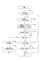
- FIG. 14 is a flowchart of the frame reception process.
- the frame reception process is started when the node device 100 is turned on.
- step S201 the receiving unit 101 waits until a frame is received. That is, if the receiving unit 101 has not received a frame, step S201 is repeated.
- the receiving unit 101 outputs the received frame to the frame branching processing unit 106, and the process proceeds to step S202.
- step S202 the frame branching processing unit 106 refers to the value of the type field of the frame received by the receiving unit 101 in step S201, and determines the frame type. If the received frame type is a hello frame, the process proceeds to step S203. If the received frame type is a data frame, the process proceeds to step S204. If the received frame type is an ACK frame, the process proceeds to step S206.
- step S203 the frame branch processing unit 106 outputs the received hello frame to the link management unit 108, and the link management unit 108 performs the hello frame reception process of FIG. Then, the process returns to step S201.
- the frame branch processing unit 106 outputs a hello frame, it does not wait for the end of the hello frame reception process. The process may move to step S201.
- step S204 the frame branching processing unit 106 stores the data frame received in step S201 in the buffer unit 109. That is, the frame branching processing unit 106 reserves a new entry area in the buffer unit 109, and stores the data frame received in step S201 in the secured area. Further, the frame branching processing unit 106 extracts and stores the GS and FID values from the data frame for the next step S205.
- step S205 the frame branch processing unit 106 instructs the data frame processing unit 110 to perform data frame reception processing.
- the frame branching processing unit 106 notifies the data frame processing unit 110 of the GS and FID values of the data frame stored in step S204.
- the data frame reception process is as shown in FIGS.
- the node device 100 is a type of device that can also be a GS
- the data frame reception processing is as shown in FIGS.
- the process returns to step S201.
- the process may proceed to step S201 without waiting for the end of the data frame reception process.
- step S206 the frame branch processing unit 106 outputs the received ACK frame to the ACK processing unit 107, and the ACK processing unit 107 performs the ACK frame reception process of FIG. Then, the process returns to step S201.
- the process may proceed to step S201 without waiting for the end of the ACK frame reception process.
- FIG. 15 is a flowchart of the hello frame reception process in step S203 of FIG. The process of FIG. 15 is started when a hello frame is output from the frame branch processing unit 106 to the link management unit 108.
- step S301 the link management unit 108 determines whether or not an entry having the same value as the LS of the received hello frame as the node ID exists in the adjacent node management table 103 (see FIG. 9). If an entry is found, the process proceeds to step S302. If no entry is found, the process proceeds to step S303.
- the “received hello frame” in the description of FIG. 15 is the hello frame received by the receiving unit 101 in step S201 of FIG. That is, the “received hello frame” in the description of FIG. 15 is a hello frame that is output from the frame branching processing unit 106 to the link management unit 108 in step S202 and triggered to start the processing of FIG.
- step S302 the link management unit 108 sets the current time as the last update time of the entry found in step S301. Then, the process of FIG. 15 ends.
- step S302 is executed in the node device N 2, in the adjacent node management table 103-N 2 as shown in FIG. 9, the value of the last update time field corresponding to the node ID of N 1 is TA 2,1 And updated.
- the node device N 2 can store “at the time TA 2,1 , the node device N 2 can recognize the node device N 1 as an adjacent node device”.
- step S301 if no entry is found in step S301, it means that a hello frame has been received from a new node device that has not been recognized as an adjacent node device until now. Therefore, in the subsequent steps S303 to S308, processing for registering the new node device as an adjacent node device is performed.
- step S ⁇ b> 303 the link management unit 108 adds a new entry to the adjacent node management table 103.
- step S304 the link management unit 108 sets the LS value of the received hello frame and the current time in the new entry added in step S303. For example, when the hello frame 312 of FIG. 7 is received for the first time, the node device N 2 sets N 3 which is the LS value of the hello frame 312 in the node ID field of the new entry, and the last update time field of the new entry Set the current time to.
- the link management unit 108 includes the weighting table 104-i (1 ⁇ i ⁇ M) that has not yet been focused on in the weighting tables 104-1 to 104-M (see FIGS. 10 and 11). ) Is determined. If all the weighting tables 104-1 to 104-M have already been focused on, the processing in FIG. 15 ends. If there is a weighting table 104-i that has not yet been focused on, the processing moves to step S306.
- step S306 the link management unit 108 pays attention to the next weighting table from among the weighting tables 104-1 to 104-M that have not been noticed yet.
- the weighting table 104-i is noted in step S306.
- step S307 the link management unit 108 adds a new entry to the weighting table 104-i of interest. Further, in step S308, the link management unit 108 sets the LS value, initial weight value, and current time of the received hello frame in the LD, weight, and last update time fields of the new entry added in step S307. Set each.
- the initial weight value is a constant arbitrarily determined according to the embodiment.
- the weight value is 0 or more and 1 or less, and 1 is a special value indicating that the LD cannot be selected. Therefore, the initial weight value is an arbitrary value between 0 and 1 Good. More specifically, the initial weight value may be 0.5, for example.
- the first entry of the weighting table 104-1-N 3 shown at the top of FIG. 11 may be created as follows (however, in that case, the first entry is the last update time of the entry, the last update time T a of the other two entries are set different values, not exactly the same as FIG. 11).
- Node device N 7 weighting table 104-1-N 3 associated with a GD already exists. However, the node device N 3 has not recognized the node device N 2 as an adjacent node device until now.
- the node device N 3 has received a hello frame from the node device N 2 for the first time.
- the weighting table 104-1-N 3 was noted in step S306.
- step S308 N 2 that is the LS value of the received hello frame is set in the LD field of the new entry, and 0.5 that is the initial weight value is set in the weight field of the new entry. After execution of step S308, the process returns to step S305.
- FIG. 16 is a flowchart of the hello frame transmission process. The process of FIG. 16 is executed by the hello frame generation unit 112 in parallel with the process of FIG. Specifically, when the node device 100 is powered on, the hello frame generation unit 112 starts the process of FIG.
- step S401 the hello frame generation unit 112 determines whether or not the current time is the scheduled transmission time. If the current time is the scheduled transmission time, the process proceeds to step S402. If the current time is not the scheduled transmission time, the process returns to step S401. That is, the hello frame generation unit 112 waits until the scheduled transmission time.
- the transmission time ⁇ T hello between the reference time T ref and the hello frame may be determined in advance.
- the hello frame generation unit 112 can refer to the current time T now based on MPU201 clock of Figure 4, for example.
- the hello frame generation unit 112 may determine that “the current time is the scheduled transmission time” only when Z in Expression (4) is an integer.
- Z (T ref ⁇ T now ) / ⁇ T hello (4)
- the reference time T ref may be a predetermined constant or the time when the node device 100 is turned on.
- the transmission interval ⁇ T hello can be appropriately determined according to the embodiment, and may be a relatively long time such as 10 seconds, for example.
- the hello frame generation unit 112 requests the FID generation unit 113 to generate a new FID, and the FID generation unit 113 generates a new FID.
- the FID may be a sequence number, and the FID generation unit 113 may be realized using a counter circuit.
- the FID generation unit 113 may be realized by the MPU 201 executing a program.
- the hello frame generation unit 112 further generates a hello frame using the FID generated by the FID generation unit 113.
- the hello frame 312 in FIG. 7 is generated as follows. That is, the FID generator 113-N 3 of the node device N 3, and generates a value of F b as a new FID. Then, the hello frame generation unit 112-N 3 of the node device N 3 generates a new hello frame 312.
- the hello frame generation unit 112-N 3 sets a predetermined value of 0xFFFFFF in the LD, sets N 3 which is its own node ID in the LS and GS, and sets a predetermined value of 0x000000 in the GD. Set the value. Further, the hello frame generation unit 112-N 3, in the hello frame 312, the FID sets the value F b generated by the FID generator 113-N 3, the type sets a predetermined value H.
- step S403 the hello frame generation unit 112 requests the transmission unit 102 to transmit the generated hello frame, and the transmission unit 102 transmits the hello frame. Send. Then, the process returns to step S401.
- Each aging process may be started, for example, in response to an interrupt signal from the timer IC 203 in FIG.
- FIG. 17 is a flowchart of the aging process of the adjacent node management table 103.
- the timer IC203 outputs an interrupt signal at predetermined intervals I a link management unit 108
- link management unit 108 the interrupt signal as a trigger may perform processing of FIG. 17 at a predetermined interval I a.
- step S501 the link management unit 108 pays attention to the first entry in the adjacent node management table 103 (see FIG. 9).
- the entry in the adjacent node management table 103 focused by the link management unit 108 is referred to as a “target entry”.
- step S503 If the difference between the current time and the last update time of the target entry is greater than or equal to a predetermined value Ga, the process proceeds to step S503. On the other hand, the current time, the difference between the last update time of the target entry, is less than the predetermined value G a, the process proceeds to step S505.
- step S503 the link management unit 108 deletes the entry having the same value as the node ID of the entry of interest as the LD from the weighting table 104. For example, interest entry, if a third entry of the adjacent node management table 103-N 3 in FIG. 9, the value of the node ID of the target entry is N 5. Accordingly, in step S503, the link management unit 108 deletes the entry whose LD value is N 5 from each of the weighting tables 104-1-N 3 to 104-MN 3 . For example, in step S503, the third entry in the weighting table 104-1-N 3 and the third entry in the weighting table 104-2-N 3 in FIG. 10 are deleted.
- step S ⁇ b> 504 the link management unit 108 deletes the target entry from the adjacent node management table 103. Then, the process proceeds to step S505.
- step S ⁇ b> 505 the link management unit 108 determines whether an entry that has not been noticed still remains in the adjacent node management table 103. If the link management unit 108 finishes paying attention to all entries in the adjacent node management table 103, the processing in FIG. On the other hand, if an entry not yet noticed by the link management unit 108 remains in the adjacent node management table 103, the process proceeds to step S506.
- step S506 the link management unit 108 pays attention to the next entry among the entries not yet noticed in the adjacent node management table 103. Then, the process returns to step S502.
- the node device 100 stops receiving the hello frame from the node device that has been recognized as the adjacent node device by the aging process of FIG. 17 described above, “the node device is no longer adjacent to the node device 100. It will be possible to recognize that there is no. That is, the process of FIG. 17 allows the node device 100 to appropriately manage the adjacent node device as a potential LD candidate following the change in the environment.
- the predetermined interval I a and the predetermined value G a are desirably determined as appropriate according to the embodiment in accordance with the ease of change of the environment.
- the same hello frame transmission interval ⁇ T hello is set for all node devices in the network, and the predetermined value G a which is the aging time of the adjacent node management table 103 is G a > ⁇ T hello is satisfied.
- FIG. 18 is a flowchart of the aging process of the weighting table 104.
- the timer IC203 outputs an interrupt signal at predetermined intervals I w to the data frame processing unit 110, the data frame processing unit 110 may perform the process in FIG. 18 at a predetermined interval I w interrupt signal as a trigger.
- step S601 the data frame processing unit 110 pays attention to the first weighting table 104-1 in the weighting table 104 (see FIGS. 10 and 11).
- the weighting table focused by the data frame processing unit 110 is represented by the reference numeral “104-i” (1 ⁇ i ⁇ M), and is referred to as “target table”.
- i 1.
- step S602 the data frame processing unit 110 pays attention to the first entry of the attention table 104-i.
- an entry that the data frame processing unit 110 pays attention to in the attention table is referred to as a “notice entry”.
- the data frame processing unit 110 in step S603 the current time, the difference between the last update time of the target entry, it is determined whether more than a predetermined value G w.
- G w I w , G w ⁇ I w , or G w > I w may be used.
- the current time, the difference between the last update time of the target entry is less than the predetermined value G w, the process proceeds to step S605.
- step S604 the data frame processing unit 110 deletes the target entry from the target table 104-i. Then, the process proceeds to step S605.
- step S605 the data frame processing unit 110 determines whether or not there is an entry that has not been noticed yet in the attention table 104-i. If the data frame processing unit 110 has finished paying attention to all entries in the attention table 104-i, the process proceeds to step S607. On the other hand, if an entry not yet noticed by the data frame processing unit 110 remains in the attention table 104-i, the process proceeds to step S606.
- step S606 the data frame processing unit 110 pays attention to the next entry among the entries not yet noticed in the attention table 104-i. Then, the process returns to step S603.
- step S607 the data frame processing unit 110 determines whether there is an entry in the attention table 104-i. As a result of repeating steps S603 to S606, when there are no more entries in the attention table 104-i, the process proceeds to step S608. On the other hand, if one or more entries exist in the attention table 104-i, the process proceeds to step S609.
- step S608 the data frame processing unit 110 deletes the attention table 104-i in which no entry exists. Then, the process proceeds to step S609.
- step S609 the data frame processing unit 110 determines whether or not a weighting table that has not been noticed remains in the weighting table 104. If the data frame processing unit 110 finishes paying attention to all the weighting tables 104-1 to 104-M, the processing in FIG. 18 ends. On the other hand, if the weighting table 104-j (1 ⁇ j ⁇ M) not yet noticed by the data frame processing unit 110 remains in the weighting table 104, the process proceeds to step S610.
- step S610 the data frame processing unit 110 pays attention to the next weighting table 104-j that has not been noticed in the weighting table 104 (that is, selects the weighting table 104-j as the attention table 104-i). Then, the process returns to step S602.
- the node device 100 does not fall into a situation in which “the effects of past failures are accumulated and any adjacent node device cannot be selected as an LD”.
- the data frame can be transmitted through the path ⁇ N 1 , N 2 , N 3 , N 4 , N 7 >, for example, by actually recovering from the failure. However, this route will not be selected as a result of autonomous distributed cooperation. However, if the aging process of FIG. 18 is performed, the path ⁇ N 1 , N 2 , N 3 , N 4 , N 7 > can be selected in the situation assumed above.
- FIG. 19 is a flowchart of the aging process of the FID management table 105.
- the timer IC203 outputs an interrupt signal at predetermined intervals I f to the data frame processing unit 110, the data frame processing unit 110 may perform processing of FIG. 19 at a predetermined interval I f the interrupt signal as a trigger.
- step S701 the data frame processing unit 110 pays attention to the first entry in the FID management table 105 (see FIGS. 12 and 13).
- the entry that the data frame processing unit 110 pays attention to is referred to as a “target entry”.
- the data frame processing unit 110 in step S702 the current time, the difference between the last update time of the target entry, it is determined whether more than a predetermined value G f.
- G f I f , G f ⁇ I f , or G f > I f may be used.
- the predetermined value G w is the aging time of the weighting table 104
- a predetermined value G f is the aging time of the FID management table 105
- G f ⁇ Gw is satisfied.
- step S703 the current time, the difference between the last update time of the target entry, equal to or greater than a predetermined value G f, the process proceeds to step S703.
- step S703 the data frame processing unit 110 deletes the entry of interest from the FID management table 105. Then, the process proceeds to step S704.
- step S ⁇ b> 704 the data frame processing unit 110 determines whether an entry that has not been noticed still remains in the FID management table 105. If the data frame processing unit 110 has finished paying attention to all entries in the FID management table 105, the processing in FIG. On the other hand, if an entry not yet noticed by the data frame processing unit 110 remains in the FID management table 105, the process proceeds to step S705.
- step S705 the data frame processing unit 110 pays attention to the next entry among the entries not yet noticed in the FID management table 105. Then, the process returns to step S702.
- the above aging process of FIG. 19 can prevent a situation such as “the number of entries in the FID management table 105 continues to increase and the storage area is exhausted”.
- the predetermined value G f is determined so as to be equal to or longer than the length of time predicted for the data frame to reach the GD from the GS in the worst case in which backtracking occurs many times. It may be. In general, larger the network, it is desirable to set larger the predetermined value G f.
- FIGS. 20 to 23 are flowcharts of the data frame reception process in step S205 of FIG.
- a data frame reception process when the node device 100 is not a GS but a relay node device will be described with reference to FIGS.
- the part of FIG. 23 is replaced with the process of FIG. 29 described later.
- the data frame processing unit 110 When instructed to perform the data frame reception processing from the frame branching processing unit 106 in step S205 of FIG. 14, the data frame processing unit 110 starts the processing of FIG. As described above, the instruction from the frame branch processing unit 106 is accompanied by notification of the GS and FID values of the received data frame.
- step S801 the data frame processing unit 110 determines whether the LD value of the received data frame is its own node ID. If the LD value of the received data frame is not the own node ID, the process proceeds to step S802. If the LD value of the received data frame is the own node ID, the process proceeds to step S803.
- the “received data frame” is received by the receiving unit 101 in step S201 in FIG. 14 and stored in the buffer unit 109 in step S204, and the trigger for starting the process in FIG. This is the data frame.
- the frame branching processing unit 106 instructs the data frame processing unit 110 to start the data frame reception processing
- the frame branching processing unit 106 notifies the data frame processing unit 110 of the GS and FID values of the received data frame. Therefore, the data frame processing unit 110 can find an entry including the received data frame by searching the buffer unit 109 using the notified GS and FID values as keys. Therefore, the data frame processing unit 110 can read the value of each field included in the header of the received data frame from the found entry.
- step S801 the data frame processing unit 110 first reads and stores the value of each field included in the header of the received data frame from the buffer unit 109 as described above. Then, the stored LD value (that is, the LD value of the received data frame) is compared with its own node ID.
- the own node ID which is the node ID of the node device 100 itself, is recorded in advance in, for example, the flash memory 205 of FIG. 4, so that the data frame processing unit 110 can refer to the own node ID.
- step S802 the data frame processing unit 110 discards the received data frame. That is, the data frame processing unit 110 deletes the entry of the buffer unit 109 found in step S801. Then, the data frame reception process ends.
- the data frame processing unit 110 determines whether the LD value of the received data frame is equal to the own node ID. If the LD value of the received data frame is equal to the own node ID, the data frame processing unit 110 generates an ACK frame and requests the transmission unit 102 to transmit the ACK frame in step S803. Then, the transmission unit 102 transmits an ACK frame.
- the data frame processing unit 110-N 3 of the node device N 3 when the node device N 3 receives the data frame 303 in FIG. 7, the data frame processing unit 110-N 3 of the node device N 3 generates the ACK frame 322 in FIG. 7 in step S803. Then, the transmission unit 102-N 3 transmits the ACK frame 322.
- the data frame processing unit 110-N 3 sets N 2 which is the LS value of the received data frame 303 to the LD of the ACK frame 322, and sets its own node ID (that is, the node of the node device N 3 itself) ID N 3 ) is set in LS of ACK frame 322. Further, since the ACK frame 322 is irrelevant except for the node device N 2 which is the LS of the corresponding data frame 303, the data frame processing unit 110-N 3 has a special value representing null in the GD of the ACK frame 322. Set 0x000000.
- the data frame processing unit 110-N 3 receives the ACK frame 322 so that the node device N 2 that has received the ACK frame 322 can recognize that the “ACK frame 322 is an ACK frame for the data frame 303”.
- Set GS and FID That is, the data frame processing unit 110-N 3 is the GS and FID of the ACK frame 322, respectively, to set the value N 1 and F a of GS and FID data frame 303 received.
- the data frame processing unit 110-N 3 sets a predetermined value A indicating “ACK frame” as the type of the ACK frame 322.
- the data frame processing unit 110-N 3 generates the ACK frame 322 as described above, and the transmission unit 102-N 3 transmits the ACK frame 322.
- step S804 the data frame processing unit 110 determines whether the GD value of the received data frame is the own node ID. If the GD value of the received data frame is the own node ID, the process proceeds to step S805. On the other hand, if the GD value of the received data frame is different from the own node ID, the process proceeds to step S806 in FIG.
- step S805 the data frame processing unit 110 passes the received data frame to the upper layer processing unit 111, and ends the data frame receiving process. Specifically, the data frame processing unit 110 outputs the entry of the buffer unit 109 found in step S801 to the upper layer processing unit 111 and deletes the entry from the buffer unit 109. Then, the data frame reception process ends.
- the node device N 7 receives the data frame from the node device N 6 at step S112 of FIG. 6, the received data frame is output to the upper layer processing section 111-N 7, the upper layer processing section 111-N 7 It is processed.
- the partial data including at least the payload necessary for the processing of the upper layer processing unit 111 is extracted from the entry of the buffer unit 109 found in step S801 and output to the upper layer processing unit 111 You may make it do.
- step S806 in FIG. 21 The processing after step S806 in FIG. 21 is executed when the LD value of the received data frame is equal to the own node ID and the GD value of the received data frame is different from the own node ID.
- step S806 the data frame processing unit 110 searches the FID management table 105 using the FID and GS values of the received data frame as search keys. As described above, the FID and GS values of the received data frame are notified from the frame branch processing unit 106 at the start of the processing of FIG.
- step S807 the data frame processing unit 110 determines whether or not the search result entry in step S806 has been hit. If the entry is hit, it means that the same data frame as the data frame that the node device 100 has transmitted before has been received, and therefore the process proceeds to step S808. On the other hand, if the entry is not hit, it means that a data frame that has not been transmitted by the node device 100 has been received, and the process moves to step S810.
- step S808 the data frame processing unit 110 takes out the LD and OLS values of the entry in the FID management table 105 hit in the search in step S806, and stores them in a storage area such as the DRAM 204 in FIG.
- step S809 the data frame processing unit 110 follows the weighting table (hereinafter referred to by the reference numeral “104-i” in the description of FIGS. 21 to 23) corresponding to the GD value of the received data frame. Update like this. That is, the data frame processing unit 110 changes the weight corresponding to the LD extracted in step S808 to the maximum value in the weighting table 104-i. In this embodiment, the maximum value of the weight is 1. After changing the weight, the process proceeds to step S817.
- the weighting table hereinafter referred to by the reference numeral “104-i” in the description of FIGS. 21 to 23
- the last update time in the entry of the FID management table 105 is set when the data frame is transmitted. Further, as described with reference to FIG. 19, the aging time Gf of the FID management table 105 is set to be equal to or longer than the time predicted in the worst case, for example. Therefore, when the data frame transmitted in the past by the node device 100 is received by the node device 100 through the network, it is guaranteed that the entry corresponding to the data frame still remains in the FID management table 105. .
- the weight is updated, and the weight is updated in each entry in the weighting tables 104-1 to 101-M. Sometimes the last update time is also set.
- (E1) A data frame in which the GD value is N GD , the GS value is N GS , the LD value is N LD , and the FID value is F c is transmitted from the node device 100.
- the last update time is set in the FID management table 105.
- the last update time T 103 is set in the entry E 3 in FIG. 12 in step S103.
- (E3) the value of GS is in N GS
- the value of FID is the same data frame F c, it is received by the node device 100.
- the node device N 3 in step S106 in FIG. 6 receives the data frame. Since there is no possibility that the value of GD of the data frame is rewritten when the relay, the value of GD of the data frame received by (E3), of course from the (E1), a N GD.
- the time point (E3) is before the time point (E5). Therefore, at the time of (E3), the existence of an entry whose LD field value is N LD is guaranteed in the weighting table 104-i corresponding to the node device N GD .
- time of step S106 is more particularly that at the time when the process of step S809 in the data frame reception processing triggered by the reception in step S106, the node device N 3 executes It is.
- step S809 the data frame processing unit 110 sets the weight value to the maximum value in the entry whose existence is guaranteed.
- step S810 the data frame processing unit 110 stores the LS value of the received data frame as an OLS in a storage area such as the DRAM 204 in FIG. .
- step S811 the data frame processing unit 110 searches the weighting table 104 using the GD value of the received data frame as a search key. Subsequently, in step S812, the data frame processing unit 110 determines whether the table is hit as a result of the search in step S811.
- step S812a If the weighting table corresponding to the GD value of the received data frame exists in the weighting table 104, the process proceeds to step S812a.
- the reference sign “104-i” introduced in step S809 indicates a weighting table corresponding to the GD value of the received data frame, and therefore, the table hit as a result of the search in step S811 is also “weighting table 104-”. i ".
- step S812a the data frame processing unit 110 adjusts the weighting table 104-i hit in the search in step S811.
- the weighting table adjustment process in step S812a is a process for neutralizing the side effects of the aging process as will be described in detail later with reference to FIG.
- step S812a it is guaranteed that entries corresponding to all adjacent node devices managed in the adjacent node management table 103 exist in the weighting table 104-i. Then, the process proceeds to step S817.
- step S813 the data frame processing unit 110 adds a new weighting table corresponding to the GD value of the received data frame. Note that the table added in step S813 is also the “weighting table 104-i”.
- step S814 the data frame processing unit 110 sets the GD value of the received data frame as the GD of the weighting table 104-i in the new weighting table 104-i.
- step S815 the data frame processing unit 110 creates as many new entries as the number of entries in the adjacent node management table 103 in the new weighting table 104-i.
- step S816 the data frame processing unit 110 sets the node ID, initial weight value, and current time of each entry in the adjacent node management table 103 in each entry created in step S815.
- a specific example of the above steps S811 to S816 is as follows. For example, when receiving the data frame 303 of FIG. 7 in step S102 in FIG. 6 from the node device N 2, the weighting table 104-N 3 of the node device N 3 are weighting table 104-1-N 3 in FIG. 11 Suppose that it did not exist. Then, the data frame processing unit 110-N 3 of the node device N 3 searches the weighting table 104-N 3 in step S811 using N 7 which is the GD value of the data frame 303 received by the node device N 3 as a search key. Even so, the table does not hit.
- the data frame processing unit 110-N 3 newly creates the weighting table 104-1-N 3 in step S813, and sets N 7 to the GD of the weighting table 104-1-N 3 in step S814.
- the data frame processing unit 110-N 3 creates the same number (ie, three) new entries as the adjacent node management table 103-N 3 in FIG. 9 in the weighting table 104-1-N 3 .
- the node ID of each entry of the adjacent node management table 103-N 3 is N 2 , N 4 and N 5 as shown in FIG. Therefore, in step S816, the data frame processing unit 110-N 3 sets N 2 , N 4, and N 5 as LDs in each of the three entries created in step S815. The data frame processing unit 110-N 3 sets an initial weight value of 0.5 in the weight fields of these three entries, and sets the current time in the last update time fields of these three entries. Set.
- Step S817 is executed after step S809 is executed, after step S816 is executed, or after it is determined in step S812 that the table is hit in the search of step S811. Therefore, when step S817 is executed, the existence of the weighting table 104-i corresponding to the GD value of the received data frame is guaranteed.
- step S817 the data frame processing unit 110, in the weighting table 104-i corresponding to the GD value of the received data frame, the LD value associated with the minimum weight among the LDs different from the OLS. To get.
- the data frame processing unit 110 selects, in the weighting table 104-i, the entry having the smallest weight value from the entries having as the LD a value different from the OLS value stored in step S808 or S810. Then, the data frame processing unit 110 stores the LD and weight values of the selected entry in a storage area such as the DRAM 204 in FIG.
- step S818 the data frame processing unit 110 determines whether one of the following two conditions (F1) and (F2) is satisfied.
- F1 The weight corresponding to the LD value acquired in step S817 (or S829 described later) is the maximum weight value (1.0 in this embodiment).
- step S830 If the condition (F1) or (F2) is satisfied, there is no longer any adjacent node device that can be selected as the LD, and the process moves to step S830 in FIG. On the other hand, if neither of the conditions (F1) and (F2) is satisfied, there is still an adjacent node device that can be selected as the LD. In other words, there is at least one adjacent node device that does not correspond to any of (G1) to (G4). Then, the node ID of the adjacent node device that can be selected as the LD is acquired in step S817 (or S829 described later).
- the adjacent node device Since it is determined that the path ahead from the adjacent node device is a dead path or a loop, the adjacent node device is associated with the maximum weight. (G2) Since the results of the failure to transmit data frames addressed to the same GD to the adjacent node device have accumulated in the past, the adjacent node device is associated with the maximum weight.
- step S818 The adjacent node device is OLS. Therefore, if it is determined in step S818 that neither of the conditions (F1) and (F2) is satisfied, the process proceeds to step S819.
- the processing after step S819 is processing for attempting to transfer the data frame to the adjacent node device identified by the acquired LD value.
- step S819 the data frame processing unit 110 creates a new data frame and outputs it to the transmission unit 102 as follows, and the transmission unit 102 transmits the created data frame.
- the data frame processing unit 110 designates the LD value acquired in step S817 (or S829 described later) as the LD of the new data frame, and designates its own node ID as the LS of the new data frame. .
- the data frame processing unit 110 copies the values of the GD, GS, FID, type, and length fields and the payload from the received data frame to a new data frame.
- the “received data frame” is a data frame stored in the entry in the buffer unit 109 found in step S801 as described above.
- step S821 the data frame processing unit 110 finds that the entry is hit in the search of the FID management table 105 in step S806, or adds a new entry to the FID management table 105 in steps S823 and S824 described later. Check whether the value has been added and set. That is, the data frame processing unit 110 confirms whether or not an entry having GS and FID having values equal to the GS and FID values of the received data frame exists in the FID management table 105.
- step S806 If the entry is hit in the search in step S806, or if a value is set by adding a new entry to the FID management table 105 in steps S823 and S824, the current data frame reception process has been executed in the past. This is a process triggered by reception of the same data frame as that transmitted by itself. Therefore, the data frame processing unit 110 subsequently executes step S822.
- the node device 100 receives for the first time. The first transfer of data frames is being attempted. Therefore, the process proceeds to step S823.
- step S822 the data frame processing unit 110 updates the entry hit in the search in step S806. Specifically, the data frame processing unit 110 sets the LD value of the data frame transmitted in step S819 in the LD field in the entry hit in the search in step S806, and sets the current value in the last update time field. Set the time. Then, the process proceeds to step S825.
- step S823 the data frame processing unit 110 adds a new entry to the FID management table 105.
- step S824 the data frame processing unit 110 sets a value for the new entry. Specifically, in the new entry, the data frame processing unit 110 copies the value of the data frame transmitted in step S819 to each field of FID, GS, and LD. In addition, in the new entry, the data frame processing unit 110 sets the current time in the last update time field, and copies the OLS value stored in step S810 in the OLS field. Then, the process proceeds to step S825.
- step S825 the data frame processing unit 110 waits for notification of the success or failure of transmission in step S819.
- the thread may sleep in step S825.
- the notification of “success in transmission” or “transmission failure” is a process for causing a thread.
- step S819 If the transmission in step S819 is successful, an ACK frame is returned from the adjacent node device designated as the LD in the data frame transmitted in step S819. Then, the ACK processing unit 107 performs the processing of FIG.
- the transmission failure in step S819 means that the node device 100 does not receive an ACK frame from the adjacent node device designated as LD in the data frame transmitted in step S819 even when the time T timeout in Expression (5) is reached. It is not received.
- the reception of the ACK frame is monitored by the processing of FIG. 26 described later by the ACK processing unit 107. If the ACK frame is not received even when the timeout time T timeout is reached, the ACK processing unit 107 notifies the data frame processing unit 110 of “ "Send failed".
- step S825 When the data frame processing unit 110 receives a “transmission success” or “transmission failure” notification from the ACK processing unit 107 after waiting in step S825, the process proceeds to step S826.
- step S826 based on the notification received from the ACK processing unit 107, the data frame processing unit 110 determines whether the transmission in step S819 is successful. If the transmission is successful, the process proceeds to step S827. If the transmission fails, the process proceeds to step S828.
- step S827 the data frame processing unit 110 decreases the weight corresponding to the pair of GD and LD of the data frame transmitted in step S819 in the weighting table 104.
- the GD of the data frame is not rewritten by the transfer.
- the data frame processing unit 110 performs weighting in the weighting table 104-i corresponding to the GD of the received data frame. Update.
- the data frame processing unit 110 searches the weighting table 104-i for an entry having the LD value acquired in step S817 (or step S829 described later) as an LD, and decreases the weight value of the found entry. Decreasing the weight value means increasing the priority of the corresponding LD.
- the data frame processing unit 110 may update the weight value of the found entry to, for example, W revised in Expression (6) in step S827.
- W revised max (W min , W current - ⁇ W success ) (6)
- step S827 the data frame processing unit 110 sets the current time as the last update time in the entry of the weighting table 104-i having the LD value acquired in step S817 (or step S829 described later) as the LD. Then, the data frame reception process ends.
- step S828 the data frame processing unit 110 increases the weight corresponding to the pair of GD and LD of the data frame transmitted in step S819 in the weighting table 104. That is, in step S828, the data frame processing unit 110 searches the weighting table 104-i for an entry having the LD value acquired in step S817 (or later-described step S829) as an LD, and increases the weight value of the found entry. To do. Increasing the weight value means lowering the priority of the corresponding LD.
- the data frame processing unit 110 may update the weight value of the found entry to W revised in Expression (7).
- W revised min (W max , W current + ⁇ W failure ) (7)
- step S828 the data frame processing unit 110 stores the LD value acquired in step S817 (or later-described step S829) as “LD failed in transfer” in a work area such as the DRAM 204 in FIG.
- the data frame processing unit 110 initializes the linear list on the DRAM 204 to be empty in step S817, and holds the LD value acquired in step S817 (or step S829 described later) each time step S828 is executed. May be added to the linear list.
- other data structures such as an array may be used for storing “LD failed to transfer”.
- step S828 the data frame processing unit 110 sets the current time as the last update time in the entry of the weighting table 104-i having the LD value acquired in step S817 (or step S829 described later) as the LD. Then, the process proceeds to step S829.
- step S829 the data frame processing unit 110 searches for other selectable adjacent node devices that have not been tried as LDs so far. Specifically, the data frame processing unit 110, in the weighting table 104-i corresponding to the GD value of the received data frame, is the smallest among the LDs other than the LD that failed to transfer and different from the OLS. The LD value associated with the weight is acquired. Note that the LD that failed to be transferred is stored in a work area such as the DRAM 204 in FIG. 4 in step S828, for example, in the form of a linear list.
- the data frame processing unit 110 selects the entry having the smallest weight value from the entries having the values (H1) and (H2) as LDs in the weighting table 104-i. Then, the data frame processing unit 110 stores the LD and weight values of the selected entry in a storage area such as the DRAM 204 in FIG.
- step S828 A value different from the LD value acquired in the previous step S817 or S829 (H2) A value different from the OLS value stored in the step S808 or S810 Therefore, for example, updated to 0.2 in step S828
- the adjacent node device associated with the weight is not selected as an LD in step S829, and an adjacent node device having a weight such as 0.8, which is greater than 0.2, may be selected in step S829.
- steps S817 to S829 are as follows.
- node devices N 3 , N 5 , and N 7 are adjacent to the node device N 4 in FIG.
- the value of the OLS of FID management table 105-N 4 entries E4 node device N 4 is N 3.
- step S817 since the data frame processing unit 110-N 4 of the node device N 4 first acquires the LD value N 7 in step S817, the data frame to the node device N 7 as in step S104. Transmission is performed. However, since the transmission in step S104 fails as shown in FIG. 6, the data frame processing unit 110-N 4 determines “transmission failure” in step S826.
- step S829 the LD value other than the LD that failed to transfer (ie, N 7 ) and different from the OLS (ie, N 3 ) is only N 5. It is. Therefore, the value N 5 of the LD in step S829 is acquired.
- step S829 When the LD value is acquired in step S829, the process returns from step S829 to step S818. Therefore, in the above example of the node device N 4, after step S829, it is executed steps S818 ⁇ S826 again. Then, as shown in FIG. 6 as step S105, it is determined that transmission is successful in step S826, step S827 is executed, and the data frame reception process ends.
- step S828 it will be as follows if the influence of updating a weight like Formula (7), for example with a specific example is demonstrated at step S828.
- the node device N 106 receives a first data frame specifying the node device N 118 as GD from the adjacent node device N 108 at time T rcv1 .
- the weighting table 104-g 106 -N 106 corresponding to the node device N 118 exists in the node device N 106 at time T rcv1 .
- the node device weight 0.4 to N 102 is, weight 0.7 to the node device N 103 is the weight 0 to the node device N 107 .1, is assumed that the weight 0.5 is associated with the node apparatus N 108 , respectively.
- step S817 the node device N 107 associated with the minimum weight 0.1 is selected as the LD.
- chance for reasons such as shield between the node device N 106 and N 107 are placed, temporarily, the wireless link of the node device N 106 and N 107 Suppose that communication is lost.
- step S829 the node device N 102 associated with the weight 0.4 is selected as the LD.
- the transmission of the data frame is successful in step S819, the ACK frame from the node device N 102 is returned.
- the weight of the node device N 102 in step S827 is updated from 0.4 to 0.3, the data frame reception process ends.
- the first data frame transmitted from the node device N 106 to the node device N 102 reaches the node device N 118 without backtracking to the node device N 106 . That is, in the weighting table 104-g 106 -N 106 , it is assumed that there is no entry whose weight is updated to 1 with the transfer of the first data frame.
- the weighting table 104-g 106 -N When the node device N 106 receives a second data frame from the node device N 103 at this time T rcv2 , which similarly designates the node device N 118 as GD, the weighting table 104-g 106 -N.
- the contents of 106 are as follows. That is, node device N 102 has weight 0.3, node device N 103 has weight 0.7, node device N 107 has weight 0.2, node device N 108 has weight 0.5, Each is associated.
- step S817 the node device N 107 still associated with the minimum weight is selected as the LD even though the transfer of the first data frame has failed. If the communication quality of the radio link between the node devices N 106 and N 107 is improved at time T rcv2 and the transmission of the second data frame in step S819 is successful, the node device N in step S827. The weight of 107 returns to 0.1 again.
- the weight of the node device N 107 remains 0.1. Therefore, when the node device N 106 receives a third data frame that similarly designates the node device N 118 as GD from the adjacent node device other than the node device N 107 at the subsequent time T rcv3 , the highest priority is given to the LD. The node device N 107 is still selected.
- the weighting table 104 does not react excessively to changes in the communication environment. Therefore, while the node device N 106 receives a plurality of data frames designating the same node device as the GD one after another, if the link in which the failure has occurred temporarily recovers from the failure, the environment will be improved. Thus, the past learning result is again utilized for the selection of the LD. In other words, in the above example, the node device N 107 that has been learned in the past when it is appropriate as the LD is again preferentially selected as the LD.
- the radio link between the node devices N 106 and N 107 has not recovered from the failure at the time T rcv2 .
- the node device N 107 having a weight of 0.2 is selected as the LD at the time of transmitting the second data frame.
- the weight of the node device N 107 is 0.3.
- the node device N 102 associated with the weight 0.3 may be selected as the LD, the transmission may be successful, and the weight may be updated to 0 and 2.
- the node device N 106 may receive the third data frame from the node device N 103 , the node device N 102 associated with the weight 0.2 is selected as the LD, and transmission is performed. Successful, node device N 102 may have a weight of 0.1. Then, for a while, the node device N 106 may continue to select the node device N 102 as the LD of the data frame designating the node device N 118 as GD.
- step S829 the LD is reselected.
- the node device N 107 that has been learned to be suitable as the LD before the time T rcv1 is associated with the weights 0.5 and 0.7 and is relatively unsuitable as the LD. than 108 and N 103, are preferentially selected as LD.
- the reason is that learning of the weights at the time of transmission of the first and second data frames changes the weights gently as shown in step S828, and the weight of the node device N 107 is still the node device N 108. This is because less than the weight of the or N 103.
- the weight is again reduced to 0.2 for the node device N 107 .
- the temporary environment change is not reflected excessively in the weighting table 104, so that past learning results are gradually reflected. Therefore, the probability that an appropriate LD is selected increases.
- the weight is slightly adjusted in step S828 so as not to be excessively affected by the temporary failure.
- step S818 If it is determined in step S818 that one of the two conditions (F1) and (F2) is satisfied, there is no longer an adjacent node device that can be selected as an LD, and the process proceeds to step S830 in FIG.
- step S830 the data frame processing unit 110 creates a new data frame as follows and outputs it to the transmission unit 102, and the transmission unit 102 transmits the created data frame.
- the data frame processing unit 110 designates the OLS value stored in step S808 or S810 in the LD of the new data frame, and designates its own node ID in the LS of the new data frame. In addition, the data frame processing unit 110 copies the values of the GD, GS, FID, type, and length fields and the payload from the received data frame to a new data frame.
- the “received data frame” is a data frame stored in the entry in the buffer unit 109 found in step S801 as described above.
- the transmission process performed in step S830 is a backtrack operation.
- step S830 A specific example of the transmission in step S830 is step S110 in FIG. After the transmission in step S830, the process proceeds to step S831.
- step S831 the data frame processing unit 110 searches the FID management table 105 using the FID and GS values of the received data frame as search keys.
- step S832 the data frame processing unit 110 determines whether the entry has been hit as a result of the search in step S831. If the entry is hit, the process proceeds to step S833. If the entry is not hit, the process proceeds to step S834.
- step S807 If it is determined in step S807 that “an entry has been hit”, the entry found as a result of the search in step S831 is the entry found as a result of the search in step S806. If it is determined in step S807 that “the entry has not been hit” and a new entry is created in step S823, the new entry created in step S823 is found as a result of the search in step S831.
- step S832 It is determined in step S832 that “the entry did not hit” in the cases (I1) and (I2), in other words, in the cases (J1) and (J2).
- step S807 it is determined that “the entry has not been hit”.
- step S818 Immediately after step S818 is executed for the first time, the process proceeds to step S830.
- step S833 the data frame processing unit 110 updates the entry hit as a result of the search in step S831. Specifically, in the hit entry, the data frame processing unit 110 copies the OLS value of the hit entry itself to the LD, and sets the current time as the last update time. Then, the process proceeds to step S836.
- step S834 the data frame processing unit 110 adds a new entry to the FID management table 105.
- step S835 the data frame processing unit 110 sets a value in the new entry added in step S834. Specifically, in the new entry, the data frame processing unit 110 copies the value of the received data frame to the FID and GS, sets the current time as the last update time, and sets the current time as the OLS and LD. The LS value of the received data frame is copied. Then, the process proceeds to step S836.
- step S836 the data frame processing unit 110 waits for a transmission success / failure notification regarding the data frame transmitted in step S830.
- the process proceeds to step S837. Since step S836 is similar to step S825, detailed description is omitted.
- step S837 the data frame processing unit 110 determines whether transmission of the data frame in step S830 is successful. If the transmission fails, the process proceeds to step S838. If the transmission is successful, the process proceeds to step S839.
- Step S838 is executed in exceptional cases (K1) and (K2).
- K1 All adjacent node devices other than OLS are (K1-1) or (K1-2).
- K1-1) Corresponds to the weight of the maximum value.
- K1-2 When a data frame is transmitted by designating as LD, transmission fails.
- K2 Transmission of the data frame to the OLS (that is, the backtrack operation) has failed.
- the data frame processing unit 110 discards the received data frame in step S838. That is, the data frame processing unit 110 deletes the entry found in step S801 from the buffer unit 109. Then, the data frame reception process ends.
- step S110 in FIG. 6 the node device N 3 which is the transmission performed at step S830.
- the node device N 2 returns an ACK frame to the node device N 3 in response to the transmission of the data frame from the node device N 3 to the node device N 2 in step S110.
- Step S830 the data frame transmitted by the node device N 3 in step S110 (that is, step S830) becomes the node device N. Assume that 2 was not reached. Then, since naturally the node device N 3 nor to receive an ACK frame from the node device N 2, the node device N 3 determines a "transmission failed" in step S837, executes Step S838. That is, the data frame to the node device N 1 is transmitted in step S101, before reaching the node device N 7 is a GD, disappear within network 1.
- the node device N 2 does not recognize that “when the node device N 7 is designated as the GD, it is inappropriate for the node device N 2 to select the node device N 3 as the LD”. That is, as in the example of FIG. 6, the node device N 2 is “when the node device N 7 is designated as GD, it is appropriate for the node device N 2 to select the node device N 6 as LD”. I can't learn.
- the node device N 2 receives another new data frame in which the node device N 7 is designated as the GD (or when the node device N 2 transmits the data frame as GS).
- the node device N 2 selects the node device N 3 as the LD.
- the node device N 2 can not receive the ACK frame, it is determined as "transmission failure" in step S826 of FIG. 22.
- the node device N 2 at step S828, corresponding to the node device N 2 in the weighting table 104-h 2 -N 2 corresponding to the node device N 7 is a GD (The reference numerals similar to the description of FIG. 6) Increase the weight to be used. Then, the node device N 2 is the next step S829, re-select a node device N 6 as LD.
- the weighting table 104-h 2 -N 2 at another node device N 2 is OLS relates discarded data frames Learning may be delayed.
- the node device N 2 can learn an appropriate weight through a series of processes triggered by the reception of the next data frame in which the node device N 7 is set to GD as in the previous data frame. That is, when viewed as an operation of the entire network 1 in which a plurality of data frames are circulated one after another, even if there is a node device whose weight learning is locally delayed due to a data frame transmission failure for backtracking to the OLS, The delay can be quickly recovered.
- Step S839 is executed when the data frame is successfully transmitted to the OLS.
- the data frame processing unit 110 decreases the weight corresponding to the combination of GD and LD of the data frame transmitted in step S830 in the weighting table 104.
- the data frame processing unit 110 updates the weight corresponding to the LD of the transmitted data frame (that is, the OLS stored in step S808 or S810) in the weighting table 104-i corresponding to the GD of the received data frame. To do.
- step S839 Details of step S839 are the same as step S827, and detailed description thereof is omitted.
- the data frame processing unit 110 may update the weight using, for example, equation (6). Further, the data frame processing unit 110 sets the current time as the last update time in the entry whose weight is updated in the weighting table 104-i. Then, the data frame reception process ends.
- weighting table adjustment process in step S812a of FIG. 21 will be described with reference to FIG. Note that the weighting table adjustment process of FIG. 24 is also called in step S1108a of FIG. 27 described later.
- “hit weighting table 104-i” means a table hit in the search in step S811 in FIG. 21 or the search in step S1107 in FIG.
- step S851 the data frame processing unit 110 pays attention to the first entry of the adjacent node management table 103 (see FIG. 9).
- a target entry an entry in the adjacent node management table 103 focused on by the data frame processing unit 110 is referred to as a “target entry”.
- step S852 the data frame processing unit 110 determines whether there is an entry including the value of the node ID of the entry of interest as LD in the hit weighting table 104-i. If there is an entry including the value of the node ID of the entry of interest as LD in the hit weighting table 104-i, the process proceeds to step S855. On the other hand, if there is no entry in the hit weighting table 104-i that includes the value of the node ID of the entry of interest as LD, the process proceeds to step S853.
- step S853 the data frame processing unit 110 adds a new entry to the hit weighting table 104-i.
- step S854 the data frame processing unit 110 sets a value for the new entry added to the weighting table 104-i in step S853. That is, in the new entry, the data frame processing unit 110 sets the node ID value of the entry of interest in the adjacent node management table 103 as the LD field, the initial weight value as the weight field, and the current time as the last update time field. To do.
- the initial weight value in step S854 is different from the initial weight value in step S308 in FIG. Specifically, the initial weight value in step S854 is the maximum value of weights less than 1 in the weight field of the hit weight table 104-i.
- the initial value in step S854 is 0.7.
- the initial weighting value in step S854 is an arbitrary value less than 1, for example, in step S308 in FIG. 0.5 may be used similarly to the initial weighting value.
- step S854 the learning result reflected in the existing entry of the weighting table 104-i is preferentially considered. As a result, the route does not fluctuate more than necessary, in other words, the route becomes stable.
- the initial weighting value in step S854 is 0. 0 as in step S308 in FIG.
- an adjacent node device in which no weight is learned that is, an adjacent node device in which the node ID is recorded as an LD in the new entry added in step S853 is greater than an adjacent node device having a weight of 0.7.
- the LD is preferentially selected. That is, the weight 0.7 as the accumulated learning so far is ignored.
- step S855 the data frame processing unit 110 determines whether or not there are entries that are not yet focused on in the adjacent node management table 103. If the data frame processing unit 110 has finished paying attention to all entries in the adjacent node management table 103, the processing in FIG. On the other hand, if an entry not yet noticed by the data frame processing unit 110 remains in the adjacent node management table 103, the process proceeds to step S856.
- step S856 the data frame processing unit 110 pays attention to the next entry among the entries not yet noticed in the adjacent node management table 103. Then, the process returns to step S852.
- the significance of the processing in FIG. 24 is as follows. As a side effect of the aging process for each entry in the weighting table 104-i, there is a possibility of the following situation immediately before the process of FIG. That is, there is a possibility that an entry having the node ID of an adjacent node device registered in the adjacent node management table 103 as LD does not exist in the weighting table 104-i.
- the adjacent node device of the node device 100 is a potential candidate for the LD selected by the data frame processing unit 110 when transmitting the data frame. Therefore, it is desirable for proper operation of the node device 100 to cover all adjacent node devices in the LD field of the hit weighting table 104-i.
- step S205 of FIG. 14 has been described in detail above with reference to FIGS.
- processing related to the notification of transmission success / failure in steps S826 and S837 of the data frame reception processing will be described with reference to FIG. 25 and FIG.
- FIG. 25 is a flowchart of the ACK frame reception process in step S206 of FIG. The processing in FIG. 25 is started when an ACK frame is output from the frame branching processing unit 106 to the ACK processing unit 107.
- step S901 the ACK processing unit 107 determines whether the LD value of the ACK frame received from the frame branching processing unit 106 is equal to the own node ID. If the LD value of the ACK frame is equal to the own node ID, the process proceeds to step S902. If the LD value of the ACK frame is different from the own node ID, the process of FIG. 25 ends.
- the ACK processing unit 107 can also refer to its own node ID stored in advance in the flash memory 205, for example.
- the irrelevant node device N 3 when the node device N 5 transmits an ACK frame for the data frame transmitted by the node device N 4 in step S105 in FIG. 6 as shown in step S105a in FIG. 30, the irrelevant node device N 3 also receives the ACK frame. To do. This is because the node device N 3 is adjacent to the node device N 5 .
- the node device N 3 since the ACK processing unit 107-N 3 of the node device N 3 immediately ends the processing of FIG. 25 as a result of the determination in step S901, the node device N 3 has a side effect due to the ACK frame unrelated to the node device N 3. Not receive.
- the ACK processing unit 107 specifies a transmitted data frame corresponding to the ACK frame from the GS and FID values of the ACK frame. For example, in response to the data frame 303 in FIG. 7 transmitted from the node device N 2 to the node device N 3 in step S102 in FIG. 6, the node device N 3 returns the ACK frame 322 in FIG. 7 to the node device N 2 .
- the ACK processing unit 107-N 2 of the node device N 2 performs the process of FIG. 25 in response to the reception of the ACK frame 322 will be described in detail as follows.
- step S902 the ACK processing unit 107-N 2 extracts GS and FID values (that is, N 1 and F a ) of the ACK frame 322. Further, since the buffer unit 109-N 2 has the same format as that in FIG. 8, the buffer unit 109-N 2 stores the data frame 303 that has been transmitted from the node device N 2 . Therefore, the ACK processing unit 107-N 2 searches the entry of the buffer unit 109-N 2 using the extracted GS and FID values (ie, N 1 and F a ) as keys, and identifies the entry including the data frame 303. To do.
- step S903 the ACK processing unit 107 makes the transmitted data frame identified in step S902 in a state where it can be deleted from the buffer unit 109. That is, the ACK processing unit 107 sets the entry found by the search in step S902 to a state where it can be deleted from the buffer unit 109. Thereafter, when a predetermined time elapses, the data frame corresponding to the ACK frame is deleted from the buffer unit 109.
- step S904 the ACK processing unit 107 notifies the data frame processing unit 110 of “successful transmission” regarding the transmitted data frame specified in step S902. Then, the process of FIG. 25 ends.
- the data frame processing unit 110 may be realized by the MPU 201 in FIG. 4 executing a program.
- the thread that causes the MPU 201 to function as the data frame processing unit 110 may sleep until the ACK frame is received after the data frame is transmitted.
- the notification of “successful transmission” in step S904 is a process for waking up a sleeping thread.
- the notification in step S904 is accompanied by notification of the GS and FID values of the data frame specified in step S902.
- the ACK processing unit 107-N 2 also notifies the data frame processing unit 110 of the GS and FID values (ie, N 1 and F a ) for identifying the data frame 303.
- FIG. 26 is a flowchart showing processing when an ACK frame is not received before the timeout time.
- the processing in FIG. 26 is periodically performed, for example, triggered by an interrupt signal generated by the timer IC 203 in FIG. 4 at a predetermined interval.
- step S1001 the ACK processing unit 107 pays attention to the first entry of the buffer unit 109 (see FIG. 8).
- the entry of the buffer unit 109 that the ACK processing unit 107 is paying attention to is referred to as a “target entry”.
- step S1002 the ACK processing unit 107 compares the current time with the value of the timeout time field of the entry of interest. If the current time is after the timeout time, the process proceeds to step S1003. On the other hand, if the current time has not yet reached the timeout time, the process proceeds to step S1005.
- step S1003 the ACK processing unit 107 notifies the data frame processing unit 110 of “transmission failure” regarding the data frame stored in the entry of interest in the buffer unit 109.
- the notification in step S1003 may be, for example, a process for waking up a sleeping thread, for example, similarly to the notification in step S904 in FIG.
- the notification in step S1003 is also accompanied by notification of the GS and FID values of the data frame.
- the ACK processing unit 107 reads the GS and FID values of the data frame stored in the entry of interest, identifies the data frame based on the read GS and FID values, and identifies “ “Transmission failure” is notified to the data frame processing unit 110.
- the data frame processing unit 110 may select an adjacent node device that has not been tried as an LD as a new LD and try to retransmit the data frame. Accordingly, the entry of interest is not deleted from the buffer unit 109 at the time of step S1003.
- step S1004 the ACK processing unit 107 sets the time T timeout of Expression (5) as the timeout time of the entry of interest. Then, the process proceeds to step S1005.
- step S1005 the ACK processing unit 107 determines whether or not an entry that has not been noticed still remains in the buffer unit 109. If the ACK processing unit 107 has finished paying attention to all entries in the buffer unit 109, the processing in FIG. On the other hand, if an entry not yet noticed by the ACK processing unit 107 remains in the buffer unit 109, the process proceeds to step S1006.
- step S1006 the ACK processing unit 107 pays attention to the next entry in the buffer unit 109 that has not been noticed yet. Then, the process returns to step S1002.
- the data frame reception processing described with reference to FIGS. 20 to 23 is an example in the case where the node device 100 is a node device of a type that does not become GS as described above. In the following, with reference to FIGS. 27 to 29, processing unique to a type of node device that can be a GS will be described.
- FIG. 27 and FIG. 28 are flowcharts of transmission processing when the node device 100 is GS and transmits a data frame. The process of FIG. 27 is triggered by a request from the upper layer processing unit 111 to the data frame processing unit 110.
- step S1101 the data frame processing unit 110 acquires the GD value and payload of the data frame from the upper layer processing unit 111 as a result of the upper layer protocol processing in the upper layer processing unit 111.
- the “upper layer protocol” may be an Ethernet protocol.
- the upper layer processing unit 111 outputs an Ethernet frame to the data frame processing unit 110 as a payload of the data frame defined in this embodiment.
- the upper layer processing unit 111 notifies the data frame processing unit 110 of the value set in the GD of the data frame in this embodiment.
- the data frame processing unit 110 creates a new data frame including the payload acquired from the upper layer processing unit 111, and sets the value acquired from the upper layer processing unit 111 in the GD of the generated data frame.
- the data frame processing unit 110-N 1 node device N 1 from the upper layer processing section 111-N 1 to N 7 was obtained as the value of GD, and N 7 to the GD of the data frame Set.
- step S1102 the data frame processing unit 110 obtains the length of the payload acquired in step S1101, and sets it in the length field of the created data frame.
- the data frame processing unit 110-N 1 node device N 1 since the length of the payload is P a, the data frame processing unit 110-N 1 node device N 1 was prepared It is set to P a length field of the data frame.
- step S1103 the data frame processing unit 110 sets its own node ID in the GS and LS of the created data frame.
- the data frame processing unit 110-N 1 of the node device N 1 sets N 1 to GS and LS of the created data frame.
- step S1104 the data frame processing unit 110 requests the FID generation unit 113 to generate a new FID. Then, since the FID generation unit 113 generates a new FID and outputs it to the data frame processing unit 110, the data frame processing unit 110 sets the generated FID in the FID field of the created data frame.
- step S1105 the data frame processing unit 110 sets a predetermined value D (see FIG. 7) indicating “data frame” in the type field of the created data frame. Note that the execution order of the above steps S1102 to S1105 is in no particular order.
- the data frame processing unit 110 stores the created data frame in the buffer unit 109 in step S1106. In other words, the data frame processing unit 110 secures a new entry area in the buffer unit 109 and stores the created data frame in the secured area. As shown in FIG. 8, the buffer unit 109 has a timeout time field, but at this time, the timeout time is not set.
- step S1107 the data frame processing unit 110 searches the weighting table 104 using the value of GD designated by the upper layer processing unit 111 in step S1101.
- step S1108 the data frame processing unit 110 determines whether the weighting table corresponding to the designated GD value has been hit as a result of the search in step S1107. If the weighting table corresponding to the designated GD value hits, the process proceeds to step S1108a. If the weighting table corresponding to the designated GD value does not exist, the process proceeds to step S1009.
- step S1108a the data frame processing unit 110 performs the weighting table adjustment process of FIG. 24 to neutralize the side effects of the aging process. Then, the process proceeds to step S1110.
- step S1109 the data frame processing unit 110 adds a new weighting table corresponding to the GD value designated in step S1101 to the weighting table 104. Specifically, the data frame processing unit 110 performs processing similar to steps S813 to S816 in FIG. 21 in step S1109.
- step S1109 the data frame processing unit 110 adds a new weighting table corresponding to the GD value designated by the upper layer processing unit 111, and the GD of the GD designated by the upper layer processing unit 111 in the new weighting table. Set the value as GD. Further, the data frame processing unit 110 creates the same number of new entries as the adjacent node management table 103 in the new weighting table. Then, the data frame processing unit 110 sets the node ID, the initial weight value, and the current time of each entry in the adjacent node management table 103 for each created entry.
- the weighting table corresponding to the value of GD designated in step S1101 is referred to by the reference numeral “104-i”. That is, the weighting table 104-i is a table that has been hit by the search in step S1107 or a table that has been added in step S1109.
- step S1108 After it is determined in step S1108 that the weighting table 104-i is hit or after the weighting table 104-i is created in step S1109, the process proceeds to step S1110.
- step S 1110 the data frame processing unit 110 acquires the LD value associated with the minimum weight in the weighting table 104-i corresponding to the GD value designated by the upper layer processing unit 111.
- a plurality of entries in the weighting table 104-i may have the same minimum weight.
- the data frame processing unit 110 selects and acquires any one of a plurality of LD values associated with the minimum weight in step S1110. If the OLS node ID is specified by the upper layer processing unit 111, the LD value excluding the OLS node ID is acquired.
- the data frame processing unit 110 stores the acquired LD value and the corresponding weight value in a storage area such as the DRAM 204 of FIG.
- step S1111 the data frame processing unit 110 determines whether any of the following two conditions (L1) to (L3) is satisfied.
- the weight corresponding to the LD value acquired in step S1110 is the maximum weight value (specifically, in this embodiment, 1.0).
- step S1112 If any of the conditions (L1) to (L3) is satisfied, there is no longer any adjacent node device that can be selected as the LD, and the process moves to step S1112. On the other hand, when neither of the conditions (L1) to (L3) is satisfied, there are still adjacent node devices that can be selected as the LD. In other words, there is at least one adjacent node device that does not correspond to any of (G1) to (G3) described for step S818 of the data frame reception process. Then, the node ID of the adjacent node device that can be selected as the LD is acquired in step S1110 (or step S1125 described later). Therefore, if it is determined in step S1111 that neither of the conditions (L1) and (L2) is satisfied, the process proceeds to step S1114.
- the data frame processing unit 110 discards the data frame in step S1112. That is, the data frame processing unit 110 deletes the entry newly created in step S1106 and storing the data frame from the buffer unit 109.
- step S1113 the data frame processing unit 110 notifies the upper layer processing unit 111 of “transmission failure”. That is, the data frame processing unit 110 notifies the upper layer processing unit 111 that the data frame has not been successfully transmitted to any adjacent node device. Then, the processes in FIGS. 27 to 28 are completed.
- step S1111 determines whether neither of the conditions (L1) and (L2) is satisfied. If it is determined in step S1111 that neither of the conditions (L1) and (L2) is satisfied, the process of trying to transfer the data frame to the adjacent node device identified by the acquired LD value is performed in step S1111. This is performed in S1114 to S1125.
- step S1114 the data frame processing unit 110 sets the LD value acquired in step S1110 or step S1125 described later to the LD of the data frame stored in the buffer unit 109 in step S1106. Then, the data frame processing unit 110 requests the transmission unit 102 to transmit a data frame in which the LD value is set. Then, the transmission part 102 transmits a data frame.
- step S1115 the data frame processing unit 110 sets the time T timeout of Expression (5) as the timeout time of the entry in the buffer unit 109 that stores the data frame in step S1106.
- step S1116 the data frame processing unit 110 searches the FID management table 105 using the own node ID and the FID generated by the FID generation unit 113 in step S1104.
- step S1117 the data frame processing unit 110 determines whether an entry has been hit in the search of the FID management table 105 in step S1116.
- step S1117 is executed for the first time, it is determined that “the entry has not been hit”, and when step S1117 is executed for the second time or later, it is determined that “the entry has been hit”.
- step S1116 If the entry is hit in the search in step S1116, the process proceeds to step S1118. On the other hand, if the entry is not hit in the search of step S1116, the process proceeds to step S1119.
- step S1118 the data frame processing unit 110 updates the entry hit in the search in step S1116. Specifically, the data frame processing unit 110 sets the LD value of the data frame transmitted in step S1114 in the LD field in the entry hit in the search in step S1116, and sets the current value in the last update time field. Set the time. Then, the process proceeds to step S1121.
- step S 1119 the data frame processing unit 110 adds a new entry to the FID management table 105.
- step S1120 the data frame processing unit 110 sets a value for the new entry. Specifically, in the new entry, the data frame processing unit 110 copies the value of the data frame transmitted in step S1114 to each field of FID, GS, and LD.
- the data frame processing unit 110 sets the current time in the last update time field, and the upper layer processing unit 111 specifies the OLS node ID in the OLS field. The designated node ID is set, and if the OLS node ID is not designated by the upper layer processing unit 111, the own node ID is copied.
- the node FID management table 105-N 1 entry E1 devices N 1 is for the data frame processing unit 110-N 1 node device N 1 created by the above processing.
- step S1121 the data frame processing unit 110 waits for notification of the success or failure of transmission in step S1114. Details of step S1121 are the same as step S825 of FIG.
- step S1121 the data frame processing unit 110 receives a notification of “transmission success” or “transmission failure” from the ACK processing unit 107 after waiting in step S1121, the process proceeds to step S1122.
- step S1122 the data frame processing unit 110 determines whether or not the transmission in step S1114 is successful based on the notification received from the ACK processing unit 107. If the transmission is successful, the process proceeds to step S1123. If the transmission fails, the process proceeds to step S1124.
- step S1123 the data frame processing unit 110 decreases the weight corresponding to the combination of GD and LD of the data frame transmitted in step S1114 in the weighting table 104.
- the data frame processing unit 110 uses the weight corresponding to the LD of the transmitted data frame in the weighting table 104-i corresponding to the value of GD designated from the higher layer processing unit 111, for example, using Equation (6). Update. Further, the data frame processing unit 110 sets the current time as the last update time in the entry whose weight is updated in the weighting table 104-i. Then, the processes in FIGS. 27 to 28 are completed.
- step S1124 the data frame processing unit 110 increases the weight corresponding to the combination of GD and LD of the data frame transmitted in step S1114 in the weighting table 104.
- the data frame processing unit 110 uses the weight corresponding to the LD of the transmitted data frame in the weighting table 104-i corresponding to the GD value designated by the upper layer processing unit 111, for example, using Equation (7). Update.
- step S 1124 the data frame processing unit 110 further stores the LD value of the transmitted data frame as “LD failed in transmission” in a work area such as the DRAM 204 in FIG. Similar to step S828 in FIG. 22, a data structure such as a linear list or an array may be used to store “LD failed to transmit”.
- step S1124 the data frame processing unit 110 further sets the current time as the last update time in the entry whose weight is updated in the weighting table 104-i. Then, the process proceeds to step S1125.
- step S1125 the data frame processing unit 110 searches for other selectable adjacent node devices that have not been tried as LDs so far. Specifically, the data frame processing unit 110 uses the minimum weight among the LDs other than the LD that failed to transmit in the weighting table 104-i corresponding to the GD value designated by the higher layer processing unit 111. The associated LD value is acquired.
- the LDs that failed to be transmitted are stored in a work area such as the DRAM 204 of FIG. 4 in step S1124, for example, in the form of a linear list or an array.
- the data frame processing unit 110 acquires, in the weighting table 104-i, an LD value that has not been acquired in step S1110 or S1125 in the past and that is associated with the minimum weight.
- the data frame processing unit 110 stores the acquired LD value and the corresponding weight value in a storage area such as the DRAM 204 of FIG. Then, the process returns to step S1111.
- FIG. 29 is a flowchart of a process performed by the node device 100 that can be a GS instead of the process of FIG. 23 as part of the data frame reception process.
- steps S801 to S829 in the data frame reception process are the same as when the node device 100 is a relay node device, and are shown in FIGS. It is as follows. However, if the node device 100 is a type of device that can also be a GS, when the data frame processing unit 110 determines in step S818 in FIG. 22 that “one of the conditions (F1) and (F2) is met”, The processing moves to step S830a in FIG.
- step S830a the data frame processing unit 110 determines whether or not the GS value of the received data frame is its own node ID. If the GS value of the received data frame is different from the own node ID, the process proceeds to step S830b. If the GS value of the received data frame is the own node ID, the process proceeds to step S830c.
- step S830b the data frame processing unit 110 creates a new data frame and outputs it to the transmission unit 102 as follows, and the transmission unit 102 transmits the created data frame.
- the data frame processing unit 110 designates the OLS value stored in step S808 or S810 in the LD of the new data frame, and designates its own node ID in the LS of the new data frame. In addition, the data frame processing unit 110 copies the values of the GD, GS, FID, type, and length fields and the payload from the received data frame to a new data frame. After transmitting the data frame, the process proceeds to step S831a.
- step S830c the data frame processing unit 110 notifies the upper layer processing unit 111 of “transmission failure”.
- the data frame processing unit 110 may extract partial data including a payload or a part of the payload necessary for processing of the upper layer processing unit 111 from the received data frame, for example, and output the partial data to the upper layer processing unit 111 .
- the upper layer processing unit 111 can recognize which data has failed to be transmitted based on the content of the data received from the data frame processing unit 110.
- the process proceeds to step S838a.
- step S831a the data frame processing unit 110 searches the FID management table 105 using the FID and GS values of the received data frame as search keys.
- the following steps S831a to S839a are similar to steps S831 to S839 in FIG. 23, respectively.
- step S832a the data frame processing unit 110 determines whether or not the entry is hit as a result of the search in step S831a. If the entry is hit, the process proceeds to step S833a. If the entry is not hit, the process proceeds to step S834a.
- step S807 If it is determined in step S807 that “an entry has been hit”, the entry found as a result of the search in step S831a is the entry found as a result of the search in step S806. If it is determined in step S807 that “the entry has not been hit” and a new entry is created in step S823, the new entry created in step S823 is found as a result of the search in step S831a.
- step S832a It is determined in step S832a that “the entry has not been hit” in the cases of (M1) and (M2).
- step S807 it was determined that “the entry did not hit”.
- step S818 Immediately after step S818 is executed for the first time, the process proceeds to step S830a.
- step S833a the data frame processing unit 110 updates the entry hit as a result of the search in step S831a. Specifically, in the hit entry, the data frame processing unit 110 copies the OLS value of the hit entry itself to the LD, and sets the current time as the last update time. Then, the process proceeds to step S836a.
- step S834a the data frame processing unit 110 adds a new entry to the FID management table 105.
- step S835a the data frame processing unit 110 sets a value in the new entry added in step S834a. Specifically, in the new entry, the data frame processing unit 110 copies the value of the received data frame to the FID and GS, sets the current time as the last update time, and sets the current time as the OLS and LD. The LS value of the received data frame is copied. Then, the process proceeds to step S836a.
- step S836a the data frame processing unit 110 waits for a transmission success / failure notification regarding the data frame transmitted in step S830b.
- the process proceeds to step S837a.
- step S837a the data frame processing unit 110 determines whether transmission of the data frame in step S830b is successful. If the transmission fails, the process proceeds to step S838a, and if the transmission is successful, the process proceeds to step S839a.
- Step S838a is executed in the case of (N1) or (N2).
- N1 The data frame transmitted by the node device 100 itself as GS is returned to the node device 100 by backtracking and received, and all the adjacent node devices of the node device 100 are (N1-1) or (N1-2).
- N1-1) Corresponds to the weight of the maximum value.
- N1-2 If a data frame is transmitted by designating as LD, transmission fails.
- the GS of the received data frame is a node device other than the node device 100, and all adjacent node devices other than the OLS are (N2-1) or (N2-2), and Transmission of the data frame to the OLS failed.
- N2-1 Corresponds to the maximum weight.
- N2-2 When a data frame is transmitted by designating as LD, transmission fails.
- the data frame processing unit 110 discards the received data frame in step S838a. That is, the data frame processing unit 110 deletes the entry found in step S801 from the buffer unit 109. Then, the data frame reception process ends.
- step S839a is executed when transmission from the node device 100 to the OLS of the node device 100 is successful for a data frame in which another node device that is not the node device 100 is GS.
- the data frame processing unit 110 decreases the weight corresponding to the pair of GD and LD of the data frame transmitted in step S830b in the weighting table 104.
- the data frame processing unit 110 updates the weight corresponding to the LD of the transmitted data frame (that is, the OLS stored in step S808 or S810) in the weighting table 104-i corresponding to the GD of the received data frame. To do.
- the data frame processing unit 110 may update the weight using Expression (6). Further, the data frame processing unit 110 sets the current time as the last update time in the entry whose weight is updated in the weighting table 104-i. Then, the data frame reception process ends.
- FIG. 30 is a timing chart showing the recognition of adjacent nodes by the transmission / reception of a hello frame and the route selection of FIG.
- each of the node devices N 1 to N 7 independently performs the hello frame transmission process of FIG. Which node is device is arbitrary to send a hello frame to the above, in the example of FIG. 30, first, the node device N 2 executes the step S403 of FIG. 16 in step S1201, transmits a hello frame. Then, the hello frame is received by the node devices N 1 , N 3 , and N 6 adjacent to the node device N 2 , respectively. Then, each of the node devices N 1 , N 3 , and N 6 calls and executes the hello frame reception process of FIG. 15 in step S203 of FIG. 14, and recognizes the node device N 2 as an adjacent node device.
- the node device N 4 executes the step S403 in FIG. 16, and transmits the hello frame. Then, the hello frame is received by the node devices N 3 , N 5 , and N 7 adjacent to the node device N 4 , respectively. Then, each of the node devices N 3 , N 5 , and N 7 calls and executes the hello frame reception process of FIG. 15 in step S203 of FIG. 14, and recognizes the node device N 4 as an adjacent node device.
- step S1203 the node device N 3 executes step S403 in FIG. 16, and transmits a hello frame 312 of FIG. Then, the hello frame 312 are respectively received by the node device N 2, N 4, and N 5 adjacent to the node device N 3. Then, each of the node devices N 2 , N 4 , and N 5 calls and executes the hello frame reception process of FIG. 15 in step S203 of FIG. 14, and recognizes the node device N 3 as an adjacent node device.
- step S1204 the node device N 7 executes the step S403 in FIG. 16, and transmits the hello frame.
- the link between the node device N 4 and N 7 is that a fault has not occurred yet. Therefore, the hello frame is received by the node devices N 4 and N 6 adjacent to the node device N 7 , respectively.
- each of the node devices N 4 and N 6 calls and executes the hello frame reception process of FIG. 15 in step S203 of FIG. 14, and recognizes the node device N 7 as an adjacent node device.
- step S1205 the node device N 1 executes the step S403 in FIG. 16, and transmits the hello frame. Then, the hello frame is received by the node device N 2 adjacent to the node device N 1 . Then, the node device N 2 calls and executes the hello frame reception process of FIG. 15 in step S203 of FIG. 14, and recognizes the node device N 1 as an adjacent node device.
- step S1206 the node device N 6 executes the step S403 in FIG. 16, and transmits the hello frame. Then, the hello frame is received by the node devices N 2 and N 7 adjacent to the node device N 6 , respectively. Then, the node devices N 2 and N 7 respectively call and execute the hello frame reception process of FIG. 15 in step S203 of FIG. 14, and recognize the node device N 6 as an adjacent node device.
- step S1207 the node device N 5 executes the step S403 in FIG. 16, and transmits the hello frame. Then, the hello frame is received by the node devices N 3 and N 4 adjacent to the node device N 5 , respectively. Then, the node devices N 3 and N 4 respectively call and execute the hello frame reception process of FIG. 15 in step S203 of FIG. 14, and recognize the node device N 5 as an adjacent node device.
- the node devices N 1 to N 7 in the network 1 shown in FIGS. 1 and 6 recognize the adjacent node devices, respectively, and store the adjacent node management tables 103-N 1 to 103-N 7 respectively . Update. Further, as shown in FIG. 15, the node devices N 1 to N 7 may update the weighting tables 104-N 1 to 104-N 7 ) in response to the reception of the hello frame.
- the node device N 1 in step S101 the data frame specifying a node device N 7 as GD, and it transmits the specified node device N 2 as LD.
- the node device N 1 in step S101 performs the processing of FIG. 27-28.
- the node device N 2 that has received the data frame calls and executes the processes of FIGS. 20 to 23 from step S 205 of FIG.
- Node device N 2 is able to send an ACK frame at step S803 in FIG. 20, is expressed as a step S101a in FIG. 30.
- the node device N 1 is waiting to receive an ACK frame at step S1121 in FIG. 28.
- the node device N 1 calls and executes the processing of FIG. 25 from step S206 of FIG. 14, and as a result, ends the standby of step S1121 and completes steps S1122 and S1123. To finish the process of FIG.
- the transmission in step S819 corresponds to step S102 in FIG.
- FIG. 7 illustrates the data frame 303 transmitted in step S102.
- the node device N 3 that has received the data frame calls and executes the processes of FIGS. 20 to 23 from step S 205 of FIG.
- Node device N 3 is able to transmit an ACK frame at step S803 in FIG. 20, is expressed as a step S102a in FIG. 30.
- FIG. 7 illustrates the ACK frame 322 transmitted in step S102a.
- the node device N 2 is waiting to receive an ACK frame at step S825 in FIG. 22.
- the node device N 2 calls and executes the processing in FIG. 25 from step S206 in FIG. 14, and as a result, ends the standby in step S825, and completes steps S826 and S827. To finish the process of FIG.
- the transmission in step S819 corresponds to step S103 in FIG.
- FIG. 7 illustrates the data frame 304 transmitted in step S103.
- the node device N 4 that has received the data frame calls and executes the processes of FIGS. 20 to 23 from step S 205 of FIG. Node apparatus N 4 in step S803 of FIG. 20 that transmits the ACK frame, and is represented as step S103a in FIG. 30.
- the node device N 3 is waiting to receive an ACK frame at step S825 in FIG. 22. Then, the node device N 3 receives the ACK frame transmitted in step S103a, invokes and executes the processing of FIG. 25 from step S206 in FIG. 14, as a result, after a wait in step S825, and step S826 S827 To finish the process of FIG.
- step S103a the node device N 4 that has transmitted the ACK frame in step S803 in FIG. 20 continues the processing from step S804, and in step S819 in FIG. 22, designates the node device N 7 as the LD. Send a data frame.
- the transmission in step S819 corresponds to step S104 in FIG.
- step S1208 the link between the node device N 4 and N 7 in step S1208 is failure, the data frame does not reach the node device N 7. Therefore, in FIG. 30, the arrow of step S104 is a broken line from the middle.
- Node device N 4 is waiting to receive an ACK frame at step S825 in FIG. 22. However, since the ACK frame is not received from the node device N 7 , the node device N 4 determines that transmission of the data frame to the node device N 7 has failed in step S1003 of the processing of FIG. recognize.
- step S819 transmits the data frame by specifying a node device N 5 as LD.
- the transmission in step S819 corresponds to step S105 in FIG.
- the node device N 5 that has received the data frame calls and executes the processing of FIGS. 20 to 23 from step S205 of FIG.
- Node device N 5 is able to send an ACK frame at step S803 in FIG. 20, is expressed as a step S105a in FIG. 30.
- the node device N 4 is waiting to receive an ACK frame at step S825 in FIG. 22.
- the node device N 4 calls and executes the processing in FIG. 25 from step S206 in FIG. 14, and as a result, finishes waiting in step S825, and steps S826 and S827. To finish the process of FIG.
- step S804 specifies the node device N 3 as LD Send a data frame.
- the transmission in step S819 corresponds to step S106 in FIG.
- the node device N 3 that has received the data frame calls and executes the processes of FIGS. 20 to 23 from step S 205 of FIG.
- Node device N 3 is able to transmit an ACK frame at step S803 in FIG. 20, is expressed as a step S106a in FIG. 30.
- the node device N 5 is waiting to receive an ACK frame at step S825 in FIG. 22. Then, the node device N 5 receives the ACK frame transmitted in step S 106 a, invokes and executes the processing of FIG. 25 from step S206 in FIG. 14, as a result, after a wait in step S825, and step S826 S827 To finish the process of FIG.
- the transmission in step S819 corresponds to step S107 in FIG.
- the node device N 5 that has received the data frame calls and executes the processing of FIGS. 20 to 23 from step S205 of FIG.
- Node device N 5 is able to send an ACK frame at step S803 in FIG. 20, is expressed as a step S107a in FIG. 30.
- the node device N 3 is waiting to receive an ACK frame at step S825 in FIG. 22. Then, the node device N 3 receives the ACK frame transmitted in step S107a, invokes and executes the processing of FIG. 25 from step S206 in FIG. 14, as a result, after a wait in step S825, and step S826 S827 To finish the process of FIG.
- step S804 the process proceeds to step S830 of FIG. 23 from step S818 in FIG. 22, the node device N 5 in step S830, transmits the data frame by specifying a node device N 4 is OLS as LD.
- the transmission in step S830 corresponds to step S108 in FIG.
- the node device N 4 that has received the data frame calls and executes the processes of FIGS. 20 to 23 from step S 205 of FIG. Node apparatus N 4 in step S803 of FIG. 20 that transmits the ACK frame, and is represented as step S108a in FIG. 30.
- the node device N 5 is waiting to receive an ACK frame at step S836 in FIG. 23. Then, the node device N 5 receives the ACK frame transmitted in step S108a, invokes and executes the processing of FIG. 25 from step S206 in FIG. 14, as a result, after a wait in step S836, and step S837 S839 To finish the process of FIG.
- step S830 of FIG. 23 from step S818 in FIG. 22, the node apparatus N 4 in step S830, transmits the data frame by specifying a node device N 3 is OLS as LD.
- the transmission in step S830 corresponds to step S109 in FIG.
- the node device N 3 that has received the data frame calls and executes the processes of FIGS. 20 to 23 from step S 205 of FIG.
- Node device N 3 is able to transmit an ACK frame at step S803 in FIG. 20, is expressed as a step S109a in FIG. 30.
- the node device N 4 is waiting to receive an ACK frame at step S836 in FIG. 23.
- the node device N 4 calls and executes the processing in FIG. 25 from step S206 in FIG. To finish the process of FIG.
- step S830 of FIG. 23 from step S818 in FIG. 22, the node device N 3 in step S830, transmits the data frame by specifying a node device N 2 is OLS as LD.
- the transmission in step S830 corresponds to step S110 in FIG.
- the node device N 2 that has received the data frame calls and executes the processes of FIGS. 20 to 23 from step S 205 of FIG.
- Node device N 2 is able to send an ACK frame at step S803 in FIG. 20, is expressed as a step S110a in FIG. 30.
- the node device N 3 is waiting to receive an ACK frame at step S836 in FIG. 23. Then, the node device N 3 receives the ACK frame transmitted in step S110a, invokes and executes the processing of FIG. 25 from step S206 in FIG. 14, as a result, after a wait in step S836, and step S837 S839 To finish the process of FIG.
- the transmission in step S819 corresponds to step S111 in FIG.
- the node device N 6 that has received the data frame calls and executes the processes of FIGS. 20 to 23 from step S205 of FIG.
- the fact that the node device N 6 transmits an ACK frame in step S803 in FIG. 20 is expressed as step S111a in FIG.
- the node device N 2 is waiting to receive an ACK frame at step S825 in FIG. 22.
- the node device N 2 calls and executes the processing in FIG. 25 from step S206 in FIG. 14, and as a result, finishes waiting in step S825, and steps S826 and S827 To finish the process of FIG.
- step S111a the node device N 6 that has transmitted the ACK frame in step S803 in FIG. 20 continues the processing from step S804, and in step S819 in FIG. 22, designates the node device N 7 as the LD. Send a data frame.
- the transmission in step S819 corresponds to step S112 in FIG.
- the node device N 7 that has received the data frame calls and executes the processes of FIGS. 20 to 23 from step S 205 of FIG.
- the fact that the node device N 7 transmits an ACK frame in step S803 in FIG. 20 is expressed as step S112a in FIG.
- step S1208 the route ⁇ N 1 , N 2 , N 6 , N 7 > is selected and learned. That is, the weighting tables 104-N 1 to 104-N 6 are updated in the node devices N 1 to N 6 by the series of processes described above.
- step S112a as a result of learning, the node device N 7 data frame specified as GD, instead of being trial and error transfer while backtracking in the network 1 as shown in FIG. 6, initially Is transferred efficiently.
- Some specific examples are as follows.
- the node device N 2 when the node device N 2 becomes GS and transmits a data frame designating the node device N 7 as GD, the node device N 2 is also based on the learned weighting table 104-N 2 . , it selects the node device N 6 from the beginning as LD. Then, the data frame is transmitted from the node device N 6 to the node device N 7 which is a GD.
- the node device N 5 uses the learned weighting table 104-N 5 to The node device N 4 is first selected as the LD, not the node device N 3 that has occurred. In the same manner, the node device N 4 selects the node device N 3 as LD, the node device N 3 Select a node device N 2 as LD, node device N 2 selects a node device N 6 as LD, node device N 6 selects a node device N 7 as LD.
- each node device autonomously searches for a route.
- the node device of the embodiment manages one or a plurality of candidate routes for each GD (final destination) using the weighting table 104 shown in FIG. Then, when receiving the frame to be transferred to the GD, the node device transfers the frame using the first candidate path. At this time, if the route of the first candidate is interrupted, the node device determines that the second candidate, the third candidate,. . . Transfer process using. Therefore, a high data arrival rate is realized.
- the quality may be temporarily degraded due to noise or fading, and the link may be disconnected.
- the link may be permanently interrupted.
- the network management apparatus periodically collects route information from all nodes, and creates a topology map based on the position and route information of each node. And a network management apparatus investigates the path
- the ping command and the traceroute command basically perform route investigation when each node device selects the first candidate route. That is, in the procedure using these commands, it is difficult to conduct a route investigation considering a detour route.
- FIG. 31 is a diagram illustrating a detour route using a fourth example of the network configuration.
- a network 4 in FIG. 1 is an example of an ad hoc network to which the present embodiment can be applied, and includes a plurality of node devices.
- the “node device” may be simply referred to as “node”.
- Each node device in the network 4 is assigned with a node ID indicated by a reference symbol in advance.
- nodes A to F, X, Y, and S have the function of the node device described with reference to FIGS.
- the node S is a server device or a gateway device having a function of managing a network.
- FIG. 31 (a) shows a topology map created by collecting route information from each node.
- the node F is connected to the node S.
- Nodes D, Y, and E are connected to the node F.
- One or a plurality of nodes may be provided between the nodes S and F, between the nodes F and D, between the nodes F and Y, and between the nodes F and E.
- Nodes D, E, and X are also connected to the node Y.
- Nodes A and B are connected to the node X.
- Node A is connected to node C, and node C is also connected to node B.
- the topology map for example, there are at least three paths between the nodes F and Y. For this reason, even if a failure occurs in one of the three paths between the nodes F and Y, communication can be continued using another path. On the other hand, there is only one path between the nodes Y and X at least on the topology map. Therefore, as shown in FIG. 31B, if the link between the nodes Y and X is disconnected, the nodes A to C and X cannot communicate with other nodes and are isolated. there's a possibility that.
- the topology map is created, for example, by collecting route information representing the first candidate route of each node. For this reason, this topology map does not necessarily represent all routes. In other words, there is a possibility that a detour path exists between the nodes D and X as shown in FIG. In this case, the nodes A to C and X can communicate with other nodes even if the link between the nodes Y and X is disconnected.
- a network administrator is required to avoid the occurrence of an isolated node as shown in FIG. 31 (b) in advance. For this reason, the network administrator investigates whether or not a bypass route exists for the route between the nodes Y and X, and if such a bypass route does not exist, measures such as adding a new node Will be carried out.
- the detour route investigation it is investigated whether or not a detour route exists for a desired route.
- the network administrator refers to the topology map as described above, extracts a route that may cause node isolation, and inputs an instruction to investigate whether there is a detour route for the route. To do. Then, the presence or absence of a detour route is determined by the detour route investigation method of the embodiment.
- the route state represented by the topology map may be different from the current route state.
- the route state represented by the topology map is different from the current route state due to a change in radio wave environment or the like. In this sense as well, it is important to investigate whether there is a detour route for the desired route.
- FIG. 32 is a diagram for explaining an outline of a method for investigating a detour route in the network 4.
- the network administrator inputs an instruction for investigating the detour route to the node device S.
- route YX it is investigated whether there is a detour route for the route between the nodes Y and X (hereinafter, route YX).
- the detour route investigation method of the embodiment is performed by the following procedure, for example.
- a solid line connecting the nodes represents a path detected by collecting path information, and is a broken line connecting the nodes (in FIG. 32, drawn between nodes D and A). ) Represents a route that was not detected by collecting route information.
- the network administrator refers to the topology map and extracts a route that may cause node isolation.
- this route may be referred to as a “survey target route”.
- the network administrator inputs to the node device S a detour route investigation instruction that designates a node far from the node device S among nodes at both ends of the investigation target route.
- a detour route investigation instruction designating the node X is input.
- the network administrator may designate the investigation target route (route YX in this example) instead of designating the node in the detour route investigation instruction.
- the node device S can detect a node farther from the node device S based on the positions of the node Y and the node X.
- the node device S operates as a survey requesting node device when a detour route survey instruction is input.
- the node device S will be referred to as “investigation request node device S”.
- the investigation request node device S transmits a frame requesting a detour route investigation to the node specified by the detour route investigation instruction.
- a frame requesting a detour route investigation is transmitted to the node X.
- the frame requesting the detour route investigation is expressed as a “survey request frame”.
- the investigation request frame is transmitted as one of the data frames described with reference to FIG.
- the node device X Upon receiving the survey request frame, the node device X operates as a survey execution node device.
- the node device X will be referred to as “survey execution node device X”.
- the investigation execution node device X detects the OLS (original transmission source adjacent node) of the investigation request frame.
- OLS means an adjacent node that transmits a frame when the node device first receives the frame.
- the investigation request frame is basically transmitted to the investigation execution node device X when each node device selects the first candidate route. Therefore, in the example shown in FIG. 32, the OLS of the investigation request frame is the node Y. Then, the investigation execution node device X stores the OLS of the investigation request frame.
- the survey execution node device X transmits a survey frame with the survey request node device S that first transmitted the survey request frame in the network 4 as the final destination.
- the investigation execution node device X transmits the investigation frame to the adjacent nodes other than the OLS of the investigation request frame among the adjacent nodes of the investigation execution node device X.
- the adjacent nodes of the investigation execution node device X are nodes Y, A, and B.
- the node Y is the OLS of the investigation request frame. Therefore, in this case, the investigation execution node device X transmits a frame for investigating the detour route to the node A and the node B with the investigation request node device S as the final destination.
- the frame for investigating this detour route is expressed as “survey frame” in the following description. Note that the survey frame is transmitted as, for example, one of the data frames described with reference to FIG.
- the investigation request node device S determines that there is a detour route with respect to the route YX. That is, as described above, the survey frame is transmitted from the survey execution node device X to an adjacent node other than the OLS of the survey request frame. In the example illustrated in FIG. 32, the survey frame is transmitted from the survey execution node device X to the nodes A and B without being transmitted to the node Y. Therefore, the investigation frame received by the investigation request node device S should have been transmitted from the investigation execution node device X via a route other than the route YX to reach the investigation request node device S.
- the investigation request node device S when it receives the investigation frame, it can determine that there is a detour route with respect to the route YX.
- the survey frame transmitted from the survey execution node device X reaches the survey requesting node device S via the node A and the node D. Thereafter, the investigation request node device S transmits a reception response frame corresponding to the investigation frame to the investigation execution node device X.
- the survey request node apparatus S fails to receive the survey frame within a predetermined time from when the survey request frame is transmitted, it determines that there is no detour route for the route YX. If it is determined that there is no detour route, the network administrator can consider installing a relay node for realizing the detour route.
- the investigation execution node device X determines that the transmission of the investigation frame to the investigation request node device S has been successful. That is, the investigation execution node device X determines that there is a detour route with the investigation request node device S.
- the investigation execution node device X When the investigation execution node device X cannot receive the reception response frame corresponding to the investigation frame from the investigation request node device S, it determines that transmission of the investigation frame to the investigation request node device S has failed. In this case, the investigation execution node device X determines that there is no detour route with the investigation request node device S.
- the investigation request node device S investigates the presence or absence of a detour route with the investigation execution node device X, and the investigation execution node device X also checks the investigation request node device S. It is possible to investigate whether there is a detour route between. That is, in the former case, the node device S performs a detour route investigation using the node device X as the investigation target node device. In the latter case, the node device X performs a detour route investigation using the node device S as the investigation target node device.
- a node device that generates and transmits a survey request frame is referred to as a “survey request node device”, and a node device that generates and transmits a survey frame according to the survey request frame It will be called an “execution node device”.
- the operations of the survey request node device and the survey execution node device described above are realized by, for example, the upper layer processing unit 111 illustrated in FIG.
- the upper layer processing unit 111 includes a request frame transmission unit 111a, a determination unit 111b, a response frame transmission unit 111c, a detection unit 111d, a survey frame transmission unit 111e, and a determination unit 111f in order to perform the above-described detour route inspection.
- the request frame transmission unit 111a, the determination unit 111b, the response frame transmission unit 111c, the detection unit 111d, the survey frame transmission unit 111e, and the determination unit 111f are realized, for example, by executing a software program.
- a part or all of the request frame transmission unit 111a, the determination unit 111b, the response frame transmission unit 111c, the detection unit 111d, the survey frame transmission unit 111e, and the determination unit 111f may be realized by a hardware circuit.
- the upper layer processing unit 111 includes a request frame transmission unit 111a and a determination unit 111b.
- the request frame transmission unit 111a makes an investigation requesting the investigation execution node device to transmit an investigation frame with the investigation execution node device (node device X in FIG. 32) as the final destination in response to an input from the network administrator.
- Send a request frame The investigation request frame is transmitted to the investigation execution node device to the adjacent node other than the transmission source adjacent node that relayed the investigation request frame among the adjacent nodes of the investigation execution node device. Request.
- the survey execution node device transmits the survey frame in response to the request.
- the determination unit 111b determines that there is a detour path with the investigation execution node device.
- the upper layer processing unit 111 may include a response frame transmission unit 111c.
- the response frame transmission unit 111c transmits a reception response frame to the investigation execution node device when receiving the investigation frame.
- the upper layer processing unit 111 includes a detection unit 111d, a survey frame transmission unit 111e, and a determination unit 111f.
- the detection unit 111d detects the transmission source adjacent node that relayed the first frame.
- the investigation frame transmission unit 111e transmits the second frame having the frame transmission source node device as the final destination to an adjacent node other than the transmission source adjacent node detected by the detection unit 111d.
- the determination unit 111f determines that there is no detour path with the frame transmission source node device when the transmission of the second frame fails.
- the first frame and the second frame correspond to a survey request frame and a survey frame, respectively.
- “second frame transmission failure” means that the second frame does not arrive at the frame transmission source node device in this example.
- the success / failure of transmission of the second frame is recognized based on, for example, the presence / absence of a response from the frame transmission source node device.
- the determination unit 111f determines that “no detour path exists between the frame transmission source node device” and the determination unit 111f, the higher layer processing unit 111 notifies the frame transmission source node device of the determination result. May be.
- the upper layer processing unit 111 may not include the detection unit 111d, the investigation frame transmission unit 111e, and the determination unit 111f.
- the upper layer processing unit 111 does not have to include the request frame transmission unit 111a, the determination unit 111b, and the response frame transmission unit 111c.
- each node device may be designated as a survey execution node device. Therefore, the upper layer processing unit 111 of each node device is not particularly limited, but preferably includes a detection unit 111d, a survey frame transmission unit 111e, and a determination unit 111f.
- the investigation request node device is realized by, for example, a node device that operates as a server device related to network management. Therefore, the request frame transmission unit 111a, the determination unit 111b, and the response frame transmission unit 111c may be provided only in the server device, for example.
- FIG. 33 is a flowchart showing the operation of the investigation request node device. This process is executed, for example, when a detour route investigation instruction is input by the network administrator. In this example, it is assumed that the detour route investigation instruction indicates the investigation execution node device.
- step S1401 the upper layer processing unit 111 initializes various variables related to the detour route investigation. For example, when a survey request frame is repeatedly transmitted a predetermined number of times until a response from the survey execution node device is obtained, a variable for counting the number of times the survey request frame is transmitted is initialized.
- step S1402 the request frame transmission unit 111a creates data (inspection request) indicating the detour route inspection request as a payload of the inspection request frame, designates the inspection execution node device as GD, and passes it to the data frame processing unit 110.
- the request frame transmission unit 111a starts timing of a timer that performs timeout monitoring of reception of a response frame with respect to the investigation request frame. Then, the node ID of the investigation execution node device and the timeout monitoring start time are associated with each other and stored in the investigation history table 112.
- Each node device receives a frame from an adjacent node and autonomously selects a route based on the header of the received frame and performs a transfer process as described with reference to FIGS. Thereby, the investigation request frame transmitted from the investigation request node device is transferred to the investigation execution node device designated as GD. Then, when receiving the investigation request frame, the investigation execution node device transmits the investigation frame with the investigation request node device as a GD, which will be described later with reference to FIG.
- the survey frame is one of the data frames and has a format shown in FIG.
- step S1403 the determination unit 111b waits for the occurrence of one of the above-described timer timeout and reception of a data frame from the investigation execution node device.
- the data frame from the survey execution node device is “GS” set in the header of the received frame is the survey execution node device, and “GD” set in the header of the received frame is the survey request. It represents a survey frame or a survey response frame transmitted from a survey execution node device that is a node device.
- the data frame receiving process of step S205 is executed in the flowchart shown in FIG. In the data frame receiving process, as shown in FIG.
- the received frame is converted into an upper layer processing unit by the process of step S805. 111.
- the determination unit 111b compares the GS set in the header of the received frame passed to the higher layer processing unit 111 with the node ID of the investigation execution node device stored in the investigation history table 112, so that the determination unit 111b The reception of the data frame from the execution node device is detected.
- the count period of the timer depends on the scale of the network, a sufficiently long period (for example, about 30 seconds) is set with respect to the time required for the frame to be transmitted to an arbitrary node. . If a timer timeout or reception of a data frame from the investigation execution node device is detected, the process proceeds to step S1403.
- step S1404 the determination unit 111b determines whether the data frame received from the investigation execution node device is detected in step S1403. If reception of a data frame from the investigation execution node device is detected in S1403, in step S1404, the determination unit 111b determines that reception of the data frame from the investigation execution node device is detected in step S1403. (S1404: Yes), the process proceeds to step S1405. On the other hand, when a timeout is detected in step S1403, the determination unit 111b determines that the data frame received from the investigation execution node device is not received in step S1403 (S1404: No), and the processing is performed in step S1408. Migrate to
- step S1405 the determination unit 111b of the upper layer processing unit 111 decodes the payload of the received frame.
- the determination unit 111b determines whether or not the received frame is an inspection frame based on whether or not the payload decoded in step S1405 is data (inspection) indicating an alternative route inspection.
- the determination unit 111b determines in step S1406 that the received frame is an inspection frame (step S1406: Yes), and the processing is performed. The process proceeds to step S1407.
- step S1407 the determination unit 111b determines that a detour route exists between the investigation execution node device. And the determination part 111b outputs the information showing that a detour route exists.
- step S1406 determines that the received frame is not an inspection frame (S1406: No), and processing Proceeds to step S1409.
- step S1409 the determination unit 111b determines whether or not the received frame is an investigation result frame based on whether or not the payload decoded in step S1405 is data (dead end) indicating that there is no detour path.
- step S1405 If the payload decoded in step S1405 is data (dead end) indicating that there is no detour path, in step S1409, the determination unit 111b determines that the received frame is an investigation result frame (step S1405). S1407: Yes), the process proceeds to step S1410.
- step S1405 If the payload decrypted in step S1405 is not data (dead end) indicating that there is no detour route, in step S1409, the determination unit 111b determines that the received frame is not a survey result frame (step S1405). S1409: No), the process returns to step S1403.
- step S1410 the determination unit 111b determines that there is no detour route between the investigation execution node device. And the determination part 111b outputs the information showing that a detour route does not exist, and the process of FIG. 33 is complete
- the determination result of the determination unit 111b is displayed on, for example, a survey request node device or a display device of a server computer connected to the survey request node. Or the determination result of the determination part 111b is stored in the memory
- the investigation execution node device stored in the investigation history table 112 to be compared with the GS of the received frame in step S1403 Node ID candidates can be narrowed down to those for which the detour route investigation result is undetermined.
- step S1408 the response frame transmission unit 111c creates data (abort) indicating an alternative route investigation end instruction as a payload of the reception response frame, designates the investigation execution node device as GD, and passes the data to the data frame processing unit 110. .
- the survey request node device transmits a survey request frame to the survey execution node device, and there is a detour path with the survey execution node device depending on whether or not the survey frame as a response can be received. Investigate whether or not to do so.
- the network administrator can easily know the presence or absence of a detour route with respect to a desired route (particularly, a route in which node isolation may occur due to disconnection of one link). Therefore, isolation of the node can be prevented beforehand.
- FIG. 34 is a flowchart showing the operation of the investigation execution node device. This process is executed, for example, when a frame is received from an adjacent node.
- step S1301 when the upper layer processing unit 111 receives a data frame, the upper layer processing unit 111 determines whether the received frame is a survey request frame. In this example, the investigation request frame is transmitted as a data frame as described with reference to FIG. Therefore, if the type of the received frame is “data”, the data frame receiving process in step S205 is executed in the flowchart shown in FIG. In the data frame reception process, as shown in FIG.
- step S805 is executed, and the received frame is passed to the upper layer processing unit 111. .
- the upper layer processing unit 111 decodes the payload of the received frame and checks whether or not the received frame is data (inspection request) indicating a bypass route inspection request, thereby determining whether or not the received frame is an inspection request frame. To check. If the upper layer processing unit 111 determines that the received frame is a survey request frame (S1301: Yes), the process proceeds to step S1302. On the other hand, when the upper layer processing unit 111 determines that the received frame is a survey request frame (S1301: Yes), the process of FIG. 34 ends.
- the detection unit 111d detects the OLS (original transmission source adjacent node) of the received investigation request frame.
- the OLS of the survey request frame represents an adjacent node that has transmitted the survey request frame when the survey request frame is first received. Further, the transmission source adjacent node of the received frame is identified by “LS” set in the header of the received frame.
- the detection unit 111d of the investigation execution node device X detects the node Y as the OLS of the investigation request frame. Then, the detection unit 111d stores the GS (node ID of the investigation request node device) set in the header of the investigation request frame and the OLS of the detected investigation request frame in the investigation table 112.
- the survey frame transmission unit 111e creates data (inspection) indicating a detour route survey as a payload of the survey frame, designates GD and OLS, and passes the data to the data frame processing unit 110.
- the final destination (GD) of this survey frame is the survey request node device that is the GS set in the survey request frame.
- the OLS is the OLS of the survey request frame stored in the survey history table 112 in step S1302.
- the investigation request node device transmits a reception response frame having the investigation request node device as the transmission source (GS) and the investigation execution node device as the final destination (GD).
- the reception response frame includes data representing a detour route investigation end instruction.
- step S1308 the survey frame transmission unit 111e waits for the occurrence of any of the following events: reception of a data frame from the survey requesting node device and notification of a survey frame transmission failure.
- the data frame from the survey request node device represents a reception response frame in which “GS” is the survey request node device and “GD” is the survey execution node device.
- the data frame receiving process of step S205 is executed in the flowchart shown in FIG. In the data frame receiving process, as shown in FIG. 20, if the GD of the received frame is itself (that is, the investigation requesting node device), the received frame is passed to the upper layer processing unit 111 by the process of step S805. .
- the determination unit 111b receives data from the investigation request node device. Detect frame reception.
- the notification of the investigation frame transmission failure means that the investigation frame transmission failure notified by the processing of step S1113 in the flowchart shown in FIG. 28 or step S830c in the flowchart shown in FIG. 29 when there is no detour path. Represents a notification.
- the process proceeds to step S1309.
- step S1309 the determination unit 111f checks whether the data frame from the investigation requesting node device is detected in step S1308.
- the determination unit 111f determines that the data frame from the investigation request node device is detected in step S1304 ( S1305: Yes), the process proceeds to step S1311.
- step S1311 the determination unit 111f decodes the payload of the received frame.
- step S1312 the determination unit 111f checks whether or not the received frame is a reception response frame depending on whether or not the payload decoded in step S1311 is data (abort) indicating an alternative route investigation end instruction.
- the determination unit 111f determines in step 1312 that the received frame is a reception response frame (step S1312: Yes). ), The process of FIG. 34 is terminated.
- the reception response frame is generated when the investigation frame arrives at the investigation request node device. That is, a path (link) between the investigation execution node device and the adjacent node device of the investigation execution node device that has transmitted the investigation request frame to the investigation execution node device between the investigation request node device and the investigation execution node device.
- a reception response frame is generated when there is a detour path to detour. Therefore, the determination unit 111f determines that there is a detour route when the reception response frame is received.
- step S1309 the determination unit 111f determines that the data frame from the investigation request node device is not detected in step S1308 (S1309). : No), the process proceeds to step S1313.
- step S1313 the determination unit 111f determines that there is no detour route between the investigation request node device. And the determination part 111f outputs the information showing that a detour route does not exist.
- step S1314 the determination unit 111f creates data (dead end) indicating that there is no detour route as the payload of the investigation result frame, specifies the GD, and passes the data to the data frame processing unit 110.
- the final destination (GD) of this survey frame is the survey request node device.
- a survey frame is created and transmitted according to the flowchart shown in FIG.
- the investigation result frame is transmitted when it is determined that there is no detour path.
- the node identified by the OLS when the investigation request frame is received is acquired as the LD.
- the node Y is acquired in step S1110, and the following survey frame having the format shown in FIG. 7 is created and transmitted.
- LD Y LS: X GD: S GS: X FID: a unique value (for example, sequence number) managed by the node device
- X Type D (data)
- Length Payload length
- Payload Data indicating that there is no detour (dead end)
- an example of recognizing as a survey result frame when the payload itself includes the character string “dead end” is described, but includes a specific numerical value or character indicating that no detour path exists. It may be an identification code.
- the determination unit 111f stores the determination result, the determination reason, and the time when the determination is performed in the investigation history table 112 in association with the node ID of the investigation requesting node device, or the investigation history table 112
- the node ID of this investigation requesting node device and the data stored in association with this node ID may be deleted.
- the investigation request node device receives the investigation result frame, between the investigation request node device and the investigation execution node device, an adjacent node device of the investigation execution node device that has transmitted the investigation request frame to the investigation execution node device; Recognize that there is no detour route that detours the route (link) to the investigation execution node device.
- the node device can transfer the investigation request frame and the reception response frame transmitted from the investigation request node device to the investigation execution node device by autonomously selecting a route. Further, the node device can transfer the investigation frame and the investigation result frame transmitted from the investigation execution node device to the investigation requesting node device by autonomously selecting a route.
- the investigation request node device when the investigation request node device receives the investigation frame, it transmits a reception response frame to the investigation execution node. Then, upon receiving this reception response frame, the investigation execution node device stops the process of transmitting the investigation frame.
- the detour route investigation method of the embodiment is not limited to this procedure. That is, the investigation execution node device may transmit the investigation frame to all adjacent nodes (except for the OLS of the investigation request frame) regardless of the reception response frame. In this case, it is possible to investigate whether there is a detour path for all adjacent nodes adjacent to the investigation execution node device. Further, the investigation request node device does not have to transmit the reception response frame when receiving the investigation frame. However, in this case, the investigation execution node device cannot recognize whether or not the investigation frame has arrived at the investigation request node device.
- the investigation execution node device transmits the investigation frames one by one to each adjacent node, but the detour route investigation method of the embodiment is not limited to this. That is, the survey execution node device may transmit the survey frame to two or more adjacent nodes at the same time. Alternatively, the survey execution node device may transmit the survey frame to all adjacent nodes (except for the OLS of the survey request frame) at the same time.
- the detour route investigation frame (survey request frame, investigation frame, reception response frame, investigation result frame) is realized as one form of the data frame shown in FIG.
- the detour route investigation method of the embodiment is not limited to this. That is, the detour route investigation frame may be realized by a dedicated frame to which a “type” different from the data frame shown in FIG. 7 is assigned.
- FIG. 36 is a diagram showing an investigation procedure when there is a detour route.
- routes SF, FD, FY, FE, DY, EY, YX, XA, XB, AC, and BC exist.
- communication between the nodes D and A is also possible.
- the node S is a survey requesting node device and the node X is a survey execution node device.
- a bypass route investigation request is transmitted from the investigation request node device S to the investigation execution node device X.
- the investigation execution node device X detects “node Y” as the OLS of the detour route investigation request.
- the survey execution node device X transmits a survey frame to an adjacent node other than the node Y with the survey requesting node device S as the final destination.
- the investigation execution node device X transmits the investigation node to the node A.
- the node device A When the node device A detects that the final destination of the investigation frame is not the node A but the node S, the node device A performs a frame transfer process. In this case, there is a possibility that the node C is selected as the transfer destination depending on the state of the weighting table 104 of the node apparatus A, but here, for simplicity of explanation, the node D is selected as the transfer destination. Shall. Then, the node device A transfers the investigation frame transmitted from the investigation execution node device X to the node D.
- the operation of the node device D and other node devices is basically the same as that of the node device A. Therefore, the investigation frame transmitted from the investigation execution node device X arrives at the investigation request node device S.
- the route YX is set between the investigation request node device S and the investigation execution node device X. It is determined that there is a detour route that does not include. Further, the survey requesting node device S transmits a survey end notification to the survey execution node device X using the reception response frame corresponding to the survey frame.
- the survey execution node device X receives the survey end notification corresponding to the survey frame. Thereby, the investigation execution node device X can also recognize that there is a detour route that does not include the route YX between the investigation request node device S and the investigation execution node device X. Then, the investigation execution node device X ends the detour route investigation. That is, thereafter, the survey frame is not transmitted.
- FIG. 37 is a diagram showing an investigation procedure when there is no detour route. Also in this embodiment, it is assumed that paths SF, FD, FY, FE, DY, EY, YX, XA, XB, AC, and BC exist. However, in this embodiment, it is assumed that no communication path exists between other nodes. 36, the detour route investigation request is transmitted from the investigation request node device S to the investigation execution node device X, and the investigation execution node device X transmits the investigation frame to an adjacent node other than the node Y. .
- the investigation execution node device X refers to the adjacent node management table 103 and selects the transmission destination of the investigation frame.
- the node Y is not selected as the transmission destination of the investigation frame because it is the OLS of the detour route investigation request. That is, the transmission destination of the investigation frame is the nodes A and B.
- the investigation frame transmission unit 111d of the investigation execution node device X first selects the node A. That is, the survey frame is transmitted to the node A.
- the node device A When the node device A detects that the final destination of the investigation frame is not the node A but the node S, as in the example shown in FIG. 36, the node device A performs a frame transfer process. Here, it is assumed that the node device A selects the node C as the transfer destination. Then, the node device A transfers the investigation frame transmitted from the investigation execution node device X to the node C.
- the operation of the node device C and the node device B is basically the same as that of the node device A. That is, the node device C transfers the investigation frame to the node device B, and the node device B transfers the investigation frame to the investigation execution node device X.
- the investigation execution node device X When the investigation execution node device X receives the investigation frame from the node device B, the investigation execution node device X selects the investigation frame transfer destination by executing the processing from step S801 shown in FIG. 20 to step S817 shown in FIG. Note that the weight of the node A is changed to the maximum value by the process of step S809 in the series of processes.
- nodes A, Y, and B are adjacent to the investigation execution node device X. Then, the investigation execution node device X selects the node B as the investigation frame transfer destination for the following reason.
- the node A is the LD when this investigation frame is first transmitted from the investigation execution node device X, and is recorded in the FID management table 105 of the investigation execution node device X. Therefore, the investigation execution node device X cannot transfer this investigation frame to the node A.
- the node Y is an OLS of the detour route investigation request transmitted from the investigation request node device S, and is excluded from the transmission destination of the investigation frame.
- the procedure for excluding the OLS of the detour route investigation request from the transmission destination of the investigation frame is, for example, specifying the OLS by the upper layer processing unit 111 in step S1303 of FIG. 34, and specifying this in S1110 of FIG. This is executed by obtaining an LD different from the OLS that has been performed.
- the upper layer processing unit 111 temporarily, for example, in the weighting management table 104 during the period during which the detour route investigation is performed (the period during which the process of the flowchart in FIG.
- the survey frame is transmitted from the survey execution node device X to the node B. Thereafter, this investigation frame returns to the investigation execution node device X again via the node C and the node A.
- the investigation execution node device X When the investigation execution node device X receives the investigation frame from the node device A, the investigation execution node device X searches the transfer destination of the investigation frame by executing again the processing from step S801 shown in FIG. 20 to step S817 shown in FIG. By the process of step S809 in the series of processes, the weight of the node B is changed to the maximum value. For this reason, at this point in time, there is no transfer destination of the investigation frame other than Y, which is the OLS of the investigation request frame, in the adjacent node management table 103. Therefore, “Yes” is determined in step S818 shown in FIG. Then, since the investigation execution node device X is the GS of this investigation frame, the flowchart shown in FIG. 29 is executed, and “Yes” is determined in step S830a. Accordingly, in step S830c, the data frame processing unit 110 notifies the upper layer processing unit 111 of “transmission failure”.
- the determination unit 111f of the investigation execution node device X determines “No” in step S1305 of FIG. As a result, the determination unit 111f determines in step S1306 that there is no detour route with the investigation request node device S.
- the investigation execution node device X notifies the investigation request node device S of the investigation result.
- the investigation execution node device X transmits the investigation result frame to the node Y with the investigation request node device S as the final destination.
- the investigation request node device S can recognize that there is no detour route. Note that the investigation request node device S can recognize that there is no detour route even when the investigation frame corresponding to the detour route investigation request cannot be received within a predetermined time.
- the investigation frame transmitted from the investigation execution node device X to the node A is transmitted to the investigation execution node device X via the nodes C and B in order.
- the survey execution node device X transmits a survey frame to the node A and also transmits a survey frame to the node B in the transfer procedure.
- the investigation frame transmitted from the investigation execution node device X to the node B returns to the investigation execution node device X via the nodes C and A in order. That is, the transmission to Node B has also failed.
- the investigation execution node device X may determine that “the transmission to the node A and the node B has failed” when one transfer procedure shown in FIG. 37 is executed. In this case, the determination unit 111f of the investigation execution node device X may determine that there is no detour route with the investigation request node S when one transfer procedure illustrated in FIG. 37 is executed. .
- the target communication node specified by the network administrator executes the detour route investigation in response to a request from the monitoring server. Thereby, it is investigated whether or not a detour path exists between the monitoring server and the target communication node. Therefore, the network administrator can immediately determine the risk of isolation for a desired communication node. When a communication node that is highly likely to be isolated is detected, the network administrator can prevent a communication failure by implementing a measure such as adding a communication node.
- the data frame transfer is performed without causing the data frame processing unit 110 to load the processing related to the bypass route survey.
- the data frame processing unit 110 may be configured to cause the data frame processing unit 110 to execute part or all of the processing related to the detour route investigation.
- a frame related to the detour route investigation may be transferred to the data frame processing unit 110 as a data frame.
- the data frame processing unit 110 selects an unprocessed received frame from the buffer unit 109, the data frame processing unit 110 refers to the frame type and identifies either the frame for the detour route investigation and the normal data frame. Can be preferentially selected and processed.
- the determination unit 111b or the determination unit 111f of the upper processing unit 111 can identify that the frame is related to the detour route investigation without decoding the payload.
Abstract
Description
ところが、アドホックネットワークでは、ネットワーク全体に渡って通信経路を正確に認識することは困難である。したがって、アドホックネットワークにおいては、各通信経路に対してそれぞれ迂回経路が存在しているか否かを確認することは容易ではない。 By the way, in general, it is preferable that the network has a bypass route (or a redundant route or an alternative route) in order to continue communication even when a failure occurs. In particular, in a wireless network, the link may be temporarily disconnected depending on the radio wave environment, and it is important to confirm in advance the presence or absence of a detour path. For this reason, conventionally, there has been proposed a technique for recovering a failure by distributed automatic detour routing when a link failure occurs in network communication composed of a plurality of node devices. (For example, Patent Document 2)
However, in an ad hoc network, it is difficult to accurately recognize a communication path over the entire network. Therefore, in an ad hoc network, it is not easy to check whether there is a bypass route for each communication route.
Destination)」という。なお、GDは、実施形態のネットワーク上でのフレーム伝送において、最終宛先ノードを表す。 By the way, as will be described in detail later with reference to FIG. 7, in the following, a PDU (Protocol Data Unit) that is a unit of data transmitted and received between node devices according to a communication procedure (protocol) and the data itself to be transmitted and received are referred to as “frame” Called. Data transmission / reception within the network 1 is performed using frames. The first transmission source node device in the network 1 is hereinafter referred to as a “GS (Global Source)”, and this transmission source node device. In the following, the destination node device of this frame set by (GS) is referred to as “GD (Global
Destination) ". Note that GD represents a final destination node in frame transmission on the network of the embodiment.
・ノード装置N105自身
・ノード装置N105に隣接する3つのノード装置N107、N111、およびN112
・ノード装置N105を3つの隣接ノード装置N107、N111、およびN112にそれぞれ接続する3本のリンク In FIG. 2, a portion recognized by the node device N 105 is represented by a solid line, and a portion that the node device N 105 does not need to recognize is represented by a broken line. That is, in FIG. 2, only the following items existing within the range of the hop number 1 as viewed from the node device N 105 are shown by solid lines.
Node device N 105 itself. Three node devices N 107 , N 111 , and N 112 adjacent to the node device N 105.
Three links connecting node device N 105 to three adjacent node devices N 107 , N 111 , and N 112 , respectively
ノード装置100は、フレームを受信する受信部101と、フレームを送信する送信部102を備える。また、ノード装置100は、フレームの送信のために用いる各種情報を格納するため、隣接ノード管理テーブル103、重み付けテーブル104、FID(Frame IDentification)管理テーブル105、及び、調査履歴テーブル112を備える。 FIG. 3 is a functional block diagram illustrating a configuration of the node device according to the embodiment. Specifically, each node device in FIG. 1 or FIG. 2 is, for example, the
The
受信部101がフレームを受信し、受信したフレームをフレーム分岐処理部106に出力する。すると、フレーム分岐処理部106がフレームの種別を判別する。 Each unit of the
The receiving
ここで、重み付けテーブル104は、フレームをどの隣接ノード装置に送信するかを決定するための情報をGDごとに管理するためのテーブルである。図3にはM個のGDそれぞれに対応して設けられた重み付けテーブル104-1~104-Mが示されている。本明細書において「重み付けテーブル104」とは、重み付けテーブル104-1~104-Mの総称である。また、ノード装置100の運用が開始される時点では、重み付けテーブル104は存在せず、M=0である。 In this embodiment, the
Here, the weighting table 104 is a table for managing, for each GD, information for determining which adjacent node device the frame is transmitted to. FIG. 3 shows weighting tables 104-1 to 104-M provided for each of the M GDs. In this specification, the “weighting table 104” is a general term for the weighting tables 104-1 to 104-M. In addition, when the operation of the
データフレーム処理部110は、受信部101が受信したデータフレームに対するACKフレームの送信を送信部102に依頼する。また、データフレーム処理部110は、受信されたデータフレームのGDの値がノード装置100の自ノードIDと等しいか否かを判断する。そして、受信されたデータフレームのGDの値がノード装置100の自ノードIDと異なる場合、データフレーム処理部110は、FID管理テーブル105を参照することにより、今回の受信が下記(A1)と(A2)のどちらに該当するのかを判断する。 An outline of the operation of the data
The data
データフレーム処理部110は、今回の受信が(A2)に該当すると判断すると、重み付けテーブル104を参照して、受信したデータフレームを転送するためにLDとして指定する隣接ノード装置を選択し、データフレームの転送を送信部102に依頼する。 (A2) A new data frame other than (A1) is received by the receiving
If the data
図4の例では、ノード装置100は、MPU(MicroProcessing Unit)201、PHY(PHYsical layer)チップ202、およびタイマIC(Integrated Circuit)203を備える。また、ノード装置100は、DRAM(Dynamic Random access Memory)204、フラッシュメモリ205、および無線モジュール206を備える。 FIG. 4 is a diagram illustrating a hardware configuration of the node device according to the embodiment. The
In the example of FIG. 4, the
・ノードβとαの間のリンクLβ,α
・ノードβとγの間のリンクLβ,γ
・ノードβとδの間のリンクLβ,δ
・ノードβとεの間のリンクLβ,ε
・ノードβとζの間のリンクLβ,ζ FIG. 5 is a diagram for explaining learning of weights by paying attention to one node device. In FIG. 5, six node devices in the
-Link L β, α between nodes β and α
Link L β, γ between nodes β and γ
Link L β, δ between nodes β and δ
Link L β, ε between nodes β and ε
Link L β, ζ between nodes β and ζ
あるとき、ノードβが、ネットワーク3内の不図示のあるノード(以下、便宜的に「ノードη」という)をGDとするデータフレーム301を、リンクLβ,αを介してノードαから受信する。ノードβは図3の重み付けテーブル104を有しており、このうちノードηに対応する重み付けテーブルを、図5の説明では便宜的に「104-h」という参照符号で参照する。 In the following, focusing on the node β in FIG. 5, the learning of the weight at the node β will be described.
At some point, the node β receives a
Wγ<Wδ<Wε<Wζ (1)
以下、この実施形態においては説明の便宜上、重みが0以上1以下の値をとり、重みの値が小さいほど当該重みに対応するノードの優先度が高いことを示すものとする。 For convenience of explanation, it is assumed that the weighting relationship at the time when the node β receives the
W γ <W δ <W ε <W ζ (1)
Hereinafter, in this embodiment, for convenience of explanation, the weight takes a value from 0 to 1, and the smaller the weight value, the higher the priority of the node corresponding to the weight.
ノードβがデータフレーム301をノードγに転送した時点で、偶然リンクLβ,γ、あるいは、ノードγに障害が発生していると、ノードβはノードγへの送信が失敗したと認識する。 (D1) In the case of a link failure When the node β transfers the
ノードβは、一旦、ノードγへのデータフレーム301の送信に成功する。例えば、ノードβは、データフレーム301に対するACKフレームをノードγから受け取ることで、ノードγへのデータフレーム301の送信が成功したことを認識する。よって、一旦ノードβは、LDとして選択したノードγに対応付けられた重みWγの値を小さくする。 (D2) When the
Wδ<Wε<Wζ<Wγ (2)
続いてノードβは、GDである不図示のノードηへデータフレーム301を到達させるため、不適切と判明したノードγ以外の隣接ノードをLDとして選択し、データフレーム301の再送信を試みる。具体的には式(2)に基づいて、ノードβは、現時点で最も軽い重みWδと対応付けられたノードδをLDとして選択し、ノードδにデータフレーム301を送信する。 Hereinafter, for convenience of explanation, it is assumed that the node β recognizes the transmission failure and sets the value of the weight W γ to the maximum value as in (D2) in the example of FIG. As a result, Expression (2) is established.
W δ <W ε <W ζ <W γ (2)
Subsequently, in order to make the
すると、ノードβは、ノードβ自身が過去にノードδに送信したデータフレーム301をノードζから受信するので、「ノードδへの送信は、ループの存在により失敗した」と認識することができる。認識の結果、ノードβは、「ノードηをGDとするデータフレームの送信時にノードδをLDとして選択することは不適切である」と学習し、重みWδの値を大きくする。 Subsequently, it is assumed that the
Then, since the node β receives from the node ζ the
Wε<Wζ<Wγ=Wδ (3)
図5には、ノードζから同一データフレーム301を受信して重み付けを更新した結果の新しい重み付けの関係として、式(3)を示してある。 Here, also when the node β receives the
Wε < Wζ < Wγ = Wδ (3)
FIG. 5 shows Expression (3) as a new weighting relationship as a result of updating the weighting by receiving the
ノード装置N2には、ステップS101で送信されたデータフレームのLSであるノード装置N1のほかに、ノード装置N3とN6が隣接している。そして、この2つの隣接ノード装置N3とN6のうちでノード装置N3の方が、重み付けテーブル104-h2-N2において、より軽い重みと対応付けられているとする。 In step S101, the node device N 1 is a GS, select the node device N 2 adjacent to only the node device N 1 as LD, and transmits the data frame to the node device N 2.
The node device N 2, in addition to the node device N 1 is an LS of the transmitted data frame at step S101, the node device N 3 and N 6 are adjacent. Of the two adjacent node devices N 3 and N 6 , the node device N 3 is associated with a lighter weight in the weighting table 104 -h 2 -N 2 .
そこで、ステップS106でノード装置N5は、ステップS105で受信したデータフレームを転送するためのLDとしてノード装置N3を選択し、ノード装置N3にデータフレームを送信する。 The node device N 5 is the other node device N 4 is LS of the transmitted data frame at step S105, only the node device N 3 are adjacent.
Therefore, the node device N 5 in step S106, select the node device N 3 as LD for transferring the received data frame at step S105, it transmits the data frame to the node device N 3.
そこで、ステップS112でノード装置N6は、ステップS111で受信したデータフレームを転送するためのLDとしてノード装置N7を選択し、ノード装置N7にデータフレームを送信する。 The node device N 6 are in the other node device N 2 is LS of the transmitted data frame step S111, only the node device N 7, which is also GD is adjacent.
Therefore, the node device N 6 at step S112, select the node device N 7 as LD for transferring the received data frame at step S111, it transmits the data frame to the node device N 7.
また、データフレームの転送において、局所的に不適切なノード装置がLDとして選択されても、最終的にはネットワーク全体としては、GSからGDに至る経路が選択される。なぜなら、各ノード装置がLDとして選択可能なノード装置を次々と選択し、選択可能なノード装置がなくなればバックトラック動作をするからである。 As described above, even if a failure occurs in the network 1, each node device behaves in an autonomous distributed manner, so that the data frame successfully reaches the GD.
In addition, even when a locally inappropriate node device is selected as the LD in the data frame transfer, the route from the GS to the GD is finally selected as the entire network. This is because each node device sequentially selects node devices that can be selected as LDs, and performs backtracking operations when there are no more node devices that can be selected.
ステップS110でのデータフレームの受信の結果、ノード装置N2は重み付けテーブル104-h2-N2の学習を行い、ノード装置N3に対応付けられた重みを最大値に設定している。したがって、ノード装置N2は、ノード装置N7をGDとする新たなデータフレームを隣接ノード装置N1から受信すると、最初からノード装置N6をLDとして選択する。つまり、ネットワーク1全体としては、自律分散的な学習の結果、バックトラックを含む試行錯誤なしに、データフレームを効率的に経路〈N1,N2,N6,N7〉によりGDまで送信することが可能となる。 The route selected in this way is learned and contributes to the efficiency of data frame transfer from the next time. The efficiency of learning will be described in detail as follows.
As a result of receiving the data frame in step S110, the node device N 2 learns the weighting table 104-h 2 -N 2 and sets the weight associated with the node device N 3 to the maximum value. Therefore, when the node device N 2 receives from the adjacent node device N 1 a new data frame having the node device N 7 as GD, the node device N 6 selects the node device N 6 as an LD from the beginning. That is, as a result of autonomous distributed learning, the entire network 1 efficiently transmits data frames to the GD through the path <N 1 , N 2 , N 6 , N 7 > without trial and error including backtracking. It becomes possible.
この実施形態におけるデータフレームは、図7のデータフレーム302のように、LD、LS、GD、GS、FID、タイプ、長さの各フィールドを含むヘッダと、ペイロードとを含む。例えば図5のデータフレーム301も、データフレーム302と同様の形式である。 Next, the configuration and operation of the
The data frame in this embodiment includes a header including fields of LD, LS, GD, GS, FID, type, and length, and a payload, as in the
しかし、もちろん実施形態によっては、データフレーム302のペイロードは、ネットワーク層(第3層)以上で定義されるプロトコルのPDUであってもよいし、特定の通信プロトコルとは無関係な生のデータであってもよい。例えば、データフレーム302のペイロードがIP(Internet Protocol)データグラムであってもよい。この場合、上位層処理部111はIPデータグラムを処理する処理部である。 Hereinafter, for convenience of explanation, it is assumed that the payload of the
However, of course, in some embodiments, the payload of the
データフレーム303は、図6のステップS102でノード装置N2がノード装置N3に送信するデータフレームである。データフレーム303の具体的な内容は以下のとおりである。 The format of the
The
・LSフィールドには、ステップS102の送信におけるLSであるノード装置N2のノードID(すなわちN2)が指定されている。 In the LD field, the node ID (that is, N 3 ) of the node device N 3 selected as the LD in the transmission in step S102 is designated.
In the LS field, the node ID (that is, N 2 ) of the node device N 2 that is the LS in the transmission in step S102 is designated.
・GSフィールドには、GSであるノード装置N1のノードID(すなわちN1)が指定されている。 In the GD field, the node ID (that is, N 7 ) of the node device N 7 specified by the node device N 1 that is the GS at the time of transmission in step S101 is specified.
In the GS field, the node ID (that is, N 1 ) of the node device N 1 that is the GS is specified.
・タイプフィールドには、「データフレーム」というタイプを示す所定の定数Dが指定されている。例えば、タイプは2ビットによって表すこともでき、D=(00)2でもよい。 · FID The field node device N 1 is a GS (and less F a) resulting FID is specified.
In the type field, a predetermined constant D indicating the type “data frame” is specified. For example, the type can be represented by 2 bits, and D = (00) 2 may be used.
・ペイロードとして、MAC層プロトコルのフレーム(例えばイーサネットフレーム)が含まれる。 · The length field, the length P a payload of the
The payload includes a MAC layer protocol frame (for example, an Ethernet frame).
また、この実施形態におけるハローフレームは、図7のハローフレーム311のように、LD、LS、GD、GS、FID、タイプの各フィールドを含むヘッダを有するが、ペイロードを持たない。ハローフレーム311の具体例はハローフレーム312であり、ハローフレーム312は後述の図30のステップS1203でノード装置N3により送信されるものである。 · GD, GS, FID, type, and each field length, the contents of the payload is the same as the
In addition, the hello frame in this embodiment has a header including LD, LS, GD, GS, FID, and type fields as in the
図8は、図3のバッファ部109に格納されるデータの例を示す図である。バッファ部109は、受信部101が受信した個々のデータフレームにそれぞれ対応する複数のエントリを含む。そして、各エントリは、タイムアウト時刻と受信したデータフレームを含む。 In the following, for simplification of description, when there is no possibility of confusion, for example, “LD field” may be simply referred to as “LD”. The same applies to the other fields.
FIG. 8 is a diagram illustrating an example of data stored in the
例えば、図6のステップS104でノード装置N7へのデータフレームの送信に失敗したノード装置N4は、ステップS105において、ノード装置N3から受信したデータフレームに対応するバッファ部109-N4内のタイムアウト時刻を更新する。更新後のタイムアウト時刻は、具体的には、ステップS105でノード装置N5に送信したデータフレームへのACKフレームの受信をいつまでノード装置N4が待つかを表す。 In detail, as shown in FIGS. 22, 26, and 28, the timeout time set in the
For example, the node device N 4 that has failed to transmit the data frame to the node device N 7 in step S104 of FIG. 6 is stored in the buffer 109-N 4 corresponding to the data frame received from the node device N 3 in step S105. Update the timeout time. Timeout timing of the updated, specifically, indicating whether the reception of the ACK frame to data frame sent to the node device N 5 in step S105 forever node device N 4 waits.
例えば、図1のネットワーク1では、ノード装置N2にはノード装置N1、N3、およびN6が隣接している。したがって、ノード装置N2の隣接ノード管理テーブル103-N2は、これら3つの隣接ノード装置N1、N3、およびN6にそれぞれ対応する3つのエントリがある。そして、隣接ノード装置Ni(i=1,3,6)に対応する各エントリにおいて、ノードIDフィールドには隣接ノード装置NiのノードIDであるNiが格納されており、最終更新時刻フィールドには、当該エントリが最後に更新された時刻TA2,iが格納されている。 FIG. 9 is a diagram illustrating an example of the adjacent node management table 103 in FIG. The adjacent node management table 103 has a node ID field and a last update time field.
For example, in the network 1 of FIG. 1, node devices N 1 , N 3 , and N 6 are adjacent to the node device N 2 . Therefore, the node adjacent node management table 103-N 2 of the apparatus N 2, these three adjacent node device N 1, N 3, and N 6 has three entries respectively corresponding to. In each entry corresponding to the adjacent node device N i (i = 1, 3, 6), are stored N i is the node ID of the adjacent node device N i is the node ID field, last update time field Stores the time TA 2, i when the entry was last updated.
図3に示すとおり、「重み付けテーブル104」とは、GDごとに管理される複数の重み付けテーブル104-1~104-Mの総称である。各重み付けテーブル104-i(1≦i≦M)は、対応するGDを記憶している。 FIG. 10 is a diagram illustrating an example of the weighting table 104 in FIG. FIG. 10 shows a weighting table 104-N 3 of the node device N 3 of FIG. 1 as a specific example.
As shown in FIG. 3, “weighting table 104” is a general term for a plurality of weighting tables 104-1 to 104-M managed for each GD. Each weighting table 104-i (1 ≦ i ≦ M) stores a corresponding GD.
・LDフィールドには、隣接ノード装置NiのノードIDであるNiが格納されている。 In the last update time field, the last update time TW 3, 7, i of the entry is stored.
In the LD field, N i that is the node ID of the adjacent node device N i is stored.
すなわち、重みW3,7,iは、ノード装置N7(つまり重み付けテーブル104-1-N3に対応するGD)をGDとして指定するデータフレームをノード装置N3が送信する場合に参照される、隣接ノード装置Niに対応する重みである。 · Weight the field, the weight W 3, 7 associated with the adjacent node device N i, i is stored.
That is, the weights W 3, 7, and i are referred to when the node device N 3 transmits a data frame designating the node device N 7 (that is, GD corresponding to the weighting table 104-1-N 3 ) as GD. is a weight corresponding to the adjacent node device N i.
・LDフィールドには、隣接ノード装置NiのノードIDであるNiが格納されている。 In the last update time field, the last update time TW 3, 4, i of the entry is stored.
In the LD field, N i that is the node ID of the adjacent node device N i is stored.
もちろん、重み付けテーブル104-N3には、さらに別のGDと対応づけられた重み付けテーブル104-j-N3(j>2)が含まれていてもよい。 · Weight the field, the weight W 3, 4 associated with the neighboring node device N i, i is stored.
Of course, the weighting table 104-N 3 may include a weighting table 104-jN 3 (j> 2) associated with another GD.
例えば、図6のステップS102でノード装置N2からデータフレームを受信した時点では、ノード装置N3の重み付けテーブル104-N3には、ノード装置N7に対応する重み付けテーブル104-1-N3が存在しなかったとする。そして、ステップS102の受信を契機として、以下のような内容の新たな重み付けテーブル104-1-N3が重み付けテーブル104-N3に作成されたとする。 FIG. 11 is a diagram for explaining changes in the weighting table 104-1-N 3 in FIG. In the example of FIG. 11, T a <T b <T c <T d <T e .
For example, in the time of receiving the data frame from the node device N 2 at step S102 of FIG. 6, the weighting table 104-N 3 of the node device N 3 is the weighting table 104-1-N 3 corresponding to the node device N 7 Is not present. Then, it is assumed that a new weighting table 104-1-N 3 having the following contents is created in the weighting table 104-N 3 with the reception of step S102.
・3つのエントリにおいて、隣接ノード装置Ni(i=2,4,5)に対応付けられる重みW3,7,iは、いずれも0.5である。 • Three of the last update time of entry is both time T a.
In all three entries, the weights W 3, 7, and i associated with the adjacent node devices N i (i = 2, 4, 5) are all 0.5.
そして、FID管理テーブル105の最終更新時刻フィールドには、エントリが最後に更新された時刻が格納される。 In the OLS field of the FID management table 105, the node ID of the adjacent node device designated in the LS field of the data frame when the data frame identified by the values of the FID field and the GS field is first received. Stored. The OLS field is also used to remove the OLS from the LD candidates when selecting the LD for data frame transfer, and is also used to determine the LD during the backtrack operation.
In the last update time field of the FID management table 105, the time when the entry was last updated is stored.
そして、ノード装置N1は、エントリE1のFIDフィールドとGSフィールドに、送信したデータフレームのFIDとGSの値を設定する。 When the node device N 1 transmits a data frame to the node device N 2 in step S101, the node device N 1 creates a new entry E 1 in the FID management table 105-N 1 .
Then, the node device N 1 sets the FID and GS values of the transmitted data frame in the FID field and GS field of the entry E 1 .
ところで、GSとFIDの値の組により一意に識別される、ある特定のデータフレームに関して、OLSとは、当該特定のデータフレームを最初に受信したときの当該特定のデータフレームのLSに指定されたノードIDで識別される隣接ノード装置のことである。 Also, the node device N 1 in step S101, the N 2 is a node ID of the node device N 2 selected as LD, it sets the LD field of the entry E 1.
By the way, regarding a specific data frame uniquely identified by a pair of GS and FID values, the OLS is designated as the LS of the specific data frame when the specific data frame is first received. An adjacent node device identified by a node ID.
図14は、フレーム受信処理のフローチャートである。フレーム受信処理は、ノード装置100に電源が入れられると開始される。 Next, details of the operation of the
FIG. 14 is a flowchart of the frame reception process. The frame reception process is started when the
そして、ステップS205でフレーム分岐処理部106は、データフレーム処理部110にデータフレーム受信処理を行うよう指示する。指示に際してフレーム分岐処理部106は、ステップS204で記憶しておいたデータフレームのGSとFIDの値をデータフレーム処理部110に通知する。 Although the
In step S205, the frame
例えば、ノード装置N2においてステップS302が実行された結果として、図9のように隣接ノード管理テーブル103-N2において、N1というノードIDに対応する最終更新時刻フィールドの値がTA2,1と更新される。その結果、ノード装置N2は「時刻TA2,1にはノード装置N2がノード装置N1を隣接ノード装置として認識可能な状況であった」と記憶しておくことができる。 In step S302, the
For example, as a result of step S302 is executed in the node device N 2, in the adjacent node management table 103-N 2 as shown in FIG. 9, the value of the last update time field corresponding to the node ID of N 1 is TA 2,1 And updated. As a result, the node device N 2 can store “at the time TA 2,1 , the node device N 2 can recognize the node device N 1 as an adjacent node device”.
そして、ステップS304でリンク管理部108は、ステップS303で追加した新規エントリに、受信したハローフレームのLSの値と現在時刻を設定する。例えば、図7のハローフレーム312を初めて受信したとき、ノード装置N2は、新規エントリのノードIDフィールドに、ハローフレーム312のLSの値であるN3を設定し、新規エントリの最終更新時刻フィールドに現在時刻を設定する。 In step S <b> 303, the
In step S304, the
さらに、ステップS308でリンク管理部108は、ステップS307で追加した新規エントリのLD、重み、最終更新時刻の各フィールドに、受信したハローフレームのLSの値と、初期重み付け値と、現在時刻を、それぞれ設定する。初期重み付け値は、実施形態に応じて任意に決められる定数である。 In step S307, the
Further, in step S308, the
・しかし、ノード装置N3は、ノード装置N2を隣接ノード装置として今まで認識していなかった。 Node device N 7 weighting table 104-1-N 3 associated with a GD already exists.
However, the node device N 3 has not recognized the node device N 2 as an adjacent node device until now.
・以上の状況において、ステップS306では重み付けテーブル104-1-N3が注目された。 The node device N 3 has received a hello frame from the node device N 2 for the first time.
In the above situation, the weighting table 104-1-N 3 was noted in step S306.
ステップS308の実行後、処理はステップS305に戻る。 Therefore, in step S308, N 2 that is the LS value of the received hello frame is set in the LD field of the new entry, and 0.5 that is the initial weight value is set in the weight field of the new entry.
After execution of step S308, the process returns to step S305.
Z=(Tref-Tnow)/ΔThello (4) For example, the transmission time ΔT hello between the reference time T ref and the hello frame may be determined in advance. Further, the hello
Z = (T ref −T now ) / ΔT hello (4)
例えば、図7のハローフレーム312は、次のようにして生成される。すなわち、ノード装置N3のFID生成部113-N3が、新たなFIDとしてFbという値を生成する。すると、ノード装置N3のハローフレーム生成部112-N3は、新たなハローフレーム312を生成する。 In step S402, the hello
For example, the
例えば、注目エントリが、図9の隣接ノード管理テーブル103-N3の3番目のエントリである場合、注目エントリのノードIDの値はN5である。したがって、ステップS503でリンク管理部108は、重み付けテーブル104-1-N3~104-M-N3のそれぞれから、LDの値がN5であるエントリを削除する。例えば、ステップS503では、図10の重み付けテーブル104-1-N3の3つ目のエントリと、重み付けテーブル104-2-N3の3つ目のエントリが削除される。 In step S503, the
For example, interest entry, if a third entry of the adjacent node management table 103-N 3 in FIG. 9, the value of the node ID of the target entry is N 5. Accordingly, in step S503, the
ステップS505でリンク管理部108は、まだ注目していないエントリが隣接ノード管理テーブル103に残っているか否かを判断する。リンク管理部108が、隣接ノード管理テーブル103のすべてのエントリに注目し終わっていれば、図17の処理は終了する。他方、まだリンク管理部108が注目していないエントリが隣接ノード管理テーブル103に残っていれば、処理はステップS506に移行する。 In step S <b> 504, the
In step S <b> 505, the
ステップS605でデータフレーム処理部110は、注目テーブル104-iにまだ注目していないエントリが残っているか否かを判断する。データフレーム処理部110が注目テーブル104-iのすべてのエントリに注目し終わっていれば、処理はステップS607に移行する。他方、まだデータフレーム処理部110が注目していないエントリが注目テーブル104-iに残っていれば、処理はステップS606に移行する。 In step S604, the data
In step S605, the data
ステップS609でデータフレーム処理部110は、まだ注目していない重み付けテーブルが重み付けテーブル104の中に残っているか否かを判断する。データフレーム処理部110が、すべての重み付けテーブル104-1~104-Mに注目し終わっていれば、図18の処理は終了する。他方、まだデータフレーム処理部110が注目していない重み付けテーブル104-j(1≦j≦M)が重み付けテーブル104の中に残っていれば、処理はステップS610に移行する。 In step S608, the data
In step S609, the data
そして、ステップS704でデータフレーム処理部110は、まだ注目していないエントリがFID管理テーブル105に残っているか否かを判断する。データフレーム処理部110がFID管理テーブル105のすべてのエントリに注目し終わっていれば、図19の処理は終了する。他方、まだデータフレーム処理部110が注目していないエントリがFID管理テーブル105に残っていれば、処理はステップS705に移行する。 In step S703, the data
In step S <b> 704, the data
なお、上記の所定の値Gfは、例えば、何度もバックトラックが生じる最悪ケースにおいてデータフレームがGSからGDに到達するのにかかると予測される時間の長さ以上になるよう、決められていてもよい。一般には、ネットワークの規模が大きいほど、所定の値Gfも大きく設定しておくことが望ましい。 The above aging process of FIG. 19 can prevent a situation such as “the number of entries in the FID management table 105 continues to increase and the storage area is exhausted”.
Note that the predetermined value G f is determined so as to be equal to or longer than the length of time predicted for the data frame to reach the GD from the GS in the worst case in which backtracking occurs many times. It may be. In general, larger the network, it is desirable to set larger the predetermined value G f.
(E1)GDの値がNGDで、GSの値がNGSで、LDの値がNLDで、FIDの値がFcのデータフレームがノード装置100から送信される。このとき、FID管理テーブル105において最終更新時刻が設定される。例えば、図6のノード装置N3において、ステップS103で図12のエントリE3に最終更新時刻T103が設定される。 Therefore, the following (E1) to (E5) are obtained in time series.
(E1) A data frame in which the GD value is N GD , the GS value is N GS , the LD value is N LD , and the FID value is F c is transmitted from the
(E5)上記(E2)の時点から、重み付けテーブル104のエージング時間Gwが経過する。 (E4) from the time of the (E1), aging time G f of FID management table 105 has elapsed.
(E5) from the time of the (E2), aging time G w of the weighting table 104 has elapsed.
続いて、ステップS812でデータフレーム処理部110は、ステップS811の検索の結果、テーブルがヒットしたか否かを判断する。 In step S811, the data
Subsequently, in step S812, the data
ステップS812aでデータフレーム処理部110は、ステップS811の検索でヒットした重み付けテーブル104-iを調整する。ステップS812aの重み付けテーブル調整処理は、詳しくは図24とともに後述するが、エージング処理の副作用を中和する処理である。 On the other hand, if the weighting table corresponding to the GD value of the received data frame does not exist in the weighting table 104, the process proceeds to step S813.
In step S812a, the data
例えば、図6のステップS102でノード装置N2から図7のデータフレーム303を受信したとき、ノード装置N3の重み付けテーブル104-N3には、図11の重み付けテーブル104-1-N3が存在しなかったとする。すると、ノード装置N3が受信したデータフレーム303のGDの値であるN7を検索キーにしてノード装置N3のデータフレーム処理部110-N3がステップS811で重み付けテーブル104-N3を検索しても、テーブルはヒットしない。 A specific example of the above steps S811 to S816 is as follows.
For example, when receiving the
ここで、具体例の説明から図21の処理一般の説明に戻る。ステップS817が実行されるのは、ステップS809の実行後、ステップS816の実行後、またはステップS811の検索においてテーブルがヒットしたとステップS812で判断された後である。よって、ステップS817の実行時には、受信したデータフレームのGDの値に対応する重み付けテーブル104-iの存在が保証されている。 As a result of the above steps S813 ~ S 816, the weighting table 104-1-N 3, such as the first stage of FIG. 11 is added in the weighting table 104-N 3.
Here, the description returns to the general processing of FIG. 21 from the description of the specific example. Step S817 is executed after step S809 is executed, after step S816 is executed, or after it is determined in step S812 that the table is hit in the search of step S811. Therefore, when step S817 is executed, the existence of the weighting table 104-i corresponding to the GD value of the received data frame is guaranteed.
(F1)ステップS817(または後述のS829)で取得したLDの値に対応する重みが、重みの最大値(この実施形態では1.0)である。 Subsequently, in step S818, the data
(F1) The weight corresponding to the LD value acquired in step S817 (or S829 described later) is the maximum weight value (1.0 in this embodiment).
他方、条件(F1)と(F2)のいずれも成立しない場合、まだLDとして選択可能な隣接ノード装置が残っている。換言すれば、(G1)~(G4)のいずれにも該当しない隣接ノード装置が、少なくとも1つは存在する。そして、LDとして選択可能な隣接ノード装置のノードIDが、ステップS817(または後述のS829)で取得されている。 If the condition (F1) or (F2) is satisfied, there is no longer any adjacent node device that can be selected as the LD, and the process moves to step S830 in FIG.
On the other hand, if neither of the conditions (F1) and (F2) is satisfied, there is still an adjacent node device that can be selected as the LD. In other words, there is at least one adjacent node device that does not correspond to any of (G1) to (G4). Then, the node ID of the adjacent node device that can be selected as the LD is acquired in step S817 (or S829 described later).
(G2)過去に当該隣接ノード装置への同一GD宛てのデータフレームの送信に失敗した結果が累積したため、当該隣接ノード装置は最大値の重みと対応付けられている。 (G1) Since it is determined that the path ahead from the adjacent node device is a dead path or a loop, the adjacent node device is associated with the maximum weight.
(G2) Since the results of the failure to transmit data frames addressed to the same GD to the adjacent node device have accumulated in the past, the adjacent node device is associated with the maximum weight.
そこで、ステップS818で条件(F1)と(F2)のいずれも成立しないと判断されると、処理はステップS819に移行する。ステップS819以降の処理は、取得済みのLDの値で識別される隣接ノード装置へのデータフレームの転送を試みる処理である。 (G4) The adjacent node device is OLS.
Therefore, if it is determined in step S818 that neither of the conditions (F1) and (F2) is satisfied, the process proceeds to step S819. The processing after step S819 is processing for attempting to transfer the data frame to the adjacent node device identified by the acquired LD value.
Ttimeout=Tnow+Twait (5)
なお、式(5)において時刻Tnowは現在時刻であり、時間TwaitはACKフレーム待ち時間である。 After the transmission in step S819, the process proceeds to step S820, and the data
T timeout = T now + T wait (5)
In Equation (5), time Tnow is the current time, and time Twait is the ACK frame waiting time.
そして、次のステップS824でデータフレーム処理部110は、新規エントリに値を設定する。具体的には、データフレーム処理部110は、新規エントリにおいて、FIDとGSとLDの各フィールドには、それぞれステップS819で送信したデータフレームの値をコピーする。また、データフレーム処理部110は、新規エントリにおいて、最終更新時刻フィールドには現在時刻を設定し、OLSフィールドには、ステップS810で記憶したOLSの値をコピーする。そして、処理はステップS825に移行する。 In step S823, the data
In step S824, the data
例えば、データフレーム処理部110が、所定のプログラムのスレッドを実行する図4のMPU201により実現される場合、ステップS825ではスレッドがスリープしてもよい。その場合、「送信成功」または「送信失敗」の通知は、スレッドを起こす処理である。 In step S825, the data
For example, when the data
Wrevised=max(Wmin,
Wcurrent-ΔWsuccess) (6)
なお、式(6)において、Wminは重みの最小値であり、この実施形態ではWmin=0である。また、ΔWsuccessは、送信が成功したときに重みを減らす所定の量であり、実施形態に応じて適宜値を決めることができる。例えば、ΔWsuccess=0.1でもよい。 Here, assuming that the current weight value of the found entry is W current , the data
W revised = max (W min ,
W current -ΔW success ) (6)
In Equation (6), W min is the minimum weight value, and in this embodiment, W min = 0. Further, ΔW success is a predetermined amount to reduce the weight when transmission is successful, and can be appropriately determined according to the embodiment. For example, ΔW success = 0.1 may be used.
Wrevised=min(Wmax,
Wcurrent+ΔWfailure) (7)
なお、式(7)において、Wmaxは重みの最大値であり、この実施形態ではWmax=1である。また、ΔWfailureは、送信が失敗したときに重みを増やす所定の量であり、実施形態に応じて適宜値を決めることができる。例えば、ΔWfailure=0.1でもよい。もちろん、ΔWfailure≠ΔWsuccessでもよい。 For example, in step S828, the data
W revised = min (W max ,
W current + ΔW failure ) (7)
In Equation (7), W max is the maximum weight value, and in this embodiment, W max = 1. Further, ΔW failure is a predetermined amount to increase the weight when transmission fails, and can be appropriately determined according to the embodiment. For example, ΔW failure = 0.1 may be used. Of course, ΔW failure ≠ ΔW success may be satisfied.
(H2)ステップS808またはS810で記憶したOLSの値とは異なる値
したがって、例えば、ステップS828で0.2に更新された重みと対応付けられた隣接ノード装置は、ステップS829でLDとして選択されず、ステップS829では0.2より大きな、0.8などの重みの隣接ノード装置が選択されることもありうる。 (H1) A value different from the LD value acquired in the previous step S817 or S829 (H2) A value different from the OLS value stored in the step S808 or S810 Therefore, for example, updated to 0.2 in step S828 The adjacent node device associated with the weight is not selected as an LD in step S829, and an adjacent node device having a weight such as 0.8, which is greater than 0.2, may be selected in step S829.
よって、上記のノード装置N4の例では、ステップS829の後、再度ステップS818~S826が実行される。そして、図6にステップS105として示すように、今度はステップS826で「送信成功」と判断され、ステップS827が実行されて、データフレーム受信処理が終了する。 When the LD value is acquired in step S829, the process returns from step S829 to step S818.
Therefore, in the above example of the node device N 4, after step S829, it is executed steps S818 ~ S826 again. Then, as shown in FIG. 6 as step S105, it is determined that transmission is successful in step S826, step S827 is executed, and the data frame reception process ends.
例えば、図2のネットワーク2において、ノード装置N106が隣接ノード装置N108から、ノード装置N118をGDとして指定する第1のデータフレームを時刻Trcv1に受信したとする。そして、時刻Trcv1にノード装置N106には、ノード装置N118に対応する重み付けテーブル104-g106-N106が存在したとする。また、時刻Trcv1の重み付けテーブル104-g106-N106においては、ノード装置N102には重み0.4が、ノード装置N103には重み0.7が、ノード装置N107には重み0.1が、ノード装置N108には重み0.5が、それぞれ対応付けられていたとする。 In addition, it will be as follows if the influence of updating a weight like Formula (7), for example with a specific example is demonstrated at step S828.
For example, in the network 2 of FIG. 2, it is assumed that the node device N 106 receives a first data frame specifying the node device N 118 as GD from the adjacent node device N 108 at time T rcv1 . Then, it is assumed that the weighting table 104-g 106 -N 106 corresponding to the node device N 118 exists in the node device N 106 at time T rcv1 . In the weighting table 104-g 106 -N 106 time T Rcv1, the node device weight 0.4 to N 102 is, weight 0.7 to the node device N 103 is the weight 0 to the node device N 107 .1, is assumed that the weight 0.5 is associated with the node apparatus N 108 , respectively.
ステップS830での送信後、処理はステップS831に移行する。ステップS831でデータフレーム処理部110は、受信したデータフレームのFIDとGSの値を検索キーとして用いてFID管理テーブル105を検索する。 A specific example of the transmission in step S830 is step S110 in FIG.
After the transmission in step S830, the process proceeds to step S831. In step S831, the data
(I1)ステップS807で「エントリがヒットしなかった」と判断された。
(I2)1回目にステップS818が実行された直後に、ステップS830に処理が移行した。 It is determined in step S832 that “the entry did not hit” in the cases (I1) and (I2), in other words, in the cases (J1) and (J2).
(I1) In step S807, it is determined that “the entry has not been hit”.
(I2) Immediately after step S818 is executed for the first time, the process proceeds to step S830.
(J2)受信したデータフレームのGSの値に対応する重み付けテーブル104-iでは、すべてのLDに最大値の重みが対応付けられている。 (J1) A data frame that has never been received by the
(J2) In the weighting table 104-i corresponding to the GS value of the received data frame, the maximum value weight is associated with all the LDs.
そして、次のステップS835でデータフレーム処理部110は、ステップS834で追加した新規エントリに値を設定する。具体的には、データフレーム処理部110は、新規エントリにおいて、FIDとGSには、受信したデータフレームの値をそれぞれコピーし、最終更新時刻には、現在時刻を設定し、OLSとLDには、受信したデータフレームのLSの値をコピーする。そして処理はステップS836に移行する。 On the other hand, in step S834, the data
In step S835, the data
(K1)OLS以外のすべての隣接ノード装置が、(K1-1)または(K1-2)である。
(K1-1)最大値の重みと対応付けられている。
(K1-2)LDとして指定してデータフレームを送信すると、送信に失敗する。
(K2)OLSへのデータフレームの送信(つまりバックトラック動作)は失敗した。 Step S838 is executed in exceptional cases (K1) and (K2).
(K1) All adjacent node devices other than OLS are (K1-1) or (K1-2).
(K1-1) Corresponds to the weight of the maximum value.
(K1-2) When a data frame is transmitted by designating as LD, transmission fails.
(K2) Transmission of the data frame to the OLS (that is, the backtrack operation) has failed.
例えば、図6のステップS110は、ノード装置N3がステップS830で行う送信である。図6の例では、ステップS110でのノード装置N3からノード装置N2へのデータフレームの送信に対して、ノード装置N2がACKフレームをノード装置N3に返信する。 In addition, it will be as follows if the influence of step S838 is demonstrated with a specific example.
For example, step S110 in FIG. 6, the node device N 3 which is the transmission performed at step S830. In the example of FIG. 6, the node device N 2 returns an ACK frame to the node device N 3 in response to the transmission of the data frame from the node device N 3 to the node device N 2 in step S110.
ステップS839でデータフレーム処理部110は、重み付けテーブル104において、ステップS830で送信したデータフレームのGDとLDの組に対応する重みを小さくする。換言すれば、データフレーム処理部110は、受信したデータフレームのGDに対応する重み付けテーブル104-iにおいて、送信したデータフレームのLD(つまりステップS808またはS810で記憶したOLS)に対応する重みを更新する。 Now, the description returns to the flowchart of FIG. Step S839 is executed when the data frame is successfully transmitted to the OLS.
In step S839, the data
続いてステップS854でデータフレーム処理部110は、ステップS853で重み付けテーブル104-iに追加した新規エントリに値を設定する。つまり、データフレーム処理部110は、新規エントリにおいて、隣接ノード管理テーブル103の注目エントリのノードIDの値をLDフィールドに、初期重み付け値を重みフィールドに、現在時刻を最終更新時刻フィールドに、それぞれ設定する。 In step S853, the data
In step S854, the data
重み付けテーブル104-iにおけるエントリごとのエージング処理の副作用として、図24の処理の直前には、次のような状況の可能性もある。すなわち、隣接ノード管理テーブル103に登録されているある隣接ノード装置のノードIDを、LDとして有するエントリが、重み付けテーブル104-iに存在しない可能性がある。 The significance of the processing in FIG. 24 is as follows.
As a side effect of the aging process for each entry in the weighting table 104-i, there is a possibility of the following situation immediately before the process of FIG. That is, there is a possibility that an entry having the node ID of an adjacent node device registered in the adjacent node management table 103 as LD does not exist in the weighting table 104-i.
例えば、図6のステップS102でノード装置N2がノード装置N3へ送信する図7のデータフレーム303に対して、ノード装置N3は図7のACKフレーム322をノード装置N2に返信する。ここで、ACKフレーム322の受信を契機にノード装置N2のACK処理部107-N2が図25の処理を行う場合について詳しく説明すると、以下のとおりである。 In step S902, the
For example, in response to the
ところで、図20~図23を参照して説明したデータフレーム受信処理は、上記のとおり、ノード装置100がGSとならないタイプのノード装置である場合の例である。以下では、図27~図29を参照して、GSとなりうるタイプのノード装置に特有の処理について説明する。 In step S1006, the
Incidentally, the data frame reception processing described with reference to FIGS. 20 to 23 is an example in the case where the
そしてステップS1108でデータフレーム処理部110は、指定されたGDの値に対応する重み付けテーブルが、ステップS1107の検索の結果としてヒットしたか否かを判断する。指定されたGDの値に対応する重み付けテーブルがヒットした場合、処理はステップS1108aに移行し、指定されたGDの値に対応する重み付けテーブルが存在しない場合、処理はステップS1009に移行する。 Subsequently, in step S1107, the data
In step S1108, the data
(L2)重み付けテーブル104-iに登録されているすべてのLDへの送信が、いずれも失敗した。
(L3)上層処理部111により指定されたOLSがある場合であって、重み付けテーブル104-iに登録されている、この指定されたOLSを除くすべてのLDへの送信が、いずれも失敗した。 (L1) The weight corresponding to the LD value acquired in step S1110 is the maximum weight value (specifically, in this embodiment, 1.0).
(L2) Transmission to all LDs registered in the weighting table 104-i has failed.
(L3) When there is an OLS designated by the upper
他方、条件(L1)から(L3)のいずれも成立しない場合、まだLDとして選択可能な隣接ノード装置が残っている。換言すれば、データフレーム受信処理のステップS818に関して説明した(G1)~(G3)のいずれにも該当しない隣接ノード装置が、少なくとも1つは存在する。そして、LDとして選択可能な隣接ノード装置のノードIDが、ステップS1110(または後述のステップS1125)で取得されている。そこで、ステップS1111で条件(L1)と(L2)のいずれも成立しないと判断されると、処理は ステップS1114に移行する。 If any of the conditions (L1) to (L3) is satisfied, there is no longer any adjacent node device that can be selected as the LD, and the process moves to step S1112.
On the other hand, when neither of the conditions (L1) to (L3) is satisfied, there are still adjacent node devices that can be selected as the LD. In other words, there is at least one adjacent node device that does not correspond to any of (G1) to (G3) described for step S818 of the data frame reception process. Then, the node ID of the adjacent node device that can be selected as the LD is acquired in step S1110 (or step S1125 described later). Therefore, if it is determined in step S1111 that neither of the conditions (L1) and (L2) is satisfied, the process proceeds to step S1114.
そして、次のステップS1120でデータフレーム処理部110は、新規エントリに値を設定する。具体的には、データフレーム処理部110は、新規エントリにおいて、FIDとGSとLDの各フィールドには、それぞれステップS1114で送信したデータフレームの値をコピーする。また、データフレーム処理部110は、新規エントリにおいて、最終更新時刻フィールドには現在時刻を設定し、OLSフィールドには、上位層処理部111により、OLSのノードIDが指定されている場合には、指定されたノードIDを設定し、上位層処理部111によりOLSのノードIDが指定されていない場合には自ノードIDをコピーする。 In step S 1119, the data
In step S1120, the data
ノード装置100がGSにもなりうるタイプの装置である場合、データフレーム受信処理におけるステップS801~S829は、ノード装置100が中継ノード装置である場合と同様であり、図20~図22に示したとおりである。しかし、ノード装置100がGSにもなりうるタイプの装置の場合は、図22のステップS818においてデータフレーム処理部110が「条件(F1)と(F2)のいずれかが成立する」と判断すると、処理は図29のステップS830aに移行する。 FIG. 29 is a flowchart of a process performed by the
When the
(M1)ステップS807で「エントリがヒットしなかった」と判断された。
(M2)1回目にステップS818が実行された直後に、ステップS830aに処理が移行した。 It is determined in step S832a that “the entry has not been hit” in the cases of (M1) and (M2).
(M1) In step S807, it was determined that “the entry did not hit”.
(M2) Immediately after step S818 is executed for the first time, the process proceeds to step S830a.
そして、次のステップS835aでデータフレーム処理部110は、ステップS834aで追加した新規エントリに値を設定する。具体的には、データフレーム処理部110は、新規エントリにおいて、FIDとGSには、受信したデータフレームの値をそれぞれコピーし、最終更新時刻には、現在時刻を設定し、OLSとLDには、受信したデータフレームのLSの値をコピーする。そして処理はステップS836aに移行する。 On the other hand, in step S834a, the data
In next step S835a, the data
(N1)ノード装置100自身がGSとなって送信したデータフレームがバックトラックによりノード装置100に戻ってきて受信されたのであり、かつ、ノード装置100の隣接ノード装置はすべて(N1-1)または(N1-2)である。
(N1-1)最大値の重みと対応付けられている。
(N1-2)LDとして指定してデータフレームを送信すると、送信に失敗する。 Step S838a is executed in the case of (N1) or (N2).
(N1) The data frame transmitted by the
(N1-1) Corresponds to the weight of the maximum value.
(N1-2) If a data frame is transmitted by designating as LD, transmission fails.
(N2-1)最大値の重みと対応付けられている。
(N2-2)LDとして指定してデータフレームを送信すると、送信に失敗する。 (N2) The GS of the received data frame is a node device other than the
(N2-1) Corresponds to the maximum weight.
(N2-2) When a data frame is transmitted by designating as LD, transmission fails.
図1のネットワーク1において、各ノード装置N1~N7は、独立してそれぞれ図16のハローフレーム送信処理を行う。どのノード装置が先にハローフレームを送信するかは任意であるが、図30の例では、まずステップS1201でノード装置N2が図16のステップS403を実行し、ハローフレームを送信する。すると、ハローフレームはノード装置N2に隣接するノード装置N1、N3、およびN6でそれぞれ受信される。そして、ノード装置N1、N3、およびN6は、それぞれ図14のステップS203で図15のハローフレーム受信処理を呼び出して実行し、ノード装置N2を隣接ノード装置として認識する。 FIG. 30 is a timing chart showing the recognition of adjacent nodes by the transmission / reception of a hello frame and the route selection of FIG.
In the network 1 of FIG. 1, each of the node devices N 1 to N 7 independently performs the hello frame transmission process of FIG. Which node is device is arbitrary to send a hello frame to the above, in the example of FIG. 30, first, the node device N 2 executes the step S403 of FIG. 16 in step S1201, transmits a hello frame. Then, the hello frame is received by the node devices N 1 , N 3 , and N 6 adjacent to the node device N 2 , respectively. Then, each of the node devices N 1 , N 3 , and N 6 calls and executes the hello frame reception process of FIG. 15 in step S203 of FIG. 14, and recognizes the node device N 2 as an adjacent node device.
また、障害の発生とは関係なく、ステップS101でノード装置N1が、ノード装置N7をGDとして指定するデータフレームを、ノード装置N2をLDとして指定して送信する。つまり、ステップS101でノード装置N1は、図27~28の処理を行う。 Thereafter, it fails to link between the node device N 4 and N 7 in step S1208.
Further, regardless of the occurrence of a failure, the node device N 1 in step S101, the data frame specifying a node device N 7 as GD, and it transmits the specified node device N 2 as LD. In other words, the node device N 1 in step S101, performs the processing of FIG. 27-28.
上記構成のネットワーク(アドホックネットワーク)においては、各ノード装置が自律的に経路を探索する。ここで、実施形態のノード装置は、図10に示す重み付けテーブル104を用いて、GD(最終宛先)毎に、1または複数の候補経路を管理している。そして、ノード装置は、GDへ転送すべきフレームを受信すると、第1候補の経路を利用してそのフレームを転送する。このとき、第1候補の経路が不通であれば、ノード装置は、第2候補、第3候補、...を利用して転送処理を行う。したがって、高いデータ到達率が実現される。 <Investigation of detour route>
In the network (ad hoc network) configured as described above, each node device autonomously searches for a route. Here, the node device of the embodiment manages one or a plurality of candidate routes for each GD (final destination) using the weighting table 104 shown in FIG. Then, when receiving the frame to be transferred to the GD, the node device transfers the frame using the first candidate path. At this time, if the route of the first candidate is interrupted, the node device determines that the second candidate, the third candidate,. . . Transfer process using. Therefore, a high data arrival rate is realized.
LD:F
LS:S
GD:X
GS:S
FID:ノード装置Sが管理する一意の値(例えば、シーケンス番号)
タイプ:D(データ)
長さ:ペイロードの長さ
ペイロード:迂回経路調査要求を表すデータ(inspection request)
なお、本実施形態では、ペイロードに”inspection request”という文字列そのものが入っている場合に調査要求フレームとして認識する例を説明するが、迂回経路調査要求を表す特定の数値や文字を含む識別コードであっても良い。 Then, according to the flowchart shown in FIG. 27 described above, for example, in the example shown in FIG. 32, it is assumed that the node F is adjacent to the node S, and when the node F is acquired in step S1110 of the flowchart in FIG. The following survey request frame having the format shown in FIG. 7 is created and transmitted.
LD: F
LS: S
GD: X
GS: S
FID: a unique value (for example, sequence number) managed by the node device S
Type: D (data)
Length: Payload length Payload: Data indicating a bypass route inspection request (inspection request)
In this embodiment, an example of recognizing an inspection request frame when the payload itself includes the character string “inspection request” is described. However, an identification code including a specific numerical value or character indicating a detour route inspection request is described. It may be.
そして、ステップS1406において、判定部111bは、ステップS1405で解読されたペイロードは迂回経路調査を表すデータ(inspection)であるか否かによって、受信フレームが調査フレームか否かを判定する。ステップS1405において解読されたペイロードが迂回経路調査を表すデータ(inspection)であった場合、判定部111bは、ステップS1406において、受信フレームは調査フレームであると判定し(ステップS1406:Yes)、処理はステップS1407に移行する。 In step S1405, the
In step S1406, the
LD:F
LS:S
GD:X
GS:S
FID:ノード装置Sが管理する一意の値(例えば、シーケンス番号)
タイプ:D(データ)
長さ:ペイロードの長さ
ペイロード:迂回経路調査終了指示を表すデータ(abort)
なお、本実施形態では、ペイロードに”abort”という文字列そのものが入っている場合に受信応答フレームとして認識する例を説明するが、迂回経路調査終了指示を表す特定の数値や文字を含む識別コードであっても良い。 Then, according to the flowchart shown in FIG. 27 described above, for example, in the example shown in FIG. 32, it is assumed that the node F is adjacent to the node S, and when the node F is acquired in step S1110 of the flowchart in FIG. The following reception response frame having the format shown in FIG. 7 is created and transmitted.
LD: F
LS: S
GD: X
GS: S
FID: a unique value (for example, sequence number) managed by the node device S
Type: D (data)
Length: Payload length Payload: Data indicating completion of detour route investigation (abort)
In this embodiment, an example of recognizing a reception response frame when the character string “abort” itself is included in the payload will be described. However, an identification code including a specific numerical value or character indicating a detour route investigation end instruction is described. It may be.
このように、調査要求ノード装置は、調査実行ノード装置へ調査要求フレームを送信し、その応答としての調査フレームを受信できるか否かに応じて、調査実行ノード装置との間に迂回経路が存在するか否かを調査する。これにより、ネットワーク管理者は、所望の経路(特に、1つのリンク切断によってノード孤立が発生するおそれのある経路)に対して迂回経路の有無を容易に知ることができる。したがって、ノードの孤立を未然に防ぐことができる。 Then, the process of FIG. 33 ends.
In this way, the survey request node device transmits a survey request frame to the survey execution node device, and there is a detour path with the survey execution node device depending on whether or not the survey frame as a response can be received. Investigate whether or not to do so. As a result, the network administrator can easily know the presence or absence of a detour route with respect to a desired route (particularly, a route in which node isolation may occur due to disconnection of one link). Therefore, isolation of the node can be prevented beforehand.
ステップS1301において、上位層処理部111は、データフレームを受信すると、受信フレームが調査要求フレームか否かを判定する。調査要求フレームは、この例では、図33を参照しながら説明したように、データフレームとして伝送される。したがって、受信フレームのタイプが「データ」であれば、図14に示すフローチャートにおいてステップS205のデータフレーム受信処理が実行される。データフレーム受信処理においては、図20に示すように、受信フレームのGDが自分自身(すなわち、調査実行ノード装置)であれば、ステップS805が実行され、受信フレームが上位層処理部111に渡される。そして、上位層処理部111は、この受信フレームのペイロードを解読し、迂回経路調査要求を表すデータ(inspection request)であるか否かをチェックすることにより、受信フレームが調査要求フレームか否かをチェックする。そして、上位層処理部111が受信フレームは調査要求フレームであると判定すると(S1301:Yes)、処理はステップS1302に移行する。一方、上位層処理部111が受信フレームは調査要求フレームであると判定すると(S1301:Yes)、図34の処理は終了する。 FIG. 34 is a flowchart showing the operation of the investigation execution node device. This process is executed, for example, when a frame is received from an adjacent node.
In step S1301, when the upper
LD:A
LS:X
GD:S
GS:X
FID:ノード装置Xが管理する一意の値(例えば、シーケンス番号)
タイプ:D(データ)
長さ:ペイロードの長さ
ペイロード:迂回経路調査を表すデータ(inspection)
なお、本実施形態では、ペイロードに”inspection”という文字列そのものが入っている場合に調査フレームとして認識する例を説明しているが、迂回経路調査を表す特定の数値や文字を含む識別コードであっても良い。
データフレーム処理部110の動作については既に説明したため詳細は割愛するが、調査要求ノード装置と調査実行ノード装置との間に、調査要求フレームを調査実行ノード装置に送信した調査実行ノード装置の隣接ノード装置と、調査実行ノード装置との間の経路(リンク)を迂回する迂回経路が存在する場合は、この調査フレームは、その迂回経路を介して調査要求ノード装置へ伝送される。そして、調査要求ノード装置がこの調査フレームを受信すると、図33のステップS1404において「Yes」と判定される。そうすると、調査要求ノード装置により、図33のステップS1407以降の処理において、調査要求ノード装置を送信元(GS)、調査実行ノード装置を最終宛先(GD)とする受信応答フレームが送信される。受信応答フレームは、上述したように、迂回経路調査終了指示を表すデータを含んでいる。 Then, according to the flowchart shown in FIG. 27, for example, in the example shown in FIG. 32, when the node A is acquired in step S1110 of the flowchart in FIG. 27, the following survey having the format shown in FIG. A frame is created and transmitted.
LD: A
LS: X
GD: S
GS: X
FID: a unique value (for example, sequence number) managed by the node device X
Type: D (data)
Length: Payload length Payload: Data indicating detour route inspection (inspection)
In this embodiment, an example of recognizing an inspection frame when the character string “inspection” itself is included in the payload is explained. However, an identification code including a specific numerical value or character indicating a detour route inspection is described. There may be.
Since the operation of the data
そして、ステップS1312において、判定部111fは、ステップS1311において解読されたペイロードが迂回経路調査終了指示を表すデータ(abort)であるか否かによって、受信フレームが受信応答フレームか否かをチェックする。 In step S1311, the
In step S1312, the
LD:Y
LS:X
GD:S
GS:X
FID:ノード装置Xが管理する一意の値(例えば、シーケンス番号)
タイプ:D(データ)
長さ:ペイロードの長さ
ペイロード:迂回経路が存在しないことを表すデータ(dead end)
なお、本実施形態では、ペイロードに” dead end”という文字列そのものが入っている場合に調査結果フレームとして認識する例を説明するが、迂回経路が存在しないことを表す特定の数値や文字を含む識別コードであっても良い。 Then, a survey frame is created and transmitted according to the flowchart shown in FIG. In this example, the investigation result frame is transmitted when it is determined that there is no detour path. For this reason, in step S1110 of the flowchart shown in FIG. 27, the node identified by the OLS when the investigation request frame is received is acquired as the LD. For example, in the example shown in FIG. 32, the node Y is acquired in step S1110, and the following survey frame having the format shown in FIG. 7 is created and transmitted.
LD: Y
LS: X
GD: S
GS: X
FID: a unique value (for example, sequence number) managed by the node device X
Type: D (data)
Length: Payload length Payload: Data indicating that there is no detour (dead end)
In this embodiment, an example of recognizing as a survey result frame when the payload itself includes the character string “dead end” is described, but includes a specific numerical value or character indicating that no detour path exists. It may be an identification code.
そして、調査要求ノード装置は、調査結果フレームを受信すると、調査要求ノード装置と調査実行ノード装置との間に、調査要求フレームを調査実行ノード装置に送信した調査実行ノード装置の隣接ノード装置と、調査実行ノード装置との間の経路(リンク)を迂回する迂回経路が存在しないことを認識する。 Then, the process of FIG. 34 ends. At the time of this end, the
Then, when the investigation request node device receives the investigation result frame, between the investigation request node device and the investigation execution node device, an adjacent node device of the investigation execution node device that has transmitted the investigation request frame to the investigation execution node device; Recognize that there is no detour route that detours the route (link) to the investigation execution node device.
Claims (18)
- 複数のノード装置を含むアドホックネットワークにおけるノード装置であって、
自ノード装置に隣接する第1のノード装置から転送された、第2のノード装置を送信元とするデータを受信する受信手段と、
前記第2のノード装置を最終宛先に設定した送信データを作成する送信データ作成手段と、
前記送信データを、前記第1のノード装置以外の自ノード装置に隣接する隣接ノード装置へ送信する送信手段と、
前記第1のノード装置以外の自ノードに隣接する全ての隣接ノード装置へ送信した前記送信データを再び自ノード装置で受信したか、または、前記隣接ノードへの送信に失敗したときに、自ノード装置と前記第2のノード装置との間に、前記第1のノード装置以外の隣接ノード装置を経由してデータ送受信する迂回経路が存在しないと判定する判定手段、
を備えることを特徴とするノード装置。 A node device in an ad hoc network including a plurality of node devices,
Receiving means for receiving data transmitted from the first node device adjacent to the own node device and originating from the second node device;
Transmission data creation means for creating transmission data in which the second node device is set as a final destination;
Transmitting means for transmitting the transmission data to an adjacent node device adjacent to a local node device other than the first node device;
When the transmission data transmitted to all adjacent node devices adjacent to the own node other than the first node device is received again by the own node device or when transmission to the adjacent node fails, the own node Determining means for determining that there is no detour path for data transmission / reception via a neighboring node device other than the first node device between the device and the second node device;
A node device comprising: - データの最終宛先に対応付けて、自ノード装置に隣接する隣接ノード装置毎に、自ノード装置から該最終宛先へのデータ送信可能性を表す送信可能性情報を記憶する第1の記憶手段を更に備え、
前記判定手段は、前記第2のノード装置を前記データ最終宛先として対応付けられた前記送信可能性情報を参照して、前記第1のノード装置以外の全ての隣接ノード装置の送信可能性情報が送信不能であるか否かを判定することで、自ノード装置と前記第2のノード装置との間に、前記迂回経路が存在しないと判定する
ことを特徴とする請求項1記載のノード装置。 First storage means for storing transmission possibility information indicating the possibility of data transmission from the own node apparatus to the final destination for each adjacent node apparatus adjacent to the own node apparatus in association with the final destination of the data. Prepared,
The determination unit refers to the transmission possibility information associated with the second node device as the data final destination, and transmits the transmission possibility information of all adjacent node devices other than the first node device. The node device according to claim 1, wherein it is determined that the detour path does not exist between the own node device and the second node device by determining whether or not transmission is possible. - 前記送信手段は、前記第2のノード装置を前記最終宛先とする前記隣接ノード装置毎の前記送信可能性情報に基づいて、前記第1のノード装置以外で、該送信可能性情報が送信可能を示す隣接ノード装置を選択し、該隣接ノード装置へ前記送信データを送信する
ことを特徴とする請求項2に記載のノード装置。 The transmission means can transmit the transmission possibility information other than the first node apparatus based on the transmission possibility information for each of the adjacent node apparatuses having the second node apparatus as the final destination. The adjacent node device shown is selected, and the transmission data is transmitted to the adjacent node device. - 前記送信データを識別するデータ識別情報と、前記送信データの送信先である隣接ノード装置を識別する送信先隣接ノード識別情報とを対応付けて記憶する第2の記憶手段と、
前記送信手段により前記第1のノード装置以外の隣接ノード装置へ送信した前記送信データを自ノード装置が受信したとき、前記第2の記憶手段を参照し、該受信した送信データのデータ識別情報に対応づけられた隣接ノード識別情報を特定し、前記第1の記憶手段において前記第2のノード装置が前記最終宛先である前記送信可能性情報のうち、該特定した隣接ノード識別情報の前記送信可能性を送信不能に更新する更新手段を更に備える
ことを特徴とする請求項2に記載のノード装置。 Second storage means for storing the data identification information for identifying the transmission data and the transmission destination adjacent node identification information for identifying the adjacent node device that is the transmission destination of the transmission data in association with each other;
When the own node device receives the transmission data transmitted to the adjacent node device other than the first node device by the transmission unit, the second storage unit is referred to and the data identification information of the received transmission data is displayed. The associated adjacent node identification information is specified, and the transmission of the specified adjacent node identification information among the transmission possibility information in which the second node device is the final destination in the first storage means is possible The node device according to claim 2, further comprising updating means for updating the property so as not to be transmitted. - 前記データ作成手段は、前記受信手段が受信した受信データに設定された最終宛先が自ノード装置である場合に、前記送信データを作成する
ことを特徴とする請求項1に記載のノード装置。 The node device according to claim 1, wherein the data creation unit creates the transmission data when a final destination set in the reception data received by the reception unit is a local node device. - 前記判定手段の前記迂回経路が存在しないとの判定に基づき、該迂回経路が存在しないことを示す通知データを前記第2のノード装置を最終宛先に設定して、前記第1のノード装置に送信する通知手段
をさらに備えることを特徴とする請求項1に記載のノード装置。 Based on the determination means that the detour route does not exist, notification data indicating that the detour route does not exist is set to the second node device as a final destination and transmitted to the first node device. The node device according to claim 1, further comprising notification means for performing the operation. - 前記受信手段が、受信したデータが、前記第2のノード装置からの自ノードを最終宛先として設定されており、かつ、該第2のノード装置が前記送信データを受信した旨を示す受信応答データであることに基づいて、前記送信手段による前記送信データの送信を終了する
ことを特徴とする請求項1に記載のノード装置。 Received response data indicating that the data received by the receiving means is set with its own node from the second node device as the final destination, and that the second node device has received the transmission data. The node device according to claim 1, wherein transmission of the transmission data by the transmission unit is terminated based on the above. - 複数のノード装置を含むアドホックネットワークにおけるノード装置であって、
特定の他のノード装置を最終宛先に設定して、該他のノード装置から自ノード装置に対して両ノード間の通信経路を特定するための調査データを送信するように要求する調査要求データを作成して送信する要求送信手段と、
前記自ノード装置が最終宛先として設定され、前記他のノード装置が送信元として設定された前記調査データを受信したことに基づき、自ノード装置と該他のノード装置との間に、他の特定のノード装置に隣接する少なくとも2以上の隣接ノードのそれぞれから経由してデータを送受信できる迂回経路が存在すると判定する判定手段、
を備えたことを特徴とするノード装置。 A node device in an ad hoc network including a plurality of node devices,
Investigation request data for setting a specific other node device as the final destination and requesting that the other node device transmit the investigation data for specifying the communication path between both nodes to the own node device. Request sending means for creating and sending; and
Based on the fact that the local node device has been set as the final destination and the other node device has received the survey data set as the transmission source, there is another specification between the local node device and the other node device. Determining means for determining that there is a detour route capable of transmitting and receiving data via each of at least two or more adjacent nodes adjacent to the node device;
A node device comprising: - 前記調査データを受信したときに、前記他のノード装置を最終宛先として設定した、該調査データの受信を示す応答データを送信する応答手段、
をさらに備えることを特徴とする請求項8に記載のノード装置。 A response means for transmitting response data indicating reception of the survey data, wherein the other node device is set as a final destination when the survey data is received;
The node device according to claim 8, further comprising: - 複数のノード装置を含むアドホックネットワークにおけるノード装置により使用される迂回経路調査方法であって、
自ノード装置に隣接する第1のノード装置から転送された、第2のノード装置を送信元とするデータを受信し、
前記第2のノード装置を最終宛先に設定した送信データを作成し、
前記送信データを、前記第1のノード装置以外の自ノード装置に隣接する隣接ノード装置へ送信し、
前記第1のノード装置以外の自ノードに隣接する全ての隣接ノード装置へ送信した前記送信データを再び自ノード装置で受信したか、または、前記隣接ノードへの送信に失敗したときに、自ノード装置と前記第2のノード装置との間に、前記第1のノード装置以外の隣接ノード装置を経由してデータ送受信する迂回経路が存在しないと判定する、
ことを特徴とする迂回経路調査方法。 A detour route investigation method used by a node device in an ad hoc network including a plurality of node devices,
Receiving data transmitted from the first node device adjacent to the own node device and originating from the second node device;
Create transmission data in which the second node device is set as the final destination,
Transmitting the transmission data to an adjacent node device adjacent to its own node device other than the first node device;
When the transmission data transmitted to all adjacent node devices adjacent to the own node other than the first node device is received again by the own node device or when transmission to the adjacent node fails, the own node It is determined that there is no detour path for transmitting and receiving data via a neighboring node device other than the first node device between the device and the second node device.
A detour route survey method characterized by that. - データの最終宛先に対応付けて、自ノード装置に隣接する隣接ノード装置毎に、自ノード装置から該最終宛先へのデータ送信可能性を表す送信可能性情報を第1の記憶手段に記憶し、
前記第2のノード装置を前記データ最終宛先として対応付けられた前記送信可能性情報を参照して、前記第1のノード装置以外の全ての隣接ノード装置の送信可能性情報が送信不能であるか否かを判定することで、自ノード装置と前記第2のノード装置との間に、前記迂回経路が存在しないと判定する
ことを特徴とする請求項10記載の迂回経路調査方法。 In association with the final destination of the data, for each adjacent node device adjacent to the own node device, the transmission possibility information indicating the possibility of data transmission from the own node device to the final destination is stored in the first storage unit,
Whether the transmission possibility information of all adjacent node apparatuses other than the first node apparatus is not transmittable with reference to the transmission possibility information associated with the second node apparatus as the data final destination The detour route investigation method according to claim 10, wherein it is determined that the detour route does not exist between the own node device and the second node device by judging whether or not. - 前記第2のノード装置を前記最終宛先とする前記隣接ノード装置毎の前記送信可能性情報に基づいて、前記第1のノード装置以外で、前記送信可能性情報が送信可能を示す隣接ノード装置を選択し、該隣接ノード装置へ前記送信データを送信する
ことを特徴とする請求項11に記載の迂回経路調査方法。 Based on the transmission possibility information for each of the adjacent node devices having the second node device as the final destination, an adjacent node device indicating that the transmission possibility information can be transmitted other than the first node device. The detour route investigation method according to claim 11, wherein the transmission data is selected and transmitted to the adjacent node device. - 前記送信データを識別するデータ識別情報と、前記送信データの送信先である隣接ノード装置を識別する送信先隣接ノード識別情報とを対応付けて第2の記憶手段に記憶し、
前記第1のノード装置以外の隣接ノード装置へ送信した前記送信データを自ノード装置が受信したとき、前記第2の記憶手段を参照し、該受信した送信データのデータ識別情報に対応づけられた隣接ノード識別情報を特定し、前記第1の記憶手段において前記第2のノード装置が前記最終宛先である前記送信可能性情報のうち、該特定した隣接ノード識別情報の前記送信可能性を送信不能に更新する
ことを特徴とする請求項11に記載の迂回経路調査方法。 Storing the data identification information for identifying the transmission data and the transmission destination adjacent node identification information for identifying the adjacent node device that is the transmission destination of the transmission data in association with each other in the second storage unit;
When the own node device receives the transmission data transmitted to an adjacent node device other than the first node device, the second node is referred to and associated with the data identification information of the received transmission data. The adjacent node identification information is specified, and the transmission possibility of the specified adjacent node identification information among the transmission possibility information in which the second node device is the final destination in the first storage means cannot be transmitted. The detour route investigation method according to claim 11, wherein the detour route investigation method is updated. - 前記受信データに設定された最終宛先が自ノード装置である場合に、前記送信データを作成する
ことを特徴とする請求項10に記載の迂回経路調査方法。 The detour route investigation method according to claim 10, wherein the transmission data is created when a final destination set in the reception data is a local node device. - 前記迂回経路が存在しないとの判定に基づき、該迂回経路が存在しないことを示す通知データを前記第2のノード装置を最終宛先に設定して、前記第1のノード装置に送信する
ことを特徴とする請求項10に記載の迂回経路調査方法。 Based on the determination that the detour route does not exist, notification data indicating that the detour route does not exist is set to the second node device as a final destination and is transmitted to the first node device. The detour route investigation method according to claim 10. - 受信したデータが、前記第2のノード装置からの自ノードを最終宛先として設定されており、かつ、該第2のノード装置が前記送信データを受信した旨を示す受信応答データであることに基づいて、前記送信データの送信を終了する
ことを特徴とする請求項10に記載の迂回経路調査方法。 Based on the received data being reception response data indicating that the own node from the second node device is set as the final destination, and that the second node device has received the transmission data. The detour route investigation method according to claim 10, wherein the transmission of the transmission data is terminated. - 複数のノード装置を含むアドホックネットワークにおけるノード装置により使用される迂回経路調査方法であって、
特定の他のノード装置を最終宛先に設定して、該他のノード装置から自ノード装置に対して両ノード間の通信経路を特定するための調査データを送信するように要求する調査要求データを作成して送信し、
前記自ノード装置が最終宛先として設定され、前記他のノード装置が送信元として設定された前記調査データを受信したことに基づき、自ノード装置と該他のノード装置との間に、他の特定のノード装置に隣接する少なくとも2以上の隣接ノードのそれぞれから経由してデータを送受信できる迂回経路が存在すると判定する、
ことを特徴とする迂回経路調査方法。 A detour route investigation method used by a node device in an ad hoc network including a plurality of node devices,
Investigation request data for setting a specific other node device as the final destination and requesting that the other node device transmit the investigation data for specifying the communication path between both nodes to the own node device. Create and send,
Based on the fact that the local node device has been set as the final destination and the other node device has received the survey data set as the transmission source, there is another specification between the local node device and the other node device. It is determined that there is a detour route that can transmit and receive data via each of at least two or more adjacent nodes adjacent to the node device.
A detour route survey method characterized by that. - 前記調査データを受信したときに、前記他のノード装置を最終宛先として設定した、該調査データの受信を示す応答データを送信する
ことを特徴とする請求項17に記載の迂回経路調査方法。
18. The detour route investigation method according to claim 17, wherein when the investigation data is received, response data indicating reception of the investigation data is transmitted with the other node device set as a final destination.
Priority Applications (4)
| Application Number | Priority Date | Filing Date | Title |
|---|---|---|---|
| JP2012507917A JP5408337B2 (en) | 2010-03-31 | 2010-03-31 | Node device and detour route investigation method |
| PCT/JP2010/002398 WO2011121674A1 (en) | 2010-03-31 | 2010-03-31 | Node device and detour path search method |
| CN201080066071.1A CN102835182B (en) | 2010-03-31 | 2010-03-31 | Node device and detour path search method |
| US13/627,105 US9357471B2 (en) | 2010-03-31 | 2012-09-26 | Node apparatus and alternative path search method |
Applications Claiming Priority (1)
| Application Number | Priority Date | Filing Date | Title |
|---|---|---|---|
| PCT/JP2010/002398 WO2011121674A1 (en) | 2010-03-31 | 2010-03-31 | Node device and detour path search method |
Related Child Applications (1)
| Application Number | Title | Priority Date | Filing Date |
|---|---|---|---|
| US13/627,105 Continuation US9357471B2 (en) | 2010-03-31 | 2012-09-26 | Node apparatus and alternative path search method |
Publications (1)
| Publication Number | Publication Date |
|---|---|
| WO2011121674A1 true WO2011121674A1 (en) | 2011-10-06 |
Family
ID=44711471
Family Applications (1)
| Application Number | Title | Priority Date | Filing Date |
|---|---|---|---|
| PCT/JP2010/002398 WO2011121674A1 (en) | 2010-03-31 | 2010-03-31 | Node device and detour path search method |
Country Status (4)
| Country | Link |
|---|---|
| US (1) | US9357471B2 (en) |
| JP (1) | JP5408337B2 (en) |
| CN (1) | CN102835182B (en) |
| WO (1) | WO2011121674A1 (en) |
Cited By (2)
| Publication number | Priority date | Publication date | Assignee | Title |
|---|---|---|---|---|
| US9092655B2 (en) | 2010-12-27 | 2015-07-28 | Fujitsu Limited | Biometric authentication device |
| JPWO2014192142A1 (en) * | 2013-05-31 | 2017-02-23 | 富士通株式会社 | Wireless terminal, importance generation method, and wireless communication system |
Families Citing this family (8)
| Publication number | Priority date | Publication date | Assignee | Title |
|---|---|---|---|---|
| JP5299508B2 (en) * | 2009-05-11 | 2013-09-25 | 富士通株式会社 | Node device and communication method |
| JP6171434B2 (en) * | 2013-03-18 | 2017-08-02 | 富士通株式会社 | Node device, communication method, communication program, and network system |
| US10326674B2 (en) * | 2013-08-27 | 2019-06-18 | Purdue Research Foundation | Compressing trace data |
| CN106031226B (en) * | 2014-03-14 | 2020-05-01 | 欧姆龙株式会社 | Transmission module, information transmission network system, information transmission method |
| US9755850B2 (en) * | 2014-05-01 | 2017-09-05 | Elizabeth B. Stolfus | Providing dynamic routing alternatives based on determined traffic conditions |
| US10880118B2 (en) | 2014-05-01 | 2020-12-29 | Elizabeth B. Stolfus | Providing dynamic routing alternatives based on determined traffic conditions |
| JP6565882B2 (en) * | 2016-12-02 | 2019-08-28 | トヨタ自動車株式会社 | Prediction data generation device and vehicle control device |
| US10326689B2 (en) * | 2016-12-08 | 2019-06-18 | At&T Intellectual Property I, L.P. | Method and system for providing alternative communication paths |
Citations (1)
| Publication number | Priority date | Publication date | Assignee | Title |
|---|---|---|---|---|
| JP2005064721A (en) * | 2003-08-08 | 2005-03-10 | Sony Corp | Communication system and method, communication terminal device and control method thereof, and program |
Family Cites Families (18)
| Publication number | Priority date | Publication date | Assignee | Title |
|---|---|---|---|---|
| JP2591186B2 (en) | 1989-09-29 | 1997-03-19 | 日本電気株式会社 | Distributed failure recovery system and device |
| JP3554134B2 (en) * | 1997-04-22 | 2004-08-18 | 株式会社日立製作所 | Network connection path search method, computer, network system, and storage medium. |
| DE69919033T2 (en) * | 1999-07-19 | 2005-09-15 | Ringfree Co., Ltd., Anyang | METHOD AND DEVICE FOR PRODUCING A RECALL CONSISTING OF LANGUAGE / TEXT / PICTURE COMMERCIAL INFORMATION IN THE WAITING STATE OF A COMMUNICATION |
| US6963585B1 (en) * | 1999-10-21 | 2005-11-08 | International Business Machines Corporation | Method and system for establishing a virtual path capability in a frame relay network |
| WO2002065607A1 (en) * | 2001-02-12 | 2002-08-22 | Maple Optical Systems, Inc. | Multiple level fault protection in a communications network |
| US6990111B2 (en) * | 2001-05-31 | 2006-01-24 | Agilent Technologies, Inc. | Adaptive path discovery process for routing data packets in a multinode network |
| JP2004173136A (en) * | 2002-11-22 | 2004-06-17 | Fujitsu Ltd | Network management device |
| US7345991B1 (en) * | 2003-05-28 | 2008-03-18 | Atrica Israel Ltd. | Connection protection mechanism for dual homed access, aggregation and customer edge devices |
| WO2005015856A1 (en) | 2003-08-08 | 2005-02-17 | Sony Corporation | Communication system, communication method, communication terminal device, control method thereof, and program |
| JP3836118B2 (en) * | 2004-02-19 | 2006-10-18 | 松下電器産業株式会社 | Packet routing method and packet routing apparatus |
| JP4385926B2 (en) | 2004-11-04 | 2009-12-16 | 沖電気工業株式会社 | Wireless communication system |
| KR100693052B1 (en) * | 2005-01-14 | 2007-03-12 | 삼성전자주식회사 | Apparatus and method of fast reroute for mpls multicast |
| JP4649296B2 (en) * | 2005-08-30 | 2011-03-09 | 富士通株式会社 | Optimal route selection method |
| US8085676B2 (en) * | 2006-06-29 | 2011-12-27 | Nortel Networks Limited | Method and system for looping back traffic in QIQ ethernet rings and 1:1 protected PBT trunks |
| JP4855162B2 (en) * | 2006-07-14 | 2012-01-18 | 株式会社日立製作所 | Packet transfer apparatus and communication system |
| US7835300B2 (en) * | 2007-01-26 | 2010-11-16 | Beyers Timothy M | Network diagnostic systems and methods for handling multiple data transmission rates |
| JP2008193543A (en) * | 2007-02-07 | 2008-08-21 | Fujitsu Ltd | Apparatus and method of controlling ad hoc network route |
| US8305884B2 (en) * | 2007-09-14 | 2012-11-06 | Ciena Corporation | Systems and methods for a self-healing carrier ethernet topology |
-
2010
- 2010-03-31 JP JP2012507917A patent/JP5408337B2/en not_active Expired - Fee Related
- 2010-03-31 CN CN201080066071.1A patent/CN102835182B/en not_active Expired - Fee Related
- 2010-03-31 WO PCT/JP2010/002398 patent/WO2011121674A1/en active Application Filing
-
2012
- 2012-09-26 US US13/627,105 patent/US9357471B2/en not_active Expired - Fee Related
Patent Citations (1)
| Publication number | Priority date | Publication date | Assignee | Title |
|---|---|---|---|---|
| JP2005064721A (en) * | 2003-08-08 | 2005-03-10 | Sony Corp | Communication system and method, communication terminal device and control method thereof, and program |
Cited By (2)
| Publication number | Priority date | Publication date | Assignee | Title |
|---|---|---|---|---|
| US9092655B2 (en) | 2010-12-27 | 2015-07-28 | Fujitsu Limited | Biometric authentication device |
| JPWO2014192142A1 (en) * | 2013-05-31 | 2017-02-23 | 富士通株式会社 | Wireless terminal, importance generation method, and wireless communication system |
Also Published As
| Publication number | Publication date |
|---|---|
| CN102835182B (en) | 2015-07-15 |
| JP5408337B2 (en) | 2014-02-05 |
| US9357471B2 (en) | 2016-05-31 |
| US20130021945A1 (en) | 2013-01-24 |
| JPWO2011121674A1 (en) | 2013-07-04 |
| CN102835182A (en) | 2012-12-19 |
Similar Documents
| Publication | Publication Date | Title |
|---|---|---|
| JP5408337B2 (en) | Node device and detour route investigation method | |
| JP4820464B2 (en) | Node device, storage medium, and frame transmission method | |
| CN104509036B (en) | The device physical position approximation of neighborhood information is shared by using wirelessly or non-wirelessly discovery mechanism and transition apparatus is found | |
| JP2012095235A (en) | Node station and redundant route control method | |
| JP2008118339A (en) | Wireless network system | |
| US9794122B2 (en) | Method for propagating network management data for energy-efficient IoT network management and energy-efficient IoT node apparatus | |
| US9313090B2 (en) | Tunnel fault detection method and traffic engineering node | |
| JP4276207B2 (en) | Data link transmission control method, mobile communication system, and base station | |
| JP5500246B2 (en) | Data communication apparatus and method | |
| WO2015193956A1 (en) | Sensor network system | |
| US20140078947A1 (en) | Apparatus and method for improving energy efficiency of sensor network system | |
| JP6149924B2 (en) | Communication network and data transmission / reception method of communication network | |
| JP5477462B2 (en) | Node device and data transmission method | |
| US8509245B1 (en) | Polymorphic routing for dynamic networks | |
| WO2012131960A1 (en) | Communication device, path search method and path search program | |
| WO2014141439A1 (en) | Radio communication device and wireless multihop network system | |
| KR101209888B1 (en) | System and method to recovery a route path for mobile ad-hoc networks | |
| KR102038882B1 (en) | Method and apparatus for enhancing reliability transmission through adjacent node transmission on decentralized network using tree topology | |
| KR101420187B1 (en) | Ad-hoc wireless communication method using sector antenna, recovery method in ad-hoc wireless communication and ad-hoc wireless communication system | |
| Roy et al. | ROSNet: A WMN based Framework using UAVs and ground nodes for Post-Disaster Management | |
| Bennis et al. | Enhanced AntNet protocol for wireless multimedia sensor networks | |
| JP2009005183A (en) | Path determination method, communication device, and ad-hoc network | |
| JP2006345334A (en) | Communication apparatus | |
| JP2016096485A (en) | Network selection device, method and program |
Legal Events
| Date | Code | Title | Description |
|---|---|---|---|
| WWE | Wipo information: entry into national phase |
Ref document number: 201080066071.1 Country of ref document: CN |
|
| 121 | Ep: the epo has been informed by wipo that ep was designated in this application |
Ref document number: 10848856 Country of ref document: EP Kind code of ref document: A1 |
|
| WWE | Wipo information: entry into national phase |
Ref document number: 2012507917 Country of ref document: JP |
|
| NENP | Non-entry into the national phase |
Ref country code: DE |
|
| 122 | Ep: pct application non-entry in european phase |
Ref document number: 10848856 Country of ref document: EP Kind code of ref document: A1 |