WO2012002342A1 - Drug dispensing device and drug dispensing method - Google Patents
Drug dispensing device and drug dispensing method Download PDFInfo
- Publication number
- WO2012002342A1 WO2012002342A1 PCT/JP2011/064721 JP2011064721W WO2012002342A1 WO 2012002342 A1 WO2012002342 A1 WO 2012002342A1 JP 2011064721 W JP2011064721 W JP 2011064721W WO 2012002342 A1 WO2012002342 A1 WO 2012002342A1
- Authority
- WO
- WIPO (PCT)
- Prior art keywords
- blister package
- holding
- blister
- gripping
- package
- Prior art date
Links
Images


Classifications
-
- B—PERFORMING OPERATIONS; TRANSPORTING
- B65—CONVEYING; PACKING; STORING; HANDLING THIN OR FILAMENTARY MATERIAL
- B65D—CONTAINERS FOR STORAGE OR TRANSPORT OF ARTICLES OR MATERIALS, e.g. BAGS, BARRELS, BOTTLES, BOXES, CANS, CARTONS, CRATES, DRUMS, JARS, TANKS, HOPPERS, FORWARDING CONTAINERS; ACCESSORIES, CLOSURES, OR FITTINGS THEREFOR; PACKAGING ELEMENTS; PACKAGES
- B65D83/00—Containers or packages with special means for dispensing contents
-
- G—PHYSICS
- G07—CHECKING-DEVICES
- G07F—COIN-FREED OR LIKE APPARATUS
- G07F11/00—Coin-freed apparatus for dispensing, or the like, discrete articles
- G07F11/02—Coin-freed apparatus for dispensing, or the like, discrete articles from non-movable magazines
- G07F11/38—Coin-freed apparatus for dispensing, or the like, discrete articles from non-movable magazines in which the magazines are horizontal
- G07F11/42—Coin-freed apparatus for dispensing, or the like, discrete articles from non-movable magazines in which the magazines are horizontal the articles being delivered by motor-driven means
-
- A—HUMAN NECESSITIES
- A61—MEDICAL OR VETERINARY SCIENCE; HYGIENE
- A61J—CONTAINERS SPECIALLY ADAPTED FOR MEDICAL OR PHARMACEUTICAL PURPOSES; DEVICES OR METHODS SPECIALLY ADAPTED FOR BRINGING PHARMACEUTICAL PRODUCTS INTO PARTICULAR PHYSICAL OR ADMINISTERING FORMS; DEVICES FOR ADMINISTERING FOOD OR MEDICINES ORALLY; BABY COMFORTERS; DEVICES FOR RECEIVING SPITTLE
- A61J3/00—Devices or methods specially adapted for bringing pharmaceutical products into particular physical or administering forms
-
- B—PERFORMING OPERATIONS; TRANSPORTING
- B65—CONVEYING; PACKING; STORING; HANDLING THIN OR FILAMENTARY MATERIAL
- B65B—MACHINES, APPARATUS OR DEVICES FOR, OR METHODS OF, PACKAGING ARTICLES OR MATERIALS; UNPACKING
- B65B11/00—Wrapping, e.g. partially or wholly enclosing, articles or quantities of material, in strips, sheets or blanks, of flexible material
- B65B11/50—Enclosing articles, or quantities of material, by disposing contents between two sheets, e.g. pocketed sheets, and securing their opposed free margins
-
- B—PERFORMING OPERATIONS; TRANSPORTING
- B65—CONVEYING; PACKING; STORING; HANDLING THIN OR FILAMENTARY MATERIAL
- B65B—MACHINES, APPARATUS OR DEVICES FOR, OR METHODS OF, PACKAGING ARTICLES OR MATERIALS; UNPACKING
- B65B9/00—Enclosing successive articles, or quantities of material, e.g. liquids or semiliquids, in flat, folded, or tubular webs of flexible sheet material; Subdividing filled flexible tubes to form packages
- B65B9/02—Enclosing successive articles, or quantities of material between opposed webs
- B65B9/04—Enclosing successive articles, or quantities of material between opposed webs one or both webs being formed with pockets for the reception of the articles, or of the quantities of material
-
- B—PERFORMING OPERATIONS; TRANSPORTING
- B65—CONVEYING; PACKING; STORING; HANDLING THIN OR FILAMENTARY MATERIAL
- B65D—CONTAINERS FOR STORAGE OR TRANSPORT OF ARTICLES OR MATERIALS, e.g. BAGS, BARRELS, BOTTLES, BOXES, CANS, CARTONS, CRATES, DRUMS, JARS, TANKS, HOPPERS, FORWARDING CONTAINERS; ACCESSORIES, CLOSURES, OR FITTINGS THEREFOR; PACKAGING ELEMENTS; PACKAGES
- B65D75/00—Packages comprising articles or materials partially or wholly enclosed in strips, sheets, blanks, tubes, or webs of flexible sheet material, e.g. in folded wrappers
- B65D75/28—Articles or materials wholly enclosed in composite wrappers, i.e. wrappers formed by associating or interconnecting two or more sheets or blanks
- B65D75/30—Articles or materials enclosed between two opposed sheets or blanks having their margins united, e.g. by pressure-sensitive adhesive, crimping, heat-sealing, or welding
- B65D75/32—Articles or materials enclosed between two opposed sheets or blanks having their margins united, e.g. by pressure-sensitive adhesive, crimping, heat-sealing, or welding one or both sheets or blanks being recessed to accommodate contents
- B65D75/36—Articles or materials enclosed between two opposed sheets or blanks having their margins united, e.g. by pressure-sensitive adhesive, crimping, heat-sealing, or welding one or both sheets or blanks being recessed to accommodate contents one sheet or blank being recessed and the other formed of relatively stiff flat sheet material, e.g. blister packages, the recess or recesses being preformed
-
- G—PHYSICS
- G07—CHECKING-DEVICES
- G07F—COIN-FREED OR LIKE APPARATUS
- G07F17/00—Coin-freed apparatus for hiring articles; Coin-freed facilities or services
- G07F17/0092—Coin-freed apparatus for hiring articles; Coin-freed facilities or services for assembling and dispensing of pharmaceutical articles
-
- B—PERFORMING OPERATIONS; TRANSPORTING
- B65—CONVEYING; PACKING; STORING; HANDLING THIN OR FILAMENTARY MATERIAL
- B65D—CONTAINERS FOR STORAGE OR TRANSPORT OF ARTICLES OR MATERIALS, e.g. BAGS, BARRELS, BOTTLES, BOXES, CANS, CARTONS, CRATES, DRUMS, JARS, TANKS, HOPPERS, FORWARDING CONTAINERS; ACCESSORIES, CLOSURES, OR FITTINGS THEREFOR; PACKAGING ELEMENTS; PACKAGES
- B65D2583/00—Containers or packages with special means for dispensing contents
Definitions
- the present invention relates to a medicine dispensing apparatus and a medicine dispensing method.
- a medicine dispensing device for dispensing a blister package there is one that can transport a blister package by a grip unit and cut it by a cutter mechanism so as to take out a required amount of packaging sheet (for example, Patent Document 1). *
- Patent Document 1 has a problem that the removal efficiency is poor because the grip unit is used not only for the fraction of the blister package but also when the entire sheet is taken out. . Moreover, since a blister package is laminated
- the present invention provides a medicine dispensing device and a medicine dispensing device that can increase the amount of blister packs and realize quick dispensing, and can always position and properly dispense even a fractional number. It is an object to provide a method.
- the present invention accommodates a medicine dispensing apparatus in a state where the apparatus main body and a plurality of blister packaging bodies in which medicines are individually packaged are stacked, and the overlapping direction of the blister packaging bodies
- a storage container attached to the apparatus main body so as to be in the horizontal or substantially horizontal direction, and a payout member that is movably provided in the apparatus main body and moves to the storage container to discharge the stored blister package
- a gripping member that grips and transports the blister package that has been paid out by the paying member, and a cutting member that cuts fractions from the blister package that has been gripped and transported by the gripping member
- the storage container is formed on the bottom surface on one end side and urges the outlet for taking out the blister package and the stored blister package toward the outlet.
- an opening / closing door disposed on an outer end surface on the outlet side, wherein the opening / closing door guides the blister package discharged from the outlet of the storage container, and the blister packaging
- a holding portion movable between a holding position for holding the body between the guide receiving portion and a release position for releasing the body; and a biasing portion for biasing the holding portion to the holding position, wherein the guide receiving portion is
- the lower edge part of the blister package has a reference surface that can be positioned by contact, and the gripping member is held against the urging force of the urging part.
- an actuating part for moving the part from the holding position to the release position.
- the operating part of the gripping member operates the holding part that holds the blister package, and once it is moved from the holding position to the release position, the fractional blister package is always in the same position with respect to the open / close door. That is, the side edge of the blister package can be positioned with reference to the reference plane. Therefore, the blister package can be always held at the same position by the holding member. For this reason, it becomes possible to perform subsequent fractional cutting smoothly.
- the gripping member preferably has a pair of holding pieces that can be opened and closed and a sensor that can detect the blister package.
- the open / close door has a normal payout position that allows a discharge operation of the blister package by the discharge member, and a fraction that allows the discharge operation of the blister package by the discharge member to hold the discharged blister package in the holding portion.
- the gripping member can grip the blister package held by the holding part of the open / close door and convey it to the cutting member at the fraction discharge position. It is preferable that the remainder of the blister package after being cut is transported and held by the holding portion of the door.
- the blister pack when paying out the fraction of the blister package, the blister package can be energized simply by pushing the blister package in the receiving container vertically downward by the dispensing member by positioning the open / close door at the fraction dispensing position. It can hold
- the lower edge portion of the blister package with respect to the reference surface is controlled by driving the gripping member and rotating the holding unit to the release position once by the operating unit. It is preferable to provide a control member for positioning the vehicle by its own weight.
- the holding portion can be once rotated to the release position. Positioning can be performed by contacting the reference surface.
- the holding portion of the open / close door is made of a magnetic material
- the operating portion of the gripping member is made of a magnet capable of attracting the holding portion
- the gripping member is preferably configured to include a magnet on one holding piece and to release the holding state of the blister package by sucking the holding portion of the open / close door when the holding piece is located at the open position. . *
- the blister package can be positioned with respect to the reference surface of the open / close door immediately before the blister package held by the holding member of the open / close door is held by the holding member.
- the present invention provides a medicine dispensing method as a means for solving the above-mentioned problem, in which the apparatus main body and a plurality of blister packaging bodies in which medicines are individually packaged are accommodated, and the blister packaging body
- a storage container attached to the apparatus main body and a movably provided in the apparatus main body so that the overlapping direction is horizontal or substantially horizontal.
- the container moves to the storage container and discharges the stored blister package.
- a medicine dispensing method performed by the medicine dispensing apparatus provided wherein when holding the blister package on the opening / closing door, the gripping member is driven and controlled, and the holding portion is temporarily operated by the operating portion. By rotating the release position, in which so as to positioned by its own weight lower edge of the blister package with respect to the reference plane.
- the blister package is held on the open / close door by urging the holding portion with the urging portion to be positioned at the holding position, and the holding portion is moved to the release position with the operating portion of the gripping member.
- the blister package is brought into contact with the reference surface of the door and positioned. For this reason, it is possible to always position the blister package with reference to the reference plane, and it is possible to smoothly hold and transfer the blister package by the subsequent holding member.
- FIG. 4 It is a perspective view which shows the external appearance of the chemical
- FIG. 12 is a schematic side view showing a payout operation for paying out a straight blister package for fractions from a cassette by the pressing portion of FIG. 11.
- FIG. 12 is a schematic side view showing a payout operation for paying out the blister package for fractions curved from the cassette by the pressing portion of FIG. 11. It is explanatory drawing which shows an example of the cutting method of the fraction by the cutting member shown in FIG.
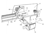
- FIG. 1 is a schematic perspective view of a medicine dispensing apparatus according to the present embodiment
- FIG. 2 is a view showing a state where an exterior panel 6 is removed.
- a medicine dispensing apparatus a plurality of cassettes 2 serving as storage containers are mounted in a lattice pattern without gaps on the apparatus main body 1, and a blister package 4 in which a plurality of medicines are packaged from each cassette 2 by a dispensing member 3 (FIG. 12). Reference) is paid out sequentially.
- the series of blister package 4 dispensing processes is executed by the control member 100 (see FIG. 15) based on prescription data input from a host computer (not shown) or the like. *
- the device main body 1 has a substantially rectangular parallelepiped shape by attaching an exterior panel 6 around the frame body 5.
- a transport device 7 for transporting a tray that is not to be transported is provided, and an upper region of the rear half is a cassette mounting portion 8.
- a roller conveyor is used as the conveying device 7, but various conveying means such as a belt conveyor and a pusher can be used.
- the cassette mounting portion 8 is provided with mounting members 8b on the opposing surface 8a of the support panel arranged at a predetermined interval in the left-right direction, and is configured so that the cassette 2 can be inserted into the mounting member 8b and mounted.
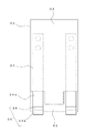
- the cassette 2 includes a substantially rectangular parallelepiped cassette body 9 having an open top surface and an opening / closing door 10 disposed on the front surface of the cassette body 9. Prepare. *
- a guide groove 11 is formed on the bottom surface of the cassette body 9.
- An extrusion member 12 is disposed in the cassette body 9 so as to be capable of reciprocating along the guide groove 11. Further, the pushing member 12 can urge the blister package 4 accommodated in the cassette body 9 with a constant load toward the door 10 regardless of the position of the pushing member 12 by a constant load spring (Conston) not shown. It has become. *
- an outlet 13 is formed at the front end of the bottom surface of the cassette body 9 so that the leading blister package 4 can be taken out.
- a part of the outlet 13 is closed by a closing piece (not shown) rotatably provided at the center of the front end of the bottom surface, and the leading blister package 4 is prevented from dropping.
- the closing piece is biased in the closing direction by a spring (not shown).
- the front plate 9 a of the cassette body 9 is formed with a recess 14 that extends vertically in the central portion on the inner surface side.
- the recess 14 is a relief for allowing the pressing portion 30 to move when the leading blister package 4 is taken out.
- the front plate 9a of the cassette body 9 faces the innermost side both sides (both sides of the recess 14 shown in FIG. It is preferable to form a concave curved surface 9b.
- the contact position with the front plate 9a can be set to the front side by the curved surface 9b. That is, even if the blister package 4 is curved, the position of the upper edge can be corrected so as not to be far from the front plate 9a. Therefore, even the blister package 4 that is curved can be smoothly pushed down by the pressing portion 30 of the payout member 3 described later.
- the guide plate 48 includes a first curved surface 49a that gradually protrudes upward toward the front plate 9a. Further, a second curved surface 49b (guide surface) formed in a convex shape is provided at the tip portion from the first curved portion 49a. The second curved surface 49b guides the blister package 4 slidably contacting the outlet to the outlet 13, and applies a force in a direction that is straight if the blister package 4 is curved in the short direction. .
- the position of the guide plate 48 can be adjusted in the width direction (the direction perpendicular to the paper surface in FIG. 12A).
- the guide plate 48 can be positioned between the plurality of pocket portions for storing the medicines of the blister package 4.
- the guide plate 48 is attached to the front plate 9a with a slight gap through which only one sheet portion of the blister package 4 (a flat portion to which a cover film is attached as described later) can pass. It has been. Thereby, the lower edge part of the blister package 4 located in the vicinity of the outlet 13 can be reliably supported, and it is prevented that the blister package 4 overlaps and is discharged or clogged. Further, the closing piece or the like can be eliminated.
- both side surfaces of the cassette body 9 have guide surface portions 9 c that protrude further forward from the front surface.
- Each guide surface portion 9c is formed with a locking hole 9d at an opposing position, and a locking projection (not shown) attached to the recess 10a of the open / close door 10 can be engaged and disengaged.
- a locking projection (not shown) is locked in the locking hole 9d, and the opening / closing door 10 can be positioned in the closed position.
- a guide hole 9e is formed in one guide surface portion 9c, and a guide pin 46 of a drive mechanism 37 described later can be engaged and disengaged.
- a plurality of blister packs 4 (PTP (Press Through Package) sheets) are stacked and accommodated horizontally in the cassette body 9.
- the blister pack 4 has a plurality of pockets for storing the medicine, and a cover film is attached so as to close the pockets.
- the stacking direction of the blister package 4 is set so that the cover film side faces the front side of the cassette body 9.
- the open / close door 10 is attached to the lower front end of the cassette body 9 so as to be rotatable about a support shaft 10 a.
- the open / close door 10 includes a bearing portion 15 that is rotatably attached to the support shaft 10 a, a front surface portion 16 that extends from the bearing portion 15, and a guide receiving portion 17 that is bent from the front end edge of the front surface portion 16 into a substantially U-shaped cross section. It consists of. *
- the bearing portion 15 is integrated with an end surface 15b formed with an operation hole 15a in which a rotation pin 43 of the payout member 3 described later is engaged and disengaged on one end side thereof.
- the front surface portion 16 has a flat plate shape, and a notch portion 18 is formed in the central portion of one side edge thereof. Using this notch 18, it is possible to grip the fraction of the blister package 4 by a grip member 24 described later.
- the guide receiving portion 17 has a reference surface 17a on which the side edge portion (lower edge portion) of the fraction (residue) of the blister package 4 is abutted and positioned.
- the leading edge of the guide receiving portion 17 bent into a U shape is formed in a circular cross section, and recessed portions 10a are formed at both ends thereof, respectively, and when the open / close door 10 is positioned at the closed position, A locking projection (not shown) that is locked to the locking hole 9b of the guide surface 9a is provided.
- the open / close door 10 is rotated 180 degrees from the normal payout position (FIG. 3) in which the rotation pin 43 of the payout member 3 is engaged with the operation hole 15a and turned to the front end side of the cassette body 9, and the closed position. Positioning is possible at the fraction payout position (FIG. 4).
- the blister package 4 is positioned with respect to the reference surface 17a by bringing the lower edge of the blister package 4 into contact with the reference surface 17a.
- a holding piece 19 is rotatably attached to the support shaft 10a.
- the holding piece 19 is urged toward the front face 16 side (shown in the direction of arrow a in FIG. 6) by a coil spring (not shown) attached to the support shaft 10a.
- the holding piece 19 is integrated with a sucked portion 20 made of a magnetic material at a lower end portion on one end side.
- the attracted portion 20 is attracted by a magnet 52 (see FIG. 7), which will be described later, the holding piece 19 rotates in the direction of the arrow b in FIG.
- the holding state of the blister package 4 is released.
- the blister package 4 is positioned in the vertical direction by bringing its lower edge portion into contact with the reference surface 17a.
- a magnetic part and a light emitting part are provided on the front surface of the cassette.
- This magnetic part is attracted to an electromagnet part (not shown) provided on the support plate 21 side described later when the cassette 2 is pulled out from the cassette mounting part 8.
- the light emitting unit is irradiated with light from an LED (not shown) provided on the apparatus main body 1 side.
- the light emitting unit is irradiated with the LED when, for example, a chemical shortage or abnormality is notified. According to this, it is possible to eliminate the need for electrical components and wiring on the cassette 2 side, and it is possible to simplify the configuration and manufacture at a low cost.
- the dispensing member 3 includes a support plate 21, a first dispensing member 22, a second dispensing member 23, a gripping member 24, a cutting member 25, and A recovery member 26 is provided.
- the support plate 21 is provided so as to be able to reciprocate on a horizontal rail 28 that can be raised and lowered with respect to a vertical rail 27 arranged on the front left and right of the apparatus main body 1.
- the first payout member 22 meshes with the rack 29 through a gear 22 b provided on the rotation shaft of the motor 22 a and drives the motor 39 to rotate forward and reverse, thereby causing the rack 29 to be interposed via the arm portion 31.
- the integrated pressing unit 30 is moved up and down. *
- the pressing portion 30 extends downward with its upper end screwed to the tip of an arm portion 31 extending in the horizontal direction from the rack 29. As shown in FIGS. 11 and 12, the pressing portion 30 has a back surface portion 33 integrated with the back surface of the front plate 32. A gap is formed between the front plate 32 and the back surface portion 33, and elastic pieces 34 are fixed to the upper portions on both sides. In the back surface portion 33, the lower end positions of both side portions are positioned higher than the lower end position of the front plate 32, and the lower end portion of the elastic piece 34 is exposed there.
- the elastic piece 34 includes a linear portion 34a that gradually inclines toward the back surface 33 as it goes downward from the fixed position, and a curved portion 34b that curves toward the front plate 32 at a portion exposed downward from the back surface 33. It consists of A locking piece 35 protrudes from the curved portion 34b.
- the locking piece 35 may be formed by cutting and raising a part of the elastic piece 34, or may be formed by separately integrating small pieces by adhesion or the like.
- the curved portion 34 b and the locking piece 35 constitute a guide portion 36. As will be described later, the guide portion 36 is for reliably guiding and pushing down the upper edge of the blister package 4 regardless of the curved state of the blister package 4.
- the blister package 4 when the blister package 4 is deformed so that the side edge of the blister package 4 is curved toward the elastic piece 34, the blister package 4 is pressed by the elastic piece 34 so as to suppress deformation. be able to.
- the protruding dimension of the locking piece 35 from the curved portion 34 b is substantially the same as the thickness of the sheet portion of the blister package 4. Accordingly, even if the blister package 4 to be pushed down is curved as described above and approaches the next adjacent blister package 4, the locking piece 35 interferes with the blister package 4. There is nothing.
- the said elastic piece 34 was provided two, it is also possible to comprise by one. *
- the second payout member 23 includes an electromagnet part (not shown) and a drive mechanism 37. *
- the electromagnet portion is excited by energization, attracts the magnetic portion of the cassette 2 at the forward position, and retracts the cassette 2 from the cassette mounting portion 8 to the medicine extraction position by moving backward.
- the drive mechanism 37 is configured to transmit the driving force of the motor 39 provided on the mounting plate 38 having a substantially L-shaped cross section to the rotation pin 43 through a gear, and slides in the width direction according to the size of the cassette 2. It is possible. Here, three guide positions corresponding to three types of cassettes 2 of different sizes can be positioned at one guide position and one retracted position. *
- the details of the drive mechanism 37 are as follows. That is, a drive gear 40 is provided on the rotating shaft of the motor 39, an intermediate gear 41 is engaged with the drive gear 40, and a driven gear 42 is engaged with the intermediate gear 41.
- a driven plate 44 having a rotation pin 43 is integrated with the end face of the driven gear 42.
- the pivot pin 43 can be engaged and disengaged with an operation hole 15 a formed in the bearing portion 15 of the opening / closing door 10 at the tip end portion.
- the mounting plate 38 is integrated with a guide pin 46 that is positioned in the guide hole 9 e of the cassette body 9. The distal end of the guide pin 46 is formed in a conical shape, so that it can easily enter the guide hole 9e.
- the driven plate 44 that is, the rotation pin 43 rotates via the gear. Move. Thereby, the open / close door 10 is rotated to the normal payout position and the fraction payout position around the support shaft 10a while being positioned by the guide pin 46. It is preferable to provide a torque limiter or the like in any of the power transmission paths from the motor 39 to the driven plate 44 (for example, on the rotating shaft of the driven gear 42). As a result, when the door 10 is rotated to the closed position by the drive mechanism 37, a load more than necessary does not act on the cassette body 9 side, and damage can be prevented. *
- the grip member 24 includes a pair of grip pieces 47.
- the grip piece 47 is provided in the front portion of the support plate 21 so as to be reciprocally movable in the horizontal direction.
- a rack (not shown) formed on the opposing surface of an arm 47a (one not shown) extending from each gripping piece 47 via a pinion (not shown) provided on the rotation shaft of the motor 24a. It is opened and closed by being transmitted to (not shown). Further, one end portion (free end portion) of each gripping piece 47 is bent in a crank shape to constitute a gripping portion 50 facing each other.
- Through-holes are respectively formed in the gripping portions 50, and it is possible to detect whether or not the blister package 4 is sandwiched through the through-holes by an optical sensor 51 provided on one gripping piece 47.
- One grip piece 47 is provided with a magnet 52 (here, a neodymium magnet is used). The magnet 52 is for attracting the attracted portion 20 provided on the holding piece 19 of the opening / closing door 10 and rotating the holding piece 19 to separate it from the front face portion 16.
- the cutting member 25 is obtained by attaching a pair of cutting blades 55 (see FIG. 14) that can be brought into and out of contact with a support base 53 with a gap 54 interposed therebetween.
- One end surface of the support base 53 is fixed to a fan-shaped rotation plate 56 that is a position adjusting member.
- the rotation plate 56 has a gear formed on the outer peripheral edge. The gear meshes with a gear provided on the rotating shaft of the motor 56a. Then, by driving the motor 56a, the rotating plate 56 rotates forward and backward via the gear. Thereby, the cutting blade 55 rotates with the rotation plate 56, and the cutting position with respect to the blister package 4 grasped by the grasping member 24 is changed.
- the cutting member 25 is positioned and used at two positions, a horizontal position (FIG. 9) and a vertical position. Moreover, the cutting member 25 is provided with an elevating mechanism (not shown) so that the cutting position by the cutting blade 55 can be adjusted. Thereby, it is possible to cut
- a holding member (not shown) for preventing the positional shift of the blister package 4 inserted in the gap of the support base 53 is provided, and the positional shift (jumping etc.) of the blister package 4 due to the impact at the time of cutting is provided. It is preferable to prevent. *
- the collection member 26 includes a guide passage 57 and a collection container 58.
- the guide passage 57 includes a straight portion 57a and an inclined portion 57b.
- the blister package 4 that falls from the outlet 13 of the cassette 2 passes through the straight portion 52a, and the inclined portion 52b is cut by the cutting member 25.
- the blister package 4 of the other fraction passes and joins the straight part 52a.
- the collection container 58 has three storage parts (not shown), and the blister package 4 supplied through the guide passage 57 is divided into compartments in a tray (not shown) that is conveyed by the conveying device 7. Transport to. *
- step S1 If prescription data is input from a host computer (not shown) or the like (step S1), the dispensing member 3 is moved to the cassette 2 in which the blister pack 4 of the corresponding medicine is stored based on the input prescription data (step S1). Step S2). Then, it is determined whether or not the blister package 4 is to be paid out as a whole sheet (step S3). This determination may be made based on whether or not the number of drugs included in the prescription data is larger than the number of drugs per sheet of the blister package 4. At this time, the number of blister packs 4 to be paid out is calculated. This operation may be determined by how many times the former quantity is greater than the latter quantity. When a plurality of blister packs 4 are paid out, the surplus number is paid out in the processing after step S10 described later.
- step S3 When paying out the blister package 4 as a whole (step S3: YES), the support plate 21 is moved to excite the electromagnet portion. Thereby, since the magnetic part of the cassette 2 is attracted
- the blister package 4 is often delivered in a state where a plurality of blister packs 4 are bundled with rubber bands or the like. For this reason, the blister package 4 may be bent in the short direction with respect to the vertical plane in a state where it is set in the cassette body 9.
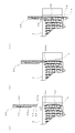
- the pressing portion 30 has the guide portion 36 formed at the lower end portion of the elastic piece 34. Therefore, even if the blister package 4 to be pushed down is curved as shown in FIG. 13A, when the pressing portion 30 is moved downward, the blister package 4 is changed from FIG. 13B to FIG. 13C. As shown in FIG. 4, the upper edge portion of the leading blister package 4 can always be guided by the guide portion 36.
- the blister package 4 is urged in the direction in which the curved shape is corrected by the elastic force of the elastic piece 34. Therefore, even the blister package 4 that is curved can be smoothly discharged from the cassette 2 through the outlet 13.
- the discharged blister package 4 is collected into the collection container 58 through the guide passage 57.
- the pressing unit 30 raises the next blister package 4 in order to push it down (step S6).
- step S7 it is determined whether or not the number of blister packs 4 to be paid out as a whole sheet has reached a predetermined number calculated based on the prescription data (step S7). If the predetermined number has not been reached, the process returns to step S5 to repeat the pressing operation for lowering the pressing unit 30 (step S5) and the returning operation for increasing (step S6). If the predetermined number has been reached, it is determined that the delivery of the blister package 4 has been completed, and the electromagnet part is advanced to accommodate the cassette 2 in the cassette mounting part 8 (step S8). Then, the collection container 58 (dispensing member 3) is moved to a tray (not shown) (step S9). *
- step S3 NO
- the opening / closing door 10 is rotated 180 degrees by the rotation pin 43 and positioned at the fraction discharge position (step S10). Then, it is determined whether or not the fractional blister package 4 is held by the open / close door 10 (fractional holding?) (Step S11). *
- step S11 If the blister package 4 of the fraction is not held on the opening / closing door 10 (step S11: YES), the blister package 4 positioned at the head is pushed down by the pressing unit 30 in the same manner as described above and discharged through the outlet 13. (Step S12). The discharged blister package 4 is sandwiched between the front plate 32 and the holding piece 19 by the holding piece 19 biased toward the front plate 32 by the coil spring.
- step S13 If the fractional blister package 4 is held in the open / close door 10, it is determined whether or not the quantity N1 of the medicine is equal to or greater than the quantity N2 desired to be dispensed in the prescription data (step S13). If N1 ⁇ N2, steps S16 to S30 described later are executed. If N1 ⁇ N2, the fractional blister package 4 is gripped by the gripping member 24 and dispensed to the collection container 58 (step S14), and the remaining fraction is calculated (step S15). Steps S16 to S30 described later are executed for the minute. *
- the holding member 24 is brought close to the open / close door 10 (step S16). Then, when the grip piece 47 is separated and the blister package 4 is moved to a position where it can be gripped, the magnet 52 provided in the vicinity of the grip member 24 sucks the sucked portion 20 provided on the holding piece 19, and FIG. As shown, the holding piece 19 rotates in a direction away from the front surface portion 16. The blister package 4 loses its holding by the holding piece 19 and falls until its lower edge is brought into contact with the guide receiving portion 17. Thereby, the blister package 4 can be always positioned at the same position in the vertical direction with respect to the reference surface 17a of the guide receiving portion 17 of the door 10.
- the blister package 4 can always be positioned immediately before the blister package 4 is gripped by the gripping member 24.
- the timing of the rotation of the holding piece 19 by the magnet 52 is not particularly limited, for example, after the cutting by the cutting member 25.
- the blister package 4 is discharged vertically downward through the outlet 13 of the cassette 2 by the pressing portion 30, the blister package 4 is hardly displaced in the horizontal direction.
- the gripping member 24 is driven, and the ear portion of the blister package 4 is gripped by the gripping piece 47 through the notch 18 formed in the guide receiving portion 17 (step S17). At this time, the ear portion of the blister package 4 is detected based on the detection signal from the optical sensor 51, and it is confirmed that the blister package 4 is securely held by the holding piece 47. Then, the gripping member 24 is moved horizontally to the cutting position of the cutting member 25 (step S18). In the cutting member 25, a rotation position is changed according to the fraction of the blister package 4. *
- step S19 When the pocket part of the blister package 4 is an even number row (2 rows or 4 rows), it is determined whether or not the fraction is an even number (step S19). If the fraction is an even number (step S19: YES), the cutting member 25 is set to a vertical position rotated 90 degrees (step S20), and the portion to be cut off by adjusting the position of the gripping member 24 is a desired quantity. Positioning is performed (step S21). Thus, when the blister package 4 is cut in the lateral direction by the cutting member 25 (step S22), the desired fraction is collected into the collection container 58 through the guide passage 57. *
- step S15 If the fraction is an odd number (step S15: NO), the blister package 4 is cut in the horizontal direction as described above (steps S23 to S25), and then the remaining one from the remaining blister package 4 is cut. .
- the rotating plate 56 is rotated 90 degrees to the horizontal position (step S27), and only half is further cut. What is necessary is just to cut
- the cutting blade 55 is once opened by a predetermined dimension as shown in FIG. 14B (step S29).
- the open dimension at this time is such that the interval between the cutting blades 55 is wider than the thickness of the sheet portion of the blister package 4 and does not exceed the entire thickness including the pocket portion.
- FIGS. 14C to 14D when the gripping member 24 is moved in the horizontal direction (step S30), it is forcibly even if it is not successfully separated at the boundary portion of the cut portion. It becomes possible to separate.
- FIG. 14 although it is explanatory drawing in the case of cut
- the remaining blister package 4 with the fractions cut in this way is moved to the guide receiving portion 17 of the door 10 by moving the gripping member 24 (step S31). And the remaining blister package 4 is clamped with the holding piece 19 provided in the guide receiving part 17 by canceling
- the holding piece 19 of the door 10 is separated from the front surface portion 16 by the action of the magnet 52, and a gap is formed. Therefore, the blister package 4 can be smoothly positioned between the front surface portion 16 and the holding piece 19 simply by moving the gripping member 24.
- the holding piece 19 is rotated by the biasing force of the coil spring, and the blister package 4 is sandwiched between the front surface portion 16. can do. Further, if the blister package 4 is sandwiched, the support position by the holding piece 19 is stored as coordinate data together with the remaining quantity (number of pockets), and the gripping member is based on this data at the next dispensing. What is necessary is just to move 24 and pay out the remaining blister package 4. Then, if there is no remaining blister package 4 held in the guide receiver 17, the new blister package 4 is discharged from the cassette 2 to the guide receiver 17 and cut in the same manner as described above. That's fine.
- the pushing direction by the pressing unit 30 is not limited to the vertically downward direction, and may be a horizontal direction.
- the extrusion direction of the blister package 4 is not limited to the short direction, and may be the longitudinal direction.
- the ear portion of the blister package 4 (a flat plate portion separable from the pocket portion side) may be positioned on the lower side.
- the accommodating direction of the blister package 4 is rotated by 90 degrees, and the longitudinal direction thereof is directed in the vertical direction. What is necessary is just to push down, and the press part 30 may be rotated 90 degree
- the cutting method is not limited to this.
- two medicines are cut from two rows of blister packs 4, it is possible to cut two medicines from one row as shown in FIG. *
- FIG. 18 it is good also as a structure which can pay out two blister package bodies 4 simultaneously.
- the protruding sides of the tablet accommodating portion of the blister package 4 are brought into contact with each other.
- the two blister packs 4 can be easily transferred together.
- the blister package 4 is contained in a box in such a state that the two blisters are joined together. For this reason, it is possible to take out the blister package 4 from the delivered box and set it as it is.
- the push-down unit 30 only needs to be configured to be able to push down the two blister packages 4 by the bottom surface.
- the push-down portion 30 is formed in a flat plate shape so that the overlapped pocket portion is pushed down on the bottom surface thereof.
- interval of the taking-out port 13 of the cassette 2 be a value which the two blister package bodies 4 can pass. Accordingly, when the pressing portion 30 is moved downward from the state shown in FIG. 18A, the two blister packs 4 are pushed down on the bottom surface, and are discharged from the outlet 13 as shown in FIG. 18B. Is done. Then, as shown in FIG.
- the holding piece 19 is rotated in a non-contact manner by the attractive force of the magnet 52 provided on the gripping member 24 as the operating portion. It is also possible to have a configuration in which the lens is directly abutted on and rotated. Moreover, although the plate-shaped holding piece 19 was used as a holding
- the position of the cutting member 25 relative to the blister package 4 gripped by the gripping member 24 is changed by rotating the rotating plate 56.
- the position of the blister package 4 gripped by the gripping member 24 relative to the cutting member 25 may be changed by rotating the gripping member 24 or by rotating both the cutting member 25 and the gripping member 24.
- the pressing unit 30 can be configured as follows. *
- a plate member and an urging member for urging the plate member may be provided instead of the elastic piece 34.
- the plate material is preferably made of resin, but may be made of metal or the like.
- various things, such as urethane rubber and a coil spring, can be used for a biasing member. By comprising the plate material and the urging member, the durability can be improved as compared with the case of using a leaf spring.
- the payout member 3 may be configured by a roller member instead of the holding piece 19 formed by a leaf spring.
- a roller member 60 in which a rubber roller is integrated around a rotation shaft and can be driven to rotate can be used.
- a notch 61 (or an opening) is formed in the front plate 9 a of the cassette body 9 in the vertical direction, and the roller member 60 is pressed against the blister package 4 positioned at the head via the notch 61. Then, by rotating the roller member 60, the blister package 4 is discharged downward through the outlet 13.
- the blister package 4 of the fraction is held by the guide receiving portion 17 with the door 10 being rotated 180 degrees. It is good also as just forming the accommodating part which can accommodate the blister package 4 of a fraction, without making it move.
- the blister package 4 may be transferred to the housing portion by the gripping member 24.
- Second payout member 24 ... Grip member 25 ... Cutting member 26 ... Collection member 27 ... Vertical rail 28 ... Horizontal rail 29 ... Rack 30 ... Push-down part 31 ... Arm part 32 ... Front plate 33 ... Back part 34 ... Elastic piece 35 ... Locking piece 36 ... Guide part 37 ... Drive mechanism 38 ... Mounting plate 39 ... Motor 40 ... Drive gear 41 ... Intermediate gear 42 ... Driven gear 43 ... Rotating pin 44 ... Driven Plate 45 ... Operating hole 46 ... Guide pin 47 ... Grip piece 48 ... Guide plate 49a ... First curved surface 49b ... Second curved surface 50 ... Grip portion 51 ... Photo sensor 52 ... Magnet 53 ... Support base 54 ... Fixed blade 55 ... Movable blade 56 ... Rotating plate 57 ... Guide passage 58 ... Collection container
Abstract
Description
に、先頭のブリスター包装体4を取出可能とする取出口13が形成されている。取出口13は、底面前端部の中央に回動可能に設けた閉鎖片(図示せず)によってその一部が閉鎖され、先頭のブリスター包装体4の落下が防止されている。閉鎖片はスプリング(図示せず)によって閉鎖方向に付勢されている。 Further, as shown in FIG. 5, an
され、一方の把持片47に設けた光センサ51により前記貫通孔を介してブリスター包装体4が挟持されているか否かを検出できるようになっている。また、一方の把持片47には磁石52(ここでは、ネオジウム磁石を使用)が設けられている。この磁石52は、開閉扉10の保持片19に設けた被吸引部20を吸引し、この保持片19を回動させて前面部16から離間させるためのものである。 As shown in FIGS. 7 and 10, the
保持片19の間に位置させることができる。このため、把持部材24による把持状態を解除し、この把持部材24を移動させれば、保持片19がコイルスプリングの付勢力によって回動し、前面部16との間にブリスター包装体4を挟持することができる。また、ブリスター包装体4が挟持されれば、保持片19による支持位置を座標データとして残余の数量(ポケット部の数)と共に記憶しておき、次回の払出の際、このデータに基づいて把持部材24を移動させ、残余のブリスター包装体4を払い出すようにすればよい。そして、ガイド受部17に保持している残余のブリスター包装体4がなくなれば、前記同様にして、新たなブリスター包装体4をカセット2からガイド受部17へと排出し、切断するようにすればよい。 The remaining
2…カセット(収容容器)
3…払出部材
4…ブリスター包装体
5…枠体
6…外装パネル
7…搬送装置
8…カセット装着部
9…カセット本体
9a…ガイド面
9b…湾曲面
9c…ガイド面部
9d…係止孔
9e…ガイド孔
10…開閉扉
11…ガイド溝
12…押出部材
13…取出口
14…凹所
15…軸受部
16…前面部
17…ガイド受部
18…切欠部
19…保持片
20…被吸引部
21…支持板
22…第1払出部材
23…第2払出部材
24…把持部材
25…切断部材
26…回収部材
27…垂直レール
28…水平レール
29…ラック
30…押下部
31…腕部
32…前面板
33…背面部
34…弾性片
35…係止片
36…ガイド部
37…駆動機構
38…取付プレート
39…モータ
40…駆動ギア
41…中間ギア
42…従動ギア
43…回動ピン
44…従動プレート
45…操作孔
46…ガイドピン
47…把持片
48…ガイドプレート
49a…第1湾曲面
49b…第2湾曲面
50…把持部
51…光センサ
52…磁石
53…支持台
54…固定刃
55…可動刃
56…回動プレート
57…案内通路
58…回収容器 1 ...
DESCRIPTION OF
Claims (7)
- 装置本体と、
薬剤が個別に包装される複数のブリスター包装体を重ねた状態で収容し、前記ブリスター包装体の重なり方向が水平又は略水平方向となるように、前記装置本体に取り付けられる収容容器と、
前記装置本体に移動可能に設けられ、前記収容容器まで移動して、収容したブリスター包装体を払い出させる払出部材と、
前記払出部材によって払い出されたブリスター包装体を把持して搬送する把持部材と、
前記把持部材に把持されて搬送されてきたブリスター包装体から端数分を切断する切断部材と、を備え、
前記収容容器は、一端側底面に形成される、ブリスター包装体を取り出すための取出口と、収容したブリスター包装体を前記取出口側に向かって付勢する付勢部材と、前記取出口側の外端面に配置される開閉扉と、を備え、
前記開閉扉は、収容容器の取出口から排出されたブリスター包装体をガイドするガイド受部と、前記ブリスター包装体をガイド受部との間に保持する保持位置と解放する解放位置とに移動可能な保持部と、前記保持部を保持位置に付勢する付勢部とを有し、前記ガイド受部は、前記保持部を解放位置に移動させた際、ブリスター包装体の下縁部が当接して位置決め可能な基準面を有し、
前記把持部材は、前記付勢部の付勢力に抗して保持部を保持位置から解放位置に移動させる作動部を備えたことを特徴とする薬剤払出装置。 The device body;
Containing a plurality of blister packs in which medicines are individually wrapped in a stacked state, and a storage container attached to the apparatus main body so that the overlapping direction of the blister packs is horizontal or substantially horizontal;
A payout member that is movably provided in the apparatus main body, moves to the storage container, and discharges the stored blister package;
A gripping member for gripping and transporting the blister package paid out by the payout member;
A cutting member for cutting a fraction from the blister package that has been gripped and conveyed by the gripping member,
The storage container has an outlet for taking out the blister package, a biasing member for biasing the stored blister package toward the outlet, and formed on a bottom surface on one end side. An open / close door disposed on the outer end surface,
The open / close door is movable between a guide receiving portion for guiding the blister package discharged from the container outlet, a holding position for holding the blister package between the guide receiving portion and a release position for releasing the blister package. A holding portion and an urging portion for urging the holding portion to the holding position, and when the holding portion is moved to the release position, the lower edge portion of the blister package is applied to the guide receiving portion. It has a reference surface that can be positioned in contact with it,
The medicine dispensing device, wherein the gripping member includes an operation unit that moves the holding unit from the holding position to the release position against the urging force of the urging unit. - 前記把持部材は、開閉可能な一対の保持片と、前記ブリスター包装体を検出可能なセンサとを有することを特徴とする請求項1に記載の薬剤払出装置。 2. The medicine dispensing apparatus according to claim 1, wherein the gripping member has a pair of holding pieces that can be opened and closed, and a sensor that can detect the blister package.
- 前記開閉扉は、払出部材によるブリスター包装体の払出動作を許容する通常払出位置と、払出部材によるブリスター包装体の払出動作を許容して、払い出したブリスター包装体を保持部に保持可能とする端数払出位置とに位置決め可能であり、
前記把持部材は、前記端数払出位置で、開閉扉の保持部に保持されたブリスター包装体を把持して切断部材へと搬送可能であり、切断部材で端数分を切断された後のブリスター包装体の残余を搬送して開閉扉の保持部に保持させることを特徴とする請求項1又は2に記載の薬剤払出装置。 The opening / closing door is a normal dispensing position that allows the blister package to be dispensed by the dispensing member, and a fraction that allows the blister package to be dispensed by the dispensing member and holds the dispensed blister package in the holding portion. It can be positioned at the payout position,
The gripping member is capable of gripping the blister packaging body held by the holding portion of the open / close door at the fraction dispensing position and transporting it to the cutting member, and the blister packaging body after the fractional portion has been cut by the cutting member The medicine dispensing apparatus according to claim 1, wherein the remainder is conveyed and held by a holding portion of the door. - 前記開閉扉にブリスター包装体を保持する際、前記把持部材を駆動制御して、一旦、作動部で保持部を解放位置に回動させることにより、基準面に対してブリスター包装体の下縁部を自重により位置決めさせる制御部材を備えたことを特徴とする請求項1から3のいずれか1項に記載の薬剤払出装置。 When holding the blister package on the door, the lower edge of the blister package with respect to the reference surface is controlled by driving the gripping member and rotating the holding unit to the release position once by the operating unit. The medicine dispensing device according to any one of claims 1 to 3, further comprising a control member that positions the body by its own weight.
- 前記開閉扉の保持部は磁性材料からなり、
前記把持部材の作動部は、前記保持部を吸引可能な磁石からなることを特徴とする請求項1から4のいずれか1項に記載の薬剤払出装置。 The holding part of the door is made of a magnetic material,
The medicine dispensing device according to any one of claims 1 to 4, wherein the operating part of the gripping member is made of a magnet capable of attracting the holding part. - 前記把持部材は、一方の保持片に磁石を備え、保持片が開放位置に位置するとき、前記開閉扉の保持部を吸引してブリスター包装体の保持状態を解除することを特徴とする請求項5に記載の薬剤払出装置。 The holding member includes a magnet in one holding piece, and when the holding piece is located in an open position, the holding member of the opening / closing door is sucked to release the holding state of the blister package. 5. The medicine dispensing device according to 5.
- 装置本体と、
薬剤が個別に包装される複数のブリスター包装体を重ねた状態で収容し、前記ブリスター包装体の重なり方向が水平又は略水平方向となるように、前記装置本体に取り付けられる収容容器と、
前記装置本体に移動可能に設けられ、前記収容容器まで移動して、収容したブリスター包装体を払い出させる払出部材と、
前記払出部材によって払い出されたブリスター包装体を把持して搬送する把持部材と、
前記把持部材に把持されて搬送されてきたブリスター包装体から端数分を切断する切断部材と、を備えた薬剤払出装置で行う薬剤払出方法であって、
前記開閉扉にブリスター包装体を保持する際、前記把持部材を駆動制御して、一旦、作動部で保持部を解放位置に回動させることにより、基準面に対してブリスター包装体の下縁部を自重により位置決めすることを特徴とする薬剤払出方法。 The device body;
Containing a plurality of blister packs in which medicines are individually wrapped in a stacked state, and a storage container attached to the apparatus main body so that the overlapping direction of the blister packs is horizontal or substantially horizontal;
A payout member that is movably provided in the apparatus main body, moves to the storage container, and discharges the stored blister package;
A gripping member for gripping and transporting the blister package paid out by the payout member;
A medicine dispensing method comprising: a medicine dispensing device provided with a cutting member that cuts a fraction from a blister package that has been grasped and conveyed by the grasping member,
When holding the blister package on the opening / closing door, the lower edge portion of the blister package with respect to the reference surface is controlled by driving the gripping member and rotating the holding unit to the release position once by the operating unit. A medicine dispensing method characterized by positioning by weight.
Priority Applications (5)
| Application Number | Priority Date | Filing Date | Title |
|---|---|---|---|
| CN201180031845.1A CN102958492B (en) | 2010-06-30 | 2011-06-28 | Drug dispensing device and drug dispensing method |
| KR1020127033677A KR20130105793A (en) | 2010-06-30 | 2011-06-28 | Drug dispensing device and drug dispensing method |
| EP11800806.9A EP2589369A4 (en) | 2010-06-30 | 2011-06-28 | Drug dispensing device and drug dispensing method |
| US13/806,137 US9056705B2 (en) | 2010-06-30 | 2011-06-28 | Medicament dispensing machine and medicament dispensing method |
| JP2012507494A JP4985897B2 (en) | 2010-06-30 | 2011-06-28 | Drug dispensing device |
Applications Claiming Priority (2)
| Application Number | Priority Date | Filing Date | Title |
|---|---|---|---|
| JP2010-149071 | 2010-06-30 | ||
| JP2010149071 | 2010-06-30 |
Publications (1)
| Publication Number | Publication Date |
|---|---|
| WO2012002342A1 true WO2012002342A1 (en) | 2012-01-05 |
Family
ID=45402050
Family Applications (1)
| Application Number | Title | Priority Date | Filing Date |
|---|---|---|---|
| PCT/JP2011/064721 WO2012002342A1 (en) | 2010-06-30 | 2011-06-28 | Drug dispensing device and drug dispensing method |
Country Status (7)
| Country | Link |
|---|---|
| US (1) | US9056705B2 (en) |
| EP (1) | EP2589369A4 (en) |
| JP (2) | JP4985897B2 (en) |
| KR (1) | KR20130105793A (en) |
| CN (1) | CN102958492B (en) |
| TW (1) | TW201206417A (en) |
| WO (1) | WO2012002342A1 (en) |
Cited By (3)
| Publication number | Priority date | Publication date | Assignee | Title |
|---|---|---|---|---|
| JP2014213150A (en) * | 2013-04-30 | 2014-11-17 | キヤノンマーケティングジャパン株式会社 | Tablet stripping device, tablet stripping system, control method and program |
| US9150119B2 (en) | 2013-03-15 | 2015-10-06 | Aesynt Incorporated | Apparatuses, systems, and methods for anticipating and delivering medications from a central pharmacy to a patient using a track based transport system |
| US9511945B2 (en) | 2012-10-12 | 2016-12-06 | Aesynt Incorporated | Apparatuses, systems, and methods for transporting medications from a central pharmacy to a patient in a healthcare facility |
Families Citing this family (8)
| Publication number | Priority date | Publication date | Assignee | Title |
|---|---|---|---|---|
| SG11201507870UA (en) * | 2013-04-23 | 2015-11-27 | Yuyama Mfg Co Ltd | Medicine dispensing device, medicine dispensing method, and medicine storage cassette |
| JP5950883B2 (en) * | 2013-10-18 | 2016-07-13 | 株式会社トーショー | Tablet cutting blade replacement jig |
| CA2982433C (en) * | 2015-04-11 | 2023-06-20 | Yuyama Mfg. Co., Ltd. | Medicine dispensing cassette |
| US10751257B2 (en) * | 2015-05-06 | 2020-08-25 | Aceage Inc. | Medication delivery apparatus |
| NL2019530B1 (en) * | 2017-09-12 | 2019-03-27 | Canister Dev B V | Device for packaging dosed quantities of solid medicines |
| US10741275B2 (en) * | 2017-09-14 | 2020-08-11 | Dosepack Corporation | Medicine dispensing system with feedback pre-fill apparatus |
| WO2021081632A1 (en) * | 2019-11-01 | 2021-05-06 | Aceage Inc. | Medication delivery apparatus |
| US11935352B2 (en) * | 2022-08-15 | 2024-03-19 | Bryan Hakim | Touchless food dispenser |
Citations (3)
| Publication number | Priority date | Publication date | Assignee | Title |
|---|---|---|---|---|
| JP2818759B2 (en) | 1989-03-29 | 1998-10-30 | 高園産業株式会社 | Blister package removal device |
| JP2006109859A (en) | 2004-10-12 | 2006-04-27 | Tosho Inc | Dispensing medicament put-out device |
| WO2010032479A1 (en) * | 2008-09-19 | 2010-03-25 | 株式会社湯山製作所 | Medication dispensing device and medication dispensing method |
Family Cites Families (10)
| Publication number | Priority date | Publication date | Assignee | Title |
|---|---|---|---|---|
| US4546901A (en) * | 1984-02-02 | 1985-10-15 | Buttarazzi Patrick J | Apparatus for dispensing medication |
| JPH04272758A (en) | 1991-02-27 | 1992-09-29 | Copal Co Ltd | Prescription device |
| JP4121190B2 (en) * | 1998-07-15 | 2008-07-23 | 株式会社トーショー | Dispensing system |
| UA73759C2 (en) * | 1999-12-29 | 2005-09-15 | Kba Giori Sa | Method and machine for cutting of bond paper strips |
| US7100792B2 (en) * | 2002-08-30 | 2006-09-05 | Omnicell, Inc. | Automatic apparatus for storing and dispensing packaged medication and other small elements |
| US7686184B2 (en) * | 2004-05-19 | 2010-03-30 | Yuyama Mfg. Co., Ltd. | Medicine dispensing device |
| JP4347183B2 (en) * | 2004-10-12 | 2009-10-21 | 株式会社トーショー | Vibration discharge cassette |
| CN102173332B (en) | 2004-10-12 | 2012-11-07 | 株式会社东商 | Vibration-based ejection cassette, drug dispensing apparatus, ptp dispensing apparatus, pharmaceutical product storage apparatus and ptp dispensing system |
| JP4520814B2 (en) * | 2004-10-15 | 2010-08-11 | 株式会社湯山製作所 | Chemical dispensing device |
| US20060266188A1 (en) * | 2005-05-25 | 2006-11-30 | Jvm Co., Ltd. | Apparatus for cutting series of medicine packets |
-
2011
- 2011-06-28 CN CN201180031845.1A patent/CN102958492B/en not_active Expired - Fee Related
- 2011-06-28 KR KR1020127033677A patent/KR20130105793A/en not_active Application Discontinuation
- 2011-06-28 JP JP2012507494A patent/JP4985897B2/en not_active Expired - Fee Related
- 2011-06-28 WO PCT/JP2011/064721 patent/WO2012002342A1/en active Application Filing
- 2011-06-28 EP EP11800806.9A patent/EP2589369A4/en not_active Withdrawn
- 2011-06-28 US US13/806,137 patent/US9056705B2/en not_active Expired - Fee Related
- 2011-06-30 TW TW100123004A patent/TW201206417A/en unknown
-
2012
- 2012-02-10 JP JP2012027337A patent/JP5429311B2/en not_active Expired - Fee Related
Patent Citations (3)
| Publication number | Priority date | Publication date | Assignee | Title |
|---|---|---|---|---|
| JP2818759B2 (en) | 1989-03-29 | 1998-10-30 | 高園産業株式会社 | Blister package removal device |
| JP2006109859A (en) | 2004-10-12 | 2006-04-27 | Tosho Inc | Dispensing medicament put-out device |
| WO2010032479A1 (en) * | 2008-09-19 | 2010-03-25 | 株式会社湯山製作所 | Medication dispensing device and medication dispensing method |
Non-Patent Citations (1)
| Title |
|---|
| See also references of EP2589369A4 * |
Cited By (8)
| Publication number | Priority date | Publication date | Assignee | Title |
|---|---|---|---|---|
| US9511945B2 (en) | 2012-10-12 | 2016-12-06 | Aesynt Incorporated | Apparatuses, systems, and methods for transporting medications from a central pharmacy to a patient in a healthcare facility |
| US10029856B2 (en) | 2012-10-12 | 2018-07-24 | Aesynt Incorporated | Apparatuses, systems, and methods for transporting medications from a central pharmacy to a patient in a healthcare facility |
| US10315851B2 (en) | 2012-10-12 | 2019-06-11 | Aesynt Incorporated | Apparatuses, systems, and methods for transporting medications from a central pharmacy to a patient in a healthcare facility |
| US10518981B2 (en) | 2012-10-12 | 2019-12-31 | Aesynt Incorporated | Apparatuses, systems, and methods for transporting medications from a central pharmacy to a patient in a healthcare facility |
| US10850926B2 (en) | 2012-10-12 | 2020-12-01 | Omnicell, Inc. | Apparatuses, systems, and methods for transporting medications from a central pharmacy to a patient in a healthcare facility |
| US11694782B2 (en) | 2012-10-12 | 2023-07-04 | Omnicell, Inc. | Apparatuses, systems, and methods for transporting medications from a central pharmacy to a patient in a healthcare facility |
| US9150119B2 (en) | 2013-03-15 | 2015-10-06 | Aesynt Incorporated | Apparatuses, systems, and methods for anticipating and delivering medications from a central pharmacy to a patient using a track based transport system |
| JP2014213150A (en) * | 2013-04-30 | 2014-11-17 | キヤノンマーケティングジャパン株式会社 | Tablet stripping device, tablet stripping system, control method and program |
Also Published As
| Publication number | Publication date |
|---|---|
| TW201206417A (en) | 2012-02-16 |
| EP2589369A1 (en) | 2013-05-08 |
| JPWO2012002342A1 (en) | 2013-08-22 |
| KR20130105793A (en) | 2013-09-26 |
| JP4985897B2 (en) | 2012-07-25 |
| US9056705B2 (en) | 2015-06-16 |
| JP2012120859A (en) | 2012-06-28 |
| US20130153594A1 (en) | 2013-06-20 |
| JP5429311B2 (en) | 2014-02-26 |
| CN102958492B (en) | 2015-03-25 |
| CN102958492A (en) | 2013-03-06 |
| EP2589369A4 (en) | 2015-01-28 |
Similar Documents
| Publication | Publication Date | Title |
|---|---|---|
| JP4985897B2 (en) | Drug dispensing device | |
| JP4888617B1 (en) | Drug dispensing device | |
| JP5434420B2 (en) | Drug dispensing apparatus and drug dispensing method | |
| JP6904457B2 (en) | Drug dispensing device | |
| WO2014091882A1 (en) | Paper post-processing device | |
| TWI496571B (en) | Pharmacy device | |
| JP2013118920A (en) | Medicament delivery device | |
| JP2006109858A (en) | Dispensing medicament put-out device | |
| JPH04279438A (en) | Medicine-preparing apparatus | |
| JP2013193879A (en) | Send-out device of cards |
Legal Events
| Date | Code | Title | Description |
|---|---|---|---|
| WWE | Wipo information: entry into national phase |
Ref document number: 201180031845.1 Country of ref document: CN |
|
| WWE | Wipo information: entry into national phase |
Ref document number: 2012507494 Country of ref document: JP |
|
| 121 | Ep: the epo has been informed by wipo that ep was designated in this application |
Ref document number: 11800806 Country of ref document: EP Kind code of ref document: A1 |
|
| ENP | Entry into the national phase |
Ref document number: 20127033677 Country of ref document: KR Kind code of ref document: A |
|
| NENP | Non-entry into the national phase |
Ref country code: DE |
|
| WWE | Wipo information: entry into national phase |
Ref document number: 2011800806 Country of ref document: EP |
|
| WWE | Wipo information: entry into national phase |
Ref document number: 13806137 Country of ref document: US |