WO2012002343A1 - Drug dispensing device - Google Patents
Drug dispensing device Download PDFInfo
- Publication number
- WO2012002343A1 WO2012002343A1 PCT/JP2011/064722 JP2011064722W WO2012002343A1 WO 2012002343 A1 WO2012002343 A1 WO 2012002343A1 JP 2011064722 W JP2011064722 W JP 2011064722W WO 2012002343 A1 WO2012002343 A1 WO 2012002343A1
- Authority
- WO
- WIPO (PCT)
- Prior art keywords
- blister package
- guide
- blister
- dispensing device
- dispensing
- Prior art date
Links
Images


Classifications
-
- A—HUMAN NECESSITIES
- A61—MEDICAL OR VETERINARY SCIENCE; HYGIENE
- A61J—CONTAINERS SPECIALLY ADAPTED FOR MEDICAL OR PHARMACEUTICAL PURPOSES; DEVICES OR METHODS SPECIALLY ADAPTED FOR BRINGING PHARMACEUTICAL PRODUCTS INTO PARTICULAR PHYSICAL OR ADMINISTERING FORMS; DEVICES FOR ADMINISTERING FOOD OR MEDICINES ORALLY; BABY COMFORTERS; DEVICES FOR RECEIVING SPITTLE
- A61J3/00—Devices or methods specially adapted for bringing pharmaceutical products into particular physical or administering forms
-
- A—HUMAN NECESSITIES
- A61—MEDICAL OR VETERINARY SCIENCE; HYGIENE
- A61J—CONTAINERS SPECIALLY ADAPTED FOR MEDICAL OR PHARMACEUTICAL PURPOSES; DEVICES OR METHODS SPECIALLY ADAPTED FOR BRINGING PHARMACEUTICAL PRODUCTS INTO PARTICULAR PHYSICAL OR ADMINISTERING FORMS; DEVICES FOR ADMINISTERING FOOD OR MEDICINES ORALLY; BABY COMFORTERS; DEVICES FOR RECEIVING SPITTLE
- A61J1/00—Containers specially adapted for medical or pharmaceutical purposes
-
- B—PERFORMING OPERATIONS; TRANSPORTING
- B65—CONVEYING; PACKING; STORING; HANDLING THIN OR FILAMENTARY MATERIAL
- B65D—CONTAINERS FOR STORAGE OR TRANSPORT OF ARTICLES OR MATERIALS, e.g. BAGS, BARRELS, BOTTLES, BOXES, CANS, CARTONS, CRATES, DRUMS, JARS, TANKS, HOPPERS, FORWARDING CONTAINERS; ACCESSORIES, CLOSURES, OR FITTINGS THEREFOR; PACKAGING ELEMENTS; PACKAGES
- B65D83/00—Containers or packages with special means for dispensing contents
-
- G—PHYSICS
- G07—CHECKING-DEVICES
- G07F—COIN-FREED OR LIKE APPARATUS
- G07F11/00—Coin-freed apparatus for dispensing, or the like, discrete articles
- G07F11/02—Coin-freed apparatus for dispensing, or the like, discrete articles from non-movable magazines
- G07F11/38—Coin-freed apparatus for dispensing, or the like, discrete articles from non-movable magazines in which the magazines are horizontal
- G07F11/42—Coin-freed apparatus for dispensing, or the like, discrete articles from non-movable magazines in which the magazines are horizontal the articles being delivered by motor-driven means
-
- G—PHYSICS
- G07—CHECKING-DEVICES
- G07F—COIN-FREED OR LIKE APPARATUS
- G07F17/00—Coin-freed apparatus for hiring articles; Coin-freed facilities or services
- G07F17/0092—Coin-freed apparatus for hiring articles; Coin-freed facilities or services for assembling and dispensing of pharmaceutical articles
Definitions
- the present invention relates to a medicine dispensing device.
- a medicine dispensing device for dispensing a blister package there is one that can transport a blister package by a grip unit and cut it by a cutter mechanism so as to take out a required amount of packaging sheet (for example, Patent Document 1). *
- Patent Document 1 has a problem that the removal efficiency is poor because the grip unit is used not only for the fraction of the blister package but also when the entire sheet is taken out. . Moreover, since a blister package is laminated
- the blister package may be curved. Even in the medicine dispensing device described in any of the above patent documents, the blister package is curved. It does not have a structure for paying out the body properly.
- the blister package is housed in a state of being stacked in the vertical direction. For this reason, similarly to the Patent Document 1, the occupied space in the height direction increases, and there is a problem that the amount and type of accommodation are restricted. Moreover, since the structure which discharges
- this invention makes it a subject to provide the chemical
- the present invention provides, as means for solving the above-mentioned problems, a medicine dispensing device, an apparatus main body, a storage container that accommodates a plurality of blister packages in which medicines are individually packaged, and the apparatus main body. And a dispensing member that moves to the storage container and discharges the stored blister package, wherein the storage container is formed on one end side.
- An outlet for taking out, and an urging means for urging the contained blister package toward the one end side, and the dispensing member includes a guide part for guiding a side edge of the blister package, The blister package can be urged toward one end side of the storage container via a guide portion.
- the dispensing member includes an elastic piece capable of urging the blister package toward the one end side of the storage container, and a guide portion for guiding a side edge of the blister package is provided at a distal end of the elastic piece. It is preferable to provide.
- the elastic piece itself exerts a biasing force on the blister package, it is not necessary to provide a biasing means separately.
- the guide portion can be formed, for example, by merely cutting a part of the tip portion of the elastic piece, and the processing is very simple.
- the payout member includes a roller part that rotates in contact with the next blister package when the blister package is taken out from the outlet of the container.
- the discharging member includes a lock mechanism that prevents rotation of a roller portion that contacts the next blister package when the blister package is removed from the outlet of the storage container and then moved in a direction opposite to the removal direction. It is preferable to provide.
- the urging means is provided with an extrusion pad that abuts against the blister package and presses toward one end of the container and suppresses displacement in a direction perpendicular to the pressing direction of the blister package. It is preferable to provide.
- This configuration allows the blister package in the container to be pressed toward one end in a stable state. In particular, even when the number of remaining blister packs is two, it is possible to reliably prevent the last blister pack from being discharged together when the top blister pack is discharged. it can.
- the storage container includes a pressing piece that guides a side edge portion of the blister package that is urged by the urging means and regulates the position of the blister package in the dispensing direction.
- the blister package when the blister packs in the storage container are sequentially moved to the one end side, the blister package can be directed to the outlet while correcting misalignment, so that the subsequent dispensing operation can be performed smoothly. Is possible.
- the container is formed in a direction perpendicular to the pressing direction with respect to the blister package pressed toward one end side, and the side edge of the blister package is formed in the vicinity of the outlet.
- a guide plate that guides, the guide plate gradually changing the guide position in a direction opposite to the outlet as the blister package is moved in the pressing direction; It is preferable to provide an inclined portion that is inclined toward the outlet side.
- This configuration makes it possible to shift the position in the direction perpendicular to the pressing direction of the adjacent blister package at the curved portion, and further to separate only the leading blister package at the inclined portion toward the outlet. For this reason, it becomes possible to pay out only the head blister package from the outlet smoothly.
- the war record storage container is provided with a curved surface that is recessed in a direction to avoid interference with the curved shape of the blister package on the inner end surface on one end side positioned in the biasing direction by the biasing means.
- This configuration makes it possible to correct the position of the side edge of the blister package to a position that can be guided by the guide portion of the dispensing member even if the blister package is greatly curved.
- the storage container includes a guide surface that moves the blister package located at the head in the urging direction by the urging means in a direction opposite to the dispensing direction by the dispensing member.
- This configuration ensures that only the leading blister package can be separated from the subsequent blister packages. Therefore, the payout operation by the payout member can be performed smoothly.
- the storage container includes a second guide surface that is continuous with the guide surface and moves the blister package in a discharge direction by the discharge member.
- This configuration allows the leading blister package to be moved in the direction opposite to the dispensing direction by the guide surface and then guided toward the outlet.
- the storage container includes an opening / closing door that is rotatable to a payout position at which the blister package can be discharged from the outlet and a fraction discharge position at which the blister package discharged from the outlet can be held
- the open / close door includes a holding piece that holds the blister package discharged from the take-out port by being pressed against a part of the open / close door at the fraction discharge position, and the holding piece includes the blister package It is preferable to have a guide guide portion formed so as to be gradually separated from the blister package in the direction of carrying out the blister package at a position where the blister package is taken in and out.
- the storage container includes a guide portion that is positioned in pressure contact with the held blister package when the opening / closing door is rotated to the payout position.
- the opening / closing door has a recess formed at a position facing the guide portion when the opening / closing door rotates to the payout position.
- the guide member is provided on the dispensing member, the side edge of the blister package is guided, and the blister package is biased toward the one end side of the storage container. Regardless of whether it is curved or not, it is possible to pay out reliably.
- FIG. 4 It is a perspective view which shows the external appearance of the chemical
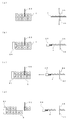
- FIG. 12 is a schematic side view showing a payout operation for paying out a straight blister package for fractions from a cassette by the pressing portion of FIG. 11.
- FIG. 12 is a schematic side view showing a payout operation for paying out the blister package for fractions curved from the cassette by the pressing portion of FIG. 11. It is explanatory drawing which shows an example of the cutting method of the fraction by the cutting member shown in FIG.
- FIG. 21 is an expansion perspective view which shows the state which looked at the head part of the cassette of FIG. 21 from a different angle. It is a perspective view which shows the extrusion member of FIG. It is a perspective view which shows the state which removed a part of cassette from FIG. It is an expansion perspective view of the head part of the cassette of FIG.
- FIG. 22 is an enlarged side view of the leading portion of the cassette of FIG. 21.
- FIG. 21 is an enlarged partially exploded perspective view showing a pressing unit in FIG. 20. It is a perspective view which shows the state which looked at the press part of FIG. 20 from the other side.
- FIG. 28 is a partially exploded view showing a roller portion of the pressing portion in FIG. 27.
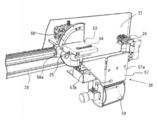
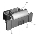
- FIG. 1 is a schematic perspective view of a medicine dispensing apparatus according to the present embodiment
- FIG. 2 is a view showing a state where an exterior panel 6 is removed.
- a medicine dispensing apparatus a plurality of cassettes 2 serving as storage containers are mounted in a lattice pattern without gaps on the apparatus main body 1, and a blister package 4 in which a plurality of medicines are packaged from each cassette 2 by a dispensing member 3 (FIG. 12). Reference) is paid out sequentially.
- the series of blister package 4 dispensing processes is executed by the control member 100 (see FIG. 15) based on prescription data input from a host computer (not shown) or the like. *
- the device main body 1 has a substantially rectangular parallelepiped shape by attaching an exterior panel 6 around the frame body 5.
- a transport device 7 for transporting a tray that is not to be transported is provided, and an upper region of the rear half is a cassette mounting portion 8.
- a roller conveyor is used as the conveying device 7, but various conveying means such as a belt conveyor and a pusher can be used.
- the cassette mounting portion 8 is provided with mounting members 8b on the opposing surface 8a of the support panel arranged at a predetermined interval in the left-right direction, and is configured so that the cassette 2 can be inserted into the mounting member 8b and mounted.
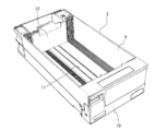
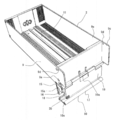
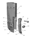
- the cassette 2 includes a substantially rectangular parallelepiped cassette body 9 having an open top surface and an opening / closing door 10 disposed on the front surface of the cassette body 9. Prepare. *
- a guide groove 11 is formed on the bottom surface of the cassette body 9.
- An extrusion member 12 is disposed in the cassette body 9 so as to be capable of reciprocating along the guide groove 11. Further, the pushing member 12 can urge the blister package 4 accommodated in the cassette body 9 with a constant load toward the door 10 regardless of the position of the pushing member 12 by a constant load spring (Conston) not shown. It has become. *
- an outlet 13 is formed at the front end of the bottom surface of the cassette body 9 so that the leading blister package 4 can be taken out.
- a part of the outlet 13 is closed by a closing piece (not shown) rotatably provided at the center of the front end of the bottom surface, and the leading blister package 4 is prevented from dropping.
- the closing piece is biased in the closing direction by a spring (not shown).
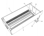
- the front plate 9 a of the cassette body 9 is formed with a recess 14 that extends vertically in the central portion on the inner surface side.
- the recess 14 is a relief for allowing the pressing portion 30 to move when the leading blister package 4 is taken out.
- the front plate 9a of the cassette body 9 faces the innermost side both sides (both sides of the recess 14 shown in FIG. It is preferable to form a concave curved surface 9b.
- the contact position with the front plate 9a can be set to the front side by the curved surface 9b. That is, even if the blister package 4 is curved, the position of the upper edge can be corrected so as not to be far from the front plate 9a. Therefore, even the blister package 4 that is curved can be smoothly pushed down by the pressing portion 30 of the payout member 3 described later.
- the guide plate 48 includes a first curved surface 49a that gradually protrudes upward toward the front plate 9a. Further, a second curved surface 49b (guide surface) formed in a convex shape is provided at the tip portion from the first curved portion 49a. The second curved surface 49b guides the blister package 4 slidably contacting the outlet to the outlet 13, and applies a force in a direction that is straight if the blister package 4 is curved in the short direction. .
- the position of the guide plate 48 can be adjusted in the width direction (the direction perpendicular to the paper surface in FIG. 12A).
- the guide plate 48 can be positioned between the plurality of pocket portions for storing the medicines of the blister package 4.
- the guide plate 48 is attached to the front plate 9a with a slight gap through which only one sheet portion of the blister package 4 (a flat portion to which a cover film is attached as described later) can pass. It has been. Thereby, the lower edge part of the blister package 4 located in the vicinity of the outlet 13 can be reliably supported, and it is prevented that the blister package 4 overlaps and is discharged or clogged. Further, the closing piece or the like can be eliminated.
- both side surfaces of the cassette body 9 have guide surface portions 9 c that protrude further forward from the front surface.
- Each guide surface portion 9c is formed with a locking hole 9d at an opposing position, and a locking projection (not shown) attached to the recess 10a of the open / close door 10 can be engaged and disengaged.
- a locking projection (not shown) is locked in the locking hole 9d, and the opening / closing door 10 can be positioned in the closed position.
- a guide hole 9e is formed in one guide surface portion 9c, and a guide pin 46 of a drive mechanism 37 described later can be engaged and disengaged.
- a plurality of blister packs 4 (PTP (Press Through Package) sheets) are stacked and accommodated horizontally in the cassette body 9.
- the blister pack 4 has a plurality of pockets for storing the medicine, and a cover film is attached so as to close the pockets.
- the stacking direction of the blister package 4 is set so that the cover film side faces the front side of the cassette body 9.
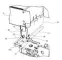
- the open / close door 10 is attached to the lower front end of the cassette body 9 so as to be rotatable about a support shaft 10 a.
- the open / close door 10 includes a bearing portion 15 that is rotatably attached to the support shaft 10 a, a front surface portion 16 that extends from the bearing portion 15, and a guide receiving portion 17 that protrudes from the front end edge of the front surface portion 16 in a right angle direction. Become. *
- the bearing portion 15 is integrated with an end surface 15b formed with an operation hole 15a in which a rotation pin 43 of the payout member 3 described later is engaged and disengaged on one end side thereof.
- the front surface portion 16 has a flat plate shape, and a notch portion 18 is formed in the central portion of one side edge thereof. Using this notch 18, it is possible to grip the fraction of the blister package 4 by a grip member 24 described later.
- the guide receiving portion 17 has a reference surface 17a on which the side edge portion (lower edge portion) of the fraction (residue) of the blister package 4 is abutted and positioned.
- the leading edge of the guide receiving portion 17 bent into a U shape is formed in a circular cross section, and recessed portions 10a are formed at both ends thereof, respectively, and when the open / close door 10 is positioned at the closed position, A locking projection (not shown) that is locked to the locking hole 9b of the guide surface 9a is provided.
- the open / close door 10 is rotated 180 degrees from the normal payout position (FIG. 3) in which the rotation pin 43 of the payout member 3 is engaged with the operation hole 15a and turned to the front end side of the cassette body 9, and the closed position. Positioning is possible at the fraction payout position (FIG. 4).
- the blister package 4 is positioned with respect to the reference surface 17a by bringing the lower edge of the blister package 4 into contact with the reference surface 17a.
- a holding piece 19 is rotatably attached to the support shaft 10a.
- the holding piece 19 is urged toward the front face 16 side (shown in the direction of arrow a in FIG. 6) by a coil spring (not shown) attached to the support shaft 10a.
- the holding piece 19 is integrated with a sucked portion 20 made of a magnetic material at a lower end portion on one end side.
- the attracted portion 20 is attracted by a magnet 52 (see FIG. 7), which will be described later, the holding piece 19 rotates in the direction of the arrow b in FIG.
- the holding state of the blister package 4 is released.
- the blister package 4 is positioned in the vertical direction by bringing its lower edge portion into contact with the reference surface 17a.
- a magnetic part and a light emitting part are provided on the front surface of the cassette.
- This magnetic part is attracted to an electromagnet part (not shown) provided on the support plate 21 side described later when the cassette 2 is pulled out from the cassette mounting part 8.
- the light emitting unit is irradiated with light from an LED (not shown) provided on the apparatus main body 1 side.
- the light emitting unit is irradiated with the LED when, for example, a chemical shortage or abnormality is notified. According to this, it is possible to eliminate the need for electrical components and wiring on the cassette 2 side, and it is possible to simplify the configuration and manufacture at a low cost.
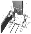
- the dispensing member 3 includes a support plate 21, a first dispensing member 22, a second dispensing member 23, a gripping member 24, a cutting member 25, and A recovery member 26 is provided.
- the support plate 21 is provided so as to be able to reciprocate on a horizontal rail 28 that can be raised and lowered with respect to a vertical rail 27 arranged on the front left and right of the apparatus main body 1.
- the first payout member 22 meshes with the rack 29 through a gear 22 b provided on the rotation shaft of the motor 22 a and drives the motor 39 to rotate forward and reverse, thereby causing the rack 29 to be interposed via the arm portion 31.
- the integrated pressing unit 30 is moved up and down.
- the pressing portion 30 extends downward with its upper end screwed to the tip of an arm portion 31 extending in the horizontal direction from the rack 29. As shown in FIGS. 11 and 12, the pressing portion 30 has a back surface portion 33 integrated with the back surface of the front plate 32. A gap is formed between the front plate 32 and the back surface portion 33, and elastic pieces 34 are fixed to the upper portions on both sides. In the back surface portion 33, the lower end positions of both side portions are positioned higher than the lower end position of the front plate 32, and the lower end portion of the elastic piece 34 is exposed there.
- the elastic piece 34 includes a linear portion 34a that gradually inclines toward the back portion 33 as it goes downward from the fixed position, and a curved portion 34b that curves toward the front plate 32 at a portion exposed downward from the back portion 33. It consists of A locking piece 35 protrudes from the curved portion 34b.
- the locking piece 35 may be formed by cutting and raising a part of the elastic piece 34, or may be formed by separately integrating small pieces by adhesion or the like.
- the curved portion 34b and the locking piece 35 constitute a guide portion 36. As will be described later, the guide portion 36 is used to reliably guide and push down the upper edge of the blister package 4 regardless of the curved state of the blister package 4.
- the blister package 4 when the blister package 4 is deformed so that the side edge portion is curved toward the elastic piece 34, the blister package 4 is pressed by the elastic piece 34 so as to suppress deformation. be able to.
- the protruding dimension of the locking piece 35 from the curved portion 34 b is substantially the same as the thickness of the sheet portion of the blister package 4.
- the second payout member 23 includes an electromagnet part (not shown) and a drive mechanism 37 as shown in FIG. *
- the electromagnet portion is excited by energization, attracts the magnetic portion of the cassette 2 at the forward position, and retracts the cassette 2 from the cassette mounting portion 8 to the medicine extraction position by moving backward.
- the drive mechanism 37 is configured to transmit the driving force of the motor 39 provided on the mounting plate 38 having a substantially L-shaped cross section to the rotation pin 43 through a gear, and slides in the width direction according to the size of the cassette 2. It is possible. Here, three guide positions corresponding to three types of cassettes 2 of different sizes can be positioned at one guide position and one retracted position. *
- the details of the drive mechanism 37 are as follows. That is, a drive gear 40 is provided on the rotating shaft of the motor 39, an intermediate gear 41 is engaged with the drive gear 40, and a driven gear 42 is engaged with the intermediate gear 41.
- a driven plate 44 having a rotation pin 43 is integrated with the end face of the driven gear 42.
- the pivot pin 43 can be engaged and disengaged with an operation hole 15 a formed in the bearing portion 15 of the opening / closing door 10 at the tip end portion.
- the mounting plate 38 is integrated with a guide pin 46 that is positioned in the guide hole 9 e of the cassette body 9. The distal end of the guide pin 46 is formed in a conical shape, so that it can easily enter the guide hole 9e.
- the driven plate 44 that is, the rotation pin 43 rotates via the gear. Move. Thereby, the open / close door 10 is rotated to the normal payout position and the fraction payout position around the support shaft 10a while being positioned by the guide pin 46. It is preferable to provide a torque limiter or the like in any of the power transmission paths from the motor 39 to the driven plate 44 (for example, on the rotating shaft of the driven gear 42). As a result, when the door 10 is rotated to the closed position by the drive mechanism 37, a load more than necessary does not act on the cassette body 9 side, and damage can be prevented. *
- the grip member 24 includes a pair of grip pieces 47.
- the grip piece 47 is provided in the front portion of the support plate 21 so as to be reciprocally movable in the horizontal direction.
- a rack (not shown) formed on the opposing surface of an arm 47a (one not shown) extending from each gripping piece 47 via a pinion (not shown) provided on the rotation shaft of the motor 24a. It is opened and closed by being transmitted to (not shown). Further, one end portion (free end portion) of each gripping piece 47 is bent in a crank shape to constitute a gripping portion 50 facing each other.
- Through-holes are respectively formed in the gripping portions 50, and it is possible to detect whether or not the blister package 4 is sandwiched through the through-holes by an optical sensor 51 provided on one gripping piece 47.
- One grip piece 47 is provided with a magnet 52 (here, a neodymium magnet is used). The magnet 52 is for attracting the attracted portion 20 provided on the holding piece 19 of the opening / closing door 10 and rotating the holding piece 19 to separate it from the front face portion 16. *
- the cutting member 25 is obtained by attaching a pair of cutting blades 55 (see FIG. 14) that can be brought into and out of contact with a support base 53 with a gap 54 interposed therebetween.
- One end surface of the support base 53 is fixed to a fan-shaped rotation plate 56 that is a position adjusting member.
- the rotation plate 56 has a gear formed on the outer peripheral edge. The gear meshes with a gear provided on the rotating shaft of the motor 56a. Then, by driving the motor 56a, the rotating plate 56 rotates forward and backward via the gear. Thereby, the cutting blade 55 rotates with the rotation plate 56, and the cutting position with respect to the blister package 4 grasped by the grasping member 24 is changed.
- the cutting member 25 is positioned and used at two positions, a horizontal position (FIG. 9) and a vertical position. Moreover, the cutting member 25 is provided with an elevating mechanism (not shown) so that the cutting position by the cutting blade 55 can be adjusted. Thereby, it is possible to cut
- a holding member (not shown) for preventing the positional shift of the blister package 4 inserted in the gap of the support base 53 is provided, and the positional shift (jumping etc.) of the blister package 4 due to the impact at the time of cutting is provided. It is preferable to prevent. *
- the collection member 26 includes a guide passage 57 and a collection container 58.
- the guide passage 57 includes a straight portion 57a and an inclined portion 57b.
- the blister package 4 that falls from the outlet 13 of the cassette 2 passes through the straight portion 52a, and the inclined portion 52b is cut by the cutting member 25.
- the blister package 4 of the other fraction passes and joins the straight part 52a.
- the collection container 58 has three storage parts (not shown), and the blister package 4 supplied through the guide passage 57 is divided into compartments in a tray (not shown) that is conveyed by the conveying device 7. Transport to. *
- step S1 If prescription data is input from a host computer (not shown) or the like (step S1), the dispensing member 3 is moved to the cassette 2 in which the blister pack 4 of the corresponding medicine is stored based on the input prescription data (step S1). Step S2). Then, it is determined whether or not the blister package 4 is to be paid out as a whole sheet (step S3). This determination may be made based on whether or not the number of drugs included in the prescription data is larger than the number of drugs per sheet of the blister package 4. At this time, the number of blister packs 4 to be paid out is calculated. This operation may be determined by how many times the former quantity is greater than the latter quantity. When a plurality of blister packs 4 are paid out, the surplus number is paid out in the processing after step S10 described later. *
- step S3 When paying out the blister package 4 as a whole (step S3: YES), the support plate 21 is moved to excite the electromagnet portion. Thereby, since the magnetic part of the cassette 2 is attracted
- the blister package 4 is often delivered in a state where a plurality of blister packs 4 are bundled with rubber bands or the like. For this reason, the blister package 4 may be bent in the short direction with respect to the vertical plane in a state where it is set in the cassette body 9.
- the pressing portion 30 has the guide portion 36 formed at the lower end portion of the elastic piece 34. Therefore, even if the blister package 4 to be pushed down is curved as shown in FIG. 13A, when the pressing portion 30 is moved downward, the blister package 4 is changed from FIG. 13B to FIG. 13C. As shown in FIG. 4, the upper edge portion of the leading blister package 4 can always be guided by the guide portion 36.
- the blister package 4 is urged in the direction in which the curved shape is corrected by the elastic force of the elastic piece 34. Therefore, even the blister package 4 that is curved can be smoothly discharged from the cassette 2 through the outlet 13.
- the discharged blister package 4 is collected into the collection container 58 through the guide passage 57.
- the pressing unit 30 raises the next blister package 4 in order to push it down (step S6).
- step S7 it is determined whether or not the number of blister packs 4 to be paid out as a whole sheet has reached a predetermined number calculated based on the prescription data (step S7). If the predetermined number has not been reached, the process returns to step S5 to repeat the pressing operation for lowering the pressing unit 30 (step S5) and the returning operation for increasing (step S6). If the predetermined number has been reached, it is determined that the delivery of the blister package 4 has been completed, and the electromagnet part is advanced to accommodate the cassette 2 in the cassette mounting part 8 (step S8). Then, the collection container 58 (dispensing member 3) is moved to a tray (not shown) (step S9). *
- step S3 NO
- the opening / closing door 10 is rotated 180 degrees by the rotation pin 43 and positioned at the fraction discharge position (step S10). Then, it is determined whether or not the fractional blister package 4 is held by the open / close door 10 (fractional holding?) (Step S11). *
- step S11 If the blister package 4 of the fraction is not held on the opening / closing door 10 (step S11: YES), the blister package 4 positioned at the head is pushed down by the pressing unit 30 in the same manner as described above and discharged through the outlet 13. (Step S12). The discharged blister package 4 is sandwiched between the front plate 32 and the holding piece 19 by the holding piece 19 biased toward the front plate 32 by the coil spring.
- step S13 If the fractional blister package 4 is held in the open / close door 10, it is determined whether or not the quantity N1 of the medicine is equal to or greater than the quantity N2 desired to be dispensed in the prescription data (step S13). If N1 ⁇ N2, steps S16 to S30 described later are executed. If N1 ⁇ N2, the fractional blister package 4 is gripped by the gripping member 24 and dispensed to the collection container 58 (step S14), and the remaining fraction is calculated (step S15). Steps S16 to S30 described later are executed for the minute.
- the holding member 24 When paying out the fraction, the holding member 24 is brought close to the door 10 (step S16). Then, when the grip piece 47 is separated and the blister package 4 is moved to a position where it can be gripped, the magnet 52 provided in the vicinity of the grip member 24 sucks the sucked portion 20 provided on the holding piece 19, and FIG. As shown, the holding piece 19 rotates in a direction away from the front surface portion 16. The blister package 4 loses its holding by the holding piece 19 and falls until its lower edge is brought into contact with the guide receiving portion 17. Thereby, the blister package 4 can be always positioned at the same position in the vertical direction with respect to the reference surface 17a of the guide receiving portion 17 of the door 10.
- the blister package 4 can always be positioned immediately before the blister package 4 is gripped by the gripping member 24.
- the timing of the rotation of the holding piece 19 by the magnet 52 is not particularly limited, for example, after the cutting by the cutting member 25.
- the blister package 4 is discharged vertically downward through the outlet 13 of the cassette 2 by the pressing portion 30, the blister package 4 is hardly displaced in the horizontal direction.
- the gripping member 24 is driven, and the ear portion of the blister package 4 is gripped by the gripping piece 47 through the notch 18 formed in the guide receiving portion 17 (step S17). At this time, the ear portion of the blister package 4 is detected based on the detection signal from the optical sensor 51, and it is confirmed that the blister package 4 is securely held by the holding piece 47. Then, the gripping member 24 is moved horizontally to the cutting position of the cutting member 25 (step S18). In the cutting member 25, a rotation position is changed according to the fraction of the blister package 4. *
- step S19 When the pocket part of the blister package 4 is an even number row (2 rows or 4 rows), it is determined whether or not the fraction is an even number (step S19). If the fraction is an even number (step S19: YES), the cutting member 25 is set to a vertical position rotated 90 degrees (step S20), and the portion to be cut off by adjusting the position of the gripping member 24 is a desired quantity. Positioning is performed (step S21). Thus, when the blister package 4 is cut in the lateral direction by the cutting member 25 (step S22), the desired fraction is collected into the collection container 58 through the guide passage 57. *
- step S15 If the fraction is an odd number (step S15: NO), the blister package 4 is cut in the horizontal direction as described above (steps S23 to S25), and then the remaining one from the remaining blister package 4 is cut. .
- the rotating plate 56 is rotated 90 degrees to the horizontal position (step S27), and only half is further cut. What is necessary is just to cut
- the cutting blade 55 is once opened by a predetermined dimension as shown in FIG. 14B (step S29).
- the open dimension at this time is such that the interval between the cutting blades 55 is wider than the thickness of the sheet portion of the blister package 4 and does not exceed the entire thickness including the pocket portion.
- FIGS. 14C to 14D when the gripping member 24 is moved in the horizontal direction (step S30), it is forcibly even if it is not successfully separated at the boundary portion of the cut portion. It becomes possible to separate.
- FIG. 14 although it is explanatory drawing in the case of cut
- the remaining blister package 4 with the fractions cut in this way is moved to the guide receiving portion 17 of the door 10 by moving the gripping member 24 (step S31). And the remaining blister package 4 is clamped with the holding piece 19 provided in the guide receiving part 17 by canceling
- the holding piece 19 of the door 10 is separated from the front surface portion 16 by the action of the magnet 52, and a gap is formed. Therefore, the blister package 4 can be smoothly positioned between the front surface portion 16 and the holding piece 19 simply by moving the gripping member 24.
- the holding piece 19 is rotated by the biasing force of the coil spring, and the blister package 4 is sandwiched between the front surface portion 16. can do. Further, if the blister package 4 is sandwiched, the support position by the holding piece 19 is stored as coordinate data together with the remaining quantity (number of pockets), and the gripping member is based on this data at the next dispensing. What is necessary is just to move 24 and pay out the remaining blister package 4. Then, if there is no remaining blister package 4 held in the guide receiver 17, the new blister package 4 is discharged from the cassette 2 to the guide receiver 17 and cut in the same manner as described above. That's fine. *
- the pushing direction by the pressing unit 30 is not limited to the vertically downward direction, and may be a horizontal direction.
- the extrusion direction of the blister package 4 is not limited to the short direction, and may be the longitudinal direction.
- the ear portion of the blister package 4 (a flat plate portion separable from the pocket portion side) may be positioned on the lower side.
- the accommodating direction of the blister package 4 is rotated by 90 degrees, and the longitudinal direction thereof is directed in the vertical direction. What is necessary is just to push down, and the press part 30 may be rotated 90 degree
- the cutting method is not limited to this.
- two medicines are cut from two rows of blister packs 4, it is possible to cut two medicines from one row as shown in FIG. *
- FIG. 18 it is good also as a structure which can pay out two blister package bodies 4 simultaneously.
- the protruding sides of the tablet accommodating portion of the blister package 4 are brought into contact with each other.
- the two blister packs 4 can be easily transferred together.
- the blister package 4 is contained in a box in such a state that the two blisters are joined together. For this reason, it is possible to take out the blister package 4 from the delivered box and set it as it is.
- the push-down unit 30 only needs to be configured to be able to push down the two blister packages 4 by the bottom surface.
- the push-down portion 30 is formed in a flat plate shape so that the overlapped pocket portion is pushed down on the bottom surface thereof.
- interval of the taking-out port 13 of the cassette 2 be a value which the two blister package bodies 4 can pass. Accordingly, when the pressing portion 30 is moved downward from the state shown in FIG. 18A, the two blister packs 4 are pushed down on the bottom surface, and are discharged from the outlet 13 as shown in FIG. 18B. Is done. Then, as shown in FIG.
- the holding piece 19 is rotated in a non-contact manner by the attractive force of the magnet 52 provided on the gripping member 24 as the operating portion. It is also possible to have a configuration in which the lens is directly abutted on and rotated. Moreover, although the plate-shaped holding piece 19 was used as a holding
- the position of the cutting member 25 relative to the blister package 4 gripped by the gripping member 24 is changed by rotating the rotating plate 56.
- the position of the blister package 4 gripped by the gripping member 24 relative to the cutting member 25 may be changed by rotating the gripping member 24 or by rotating both the cutting member 25 and the gripping member 24.
- the pressing unit 30 can be configured as follows. *
- a plate member and an urging member for urging the plate member may be provided instead of the elastic piece 34.
- the plate material is preferably made of resin, but may be made of metal or the like.
- various things, such as urethane rubber and a coil spring, can be used for a biasing member. By comprising the plate material and the urging member, the durability can be improved as compared with the case of using a leaf spring.
- the payout member 3 may be configured by a roller member instead of the holding piece 19 formed by a leaf spring.
- a roller member 60 in which a rubber roller is integrated around a rotation shaft and can be driven to rotate can be used.
- a notch 61 (or an opening) is formed in the front plate 9 a of the cassette body 9 in the vertical direction, and the roller member 60 is pressed against the blister package 4 positioned at the head via the notch 61. Then, by rotating the roller member 60, the blister package 4 is discharged downward through the outlet 13.
- the blister package 4 of the fraction is held by the guide receiving portion 17 with the door 10 being rotated 180 degrees. It is good also as just forming the accommodating part which can accommodate the blister package 4 of a fraction, without making it move.
- the blister package 4 may be transferred to the housing portion by the gripping member 24.
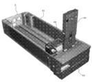
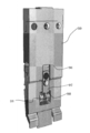
- the cassette 2 and the pressing unit 30 may be configured as shown in FIGS. *
- the cassette 2 includes a cassette body 61 and an opening / closing door 62 as in the first embodiment.
- the cassette body 61 includes a pair of presser pieces (first presser piece 63 and second presser piece 64) that protrude from both sides of the upper end of the front plate 61 a into the cassette main body 61, and each presser.
- Guide portions 65a and 65b disposed inside the pieces 63 and 64, respectively.
- one guide part 65a is arrange
- the first presser piece 63 includes a first horizontal portion 63a that protrudes in the horizontal direction toward the inside of the cassette body 61, and a second horizontal portion that extends in the horizontal direction at a tip portion thereof obliquely downward from the first horizontal portion 63a.
- the second presser piece 64 includes a first horizontal portion 64a and a second horizontal portion 64b similar to the first presser piece 63, and the guide portion 64c is configured only by an inclined portion extending obliquely upward.
- the guide portions 65a and 65b have rear surfaces fixed to the front plate 61a, and have a curved surface 65c (see FIG. 24) similar to that of the first embodiment on the front surface, and guide the curved blister package 4. *
- an extrusion member 66 is arranged so as to be movable in the front-rear direction.
- the pushing member 66 has substantially the same configuration as that of the first embodiment, but differs in the following points.
- the extrusion member 66 is provided with an extrusion plate 67 extending in the width direction of the cassette body 61 on the front side for pushing the blister package 4, and is made of a material having a large friction coefficient (for example, urethane rubber) at both ends thereof.
- An extrusion pad 68 is attached. The extrusion pad 68 is in pressure contact with the blister package 4 and prevents its displacement. In particular, when the remaining amount of the blister package 4 in the cassette body 61 becomes two sheets, when the first sheet is dispensed, the second sheet is effectively prevented from being dispensed together.
- a support plate 69 extending in the width direction is disposed on the bottom surface side of the cassette body 61, and a pair of guide plates 70 are attached thereto at a predetermined interval.
- a long hole 69 a is formed in the support plate 69 so that the mounting position of each guide plate 70 can be adjusted in the width direction of the cassette body 61.
- the position of each guide plate 70 can be adjusted according to the width dimension of the blister package 4 that differs depending on the medicine, and the blister package 4 can be guided between the guide plates 70 (in detail, the blister The sheet portion of the package 4 is guided by the guide plate 70).
- Each guide plate 70 includes a mounting base 71 positioned on the support plate 69 and a guide piece 72 extending therefrom.
- the guide piece 72 includes a first bending portion 73 that gradually curves upward toward the tip, an inclined portion 74 that is formed at the tip portion and is cut obliquely downward, and the inclined portion 74.
- the second bending portion 75 extends downward.
- the second curved portion 75 gradually protrudes forward (front plate 61a side) toward the lower end, and at the closest position, only the sheet portion of the blister package 4 can pass through the gap with the front plate 61a. It is a dimension. Accordingly, when the first blister package 4 is discharged from the cassette body 61, it is possible to prevent the second blister package 4 from being discharged together.
- a ridge member 76 is provided on the front surface of the cassette body 61 as shown in FIGS.
- the ridge member 76 has a cylindrical shape, and the protruding surface is a curved surface having an arcuate cross section.
- the protruding member 76 is made of an elastic material such as synthetic rubber, and can be pressed against the blister package 4.
- the open / close door 62 includes a front surface portion 77 and a guide receiving portion 78 extending in a direction perpendicular to the front edge of the front surface portion 77, as in the first embodiment.
- a groove portion 79 is formed on the inner surface of the front surface portion 77 along the guide receiving portion 78, and a protrusion 81 is formed on the opposite side of the notch portion 80 in the vicinity of the groove portion 79.
- the open / close door 62 includes a holding piece 82.
- the holding piece 82 is formed by processing a synthetic resin material into a rectangular plate shape in plan view.
- bearing portions 83 On one long side (side edge portion) of the holding piece 82, bearing portions 83 having a substantially C-shaped cross section are formed at two locations.
- the holding piece 82 is rotatably mounted by elastically deforming the bearing portion 83 and rotatably mounting it on a support shaft 84 provided at the lower end portion of the front surface portion 77.
- Three sides of the holding piece 82 excluding the side edge portion where the bearing portion 83 is formed protrude, and a recess 85 is formed inside thereof.
- a part of a spring 86 attached to the support shaft 84 is locked between the bearings 83 at the central portion of the recess 85.
- the holding piece 82 press-contacts the front-surface part 77 of the opening-and-closing door 62, and the blister package 4 can be hold
- a guide guide portion 87 is formed at a corner portion on one end side of the holding piece 82.
- the guide guide portion 87 is configured by a curved surface that gradually bulges toward the front surface portion 77 side from a circular arc edge in a plan view arc shape.
- a suction plate 88 made of a magnetic material is attached to a corner portion on the other end side of the holding piece 82.
- the pressing unit 30 includes a main body plate 89, pressing pieces 90 provided on both side portions on the lower side of the main body plate 89, and a roller portion 91 provided on the lower center portion of the main body plate 89.
- the main body plate 89 has a flat rear surface, and a protrusion 92 is formed on the front surface by forming depressions on both sides except for the upper end portion. .
- the protruding portion 92 is formed with a thick portion 93 having a large thickness at the central portion, and an inclined portion 94 is formed so that the lower portion thereof is gradually inclined to the back surface side toward the lower end. The tip of the inclined portion 94 protrudes further from the lower end of the main body plate 89.
- the thick portion 93 is formed with a rectangular opening 95 that communicates the front and back surfaces of the main body plate 89. Further, as shown in FIG.
- a concave portion 96 extending vertically is formed in the center of the back surface of the main body plate 89, and a locking piece 97 is fixed thereto.
- the locking piece 97 projects a narrow locking portion 98 from the lower end, and the locking portion 98 can be locked to each gear 106 of the locking gear portion 103 of the roller portion 91 described later.
- the pressing piece 90 is composed of a strip-shaped plate material made of a synthetic resin material. Each pressing piece 90 is disposed in a recessed portion formed on both sides of the protrusion 92 of the main body plate 89. Each pressing piece 90 is supported by the upper part of the protrusion 92 so as to be rotatable about the support shaft 99, and is urged forward by a spring 100 (not shown). The recessed part in which the one end side of this is arrange
- a protrusion 92a that protrudes from the protrusion 92 is positioned in one recess 101a (on the protrusion 92 side), and the rotation range of the pressing piece 90 is restricted.
- the other concave portion 101b is for making the left and right pressing pieces 90 a common component.
- the lower end portion of each pressing piece 90 includes a locking piece 90a and a thin portion 102 that gradually bends toward the back surface and further has a tip portion extending downward.
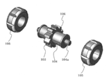
- the roller portion 91 includes a cylindrical body 104 having a locking gear portion 103 on the outer peripheral surface, and a pair of rotating rollers 105 disposed on both sides of the locking gear portion 103. Yes.
- the roller portion 91 is disposed in an opening 95 formed in the protruding portion 92 of the main body plate 89, and the cylindrical body 104 is rotatably supported on a support shaft 104a provided therein.
- the locking gear portion 103 includes a plurality of gears 106 that are inclined toward one side in the circumferential direction of the cylindrical body 104.
- a locking portion 98 of a locking piece 97 provided on the main body plate 89 is locked to each gear 106, and the roller portion 91 can be rotated only in one circumferential direction (the same function as a one-way clutch is performed). .)
- the rotating roller 105 is attached to the outer periphery of the cylindrical body 104 so as to be integrally rotatable. However, when a force more than necessary is applied, the position with respect to the cylindrical body 104 is shifted and idles. Here, the force acting on the rotating roller 105 during idling is set so as not to damage the blister package 4 with which the rotating roller 105 contacts.
- the rotation roller 105 is in contact with the next (second) blister package 4, and the rotation roller 105 rolls on the plane of the second blister package 4. For this reason, although the pressing part 30 is lowered, it is difficult for a downward force to act on the second blister package 4. Further, the gap formed between the guide plate 70 and the front plate is set to a value that allows only one blister package 4 to pass through, as described above. Therefore, the second blister package 4 is difficult to move downward together with the first blister package 4 being pushed down, and is not discharged from the opening 95. *
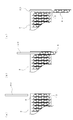
- the blister package 4 in the cassette body 61 is moved forward by the pushing member 66.
- the blister package 4 on the leading side moves its lower edge along the first curved portion 73 of the guide piece 72 and is displaced in the vertical direction between the blister packages 4.
- only the first blister package 4 at the top gets over the first curved portion 73, reaches the inclined portion 74, and moves to the second curved portion 75.
- the first first sheet Only moves to a position where it can be paid out from the cassette body 61.
- the blister package 4 passes the 2nd curved surface 75, it curves to the opposite side to the curved surface 65c, and is corrected so that a curved shape may become flat.
- the positional relationship between the guide plate 65 and the guide piece 72 is set so that the blister package 4 cannot pass unless the sheet portion is curved. That is, as shown in FIG. 25, the inner lower end position of the guide plate 65 and the boundary position between the inclined portion 74 of the guide piece 72 and the second bending portion 75 are arranged to overlap each other.
- the blister package 4 is prevented from being discharged unless it is pushed down by the push-down unit 30. Further, even when the blister pack 4 is pushed down by the push-down unit 30, simultaneous discharge (double feed) of the two blister packs 4 is prevented.
- the pressing unit 30 is moved up and down to pay out the necessary number of blister packs 4. *
- the open / close door 62 When the fraction of the blister package 4 is dispensed from the cassette 2, the open / close door 62 is opened and is positioned at the fraction dispensing position. If there is no blister package 4 held by the open / close door 62, the open / close door 62 is positioned at the fraction payout position for only one blister package 4 from the cassette body 61 by lowering the pressing portion 30 in the same manner as described above. Supply in. In the open / close door 62, the holding piece 82 is biased toward the front surface portion 77. Therefore, the supplied blister package 4 is sandwiched between the holding piece 82 and the front surface portion 77 of the open / close door 62. A guide guide portion 87 is formed at the corner of the holding piece 82 and the holding range of the blister package 4 is narrow.
- a protrusion 81 is formed on the front surface portion 77 and is held between the holding piece 82 and the holding piece 82.
- the pressure is increased. Therefore, although the clamping range is narrow, the clamping state of the blister package 4 is almost the same as the other parts. As a result, the blister package 4 is appropriately held without being inclined between the holding piece 82 and the front surface portion 77.
- the blister package 4 held between the holding piece 82 and the front surface portion 77 drives the gripping member 24 and moves it to the side opposite to the cutout portion 80 to cut the cutting member.
- the fraction is cut by 25 and paid out.
- the blister package 4 that has been cut in fractions is moved to the original position by the gripping member 24.
- the blister package 4 is deformed or tilted with respect to the gripping member 24 when cutting the fraction, but since the guide piece 87 is formed on the holding piece 82, the holding piece 82 and the front face 77 Move smoothly between.
- the open / close door 62 is rotated from the fraction dispensing position to the closed position.
- the protruding member 76 provided in the cassette body 61 is pressed against the fractional blister package 4, and the blister package 4 is sandwiched between the open / close door 62.
- the blister package 4 has one row of pocket portions positioned in the groove portion 79 of the opening / closing door 62, where displacement in the width direction is prevented. For this reason, the state which moved the opening-and-closing door 62 to the closed position, and the holding
- the medicine dispensing device can be configured as follows. That is, the medicine dispensing device is provided in a state in which the apparatus main body, a plurality of blister packaging bodies in which the medicines are individually packaged are stacked, and the apparatus main body are movably provided and moved to the container And a payout member for paying out the blister package accommodated, and the payout member rotates in contact with the next blister pack when the blister pack is taken out from the outlet of the containing container. It is set as the structure provided with the roller part. *
- the discharging member includes a lock mechanism that prevents rotation of a roller portion that contacts the next blister package when the blister package is removed from the outlet of the storage container and then moved in a direction opposite to the removal direction. It is preferable to provide.
- the medicine dispensing device is provided in a state where the device main body, a plurality of blister packaging bodies in which the medicines are individually packaged are stacked, and the device main body are movably provided and moved to the container And a discharging member for discharging the stored blister package, and the storage container has an outlet formed in a direction perpendicular to the pressing direction with respect to the blister package pressed toward the one end side.
- a guide plate that guides a side edge of the blister package in the vicinity of the outlet, and the guide plate gradually moves in a direction opposite to the outlet as the blister package is pressed. It is configured to include a bending portion that changes the guide position and an inclined portion that is continuous with the bending portion and is inclined toward the outlet side.
- the medicine dispensing device is provided in a state where the device main body, a plurality of blister packaging bodies in which the medicines are individually packaged are stacked, and the device main body are movably provided and moved to the container And a discharge member for discharging the stored blister package, wherein the storage container allows the blister package to be discharged from the outlet, and the blister package discharged from the outlet
- An openable / closable door is provided at a fraction dispensing position that can hold the body, and the open / close door presses the blister package that has been dispensed from the outlet at a part dispensing position at the fraction dispensing position.
- a holding piece for holding, and the holding piece is gradually moved away from the blister package toward the direction of carrying out the blister package at a position where the blister package is taken in and out. It is obtained by a structure formed having a leading guide portion to be. *
- the storage container includes a guide portion that presses and positions the held blister package when the opening / closing door rotates to the payout position.
- the opening / closing door has a recess formed at a position facing the guide portion when the opening / closing door rotates to the payout position.
- Second payout member 24 ... Grip member 25 ... Cutting member 26 ... Collection member 27 ... Vertical rail 28 ... Horizontal rail 29 ... Rack 30 ... Push-down part 31 ... Arm part 32 ... Front plate 33 ... Back part 34 ... Elastic piece 35 ... Locking piece 36 ... Guide part 37 ... Drive mechanism 38 ... Mounting plate 39 ... Motor 40 ... Drive gear 41 ... Intermediate gear 42 ... Driven gear 43 ... Rotating pin 44 ... Driven Plate 45 ... Operating hole 46 ... Guide pin 47 ... Grip piece 48 ... Guide plate 49a ... First curved surface 49b ... Second curved surface 50 ... Grip portion 51 ... Photo sensor 52 ... Magnet 53 ... Support base 54 ... Fixed blade 55 ... Movable blade 56 ...
Abstract
Description
なお、前記弾性片34は2つ設けるようにしたが1つで構成することも可能である。 The
In addition, although the said
2…カセット(収容容器)
3…払出部材
4…ブリスター包装体
5…枠体
6…外装パネル
7…搬送装置
8…カセット装着部
9…カセット本体
9a…ガイド面
9b…湾曲面
9c…ガイド面部
9d…係止孔
9e…ガイド孔
10…開閉扉
11…ガイド溝
12…押出部材
13…取出口
14…凹所
15…軸受部
16…前面部
17…ガイド受部
18…切欠部
19…保持片
20…被吸引部
21…支持板
22…第1払出部材
23…第2払出部材
24…把持部材
25…切断部材
26…回収部材
27…垂直レール
28…水平レール
29…ラック
30…押下部
31…腕部
32…前面板
33…背面部
34…弾性片
35…係止片
36…ガイド部
37…駆動機構
38…取付プレート
39…モータ
40…駆動ギア
41…中間ギア
42…従動ギア
43…回動ピン
44…従動プレート
45…操作孔
46…ガイドピン
47…把持片
48…ガイドプレート
49a…第1湾曲面
49b…第2湾曲面
50…把持部
51…光センサ
52…磁石
53…支持台
54…固定刃
55…可動刃
56…回動プレート
57…案内通路
58…回収容器
61…カセット本体
62…開閉扉
63…第1押え片
64…第2押え片
65…ガイド部
66…押出部材
67…押出板
68…押出パッド
69…支持プレート
70…ガイドプレート
71…取付台
72…ガイド片
73…第1湾曲部
74…傾斜部
75…第2湾曲部
76…突条部材
77…前面部
78…ガイド受部
79…溝部
80…切欠部
81…突部
82…保持片
83…軸受部
84…支軸
85…凹所
86…スプリング
87…案内ガイド部
88…被吸引板
89…本体プレート
90…押下片
91…ローラ部
93…厚肉部
94…傾斜部
95…開口部
96…凹部
97…係止
98…係部
99…支軸
100…スプリング
101…凹部
102…薄肉部
103…係止ギア部
104…筒状体
105…回転ローラ 1 ...
DESCRIPTION OF
Claims (13)
- 装置本体と、
薬剤が個別に包装される複数のブリスター包装体が重ねた状態で収容される収容容器と、
前記装置本体に移動可能に設けられ、前記収容容器まで移動して、収容したブリスター包装体を払い出させる払出部材と、を備え、
前記収容容器は、一端側に形成される、ブリスター包装体を取り出すための取出口と、収容したブリスター包装体を一端側に向かって付勢する付勢手段と、を備え、
前記払出部材は、ブリスター包装体の側縁部をガイドするガイド部を備え、該ガイド部を介して前記ブリスター包装体を前記収容容器の一端側に向かって付勢可能であることを特徴とする薬剤払出装置。 The device body;
A storage container for storing a plurality of blister packages in which medicines are individually packaged; and
A displacing member that is movably provided in the apparatus main body, moves to the storage container, and discharges the stored blister package,
The storage container includes an outlet for taking out the blister package formed on one end side, and an urging means for urging the stored blister package toward the one end side,
The dispensing member includes a guide portion that guides a side edge portion of the blister package, and the blister package can be biased toward the one end side of the storage container via the guide portion. Drug dispensing device. - 前記払出部材は、前記ブリスター包装体を前記収容容器の一端側に向かって付勢可能な弾性片を備え、該弾性片の先端部に、前記ブリスター包装体の側縁部をガイドするガイド部を備えたことを特徴とする請求項1に記載の薬剤払出装置。 The dispensing member includes an elastic piece capable of urging the blister package toward the one end side of the storage container, and a guide portion for guiding a side edge of the blister package is provided at a distal end of the elastic piece. The medicine dispensing device according to claim 1, further comprising:
- 前記払出部材は、前記ブリスター包装体を前記収容容器の取出口から取り出す際、次のブリスター包装体に当接して回転するローラ部を備えたことを特徴とする請求項1又は2に記載の薬剤払出装置。 3. The medicine according to claim 1, wherein the dispensing member includes a roller section that rotates in contact with a next blister package when the blister package is taken out from the outlet of the storage container. Dispensing device.
- 前記払出部材は、前記ブリスター包装体を前記収容容器の取出口から取り出した後、取出方向とは逆方向に移動する際、次のブリスター包装体に当接するローラ部の回転を阻止するロック機構を備えたことを特徴とする請求項3に記載の薬剤払出装置。 The discharging member includes a lock mechanism that prevents rotation of a roller portion that contacts the next blister package when the blister package is removed from the outlet of the storage container and then moved in a direction opposite to the removal direction. The medicine dispensing device according to claim 3, wherein the medicine dispensing device is provided.
- 前記付勢手段は、前記ブリスター包装体に当接して前記収容容器の一端側に向かって押圧し、かつ、前記ブリスター包装体の押圧方向とは直交する方向への位置ずれを抑制する押出パッドを備えたことを特徴とする請求項1から4のいずれか1項に記載の薬剤払出装置。 The urging means is provided with an extrusion pad that abuts against the blister package and presses toward one end of the container and suppresses displacement in a direction perpendicular to the pressing direction of the blister package. The medicine dispensing device according to any one of claims 1 to 4, wherein the medicine dispensing device is provided.
- 前記収容容器は、前記付勢手段によって付勢されるブリスター包装体の側縁部をガイドし、前記ブリスター包装体の前記払出方向の位置を規制する押え片を備えたことを特徴とする請求項1から5のいずれか1項に記載の薬剤払出装置。 The said container is provided with the holding piece which guides the side edge part of the blister package urged | biased by the said urging | biasing means, and regulates the position of the said discharge direction of the said blister package. The medicine dispensing device according to any one of 1 to 5.
- 前記収容容器は、一端側に向かって押圧されたブリスター包装体に対し、前記取出口が押圧方向とは直交する方向に形成され、前記取出口の近傍に、前記ブリスター包装体の側縁部をガイドするガイドプレートを備え、
前記ガイドプレートは、前記ブリスター包装体を押圧方向に向かうに従って徐々に前記取出口とは反対方向にガイド位置を変更させる湾曲部と、該湾曲部に連続し、前記取出口側に向かって傾斜する傾斜部とを備えたことを特徴とする請求項1から6のいずれか1項に記載の薬剤払出装置。 The container is formed in a direction perpendicular to the pressing direction with respect to the blister package pressed toward one end side, and the side edge of the blister package is formed in the vicinity of the outlet. With a guide plate to guide,
The guide plate has a curved portion that gradually changes the guide position in a direction opposite to the take-out port as the blister package is moved in the pressing direction, and continues to the curved portion and is inclined toward the take-out side. The medicine dispensing device according to any one of claims 1 to 6, further comprising an inclined portion. - 戦記収容容器は、前記付勢手段による付勢方向に位置する一端側の内端面に、前記ブリスター包装体の湾曲形状に対して干渉を回避する方向に窪んだ湾曲面を備えたことを特徴とする請求項1又は2に記載の薬剤払出装置。 The war record storage container is provided with a curved surface that is recessed in a direction avoiding interference with the curved shape of the blister package on the inner end surface on one end side positioned in the biasing direction by the biasing means. The medicine dispensing device according to claim 1 or 2.
- 前記収容容器は、前記付勢手段による付勢方向の先頭に位置するブリスター包装体を、前記払出部材による払出方向とは反対方向に向かって移動させるガイド面を備えたことを特徴とする請求項1から3のいずれか1項に記載の薬剤払出装置。 The said container is provided with the guide surface which moves the blister package located in the head of the urging | biasing direction by the said urging | biasing means toward the direction opposite to the discharge direction by the said discharge member. The medicine dispensing apparatus according to any one of 1 to 3.
- 前記収容容器は、前記ガイド面に連続し、前記払出部材による払出方向に向かって前記ブリスター包装体を移動させる第2のガイド面を備えたことを特徴とする請求項4に記載の薬剤払出装置。 5. The medicine dispensing device according to claim 4, wherein the container includes a second guide surface that is continuous with the guide surface and moves the blister package in a dispensing direction by the dispensing member. .
- 前記収容容器は、前記取出口からブリスター包装体を払出可能とする払出位置と、前記取出口から払い出されたブリスター包装体を保持可能な端数払出位置とに回動可能な開閉扉を備え、
前記開閉扉は、前記端数払出位置で、前記取出口から払い出されたブリスター包装体を前記開閉扉の一部に圧接することにより保持する保持片を備え、
前記保持片は、前記ブリスター包装体を出し入れする位置に、前記ブリスター包装体を搬出する方向に向かって前記ブリスター包装体から徐々に離れるように形成される案内ガイド部を有することを特徴とする請求項1から10のいずれか1項に記載の薬剤払出装置。 The storage container includes an opening / closing door that is rotatable to a dispensing position that allows the blister package to be dispensed from the take-out port, and a fraction dispensing position that can hold the blister package that is dispensed from the take-out port,
The open / close door includes a holding piece that holds the blister package paid out from the take-out port by being pressed against a part of the open / close door at the fraction payout position,
The holding piece has a guide guide portion formed so as to be gradually separated from the blister package in a direction of carrying out the blister package at a position where the blister package is taken in and out. Item 11. A drug dispensing device according to any one of Items 1 to 10. - 前記収容容器は、前記開閉扉が払出位置に回動した際、保持したブリスター包装体に圧接して位置決めするガイド部を備えたことを特徴とする請求項11に記載の薬剤払出装置。 12. The medicine dispensing apparatus according to claim 11, wherein the container includes a guide portion that is positioned by being pressed against a held blister package when the opening / closing door is rotated to a dispensing position.
- 前記開閉扉は、前記払出位置に回動した際、前記ガイド部に対向する位置に凹部を形成されていることを特徴とする請求項12に記載の薬剤払出装置。 13. The medicine dispensing device according to claim 12, wherein the opening / closing door has a recess formed at a position facing the guide portion when the door is rotated to the dispensing position.
Priority Applications (5)
| Application Number | Priority Date | Filing Date | Title |
|---|---|---|---|
| EP11800807.7A EP2589370A4 (en) | 2010-06-30 | 2011-06-28 | Drug dispensing device |
| JP2011539206A JP4888617B1 (en) | 2010-06-30 | 2011-06-28 | Drug dispensing device |
| KR1020127033676A KR20130108097A (en) | 2010-06-30 | 2011-06-28 | Drug dispensing device |
| CN201180031838.1A CN102985049B (en) | 2010-06-30 | 2011-06-28 | Drug dispensing device |
| US13/806,138 US9433555B2 (en) | 2010-06-30 | 2011-06-28 | Medicament dispensing machine |
Applications Claiming Priority (4)
| Application Number | Priority Date | Filing Date | Title |
|---|---|---|---|
| JP2010-149076 | 2010-06-30 | ||
| JP2010149076 | 2010-06-30 | ||
| JP2011-101495 | 2011-04-28 | ||
| JP2011101495 | 2011-04-28 |
Publications (1)
| Publication Number | Publication Date |
|---|---|
| WO2012002343A1 true WO2012002343A1 (en) | 2012-01-05 |
Family
ID=45402051
Family Applications (1)
| Application Number | Title | Priority Date | Filing Date |
|---|---|---|---|
| PCT/JP2011/064722 WO2012002343A1 (en) | 2010-06-30 | 2011-06-28 | Drug dispensing device |
Country Status (7)
| Country | Link |
|---|---|
| US (1) | US9433555B2 (en) |
| EP (1) | EP2589370A4 (en) |
| JP (3) | JP4888617B1 (en) |
| KR (1) | KR20130108097A (en) |
| CN (1) | CN102985049B (en) |
| TW (1) | TWI538854B (en) |
| WO (1) | WO2012002343A1 (en) |
Cited By (2)
| Publication number | Priority date | Publication date | Assignee | Title |
|---|---|---|---|---|
| US9150119B2 (en) | 2013-03-15 | 2015-10-06 | Aesynt Incorporated | Apparatuses, systems, and methods for anticipating and delivering medications from a central pharmacy to a patient using a track based transport system |
| US9511945B2 (en) | 2012-10-12 | 2016-12-06 | Aesynt Incorporated | Apparatuses, systems, and methods for transporting medications from a central pharmacy to a patient in a healthcare facility |
Families Citing this family (17)
| Publication number | Priority date | Publication date | Assignee | Title |
|---|---|---|---|---|
| IL176712A0 (en) * | 2006-07-05 | 2007-10-31 | Michael Cohen Alloro | Medication dispenser |
| JPWO2013187345A1 (en) * | 2012-06-14 | 2016-02-04 | 株式会社湯山製作所 | Drug storage cassette and drug dispensing device |
| WO2014175060A1 (en) * | 2013-04-23 | 2014-10-30 | 株式会社湯山製作所 | Medicine dispensing device, medicine dispensing method, and medicine storage cassette |
| JP6159135B2 (en) * | 2013-04-26 | 2017-07-05 | パナソニックヘルスケアホールディングス株式会社 | Drug storage cassette and drug dispensing device equipped with the same |
| US10343806B2 (en) * | 2014-07-08 | 2019-07-09 | Medipense Inc. | Mechanism for dispensing pills from an array-type package |
| US10751257B2 (en) * | 2015-05-06 | 2020-08-25 | Aceage Inc. | Medication delivery apparatus |
| CN106144378B (en) * | 2016-06-29 | 2018-09-14 | 苏州信亨自动化科技有限公司 | Bottled medicament automatic medicine-dispensing device |
| JP6504147B2 (en) * | 2016-12-06 | 2019-04-24 | キヤノンマーケティングジャパン株式会社 | INFORMATION PROCESSING APPARATUS, CONTROL METHOD FOR INFORMATION PROCESSING APPARATUS, AND PROGRAM |
| US9731103B1 (en) | 2017-01-13 | 2017-08-15 | Berkshire Biomedical, LLC | Computerized oral prescription administration devices and associated systems and methods |
| US10792226B2 (en) | 2017-06-07 | 2020-10-06 | Berkshire Biomedical, LLC | Refill and dosage management devices and associated systems and methods for use with computerized oral prescription administration devices |
| US10441511B2 (en) * | 2017-07-10 | 2019-10-15 | Joseph Hamilton | Systems, devices, and/or methods for managing medicament dispenser |
| CN107512492A (en) * | 2017-09-26 | 2017-12-26 | 林蓉金 | A kind of intelligent record system of getting it filled |
| US10441509B2 (en) | 2018-03-16 | 2019-10-15 | Berkshire Biomedical, LLC | Computerized oral prescription administration with refillable medication dispensing devices and associated systems and methods |
| CN108682081B (en) * | 2018-06-22 | 2021-01-01 | 英华达(南京)科技有限公司 | Intelligent express cabinet, express system and express method |
| JP7149570B2 (en) * | 2018-07-24 | 2022-10-07 | 株式会社タカゾノ | drug supply device |
| US10729860B1 (en) | 2019-05-22 | 2020-08-04 | Berkshire Biomedical, LLC | Computerized oral prescription administration for securely dispensing a medication and associated systems and methods |
| CN113044456B (en) * | 2021-03-12 | 2022-08-23 | 北京华兴长泰物联网技术研究院有限责任公司 | Medicine replenishing mechanism capable of being pulled out, medicine discharging and selling machine and control method thereof |
Citations (4)
| Publication number | Priority date | Publication date | Assignee | Title |
|---|---|---|---|---|
| JP2818759B2 (en) | 1989-03-29 | 1998-10-30 | 高園産業株式会社 | Blister package removal device |
| JP2006109859A (en) | 2004-10-12 | 2006-04-27 | Tosho Inc | Dispensing medicament put-out device |
| JP2009297466A (en) | 2008-06-17 | 2009-12-24 | Tosho Inc | Ptp cassette, and ptp delivery device |
| WO2010032479A1 (en) * | 2008-09-19 | 2010-03-25 | 株式会社湯山製作所 | Medication dispensing device and medication dispensing method |
Family Cites Families (9)
| Publication number | Priority date | Publication date | Assignee | Title |
|---|---|---|---|---|
| US4546901A (en) * | 1984-02-02 | 1985-10-15 | Buttarazzi Patrick J | Apparatus for dispensing medication |
| JPH04272758A (en) | 1991-02-27 | 1992-09-29 | Copal Co Ltd | Prescription device |
| JP4092452B2 (en) * | 2000-06-05 | 2008-05-28 | 旭精工株式会社 | Box-shaped automatic discharge device |
| US7100792B2 (en) * | 2002-08-30 | 2006-09-05 | Omnicell, Inc. | Automatic apparatus for storing and dispensing packaged medication and other small elements |
| JP4551396B2 (en) * | 2004-05-19 | 2010-09-29 | 株式会社湯山製作所 | Chemical dispensing device |
| US8083078B2 (en) | 2004-10-12 | 2011-12-27 | Tosho Inc. | Vibration-based ejection cassette, drug dispensing apparatus, PTP dispensing apparatus, pharmaceutical product storage apparatus and PTP dispensing system |
| JP4347183B2 (en) * | 2004-10-12 | 2009-10-21 | 株式会社トーショー | Vibration discharge cassette |
| JP4520814B2 (en) * | 2004-10-15 | 2010-08-11 | 株式会社湯山製作所 | Chemical dispensing device |
| JP3673273B1 (en) * | 2004-12-06 | 2005-07-20 | 株式会社ウィンディー | Drug picking system |
-
2011
- 2011-06-28 KR KR1020127033676A patent/KR20130108097A/en not_active Application Discontinuation
- 2011-06-28 EP EP11800807.7A patent/EP2589370A4/en not_active Withdrawn
- 2011-06-28 JP JP2011539206A patent/JP4888617B1/en not_active Expired - Fee Related
- 2011-06-28 US US13/806,138 patent/US9433555B2/en not_active Expired - Fee Related
- 2011-06-28 CN CN201180031838.1A patent/CN102985049B/en not_active Expired - Fee Related
- 2011-06-28 WO PCT/JP2011/064722 patent/WO2012002343A1/en active Application Filing
- 2011-06-30 TW TW100123005A patent/TWI538854B/en not_active IP Right Cessation
- 2011-09-14 JP JP2011200979A patent/JP4888611B1/en not_active Expired - Fee Related
- 2011-09-14 JP JP2011200988A patent/JP5853518B2/en not_active Expired - Fee Related
Patent Citations (4)
| Publication number | Priority date | Publication date | Assignee | Title |
|---|---|---|---|---|
| JP2818759B2 (en) | 1989-03-29 | 1998-10-30 | 高園産業株式会社 | Blister package removal device |
| JP2006109859A (en) | 2004-10-12 | 2006-04-27 | Tosho Inc | Dispensing medicament put-out device |
| JP2009297466A (en) | 2008-06-17 | 2009-12-24 | Tosho Inc | Ptp cassette, and ptp delivery device |
| WO2010032479A1 (en) * | 2008-09-19 | 2010-03-25 | 株式会社湯山製作所 | Medication dispensing device and medication dispensing method |
Non-Patent Citations (1)
| Title |
|---|
| See also references of EP2589370A4 * |
Cited By (7)
| Publication number | Priority date | Publication date | Assignee | Title |
|---|---|---|---|---|
| US9511945B2 (en) | 2012-10-12 | 2016-12-06 | Aesynt Incorporated | Apparatuses, systems, and methods for transporting medications from a central pharmacy to a patient in a healthcare facility |
| US10029856B2 (en) | 2012-10-12 | 2018-07-24 | Aesynt Incorporated | Apparatuses, systems, and methods for transporting medications from a central pharmacy to a patient in a healthcare facility |
| US10315851B2 (en) | 2012-10-12 | 2019-06-11 | Aesynt Incorporated | Apparatuses, systems, and methods for transporting medications from a central pharmacy to a patient in a healthcare facility |
| US10518981B2 (en) | 2012-10-12 | 2019-12-31 | Aesynt Incorporated | Apparatuses, systems, and methods for transporting medications from a central pharmacy to a patient in a healthcare facility |
| US10850926B2 (en) | 2012-10-12 | 2020-12-01 | Omnicell, Inc. | Apparatuses, systems, and methods for transporting medications from a central pharmacy to a patient in a healthcare facility |
| US11694782B2 (en) | 2012-10-12 | 2023-07-04 | Omnicell, Inc. | Apparatuses, systems, and methods for transporting medications from a central pharmacy to a patient in a healthcare facility |
| US9150119B2 (en) | 2013-03-15 | 2015-10-06 | Aesynt Incorporated | Apparatuses, systems, and methods for anticipating and delivering medications from a central pharmacy to a patient using a track based transport system |
Also Published As
| Publication number | Publication date |
|---|---|
| JP2012236003A (en) | 2012-12-06 |
| CN102985049B (en) | 2015-03-25 |
| JPWO2012002343A1 (en) | 2013-08-22 |
| JP4888611B1 (en) | 2012-02-29 |
| US20130168405A1 (en) | 2013-07-04 |
| JP4888617B1 (en) | 2012-02-29 |
| EP2589370A1 (en) | 2013-05-08 |
| TWI538854B (en) | 2016-06-21 |
| JP2012236002A (en) | 2012-12-06 |
| CN102985049A (en) | 2013-03-20 |
| EP2589370A4 (en) | 2015-01-28 |
| KR20130108097A (en) | 2013-10-02 |
| US9433555B2 (en) | 2016-09-06 |
| JP5853518B2 (en) | 2016-02-09 |
| TW201206768A (en) | 2012-02-16 |
Similar Documents
| Publication | Publication Date | Title |
|---|---|---|
| JP4888617B1 (en) | Drug dispensing device | |
| JP5429311B2 (en) | Drug withdrawal method | |
| JP5434420B2 (en) | Drug dispensing apparatus and drug dispensing method | |
| JP7173224B2 (en) | Drug dispensing device | |
| JP6445676B2 (en) | feeder | |
| WO2014091882A1 (en) | Paper post-processing device | |
| JP2022090125A (en) | feeder | |
| TWI496571B (en) | Pharmacy device | |
| JP2013118920A (en) | Medicament delivery device | |
| JP2018041893A (en) | feeder | |
| JP2022168390A (en) | Recording system | |
| JP2015078024A (en) | Paper sheet post-processing device | |
| JP2022171809A (en) | Medicine supply device | |
| JP2011136800A (en) | Sheet carrying device and image forming device |
Legal Events
| Date | Code | Title | Description |
|---|---|---|---|
| WWE | Wipo information: entry into national phase |
Ref document number: 201180031838.1 Country of ref document: CN |
|
| WWE | Wipo information: entry into national phase |
Ref document number: 2011539206 Country of ref document: JP |
|
| 121 | Ep: the epo has been informed by wipo that ep was designated in this application |
Ref document number: 11800807 Country of ref document: EP Kind code of ref document: A1 |
|
| ENP | Entry into the national phase |
Ref document number: 20127033676 Country of ref document: KR Kind code of ref document: A |
|
| NENP | Non-entry into the national phase |
Ref country code: DE |
|
| WWE | Wipo information: entry into national phase |
Ref document number: 2011800807 Country of ref document: EP |
|
| WWE | Wipo information: entry into national phase |
Ref document number: 13806138 Country of ref document: US |