WO2012081738A1 - Continuous coating apparatus - Google Patents
Continuous coating apparatus Download PDFInfo
- Publication number
- WO2012081738A1 WO2012081738A1 PCT/KR2010/008889 KR2010008889W WO2012081738A1 WO 2012081738 A1 WO2012081738 A1 WO 2012081738A1 KR 2010008889 W KR2010008889 W KR 2010008889W WO 2012081738 A1 WO2012081738 A1 WO 2012081738A1
- Authority
- WO
- WIPO (PCT)
- Prior art keywords
- unit
- vapor
- coating material
- evaporation
- levitation
- Prior art date
Links
Images


Classifications
-
- C—CHEMISTRY; METALLURGY
- C23—COATING METALLIC MATERIAL; COATING MATERIAL WITH METALLIC MATERIAL; CHEMICAL SURFACE TREATMENT; DIFFUSION TREATMENT OF METALLIC MATERIAL; COATING BY VACUUM EVAPORATION, BY SPUTTERING, BY ION IMPLANTATION OR BY CHEMICAL VAPOUR DEPOSITION, IN GENERAL; INHIBITING CORROSION OF METALLIC MATERIAL OR INCRUSTATION IN GENERAL
- C23C—COATING METALLIC MATERIAL; COATING MATERIAL WITH METALLIC MATERIAL; SURFACE TREATMENT OF METALLIC MATERIAL BY DIFFUSION INTO THE SURFACE, BY CHEMICAL CONVERSION OR SUBSTITUTION; COATING BY VACUUM EVAPORATION, BY SPUTTERING, BY ION IMPLANTATION OR BY CHEMICAL VAPOUR DEPOSITION, IN GENERAL
- C23C16/00—Chemical coating by decomposition of gaseous compounds, without leaving reaction products of surface material in the coating, i.e. chemical vapour deposition [CVD] processes
- C23C16/44—Chemical coating by decomposition of gaseous compounds, without leaving reaction products of surface material in the coating, i.e. chemical vapour deposition [CVD] processes characterised by the method of coating
- C23C16/448—Chemical coating by decomposition of gaseous compounds, without leaving reaction products of surface material in the coating, i.e. chemical vapour deposition [CVD] processes characterised by the method of coating characterised by the method used for generating reactive gas streams, e.g. by evaporation or sublimation of precursor materials
-
- C—CHEMISTRY; METALLURGY
- C23—COATING METALLIC MATERIAL; COATING MATERIAL WITH METALLIC MATERIAL; CHEMICAL SURFACE TREATMENT; DIFFUSION TREATMENT OF METALLIC MATERIAL; COATING BY VACUUM EVAPORATION, BY SPUTTERING, BY ION IMPLANTATION OR BY CHEMICAL VAPOUR DEPOSITION, IN GENERAL; INHIBITING CORROSION OF METALLIC MATERIAL OR INCRUSTATION IN GENERAL
- C23C—COATING METALLIC MATERIAL; COATING MATERIAL WITH METALLIC MATERIAL; SURFACE TREATMENT OF METALLIC MATERIAL BY DIFFUSION INTO THE SURFACE, BY CHEMICAL CONVERSION OR SUBSTITUTION; COATING BY VACUUM EVAPORATION, BY SPUTTERING, BY ION IMPLANTATION OR BY CHEMICAL VAPOUR DEPOSITION, IN GENERAL
- C23C14/00—Coating by vacuum evaporation, by sputtering or by ion implantation of the coating forming material
- C23C14/22—Coating by vacuum evaporation, by sputtering or by ion implantation of the coating forming material characterised by the process of coating
- C23C14/24—Vacuum evaporation
- C23C14/246—Replenishment of source material
-
- C—CHEMISTRY; METALLURGY
- C23—COATING METALLIC MATERIAL; COATING MATERIAL WITH METALLIC MATERIAL; CHEMICAL SURFACE TREATMENT; DIFFUSION TREATMENT OF METALLIC MATERIAL; COATING BY VACUUM EVAPORATION, BY SPUTTERING, BY ION IMPLANTATION OR BY CHEMICAL VAPOUR DEPOSITION, IN GENERAL; INHIBITING CORROSION OF METALLIC MATERIAL OR INCRUSTATION IN GENERAL
- C23C—COATING METALLIC MATERIAL; COATING MATERIAL WITH METALLIC MATERIAL; SURFACE TREATMENT OF METALLIC MATERIAL BY DIFFUSION INTO THE SURFACE, BY CHEMICAL CONVERSION OR SUBSTITUTION; COATING BY VACUUM EVAPORATION, BY SPUTTERING, BY ION IMPLANTATION OR BY CHEMICAL VAPOUR DEPOSITION, IN GENERAL
- C23C14/00—Coating by vacuum evaporation, by sputtering or by ion implantation of the coating forming material
- C23C14/22—Coating by vacuum evaporation, by sputtering or by ion implantation of the coating forming material characterised by the process of coating
- C23C14/56—Apparatus specially adapted for continuous coating; Arrangements for maintaining the vacuum, e.g. vacuum locks
-
- H—ELECTRICITY
- H05—ELECTRIC TECHNIQUES NOT OTHERWISE PROVIDED FOR
- H05B—ELECTRIC HEATING; ELECTRIC LIGHT SOURCES NOT OTHERWISE PROVIDED FOR; CIRCUIT ARRANGEMENTS FOR ELECTRIC LIGHT SOURCES, IN GENERAL
- H05B6/00—Heating by electric, magnetic or electromagnetic fields
- H05B6/02—Induction heating
- H05B6/22—Furnaces without an endless core
- H05B6/32—Arrangements for simultaneous levitation and heating
-
- H—ELECTRICITY
- H10—SEMICONDUCTOR DEVICES; ELECTRIC SOLID-STATE DEVICES NOT OTHERWISE PROVIDED FOR
- H10K—ORGANIC ELECTRIC SOLID-STATE DEVICES
- H10K71/00—Manufacture or treatment specially adapted for the organic devices covered by this subclass
- H10K71/10—Deposition of organic active material
- H10K71/16—Deposition of organic active material using physical vapour deposition [PVD], e.g. vacuum deposition or sputtering
- H10K71/164—Deposition of organic active material using physical vapour deposition [PVD], e.g. vacuum deposition or sputtering using vacuum deposition
Definitions
- the present invention relates to a continuous coating apparatus, and more particularly, to a continuous coating apparatus which can perform high-speed coating on a substrate (a metal strip) which is a moving coating target.
- the present invention relates to a continuous coating apparatus which can supply a liquid coating material (a molten metal) to a levitation-heating space through various paths, can easily control a supply flow rate of the liquid coating material, and has a simplified structure.
- a molten metal can be coated on a substrate, e.g., a continuously moving substrate (a metal strip), in a vacuum environment through known evaporation methods.
- a substrate e.g., a continuously moving substrate (a metal strip)
- vacuum evaporation techniques include thermal evaporation, electron beam evaporation, electromagnetic levitation evaporation, and so on.
- the thermal evaporation technique As for the thermal evaporation technique, a coating material is resistively heated and vaporized and is then coated on a substrate.
- the thermal evaporation technique has a limit to the heating of the coating material using resistance heating. Since it is difficult to coat high melting point materials, such as titanium (Ti) or chromium (Cr) with the thermal evaporation technique, this technique has been applied to the coating of low melting point materials as zinc or magnesium(Mg).
- the thermal evaporation technique has a limit to a coating speed thereof.
- the coating speed of magnesium is a mere 30 ⁇ m ⁇ m/min.
- a solid coating material is loaded into a crucible and is locally heated by an electron beam. In this manner, high melting point materials are vaporized and coated.
- heat loss caused by contact between the vaporized material and the crucible reduces the energy efficiency and coating speed thereof.
- the coating speed of aluminum is merely 20 ⁇ m ⁇ m/min.
- a coating material is heated to a levitation state through an alternating electromagnetic field which is generated when a high-frequency alternating current is applied to an electromagnetic coil enclosing the coating material.
- metal (coating) vapors are generated and coated on a substrate, without heat loss caused by a crucible.
- a solid wire is supplied to a space where an alternating electromagnetic field is formed, and is then levitated and heated.
- the speed of coating by the solid wire is reduced or the cost thereof is increased due to the increase in heating load.
- An aspect of the present invention provides a continuous coating apparatus which can perform a high-speed coating on a substrate(a metal strip) which is a moving coating target, and in particular, can supply a liquid coating material(a molten metal) to a levitation-heating space through various paths.
- An aspect of the present invention also provides a continuous coating apparatus which can easily control a supply flow rate of the liquid coating material, can improve coating workability and precision, and has a simplified structure.
- a continuous coating apparatus including: a vacuum chamber unit through which a coating target passes; a levitation-heating unit disposed in the vacuum chamber unit and generating an evaporation vapor by vaporizing a supplied coating material; and a liquid coating material supply unit connected so that a liquid coating material is supplied to at least one of an upper portion and a lower portion of the levitation-heating unit, and communicating with the outside of the vacuum chamber unit.
- the levitation-heating unit may include one or more electromagnetic coils which levitate and heat the supplied coating material by an electromagnetic force and generate the evaporation vapor.
- the liquid coating material supply unit may include: a crucible disposed outside the vacuum chamber and storing the liquid coating material; and a coating material supply pipe connected between the crucible and the levitation-heating unit disposed inside the vacuum chamber unit.
- the continuous coating apparatus may further include a vapor guide unit connected to the liquid coating material supply unit inside the vacuum chamber unit and enclosing at least a portion of the levitation-heating unit, so that the evaporation vapor generated from the inside thereof is guided and sprayed to the coating target.
- a vapor guide unit connected to the liquid coating material supply unit inside the vacuum chamber unit and enclosing at least a portion of the levitation-heating unit, so that the evaporation vapor generated from the inside thereof is guided and sprayed to the coating target.
- the vapor guide unit may include: an evaporation vapor generation section supplying the liquid coating material to the inside thereof and enclosing the levitation-heating unit, the coating material supply pipe provided in the liquid coating material supply unit being connected to one of an upper portion and a lower portion of the evaporation vapor generation section; at least an evaporation vapor nozzle section of a vapor guide section connected to the evaporation vapor generation section, and the evaporation vapor nozzle section connected to the evaporation vapor generation section or the vapor guide section; the evaporation vapor nozzle section including an evaporation vapor spray opening formed in correspondence with the width of the coating target.
- the evaporation vapor generation section and the vapor guide section of the vapor guide unit may be provided in a tube form, the evaporation vapor generation unit may be made of an electrically nonconductive material, and at least one of the vapor guide section and the evaporation vapor nozzle section of the vapor guide unit is connected to a heating unit.
- the continuous coating apparatus may further include a filter member disposed in the vicinity of the evaporation vapor spray opening provided in the evaporation vapor nozzle section so that the evaporation vapor passes therethrough, the filter member being made in a fabric structure by using a heat-resistant metal or ceramic material.
- the continuous coating apparatus may further include at least one of: a valve unit provided in the coating material supply pipe; and a dipping-type valve unit including an opening/closing member provided at a lower portion of an elevating member, a portion of which is dipped into the coating material stored in the crucible, so that the dipping-type valve unit controls an opening/closing degree of the coating material supply pipe, whereby the supply flow rate of the coating material is controlled.
- a valve unit provided in the coating material supply pipe
- a dipping-type valve unit including an opening/closing member provided at a lower portion of an elevating member, a portion of which is dipped into the coating material stored in the crucible, so that the dipping-type valve unit controls an opening/closing degree of the coating material supply pipe, whereby the supply flow rate of the coating material is controlled.
- the continuous coating apparatus may further include heating units which are respectively connected to the crucible and the supply pipe provided in the liquid coating material supply unit.
- the coating target may be provided in a form of a substrate continuously passing through the vacuum chamber, and the liquid coating material may be provided in a form of a molten metal.
- the heating unit disposed at the vapor guide unit or the heating unit disposed at the supply pipe may be spaced apart by at least once a distance equal to the inner diameter or at least twice a distance equal to the inner radius of the electromagnetic coil disposed to be adjacent thereto and wound.
- the evaporation vapor generated by using the electromagnetic force in the vacuum environment is coated on the continuously moving substrate (a metal strip), and the evaporation vapor is generated by supplying the liquid coating material (molten metal) to the levitation-heating space, as opposed to the conventional method which supplies the solid coating material such as wires.
- the time necessary to generate the coating vapor can be reduced, and the costs can be reduced.
- the substrate can be coated at a high speed, and the coating speed thereof can be stably maintained.
- the molten metal can be supplied to the electromagnetic coils through various paths.
- the supply flow rate of the liquid coating material (molten metal) can be easily controlled. Hence, workability and coating precision can be improved, and the continuous coating apparatus can be simplified.
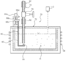
- FIG. 1 is an entire configuration diagram of a continuous coating apparatus according to an embodiment of the present invention.
- FIG. 2 is a detailed configuration diagram of a supply unit in the continuous coating apparatus according to the embodiment of the present invention.
- FIG. 3 is a configuration diagram of a levitation-heating unit in the continuous coating apparatus according to the embodiment of the present invention.
- FIG. 4 is a configuration diagram of electromagnetic coils in the levitation-heating unit of FIG. 3.
- FIG. 5 is a detailed configuration diagram of a vapor guide unit according to an embodiment of the present invention.
- FIG. 1 is an entire configuration diagram of a continuous coating apparatus according to an embodiment of the present invention.
- a coating target is a substrate 10 which continuously passes through a vacuum chamber unit, and a liquid coating material is a molten metal m.
- the substrate 10 may be a continuously moving metal strip.
- the continuous coating apparatus may also be configured so that the top and bottom surfaces of the substrate 10 are simultaneously coated in a single vacuum chamber by connecting an upper levitation-heating unit 50 and a supply pipe 74 communicating with a crucible 72 of a supply unit 70.
- two vacuum chamber units may be connected together and lines may be provided such that the bottom surface and the top surface of the substrate 10 (or the top surface and the bottom surface thereof) are sequentially coated.
- the continuous coating apparatus 1 may include a vacuum chamber unit 30 through which a coating target passes, a levitation-heating unit 50 disposed within the vacuum chamber unit 30 to vaporize a supplied coating material and generate an evaporation vapor, and a liquid coating material supply unit 70 connected so that a liquid coating material is supplied to at least one of an upper portion and a lower portion of the levitation-heating unit 50, and communicating with the outside of the vacuum chamber unit 30.
- the continuously moving substrate 10 passes through the vacuum chamber unit 30, and a molten metal m supplied from the molten metal supply unit 70 is continuously heated and levitated by the levitation-heating unit 50 and is generated as an evaporation (metal) vapor (G in FIGS. 1 and 3).
- the generated evaporation vapor may be a single component such as zinc (Zn) vapor, or an alloy component such as a zinc-magnesium (Zn-Mg) vapor.
- the evaporation vapor is continuously evaporated onto the moving substrate 10, thereby achieving a continuous coating.
- the inside of the vacuum chamber unit 30 is maintained in a vacuum environment by a vacuum pump (not shown), and guide rolls 32 are installed in the front and rear of the vacuum chamber unit 30.
- the guide rolls 32 support the continuous movement of the substrate 10 and seal an inlet and an outlet which are opened to allow the substrate 10 to pass through the vacuum chamber unit 30.
- the continuous coating apparatus 1 may further include a vapor guide unit 34 inside the vacuum chamber unit 30.
- the vapor guide unit 34 communicates with the liquid molten metal supply unit 70 and encloses at least a portion of the levitation-heating unit 50.
- the vapor guide unit 34 guides the evaporation vapor G to be sprayed toward the substrate 10.
- the vapor guide unit 34 serves as a guide pipe which prevents the dispersion of the evaporation vapor G, which is generated by levitating and heating the supplied molten metal m by the electromagnetic force of electromagnetic coils of the levitation-heating unit 50, which will be described later in detail, and is finally evaporated onto the substrate 10.
- the vapor guide unit 34 achieves the spraying of the evaporation vapor G toward the substrate 10 and the evaporation on the substrate 10 through a spray opening (a nozzle opening) 36 disposed at the upper portion thereof.
- the vapor guide unit 34 may have a T shape in correspondence with the width of the substrate 10, when viewed from the front, as illustrated in FIG. 5.
- the vapor guide unit 34 includes an evaporation vapor generation section 34a which is supplied with the molten metal m and encloses the levitation-heat unit 50.
- the molten metal supply pipe 74 provided in the molten metal supply unit 70 may be connected to either or both of a lower portion and an upper portion (not shown) of the evaporation vapor generation unit 34a.
- the liquid coating material i.e., the molten metal m, may be supplied through various supply paths.
- the vapor guide unit 34 may include a vapor guide section 34b connected to the upper portion of the evaporation vapor generation unit 34a, and an evaporation vapor nozzle section 34c connected to the upper portion of the evaporation vapor generation section 34a or the vapor guide section 34b.
- the evaporation vapor nozzle section 34c includes an evaporation vapor spray opening 36 elongated in correspondence with the width of the substrate 10.
- the evaporation vapor generation section 34a, the vapor guide section 34b, and the evaporation vapor nozzle section 34c may be integrally provided or may be assembled in a flange structure.
- the evaporation vapor generation section 34a and the vapor guide section 34b of the vapor guide unit 34 may be provided in a tube form.
- the spray opening 36 may be provided in a pipe structure or a casing structure having a rectangular cross-section which is substantially equal to that of the substrate 10 to be coated.
- the spray opening 36 formed in the evaporation vapor nozzle section 34c may be opened in an integrated slit shape, or, although not illustrated, a plurality of (circular or rectangular) holes may be formed in a predetermined pattern.
- the evaporation vapor generation section 34a which is the levitation-heating space in which the molten metal m being the supplied coating material is levitated and heated, may be made of an electrically nonconductive material, for example, a ceramic.
- the vapor guide section 34b and the vapor nozzle section 34c of the vapor guide unit 34 may be connected to a heating unit 90, e.g., a heater, in order that the evaporation vapor G passing through the inside thereof can be easily coated on the substrate 10.
- a heating unit 90 e.g., a heater
- the heating unit 90 is provided to enclose the outside of the guide section 34b as illustrated in FIG. 5, the heating unit 90 may also be provided at the inside thereof.
- the heating unit 90 i.e., the heater, which is connected to the evaporation vapor guide section 34b, may be spaced apart by at least once a distance equal to the inner diameter or at least twice a distance equal to the inner radius of the first electromagnetic coil 52 provided at the upper portion of the levitation-heating unit 50, in order to prevent the heating unit 92, i.e., the heater, from being overheated by the influence of the electromagnetic force upon the levitation-heating process.
- the molten metal supply unit 70 of the continuous coating apparatus 1 may include a crucible 72 and a molten metal supply pipe 74.
- the crucible 72 is disposed outside the vacuum chamber unit 30 and stores the coating material, i.e., the molten metal m.
- the molten metal supply pipe 74 is connected between the crucible 72 and the vapor guide unit 34 enclosing the levitation-heating unit 50 disposed inside the vacuum chamber unit 30.
- the solid metal is supplied to the crucible 72 and heated therein. Then, the liquid molten metal m is stored in the crucible 72. The liquid molten metal m is continuously supplied to the levitation-heating unit 50.
- the lower portion of the molten metal supply pipe 74 is dipped into the molten metal m stored in the crucible 72, and the upper portion of the molten metal supply pipe 74 is connected to the vapor guide unit 34 disposed inside the vacuum chamber unit 30. Consequently, since the vacuum chamber unit 30 is in a vacuum environment and the crucible 72 is in an atmospheric environment, a pressure difference of about 1 bar occurs between the vacuum and the atmosphere. Due to the pressure difference, the molten metal m is supplied to the evaporation vapor generation section 34a of the vapor guide unit 34.
- known heating units 92 and 94 such as a heater or a high-frequency induction heater, may be disposed to be adjacent to the molten metal supply pipe 74 and the crucible 72 of the molten metal supply unit 70.
- the heating unit 92 i.e., the heater, which is connected to the molten metal supply pipe 74 adjacent to the second electromagnetic coil 54 of the levitation-heating unit 50, may be spaced apart by at least once a distance equal to the inner diameter (d in FIG. 3) or at least twice a distance equal to the inner radius of the lowermost portion wound by the second electromagnetic coil 54 disposed at the lower portion of the levitation-heating unit 50, in order to prevent the heating unit 92, i.e., the heater, from being overheated by the influence of the electromagnetic force upon the levitation-heating process.
- the molten metal m is stored in the crucible 72 in a molten state.
- the crucible 72 and the supply pipe 74 can be maintained at an appropriate temperature while the molten metal m is being supplied to the evaporation vapor generation section 34a of the guide unit 34 through the supply pipe 74.
- a valve unit 76 may be installed in the supply pipe 74.
- the valve unit 76 may include an on/off valve which closes the supply pipe 74 when the vacuum environment is formed in the vacuum chamber, or a flow rate control valve which is opened or closed to control a supply amount of the molten metal m.
- the valves are not indicated by separate reference symbols.
- the amount of the molten metal supplied due to the pressure difference between the vacuum and the atmosphere may be adjusted by the on/off valve or the flow rate control valve, and the on/off valve closes the pipe when the initial vacuum environment is formed in the vacuum chamber.
- a dipping-type (flow rate control) valve unit 80 may be provided in the crucible 72 of the molten metal supply unit 70 according to the embodiment of the present invention.
- the dipping-type valve unit 80 may include an elevating arm 82 and an opening/closing member 84.
- the elevating arm 82 moves up and down by a driving cylinder 86 or an electric actuator provided at a bracket on the crucible 72, and is dipped into the molten metal m.
- the opening/closing member 84 moves toward the molten metal inlet of the supply pipe 74 at the lower portion of the elevating arm 82.
- the elevating arm 82 moves up and down according to the operation of the driving cylinder.
- a screw bar 88b is connected to and driven by a driving motor 88a installed at the bracket on the crucible 72.
- the elevating arm 82 may be connected to a moving block 88c of the dipping-type valve unit 80.
- An adjacent guide rod 88d passes through the moving block 88c and is supported thereby.
- the moving block 88c connected to the screw bar 88b is supported by the guide rod and is elevated according to the operation of the driving motor 88a.
- the elevating arm 82 and the opening/closing member 84 disposed thereunder opens/closes the inlet of the supply pipe 74 while integrally moving up and down according to the elevation of the moving block 88c. Therefore, even in the case of FIG. 2, the supply amount of the molten metal m can be smoothly adjusted.
- the elevating structure in which the motor-driven screw bar 88b is connected to the moving block 88c in which the elevating arm 82 is connected to the screw bar 88b is complicated, as compared to the structure of FIG. 1 in which the cylinder 86 (or the actuator) is used.
- the opening/closing of the supply pipe 74 can be more precisely controlled through the elevating range control of the elevating arm 82.
- the continuous coating apparatus reduces heating load because it supplies the liquid material, i.e., the molten metal, instead of the solid material, i.e., the wire, upon the levitation-heating process.
- the evaporation vapor can be generated more smoothly and the costs can be further reduced.
- the structure of the molten metal supply unit 70 uses the dipping-type valve units which use the pressure difference and can control the supply flow rate. Therefore, the entire structure of the continuous coating apparatus can be simplified, and the substrate coating workability or precision can be at least maintained or improved.
- the levitation-heating unit 50 which can generate the evaporation vapor G by levitating and heating the molten metal m may include the first and second electromagnetic coils 52 and 54 enclosing the evaporation vapor generation section 34a of the vapor guide unit 34 disposed inside the vacuum chamber unit 30.
- the first and second electromagnetic coils 52 and 54 of the levitation-heating unit 50 generate a strong induced eddy current in the supplied molten metal m by the interaction of a magnetic field between the electromagnetic coils, generated by a high frequency power applied through an AC power supply 56 connected thereto, and an induced current generated therein.
- the supplied molten metal m is heated at a sufficient high temperature in a levitated state and is then vaporized and generated as the evaporation vapor G.
- a high-frequency alternating current of about 1-1,000 kHz may be applied to the first and second electromagnetic coils 52 and 54 through the AC power supply 56, and the electromagnetic force is generated in the electromagnetic coils by the applied high-frequency alternating current.
- the molten metal m supplied therein is levitated by the Lorentz force, heated at a high temperature by an induction heating principle, and generated as the evaporation vapor.
- the first and second electromagnetic coils 52 and 54 of the levitation-heating unit 50 may be spaced apart by a predetermined interval S.
- the first electromagnetic coil 52 may be formed in a cylindrical shape in order to smoothly discharge the evaporation vapor (metal vapor) (G in FIG. 3).
- the second electromagnetic coil 54 may be formed in a conical shape, which is gradually narrowed downwardly, in order to increase the levitation force of the molten metal and stably maintain the levitation heating.
- the second electromagnetic coil 54 may be formed in a 'Y' shape or a 'V' shape.
- the levitation force is increased at the second electromagnetic coil 54.
- both of the first and second electromagnetic coils 52 and 54 may be formed to have a cylindrical shape.
- the molten metal supply pipe 74 supplies the molten metal m in such a state that it is connected to either or both of the upper portion and the lower portion of the evaporation vapor generation section 34a of the vapor guide unit 34 enclosing the first and second electromagnetic coils 52 and 54 of the levitation-heating unit 50, more various molten metal supply paths are provided, as opposed to the conventional art in which the supply of the solid wire is limited to the lateral direction (the horizontal direction). Hence, the setting of the apparatus, the space utilization, or the coating workability can be improved.
- At least two upper and lower supply paths can be implemented which connect the molten metal supply pipe 74 to the lower portion of the evaporation vapor generation section 34a of the vapor guide unit 34 through the lower center of the second electromagnetic coil 54, or connect the upper portion of the first electromagnetic coil 52 to the upper portion of the evaporation vapor generation section 34a.
- the first electromagnetic coil 52 disposed at the upper portion of the levitation-heating unit 50 and the second electromagnetic coil 54 disposed at the lower portion of the levitation-heating unit 50 may be wound in an opposite direction to each other. Since the current flows in the opposite direction, an offset of magnetic field is generated within the coils and the molten metal is more stably levitated.
- the gap (g in FIG. 3) between the first electromagnetic coil 52 and the second electromagnetic coil 54 be narrow to some extent in terms of the increase in the heat generation. However, if the gap between the first electromagnetic coil 52 and the second electromagnetic coil 54 is excessively narrow, excessive heat is generated. Thus, it is suitable that the first electromagnetic coil 52 and the second electromagnetic coil 54 be spaced apart from each other by an appropriate interval.
- the first and second electromagnetic coils 52 and 54 may be wound to have the same center line.
- the levitation position of the supplied molten metal m may be adjusted to the center of the first and second electromagnetic coils 52 and 54.
- both of the first and second electromagnetic coils 52 and 54 may be wound in a cylindrical shape.
- a filter member 130 may be provided in the vicinity of the evaporation vapor spray opening 36 provided at the evaporation vapor nozzle section 34c of the vapor guide unit 34.
- the filter member 130 may be provided in the vicinity of the evaporation vapor nozzle section 34c, for example, at the inside or outside of the spray opening or on the opening line in which the spray opening is formed.
- the filter member 130 serves to remove an aggregation which may be contained in the generated evaporation vapor.
- the filter member 130 may be disposed in the vicinity of at least the spray opening 36, and it may be disposed on the moving path of the evaporation vapor before the evaporation vapor is evaporated onto the substrate.
- the filter member 130 may be provided in a fabric structure (a mesh structure) using a heat-resistant metal or a ceramic material.
- the filter member 130 may be provided by weaving wires made of a metal or ceramic material resistant to high temperature.
- vapor aggregation is removed when the evaporation vapor passes through the filter member 130.
- Vapor aggregation which does not pass through the filter member 130 is molten at high temperature and is again vaporized.
- the filter member 130 makes it possible to uniformly coat film on the substrate.
- a level detection sensor 110 detecting the level of the coating material stored in the crucible 72, that is, the molten metal, may be disposed.
- the level detection sensor 110, the valve unit 76 and the driving cylinder 86 (or the electric driving actuator) of the dipping-type valve unit 80, or the screw bar driving motor 88a of FIG. 2, and the AC power supply 56 of the levitation-heating unit 50 may be controlled in electrical connection to an apparatus control unit C and controlled.
- the apparatus control unit C may control the valves and precisely control the supply amount of the molten metal in interconnection to the level detection sensor, and can control the alternating current applied to the first and second electromagnetic coils 52 and 54 of the levitation-heating unit 50.
- the apparatus control unit C can control the heating temperature in electrical connection to the heating units 90, 92 and 94.
- the apparatus control unit C receives a signal from a sensor (not shown) detecting a transfer speed of a substrate to be coated, and controls an amount of the evaporation vapor to be coated on the substrate through the above-described interconnection configuration, thereby achieving the optimum continuous coating and the high-speed coating.
- the present invention provides the continuous coating apparatus which can perform a high-speed coating on a substrate metal strip which is the moving coating target(the metal strip), and in particular, can supply a liquid coating material(a molten metal) to a levitation-heating space through various paths.
- the present invention also provides the continuous coating apparatus which can easily control a supply flow rate of the liquid coating material, and can improve coating workability and precision, and has a simplified structure.
Abstract
Description
Claims (11)
- A continuous coating apparatus comprising:a vacuum chamber unit through which a coating target passes;a levitation-heating unit disposed in the vacuum chamber unit and generating an evaporation vapor by vaporizing a supplied coating material; anda liquid coating material supply unit connected so that a liquid coating material is supplied to at least one of an upper portion and a lower portion of the levitation-heating unit, and communicating with the outside of the vacuum chamber unit.
- The continuous coating apparatus of claim 1, wherein the levitation-heating unit comprises one or more electromagnetic coils which levitate and heat the supplied coating material by an electromagnetic force and generate the evaporation vapor.
- The continuous coating apparatus of claim 1, wherein the liquid coating material supply unit comprises:a crucible disposed outside the vacuum chamber and storing the liquid coating material; anda coating material supply pipe connected between the crucible and the levitation-heating unit disposed inside the vacuum chamber unit.
- The continuous coating apparatus of claim 1, further comprising a vapor guide unit connected to the liquid coating material supply unit inside the vacuum chamber unit and enclosing at least a portion of the levitation-heating unit, so that the evaporation vapor generated from the inside thereof is guided and sprayed to the coating target.
- The continuous coating apparatus of claim 4, wherein the vapor guide unit comprises:an evaporation vapor generation section the liquid coating material supplied therein and enclosing the levitation-heating unit, the coating material supply pipe provided in the liquid coating material supply unit being connected to one of an upper portion and a lower portion of the evaporation vapor generation section; and,at least an evaporation vapor nozzle section of a vapor guide section connected to the evaporation vapor generation section, and the evaporation vapor nozzle section connected to the evaporation vapor generation section or the vapor guide section;wherein the evaporation vapor nozzle section including an evaporation vapor spray opening formed in correspondence with the width of the coating target.
- The continuous coating apparatus of claim 5, wherein,the evaporation vapor generation section and the vapor guide section of the vapor guide unit are provided in a tube form,the evaporation vapor generation unit is made of an electrically nonconductive material, andat least one of the vapor guide section and the evaporation vapor nozzle section of the vapor guide unit is connected to a heating unit.
- The continuous coating apparatus of claim 5, further comprising a filter member disposed in the vicinity of the evaporation vapor spray opening provided in the evaporation vapor nozzle section so that the evaporation vapor passes therethrough, the filter member being made in a fabric structure by using a heat-resistant metal or ceramic material.
- The continuous coating apparatus of claim 3, further comprising at least one of:a valve unit provided in the coating material supply pipe; anda dipping-type valve unit including an opening/closing member provided at a lower portion of an elevating member, a portion of which is dipped into the coating material stored in the crucible, so that the dipping-type valve unit controls an opening/closing degree of the coating material supply pipe,whereby the supply flow rate of the coating material is controlled.
- The continuous coating apparatus of claim 3, further comprising heating units which are respectively connected to the crucible and the supply pipe provided in the liquid coating material supply unit.
- The continuous coating apparatus of any one of claims 1 to 9, wherein the coating target is provided in a form of a substrate continuously passing through the vacuum chamber, and the liquid coating material is provided in a form of a molten metal.
- The continuous coating apparatus of claim 6 or 9, wherein the heating unit disposed at the vapor guide unit or the heating unit disposed at the supply pipe are spaced apart by a distance equal to at least once the inner diameter or a distance equal to at least twice the inner radius of the electromagnetic coil disposed to be adjacent thereto and wound.
Priority Applications (5)
| Application Number | Priority Date | Filing Date | Title |
|---|---|---|---|
| JP2013544368A JP5797275B2 (en) | 2010-12-13 | 2010-12-13 | Continuous coating equipment |
| PCT/KR2010/008889 WO2012081738A1 (en) | 2010-12-13 | 2010-12-13 | Continuous coating apparatus |
| CN201080070535.6A CN103249860B (en) | 2010-12-13 | 2010-12-13 | Continuous coating apparatus |
| EP10860794.6A EP2652167B1 (en) | 2010-12-13 | 2010-12-13 | Continuous coating apparatus |
| US13/824,494 US9267203B2 (en) | 2010-12-13 | 2010-12-13 | Continuous coating apparatus |
Applications Claiming Priority (1)
| Application Number | Priority Date | Filing Date | Title |
|---|---|---|---|
| PCT/KR2010/008889 WO2012081738A1 (en) | 2010-12-13 | 2010-12-13 | Continuous coating apparatus |
Publications (1)
| Publication Number | Publication Date |
|---|---|
| WO2012081738A1 true WO2012081738A1 (en) | 2012-06-21 |
Family
ID=46244827
Family Applications (1)
| Application Number | Title | Priority Date | Filing Date |
|---|---|---|---|
| PCT/KR2010/008889 WO2012081738A1 (en) | 2010-12-13 | 2010-12-13 | Continuous coating apparatus |
Country Status (5)
| Country | Link |
|---|---|
| US (1) | US9267203B2 (en) |
| EP (1) | EP2652167B1 (en) |
| JP (1) | JP5797275B2 (en) |
| CN (1) | CN103249860B (en) |
| WO (1) | WO2012081738A1 (en) |
Cited By (5)
| Publication number | Priority date | Publication date | Assignee | Title |
|---|---|---|---|---|
| EP2746423A1 (en) * | 2012-12-20 | 2014-06-25 | Applied Materials, Inc. | Evaporator, deposition arrangement, deposition apparatus and methods of operation thereof |
| WO2017191081A1 (en) | 2016-05-03 | 2017-11-09 | Tata Steel Nederland Technology B.V. | Method to control the temperature of an electromagnetic pump |
| WO2017191082A1 (en) | 2016-05-03 | 2017-11-09 | Tata Steel Nederland Technology B.V. | Apparatus for feeding a liquid material to an evaporator device |
| WO2017191083A1 (en) | 2016-05-03 | 2017-11-09 | Tata Steel Nederland Technology B.V. | Method to operate an apparatus for feeding liquid metal to an evaporator device |
| EP3561146A4 (en) * | 2016-12-26 | 2019-11-06 | Posco | Single layer zinc alloy plated steel material exhibiting excellent spot weldability and corrosion resistance, and fabrication method therefor |
Families Citing this family (19)
| Publication number | Priority date | Publication date | Assignee | Title |
|---|---|---|---|---|
| MX2014013233A (en) * | 2014-10-30 | 2016-05-02 | Ct Investig Materiales Avanzados Sc | Injection nozzle for aerosols and their method of use to deposit different coatings via vapor chemical deposition assisted by aerosol. |
| EP3124648B1 (en) * | 2015-07-31 | 2018-03-28 | Hilberg & Partner GmbH | Evaporator system and evaporation method for coating a strip-shaped substrate |
| DE102015214666A1 (en) * | 2015-07-31 | 2017-02-02 | TRUMPF Hüttinger GmbH + Co. KG | Inductor and inductor arrangement |
| KR101940886B1 (en) * | 2016-12-26 | 2019-01-21 | 주식회사 포스코 | Zinc alloy plated steel material having excellent spot weldability and corrosion resistance |
| EP3587613A4 (en) * | 2017-02-24 | 2020-01-01 | JFE Steel Corporation | Continuous molten metal plating apparatus and molten metal plating method using said apparatus |
| US20190048460A1 (en) * | 2017-08-14 | 2019-02-14 | Wuhan China Star Optoelectronics Semiconductor Display Technology Co., Ltd. | Evaporation Crucible and Evaporation System |
| KR102109242B1 (en) * | 2017-12-26 | 2020-05-11 | 주식회사 포스코 | Multi-layered zinc alloy plated steel material having excellent spot weldability and corrosion resistance |
| IT201800006804A1 (en) * | 2018-06-29 | 2019-12-29 | METAL LEVEL DETECTION DEVICE IN AN ELECTRIC ARC OVEN | |
| KR20200076389A (en) * | 2018-12-19 | 2020-06-29 | 주식회사 포스코 | Apparatus and method for controlling coating layer in pvd plating processs |
| CN112553577A (en) | 2019-09-26 | 2021-03-26 | 宝山钢铁股份有限公司 | Vacuum coating device for improving vacuum coating yield |
| CN112553578B (en) | 2019-09-26 | 2022-01-14 | 宝山钢铁股份有限公司 | Vacuum coating device with flow-inhibiting nozzle |
| CN112575308B (en) | 2019-09-29 | 2023-03-24 | 宝山钢铁股份有限公司 | Vacuum coating device capable of efficiently coating strip steel under vacuum |
| KR102319130B1 (en) * | 2020-03-11 | 2021-10-29 | 티오에스주식회사 | Metal-Oxide semiconductor evaporation source equipped with variable temperature control module |
| CN113564534B (en) * | 2020-04-28 | 2023-05-09 | 宝山钢铁股份有限公司 | Continuous plating solution supply device and method for vacuum plating unit |
| CN113957390B (en) * | 2020-07-21 | 2024-03-08 | 宝山钢铁股份有限公司 | Vacuum coating device with air cushion buffer cavity |
| CN113957392B (en) | 2020-07-21 | 2022-09-20 | 宝山钢铁股份有限公司 | Vacuum coating device adopting uniform mixing buffer structure to uniformly distribute metal steam |
| CN113957389B (en) * | 2020-07-21 | 2023-08-11 | 宝山钢铁股份有限公司 | Vacuum coating device with porous noise reduction and uniform distribution of metal vapor |
| CN113957388B (en) | 2020-07-21 | 2022-08-16 | 宝山钢铁股份有限公司 | Vacuum coating device adopting guide plate type structure to uniformly distribute metal steam |
| CN113957391B (en) * | 2020-07-21 | 2023-09-12 | 宝山钢铁股份有限公司 | Vacuum coating device adopting core rod heating structure to uniformly distribute metal vapor |
Citations (5)
| Publication number | Priority date | Publication date | Assignee | Title |
|---|---|---|---|---|
| US5239611A (en) * | 1991-02-14 | 1993-08-24 | Hilmar Weinert | Series evaporator |
| JPH11128719A (en) * | 1997-10-31 | 1999-05-18 | Fujitsu Ltd | Apparatus for vaporizing solution and apparatus for producing membrane |
| JP2006111926A (en) * | 2004-10-15 | 2006-04-27 | Hitachi Zosen Corp | Vapor deposition system |
| JP2009084665A (en) * | 2007-09-10 | 2009-04-23 | Ulvac Japan Ltd | Supply device and vapor deposition apparatus |
| KR100926437B1 (en) * | 2008-11-17 | 2009-11-13 | 에스엔유 프리시젼 주식회사 | Deposition material supply apparatus and Equipment for treating substrate having the same |
Family Cites Families (43)
| Publication number | Priority date | Publication date | Assignee | Title |
|---|---|---|---|---|
| US2664852A (en) * | 1950-04-27 | 1954-01-05 | Nat Res Corp | Vapor coating apparatus |
| US3059612A (en) * | 1959-10-19 | 1962-10-23 | Wean Engineering Co Inc | Vacuum coating apparatus |
| US3227132A (en) * | 1962-12-31 | 1966-01-04 | Nat Res Corp | Apparatus for depositing coatings of tin on a flexible substrate |
| US3408224A (en) * | 1964-06-25 | 1968-10-29 | Pennsalt Chemicals Corp | Vapor coating employing degassing of coating metal |
| US3371186A (en) * | 1967-05-01 | 1968-02-27 | William J. Trabilcy | Type metal transportation systems |
| US3815623A (en) * | 1971-11-04 | 1974-06-11 | Farmer Mold & Machine Works | Molten metal delivery system |
| US4356940A (en) * | 1980-08-18 | 1982-11-02 | Lester Engineering Company | Apparatus for dispensing measured amounts of molten metal |
| JPS59113179A (en) * | 1982-12-20 | 1984-06-29 | Mitsubishi Heavy Ind Ltd | Vacuum deposition device and start-up method thereof |
| JPS59177370A (en) | 1983-03-29 | 1984-10-08 | Mitsubishi Heavy Ind Ltd | Vacuum deposition device |
| JPS62248557A (en) * | 1986-04-18 | 1987-10-29 | Yuasa Battery Co Ltd | Method and aparatus for supplying lead alloy to casting machine |
| JPS63119966A (en) * | 1986-11-10 | 1988-05-24 | Toshiba Mach Co Ltd | Method for quick discharge of molten metal in molten metal supply system in pressurization type molten metal holding furnace |
| US5002837A (en) * | 1988-07-06 | 1991-03-26 | Kabushiki Kaisha Kobe Seiko Sho | Zn-Mg alloy vapor deposition plated metals of high corrosion resistance, as well as method of producing them |
| US5250103A (en) * | 1991-03-04 | 1993-10-05 | Ryobi Ltd. | Automatic molten metal supplying device and method for supplying the molten metal |
| JP3563083B2 (en) | 1992-09-11 | 2004-09-08 | 真空冶金株式会社 | Method and apparatus for gas deposition of ultrafine particles |
| NO175571C (en) * | 1992-10-23 | 1994-11-02 | Norsk Hydro As | Dosing pump for metal |
| US5454423A (en) * | 1993-06-30 | 1995-10-03 | Kubota Corporation | Melt pumping apparatus and casting apparatus |
| JP3097400B2 (en) * | 1993-07-20 | 2000-10-10 | トヨタ自動車株式会社 | Vacuum casting and its equipment |
| US5556592A (en) * | 1994-08-15 | 1996-09-17 | Hitchings; Jay | Filter indexing apparatus for filtering molten metal |
| US5630464A (en) * | 1995-11-03 | 1997-05-20 | Spartan Light Metal Products, Inc. | Cold chamber magnesium pump assembly |
| JPH108240A (en) * | 1996-06-25 | 1998-01-13 | Mitsubishi Heavy Ind Ltd | Vacuum vapor deposition device |
| JP3068600B1 (en) * | 1999-03-19 | 2000-07-24 | 幸久 長子 | Automatic hot water injection system |
| US6578620B1 (en) * | 1999-07-02 | 2003-06-17 | Alcoa Inc. | Filtering molten metal injector system and method |
| US20020084054A1 (en) * | 1999-08-02 | 2002-07-04 | Trudel David R. | Ball check valve molten metal injector |
| EP1174526A1 (en) * | 2000-07-17 | 2002-01-23 | Nederlandse Organisatie voor Toegepast Natuurwetenschappelijk Onderzoek TNO | Continuous vapour deposition |
| EP1182272A1 (en) * | 2000-08-23 | 2002-02-27 | Cold Plasma Applications C.P.A. | Process and apparatus for continuous cold plasma deposition of metallic layers |
| US20040191097A1 (en) * | 2001-06-06 | 2004-09-30 | Kenichi Nakagawa | Molten metal feeder |
| NL1020059C2 (en) * | 2002-02-21 | 2003-08-25 | Corus Technology B V | Method and device for coating a substrate. |
| TWI277363B (en) | 2002-08-30 | 2007-03-21 | Semiconductor Energy Lab | Fabrication system, light-emitting device and fabricating method of organic compound-containing layer |
| DE10316758A1 (en) * | 2003-04-10 | 2004-10-28 | Bühler AG | Holding furnace and dosing device for molten metal |
| DE50305957D1 (en) * | 2003-06-13 | 2007-01-25 | Meltec Industrieofenbau Gmbh | Apparatus for charging casting equipment with molten metal |
| US20050229856A1 (en) * | 2004-04-20 | 2005-10-20 | Malik Roger J | Means and method for a liquid metal evaporation source with integral level sensor and external reservoir |
| LV13383B (en) * | 2004-05-27 | 2006-02-20 | Sidrabe As | Method and device for vacuum vaporization metals or alloys |
| KR100784253B1 (en) * | 2004-07-22 | 2007-12-11 | 가부시키가이샤 호에이 쇼카이 | System for supplying molten metal, container and a vehicle |
| ATE428290T1 (en) * | 2004-08-23 | 2009-04-15 | Corus Technology Bv | APPARATUS AND METHOD FOR FLOATING A QUANTITY OF CONDUCTIVE MATERIAL |
| ZA200701534B (en) * | 2004-08-23 | 2008-10-29 | Corus Technology Bv | Apparatus and method for levitation of an amount of conductive material |
| TWI276689B (en) * | 2005-02-18 | 2007-03-21 | Nippon Steel Corp | Induction heating device for a metal plate |
| WO2006128532A1 (en) * | 2005-05-31 | 2006-12-07 | Corus Technology Bv | Apparatus and method for coating a substrate |
| JP2007227086A (en) * | 2006-02-22 | 2007-09-06 | Tokyo Electron Ltd | Deposition apparatus and method of manufacturing light emitting element |
| US20080190970A1 (en) * | 2007-02-13 | 2008-08-14 | Pyrotek, Inc. | Dosing system |
| EP1972699A1 (en) | 2007-03-20 | 2008-09-24 | ArcelorMittal France | Method of coating a substrate under vacuum |
| WO2009034915A1 (en) | 2007-09-10 | 2009-03-19 | Ulvac, Inc. | Evaporation apparatus |
| EP2048261A1 (en) * | 2007-10-12 | 2009-04-15 | ArcelorMittal France | Industrial steam generator for depositing an alloy coating on a metal band |
| KR101207719B1 (en) * | 2010-12-27 | 2012-12-03 | 주식회사 포스코 | Dry Coating Apparatus |
-
2010
- 2010-12-13 WO PCT/KR2010/008889 patent/WO2012081738A1/en active Application Filing
- 2010-12-13 JP JP2013544368A patent/JP5797275B2/en active Active
- 2010-12-13 EP EP10860794.6A patent/EP2652167B1/en active Active
- 2010-12-13 CN CN201080070535.6A patent/CN103249860B/en active Active
- 2010-12-13 US US13/824,494 patent/US9267203B2/en active Active
Patent Citations (5)
| Publication number | Priority date | Publication date | Assignee | Title |
|---|---|---|---|---|
| US5239611A (en) * | 1991-02-14 | 1993-08-24 | Hilmar Weinert | Series evaporator |
| JPH11128719A (en) * | 1997-10-31 | 1999-05-18 | Fujitsu Ltd | Apparatus for vaporizing solution and apparatus for producing membrane |
| JP2006111926A (en) * | 2004-10-15 | 2006-04-27 | Hitachi Zosen Corp | Vapor deposition system |
| JP2009084665A (en) * | 2007-09-10 | 2009-04-23 | Ulvac Japan Ltd | Supply device and vapor deposition apparatus |
| KR100926437B1 (en) * | 2008-11-17 | 2009-11-13 | 에스엔유 프리시젼 주식회사 | Deposition material supply apparatus and Equipment for treating substrate having the same |
Non-Patent Citations (1)
| Title |
|---|
| See also references of EP2652167A4 * |
Cited By (15)
| Publication number | Priority date | Publication date | Assignee | Title |
|---|---|---|---|---|
| CN111304595A (en) * | 2012-12-20 | 2020-06-19 | 应用材料公司 | Evaporator, deposition apparatus and method of operating the same |
| CN104884664A (en) * | 2012-12-20 | 2015-09-02 | 应用材料公司 | Evaporator, deposition arrangement, deposition apparatus and methods of operation thereof |
| JP2016507644A (en) * | 2012-12-20 | 2016-03-10 | アプライド マテリアルズ インコーポレイテッドApplied Materials,Incorporated | Evaporator, deposition arrangement, deposition apparatus and method for operating them |
| WO2014096302A1 (en) * | 2012-12-20 | 2014-06-26 | Applied Materials, Inc. | Evaporator, deposition arrangement, deposition apparatus and methods of operation thereof |
| JP2019007082A (en) * | 2012-12-20 | 2019-01-17 | アプライド マテリアルズ インコーポレイテッドApplied Materials,Incorporated | Evaporator, deposition arrangement, deposition apparatus, and methods of operation thereof |
| EP2746423A1 (en) * | 2012-12-20 | 2014-06-25 | Applied Materials, Inc. | Evaporator, deposition arrangement, deposition apparatus and methods of operation thereof |
| US11713506B2 (en) | 2012-12-20 | 2023-08-01 | Applied Materials, Inc. | Evaporator, deposition arrangement, deposition apparatus and methods of operation thereof |
| US11414744B2 (en) | 2016-05-03 | 2022-08-16 | Tata Steel Nederland Technology B.V. | Method to operate an apparatus for feeding liquid metal to an evaporator device |
| WO2017191081A1 (en) | 2016-05-03 | 2017-11-09 | Tata Steel Nederland Technology B.V. | Method to control the temperature of an electromagnetic pump |
| WO2017191082A1 (en) | 2016-05-03 | 2017-11-09 | Tata Steel Nederland Technology B.V. | Apparatus for feeding a liquid material to an evaporator device |
| WO2017191083A1 (en) | 2016-05-03 | 2017-11-09 | Tata Steel Nederland Technology B.V. | Method to operate an apparatus for feeding liquid metal to an evaporator device |
| US11220739B2 (en) | 2016-05-03 | 2022-01-11 | Tata Steel Nederland Technology B.V. | Apparatus for feeding a liquid material to an evaporator device |
| US11261860B2 (en) | 2016-05-03 | 2022-03-01 | Tata Steel Nederland Technology B.V. | Method to control the temperature of an electromagnetic pump |
| EP3561146A4 (en) * | 2016-12-26 | 2019-11-06 | Posco | Single layer zinc alloy plated steel material exhibiting excellent spot weldability and corrosion resistance, and fabrication method therefor |
| US11203802B2 (en) | 2016-12-26 | 2021-12-21 | Posco | Single layer zinc alloy plated steel material exhibiting excellent spot weldability and corrosion resistance, and fabrication method therefor |
Also Published As
| Publication number | Publication date |
|---|---|
| US20130199447A1 (en) | 2013-08-08 |
| CN103249860B (en) | 2016-03-16 |
| JP5797275B2 (en) | 2015-10-21 |
| EP2652167A4 (en) | 2014-04-30 |
| US9267203B2 (en) | 2016-02-23 |
| EP2652167A1 (en) | 2013-10-23 |
| EP2652167B1 (en) | 2015-04-08 |
| JP2013545900A (en) | 2013-12-26 |
| CN103249860A (en) | 2013-08-14 |
Similar Documents
| Publication | Publication Date | Title |
|---|---|---|
| WO2012081738A1 (en) | Continuous coating apparatus | |
| KR101639813B1 (en) | Continuous Coating Apparatus | |
| KR101530183B1 (en) | Industrial vapour generator for the deposition of an alloy coating onto a metal strip | |
| KR100607403B1 (en) | Vaporization equipment for vacuum deposition plant | |
| EP2168644B1 (en) | Evaporator for organic materials and method for evaporating organic materials | |
| US10196736B2 (en) | Heating apparatus, and coating device comprising same | |
| JP5064222B2 (en) | Apparatus and method for levitating a quantity of conductive material | |
| US9732423B2 (en) | Dry coating apparatus | |
| WO2016006741A1 (en) | Thin film deposition device having plurality of evaporation sources | |
| WO2012091391A2 (en) | Apparatus for removing pollutant source from snout of galvanizing line | |
| KR20110034420A (en) | Molten metal supplying apparatus | |
| CN105829573B (en) | Heating device and coating machine including the device | |
| WO2017111384A1 (en) | Vacuum deposition device for high-speed coating | |
| WO2016006740A1 (en) | Thin film deposition apparatus having plurality of crucibles | |
| WO2023128130A1 (en) | Plasma suspension coating system and method | |
| CN206109530U (en) | A gas injection ware unit for inciting somebody to action during process gas supplies evaporimeter source | |
| RU2391443C2 (en) | Vacuum coating aggregate | |
| WO2019132206A1 (en) | Deposition apparatus and deposition method | |
| EP3587618A2 (en) | Selective vapor deposition process for additive manufacturing | |
| WO2017086588A1 (en) | Deposition apparatus and deposition system using induction heating | |
| JP2554488B2 (en) | Magnetic recording medium manufacturing equipment | |
| JPH04120269A (en) | Method and device for vapor-depositing metal | |
| KR20180073961A (en) | Material Supplying Device and Vacuum Evaporation Coating Apparatus Having The Device |
Legal Events
| Date | Code | Title | Description |
|---|---|---|---|
| WWE | Wipo information: entry into national phase |
Ref document number: 201080070535.6 Country of ref document: CN |
|
| 121 | Ep: the epo has been informed by wipo that ep was designated in this application |
Ref document number: 10860794 Country of ref document: EP Kind code of ref document: A1 |
|
| WWE | Wipo information: entry into national phase |
Ref document number: 13824494 Country of ref document: US |
|
| ENP | Entry into the national phase |
Ref document number: 2013544368 Country of ref document: JP Kind code of ref document: A |
|
| NENP | Non-entry into the national phase |
Ref country code: DE |