WO2012156140A1 - Device for providing vacuum for the vacuum treatment of wounds - Google Patents
Device for providing vacuum for the vacuum treatment of wounds Download PDFInfo
- Publication number
- WO2012156140A1 WO2012156140A1 PCT/EP2012/055438 EP2012055438W WO2012156140A1 WO 2012156140 A1 WO2012156140 A1 WO 2012156140A1 EP 2012055438 W EP2012055438 W EP 2012055438W WO 2012156140 A1 WO2012156140 A1 WO 2012156140A1
- Authority
- WO
- WIPO (PCT)
- Prior art keywords
- container
- pressure
- suction pump
- vacuum
- housing part
- Prior art date
Links
- GDOPTJXRTPNYNR-UHFFFAOYSA-N CC1CCCC1 Chemical compound CC1CCCC1 GDOPTJXRTPNYNR-UHFFFAOYSA-N 0.000 description 1
- 0 CCI(C)C1*CCC1 Chemical compound CCI(C)C1*CCC1 0.000 description 1
Images


Classifications
-
- A—HUMAN NECESSITIES
- A61—MEDICAL OR VETERINARY SCIENCE; HYGIENE
- A61M—DEVICES FOR INTRODUCING MEDIA INTO, OR ONTO, THE BODY; DEVICES FOR TRANSDUCING BODY MEDIA OR FOR TAKING MEDIA FROM THE BODY; DEVICES FOR PRODUCING OR ENDING SLEEP OR STUPOR
- A61M1/00—Suction or pumping devices for medical purposes; Devices for carrying-off, for treatment of, or for carrying-over, body-liquids; Drainage systems
- A61M1/90—Negative pressure wound therapy devices, i.e. devices for applying suction to a wound to promote healing, e.g. including a vacuum dressing
- A61M1/96—Suction control thereof
- A61M1/964—Suction control thereof having venting means on or near the dressing
-
- A—HUMAN NECESSITIES
- A61—MEDICAL OR VETERINARY SCIENCE; HYGIENE
- A61M—DEVICES FOR INTRODUCING MEDIA INTO, OR ONTO, THE BODY; DEVICES FOR TRANSDUCING BODY MEDIA OR FOR TAKING MEDIA FROM THE BODY; DEVICES FOR PRODUCING OR ENDING SLEEP OR STUPOR
- A61M1/00—Suction or pumping devices for medical purposes; Devices for carrying-off, for treatment of, or for carrying-over, body-liquids; Drainage systems
- A61M1/71—Suction drainage systems
- A61M1/74—Suction control
-
- A—HUMAN NECESSITIES
- A61—MEDICAL OR VETERINARY SCIENCE; HYGIENE
- A61M—DEVICES FOR INTRODUCING MEDIA INTO, OR ONTO, THE BODY; DEVICES FOR TRANSDUCING BODY MEDIA OR FOR TAKING MEDIA FROM THE BODY; DEVICES FOR PRODUCING OR ENDING SLEEP OR STUPOR
- A61M1/00—Suction or pumping devices for medical purposes; Devices for carrying-off, for treatment of, or for carrying-over, body-liquids; Drainage systems
- A61M1/90—Negative pressure wound therapy devices, i.e. devices for applying suction to a wound to promote healing, e.g. including a vacuum dressing
- A61M1/98—Containers specifically adapted for negative pressure wound therapy
- A61M1/984—Containers specifically adapted for negative pressure wound therapy portable on the body
-
- A—HUMAN NECESSITIES
- A61—MEDICAL OR VETERINARY SCIENCE; HYGIENE
- A61M—DEVICES FOR INTRODUCING MEDIA INTO, OR ONTO, THE BODY; DEVICES FOR TRANSDUCING BODY MEDIA OR FOR TAKING MEDIA FROM THE BODY; DEVICES FOR PRODUCING OR ENDING SLEEP OR STUPOR
- A61M1/00—Suction or pumping devices for medical purposes; Devices for carrying-off, for treatment of, or for carrying-over, body-liquids; Drainage systems
- A61M1/84—Drainage tubes; Aspiration tips
- A61M1/85—Drainage tubes; Aspiration tips with gas or fluid supply means, e.g. for supplying rinsing fluids or anticoagulants
-
- A—HUMAN NECESSITIES
- A61—MEDICAL OR VETERINARY SCIENCE; HYGIENE
- A61M—DEVICES FOR INTRODUCING MEDIA INTO, OR ONTO, THE BODY; DEVICES FOR TRANSDUCING BODY MEDIA OR FOR TAKING MEDIA FROM THE BODY; DEVICES FOR PRODUCING OR ENDING SLEEP OR STUPOR
- A61M2205/00—General characteristics of the apparatus
- A61M2205/33—Controlling, regulating or measuring
- A61M2205/3331—Pressure; Flow
- A61M2205/3351—Controlling upstream pump pressure
-
- A—HUMAN NECESSITIES
- A61—MEDICAL OR VETERINARY SCIENCE; HYGIENE
- A61M—DEVICES FOR INTRODUCING MEDIA INTO, OR ONTO, THE BODY; DEVICES FOR TRANSDUCING BODY MEDIA OR FOR TAKING MEDIA FROM THE BODY; DEVICES FOR PRODUCING OR ENDING SLEEP OR STUPOR
- A61M2205/00—General characteristics of the apparatus
- A61M2205/35—Communication
- A61M2205/3576—Communication with non implanted data transmission devices, e.g. using external transmitter or receiver
- A61M2205/3592—Communication with non implanted data transmission devices, e.g. using external transmitter or receiver using telemetric means, e.g. radio or optical transmission
-
- A—HUMAN NECESSITIES
- A61—MEDICAL OR VETERINARY SCIENCE; HYGIENE
- A61M—DEVICES FOR INTRODUCING MEDIA INTO, OR ONTO, THE BODY; DEVICES FOR TRANSDUCING BODY MEDIA OR FOR TAKING MEDIA FROM THE BODY; DEVICES FOR PRODUCING OR ENDING SLEEP OR STUPOR
- A61M2209/00—Ancillary equipment
- A61M2209/08—Supports for equipment
- A61M2209/088—Supports for equipment on the body
Definitions
- the invention relates to a portable device on the body of a user for providing negative pressure for medical negative pressure treatment of wounds on the human or animal body, comprising a vacuum-generating suction pump in a first housing part of the device, a container for receiving body fluids, in particular extracted from a wound wound secretions wherein the container is releasably attachable to the first housing part of the device and in the attached state of the suction pump can be acted upon with negative pressure, and wherein the container is provided a connection for a body leading to the suction line, so that a vacuum communication between the suction pump, the container and the body leading to the suction line is producible, a pressure sensor, which is arranged to measure the pressure in a line section between the container and the suction pump, a programmable electronic control device welc at least taking into account predetermined and / or predefinable parameters and measured by the pressure sensor pressure values, the suction pump can control.
- a portable device When referring above to a portable device, it means that the patient can carry the device so that it is mobile and yet has its wound permanently, i. without interruption, can be treated.
- the portable device can be held and carried along the body of the patient via any attachment means, in particular and preferably in the form of a flexible belt or a shoulder-support belt.
- a portable device of the type in question can also be used in stationary operation, that is, detached from the body of the patient; it can for example be attached to a nursing bed or placed next to the nursing bed.
- a suction pump communicates via a suction line with the wound or the wound environment, wherein a wound dressing is provided with an air-impermeable covering material for airtight sealing of the wound and the wound environment, so that a negative pressure in the wound space can be produced and fluids from the wound space are sucked into said container.
- negative pressure in the context of the present invention refers to an air pressure which is lower than the ambient air pressure (atmospheric air pressure), in particular within a wound dressing.
- the covering material of a wound dressing for the airtight sealing of a wound space must therefore be designed so that it can withstand the pressure difference that arises, so that the negative pressure in the wound space can even be created and maintained.
- some compliance of the wound dressing and covering material is typically given.
- a preferred negative pressure range is between 10 and 150 mmHg.
- the negative pressure applied to the wound using the device can either be kept substantially constant over time in a typical vacuum treatment, or it can be changed over time, in particular cyclically, via a correspondingly designed and programmed control device in the vacuum generating device, in particular Dependence of further parameters can be realized.
- a preferably flexible suction line for example in the form of a drainage tube, is provided, which at one end via a so-called port in the area of Wundabdeckmaterials with the wound environment or the wound space and the other end with the container mentioned above for receiving of body fluids or with the negative pressure generating device communicates.
- the object of the present invention is to further optimize the user-friendliness and operational reliability so that the feeling of the technically less experienced user or patient is conveyed as well sure to dominate.
- the electronic control device is designed so that it deactivates the suction when, starting from a current vacuum control operation, a detected by means of the signals of the pressure sensor pressure change rate (.DELTA.p / .DELTA.t) in the direction decreasing negative pressure, that is, in the direction of increase of the absolute pressure exceeds a predetermined threshold.
- the vacuum generating suction pump is permanently deactivated by the electronic control device as soon as an abrupt pressure change rate (.DELTA.p / .DELTA.t) in the direction of decreasing negative pressure, that is, an abrupt increase in the absolute pressure , is detected.
- This abrupt increase in pressure is detected via the pressure change rate and detected by the electronic control device based on the signals of the pressure sensor as such.
- a similar situation may arise if, in particular in the course of the mobile operation of the device, a suction line is detached from its attachment nozzle on the container side or on the wound cover side or even a very large leakage occurs due to damage of a conduit means.
- the present invention is of particular importance in the mobile use of portable devices of the type in question here, since patients equipped with such a portable device are far from a clinical institution on their own and therefore complex-working devices on a Should have a minimal reduced variety of states that the patient has to grasp on one hand and to which the patient has to respond to the other by an operator action.
- the mentioned threshold value for the pressure change rate ( ⁇ p / ⁇ t) in the direction of decreasing negative pressure is preferably at least 40 mmHg / s (mm of mercury per second). In particular, it may be implemented in the programmable electronic controller at 45, 50 or 55 mmHg / s.
- an output or display device for generating a signal which conveys an abrupt increase in pressure visually or acoustically with a pressure change rate above the threshold value and thus the deactivation of the suction pump.
- the user or patient can be taught that he has to take the device in the usual way, especially after re-attachment of the container or after replacement with a new container, the device back into operation.
- an output or display device which is designed for the wireless transmission of a signal to an external receiver, which indicates the abrupt increase in pressure at a pressure change rate above the threshold value and thus the deactivation of the suction pump an external receiver mediates.
- the external receiver can be, for example, a ward center in a clinic or a care center or the like, so that the deactivation of the pressure control operation or the suction pump is communicated there and from there further steps, in particular for patients in need of care, can be initiated.
- the device according to the invention may further comprise a controllable by the control device ventilation valve, which is connectable via a ventilation line provided in addition to the suction line with the wound space, so that the wound space can be ventilated with outside air.
- the stored in the controller threshold value for the pressure change rate ( ⁇ p / .DELTA.t) is so high and the flow through the vent valve selected so that a pressure increase during normal operation of the vent valve remains below this threshold.
- the invention proves to be particularly advantageous in a device which is further characterized by a controllable by the electronic control device for supplying a rinsing liquid or other fluid, which is connected via an addition to the suction line provided flushing line with the wound space, so that rinsing liquid or another fluid, in particular with therapeutically active components, can be supplied into the wound space. It proves to be particularly advantageous if the electronic control device is further designed so that it also deactivates the means for supplying a rinsing liquid or other fluid when deactivating the suction pump. It proves to be much more reliable, permanently disable this device for supplying a rinsing liquid during a container change or other malfunction together with the suction pump until a restart of the device.
- the electronic control device is designed so that it does not deactivate the suction pump when the container is full or incorrectly detected, but instead continues the predetermined vacuum control operation. In this way, namely, it is ensured that the vacuum control operation is not interrupted too early or erroneously. Even if it is determined with certainty that a container change is actually indicated, it proves to be advantageous if the normal negative pressure control operation is continued via the electronic control device, that is, the suction pump maintains the negative pressure on the container in the control-technically predetermined manner. If then the container of the first housing part, that is, the base of the device is released, an abrupt increase in pressure is determined based on the determination of the pressure change rate and only then the suction pump permanently disabled.
- the electronic control device is designed so that it in a negative pressure increase, that is, a decrease in the absolute pressure in the line section between the container and the suction pump, in particular to an increasing filling of the container or other particular indicate temporary undefined conditions or disturbances, in particular as a result of the user's movement, not deactivating the suction pump, ie permanently shut down so that it must be restarted, but continues the predetermined vacuum control operation.
- the vacuum control operation is thus deactivated according to this inventive concept only with decreasing negative pressure (increase in the absolute pressure) and not with increasing negative pressure (decrease in the absolute pressure).
- an increasing underpressure in particular an abruptly increasing negative pressure
- a container-full condition namely in particular if an air-permeable, but not liquid-permeable, filter in the region of a container outlet the line section is used for suction pump. If the liquid level in the container rises to or above this filter, then it increasingly blocks and leads to a rise in the vacuum in the line section between the container and the suction pump, which in turn is detected by the pressure sensor.
- the invention further provides a method having the features of claims 10 and 11.
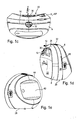
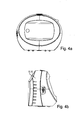
- Figures 1 a to e show various views of a preferred embodiment of a wearable device for providing negative pressure for medical applications
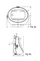
- FIGS. 2 a to e show different views of a first housing part of the device according to FIG. 1 comprising a vacuum-generating device and control components;
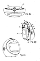
- FIGS. 3a to 1 show various views of a second housing part of the device according to FIG. 1 forming a container for receiving body fluids;
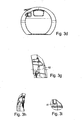
- Figures 4a to e Figures 1a to e corresponding views of another embodiment of a device, wherein the second housing part is dimensioned larger than in the apparatus according to Figures 1a to e;
- Figure 5 is a sectional view through the device in the field of vacuum communication between the first and second housing part
- FIG. 6 shows a schematic representation of the first and second housing part with an indication of the control components.
- a portable device 2 for providing negative pressure for medical applications will be described with reference to the figures 1-5, but differ only in terms of sizing and training of a container for receiving body fluids to be described. Thereafter, the inventive design of the control components of the portable device 2 will be described with reference to FIG.
- Figures 1a to e show a first embodiment of a portable device 2 for providing negative pressure for medical applications.
- the device comprises a first housing part 4, in which a negative pressure generating device in the form of an air suction pump 90 shown in Figure 6 and electrical and electronic control components for the device are included in total, including batteries or preferably rechargeable batteries.
- a charging port for the batteries is designated by reference numeral 6.
- the device 2 comprises a second housing part 8, which forms a container 10 for receiving body fluids, in particular for receiving wound secretions extracted from a wound.
- the entire second housing part 8 is designed as a disposable disposable article.
- connection piece 12 is provided for a shown in Figure 6 shown suction line 82, which then leads, for example, when using the device 2 for negative pressure wounds to a wound pressure-tight sealing wound dressing 80 and there, for example via a port with the Wound space communicates to apply and maintain a vacuum in the wound space and to aspirate wound secretions into the container 10.
- the container 10 communicates with the suction pump.
- a connection 13 for an optional measuring or flushing channel which leads to the wound like the suction line, is shown. This connection passes through the second housing part 8 and opens into the first housing part 4, from where the measuring or flushing channel can be acted upon, for example, with air as flushing medium and / or a pressure in this measuring or flushing channel can be detected and evaluated.
- the housing parts 4 and 8 abut each other via a substantially vertical parting plane 14, which is indicated in different figures. If the device 2, as indicated in Figure 1a, is placed on a flat horizontal surface 16, the parting plane 14 is oriented substantially vertically. This means that the two housing parts 4, 8 are not inserted into each other or stacked on top of each other, but that they come to rest side by side in the intended assembled state of the device 2.
- the term of the parting plane 14 is therefore not to be understood in the sense that it must be a geometrically flat surface, which is directly apparent from the figures 2a to e, which show the first housing part 4 in different views.
- the second housing part 8 facing side 18 of the first housing part 4 is not flat, but formed with a plurality of protruding in the direction of the second housing part 8 elements.
- the first housing part 4 facing side 20 of the second housing part 8 is formed substantially complementary to the formation of the side 18 of the first housing part 4, so that the two housing parts 4, 8 can be joined together or attached to each other only in a correct manner.
- the two housing parts 4, 8 are overall disk-shaped, d. H. their width B in the horizontal direction and their height H in the vertical direction are each greater than their depth T in the horizontal direction and perpendicular to the width extension. This makes it possible that the device 2 in the depth direction can be designed and dimensioned in total so that it can be comfortably worn on the body of a user.
- the device 2 is designed such that the container parts 4, 8 arranged next to one another can be positioned on the body such that the second container part 8 faces the body, ie between the body and the first housing part 4, and the first housing part 4 lies against the body comes, so essentially forms the visible side of the device 2. Therefore, the body of the user facing side 22 of the second housing part 8 is rounded.
- the body-facing side 22 is concave in section with a horizontal plane and, in the case illustrated by way of example, comprises in sections a radius of curvature R of, for example, 368 mm (FIGS. 1c, 3f).
- the body-facing side 22 is also formed concave when viewed in section with a vertical plane and there has a radius of curvature R of 750 mm by way of example ( Figure 1d). In this way, the device 2 can be ergonomically arranged and wear in the hip area of a user.
- the second housing part 8 on its body-facing side 22 in an upper region and also laterally a bevel 24 away from the body of the user in the direction of the first housing part 4 or toward side walls 26 or a peripheral end of the disc shape of second housing part 8 includes.
- the chamfer 24 is formed circumferentially in the example shown; it extends from the stand side 28 from bottom to top, there arcuate to the other side and then back down to the stand side 28 back.
- a manually operable actuator 32 for example in the form of a stylus, which acts on a locking or locking means 34 (see Figures 2b and 2d).
- a locking or locking means 34 see Figures 2b and 2d.
- the second housing part 8 is slightly obliquely from behind and from above with its lower edge on two a pivot point forming pin 33 (Figure 2d) of the first housing part 4 is placed.
- a recessed area 35 (FIG. 3 a) for receiving the pin 33 is formed in the second housing part at the lower edge.
- a body facing away visible side 38 of the first housing part 4 is slightly inclined to the vertical, so that the disc shape tapers upwards. In this way, an easier inspection of the visible side 38 is given.
- There controls 40 and display elements 42 are provided in particular in the form of a touch screen with a switching film. Essentially the entire visible side 38 is covered or formed by a planar cover 44, so that no dirt-retaining joints are formed in the region of the operating elements 40.
- a insertion slot 46 for insertion and releasable fixing a fastener in particular and preferably in the form of a flexible belt, or a strap or a tab on / the example a belt or a shoulder strap can be attached, or in any other form. It proves to be advantageous that this fastener can be detached from the housing parts 4, 8 and thus does not interfere when the device 2 in stationary operation, ie standing on a preferably flat pad 16 is used, such as when a patient hereby treated resting in a hospital bed.
- means 48 are indicated on the side 18 of the first housing part 4, at which means the fastening means inserted into the insertion slot 46 can be fixed or held.
- FIGS. 4a to e differs from the embodiment illustrated in FIG. 3 in that the second housing part 8 and the container 10 formed by it are designed to have a larger volume.
- the bevel in the upper region of the body-facing side 22 of the second housing part 8, where the recessed grip 30 is formed, is inclined somewhat more away from the user's body. In this way, even better access is possible.
- This larger second housing part 8 is more suitable for a stationary operation of the device 2; he could this also have an outwardly convex curved side 22 or even more expansive than those shown in Figures 4.
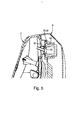
- FIG. 5 shows in detail the formation of the vacuum communication between the interior of the container 10 forming the second housing part 8 and the first housing part 4.
- the suction side of a vacuum generating device leads to the conically shaped connecting means 36, which is tapered in the direction of the second Housing part 8 tapers.
- an at least slightly yielding mating connection means 50 of the second housing part 8 are sealingly applied, which in the example shown has a circular opening 52 which is bounded by a resilient sealing lip 54.
- This counter-connection means 50 opens into the interior of the second housing part 8.
- a filter receiving means 56 for a filter 58 which is formed in the example shown as a cup-shaped filter and prevents bacteria from being sucked into the first housing part 4. It can readily be seen that, when the two housing parts 4, 8 move towards each other, the connecting means 36 of the first housing part 4 forms a pressure communication sealed to the outside with the counter-connection means 50 of the second housing part 8.
- connection 13 for a measuring or flushing channel and the associated connection means 60 which is likewise designed as an exemplary cone, is formed on the first housing part 4.
- a coupling or sleeve part (not shown) can be inserted into the through-opening 62 in the second housing part 8, which then forms the connection 13 for the measuring or flushing channel shown in FIG.
- This coupling or tulle part can then be pressure-tightly coupled to the cone-shaped connecting means 60.
- a fluid medium in particular air or a rinsing liquid
- a metering or flushing line and the suction line as disposable disposable components are accessory components to the second housing part; they are disposed of with the user after use.
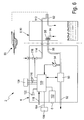
- Figure 6 shows the previously described or a similar device 2 for providing negative pressure for medical applications in a purely schematic representation, wherein corresponding reference numerals are used for corresponding components. In Figure 6, however, only the relevant components for the following description of the operation are shown. It can be seen schematically a in Figure 6 only indicated negative pressure to be treated wound with a vacuum-tight wound dressing 80, to which the opening out of the container 10 suction line 82 leads. From the container 10, another line section 84 leads through the already mentioned filter 58 through to the outside. When the container 10 or the first housing part 8 is brought into its operating position on the first or base housing part 4 of the device 2, the line section 84 is coupled to a further line section 88 within the first housing part, which leads to the suction side of the suction pump 90.
- the suction pump 90 is thus placed over the line sections 88, 84, a negative pressure to the container 10 and the suction line 82 and the air sucked from there via a discharge line 92 to the environment, additionally provided not shown silencer elements and optionally further filters could be.
- a pressure sensor 94 for measuring the pressure in the line section 88 between the container 10 and suction pump 90 is provided. Its signals are given to a programmable electronic control device, generally designated by reference numeral 100, which controls the device 2 as a whole. Also shown is the charging connection 6 already mentioned at the outset for batteries housed in a compartment 102 and a connection 104 for a schematically indicated power supply unit 106. Reference symbol 108 denotes a display unit with a preferably provided capacitive switching foil, via which the operation of the device is executable in total. The electrical connection to the electronic control device 100 is only indicated via electrical lines 110.
- the control of the suction pump 90 is carried out by means of the signals of the pressure sensor 94, a pressure or negative pressure control by known control and regulating mechanisms (target / actual control mechanisms) is executed, so that in the line section 88th the currently selected program corresponding pressure value is adjusted.
- an additional rinsing or ventilation line 112 is shown, which only passes through the container 10 in the exemplary case and, like the suction line 82, leads to the wound cover 80.
- this purge line 112 communicates with a provided in the first housing part 4 line section 114 in which an electromagnetically actuated valve 116 is provided, which is actuated by the electronic control device 100 and in the open state
- Line section 114 connects with the atmospheric air, so that an air flow can be generated via the purge line 112 in the direction of the wound.
- the device 2 and its electronic control device 100 also have a data interface 118, preferably a USB interface, by means of which the electronic control device 100 or its mode of operation can be programmed.
- a data interface 118 preferably a USB interface
- the electronic control device 100 is designed so that it permanently deactivates the vacuum-generating suction pump 90 when a detected by the signals of the pressure sensor 94 pressure change rate ( ⁇ p / .DELTA.t) in the direction of decreasing negative pressure, that is in the direction of increasing absolute pressure exceeds a predetermined threshold , This is due in the vast majority of cases to the intended or unintentional solution of the container 10 from the first or base housing part 4.
- This state of deactivation of the pressure control mode or of the suction pump 90 is then output visually via the display unit, optionally also an acoustic signal can be output via a loudspeaker 120 additionally or alternatively.
- the electronic control device 100 at a negative pressure increase in the line section 88 between the container 10 and suction pump 90 which, for example, indicate an increasing filling of the container, not deactivated, the suction pump, but continues the predetermined vacuum control operation.
- this vacuum increase that is, the decrease of the absolute pressure, due only to the fact that briefly blocked due to a tilt of the container 10 by the mobility of the user, the liquid-tight filter 58 without the container 10 is already filled so that a container change is displayed or there is another short-term blocking or pinching of a conduit means.
Abstract
Description
Claims (11)
- Tragbare Vorrichtung (2) zur Bereitstellung von Unterdruck zur medizinischen Unterdruckbehandlung von Wunden am menschlichen oder tierischen Körper, umfassend eine unterdruckerzeugende Saugpumpe (90) in einem ersten Gehäuseteil (4) der Vorrichtung, einen Behälter (10) zur Aufnahme von Körperflüssigkeiten, insbesondere von aus einer Wunde abgesaugten Wundsekreten, wobei der Behälter (10) lösbar an dem ersten Gehäuseteil (4) der Vorrichtung befestigbar ist und im befestigten Zustand von der Saugpumpe (90) mit Unterdruck beaufschlagbar ist, und wobei am Behälter (10) ein Anschluss (12) für eine zum Körper führende Saugleitung (82) vorgesehen ist, so dass eine Unterdruckkommunikation zwischen der Saugpumpe (90), dem Behälter (10) und der zum Körper führenden Saugleitung (82) herstellbar ist, einen Drucksensor (94), welcher zur Messung des Drucks in einem Leitungsabschnitt (88) zwischen dem Behälter (10) und der Saugpumpe (90) angeordnet ist, eine programmierbare elektronische Steuereinrichtung (100), welche mindestens unter Berücksichtigung von vorgegebenen und/oder vorgebbaren Parametern und von durch den Drucksensor (94) gemessenen Druckwerten die Saugpumpe (90) ansteuern kann, dadurch gekennzeichnet, dass die elektronische Steuereinrichtung (100) so ausgebildet ist, dass sie die Saugpumpe (90) deaktiviert, wenn, ausgehend von einem laufenden Unterdruckregelbetrieb, eine mittels der Signale des Drucksensors (94) festgestellte Druckänderungsrate (Δp/Δt) in Richtung abnehmenden Unterdrucks einen vorgegebenen Schwellwert übersteigt.Portable device (2) for providing negative pressure for the medical negative pressure treatment of wounds on the human or animal body, comprising a vacuum-generating suction pump (90) in a first housing part (4) of the device, a container (10) for receiving body fluids, in particular from Wound secretions sucked from a wound, the container (10) being releasably attachable to the first housing part (4) of the device and being subjected to negative pressure by the suction pump (90) in the attached state, and a connection (12) being provided on the container (10). is provided for a suction line leading to the body (82), so that a vacuum communication between the suction pump (90), the container (10) and the body leading to the suction line (82) can be produced, a pressure sensor (94), which for measuring the Pressure in a line section (88) between the container (10) and the suction pump (90) is arranged, a programmable elektronisc The control device (100), which can control the suction pump (90) at least taking into account predetermined and / or predefinable parameters and pressure values measured by the pressure sensor (94), characterized in that the electronic control device (100) is designed such that it deactivates the suction pump (90), if, starting from a current vacuum control operation, a pressure change rate (Δp / Δt) determined by means of the signals of the pressure sensor (94) in the direction of decreasing negative pressure exceeds a predetermined threshold value.
- Vorrichtung nach Anspruch 1, dadurch gekennzeichnet, dass der Schwellwert 40 mmHg/s beträgt oder höher ist.Device according to claim 1, characterized in that the threshold value is 40 mmHg / s or higher.
- Vorrichtung nach einem oder mehreren der vorstehenden Ansprüche, dadurch gekennzeichnet, dass eine Ausgabe- oder Anzeigeeinrichtung (108) zur Erzeugung eines Signals vorgesehen ist, welches einen abrupten Druckanstieg mit einer Druckänderungsrate oberhalb des Schwellwerts visuell oder akustisch vermittelt.Device according to one or more of the preceding claims, characterized in that an output or display device (108) is provided for generating a signal which provides an abrupt increase in pressure visually or acoustically at a pressure change rate above the threshold value.
- Vorrichtung nach einem oder mehreren der vorstehenden Ansprüche, dadurch gekennzeichnet, dass eine Ausgabe- oder Anzeigeeinrichtung vorgesehen ist, welche zur drahtlosen Übermittlung eines Signals an einen externen Empfänger ausgebildet ist, welches den abrupten Druckanstieg mit einer Druckänderungsrate oberhalb des Schwellwerts an einen externen Empfänger vermittelt.Device according to one or more of the preceding claims, characterized in that an output or display device is provided, which is designed for wireless transmission of a signal to an external receiver, which mediates the abrupt increase in pressure at a pressure change rate above the threshold value to an external receiver.
- Vorrichtung nach einem oder mehreren der vorstehenden Ansprüche, gekennzeichnet durch ein durch die elektronische Steuereinrichtung (100) steuerbares Belüftungsventil (116), welches über eine zusätzlich zur Saugleitung vorgesehene Belüftungsleitung (112) mit dem Wundraum verbindbar ist, sodass der Wundraum mit Außenluft belüftet werden kann. Device according to one or more of the preceding claims, characterized by a ventilation valve (116) which can be controlled by the electronic control device (100), which can be connected to the wound space via an aeration line (112) provided in addition to the suction line, so that the wound space can be ventilated with outside air ,
- Vorrichtung nach einem oder mehreren der vorstehenden Ansprüche, gekennzeichnet durch eine durch die elektronische Steuereinrichtung (100) steuerbare Einrichtung zum Zuführen einer Spülflüssigkeit oder eines sonstigen Fluids, welche über eine zusätzlich zur Saugleitung vorgesehene Spülleitung mit dem Wundraum verbindbar ist, so dass Spülflüssigkeit oder ein sonstiges Fluid in den Wundraum zugeführt werden kann.Device according to one or more of the preceding claims, characterized by a controllable by the electronic control device (100) means for supplying a rinsing liquid or other fluid, which is connectable via a additionally provided to the suction line flushing line with the wound space, so that rinsing liquid or another Fluid can be supplied to the wound room.
- Vorrichtung nach Anspruch 6, dadurch gekennzeichnet, dass die elektronische Steuereinrichtung (100) so ausgebildet ist, dass sie beim Deaktivieren der Saugpumpe auch die Einrichtung zum Zuführen einer Spülflüssigkeit oder eines sonstigen Fluids deaktiviert.Apparatus according to claim 6, characterized in that the electronic control device (100) is designed so that it also deactivates the means for supplying a rinsing liquid or other fluid when deactivating the suction pump.
- Vorrichtung nach einem oder mehreren der vorstehenden Ansprüche, dadurch gekennzeichnet, dass die elektronische Steuereinrichtung (100) so ausgebildet ist, dass sie bei zutreffender oder unzutreffender Erkennung eines Behälter-voll-Zustands die Saugpumpe (90) nicht deaktiviert, sondern den vorgegebenen Unterdruckregelbetrieb fortsetzt.Device according to one or more of the preceding claims, characterized in that the electronic control device (100) is designed so that it does not deactivate the suction pump (90) in case of correct or incorrect detection of a container full condition, but continues the predetermined vacuum control operation.
- Vorrichtung nach einem oder mehreren der vorstehenden Ansprüche, dadurch gekennzeichnet, dass die elektronische Steuereinrichtung (100) so ausgebildet ist, dass sie bei einem Unterdruckanstieg, das heißt bei einer Abnahme des absoluten Drucks in dem Leitungsabschnitt (88) zwischen Behälter (10) und Saugpumpe (90), der insbesondere auf eine zunehmende Befüllung des Behälters schließen lässt, die Saugpumpe (90) nicht deaktiviert, sondern den vorgegebenen Unterdruckregelbetrieb fortsetzt.Device according to one or more of the preceding claims, characterized in that the electronic control device (100) is designed so that it increases at a negative pressure, that is at a decrease in the absolute pressure in the line section (88) between the container (10) and suction (90), which in particular suggests an increasing filling of the container, the suction pump (90) is not deactivated, but continues the predetermined vacuum control operation.
- Verfahren zum Betreiben einer Vorrichtung nach einem oder mehreren der vorstehenden Ansprüche, dadurch gekennzeichnet, dass mittels der elektronischen Steuereinrichtung (100) anhand der Signale des Drucksensors (94) eine Druckänderungsrate (Δp/Δt) bestimmt wird und dass bei abnehmendem Unterdruck, d.h. zunehmendem absolutem Druck, die Druckänderungsrate (Δp/Δt) mit einem in der Steuereinrichtung (100) hinterlegten Schwellwert verglichen wird, und dass bei Überschreiten des Schwellwerts die Saugpumpe (90) deaktiviert wird.Method for operating a device according to one or more of the preceding claims, characterized in that a pressure change rate (Δp / Δt) is determined by means of the electronic control device (100) on the basis of the signals of the pressure sensor (94) and that as the negative pressure, i. increasing absolute pressure, the pressure change rate (.DELTA.p / .DELTA.t) is compared with a stored in the control device (100) threshold value, and that when the threshold value is exceeded, the suction pump (90) is deactivated.
- Verfahren nach Anspruch 10, dadurch gekennzeichnet, dass bei einem Unterdruckanstieg, das heißt bei einer Abnahme des absoluten Drucks in dem Leitungsabschnitt (88) zwischen Behälter (10) und Saugpumpe (90), der insbesondere auf eine zunehmende Befüllung des Behälters schließen lässt, die Saugpumpe (90) nicht deaktiviert wird, sondern der vorgegebene Unterdruckregelbetrieb fortgesetzt wird.A method according to claim 10, characterized in that at a negative pressure increase, that is at a decrease in the absolute pressure in the line section (88) between the container (10) and suction pump (90), which in particular suggests an increasing filling of the container Suction pump (90) is not deactivated, but the predetermined vacuum control operation is continued.
Priority Applications (4)
| Application Number | Priority Date | Filing Date | Title |
|---|---|---|---|
| EP12713047.4A EP2680895B1 (en) | 2011-05-13 | 2012-03-27 | Device for providing vacuum for the vacuum treatment of wounds |
| CN201280022732.XA CN103561792A (en) | 2011-05-13 | 2012-03-27 | Device for providing vacuum for the vacuum treatment of wounds |
| BR112013027945A BR112013027945A2 (en) | 2011-05-13 | 2012-03-27 | vacuum supply device for wound vacuum treatment |
| RU2013154360/14A RU2013154360A (en) | 2011-05-13 | 2012-03-27 | DEVICE FOR CREATING A VACUUM INTENDED FOR VACUUMING OF THE RAS |
Applications Claiming Priority (2)
| Application Number | Priority Date | Filing Date | Title |
|---|---|---|---|
| DE102011075844A DE102011075844A1 (en) | 2011-05-13 | 2011-05-13 | Device for providing negative pressure for the negative pressure treatment of wounds |
| DE102011075844.5 | 2011-05-13 |
Publications (1)
| Publication Number | Publication Date |
|---|---|
| WO2012156140A1 true WO2012156140A1 (en) | 2012-11-22 |
Family
ID=45937293
Family Applications (1)
| Application Number | Title | Priority Date | Filing Date |
|---|---|---|---|
| PCT/EP2012/055438 WO2012156140A1 (en) | 2011-05-13 | 2012-03-27 | Device for providing vacuum for the vacuum treatment of wounds |
Country Status (7)
| Country | Link |
|---|---|
| US (1) | US8540688B2 (en) |
| EP (1) | EP2680895B1 (en) |
| CN (1) | CN103561792A (en) |
| BR (1) | BR112013027945A2 (en) |
| DE (1) | DE102011075844A1 (en) |
| RU (1) | RU2013154360A (en) |
| WO (1) | WO2012156140A1 (en) |
Cited By (8)
| Publication number | Priority date | Publication date | Assignee | Title |
|---|---|---|---|---|
| EP2680895B1 (en) | 2011-05-13 | 2015-08-12 | Paul Hartmann AG | Device for providing vacuum for the vacuum treatment of wounds |
| DE102014106518A1 (en) | 2014-05-09 | 2015-11-12 | Paul Hartmann Ag | Foam wound dressing for negative pressure therapy |
| DE102014116910A1 (en) | 2014-11-19 | 2016-05-19 | Paul Hartmann Ag | Electronic fluid sensor for negative pressure therapy device |
| DE102014116912A1 (en) | 2014-11-19 | 2016-05-19 | Paul Hartmann Ag | Fluid indicator for negative pressure device |
| WO2018029229A1 (en) | 2016-08-10 | 2018-02-15 | Paul Hartmann Ag | Holding loop for suction bodies for endoluminal negative pressure therapy |
| DE102016114817A1 (en) | 2016-08-10 | 2018-02-15 | Paul Hartmann Ag | Medical kit for use in the negative pressure therapy of endoluminal wound sites in the area of the gastrointestinal tract |
| WO2018029231A1 (en) | 2016-08-10 | 2018-02-15 | Paul Hartmann Ag | Suction element for endoluminal negative pressure therapy |
| EP3501560A1 (en) | 2017-12-21 | 2019-06-26 | Paul Hartmann AG | Method for operating a suction therapy system |
Families Citing this family (65)
| Publication number | Priority date | Publication date | Assignee | Title |
|---|---|---|---|---|
| WO2009066106A1 (en) | 2007-11-21 | 2009-05-28 | Smith & Nephew Plc | Wound dressing |
| GB201015656D0 (en) | 2010-09-20 | 2010-10-27 | Smith & Nephew | Pressure control apparatus |
| CA3089920C (en) | 2010-10-12 | 2024-01-09 | Smith & Nephew, Inc. | A medical device configured to communicate with a remote computer system |
| GB201020005D0 (en) | 2010-11-25 | 2011-01-12 | Smith & Nephew | Composition 1-1 |
| EP2643412B1 (en) | 2010-11-25 | 2016-08-17 | Smith & Nephew PLC | Composition i-ii and products and uses thereof |
| US9302034B2 (en) | 2011-04-04 | 2016-04-05 | Smith & Nephew, Inc. | Negative pressure wound therapy dressing |
| GB201108229D0 (en) | 2011-05-17 | 2011-06-29 | Smith & Nephew | Tissue healing |
| US9084845B2 (en) | 2011-11-02 | 2015-07-21 | Smith & Nephew Plc | Reduced pressure therapy apparatuses and methods of using same |
| MX2014011314A (en) | 2012-03-20 | 2014-10-17 | Smith & Nephew | Controlling operation of a reduced pressure therapy system based on dynamic duty cycle threshold determination. |
| US9427505B2 (en) | 2012-05-15 | 2016-08-30 | Smith & Nephew Plc | Negative pressure wound therapy apparatus |
| WO2013175306A2 (en) | 2012-05-23 | 2013-11-28 | Smith & Nephew Plc | Apparatuses and methods for negative pressure wound therapy |
| DK2879636T3 (en) | 2012-08-01 | 2017-06-19 | Smith & Nephew | Wound dressing |
| EP3406231B1 (en) | 2012-08-01 | 2022-04-13 | Smith & Nephew plc | Wound dressing and method of treatment |
| EP2882470B1 (en) * | 2012-08-13 | 2020-03-18 | KCI Licensing, Inc. | Intelligent therapy system with evaporation management |
| RU2015143724A (en) | 2013-03-14 | 2017-04-17 | Смит Энд Нефью Инк. | SYSTEMS AND METHODS OF APPLICATION OF THERAPY USING REDUCED PRESSURE |
| US9737649B2 (en) | 2013-03-14 | 2017-08-22 | Smith & Nephew, Inc. | Systems and methods for applying reduced pressure therapy |
| US20160120706A1 (en) | 2013-03-15 | 2016-05-05 | Smith & Nephew Plc | Wound dressing sealant and use thereof |
| BR112015020855A2 (en) | 2013-03-15 | 2017-07-18 | Smith & Nephew | wound dressing and treatment method |
| US10695226B2 (en) | 2013-03-15 | 2020-06-30 | Smith & Nephew Plc | Wound dressing and method of treatment |
| CN105916530B (en) | 2013-08-13 | 2019-09-17 | 史密夫和内修有限公司 | System and method for application decompression treatment |
| AU359280S (en) * | 2014-04-30 | 2014-12-08 | Talley Group Ltd | Negative pressure wound therapy pump |
| USD764048S1 (en) * | 2014-05-28 | 2016-08-16 | Smith & Nephew, Inc. | Device for applying negative pressure to a wound |
| USD764653S1 (en) | 2014-05-28 | 2016-08-23 | Smith & Nephew, Inc. | Canister for collecting wound exudate |
| USD764047S1 (en) * | 2014-05-28 | 2016-08-16 | Smith & Nephew, Inc. | Therapy unit assembly |
| USD765830S1 (en) * | 2014-06-02 | 2016-09-06 | Smith & Nephew, Inc. | Therapy unit assembly |
| WO2015193257A1 (en) | 2014-06-18 | 2015-12-23 | Smith & Nephew Plc | Wound dressing |
| AU2014402290B2 (en) | 2014-07-31 | 2020-05-21 | Smith & Nephew, Inc. | Systems and methods for applying reduced pressure therapy |
| WO2016103032A1 (en) | 2014-12-22 | 2016-06-30 | Smith & Nephew Plc | Negative pressure wound therapy apparatus and methods |
| CA2972701A1 (en) | 2014-12-30 | 2016-07-07 | Smith & Nephew, Inc. | Systems and methods for applying reduced pressure therapy |
| JP6698091B2 (en) | 2014-12-30 | 2020-05-27 | スミス アンド ネフュー インコーポレイテッド | System and method for delivering reduced pressure therapy |
| US11179506B2 (en) * | 2015-02-27 | 2021-11-23 | Cork Medical, Llc | Negative pressure wound therapy pump and canister |
| USD750222S1 (en) * | 2015-04-27 | 2016-02-23 | Koge Micro Tech Co., Ltd | Wound therapy device |
| USD753810S1 (en) * | 2015-04-27 | 2016-04-12 | Koge Micro Tech Co., Ltd | Wound therapy device |
| USD832999S1 (en) * | 2015-05-05 | 2018-11-06 | Medaxis Ag | Pump for debridement by water jet |
| RU2610996C2 (en) * | 2015-08-06 | 2017-02-17 | Федеральное государственное автономное образовательное учреждение высшего образования "Белгородский государственный национальный исследовательский университет" (НИУ "БелГУ") | Method of increasing strength properties of welded joints made by friction welding with mixing |
| CA2995469C (en) | 2015-08-13 | 2023-10-03 | Smith & Nephew, Inc. | Systems and methods for applying reduced pressure therapy |
| EP3347068B1 (en) | 2015-09-11 | 2021-07-28 | Smith & Nephew, Inc | Systems and methods for applying reduced negative pressure therapy |
| CN108292529A (en) | 2015-10-07 | 2018-07-17 | 史密夫和内修有限公司 | System and method for application decompression treatment |
| CA3009878A1 (en) | 2015-12-30 | 2017-07-06 | Smith & Nephew Plc | Negative pressure wound therapy apparatus |
| EP3187202B1 (en) | 2015-12-30 | 2019-09-25 | Paul Hartmann AG | Devices for controlling a negative pressure wound therapy system |
| EP3187204B1 (en) | 2015-12-30 | 2020-07-15 | Paul Hartmann AG | Methods and devices for controlling negative pressure wound therapy |
| ES2729154T5 (en) | 2015-12-30 | 2022-12-01 | Hartmann Paul Ag | Procedures and devices to control negative pressure at a wound site |
| EP3187206B1 (en) | 2015-12-30 | 2019-03-13 | Paul Hartmann AG | Methods and devices for negative pressure wound therapy |
| EP3187205B1 (en) | 2015-12-30 | 2021-01-27 | Paul Hartmann AG | Methods and devices for performing a negative pressure wound therapy |
| US11090196B2 (en) | 2015-12-30 | 2021-08-17 | Smith & Nephew Plc | Absorbent negative pressure wound therapy dressing |
| EP3413945A1 (en) | 2016-02-12 | 2018-12-19 | Smith & Nephew, Inc | Systems and methods for detecting operational conditions of reduced pressure therapy |
| JP1586116S (en) | 2016-02-29 | 2017-09-19 | ||
| US11771820B2 (en) | 2016-03-04 | 2023-10-03 | Smith & Nephew Plc | Negative pressure wound therapy apparatus for post breast surgery wounds |
| WO2017197357A1 (en) | 2016-05-13 | 2017-11-16 | Smith & Nephew Plc | Automatic wound coupling detection in negative pressure wound therapy systems |
| US11369730B2 (en) | 2016-09-29 | 2022-06-28 | Smith & Nephew, Inc. | Construction and protection of components in negative pressure wound therapy systems |
| US11806217B2 (en) | 2016-12-12 | 2023-11-07 | Smith & Nephew Plc | Wound dressing |
| EP3582821A1 (en) * | 2017-02-15 | 2019-12-25 | Smith&nephew Pte. Limited | Negative pressure wound therapy apparatuses and methods for using the same |
| AU2018285235B2 (en) | 2017-06-14 | 2023-11-02 | T.J.Smith & Nephew, Limited | Negative pressure wound therapy apparatus |
| US11712508B2 (en) | 2017-07-10 | 2023-08-01 | Smith & Nephew, Inc. | Systems and methods for directly interacting with communications module of wound therapy apparatus |
| US20210361853A1 (en) * | 2017-08-17 | 2021-11-25 | Kci Licensing, Inc. | Apparatuses and methods for removing fluid from a wound utilizing controlled airflow |
| EP3687592A1 (en) | 2017-09-29 | 2020-08-05 | T.J. Smith & Nephew, Limited | Negative pressure wound therapy apparatus with removable panels |
| GB201813282D0 (en) | 2018-08-15 | 2018-09-26 | Smith & Nephew | System for medical device activation and opertion |
| WO2019157466A1 (en) | 2018-02-12 | 2019-08-15 | Healyx Labs, Inc. | Negative pressure wound therapy systems, devices, and methods |
| GB201804347D0 (en) | 2018-03-19 | 2018-05-02 | Smith & Nephew Inc | Securing control of settings of negative pressure wound therapy apparatuses and methods for using the same |
| EP3787704A1 (en) | 2018-04-30 | 2021-03-10 | Smith & Nephew Asia Pacific Pte Limited | Systems and methods for controlling dual mode negative pressure wound therapy apparatus |
| GB201808438D0 (en) | 2018-05-23 | 2018-07-11 | Smith & Nephew | Systems and methods for determining blockages in a negative pressure wound therapy system |
| RU2687567C1 (en) * | 2018-07-09 | 2019-05-15 | Павел Львович Федоров | Instrument for treating infected and purulent wounds |
| GB201820668D0 (en) | 2018-12-19 | 2019-01-30 | Smith & Nephew Inc | Systems and methods for delivering prescribed wound therapy |
| US11890407B2 (en) * | 2020-03-05 | 2024-02-06 | Deroyal Industries, Inc. | Negative pressure wound therapy canister connection system |
| DE212021000543U1 (en) | 2021-01-30 | 2024-01-24 | Surinder Kumar Sharma | Vacuum system |
Citations (11)
| Publication number | Priority date | Publication date | Assignee | Title |
|---|---|---|---|---|
| EP0777504A1 (en) | 1994-08-22 | 1997-06-11 | Kinetic Concepts, Inc. | Wound drainage equipment |
| EP0988865A2 (en) * | 1995-04-11 | 2000-03-29 | MACKOOL, Richard J. | Apparatus for controlling the temperature of a surgical instrument |
| WO2003005943A2 (en) * | 2001-07-12 | 2003-01-23 | Hill-Rom Services, Inc. | Control of vacuum level rate of change |
| US20040073151A1 (en) | 2002-09-03 | 2004-04-15 | Weston Richard Scott | Reduced pressure treatment system |
| WO2007030599A2 (en) | 2005-09-07 | 2007-03-15 | Tyco Healthcare Group Lp | Self contained wound dressing apparatus |
| EP1905465A1 (en) | 2006-09-28 | 2008-04-02 | Tyco Healthcare Group LP | Portable wound therapy system |
| US20090012441A1 (en) * | 2007-07-06 | 2009-01-08 | Sharon Mulligan | Subatmospheric pressure wound therapy dressing |
| WO2009047524A2 (en) | 2007-10-10 | 2009-04-16 | Talley Group Limited | Medical apparatus for use in negative pressure wound therapy |
| US20110008179A1 (en) * | 2007-07-02 | 2011-01-13 | Smith & Nephew Plc | Pressure control |
| DE102009038130A1 (en) | 2009-08-12 | 2011-02-17 | ATMOS Medizin Technik GmbH & Co. KG | A user portable device for providing negative pressure for medical applications |
| DE102009038131A1 (en) | 2009-08-12 | 2011-02-17 | ATMOS Medizin Technik GmbH & Co. KG | A user portable device for providing negative pressure for medical applications |
Family Cites Families (19)
| Publication number | Priority date | Publication date | Assignee | Title |
|---|---|---|---|---|
| GB9523253D0 (en) | 1995-11-14 | 1996-01-17 | Mediscus Prod Ltd | Portable wound treatment apparatus |
| US6458109B1 (en) | 1998-08-07 | 2002-10-01 | Hill-Rom Services, Inc. | Wound treatment apparatus |
| GB9822341D0 (en) | 1998-10-13 | 1998-12-09 | Kci Medical Ltd | Negative pressure therapy using wall suction |
| US6764462B2 (en) | 2000-11-29 | 2004-07-20 | Hill-Rom Services Inc. | Wound treatment apparatus |
| US8409214B2 (en) | 2009-01-22 | 2013-04-02 | Meditech Development Incorporated | Portable regulated vacuum pump for medical procedures |
| US7004915B2 (en) | 2001-08-24 | 2006-02-28 | Kci Licensing, Inc. | Negative pressure assisted tissue treatment system |
| US7625362B2 (en) | 2003-09-16 | 2009-12-01 | Boehringer Technologies, L.P. | Apparatus and method for suction-assisted wound healing |
| ES2901826T3 (en) * | 2004-11-05 | 2022-03-23 | Convatec Technologies Inc | Vacuum Wound Care Module |
| DE102005014420A1 (en) | 2005-03-24 | 2006-09-28 | Inmeditec Medizintechnik Gmbh | Vacuum therapy device |
| MX2009002948A (en) | 2006-09-19 | 2009-03-31 | Kci Licensing Inc | Reduced pressure treatment system having blockage clearing and dual-zone pressure protection capabilities. |
| AU2007300703A1 (en) | 2006-09-26 | 2008-04-03 | Boehringer Technologies L.P. | Pump system for negative pressure wound therapy |
| US8323264B2 (en) * | 2006-10-17 | 2012-12-04 | Bluesky Medical Group, Inc. | Auxiliary powered negative pressure wound therapy apparatuses and methods |
| CA2675263C (en) * | 2007-02-20 | 2012-01-03 | Kci Licensing, Inc. | System and method for distinguishing leaks from a disengaged canister condition in a reduced pressure treatment system |
| AU2009204140B9 (en) * | 2008-01-08 | 2014-03-13 | Smith & Nephew Plc | Sustained variable negative pressure wound treatment and method of controlling same |
| AU2009257390B2 (en) * | 2008-06-12 | 2014-09-04 | Medtronic Xomed, Inc. | Method for treating chronic wounds with an extracellular polymeric substance solvating system |
| AU2009293176B2 (en) | 2008-09-18 | 2015-07-02 | Solventum Intellectual Properties Company | A system and method for delivering reduced pressure to subcutaneous tissue |
| US20100318071A1 (en) * | 2009-06-10 | 2010-12-16 | Tyco Healthcare Group Lp | Fluid Collection Canister Including Canister Top with Filter Membrane and Negative Pressure Wound Therapy Systems Including Same |
| US20110106058A1 (en) * | 2009-10-29 | 2011-05-05 | Pal Svedman | Adhesive Flange Attachment Reinforcer For Suction Port |
| DE102011075844A1 (en) | 2011-05-13 | 2012-11-15 | Paul Hartmann Ag | Device for providing negative pressure for the negative pressure treatment of wounds |
-
2011
- 2011-05-13 DE DE102011075844A patent/DE102011075844A1/en not_active Withdrawn
-
2012
- 2012-03-27 CN CN201280022732.XA patent/CN103561792A/en active Pending
- 2012-03-27 WO PCT/EP2012/055438 patent/WO2012156140A1/en active Application Filing
- 2012-03-27 RU RU2013154360/14A patent/RU2013154360A/en not_active Application Discontinuation
- 2012-03-27 BR BR112013027945A patent/BR112013027945A2/en not_active IP Right Cessation
- 2012-03-27 EP EP12713047.4A patent/EP2680895B1/en active Active
- 2012-05-11 US US13/469,106 patent/US8540688B2/en not_active Expired - Fee Related
Patent Citations (12)
| Publication number | Priority date | Publication date | Assignee | Title |
|---|---|---|---|---|
| EP0777504A1 (en) | 1994-08-22 | 1997-06-11 | Kinetic Concepts, Inc. | Wound drainage equipment |
| EP0777504B1 (en) | 1994-08-22 | 1998-10-21 | Kinetic Concepts, Inc. | Wound drainage equipment |
| EP0988865A2 (en) * | 1995-04-11 | 2000-03-29 | MACKOOL, Richard J. | Apparatus for controlling the temperature of a surgical instrument |
| WO2003005943A2 (en) * | 2001-07-12 | 2003-01-23 | Hill-Rom Services, Inc. | Control of vacuum level rate of change |
| US20040073151A1 (en) | 2002-09-03 | 2004-04-15 | Weston Richard Scott | Reduced pressure treatment system |
| WO2007030599A2 (en) | 2005-09-07 | 2007-03-15 | Tyco Healthcare Group Lp | Self contained wound dressing apparatus |
| EP1905465A1 (en) | 2006-09-28 | 2008-04-02 | Tyco Healthcare Group LP | Portable wound therapy system |
| US20110008179A1 (en) * | 2007-07-02 | 2011-01-13 | Smith & Nephew Plc | Pressure control |
| US20090012441A1 (en) * | 2007-07-06 | 2009-01-08 | Sharon Mulligan | Subatmospheric pressure wound therapy dressing |
| WO2009047524A2 (en) | 2007-10-10 | 2009-04-16 | Talley Group Limited | Medical apparatus for use in negative pressure wound therapy |
| DE102009038130A1 (en) | 2009-08-12 | 2011-02-17 | ATMOS Medizin Technik GmbH & Co. KG | A user portable device for providing negative pressure for medical applications |
| DE102009038131A1 (en) | 2009-08-12 | 2011-02-17 | ATMOS Medizin Technik GmbH & Co. KG | A user portable device for providing negative pressure for medical applications |
Cited By (13)
| Publication number | Priority date | Publication date | Assignee | Title |
|---|---|---|---|---|
| EP2680895B1 (en) | 2011-05-13 | 2015-08-12 | Paul Hartmann AG | Device for providing vacuum for the vacuum treatment of wounds |
| DE102014106518A1 (en) | 2014-05-09 | 2015-11-12 | Paul Hartmann Ag | Foam wound dressing for negative pressure therapy |
| DE102014116910A1 (en) | 2014-11-19 | 2016-05-19 | Paul Hartmann Ag | Electronic fluid sensor for negative pressure therapy device |
| DE102014116912A1 (en) | 2014-11-19 | 2016-05-19 | Paul Hartmann Ag | Fluid indicator for negative pressure device |
| EP3023111A1 (en) | 2014-11-19 | 2016-05-25 | Paul Hartmann AG | Liquid indicator for negative pressure therapy device |
| WO2016079075A1 (en) | 2014-11-19 | 2016-05-26 | Paul Hartmann Ag | Electronic liquid sensor for vacuum treatment device |
| WO2018029229A1 (en) | 2016-08-10 | 2018-02-15 | Paul Hartmann Ag | Holding loop for suction bodies for endoluminal negative pressure therapy |
| DE102016114817A1 (en) | 2016-08-10 | 2018-02-15 | Paul Hartmann Ag | Medical kit for use in the negative pressure therapy of endoluminal wound sites in the area of the gastrointestinal tract |
| DE102016114786A1 (en) | 2016-08-10 | 2018-02-15 | Paul Hartmann Ag | Barrel loop for absorbent bodies for endoluminal negative pressure therapy |
| WO2018029231A1 (en) | 2016-08-10 | 2018-02-15 | Paul Hartmann Ag | Suction element for endoluminal negative pressure therapy |
| DE102016114819A1 (en) | 2016-08-10 | 2018-02-15 | Paul Hartmann Ag | Absorbent body for endoluminal negative pressure therapy |
| EP3501560A1 (en) | 2017-12-21 | 2019-06-26 | Paul Hartmann AG | Method for operating a suction therapy system |
| DE102017131018A1 (en) | 2017-12-21 | 2019-06-27 | Paul Hartmann Ag | Method for operating a negative pressure therapy system |
Also Published As
| Publication number | Publication date |
|---|---|
| RU2013154360A (en) | 2015-06-20 |
| BR112013027945A2 (en) | 2017-01-17 |
| EP2680895A1 (en) | 2014-01-08 |
| EP2680895B1 (en) | 2015-08-12 |
| US8540688B2 (en) | 2013-09-24 |
| US20120289914A1 (en) | 2012-11-15 |
| CN103561792A (en) | 2014-02-05 |
| DE102011075844A1 (en) | 2012-11-15 |
Similar Documents
| Publication | Publication Date | Title |
|---|---|---|
| EP2680895B1 (en) | Device for providing vacuum for the vacuum treatment of wounds | |
| EP2707047B1 (en) | Device for providing vacuum for the medical vacuum treatment of wounds | |
| EP2464393B2 (en) | Device that can be worn on the body of a user and that provides vacuum for medical uses | |
| EP2464394B2 (en) | Device that can be worn on the body of a user and that provides vacuum for medical uses | |
| EP2673016B1 (en) | Device for providing a vacuum for the vacuum treatment of wounds, comprising a holding or carrying device | |
| EP2626049B1 (en) | Wound treatment device | |
| EP2729197B1 (en) | Thoracic drainage device having reduced counter-pressure | |
| EP1897568A1 (en) | Surgical system | |
| DE102010060543A1 (en) | Drainage device for wound treatment using negative pressure | |
| DE102015110432A1 (en) | Instillation adapter for a vacuum wound treatment system | |
| EP3160526B1 (en) | Device for the extraction and forwarding of blood | |
| EP2892581B1 (en) | Medical drainage tube | |
| EP3372256B1 (en) | Lumen detection method | |
| DE4016034A1 (en) | Medical equipment draining wounds by vacuum - has pressure sensor at low pressure side in regulating circuit for vacuum pump | |
| EP3023111A1 (en) | Liquid indicator for negative pressure therapy device | |
| WO2018036822A1 (en) | Device for the vacuum treatment of wounds on the human body | |
| DE102006054628B4 (en) | Surgical system | |
| EP3318226A1 (en) | Clean venturi aspiration | |
| DE102011052735A1 (en) | Medical drainage tube for treatment of wounds by low pressure produced by medical suction apparatus, has filter which communicates with air inlet opening formed in connection unit, and closure stopper for closing air inlet opening | |
| EP3878486A1 (en) | Device for vacuum treatment and instillation of wounds | |
| EP3501560A1 (en) | Method for operating a suction therapy system |
Legal Events
| Date | Code | Title | Description |
|---|---|---|---|
| 121 | Ep: the epo has been informed by wipo that ep was designated in this application |
Ref document number: 12713047 Country of ref document: EP Kind code of ref document: A1 |
|
| WWE | Wipo information: entry into national phase |
Ref document number: 2012713047 Country of ref document: EP |
|
| NENP | Non-entry into the national phase |
Ref country code: DE |
|
| ENP | Entry into the national phase |
Ref document number: 2013154360 Country of ref document: RU Kind code of ref document: A |
|
| REG | Reference to national code |
Ref country code: BR Ref legal event code: B01A Ref document number: 112013027945 Country of ref document: BR |
|
| ENP | Entry into the national phase |
Ref document number: 112013027945 Country of ref document: BR Kind code of ref document: A2 Effective date: 20131030 |