WO2013018861A1 - 医療用マニピュレータおよびその制御方法 - Google Patents
医療用マニピュレータおよびその制御方法 Download PDFInfo
- Publication number
- WO2013018861A1 WO2013018861A1 PCT/JP2012/069696 JP2012069696W WO2013018861A1 WO 2013018861 A1 WO2013018861 A1 WO 2013018861A1 JP 2012069696 W JP2012069696 W JP 2012069696W WO 2013018861 A1 WO2013018861 A1 WO 2013018861A1
- Authority
- WO
- WIPO (PCT)
- Prior art keywords
- unit
- input
- input unit
- grip
- medical manipulator
- Prior art date
Links
Images


Classifications
-
- G—PHYSICS
- G06—COMPUTING; CALCULATING OR COUNTING
- G06F—ELECTRIC DIGITAL DATA PROCESSING
- G06F3/00—Input arrangements for transferring data to be processed into a form capable of being handled by the computer; Output arrangements for transferring data from processing unit to output unit, e.g. interface arrangements
- G06F3/01—Input arrangements or combined input and output arrangements for interaction between user and computer
-
- A—HUMAN NECESSITIES
- A61—MEDICAL OR VETERINARY SCIENCE; HYGIENE
- A61B—DIAGNOSIS; SURGERY; IDENTIFICATION
- A61B17/00—Surgical instruments, devices or methods, e.g. tourniquets
- A61B17/28—Surgical forceps
- A61B17/29—Forceps for use in minimally invasive surgery
-
- A—HUMAN NECESSITIES
- A61—MEDICAL OR VETERINARY SCIENCE; HYGIENE
- A61B—DIAGNOSIS; SURGERY; IDENTIFICATION
- A61B17/00—Surgical instruments, devices or methods, e.g. tourniquets
- A61B17/32—Surgical cutting instruments
- A61B17/320016—Endoscopic cutting instruments, e.g. arthroscopes, resectoscopes
- A61B17/32002—Endoscopic cutting instruments, e.g. arthroscopes, resectoscopes with continuously rotating, oscillating or reciprocating cutting instruments
-
- A—HUMAN NECESSITIES
- A61—MEDICAL OR VETERINARY SCIENCE; HYGIENE
- A61B—DIAGNOSIS; SURGERY; IDENTIFICATION
- A61B18/00—Surgical instruments, devices or methods for transferring non-mechanical forms of energy to or from the body
- A61B18/04—Surgical instruments, devices or methods for transferring non-mechanical forms of energy to or from the body by heating
- A61B18/12—Surgical instruments, devices or methods for transferring non-mechanical forms of energy to or from the body by heating by passing a current through the tissue to be heated, e.g. high-frequency current
- A61B18/14—Probes or electrodes therefor
- A61B18/1402—Probes for open surgery
-
- A—HUMAN NECESSITIES
- A61—MEDICAL OR VETERINARY SCIENCE; HYGIENE
- A61B—DIAGNOSIS; SURGERY; IDENTIFICATION
- A61B34/00—Computer-aided surgery; Manipulators or robots specially adapted for use in surgery
- A61B34/30—Surgical robots
-
- A—HUMAN NECESSITIES
- A61—MEDICAL OR VETERINARY SCIENCE; HYGIENE
- A61B—DIAGNOSIS; SURGERY; IDENTIFICATION
- A61B34/00—Computer-aided surgery; Manipulators or robots specially adapted for use in surgery
- A61B34/30—Surgical robots
- A61B34/37—Master-slave robots
-
- A—HUMAN NECESSITIES
- A61—MEDICAL OR VETERINARY SCIENCE; HYGIENE
- A61B—DIAGNOSIS; SURGERY; IDENTIFICATION
- A61B34/00—Computer-aided surgery; Manipulators or robots specially adapted for use in surgery
- A61B34/70—Manipulators specially adapted for use in surgery
- A61B34/74—Manipulators with manual electric input means
-
- A—HUMAN NECESSITIES
- A61—MEDICAL OR VETERINARY SCIENCE; HYGIENE
- A61B—DIAGNOSIS; SURGERY; IDENTIFICATION
- A61B34/00—Computer-aided surgery; Manipulators or robots specially adapted for use in surgery
- A61B34/70—Manipulators specially adapted for use in surgery
- A61B34/76—Manipulators having means for providing feel, e.g. force or tactile feedback
-
- A—HUMAN NECESSITIES
- A61—MEDICAL OR VETERINARY SCIENCE; HYGIENE
- A61B—DIAGNOSIS; SURGERY; IDENTIFICATION
- A61B34/00—Computer-aided surgery; Manipulators or robots specially adapted for use in surgery
- A61B34/70—Manipulators specially adapted for use in surgery
- A61B34/77—Manipulators with motion or force scaling
-
- A—HUMAN NECESSITIES
- A61—MEDICAL OR VETERINARY SCIENCE; HYGIENE
- A61B—DIAGNOSIS; SURGERY; IDENTIFICATION
- A61B46/00—Surgical drapes
- A61B46/10—Surgical drapes specially adapted for instruments, e.g. microscopes
-
- A—HUMAN NECESSITIES
- A61—MEDICAL OR VETERINARY SCIENCE; HYGIENE
- A61B—DIAGNOSIS; SURGERY; IDENTIFICATION
- A61B90/00—Instruments, implements or accessories specially adapted for surgery or diagnosis and not covered by any of the groups A61B1/00 - A61B50/00, e.g. for luxation treatment or for protecting wound edges
- A61B90/50—Supports for surgical instruments, e.g. articulated arms
-
- B—PERFORMING OPERATIONS; TRANSPORTING
- B25—HAND TOOLS; PORTABLE POWER-DRIVEN TOOLS; MANIPULATORS
- B25J—MANIPULATORS; CHAMBERS PROVIDED WITH MANIPULATION DEVICES
- B25J13/00—Controls for manipulators
- B25J13/02—Hand grip control means
-
- A—HUMAN NECESSITIES
- A61—MEDICAL OR VETERINARY SCIENCE; HYGIENE
- A61B—DIAGNOSIS; SURGERY; IDENTIFICATION
- A61B17/00—Surgical instruments, devices or methods, e.g. tourniquets
- A61B17/068—Surgical staplers, e.g. containing multiple staples or clamps
-
- A—HUMAN NECESSITIES
- A61—MEDICAL OR VETERINARY SCIENCE; HYGIENE
- A61B—DIAGNOSIS; SURGERY; IDENTIFICATION
- A61B17/00—Surgical instruments, devices or methods, e.g. tourniquets
- A61B2017/00017—Electrical control of surgical instruments
- A61B2017/00115—Electrical control of surgical instruments with audible or visual output
- A61B2017/00119—Electrical control of surgical instruments with audible or visual output alarm; indicating an abnormal situation
-
- A—HUMAN NECESSITIES
- A61—MEDICAL OR VETERINARY SCIENCE; HYGIENE
- A61B—DIAGNOSIS; SURGERY; IDENTIFICATION
- A61B17/00—Surgical instruments, devices or methods, e.g. tourniquets
- A61B2017/00477—Coupling
-
- A—HUMAN NECESSITIES
- A61—MEDICAL OR VETERINARY SCIENCE; HYGIENE
- A61B—DIAGNOSIS; SURGERY; IDENTIFICATION
- A61B17/00—Surgical instruments, devices or methods, e.g. tourniquets
- A61B2017/00477—Coupling
- A61B2017/00482—Coupling with a code
-
- A—HUMAN NECESSITIES
- A61—MEDICAL OR VETERINARY SCIENCE; HYGIENE
- A61B—DIAGNOSIS; SURGERY; IDENTIFICATION
- A61B34/00—Computer-aided surgery; Manipulators or robots specially adapted for use in surgery
- A61B34/20—Surgical navigation systems; Devices for tracking or guiding surgical instruments, e.g. for frameless stereotaxis
- A61B2034/2046—Tracking techniques
- A61B2034/2055—Optical tracking systems
-
- A—HUMAN NECESSITIES
- A61—MEDICAL OR VETERINARY SCIENCE; HYGIENE
- A61B—DIAGNOSIS; SURGERY; IDENTIFICATION
- A61B34/00—Computer-aided surgery; Manipulators or robots specially adapted for use in surgery
- A61B34/20—Surgical navigation systems; Devices for tracking or guiding surgical instruments, e.g. for frameless stereotaxis
- A61B2034/2046—Tracking techniques
- A61B2034/2065—Tracking using image or pattern recognition
-
- A—HUMAN NECESSITIES
- A61—MEDICAL OR VETERINARY SCIENCE; HYGIENE
- A61B—DIAGNOSIS; SURGERY; IDENTIFICATION
- A61B90/00—Instruments, implements or accessories specially adapted for surgery or diagnosis and not covered by any of the groups A61B1/00 - A61B50/00, e.g. for luxation treatment or for protecting wound edges
- A61B90/06—Measuring instruments not otherwise provided for
- A61B2090/064—Measuring instruments not otherwise provided for for measuring force, pressure or mechanical tension
- A61B2090/065—Measuring instruments not otherwise provided for for measuring force, pressure or mechanical tension for measuring contact or contact pressure
-
- A—HUMAN NECESSITIES
- A61—MEDICAL OR VETERINARY SCIENCE; HYGIENE
- A61B—DIAGNOSIS; SURGERY; IDENTIFICATION
- A61B90/00—Instruments, implements or accessories specially adapted for surgery or diagnosis and not covered by any of the groups A61B1/00 - A61B50/00, e.g. for luxation treatment or for protecting wound edges
- A61B90/06—Measuring instruments not otherwise provided for
- A61B2090/067—Measuring instruments not otherwise provided for for measuring angles
-
- A—HUMAN NECESSITIES
- A61—MEDICAL OR VETERINARY SCIENCE; HYGIENE
- A61B—DIAGNOSIS; SURGERY; IDENTIFICATION
- A61B90/00—Instruments, implements or accessories specially adapted for surgery or diagnosis and not covered by any of the groups A61B1/00 - A61B50/00, e.g. for luxation treatment or for protecting wound edges
- A61B90/08—Accessories or related features not otherwise provided for
- A61B2090/0803—Counting the number of times an instrument is used
-
- A—HUMAN NECESSITIES
- A61—MEDICAL OR VETERINARY SCIENCE; HYGIENE
- A61B—DIAGNOSIS; SURGERY; IDENTIFICATION
- A61B90/00—Instruments, implements or accessories specially adapted for surgery or diagnosis and not covered by any of the groups A61B1/00 - A61B50/00, e.g. for luxation treatment or for protecting wound edges
- A61B90/08—Accessories or related features not otherwise provided for
- A61B2090/0813—Accessories designed for easy sterilising, i.e. re-usable
-
- A—HUMAN NECESSITIES
- A61—MEDICAL OR VETERINARY SCIENCE; HYGIENE
- A61B—DIAGNOSIS; SURGERY; IDENTIFICATION
- A61B90/00—Instruments, implements or accessories specially adapted for surgery or diagnosis and not covered by any of the groups A61B1/00 - A61B50/00, e.g. for luxation treatment or for protecting wound edges
- A61B90/08—Accessories or related features not otherwise provided for
- A61B2090/0814—Preventing re-use
-
- A—HUMAN NECESSITIES
- A61—MEDICAL OR VETERINARY SCIENCE; HYGIENE
- A61B—DIAGNOSIS; SURGERY; IDENTIFICATION
- A61B90/00—Instruments, implements or accessories specially adapted for surgery or diagnosis and not covered by any of the groups A61B1/00 - A61B50/00, e.g. for luxation treatment or for protecting wound edges
- A61B90/36—Image-producing devices or illumination devices not otherwise provided for
- A61B2090/364—Correlation of different images or relation of image positions in respect to the body
-
- A—HUMAN NECESSITIES
- A61—MEDICAL OR VETERINARY SCIENCE; HYGIENE
- A61B—DIAGNOSIS; SURGERY; IDENTIFICATION
- A61B90/00—Instruments, implements or accessories specially adapted for surgery or diagnosis and not covered by any of the groups A61B1/00 - A61B50/00, e.g. for luxation treatment or for protecting wound edges
- A61B90/39—Markers, e.g. radio-opaque or breast lesions markers
- A61B2090/3937—Visible markers
-
- A—HUMAN NECESSITIES
- A61—MEDICAL OR VETERINARY SCIENCE; HYGIENE
- A61B—DIAGNOSIS; SURGERY; IDENTIFICATION
- A61B34/00—Computer-aided surgery; Manipulators or robots specially adapted for use in surgery
- A61B34/20—Surgical navigation systems; Devices for tracking or guiding surgical instruments, e.g. for frameless stereotaxis
-
- A—HUMAN NECESSITIES
- A61—MEDICAL OR VETERINARY SCIENCE; HYGIENE
- A61B—DIAGNOSIS; SURGERY; IDENTIFICATION
- A61B34/00—Computer-aided surgery; Manipulators or robots specially adapted for use in surgery
- A61B34/25—User interfaces for surgical systems
-
- A—HUMAN NECESSITIES
- A61—MEDICAL OR VETERINARY SCIENCE; HYGIENE
- A61B—DIAGNOSIS; SURGERY; IDENTIFICATION
- A61B46/00—Surgical drapes
- A61B46/20—Surgical drapes specially adapted for patients
- A61B46/23—Surgical drapes specially adapted for patients with means to retain or hold surgical implements
-
- A—HUMAN NECESSITIES
- A61—MEDICAL OR VETERINARY SCIENCE; HYGIENE
- A61B—DIAGNOSIS; SURGERY; IDENTIFICATION
- A61B90/00—Instruments, implements or accessories specially adapted for surgery or diagnosis and not covered by any of the groups A61B1/00 - A61B50/00, e.g. for luxation treatment or for protecting wound edges
- A61B90/90—Identification means for patients or instruments, e.g. tags
-
- Y—GENERAL TAGGING OF NEW TECHNOLOGICAL DEVELOPMENTS; GENERAL TAGGING OF CROSS-SECTIONAL TECHNOLOGIES SPANNING OVER SEVERAL SECTIONS OF THE IPC; TECHNICAL SUBJECTS COVERED BY FORMER USPC CROSS-REFERENCE ART COLLECTIONS [XRACs] AND DIGESTS
- Y10—TECHNICAL SUBJECTS COVERED BY FORMER USPC
- Y10S—TECHNICAL SUBJECTS COVERED BY FORMER USPC CROSS-REFERENCE ART COLLECTIONS [XRACs] AND DIGESTS
- Y10S901/00—Robots
- Y10S901/02—Arm motion controller
- Y10S901/06—Communication with another machine
- Y10S901/08—Robot
-
- Y—GENERAL TAGGING OF NEW TECHNOLOGICAL DEVELOPMENTS; GENERAL TAGGING OF CROSS-SECTIONAL TECHNOLOGIES SPANNING OVER SEVERAL SECTIONS OF THE IPC; TECHNICAL SUBJECTS COVERED BY FORMER USPC CROSS-REFERENCE ART COLLECTIONS [XRACs] AND DIGESTS
- Y10—TECHNICAL SUBJECTS COVERED BY FORMER USPC
- Y10S—TECHNICAL SUBJECTS COVERED BY FORMER USPC CROSS-REFERENCE ART COLLECTIONS [XRACs] AND DIGESTS
- Y10S901/00—Robots
- Y10S901/02—Arm motion controller
- Y10S901/09—Closed loop, sensor feedback controls arm movement
-
- Y—GENERAL TAGGING OF NEW TECHNOLOGICAL DEVELOPMENTS; GENERAL TAGGING OF CROSS-SECTIONAL TECHNOLOGIES SPANNING OVER SEVERAL SECTIONS OF THE IPC; TECHNICAL SUBJECTS COVERED BY FORMER USPC CROSS-REFERENCE ART COLLECTIONS [XRACs] AND DIGESTS
- Y10—TECHNICAL SUBJECTS COVERED BY FORMER USPC
- Y10S—TECHNICAL SUBJECTS COVERED BY FORMER USPC CROSS-REFERENCE ART COLLECTIONS [XRACs] AND DIGESTS
- Y10S901/00—Robots
- Y10S901/30—End effector
-
- Y—GENERAL TAGGING OF NEW TECHNOLOGICAL DEVELOPMENTS; GENERAL TAGGING OF CROSS-SECTIONAL TECHNOLOGIES SPANNING OVER SEVERAL SECTIONS OF THE IPC; TECHNICAL SUBJECTS COVERED BY FORMER USPC CROSS-REFERENCE ART COLLECTIONS [XRACs] AND DIGESTS
- Y10—TECHNICAL SUBJECTS COVERED BY FORMER USPC
- Y10T—TECHNICAL SUBJECTS COVERED BY FORMER US CLASSIFICATION
- Y10T29/00—Metal working
- Y10T29/49—Method of mechanical manufacture
- Y10T29/49826—Assembling or joining
-
- Y—GENERAL TAGGING OF NEW TECHNOLOGICAL DEVELOPMENTS; GENERAL TAGGING OF CROSS-SECTIONAL TECHNOLOGIES SPANNING OVER SEVERAL SECTIONS OF THE IPC; TECHNICAL SUBJECTS COVERED BY FORMER USPC CROSS-REFERENCE ART COLLECTIONS [XRACs] AND DIGESTS
- Y10—TECHNICAL SUBJECTS COVERED BY FORMER USPC
- Y10T—TECHNICAL SUBJECTS COVERED BY FORMER US CLASSIFICATION
- Y10T74/00—Machine element or mechanism
- Y10T74/18—Mechanical movements
- Y10T74/18056—Rotary to or from reciprocating or oscillating
Definitions
- the present invention relates to a medical manipulator, and more particularly to a medical manipulator that switches control of an end effector in accordance with an input unit held by an operator, and a method for controlling the medical manipulator.
- Patent Document 1 proposes that a plurality of grips (input units) corresponding to each of a plurality of types of end effectors are provided and attached to the operation unit in a replaceable manner. Thus, the surgeon can operate the end effector using the grip most suitable for each end effector.
- an operation unit having a replaceable first input unit and a second input unit, and signal generation for generating an operation signal by processing an input to the operation unit based on a predetermined processing condition
- the signal generation unit is a medical manipulator that generates the operation signal based on the processing condition associated with the input unit recognized by the detection unit. .
- the processing condition may include a coordinate system setting mode in the input unit, or may include an origin position of the coordinate system in the input unit. Further, the processing condition may include information for specifying a degree of freedom used for generating the operation signal among the degrees of freedom included in the input.
- the operation unit may include an end effector that exhibits a predetermined function, and at least one of the first input unit and the second input unit may have a shape equivalent to a tool that performs the function.
- the processing condition may include a scale ratio between the input to the input unit and the operation signal, or may include information about a filter used when generating the operation signal. Further, a limit value of the output of the operation signal may be included.
- the first input unit and the second input unit may have a common input mechanism, and the processing condition may include a type of function that is exhibited in the operation unit by an input to the input mechanism.
- an operation unit having a replaceable first input unit and a second input unit, and signal generation for generating an operation signal by processing an input to the operation unit based on a predetermined processing condition
- a control unit for a medical manipulator comprising: a first operation unit that operates in response to the operation signal; and a detection unit that recognizes a type of the input unit used. Associating the input unit with different processing conditions, recognizing the type of the input unit used by the detection unit, and processing conditions associated with the recognized input unit to the signal generation unit Setting.
- the end effector can be intuitively operated by each input unit while being provided with a plurality of input units. Moreover, according to the control method of the medical manipulator of the present invention, the end effector can always be intuitively operated regardless of the type of the input unit held by the operator.
- (A)-(c) is a figure which shows the input part of the medical manipulator which concerns on 2nd embodiment of this invention. It is a figure which shows the movement of the 1st grip in the medical manipulator which concerns on 3rd embodiment of this invention, and the movement of the end effector operated. It is a figure which shows the movement of the 2nd grip of the manipulator concerning 3rd embodiment medical use of this invention, and the end effector operated.
- (A) is a figure which shows the grip in the modification of this invention, (b) is the holding state by which the grip is recognized as a 1st grip, (c) is the holding by which the grip is recognized as a 2nd grip. It is a figure which shows a state, respectively.
- FIG. 1 is a schematic diagram illustrating an overall configuration of a medical manipulator 1 according to the present embodiment.
- the medical manipulator 1 of this embodiment includes a master manipulator (operation unit) 2 and a slave manipulator (operation unit) 14. That is, the medical manipulator 1 is a master slave manipulator that remotely controls a slave manipulator 14 and a treatment tool (described later) attached to the slave manipulator 14 so as to follow the operation of the master manipulator 2 by an operator (operator) Op. It is.
- An operation command via the master manipulator 2 is transmitted to a master control unit (operation signal generation unit) 41 of the control unit 40, and an operation signal is generated by performing conversion processing (described later) based on predetermined processing conditions. Is done.
- the generated operation signal is sent to the slave control unit 42. Thereafter, a drive signal based on the operation signal is sent from the slave control unit 42 to the slave manipulator 14, and the slave manipulator 14 and the treatment instrument operate.
- the master manipulator 2 includes a first grip (first input unit) 3 held by the operator Op, a detection unit 10 that detects the first grip 3, and a display unit 20 that displays the surgical field.
- the medical manipulator 1 includes a plurality of grips held by the operator Op, and details thereof will be described later.
- the first grip 3 includes a main body portion 4 and a pair of movable portions 6 that are movably connected to the main body portion 4.
- first markers 5 are provided at three locations that are separated from each other.
- the three first markers 5 are arranged so that the lengths of the three sides of the triangle having the first marker 5 as a vertex are different from each other.
- position of the main-body part 4 is computable by pinpointing the relative positional relationship of each 1st marker 5 in the image which the detection part 10 acquired.
- Each of the pair of movable parts 6 is supported such that the first end part 6A is rotatable with respect to the main body part 4.
- the movable portion 6 is also supported by the main body portion 4 via the link 7 and the biasing member 8, and the second end portion 6B is separated from the main body portion 4 in a state where the operator Op does not apply force. Is being energized.
- a second marker 9 is provided at the second end 6 ⁇ / b> B of each movable part 6.
- a distal end portion of the treatment instrument 50 attached to the slave manipulator 14 is schematically shown.
- a pair of forceps members 51 that open and close are provided as end effectors at the distal end of the treatment instrument 50.
- the surgeon Op can perform an operation input for opening and closing the forceps member 51 by operating the second end portion 6B of the movable portion 6 so as to approach and separate from the main body portion 4.
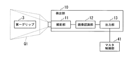
- FIG. 3 is a schematic diagram illustrating the configuration of the detection unit 10.
- the detection unit 10 includes a photographing unit 11, an image recognition unit 12, and an output unit 13.
- the imaging unit 11 includes a first imaging unit that performs imaging from a predetermined direction, and a second imaging unit that performs imaging from a direction different from the predetermined one direction, and is located within the field of view Q1. Two images with different angles can be taken simultaneously with the first grip 3.
- the image acquired by the imaging unit 11 is output to the image recognition unit 12.
- the image recognition unit 12 distinguishes and recognizes the first marker 5 and the second marker 9 from the captured image by a known image recognition process, and acquires the coordinates of the first marker 5 and the second marker 9. Further, the type of the input unit used is discriminated and recognized by identifying the marker or the like.
- the output unit 13 outputs the coordinates of the markers 5 and 9 acquired by the image recognition unit 12 to the master control unit 41 as coordinate information and outputs the recognized type of the input unit.
- the coordinate information output from the output unit 13 specifies information (first information) for specifying the position and orientation of the main body 4 of the first grip 3 and the operation input state of the movable unit 6.
- Information (second information) Regardless of whether or not the first grip 3 is moving within the field of view Q1, the output unit 13 outputs coordinate information according to a predetermined transmission timing.
- the operator holds and operates the first grip 3 within the field of view of the imaging unit 11 of the detection unit 10, whereby the end effector of the treatment tool 50 and the slave arm to which the treatment tool 50 is attached.
- Operation input for operating 14 can be performed. That is, the position and posture of the end effector can be changed by the position and posture of the main body 4, and the open / closed state of the forceps member 51 can be changed by operating the movable portion 6. Note that the position and orientation of the end effector are controlled based on a predetermined coordinate system set in the main body 4.
- the slave manipulator 14 includes a plurality of slave arms 19 to which the endoscope device 15 and the treatment tool 50 are respectively attached, and an actuator (not shown) that operates the treatment tool 50 and the slave arm 19. Prepare.
- Each actuator provided in the slave manipulator 14 operates according to a drive signal output from the slave control unit 42 of the control unit 40.
- the endoscope device 15 provided in one of the slave arms 19 acquires an image of the surgical field including the treatment target and the distal end portion of the treatment tool 50 and outputs the acquired image to the display unit 20.
- the endoscope apparatus 15 is configured to be used without being attached to the slave arm 19 so that the surgical field displayed on the display unit 20 is fixed, or an assistant in the operating room is manually adjusted. Also good.
- the position and orientation of the end effector provided at the distal end portion of the treatment instrument 50 are detected by a position and orientation detection means (not shown) provided on the end effector or the slave arm 19.
- the position and orientation of the end effector detected by the position and orientation detection means can be output to the slave control unit 42 or referred to by the slave control unit 42.
- Examples of the position / orientation detection means include an encoder provided on each joint axis of the slave arm 19. From these joint displacement amounts, the position and orientation can be calculated by solving kinematics.
- the display unit 20 is attached to the same base as the detection unit 10 of the master manipulator 2 and is installed in front of the operator Op.
- the display unit 20 includes a display panel 21 that displays an image acquired by the endoscope device 15.
- a liquid crystal panel, an organic EL panel, or the like can be appropriately selected and employed.
- the display panel may be a 3D panel that displays a stereoscopically visible image.
- a 3D panel for displaying a stereoscopically viewable image various known configurations such as a configuration capable of separating right-eye and left-eye images with dedicated glasses and a configuration capable of autostereoscopic viewing are appropriately selected. Can be adopted.
- the imaging unit 11 of the detection unit 10 causes the first grip 3 and the first marker 5 and the second marker 9 provided on the surface thereof to be captured.
- An image including is acquired.
- the image recognition unit 12 identifies the coordinates of each first marker 5 and each second marker 9 based on the image.
- the specified coordinate information is sent from the output unit 13 to the master control unit 41.
- the master control unit 41 calculates the position and orientation of the main body 4 of the first grip 3 and the operation input to the movable unit 6 based on the received coordinate information, and attaches them to the slave arm 19 and the slave arm 19.
- a predetermined conversion process is performed to correspond to the coordinate system of the treatment instrument 50, the endoscope apparatus 15 and the like (hereinafter simply referred to as “treatment instrument etc.”), and an operation signal of the slave manipulator 14 is generated.
- the generated operation signal is transmitted to the slave control unit 42, sent from the slave control unit 42 to the slave manipulator 19 as a drive signal, and the slave arm 19 and the treatment instrument attached to the slave arm are used as the drive signal. Work on the basis.
- the first grip 3 held by the operator Op is associated with one of the slave arms. Therefore, only the associated slave arm and the treatment instrument attached to the slave arm operate by operation input via the first grip 3.
- the operator Op steps on the foot switch (input cutting unit) 22 shown in FIG. 4 to switch between the master manipulator 2 and the slave manipulator 14.
- the connection is disconnected and the slave manipulator 14 is not operated by the operation input.
- the slave arm to be operated is input to the master manipulator 2 through an interface (not shown) and specified, and the foot switch 22 is stepped on again, the master manipulator 2 and the slave manipulator 14 are connected again, and the slave arm to be operated And an input unit held by the person.
- the slave arm and the treatment instrument 50A currently associated with each other extend from the lower side of the screen of the display panel 21, and the slave arm and the treatment instrument 50B to be operated next are displayed. Is extended from the opposite upper side in the screen, the direction of the end effector of these two treatment tools is opposite. Therefore, in the conventional medical manipulator, when the end effector of the treatment instrument 50B is intuitively operated using the first grip 3, as shown in FIG. 5, the hand of the operator Op holding the first grip 3 is used. Must be in an unnatural posture. That is, in the conventional medical manipulator, since the direction of the first grip 3 is the same as that of the end effector, the operation may be difficult.
- FIG. 6 is a schematic diagram showing the second grip 31.
- the basic structure of the second grip 31 is the same as that of the first grip 3, and has a main body portion 32 and a pair of movable portions 33, but the portion to which the movable portion 33 is rotatably attached is the front end side of the main body portion 32. This is significantly different from the first grip 3. Therefore, when the operator Op holds the second grip 31, the direction of the movable part is opposite to that of the first grip 3.
- the second grip 31 is provided with a first marker 34 and a second marker 35 as in the first grip, but these markers are different from the markers provided in the first grip 3 in shape, color, and the like. Yes. Therefore, the detection unit 10 can determine and recognize which of the first grip 3 and the second grip 31 is the input unit held by the operator Op.
- FIG. 7 is a flowchart showing a flow of operation at the time of the change.
- step S10 the operator Op steps on the foot switch 22 to disconnect the connection between the master manipulator 2 and the slave manipulator 14.
- step S20 the operator Op designates the slave arm to be operated after the change by inputting to the master manipulator 2.
- step S30 the master control unit 41 changes the slave arm associated with the master manipulator 2 to the one specified in step S20.
- step S ⁇ b> 40 it is determined whether the input unit held by the operator Op, that is, the currently used input unit is the first grip 3 or the second grip 31.
- step S40 when the detection unit 10 recognizes that the operator Op holds the same first grip 3 as before cutting, the process proceeds to step S50.
- step S40 when the detection unit 10 recognizes that the operator Op holds the second grip 31 different from that before cutting, the process proceeds to step S41.
- step S41 the master control unit 41 reads out the coordinate system, kinematic calculation method, and the like set in advance for the second grip 31 from storage means (not shown) such as a memory, for example. This is set as a processing condition when the operation signal is generated in the unit 41.
- step S41 ends, the process proceeds to step S50.
- step S50 the master control unit 41 determines whether or not the operator Op has instructed reconnection between the master manipulator 2 and the slave manipulator 14 by a predetermined operation (for example, stepping on the foot switch 22 for a certain time). If the determination is NO, the process returns to step S40. When the result of the determination is YES, the process proceeds to step S60, and the master control unit 41 connects the slave arm 19 associated with the master manipulator 2. After that, the master control unit 41 generates an operation signal to be transmitted to the slave control unit 42 based on the operation input to the master manipulator 2 and the set processing conditions according to the set processing conditions.
- a predetermined operation for example, stepping on the foot switch 22 for a certain time.
- FIG. 8 is a diagram illustrating a difference in processing conditions between the first grip 3 and the second grip 31.
- the second grip 31 can be operated intuitively with the same hand posture as the first grip.
- the position of the origin of the coordinate system Cs2 is set to the front end side of the main body 32.
- the orientation of the coordinates is such that the origin position of the coordinate system set in the input unit and the distal end of the treatment instrument 50 coincide with each other so that the operator Op feels that the operator Op is pinching and moving the distal end of the treatment instrument 50. It is set to be.
- the detection unit 10 recognizes the changed input unit, and the master control unit operates the operation.
- the processing conditions for generating the signal are changed to predetermined contents associated with the recognized input unit. Therefore, the surgeon does not need to change the coordinate system or kinematic calculation method by himself, and can continue intuitive operation even after switching the slave arm by simply changing the input unit to be held.
- the origin of the coordinate system in the second grip 31 may be set as appropriate. For example, as shown in FIG. 9 (b), it may be set at the middle portion in the longitudinal direction of the main body 32, or when the main body 32 is held as shown in FIG. 9 (c), May be set at the end. At this time, assuming that the coordinate system and kinematic conditions on the slave arm 19 side are fixed, even if the operation input to the second grip 31 is the same, FIG. 9 (a) to FIG. 9 (c). As shown, the operations of the slave arm 19 and the end effector vary depending on the setting of the origin of the coordinate system in the second grip 31 that is the input unit. How to set the origin of the coordinate system may be determined in view of the operator's preference and ease of operation. Further, fine adjustment may be possible by an operator inputting to the interface after switching the slave arm.
- FIG. 10 is a flowchart showing an operation flow when changing the slave arm in the modification of the present embodiment.
- step S40 when the input unit held by the operator Op is changed, that is, when the detection unit 10 recognizes that the operator Op is holding the second grip 31, the process proceeds to step S70.
- step S ⁇ b> 70 the master control unit 41 determines whether there is a slave arm that is preferably operated by the second grip 31 based on the positional relationship of the other slave arm with respect to the slave arm that was operated before cutting. To do. If the determination is NO, the process proceeds to step S61, and the master control unit 41 displays a warning message such as “There is no slave arm that can be suitably operated with this grip. 20 is displayed. Thereafter, the process returns to step S40.
- step S40 the process proceeds to step S62.
- step S62 the master control unit 41 highlights the corresponding slave arm or displays it on the display unit 20 in a state where the slave arm can be distinguished from other slave arms. Confirmation message such as “Do you want to operate?” Is displayed and the confirmation input by the operator Op is waited for. When there are a plurality of corresponding slave arms, a message prompting the operator Op to select may be displayed on the display unit 20.
- step S30 When confirmation is input by the surgeon Op, the process proceeds to step S30 and the association of the slave arms is changed. Further, the process proceeds to step S41, and the processing condition is changed. Thereafter, the flow after the process proceeds to step S50 is the same as in the first embodiment.
- the master control unit selects the slave arm to be suitably operated or its candidate based on the type of the input unit recognized by the detection unit. It is also possible to adopt a configuration in which the slave arm can be switched without requiring designation by. In the above modification, for example, when there is only one corresponding slave arm in the determination in step S60, the confirmation message display and the confirmation input by the surgeon are omitted, and the master control unit automatically selects the slave arm. And selection of processing conditions according to the input unit may be performed.
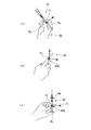
- FIG. 11A to FIG. 11C are views showing a first grip 61, a second grip 62, and a third grip 63, which are input parts in the medical manipulator of the present embodiment, respectively.
- Each grip 61, 62, 63 in this embodiment has a shape resembling a tool having the same function as the end effector of the corresponding treatment tool.
- the first grip 61 is a lever type
- the second grip 62 is a scissor type
- the third grip 63 is a syringe type.
- each end effector of the treatment instrument has a reference position and a coordinate system that can be intuitively operated by a general operator.
- the coordinate position of the reference position may be a position that is familiar to the use of normal surgery or a coordinate position that is easy for an operator peculiar to the shape to recognize. For example, if it is a lever type, as shown in FIG. 11 (a), as shown in FIG. 11 (b), as shown in FIG.
- a rotating shaft 62A serving as the center of relative rotation of the two members having blades and a syringe type as shown in FIG.
- each grip 61, 62, 63 as an input unit has the shape of a tool having the same function as the corresponding end effector, a more intuitive operation is possible.
- the types of input units included in the medical manipulator are not limited to two types, and three or more types may be provided.
- three or more types of input units are provided, at least two of the input units in which predetermined processing conditions associated with the recognized input units are set in the master control unit are within the technical scope of the present invention. Belonging to. In the present embodiment, all of the input units do not have to have a tool shape having the same function as the corresponding end effector. Therefore, it is sufficient that at least one input unit has such a shape.
- FIG. 12 shows the first grip 71 in the medical manipulator of the present embodiment.
- the first grip 71 is in the shape of an elongated bar, and the operator Op holds the first end portion 71A of the first grip 71 for operation.
- the first grip 71 of the operation unit can input 6 degrees of freedom of position / posture, whereas the slave side has only 3 degrees of freedom (yaw, pitch, linear motion). In such a case, there are a plurality of combinations as to how to move the slave side with 3 degrees of freedom with respect to the input value with 6 degrees of freedom of the operation unit.
- the rod-shaped first grip 71 swings in a first plane passing through the axis of the first grip 71 around the held first end 71A among the movements of six degrees of freedom (arrow A1 in FIG. 12). And swinging in the second plane that passes through the first grip 71 and orthogonal to the first plane (arrow A2 in FIG. 12), and advances and retreats in the direction parallel to the axis of the first grip 71 (arrow in FIG. 12).
- the movement in three degrees of freedom with A3) has a structure that is easy for the operator to be intuitively aware of.
- the processing conditions are set so that the master control unit 41 generates an operation signal using only the input values of the three degrees of freedom. Is set. Thereafter, the second end portion 71B of the first grip 71 is used as a reference position, and the tip end 75A of the end effector 75 is operated correspondingly.
- FIG. 13 shows the second grip 72 in the medical manipulator of the present embodiment.
- the second grip 72 is formed in a substantially spherical shape, and the operator Op holds the entire second grip 72 so as to wrap it with a hand. Similar to the first grip 71 described above, there are a plurality of combinations as to how to move the slave side with three degrees of freedom with respect to the input value with six degrees of freedom of the operation unit.
- the grip that is held and wrapped by hand is easy to be intuitively recognized by the operator as to the movement of moving the entire grip to a desired position, such as a mouse of a computer.
- the master control unit 41 uses only the input values of the movement amounts in three axes orthogonal to each other at a predetermined position of the second grip 72, for example, the center of gravity.
- the processing conditions are set so as to generate Thereafter, operation is performed so that the position of the tip 75A of the end effector 75 moves corresponding to the reference position with a predetermined position where the three axes are orthogonal to each other as a reference position.
- the operator can continue intuitive operation only by replacing
- the degree of freedom (master-slave) used to generate the operation signal of the slave arm and the treatment instrument among the command values of 6 degrees of freedom input from the operation unit for example. Since the processing conditions are set such that the conversion calculation formula) is specified as a predetermined one associated in advance, an intuitive operation can be suitably performed.
- the content of the processing conditions set in the operation signal generation unit based on the type of the input unit recognized by the detection unit is not limited to the above.
- the processing conditions include various control parameters such as the motion scale ratio, the type and strength of the filter used for signal generation, the operation speed, and the current limit value of the slave manipulator (the limit value of the operation signal output). Also good. Some specific examples are given below.
- the motion scale ratio set when the corresponding input unit is recognized is set large, and the operation is reduced and transmitted to the slave.
- the motion scale ratio set when the corresponding input unit is recognized is set small, and the operation is expanded and transmitted to the slave.
- the end effector is a needle holder or the like, it is possible to suppress camera shake of the end effector by setting processing conditions so that a predetermined filter is strongly applied to the operation input when the corresponding input unit is recognized. Operation becomes possible.
- the end effector When the end effector is a scissors or the like, the incision can be smoothly performed by setting the operation speed set when the corresponding input unit is recognized faster.
- the end effector When the end effector is a grasping forceps or the like for grasping an organ, the current limit value of a motor or the like that drives the end effector is set larger when the corresponding input unit is recognized. In this way, since a large force is generated by the end effector, the tissue or the like can be suitably grasped.
- FIG. 14A is a diagram showing the grip 81 in such a modification.
- the main body portion 82 is provided with four markers 83A to 83D as first markers.
- the second marker is not shown.
- the marker 83 ⁇ / b> A among the four first markers is covered with the hand of the operator Op and is not detected by the detection unit 10. .
- the detection unit 10 recognizes that the first input unit is held.
- the marker 83D is covered with the hand of the operator Op and is not detected by the detection unit 10 among the four first markers.
- the detection unit 10 recognizes that the second input unit is held.
- two types of states a state in which the detection unit 10 recognizes as the first input unit and a state in which the detection unit 10 recognizes as the second input unit depending on how the grip 81 is held. Therefore, the effects of the present invention can be achieved.
- a common input mechanism is provided for the first input unit and the second input unit, and the processing conditions are set so that the function exerted by the input to the input mechanism varies depending on the type of the input unit recognized by the detection unit. May be.
- each of the plurality of input units includes a button
- the following function switching is possible.
- the end effector is a needle holder
- the state in which the jaw is closed by the operation input to the button is maintained, and the sustained holding of the curved needle or the like is possible.
- the end effector is a high-frequency treatment instrument, energization to the treatment section can be turned on / off by an operation input to the button.
- the end effector is a stitching device such as a stapler or a clip
- stitching can be performed by an operation input to the button.
- the end effector is an endoscope
- zooming or acquire a still image by an operation input to a button. Since the above is merely an example, it is natural that various functions can be assigned to various end effectors.
- the common input mechanism is not limited to a button, and may be an analog type knob such as a slide type or a rotary type, or the above-described movable part.
- an input unit for a treatment instrument whose end effector is not a forceps may include the movable unit 6, and the processing conditions may be set so that a function that does not open or close the forceps is exhibited by an input to the movable unit 6.
- the input unit may be configured to be physically attachable to and detachable from the operation unit.
- the input unit held by the surgeon does not necessarily have to be determined by image processing or the like.
- the input unit has an identification unit such as a pin that has information such as a type and is inserted into the operation unit at the time of attachment / detachment, and when the input unit is mounted, the detection unit receives information such as the type of the input unit from the identification unit It is good also as a structure which acquires.
- the medical manipulator of the present invention is not limited to one in which the operation unit is remotely operated. Therefore, even in a medical manipulator in which the operation unit and the operation unit are physically connected, the above-described effects can be obtained by applying the present invention without any problem. Furthermore, the medical manipulator of the present invention may be configured such that a plurality of input units are operated simultaneously, and a plurality of operation units corresponding to the respective input units operate simultaneously.
- the present invention can be widely applied to medical manipulators that operate an operation unit by an operation input via an input unit.
Abstract
本発明の医療用マニピュレータ(1)は、交換可能な第一入力部および第二入力部を有するマスタマニピュレータ(2)と、マスタマニピュレータ(2)に対する入力を所定の処理条件にもとづいて処理して操作信号を生成するマスタ制御部(41)と、操作信号により動作するスレーブマニピュレータ(14)と、使用されている入力部の種類を認識する検出部(10)とを備え、第一入力部に対応付けられた処理条件と、第二入力部に対応付けられた処理条件とが異なっており、マスタ制御部(41)は、検出部で認識された入力部に対応付けられた処理条件にもとづいて操作信号を生成する。
Description
本発明は、医療用マニピュレータ、より詳しくは、術者が把持する入力部に応じてエンドエフェクタの制御を切り替える医療用マニピュレータ、および医療用マニピュレータの制御方法に関する。
本願は、2011年8月4日に米国に出願された仮出願61/515,203に基づき優先権を主張し、その内容をここに援用する。
本願は、2011年8月4日に米国に出願された仮出願61/515,203に基づき優先権を主張し、その内容をここに援用する。
従来、患者の体内で処置を行う処置具(エンドエフェクタ)を、操作部を介して操作する医療用のマニピュレータが知られている。
エンドエフェクタは、対象とする処置により、持針器型、鉗子型、剪刀型、メス型、高周波処置具等の様々な形状を有する複数種類が準備され、通常手術等の各工程において、これら複数のエンドエフェクタが適宜交換または組み合わせて用いられる。
エンドエフェクタは、対象とする処置により、持針器型、鉗子型、剪刀型、メス型、高周波処置具等の様々な形状を有する複数種類が準備され、通常手術等の各工程において、これら複数のエンドエフェクタが適宜交換または組み合わせて用いられる。
エンドエフェクタが変わると、それに伴って操作部における操作内容も変化するため、単一の操作部ではある種類のエンドエフェクタの操作が困難となることがある。この問題を解決するために、特許文献1では、複数種類のエンドエフェクタのそれぞれに対応した複数のグリップ(入力部)を備え、これを交換可能に操作ユニットに取り付けることが提案されている。これにより、術者は、各エンドエフェクタに最も適したグリップを用いてエンドエフェクタの操作を行うことができる。
しかしながら、特許文献1に記載の発明では、グリップの交換時に、グリップを介した操作入力に対する処理を変更することは充分考慮されていない。したがって、グリップの形状や状態、さらには対応するエンドエフェクタの形状や状態と、これらの組合せに適した処理が行われない結果、用いるグリップの種類によっては、術者が直感的に操作することが困難となる場合があるという問題が残されている。
上記事項を踏まえ、本発明は、複数の入力部を備えつつ、各入力部により直感的にエンドエフェクタを操作することができる医療用マニピュレータを提供することを目的とする。
本発明の他の目的は、術者が保持した入力部の種類によらず、常にエンドエフェクタの直感的な操作を可能とする医療用マニピュレータの制御方法を提供することである。
上記事項を踏まえ、本発明は、複数の入力部を備えつつ、各入力部により直感的にエンドエフェクタを操作することができる医療用マニピュレータを提供することを目的とする。
本発明の他の目的は、術者が保持した入力部の種類によらず、常にエンドエフェクタの直感的な操作を可能とする医療用マニピュレータの制御方法を提供することである。
本発明の第一の態様は、交換可能な第一入力部および第二入力部を有する操作部と、前記操作部に対する入力を所定の処理条件にもとづいて処理して操作信号を生成する信号生成部と、前記操作信号により動作する動作部と、使用されている入力部の種類を認識する検出部とを備え、前記第一入力部に対応付けられた前記処理条件と、前記第二入力部に対応付けられた前記処理条件とが異なっており、前記信号生成部は、前記検出部で認識された入力部に対応付けられた処理条件にもとづいて前記操作信号を生成する医療用マニピュレータである。
前記処理条件は、前記入力部における座標系の設定態様を含んでもよいし、前記入力部における座標系の原点位置を含んでもよい。
さらに、前記処理条件は、前記入力に含まれる自由度のうち、前記操作信号の生成に用いられる自由度を特定する情報を含んでもよい。
さらに、前記処理条件は、前記入力に含まれる自由度のうち、前記操作信号の生成に用いられる自由度を特定する情報を含んでもよい。
前記動作部は、所定の機能を発揮するエンドエフェクタを有し、前記第一入力部および前記第二入力部の少なくとも一方が、前記機能を発揮する道具と同等の形状を有してもよい。
このとき、前記処理条件は、前記入力部への入力と前記操作信号とのスケール比を含んでもよいし、前記操作信号の生成時に用いるフィルタについての情報を含んでもよい。また、前記操作信号の出力の限界値を含んでもよい。
このとき、前記処理条件は、前記入力部への入力と前記操作信号とのスケール比を含んでもよいし、前記操作信号の生成時に用いるフィルタについての情報を含んでもよい。また、前記操作信号の出力の限界値を含んでもよい。
前記第一入力部と前記第二入力部とは共通する入力機構を有し、前記処理条件は、前記入力機構への入力により前記動作部において発揮される機能の種類を含んでもよい。
本発明の第二の態様は、交換可能な第一入力部および第二入力部を有する操作部と、前記操作部に対する入力を所定の処理条件にもとづいて処理して操作信号を生成する信号生成部と、前記操作信号により動作する動作部と、使用されている入力部の種類を認識する検出部と、を備えた医療用マニピュレータの制御方法であって、前記第一入力部および前記第二入力部にそれぞれ異なる前記処理条件を対応付けるステップと、前記検出部により使用されている入力部の種類を認識するステップと、認識された入力部に対応付けられた前記処理条件を前記信号生成部に設定するステップとを備える。
本発明の医療用マニピュレータによれば、複数の入力部を備えつつ、各入力部により直感的にエンドエフェクタを操作することができる。
また、本発明の医療用マニピュレータの制御方法によれば、術者が保持した入力部の種類によらず、常にエンドエフェクタの直感的な操作が可能となる。
また、本発明の医療用マニピュレータの制御方法によれば、術者が保持した入力部の種類によらず、常にエンドエフェクタの直感的な操作が可能となる。
本発明の第一実施形態の医療用マニピュレータ及びその制御方法について、図1から図10を参照して説明する。
図1は、本実施形態の医療用マニピュレータ1の全体構成を示す概略図である。図1に示すように、本実施形態の医療用マニピュレータ1は、マスタマニピュレータ(操作部)2と、スレーブマニピュレータ(動作部)14とを備えている。すなわち、医療用マニピュレータ1は、術者(操作者)Opによるマスタマニピュレータ2の操作に追従させるようにしてスレーブマニピュレータ14およびスレーブマニピュレータ14に取り付けられた処置具(後述)を遠隔制御するマスタスレーブマニピュレータである。
マスタマニピュレータ2を介した操作指令は、制御部40のマスタ制御部(操作信号生成部)41に送信され、所定の処理条件にもとづいて変換処理(後述)が施されることにより操作信号が生成される。生成された操作信号はスレーブ制御部42に送られる。その後、スレーブ制御部42からスレーブマニピュレータ14へ操作信号にもとづいた駆動信号が送られ、スレーブマニピュレータ14および処置具が動作する。
マスタマニピュレータ2を介した操作指令は、制御部40のマスタ制御部(操作信号生成部)41に送信され、所定の処理条件にもとづいて変換処理(後述)が施されることにより操作信号が生成される。生成された操作信号はスレーブ制御部42に送られる。その後、スレーブ制御部42からスレーブマニピュレータ14へ操作信号にもとづいた駆動信号が送られ、スレーブマニピュレータ14および処置具が動作する。
マスタマニピュレータ2は、術者Opによって保持される第一グリップ(第一入力部)3と、第一グリップ3を検出する検出部10と、術野を表示する表示部20とを備えている。なお、医療用マニピュレータ1は、術者Opが保持するグリップを複数備えているが、詳細については後述する。
第一グリップ3は、図2に示すように、本体部4と、本体部4に対して移動可能に連結された一対の可動部6とを備えている。
本体部4の外面には、互いに離間する3箇所に第一マーカー5が設けられている。3つの第一マーカー5は、第一マーカー5を頂点とする三角形の三辺の長さが互いに異なるように配置されている。これにより、検出部10が取得した画像において各第一マーカー5の相対位置関係を特定することで本体部4の姿勢を算出することができる。
本体部4の外面には、互いに離間する3箇所に第一マーカー5が設けられている。3つの第一マーカー5は、第一マーカー5を頂点とする三角形の三辺の長さが互いに異なるように配置されている。これにより、検出部10が取得した画像において各第一マーカー5の相対位置関係を特定することで本体部4の姿勢を算出することができる。
一対の可動部6は、それぞれ第一の端部6Aが本体部4に対して回動可能に支持されている。可動部6は、リンク7および付勢部材8を介しても本体部4に支持されており、第二の端部6Bは、術者Opが力を加えない状態において本体部4から離間するように付勢されている。各可動部6の第二の端部6Bには、第二マーカー9が設けられている。
図2下部には、スレーブマニピュレータ14に取り付けられる処置具50の先端部を模式的に示している。処置具50の先端には、エンドエフェクタとして、開閉する一対の鉗子部材51が設けられている。術者Opは、可動部6の第二の端部6Bを本体部4に接近および離間させるように操作することで、鉗子部材51を開閉させるための操作入力を行うことができる。
図3は、検出部10の構成を示す模式図である。検出部10は、撮影部11と、画像認識部12と、出力部13とを備えている。
撮影部11は、所定の一方向から撮影をする第一の撮像部と、上記所定の一方向とは別の方向から撮影をする第二の撮像部とを備えており、視野Q1内に位置する第一グリップ3に対して、アングルが異なる2画像を同時に撮影することができる。撮影部11の取得した画像は、画像認識部12へ出力される。
撮影部11は、所定の一方向から撮影をする第一の撮像部と、上記所定の一方向とは別の方向から撮影をする第二の撮像部とを備えており、視野Q1内に位置する第一グリップ3に対して、アングルが異なる2画像を同時に撮影することができる。撮影部11の取得した画像は、画像認識部12へ出力される。
画像認識部12は、撮影された画像から、公知の画像認識処理により第一マーカー5及び第二マーカー9を区別して認識し、第一マーカー5及び第二マーカー9の座標を取得する。さらに、マーカーを識別する等により、使用されている入力部の種類を判別し、認識する。
出力部13は、画像認識部12において取得された各マーカー5、9の座標を、マスタ制御部41へと座標情報として出力するとともに、認識された入力部の種類を出力する。本実施形態において出力部13から出力される座標情報は、第一グリップ3の本体部4の位置及び姿勢を特定するための情報(第一情報)、及び可動部6の操作入力状態を特定するための情報(第二情報)とを含んでいる。出力部13からは、第一グリップ3が視野Q1内で移動しているか否かに関わらず、所定の発信タイミングに従って座標情報が出力される。
出力部13は、画像認識部12において取得された各マーカー5、9の座標を、マスタ制御部41へと座標情報として出力するとともに、認識された入力部の種類を出力する。本実施形態において出力部13から出力される座標情報は、第一グリップ3の本体部4の位置及び姿勢を特定するための情報(第一情報)、及び可動部6の操作入力状態を特定するための情報(第二情報)とを含んでいる。出力部13からは、第一グリップ3が視野Q1内で移動しているか否かに関わらず、所定の発信タイミングに従って座標情報が出力される。
以上の構成により、術者Opが検出部10の撮影部11の視野内で第一グリップ3を保持して操作することにより、処置具50のエンドエフェクタ、および処置具50が取り付けられたスレーブアーム14を操作するための操作入力を行うことができる。すなわち、本体部4の位置および姿勢によりエンドエフェクタの位置及び姿勢を、可動部6の操作により鉗子部材51の開閉状態を、それぞれ変化させることができる。なお、エンドエフェクタの位置及び姿勢は、本体部4に設定された所定の座標系に基づいて制御される。
図1に示すように、スレーブマニピュレータ14は、内視鏡装置15及び処置具50がそれぞれ取り付けられた複数のスレーブアーム19と、処置具50及びスレーブアーム19を動作させるアクチュエータ(不図示)とを備える。スレーブマニピュレータ14に設けられた各アクチュエータは、制御部40のスレーブ制御部42から出力される駆動信号に従って動作する。スレーブアーム19の一つに設けられた内視鏡装置15は、処置対象物や処置具50先端部が含まれる術野の画像を取得して表示部20へと出力する。
なお、内視鏡装置15は、スレーブアーム19に取り付けずに使用することで、表示部20に表示される術野を固定したり、手術室内の補助者等が手動により調節したりする構成としてもよい。
なお、内視鏡装置15は、スレーブアーム19に取り付けずに使用することで、表示部20に表示される術野を固定したり、手術室内の補助者等が手動により調節したりする構成としてもよい。
処置具50先端部に設けられたエンドエフェクタの位置及び姿勢は、エンドエフェクタ若しくはスレーブアーム19に設けられた不図示の位置姿勢検出手段によって検出される。当該位置姿勢検出手段によって検出されたエンドエフェクタの位置及び姿勢は、スレーブ制御部42へ出力されたり、スレーブ制御部42によって参照されたりすることも可能である。
位置姿勢検出手段としては、たとえば、スレーブアーム19の各関節軸に設けられたエンコーダなどが挙げられる。これらの関節変位量から、運動学を解くことで該位置姿勢を算出することができる。
位置姿勢検出手段としては、たとえば、スレーブアーム19の各関節軸に設けられたエンコーダなどが挙げられる。これらの関節変位量から、運動学を解くことで該位置姿勢を算出することができる。
図1に示すように、表示部20は、マスタマニピュレータ2の検出部10と同じ土台に取り付けられており、術者Opの前方に設置されている。表示部20は、内視鏡装置15によって取得された画像を表示する表示パネル21を有している。表示パネル21としては、液晶パネルや有機ELパネル等を適宜選択して採用することができる。また、表示パネルは、立体視可能な画像を表示する3Dパネルであってもよい。立体視可能な画像を表示する3Dパネルとしては、専用のメガネにより右目用と左目用の画像が分離可能な構成や、裸眼立体視が可能な構成等の各種の公知の構成を適宜選択して採用することができる。
上記のように構成された、本実施形態の医療用マニピュレータ1の使用時の動作について説明する。
術者Opが第一グリップ3を検出部10の視野Q1内で保持すると、検出部10の撮影部11により、第一グリップ3、およびその表面に設けられた第一マーカー5および第二マーカー9を含む画像が取得される。画像認識部12は、当該画像に基づいて、各第一マーカー5および各第二マーカー9の座標を特定する。
特定された座標情報は、出力部13からマスタ制御部41に送られる。
術者Opが第一グリップ3を検出部10の視野Q1内で保持すると、検出部10の撮影部11により、第一グリップ3、およびその表面に設けられた第一マーカー5および第二マーカー9を含む画像が取得される。画像認識部12は、当該画像に基づいて、各第一マーカー5および各第二マーカー9の座標を特定する。
特定された座標情報は、出力部13からマスタ制御部41に送られる。
マスタ制御部41では、受信した座標情報に基づいて第一グリップ3の本体部4の位置及び姿勢と、可動部6に対する操作入力を算出し、これらをスレーブアーム19、および当該スレーブアーム19に取り付けられた処置具50や内視鏡装置15等(以下、単に「処置具等」と称する。)の座標系に対応させるための所定の変換処理を行いスレーブマニピュレータ14の操作信号を生成する。生成された操作信号は、スレーブ制御部42に送信され、スレーブ制御部42から駆動信号としてスレーブマニピュレータ19に送られて、スレーブアーム19および当該スレーブアームに取り付けられた処置具等が当該駆動信号に基づいて動作する。
スレーブアーム19が複数用いられる場合、術者Opが保持する第一グリップ3は、そのうちの一つのスレーブアームと対応付けられている。したがって、第一グリップ3を介した操作入力により、対応付けられたスレーブアームおよび当該スレーブアームに取り付けられた処置具等のみが動作する。
スレーブアーム19が複数用いられる場合、術者Opが保持する第一グリップ3は、そのうちの一つのスレーブアームと対応付けられている。したがって、第一グリップ3を介した操作入力により、対応付けられたスレーブアームおよび当該スレーブアームに取り付けられた処置具等のみが動作する。
現在対応付けられているものと異なるスレーブアームをマスタマニピュレータ2で操作したいときは、術者Opは図4に示すフットスイッチ(入力切断部)22を踏んで、マスタマニピュレータ2とスレーブマニピュレータ14との接続を切断して、操作入力によりスレーブマニピュレータ14が動作しない状態にする。その後、操作したいスレーブアームを図示しないインターフェースからマスタマニピュレータ2に入力して指定してからフットスイッチ22を再度踏むと、マスタマニピュレータ2とスレーブマニピュレータ14とが再度接続されて、操作したいスレーブアームと術者が保持する入力部とが関連付けられる。
ここで、例えば図4の表示パネル21に示すように、現在対応付けられているスレーブアームおよび処置具50Aが表示パネル21の画面の下方から延びており、次に操作したいスレーブアームおよび処置具50Bが当該画面において反対側の上方から延びている場合、これら2つの処置具のエンドエフェクタの向きは反対となっている。そのため、従来の医療用マニピュレータにおいて、処置具50Bのエンドエフェクタを第一グリップ3を用いて直感的に操作しようとすると、図5に示すように、第一グリップ3を保持する術者Opの手を不自然な姿勢にしなければならない。すなわち、従来の医療用マニピュレータでは、第一グリップ3の向きを当該エンドエフェクタと同一にするために、操作が困難となる場合がある。
これを防ぐために、術者Opは、保持する入力部を、第一グリップ3から、図6に示す第二グリップ(第二入力部)31に持ち替える。第二グリップ31は表示部の画面の上方から延びるスレーブアームの操作用の入力部である。
図6は、第二グリップ31を示す模式図である。第二グリップ31の基本構造は、第一グリップ3と同様であり、本体部32および一対の可動部33を有するが、可動部33が回動可能に取り付けられる部位が、本体部32の先端側である点が第一グリップ3と大きく異なっている。したがって、術者Opが第二グリップ31を保持すると、可動部の向きが第一グリップ3と逆になる。
また、第二グリップ31は、第一グリップ同様、第一マーカー34および第二マーカー35を備えているが、これらマーカーは、形状や色彩等が第一グリップ3に設けられたマーカーとは異なっている。したがって、検出部10は、術者Opが保持している入力部が第一グリップ3および第二グリップ31のいずれであるかを判別して認識することができる。
医療用マニピュレータ1における、第一グリップ3から第二グリップ31への持ち替えを伴うスレーブアームの変更時の動作について説明する。図7は、当該変更時の動作の流れを示すフローチャートである。
まずステップS10において、術者Opはフットスイッチ22を踏んでマスタマニピュレータ2とスレーブマニピュレータ14との接続を切断する。
次にステップS20において、術者Opは変更後に操作するスレーブアームをマスタマニピュレータ2への入力により指定する。
ステップS30において、マスタ制御部41は、マスタマニピュレータ2と対応付けられるスレーブアームをステップS20で指定されたものに変更する。
ステップS40において、術者Opが保持している、すなわち現在使用されている入力部が、第一グリップ3および第二グリップ31のいずれであるかを判別する。ステップS40において、術者Opが切断前と同一の第一グリップ3を保持していると検出部10が認識したときは、処理はステップS50に進む。
ステップS40において、術者Opが切断前と異なる第二グリップ31を保持していると検出部10が認識したときは、処理はステップS41に進む。ステップS41において、マスタ制御部41は、第二グリップ31に対してあらかじめ設定された座標系および運動学計算方法等を、例えばメモリ等の記憶手段(不図示)から読み出す等により、以後のマスタ制御部41における操作信号生成時の処理条件として設定する。ステップS41が終了したら、処理はステップS50に進む。
ステップS40において、術者Opが切断前と異なる第二グリップ31を保持していると検出部10が認識したときは、処理はステップS41に進む。ステップS41において、マスタ制御部41は、第二グリップ31に対してあらかじめ設定された座標系および運動学計算方法等を、例えばメモリ等の記憶手段(不図示)から読み出す等により、以後のマスタ制御部41における操作信号生成時の処理条件として設定する。ステップS41が終了したら、処理はステップS50に進む。
ステップS50では、術者Opが所定の操作(例えばフットスイッチ22を一定時間踏む等)により、マスタマニピュレータ2とスレーブマニピュレータ14との再接続を指示したか否かをマスタ制御部41が判定する。当該判定がNOの場合は、処理はステップS40に戻る。
当該判定の結果がYESの場合、処理はステップS60に進み、マスタ制御部41は、マスタマニピュレータ2と対応付けられたスレーブアーム19とを接続する。その後は、設定された処理条件により、マスタマニピュレータ2への操作入力および設定された処理条件にもとづいて、マスタ制御部41がスレーブ制御部42に送信される操作信号を生成する。
当該判定の結果がYESの場合、処理はステップS60に進み、マスタ制御部41は、マスタマニピュレータ2と対応付けられたスレーブアーム19とを接続する。その後は、設定された処理条件により、マスタマニピュレータ2への操作入力および設定された処理条件にもとづいて、マスタ制御部41がスレーブ制御部42に送信される操作信号を生成する。
図8は、第一グリップ3と第二グリップ31との処理条件の違いを示す図である。図8(a)に示す第一グリップ3の座標系Cs1に対し、第二グリップ31では、第一グリップを操作するのと同様の手の姿勢で直感的に操作できるように、図8(b)に示すように座標系Cs2の原点の位置を本体部32の先端側に設定されている。さらに、座標の向きは、術者Opが処置具50の先端をつまんで動かしていると感じられるように、入力部に設定された座標系の原点位置と処置具50の先端との姿勢が一致するように設定されている。
本実施形態の医療用マニピュレータ1によれば、操作するスレーブアームの切り替え時に、術者Opが保持する入力部を変更すると、検出部10が変更後の入力部を認識し、マスタ制御部が操作信号を生成する際の処理条件が認識された入力部に対応付けられた所定の内容に変更される。したがって、術者は、自ら座標系や運動学計算方法の変更をする必要がなく、保持する入力部を変更するだけで、スレーブアームの切り替え後も直感的な操作を継続することができる。
本実施形態において、第二グリップ31における座標系の原点は、適宜設定されてよい。例えば、図9(b)に示すように、本体部32の長手方向中間部に設定してもよいし、図9(c)に示すように、本体部32を保持した際に基端側となる端部に設定されてもよい。このとき、スレーブアーム19側における座標系および運動学の条件は固定されていると仮定すると、第二グリップ31に対する操作入力が同一であっても、図9(a)から図9(c)に示すように、スレーブアーム19およびエンドエフェクタの動作が、入力部である第二グリップ31における座標系の原点の設定によって変化する。座標系の原点をどのように設定するかは、術者の嗜好や操作のしやすさ等に鑑みて決定されてよい。また、スレーブアームの切り替え後に術者がインターフェースに入力する等により微調整可能としてもよい。
また、本実施形態では、術者が切り替え後に操作するスレーブアームを指定する例を説明したが、この指定を必要としない構成としてもよい。以下にそのような変形例を示す。
図10は、本実施形態の変形例におけるスレーブアームの変更時の動作の流れを示すフローチャートである。
ステップS10においてマスタ入力部とスレーブマニピュレータとを切断した後、例えば術者が、上述の例と同様に対応付けられるスレーブアームを変更する場合、術者は特にスレーブアームを指定せずに当該スレーブアームの操作に適した第二グリップ31を保持する。
処理はステップS10からステップS20およびS30を経ずにステップS40に進み、術者Opが保持している入力部の種類が判別される。
ステップS10においてマスタ入力部とスレーブマニピュレータとを切断した後、例えば術者が、上述の例と同様に対応付けられるスレーブアームを変更する場合、術者は特にスレーブアームを指定せずに当該スレーブアームの操作に適した第二グリップ31を保持する。
処理はステップS10からステップS20およびS30を経ずにステップS40に進み、術者Opが保持している入力部の種類が判別される。
ステップS40において、術者Op保持する入力部が変更された、すなわち、術者Opが第二グリップ31を保持していると検出部10が認識すると、処理は、ステップS70に進む。ステップS70において、マスタ制御部41は、切断前に操作されていたスレーブアームに対する他のスレーブアームの位置関係等にもとづき、第二グリップ31で好適に操作されるスレーブアームがあるか否かを判定する。当該判定がNOの場合、処理はステップS61に進み、マスタ制御部41は、「このグリップで好適に操作できるスレーブアームがありませんので、第一グリップに持ち替えて下さい。」等の警告メッセージを表示部20に表示する。その後、処理はステップS40に戻る。
ステップS40における判定がYESの場合、処理はステップS62に進む。ステップS62において、マスタ制御部41は、該当するスレーブアームをハイライト表示したり、カーソルで示したりして他のスレーブアームと識別可能な状態で表示部20に表示するとともに、「このスレーブアームを操作しますか?」等の確認メッセージを表示して、術者Opによる確認の入力を待つ。該当するスレーブアームが複数存在する場合は、術者Opに選択を促すメッセージを表示部20に表示させてもよい。
術者Opにより確認の入力がされると、処理はステップS30に進んでスレーブアームの対応付けが変更される。さらに、処理はステップS41に進み、処理条件の変更が行われる。その後、処理がステップS50に進んだ後の流れは、第一実施形態と同様である。
このように、本実施形態の医療用マニピュレータは、検出部が認識した入力部の種類にもとづいて、マスタ制御部が、好適に操作されるスレーブアームまたはその候補を選択することにより、術者Opによる指定を必要とせずにスレーブアームの切り替えを行える構成としてもよい。
なお、上記変形例においては、例えばステップS60における判定で該当するスレーブアームが一つしかなかった場合に、確認メッセージの表示および術者による確認の入力を省略し、マスタ制御部が自動でスレーブアームの選択と、入力部に応じた処理条件の設定とを行うようにしてもよい。
なお、上記変形例においては、例えばステップS60における判定で該当するスレーブアームが一つしかなかった場合に、確認メッセージの表示および術者による確認の入力を省略し、マスタ制御部が自動でスレーブアームの選択と、入力部に応じた処理条件の設定とを行うようにしてもよい。
次に、本発明の第二実施形態について説明する。本実施形態の医療用マニピュレータと第一実施形態の医療用マニピュレータとの異なるところは、入力部の形状である。なお、以降の説明において、すでに説明したものと重複する構成については、同一の符号を付して重複する説明を省略する。
図11(a)から図11(c)は、それぞれ本実施形態の医療用マニピュレータにおける入力部である第一グリップ61、第二グリップ62、および第三グリップ63を示す図である。本実施形態における各グリップ61、62、63は、対応する処置具のエンドエフェクタと同等の機能を有する道具に似せた形状とされている。具体的には、第一グリップ61は鑷子型、第二グリップ62は剪刀型、第三グリップ63は注射器型とされている。
処置具のエンドエフェクタが変わると、操作する際の基準位置をどの位置にすると好適に操作できるかも変化する。すなわち、各エンドエフェクタには、それぞれ一般的な術者が直感的に操作できる基準位置および座標系が存在する。基準位置の座標位置は、普段の手術の使用で使い慣れた位置であったり、形状に特有の操作者が意識しやすい座標位置であったりする。例えば、鑷子型であれば、図11(a)に示すように、保持した術者Opの親指Thと人差し指F1とが当たる部位、剪刀型であれば、図11(b)に示すように、刃を有する2つの部材の相対回転の中心となる回動軸62A、注射器型であれば、図11(c)に示すように、術者Opの人差し指F1および中指F2が掛けられるシリンダ64の基端部64Aに、それぞれ基準位置を設定した座標系を用いることで、直感的な操作が行いやすくなる。
本実施形態では、これを踏まえ、各グリップ61、62、63において、対応するエンドエフェクタに適した部位を基準位置Psとして座標系が設定されており、検出部10が認識したグリップの種類に応じて、設定された座標系および基準位置が、マスタ制御部における処理条件として設定される。
本実施形態では、これを踏まえ、各グリップ61、62、63において、対応するエンドエフェクタに適した部位を基準位置Psとして座標系が設定されており、検出部10が認識したグリップの種類に応じて、設定された座標系および基準位置が、マスタ制御部における処理条件として設定される。
本実施形態の医療用マニピュレータによっても、第一実施形態同様、術者は入力部を交換するだけで直感的な操作を継続することができる。
また、入力部である各グリップ61、62、63が、対応するエンドエフェクタと同等の機能を備える道具の形状とされているため、より直感的な操作が可能になる。
また、入力部である各グリップ61、62、63が、対応するエンドエフェクタと同等の機能を備える道具の形状とされているため、より直感的な操作が可能になる。
本実施形態で示したように、医療用マニピュレータが備える入力部の種類は2種類に限られず、3種類以上備えられてもよい。3種類以上の入力部を備える場合、その中の少なくとも2つの入力部において、認識された入力部と対応付けられた所定の処理条件がマスタ制御部に設定されるものは本発明の技術的範囲に属する。
また、本実施形態においては、入力部のすべてが対応するエンドエフェクタと同等の機能を備える道具の形状とされていなくてもよい。したがって、少なくとも一つの入力部がそのような形状であればよい。
また、本実施形態においては、入力部のすべてが対応するエンドエフェクタと同等の機能を備える道具の形状とされていなくてもよい。したがって、少なくとも一つの入力部がそのような形状であればよい。
次に本発明の第三実施形態について、図12および図13を参照して説明する。本実施形態の医療用マニピュレータと上述の各実施形態との異なるところは、入力部ごとに設定される処理条件において、自由度が変化する点である。
図12は、本実施形態の医療用マニピュレータにおける第一グリップ71を示している。第一グリップ71は、細長い棒状であり、術者Opは第一グリップ71の第一の端部71Aを保持して操作を行う。本実施形態において、操作部の第一グリップ71は位置・姿勢の6自由度の入力ができるのに対して、スレーブ側は3自由度(ヨー、ピッチ、直動)しか有していない。このような場合に、操作部の6自由度の入力値に対して、3自由度のスレーブ側をどのように動かすかについては、複数の組合せが存在する。
棒状の第一グリップ71は、6自由度の動きの中でも、保持した第一の端部71Aを中心として第一グリップ71の軸線を通る第一の面内における揺動(図12における矢印A1)と、第一グリップ71を通り第一の面と直交する第二の面内における揺動(図12における矢印A2)と、第一グリップ71の軸線と平行な方向への進退(図12における矢印A3)との3つの自由度における動きが、術者にとって直感的に意識しやすい構造となっている。本実施形態の医療用マニピュレータでは、検出部10が第一グリップ71を認識したときは、この3自由度の入力値のみを利用してマスタ制御部41が操作信号を生成するように処理条件が設定される。その後は、第一グリップ71の第二の端部71Bを基準位置として、エンドエフェクタ75の先端75Aが対応して動くように操作される。
棒状の第一グリップ71は、6自由度の動きの中でも、保持した第一の端部71Aを中心として第一グリップ71の軸線を通る第一の面内における揺動(図12における矢印A1)と、第一グリップ71を通り第一の面と直交する第二の面内における揺動(図12における矢印A2)と、第一グリップ71の軸線と平行な方向への進退(図12における矢印A3)との3つの自由度における動きが、術者にとって直感的に意識しやすい構造となっている。本実施形態の医療用マニピュレータでは、検出部10が第一グリップ71を認識したときは、この3自由度の入力値のみを利用してマスタ制御部41が操作信号を生成するように処理条件が設定される。その後は、第一グリップ71の第二の端部71Bを基準位置として、エンドエフェクタ75の先端75Aが対応して動くように操作される。
図13は、本実施形態の医療用マニピュレータにおける第二グリップ72を示している。第二グリップ72は、略球状に形成されており、術者Opは、手で包むようにして第二グリップ72全体を保持する。上述の第一グリップ71と同様に、操作部の6自由度の入力値に対して、3自由度のスレーブ側をどのように動かすかについては、複数の組合せが存在する。
ここで、手で包むようにして保持されるグリップは、例えばコンピュータのマウスのように、グリップ全体を所望の位置に移動させるような動きが術者にとって直感的に意識しやすい。そこで、検出部10が第二グリップ72を認識したときは、第二グリップ72の所定位置、例えば重心において互いに直交する3軸における移動量の入力値のみを利用してマスタ制御部41が操作信号を生成するように処理条件が設定される。その後は、上記3軸が互いに直交する所定位置を基準位置として、エンドエフェクタ75の先端75Aの位置が基準位置と対応して動くように操作される。
ここで、手で包むようにして保持されるグリップは、例えばコンピュータのマウスのように、グリップ全体を所望の位置に移動させるような動きが術者にとって直感的に意識しやすい。そこで、検出部10が第二グリップ72を認識したときは、第二グリップ72の所定位置、例えば重心において互いに直交する3軸における移動量の入力値のみを利用してマスタ制御部41が操作信号を生成するように処理条件が設定される。その後は、上記3軸が互いに直交する所定位置を基準位置として、エンドエフェクタ75の先端75Aの位置が基準位置と対応して動くように操作される。
本実施形態の医療用マニピュレータによっても、上述の各実施形態同様、術者は入力部を交換するだけで直感的な操作を継続することができる。
また、術者が保持した入力部に応じて、操作部から入力される、例えば6自由度の指令値のうち、スレーブアーム及び処置具の操作信号を生成するために用いられる自由度(マスタスレーブの変換計算式)が、あらかじめ対応付けられた所定のものに特定されるように処理条件が設定されるため、直感的な操作を好適に行うことができる。
また、術者が保持した入力部に応じて、操作部から入力される、例えば6自由度の指令値のうち、スレーブアーム及び処置具の操作信号を生成するために用いられる自由度(マスタスレーブの変換計算式)が、あらかじめ対応付けられた所定のものに特定されるように処理条件が設定されるため、直感的な操作を好適に行うことができる。
以上、本発明の各実施形態について説明したが、本発明の技術的範囲は上記各実施形態に限定されるものではなく、本発明の趣旨を逸脱しない範囲において構成要素の組み合わせを変えたり、各構成要素に種々の変更を加えたり、削除したりすることが可能である。
まず、本発明において、検出部が認識した入力部の種類に基づいて操作信号生成部に設定される処理条件の内容は上述に限られない。
例えば、処理条件には、モーションスケール比、信号生成時に用いるフィルタの種類や強さ、動作速度、スレーブマニピュレータの電流リミット値(操作信号の出力の限界値)等の各種の制御パラメータが含まれてもよい。以下に具体例をいくつか挙げる。
例えば、処理条件には、モーションスケール比、信号生成時に用いるフィルタの種類や強さ、動作速度、スレーブマニピュレータの電流リミット値(操作信号の出力の限界値)等の各種の制御パラメータが含まれてもよい。以下に具体例をいくつか挙げる。
エンドエフェクタが細かい操作を多く行う持針器等の場合は、対応する入力部が認識されたときに設定されるモーションスケール比を大きく設定し、操作を縮小してスレーブに伝える。一方、エンドエフェクタが大きな操作を多く行う組織牽引器等の場合は、対応する入力部が認識されたときに設定されるモーションスケール比を小さく設定し、操作を拡大してスレーブに伝える。これにより、直感的かつ容易な操作が可能となる。
エンドエフェクタが持針器等の場合は、対応する入力部が認識されたときに、操作入力に所定のフィルタを強くかけるよう処理条件を設定することで、エンドエフェクタの手ブレを抑制でき、好適な操作が可能となる。
エンドエフェクタが剪刀等の場合、対応する入力部が認識されたときに設定される動作速度をより早く設定することで、切開をスムーズに行うことが可能となる。
エンドエフェクタが臓器を把持する把持鉗子等の場合、対応する入力部が認識されたときにエンドエフェクタを駆動するモータ等の電流リミット値をより大きく設定する。このようにすると、エンドエフェクタにより大きな力が発生するため、好適に組織等を把持することができる。
また、上述の各実施形態では、第一入力部と第二入力部とが別体である例を説明したが、第一入力部と第二入力部とが一つのグリップで共用されてもよい。
図14(a)は、このような変形例におけるグリップ81を示す図である。本体部82には、第一マーカーとして、4つのマーカー83Aないし83Dが設けられている。なお、第二マーカーは図示を省略している。
図14(a)は、このような変形例におけるグリップ81を示す図である。本体部82には、第一マーカーとして、4つのマーカー83Aないし83Dが設けられている。なお、第二マーカーは図示を省略している。
術者Opが図14(b)に示すようにグリップ81の本体部82を保持すると、4つの第一マーカーのうち、マーカー83Aが術者Opの手に覆われて検出部10で検出されなくなる。その結果、第一マーカーとして、マーカー83Bないし83Dの3つだけが認識され、検出部10は、第一入力部が保持されていると認識する。
一方、術者Opが図14(c)に示すように本体部を保持すると、4つの第一マーカーのうち、マーカー83Dが術者Opの手に覆われて検出部10で検出されなくなる。その結果、第一マーカーとして、マーカー83Aないし83Cの3つだけが認識され、検出部10は、第二入力部が保持されていると認識する。
この変形例では、一つのグリップ81のみ備えていても、グリップ81の保持の仕方によって、検出部10が第一入力部として認識する状態と第二入力部として認識する状態との2種類の状態を作り出せるため、本発明の効果を奏することが可能となる。
この変形例では、一つのグリップ81のみ備えていても、グリップ81の保持の仕方によって、検出部10が第一入力部として認識する状態と第二入力部として認識する状態との2種類の状態を作り出せるため、本発明の効果を奏することが可能となる。
また、第一入力部および第二入力部に共通の入力機構が備えられ、当該入力機構に対する入力により発揮される機能が、検出部が認識した入力部の種類によって変化するように処理条件が設定されてもよい。
例えば、複数の入力部がいずれもボタンを備えている例では、以下のような機能の切り替えが可能である。
エンドエフェクタが持針器の場合は、ボタンへの操作入力によりジョーが閉じた状態が維持されて曲針等の持続保持が可能となる。エンドエフェクタが高周波処置具の場合は、ボタンへの操作入力により処置部への通電のオンオフが可能となる。エンドエフェクタがステイプラやクリップ等の縫合装置の場合は、ボタンへの操作入力により縫合を行うことができる。エンドエフェクタが内視鏡の場合は、ボタンへの操作入力によりズームを行ったり、スチル画像を取得させたりすることが可能である。
上記はあくまでも一例であるから、これ以外にも各種エンドエフェクタに対して各種の機能割り当てが可能であることは当然である。
なお、共通の入力機構はボタンには限られず、スライド式や回転式等のアナログ方式のツマミ等であってもよいし、上述の可動部であってもよい。例えば、エンドエフェクタが鉗子でない処置具のための入力部が可動部6を備え、可動部6に対する入力によって鉗子の開閉でない機能が発揮されるように処理条件が設定されてもよい。
さらに、上述の各実施形態では、入力部が操作部と物理的に接続されていない例を説明したが、操作部の構成はこれには限定されない。したがって、入力部が、操作部対して物理的に着脱および交換可能な構成とされてもよい。この場合、術者が保持する入力部は、必ずしも画像処理等により判別されなくてもよい。例えば、入力部が、種別等の情報を有して着脱時に操作部に挿入されるピン等の識別部を有し、入力部の装着時に、検出部が識別部から入力部の種別等の情報を取得する構成としてもよい。
さらに、本発明の医療用マニピュレータは、動作部が遠隔操作されるものに限られない。したがって、操作部と動作部とが物理的に接続された医療用マニピュレータにおいても、本発明を問題なく適用して上述の効果を得ることができる。
さらに、本発明の医療用マニピュレータにおいては、複数の入力部が同時に操作されて、それぞれの入力部に対応する複数の動作部が同時に動作するように構成されてもよい。
さらに、本発明の医療用マニピュレータにおいては、複数の入力部が同時に操作されて、それぞれの入力部に対応する複数の動作部が同時に動作するように構成されてもよい。
本発明は、入力部を介した操作入力により動作部を操作する医療用マニピュレータに広く適用することができる。
1 医療用マニピュレータ
2 マスタマニピュレータ(操作部)
3、61、71 第一グリップ(第一入力部)
10 検出部
14 スレーブマニピュレータ(動作部)
31、62、72 第二グリップ(第二入力部)
41 マスタ制御部(信号生成部)
75 エンドエフェクタ
2 マスタマニピュレータ(操作部)
3、61、71 第一グリップ(第一入力部)
10 検出部
14 スレーブマニピュレータ(動作部)
31、62、72 第二グリップ(第二入力部)
41 マスタ制御部(信号生成部)
75 エンドエフェクタ
Claims (10)
- 交換可能な第一入力部および第二入力部を有する操作部と、
前記操作部に対する入力を所定の処理条件にもとづいて処理して操作信号を生成する信号生成部と、
前記操作信号により動作する動作部と、
使用されている入力部の種類を認識する検出部と、
を備え、
前記第一入力部に対応付けられた前記処理条件と、前記第二入力部に対応付けられた前記処理条件とが異なっており、
前記信号生成部は、前記検出部で認識された入力部に対応付けられた処理条件にもとづいて前記操作信号を生成する、医療用マニピュレータ。 - 前記処理条件は、前記入力部における座標系の設定態様を含む、請求項1に記載の医療用マニピュレータ。
- 前記処理条件は、前記入力部における座標系の原点位置を含む、請求項1または2に記載の医療用マニピュレータ。
- 前記処理条件は、前記入力に含まれる自由度のうち、前記操作信号の生成に用いられる自由度を特定する情報を含む、請求項1から3のいずれか一項に記載の医療用マニピュレータ。
- 前記動作部は、所定の機能を発揮するエンドエフェクタを有し、
前記第一入力部および前記第二入力部の少なくとも一方が、前記機能を発揮する道具と同等の形状を有する、請求項1から4のいずれか一項に記載の医療用マニピュレータ。 - 前記処理条件は、前記入力部への入力と前記操作信号とのスケール比を含む、請求項5に記載の医療用マニピュレータ。
- 前記処理条件は、前記操作信号の生成時に用いるフィルタについての情報を含む、請求項5に記載の医療用マニピュレータ。
- 前記処理条件は、前記操作信号の出力の限界値を含む、請求項5に記載の医療用マニピュレータ。
- 前記第一入力部と前記第二入力部とは、共通する入力機構を有し、前記処理条件は、前記入力機構への入力により前記動作部において発揮される機能の種類を含む、請求項1から8のいずれか一項に記載の医療用マニピュレータ。
- 交換可能な第一入力部および第二入力部を有する操作部と、前記操作部に対する入力を所定の処理条件にもとづいて処理して操作信号を生成する信号生成部と、前記操作信号により動作する動作部と、使用されている入力部の種類を認識する検出部と、を備えた医療用マニピュレータの制御方法であって、
前記第一入力部および前記第二入力部にそれぞれ異なる前記処理条件を対応付けるステップと、
前記検出部により使用されている入力部の種類を認識するステップと、
認識された入力部に対応付けられた前記処理条件を前記信号生成部に設定するステップと、
を備える医療用マニピュレータの制御方法。
Priority Applications (5)
| Application Number | Priority Date | Filing Date | Title |
|---|---|---|---|
| PCT/JP2012/069696 WO2013018861A1 (ja) | 2011-08-04 | 2012-08-02 | 医療用マニピュレータおよびその制御方法 |
| CN201280037904.0A CN103717169B (zh) | 2011-08-04 | 2012-08-02 | 医疗用机械手及其控制方法 |
| EP12820679.4A EP2740434A4 (en) | 2011-08-04 | 2012-08-02 | MEDICAL MANIPULATOR AND CONTROL METHOD THEREOF |
| JP2013526954A JP5855656B2 (ja) | 2011-08-04 | 2012-08-02 | 医療用マニピュレータおよびその作動方法 |
| US13/566,012 US9632573B2 (en) | 2011-08-04 | 2012-08-03 | Medical manipulator and method of controlling the same |
Applications Claiming Priority (3)
| Application Number | Priority Date | Filing Date | Title |
|---|---|---|---|
| US201161515203P | 2011-08-04 | 2011-08-04 | |
| US61/515,203 | 2011-08-04 | ||
| PCT/JP2012/069696 WO2013018861A1 (ja) | 2011-08-04 | 2012-08-02 | 医療用マニピュレータおよびその制御方法 |
Publications (1)
| Publication Number | Publication Date |
|---|---|
| WO2013018861A1 true WO2013018861A1 (ja) | 2013-02-07 |
Family
ID=47627434
Family Applications (1)
| Application Number | Title | Priority Date | Filing Date |
|---|---|---|---|
| PCT/JP2012/069696 WO2013018861A1 (ja) | 2011-08-04 | 2012-08-02 | 医療用マニピュレータおよびその制御方法 |
Country Status (4)
| Country | Link |
|---|---|
| US (1) | US9632573B2 (ja) |
| EP (1) | EP2740434A4 (ja) |
| CN (1) | CN103717169B (ja) |
| WO (1) | WO2013018861A1 (ja) |
Cited By (8)
| Publication number | Priority date | Publication date | Assignee | Title |
|---|---|---|---|---|
| JP2015533525A (ja) * | 2012-08-15 | 2015-11-26 | インテュイティブ サージカル オペレーションズ, インコーポレイテッド | 関節推定及び制御におけるファントム自由度 |
| WO2015194658A1 (ja) * | 2014-06-20 | 2015-12-23 | オムロン株式会社 | ロボット制御システム |
| WO2016114090A1 (ja) * | 2015-01-16 | 2016-07-21 | オリンパス株式会社 | 操作入力装置および医療用マニピュレータシステム |
| US9861447B2 (en) | 1999-09-17 | 2018-01-09 | Intuitive Surgical Operations, Inc. | Phantom degrees of freedom for manipulating the movement of mechanical bodies |
| US9949799B2 (en) | 1999-09-17 | 2018-04-24 | Intuitive Surgical Operations, Inc. | Phantom degrees of freedom for manipulating the movement of surgical systems |
| JP2018130546A (ja) * | 2017-02-16 | 2018-08-23 | アヴァテラメディカル ゲーエムベーハー | ロボット支援手術システムのための操作デバイス |
| JP2019500914A (ja) * | 2015-10-22 | 2019-01-17 | コヴィディエン リミテッド パートナーシップ | 入力デバイス用可変走査 |
| WO2019026654A1 (ja) * | 2017-07-31 | 2019-02-07 | 株式会社メディカロイド | マスタ操作入力装置およびマスタスレーブマニピュレータ |
Families Citing this family (50)
| Publication number | Priority date | Publication date | Assignee | Title |
|---|---|---|---|---|
| US8291762B2 (en) * | 2004-01-15 | 2012-10-23 | Robert Akins | Work capacities testing apparatus and method |
| US8663220B2 (en) | 2009-07-15 | 2014-03-04 | Ethicon Endo-Surgery, Inc. | Ultrasonic surgical instruments |
| US11090104B2 (en) | 2009-10-09 | 2021-08-17 | Cilag Gmbh International | Surgical generator for ultrasonic and electrosurgical devices |
| US9408622B2 (en) | 2012-06-29 | 2016-08-09 | Ethicon Endo-Surgery, Llc | Surgical instruments with articulating shafts |
| US9393037B2 (en) | 2012-06-29 | 2016-07-19 | Ethicon Endo-Surgery, Llc | Surgical instruments with articulating shafts |
| KR20140102465A (ko) * | 2013-02-14 | 2014-08-22 | 삼성전자주식회사 | 수술 로봇 및 그 제어방법 |
| CN105228539B (zh) | 2013-05-22 | 2018-11-27 | 柯惠Lp公司 | 使用端口组件控制手术器械的方法以及装置 |
| US9530113B2 (en) | 2013-09-04 | 2016-12-27 | Xerox Corporation | Business process behavior conformance checking and diagnostic method and system based on theoretical and empirical process models built using probabilistic models and fuzzy logic |
| US10112296B2 (en) * | 2014-08-08 | 2018-10-30 | Bbz S.R.L. | Remote manipulation input device |
| LT3188682T (lt) | 2014-09-04 | 2021-01-25 | Memic Innovative Surgery Ltd. | Prietaiso su mechaninėmis svirtimis valdymas |
| CN104440864B (zh) * | 2014-12-04 | 2017-08-11 | 深圳先进技术研究院 | 一种主从式遥操作工业机器人系统及其控制方法 |
| WO2016151770A1 (ja) * | 2015-03-24 | 2016-09-29 | オリンパス株式会社 | 軟性マニピュレータ制御装置および医療用マニピュレータシステム |
| KR102365859B1 (ko) * | 2015-05-21 | 2022-02-23 | 광주과학기술원 | 재배치 가능한 원격 조작 의료 시스템 |
| US11484378B2 (en) * | 2015-06-16 | 2022-11-01 | Titan Medical Inc. | Hand grip apparatus for receiving operator input in a robotic surgery system |
| WO2017031132A1 (en) | 2015-08-17 | 2017-02-23 | Intuitive Surgical Operations, Inc. | Unground master control devices and methods of use |
| KR20180044946A (ko) * | 2015-08-25 | 2018-05-03 | 카와사키 주코교 카부시키 카이샤 | 복수의 로봇시스템간의 정보공유시스템 및 정보공유방법 |
| EP3738541A1 (en) | 2015-09-04 | 2020-11-18 | Memic Innovative Surgery Ltd. | Actuation of a device comprising mechanical arms |
| US11033322B2 (en) | 2015-09-30 | 2021-06-15 | Ethicon Llc | Circuit topologies for combined generator |
| US10595930B2 (en) | 2015-10-16 | 2020-03-24 | Ethicon Llc | Electrode wiping surgical device |
| CN105397805B (zh) * | 2015-12-23 | 2017-03-22 | 江苏久信医疗科技有限公司 | 一种远程运动中心机构 |
| US11229471B2 (en) | 2016-01-15 | 2022-01-25 | Cilag Gmbh International | Modular battery powered handheld surgical instrument with selective application of energy based on tissue characterization |
| ES2856865T3 (es) | 2016-03-09 | 2021-09-28 | Memic Innovative Surgery Ltd | Dispositivo quirúrgico modular que comprende brazos mecánicos |
| US10456193B2 (en) | 2016-05-03 | 2019-10-29 | Ethicon Llc | Medical device with a bilateral jaw configuration for nerve stimulation |
| GB2554363B (en) * | 2016-09-21 | 2021-12-08 | Cmr Surgical Ltd | User interface device |
| WO2018109851A1 (ja) | 2016-12-14 | 2018-06-21 | オリンパス株式会社 | 医療用マニピュレータシステム |
| US10973592B2 (en) | 2017-03-09 | 2021-04-13 | Memie Innovative Surgery Ltd. | Control console for surgical device with mechanical arms |
| US11779410B2 (en) | 2017-03-09 | 2023-10-10 | Momentis Surgical Ltd | Control console including an input arm for control of a surgical mechanical arm |
| WO2018179323A1 (ja) | 2017-03-31 | 2018-10-04 | オリンパス株式会社 | マニピュレータ |
| CN117838302A (zh) | 2017-07-31 | 2024-04-09 | 直观外科手术操作公司 | 用于装置的安全操作的系统和方法 |
| US11712314B2 (en) | 2017-11-15 | 2023-08-01 | Intuitive Surgical Operations, Inc. | Master control device and methods therefor |
| EP3793469A1 (en) | 2018-05-17 | 2021-03-24 | Medical Microinstruments S.P.A. | Master controller assembly for a robotic surgery system, particularly for microsurgery |
| IT201800005468A1 (it) * | 2018-05-17 | 2019-11-17 | Sistema robotico per chirurgia, particolarmente microchirurgia | |
| CN110772327A (zh) * | 2019-02-21 | 2020-02-11 | 深圳市精锋医疗科技有限公司 | 手柄及主操作台 |
| US11786291B2 (en) | 2019-12-30 | 2023-10-17 | Cilag Gmbh International | Deflectable support of RF energy electrode with respect to opposing ultrasonic blade |
| US11660089B2 (en) | 2019-12-30 | 2023-05-30 | Cilag Gmbh International | Surgical instrument comprising a sensing system |
| US11937866B2 (en) | 2019-12-30 | 2024-03-26 | Cilag Gmbh International | Method for an electrosurgical procedure |
| US11779387B2 (en) | 2019-12-30 | 2023-10-10 | Cilag Gmbh International | Clamp arm jaw to minimize tissue sticking and improve tissue control |
| US11779329B2 (en) | 2019-12-30 | 2023-10-10 | Cilag Gmbh International | Surgical instrument comprising a flex circuit including a sensor system |
| US11950797B2 (en) | 2019-12-30 | 2024-04-09 | Cilag Gmbh International | Deflectable electrode with higher distal bias relative to proximal bias |
| US11786294B2 (en) | 2019-12-30 | 2023-10-17 | Cilag Gmbh International | Control program for modular combination energy device |
| US20210196361A1 (en) | 2019-12-30 | 2021-07-01 | Ethicon Llc | Electrosurgical instrument with monopolar and bipolar energy capabilities |
| US11684412B2 (en) | 2019-12-30 | 2023-06-27 | Cilag Gmbh International | Surgical instrument with rotatable and articulatable surgical end effector |
| US11744636B2 (en) | 2019-12-30 | 2023-09-05 | Cilag Gmbh International | Electrosurgical systems with integrated and external power sources |
| US11812957B2 (en) | 2019-12-30 | 2023-11-14 | Cilag Gmbh International | Surgical instrument comprising a signal interference resolution system |
| US11696776B2 (en) | 2019-12-30 | 2023-07-11 | Cilag Gmbh International | Articulatable surgical instrument |
| US11937863B2 (en) | 2019-12-30 | 2024-03-26 | Cilag Gmbh International | Deflectable electrode with variable compression bias along the length of the deflectable electrode |
| US11944366B2 (en) | 2019-12-30 | 2024-04-02 | Cilag Gmbh International | Asymmetric segmented ultrasonic support pad for cooperative engagement with a movable RF electrode |
| CN111429775B (zh) * | 2020-04-30 | 2021-05-18 | 中国科学院长春光学精密机械与物理研究所 | 一种眼科手术操作的培训装置 |
| IT202100003422A1 (it) * | 2021-02-16 | 2022-08-16 | Medical Microinstruments Inc | Metodo per rilevare anomalie operative di un dispositivo master non vincolato di un sistema robotico di tipo master-slave per teleoperazione medica o chirurgica |
| IT202100003488A1 (it) * | 2021-02-16 | 2022-08-16 | Medical Microinstruments Inc | “metodo per una verifica di integrità di un dispositivo master di un sistema robotico di tipo master-slave per teleoperazione medica o chirurgica” |
Citations (4)
| Publication number | Priority date | Publication date | Assignee | Title |
|---|---|---|---|---|
| JP2001087281A (ja) | 1999-09-20 | 2001-04-03 | Olympus Optical Co Ltd | 多機能マニピュレータ |
| JP2005312991A (ja) * | 2005-07-08 | 2005-11-10 | Olympus Corp | 医療用マニピュレータシステム |
| JP2006321027A (ja) * | 2005-05-20 | 2006-11-30 | Hitachi Ltd | マスタ・スレーブ式マニピュレータシステム及びその操作入力装置 |
| EP2298220A1 (en) * | 2001-02-15 | 2011-03-23 | Hansen Medical, Inc. | Flexible instrument |
Family Cites Families (242)
| Publication number | Priority date | Publication date | Assignee | Title |
|---|---|---|---|---|
| US3139990A (en) | 1961-12-11 | 1964-07-07 | Central Res Lab Inc | Rugged-duty master-slave manipulator |
| US3923166A (en) | 1973-10-11 | 1975-12-02 | Nasa | Remote manipulator system |
| CA1276710C (en) | 1983-11-30 | 1990-11-20 | Kazuo Asakawa | Robot force controlling system |
| US4672281A (en) | 1985-10-10 | 1987-06-09 | Durstin Machine & Manufacturing, Inc. | Control for electric motor that drives a robotic appendage |
| JPH0789293B2 (ja) | 1986-07-23 | 1995-09-27 | 松下電器産業株式会社 | ア−ム制御装置 |
| SE462645B (sv) | 1987-03-31 | 1990-08-06 | Asea Ab | Anordning vid industrirobotar avseende verktygsbyte |
| JPS6434688A (en) | 1987-07-29 | 1989-02-06 | Kubota Ltd | Master/slave manipulator |
| JPH0796182B2 (ja) | 1988-03-16 | 1995-10-18 | ニッタ株式会社 | 工具の自重による影響を除去する装置 |
| JPH01271185A (ja) | 1988-04-20 | 1989-10-30 | Fujitsu Ltd | 遠隔ロボット操縦システム |
| JP3088004B2 (ja) | 1989-04-28 | 2000-09-18 | 株式会社東芝 | 操作指令装置 |
| JP2610956B2 (ja) | 1988-09-05 | 1997-05-14 | 株式会社日立製作所 | マスタスレーブマニピュレータ |
| JPH0741560B2 (ja) | 1989-11-16 | 1995-05-10 | 工業技術院長 | マスター・スレーブロボットの制御方法 |
| US5214969A (en) | 1991-02-19 | 1993-06-01 | Philip Morris Incorporated | Automatic testing of a plurality of smoking articles |
| JPH0596477A (ja) | 1991-10-03 | 1993-04-20 | Mitsubishi Heavy Ind Ltd | マスタスレーブマニピユレータの制御方法 |
| US5631973A (en) | 1994-05-05 | 1997-05-20 | Sri International | Method for telemanipulation with telepresence |
| US6963792B1 (en) | 1992-01-21 | 2005-11-08 | Sri International | Surgical method |
| JPH05329784A (ja) | 1992-05-28 | 1993-12-14 | Yaskawa Electric Corp | マスタ・スレーブロボットの制御方式 |
| US5762458A (en) | 1996-02-20 | 1998-06-09 | Computer Motion, Inc. | Method and apparatus for performing minimally invasive cardiac procedures |
| US5760530A (en) | 1992-12-22 | 1998-06-02 | The United States Of America As Represented By The Secretary Of The Air Force | Piezoelectric tactile sensor |
| JP2610094B2 (ja) | 1993-05-13 | 1997-05-14 | 株式会社明電舎 | 産業用マニプレータの制御装置 |
| CA2167367A1 (en) * | 1993-07-21 | 1995-02-02 | Charles H. Klieman | Surgical instrument for endoscopic and general surgery |
| US5656903A (en) | 1993-10-01 | 1997-08-12 | The Ohio State University Research Foundation | Master-slave position and motion control system |
| US5876325A (en) * | 1993-11-02 | 1999-03-02 | Olympus Optical Co., Ltd. | Surgical manipulation system |
| JP3339953B2 (ja) | 1993-12-29 | 2002-10-28 | オリンパス光学工業株式会社 | 医療用マスタースレーブ式マニピュレータ |
| JPH07241300A (ja) | 1994-03-04 | 1995-09-19 | Olympus Optical Co Ltd | 医療器具の保持装置 |
| JPH07246578A (ja) | 1994-03-11 | 1995-09-26 | Yaskawa Electric Corp | マスターハンド装置 |
| DE4412605B4 (de) | 1994-04-13 | 2005-10-20 | Zeiss Carl | Verfahren zum Betrieb eines stereotaktischen Adapters |
| JP2991403B2 (ja) | 1994-08-29 | 1999-12-20 | 株式会社アイチコーポレーション | マニピュレータのグリッパ制御装置 |
| US5836869A (en) | 1994-12-13 | 1998-11-17 | Olympus Optical Co., Ltd. | Image tracking endoscope system |
| US5632432A (en) | 1994-12-19 | 1997-05-27 | Ethicon Endo-Surgery, Inc. | Surgical instrument |
| US5603723A (en) | 1995-01-11 | 1997-02-18 | United States Surgical Corporation | Surgical instrument configured to be disassembled for cleaning |
| JPH08215204A (ja) | 1995-02-08 | 1996-08-27 | Olympus Optical Co Ltd | 医療用マニピュレータ |
| JPH08243080A (ja) | 1995-03-07 | 1996-09-24 | Olympus Optical Co Ltd | 内視鏡洗浄消毒装置 |
| US5814038A (en) | 1995-06-07 | 1998-09-29 | Sri International | Surgical manipulator for a telerobotic system |
| US5649956A (en) | 1995-06-07 | 1997-07-22 | Sri International | System and method for releasably holding a surgical instrument |
| US5784542A (en) | 1995-09-07 | 1998-07-21 | California Institute Of Technology | Decoupled six degree-of-freedom teleoperated robot system |
| US5871493A (en) | 1995-10-31 | 1999-02-16 | Smith & Nephew Endoscopy Inc. | Surgical instrument handpiece and system |
| US5712543A (en) | 1995-10-31 | 1998-01-27 | Smith & Nephew Endoscopy Inc. | Magnetic switching element for controlling a surgical device |
| US6699177B1 (en) | 1996-02-20 | 2004-03-02 | Computer Motion, Inc. | Method and apparatus for performing minimally invasive surgical procedures |
| US5855583A (en) | 1996-02-20 | 1999-01-05 | Computer Motion, Inc. | Method and apparatus for performing minimally invasive cardiac procedures |
| US6063095A (en) | 1996-02-20 | 2000-05-16 | Computer Motion, Inc. | Method and apparatus for performing minimally invasive surgical procedures |
| US6436107B1 (en) | 1996-02-20 | 2002-08-20 | Computer Motion, Inc. | Method and apparatus for performing minimally invasive surgical procedures |
| JP4176126B2 (ja) | 1996-02-20 | 2008-11-05 | コンピュータ・モーション・インコーポレーテッド | 侵襲を最小に抑えた心臓手術を施術するための方法および装置 |
| US5792135A (en) | 1996-05-20 | 1998-08-11 | Intuitive Surgical, Inc. | Articulated surgical instrument for performing minimally invasive surgery with enhanced dexterity and sensitivity |
| US6364888B1 (en) | 1996-09-09 | 2002-04-02 | Intuitive Surgical, Inc. | Alignment of master and slave in a minimally invasive surgical apparatus |
| JPH10128538A (ja) | 1996-10-29 | 1998-05-19 | Hitachi Constr Mach Co Ltd | 溶接ロボットとそのセンサアダプタ |
| US6132441A (en) | 1996-11-22 | 2000-10-17 | Computer Motion, Inc. | Rigidly-linked articulating wrist with decoupled motion transmission |
| US7666191B2 (en) | 1996-12-12 | 2010-02-23 | Intuitive Surgical, Inc. | Robotic surgical system with sterile surgical adaptor |
| US6331181B1 (en) | 1998-12-08 | 2001-12-18 | Intuitive Surgical, Inc. | Surgical robotic tools, data architecture, and use |
| US6132368A (en) | 1996-12-12 | 2000-10-17 | Intuitive Surgical, Inc. | Multi-component telepresence system and method |
| US9050119B2 (en) | 2005-12-20 | 2015-06-09 | Intuitive Surgical Operations, Inc. | Cable tensioning in a robotic surgical system |
| US8206406B2 (en) | 1996-12-12 | 2012-06-26 | Intuitive Surgical Operations, Inc. | Disposable sterile surgical adaptor |
| US7699855B2 (en) | 1996-12-12 | 2010-04-20 | Intuitive Surgical Operations, Inc. | Sterile surgical adaptor |
| US6039748A (en) | 1997-08-05 | 2000-03-21 | Femrx, Inc. | Disposable laparoscopic morcellator |
| EP2362283B1 (en) | 1997-09-19 | 2015-11-25 | Massachusetts Institute Of Technology | Robotic apparatus |
| US20080177285A1 (en) | 1998-02-24 | 2008-07-24 | Hansen Medical, Inc. | Surgical instrument |
| JPH11300662A (ja) | 1998-04-27 | 1999-11-02 | Yokogawa Electric Corp | マイクロ・ピンセット |
| JP4129313B2 (ja) | 1998-05-19 | 2008-08-06 | オリンパス株式会社 | 医療システムの制御装置 |
| AU5391999A (en) | 1998-08-04 | 2000-02-28 | Intuitive Surgical, Inc. | Manipulator positioning linkage for robotic surgery |
| US6082797A (en) | 1998-11-02 | 2000-07-04 | Fanuc Robotics North America, Inc. | Gripping tool assembly |
| US6852107B2 (en) * | 2002-01-16 | 2005-02-08 | Computer Motion, Inc. | Minimally invasive surgical training using robotics and tele-collaboration |
| US6459926B1 (en) * | 1998-11-20 | 2002-10-01 | Intuitive Surgical, Inc. | Repositioning and reorientation of master/slave relationship in minimally invasive telesurgery |
| US8600551B2 (en) | 1998-11-20 | 2013-12-03 | Intuitive Surgical Operations, Inc. | Medical robotic system with operatively couplable simulator unit for surgeon training |
| US6659939B2 (en) | 1998-11-20 | 2003-12-09 | Intuitive Surgical, Inc. | Cooperative minimally invasive telesurgical system |
| US6602185B1 (en) | 1999-02-18 | 2003-08-05 | Olympus Optical Co., Ltd. | Remote surgery support system |
| US6594552B1 (en) * | 1999-04-07 | 2003-07-15 | Intuitive Surgical, Inc. | Grip strength with tactile feedback for robotic surgery |
| JP4354042B2 (ja) | 1999-04-30 | 2009-10-28 | オリンパス株式会社 | 医療用マニピュレータ装置 |
| JP3608448B2 (ja) | 1999-08-31 | 2005-01-12 | 株式会社日立製作所 | 治療装置 |
| JP3323160B2 (ja) | 1999-09-07 | 2002-09-09 | エヌイーシーインフロンティア株式会社 | Pos売上登録システム及びプログラムを記録した機械読み取り可能な記録媒体 |
| ATE363235T1 (de) | 1999-09-09 | 2007-06-15 | Tuebingen Scient Medical Gmbh | Chirurgisches instrument für minimal invasive eingriffe |
| US7594912B2 (en) | 2004-09-30 | 2009-09-29 | Intuitive Surgical, Inc. | Offset remote center manipulator for robotic surgery |
| US8004229B2 (en) | 2005-05-19 | 2011-08-23 | Intuitive Surgical Operations, Inc. | Software center and highly configurable robotic systems for surgery and other uses |
| US6206903B1 (en) | 1999-10-08 | 2001-03-27 | Intuitive Surgical, Inc. | Surgical tool with mechanical advantage |
| JP3188953B2 (ja) | 1999-10-13 | 2001-07-16 | 経済産業省産業技術総合研究所長 | パワーアシスト装置およびその制御方法 |
| JP2001309920A (ja) | 2000-02-24 | 2001-11-06 | Hitachi Ltd | 鉗子及びそれを用いたマニピュレータ |
| US6666876B2 (en) | 2000-02-24 | 2003-12-23 | Hitachi, Ltd. | Forceps and manipulator with using thereof |
| JP3613551B2 (ja) | 2000-03-31 | 2005-01-26 | 株式会社東芝 | 医療用マニピュレータ |
| US8888688B2 (en) | 2000-04-03 | 2014-11-18 | Intuitive Surgical Operations, Inc. | Connector device for a controllable instrument |
| US20010055062A1 (en) | 2000-04-20 | 2001-12-27 | Keiji Shioda | Operation microscope |
| JP4716545B2 (ja) | 2000-06-28 | 2011-07-06 | オリンパス株式会社 | 手術用顕微鏡装置 |
| US6645196B1 (en) | 2000-06-16 | 2003-11-11 | Intuitive Surgical, Inc. | Guided tool change |
| US6746443B1 (en) | 2000-07-27 | 2004-06-08 | Intuitive Surgical Inc. | Roll-pitch-roll surgical tool |
| JP2002059380A (ja) | 2000-08-22 | 2002-02-26 | Olympus Optical Co Ltd | マスタースレーブ装置 |
| JP4014792B2 (ja) | 2000-09-29 | 2007-11-28 | 株式会社東芝 | マニピュレータ |
| US6840938B1 (en) | 2000-12-29 | 2005-01-11 | Intuitive Surgical, Inc. | Bipolar cauterizing instrument |
| US7699835B2 (en) | 2001-02-15 | 2010-04-20 | Hansen Medical, Inc. | Robotically controlled surgical instruments |
| US20030135204A1 (en) * | 2001-02-15 | 2003-07-17 | Endo Via Medical, Inc. | Robotically controlled medical instrument with a flexible section |
| JP3660887B2 (ja) | 2001-03-19 | 2005-06-15 | 株式会社日立製作所 | 手術支援装置 |
| US6994708B2 (en) | 2001-04-19 | 2006-02-07 | Intuitive Surgical | Robotic tool with monopolar electro-surgical scissors |
| US6783524B2 (en) | 2001-04-19 | 2004-08-31 | Intuitive Surgical, Inc. | Robotic surgical tool with ultrasound cauterizing and cutting instrument |
| US20040243147A1 (en) | 2001-07-03 | 2004-12-02 | Lipow Kenneth I. | Surgical robot and robotic controller |
| JP2003024336A (ja) | 2001-07-16 | 2003-01-28 | Hitachi Ltd | 術具装置 |
| JP3926119B2 (ja) | 2001-08-10 | 2007-06-06 | 株式会社東芝 | 医療用マニピュレータ |
| US6676684B1 (en) | 2001-09-04 | 2004-01-13 | Intuitive Surgical, Inc. | Roll-pitch-roll-yaw surgical tool |
| JP4832679B2 (ja) | 2001-09-11 | 2011-12-07 | オリンパス株式会社 | 顕微鏡システム |
| US6587750B2 (en) | 2001-09-25 | 2003-07-01 | Intuitive Surgical, Inc. | Removable infinite roll master grip handle and touch sensor for robotic surgery |
| US6839612B2 (en) | 2001-12-07 | 2005-01-04 | Institute Surgical, Inc. | Microwrist system for surgical procedures |
| JP4098535B2 (ja) | 2002-02-28 | 2008-06-11 | オリンパス株式会社 | 医療用立体表示装置 |
| JP3766805B2 (ja) | 2002-03-15 | 2006-04-19 | 株式会社日立製作所 | 手術支援装置 |
| JP4073249B2 (ja) | 2002-05-17 | 2008-04-09 | オリンパス株式会社 | 手術システム |
| JP3712693B2 (ja) | 2002-05-21 | 2005-11-02 | 株式会社東芝 | 医療用マニピュレータ |
| US7331967B2 (en) | 2002-09-09 | 2008-02-19 | Hansen Medical, Inc. | Surgical instrument coupling mechanism |
| JP3680050B2 (ja) | 2002-09-18 | 2005-08-10 | 株式会社東芝 | 医療用マニピュレータ及びその制御方法 |
| JP4118114B2 (ja) | 2002-09-25 | 2008-07-16 | アルプス電気株式会社 | 力覚付与入力装置 |
| JP3912251B2 (ja) | 2002-10-02 | 2007-05-09 | 株式会社日立製作所 | マニピュレータ |
| US7443115B2 (en) | 2002-10-29 | 2008-10-28 | Matsushita Electric Industrial Co., Ltd. | Apparatus and method for robot handling control |
| JP3686947B2 (ja) | 2002-12-09 | 2005-08-24 | 国立大学法人 東京大学 | 能動鉗子用高剛性鉗子先端部構体およびそれを具える能動鉗子 |
| JP3805310B2 (ja) | 2003-01-30 | 2006-08-02 | ファナック株式会社 | ワーク取出し装置 |
| WO2004106009A1 (ja) | 2003-06-02 | 2004-12-09 | Matsushita Electric Industrial Co., Ltd. | 物品操作システムおよび方法、並びに物品管理システムおよび方法 |
| US7476237B2 (en) | 2003-02-27 | 2009-01-13 | Olympus Corporation | Surgical instrument |
| US7295893B2 (en) | 2003-03-31 | 2007-11-13 | Kabushiki Kaisha Toshiba | Manipulator and its control apparatus and method |
| DE10324844A1 (de) | 2003-04-01 | 2004-12-23 | Tuebingen Scientific Surgical Products Gmbh | Chirurgisches Instrument mit Instrumentengriff und Nullpunkteinstellung |
| US20050033117A1 (en) | 2003-06-02 | 2005-02-10 | Olympus Corporation | Object observation system and method of controlling object observation system |
| JP2005013715A (ja) | 2003-06-05 | 2005-01-20 | Olympus Corp | 観察システム |
| US9002518B2 (en) | 2003-06-30 | 2015-04-07 | Intuitive Surgical Operations, Inc. | Maximum torque driving of robotic surgical tools in robotic surgical systems |
| DE10357105B3 (de) | 2003-12-06 | 2005-04-07 | Richard Wolf Gmbh | Medizinisches Instrument |
| JP4472361B2 (ja) | 2004-01-06 | 2010-06-02 | オリンパス株式会社 | 医療器具保持装置及び医療器具保持システム。 |
| JP2005261827A (ja) | 2004-03-22 | 2005-09-29 | Olympus Corp | 内視鏡用処置具 |
| US7879070B2 (en) | 2004-07-28 | 2011-02-01 | Ethicon Endo-Surgery, Inc. | Electroactive polymer-based actuation mechanism for grasper |
| JP2006061272A (ja) | 2004-08-25 | 2006-03-09 | Olympus Corp | 医療器具保持装置 |
| US9261172B2 (en) | 2004-09-30 | 2016-02-16 | Intuitive Surgical Operations, Inc. | Multi-ply strap drive trains for surgical robotic arms |
| US20060087746A1 (en) | 2004-10-22 | 2006-04-27 | Kenneth Lipow | Remote augmented motor-sensory interface for surgery |
| US8795195B2 (en) | 2004-11-29 | 2014-08-05 | Senorx, Inc. | Graphical user interface for tissue biopsy system |
| JP2006167867A (ja) | 2004-12-16 | 2006-06-29 | Fuji Heavy Ind Ltd | 遠隔操作装置 |
| JP4528136B2 (ja) | 2005-01-11 | 2010-08-18 | 株式会社日立製作所 | 手術装置 |
| US7837674B2 (en) | 2005-01-24 | 2010-11-23 | Intuitive Surgical Operations, Inc. | Compact counter balance for robotic surgical systems |
| US7654431B2 (en) | 2005-02-18 | 2010-02-02 | Ethicon Endo-Surgery, Inc. | Surgical instrument with guided laterally moving articulation member |
| US7559450B2 (en) | 2005-02-18 | 2009-07-14 | Ethicon Endo-Surgery, Inc. | Surgical instrument incorporating a fluid transfer controlled articulation mechanism |
| US8496647B2 (en) | 2007-12-18 | 2013-07-30 | Intuitive Surgical Operations, Inc. | Ribbed force sensor |
| JP5160025B2 (ja) | 2005-04-14 | 2013-03-13 | オリンパスメディカルシステムズ株式会社 | 手術システム |
| EP2181645B1 (en) | 2005-04-18 | 2014-09-03 | M.S.T. Medical Surgery Technologies Ltd | Device of improving laparoscopic surgery |
| US8073528B2 (en) | 2007-09-30 | 2011-12-06 | Intuitive Surgical Operations, Inc. | Tool tracking systems, methods and computer products for image guided surgery |
| US8108072B2 (en) | 2007-09-30 | 2012-01-31 | Intuitive Surgical Operations, Inc. | Methods and systems for robotic instrument tool tracking with adaptive fusion of kinematics information and image information |
| US8147503B2 (en) | 2007-09-30 | 2012-04-03 | Intuitive Surgical Operations Inc. | Methods of locating and tracking robotic instruments in robotic surgical systems |
| US9492240B2 (en) | 2009-06-16 | 2016-11-15 | Intuitive Surgical Operations, Inc. | Virtual measurement tool for minimally invasive surgery |
| US7717312B2 (en) | 2005-06-03 | 2010-05-18 | Tyco Healthcare Group Lp | Surgical instruments employing sensors |
| US8398541B2 (en) | 2006-06-06 | 2013-03-19 | Intuitive Surgical Operations, Inc. | Interactive user interfaces for robotic minimally invasive surgical systems |
| JP4015161B2 (ja) | 2005-06-13 | 2007-11-28 | 川崎重工業株式会社 | 産業用ロボットの制御装置 |
| JP2007029274A (ja) | 2005-07-25 | 2007-02-08 | Hitachi Ltd | 術具装置 |
| US7959050B2 (en) | 2005-07-26 | 2011-06-14 | Ethicon Endo-Surgery, Inc | Electrically self-powered surgical instrument with manual release |
| JP2007038315A (ja) | 2005-08-01 | 2007-02-15 | Toyota Motor Corp | 操作装置と操作子の動作調節方法とそのためのプログラム |
| JP2007098507A (ja) | 2005-10-04 | 2007-04-19 | Nagoya Institute Of Technology | 作業補助装置 |
| CN103142309B (zh) | 2005-10-20 | 2015-06-17 | 直观外科手术操作公司 | 医用机器人系统中的计算机显示屏上的辅助图像显示和操纵 |
| US8190238B2 (en) | 2005-12-09 | 2012-05-29 | Hansen Medical, Inc. | Robotic catheter system and methods |
| JP5043414B2 (ja) | 2005-12-20 | 2012-10-10 | インテュイティブ サージカル インコーポレイテッド | 無菌外科手術アダプタ |
| US9241767B2 (en) | 2005-12-20 | 2016-01-26 | Intuitive Surgical Operations, Inc. | Method for handling an operator command exceeding a medical device state limitation in a medical robotic system |
| US7819859B2 (en) | 2005-12-20 | 2010-10-26 | Intuitive Surgical Operations, Inc. | Control system for reducing internally generated frictional and inertial resistance to manual positioning of a surgical manipulator |
| WO2007075864A1 (en) | 2005-12-20 | 2007-07-05 | Intuitive Surgical, Inc. | Instrument interface of a robotic surgical system |
| US7453227B2 (en) | 2005-12-20 | 2008-11-18 | Intuitive Surgical, Inc. | Medical robotic system with sliding mode control |
| US8628518B2 (en) | 2005-12-30 | 2014-01-14 | Intuitive Surgical Operations, Inc. | Wireless force sensor on a distal portion of a surgical instrument and method |
| US7907166B2 (en) | 2005-12-30 | 2011-03-15 | Intuitive Surgical Operations, Inc. | Stereo telestration for robotic surgery |
| US8021293B2 (en) | 2006-01-13 | 2011-09-20 | Olympus Medical Systems Corp. | Medical treatment endoscope |
| US9289112B2 (en) | 2006-01-13 | 2016-03-22 | Olympus Corporation | Medical treatment endoscope having an operation stick formed to allow a procedure instrument to pass |
| US8439828B2 (en) | 2006-01-13 | 2013-05-14 | Olympus Medical Systems Corp. | Treatment endoscope |
| US9173550B2 (en) | 2006-01-13 | 2015-11-03 | Olympus Corporation | Medical apparatus |
| US8617054B2 (en) | 2006-01-13 | 2013-12-31 | Olympus Medical Systems Corp. | Medical treatment endoscope |
| US8092371B2 (en) | 2006-01-13 | 2012-01-10 | Olympus Medical Systems Corp. | Medical treatment endoscope |
| US20070208375A1 (en) | 2006-02-23 | 2007-09-06 | Kouji Nishizawa | Surgical device |
| JP4908020B2 (ja) | 2006-03-02 | 2012-04-04 | 本田技研工業株式会社 | ハンド制御システム |
| US9636188B2 (en) | 2006-03-24 | 2017-05-02 | Stryker Corporation | System and method for 3-D tracking of surgical instrument in relation to patient body |
| JP4914891B2 (ja) | 2006-05-30 | 2012-04-11 | オリンパスメディカルシステムズ株式会社 | 内視鏡処置システム |
| JP2008000282A (ja) | 2006-06-21 | 2008-01-10 | Olympus Medical Systems Corp | 手技画像記録制御システム及び手術システム |
| JP4755047B2 (ja) | 2006-08-08 | 2011-08-24 | テルモ株式会社 | 作業機構及びマニピュレータ |
| US7920124B2 (en) | 2006-08-29 | 2011-04-05 | Canon Kabushiki Kaisha | Force sense presentation device, mixed reality system, information processing method, and information processing apparatus |
| US7313464B1 (en) | 2006-09-05 | 2007-12-25 | Adept Technology Inc. | Bin-picking system for randomly positioned objects |
| EP2104455A2 (en) | 2006-09-25 | 2009-09-30 | Koninklijke Philips Electronics N.V. | Haptic feedback medical scanning methods and systems |
| JP4680164B2 (ja) | 2006-10-13 | 2011-05-11 | テルモ株式会社 | マニピュレータ |
| JP5085996B2 (ja) | 2006-10-25 | 2012-11-28 | テルモ株式会社 | マニピュレータシステム |
| US8834170B2 (en) | 2006-11-06 | 2014-09-16 | University Of Florida Research Foundation, Inc. | Devices and methods for utilizing mechanical surgical devices in a virtual environment |
| JP4911701B2 (ja) | 2007-01-19 | 2012-04-04 | 株式会社日立製作所 | マスタ・スレーブ式マニピュレータシステム |
| JP4960112B2 (ja) | 2007-02-01 | 2012-06-27 | オリンパスメディカルシステムズ株式会社 | 内視鏡手術装置 |
| US20080243142A1 (en) | 2007-02-20 | 2008-10-02 | Gildenberg Philip L | Videotactic and audiotactic assisted surgical methods and procedures |
| JP4930100B2 (ja) | 2007-02-27 | 2012-05-09 | ソニー株式会社 | 力触覚ディスプレイ、力触覚ディスプレイの制御方法、並びにコンピュータ・プログラム |
| WO2008108289A1 (ja) | 2007-03-01 | 2008-09-12 | Tokyo Institute Of Technology | 力覚提示機能を有する操縦システム |
| JP4916011B2 (ja) * | 2007-03-20 | 2012-04-11 | 株式会社日立製作所 | マスタ・スレーブ式マニピュレータシステム |
| CA2684475C (en) | 2007-04-16 | 2016-01-12 | Neuroarm Surgical Ltd. | Frame mapping and force feedback methods, devices and systems |
| US20090132088A1 (en) | 2007-04-24 | 2009-05-21 | Tairob Ltd. | Transfer of knowledge from a human skilled worker to an expert machine - the learning process |
| JP5335201B2 (ja) | 2007-05-08 | 2013-11-06 | キヤノン株式会社 | 画像診断装置 |
| US8620473B2 (en) | 2007-06-13 | 2013-12-31 | Intuitive Surgical Operations, Inc. | Medical robotic system with coupled control modes |
| US9089256B2 (en) | 2008-06-27 | 2015-07-28 | Intuitive Surgical Operations, Inc. | Medical robotic system providing an auxiliary view including range of motion limitations for articulatable instruments extending out of a distal end of an entry guide |
| JP5319188B2 (ja) | 2007-07-18 | 2013-10-16 | 株式会社東芝 | X線診断装置 |
| JP2009028157A (ja) | 2007-07-25 | 2009-02-12 | Terumo Corp | 医療用マニピュレータシステム |
| US20090046146A1 (en) | 2007-08-13 | 2009-02-19 | Jonathan Hoyt | Surgical communication and control system |
| JP2009056164A (ja) | 2007-08-31 | 2009-03-19 | Terumo Corp | 医療用マニピュレータシステム |
| JP5017076B2 (ja) | 2007-12-21 | 2012-09-05 | テルモ株式会社 | マニピュレータシステム及びマニピュレータの制御方法 |
| US20090171147A1 (en) | 2007-12-31 | 2009-07-02 | Woojin Lee | Surgical instrument |
| CA2711130C (en) | 2008-01-10 | 2016-08-30 | Power Medical Interventions, Llc | Imaging system for a surgical device |
| US20110046637A1 (en) | 2008-01-14 | 2011-02-24 | The University Of Western Ontario | Sensorized medical instrument |
| JP5154961B2 (ja) | 2008-01-29 | 2013-02-27 | テルモ株式会社 | 手術システム |
| US20090193299A1 (en) | 2008-01-29 | 2009-07-30 | Kiyoshi Sekiguchi | Medical support control system |
| US20090204911A1 (en) | 2008-02-12 | 2009-08-13 | Kiyoshi Sekiguchi | Medical support control system |
| JP2009178541A (ja) | 2008-01-29 | 2009-08-13 | Olympus Medical Systems Corp | 医療支援制御システム |
| KR100975047B1 (ko) | 2008-02-15 | 2010-08-11 | (주)미래컴퍼니 | 수술용 인스트루먼트의 커플링 구조 |
| JP5148335B2 (ja) | 2008-03-25 | 2013-02-20 | テルモ株式会社 | 動作治具 |
| JP5198118B2 (ja) | 2008-03-28 | 2013-05-15 | 富士フイルム株式会社 | アダプタ装置及び超音波検査システム |
| US8155479B2 (en) | 2008-03-28 | 2012-04-10 | Intuitive Surgical Operations Inc. | Automated panning and digital zooming for robotic surgical systems |
| JP2009269127A (ja) | 2008-05-08 | 2009-11-19 | Sony Corp | 把持装置及びその制御方法 |
| US20090281378A1 (en) | 2008-05-09 | 2009-11-12 | Kazuo Banju | Medical system |
| EP2127604A1 (en) | 2008-05-30 | 2009-12-02 | Nederlandse Organisatie voor toegepast- natuurwetenschappelijk onderzoek TNO | An instrument for minimally invasive surgery |
| US20110015650A1 (en) | 2008-06-11 | 2011-01-20 | Seung Wook Choi | Instrument of robot arm for surgery |
| US8540748B2 (en) | 2008-07-07 | 2013-09-24 | Intuitive Surgical Operations, Inc. | Surgical instrument wrist |
| EP2303139B1 (en) | 2008-07-08 | 2019-09-18 | Covidien LP | Robotic surgical system comprising a surgical attachment |
| CN101959653B (zh) | 2008-07-09 | 2012-10-24 | 松下电器产业株式会社 | 路径危险性评价装置 |
| US9842192B2 (en) | 2008-07-11 | 2017-12-12 | Intouch Technologies, Inc. | Tele-presence robot system with multi-cast features |
| US20100013766A1 (en) | 2008-07-18 | 2010-01-21 | Wei Gu | Methods for Controlling Computers and Devices |
| JP5139194B2 (ja) | 2008-08-06 | 2013-02-06 | オリンパスメディカルシステムズ株式会社 | 能動医療機器システム |
| DE102008041867B4 (de) | 2008-09-08 | 2015-09-10 | Deutsches Zentrum für Luft- und Raumfahrt e.V. | Medizinischer Arbeitsplatz und Bedienvorrichtung zum manuellen Bewegen eines Roboterarms |
| JP2010076012A (ja) | 2008-09-24 | 2010-04-08 | Toshiba Corp | マニピュレータシステムおよびその制御方法 |
| CA2776320C (en) | 2008-10-07 | 2017-08-29 | The Trustees Of Columbia University In The City Of New York | Systems, devices, and method for providing insertable robotic sensory and manipulation platforms for single port surgery |
| CA2747772C (en) | 2008-12-23 | 2017-06-13 | Mako Surgical Corp. | Transmission with connection mechanism for varying tension force |
| KR101038417B1 (ko) | 2009-02-11 | 2011-06-01 | 주식회사 이턴 | 수술 로봇 시스템 및 그 제어 방법 |
| US8423182B2 (en) | 2009-03-09 | 2013-04-16 | Intuitive Surgical Operations, Inc. | Adaptable integrated energy control system for electrosurgical tools in robotic surgical systems |
| US8918207B2 (en) * | 2009-03-09 | 2014-12-23 | Intuitive Surgical Operations, Inc. | Operator input device for a robotic surgical system |
| US8120301B2 (en) * | 2009-03-09 | 2012-02-21 | Intuitive Surgical Operations, Inc. | Ergonomic surgeon control console in robotic surgical systems |
| JP4601727B2 (ja) | 2009-03-24 | 2010-12-22 | オリンパスメディカルシステムズ株式会社 | 内視鏡処置用ロボットシステム |
| US9155592B2 (en) | 2009-06-16 | 2015-10-13 | Intuitive Surgical Operations, Inc. | Virtual measurement tool for minimally invasive surgery |
| US8423186B2 (en) | 2009-06-30 | 2013-04-16 | Intuitive Surgical Operations, Inc. | Ratcheting for master alignment of a teleoperated minimally-invasive surgical instrument |
| JP4759660B2 (ja) | 2009-08-21 | 2011-08-31 | パナソニック株式会社 | ロボットアーム制御用の装置、方法、プログラム及び集積電子回路、並びに、組立ロボット |
| US20120211006A1 (en) | 2009-08-24 | 2012-08-23 | Board Of Regents The University Of Texas System | Automated Needle Insertion Mechanism |
| US8888789B2 (en) | 2009-09-23 | 2014-11-18 | Intuitive Surgical Operations, Inc. | Curved cannula surgical system control |
| US8543240B2 (en) | 2009-11-13 | 2013-09-24 | Intuitive Surgical Operations, Inc. | Master finger tracking device and method of use in a minimally invasive surgical system |
| US8521331B2 (en) * | 2009-11-13 | 2013-08-27 | Intuitive Surgical Operations, Inc. | Patient-side surgeon interface for a minimally invasive, teleoperated surgical instrument |
| US9259275B2 (en) | 2009-11-13 | 2016-02-16 | Intuitive Surgical Operations, Inc. | Wrist articulation by linked tension members |
| US8935003B2 (en) * | 2010-09-21 | 2015-01-13 | Intuitive Surgical Operations | Method and system for hand presence detection in a minimally invasive surgical system |
| US9542001B2 (en) * | 2010-01-14 | 2017-01-10 | Brainlab Ag | Controlling a surgical navigation system |
| US20110238079A1 (en) | 2010-03-18 | 2011-09-29 | SPI Surgical, Inc. | Surgical Cockpit Comprising Multisensory and Multimodal Interfaces for Robotic Surgery and Methods Related Thereto |
| JP2011206213A (ja) | 2010-03-29 | 2011-10-20 | Terumo Corp | 医療用マニピュレータ |
| ES2387255T3 (es) | 2010-04-14 | 2012-09-19 | Tuebingen Scientific Medical Gmbh | Instrumento quirúrgico con cabeza de instrumento elásticamente movible |
| KR101661728B1 (ko) | 2010-05-11 | 2016-10-04 | 삼성전자주식회사 | 사용자 입력 장치 및 이를 구비한 전자 기기 |
| JP5726441B2 (ja) | 2010-05-18 | 2015-06-03 | オリンパス株式会社 | マニピュレータ |
| US8956341B2 (en) | 2010-06-10 | 2015-02-17 | Carefusion 2200, Inc. | Surgical device with reusable handle |
| JP5590983B2 (ja) | 2010-06-15 | 2014-09-17 | オリンパスメディカルシステムズ株式会社 | 医療器具保持装置 |
| JP5606186B2 (ja) | 2010-07-05 | 2014-10-15 | 山下印刷紙器株式会社 | 切刃付き容器およびその製造方法 |
| WO2012029227A1 (ja) | 2010-08-31 | 2012-03-08 | パナソニック株式会社 | マスタースレーブロボットの制御装置及び制御方法、マスタースレーブロボット、制御プログラム、並びに、集積電子回路 |
| JP5829390B2 (ja) | 2010-09-07 | 2015-12-09 | ソニー株式会社 | 情報処理装置、および情報処理方法 |
| US20120071752A1 (en) | 2010-09-17 | 2012-03-22 | Sewell Christopher M | User interface and method for operating a robotic medical system |
| JP5835906B2 (ja) | 2010-09-30 | 2015-12-24 | オリンパス株式会社 | 屈曲関節機構並びにその屈曲関節機構を有する術具及びその屈曲関節機構を有するマニピュレータ |
| US9510895B2 (en) | 2010-11-05 | 2016-12-06 | Ethicon Endo-Surgery, Llc | Surgical instrument with modular shaft and end effector |
| EP2637594A4 (en) | 2010-11-11 | 2015-05-06 | Univ Johns Hopkins | ROBOT SYSTEMS FOR HUMAN MACHINE COLLABORATION |
| US9241766B2 (en) | 2010-12-22 | 2016-01-26 | Intuitive Surgical Operations, Inc. | Alternate instrument removal |
| JP5841451B2 (ja) * | 2011-08-04 | 2016-01-13 | オリンパス株式会社 | 手術器具およびその制御方法 |
| KR101800189B1 (ko) | 2012-04-30 | 2017-11-23 | 삼성전자주식회사 | 수술 로봇의 힘 제어 장치 및 방법 |
-
2012
- 2012-08-02 WO PCT/JP2012/069696 patent/WO2013018861A1/ja active Application Filing
- 2012-08-02 EP EP12820679.4A patent/EP2740434A4/en not_active Withdrawn
- 2012-08-02 CN CN201280037904.0A patent/CN103717169B/zh active Active
- 2012-08-03 US US13/566,012 patent/US9632573B2/en active Active
Patent Citations (4)
| Publication number | Priority date | Publication date | Assignee | Title |
|---|---|---|---|---|
| JP2001087281A (ja) | 1999-09-20 | 2001-04-03 | Olympus Optical Co Ltd | 多機能マニピュレータ |
| EP2298220A1 (en) * | 2001-02-15 | 2011-03-23 | Hansen Medical, Inc. | Flexible instrument |
| JP2006321027A (ja) * | 2005-05-20 | 2006-11-30 | Hitachi Ltd | マスタ・スレーブ式マニピュレータシステム及びその操作入力装置 |
| JP2005312991A (ja) * | 2005-07-08 | 2005-11-10 | Olympus Corp | 医療用マニピュレータシステム |
Non-Patent Citations (1)
| Title |
|---|
| See also references of EP2740434A4 |
Cited By (14)
| Publication number | Priority date | Publication date | Assignee | Title |
|---|---|---|---|---|
| US9949799B2 (en) | 1999-09-17 | 2018-04-24 | Intuitive Surgical Operations, Inc. | Phantom degrees of freedom for manipulating the movement of surgical systems |
| US10052167B2 (en) | 1999-09-17 | 2018-08-21 | Intuitive Surgical Operations, Inc. | Phantom degrees of freedom in joint estimation and control |
| US9861447B2 (en) | 1999-09-17 | 2018-01-09 | Intuitive Surgical Operations, Inc. | Phantom degrees of freedom for manipulating the movement of mechanical bodies |
| JP2015533525A (ja) * | 2012-08-15 | 2015-11-26 | インテュイティブ サージカル オペレーションズ, インコーポレイテッド | 関節推定及び制御におけるファントム自由度 |
| WO2015194658A1 (ja) * | 2014-06-20 | 2015-12-23 | オムロン株式会社 | ロボット制御システム |
| US10286547B2 (en) | 2014-06-20 | 2019-05-14 | Omron Corporation | Robot control system |
| JP6165365B2 (ja) * | 2015-01-16 | 2017-07-19 | オリンパス株式会社 | 操作入力装置および医療用マニピュレータシステム |
| JPWO2016114090A1 (ja) * | 2015-01-16 | 2017-08-17 | オリンパス株式会社 | 操作入力装置および医療用マニピュレータシステム |
| WO2016114090A1 (ja) * | 2015-01-16 | 2016-07-21 | オリンパス株式会社 | 操作入力装置および医療用マニピュレータシステム |
| JP2019500914A (ja) * | 2015-10-22 | 2019-01-17 | コヴィディエン リミテッド パートナーシップ | 入力デバイス用可変走査 |
| JP2018130546A (ja) * | 2017-02-16 | 2018-08-23 | アヴァテラメディカル ゲーエムベーハー | ロボット支援手術システムのための操作デバイス |
| JP7105576B2 (ja) | 2017-02-16 | 2022-07-25 | アヴァテラメディカル ゲーエムベーハー | ロボット支援手術システムのための操作デバイス |
| WO2019026654A1 (ja) * | 2017-07-31 | 2019-02-07 | 株式会社メディカロイド | マスタ操作入力装置およびマスタスレーブマニピュレータ |
| JPWO2019026654A1 (ja) * | 2017-07-31 | 2020-03-19 | 株式会社メディカロイド | マスタ操作入力装置およびマスタスレーブマニピュレータ |
Also Published As
| Publication number | Publication date |
|---|---|
| US20130035697A1 (en) | 2013-02-07 |
| EP2740434A4 (en) | 2015-03-18 |
| CN103717169B (zh) | 2016-11-16 |
| CN103717169A (zh) | 2014-04-09 |
| EP2740434A1 (en) | 2014-06-11 |
| US9632573B2 (en) | 2017-04-25 |
Similar Documents
| Publication | Publication Date | Title |
|---|---|---|
| WO2013018861A1 (ja) | 医療用マニピュレータおよびその制御方法 | |
| JP7275204B2 (ja) | 遠隔操作医療システムにおけるオンスクリーンメニューのためのシステム及び方法 | |
| US9801690B2 (en) | Synthetic representation of a surgical instrument | |
| US8583274B2 (en) | Method for graphically providing continuous change of state directions to a user of medical robotic system | |
| JP5675621B2 (ja) | 医療用ロボットシステムおよび該医療用ロボットシステムの作動方法 | |
| US20200093552A1 (en) | Surgical system and method of displaying information in the same | |
| CN110996825B (zh) | 用于在多个器械臂之间切换控制权的系统和方法 | |
| JP6673684B2 (ja) | 遠隔操作装置及び遠隔手術システム | |
| US11478313B2 (en) | Surgical system and method of displaying information in the same | |
| AU2021240407B2 (en) | Virtual console for controlling a surgical robot | |
| US20210030257A1 (en) | Surgical system | |
| WO2022159229A1 (en) | Service life management for an instrument of a robotic surgery system | |
| JP6778326B2 (ja) | マスタ操作入力装置およびマスタスレーブマニピュレータ | |
| JP2020096923A (ja) | 手術システム | |
| JP5855656B2 (ja) | 医療用マニピュレータおよびその作動方法 | |
| JP5800609B2 (ja) | 医療用マスタスレーブマニピュレータ | |
| WO2023185699A1 (zh) | 一种手术机器人和控制方法 | |
| CN117426877A (zh) | 一种医疗设备 | |
| CN117426876A (zh) | 医疗设备及调整医疗设备的主从姿态关系的方法 | |
| CN111818872A (zh) | 相机控制 |
Legal Events
| Date | Code | Title | Description |
|---|---|---|---|
| 121 | Ep: the epo has been informed by wipo that ep was designated in this application |
Ref document number: 12820679 Country of ref document: EP Kind code of ref document: A1 |
|
| ENP | Entry into the national phase |
Ref document number: 2013526954 Country of ref document: JP Kind code of ref document: A |
|
| NENP | Non-entry into the national phase |
Ref country code: DE |
|
| WWE | Wipo information: entry into national phase |
Ref document number: 2012820679 Country of ref document: EP |