ここにおいて、本発明は上述の如き事情を背景として為されたものであって、その解決課題とするところは、薬液流路の連通と遮断を簡単な構造で安定して且つ速やかに切り替えることで、薬液等の安定した投与と血液等の逆流の防止を何れも有効に実現することができる、新規な構造のニードルレスコネクターを提供することにある。
Here, the present invention has been made in the background as described above, and the problem to be solved is to switch the communication and blocking of the chemical liquid flow path stably and quickly with a simple structure. It is an object of the present invention to provide a needleless connector having a novel structure capable of effectively realizing both stable administration of a drug solution and the like and prevention of backflow of blood and the like.
すなわち、本発明の第1の態様は、ハウジングの長さ方向の一方側と他方側に薬液流路の入口と出口が設けられていると共に、該ハウジングにおける該薬液流路の該入口にはスリットを有する弾性弁体が取り付けられており、該薬液流路の該入口から挿し入れられる雄ルアーで該弾性弁体を変形させて該スリットを開くことで該薬液流路が遮断状態から連通状態に切り換えられるニードルレスコネクターにおいて、前記ハウジングに形成された収容部に対して前記薬液流路の前記出口側に向かって開口する有底筒状の中空弾性体が収容配置されていると共に、該中空弾性体の底壁の中央部分から該薬液流路の前記入口側に向かって突出する中央突部を設けて、前記雄ルアーの挿入により該中空弾性体の底壁が周壁内に入り込むように弾性変形されて、該中空弾性体の外面と該収容部の内面との間に形成された該薬液流路の容積が拡大されると共に、該雄ルアーが抜き取られて該中空弾性体の弾性変形が解除されることにより該薬液流路の容積が縮小されるようにしたことを、特徴とする。
That is, according to the first aspect of the present invention, an inlet and an outlet of the chemical liquid channel are provided on one side and the other side in the length direction of the housing, and a slit is provided in the inlet of the chemical channel in the housing. An elastic valve body is attached, and the elastic valve body is deformed by a male luer inserted from the inlet of the chemical liquid flow path, and the slit is opened to change the chemical liquid flow path from the blocked state to the communication state. In the needleless connector to be switched, a bottomed cylindrical hollow elastic body that opens toward the outlet side of the chemical flow path is accommodated and disposed in the accommodating portion formed in the housing, and the hollow elastic A central protrusion that protrudes from the central portion of the bottom wall of the body toward the inlet side of the chemical liquid flow path is provided, and elastic deformation is performed so that the bottom wall of the hollow elastic body enters the peripheral wall by insertion of the male luer. Then, the volume of the chemical flow path formed between the outer surface of the hollow elastic body and the inner surface of the housing portion is enlarged, and the male luer is pulled out to release the elastic deformation of the hollow elastic body. By doing so, the volume of the chemical liquid flow path is reduced.
本発明の第1の態様に従う構造とされたニードルレスコネクターによれば、収容部に収容配置された中空弾性体が、中央突部の先端に及ぼされる雄ルアーの押込力によって、底壁が周壁の内周側に入り込むように弾性変形されるようになっている。それ故、雄ルアーの挿入によりハウジングと中空弾性体の間を延びる薬液流路の容積が安定して増大することとなって、雄ルアーを抜き取る際には、中空弾性体の形状復元によって薬液流路の容積が減少する。その結果、薬液流路内に陽圧(正圧)が作用することから、薬液流路に接続されたカテーテルに血管から血液が逆流するのを効果的に防ぐことができる。
According to the needleless connector having a structure according to the first aspect of the present invention, the hollow elastic body accommodated and disposed in the accommodating portion has the bottom wall of the peripheral wall due to the pushing force of the male luer exerted on the tip of the central protrusion. It is elastically deformed so as to enter the inner peripheral side. Therefore, the volume of the chemical flow path extending between the housing and the hollow elastic body is stably increased by the insertion of the male luer, and when the male luer is extracted, the shape of the hollow elastic body is restored to restore the flow of the chemical liquid. The volume of the road is reduced. As a result, since positive pressure (positive pressure) acts in the chemical liquid flow path, it is possible to effectively prevent blood from flowing backward from the blood vessel to the catheter connected to the chemical liquid flow path.
しかも、中空弾性体は、底壁が周壁の内周側に入り込むように変形することから、弾性変形した中空弾性体によってハウジングと中空弾性体の間に形成される薬液流路が遮断されることもなく、薬液流路を通じた薬液の出口側への注入が安定して実現される。
Moreover, since the hollow elastic body is deformed so that the bottom wall enters the inner peripheral side of the peripheral wall, the chemical flow path formed between the housing and the hollow elastic body is blocked by the elastically deformed hollow elastic body. In addition, the injection of the chemical liquid through the chemical flow path to the outlet side is stably realized.
本発明の第2の態様は、第1の態様に記載されたニードルレスコネクターにおいて、前記中空弾性体が、前記中央突部を含んで弾性材で一体形成された一体成形品とされているものである。
According to a second aspect of the present invention, in the needleless connector described in the first aspect, the hollow elastic body is an integrally molded product integrally formed of an elastic material including the central protrusion. It is.
第2の態様によれば、中空弾性体が中央突部を含んで一体成形品とされていることから、部品点数の削減による構造の簡易化が図られる。その結果、製造容易性や作動安定性の向上等が実現され得る。
According to the second aspect, since the hollow elastic body is an integrally molded product including the central protrusion, the structure can be simplified by reducing the number of parts. As a result, improvement in manufacturability and operational stability can be realized.
本発明の第3の態様は、第1又は第2の態様に記載されたニードルレスコネクターにおいて、前記中空弾性体の開口を覆蓋する蓋部が設けられて、該蓋部と該中空弾性体の間に変形許容空間が形成されており、該変形許容空間を外部空間に連通する開放通路が該蓋部に形成されているものである。
According to a third aspect of the present invention, in the needleless connector described in the first or second aspect, a lid that covers the opening of the hollow elastic body is provided, and the lid and the hollow elastic body A deformation-permissible space is formed between them, and an open passage that communicates the deformation-permissible space with an external space is formed in the lid portion.
第3の態様によれば、中空弾性体の開口が蓋部で覆蓋されることによって異物の侵入等が回避される。しかも、蓋部と中空弾性体の間に変形許容空間が設けられていると共に、変形許容空間が開放通路を通じて外部に連通されて、変形許容空間における空気ばねの作用が回避されることから、中空弾性体の弾性変形を効率的に生じさせることができる。
According to the third aspect, the opening of the hollow elastic body is covered with the lid portion, so that intrusion of foreign matters is avoided. In addition, a deformation-permissible space is provided between the lid and the hollow elastic body, and the deformation-permissible space is communicated to the outside through the open passage, so that the action of the air spring in the deformation-permissible space is avoided. The elastic deformation of the elastic body can be efficiently generated.
本発明の第4の態様は、第3の態様に記載されたニードルレスコネクターであって、前記蓋部には、前記変形許容空間内に突出して前記中空弾性体の前記周壁の内周面に重ね合わされる変形拘束部が設けられているものである。
According to a fourth aspect of the present invention, there is provided the needleless connector according to the third aspect, wherein the lid portion protrudes into the deformation permissible space on the inner peripheral surface of the peripheral wall of the hollow elastic body. A deformation restraining portion to be overlaid is provided.
第4の態様によれば、蓋部に設けられた変形拘束部によって中空弾性体の周壁の弾性変形量が制限されることから、周壁の折れ等を防いで中空弾性体の変形態様をより安定させることができる。それ故、中空弾性体の弾性変形時に、意図しない薬液流路の狭窄や閉鎖等が回避されて、薬液流路の連通状態が安定して実現される。
According to the fourth aspect, since the amount of elastic deformation of the peripheral wall of the hollow elastic body is limited by the deformation restraining portion provided on the lid, the deformation of the hollow elastic body is more stable by preventing the peripheral wall from being bent. Can be made. Therefore, when the hollow elastic body is elastically deformed, unintentional narrowing or closing of the chemical liquid flow path is avoided, and the communication state of the chemical liquid flow path is stably realized.
本発明の第5の態様は、第3又は第4の態様に記載されたニードルレスコネクターであって、前記蓋部には、前記中空弾性体の底部中央に向かって突出するガイド突部が設けられていると共に、該中空弾性体の底部中央には該ガイド突部を挿し入れ可能なガイド穴が設けられているものである。
A fifth aspect of the present invention is the needleless connector described in the third or fourth aspect, wherein the lid portion is provided with a guide protrusion that protrudes toward the center of the bottom of the hollow elastic body. In addition, a guide hole into which the guide protrusion can be inserted is provided at the center of the bottom of the hollow elastic body.
第5の態様によれば、中空弾性体の弾性変形時に、ガイド突部がガイド穴に挿し入れられて摺動することにより、ガイド突部の挿入方向の案内作用が発揮されて、中空弾性体における倒れ込み等の歪な変形を防ぐことができる。それ故、中空弾性体の変形態様の安定化が図られて、薬液流路の連通と遮断を確実に切り替えることができる。
According to the fifth aspect, when the hollow elastic body is elastically deformed, the guide protrusion is inserted into the guide hole and slides, whereby the guide action in the insertion direction of the guide protrusion is exhibited, and the hollow elastic body It is possible to prevent distorted deformation such as falling down. Therefore, the deformation mode of the hollow elastic body can be stabilized, and the communication and blocking of the chemical liquid channel can be switched reliably.
本発明の第6の態様は、第3~第5の何れか1つの態様に記載されたニードルレスコネクターにおいて、前記蓋部が前記ハウジングに一体で設けられているものである。
A sixth aspect of the present invention is the needleless connector described in any one of the third to fifth aspects, wherein the lid is provided integrally with the housing.
第6の態様によれば、ハウジングを利用することで、少ない部品点数で蓋部を設けることができて、構造の簡略化や製造の容易化を実現することができる。
According to the sixth aspect, by using the housing, the lid can be provided with a small number of parts, and the structure can be simplified and the manufacturing can be facilitated.
本発明の第7の態様は、第1~第6の何れか1つの態様に記載されたニードルレスコネクターにおいて、前記中空弾性体の外周面には、前記薬液流路の前記入口側に向かって小径となるテーパ面が設けられていると共に、該テーパ面において前記ハウジングの前記収容部の内面への当接により前記薬液流路を遮断する弁座部が設けられているものである。
According to a seventh aspect of the present invention, in the needleless connector described in any one of the first to sixth aspects, an outer peripheral surface of the hollow elastic body is directed toward the inlet side of the chemical liquid flow path. A tapered surface having a small diameter is provided, and a valve seat portion is provided on the tapered surface to block the chemical liquid flow path by contact with the inner surface of the housing portion of the housing.
第7の態様によれば、薬液流路が、弾性弁体だけでなく、中空弾性体の弁座部によっても遮断されるようになっており、2重の弁手段が設けられていることから、薬液流路から入口側への薬液や血液等の漏れがより効果的に防止される。また、中空弾性体の外周面の少なくとも一部がテーパ面で構成されることで弁座部が設けられており、中央突部が雄ルアーによって入口側から出口側に押し込まれることで、弁座部による薬液流路の遮断が特別な操作を要することなく簡単に解除される。
According to the seventh aspect, the chemical liquid flow path is blocked not only by the elastic valve body but also by the valve seat portion of the hollow elastic body, and the double valve means is provided. Further, leakage of the chemical liquid and blood from the chemical liquid flow path to the inlet side is more effectively prevented. Further, the valve seat portion is provided by forming at least a part of the outer peripheral surface of the hollow elastic body with a tapered surface, and the central protrusion is pushed from the inlet side to the outlet side by the male luer, The blocking of the chemical liquid flow path by the unit is easily released without requiring a special operation.
本発明の第8の態様は、第1~第7の何れか1つの態様に記載されたニードルレスコネクターにおいて、前記ハウジングの前記収容部の内面には、前記薬液流路の長さ方向に延びる凹溝が形成されているものである。
According to an eighth aspect of the present invention, in the needleless connector described in any one of the first to seventh aspects, an inner surface of the housing portion of the housing extends in a length direction of the chemical liquid flow path. A concave groove is formed.
第8の態様によれば、ハウジングの内周面に凹溝が設けられていることで、雄ルアーが挿入されて中空弾性体の周壁がハウジング側に変形しても、中空弾性体により薬液流路が塞がれてしまうことがなく、薬液流路が安定して確保される。また、中空弾性体の収容部への配設によって凹溝が中空弾性体で覆われて薬液流路が形成されることから、極めて容易に所定形状の薬液流路を形成することができる。しかも、中空弾性体の底壁が周壁内に入り込むように弾性変形することで、凹溝開口の底壁による覆蓋が解除されることから、凹溝の開口が収容部の内周領域に開放されて、薬液流路の容積の拡大が実現される。
According to the eighth aspect, since the concave groove is provided on the inner peripheral surface of the housing, even if the male luer is inserted and the peripheral wall of the hollow elastic body is deformed to the housing side, the hollow elastic body causes the chemical liquid flow. The path is not blocked, and the chemical liquid channel is stably secured. In addition, since the concave groove is covered with the hollow elastic body by the arrangement of the hollow elastic body in the accommodating portion and the chemical liquid flow path is formed, the chemical liquid flow path having a predetermined shape can be formed very easily. Moreover, since the cover by the bottom wall of the groove opening is released by elastically deforming so that the bottom wall of the hollow elastic body enters the peripheral wall, the opening of the groove is opened to the inner peripheral region of the housing portion. Thus, the expansion of the volume of the chemical liquid channel is realized.
本発明によれば、薬液流路の出口側に向かって開口する有底筒状の中空弾性体がハウジングの収容部に収容配置されており、中空弾性体の底壁の中央部分から入口側に突出する中央突部の先端が雄ルアーで押されることによって、中空弾性体の底壁が周壁の内周側に入り込むように弾性変形するようになっている。これにより、雄ルアーの挿入時にハウジングと中空弾性体の間を延びる薬液流路の容積が増大して、薬液流路の連通状態を確実に実現できると共に、雄ルアーを抜き取る際には、薬液流路の容積が減少して薬液流路内に陽圧が作用することから、血液の逆流が生じ難いニードルレスコネクターを実現することができる。
According to the present invention, the bottomed cylindrical hollow elastic body that opens toward the outlet side of the chemical liquid flow path is accommodated and disposed in the housing accommodating portion, and from the central portion of the bottom wall of the hollow elastic body to the inlet side. By pushing the tip of the protruding central protrusion with a male luer, the bottom wall of the hollow elastic body is elastically deformed so as to enter the inner peripheral side of the peripheral wall. As a result, the volume of the chemical flow path extending between the housing and the hollow elastic body is increased when the male luer is inserted, so that the communication state of the chemical flow path can be reliably realized. Since the volume of the path is reduced and a positive pressure acts in the drug solution flow path, it is possible to realize a needleless connector that is unlikely to cause blood backflow.
以下、本発明の実施形態について、図面を参照しつつ説明する。
Hereinafter, embodiments of the present invention will be described with reference to the drawings.
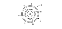
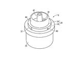
図1~図5には、本発明の1実施形態としてのニードルレスコネクター10が示されている。ニードルレスコネクター10は、ハウジング12に対して、弾性弁体としてのディスク弁14と中空弾性体16とが組み込まれた構造を有している。なお、以下の説明において、上下方向とは、原則として、図5中の上下方向を言う。また、図5中の上方を「薬液流路80の入口側」とすると共に、図5中の下方を「薬液流路80の出口側」とする。
1 to 5 show a needleless connector 10 as an embodiment of the present invention. The needleless connector 10 has a structure in which a disc valve 14 as an elastic valve body and a hollow elastic body 16 are incorporated in a housing 12. In the following description, the vertical direction means the vertical direction in FIG. 5 in principle. Further, the upper side in FIG. 5 is referred to as “the inlet side of the chemical liquid channel 80”, and the lower side in FIG. 5 is referred to as “the outlet side of the chemical channel 80”.
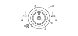
より詳細には、ハウジング12は、ベースハウジング18と収容部としてのカバーハウジング20を備えている。ベースハウジング18は、図6~図9に示されているように、合成樹脂材料の一体成形品とされており、それぞれ略円筒形状とされた筒状部22と周壁部24が径方向に所定の距離を隔てて同軸的に設けられていると共に、それら筒状部22と周壁部24が上端部において略円板形状の蓋部26で連結された構造を有している。
More specifically, the housing 12 includes a base housing 18 and a cover housing 20 as an accommodating portion. As shown in FIGS. 6 to 9, the base housing 18 is an integrally molded product of synthetic resin material, and a cylindrical portion 22 and a peripheral wall portion 24 each having a substantially cylindrical shape are predetermined in the radial direction. The cylindrical portion 22 and the peripheral wall portion 24 are connected to each other by a substantially disc-shaped lid portion 26 at the upper end portion.
筒状部22は、小径の略円筒形状を呈していると共に、外周面が下方に向かって次第に縮径するルアーテーパで構成されている。また、筒状部22の中心孔28は、上下方向で直線的に設けられて筒状部22の下面に開口していると共に、上端部が蓋部26まで至っている。
The cylindrical portion 22 has a substantially cylindrical shape with a small diameter, and is configured with a luer taper whose outer peripheral surface gradually decreases in diameter downward. Further, the center hole 28 of the cylindrical portion 22 is linearly provided in the vertical direction and opens to the lower surface of the cylindrical portion 22, and the upper end portion reaches the lid portion 26.
周壁部24は、筒状部22よりも大径の略円筒形状とされており、筒状部22に対して所定距離を隔てて外周側を取り囲むように配置されている。また、周壁部24には、内周面上に突出するようにねじ山30が形成されている。
The peripheral wall portion 24 has a substantially cylindrical shape larger in diameter than the cylindrical portion 22 and is disposed so as to surround the outer peripheral side with a predetermined distance from the cylindrical portion 22. In addition, a thread 30 is formed on the peripheral wall portion 24 so as to protrude on the inner peripheral surface.
そして、図示しない血管内留置カテーテルがベースハウジング18の筒状部22の基端開口部に対して接続されるようになっている。本実施形態では、筒状部22と周壁部24とによって雌型のルアーロック構造が構成されており、図示しない血管内留置カテーテルが確実に接続保持可能とされている。
And an intravascular indwelling catheter (not shown) is connected to the proximal end opening of the cylindrical portion 22 of the base housing 18. In the present embodiment, the tubular portion 22 and the peripheral wall portion 24 constitute a female luer lock structure, and an intravascular catheter (not shown) can be reliably connected and held.
蓋部26は、略円板形状とされており、軸方向中間部分に段差面32が設けられて、段差面32よりも下側が周壁部24よりも更に大径の大径部34とされていると共に、段差面32よりも上側が小径部36とされている。そして、大径部34の中央部分から筒状部22が下方に突出していると共に、大径部34の外周部分から周壁部24が下方に突出している。なお、図5からも明らかなように、本実施形態の蓋部26は、ハウジング12(ベースハウジング18)に一体で設けられている。
The lid portion 26 has a substantially disk shape, and is provided with a step surface 32 at an intermediate portion in the axial direction, and a large diameter portion 34 having a larger diameter than the peripheral wall portion 24 below the step surface 32. In addition, the upper side of the step surface 32 is a small diameter portion 36. The cylindrical portion 22 protrudes downward from the central portion of the large diameter portion 34, and the peripheral wall portion 24 protrudes downward from the outer peripheral portion of the large diameter portion 34. As is clear from FIG. 5, the lid portion 26 of the present embodiment is provided integrally with the housing 12 (base housing 18).
また、蓋部26には開放通路38が形成されている。この開放通路38は、図7,図8に示されているように、小径の円形孔であって、一方の端部が小径部36の上面に開口していると共に、途中で屈曲して延びて、他方の端部が大径部34の外周面に開口している。
Further, an open passage 38 is formed in the lid portion 26. The open passage 38 is a small-diameter circular hole, as shown in FIGS. 7 and 8, and has one end opening on the upper surface of the small-diameter portion 36 and bending and extending in the middle. The other end is open to the outer peripheral surface of the large diameter portion 34.
さらに、図9に示されているように、蓋部26の小径部36には、軸直角方向で貫通する連通孔40が形成されており、その両端部が小径部36の外周面に開口していると共に、長さ方向中央部分が筒状部22に形成された中心孔28の上端部に連通されている。なお、連通孔40および中心孔28と開放通路38とは相互に連通することなく独立して設けられている。
Further, as shown in FIG. 9, the small diameter portion 36 of the lid portion 26 is formed with a communication hole 40 penetrating in the direction perpendicular to the axis, and both end portions thereof open to the outer peripheral surface of the small diameter portion 36. In addition, the central portion in the length direction communicates with the upper end portion of the center hole 28 formed in the cylindrical portion 22. The communication hole 40, the center hole 28, and the open passage 38 are provided independently without communicating with each other.
さらに、蓋部26における小径部36の径方向中央部分には、上方に突出するガイド突部42が一体形成されている。このガイド突部42は、上方に向かって開口する小径の略有底円筒形状を有しており、外周面が上方に向かって次第に縮径するテーパ形状とされている。
Furthermore, a guide protrusion 42 that protrudes upward is integrally formed at a central portion in the radial direction of the small diameter portion 36 in the lid portion 26. The guide protrusion 42 has a small-diameter, substantially bottomed cylindrical shape that opens upward, and has a tapered shape with an outer peripheral surface that gradually decreases in diameter toward the upper side.
更にまた、蓋部26における小径部36の径方向中間部分には、上方に突出する変形拘束部44が一体形成されている。変形拘束部44は、ガイド突部42よりも大径の略円筒形状を有しており、ガイド突部42の外周側に所定距離を隔てて設けられている。なお、変形拘束部44は、突出先端部分の外周角部が面取り加工されており、突出先端部分の外径寸法が先端側に向かって次第に小さくなっている。
Furthermore, a deformation restraining portion 44 that protrudes upward is integrally formed at a radially intermediate portion of the small diameter portion 36 in the lid portion 26. The deformation restricting portion 44 has a substantially cylindrical shape larger in diameter than the guide protrusion 42 and is provided on the outer peripheral side of the guide protrusion 42 at a predetermined distance. In the deformation restraining portion 44, the outer peripheral corner portion of the protruding tip portion is chamfered, and the outer diameter of the protruding tip portion gradually decreases toward the tip side.
一方、カバーハウジング20は、全体として略円筒形状を有していると共に、軸方向中間部分に段差部46が形成されており、段差部46よりも下側が大径のカバー本体48とされていると共に、段差部46よりも上側が小径の接続口部50とされている。更に、カバー本体48の上部の外周面は、上方に向かって次第に縮径するテーパ形状とされている。また、接続口部50は、外周面上に突出するようにねじ山52が形成されることで雄型のルアーロックを構成している。なお、カバーハウジング20の内周面は、後述する中空弾性体16の外周面に略対応する形状とされている。
On the other hand, the cover housing 20 has a substantially cylindrical shape as a whole, and a step portion 46 is formed at an intermediate portion in the axial direction, and a cover body 48 having a large diameter is formed below the step portion 46. At the same time, a connection port portion 50 having a small diameter is formed above the step portion 46. Furthermore, the outer peripheral surface of the upper part of the cover main body 48 has a tapered shape that gradually decreases in diameter upward. Moreover, the connection port part 50 comprises the male luer lock by forming the screw thread 52 so that it may protrude on an outer peripheral surface. The inner peripheral surface of the cover housing 20 has a shape that substantially corresponds to the outer peripheral surface of the hollow elastic body 16 described later.
さらに、カバーハウジング20のカバー本体48には、凹溝としての下部連通溝54が形成されている。下部連通溝54は、カバー本体48の内周面に開口する溝であって、略一定の深さ寸法で形成されて、上下方向に延びている。本実施形態では、周上で等間隔に4条の下部連通溝54が形成されているが、下部連通溝54の数は特に限定されない。
Furthermore, a lower communication groove 54 as a concave groove is formed in the cover body 48 of the cover housing 20. The lower communication groove 54 is a groove opened on the inner peripheral surface of the cover main body 48, is formed with a substantially constant depth dimension, and extends in the vertical direction. In the present embodiment, four lower communication grooves 54 are formed at equal intervals on the circumference, but the number of lower communication grooves 54 is not particularly limited.
そして、ベースハウジング18がカバーハウジング20の下側開口部を覆うように配設されており、ベースハウジング18の大径部34にカバーハウジング20の下端面が重ね合わされて、接着や溶着、ねじによる締結等の手段で相互に固定されることにより、ハウジング12が形成されている。
The base housing 18 is disposed so as to cover the lower opening of the cover housing 20, and the lower end surface of the cover housing 20 is overlapped with the large diameter portion 34 of the base housing 18, and adhesion, welding, or screws are used. The housing 12 is formed by being fixed to each other by means such as fastening.
このハウジング12には、カバーハウジング20の内周領域を利用して収容空所56が形成されており、この収容空所56がカバーハウジング20の上側開口部を通じて上方に開口して外部空間に連通されていると共に、ベースハウジング18の連通孔40および中心孔28を通じて下方で外部空間に連通されている。なお、4条の下部連通溝54のうち2条が連通孔40と周方向で位置決めされており、下部連通溝54が下端部において連通孔40に連通されている。尤も、例えば、下部連通溝54の下端部を相互に連通するように環状の溝を形成して、この環状溝を介して下部連通溝54が連通孔40に連通されるようにすれば、ベースハウジング18とカバーハウジング20の周方向での位置決めを不要にすることもできる。
A housing space 56 is formed in the housing 12 using an inner peripheral region of the cover housing 20, and the housing space 56 opens upward through the upper opening of the cover housing 20 and communicates with the external space. In addition, it communicates with the external space below through the communication hole 40 and the center hole 28 of the base housing 18. Two of the four lower communication grooves 54 are positioned in the circumferential direction with the communication hole 40, and the lower communication groove 54 is communicated with the communication hole 40 at the lower end. However, if, for example, an annular groove is formed so that the lower end portions of the lower communication groove 54 communicate with each other, and the lower communication groove 54 communicates with the communication hole 40 via this annular groove, the base Positioning of the housing 18 and the cover housing 20 in the circumferential direction can be made unnecessary.
また、ハウジング12(カバーハウジング20)の接続口部50の上端開口部には、ディスク弁14が配設されている。ディスク弁14は、略円板形状を呈するゴム弾性体で形成されており、図1,図2に示されているように径方向一方向に延びて、厚さ方向に貫通するスリット58を備えている。そして、ディスク弁14は、カバーハウジング20の上側開口部に挿入されて保持されている。
Further, a disc valve 14 is disposed at the upper end opening of the connection port 50 of the housing 12 (cover housing 20). The disk valve 14 is formed of a rubber elastic body having a substantially disk shape, and includes a slit 58 extending in one radial direction and penetrating in the thickness direction as shown in FIGS. ing. The disc valve 14 is inserted and held in the upper opening of the cover housing 20.
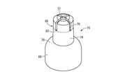
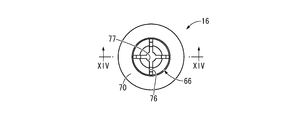
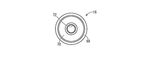
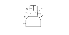
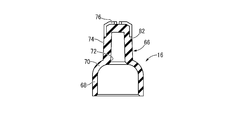
また、ディスク弁14の下方に設けられた収容空所56には、中空弾性体16が収容されて、カバーハウジング20の内周側に配設されている。中空弾性体16は、弾性材で形成されており、図10~図14に示されているように、下方に開口する逆向きの有底筒状を有すると共に、その底壁(70)の中央部分から上方に向かって突出する中央突部66を一体で備えた一体成形品とされている。
Further, the hollow elastic body 16 is accommodated in the accommodation space 56 provided below the disc valve 14 and is disposed on the inner peripheral side of the cover housing 20. The hollow elastic body 16 is formed of an elastic material, and has a bottomed cylindrical shape that opens in the downward direction as shown in FIGS. 10 to 14, and has a center of its bottom wall (70). It is an integrally formed product integrally provided with a central protrusion 66 protruding upward from the portion.
より詳細には、中空弾性体16は、シリコーンゴム等の弾性材で形成されて、一体形成された周壁68と底壁70を有しており、周壁68が略円筒形状とされていると共に、底壁70が周壁68の上端部から内周側に傾斜しながら上方に突出するテーパ形状とされている。また、底壁70の径方向中央部分には、厚さ方向(上下方向)に貫通する円形のガイド穴72が形成されており、このガイド穴72の直径がベースハウジング18に設けられたガイド突部42の最大外径寸法と同じかそれよりも大きくされることで、ガイド突部42を挿入可能とされている。なお、本実施形態の底壁70は、縦断面において軸方向に対する傾斜角度が上方に向かって次第に大きくなる湾曲形状とされている。
More specifically, the hollow elastic body 16 is formed of an elastic material such as silicone rubber, and has a peripheral wall 68 and a bottom wall 70 that are integrally formed. The peripheral wall 68 has a substantially cylindrical shape, The bottom wall 70 has a tapered shape that protrudes upward while inclining from the upper end of the peripheral wall 68 toward the inner peripheral side. Further, a circular guide hole 72 penetrating in the thickness direction (vertical direction) is formed in the central portion of the bottom wall 70 in the radial direction, and the diameter of the guide hole 72 is a guide protrusion provided in the base housing 18. The guide protrusion 42 can be inserted by making it equal to or larger than the maximum outer diameter of the portion 42. Note that the bottom wall 70 of the present embodiment has a curved shape in which the inclination angle with respect to the axial direction gradually increases upward in the longitudinal section.
中央突部66は、下方に向かって開口する逆向きの略有底円筒形状を有しており、弾性材によって中空弾性体16と一体形成されて、中空弾性体16の底壁70におけるガイド穴72の開口周縁部から上方に突出している。このように、中空弾性体16が中央突部66を含んで弾性材で一体形成された一体成形品とされていることで、部品点数の削減と構造の簡易化が図られている。
The central protrusion 66 has a substantially bottomed cylindrical shape that is open in the downward direction and is integrally formed with the hollow elastic body 16 by an elastic material, so that a guide hole in the bottom wall 70 of the hollow elastic body 16 is formed. Projecting upward from the peripheral edge of the opening 72. As described above, the hollow elastic body 16 is formed as an integrally molded product including the central protrusion 66 and integrally formed of an elastic material, thereby reducing the number of parts and simplifying the structure.
また、中央突部66は、中空弾性体16の底壁70および周壁68に比して厚肉とされており、後述する雄ルアー86での押込力が中央突部66に対して及ぼされることで、底壁70の変形が中央突部66の変形よりも優先的に生じるようになっている。
Further, the central protrusion 66 is thicker than the bottom wall 70 and the peripheral wall 68 of the hollow elastic body 16, and the pushing force at the male luer 86 described later is exerted on the central protrusion 66. Thus, the deformation of the bottom wall 70 occurs preferentially over the deformation of the central protrusion 66.
さらに、中央突部66の周壁部は基端側(下側)に向かって次第に大径となるテーパ形状を有しており、後述する上部連通溝76よりも下方において中央突部66の外周面が突出先端側に向かって小径となるテーパ面74で構成されている。また、中央突部66の内周領域は下方に向かって次第に大径となるテーパ穴形状とされて、中空弾性体16のガイド穴72を通じて下方に開口しており、本実施形態においてガイド穴72の一部を構成している。
Further, the peripheral wall portion of the central protrusion 66 has a tapered shape that gradually becomes larger in diameter toward the base end side (lower side), and the outer peripheral surface of the central protrusion 66 is below the upper communication groove 76 described later. Is formed of a tapered surface 74 having a smaller diameter toward the protruding tip side. Further, the inner peripheral region of the central protrusion 66 has a tapered hole shape that gradually increases in diameter downward, and opens downward through the guide hole 72 of the hollow elastic body 16, and in this embodiment, the guide hole 72. Part of.
また、中央突部66の上端部分には、上部連通溝76が形成されている。上部連通溝76は、中央突部66の上面に開口して径方向2方向に延びる十字形状を呈して外周端部まで至っている(図11参照)と共に、外周端部から軸方向下方に向かって直線的に延びて中央突部66の上端部分の外周面に開口している(図13参照)。なお、本実施形態では、中央突部66の上面の径方向中央部分に円形の凹所77が開口形成されており、この凹所77が上部連通溝76に連通されている。
Further, an upper communication groove 76 is formed at the upper end portion of the central protrusion 66. The upper communication groove 76 opens to the upper surface of the central protrusion 66 and has a cross shape extending in two radial directions to reach the outer peripheral end (see FIG. 11), and from the outer peripheral end toward the lower side in the axial direction. It extends linearly and opens on the outer peripheral surface of the upper end portion of the central protrusion 66 (see FIG. 13). In the present embodiment, a circular recess 77 is formed in the central portion of the upper surface of the central protrusion 66 in the radial direction, and the recess 77 communicates with the upper communication groove 76.
このような構造とされた中空弾性体16は、ハウジング12の収容空所56に収容配置されている。即ち、中空弾性体16は、ベースハウジング18とディスク弁14の軸方向対向面間に配設されており、下方への開口部がベースハウジング18の蓋部26で覆蓋されている。また、中空弾性体16とベースハウジング18の蓋部26との間には、変形許容空間78が形成されており、この変形許容空間78が蓋部26の開放通路38を通じて外部空間に連通されている。
The hollow elastic body 16 having such a structure is accommodated in the accommodation space 56 of the housing 12. That is, the hollow elastic body 16 is disposed between the axially opposed surfaces of the base housing 18 and the disk valve 14, and the downward opening is covered with the lid portion 26 of the base housing 18. Further, a deformation allowable space 78 is formed between the hollow elastic body 16 and the lid portion 26 of the base housing 18, and the deformation allowable space 78 communicates with the external space through the open passage 38 of the lid portion 26. Yes.
さらに、中空弾性体16の下側開口部からベースハウジング18の変形拘束部44が挿入されて、周壁68の内周面に重ね合わされており、中空弾性体16の周壁68が変形拘束部44とカバーハウジング20の間で挟持されている。なお、中空弾性体16の収容空所56への配設状態において、ベースハウジング18のガイド突部42は、中空弾性体16の底壁70の下面よりも下方に位置して、底壁70の中央部分に向かって突出しており、中空弾性体16のガイド穴72に対して軸直角方向で位置決めされて下方に離隔配置されている。
Further, the deformation restraining portion 44 of the base housing 18 is inserted from the lower opening of the hollow elastic body 16 and overlapped with the inner peripheral surface of the peripheral wall 68, and the peripheral wall 68 of the hollow elastic body 16 is connected to the deformation restraining portion 44. It is sandwiched between the cover housings 20. When the hollow elastic body 16 is disposed in the accommodation space 56, the guide protrusion 42 of the base housing 18 is positioned below the bottom surface of the bottom wall 70 of the hollow elastic body 16, and It protrudes toward the central portion, is positioned in a direction perpendicular to the axis with respect to the guide hole 72 of the hollow elastic body 16, and is spaced apart downward.
また、中空弾性体16が収容空所56に配設されることによって、中空弾性体16の外周面は、カバーハウジング20の内周面に対して、隙間なく密着して或いは薬液等の漏れや残留が問題とならない程度に小さな隙間をもって重ね合わされている。これにより、カバーハウジング20に形成された下部連通溝54の開口部が中空弾性体16で覆われて、カバーハウジング20と中空弾性体16の間にトンネル状の流路が形成されている。そのトンネル状流路がベースハウジング18の連通孔40および中心孔28に連通されていることにより、少なくとも一部(下部連通溝54で構成された部分)においてハウジング12と中空弾性体16の間を延びる薬液流路80が形成されている。このように、カバーハウジング20の内周面に開口する下部連通溝54を形成すれば、中空弾性体16の配設によって、ハウジング12と中空弾性体16の間に薬液流路80を容易に形成することができる。
In addition, since the hollow elastic body 16 is disposed in the accommodation space 56, the outer peripheral surface of the hollow elastic body 16 is in close contact with the inner peripheral surface of the cover housing 20 without any gaps or leakage of a chemical solution or the like. They are stacked with a small gap so that the residue does not become a problem. Accordingly, the opening of the lower communication groove 54 formed in the cover housing 20 is covered with the hollow elastic body 16, and a tunnel-like flow path is formed between the cover housing 20 and the hollow elastic body 16. The tunnel-shaped flow path communicates with the communication hole 40 and the center hole 28 of the base housing 18, so that at least a part (a part constituted by the lower communication groove 54) is formed between the housing 12 and the hollow elastic body 16. An extending chemical liquid flow path 80 is formed. Thus, if the lower communication groove 54 opened on the inner peripheral surface of the cover housing 20 is formed, the chemical flow path 80 is easily formed between the housing 12 and the hollow elastic body 16 by the arrangement of the hollow elastic body 16. can do.
更にまた、中空弾性体16の外周面がカバーハウジング20の内周面に重ね合わされることによって、中央突部66に形成された上部連通溝76の開口部がカバーハウジング20で覆われて、カバーハウジング20と中空弾性体16の間にトンネル状の流路が形成されている。
Furthermore, the outer peripheral surface of the hollow elastic body 16 is overlapped with the inner peripheral surface of the cover housing 20, so that the opening of the upper communication groove 76 formed in the central protrusion 66 is covered with the cover housing 20. A tunnel-like flow path is formed between the housing 20 and the hollow elastic body 16.
また、下部連通溝54の上端部が上部連通溝76の下端部までは至らずに下方に離隔して位置しており、中央突部66における上部連通溝76の下壁部で構成された弁座部82が、カバーハウジング20における下部連通溝54の上壁部に対して当接している。これにより、下部連通溝54と上部連通溝76が弁座部82で隔てられており、薬液流路80が弁座部82によって流路長方向の中間部分で遮断されている。
Further, the upper end portion of the lower communication groove 54 does not reach the lower end portion of the upper communication groove 76 and is spaced apart downward, and a valve formed by the lower wall portion of the upper communication groove 76 in the central protrusion 66. The seat portion 82 is in contact with the upper wall portion of the lower communication groove 54 in the cover housing 20. Thus, the lower communication groove 54 and the upper communication groove 76 are separated by the valve seat portion 82, and the chemical flow path 80 is blocked by the valve seat section 82 at an intermediate portion in the flow path length direction.
かくの如き構造とされたニードルレスコネクター10は、前述のように薬液流路80の基端開口部に対してカテーテル等が接続されて使用される。そして、かかる使用状態下、図15に示されているように、上方からシリンジ84等の雄ルアー86がハウジング12の接続口部50から挿し入れられることにより、ディスク弁14のスリット58が拡開される。
The needleless connector 10 having such a structure is used with a catheter or the like connected to the proximal end opening of the chemical liquid flow path 80 as described above. Then, as shown in FIG. 15, a male luer 86 such as a syringe 84 is inserted from above through the connection port 50 of the housing 12, so that the slit 58 of the disc valve 14 is expanded. Is done.
なお、図15に示されたシリンジ84の雄ルアー86は、雄型のルアーロック構造とされており、カバーハウジング20の接続口部50に対する接続状態が確実に維持されるようになっている。この雄ルアー86は、ねじで固定するルアーロック構造だけでなく、挿し込んで固定するルアースリップ構造であっても良い。
The male luer 86 of the syringe 84 shown in FIG. 15 has a male luer lock structure so that the connection state with respect to the connection port 50 of the cover housing 20 is reliably maintained. The male luer 86 may have not only a luer lock structure that is fixed by screws, but also a luer slip structure that is inserted and fixed.
ここにおいて、ニードルレスコネクター10では、スリット58に雄ルアー86を挿し入れた際に、雄ルアー86の押込力が中空弾性体16に及ぼされて、弁座部82による上下連通溝76,54の遮断が解除されることで、雄ルアー86が薬液流路80に連通状態とされるようになっている。
Here, in the needleless connector 10, when the male luer 86 is inserted into the slit 58, the pushing force of the male luer 86 is exerted on the hollow elastic body 16, and the upper and lower communication grooves 76, 54 formed by the valve seat portion 82. By releasing the blocking, the male luer 86 is brought into communication with the chemical liquid flow path 80.
より具体的には、ディスク弁14のスリット58を貫通して挿入された雄ルアー86が中空弾性体16の中央突部66を下方に押し込むことで、中央突部66が下方に変位して、中央突部66の弁座部82とハウジング12の内周面との当接が解除される。これにより、下部連通溝54と上部連通溝76が相互に連通されて、雄ルアー86が薬液流路80に連通される。このように薬液流路80は、ハウジング12を長さ方向である上下に貫通するように設けられており、その入口がハウジング12の上端部に配設されたディスク弁14のスリット58とされていると共に、出口がハウジング12の下端部に設けられた筒状部22の中心孔28とされている。
More specifically, the male luer 86 inserted through the slit 58 of the disc valve 14 pushes the central protrusion 66 of the hollow elastic body 16 downward, so that the central protrusion 66 is displaced downward, The contact between the valve seat 82 of the central protrusion 66 and the inner peripheral surface of the housing 12 is released. Accordingly, the lower communication groove 54 and the upper communication groove 76 are communicated with each other, and the male luer 86 is communicated with the chemical liquid flow path 80. In this way, the chemical liquid flow path 80 is provided so as to penetrate the housing 12 in the vertical direction, which is the length direction, and the inlet thereof is a slit 58 of the disc valve 14 disposed at the upper end portion of the housing 12. In addition, the outlet is a central hole 28 of the cylindrical portion 22 provided at the lower end portion of the housing 12.
そこにおいて、中央突部66が雄ルアー86で下方に押し込まれることによって、中空弾性体16の底壁70の内周部分が下方に押し下げられる。かかる押し下げに伴って、中空弾性体16は底壁70の内周部分が周壁68の内周側(変形許容空間78内)に入り込むように弾性変形される。これにより、中空弾性体16の底壁70がカバーハウジング20の内周面から離隔して、ハウジング12と中空弾性体16の間に形成された薬液流路80の容積が、積極的に増大することとなる。それ故、雄ルアー86を抜き取った際に、中空弾性体16の形状復元分に相当する量の容積減少が、ニードルレスコネクター10の薬液流路80に陽圧(正圧)を発生することとなり、血液等の逆流防止効果が発揮されるのである。
Here, when the central protrusion 66 is pushed downward by the male luer 86, the inner peripheral portion of the bottom wall 70 of the hollow elastic body 16 is pushed downward. With this depression, the hollow elastic body 16 is elastically deformed so that the inner peripheral portion of the bottom wall 70 enters the inner peripheral side of the peripheral wall 68 (within the deformation allowable space 78). Thereby, the bottom wall 70 of the hollow elastic body 16 is separated from the inner peripheral surface of the cover housing 20, and the volume of the chemical liquid flow path 80 formed between the housing 12 and the hollow elastic body 16 is positively increased. It will be. Therefore, when the male luer 86 is extracted, the volume reduction corresponding to the shape restoration of the hollow elastic body 16 generates a positive pressure (positive pressure) in the chemical liquid flow path 80 of the needleless connector 10. The effect of preventing the backflow of blood and the like is exhibited.
換言すれば、収容空所56が中空弾性体16を挟んで内周側の変形許容空間78と外周側の薬液流路80とに分けられており、雄ルアー86の押込力が作用して中空弾性体16が弾性変形することで、それら変形許容空間78と薬液流路80の容積比が変化するようになっている。そして、薬液流路80の連通時には、底壁70が周壁68内に入り込むことで、変形許容空間78の容積が減少すると共に薬液流路80の容積が増大する。一方、薬液流路80の遮断時には、底壁70が周壁68内から外側に出ることで、変形許容空間78の容積が増大すると共に薬液流路80の容積が減少することから、薬液流路80に陽圧が発生するようになっている。
In other words, the accommodation space 56 is divided into the inner peripheral deformation allowable space 78 and the outer peripheral chemical liquid flow channel 80 with the hollow elastic body 16 in between, and the pushing force of the male luer 86 acts to be hollow. When the elastic body 16 is elastically deformed, the volume ratio between the deformation allowable space 78 and the chemical liquid flow path 80 is changed. When the chemical liquid flow path 80 is in communication, the bottom wall 70 enters the peripheral wall 68, whereby the volume of the deformation allowable space 78 decreases and the volume of the chemical liquid flow path 80 increases. On the other hand, when the chemical liquid flow path 80 is shut off, the bottom wall 70 protrudes from the inside of the peripheral wall 68 to increase the volume of the deformation allowable space 78 and decrease the volume of the chemical liquid flow path 80. Positive pressure is generated in the.
特に本実施形態のニードルレスコネクター10では、中空弾性体16の周壁68がカバーハウジング20とベースハウジング18の変形拘束部44との間で挟まれて、変形が制限されている。それ故、中央突部66が雄ルアー86で押し込まれる際に、中空弾性体16が外側に膨出変形することはなく、底壁70が周壁68内に入り込むように安定して弾性変形することから、薬液流路80が高い信頼性で連通状態に切り替えられると共に、薬液流路80の容積変化を利用した逆流防止効果が確実に発揮される。
Particularly, in the needleless connector 10 of the present embodiment, the peripheral wall 68 of the hollow elastic body 16 is sandwiched between the cover housing 20 and the deformation restraining portion 44 of the base housing 18 to restrict deformation. Therefore, when the central protrusion 66 is pushed by the male luer 86, the hollow elastic body 16 does not bulge outward and is stably elastically deformed so that the bottom wall 70 enters the peripheral wall 68. Therefore, the chemical liquid flow path 80 is switched to the communication state with high reliability, and the backflow preventing effect using the volume change of the chemical liquid flow path 80 is reliably exhibited.
また、中空弾性体16の外周面がカバーハウジング20の内周面と略対応する形状とされており、それら中空弾性体16の外周面とカバーハウジング20の内周面とが上下の連通溝76,54を外れた部分で隙間なく或いは極小さな隙間を介して重ね合わされている。それ故、雄ルアー86の抜き取りによって中空弾性体16が変形状態から初期形状に復帰することで、カバーハウジング20と中空弾性体16の間の薬液等が残留することなく出口側に押し出されて、目的とする分量の薬液等を確実に出口側に送出することができる。
The outer peripheral surface of the hollow elastic body 16 has a shape substantially corresponding to the inner peripheral surface of the cover housing 20, and the upper and lower communication grooves 76 are formed between the outer peripheral surface of the hollow elastic body 16 and the inner peripheral surface of the cover housing 20. , 54 are overlapped with no gap or through a very small gap at a portion outside 54. Therefore, by extracting the male luer 86, the hollow elastic body 16 returns to the initial shape from the deformed state, so that the chemical solution between the cover housing 20 and the hollow elastic body 16 is pushed out to the outlet side without remaining, It is possible to reliably deliver a target amount of chemical solution or the like to the outlet side.
さらに、薬液流路80を構成する上下の連通溝76,54が、上部連通溝76の一部を除いた広範囲に亘って上下方向に延びていることから、薬液流路80内の薬液等が重力の作用によって出口側に自動的に導かれて、出口(中心孔28)から外部に排出される。このように、薬液流路80の形状(延びる向き)によっても、薬液流路80内への薬液の残留が防止されている。
Furthermore, since the upper and lower communication grooves 76 and 54 constituting the chemical liquid flow path 80 extend in the vertical direction over a wide range excluding a part of the upper communication groove 76, the chemical liquid and the like in the chemical liquid flow path 80 can be obtained. It is automatically guided to the outlet side by the action of gravity, and discharged from the outlet (center hole 28) to the outside. As described above, the remaining of the chemical liquid in the chemical liquid flow path 80 is also prevented by the shape (extending direction) of the chemical liquid flow path 80.
さらに、中央突部66が雄ルアー86で押し下げられることにより、ベースハウジング18に設けられたガイド突部42が、中空弾性体16の底壁70に形成されたガイド穴72に挿入されるようになっている。これにより、中央突部66が倒れるように変形する等の歪な変形が防止されて、中空弾性体16が目的とする変形態様で安定して弾性変形することから、薬液流路80の連通状態への切替えと、血液等の逆流防止作用が、何れも安定して実現される。
Further, the central protrusion 66 is pushed down by the male luer 86 so that the guide protrusion 42 provided on the base housing 18 is inserted into the guide hole 72 formed in the bottom wall 70 of the hollow elastic body 16. It has become. This prevents distortion deformation such as deformation of the central projection 66 so that it falls down, and the hollow elastic body 16 is stably elastically deformed in the intended deformation mode. Both the switching to and the action of preventing the backflow of blood or the like can be realized stably.
特に本実施形態では、ガイド穴72が開口側に向かって拡径するテーパ形状とされていると共に、ガイド突部42が突出先端側に向かって縮径するテーパ形状とされている。これにより、ガイド突部42がガイド穴72に確実に挿入されるようになっており、ガイド突部42のガイド穴72への挿入による案内作用が確実に発揮されて、中空弾性体16の弾性変形後の形態が安定する。
Particularly in the present embodiment, the guide hole 72 has a tapered shape in which the diameter increases toward the opening side, and the guide protrusion 42 has a tapered shape in which the diameter decreases toward the protruding tip side. As a result, the guide protrusion 42 is reliably inserted into the guide hole 72, and the guide action by the insertion of the guide protrusion 42 into the guide hole 72 is reliably exhibited, so that the elasticity of the hollow elastic body 16 is increased. The shape after deformation is stable.
また、ディスク弁14による雄ルアー86と薬液流路80の接続と解除の切り替えに加えて、中空弾性体16の弁座部82がハウジング12の内周面に当接することによっても薬液流路80が遮断されるようになっている。このように2重の弁手段が設けられていることから、薬液や血液等の入口側への漏れが効果的に防止される。
Further, in addition to switching between connection and release of the male luer 86 and the chemical flow path 80 by the disk valve 14, the chemical flow path 80 is also brought about when the valve seat portion 82 of the hollow elastic body 16 abuts on the inner peripheral surface of the housing 12. Is to be blocked. Since the double valve means is provided in this way, leakage of the chemical liquid or blood to the inlet side is effectively prevented.
以上、本発明の実施形態について詳述してきたが、本発明はその具体的な記載によって限定されない。例えば、中空弾性体の形状は、前記実施形態に示された具体的な形状によって限定的に解釈されるものではない。具体的には、例えば、底壁の形状は、前記実施形態に示されているような湾曲断面を有する形状の他、軸直角方向に広がる平板状や、略一定の傾斜角度で傾斜するテーパ状等であっても良い。
As mentioned above, although embodiment of this invention has been explained in full detail, this invention is not limited by the specific description. For example, the shape of the hollow elastic body is not limitedly interpreted by the specific shape shown in the embodiment. Specifically, for example, the shape of the bottom wall has a curved cross section as shown in the above embodiment, a flat plate shape extending in a direction perpendicular to the axis, or a tapered shape inclined at a substantially constant inclination angle. Etc.
さらに、弁座部は、中央突部66ではなく底壁70に設けることも可能であるし、設けられていなくても良い。複数の弁座部を設けて、薬液流路80の遮断性能をより向上させることも可能である。
Furthermore, the valve seat portion can be provided not on the central protrusion 66 but on the bottom wall 70 or may not be provided. It is also possible to improve the blocking performance of the chemical liquid flow path 80 by providing a plurality of valve seat portions.
更にまた、中央突部は、前記実施形態に示された中空形状のものに限定されず、中実の柱状であっても良い。この場合には、前記実施形態においてベースハウジング18に設けられていたガイド突部42は、中空弾性体16の底壁70の厚さに相当する突出高さの小さいものとされるか、或いは省略される。
Furthermore, the central protrusion is not limited to the hollow shape shown in the embodiment, and may be a solid column. In this case, the guide protrusion 42 provided on the base housing 18 in the above embodiment has a small protrusion height corresponding to the thickness of the bottom wall 70 of the hollow elastic body 16 or is omitted. Is done.
また、中空弾性体の底壁の肉厚を周壁の肉厚よりも小さくしても良い。このようにすれば、中空弾性体が底壁の部分で弾性変形し易くなることから、雄ルアーを挿入した際に、底壁の周壁内周側に入り込むような弾性変形がより確実に実現される。
Further, the thickness of the bottom wall of the hollow elastic body may be smaller than the thickness of the peripheral wall. In this way, since the hollow elastic body is easily elastically deformed at the bottom wall portion, when the male luer is inserted, elastic deformation that enters the inner peripheral side of the peripheral wall of the bottom wall is more reliably realized. The
また、前記実施形態では、蓋部26がベースハウジング18に一体で設けられていたが、蓋部はハウジングとは別体の部材で構成されていても良い。
In the embodiment, the lid portion 26 is provided integrally with the base housing 18, but the lid portion may be formed of a member separate from the housing.
さらに、中央突部は、中空弾性体とは別体で形成されていても良く、その場合には、それら中央突部と中空弾性体が接着や溶着等の手段で後固定され得る。なお、中央突部が弾性材で形成されていることは必須ではなく、例えば硬質の合成樹脂等で形成することも可能である。
Furthermore, the central protrusion may be formed separately from the hollow elastic body, and in this case, the central protrusion and the hollow elastic body can be fixed later by means such as adhesion or welding. In addition, it is not essential that the central protrusion is formed of an elastic material, and for example, it can be formed of a hard synthetic resin or the like.
また、前記実施形態にも例示されているように、カバーハウジング20の内周面と中空弾性体16および中央突部66の外周面との何れか一方或いは両方に形成された凹溝が覆蓋されることによって、薬液流路80が形成され得る。
Further, as exemplified in the above-described embodiment, a concave groove formed on one or both of the inner peripheral surface of the cover housing 20 and the outer peripheral surfaces of the hollow elastic body 16 and the central protrusion 66 is covered. Accordingly, the chemical liquid flow path 80 can be formed.
また、前記実施形態において、中空弾性体はシリコーンゴムで形成されているが、本発明の趣旨に沿うものであればその材質は問わない。好ましくは、シリコーンゴム、合成ゴム、天然ゴム、熱可塑性エラストマー等が使用される。
In the above embodiment, the hollow elastic body is formed of silicone rubber, but any material can be used as long as it conforms to the gist of the present invention. Preferably, silicone rubber, synthetic rubber, natural rubber, thermoplastic elastomer and the like are used.
また、前記実施形態において、中空弾性体は、雄ルアーにより中央突部が下方に押される構成であるが、例えば、雄ルアーと中空弾性体の間にそれらとは別体の押し子を設けてハウジング内に可動に配置し、雄ルアーによって移動される当該押し子により、中空弾性体の中央突部が押圧変形される構成であっても良い。
Moreover, in the said embodiment, although a hollow elastic body is a structure by which a center protrusion is pushed below by a male luer, for example, providing a pushing element separate from them between a male luer and a hollow elastic body A configuration in which the central protrusion of the hollow elastic body is pressed and deformed by the pusher which is movably disposed in the housing and moved by the male luer may be employed.