WO2013118673A1 - Mixing device, discharge device provided therewith, and discharge method - Google Patents

Mixing device, discharge device provided therewith, and discharge method Download PDF

Info

Publication number
WO2013118673A1
WO2013118673A1 PCT/JP2013/052455 JP2013052455W WO2013118673A1 WO 2013118673 A1 WO2013118673 A1 WO 2013118673A1 JP 2013052455 W JP2013052455 W JP 2013052455W WO 2013118673 A1 WO2013118673 A1 WO 2013118673A1
Authority
WO
WIPO (PCT)
Prior art keywords
stirrer
stirring
container
discharge
liquid
Prior art date
Application number
PCT/JP2013/052455
Other languages
French (fr)
Japanese (ja)
Inventor
生島 和正
Original Assignee
武蔵エンジニアリング株式会社
Priority date (The priority date is an assumption and is not a legal conclusion. Google has not performed a legal analysis and makes no representation as to the accuracy of the date listed.)
Filing date
Publication date
Application filed by 武蔵エンジニアリング株式会社 filed Critical 武蔵エンジニアリング株式会社
Priority to US14/376,735 priority Critical patent/US10315173B2/en
Priority to CN201380008448.1A priority patent/CN104168992B/en
Priority to EP13746864.1A priority patent/EP2813282B1/en
Priority to SG11201404617SA priority patent/SG11201404617SA/en
Priority to KR1020147024930A priority patent/KR102043769B1/en
Publication of WO2013118673A1 publication Critical patent/WO2013118673A1/en
Priority to HK15100951.0A priority patent/HK1200396A1/en

Links

Images

Classifications

    • BPERFORMING OPERATIONS; TRANSPORTING
    • B01PHYSICAL OR CHEMICAL PROCESSES OR APPARATUS IN GENERAL
    • B01FMIXING, e.g. DISSOLVING, EMULSIFYING OR DISPERSING
    • B01F33/00Other mixers; Mixing plants; Combinations of mixers
    • B01F33/45Magnetic mixers; Mixers with magnetically driven stirrers
    • BPERFORMING OPERATIONS; TRANSPORTING
    • B01PHYSICAL OR CHEMICAL PROCESSES OR APPARATUS IN GENERAL
    • B01FMIXING, e.g. DISSOLVING, EMULSIFYING OR DISPERSING
    • B01F23/00Mixing according to the phases to be mixed, e.g. dispersing or emulsifying
    • B01F23/50Mixing liquids with solids
    • B01F23/53Mixing liquids with solids using driven stirrers
    • BPERFORMING OPERATIONS; TRANSPORTING
    • B01PHYSICAL OR CHEMICAL PROCESSES OR APPARATUS IN GENERAL
    • B01FMIXING, e.g. DISSOLVING, EMULSIFYING OR DISPERSING
    • B01F23/00Mixing according to the phases to be mixed, e.g. dispersing or emulsifying
    • B01F23/50Mixing liquids with solids
    • BPERFORMING OPERATIONS; TRANSPORTING
    • B01PHYSICAL OR CHEMICAL PROCESSES OR APPARATUS IN GENERAL
    • B01FMIXING, e.g. DISSOLVING, EMULSIFYING OR DISPERSING
    • B01F27/00Mixers with rotary stirring devices in fixed receptacles; Kneaders
    • B01F27/05Stirrers
    • B01F27/07Stirrers characterised by their mounting on the shaft
    • B01F27/072Stirrers characterised by their mounting on the shaft characterised by the disposition of the stirrers with respect to the rotating axis
    • B01F27/0721Stirrers characterised by their mounting on the shaft characterised by the disposition of the stirrers with respect to the rotating axis parallel with respect to the rotating axis
    • BPERFORMING OPERATIONS; TRANSPORTING
    • B01PHYSICAL OR CHEMICAL PROCESSES OR APPARATUS IN GENERAL
    • B01FMIXING, e.g. DISSOLVING, EMULSIFYING OR DISPERSING
    • B01F27/00Mixers with rotary stirring devices in fixed receptacles; Kneaders
    • B01F27/05Stirrers
    • B01F27/07Stirrers characterised by their mounting on the shaft
    • B01F27/072Stirrers characterised by their mounting on the shaft characterised by the disposition of the stirrers with respect to the rotating axis
    • B01F27/0724Stirrers characterised by their mounting on the shaft characterised by the disposition of the stirrers with respect to the rotating axis directly mounted on the rotating axis
    • BPERFORMING OPERATIONS; TRANSPORTING
    • B01PHYSICAL OR CHEMICAL PROCESSES OR APPARATUS IN GENERAL
    • B01FMIXING, e.g. DISSOLVING, EMULSIFYING OR DISPERSING
    • B01F27/00Mixers with rotary stirring devices in fixed receptacles; Kneaders
    • B01F27/05Stirrers
    • B01F27/11Stirrers characterised by the configuration of the stirrers
    • B01F27/112Stirrers characterised by the configuration of the stirrers with arms, paddles, vanes or blades
    • B01F27/1125Stirrers characterised by the configuration of the stirrers with arms, paddles, vanes or blades with vanes or blades extending parallel or oblique to the stirrer axis
    • BPERFORMING OPERATIONS; TRANSPORTING
    • B01PHYSICAL OR CHEMICAL PROCESSES OR APPARATUS IN GENERAL
    • B01FMIXING, e.g. DISSOLVING, EMULSIFYING OR DISPERSING
    • B01F27/00Mixers with rotary stirring devices in fixed receptacles; Kneaders
    • B01F27/05Stirrers
    • B01F27/11Stirrers characterised by the configuration of the stirrers
    • B01F27/19Stirrers with two or more mixing elements mounted in sequence on the same axis
    • B01F27/191Stirrers with two or more mixing elements mounted in sequence on the same axis with similar elements
    • BPERFORMING OPERATIONS; TRANSPORTING
    • B01PHYSICAL OR CHEMICAL PROCESSES OR APPARATUS IN GENERAL
    • B01FMIXING, e.g. DISSOLVING, EMULSIFYING OR DISPERSING
    • B01F33/00Other mixers; Mixing plants; Combinations of mixers
    • B01F33/45Magnetic mixers; Mixers with magnetically driven stirrers
    • B01F33/453Magnetic mixers; Mixers with magnetically driven stirrers using supported or suspended stirring elements
    • B01F33/4534Magnetic mixers; Mixers with magnetically driven stirrers using supported or suspended stirring elements using a rod for supporting the stirring element, e.g. stirrer sliding on a rod or mounted on a rod sliding in a tube
    • BPERFORMING OPERATIONS; TRANSPORTING
    • B01PHYSICAL OR CHEMICAL PROCESSES OR APPARATUS IN GENERAL
    • B01FMIXING, e.g. DISSOLVING, EMULSIFYING OR DISPERSING
    • B01F35/00Accessories for mixers; Auxiliary operations or auxiliary devices; Parts or details of general application
    • B01F35/75Discharge mechanisms
    • B01F35/754Discharge mechanisms characterised by the means for discharging the components from the mixer
    • B01F35/75425Discharge mechanisms characterised by the means for discharging the components from the mixer using pistons or plungers
    • B01F35/754251Discharge mechanisms characterised by the means for discharging the components from the mixer using pistons or plungers reciprocating in the mixing receptacle
    • BPERFORMING OPERATIONS; TRANSPORTING
    • B01PHYSICAL OR CHEMICAL PROCESSES OR APPARATUS IN GENERAL
    • B01FMIXING, e.g. DISSOLVING, EMULSIFYING OR DISPERSING
    • B01F35/00Accessories for mixers; Auxiliary operations or auxiliary devices; Parts or details of general application
    • B01F35/75Discharge mechanisms
    • B01F35/754Discharge mechanisms characterised by the means for discharging the components from the mixer
    • B01F35/7543Discharge mechanisms characterised by the means for discharging the components from the mixer using pneumatic pressure, overpressure or gas pressure in a closed receptacle or circuit system

Landscapes

  • Chemical & Material Sciences (AREA)
  • Chemical Kinetics & Catalysis (AREA)
  • Dispersion Chemistry (AREA)
  • Mixers With Rotating Receptacles And Mixers With Vibration Mechanisms (AREA)
  • Accessories For Mixers (AREA)
  • Mixers Of The Rotary Stirring Type (AREA)

Abstract

Problem: To provide a mixing device which resolves problems resulting from friction between the vessel and the stirrers, which can create a circulatory flow even below the stirrers, and in which a desired number of stirrers can be arranged in desired positions; and to provide a discharge device provided with said mixing device, and a discharge method. Solution: A mixing device is characterized by being provided with stirrers having magnets, a stirrer holding mechanism which defines the positions of the stirrers by exerting a magnetic force laterally on the stirrers, and a rotation mechanism which rotates the stirrer holding mechanism, wherein the rotation mechanism rotates the stirrer holding mechanism, thereby rotating the stirrers; and a discharge device provided with said mixing device, and a discharge method.

Description

攪拌装置およびそれを備える吐出装置並びに吐出方法Stirring device, discharge device including the same and discharge method
 本発明は、固体粒子を混合した液体を攪拌して、均一な混合状態を保つ攪拌装置、およびこの攪拌装置を備える吐出装置並びに吐出方法に関する。 The present invention relates to a stirring device that stirs a liquid in which solid particles are mixed to maintain a uniform mixed state, and a discharge device and a discharge method including the stirring device.
 液体よりも比重の大きい固体粒子を混合した液体中では、時間が経過するにつれ固体粒子が沈降して均一な混合状態を保つことが難しい。均一な混合状態を保つには、攪拌装置を設け、固体粒子混合液体を貯留した容器内で攪拌し続けることが必要である。 In a liquid in which solid particles having a specific gravity greater than that of the liquid are mixed, it is difficult to maintain a uniform mixed state because the solid particles settle as time passes. In order to maintain a uniform mixed state, it is necessary to provide a stirring device and continue stirring in a container in which the solid particle mixed liquid is stored.
 攪拌装置には、モータ動力軸に接続したロッドの先端に羽根状部材を設け、これを固体粒子混合液体中で回転させて混合を行うモータタイプや、磁石や磁性体を内設した攪拌子を固体粒子混合液体中に入れ、これを容器の外から磁力の作用により回転させて混合を行う磁力タイプなどがよく用いられる。 The stirrer is equipped with a blade type member at the tip of the rod connected to the motor power shaft, and a motor type that mixes by rotating this in a solid particle mixed liquid, or a stirrer with an internal magnet or magnetic body A magnetic type or the like is often used in which a solid particle mixed liquid is placed in a liquid mixture and rotated by the action of a magnetic force from outside the container.
 ところで、前述の固体粒子混合液体を容器から定量的に吐出、分配する際には、液体材料の吐出、分配に一般的に用いられている吐出装置を用いる。固体粒子混合液体を扱う吐出装置においても、均一な混合状態を保つには、前述の各種タイプの攪拌装置を設けることが必要である。攪拌を行わなければ、不均一な状態で吐出されたり、或いは吐出口が詰まって吐出できないといった事態が発生する。 By the way, when the above-mentioned solid particle mixed liquid is quantitatively discharged and distributed from the container, a discharge device generally used for discharging and distributing the liquid material is used. Even in a discharge device that handles a solid particle mixed liquid, it is necessary to provide the above-described various types of stirring devices in order to maintain a uniform mixed state. If the agitation is not performed, a situation may occur in which ejection is performed in a non-uniform state or the ejection port is clogged and cannot be ejected.
 吐出装置に攪拌装置を設けている例として、特許文献1のような装置がある。特許文献1には、容器と、液体を攪拌する攪拌子と、攪拌子を磁力により回転させる攪拌子回転手段とを具備した吐出装置であって、容器に貯留された液体を吐出する吐出装置の容器内底部に攪拌子を配置し、攪拌子には上下面を貫通する貫通孔が穿設され、上面に突起が設けられ、外周面と貫通孔とを連通する溝が下面に形成されている吐出装置が開示されている。 As an example in which a stirring device is provided in the discharge device, there is a device as in Patent Document 1. Patent Document 1 discloses a discharge device that includes a container, a stirrer that stirs the liquid, and a stirrer rotating unit that rotates the stirrer with a magnetic force, and discharges the liquid stored in the container. A stirrer is disposed at the bottom of the container, the stirrer is provided with a through-hole penetrating the upper and lower surfaces, a protrusion is provided on the upper surface, and a groove communicating the outer peripheral surface and the through-hole is formed on the lower surface. A dispensing device is disclosed.
 また、攪拌装置の別の例として、特許文献2のような装置がある。特許文献2には、駆動回転体と、駆動回転体に対向して設けられる従動回転体と、駆動回転体の対向する面上に設けられる駆動磁石と、従動回転体の対向する面上に設けられる駆動磁石と同数の従動磁石と、を備えた磁気駆動装置において、駆動磁石及び従動磁石は略同形状で、周側面の一面全面を一方の磁極とし、周側面の他面全面を他方の磁極とする両面2極磁石でそれぞれ構成され、駆動磁石の対向面を通る中央延長線と、従動磁石の対向面を通る中央延長線とが平行になるようそれぞれの回転体に取り付け、駆動回転体を回転させると、磁力により、従動回転体が回転することを特徴とする磁気駆動装置及び該磁気駆動装置が攪拌槽内部の液体を攪拌する手段として用いられる攪拌装置、が開示されている。 Further, as another example of the stirring device, there is a device as described in Patent Document 2. In Patent Document 2, a drive rotator, a driven rotator provided to face the drive rotator, a drive magnet provided on a surface facing the drive rotator, and a surface opposite to the driven rotator are provided. In the magnetic drive device having the same number of driven magnets as the number of driven magnets, the drive magnets and the driven magnets have substantially the same shape, and one whole surface of the peripheral side surface is one magnetic pole and the other whole surface of the peripheral side surface is the other magnetic pole. Are attached to each rotating body so that the central extension line passing through the opposing surface of the drive magnet and the central extension line passing through the opposing surface of the driven magnet are parallel to each other. There is disclosed a magnetic drive device in which a driven rotating body is rotated by a magnetic force when rotated, and a stirring device in which the magnetic drive device is used as a means for stirring a liquid in a stirring tank.
特開2005-120956号公報JP 2005-120956 A 特開2003-144891号公報Japanese Patent Laid-Open No. 2003-144891
 一般に固体粒子は沈降することから、対流を発生させて容器内の攪拌を促進するためには、特許文献1の装置のように、攪拌子を容器底部に設けるのがよい。しかしながら、特許文献1の装置では、容器底部に配置した攪拌子を容器外下方から磁力によって回転させているため、自重および磁石による引力の働きで攪拌子が容器底面に押しつけられるような状態となる。このような状態になると、摩擦が大きくなり、(1)回転するためのエネルギーの損失、(2)攪拌子底面および軸支部分の摩耗、(3)摩耗による塵埃の液体への混入、(4)摩擦による騒音の発生など様々な問題が生じる。 Generally, since solid particles settle, in order to generate convection and promote stirring in the container, it is preferable to provide a stirring bar at the bottom of the container as in the apparatus of Patent Document 1. However, in the apparatus of Patent Document 1, the stirrer disposed at the bottom of the container is rotated by a magnetic force from below the container, so that the stirrer is pressed against the bottom of the container due to its own weight and the attractive force of the magnet. . In such a state, friction increases, (1) loss of energy for rotation, (2) wear of the bottom surface of the stirrer and the shaft support portion, (3) mixing of dust into the liquid due to wear, (4 ) Various problems occur, such as the generation of noise due to friction.
 また、攪拌子に底部から磁力を作用させる構成の場合、攪拌子の下方側で好ましい撹拌作用を得ることは難しかった。特許文献1では、攪拌子下面に溝を設けることにより容器の底部中央に向かう流れを生じさせているが、屈曲部を有する溝内に固体粒子混合液体を通過させると粒子が塊を生じやすく、吐出に悪影響を与えるという問題がある。 Also, in the case of a configuration in which a magnetic force is applied to the stirrer from the bottom, it is difficult to obtain a preferable stirring action on the lower side of the stirrer. In Patent Document 1, a flow toward the center of the bottom of the container is generated by providing a groove on the lower surface of the stirrer. However, when the solid particle mixed liquid is passed through the groove having the bent portion, the particles are liable to form a lump. There is a problem of adversely affecting the discharge.
 一方、特許文献2の装置では、容器底部に攪拌機構を設けるものにおいて、駆動力が増大してもスラスト、即ち、回転軸方向下向きの力が低減するよう磁石の配置等に工夫をしている。しかしながら、攪拌子(従動回転体)をマイナスのスラスト(浮力)で支えるために、支持軸を容器底部に設けたり(同文献図4、5)、超電導磁石を採用したり(同文献図6から図8)しなければならず、それらに伴って、容器底部形状が複雑になったり、大がかりな付属装置(低温にするための装置)が必要になるなど、吐出装置への応用には適さない。 On the other hand, in the apparatus of Patent Document 2, in which the stirring mechanism is provided at the bottom of the container, the arrangement of magnets is devised so that the thrust, that is, the downward force in the rotation axis direction is reduced even if the driving force increases. . However, in order to support the stirrer (driven rotor) with negative thrust (buoyancy), a support shaft is provided at the bottom of the container (FIGS. 4 and 5), or a superconducting magnet is employed (from FIG. 6). (Fig. 8) must be done, and accordingly, the shape of the bottom of the container becomes complicated, and a large accessory device (device for lowering the temperature) is required. .
 また、攪拌子に底部から磁力を作用させる構成の場合、所望数の攪拌子を所望の位置に設けることが難しかった。そのため、上下に長さのある容器においては容器内全体撹拌することができなかった。 Also, in the case of a configuration in which a magnetic force is applied to the stirrer from the bottom, it is difficult to provide a desired number of stirrers at a desired position. For this reason, in the container having a length in the vertical direction, it was impossible to stir the entire container.
 そこで本発明は、容器と攪拌子の摩擦による問題を解消し、攪拌子の下方にも循環流を生じさせることができ、しかも所望の位置に所望数の攪拌子を配置することができる攪拌装置およびそれを備える吐出装置並びに吐出方法を提供することを目的とする。 Therefore, the present invention eliminates the problem caused by friction between the container and the stirring bar, can generate a circulating flow below the stirring bar, and can arrange a desired number of stirring bars at desired positions. It is another object of the present invention to provide a discharge device and a discharge method including the same.
 容器底面から攪拌子に磁力を作用させる従来構成においても、例えば同極同士が相向かうように磁石を配置することでシリンジ底面から攪拌子を浮かせることも考えられる。しかし、かかる構成では、容器底面中心に吐出流路を設けることは難しい。そこで、発明者は、側面から攪拌子に磁力を作用させることの着想を得、本発明の創作をなした。 In the conventional configuration in which a magnetic force is applied to the stirrer from the bottom of the container, it is also conceivable that the stirrer is floated from the bottom of the syringe by arranging magnets so that the same poles face each other. However, with such a configuration, it is difficult to provide a discharge channel at the center of the bottom of the container. Therefore, the inventor obtained the idea of applying a magnetic force to the stirrer from the side and created the present invention.
 第1の発明は、磁石を有する攪拌子と、攪拌子に側方から磁力を作用させることにより、攪拌子を位置規定する攪拌子保持機構と、攪拌子保持機構を回転させる回動機構と、を備え、前記回動機構により攪拌子保持機構を回転させることにより、攪拌子を回転させることを特徴とする攪拌装置である。
 第2の発明は、第1の発明において、前記攪拌子は、回転時に液体に流れを生じさせる最も広い第1作用面を有する翼を備え、第1作用面に、上端に向けて細身になるようにテーパーを形成したことを特徴とする。
 第3の発明は、第2の発明において、前記攪拌子の翼は、第1作用面に隣接し、回転時に液体に流れを生じさせる第2作用面を有し、第2作用面に、下端に向けて細身になるようにテーパーを形成したことを特徴とする。
 第4の発明は、第2または3の発明において、前記攪拌子が、その上半部に向かって拡径する切り欠き部を有することを特徴とする。
The first invention includes a stirrer having a magnet, a stirrer holding mechanism that positions the stirrer by applying a magnetic force to the stirrer from the side, a rotation mechanism that rotates the stirrer holding mechanism, The stirring device is characterized in that the stirring bar is rotated by rotating the stirring bar holding mechanism by the rotating mechanism.
In a second aspect based on the first aspect, the stirrer includes a wing having the widest first working surface that causes a liquid to flow when rotating, and the first working surface is slender toward the upper end. The taper is formed as described above.
According to a third invention, in the second invention, the blade of the stirrer has a second action surface that is adjacent to the first action surface and causes a liquid to flow during rotation, and has a lower end on the second action surface. A taper is formed so as to become thin toward the head.
According to a fourth invention, in the second or third invention, the stirrer has a notch portion whose diameter increases toward the upper half thereof.
 第5の発明は、第1ないし4のいずれかの発明において、前記攪拌子が、その下半部に切り欠き部を有することを特徴とする。
 第6の発明は、第5の発明において、前記攪拌子が、前記切り欠き部と連通する回転軸と同心の貫通孔を有することを特徴とする。
 第7の発明は、第1ないし5のいずれかの発明において、前記攪拌子が、二翼型であることを特徴とする。
 第8の発明は、第1ないし5のいずれかの発明において、前記攪拌子が、四翼型であることを特徴とする。
According to a fifth invention, in any one of the first to fourth inventions, the stirrer has a notch in a lower half portion thereof.
A sixth invention is characterized in that, in the fifth invention, the stirrer has a through hole concentric with a rotating shaft communicating with the notch.
According to a seventh invention, in any one of the first to fifth inventions, the stirrer is a two-wing type.
An eighth invention is characterized in that, in any one of the first to fifth inventions, the stirrer is a four-blade type.
 第9の発明は、第1ないし8のいずれかの発明に係る攪拌装置と、前記攪拌子保持機構が装着される液体貯留容器と、液体貯留容器と連通するノズルと、圧縮気体源と、圧縮気体源から供給される圧縮気体を所望の圧力へ調整して供給する吐出制御装置と、を備える吐出装置である。
 第10の発明は、第6の発明に係る攪拌装置と、前記攪拌子保持機構が装着される液体貯留容器と、液体貯留容器と連通するノズルと、液体貯留容器内に配置されたプランジャと、プランジャを往復動させるプランジャ駆動機構と、を備える吐出装置である。
A ninth invention is a stirring device according to any one of the first to eighth inventions, a liquid storage container to which the stirring bar holding mechanism is mounted, a nozzle communicating with the liquid storage container, a compressed gas source, and a compression And a discharge control device that adjusts and supplies compressed gas supplied from a gas source to a desired pressure.
A tenth aspect of the invention relates to a stirring device according to the sixth aspect of the invention, a liquid storage container to which the stirring bar holding mechanism is mounted, a nozzle communicating with the liquid storage container, a plunger disposed in the liquid storage container, And a plunger driving mechanism for reciprocating the plunger.
 第11の発明は、第9または10の発明において、前記液体貯留容器の内部空間が、下端に向けて先細り形状であり、前記攪拌子の外側面が、前記液体貯留容器の底部内壁と一定の隙間ができる先細り形状であることを特徴とする。
 第12の発明は、第9ないし11のいずれかの発明において、前記攪拌子が、複数の攪拌子からなり、前記攪拌子保持機構が、複数の攪拌子を位置規定することを特徴とする。
An eleventh invention is the ninth or tenth invention, wherein the internal space of the liquid storage container is tapered toward the lower end, and the outer surface of the stirrer is constant with the bottom inner wall of the liquid storage container It is characterized by a tapered shape with a gap.
A twelfth invention is characterized in that, in any of the ninth to eleventh inventions, the stirrer comprises a plurality of stirrers, and the stirrer holding mechanism positions the plurality of stirrers.
 第13の発明は、第9ないし12のいずれかの発明に係る吐出装置を用い、前記攪拌子を一定速度で回転させながら、液体をノズルから吐出することを特徴とする吐出方法である。 A thirteenth aspect of the invention is a discharge method characterized by using the discharge device according to any of the ninth to twelfth aspects and discharging the liquid from the nozzle while rotating the stirrer at a constant speed.
 本発明によれば、容器内の所望位置に攪拌子を配置することができるので、容器と攪拌子の摩擦による問題を解消することができる。
 また、攪拌子の下方にも循環流を生じさせることができる。
 さらには、所望の位置に所望数の攪拌子を配置することができる。
According to the present invention, since the stirrer can be disposed at a desired position in the container, the problem due to friction between the container and the stirrer can be solved.
A circulating flow can also be generated below the stirring bar.
Furthermore, a desired number of stirring bars can be arranged at a desired position.
第一実施形態の攪拌装置を備える吐出装置の要部断面図である。It is principal part sectional drawing of a discharge device provided with the stirring apparatus of 1st embodiment. 図1の攪拌装置部分の拡大断面図である。It is an expanded sectional view of the stirring apparatus part of FIG. 図2のA-A断面図である。FIG. 3 is a cross-sectional view taken along line AA in FIG. 2. 第一実施形態の攪拌装置で用いる攪拌子を説明する図である。ここで、(a)は斜視図、(b)は(a)内において矢印Bで示した方向から見た図である。It is a figure explaining the stirring bar used with the stirring apparatus of 1st embodiment. Here, (a) is a perspective view, and (b) is a view as seen from the direction indicated by arrow B in (a). 第一実施形態の攪拌装置を用いたときの容器内の流れを説明する模式図である。ここで、(a)は正面から見たとき、(b)は側面から見たときである。It is a schematic diagram explaining the flow in a container when the stirring apparatus of 1st embodiment is used. Here, (a) is when viewed from the front, and (b) is when viewed from the side. 第二実施形態の攪拌装置を備える吐出装置の要部断面図である。It is principal part sectional drawing of a discharge device provided with the stirring apparatus of 2nd embodiment. 第三実施形態の攪拌装置を備える吐出装置の要部断面図である。It is principal part sectional drawing of a discharge device provided with the stirring apparatus of 3rd embodiment. 第四実施形態の攪拌装置に係る攪拌子を説明する斜視図である。It is a perspective view explaining the stirring element which concerns on the stirring apparatus of 4th embodiment.
 以下に、本発明を実施するための形態例を説明する。
《第一実施形態》
(1)攪拌装置
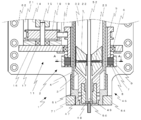
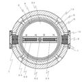
 図1には第一実施形態の攪拌装置を備えた吐出装置の要部断面図、図2には図1の攪拌装置部分を拡大した断面図、図3には図2内のA-A矢視図をそれぞれ示す。また、図4に本実施形態の攪拌装置で用いる攪拌子を示す。図4において(a)は斜視図、(b)は(a)内において矢印Bで示した方向から見た図である。以下では、説明の便宜上、図1のストローク調整機構54側を上側、ノズル50側を下側と呼ぶ場合がある。
 本実施形態の攪拌装置1は、攪拌子保持機構2と、回動機構11と、攪拌子22を主要な構成要素とする。
Below, the form example for implementing this invention is demonstrated.
<< first embodiment >>
(1) Stirrer FIG. 1 is a cross-sectional view of an essential part of a discharge device equipped with the stirrer of the first embodiment, FIG. 2 is an enlarged cross-sectional view of the stirrer part of FIG. 1, and FIG. The AA arrow views are respectively shown. FIG. 4 shows a stirring bar used in the stirring device of the present embodiment. 4A is a perspective view, and FIG. 4B is a diagram viewed from the direction indicated by the arrow B in FIG. In the following, for convenience of explanation, the stroke adjustment mechanism 54 side in FIG. 1 may be referred to as the upper side, and the nozzle 50 side may be referred to as the lower side.
The stirrer 1 of the present embodiment includes the stirrer holding mechanism 2, the rotation mechanism 11, and the stirrer 22 as main components.
(攪拌子保持機構)
 本実施形態に係る撹拌子保持機構2は、容器カバー4と、外筒5と、磁石7を主要な構成要素とする。
 図1および2に示すように、固体粒子混合液体32が充填される容器3は、その外側は円筒状の容器カバー4で覆われている。容器3および容器カバー4は、容器カバー4と同心の外筒5に挿入される。外筒5と容器カバー4との間は一定の隙間が設けられており、外筒5の回転時に互いに擦れないようにされている。外筒5は、回動機構支持部材16に設けられたベアリング6に支持され、外筒5の上部外周に形成された溝に掛けられたベルト19により動力発生機12からの回転力が伝えられて回転する。外筒5の下部に対向して設けられた開口には、一対の磁石7が嵌設されている。
(Stirring bar holding mechanism)
The stirrer holding mechanism 2 according to the present embodiment includes a container cover 4, an outer cylinder 5, and a magnet 7 as main components.
As shown in FIGS. 1 and 2, the outside of the container 3 filled with the solid particle mixed liquid 32 is covered with a cylindrical container cover 4. The container 3 and the container cover 4 are inserted into an outer cylinder 5 concentric with the container cover 4. A constant gap is provided between the outer cylinder 5 and the container cover 4 so that they do not rub against each other when the outer cylinder 5 rotates. The outer cylinder 5 is supported by a bearing 6 provided on the rotation mechanism support member 16, and a rotational force from the power generator 12 is transmitted by a belt 19 that is hung on a groove formed on an upper outer periphery of the outer cylinder 5. Rotate. A pair of magnets 7 is fitted into the opening provided facing the lower portion of the outer cylinder 5.
 図3に示すように、磁石7は、その一方の端面が外筒5の内面と同一面となるように外筒5の開口に嵌設されている。磁石7のほぼ半分は外筒5の周壁に嵌設され、磁石7の残りの部分は外筒5の外側に締結部材10により固定される磁石支持部材8に嵌設されている。磁石7の外側の端面には磁石固定板9が設けられている。磁石固定板9は、締結部材10により着脱自在に固定されているので、磁石7などの部品を簡単に取り付けおよび取り外しすることが可能である。また、磁石支持部材8および磁石固定板9は磁性体でできており、磁石を引きつけるよう作用して磁石が内側へ移動しないようにしている。 As shown in FIG. 3, the magnet 7 is fitted into the opening of the outer cylinder 5 so that one end surface thereof is flush with the inner surface of the outer cylinder 5. Almost half of the magnet 7 is fitted on the peripheral wall of the outer cylinder 5, and the remaining part of the magnet 7 is fitted on a magnet support member 8 fixed to the outside of the outer cylinder 5 by a fastening member 10. A magnet fixing plate 9 is provided on the outer end surface of the magnet 7. Since the magnet fixing plate 9 is detachably fixed by the fastening member 10, parts such as the magnet 7 can be easily attached and detached. The magnet support member 8 and the magnet fixing plate 9 are made of a magnetic material, and act to attract the magnet so that the magnet does not move inward.
 容器3の内部空間は、先細り形状となっている。より詳細には、内部空間の大部分が円柱状であるが、ノズル50と連通する吐出流路71とつながる部分は円錐状となっている。この円錐状の部分には、一対の磁石23を有する攪拌子22が配設される。磁石7は、容器3内に配設された攪拌子22の磁石23に対応する位置に配置される。言い換えると、磁石7と攪拌子22の磁石23とが容器3の中心軸を通る一つの直線上に並ぶように配置される。また、磁石7,23の極性は、図3に「S」と「N」で示すように、磁石7と磁石23とが互いに引き合うよう(引力が作用するよう)な関係となるような配置とする。こうすることで、磁力により攪拌子22を容器3内で吊り下げるような状態で所望の位置に保持することができる。このため、攪拌子22と容器3の底部斜面との間に隙間を空け、互いに接触すること無く攪拌子22を回転させることができる。これにより、前述の課題に挙げたような摩擦による弊害を防ぐことができる。 The inner space of the container 3 is tapered. More specifically, most of the internal space is cylindrical, but the portion connected to the discharge flow path 71 communicating with the nozzle 50 is conical. A stirrer 22 having a pair of magnets 23 is disposed in the conical portion. The magnet 7 is disposed at a position corresponding to the magnet 23 of the stirring bar 22 disposed in the container 3. In other words, the magnet 7 and the magnet 23 of the stirrer 22 are arranged so as to be aligned on one straight line passing through the central axis of the container 3. Further, the polarities of the magnets 7 and 23 are arranged so that the magnet 7 and the magnet 23 are attracted to each other (attractive force acts) as indicated by “S” and “N” in FIG. To do. By doing so, the stirrer 22 can be held at a desired position in a state where it is suspended in the container 3 by magnetic force. For this reason, a clearance gap is made between the stirring bar 22 and the bottom slope of the container 3, and the stirring bar 22 can be rotated without contacting each other. Thereby, it is possible to prevent the adverse effects caused by friction as mentioned in the above-mentioned problem.
 攪拌子22と容器3底部斜面との間の隙間は、例えば、容器3の内径の約1/10~1/5の隙間を空けることが好ましい。これにより、攪拌子22により生起される下側へ向かう流れを混合に利用することができる。本実施形態の攪拌装置1は、側方から磁力を作用させるため、攪拌子22と容器3底部斜面との間の隙間を自由に設定することが可能である。粘度の高い液体を混合しようとする場合には、強磁力の磁石を攪拌子22および外筒5に設ける。 The gap between the stirrer 22 and the bottom slope of the container 3 is preferably, for example, about 1/10 to 1/5 of the inner diameter of the container 3. Thereby, the downward flow generated by the stirrer 22 can be used for mixing. Since the stirrer 1 of this embodiment applies a magnetic force from the side, it is possible to freely set a gap between the stirrer 22 and the bottom slope of the container 3. In order to mix a liquid having a high viscosity, a magnet having a strong magnetic force is provided on the stirrer 22 and the outer cylinder 5.
(回動機構)
 回動機構11について図1および図2を参照しながら説明する。
 本実施形態に係る回動機構11は、回動力発生機12と、動力軸13と、カップリング14と、回転軸15と、プーリ18と、ベルト19を主要な構成要素とする。
 回動力発生機12は、支柱21により回動機構支持部材16に固定されている。回動力発生機12としては、例えば、サーボモータやステッピングモータなどの電動機(モータ)、圧縮空気の作用により回転するエアモータ、超音波の作用により回転する超音波モータなどを用いることができるが、これらに限定されない。ここで、回動力発生機12は、後述の吐出制御装置58とは別の攪拌制御装置20により動作を制御する。
(Rotating mechanism)
The rotation mechanism 11 will be described with reference to FIGS. 1 and 2.
The turning mechanism 11 according to the present embodiment includes a rotating power generator 12, a power shaft 13, a coupling 14, a rotating shaft 15, a pulley 18, and a belt 19 as main components.
The rotating power generator 12 is fixed to the rotating mechanism support member 16 by a support column 21. As the regenerative power generator 12, for example, an electric motor (motor) such as a servo motor or a stepping motor, an air motor rotating by the action of compressed air, an ultrasonic motor rotating by the action of ultrasonic waves, and the like can be used. It is not limited to. Here, the rotating power generator 12 controls the operation by a stirring control device 20 different from a discharge control device 58 described later.
 回動力発生機12で生み出された回転力は、動力軸13を通じて動力軸13とカップリング14で連結された回転軸15へ伝えられる。回転軸15は、回動機構支持部材16に配設されたベアリング17により回転自在に支持されており、伝達された回転力は、回転軸15に固設されたプーリ18を回転させる。プーリ18が回転すると、プーリ18および外筒5の上部に掛けられたベルト19により回転力が外筒5へと伝えられる。そして、外筒5が回転することにより磁石7が回転し、磁力によって容器3の内部の攪拌子22が回転して、容器3内の固体粒子混合液体32の攪拌を実現する。
 上記では、動力を伝達する仕組みについて、ベルト19とプーリ18を用いたものを示したが、チェーンとスプロケットによるものや、歯車によるものなどを用いることができる。
The rotational force generated by the rotational power generator 12 is transmitted to the rotary shaft 15 connected to the power shaft 13 and the coupling 14 through the power shaft 13. The rotating shaft 15 is rotatably supported by a bearing 17 disposed on the rotating mechanism support member 16, and the transmitted rotational force rotates a pulley 18 fixed to the rotating shaft 15. When the pulley 18 rotates, the rotational force is transmitted to the outer cylinder 5 by the belt 19 hung on the pulley 18 and the upper part of the outer cylinder 5. Then, when the outer cylinder 5 rotates, the magnet 7 rotates, and the stirrer 22 inside the container 3 rotates due to the magnetic force, so that the solid particle mixed liquid 32 inside the container 3 is stirred.
In the above description, the mechanism using the belt 19 and the pulley 18 is shown as the mechanism for transmitting the power. However, a mechanism using a chain and a sprocket, a mechanism using a gear, and the like can be used.
(攪拌子)
 攪拌子22は、その上方および下方に循環流を生じさせるような形状とする。上方に循環流を生じさせるためには、例えば、上方に向かって拡径する切り欠き部を上半部に設け、攪拌子が上端に向けて細身になるように回転時に液体に流れを生じさせる作用面(回転軸と容器内周壁と結ぶ線と平行な面であって、上下に延びる最広面)にテーパーを形成する。下方に循環流を生じさせるためには、例えば、容器3の底部斜面と対向する側面を容器3の底部斜面と同様の斜面とし、攪拌子が下端に向けて細身になるように回転時に液体に流れを生じさせる作用面(回転軸と容器内周壁と結ぶ線と平行な面であって、前述の最広面に隣接する上下に延びる面)にテーパーを形成する。以下に説明する本実施形態の攪拌子22は、上方および下方に循環流を生じさせる形状である。以下では、説明の便宜上、容器の内周壁と対向する面およびその対向する面を外側面と呼び、その外側面とほぼ直角に交わる面(回転軸と容器内周壁と結ぶ線と平行な面であって、上下に延びる各面)を正面と呼ぶ。
(Stirring bar)
The stirrer 22 is shaped to generate a circulating flow above and below it. In order to generate a circulating flow upward, for example, a notch that expands upward is provided in the upper half, and the liquid is caused to flow during rotation so that the stirrer is slender toward the upper end. A taper is formed on the working surface (the widest surface extending in the vertical direction and parallel to the line connecting the rotation axis and the inner peripheral wall of the container). In order to generate a circulating flow downward, for example, the side surface facing the bottom slope of the container 3 is set to the same slope as the bottom slope of the container 3, and the liquid is rotated during rotation so that the stirrer is slender toward the lower end. A taper is formed on a working surface (a surface extending parallel to a line connecting the rotation shaft and the inner wall of the container and extending in the vertical direction adjacent to the above-mentioned widest surface). The stirrer 22 of this embodiment described below has a shape that generates a circulating flow upward and downward. Hereinafter, for convenience of explanation, the surface facing the inner peripheral wall of the container and the surface facing the outer peripheral surface are referred to as the outer surface, and a surface that intersects with the outer surface at a substantially right angle (a surface parallel to the line connecting the rotation axis and the inner peripheral wall of the container). Each surface extending vertically) is called a front surface.
 図4(a)に示すように、本実施形態の攪拌子22は回転軸を挟んで二つの翼が設けられた二翼型であり、厚みを持った板状部材に、テーパー面24,25、上切り欠き面27、外側面26、下切り欠き部28、貫通孔30および孔31を設けて形成される。正面からみた攪拌子22は、図1に示すように、矢羽根状である。回転時に液体に流れを生じさせる最も広い平面が上テーパー面24(回転軸を挟んで右半分または左半分が作用面となる)であり、その下方に隣接して設けられた平面が下テーパー面25(回転軸を挟んで右半分または左半分が作用面となる)である。外側面から見た攪拌子22は、急なテーパーが設けられた台形および緩やかなテーパーが設けられた台形の各長辺を外側面26bで接合したような形状となっている。このようなテーパー面24,25を設けたのは、テーパーを設けない場合に比べてより大きな流れを生起できるためである。また、テーパーの傾斜が急な方がより大きな流れを生起しやすいことから、混合する量の多い上テーパー面24を急な傾斜としている。正逆回転のいずれにも対応できるよう、背面にもテーパー面24,25を設け、外側面から見て左右対称な形状とすることが好ましい。 As shown in FIG. 4 (a), the stirrer 22 of this embodiment is a two-blade type in which two blades are provided with a rotating shaft interposed therebetween, and tapered surfaces 24, 25 are formed on a plate-like member having a thickness. The upper cutout surface 27, the outer surface 26, the lower cutout portion 28, the through hole 30 and the hole 31 are provided. As shown in FIG. 1, the stirrer 22 viewed from the front has an arrow blade shape. The widest plane that causes the liquid to flow during rotation is the upper tapered surface 24 (the right half or the left half is the working surface across the rotation axis), and the plane provided adjacent to the lower side is the lower tapered surface 25 (the right half or the left half is the working surface across the rotation axis). The stirrer 22 viewed from the outer side has a shape in which the long sides of the trapezoid having a steep taper and the trapezoid having a gentle taper are joined by the outer side 26b. The reason why such tapered surfaces 24 and 25 are provided is that a larger flow can be generated as compared with the case where no taper is provided. In addition, since a larger flow is more likely to occur when the taper is steep, the upper taper surface 24 having a large amount of mixing is steep. It is preferable to provide tapered surfaces 24 and 25 on the rear surface so that both forward and reverse rotations can be handled, and to have a bilaterally symmetric shape when viewed from the outer surface.
 攪拌子22の下部(外側面26bよりも下の部分)は、容器3の底部形状に合わせて、下方に向かうに従って外側面の幅を狭めてなる外側面26cを形成する。また、攪拌子22の下部の幅方向中央には、下端からほぼ半分の高さ(言い換えると、外側面26bの上端)まで、矩形状の下切り欠き部28を設けている。下切り欠き部28の幅は、貫通孔30の直径と同じかやや大きくする。こうすることで、プランジャ52と下切り欠き部28との間の隙間にも流れを生起させることができる。後述の第二実施形態が備えるストッパ66を設けてもよい。
 一方、攪拌子22の上部(外側面26bよりも上の部分)には、上端から1/4程の位置に、水平面と平行な面である平坦部29を有する。平坦部29の中央には、貫通孔30が設けられている。そして、対向する平坦部29の各端部から外側面方向へ向かって上端まで斜めに、上切り欠き面27がそれぞれ設けられている。このような上部を有する攪拌子22は、容器3の内部により強い上昇流れを生起させることができる。
The lower part of the stirrer 22 (the part below the outer side surface 26 b) forms an outer side surface 26 c that narrows the width of the outer side as it goes downward according to the shape of the bottom of the container 3. In addition, a rectangular lower notch 28 is provided at the center in the width direction of the lower portion of the stirrer 22 from the lower end to almost half the height (in other words, the upper end of the outer surface 26b). The width of the lower notch 28 is the same as or slightly larger than the diameter of the through hole 30. By doing so, a flow can also be generated in the gap between the plunger 52 and the lower notch 28. You may provide the stopper 66 with which 2nd embodiment mentioned later is provided.
On the other hand, the upper portion (the portion above the outer surface 26b) of the stirrer 22 has a flat portion 29 that is a plane parallel to the horizontal plane at a position about 1/4 from the upper end. A through hole 30 is provided in the center of the flat portion 29. And the upper notch surface 27 is each diagonally provided from each edge part of the flat part 29 which opposes to an upper end toward the outer surface direction. The stirrer 22 having such an upper portion can cause a stronger upward flow in the container 3.
 貫通孔30は、後述する吐出装置46のプランジャ52が動作できる程度の直径であり、プランジャ径の約1.5~2倍が好ましい。さらに、外側面26bの少し上の位置に、この貫通孔30に対して直角に、外側面から中心に向かって孔31が一対形成され、それぞれに磁石23が嵌設されている。磁石23の嵌設する孔31は、貫通孔30に達しない深さにする。また、磁石23の長さは、孔31の深さより短くし、孔31の余った部分を封止して固定する。この際、孔31のある外側面26aが平面となるように塞ぐことで、固体粒子が凹みなどに付着して固化することを防ぐことが好ましい。固体粒子混合液体32を攪拌子22の内部に侵入させず、洗浄等のメンテナンス作業を容易にすることができる。 The diameter of the through hole 30 is such that the plunger 52 of the discharge device 46 described later can operate, and is preferably about 1.5 to 2 times the plunger diameter. Further, a pair of holes 31 is formed at a position slightly above the outer surface 26b at a right angle to the through hole 30 from the outer surface toward the center, and a magnet 23 is fitted into each of them. The hole 31 into which the magnet 23 is fitted has a depth that does not reach the through hole 30. The length of the magnet 23 is shorter than the depth of the hole 31, and the remaining part of the hole 31 is sealed and fixed. At this time, it is preferable to prevent the solid particles from adhering to a dent or the like and solidifying by closing the outer surface 26a with the holes 31 so as to be a flat surface. Maintenance work such as cleaning can be facilitated without causing the solid particle mixed liquid 32 to enter the stirrer 22.
(2)容器内の流れ
 本実施形態の攪拌子を実際に回転動作させたときの容器内の流れを図5に模式的に示す。(a)は、攪拌子正面から見たときの容器内の流れの模式図、(b)は攪拌子側面から見たときの容器内の流れの模式図である。なお、図5の模式図は、コンピュータによる流れのシミュレーションの結果に基づいている。
(2) Flow in Container FIG. 5 schematically shows the flow in the container when the stirrer of this embodiment is actually rotated. (A) is a schematic diagram of the flow in the container when viewed from the front of the stirrer, and (b) is a schematic diagram of the flow in the container when viewed from the side of the stirrer. The schematic diagram of FIG. 5 is based on the result of a flow simulation by a computer.
 まず、攪拌子22の上方の流れを説明する。図5(a)に示すように、攪拌子正面から見たとき、攪拌子22の上切り欠き面27上端近傍で生起された上昇流35は、容器3の内周壁を沿って上昇していき、そのまま一気に液面近くまで達する(符号36)。その後、流れ36は、容器3の中心側のプランジャ52近傍で下降流37となり、容器3の中心側を攪拌子22まで流れ下っていく(符号38)。 First, the flow above the stirring bar 22 will be described. As shown in FIG. 5A, the upward flow 35 generated near the upper end of the upper notch surface 27 of the stirrer 22 rises along the inner peripheral wall of the container 3 when viewed from the front of the stirrer. Then, it reaches the liquid level as it is (reference numeral 36). Thereafter, the flow 36 becomes a downward flow 37 in the vicinity of the plunger 52 on the center side of the container 3 and flows down to the stirrer 22 on the center side of the container 3 (reference numeral 38).
 図5(b)に示すように、攪拌子側面から見たとき、攪拌子22の外側面26b近辺(符号39)から生起された上昇流は、容器3の内周壁を沿って上昇していき、液面よりも少し下まで達する(符号40)。この高さは、攪拌子正面から見たときの中心側への流れ(符号37)が見られる高さとほぼ同じ高さである。その後、流れ40は、液面近傍の液体を巻き込みつつ、下降流となり(符号41)、攪拌子22の外側面26bの境界近辺(符号39)まで流れ下っていく。 As shown in FIG. 5 (b), when viewed from the side of the stirrer, the upward flow generated from the vicinity of the outer surface 26 b (reference numeral 39) of the stirrer 22 rises along the inner peripheral wall of the container 3. It reaches a little below the liquid level (reference numeral 40). This height is substantially the same as the height at which the flow toward the center side (reference numeral 37) is seen when viewed from the front of the stirring bar. Thereafter, the flow 40 descends while entraining the liquid in the vicinity of the liquid surface (reference numeral 41), and flows down to the vicinity of the boundary of the outer surface 26b of the stirrer 22 (reference numeral 39).
 以上から、上切り欠き面27および上テーパー面24を有する攪拌子22により、攪拌子22の上方に循環する流れが生起されていることが分かる。この循環する流れにより、攪拌子22の上方にある固体粒子混合液体32を均一に混合することができる。 From the above, it can be seen that the flow that circulates above the stirrer 22 is generated by the stirrer 22 having the upper notch surface 27 and the upper tapered surface 24. By this circulating flow, the solid particle mixed liquid 32 above the stirrer 22 can be uniformly mixed.
 次いで、攪拌子22の下方の流れを説明する。図5(a)に示すように、攪拌子正面から見たとき、下切り欠き部28内には上昇流42が生起されており、吐出流路71内の一部の液体を引っ張るように上昇している(符号43)。これを補うように、攪拌子22と容器3の底部斜面との間に下降流44が生起される。図5(b)に示すように、攪拌子側面から見たとき、攪拌子22の外側面26b近辺で下降流45が生起されている。点線で図示した上昇流42は前述の下切り欠き部28内の流れである。 Next, the flow below the stirring bar 22 will be described. As shown in FIG. 5A, when viewed from the front of the stirrer, an upward flow 42 is generated in the lower notch 28, and the upward flow 42 pulls up some liquid in the discharge flow channel 71. (Reference numeral 43). In order to compensate for this, a downward flow 44 is generated between the stirrer 22 and the bottom slope of the container 3. As shown in FIG. 5 (b), when viewed from the side of the stirrer, a downward flow 45 is generated in the vicinity of the outer surface 26 b of the stirrer 22. The upward flow 42 illustrated by the dotted line is the flow in the lower notch 28 described above.
 以上から、下切り欠き部28および下テーパー面25を有する攪拌子22により、攪拌子22の下方に循環する流れが生起されていることが分かる。また、攪拌子22と容器3の底部斜面との隙間もこの流れに寄与していることが分かる。この循環する流れにより、攪拌子22の下方にある固体粒子混合液体32を均一に混合することができる。
 以上に説明した本実施形態の攪拌子22によれば、攪拌子の上方、下方いずれにも循環する流れを生起することができ、容器内の液体中に分散した固体粒子を均一な混合状態とすることができる。
From the above, it can be seen that the flow that circulates below the stirrer 22 is generated by the stirrer 22 having the lower notch 28 and the lower tapered surface 25. Moreover, it turns out that the clearance gap between the stirring element 22 and the bottom slope of the container 3 also contributes to this flow. By this circulating flow, the solid particle mixed liquid 32 below the stirrer 22 can be uniformly mixed.
According to the stirrer 22 of the present embodiment described above, a flow that circulates both above and below the stirrer can be generated, and the solid particles dispersed in the liquid in the container can be uniformly mixed. can do.
(3)吐出装置
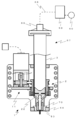
 本実施形態の攪拌装置1は、固体粒子混合液体32を容器3から定量的に吐出、分配する吐出装置46への適用に好適である。特に、プランジャ52の動作により吐出口を開閉することで液体を吐出するプランジャ式吐出装置に適している。図1および図2を参照しながら、本実施形態の攪拌装置1が設けられる吐出装置46の構成および動作を説明する。
(3) Discharge device The stirring device 1 of the present embodiment is suitable for application to the discharge device 46 that quantitatively discharges and distributes the solid particle mixed liquid 32 from the container 3. In particular, it is suitable for a plunger-type discharge device that discharges liquid by opening and closing the discharge port by the operation of the plunger 52. With reference to FIGS. 1 and 2, the configuration and operation of the discharge device 46 provided with the stirring device 1 of the present embodiment will be described.
(構成)
 吐出装置46は、固体粒子混合液体32を貯留する容器(シリンジ)3を備えている。シリンジ3の先端は、吐出流路71の一部を構成する流路を備える接続部材47と嵌合される。接続部材47の吐出流路71の先端となる部分には、バルブシート48および管状のノズル50が配設されている。バルブシート48およびノズル50は、ノズル固定部材51により支持されている。ノズル固定部材51は、シリンジ3を覆う容器カバー4に螺合することにより固定される。バルブシート48は、その中心に連通孔49を有しており、連通孔49によりシリンジ3とノズル50とが連通される。容器3の内部には、攪拌子22の貫通孔30を軸通するプランジャ52が設けられている。プランジャ52はプランジャ駆動機構53により進退動作され、バルブシート48が有する連通孔49を開放および閉鎖する。
 なお、プランジャ52の最進出位置を規定する機構を設け、バルブシートに当接する直前にプランジャを急停止することにより液滴を飛翔吐出するようにしてもよい。
(Constitution)
The discharge device 46 includes a container (syringe) 3 for storing the solid particle mixed liquid 32. The distal end of the syringe 3 is fitted with a connection member 47 having a flow path that forms part of the discharge flow path 71. A valve seat 48 and a tubular nozzle 50 are disposed at the tip of the discharge channel 71 of the connecting member 47. The valve seat 48 and the nozzle 50 are supported by a nozzle fixing member 51. The nozzle fixing member 51 is fixed by screwing into the container cover 4 that covers the syringe 3. The valve seat 48 has a communication hole 49 at the center thereof, and the syringe 3 and the nozzle 50 communicate with each other through the communication hole 49. A plunger 52 that passes through the through hole 30 of the stirrer 22 is provided inside the container 3. The plunger 52 is advanced and retracted by the plunger drive mechanism 53 to open and close the communication hole 49 of the valve seat 48.
In addition, a mechanism for defining the most advanced position of the plunger 52 may be provided, and the droplet may be ejected and ejected by suddenly stopping the plunger immediately before coming into contact with the valve seat.
 プランジャ駆動機構53は、プランジャ52の動作量であるストロークを調節するストローク調整機構54と、調整したストロークを固定するための固定ネジ55を備える。プランジャ駆動機構53は、アダプタ56に接続されており、アダプタ挿入部57をシリンジ3の上部開口端に挿入し、アダプタ56と容器カバー4とを固定することで取り付けられる。プランジャ駆動機構53は、制御配線59により接続される吐出制御装置58により動作を制御される。吐出制御装置58は、圧縮気体源60から供給される圧縮気体を所望の圧力へ調整後、圧縮気体配管61を通じてシリンジ3内へと供給する。 The plunger drive mechanism 53 includes a stroke adjustment mechanism 54 that adjusts a stroke that is an operation amount of the plunger 52, and a fixing screw 55 that fixes the adjusted stroke. The plunger drive mechanism 53 is connected to the adapter 56, and is attached by inserting the adapter insertion portion 57 into the upper opening end of the syringe 3 and fixing the adapter 56 and the container cover 4. The operation of the plunger drive mechanism 53 is controlled by a discharge control device 58 connected by a control wiring 59. The discharge controller 58 adjusts the compressed gas supplied from the compressed gas source 60 to a desired pressure, and then supplies the compressed gas into the syringe 3 through the compressed gas pipe 61.
 吐出装置46は、ベース62に固設された上容器支持部材63および下容器支持部材64によって支持されている。これにより、同じくベース62に固設されている攪拌装置1の外筒5に触れないよう一定の間隔を空けて支持されている。なお、ベース62には、図示しないXYZ駆動機構や固定スタンドなどへ締結部材によって固定するための固定用孔65が複数箇所設けられている。 The discharge device 46 is supported by an upper container support member 63 and a lower container support member 64 fixed to the base 62. As a result, the outer cylinder 5 of the stirrer 1 that is also fixed to the base 62 is supported at a constant interval so as not to touch it. The base 62 is provided with a plurality of fixing holes 65 for fixing to an XYZ drive mechanism or a fixing stand (not shown) with a fastening member.
(動作)
 上記構成の吐出装置46は、次のような動作をする。
 プランジャ52の先端がバルブシート48に当接し、連通孔49を閉鎖している状態を初期状態とする。初期状態で攪拌子22を回転させ、攪拌を開始する。吐出制御装置58より吐出開始信号が発信されると、プランジャ駆動機構53が動作してプランジャ52を上昇させる。このときの上昇距離はストローク調整機構54によって決められている。プランジャ52が上昇してバルブシート48の連通孔49が開放されると、シリンジ3内の固体粒子混合液体32は圧縮気体の作用によりノズル50へと流れ込む。ノズル50へと流れ込んだ固体粒子混合液体32は、ノズル内の流路を通って吐出口から外へと排出される。このとき、固体粒子混合液体32はノズル50先端とつながった状態(糸切りが必要な状態)にある。所定の時間経過後、吐出制御装置58より吐出終了信号が発信されると、プランジャ駆動機構53が動作してプランジャ52を下降させる。プランジャ52が下降してバルブシート48に当接し、連通孔49を閉鎖すると、固体粒子混合液体32は、ノズル50先端から離れて、滴状になって飛翔していく。この間、攪拌子22は一定の速度で回転している。
 以上が一回の吐出に係る基本動作である。複数回吐出を行う場合は、上記基本動作を繰り返す。
(Operation)
The discharge device 46 configured as described above operates as follows.
The state where the tip of the plunger 52 is in contact with the valve seat 48 and the communication hole 49 is closed is the initial state. In the initial state, the stirring bar 22 is rotated and stirring is started. When a discharge start signal is transmitted from the discharge control device 58, the plunger drive mechanism 53 operates to raise the plunger 52. The rising distance at this time is determined by the stroke adjusting mechanism 54. When the plunger 52 rises and the communication hole 49 of the valve seat 48 is opened, the solid particle mixed liquid 32 in the syringe 3 flows into the nozzle 50 by the action of the compressed gas. The solid particle mixed liquid 32 that has flowed into the nozzle 50 passes through the flow path in the nozzle and is discharged out of the discharge port. At this time, the solid particle mixed liquid 32 is in a state of being connected to the tip of the nozzle 50 (a state where thread trimming is necessary). When a discharge end signal is transmitted from the discharge controller 58 after a predetermined time has elapsed, the plunger drive mechanism 53 operates to lower the plunger 52. When the plunger 52 descends and comes into contact with the valve seat 48 and closes the communication hole 49, the solid particle mixed liquid 32 is separated from the tip of the nozzle 50 and flies in droplets. During this time, the stirrer 22 is rotating at a constant speed.
The above is the basic operation related to one discharge. When discharging a plurality of times, the above basic operation is repeated.
《第二実施形態》
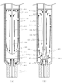
 第二実施形態は、複数個の攪拌子を備える吐出装置に関する。ノズルに連通する容器(シリンジ)の容量が大きい場合や、沈降しやすい粒子を混ぜた液体を用いる場合などに適する構成である。
 本実施形態の攪拌装置1は、シリンジ3の下方から磁力を作用させるのではなく、シリンジ3の側面方向から磁力を作用させるため、シリンジ3の長手方向に複数の撹拌子を配し、これらを回転させることができる。図6に、第二実施形態の攪拌装置を備える吐出装置の要部断面図を示す。以下では、第一実施形態と異なる部分のみ説明し、重複する部分の説明は省略する。
<< Second Embodiment >>
The second embodiment relates to a discharge device including a plurality of stirring bars. This configuration is suitable when the capacity of a container (syringe) communicating with the nozzle is large or when a liquid in which particles that easily settle are mixed is used.
The stirrer 1 of the present embodiment does not act on the magnetic force from below the syringe 3, but acts on the magnetic force from the side surface direction of the syringe 3, so that a plurality of stirrers are arranged in the longitudinal direction of the syringe 3, Can be rotated. In FIG. 6, principal part sectional drawing of a discharge apparatus provided with the stirring apparatus of 2nd embodiment is shown. Below, only a different part from 1st embodiment is demonstrated and description of the overlapping part is abbreviate | omitted.
 本実施形態の攪拌装置1は、3個の攪拌子22を一定の間隔で容器3内に配設する。ここで、攪拌子22を複数個設ける場合、それらに対応する磁石7およびこれを固定する部材も複数個設けなければならない。そこで、本実施形態では、3個の攪拌子22に対応する位置までを覆う長さであり、磁石7、磁石支持部材8および磁石固定板9を3組設けた外筒5を用いている。それに伴い、回動機構11も、第一実施形態と比べ上方に位置させる。 The stirring device 1 of the present embodiment has three stirring bars 22 arranged in the container 3 at regular intervals. Here, when a plurality of stirrers 22 are provided, a plurality of magnets 7 corresponding thereto and members for fixing the magnets 7 must be provided. Therefore, in the present embodiment, the outer cylinder 5 having a length that covers up to the position corresponding to the three stirring bars 22 and provided with three sets of the magnet 7, the magnet support member 8, and the magnet fixing plate 9 is used. Accordingly, the rotation mechanism 11 is also positioned above the first embodiment.
 外筒5を支持するベアリング6は、攪拌子保持機構2側の1箇所に設けるのでもよいが、図6に示すように、2箇所とすることでより安定して回転させることができる。容器3の内部では、攪拌子22同士がくっついてしまわないよう、プランジャ52に一定間隔でストッパ66を設けてもよい。このストッパ66は回転しないようプランジャ52に固定されている。ストッパ66上端と攪拌子22との間は、予定しているストローク分以上の隙間を空けておくことで、吐出動作の妨げとなることを防ぐ。攪拌子22同士の間隔は、例えば、容器3の内径の約0.5~1.5倍が好ましい。そうすることで、攪拌子22の上方および下方に流れを生起させ、均一に混合することができる。本構成例の各攪拌子22は、同心に整列させた状態(上面から見るとぴったりと重なる状態)で配置されているが、一定角度(例えば60度)ずつずらして配置してもよい。 The bearing 6 that supports the outer cylinder 5 may be provided at one place on the side of the stirrer holding mechanism 2, but can be rotated more stably by using two places as shown in FIG. 6. Inside the container 3, stoppers 66 may be provided on the plunger 52 at regular intervals so that the stirring bars 22 do not stick together. This stopper 66 is fixed to the plunger 52 so as not to rotate. The gap between the upper end of the stopper 66 and the stirrer 22 is not less than the planned stroke, thereby preventing the discharge operation from being hindered. The distance between the stirrers 22 is preferably about 0.5 to 1.5 times the inner diameter of the container 3, for example. By doing so, a flow can be generated above and below the stirrer 22 and mixed uniformly. The stirrers 22 of this configuration example are arranged in a concentric state (a state where they are exactly overlapped when viewed from above), but may be arranged by being shifted by a certain angle (for example, 60 degrees).
 以上に説明した本実施形態の吐出装置46によれば、ノズルに連通する容器(シリンジ)の容量が大きい場合や、沈降しやすい粒子を混ぜた液体を用いる場合でも、固体粒子を液体中に均一に混合しながら吐出作業を行うことができる。 According to the discharge device 46 of the present embodiment described above, even when the capacity of the container (syringe) communicating with the nozzle is large or when using a liquid in which particles that easily settle are used, the solid particles are uniformly contained in the liquid. The discharging operation can be performed while mixing.
《第三実施形態》
 第三実施形態は、圧縮気体の作用により容器(シリンジ)3内の液体を吐出するエア式吐出装置に関する。図7に、第三実施形態の攪拌装置を備える吐出装置の要部断面図を示す。以下では、第一実施形態と異なる部分のみ説明し、重複する部分の説明は省略する。
<< Third embodiment >>
The third embodiment relates to an air-type discharge device that discharges liquid in a container (syringe) 3 by the action of compressed gas. In FIG. 7, the principal part sectional drawing of a discharge device provided with the stirring apparatus of 3rd embodiment is shown. Below, only a different part from 1st embodiment is demonstrated and description of the overlapping part is abbreviate | omitted.
 本実施形態の吐出装置67は、プランジャ52とそれに関係する構成は無く、容器3と、ノズル50と、圧縮気体源60から供給される圧縮気体を所望の圧力へ調整して供給する吐出制御装置58と、容器3に調圧された圧縮気体をチューブ68を介して供給するアダプタ69と、を主要な構成要素とする。吐出装置67は、調圧された圧縮気体を所定時間容器内の液体に印加することで液体を吐出する。
吐出装置67は、下容器支持部材64に設けられたノズルガイド70に支持される。攪拌子22は、プランジャ52が無いために、貫通孔30を設けなくてもよいが、貫通孔30を通過する流れを生じさせるために設けてもよい。
The discharge device 67 according to the present embodiment has no plunger 52 and a configuration related thereto, and is a discharge control device that adjusts and supplies the compressed gas supplied from the container 3, the nozzle 50, and the compressed gas source 60 to a desired pressure. 58 and an adapter 69 that supplies the compressed gas regulated in the container 3 through the tube 68 are main components. The discharge device 67 discharges the liquid by applying the regulated compressed gas to the liquid in the container for a predetermined time.
The discharge device 67 is supported by a nozzle guide 70 provided on the lower container support member 64. The stirrer 22 may not be provided with the through hole 30 because there is no plunger 52, but may be provided to generate a flow that passes through the through hole 30.
 以上に説明した本実施形態の吐出装置67によれば、固体粒子を液体中に均一に混合しながら、プランジャでの吐出に適しない液体材料の吐出作業を行うことも可能である。 According to the discharge device 67 of the present embodiment described above, it is possible to perform a discharge operation of a liquid material that is not suitable for discharge with a plunger while uniformly mixing solid particles in the liquid.
《第四実施形態》
 第四実施形態は、四翼型の攪拌子を備える吐出装置に関する。図8に、第四実施形態の攪拌装置に係る攪拌子を説明する斜視図を示す。以下では、第一実施形態と異なる部分のみ説明し、重複する部分の説明は省略する。
<< 4th embodiment >>
The fourth embodiment relates to a discharge device including a four-blade stirrer. In FIG. 8, the perspective view explaining the stirring element which concerns on the stirring apparatus of 4th embodiment is shown. Below, only a different part from 1st embodiment is demonstrated and description of the overlapping part is abbreviate | omitted.
 図8に示すように、攪拌子72は、貫通孔30を中心として対向する四枚の翼を有しており、上面視十字形となっている。第一実施形態の二翼型の攪拌子22と同様に、各翼にテーパー面24,25、上切り欠き面27、外側面26、下切り欠き部28、貫通孔30、平坦部29および孔31を設けている。
 この攪拌子72により生起される流れは、攪拌子22により生起される流れ(図5)と基本的傾向に違いはないが、流れが生起される箇所が2箇所ずつから4箇所ずつに増え、より分割された細かな流れとすることができ、容器内の液体中に分散した固体粒子を均一な混合状態とすることができる。
 本実施形態では、孔31および磁石23を一対としているが、攪拌子自体の重さや液体の粘度などにより大きな力が必要なときは、孔31および磁石23を二対としてもよい。
 なお、本実施形態では、四翼型の攪拌子を開示したが、用途に応じて三翼型の攪拌子を用いてもよい。
As shown in FIG. 8, the stirrer 72 has four blades facing each other with the through hole 30 as a center, and has a cross shape when viewed from above. Similar to the two-blade stirrer 22 of the first embodiment, each blade has a tapered surface 24, 25, an upper notch surface 27, an outer surface 26, a lower notch portion 28, a through hole 30, a flat portion 29, and a hole. 31 is provided.
The flow generated by the stirrer 72 is not different in basic tendency from the flow generated by the stirrer 22 (FIG. 5), but the number of points where the flow is generated increases from two to four. The flow can be further divided into fine flows, and the solid particles dispersed in the liquid in the container can be uniformly mixed.
In the present embodiment, the hole 31 and the magnet 23 are paired. However, when a large force is required due to the weight of the stirring bar itself, the viscosity of the liquid, or the like, the hole 31 and the magnet 23 may be paired.
In the present embodiment, a four-blade stirrer is disclosed, but a three-blade stirrer may be used depending on the application.
 本発明は、例えば、次のような用途に用いられる。
・乾式潤滑剤(固体潤滑剤)の膜を形成するための塗布
・LEDモジュールの蛍光体層などを形成するための塗布
The present invention is used for the following applications, for example.
・ Application to form a film of dry lubricant (solid lubricant) ・ Application to form a phosphor layer of an LED module
1:攪拌装置 2:攪拌子保持機構 3:容器(シリンジ) 4:容器カバー 5:外筒 6:ベアリング(外筒用) 7:磁石(外筒用) 8:磁石支持部材 9:磁石固定板 10:締結部材(外筒用) 11:回動機構 12:回動力発生機 13:動力軸 14:カップリング 15:回転軸 16:回動機構支持部材 17:ベアリング(回転軸用) 18:プーリ 19:ベルト 20:攪拌制御装置 21:支柱 22:攪拌子 23:磁石(攪拌子用) 24:上テーパー面 25:下テーパー面 26:外側面 27:上切り欠き面 28:下切り欠き部 29:平坦部 30:貫通孔 31:孔 32:固体粒子混合液体 33~45:流れ 46:吐出装置 47:接続部材 48:バルブシート 49:連通孔 50:ノズル 51:ノズル固定部材 52:プランジャ 53:プランジャ駆動機構 54:ストローク調整機構 55:固定ネジ 56:アダプタ 57:アダプタ挿入部 58:吐出制御装置 59:制御配線 60:圧縮気体源 61:圧縮気体配管 62:ベース 63:上容器支持部材 64:下容器支持部材 65:固定用孔 66:ストッパ 67:エア式吐出装置 68:チューブ 69:アダプタ(エア式) 70:ノズルガイド 71:吐出流路 72:攪拌子 S:磁石のS極 N:磁石のN極 1: Stirrer 2: Stirrer holding mechanism 3: Container (syringe) 4: Container cover 5: Outer cylinder 6: Bearing (for outer cylinder) 7: Magnet (for outer cylinder) 8: Magnet support member 9: Magnet fixing plate 10: fastening member (for outer cylinder) 11: rotating mechanism 12: rotating power generator 13: power shaft 14: coupling 15: rotating shaft 16: rotating mechanism supporting member 17: bearing (for rotating shaft) 18: pulley 19: belt 20: stirring control device 21: support 22: stirring bar 23: magnet (for stirring bar) 24: upper taper surface 25: lower taper surface 26: outer surface 27: upper notch surface 28: lower notch 29 : Flat part 30: Through hole 31: Hole 32: Solid particle mixed liquid 33-45: Flow 46: Discharge device 47: Connection member 48: Valve seat 49: Communication hole 5 : Nozzle 51: Nozzle fixing member 52: Plunger 53: Plunger drive mechanism 54: Stroke adjustment mechanism 55: Fixing screw 56: Adapter 57: Adapter insertion part 58: Discharge control device 59: Control wiring 60: Compressed gas source 61: Compressed gas Piping 62: Base 63: Upper container support member 64: Lower container support member 65: Fixing hole 66: Stopper 67: Air discharge device 68: Tube 69: Adapter (air type) 70: Nozzle guide 71: Discharge flow path 72 : Stirrer S: S pole of magnet N: N pole of magnet

Claims (13)

  1.  磁石を有する攪拌子と、
     攪拌子に側方から磁力を作用させることにより、攪拌子を位置規定する攪拌子保持機構と、
     攪拌子保持機構を回転させる回動機構と、
    を備え、
     前記回動機構により攪拌子保持機構を回転させることにより、攪拌子を回転させることを特徴とする攪拌装置。
    A stir bar having a magnet;
    A stirrer holding mechanism that positions the stirrer by applying a magnetic force to the stirrer from the side;
    A rotating mechanism for rotating the stirring bar holding mechanism;
    With
    A stirrer that rotates a stirrer by rotating a stirrer holding mechanism by the rotating mechanism.
  2.  前記攪拌子は、回転時に液体に流れを生じさせる最も広い第1作用面を有する翼を備え、第1作用面に、上端に向けて細身になるようにテーパーを形成したことを特徴とする請求項1記載の攪拌装置。 The stirrer includes a blade having a widest first working surface that causes a liquid to flow when rotating, and the first working surface is tapered so as to become narrower toward an upper end. Item 2. The stirring device according to Item 1.
  3.  前記攪拌子の翼は、第1作用面に隣接し、回転時に液体に流れを生じさせる第2作用面を有し、第2作用面に、下端に向けて細身になるようにテーパーを形成したことを特徴とする請求項2記載の攪拌装置。 The blade of the stirrer is adjacent to the first working surface, has a second working surface that causes a liquid to flow during rotation, and the second working surface is tapered so as to become narrower toward the lower end. The stirring device according to claim 2.
  4.  前記攪拌子が、その上半部に向かって拡径する切り欠き部を有することを特徴とする請求項2または3記載の攪拌装置。 The stirrer according to claim 2 or 3, wherein the stirrer has a notch that expands toward the upper half.
  5.  前記攪拌子が、その下半部に切り欠き部を有することを特徴とする請求項1ないし4のいずれかに記載の攪拌装置。 The stirrer according to any one of claims 1 to 4, wherein the stirrer has a notch in its lower half.
  6.  前記攪拌子が、前記切り欠き部と連通する回転軸と同心の貫通孔を有することを特徴とする請求項5に記載の攪拌装置。 The stirring device according to claim 5, wherein the stirring bar has a through hole concentric with a rotating shaft communicating with the notch.
  7.  前記攪拌子が、二翼型であることを特徴とする請求項1ないし5のいずれかに記載の攪拌装置。 The stirrer according to any one of claims 1 to 5, wherein the stirrer is of a two-blade type.
  8.  前記攪拌子が、四翼型であることを特徴とする請求項1ないし5のいずれかに記載の攪拌装置。 The stirrer according to any one of claims 1 to 5, wherein the stirrer is a four-wing type.
  9.  請求項1ないし8のいずれかに記載の攪拌装置と、
     前記攪拌子保持機構が装着される液体貯留容器と、
     液体貯留容器と連通するノズルと、
     圧縮気体源と、
     圧縮気体源から供給される圧縮気体を所望の圧力へ調整して供給する吐出制御装置と、
    を備える吐出装置。
    A stirrer according to any one of claims 1 to 8,
    A liquid storage container to which the stirring bar holding mechanism is attached;
    A nozzle in communication with the liquid storage container;
    A compressed gas source;
    A discharge control device that adjusts and supplies the compressed gas supplied from the compressed gas source to a desired pressure;
    A discharge device comprising:
  10.  請求項6に記載の攪拌装置と、
     前記攪拌子保持機構が装着される液体貯留容器と、
     液体貯留容器と連通するノズルと、
     液体貯留容器内に配置されたプランジャと、
     プランジャを往復動させるプランジャ駆動機構と、
    を備える吐出装置。
    A stirring device according to claim 6;
    A liquid storage container to which the stirring bar holding mechanism is attached;
    A nozzle in communication with the liquid storage container;
    A plunger disposed in the liquid storage container;
    A plunger drive mechanism for reciprocating the plunger;
    A discharge device comprising:
  11.  前記液体貯留容器の内部空間が、下端に向けて先細り形状であり、
     前記攪拌子の外側面が、前記液体貯留容器の底部内壁と一定の隙間ができる先細り形状であることを特徴とする請求項9または10記載の吐出装置。
    The internal space of the liquid storage container is tapered toward the lower end,
    The ejection device according to claim 9 or 10, wherein the outer surface of the stirrer has a tapered shape that forms a certain gap with the inner wall of the bottom of the liquid storage container.
  12.  前記攪拌子が、複数の攪拌子からなり、
     前記攪拌子保持機構が、複数の攪拌子を位置規定することを特徴とする請求項9ないし11のいずれかに記載の吐出装置。
    The stirrer comprises a plurality of stirrers,
    The discharge device according to claim 9, wherein the stirring bar holding mechanism positions a plurality of stirring bars.
  13.  請求項9ないし12のいずれかに記載の吐出装置を用い、前記攪拌子を一定速度で回転させながら、液体をノズルから吐出することを特徴とする吐出方法。 A discharge method using the discharge device according to any one of claims 9 to 12, wherein the liquid is discharged from a nozzle while rotating the stirring bar at a constant speed.
PCT/JP2013/052455 2012-02-07 2013-02-04 Mixing device, discharge device provided therewith, and discharge method WO2013118673A1 (en)

Priority Applications (6)

Application Number Priority Date Filing Date Title
US14/376,735 US10315173B2 (en) 2012-02-07 2013-02-04 Mixing device, discharge device provided therewith, and discharge method
CN201380008448.1A CN104168992B (en) 2012-02-07 2013-02-04 Agitating device and possess its device for discharging fixed and discharge method
EP13746864.1A EP2813282B1 (en) 2012-02-07 2013-02-04 Mixing device, discharge device provided therewith, and discharge method
SG11201404617SA SG11201404617SA (en) 2012-02-07 2013-02-04 Mixing device, discharge device provided therewith, and discharge method
KR1020147024930A KR102043769B1 (en) 2012-02-07 2013-02-04 Mixing device, discharge device provided therewith, and discharge method
HK15100951.0A HK1200396A1 (en) 2012-02-07 2015-01-28 Mixing device, discharge device provided therewith, and discharge method

Applications Claiming Priority (2)

Application Number Priority Date Filing Date Title
JP2012024165A JP5792652B2 (en) 2012-02-07 2012-02-07 Stirring device, discharge device including the same, and discharge method
JP2012-024165 2012-02-07

Publications (1)

Publication Number Publication Date
WO2013118673A1 true WO2013118673A1 (en) 2013-08-15

Family

ID=48947437

Family Applications (1)

Application Number Title Priority Date Filing Date
PCT/JP2013/052455 WO2013118673A1 (en) 2012-02-07 2013-02-04 Mixing device, discharge device provided therewith, and discharge method

Country Status (10)

Country Link
US (1) US10315173B2 (en)
EP (1) EP2813282B1 (en)
JP (1) JP5792652B2 (en)
KR (1) KR102043769B1 (en)
CN (1) CN104168992B (en)
HK (1) HK1200396A1 (en)
MY (1) MY167973A (en)
SG (2) SG10201604887RA (en)
TW (1) TWI574738B (en)
WO (1) WO2013118673A1 (en)

Cited By (1)

* Cited by examiner, † Cited by third party
Publication number Priority date Publication date Assignee Title
CN107597461A (en) * 2017-09-30 2018-01-19 厦门大学 A kind of magnetic agitation mini sprinkler and micro-nano direct write platform

Families Citing this family (12)

* Cited by examiner, † Cited by third party
Publication number Priority date Publication date Assignee Title
GB201303806D0 (en) * 2013-03-04 2013-04-17 3P Innovation Ltd A mixing apparatus
US9101893B1 (en) * 2014-03-17 2015-08-11 Advanced Scientifics, Inc. Mixing assembly and mixing method
JP6452147B2 (en) * 2015-01-19 2019-01-16 武蔵エンジニアリング株式会社 Liquid material discharge device
JP6778426B2 (en) * 2016-09-20 2020-11-04 武蔵エンジニアリング株式会社 Liquid material discharge device
CN109364776A (en) * 2018-10-23 2019-02-22 常州机电职业技术学院 Powder-liquid mixing machine
USD934929S1 (en) * 2020-09-18 2021-11-02 Elliot Kremerman Housing for spindles and rotary belt
USD934930S1 (en) * 2021-08-02 2021-11-02 Elliot Kremerman Spinner
USD935497S1 (en) * 2021-08-02 2021-11-09 Elliot Kremerman Spinner
USD934316S1 (en) * 2021-08-02 2021-10-26 Elliot Kremerman Spinner
USD935496S1 (en) * 2021-08-02 2021-11-09 Elliot Kremerman Spinner
CN113750856B (en) * 2021-09-09 2024-03-26 澳昌(武汉)生态科技有限公司 Quantitative discharging device for building coating production
CN114669208A (en) * 2022-03-18 2022-06-28 上海易励机械设备有限公司 Lubricating oil production equipment

Citations (8)

* Cited by examiner, † Cited by third party
Publication number Priority date Publication date Assignee Title
JPS60140638U (en) * 1984-02-28 1985-09-18 株式会社東芝 stirring device
JPS62221427A (en) * 1986-03-24 1987-09-29 Seiko Instr & Electronics Ltd Liquid flowing and stirring device
WO2001094027A2 (en) * 2000-06-05 2001-12-13 Nordson Corporation Apparatus and methods for dispensing minute amounts of liquid
US20020041537A1 (en) * 2000-10-10 2002-04-11 Yale Jeffrey Lane Stirring element and associated metering gun
JP2003144891A (en) 2001-11-19 2003-05-20 Maguneo Giken:Kk Magnetic drive unit, agitating apparatus, mixing apparatus and substrate processing apparatus
US6758593B1 (en) * 2000-10-09 2004-07-06 Levtech, Inc. Pumping or mixing system using a levitating magnetic element, related system components, and related methods
JP2005120956A (en) 2003-10-17 2005-05-12 Fujisawa Pharmaceut Co Ltd Discharge device
WO2011152781A1 (en) * 2010-05-31 2011-12-08 Ge Healthcare Bio-Sciences Ab Adjustable volume mixer chamber and method of use

Family Cites Families (6)

* Cited by examiner, † Cited by third party
Publication number Priority date Publication date Assignee Title
US2495895A (en) 1945-10-31 1950-01-31 Universal Oil Prod Co Fluid circulating device
JPS4527958Y1 (en) 1966-04-18 1970-10-28
KR100455952B1 (en) * 1998-03-31 2004-11-06 스미도모쥬기가이고교 가부시키가이샤 Vertical agitating apparatus
JP3632827B2 (en) * 1998-11-11 2005-03-23 リンテック株式会社 Stirrer
US20030185096A1 (en) * 2002-11-26 2003-10-02 Hollstein Thomas E. Apparatus and methods for dispensing minute amounts of liquid
CN102230749B (en) * 2011-07-01 2012-11-07 山东华特磁电科技股份有限公司 Aluminum solution stirring device of air-cooled composite magnetic field

Patent Citations (8)

* Cited by examiner, † Cited by third party
Publication number Priority date Publication date Assignee Title
JPS60140638U (en) * 1984-02-28 1985-09-18 株式会社東芝 stirring device
JPS62221427A (en) * 1986-03-24 1987-09-29 Seiko Instr & Electronics Ltd Liquid flowing and stirring device
WO2001094027A2 (en) * 2000-06-05 2001-12-13 Nordson Corporation Apparatus and methods for dispensing minute amounts of liquid
US6758593B1 (en) * 2000-10-09 2004-07-06 Levtech, Inc. Pumping or mixing system using a levitating magnetic element, related system components, and related methods
US20020041537A1 (en) * 2000-10-10 2002-04-11 Yale Jeffrey Lane Stirring element and associated metering gun
JP2003144891A (en) 2001-11-19 2003-05-20 Maguneo Giken:Kk Magnetic drive unit, agitating apparatus, mixing apparatus and substrate processing apparatus
JP2005120956A (en) 2003-10-17 2005-05-12 Fujisawa Pharmaceut Co Ltd Discharge device
WO2011152781A1 (en) * 2010-05-31 2011-12-08 Ge Healthcare Bio-Sciences Ab Adjustable volume mixer chamber and method of use

Non-Patent Citations (1)

* Cited by examiner, † Cited by third party
Title
See also references of EP2813282A4

Cited By (1)

* Cited by examiner, † Cited by third party
Publication number Priority date Publication date Assignee Title
CN107597461A (en) * 2017-09-30 2018-01-19 厦门大学 A kind of magnetic agitation mini sprinkler and micro-nano direct write platform

Also Published As

Publication number Publication date
KR102043769B1 (en) 2019-11-12
TW201343259A (en) 2013-11-01
MY167973A (en) 2018-10-09
EP2813282A1 (en) 2014-12-17
EP2813282B1 (en) 2018-06-20
SG11201404617SA (en) 2014-10-30
JP2013158733A (en) 2013-08-19
SG10201604887RA (en) 2016-08-30
TWI574738B (en) 2017-03-21
KR20140122752A (en) 2014-10-20
EP2813282A4 (en) 2015-10-14
CN104168992B (en) 2016-08-17
US20140376328A1 (en) 2014-12-25
JP5792652B2 (en) 2015-10-14
CN104168992A (en) 2014-11-26
HK1200396A1 (en) 2015-08-07
US10315173B2 (en) 2019-06-11

Similar Documents

Publication Publication Date Title
JP5792652B2 (en) Stirring device, discharge device including the same, and discharge method
US10086344B2 (en) Tank apparatus, a system for dispersing by circulating a mixture, and a method for dispersing by circulating a mixture
US7748893B2 (en) Magnetic stirring arrangement
JP2007136302A (en) Kneader and kneading method
KR20170137288A (en) Robot Dispenser
CN110559906A (en) Mixing arrangement of nanometer coating material with unloading of being convenient for
CN112108055A (en) Solid-liquid raw material mixing and proportioning device capable of achieving automatic proportioning for chemical production
KR20110058794A (en) Material filling device and material filling method
CN209809962U (en) Liquid raw material mixing equipment for chemical industry
CN215842791U (en) High-viscosity material charging device
JP6928962B2 (en) Liquid discharge device, coating device equipped with the same discharge device, and its coating method
JP5302265B2 (en) Rotating body for stirring and stirring device
JP2022107704A (en) Stirring blade and stirring device
JP3217272B2 (en) Kneading device
CN217857022U (en) Colloid output device
JP2018008240A (en) Liquid emulsification apparatus
JP2016195991A (en) Three-dimensional autorotation and revolution type agitator
JP5385480B2 (en) Rotating body for stirring and stirring device
CN211435820U (en) Mixing arrangement of nanometer coating material with unloading of being convenient for
CN109833811A (en) A kind of blender of adjustable revolving speed
CN216024434U (en) High-speed dispersion machine is used in acrylic resin production
CN203108496U (en) Stirring device and cylinder type stirring paddle thereof
CN217313140U (en) Ultrasonic homogenizer
CN214106712U (en) Automatic material mixing device for cutter coating processing
CN111888966B (en) Homogenizing device for medicine

Legal Events

Date Code Title Description
121 Ep: the epo has been informed by wipo that ep was designated in this application

Ref document number: 13746864

Country of ref document: EP

Kind code of ref document: A1

DPE1 Request for preliminary examination filed after expiration of 19th month from priority date (pct application filed from 20040101)
WWE Wipo information: entry into national phase

Ref document number: 14376735

Country of ref document: US

NENP Non-entry into the national phase

Ref country code: DE

WWE Wipo information: entry into national phase

Ref document number: 2013746864

Country of ref document: EP

ENP Entry into the national phase

Ref document number: 20147024930

Country of ref document: KR

Kind code of ref document: A