WO2013145659A1 - Object information acquiring apparatus - Google Patents
Object information acquiring apparatus Download PDFInfo
- Publication number
- WO2013145659A1 WO2013145659A1 PCT/JP2013/001931 JP2013001931W WO2013145659A1 WO 2013145659 A1 WO2013145659 A1 WO 2013145659A1 JP 2013001931 W JP2013001931 W JP 2013001931W WO 2013145659 A1 WO2013145659 A1 WO 2013145659A1
- Authority
- WO
- WIPO (PCT)
- Prior art keywords
- light
- light source
- unit
- signal
- photoacoustic
- Prior art date
Links
Images


Classifications
-
- A—HUMAN NECESSITIES
- A61—MEDICAL OR VETERINARY SCIENCE; HYGIENE
- A61B—DIAGNOSIS; SURGERY; IDENTIFICATION
- A61B5/00—Measuring for diagnostic purposes; Identification of persons
- A61B5/0093—Detecting, measuring or recording by applying one single type of energy and measuring its conversion into another type of energy
- A61B5/0095—Detecting, measuring or recording by applying one single type of energy and measuring its conversion into another type of energy by applying light and detecting acoustic waves, i.e. photoacoustic measurements
-
- A—HUMAN NECESSITIES
- A61—MEDICAL OR VETERINARY SCIENCE; HYGIENE
- A61B—DIAGNOSIS; SURGERY; IDENTIFICATION
- A61B5/00—Measuring for diagnostic purposes; Identification of persons
- A61B5/145—Measuring characteristics of blood in vivo, e.g. gas concentration, pH value; Measuring characteristics of body fluids or tissues, e.g. interstitial fluid, cerebral tissue
- A61B5/14542—Measuring characteristics of blood in vivo, e.g. gas concentration, pH value; Measuring characteristics of body fluids or tissues, e.g. interstitial fluid, cerebral tissue for measuring blood gases
-
- G—PHYSICS
- G01—MEASURING; TESTING
- G01N—INVESTIGATING OR ANALYSING MATERIALS BY DETERMINING THEIR CHEMICAL OR PHYSICAL PROPERTIES
- G01N21/00—Investigating or analysing materials by the use of optical means, i.e. using sub-millimetre waves, infrared, visible or ultraviolet light
- G01N21/17—Systems in which incident light is modified in accordance with the properties of the material investigated
- G01N21/1702—Systems in which incident light is modified in accordance with the properties of the material investigated with opto-acoustic detection, e.g. for gases or analysing solids
-
- A—HUMAN NECESSITIES
- A61—MEDICAL OR VETERINARY SCIENCE; HYGIENE
- A61B—DIAGNOSIS; SURGERY; IDENTIFICATION
- A61B2562/00—Details of sensors; Constructional details of sensor housings or probes; Accessories for sensors
- A61B2562/18—Shielding or protection of sensors from environmental influences, e.g. protection from mechanical damage
- A61B2562/182—Electrical shielding, e.g. using a Faraday cage
Definitions
- the present invention relates to an object information acquiring apparatus.
- a controller inside the apparatus upon receiving an instruction from the user, sends a signal to the drive circuit of a light source to emit light pulses.
- a controller inside the apparatus sends a signal to the drive circuit of a light source to emit light pulses.
- the object When an object is irradiated with laser pulses via a light guide, the object generates photoacoustic waves.
- the photoacoustic waves are received by a probe that is in contact with the object, and converted to an electrical signal called a photoacoustic signal.
- the controller performs signal processing and image reconstruction to this photoacoustic signal and presents an image for diagnosis to the user.
- Patent Literature 1 a photoacoustic apparatus including an optical sensor for detecting the emission timing of light pulses.
- PTL 1 Patent Literature 1
- part of light delivered in pulses is guided to the optical sensor to detect the emission timing.
- a receiving circuit controls when to start and stop receiving the photoacoustic signal in synchronism with the emission timing detected by the optical sensor.
- the position of a light absorbing segment inside the object is estimated based on a time difference between the emission timing and the received signal, to reconstruct an image.
- the light source When high power laser such as the one mentioned above is used as the light source, generally, the light source, the light guide, and the optical sensor are accommodated in one housing so that no light pulse leaks to the outside of the housing, for securing safety of the apparatus.
- An optical component such as a beam splitter or mirror is used as the light guide, to branch and guide the pulsed light beam to the optical sensor.
- the optical sensor when driving the light source, electromagnetic noise from the drive circuit of the high voltage, high current light source sometimes diffracts to the optical sensor. This may result in malfunctioning of the optical sensor, which adversely affects the synchronization of the emission timing and the photoacoustic wave reception, because of which the image reflecting the condition inside the object may not be generated correctly.
- the optical sensor could be covered by a shield member or the like to block the noise.
- the influence of electromagnetic noise can be reduced only to a limited extent because of the high intensity of electromagnetic noise from the light source and of the difficulties in providing electromagnetic shields to apertures and connector parts.
- the present invention was made in view of the above problem and its object is to reduce the influence of electromagnetic noise from a light source on an optical sensor during photoacoustic measurements.
- the present invention provides an object information acquiring apparatus, comprising: a light source unit including a light source and a drive circuit driving the light source; a probe configured to convert an acoustic wave generated from an object irradiated with light emitted from the light source into an electrical signal; a light detector configured to detect the light emitted from the light source and generate a trigger signal; a controller configured to receive the trigger signal from the light detector and the electrical signal from the probe, and generate property information from the inside of the object; and a housing configured to implemente shielding of electromagnetic noise generated from the light source unit, wherein the housing accommodates the light detector so as to separate the light detector from the light source unit.
- FIG. 1 is a block diagram of Embodiment 1 of the present invention
- FIG. 2 is an operation flowchart of Embodiment 1 of the present invention
- FIG. 3 is a diagram illustrating the internal structure of a controller in Embodiment 1 of the present invention
- FIG. 4 is a configuration diagram of a fiber bundle in Embodiment 1 of the present invention
- FIG. 5 is a block diagram of Embodiment 2 of the present invention
- FIG. 6 is a configuration diagram of a probe in Embodiment 2 of the present invention
- FIG. 7 is a timing diagram of Embodiment 1 of the present invention.
- the photoacoustic apparatus of the present invention is an apparatus for obtaining property information on the inside of an object as image data by utilizing the photoacoustic effect, wherein light (electromagnetic wave) is projected to the object and an acoustic wave thereby generated inside the object is received.
- the property information thus acquired includes source distributions of acoustic waves generated by the irradiation with light, initial sound pressure distributions inside the object, or, light energy absorption density distributions, absorption coefficient distributions, or density distributions of tissue-forming substances, which are deduced from the initial sound pressure distributions.
- the density distribution of substance may be, for example, an oxygen saturation distribution, or a density distribution of oxidized hemoglobin or reduced hemoglobin.
- the photoacoustic apparatus of the present invention can also be called an object information acquiring apparatus.
- the acoustic waves when referred to in the present invention, are typically ultrasound waves, and include elastic waves that are called sound waves, ultrasound waves, or acoustic waves.
- An acoustic wave generated by the photoacoustic effect is referred to as a "photoacoustic wave", or a "light-induced ultrasound wave”.
- a probe of the object information acquiring apparatus receives the acoustic waves generated inside an object.
- FIG. 1 is a block diagram illustrating a photoacoustic apparatus according to this embodiment.
- reference numeral 101 denotes a holding unit that retains an object, projects light pulses to the object, receives a photoacoustic wave from the object, and converts it into a photoacoustic signal.
- Reference numeral 102 denotes a light source unit including a light source, a drive circuit for the light source, and an optical system.
- Reference numeral 103 denotes a controller that receives the photoacoustic signal, performs signal processing and image processing, presents a diagnostic image to the user, and controls the overall operation of the apparatus.
- Reference numeral 104 denotes the object in the photoacoustic apparatus, which is a body part of a subject. Here it will be described as a human breast, as one example.
- Reference numerals 105 and 106 denote light paths for guiding the light pulses to the vicinity of the object, which are configured by fiber bundles made of a large number of optical fibers bundled together. In this embodiment, an example will be described in which the object 104 is irradiated with light pulses from two directions.
- Reference numerals 107 and 108 denote some of the optical fibers of the fiber bundles 105 and 106, respectively, for branching the pulsed light beam emitted to the object 104 and guiding part of the light to the controller 103.
- Reference numeral 109 denotes a segment inside the object where the amount of light absorption is large (light absorbing segment), which may be, for example, a new blood vessel resulting from a breast cancer.
- the fiber bundles correspond to the "light guiding unit”, and some of the optical fibers thereof correspond to the "input unit”, of the present invention.
- Reference numeral 111 denotes a probe, which includes a transducer inside for receiving the photoacoustic wave 110.
- the transducer is an array of ultrasonic sensor elements such as PZT or CMUT, and converts the photoacoustic wave 110 into a photoacoustic signal, which is an electrical signal.
- the fiber bundle 105 is connected to the probe 111 so that the probe can project light pulses to the object 104.
- Reference numeral 112 denotes a light projection unit for projecting light pulses to a portion being measured of the object from an opposite direction from the probe 111.
- the unit includes an optical system for enlarging the light emitted from the fiber bundle 106 to a predetermined magnification and for adjusting the density and range of the light being irradiated.
- Z-axis represents the direction of light from the light projection unit 112 toward the object 104
- X-axis represents the horizontal direction of a plane vertical to this direction (perpendicular to the paper plane)
- Y-axis represents the vertical direction of the plane (up and down direction of the paper plane).
- Reference numeral 113 denotes a plate-like member for retaining the object 104 under pressure, which is positioned between the object 104 and the probe 111, secured in contact with the probe 111.
- the plate-like member 113 is made of a material having an acoustic impedance similar to that of the object 104 so that it can transmit photoacoustic waves 110 to the probe 111 efficiently.
- Reference numeral 114 denotes a plate-like member for retaining the object 104 under pressure, which can be moved in the Z direction by the user between the light projection unit 112 and the object 104. This allows the object 104 to be retained under pressure in various thicknesses in accordance with the size of the object 104.
- the plate-like member 114 is made of a material having high light transmissivity so that light can be projected in pulses efficiently to the object 104.
- Reference numeral 115 denotes a holding mechanism drive unit including a drive circuit for moving the plate-like member 114 in the Z direction in response to instructions from the user, and a motor.
- the holding mechanism drive unit 115 also includes a sensor for determining the thickness of the object 104 from the distance between the plate-like member 113 and the plate-like member 114.
- the unit also includes a proximity sensor that detects whether or not the object 104 is retained between the plate-like member 113 and the plate-like member 114.
- Reference numeral 116 denotes a stage drive unit made up of a drive circuit for moving the light projection unit 112 and the probe 111 in the X-Y plane for two dimensional scanning, and a motor. The object 104 is entirely scanned by the light projection unit 112 and the probe 111, so that a diagnostic image of a wide area can be obtained.
- Reference numeral 117 denotes a light input unit configured by an optical fiber connector, to which the optical fibers 107 and 108 can be connected.
- the emission ends of the optical fibers are positioned to face photodiodes, so that light pulses enter the photodiodes.
- Reference numeral 118 denotes an optical sensor circuit configured to rectify the electric current converted by the photodiodes and to convert it into a digital pulse signal.
- the optical sensor circuit 118 is made up of a current/voltage converting circuit, comparator, and a schmitt trigger circuit.
- the light input unit and the optical sensor circuit correspond to the "light detector" of the present invention.
- Reference numeral 119 denotes a probe connector for receiving the photoacoustic signal converted by the probe 111, configured as a multi-channel ZIF connector.
- Reference numeral 120 denotes a receiving circuit that performs signal processing such as amplification, A/D conversion, noise removal, and the like, to the photoacoustic signal input via the probe connector 119.
- the receiving circuit 120 determines the start and stop timing of A/D conversion in synchronism with the rising edge of the digital pulse signal from the optical sensor circuit 118.
- the circuit obtains the photoacoustic signal for a certain period of time and stores it in an internal memory 121.
- a control unit 122 is a section that sends instructions to the receiving circuit 120, the holding mechanism drive unit 115, the stage drive unit 116, and the light source drive circuit 132 and controls the overall operation, and is configured by a CPU and software.
- Reference numeral 123 denotes an image processing circuit, which reads out the photoacoustic signal data stored in the memory 121, performs image reconstruction, and generates diagnostic image data indicating an absorption coefficient distribution inside the object 104.
- Reference numeral 124 denotes a user interface, i.e., an operation unit, for the user to set operation conditions of the photoacoustic apparatus or to input operation start instructions, and it is configured by a keyboard, a mouse, button switches, and the like. Operation conditions include the measurement range of the object 104, or measurement time of the photoacoustic signal. Operation instructions include commands to start or stop the imaging of an object.
- Reference numeral 125 denotes a display for displaying a diagnostic image to the user, or for notifying the user of the condition of the photoacoustic apparatus.
- Reference numerals 126 and 127 denote pulsed laser light sources for generating light pulses, which are formed by YAG lasers, titanium-sapphire lasers, and the like.
- the pulsed laser light source includes a flush lamp and a Q switch as the means of exciting the laser medium inside, and is configured such that the light emission timing is externally and electrically controllable.
- the pulse laser light source includes an interface for setting the level of energy to be delivered, so that the energy level of the light pulses can be externally and electrically controlled.
- Reference numerals 128 and 129 denote respective shutters for shutting pulsed light beams from the light sources 126 and 127.
- the shutters can be closed in response to an instruction from the user, to stop projection of light to the object.
- Optical fiber input units 130 and 131 are units that input light pulses that have passed through the shutters 128 and 129 to the respective fiber bundles 105 and 106.
- the units include components for aligning the optical axes to the input ends of the fiber bundles 105 and 106, and a magnifying optical system that adjusts irradiation density and beam diameter.
- Reference numeral 132 denotes a drive circuit for the light sources 126 and 127, and the shutters 128 and 129, i.e., it is a light source drive circuit.
- the light source drive circuit 132 turns on the flash lamp at a constant frequency to accumulate exciting energy in the laser medium, after which it turns on the Q switch to output light pulses with high power called giant pulse.
- a temperature adjusting unit 133 is an air conditioner or a chiller for maintaining the inside temperature within a constant range for achieving stable laser oscillation at the light sources 126 and 127. The temperature range is from 25 to 30 degrees Celsius.
- the light source unit 102 is shut from the outside by a housing so that no laser light leaks to the outside and that the inside temperature stays constant.
- Light pulses are projected to the object 104 from the light projection unit 112 and the probe 111 inside the holding unit.
- the flexible fiber bundles 105 and 106 transmit the light pulses from the light source unit 102 to the holding unit 101.
- Fiber bundles consist of several hundred optical fibers bundled together. Several fibers are selected from the fiber bundles 105 and 106 such as to be evenly distributed as the optical fibers 107 and 108, for transmitting the light pulses to the controller 103.
- the controller 103 starts acquiring the photoacoustic signal from the probe 111 in synchronism with the timing at which the light pulses are received.
- FIG. 2 shows the operation flow of an in-vivo examination apparatus carried out by the controller 103.
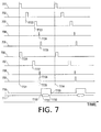
- FIG. 7 is a timing diagram of control signals from the output of light pulses by the controller to the reception of the photoacoustic signals.
- the control unit 122 reads in setting information specified by the user through the operation unit 124 and records it in the internal memory 121.
- the setting information may include the number of irradiation to be repeated at the same measurement point, measurement range, wavelength of the light pulses, and so on.
- the control unit 122 drives the X-Y stage by means of the stage drive unit 116 to move the light projection unit 112 and the probe 111 to a measurement position of the object 104.
- the control unit 122 outputs a control signal through the light source drive circuit 132 to open the shutters 128 and 129. This allows the light pulses from the light sources 126 and 127 to be delivered to the object 104 through the fiber bundles 105 and 106, and to the light input unit 117 through the optical fibers 107 and 108.
- control unit 122 sends a control signal to the light sources 126 and 127 through the light source drive circuit 132 to emit light pulses.
- the processing in this procedure will be described in more detail with reference to the timing diagram of FIG. 7.
- reference numeral 701 represents a reference pulse signal output in the control unit 122 and having periodic rising edges. Let us assume that the reference pulse signal 701 has rising edges at 100 ms intervals. First, by the rising edges of an excitation start signal 702 sent to the light source 126 at time T722, and an excitation start signal 706 sent to the light source 127 at time T726, the flash lamps are turned on to excite the laser medium inside the light sources.
- the Q switches When the laser medium has been sufficiently excited, the Q switches are activated by the rising edges of an oscillation start signal 703 sent to the light source 126 at time T723, and an oscillation start signal sent to the light source 127 at time T727.
- the light source drive circuit 132 adjusts the timing of the excitation start signals and the oscillation start signals to the light sources 126 and 127 such that light pulses 704 and 708 are projected to the object 104 substantially at the same time (T724 and T728), irrespective of the individual variability of the plurality of light sources.
- the duration of a laser pulse is about 10 ns, the adjustment is made so that there is only a time difference of less than 10 ns between time T724 and time T728.
- the light pulses are input not only to the object 104 but also to the light input unit 117, where it is converted to electrical pulse signals 705 and 709 by the optical sensor circuit 118 and sent to the receiving circuit 120 substantially at the same time (T725 and T729).
- the receiving circuit 120 uses a trigger signal from the optical sensor circuit to detect the timing at which the light pulses are projected to the object.
- the photoacoustic wave generated inside the object 104 is then converted into a photoacoustic signal 711 in the probe 111 and transmitted to the receiving circuit 120 at time T731.
- This processing corresponds to step S207 in FIG. 2.
- the receiving circuit 120 converts the analog photoacoustic signal 711 into a digital signal for a certain period of time after the rising edge of the electrical pulse signal from the optical sensor circuit 118, and stores the signal in the internal memory.
- the receiving circuit 120 outputs a conversion start signal 710 to the A/D converter with a rising edge (at T730) before the time T731 at which the photoacoustic signal 711 from the object 104 reaches the receiving circuit 120.
- the convention start signal 710 falls down at time T733 after the time T732 at which the photoacoustic signal 711 from the object has completely reached the receiving circuit (T733).
- Signal averaging is done in this processing to the signals originating from the same point on the object to reduce the effect of noise.
- the thickness of the plate-like member 113, the distance between the plate-like members 113 and 114, and the average sound velocity inside the living body are represented by d1[m], d2[m], and v[m/s], respectively.
- the values d1 and v are calculated beforehand and stored inside the memory 121.
- the value d2 is measured by the distance sensor in the holding mechanism drive unit 115.
- the delay from the projection of light pulses to the object 104 until the trigger signal reaches the receiving circuit is represented by t1[s].
- the time required for the photoacoustic wave 110 to reach the probe 111 is sufficiently longer than the time required for the light pulses to reach the light absorbing segment 109. Therefore, the interval between time T725 and time T731 can be assumed to be d1/v[s], in consideration of the time required for the photoacoustic signal from the object 104 to pass through the plate-like member 113.
- the interval between time T725 and time T732 can be assumed to be (d2 + d1)/v[s], in consideration of the time required for the photoacoustic signal from the entire object 104 to reach the probe.
- a signal processing unit 315 asserts the conversion start signal 710 before time elapses by d1/v - t1[s] from the time T725 at which the trigger signal was input (time T730).
- the unit negates the conversion start signal 710 after time has elapsed by (d2 + d1)/v - t1[s] from time T725 (time T733).
- the photoacoustic signal from the object 104 can all be stored as digital data in the memory 121.
- the digital data is read out by a CPU in the control unit 122, and the digital data obtained from the same point on the object 104 is averaged.
- the data is then input to the image processing circuit 123 for image reconstruction.
- a high-level photoacoustic signal received at an early time is considered to indicate a light absorbing segment located in the object 104 near the probe 111.
- a high-level photoacoustic signal received at a late time is considered to indicate a light absorbing segment located in the object 104 away from the probe 111.
- the optical sensor circuit is accommodated in a different housing from that of the light source unit 102, and information is sent as light pulses, so as to prevent false trigger signals from being generated due to the electromagnetic noise from the light sources 126 and 127.
- step S209 it is determined whether or not the entire measurement range of the object 104 has been measured.
- control unit 122 sends an instruction to the image processing circuit 123, to perform image reconstruction based on photoacoustic signal data of respective measurement points stored in the internal memory of the receiving circuit.
- a diagnostic image indicating the spectral characteristics of the interior of the living body is then output to the display 125.
- FIG. 3 shows the configuration of a substrate inside the controller.
- Reference numeral 301 denotes a fiber connector for connecting the optical fibers 107.
- Reference numeral 302 denotes a fiber connector for connecting the optical fibers 108.
- the fiber connectors 301 and 302 correspond to the "light input unit 117".
- Reference numerals 303 and 304 denote photodiodes that have their light receiving surfaces arranged on the optical axes of the fiber connectors 301 and 302, respectively.
- Reference numerals 305 and 306 denote current-voltage conversion circuits formed by passive devices such as op-amps and resistances. Light pulses entering the photodiodes cause a photocurrent to flow, and a voltage in proportion to the photocurrent is output by the current-voltage conversion circuits 305 and 306.
- Reference numerals 307 and 308 denote comparators formed by comparison circuits.
- the comparator compares the output voltage from the current-voltage conversion circuit 305 or 306 with a constant threshold and increases the voltage to a higher level only when the voltage exceeds the threshold. It keeps the voltage level low if the output voltage equals to or lower than the threshold.
- the pulse width of the light pulses from the light sources 126 and 127 is about 10 ns. Therefore, the pulse width of the output voltage from the current-voltage conversion circuit 305 or 306, or the comparator 307 or 308, is also about 10 ns.
- Reference numerals 309 and 310 denote waveform rectifiers formed by waveform rectification circuits.
- the waveform rectifier increases the pulse width from 10 nanosecond to about 1 microsecond, so that the receiving circuit 120 can more readily detect the light emission timing.
- the waveform rectifier is formed by a monostable multivibrator circuit and a buffer circuit.
- the output pulses from the waveform rectifiers 309 and 310 are called the trigger signal.
- the trigger signal is input to a trigger branch substrate 311.
- the receiving circuit 120 is formed by a plurality of substrates.
- the probe 111 has six hundred ultrasonic sensor elements, so that a cable consisting of six hundred signal lines from the probe 111 is connected to the probe connector 119 for signal input.
- the receiving circuit 120 is formed by four substrates, each being capable of digitizing 150 channels of signals.
- the trigger branch substrate 311 distributes the output signals from the waveform rectifiers 309 and 310 to the four receiving circuit substrates so that the respective substrates operate at the same timing.
- the trigger branch substrate is formed by a high precision buffer circuit.
- the photoacoustic signal input to the probe connector 119 is input to a photoacoustic signal branch substrate 312.
- the photoacoustic signal branch substrate 312 is provided for splitting the 600 channels of photoacoustic signals so that 150 each channels of signals are input to each of the four receiving substrates.
- Reference numeral 313 denotes an amplifier unit formed by a pre-amp for amplifying the photoacoustic signals.
- the amplifier unit 313 amplifies the photoacoustic signals that are as small as about several ten microV to about several mV.
- Reference numeral 314 denotes an A/D conversion unit formed by an A/D conversion circuit for digitizing the amplified photoacoustic signals. The timing for starting and stopping A/D conversion is determined based on a control signal from a signal processing unit to be described later.
- Reference numeral 315 denotes a circuit that performs processing to the photoacoustic signals digitized by the A/D conversion unit 314, and is formed by an FPGA.
- the signal processing unit 315 receives trigger signals distributed by the trigger branch substrate 311. These signals correspond to 705 and 709 in FIG. 7.
- the signal processing unit 315 When the signal processing unit 315 detects rising edges of the trigger signals, it asserts an A/D conversion start signal to the A/D conversion unit 314, to start receiving the photoacoustic signals.
- the data output from the A/D conversion unit is stored consecutively in a memory 316.
- the signal processing unit 315 negates the conversion start signal for the A/D conversion unit to stop the A/D conversion after data has been stored in the memory 316 for a time period that is sufficiently longer than the time required for the photoacoustic waves from the object 104 to be transmitted to the probe 111.
- Reference numeral 317 denotes a conductive housing that is grounded, for accommodating the probe connectors, the fiber connectors, and the optical sensor circuit. Copper, iron, aluminum, conductive plastics or the like are used for the material of the housing. Gaps inside the housing 317 are minimized except for a connector portion for connection with external devices, so as to function as an electromagnetic shield. Electromagnetic noise diffraction from the light source unit 102 or the holding unit 101 can thereby be reduced. As a result, the optical sensor circuit can be prevented from emitting false trigger signals when no light pulse is emitted. This can in turn reduce the possibility of an artifact caused by the signal failure being contained in the diagnostic image.
- the housing need not necessarily take the form shown in FIG.
- the controller 103 which is sensitive to electromagnetic noise, should entirely be accommodated in the housing, to be separated from the light source unit 102.
- the outer coverings of the probe connector 119 and the fiber connectors 301 and 302 are insulated from the housing 317. This prevents noise currents from the holding unit 101 or the light source unit 102 from propagating to the controller 103 via the outer shield of the probe connector or the outer coverings of the fiber connectors, whereby the SN ratio of the photoacoustic signals can be improved.
- the light input unit and the optical sensor circuit are accommodated in the electromagnetically shielded housing so as not to be affected by external devices (in particular, high-power light sources).
- the influence of electromagnetic noise can be reduced by disposing the light detecting components in a housing different from the housing containing the light sources.
- the light input unit and the optical sensor, and the controller are accommodated in the common housing.
- the signal output upon detection of light is less likely to be affected by noise from an external source before being input to the control unit.
- the effect of the present invention can be achieved as long as the light detecting component is shielded from noises originating from light sources.
- the light input unit and the optical sensor may also be shielded from noises originating from light sources if they are accommodated in a housing that is different from the housing containing the light sources, or the housing containing the controller, with the electrical signal upon detection of light being sent to the controller.
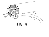
- FIG. 4 shows a diagram of the enlarged input end of the fiber bundle in the optical fiber input unit 130.
- Reference numeral 401 denotes a frame for bundling a multiplicity of optical fibers in a cylindrical form.
- White circles denoted by reference numeral 402 represent optical fibers that guide light pulses from the light source unit to the object 104.
- the optical fibers 402 are bundled into the fiber bundle 105.
- Black circles denoted by reference numeral 403 represent optical fibers that guide light pulses from the light source unit to the controller 103.
- the optical fibers 403 are bundled as the optical fibers 107, which are part of the fiber bundle.
- the optical fibers 403 that connect to the controller 103 are selected such as to be dispersed in the frame 401.
- the number of optical fibers 403 is selected such as to be able to emit a sufficient amount of light to generate a trigger signal to the photodiodes 303.
- the pulsed light beam can be branched without using an additional component such as a beam splitter.
- the light source unit can be disposed away from the controller 103 and the holding unit without requiring strict adjustment of optical paths, so that an easily assemblable apparatus can be realized.
- the optical sensor for generating an A/D conversion start timing signal for the receiving circuit is disposed inside the controller that is placed away from the light source unit. Electromagnetic noise diffracting from the light source is thereby prevented, so that a highly reliable photoacoustic apparatus can be realized.
- the numbers of light sources or directions is not limited to this.
- a pulsed light beam from one light source may be branched inside the light source unit 102 to irradiate the object from two directions.
- the present invention can also be applied to a case where the object is irradiated with light pulses only from one direction.
- the present invention can also be applied to a case where two light sources are provided but light pulses are projected either from the direction of the probe 111 or the direction of the light projection unit 112.
- a photoacoustic apparatus that is more inexpensive than the one using optical fibers can be realized by an appropriate arrangement of positioning means for aligning optical axes and mirrors, prisms and the like for bending the light paths.
- the A/D conversion is started after a certain time period after the signal processing unit 315 received the trigger signal from the optical sensor circuit 118.
- the processing performed in synchronism with the trigger signal is not limited to this.
- the A/D conversion unit 314 may be operated all the time, while the signal processing unit 315 may be controlled to store the signals only in the range where the photoacoustic signals exist, after the reception of the trigger signal, in the memory 316.
- a beam splitter may be provided before the optical fiber input unit 130 inside the light source unit to branch the pulsed light beam, which may be guided to the controller 103 with the use of optical fibers different from the optical fibers 105 and 106.
- the present invention can also be applied to a case where the photodiode 303 is used to measure the light amount or wavelength.
- Embodiment 2 will be described.
- This embodiment is different from Embodiment 1 in that a reflected light beam from the object irradiated with light in pulses is input to the controller.
- Embodiment 1 one example of an apparatus was described in which the object was fixedly sandwiched between plate-like members and automatically scanned with the light projection unit and the probe.
- an example of an apparatus will be described, in which a probe is directly contacted to an object and moved manually by the user to scan the object along its surface.
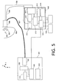
- FIG. 5 is a block diagram illustrating the configuration of a photoacoustic apparatus according to this embodiment.
- Reference numeral 501 denotes a light source unit. The unit differs from the light source unit 102 of Embodiment 1 in that it has one laser system inside instead of two.
- Reference numeral 502 denotes a controller similar to that of Embodiment 1.
- the object 503, light absorbing segment 504, photoacoustic wave 505, and probe 506 are the same as the object 104, light absorbing segment 109, photoacoustic wave 110, and probe 111 of Embodiment 1, respectively, and will not be described again.
- Reference numeral 507 denotes part of a fiber bundle, which is used for guiding light pulses from the light source unit 501 to the object 503 via the probe 506.
- Reference numeral 508 denotes another part of a fiber bundle, which is connected to the controller 502 for signal input to detect light emission timing.
- the fiber bundle connected to the probe 506 is branched into optical fibers 507 connected to the light source unit and optical fibers 508 connected to the controller.
- Reference numeral 509 denotes a cable for transmitting a photoacoustic signal output from the probe 506 to the controller 502.
- the cable 509 and the optical fibers 508 may be bundled into one cable.
- the light input unit 510, optical sensor circuit 511, and light source drive circuit 522 are similar to the light input unit 117, optical sensor circuit 118, and light source drive circuit 132 of Embodiment 1, respectively, except that laser light is generated from one system instead of two.
- the probe connector 512, receiving circuit 513, and memory 514 are the same as those of Embodiment 1 and will not be described again.
- the control unit 515 is a part (unit) that sends instructions to the receiving circuit 513 and the light source drive circuit 522 and controls the overall operation, and is configured by a CPU and software.
- the image processing circuit 516, operation unit 517, and display 518 are the same as the image processing circuit 123, operation unit 124, and display 125 of Embodiment 1, and will not be described again.
- the light source 519, shutter 520, optical fiber input unit 521, and temperature adjusting unit 523 are the same as the light source 126, shutter 128, optical fiber input unit 130, and temperature adjusting unit 133 of Embodiment 1, and will not be described again.
- the operation in this embodiment is different from that of Embodiment 1 in that the probe is moved manually by the user at step S204 of the flowchart in FIG. 2.
- the operation flow other than that, from projection of light to the photoacoustic signal acquisition, is the same as that of Embodiment 1.
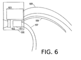
- FIG. 6 is a diagram illustrating the arrangement inside the probe 506.
- Reference numeral 601 denotes an emission end part, or emission ends of the fiber bundles 507 and 508, from which light pulses from the light source unit 501 are projected to the object 503.
- Reference numeral 602 denotes a concave lens arranged opposite the emission end part 601 for adjusting the irradiation density and irradiation pattern of the light emitted from the emission end part 601. The pulsed light beam is reduced in irradiation density as it passes through the concave lens 602 so that it can be projected to the object 503.
- Reference numeral 603 denotes a transducer, which receives a photoacoustic wave and converts it to a photoacoustic signal, and includes arrayed ultrasonic transducer elements forming several hundred channels.
- a fiber bundle similar to the one denoted at reference numeral 401 in FIG. 4 is encased in the emission end part 601.
- a large part of the fiber bundle 402 corresponds to the optical fibers 507 in FIG. 5, which are connected to the optical fiber input unit 521 of the light source unit 501.
- the dispersedly selected optical fibers 403 correspond to the optical fibers 508 in FIG. 5, which are connected to the light input unit 510 inside the controller 502.
- Light pulses from the light source 519 are guided into the probe 506 via the fiber bundle 507 and emitted from the emission end part 601 toward the concave lens 602.
- Light is magnified by the concave lens 601 and projected to the object 503 in pulses, whereupon a photoacoustic wave 505 is generated from a light absorbing segment 504.
- the photoacoustic wave is converted into a photoacoustic signal by the transducer 603, which is transmitted by the cable 509 to the receiving circuit 513 inside the controller.
- part of pulsed light beam emitted from the emission end part 601 is reflected by the surface of the concave lens 602, returns to the emission end part 601, and enters the optical fibers 403.
- the optical fibers 403 are bundled together as the optical fiber member 508 and connected to the controller 502. Therefore, the returned light enters the light input unit 510 and the optical sensor circuit 511, so that a trigger signal is input to the signal processing unit 315 of the receiving circuit 513.
- the signal processing unit 315 When the signal processing unit 315 detects a rising edge of the trigger signal, it asserts an A/D conversion start signal to the A/D conversion unit 314, to start receiving the photoacoustic signal.
- the data output from the A/D conversion unit is stored consecutively in the memory 316.
- the signal processing unit 315 stores data in the memory 316 for a time period that is sufficiently longer than the time required for the photoacoustic wave from the object 503 to reach the probe 506. After that, the conversion start signal for the A/D conversion unit is negated to stop the A/D conversion.
- time T730 and time T733 are determined in this embodiment.
- the distance between the transducer 603 and the object 503, the thickness of the object, and the average sound velocity of the interior of the living body will be represented by d3, d4[m], and v[m/s], respectively.
- the delay from the projection of light pulses to the object 503 until the trigger signal reaches the receiving circuit is represented by t1[s].
- the values d3, d4, and v are calculated beforehand and stored inside the memory 514.
- the time required for the photoacoustic wave 505 to reach the probe 506 is sufficiently longer than the time required for the light pulses to reach the light absorbing segment 504. Therefore, the interval between time T725 and time T731 can be assumed to be d3/v[s], in consideration of the time required for the photoacoustic signal from the object 503 to propagate.
- the interval between time T725 and time T732 can be assumed to be (d3 + d4)/v[s], in consideration of the time required for the photoacoustic signal from the entire object 503 to propagate.
- the signal processing unit 315 asserts the conversion start signal 710 before time elapses by d3/v - t1[s] from the time T725 at which the trigger signal was input (time T730).
- the unit negates the conversion start signal 710 after time has elapsed by (d3 + d4)/v - t1[s] from time T725 (time T733).
- the photoacoustic signals from the object 503 can all be stored as digital data in the memory 316.
- the digital data is read out by a CPU in the control unit 515, and the digital data originating from the same point on the object 503 is averaged.
- the reception timing of the photoacoustic wave is determined by guiding light into a shielded housing, whereby the advantageous effect of the present invention, which is to obtain a favorable diagnostic image with reduced influence of the high voltage, high current laser light source, can be achieved.
- the A/D conversion is started after a certain time period after the signal processing unit 315 received the trigger signal from the optical sensor circuit 511.
- the processing performed in synchronism with the trigger signal is not limited to this.
- the signal processing unit 315 may start A/D conversion at the same time at time T723 when the control unit 515 drives the Q switch of the laser light source 519 via the light source drive circuit 522.
- the signal processing unit may then store the signals only in the range where the photoacoustic signals exist (from time T731 to time T732), after the reception of the trigger signal, in the memory 316.
Abstract
An object information acquiring apparatus is used, with this apparatus including: a light source unit having a light source and a drive circuit driving the light source; a probe converting an acoustic wave generated from an object irradiated with light emitted from the light source into an electrical signal; a light detector detecting the light emitted from the light source and generating a trigger signal; a controller receiving the trigger signal from the light detector and the electrical signal from the probe and generating property information on the inside of the object; and a housing implementing shielding of electromagnetic noise generated from the light source unit. The housing accommodates the light detector such so as to separate the light detector from the light source unit.
Description
The present invention relates to an object information acquiring apparatus.
In medical fields, photoacoustic apparatuses that generate images of internal shapes and functions of an object with the use of the photoacoustic effect have been researched in the past. In a conventional photoacoustic apparatus, upon receiving an instruction from the user, a controller inside the apparatus sends a signal to the drive circuit of a light source to emit light pulses. When an object is irradiated with laser pulses via a light guide, the object generates photoacoustic waves. The photoacoustic waves are received by a probe that is in contact with the object, and converted to an electrical signal called a photoacoustic signal. The controller performs signal processing and image reconstruction to this photoacoustic signal and presents an image for diagnosis to the user.
With the conventional photoacoustic apparatus, it is necessary to project light pulses to the object with a sufficient amount of light in order to increase the contrast of the diagnostic image. For this reason, high power lasers are used as the light source. Driving a flash lamp or Q switch in such laser systems requires high voltage and high current.
There is variation in time between the input of a drive signal from the controller and the actual emission of light pulses due to the individual variability or changes over time of the light sources, because of which the emission timing of light pulses is not constant. Accordingly, a photoacoustic apparatus including an optical sensor for detecting the emission timing of light pulses has been proposed (PTL 1: Patent Literature 1). In the photoacoustic apparatus of Patent Literature 1, part of light delivered in pulses is guided to the optical sensor to detect the emission timing. A receiving circuit controls when to start and stop receiving the photoacoustic signal in synchronism with the emission timing detected by the optical sensor. The position of a light absorbing segment inside the object is estimated based on a time difference between the emission timing and the received signal, to reconstruct an image.
When high power laser such as the one mentioned above is used as the light source, generally, the light source, the light guide, and the optical sensor are accommodated in one housing so that no light pulse leaks to the outside of the housing, for securing safety of the apparatus. An optical component such as a beam splitter or mirror is used as the light guide, to branch and guide the pulsed light beam to the optical sensor.
Meanwhile, an apparatus that uses a fiber bundle as a light guide has been proposed in the field of illumination devices (PTL 2: Patent Literature 2).
In the conventional photoacoustic apparatus, when driving the light source, electromagnetic noise from the drive circuit of the high voltage, high current light source sometimes diffracts to the optical sensor. This may result in malfunctioning of the optical sensor, which adversely affects the synchronization of the emission timing and the photoacoustic wave reception, because of which the image reflecting the condition inside the object may not be generated correctly. To prevent this, the optical sensor could be covered by a shield member or the like to block the noise. However, the influence of electromagnetic noise can be reduced only to a limited extent because of the high intensity of electromagnetic noise from the light source and of the difficulties in providing electromagnetic shields to apertures and connector parts.
The present invention was made in view of the above problem and its object is to reduce the influence of electromagnetic noise from a light source on an optical sensor during photoacoustic measurements.
The present invention provides an object information acquiring apparatus, comprising:
a light source unit including a light source and a drive circuit driving the light source;
a probe configured to convert an acoustic wave generated from an object irradiated with light emitted from the light source into an electrical signal;
a light detector configured to detect the light emitted from the light source and generate a trigger signal;
a controller configured to receive the trigger signal from the light detector and the electrical signal from the probe, and generate property information from the inside of the object; and
a housing configured to implemente shielding of electromagnetic noise generated from the light source unit, wherein
the housing accommodates the light detector so as to separate the light detector from the light source unit.
According to the present invention, the influence of electromagnetic noise from a light source on the optical sensor during photoacoustic measurements can be reduced.
Further features of the present invention will become apparent from the following description of exemplary embodiments with reference to the attached drawings.
Further features of the present invention will become apparent from the following description of exemplary embodiments with reference to the attached drawings.
Preferred embodiments of the present invention will be hereinafter described with reference to the drawings. Note, it is not intended to limit the scope of this invention to the specifics given below, and the sizes, materials, shapes, and relative arrangements or the like of constituent components described below should be changed as required in accordance with the configurations and various conditions of the apparatus to which the invention is applied.
The photoacoustic apparatus of the present invention is an apparatus for obtaining property information on the inside of an object as image data by utilizing the photoacoustic effect, wherein light (electromagnetic wave) is projected to the object and an acoustic wave thereby generated inside the object is received. The property information thus acquired includes source distributions of acoustic waves generated by the irradiation with light, initial sound pressure distributions inside the object, or, light energy absorption density distributions, absorption coefficient distributions, or density distributions of tissue-forming substances, which are deduced from the initial sound pressure distributions. The density distribution of substance may be, for example, an oxygen saturation distribution, or a density distribution of oxidized hemoglobin or reduced hemoglobin. As these properties are also referred to as object information, the photoacoustic apparatus of the present invention can also be called an object information acquiring apparatus.
The acoustic waves, when referred to in the present invention, are typically ultrasound waves, and include elastic waves that are called sound waves, ultrasound waves, or acoustic waves. An acoustic wave generated by the photoacoustic effect is referred to as a "photoacoustic wave", or a "light-induced ultrasound wave". A probe of the object information acquiring apparatus receives the acoustic waves generated inside an object.
<Embodiment 1>
In this embodiment, part of light emitted from a light source is guided into an optical sensor disposed inside a housing of a receiving circuit.
In this embodiment, part of light emitted from a light source is guided into an optical sensor disposed inside a housing of a receiving circuit.
FIG. 1 is a block diagram illustrating a photoacoustic apparatus according to this embodiment. In FIG. 1, reference numeral 101 denotes a holding unit that retains an object, projects light pulses to the object, receives a photoacoustic wave from the object, and converts it into a photoacoustic signal. Reference numeral 102 denotes a light source unit including a light source, a drive circuit for the light source, and an optical system. Reference numeral 103 denotes a controller that receives the photoacoustic signal, performs signal processing and image processing, presents a diagnostic image to the user, and controls the overall operation of the apparatus. Reference numeral 104 denotes the object in the photoacoustic apparatus, which is a body part of a subject. Here it will be described as a human breast, as one example.
A control unit 122 is a section that sends instructions to the receiving circuit 120, the holding mechanism drive unit 115, the stage drive unit 116, and the light source drive circuit 132 and controls the overall operation, and is configured by a CPU and software. Reference numeral 123 denotes an image processing circuit, which reads out the photoacoustic signal data stored in the memory 121, performs image reconstruction, and generates diagnostic image data indicating an absorption coefficient distribution inside the object 104.
The light source unit 102 is shut from the outside by a housing so that no laser light leaks to the outside and that the inside temperature stays constant. Light pulses are projected to the object 104 from the light projection unit 112 and the probe 111 inside the holding unit. As the light projection unit 112 and the probe 111 move on the X-Y plane, the flexible fiber bundles 105 and 106 transmit the light pulses from the light source unit 102 to the holding unit 101. Fiber bundles consist of several hundred optical fibers bundled together. Several fibers are selected from the fiber bundles 105 and 106 such as to be evenly distributed as the optical fibers 107 and 108, for transmitting the light pulses to the controller 103. The controller 103 starts acquiring the photoacoustic signal from the probe 111 in synchronism with the timing at which the light pulses are received.
FIG. 2 shows the operation flow of an in-vivo examination apparatus carried out by the controller 103. FIG. 7 is a timing diagram of control signals from the output of light pulses by the controller to the reception of the photoacoustic signals.
At Step S201, the control unit 122 checks whether or not it is ready to start a measurement, based on a signal from the proximity sensor in the holding mechanism drive unit 115. If the object 104 is retained between the plate-like members 113 and 114 (S201 = Yes), it is determined to be ready to start the measurement, and the process goes to step S203. If it is not ready to start measurement (S201 = No), the process goes to step S202, and after a certain period of waiting, the process returns to step S201.
At step S203, the control unit 122 reads in setting information specified by the user through the operation unit 124 and records it in the internal memory 121. The setting information may include the number of irradiation to be repeated at the same measurement point, measurement range, wavelength of the light pulses, and so on.
At step S204, the control unit 122 drives the X-Y stage by means of the stage drive unit 116 to move the light projection unit 112 and the probe 111 to a measurement position of the object 104.
At step S205, thecontrol unit 122 outputs a control signal through the light source drive circuit 132 to open the shutters 128 and 129. This allows the light pulses from the light sources 126 and 127 to be delivered to the object 104 through the fiber bundles 105 and 106, and to the light input unit 117 through the optical fibers 107 and 108.
At step S205, the
At step S206, the control unit 122 sends a control signal to the light sources 126 and 127 through the light source drive circuit 132 to emit light pulses. The processing in this procedure will be described in more detail with reference to the timing diagram of FIG. 7.
In FIG. 7, reference numeral 701 represents a reference pulse signal output in the control unit 122 and having periodic rising edges. Let us assume that the reference pulse signal 701 has rising edges at 100 ms intervals. First, by the rising edges of an excitation start signal 702 sent to the light source 126 at time T722, and an excitation start signal 706 sent to the light source 127 at time T726, the flash lamps are turned on to excite the laser medium inside the light sources.
When the laser medium has been sufficiently excited, the Q switches are activated by the rising edges of an oscillation start signal 703 sent to the light source 126 at time T723, and an oscillation start signal sent to the light source 127 at time T727. This brings about rapid oscillation inside the laser medium, whereby light pulses with extremely high energy are emitted. The light source drive circuit 132 adjusts the timing of the excitation start signals and the oscillation start signals to the light sources 126 and 127 such that light pulses 704 and 708 are projected to the object 104 substantially at the same time (T724 and T728), irrespective of the individual variability of the plurality of light sources. As the duration of a laser pulse is about 10 ns, the adjustment is made so that there is only a time difference of less than 10 ns between time T724 and time T728.
At this time, the light pulses are input not only to the object 104 but also to the light input unit 117, where it is converted to electrical pulse signals 705 and 709 by the optical sensor circuit 118 and sent to the receiving circuit 120 substantially at the same time (T725 and T729). There is a delay of several hundred nanosecond to several microsecond between time T723 and time T724 and between time T727 and time T728, which varies depending on the individual variability or changes over time of the flash lamps inside the light sources. Therefore, the receiving circuit 120 uses a trigger signal from the optical sensor circuit to detect the timing at which the light pulses are projected to the object.
The photoacoustic wave generated inside the object 104 is then converted into a photoacoustic signal 711 in the probe 111 and transmitted to the receiving circuit 120 at time T731. This processing corresponds to step S207 in FIG. 2. At step S207, the receiving circuit 120 converts the analog photoacoustic signal 711 into a digital signal for a certain period of time after the rising edge of the electrical pulse signal from the optical sensor circuit 118, and stores the signal in the internal memory. For this purpose, the receiving circuit 120 outputs a conversion start signal 710 to the A/D converter with a rising edge (at T730) before the time T731 at which the photoacoustic signal 711 from the object 104 reaches the receiving circuit 120. The convention start signal 710 falls down at time T733 after the time T732 at which the photoacoustic signal 711 from the object has completely reached the receiving circuit (T733). Signal averaging is done in this processing to the signals originating from the same point on the object to reduce the effect of noise.
Next, how time T730 and time T733 are determined will be explained. The thickness of the plate-like member 113, the distance between the plate- like members 113 and 114, and the average sound velocity inside the living body are represented by d1[m], d2[m], and v[m/s], respectively. The values d1 and v are calculated beforehand and stored inside the memory 121. The value d2 is measured by the distance sensor in the holding mechanism drive unit 115. The delay from the projection of light pulses to the object 104 until the trigger signal reaches the receiving circuit is represented by t1[s].
The time required for the photoacoustic wave 110 to reach the probe 111 is sufficiently longer than the time required for the light pulses to reach the light absorbing segment 109. Therefore, the interval between time T725 and time T731 can be assumed to be d1/v[s], in consideration of the time required for the photoacoustic signal from the object 104 to pass through the plate-like member 113. The interval between time T725 and time T732 can be assumed to be (d2 + d1)/v[s], in consideration of the time required for the photoacoustic signal from the entire object 104 to reach the probe. Therefore, a signal processing unit 315 asserts the conversion start signal 710 before time elapses by d1/v - t1[s] from the time T725 at which the trigger signal was input (time T730). The unit negates the conversion start signal 710 after time has elapsed by (d2 + d1)/v - t1[s] from time T725 (time T733).
Thus the photoacoustic signal from the object 104 can all be stored as digital data in the memory 121. The digital data is read out by a CPU in the control unit 122, and the digital data obtained from the same point on the object 104 is averaged. The data is then input to the image processing circuit 123 for image reconstruction. A high-level photoacoustic signal received at an early time is considered to indicate a light absorbing segment located in the object 104 near the probe 111. A high-level photoacoustic signal received at a late time is considered to indicate a light absorbing segment located in the object 104 away from the probe 111.
If image reconstruction is made from data acquired based on wrong trigger signals, the time-photoacoustic signal correspondence will be lost, as a result of which an artifact may be drawn at a wrong position on the diagnostic image.
With the present invention, the optical sensor circuit is accommodated in a different housing from that of thelight source unit 102, and information is sent as light pulses, so as to prevent false trigger signals from being generated due to the electromagnetic noise from the light sources 126 and 127.
With the present invention, the optical sensor circuit is accommodated in a different housing from that of the
Referring back to FIG. 2, the operation flow will further be described. At step S208, it is determined whether or not the number of times of storing the photoacoustic signal in the internal memory has reached the number of times of irradiation to be repeated that has been read in at step S203. If the number has reached the read-in value (S208 = Yes), the process proceeds to step S209, and if not (S208 = No), the process goes back to step S206. If, for example, number 3 has been read in at step S203 as the number of times of irradiation to be repeated, the processes of steps S206 and S207 are repeated three times, before the process proceeds to step S209.
At step S209, it is determined whether or not the entire measurement range of the object 104 has been measured. The range to be measured has been read in at step S203. If the measurement has been completed in the entire measurement range (S209 = Yes), the process goes to step S210. If there is still a portion that has not been measured yet (S209 = No), the process goes back to step S204, from where the process is continued.
At step S210, the control unit 122 sends an instruction to the image processing circuit 123, to perform image reconstruction based on photoacoustic signal data of respective measurement points stored in the internal memory of the receiving circuit. A diagnostic image indicating the spectral characteristics of the interior of the living body is then output to the display 125.
FIG. 3 shows the configuration of a substrate inside the controller.
Reference numeral 301 denotes a fiber connector for connecting the optical fibers 107. Reference numeral 302 denotes a fiber connector for connecting the optical fibers 108. The fiber connectors 301 and 302 correspond to the "light input unit 117".
Generally, the receiving circuit 120 is formed by a plurality of substrates. In this embodiment, the probe 111 has six hundred ultrasonic sensor elements, so that a cable consisting of six hundred signal lines from the probe 111 is connected to the probe connector 119 for signal input. The receiving circuit 120 is formed by four substrates, each being capable of digitizing 150 channels of signals.
The trigger branch substrate 311 distributes the output signals from the waveform rectifiers 309 and 310 to the four receiving circuit substrates so that the respective substrates operate at the same timing. The trigger branch substrate is formed by a high precision buffer circuit. The photoacoustic signal input to the probe connector 119, on the other hand, is input to a photoacoustic signal branch substrate 312. The photoacoustic signal branch substrate 312 is provided for splitting the 600 channels of photoacoustic signals so that 150 each channels of signals are input to each of the four receiving substrates.
When the signal processing unit 315 detects rising edges of the trigger signals, it asserts an A/D conversion start signal to the A/D conversion unit 314, to start receiving the photoacoustic signals. The data output from the A/D conversion unit is stored consecutively in a memory 316. The signal processing unit 315 negates the conversion start signal for the A/D conversion unit to stop the A/D conversion after data has been stored in the memory 316 for a time period that is sufficiently longer than the time required for the photoacoustic waves from the object 104 to be transmitted to the probe 111.
The outer coverings of the probe connector 119 and the fiber connectors 301 and 302 are insulated from the housing 317. This prevents noise currents from the holding unit 101 or the light source unit 102 from propagating to the controller 103 via the outer shield of the probe connector or the outer coverings of the fiber connectors, whereby the SN ratio of the photoacoustic signals can be improved.
In this embodiment, the light input unit and the optical sensor circuit are accommodated in the electromagnetically shielded housing so as not to be affected by external devices (in particular, high-power light sources). The influence of electromagnetic noise can be reduced by disposing the light detecting components in a housing different from the housing containing the light sources.
In this embodiment, further, the light input unit and the optical sensor, and the controller are accommodated in the common housing. Thereby, the signal output upon detection of light, even though it is a small electrical signal, is less likely to be affected by noise from an external source before being input to the control unit. Note, the effect of the present invention can be achieved as long as the light detecting component is shielded from noises originating from light sources. For example, the light input unit and the optical sensor may also be shielded from noises originating from light sources if they are accommodated in a housing that is different from the housing containing the light sources, or the housing containing the controller, with the electrical signal upon detection of light being sent to the controller.
FIG. 4 shows a diagram of the enlarged input end of the fiber bundle in the optical fiber input unit 130. Reference numeral 401 denotes a frame for bundling a multiplicity of optical fibers in a cylindrical form. White circles denoted by reference numeral 402 represent optical fibers that guide light pulses from the light source unit to the object 104. The optical fibers 402 are bundled into the fiber bundle 105. Black circles denoted by reference numeral 403 represent optical fibers that guide light pulses from the light source unit to the controller 103. The optical fibers 403 are bundled as the optical fibers 107, which are part of the fiber bundle. The optical fibers 403 that connect to the controller 103 are selected such as to be dispersed in the frame 401. The number of optical fibers 403 is selected such as to be able to emit a sufficient amount of light to generate a trigger signal to the photodiodes 303.
By using part of the optical fibers from the light source unit 102 to the holding unit 101 as a branch to the controller 103, the pulsed light beam can be branched without using an additional component such as a beam splitter. As signals are sent between the light source unit 102, the holding unit 101, and the controller 103 via optical fibers, the light source unit can be disposed away from the controller 103 and the holding unit without requiring strict adjustment of optical paths, so that an easily assemblable apparatus can be realized.
As has been described above, according to Embodiment 1 of the present invention, the optical sensor for generating an A/D conversion start timing signal for the receiving circuit is disposed inside the controller that is placed away from the light source unit. Electromagnetic noise diffracting from the light source is thereby prevented, so that a highly reliable photoacoustic apparatus can be realized.
While one example was described in this embodiment wherein two light sources were provided and the object was irradiated with light pulses from two directions, the numbers of light sources or directions is not limited to this. For example, a pulsed light beam from one light source may be branched inside the light source unit 102 to irradiate the object from two directions. The present invention can also be applied to a case where the object is irradiated with light pulses only from one direction. The present invention can also be applied to a case where two light sources are provided but light pulses are projected either from the direction of the probe 111 or the direction of the light projection unit 112.
While one example was described in this embodiment in which signals were sent from the light sources to the holding unit and the controller via the optical fibers, the present invention can also be applied to a case where part or all of the light guiding unit is replaced by signal transmission through space. A photoacoustic apparatus that is more inexpensive than the one using optical fibers can be realized by an appropriate arrangement of positioning means for aligning optical axes and mirrors, prisms and the like for bending the light paths.
In the processing at step S207 of this embodiment, the A/D conversion is started after a certain time period after the signal processing unit 315 received the trigger signal from the optical sensor circuit 118. The processing performed in synchronism with the trigger signal is not limited to this. For example, the A/D conversion unit 314 may be operated all the time, while the signal processing unit 315 may be controlled to store the signals only in the range where the photoacoustic signals exist, after the reception of the trigger signal, in the memory 316.
While some optical fibers of the fiber bundles from the light source unit to the holding unit are connected to the controller thereby to branch the pulsed light beam in this embodiment, the method of branching the light is not limited to this. For example, a beam splitter may be provided before the optical fiber input unit 130 inside the light source unit to branch the pulsed light beam, which may be guided to the controller 103 with the use of optical fibers different from the optical fibers 105 and 106.
While the signal from the photodiode 303 is used to determine the reception timing of the photoacoustic signal in this embodiment, the present invention can also be applied to a case where the photodiode 303 is used to measure the light amount or wavelength.
<Embodiment 2>
Next, Embodiment 2 will be described. This embodiment is different from Embodiment 1 in that a reflected light beam from the object irradiated with light in pulses is input to the controller. In Embodiment 1, one example of an apparatus was described in which the object was fixedly sandwiched between plate-like members and automatically scanned with the light projection unit and the probe. In this embodiment, an example of an apparatus will be described, in which a probe is directly contacted to an object and moved manually by the user to scan the object along its surface.
Next, Embodiment 2 will be described. This embodiment is different from Embodiment 1 in that a reflected light beam from the object irradiated with light in pulses is input to the controller. In Embodiment 1, one example of an apparatus was described in which the object was fixedly sandwiched between plate-like members and automatically scanned with the light projection unit and the probe. In this embodiment, an example of an apparatus will be described, in which a probe is directly contacted to an object and moved manually by the user to scan the object along its surface.
FIG. 5 is a block diagram illustrating the configuration of a photoacoustic apparatus according to this embodiment.
Reference numeral 501 denotes a light source unit. The unit differs from the light source unit 102 of Embodiment 1 in that it has one laser system inside instead of two. Reference numeral 502 denotes a controller similar to that of Embodiment 1. The object 503, light absorbing segment 504, photoacoustic wave 505, and probe 506 are the same as the object 104, light absorbing segment 109, photoacoustic wave 110, and probe 111 of Embodiment 1, respectively, and will not be described again.
The light input unit 510, optical sensor circuit 511, and light source drive circuit 522 are similar to the light input unit 117, optical sensor circuit 118, and light source drive circuit 132 of Embodiment 1, respectively, except that laser light is generated from one system instead of two.
The probe connector 512, receiving circuit 513, and memory 514 are the same as those of Embodiment 1 and will not be described again. The control unit 515 is a part (unit) that sends instructions to the receiving circuit 513 and the light source drive circuit 522 and controls the overall operation, and is configured by a CPU and software.
The image processing circuit 516, operation unit 517, and display 518 are the same as the image processing circuit 123, operation unit 124, and display 125 of Embodiment 1, and will not be described again. The light source 519, shutter 520, optical fiber input unit 521, and temperature adjusting unit 523 are the same as the light source 126, shutter 128, optical fiber input unit 130, and temperature adjusting unit 133 of Embodiment 1, and will not be described again.
The operation in this embodiment is different from that of Embodiment 1 in that the probe is moved manually by the user at step S204 of the flowchart in FIG. 2. The operation flow other than that, from projection of light to the photoacoustic signal acquisition, is the same as that of Embodiment 1.
FIG. 6 is a diagram illustrating the arrangement inside the probe 506. Reference numeral 601 denotes an emission end part, or emission ends of the fiber bundles 507 and 508, from which light pulses from the light source unit 501 are projected to the object 503. Reference numeral 602 denotes a concave lens arranged opposite the emission end part 601 for adjusting the irradiation density and irradiation pattern of the light emitted from the emission end part 601. The pulsed light beam is reduced in irradiation density as it passes through the concave lens 602 so that it can be projected to the object 503. Reference numeral 603 denotes a transducer, which receives a photoacoustic wave and converts it to a photoacoustic signal, and includes arrayed ultrasonic transducer elements forming several hundred channels.
A fiber bundle similar to the one denoted at reference numeral 401 in FIG. 4 is encased in the emission end part 601. A large part of the fiber bundle 402 corresponds to the optical fibers 507 in FIG. 5, which are connected to the optical fiber input unit 521 of the light source unit 501. The dispersedly selected optical fibers 403 correspond to the optical fibers 508 in FIG. 5, which are connected to the light input unit 510 inside the controller 502.
Light pulses from the light source 519 are guided into the probe 506 via the fiber bundle 507 and emitted from the emission end part 601 toward the concave lens 602. Light is magnified by the concave lens 601 and projected to the object 503 in pulses, whereupon a photoacoustic wave 505 is generated from a light absorbing segment 504. The photoacoustic wave is converted into a photoacoustic signal by the transducer 603, which is transmitted by the cable 509 to the receiving circuit 513 inside the controller. In this process, part of pulsed light beam emitted from the emission end part 601 is reflected by the surface of the concave lens 602, returns to the emission end part 601, and enters the optical fibers 403. The optical fibers 403 are bundled together as the optical fiber member 508 and connected to the controller 502. Therefore, the returned light enters the light input unit 510 and the optical sensor circuit 511, so that a trigger signal is input to the signal processing unit 315 of the receiving circuit 513.
When the signal processing unit 315 detects a rising edge of the trigger signal, it asserts an A/D conversion start signal to the A/D conversion unit 314, to start receiving the photoacoustic signal. The data output from the A/D conversion unit is stored consecutively in the memory 316. The signal processing unit 315 stores data in the memory 316 for a time period that is sufficiently longer than the time required for the photoacoustic wave from the object 503 to reach the probe 506. After that, the conversion start signal for the A/D conversion unit is negated to stop the A/D conversion.
How time T730 and time T733 are determined in this embodiment will be explained. The distance between the transducer 603 and the object 503, the thickness of the object, and the average sound velocity of the interior of the living body will be represented by d3, d4[m], and v[m/s], respectively. The delay from the projection of light pulses to the object 503 until the trigger signal reaches the receiving circuit is represented by t1[s]. The values d3, d4, and v are calculated beforehand and stored inside the memory 514.
The time required for the photoacoustic wave 505 to reach the probe 506 is sufficiently longer than the time required for the light pulses to reach the light absorbing segment 504. Therefore, the interval between time T725 and time T731 can be assumed to be d3/v[s], in consideration of the time required for the photoacoustic signal from the object 503 to propagate. The interval between time T725 and time T732 can be assumed to be (d3 + d4)/v[s], in consideration of the time required for the photoacoustic signal from the entire object 503 to propagate. The signal processing unit 315 asserts the conversion start signal 710 before time elapses by d3/v - t1[s] from the time T725 at which the trigger signal was input (time T730). The unit negates the conversion start signal 710 after time has elapsed by (d3 + d4)/v - t1[s] from time T725 (time T733). Thus the photoacoustic signals from the object 503 can all be stored as digital data in the memory 316. The digital data is read out by a CPU in the control unit 515, and the digital data originating from the same point on the object 503 is averaged.
In this embodiment, too, the reception timing of the photoacoustic wave is determined by guiding light into a shielded housing, whereby the advantageous effect of the present invention, which is to obtain a favorable diagnostic image with reduced influence of the high voltage, high current laser light source, can be achieved.
In this embodiment, moreover, by inputting part of the light returning from the probe 506 to the controller 502, it is also possible to detect whether or not the light pulses are actually being delivered to the object 503, in addition to the detection of the light emission timing.
There can be a failure in which light pulses are not correctly delivered to the object, even though thecontrol unit 515 is driving the light source 519 via the light source drive circuit 522 to emit light and opening the shutter 520, due to a disconnection failure of the fiber bundle 507 or other failures in the emission end part 601. Even in such a case, a photoacoustic apparatus having the configuration of this embodiment is more reliable, as it can detect such a failure in which light pulses are not correctly being delivered to the object.
There can be a failure in which light pulses are not correctly delivered to the object, even though the
In the processing at step S207 of this embodiment, the A/D conversion is started after a certain time period after the signal processing unit 315 received the trigger signal from the optical sensor circuit 511. The processing performed in synchronism with the trigger signal is not limited to this.
For example, the signal processing unit 315 may start A/D conversion at the same time at time T723 when the control unit 515 drives the Q switch of the laser light source 519 via the light source drive circuit 522. The signal processing unit may then store the signals only in the range where the photoacoustic signals exist (from time T731 to time T732), after the reception of the trigger signal, in the memory 316. By starting A/D conversion before the projection of laser pulses in this way, the photoacoustic signal from the optical sensor circuit can reliably be acquired, even in a case where the photoacoustic signal reaches the probe before the trigger signal due to a long delay in the optical sensor circuit.
While the present invention has been described with reference to exemplary embodiments, it is to be understood that the invention is not limited to the disclosed exemplary embodiments. The scope of the following claims is to be accorded the broadest interpretation so as to encompass all such modifications and equivalent structures and functions.
This application claims the benefit of Japanese Patent Application No. 2012-69673, filed on March 26, 2012, which is hereby incorporated by reference herein in its entirety.
Claims (6)
- An object information acquiring apparatus, comprising:
a light source unit including a light source and a drive circuit driving the light source;
a probe configured to convert an acoustic wave generated from an object irradiated with light emitted from the light source into an electrical signal;
a light detector configured to detect the light emitted from the light source and generate a trigger signal;
a controller configured to receive the trigger signal from the light detector and the electrical signal from the probe, and generate property information from the inside of the object; and
a housing configured to implemente shielding of electromagnetic noise generated from the light source unit, wherein
the housing accommodates the light detector so as to separate the light detector from the light source unit.
- The object information acquiring apparatus according to claim 1, further comprising:
a light guiding unit configured to guide the light emitted from the light source to the object; and
an input unit configured to input the light emitted from the light source into the housing, wherein
the light guiding unit is a fiber bundle, and
the input unit is a portion of fibers forming the fiber bundle.
- The object information acquiring apparatus according to claim 2, wherein the input unit branches the light projected from the light source to the object in order to input part of the light into the housing.
- The object information acquiring apparatus according to claim 2, wherein the input unit inputs a reflected light beam from the object irradiated with light from the light guiding unit into the housing.
- The object information acquiring apparatus according to any one of claims 1 to 4, wherein the housing accommodating the light detector also accommodates the controller.
- The object information acquiring apparatus according to any one of claims 1 to 5, wherein the controller determines, based on the trigger signal, a portion of the electrical signal as a component based on the acoustic wave generated from the object and generates property information on the inside of the object by using the electrical signal component based on the acoustic wave generated from the object.
Applications Claiming Priority (2)
| Application Number | Priority Date | Filing Date | Title |
|---|---|---|---|
| JP2012-069673 | 2012-03-26 | ||
| JP2012069673A JP6124503B2 (en) | 2012-03-26 | 2012-03-26 | Subject information acquisition device |
Publications (1)
| Publication Number | Publication Date |
|---|---|
| WO2013145659A1 true WO2013145659A1 (en) | 2013-10-03 |
Family
ID=48142843
Family Applications (1)
| Application Number | Title | Priority Date | Filing Date |
|---|---|---|---|
| PCT/JP2013/001931 WO2013145659A1 (en) | 2012-03-26 | 2013-03-21 | Object information acquiring apparatus |
Country Status (2)
| Country | Link |
|---|---|
| JP (1) | JP6124503B2 (en) |
| WO (1) | WO2013145659A1 (en) |
Cited By (1)
| Publication number | Priority date | Publication date | Assignee | Title |
|---|---|---|---|---|
| CN108542358A (en) * | 2018-05-14 | 2018-09-18 | 广州中康科技发展有限公司 | The device and method of pulse condition 7 degree of freedom automatic acquisition of scientific information based on photoacoustic imaging |
Families Citing this family (2)
| Publication number | Priority date | Publication date | Assignee | Title |
|---|---|---|---|---|
| JP6388360B2 (en) * | 2013-12-27 | 2018-09-12 | キヤノン株式会社 | SUBJECT INFORMATION ACQUISITION DEVICE AND METHOD FOR CONTROLLING SUBJECT INFORMATION ACQUISITION DEVICE |
| JP6353768B2 (en) * | 2014-11-14 | 2018-07-04 | 富士フイルム株式会社 | Probe and photoacoustic measuring device |
Citations (9)
| Publication number | Priority date | Publication date | Assignee | Title |
|---|---|---|---|---|
| US6184521B1 (en) * | 1998-01-06 | 2001-02-06 | Masimo Corporation | Photodiode detector with integrated noise shielding |
| JP2001174410A (en) | 1999-12-21 | 2001-06-29 | Nkk Corp | Lighting apparatus |
| DE202006016617U1 (en) * | 2006-10-25 | 2007-01-04 | Schramm, Werner, Dr.-Ing. | Device for measuring the energy metabolism of living tissue by laser spectroscopy comprises a laser and an optoelectronic unit connected to a probe and an analysis and display unit through disconnectable interfaces |
| US20100049018A1 (en) * | 2006-11-14 | 2010-02-25 | Karen Duffy | Apparatus for spectrometric based oximetry |
| US20100285518A1 (en) * | 2009-04-20 | 2010-11-11 | The Curators Of The University Of Missouri | Photoacoustic detection of analytes in solid tissue and detection system |
| US20110112382A1 (en) * | 2009-11-12 | 2011-05-12 | Nellcor Puritan Bennett Llc | Systems and methods for combined physiological sensors |
| US20110217762A1 (en) * | 2006-07-11 | 2011-09-08 | The Curators Of The University Of Missouri | Photo-acoustic detection device and method |
| JP2011229556A (en) | 2010-04-23 | 2011-11-17 | Canon Inc | Photoacoustic tomography apparatus and control method therefor |
| JP2012069673A (en) | 2010-09-22 | 2012-04-05 | Sony Corp | Flexible substrate, packaging method of flexible substrate and luminaire |
Family Cites Families (1)
| Publication number | Priority date | Publication date | Assignee | Title |
|---|---|---|---|---|
| JP2012005624A (en) * | 2010-06-24 | 2012-01-12 | Fujifilm Corp | Ultrasonic photoacoustic imaging apparatus and operation method of the same |
-
2012
- 2012-03-26 JP JP2012069673A patent/JP6124503B2/en active Active
-
2013
- 2013-03-21 WO PCT/JP2013/001931 patent/WO2013145659A1/en active Application Filing
Patent Citations (9)
| Publication number | Priority date | Publication date | Assignee | Title |
|---|---|---|---|---|
| US6184521B1 (en) * | 1998-01-06 | 2001-02-06 | Masimo Corporation | Photodiode detector with integrated noise shielding |
| JP2001174410A (en) | 1999-12-21 | 2001-06-29 | Nkk Corp | Lighting apparatus |
| US20110217762A1 (en) * | 2006-07-11 | 2011-09-08 | The Curators Of The University Of Missouri | Photo-acoustic detection device and method |
| DE202006016617U1 (en) * | 2006-10-25 | 2007-01-04 | Schramm, Werner, Dr.-Ing. | Device for measuring the energy metabolism of living tissue by laser spectroscopy comprises a laser and an optoelectronic unit connected to a probe and an analysis and display unit through disconnectable interfaces |
| US20100049018A1 (en) * | 2006-11-14 | 2010-02-25 | Karen Duffy | Apparatus for spectrometric based oximetry |
| US20100285518A1 (en) * | 2009-04-20 | 2010-11-11 | The Curators Of The University Of Missouri | Photoacoustic detection of analytes in solid tissue and detection system |
| US20110112382A1 (en) * | 2009-11-12 | 2011-05-12 | Nellcor Puritan Bennett Llc | Systems and methods for combined physiological sensors |
| JP2011229556A (en) | 2010-04-23 | 2011-11-17 | Canon Inc | Photoacoustic tomography apparatus and control method therefor |
| JP2012069673A (en) | 2010-09-22 | 2012-04-05 | Sony Corp | Flexible substrate, packaging method of flexible substrate and luminaire |
Cited By (2)
| Publication number | Priority date | Publication date | Assignee | Title |
|---|---|---|---|---|
| CN108542358A (en) * | 2018-05-14 | 2018-09-18 | 广州中康科技发展有限公司 | The device and method of pulse condition 7 degree of freedom automatic acquisition of scientific information based on photoacoustic imaging |
| CN108542358B (en) * | 2018-05-14 | 2023-04-25 | 广州中康资讯股份有限公司 | Equipment and method for automatically acquiring seven-dimensional pulse condition information based on photoacoustic imaging |
Also Published As
| Publication number | Publication date |
|---|---|
| JP2013198657A (en) | 2013-10-03 |
| JP6124503B2 (en) | 2017-05-10 |
Similar Documents
| Publication | Publication Date | Title |
|---|---|---|
| JP5553672B2 (en) | Acoustic wave measuring apparatus and acoustic wave measuring method | |
| US9433355B2 (en) | Photoacoustic imaging apparatus and photoacoustic imaging method | |
| US20120302866A1 (en) | Photoacoustic imaging apparatus and photoacoustic imaging method | |
| US20140051969A1 (en) | Object information acquiring apparatus and method of controlling the same | |
| US10098547B2 (en) | Photoacoustic measurement device, photoacoustic measurement method, and probe contact determination method | |
| JP2016047237A (en) | Subject information acquisition apparatus and processing method | |
| JP2012135610A (en) | Probe for photoacoustic inspection and photoacoustic inspection device | |
| US20170049331A1 (en) | Object information acquiring apparatus and method of controlling the same | |
| EP2724665A2 (en) | Object information acquiring apparatus and cover for photoacoustic probe | |
| US20150182123A1 (en) | Object information acquiring apparatus and control method for the object information acquiring apparatus | |
| WO2012067048A1 (en) | Photoacoustic measuring device and method | |
| US11058357B2 (en) | Acoustic wave apparatus and control method thereof | |
| WO2013145659A1 (en) | Object information acquiring apparatus | |
| JP6172912B2 (en) | Subject information acquisition apparatus and photoacoustic probe | |
| US10238297B2 (en) | Object information acquiring apparatus | |
| WO2014156408A1 (en) | Object information acquiring apparatus and control method thereof | |
| JP6309077B2 (en) | Subject information acquisition device | |
| JP6362666B2 (en) | Subject information acquisition device | |
| US20170319077A1 (en) | Sample information acquisition apparatus | |
| US20190130553A1 (en) | Information processing apparatus and information processing method | |
| JP5774159B2 (en) | Acoustic wave measuring apparatus and acoustic wave measuring method | |
| JP6463414B2 (en) | Acoustic wave probe and acoustic wave device | |
| JP2015186555A (en) | Scanner and photoacoustic measurement apparatus | |
| JP5868458B2 (en) | measuring device | |
| JP2020005867A (en) | Acoustic wave probe and method for installing acoustic wave probe |
Legal Events
| Date | Code | Title | Description |
|---|---|---|---|
| 121 | Ep: the epo has been informed by wipo that ep was designated in this application |
Ref document number: 13717570 Country of ref document: EP Kind code of ref document: A1 |
|
| NENP | Non-entry into the national phase |
Ref country code: DE |
|
| 122 | Ep: pct application non-entry in european phase |
Ref document number: 13717570 Country of ref document: EP Kind code of ref document: A1 |