WO2013158308A1 - Self-suspending proppants for hydraulic fracturing - Google Patents
Self-suspending proppants for hydraulic fracturing Download PDFInfo
- Publication number
- WO2013158308A1 WO2013158308A1 PCT/US2013/032435 US2013032435W WO2013158308A1 WO 2013158308 A1 WO2013158308 A1 WO 2013158308A1 US 2013032435 W US2013032435 W US 2013032435W WO 2013158308 A1 WO2013158308 A1 WO 2013158308A1
- Authority
- WO
- WIPO (PCT)
- Prior art keywords
- proppant
- polymer
- modified
- sand
- hydrogel
- Prior art date
Links
Classifications
-
- C—CHEMISTRY; METALLURGY
- C09—DYES; PAINTS; POLISHES; NATURAL RESINS; ADHESIVES; COMPOSITIONS NOT OTHERWISE PROVIDED FOR; APPLICATIONS OF MATERIALS NOT OTHERWISE PROVIDED FOR
- C09K—MATERIALS FOR MISCELLANEOUS APPLICATIONS, NOT PROVIDED FOR ELSEWHERE
- C09K8/00—Compositions for drilling of boreholes or wells; Compositions for treating boreholes or wells, e.g. for completion or for remedial operations
- C09K8/60—Compositions for stimulating production by acting on the underground formation
- C09K8/80—Compositions for reinforcing fractures, e.g. compositions of proppants used to keep the fractures open
- C09K8/805—Coated proppants
-
- C—CHEMISTRY; METALLURGY
- C09—DYES; PAINTS; POLISHES; NATURAL RESINS; ADHESIVES; COMPOSITIONS NOT OTHERWISE PROVIDED FOR; APPLICATIONS OF MATERIALS NOT OTHERWISE PROVIDED FOR
- C09K—MATERIALS FOR MISCELLANEOUS APPLICATIONS, NOT PROVIDED FOR ELSEWHERE
- C09K8/00—Compositions for drilling of boreholes or wells; Compositions for treating boreholes or wells, e.g. for completion or for remedial operations
- C09K8/60—Compositions for stimulating production by acting on the underground formation
- C09K8/62—Compositions for forming crevices or fractures
- C09K8/66—Compositions based on water or polar solvents
- C09K8/68—Compositions based on water or polar solvents containing organic compounds
- C09K8/685—Compositions based on water or polar solvents containing organic compounds containing cross-linking agents
-
- E—FIXED CONSTRUCTIONS
- E21—EARTH DRILLING; MINING
- E21B—EARTH DRILLING, e.g. DEEP DRILLING; OBTAINING OIL, GAS, WATER, SOLUBLE OR MELTABLE MATERIALS OR A SLURRY OF MINERALS FROM WELLS
- E21B43/00—Methods or apparatus for obtaining oil, gas, water, soluble or meltable materials or a slurry of minerals from wells
- E21B43/25—Methods for stimulating production
- E21B43/26—Methods for stimulating production by forming crevices or fractures
- E21B43/267—Methods for stimulating production by forming crevices or fractures reinforcing fractures by propping
-
- Y—GENERAL TAGGING OF NEW TECHNOLOGICAL DEVELOPMENTS; GENERAL TAGGING OF CROSS-SECTIONAL TECHNOLOGIES SPANNING OVER SEVERAL SECTIONS OF THE IPC; TECHNICAL SUBJECTS COVERED BY FORMER USPC CROSS-REFERENCE ART COLLECTIONS [XRACs] AND DIGESTS
- Y10—TECHNICAL SUBJECTS COVERED BY FORMER USPC
- Y10S—TECHNICAL SUBJECTS COVERED BY FORMER USPC CROSS-REFERENCE ART COLLECTIONS [XRACs] AND DIGESTS
- Y10S507/00—Earth boring, well treating, and oil field chemistry
- Y10S507/922—Fracture fluid
- Y10S507/924—Fracture fluid with specified propping feature
-
- Y—GENERAL TAGGING OF NEW TECHNOLOGICAL DEVELOPMENTS; GENERAL TAGGING OF CROSS-SECTIONAL TECHNOLOGIES SPANNING OVER SEVERAL SECTIONS OF THE IPC; TECHNICAL SUBJECTS COVERED BY FORMER USPC CROSS-REFERENCE ART COLLECTIONS [XRACs] AND DIGESTS
- Y10—TECHNICAL SUBJECTS COVERED BY FORMER USPC
- Y10T—TECHNICAL SUBJECTS COVERED BY FORMER US CLASSIFICATION
- Y10T428/00—Stock material or miscellaneous articles
- Y10T428/25—Web or sheet containing structurally defined element or component and including a second component containing structurally defined particles
- Y10T428/252—Glass or ceramic [i.e., fired or glazed clay, cement, etc.] [porcelain, quartz, etc.]
Definitions
- This application relates generally to systems and methods for fracturing technologies.
- fracturing refers to the method of pumping a fluid into a well until the pressure increases to a level that is sufficient to fracture the subterranean geological formations containing the entrapped materials. This process results in cracks and breaks that disrupt the underlying layer to allow the hydrocarbon product to be carried to the well bore at a significantly higher rate. Unless the pressure is maintained, however, the newly formed openings close. In order to open a path and maintain it, a propping agent or "proppant" is injected along with the hydraulic fluid to create the support needed to preserve the opening. As the fissure is formed, the proppants are delivered in a slurry where, upon release of the hydraulic pressure, the proppants form a pack or a prop that serves to hold open the fractures.
- a friction reducer is added to slickwater fluids to enable high pumping rates while avoiding the need for even higher pumping energy. While these polymers are effective as friction reducers, they are not highly effective as viscosifiers and suspending agents.
- Slickwater polymer solutions typically contain 0.5 to2.0 gallons of friction reducer polymer per 1000 gallons of slickwater fluid, and the solutions have low viscosity, typically on the order of 3 to 15 cps. At this low viscosity, suspended proppant particles can readily settle out of suspension as soon as turbulent flow is stopped. For this reason, slickwater fluids are used in the fracturing stages that have either no proppant, proppant with small particle size, or low proppant loadings.
- Linear gel systems typically contain carbohydrate polymers such as guar, hydroxyethylcellulose, hydroxy ethyl guar, hydroxypropyl guar, and
- linear gel polymers are commonly added at a use rate of 10 to 50 pounds of polymer per 1000 gallons of linear gel fluid. These concentrations of linear gel polymer result in a fluid with improved proppant suspending characteristics vs. the slickwater fluid.
- the linear gel fluids are used to transport proppants, at loading levels of about 0.1 to 1 pound of proppant per gallon of fluid. Above this proppant loading level, a more viscous solution is typically required to make a stable suspension.
- Crosslinked gel is the most viscous type of polymer-enhanced fluid used for transporting of proppant.
- the linear gel fluid as described above is crosslinked with added reagents such as borate, zirconate, and titanate in the presence of alkali.
- the viscosity is much higher and the proppants can be effectively suspended.
- the linear gel and crosslinked gel fluids have certain advantages but they require a high dose rate of expensive polymer.
- proppant particles could be used advantageously to improve their performance in hydraulic fracturing systems.
- Closure stresses can range from 1700 psi in certain shale gas wells, up to and exceeding 15,000 psi for deep, high temperature wells. Care must be taken that the proppants do not fail under this stress, lest they be crushed into fine particles that can migrate to undesirable locations within the well, thereby affecting production. Desirably, a proppant should resist diagenesis during fracture treatment.
- the high pressures and temperatures combine with the chemicals used in frac fluids can adversely affect the proppant particles, resulting in their diagenesis, which can eventually produce fine particulate matter that can scale out and decrease the productivity of the well over time.
- a resin-coated proppant can be either fully cured or partially cured.
- the fully cured resin can provide crush resistance to the proppant substrate by helping to distribute stresses among the grain particles.
- a fully cured resin can furthermore help reduce fine migration by encapsulating the proppant particle. If initially partially cured, the resin may become fully cured once it is placed inside the fracture.
- fine particulates such as crystalline silica dust
- these fines can be released as a respirable dust during the handling and processing of proppant sand. With chronic exposure, this dust can be harmful to workers, resulting in various inhalation-associated conditions such as silicosis, chronic obstructive pulmonary disease, lung cancers, and the like.
- the fines can cause
- a modified proppant comprising a proppant particle and a hydrogel coating, wherein the hydrogel coating localizes on the surface of the proppant particle to produce the modified proppant.
- the proppant particle comprises sand or comprises a resin-coated substrate.
- the proppant particle comprises bauxite, sintered bauxite, ceramic, or lower density materials.
- the modified proppant further comprises an adhesion promoter, wherein the adhesion promoter affixes the hydrogel coating to the resin-coated substrate.
- the hydrogel coating comprises a water-swellable polymer.
- the hydrogel coating comprises a polymer selected from the group consisting of polyacrylamide, poly(acrylic acid), carboxymethyl cellulose, hydroxy ethyl cellulose, hydroxypropyl cellulose, guar gum, carboxymethyl guar, carboxymethyl hydroxypropyl guar gum, hydrophobically associating swellable emulsion polymers, and latex polymers.
- the modified proppant further comprises a
- the modified proppant further comprises a crosslinking agent.
- the crosslinking agent can comprise a covalent crosslinker.
- the covalent crosslinker can comprise a functional group selected from the group consisting of an epoxide, an anhydride, an aldehyde, a diisocyanate, and a carbodiamide.
- the covalent crosslinker can be selected from the group consisting of polyethylene glycol, diglycidyl ether, epichlorohydrin, maleic anhydride, formaldehyde, glyoxal, glutaraldehyde, toluene diisocyanate, and methylene diphenyl diisocyanate, and l-ethyl-3-(3- dimethylaminopropyl) carbodiamide.
- the crosslinking agent comprises an organometallic compound.
- the modified proppant further comprises a hydrophobic layer, which can be selected from the group consisting of fatty acids, hydrogenated oils, vegetable oils, castor oil, waxes, polyethylene oxides, and
- the modified proppant comprises a chemical breaker, for example, an oxidative breaker.
- the modified proppant further comprises a delayed hydration additive.
- the delayed hydration additive can be selected from the group consisting of a low hydrophilic-lipophilic balance surfactant, an exclusion agent capable of excluding a finishing surfactant, a light ionic crosslinking agent, a light covalent crosslinking agent and a monovalent salt charge shielder.
- the modified proppant further comprises an alcohol, which can be selected from the group consisting of ethylene glycol, propylene glycol, glycerol, propanol, and ethanol.
- the modified proppant further comprises an anticaking agent.
- the hydrogel coating comprises an additive, which can be a chemical additive.
- the additive is a tracer or a chemical breaker.
- the modified proppant contains less fines than a proppant particle that is not modified.
- the hydrogel coating comprises an additive, which can be a chemical additive or a tracer.
- the invention additionally encompasses a hydraulic fracturing formulation comprising a modified proppant particle described herein.
- formulations that comprise the modified proppant as disclosed herein.
- methods for fracturing a well comprising preparing the hydraulic fracturing formulation as disclosed herein, and introducing the hydraulic fracturing formulation into the well in an effective volume and at an effective pressure for hydraulic fracturing, thereby fracturing the well.
- Also disclosed herein are methods of manufacturing a modified proppant comprising providing a proppant substrate particle and a fluid polymeric coating composition; applying the fluid polymeric coating composition on the proppant substrate particle; wherein the fluid polymeric coating composition comprises a hydrogel polymer, and wherein the hydrogel polymer localizes on the surface of the proppant substrate particle to produce the modified proppant.
- the fluid polymeric coating comprises a crosslinking species.
- the method further comprises the step of drying the modified proppant.
- the manufacturing takes place at or near a point of use for the modified proppant.
- the proppant substrate particle comprises sand, which can be obtained at or near the point of use for the modified proppant.
- the method further comprises a step of adding an alcohol selected from the group consisting of ethylene glycol, propylene glycol, glycerol, propanol, and ethanol during or before the step of applying the fluid polymeric coating composition on the proppant substrate particle.
- the method further comprises a step of adding an inversion promoter during or following the step of mixing the proppant substrate particles and the fluid polymer coating composition.
- the method further comprises the step of adding an anticaking agent to the modified proppant.
- a hydrogel-coated proppant comprising providing a proppant substrate particle and a formulation comprising a coating precursor, wherein the coating precursor is capable of forming a hydrogel coating on the proppant substrate particle by in situ polymerization; applying the formulation to the proppant substrate particle; and polymerizing the coating precursor in juxtaposition to the proppant substrate particle to form the hydrogel-coated proppant.
- FIG. 1 is a flow diagram of a manufacturing process for self-suspending proppants.
- FIG. 2 is a graph of Bed Height (mm) versus Shear Time (min) for SSP, SSP + Glycerol and SSP + Ethal.
- FIG. 3 is a graph of Bed Height (mm) versus Shear Time (min) for samples with glycerol and without glycerol.
- FIG. 4 is a graph of Bed Height (mm) versus Shear Time (min) for samples with glycerol and without glycerol.
- hydrogel -coated proppants as disclosed herein include lower tendency to erode equipment, lower friction coefficient in the wet state, good bonding adhesion with each other after placement in a fracture site, resistance to uncontrolled fines formation, and anti-fouling properties attributable to the hydrophilic surface.
- the disclosed systems for forming proppant particles can be applied to the types of proppant substrates most widely used, e.g., sand and ceramics.
- the proppant particles can be formed from a variety of substrates, including fibrous materials, as would be available to those having ordinary skill in the art.
- the proppant particles can be fabricated so that they resist crush or deformation, so that they resist displacement, and so that they can be suspended in less viscous fluid carriers for transporting into the formation.
- these self-suspending proppants are formed by modification of a particulate substrate with a water swellable polymer coating such as a hydrogel.
- the particulate substrate can be modified with the polymer coating before the particulate substrate is introduced into the fracturing fluid.
- the amount of hydrogel polymer coating can be in the range of about 0.1 to about 10% based on the weight of the proppant.
- the hydrogel layer applied onto the surface of the proppant substrate can be a coating thickness of about 0.01% to about 20% of the average diameter of the proppant substrate. Upon hydration and swelling of the hydrogel layer in the fracturing fluid, the hydrogel layer can become expanded with water, such that the hydrogel layer thickness can become about 10% to about 1000% of the average diameter of the proppant substrate.
- Methods for modification of proppant include spraying or saturation of a liquid polymer formulation onto a proppant substrate, followed by drying to remove water or other carrier fluids.
- the drying process can be accelerated by application of heat or vacuum, and by tumbling or agitation of the modified proppant during the drying process.
- the heating can be applied by forced hot air, convection, friction, conduction, combustion, exothermic reaction, microwave heating, or infrared radiation. Agitation during the proppant modification process has a further advantage of providing a more uniform coating on the proppant material.
- FIG. 1 shows an example of a manufacturing process for the self-suspending proppant using dried sand and a liquid polymer.
- sand is conveyed into a mixing vessel, and a liquid polymer composition is sprayed via pump and spray nozzles onto the sand along the conveyor belt.
- the sand and liquid polymer report to a low shear mixing vessel, where the ingredients are further blended.
- the modified sand containing the liquid polymer is sent to a dryer to remove water and/or organic carrier fluids associated with the liquid polymer.
- the modified sand is passed through size classification equipment, such as a sieve, to remove over-sized agglomerates. Mechanical mixers, shear devices, grinders, or crushers can be used to break up aggregates to allow the material to pass through the appropriate sized sieve.
- the finished material is then stored for shipment or use.
- the sand that is used to produce self-suspending proppant is pre- dried to a moisture content of ⁇ 1%, and preferably ⁇ 0.1% before being modified with a hydrogel polymer.
- the sand temperature at the time of mixing with the liquid polymer is in the range of about 10 to about 200° C, and preferably in the range of about 15 to about 60° C.
- the sand is contacted with the liquid polymer composition by means of spraying or injecting.
- the amount of liquid polymer composition added is in the range of about 1 to about 20%, and preferably about 2 to about 10% by weight of the sand.
- the sand and liquid polymer are blended for a period of about 0.1 to about 10 minutes.
- the mixing equipment is a relatively low shear type of mixer, such as a tumbler, vertical cone screw blender, v-cone blender, double cone blender, or ribbon blender.
- the mixing equipment can be equipped with forced air, forced hot air, vacuum, external heating, or other means to cause evaporation of the carrier fluids.
- the modified sand containing the liquid polymer is dried to remove water and/or organic carrier fluids associated with the liquid polymer.
- the dryer equipment can be a conveyor oven, microwave, or rotary kiln type.
- the drying step is carried out in such a way that the dried, modified sand contains less than 1% by weight of residual liquids, including water and any organic carrier fluids associated with the liquid polymer composition.
- the same equipment can be used to blend the sand with the liquid polymer and to dry the blended product in a single processing stage, or in a continuous production line.
- methods for modification of proppant include synthesis of a hydrogel coating in situ, or in the presence of the proppant particle, resulting in a hydrogel layer encapsulating the surface of the proppant particle.
- the in situ synthesis of the hydrogel can be accomplished by combining proppant particles with coating precursor monomers and/or macromonomers followed by a polymerization step.
- a water-soluble polymer can be dissolved in monomers, with or without solvent, followed by polymerization in the presence of the proppant particles, resulting in the formation of interpenetrating polymer networks as a coating on the proppants.
- the water-soluble polymer is dispersed in the monomers, with or without solvent, and the subsequent polymerization will result in proppants encapsulated by a hydrogel consisting of water-soluble polymer particles locked up by the newly formed polymer.
- the monomers or macromonomers used can be selected from monomers that result in water-soluble polymers.
- the particles can be encapsulated by non-water soluble polymer that will then be modified or hydrolyzed to yield the water-soluble hydrogel coating.
- the encapsulating layer can be formed by different polymerization techniques, with or without solvents.
- the in situ polymerization of polymer on the surface of proppant grains can have the advantage of reducing or eliminating drying steps.
- a water-soluble monomer(s) can be chosen from the following monomers or salts thereof: acrylic acid, methacrylic acid, acrylamide, methacrylamide, and their derivatives, carboxyethyl acrylate, hydroxyethylmethacrylate (HEMA), hydroxyethylacrylate (HEA), polyethyleneglycol acrylates (PEG-acrylates), N- isopropylacrylamide (MP A), 2-acrylamido-2-methyl-l-propanesulfonic acid (AMPS), sodium salt of styrene sulfonate, vinylsulphonic acid, (meth)allylsulphonic acid, vinylphosphonic acid, N-vinylacetamide, N-methyl-N-vinylacetamide, N- vinylformamide, N-methyl-N-vinylformamide, N-vinylpyrrolidone, N-butyrolactam or N- vinylcaprolactam, maleic anhydride, itaconic acid
- dimethyldiallylammonium chloride dimethyldiallylammonium chloride; quaternized dimethylaminoethyl methacrylate (DMAEMA), (meth)acrylamidopropyltrimethylammonium chloride,
- methylvinylimidazolium chloride 2-vinylpyridine; 4-vinylpyridine, and the like.
- the ratio of ionic to nonionic monomers can be selected to yield hydrogels with different charge density. In some instances, for example, it is desirable to have hydrogels with higher charge in order to yield coatings with faster hydration or swelling properties. In other instances the ionizable monomers can be selected to have higher or lower ionization constants to yield hydrogels more or less stable in brine environments.
- Other ratio of ionic to nonionic monomers can be selected to yield hydrogels with different charge density. In some instances, for example, it is desirable to have hydrogels with higher charge in order to yield coatings with faster hydration or swelling properties. In other instances the ionizable monomers can be selected to have higher or lower ionization constants to yield hydrogels more or less stable in brine environments. Other
- coating precursors can include polyfunctional monomers that contain more than one polymerizable group and that will introduce the crosslinking or branching points in the hydrogel. Examples of these monomers are: pentaerythritol triallyl ether, PEG-diacrylates and metahcrylates, N,N'-methylenebisacrylamide,
- crosslinking monomer will be in the range of about 0.001 to about 0.5 % of the total monomer content.
- adding excessive amounts of crosslinker could form brittle hydrogels that can fracture or degrade under pressure, and adding insufficient amounts of crosslinkers could form hydrogels that can be easily detached form the surface particle under extreme conditions.
- the monomers/macromonomers used are selected from coating precursor monomers that that will form a non-water soluble coating. After the coating is applied, its further modification will result in the water swellable polymer.
- a polymeric coating containing hydro lysable groups can be formed, and subsequent hydrolysis will yield the hydrogel.
- monomers that fall in this category are esters, anhydrides, nitriles, and amides; for example the ester monomers methyl acrylate, t-butyl acrylate can be used.
- a monomer containing vinyl functionalities can form the hydrogel by different polymerization techniques with or without solvents. The polymerization techniques include bulk, suspension, admicellar, solution polymerization.
- coating monomers or precursors can be selected to form a self-suspending proppant with a hydrogel comprising a polyurethane or polyurea.
- suitable monomers to form polymers with polyurethane and/or polyurea functionalities are: polyols such as ethylene glycol, propylene glycol, glycerin, trimethylolpropane,
- 1,2,6-hexanetriol pentaerythritol, sorbitol, sucrose, a-methylglycoside, polyoxyalkylenes, such as PEG, copolymers of PEG-PPG, Pluronics, Tetronics, polyamines such as JEFFAMINE® polyetheramines.
- polyoxyalkylenes such as PEG, copolymers of PEG-PPG, Pluronics, Tetronics
- polyamines such as JEFFAMINE® polyetheramines.
- isocyanates there may be mentioned toluene-diisocyanate, naphthalenediisocyanate, xylene-diisocyanate, tetramethylene diisocyanate, hexamethylene diisocyanate, trimethylene diisocyanate, trimethyl hexamethylene diisocyanate, cyclohexyl-l,2-diisocyanate, cyclohexylene-l,4-diisocyanate and the like.
- polymers can include HYPOL® hydrophilic polyurethane prepolymers from Dow, DESMODUR® and MONDUR® resins from Bayer (2,4'- diphenylmethanediisocyanate, 4,4'-diphenylmethanediisocyanate, and their mixtures), and CONATHANE® (polyisocyanate functionalized prepolymers of toluene diisocyanate and poly(tetramethylene glycols)) from Cytec, and the like.
- HYPOL® hydrophilic polyurethane prepolymers from Dow
- DESMODUR® and MONDUR® resins from Bayer (2,4'- diphenylmethanediisocyanate, 4,4'-diphenylmethanediisocyanate, and their mixtures
- CONATHANE® polyisocyanate functionalized prepolymers of toluene diisocyanate and poly(tetramethylene glycols)
- the coating of proppant particle with a polyurethane (PU) hydrogel can be carried out by conventional methods.
- the coating can be performed in bulk without the use of solvents.
- a typical formulation for a crosslinked PU hydrogel can be prepared in a one-step bulk polymerization process using a diisocyanate, polyoxyalkylene, and a multifunctional crosslinking agent.
- the formulation will contain 10 to 80% of a polyoxyalkylene having the polyoxyalkylene molecular weight between 200 and 25,000.
- Another method to form the hydrogel layer in situ can be carried out by dissolving or suspending a water-soluble polymer in a monomer formulation followed by polymerization of the monomer.
- the monomers can be selected form the previous list of water soluble monomers.
- the resulting coating will consist in interpenetrating hydrogel network of the initial water-soluble polymer and the polymer formed in situ.
- the resulting coating will consist of a hydrogel coating in which the water soluble particles are locked up or entrapped. For example, these particles can be trapped inside the newly formed hydrogel coating or they can be bonded to the newly formed polymer.
- the water-soluble polymer can be dissolved or suspended in the monomer formulation in the presence or absence of a solvent and the polymerization can be carried out by different techniques.
- Suitable water soluble polymers to be mixed with monomers can be selected from the group consisting of polyacrylamide, polyacrylic acid, copolymers of acrylamide with acrylic acid salts, polyethyleneglycol, polyvinylpyrrolidone, polyvinylalcohol, carboxymethyl cellulose, hydroxyethyl cellulose, hydroxypropyl cellulose, guar gum, carboxymethyl guar, carboxymethyl hydroxypropyl guar gum, hydrophobically associating swellable emulsion polymers, starches, latex polymers, and the like.
- Another method for modification of proppant particles includes grafting hydrophilic polymers onto the particle.
- the grafting of polymer chains onto the surface of the particle can be done by reactions such as Huisgen cycloaddition and other coupling or addition reactions that can immobilize the polymers onto the particle surface.
- the proppant particle used for these purposes can be selected to have surface functional groups such as epoxy, vinyl, amine, hydroxyl, etc. Those groups can then react with polymers having groups capable of reacting with the functional groups on the particle surface.
- proppant particles comprising silica can be surface modified by silanes such as aminosilanes, vinylsilanes, epoxysilanes, and the like.
- the polymers that will react with the functionalized particle are hydrophilic linear or branched polymers or copolymers.
- the polymer can have one or more grafting moiety.
- the polymers can have functional groups such as amino, carboxyl or salts thereof, hydroxyl, thiol, acid anhydride, acid chloride and/or isocyanate groups which enable covalent binding to the functional groups of the particle. Examples of polymers that can be used to react with the functionalized particle are:
- epoxide functionalized PEG amine functionalized PEG, azide functionalized PEG, polyethyleneimine, polyacrylic acid, polyvinyl alcohol, and the like.
- the resulting hydrogel in addition to having swellable properties, can have temperature responsive or pH-responsive properties.
- the resulting swellable properties of the proppant can thus be tuned. This is an added benefit for transporting proppant down the wellbore, since temperatures are lower at the early stages in which proppant is transported and full swelling behavior is desirable; higher temperatures are expected inside the fractures where lower swelling of the hydrogel layer is desirable for packing improvement.
- the monomers used to make the temperature responsive hydrogel coated proppants can be selected from N-isopropylacrylamide (NiPA), ethylene oxide, propylene oxide, or macromonomers/polymers that display a lower critical solution temperature (LCST).
- the process of converting a substrate such as sand into a self- suspending proppant can be conducted at or near the point of use, for example, at an oil or gas well site in preparation for hydraulic fracturing.
- This method has the advantage of converting a commodity material with high material handling costs, such as sand, into a specialized material that has added features.
- the sand can be acquired from local sources or shipped directly from a sand mining site or warehouse, for modification at the point of use. This avoids having to ship sand first into a blending plant and then ship a second time from the blending plant to the point of use. In the case of sand, the shipping costs can be higher than the material costs, so avoidance of extra shipping is desirable for controlling costs.
- Hydrogel polymers that can be used to modify proppants in accordance with the systems and methods disclosed herein can be introduced, in embodiments, as oil-based emulsions, dispersions, water-based emulsions, latexes, solutions, and dispersions.
- the hydrogel polymer can be an alkali-swellable emulsion, wherein the hydrogel properties of the polymer are not fully developed until the polymer is contacted with alkali.
- the alkali-swellable emulsion can be coated onto the proppant substrate to form a modified proppant, and this modified proppant can be suspended in a fracturing fluid in the presence of an alkaline material.
- an additive such as an alcohol selected from the group consisting of ethylene glycol, propylene glycol, glycerol, propanol, and ethanol can be added during or before the step of mixing the proppant substrate particles and the liquid polymer coating composition.
- inversion promoters useful as additives in the polymer coating formulations for self-suspending proppants can include high HLB surfactants, such as polyethylene oxide lauryl alcohol surfactant, (ETHAL LA- 12/80% from ETHOX), ethylene glycol, propylene glycol, water, sodium carbonate, sodium bicarbonate, ammonium chloride, urea, barium chloride, and mixtures thereof.
- inversion promoters can serve the function of facilitating the release of active polymer ingredients from the internal phase of an oil based emulsion polymer into the (typically aqueous) process fluid to be treated. Since this process converts an oil continuous polymer into a water continuous environment, it can be characterized as a phase inversion.
- the proppant substrate can be modified with a polymer formulation, without the need for a drying step. This can be accomplished by the use of a solvent-free polymer formulation, or a curable formulation.
- a dry or liquid polymer formulation can be applied onto the proppant substrate via inline mixing, and the modified material thus prepared can be used without further processing.
- the moisture content of the proppant substrate can be modified by addition or removal of water, or addition of other liquids, to allow the substrate to be effectively coated, handled, and delivered into the fracturing fluid.
- the modified proppants can be further modified with a wetting agent such as a surfactant or other hydrophilic material to allow for effective dispersion into a fracturing fluid.
- a wetting agent such as a surfactant or other hydrophilic material to allow for effective dispersion into a fracturing fluid.
- the modified proppants can be further modified with an anticaking agent such as calcium silicate, calcium carbonate, talc, kaolin, bentonite, diatomaceous earth, silica, colloidal silica, or microcrystalline cellulose to improve the flowability and handling properties of the modified proppant material.
- the modified proppants with the anticaking agent can have improved handling properties, such as free- flowing properties, resistance to clumping, ease of conveying, ease of metering, and ease of discharging from a storage or transport vessel.
- the modified proppants with the anticaking agents can have reduced drying requirements, so that the finished product can be produced with a reduced amount of energy, time, and equipment.
- the hydrogel-modified proppants of the invention can advantageously use a localized polymer concentration on the proppant surface, in contrast to the traditional approach of making the entire fluid medium viscous.
- This localized hydrogel layer can permit a more efficient use of polymer, such that a lower total amount of polymer can be used to suspend proppant, as compared, for example, with conventional polymer- enhanced fracturing fluids such as slickwater, linear gel, and crosslinked gel.
- the hydrogel-modified proppants are considered to be self-suspending, they can be used in combination with friction reducers, linear gels, and crosslinked gels.
- the hydrogel-modified proppants as disclosed herein can have the advantage of delivering friction-reducing polymer into the fracturing fluid, so that other friction reducer polymers might not be required or might be required in lesser amounts when the hydrogel-modified proppants are used in hydraulic fracturing operations.
- some of the hydrogel polymer can desorb from the surface of the proppant to deliver friction reducing benefits or viscosity features to the fracturing fluid. While the exemplary embodiments herein focus on the use of hydrogel-modified proppants for hydraulic fracturing purposes, other uses for hydrogel-modified proppants can be envisioned, where their capabilities for water retention or friction reduction can be exploited. For example, hydrogel-modified proppants can be used for absorbing water from moist environments, forming water-retaining particles that can be removed from the environment, carrying with them undesirable moisture. As another example, hydrogel- modified proppants can be used in situations where adding water to an environment would be advantageous.
- a hydrogel-modified proppant can be saturated with water or an aqueous solution and then used, for example, as a soil remediation additive in a dry environment.
- the hydrogel-modified proppant can be formed from sand or other substrates that are compatible with the soil, and they can be transported to the area of interest in dry form; they then can be saturated with water and used as a soil amendment.
- hydrogel-modified proppants can be used as a soil amendment in dry form, where they can absorb and hold moisture from the environment, from irrigation, from rainfall and the like. In these embodiments, the moisture-holding properties of the hydrogel-modified proppant can be used advantageously.
- the hydrogel- modified proppant can be used to reduce erosion of topsoil, seedbeds, hydroseeding mixtures, and the like.
- the hydrogel-modified proppant can be used as a vehicle for introducing other compatible agents into the region, for example into the soil.
- Hydrogel-modified proppants can comprise additional formulations that leach out of or through the hydrogel layer into the environment, either as the hydrogel degrades, or as it absorbs moisture and expands. Examples of these formulations include fertilizers, seeds, plant growth regulators, herbicides, pesticides, fungicides, and the like. Other uses for hydrogel-modified proppants prepared in accordance with these formulations and methods can be envisioned that are consistent with their properties described herein.
- the hydrogel polymer used for preparation of hydrogel-modified proppants can, in embodiments, comprise polymers such as a polyacrylamide, copolymers of acrylamide with anionic and cationic comonomers, copolymers of acrylamide with hydrophobic comonomers, poly(acrylic acid), poly(acrylic acid) salts, carboxymethyl cellulose, hydroxyethyl cellulose, hydroxypropyl cellulose, guar gum, alginate, carrageenan, locus bean gum, carboxymethyl guar, carboxymethyl hydroxypropyl guar gum,
- hydrogel polymer can be crosslinked to enhance the water absorbing and swelling properties of the polymer.
- the crosslinkers can be introduced as an element of the hydrogel base polymer, or they can be introduced as chemical modifiers for pre- formed polymers.
- the polymer layer hydrates around the proppant effectively preventing proppant/proppant (interparticle) contact. This can prevent the proppant from forming a compact settled bed and can result in a proppant that is easier to resuspend in a fracturing fluid.
- the resuspension properties for the modified proppants can be important if the fluid flow is interrupted during hydraulic fracturing operations. In this event, when the flow is resumed, it is important that the proppant can be resuspended to avoid the loss of proppant or the unintended blockage of a fluid path.
- the polymer surface modifications as described herein can cause an increase in the hydrodynamic radius of the proppant particle when the polymer swells. This can result in increased drag on the proppant as well as effectively changing the overall hydrogel/particle density. Both can result in a proppant particle with a slower settling rate and superior transport properties.
- polymer pairing or ionic crosslinking can be used to improve the hydrogel polymer retention on the surface of the proppant particles.
- a cationic polymer can be deposited onto the proppant as a first layer to "lock in place" a second layer containing a hydrogel such as a high molecular weight anionic polymer.
- the cationic polymer can be polydiallyldimethylammonium chloride (poly- (D AD MAC)), linear polyethylenimine (LPEI), branched polyethylenimine (BPEI), chitosan, epichlorohydrin/dimethylamine polymer, ethylene dichloride dimethylamine polymer, or cationic polyacrylamide.
- the cationic polymer layer can be placed on the proppant either before or after proppant surface modification with the anionic hydrogel layer.
- the ionic interaction can act as a crosslink mechanism to help prevent the anionic polymer from desorbing in high shear environments such as going through a pump or during pumping down the wellbore.
- the cationic polymer can also improve polymer retention by causing a delay in the hydration and extension of the anionic polymer chains. It is believed that less polymer chain extension during the pumping process will yield higher polymer retention on the proppant (i.e. less desorption).
- Covalent crosslinking of the hydrogel polymer layer on proppant surface can improve the swelling properties of the polymer and the shear tolerance to prevent premature release of the hydrogel from the proppant.
- Covalent crosslinkers can include the following functional groups: epoxides, anhydrides, aldehydes, diisocyanates, carbodiamides, divinyl, or diallyl groups.
- covalent crosslinkers examples include: PEG diglycidyl ether, epichlorohydrin, maleic anhydride, formaldehyde, glyoxal, glutaraldehyde, toluene diisocyanate, methylene diphenyl diisocyanate, l-ethyl-3-(3- dimethylaminopropyl) carbodiamide, methylene bis acrylamide.
- Covalent crosslinking of the hydrogel polymer layer on the proppant surface can effectively create a swellable "polymer cage" around the proppant. The covalent bonds prevent the polymer from completely desorbing into solution. The slightly insoluble polymer layer is able to swell and produce a hydrated polymer layer.
- the proppant particle can be treated to impart functionalities that will also take part in the polymerization process.
- sand particles can be treated with silanes to yield particles with vinyl functionalities, hydroxyl, epoxy, etc.
- Delayed/controlled hydration of polymer layer may be desirable to delay the hydration of the polymer surface modification during handling of the proppant and initial pump-down through the wellbore. Environmental factors, such as humidity and rain, could cause premature hydration of the polymeric coating, which would make it difficult to effectively meter the proppant dose into the blender during a hydraulic fracturing operation.
- delayed hydration can be achieved by addition of a low hydrophilic-lipophilic balance (HLB) surfactant, exclusion of a high HLB finishing surfactant, ionic crosslinking, covalent crosslinking, charge shielding using a monovalent salt, or by incorporation of a hydrophobic layer such as a fatty acid, or a fatty alcohol.
- HLB hydrophilic-lipophilic balance
- hydrophobic groups can be incorporated into the hydrogel polymer to allow for hydrophobic interactions. This method can improve the salt tolerance of the hydrogel layer, such that the hydrogel layer remains swellable even in an aqueous fluid that contains elevated salt concentrations.
- Also disclosed herein is a method of improving well productivity by improved proppant placement using a hydrogel-coated proppant.
- the hydrogel-coated proppant can be more effectively transported into the far end of fractures to enable higher productivity of oil and gas from a well. Because the surface-modified proppants disclosed herein can be less inclined to settle out of the fluid and easier to resuspend and transport through the fracture, it is believed that proppant placement will be more effective.
- the ability to transport proppant further into fractures could significantly increase the effectiveness of a fracturing stimulation operation, resulting in a larger of volume of higher density fractures.
- These fracture channels can advantageously allow gas/condensate to more easily flow into the wellbore from the reservoir.
- Also disclosed herein is an improved method of proppant placement using a low viscosity fluid.
- the surface modified proppants as disclosed herein utilize polymers more effectively to suspend/transport proppant particles.
- the surface modification renders the proppant self-suspending, thereby reducing or eliminating the need for highly viscous fluids/gels to transport proppant.
- lower viscosity fluids can be used in
- the hydrogel layer can be degraded by chemical, thermal, mechanical, and biological mechanisms. Specifically, the polymeric surface modification on the proppant can be broken down with the aid of chemical breakers, for example, ammonium persulfate or other oxidizers. Controlled breaking of the hydrogel layer upon reaching a target temperature or amount of time in the fluid, can be used as a means to direct the placement of the proppant in the desired location in fractures. The degradation of the hydrogel layer is also beneficial to ensuring the adequate conductivity of the propped fracture after completing the hydraulic fracturing operations.
- chemical breakers for example, ammonium persulfate or other oxidizers.
- additives for example, chemical additives
- the additives can include chemical additives that can be advantageously delivered in the hydrogel layer, for example scale inhibitor, biocide, breaker, wax control, asphaltene control, and tracers.
- these chemical additives can be chemically bound to the polymer in the hydrogel layer, for example by covalent bonding, ionic bonding, hydrophobic association, hydrogen bonding, and the like.
- a hydraulic fracturing operation can have multiple stages of fracturing; the proppants injected in each stage can contain unique tracers. Analysis of the fluids produced from the fractured well can provide information about the relative productivity of each fracturing stage by the presence and concentration of the unique tracers corresponding to the stages.
- additives for example, particulate additives, can be physically bound or entangled in the polymer layer.
- the surface of a proppant particulate substrate can be coated with a selected polymer, either as a single layer or as a series of multiple coating layers.
- the coating (either single layer or multilayer) can show switchable behavior under certain circumstances.
- switchable behavior or “switching behavior” refers to a change in properties with a change in circumstances, for example, a change from one set of properties during the transport phase and another set of properties inside the fracture. Switching behavior can be seen, for example, when a particle demonstrates hydrophilic properties in the fracturing fluid and adhesive properties when in place within the fractures. Such behavior can triggered by circumstances like the high closing pressures inside the fracture site so that the outer layer of the coating rearranges itself to exhibit more advantageous properties.
- the coated particle can switch from hydrophilic to hydrophobic when subjected to the high pressures inside the fractures.
- the coating can provide the particle with lubrication in this state, facilitating its movement through the proppant slurry.
- the switchable inner layer can be hydrophobic or adhesive, or both.
- the inner layer becomes exposed, its properties can manifest themselves. If the inner layer has adhesive properties, for example, it can fix the particles to each other to prevent their flowback. This inner layer can also be configured to capture fines in case the proppant particle fails. Moreover, the residual intact hydrophilic groups present in the outer coating can allow easy flow of oil through the proppant pack.
- a coated proppant particle can be produced that bears the following layers of coating.
- a pressure-activated fixative polymer can be used to coat the proppant substrate.
- This coating layer can be elastomeric, thereby providing strength to the proppant pack by helping to agglomerate the proppant particles and distribute stress.
- this coating layer can encapsulate the substrate particles and retain any fines produced in the event of substrate failure.
- a block copolymer can be adsorbed or otherwise disposed upon the first layer of coating. The copolymer can have a section with high affinity for the first polymeric layer, allowing strong interaction (hydrophobic interaction), and can have another section that is hydrophilic, allowing for easy transport of the proppant in the transport fluid.
- a stronger interaction between the first and second coating layers may be useful.
- a swelling-deswelling technique can be implemented.
- the block copolymer can be adsorbed onto the surface of the elastomeric-coated particle.
- the first coating layer can be swelled with small amounts of an organic solvent that allow the hydrophobic block of the copolymer to penetrate deeper into the first coating layer and to become entangled in the elastomeric coating. By removing the organic solvent, the layered polymeric composite will deswell, resulting in a stronger interaction of copolymer with the elastomeric particle.
- the addition of a species capable of crosslinking the swellable polymer on the proppant surface can effectively reduce the ability of the polymer layer to swell prematurely. Decreased swelling of the polymer can reduce the tendency of the polymer- coated proppant to undergo caking during storage in humid conditions.
- the term "caking" refers to the formation of clumps or solid masses by adhesion of the loose granular material. Caking of proppants during storage is undesirable for material handling purposes.
- the crosslinker will not impede hydration/s welling of the polymer coating once the polymer-coated proppant is dispersed in an aqueous fluid, such as a hydraulic fracturing fluid.
- the crosslinking species has the capability of forming a bond with a carboxyl functional group, an amide functional group, or both.
- the crosslinking species forms a bond that can be broken or removed under mechanical shear or by the action of a chemical breaker.
- the crosslinking species can be added directly into the polymer used to coat the proppant, simultaneously added to the proppant with the polymer while mixing, or added some time after addition of the polymer to the proppant but before drying.
- the crosslinking species can be chosen from organic compounds containing aldehyde, amine, anhydride, or epoxy functional groups.
- the crosslinking species can also be an organometallic compound.
- Organometallic compounds able to associate and/or bond with the carboxyl functional group are an example of a crosslinking species that form shear sensitive bonds.
- the organometallic compound is able to reduce the swelling tendency of the polymer-coated proppant via crosslinking the carboxyl groups prior to the introduction of the proppant into a hydraulic fracturing fluid. Then, when the crosslinked polymer coating encounters the high shear forces of pumping associated with hydraulic fracturing, the crosslink on the polymer can be degraded, allowing the polymer is able to swell unhindered when the proppant is introduced into the hydraulic fracturing fluid.
- a thin, non-hygroscopic coating layer can be applied to the surface of a hydrogel-coated proppant to create a barrier preventing the swellable polymer layer on adjacent proppant particles from adhering during storage.
- the outer layer utilized can be comprised of compounds that are water-soluble, water insoluble or both.
- the outer layer can be formulated such that it remains in the solid phase at temperatures below 40°C and has a melting point in the range of 40°C to 120°C.
- the outer layer is formulated such that the melting point is low enough that the outer layer will be in the liquid phase during the drying process in the manufacturing of the polymer coated proppant, yet is high enough that the outer layer will exist in the solid phase during storage and transport of the polymer coated proppant.
- the outer layer acts as a barrier to reduce caking of the coated proppant in humid environments.
- the hydrophobic outer layer can be added to the polymer-coated proppant as a finely divided powder or as a liquid.
- the outer layer material can be melted prior to addition to the coated proppant; in other embodiments the outer layer material can be added as a solid or waxy material, which can melt during the drying process.
- the solid outer layer can be added to the proppant simultaneously with the polymer or can be added at some time after addition of polymer but before the drying process.
- the outer layer can be comprised of fatty acids, hydrogenated oils, vegetable oils, castor oil, waxes, polyethylene oxides, polypropylene oxides, and the like.
- Proppant particulate substrates can include for use in the present invention include graded sand, resin coated sand, bauxite, ceramic materials, glass materials, walnut hulls, polymeric materials, resinous materials, rubber materials, and the like.
- the substrates can include naturally occurring materials, for example nutshells that have been chipped, ground, pulverized or crushed to a suitable size (e.g., walnut, pecan, coconut, almond, ivory nut, brazil nut, and the like), or for example seed shells or fruit pits that have been chipped, ground, pulverized or crushed to a suitable size (e.g., plum, olive, peach, cherry, apricot, etc.), or for example chipped, ground, pulverized or crushed materials from other plants such as corn cobs.
- a suitable size e.g., walnut, pecan, coconut, almond, ivory nut, brazil nut, and the like
- seed shells or fruit pits that have been chipped, ground, pulverized or crushed to a suitable size
- a suitable size e.g., plum, olive, peach, cherry, apricot, etc.
- chipped, ground, pulverized or crushed materials from other plants such as corn cob
- the substrates can be derived from wood or processed wood, including but not limited to woods such as oak, hickory, walnut, mahogany, poplar, and the like.
- aggregates can be formed, using an inorganic material joined or bonded to an organic material.
- the proppant particulate substrates will be comprised of particles (whether individual substances or aggregates of two or more substances) having a size in the order of mesh size 4 to 100 (US Standard Sieve numbers).
- the term "particulate” includes all known shapes of materials without limitation, such as spherical materials, elongate materials, polygonal materials, fibrous materials, irregular materials, and any mixture thereof.
- the particulate substrate can be formed as a composite from a binder and a filler material.
- suitable filler materials can include inorganic materials such as solid glass, glass microspheres, fly ash, silica, alumina, fumed carbon, carbon black, graphite, mica, boron, zirconia, talc, kaolin, titanium dioxide, calcium silicate, and the like.
- the proppant particulate substrate can be reinforced to increase their resistance to the high pressure of the formation which could otherwise crush or deform them.
- Reinforcing materials can be selected from those materials that are able to add structural strength to the proppant particulate substrate, for example high strength particles such as ceramic, metal, glass, sand, and the like, or any other materials capable of being combined with a particulate substrate to provide it with additional strength.
- composite hydrogel-coated proppants can be formed from substrates that have undergone previous treatments or coatings.
- resin-coated proppant particles are familiar to skilled artisans.
- the formulations and methods described above for coating are suitable for use with coated or treated proppant particles, including curable and precured resin coated proppants.
- a swellable hydrogel layer can be applied to the resin-coated sand to improve its suspension characteristics.
- the adhesion promoters can be, for example, block co-polymers composed of both hydrophilic and hydrophobic monomers.
- the block co-polymer can be added after the substrate sand is resin-coated or at the same time as the resin coating.
- cationic species can be used such as fatty amines, polyquaternary amines, and cationic surfactants.
- the proppant particulate substrate can be fabricated as an aggregate of two or more different materials providing different properties.
- a core particulate substrate having high compression strength can be combined with a buoyant material having a lower density than the high-compression-strength material.
- the combination of these two materials as an aggregate can provide a core particle having an appropriate amount of strength, while having a relatively lower density.
- As a lower density particle it can be suspended adequately in a less viscous fracturing fluid, allowing the fracturing fluid to be pumped more easily, and allowing more dispersion of the proppants within the formation as they are propelled by the less viscous fluid into more distal regions.
- High density materials used as proppant particulate substrates such as sand, ceramics, bauxite, and the like, can be combined with lower density materials such as hollow glass particles, other hollow core particles, certain polymeric materials, and naturally-occurring materials (nut shells, seed shells, fruit pits, woods, or other naturally occurring materials that have been chipped, ground, pulverized or crushed), yielding a less dense aggregate that still possesses adequate compression strength.
- Aggregates suitable for use as proppant particulate substrates can be formed using techniques to attach the two components to each other.
- a proppant particulate substrate can be mixed with the buoyant material having a particle size similar to the size of the proppant particulate substrates.
- the two types of particles can then be mixed together and bound by an adhesive, such as a wax, a phenol- formaldehyde novolac resin, etc., so that a population of doublet aggregate particles are formed, one subpopulation having a proppant particulate substrate attached to another similar particle, one subpopulation having a proppant particulate substrate attached to a buoyant particle, and one subpopulation having a buoyant particle attached to another buoyant particle.
- the three subpopulations could be separated by their difference in density: the first subpopulation would sink in water, the second subpopulation would remain suspended in the liquid, and the third subpopulation would float.
- a proppant particulate substrate can be engineered so that it is less dense by covering the surface of the particulate substrate with a foamy material.
- the thickness of the foamy material can be designed to yield a composite that is effectively neutrally buoyant.
- a particle having a desirable compression strength can be coated with one reactant for a foaming reaction, followed by exposure to the other reactant. With the triggering of foam formation, a foam-coated proppant particulate will be produced.
- a water-blown polyurethane foam can be used to provide a coating around the particles that would lower the overall particle density.
- the particle can be initially coated with Reactant A, for example a mixture of one or more polyols with a suitable catalyst (e.g., an amine).
- a suitable catalyst e.g., an amine
- This particle can then be exposed to Reactant B containing a diisocyanate.
- the final foam will form on the particle, for example, when it is treated with steam while being shaken; the agitation will prevent the particles from agglomerating as the foam forms on their surfaces.
- the crosslinking species can be added directly into the polymer used to coat the proppant, simultaneously added to the proppant with the polymer while mixing, or added some time after addition of the polymer to the proppant but before drying.
- Ethoxylated lauryl alcohol surfactant Ethal LA- 12/80% (Ethox Chemical Co, SC)
- Phenolic resin coated frac sand from a commercial source
- IP A Isopropanol
- THF Tetrahydrofuran
- Example 1 Preparation of Inner Polymer Layer
- An inner polymer layer of 100 ppm concentration was prepared on a sand sample by adding 200g 30/70 mesh frac sand to a FlackTek Max 100 long jar. To the sand was added 85 g tap water and 2 g of a 1% polydiallyldimethylammonium chloride (PDAC) solution. The sample was then shaken by hand for approximately 5 minutes, vacuum filtered and dried in an oven at 80°C. The sand sample was then removed from the oven and used in subsequent testing.
- PDAC polydiallyldimethylammonium chloride
- Max PDAC maximum polymer loading
- An inner polymer layer of 100 ppm concentration was prepared on a sand sample by dissolving 0.2 g LP EI 500 in 10 g ethanol to form a 2% LP EI 500 solution in ethanol.
- To 70 g ethanol in a 250 mL round bottom flask was added 0.75 g of the 2% LPEI 500 solution.
- 150 g of 30/70 mesh frac sand was added to the round bottom flask.
- the solvent was removed using a rotary evaporator with a 65°C water bath. The sample was then removed from the flask and used in subsequent testing.
- Outer polymer layers were applied to sand samples by mixing sand with liquid Flopam EM 533 polymer under different conditions.
- polymer product was added neat.
- polymer product was extended by diluting with hexane.
- For hexane dilution 10 g polymer was added to 10 g hexane in a 40 mL glass vial and vortex mixed until homogenous.
- Polymer was then added to 30/70 mesh frac sand samples of 30 g in FlackTek Max 100 jars. Samples were placed in a FlackTek DAC150 SpeedMixer at 2600 rpm for about 25 seconds. Samples were removed from SpeedMixer and allowed to dry in an oven at 80°C overnight.
- Example 5 Performance of Outer Polymer Layer, Settled Bed Height
- a 40g 30/70 mesh frac sand sample was treated with an outer polymer layer by adding 1.3 g Flopam EM 533 polymer to the 40 g of sand in a FlackTek Max 100 jar and shaking the jar by hand for 2 minutes. The sand was then sieved through a 25 mesh screen. To assess polymer retention on sand under shear, tests were conducted by adding 10 g of treated sand to 200 g tap water with different levels of PDAC in a 300 mL glass beaker. It is believed that the PDAC will interact ionically to stabilize the polymer layer on the sand.
- Example 7 Covalent Crosslink of Outer Polymer Layer - PEGDGE
- Example 8 Covalent Crosslink of Outer Polymer Layer - Glyoxal
- Example 9 Cationic/Anionic polymer treatments
- Example 10 Sand coated with macromolecular particles
- a 30 g sample of 30/70 mesh frac sand was added to a FlackTek Max 100 jar. To the sand, 0.3g of paraffin wax was added. The sample was placed in a FlackTek DAC 150 SpeedMixer and mixed at 2500 rpm for 2 minutes. After mixing, 1 g of carboxymethyl cellulose was added to the sample. The sample was again placed in the FlackTek DAC 150 SpeedMixer and mixed at 2500 rpm for 1 minute. The sand sample was sieved through a 25 mesh screen. For settled bed height measurements 1 g of sand was added to 10 g tap water in a 20 mL vial, inverted about 10 times and given about 10 minutes to settle. The sand in this sample clumped together immediately and did not disperse in the water, and an accurate measurement of bed height could not be obtained.
- Example 1 1 Modified sand beaker testing
- a 30 g sample of 30/70 mesh frac sand was added to a FlackTek Max 100 jar.
- the sand was treated with Flopam EM 533 by adding 0.45g of the polymer to the jar and shaking by hand for 2 minutes.
- the sample was then dried at 80°C overnight. After drying, the sample was removed from the oven and sieved over a 25 mesh screen. After sieving, four samples were prepared by adding 1 g of the treated sand to 10 g of tap water in a 20 mL vial. The vials were inverted about 10 times and left to settle for 10 minutes.
- a 10% ammonium persulfate solution was made by adding 2 g of ammonium persulfate to 18 g of tap water.
- Example 12 Emulsion Additives
- each of the above samples was vortex mixed for 30s to ensure homogeneity.
- 50g of 40/70 sand was combined with 1.5g of one of the polymer samples above and then mixed for 30s.
- the modified proppant samples were evaluated for shear stability in the 1 liter shear test. This test involves addition of 50 grams of modified proppant to 1 liter of water in a square plastic beaker, followed by mixing on a paddle/jar mixer (EC Engineering model CLM-4) at 200 rpm for different amounts of time. The sheared samples are then poured into a 1000 mL graduated cylinder and allowed to settle by gravity for 10 minutes, then the bed height of the settled proppant sand is recorded.
- This experiment sought to determine the effect of glycerol and other additives on the performance of self-suspending proppants (denoted as SSP below).
- 1 kg of dry 40/70 sand was added to the bowl of a KitchenAid stand mixer, model KSM90WH, which was fitted with the paddle attachment.
- 3.09 g of glycerol was mixed with 27.84 g of EM533 emulsion polymer, then the mixture was added to the top of the sand and allowed to soak in for 1 minute.
- the mixer was started at speed 1 (72 rpm primary rotation). Samples were collected at 1-2 minute intervals and dried for 1 hour at 90°C.
- each sample was subjected to the 1 liter shear test, where 50g of SSP was added to 1 L of water and sheared at 200 rpm (an approximate shear rate of 550 s "1 ) for 20 minutes. After transferring the water/SSP mixture to a 1 liter graduated cylinder and settling for 10 min, the bed heights were recorded. The experiment was repeated with 30.93 g EM533 emulsion polymer alone added to 1 kg of sand. These results are shown in FIG. 3.
- the glycerol additive increased bed heights significantly.
- Example 14 Modified proppant with an anticaking agent
- Samples A and B were separately added to 1L of water and then sheared in the EC Engineering Mixer for 20 minutes at 200 rpm. After shearing, the samples were transferred to a 1 L graduated cylinder and left to settle for 10 minutes. After settling, the bed heights were measured, showing no significant loss in shear stability as a result of incorporating an anticaking agent. Table 9 shows these results.
- Example 15 Hydrogel coating of sand by dissolving a water-soluble polymer in a monomer formulation followed by polymerization of the monomers
- Example 16 Polyurethane hydrogel coating of sand
- 100 g of 30/70 mesh frac sand can be added to a Hobart type mixer and heated to 120°C.
- 6 g of a polyethyleneglycol (Fluka 81190) will be added and allowed to mix for 1 minute.
- 0.53 g of Desmodur N75 from Bayer will be added.
- one drop of catalyst l,4-Diazabicyclo[2.2.2]octane (Aldrich D27802) will be added and the mixture will be allowed to react for 5 more minutes.
- the obtained solid is washed with methanol, vacuum filtered and dried in an oven at 80°C.
- Example 17 Hydrogel coating of sand by admicellar polymerization
- frac sand 250 g of 30/70 frac sand can be added to 500 ml of a previously degassed aqueous solution containing 0.6 mM hexadecyltrimethylammonium bromide (CTAB) surfactant (equivalent to 2/3 of the critical micelle concentration of CTAB), and 6 mM monomer (mixture of acrylic acid/acrylamide in a mol ratio 30/70).
- CTAB hexadecyltrimethylammonium bromide
- 6 mM monomer mixture of acrylic acid/acrylamide in a mol ratio 30/70.
- Adsorption of the CTAB and monomer onto the sand particle can be carried out under gentle stirring for 24 h at 25°C.
- 0.6 mM Ammonium persulfate can be added to the reactor and the polymerization will take place for 3 h at 80°C.
- Excess polymer and surfactant can be rinsed with several volumes of water and the sample will be dried overnight in
- Example 18 Hydrogel coating of sand by inverse suspension polymerization
- a mixture for coating the proppant was made by mixing SNF Flopam EM 533 and glycerol in a 9: 1 ratio. This polymer mixture is used in following examples.
- SSP self-suspending proppant
- a sample of 40/70 mesh size SSP was prepared by adding 500 g of 40/70 frac sand into the bowl of a KitchenAid mixer. 20 g of the coating polymer of Example 19 was added to the sand. The mixer was turned on at a setting of 1 and the sand and polymer mixture mixed for 7 minutes. After mixing, the sample was dried for 1 hour at 85°C. After 1 hour, the sample was removed from the oven and any lumps were broken into individual grains.
- Example 21 Preparation of 30/50 mesh self-suspending proppant ("SSP")
- a sample of 30/50 mesh size SSP was prepared by adding 500 g of 30/50 frac sand into the bowl of a KitchenAid mixer. 20g of the coating polymer of Example 19 was added to the sand. The mixer was turned on at a setting of 1 and the sand and polymer mixture mixed for 7 minutes. After mixing, the sample was dried for 1 hour at 85°C. After 1 hour, the sample was removed from the oven and any lumps were broken into individual grains.
- Example 22 Reduced fines content of self-suspending proppant ("SSP") vs. sand
- a stack of standard mesh sieves was prepared with 40 mesh on top, 70 mesh in the middle, and a pan at the bottom. The tare weight of each clean/dry sieve was measured and recorded. 50 g of the 40/70 mesh SSP of Example 20 was added to the top of the sieve stack, and the stack was shaken by hand for five minutes. After shaking, the stack was disassembled and each sieve was weighed. The mass retained on each sieve was calculated as a percent of the original sample mass, and the amount of the sample remaining in the pan represents the fines fraction, as defined by a 70 mesh cutoff. The procedure was repeated, substituting unmodified 40/70 mesh frac sand for the 40/70 SSP.
- Table 10 show the particle size distribution for 40/70 SSP.
- Table 1 1 contains the particle size analysis for unmodified 40/70 frac sand.
- the results show that the amount of material passing the 70 mesh screen is reduced in 40/70 SSP (1.2% vs. 4.8%). This shows that SSP can contain a reduced amount of fine particulates than a sand sample.
- Table 10 Particle size analysis of 40/70 SSP
- Example 24 Hydraulic conductivity tests
- Example 25 Self-suspending proppants ("SSP) with anticaking agents
- anticaking agents In addition to anticaking agents being able to replace a drying step, they can be used to generally improve handling qualities for SSP.
- a number of different particulate materials were tested as anticaking agents, as set forth in Table 12 below.
- 800 g of 30/50 mesh sand was mixed in a KitchenAid mixer at speed 1 (144 rpm) with 32 g of coating polymer of Example 19.
- 20 g samples were taken and blended with a selected anticaking agent in a mixer, with anticaking agent doses calculated as a percent of the total sand in the sample.
- the consistency of the samples was observed and recorded as "Appearance before drying," then they were dried for 1 hour at 85°C.
- Example 26 Treating Resin Coated Sand with SMA 4000i
- Resin coated sand was coated with SMA 4000i by adding 25 g of resin coated sand into a 250 mL round bottom flask. Separately, 0.25 g of SMA 4000i was dissolved in 3.57 g of tetrahydrofuran (THF) to make a 7% solution. 1.43 g of the THF solution was then added to the resin coated sand in the round bottom flask. Additional THF was added to the round bottom flask until the sand was coved. The THF was then evaporated off of the sample using a rotary evaporator.
- THF tetrahydrofuran
- Example 27 Treating Resin Coated Sand with SMA 4000i
- Resin coated sand was coated with SMA 2000i by adding 25 g of resin coated sand into a 250 mL round bottom flask. Separately, 0.25 g of SMA 2000i was dissolved in 3.57 g of THF to make a 7% solution. 0.72 g of the THF solution was then added to the resin coated sand in the round bottom flask. Additional THF was added to the round bottom flask until the sand was coved. The THF was then evaporated off of the sample using a rotary evaporator.
- Example 28 Treating Resin Coated Sand with SMA 2000i
- Resin coated sand was coated with SMA 2000i by adding 25 g of resin coated sand into a 250 mL round bottom flask. Separately, 0.25 g of SMA 4000i was dissolved in 3.57 g of THF to make a 7% solution. 1.43 g of the THF solution was then added to the resin coated sand in the round bottom flask. Additional THF was added to the round bottom flask until the sand was coved. The THF was then evaporated off of the sample using a rotary evaporator.
- Example 29 Treating Resin Coated Sand with SMA 2000i
- Resin coated sand was coated with SMA 2000i by adding 25 g of resin coated sand into a 250 mL round bottom flask. Separately, 0.25 g of SMA 2000i was dissolved in 3.57 g of THF to make a 7% solution. 0.72 g of the THF solution was then added to the resin coated sand in the round bottom flask. Additional THF was added to the round bottom flask until the sand was coved. The THF was then evaporated off of the sample using a rotary evaporator.
- Example 30 Treating Resin Coated Sand with Pluronic L31
- Resin coated sand was coated with Pluronic Surfactant L31 by adding 20 g of resin coated sand into a small FlackTek jar. 0.025 g of the surfactant was added to the resin coated sand. The sample was then mixed using a FlackTek Speedmixer at 800 rpm for 30 seconds.
- Example 31 Treating Resin Coated Sand with Pluronic L35
- Resin coated sand was coated with Pluronic Surfactant L35 by adding 20 g of resin coated sand into a small FlackTek jar. 0.025 g of the surfactant was added to the resin coated sand. The sample was then mixed using a FlackTek Speedmixer at 800 rpm for 30 seconds.
- Example 32 Treating Resin Coated Sand with Pluronic L81
- Resin coated sand was coated with Pluronic Surfactant L35 by adding 20 g of resin coated sand into a small FlackTek jar. 0.025 g of the surfactant was added to the resin coated sand. The sample was then mixed using a FlackTek Speedmixer at 800 rpm for 30 seconds.
- Example 33 Treating Resin Coated Sand with ARQUAD® 2HT-75
- Resin coated sand was coated with ARQUAD® 2HT-75 by adding 25 g of resin coated sand into a 250 mL round bottom flask. Separately, 0.25 g of ARQUAD® 2HT-75 was dissolved in 3.57 g of IP A to make a 7% solution. 0.72 g of the IPA solution was then added to the resin coated sand in the round bottom flask. Additional IPA was added to the round bottom flask until the sand was coved. The IPA was then evaporated off of the sample using a rotary evaporator. [00153] Example 34: Treating Resin Coated Sand with ADOGEN® 464
- Resin coated sand was coated with ADOGEN® 464 by adding 20 g of resin coated sand into a small FlackTek jar. 0.025 g of the ADOGEN® 464 was added to the resin coated sand. The sample was then mixed using a FlackTek Speedmixer at 800 rpm for 30 seconds.
- Example 36 Hydrogel Coating of Sand Samples
- Sand samples were prepared by placing 20 g of the samples prepared in Example 26 through Example 34 was added to small FlackTek jars. 0.6 g of the coating mixture prepared in Example 35 was added into each the jar. The contents were then mixed at 800 rpm for 1 minute using a FlackTek speed mixer. The samples were then dried for 30 minutes at 100°C. After drying, 1 g of each sample was added to a 20 mL vial containing 10 mL of tap water. The vials were mixed gently then left to settle for 10 minutes. After settling, the bed height was measured to determine polymer hydration. The results of the testing are shown in Table 13.
- Tyzor TE is a triethanolamine titanium chelate 80% solution in ethanol.
- Tyzor TEAZ is a 100% actives triethanolamine zirconium chelate product. These metal chelates were dispersed in castor oil at different concentrations and applied to proppant in a second addition step during the coating process. Samples of coated proppant were prepared by adding 3 g of a blend of Flopam EM533 and glycerol to 100 g of 30/50 mesh proppant white sand in a FlackTek Max 100 jar. The samples were then mixed in a FlackTek Speedmixer at 850 rpm for 30 seconds.
- Samples were then removed from the Speedmixer and in some cases treated with a metal chelate/castor oil blend. Samples were then returned to the Speedmixer and mixed at 850 rpm for 30 seconds. Samples were then removed from the Speedmixer, transferred to a watch glass, and dried at 100°C for 30 minutes in a forced air laboratory oven. After drying, samples were sieved through an 18 mesh screen. For humidity aging, 50 g of the formulated samples were placed in Max 100 FlackTek jars and left sitting in a humidity chamber for 1 hour. The relative humidity of the chamber was kept between 60-70%. After humidification, samples were tested in a Carver Press cell (2.25" I.D.) with an applied load of 1,000 lbs for 30 seconds.
- Samples of coated proppant sand were formulated by adding 3 g of a Flopam EM533/glycerol blend to 100 g of 30/50 mesh proppant white sand. The samples were mixed at 850 rpm for 30 seconds in a FlackTek Speedmixer. Samples were then removed from the Speedmixer and in some cases treated with a dry powder. Samples were then returned to the Speedmixer and mixed at 850 rpm for 30 seconds to uniformly distribute the powder through the sample. Samples were then removed from the Speedmixer, transferred to a watch glass, and dried at 100°C for 30 minutes in a forced air laboratory oven. After drying, samples were sieved through an 18 mesh screen.
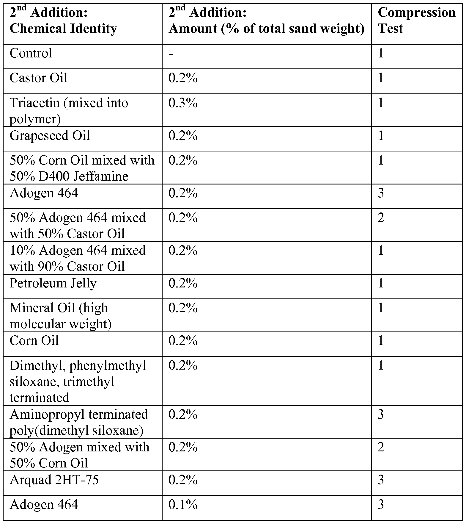
- Example 39 Oil-based Additives
- SSP Samples were prepared by mixing 300 g of 30/50 sand, preheated to 45 °C, with 9 g of a 10% glycerol/90% Flopam 533 mixture in a KitchenAid mixer at speed 1. After 1 minute of mixing, the second additive (usually at 0.2% by wt sand) was introduced and the mixture was mixed for another minute. The sample was dried under medium shear conditions using a heat gun and KitchenAid. The samples were then subjected to >50% RH in a humidity chamber for 1 hour. They were then individually tested for caking behavior by undergoing the compression test. This consisted of being compressed at 200 PSI for 30 seconds in a compression cell using a Carver Press, then removed from the cell and observed.
- the resulting cake (See Table 16, Compression Test) was graded on the following scale: “1 "-Solid cake that can be handled without falling apart, "2"-Mostly solid cake that begins to break as handled, "3 "-Cake is crumbly out of press cell, "4"-No cake formation, as set forth in Table 16.
Abstract
Description


Claims
Priority Applications (8)
| Application Number | Priority Date | Filing Date | Title |
|---|---|---|---|
| MX2014012609A MX2014012609A (en) | 2012-04-19 | 2013-03-15 | Self-suspending proppants for hydraulic fracturing. |
| CA2870730A CA2870730A1 (en) | 2012-04-19 | 2013-03-15 | Self-suspending proppants for hydraulic fracturing |
| EP13778228.0A EP2838973A4 (en) | 2012-04-19 | 2013-03-15 | Self-suspending proppants for hydraulic fracturing |
| CN201380030270.0A CN104379697A (en) | 2012-04-19 | 2013-03-15 | Self-suspending proppants for hydraulic fracturing |
| BR112014026038A BR112014026038A2 (en) | 2012-04-19 | 2013-03-15 | modified proppant, hydraulic fracturing formulation, well fracture method, production method of a modified proppant, and method of producing a hydrogel-coated proppant |
| AU2013249743A AU2013249743B2 (en) | 2012-04-19 | 2013-03-15 | Self-suspending proppants for hydraulic fracturing |
| HK15103786.5A HK1203212A1 (en) | 2012-04-19 | 2015-04-20 | Self-suspending proppants for hydraulic fracturing |
| AU2017200137A AU2017200137A1 (en) | 2011-08-31 | 2017-01-09 | Self-suspending proppants for hydraulic fracturing |
Applications Claiming Priority (8)
| Application Number | Priority Date | Filing Date | Title |
|---|---|---|---|
| US201261635612P | 2012-04-19 | 2012-04-19 | |
| US61/635,612 | 2012-04-19 | ||
| US201261662681P | 2012-06-21 | 2012-06-21 | |
| US61/662,681 | 2012-06-21 | ||
| US201261725751P | 2012-11-13 | 2012-11-13 | |
| US61/725,751 | 2012-11-13 | ||
| US201361764792P | 2013-02-14 | 2013-02-14 | |
| US61/764,792 | 2013-02-14 |
Publications (1)
| Publication Number | Publication Date |
|---|---|
| WO2013158308A1 true WO2013158308A1 (en) | 2013-10-24 |
Family
ID=49383940
Family Applications (2)
| Application Number | Title | Priority Date | Filing Date |
|---|---|---|---|
| PCT/US2013/032435 WO2013158308A1 (en) | 2011-08-31 | 2013-03-15 | Self-suspending proppants for hydraulic fracturing |
| PCT/US2013/032424 WO2013158306A1 (en) | 2012-04-19 | 2013-03-15 | Self-suspending proppants for hydraulic fracturing |
Family Applications After (1)
| Application Number | Title | Priority Date | Filing Date |
|---|---|---|---|
| PCT/US2013/032424 WO2013158306A1 (en) | 2012-04-19 | 2013-03-15 | Self-suspending proppants for hydraulic fracturing |
Country Status (9)
| Country | Link |
|---|---|
| EP (2) | EP2838973A4 (en) |
| CN (2) | CN104364343A (en) |
| AU (3) | AU2013249741A1 (en) |
| BR (2) | BR112014026041A2 (en) |
| CA (2) | CA2870730A1 (en) |
| HK (2) | HK1203212A1 (en) |
| MX (2) | MX2014012609A (en) |
| RU (1) | RU2621239C2 (en) |
| WO (2) | WO2013158308A1 (en) |
Cited By (19)
| Publication number | Priority date | Publication date | Assignee | Title |
|---|---|---|---|---|
| WO2014110121A1 (en) * | 2013-01-08 | 2014-07-17 | Cidra Corporate Services Inc. | Smart proppant technology for fracking and well production performance monitoring |
| CN104946233A (en) * | 2014-03-28 | 2015-09-30 | 北京仁创科技集团有限公司 | Self-suspension supporting agent for natural water fracturing |
| WO2015152755A1 (en) * | 2014-04-02 | 2015-10-08 | Шлюмберже Канада Лимитед | Propping agent and method for placing same in a hydraulic fracture |
| WO2015152756A1 (en) * | 2014-03-31 | 2015-10-08 | Шлюмберже Канада Лимитед | Method for modifying and delivering a propping agent during well operations |
| US20160032177A1 (en) * | 2014-07-31 | 2016-02-04 | Carbo Ceramics Inc. | Methods and systems for infusing porous ceramic proppant with a chemical treatment agent |
| US9429006B2 (en) | 2013-03-01 | 2016-08-30 | Baker Hughes Incorporated | Method of enhancing fracture conductivity |
| WO2016186621A1 (en) * | 2015-05-15 | 2016-11-24 | Halliburton Energy Services, Inc. | Multifunctional proppant for fracturing applications |
| CN106281298A (en) * | 2016-08-17 | 2017-01-04 | 常熟理工学院 | A kind of new method prepared from suspension haydite |
| WO2017052515A1 (en) * | 2015-09-22 | 2017-03-30 | Halliburton Energy Services, Inc. | Crosslinked polymer-coated proppant |
| US9840660B2 (en) | 2014-02-26 | 2017-12-12 | Halliburton Energy Services, Inc. | Crosslinker-coated proppant particulates for use in treatment fluids comprising gelling agents |
| CN108117662A (en) * | 2017-11-30 | 2018-06-05 | 中国科学院兰州化学物理研究所 | A kind of method for preparing hydrophilic lubrication coating in material surface |
| US10060570B2 (en) | 2013-01-09 | 2018-08-28 | Cidra Corporate Services, Inc. | Smart pipe concept based on embedded taggant-sensor and/or color-encoded elements to monitor liner wear in lined pipelines, including urethane lined pipe |
| US10066152B2 (en) | 2014-08-15 | 2018-09-04 | Halliburton Energy Services, Inc. | Crosslinkable proppant particulates for use in subterranean formation operations |
| RU2675705C1 (en) * | 2013-11-15 | 2018-12-24 | ДАУ ГЛОБАЛ ТЕКНОЛОДЖИЗ ЭлЭлСи | Proppant with improved dust control |
| WO2019005570A1 (en) * | 2017-06-29 | 2019-01-03 | Self-Suspending Proppant Llc | Improved self-suspending proppants made from powdered hydrogel-forming polymers |
| US10208243B2 (en) | 2015-03-12 | 2019-02-19 | Halliburton Energy Services, Inc. | Low-energy proppants for downhole operations |
| CN109535449A (en) * | 2018-12-05 | 2019-03-29 | 福州大学 | A kind of preparation method of the high tough chitosan-based hydrogel of high-low temperature resistant |
| CN113755154A (en) * | 2021-10-29 | 2021-12-07 | 江苏臻诚能源科技有限公司 | Preparation method of full-crack propping agent |
| US11713415B2 (en) | 2018-11-21 | 2023-08-01 | Covia Solutions Inc. | Salt-tolerant self-suspending proppants made without extrusion |
Families Citing this family (108)
| Publication number | Priority date | Publication date | Assignee | Title |
|---|---|---|---|---|
| CA2777748C (en) | 2009-10-20 | 2017-09-19 | Soane Energy Llc | Proppants for hydraulic fracturing technologies |
| US9290690B2 (en) | 2011-05-03 | 2016-03-22 | Preferred Technology, Llc | Coated and cured proppants |
| US8763700B2 (en) | 2011-09-02 | 2014-07-01 | Robert Ray McDaniel | Dual function proppants |
| US9725645B2 (en) | 2011-05-03 | 2017-08-08 | Preferred Technology, Llc | Proppant with composite coating |
| US9868896B2 (en) | 2011-08-31 | 2018-01-16 | Self-Suspending Proppant Llc | Self-suspending proppants for hydraulic fracturing |
| RU2602250C2 (en) | 2011-08-31 | 2016-11-10 | Селф-Саспендинг Проппант Ллс | Self-suspending proppants for hydraulic fracturing |
| US20140000891A1 (en) | 2012-06-21 | 2014-01-02 | Self-Suspending Proppant Llc | Self-suspending proppants for hydraulic fracturing |
| US9297244B2 (en) | 2011-08-31 | 2016-03-29 | Self-Suspending Proppant Llc | Self-suspending proppants for hydraulic fracturing comprising a coating of hydrogel-forming polymer |
| US9562187B2 (en) | 2012-01-23 | 2017-02-07 | Preferred Technology, Llc | Manufacture of polymer coated proppants |
| CA2870730A1 (en) * | 2012-04-19 | 2013-10-24 | Self-Suspending Proppant Llc | Self-suspending proppants for hydraulic fracturing |
| US9518214B2 (en) | 2013-03-15 | 2016-12-13 | Preferred Technology, Llc | Proppant with polyurea-type coating |
| US10100247B2 (en) | 2013-05-17 | 2018-10-16 | Preferred Technology, Llc | Proppant with enhanced interparticle bonding |
| US9932521B2 (en) | 2014-03-05 | 2018-04-03 | Self-Suspending Proppant, Llc | Calcium ion tolerant self-suspending proppants |
| US20150252252A1 (en) * | 2014-03-05 | 2015-09-10 | Self-Suspending Proppant Llc | Humidity-resistant self-suspending proppants |
| CN104946235A (en) * | 2014-03-28 | 2015-09-30 | 北京仁创科技集团有限公司 | Preparation method of self-suspension proppant and prepared proppant |
| WO2015148836A1 (en) | 2014-03-28 | 2015-10-01 | Arr-Maz Products, L.P. | Attrition resistant proppant composite and its composition matters |
| US10508231B2 (en) | 2014-03-28 | 2019-12-17 | Arr-Maz Products, L.P. | Attrition resistant proppant composite and its composition matters |
| EP3124741A4 (en) * | 2014-03-28 | 2017-04-19 | Beijing Rechsand Science&Technology Group Co. Ltd | Self-suspending proppant and preparation and use thereof |
| NO340788B1 (en) * | 2014-09-17 | 2017-06-19 | Wellcem Innovation As | Improved method and chemical agent for reducing water production from oil and gas-containing wells |
| US9862878B2 (en) | 2014-12-11 | 2018-01-09 | Saudi Arabian Oil Company | High temperature fracturing fluids with nano-crosslinkers |
| US11268016B2 (en) | 2014-12-11 | 2022-03-08 | Saudi Arabian Oil Company | High temperature treatment fluids with nano-crosslinkers |
| MX2017008358A (en) * | 2015-01-23 | 2017-10-26 | Preferred Tech Llc | Proppant solids with water absorbent materials and methods of making the same. |
| CN107532078A (en) * | 2015-04-08 | 2018-01-02 | 自悬浮支撑有限公司 | Resistance to hard water and salt solution from suspended prop |
| US9862881B2 (en) | 2015-05-13 | 2018-01-09 | Preferred Technology, Llc | Hydrophobic coating of particulates for enhanced well productivity |
| WO2016183313A1 (en) | 2015-05-13 | 2016-11-17 | Preferred Technology, Llc | High performance proppants |
| CN104893707B (en) * | 2015-05-22 | 2018-09-21 | 河南天祥新材料股份有限公司 | It is a kind of for riverfrac treatment from suspended prop and preparation method thereof |
| CN112920782A (en) * | 2015-07-13 | 2021-06-08 | 沙特阿拉伯石油公司 | Stabilized nanoparticle compositions comprising ions |
| CN106928984A (en) * | 2015-12-30 | 2017-07-07 | 北京仁创科技集团有限公司 | Expanding material composition containing polyvinyl alcohol and from suspended prop and its preparation method and application |
| CN106928976A (en) * | 2015-12-30 | 2017-07-07 | 北京仁创科技集团有限公司 | Expanding material composition containing polyethylene glycol and from suspended prop and its application and preparation method |
| CN106928967A (en) * | 2015-12-30 | 2017-07-07 | 北京仁创科技集团有限公司 | Expanding material composition containing polyethylene glycol and from suspended prop and its preparation method and application |
| CN106928978A (en) * | 2015-12-30 | 2017-07-07 | 北京仁创科技集团有限公司 | Expanding material composition containing polyethylene glycol oxide and from suspended prop and its preparation method and application |
| CN106928987A (en) * | 2015-12-30 | 2017-07-07 | 北京仁创科技集团有限公司 | Expanding material composition containing polyvinylpyrrolidone and from suspended prop and its application and preparation method |
| CN106928983A (en) * | 2015-12-30 | 2017-07-07 | 北京仁创科技集团有限公司 | Expanding material composition containing polyvinylpyrrolidone and from suspended prop and the preparation method and application of proppant |
| CN106928980A (en) * | 2015-12-30 | 2017-07-07 | 北京仁创科技集团有限公司 | Expanding material composition containing polyvinyl alcohol and from suspended prop and its application and preparation method |
| CN106928985A (en) * | 2015-12-30 | 2017-07-07 | 北京仁创科技集团有限公司 | Expanding material composition containing polyethylene glycol oxide and the application from suspended prop and proppant and preparation method |
| CN106928989A (en) * | 2015-12-30 | 2017-07-07 | 北京仁创科技集团有限公司 | Expanding material composition containing polyacrylic acid and from suspended prop and its preparation method and application |
| CN106928968A (en) * | 2015-12-30 | 2017-07-07 | 北京仁创科技集团有限公司 | Expanding material composition containing polyethylene glycol and the application from suspended prop and proppant and preparation method |
| CN106928964A (en) * | 2015-12-30 | 2017-07-07 | 北京仁创科技集团有限公司 | Expanding material composition containing polyacrylamide and the application from suspended prop and proppant and preparation method |
| CN106928971A (en) * | 2015-12-30 | 2017-07-07 | 北京仁创科技集团有限公司 | Expanding material composition containing polyacrylamide and from suspended prop and its preparation method and application |
| CN106928970A (en) * | 2015-12-30 | 2017-07-07 | 北京仁创科技集团有限公司 | Expanding material composition containing polyvinylpyrrolidone and the application from suspended prop and proppant and preparation method |
| CN106928972A (en) * | 2015-12-30 | 2017-07-07 | 北京仁创科技集团有限公司 | Expanding material composition containing HPMA and the application from suspended prop and proppant and preparation method |
| CN106928961A (en) * | 2015-12-30 | 2017-07-07 | 北京仁创科技集团有限公司 | Expanding material composition containing polyvinylpyrrolidone and from suspended prop and its preparation method and application |
| CN106928977A (en) * | 2015-12-30 | 2017-07-07 | 北京仁创科技集团有限公司 | Expanding material composition containing natural macromolecular material and from suspended prop and its preparation method and application |
| CN106928981A (en) * | 2015-12-30 | 2017-07-07 | 北京仁创科技集团有限公司 | Expanding material composition containing HPMA and from suspended prop and its application and preparation method |
| CN106928988A (en) * | 2015-12-30 | 2017-07-07 | 北京仁创科技集团有限公司 | Expanding material composition containing polyvinylpyrrolidone and from suspended prop and its preparation method and application |
| CN106928966A (en) * | 2015-12-30 | 2017-07-07 | 北京仁创科技集团有限公司 | Expanding material composition containing polyvinyl alcohol and the application from suspended prop and proppant and preparation method |
| CN106928969A (en) * | 2015-12-30 | 2017-07-07 | 北京仁创科技集团有限公司 | Expanding material composition containing HPMA and from suspended prop and the preparation method and application of proppant |
| CN106928962A (en) * | 2015-12-30 | 2017-07-07 | 北京仁创科技集团有限公司 | Expanding material composition containing polyethylene glycol and from suspended prop and the preparation method and application of proppant |
| CN106928965A (en) * | 2015-12-30 | 2017-07-07 | 北京仁创科技集团有限公司 | Expanding material composition containing polyacrylic acid and the application from suspended prop and proppant and preparation method |
| CN106928986A (en) * | 2015-12-30 | 2017-07-07 | 北京仁创科技集团有限公司 | Expanding material composition containing polyethylene glycol oxide and from suspended prop and its application and preparation method |
| CN106928973A (en) * | 2015-12-30 | 2017-07-07 | 北京仁创科技集团有限公司 | Water-soluble expanding material composition and from suspended prop and preparation method and application |
| CN106928991A (en) * | 2015-12-30 | 2017-07-07 | 北京仁创科技集团有限公司 | Expanding material composition containing polyethylene glycol and the application from suspended prop and proppant and preparation method |
| CN106928975A (en) * | 2015-12-30 | 2017-07-07 | 北京仁创科技集团有限公司 | Expanding material composition containing polyethylene glycol oxide and from suspended prop and its preparation method and application |
| CN106928982A (en) * | 2015-12-30 | 2017-07-07 | 北京仁创科技集团有限公司 | Expanding material composition containing polyacrylic acid and from suspended prop and the preparation method and application of proppant |
| CN106928963A (en) * | 2015-12-30 | 2017-07-07 | 北京仁创科技集团有限公司 | Expanding material composition containing polyvinyl alcohol and from suspended prop and the preparation method and application of proppant |
| CN106928990A (en) * | 2015-12-30 | 2017-07-07 | 北京仁创科技集团有限公司 | Expanding material composition and from suspended prop and preparation method and application |
| CN106928979A (en) * | 2015-12-30 | 2017-07-07 | 北京仁创科技集团有限公司 | Expanding material composition containing polyacrylic acid and from suspended prop and its application and preparation method |
| CN106928993A (en) * | 2015-12-30 | 2017-07-07 | 北京仁创科技集团有限公司 | Expanding material composition containing polyethylene glycol oxide and from suspended prop and the preparation method and application of proppant |
| CN106928992A (en) * | 2015-12-30 | 2017-07-07 | 北京仁创科技集团有限公司 | Expanding material composition containing natural macromolecular material and from suspended prop and preparation method and application |
| CN106928974A (en) * | 2015-12-30 | 2017-07-07 | 北京仁创科技集团有限公司 | Expanding material composition containing polyvinyl alcohol and the application from suspended prop and proppant and preparation method |
| CN106947438A (en) * | 2016-01-07 | 2017-07-14 | 中国石油化工股份有限公司 | A kind of drilling fluid aluminium base inhibitor and preparation method thereof |
| CN105670600A (en) * | 2016-03-07 | 2016-06-15 | 王展旭 | Water acid-sensitivity deformation magnetic tracer function self-suspension propping agent and preparation method thereof |
| CN105754580B (en) * | 2016-03-25 | 2018-09-11 | 山东诺尔生物科技有限公司 | Pressure break is with low frictional resistance from the preparation method of suspended prop |
| CN105670597A (en) * | 2016-04-21 | 2016-06-15 | 成都劳恩普斯科技有限公司 | Method for preventing proppants in water-base fracturing fluid from settling in transfer process |
| US20170335178A1 (en) * | 2016-05-17 | 2017-11-23 | Self-Suspending LLC | Salt-tolerant self-suspending proppants |
| CN107459987A (en) * | 2016-06-03 | 2017-12-12 | 中国石油化工股份有限公司 | It is a kind of from suspension volume expansion type proppant and preparation method thereof |
| CN107459986A (en) * | 2016-06-03 | 2017-12-12 | 中国石油化工股份有限公司 | It is a kind of from suspended prop and preparation method thereof |
| CN106186829B (en) * | 2016-06-29 | 2017-12-08 | 河南祥泰科技有限公司 | The solid integrated petroleum propping agent of liquid |
| CN106147746B (en) * | 2016-07-07 | 2021-03-02 | 新密市万力实业发展有限公司 | Self-suspending proppant applied to clean water fracturing system |
| US10457860B2 (en) * | 2016-10-05 | 2019-10-29 | S.P.C.M. Sa | Self suspending proppants with brine tolerance for hydraulic fracturing |
| US20180118972A1 (en) * | 2016-11-02 | 2018-05-03 | Covestro Llc | Reducing erosion of oil field pumping and transfer equipment |
| US11208591B2 (en) | 2016-11-16 | 2021-12-28 | Preferred Technology, Llc | Hydrophobic coating of particulates for enhanced well productivity |
| CN106526137A (en) * | 2016-11-17 | 2017-03-22 | 青岛科技大学 | Physical simulation experiment evaluation method for fracturing performance and flow conductivity of self-suspension propping agent |
| CN106675548A (en) * | 2016-11-25 | 2017-05-17 | 北京昆仑隆源石油开采技术有限公司 | Self-suspension propping agent and preparation method thereof |
| US10696896B2 (en) | 2016-11-28 | 2020-06-30 | Prefferred Technology, Llc | Durable coatings and uses thereof |
| CN106675549B (en) * | 2016-12-05 | 2021-11-09 | 北京奇想达新材料有限公司 | Underwater suspensible proppant for oil-gas well fracturing and preparation method thereof |
| CN106833599A (en) * | 2016-12-28 | 2017-06-13 | 北京晨础石油科技有限公司 | Exempt from liquid proppant and preparation method thereof |
| US10131832B2 (en) * | 2017-02-13 | 2018-11-20 | Aramco Services Company | Self-suspending proppants for use in carbon dioxide-based fracturing fluids and methods of making and use thereof |
| CN106928939A (en) * | 2017-02-14 | 2017-07-07 | 中国石油集团西部钻探工程有限公司 | Leak stopping synergist and preparation method thereof and application method |
| CA3055302A1 (en) * | 2017-03-20 | 2018-09-27 | Fairmount Santrol Inc. | Flowback resistant proppants |
| CN108795404B (en) * | 2017-04-27 | 2021-09-28 | 关中原 | Self-suspending proppant for clean water fracturing and preparation method thereof |
| CN107033871B (en) * | 2017-06-08 | 2018-08-07 | 广汉市华星新技术开发研究所(普通合伙) | One kind is from suspended prop and preparation method thereof |
| CN109536158B (en) * | 2017-09-21 | 2021-11-26 | 中国石油化工股份有限公司 | Low-density ceramsite proppant and preparation method thereof |
| US11591505B2 (en) | 2017-10-16 | 2023-02-28 | Terves, Llc | High density fluid for completion applications |
| WO2019079144A1 (en) | 2017-10-16 | 2019-04-25 | Terves Inc. | Non-toxic high density fluid for completion applications |
| CN108191307B (en) * | 2017-12-25 | 2020-10-09 | 厦门市固力克节能科技有限公司 | Anti-drop graphene stone-like paint and preparation method thereof |
| CN109971455A (en) * | 2017-12-28 | 2019-07-05 | 中国石油化工股份有限公司 | A kind of forming method of high-speed channel pressure break self aggregation proppant column |
| CN108517205B (en) * | 2018-05-16 | 2020-07-28 | 重庆长江造型材料(集团)股份有限公司 | Low-friction composite nano proppant and preparation method thereof |
| CN108841372A (en) * | 2018-07-04 | 2018-11-20 | 中国石油集团渤海钻探工程有限公司 | Water-absorbing resins overlay film is from suspended prop and preparation method thereof |
| CN109180966A (en) * | 2018-08-30 | 2019-01-11 | 国悦环境工程技术服务(北京)有限公司 | It is a kind of with improve water-soluble polymer powder hydration rate and in the unit time suspension of viscosity preparation method |
| CN109337668A (en) * | 2018-09-30 | 2019-02-15 | 重庆长江造型材料(集团)股份有限公司 | One kind is from suspension covering material |
| CN108949140A (en) * | 2018-09-30 | 2018-12-07 | 重庆长江造型材料(集团)股份有限公司 | One kind is from suspension type support agent |
| CN109749731B (en) * | 2019-01-14 | 2021-09-07 | 重庆长江造型材料(集团)股份有限公司 | Preparation method of tectorial membrane proppant for fracturing |
| CN109575909A (en) * | 2019-01-14 | 2019-04-05 | 重庆长江造型材料(集团)股份有限公司 | A kind of pressure break overlay film proppant |
| CN109777394B (en) * | 2019-02-28 | 2021-09-21 | 东北石油大学 | Preparation method of self-suspending self-degrading proppant |
| CN110358523A (en) * | 2019-06-27 | 2019-10-22 | 海油来博(天津)科技股份有限公司 | A kind of specialty polymer and its application for from suspended prop |
| CA3145064A1 (en) | 2019-07-31 | 2021-02-04 | Praveen AGARWAL | Coated proppants |
| CN110454120B (en) * | 2019-08-13 | 2021-10-01 | 青岛大地新能源技术研究院 | Construction method for self-gathering sand prevention of oil-water well |
| CN111286318A (en) * | 2020-04-07 | 2020-06-16 | 赣江新区澳博颗粒科技研究院有限公司 | Self-generated bubble suspension proppant for fracturing and construction method thereof |
| CN111880232B (en) * | 2020-07-06 | 2023-06-30 | 中国石油天然气股份有限公司 | Magnetic nano-film imaging propping agent and preparation method and application thereof |
| CN112300774B (en) * | 2020-09-02 | 2022-04-22 | 西南石油大学 | Preparation method of water-controlled oxidation gel-breaking self-suspension proppant for fracturing |
| CN111961460B (en) * | 2020-09-22 | 2021-08-03 | 西南石油大学 | High-efficiency energy-saving bridge channel fully-coupled fiber proppant system and application method thereof |
| CN112479696A (en) * | 2020-11-13 | 2021-03-12 | 四川海沃石油工程技术有限公司 | Production principle and process of special fracturing propping agent with strong compressive capacity |
| CN114836192B (en) * | 2021-06-25 | 2024-01-05 | 四川银宇化工科技有限公司 | Self-suspension propping agent and preparation method and application thereof |
| CN114233262B (en) * | 2021-12-27 | 2023-10-27 | 西安石油大学 | Method for supporting unconsolidated hydrate reservoir fracture with assistance of modified hydrogel |
| CN114988753B (en) * | 2022-04-28 | 2022-11-25 | 广东建盛高新材料有限公司 | Machine-made sand regulator and preparation method thereof |
| CN114989793B (en) * | 2022-07-22 | 2024-03-22 | 中国石油大学(华东) | Oil-based drilling fluid system capable of self-removing nano-micron inferior solid phase, and preparation method and application thereof |
| CN115324553B (en) * | 2022-10-13 | 2022-12-13 | 西安博探石油工程有限公司 | Nano miscible imbibition oil displacement self-crosslinking fracturing method |
Citations (7)
| Publication number | Priority date | Publication date | Assignee | Title |
|---|---|---|---|---|
| US20040244978A1 (en) * | 2003-06-04 | 2004-12-09 | Sun Drilling Products Corporation | Lost circulation material blend offering high fluid loss with minimum solids |
| US20050274510A1 (en) * | 2004-06-15 | 2005-12-15 | Nguyen Philip D | Electroconductive proppant compositions and related methods |
| US7135231B1 (en) * | 2003-07-01 | 2006-11-14 | Fairmont Minerals, Ltd. | Process for incremental coating of proppants for hydraulic fracturing and proppants produced therefrom |
| US20080108524A1 (en) * | 2006-11-08 | 2008-05-08 | Willberg Dean M | Delayed Water-Swelling Materials and Methods of Use |
| US20080289828A1 (en) * | 2006-09-18 | 2008-11-27 | Hutchins Richard D | Methods of Limiting Leak Off and Damage In Hydraulic Fractures |
| US20100249273A1 (en) * | 2009-03-31 | 2010-09-30 | Scales Charles W | Polymeric articles comprising oxygen permeability enhancing particles |
| US20110120719A1 (en) * | 2009-10-20 | 2011-05-26 | David Soane | Proppants for hydraulic fracturing technologies |
Family Cites Families (10)
| Publication number | Priority date | Publication date | Assignee | Title |
|---|---|---|---|---|
| US2008A (en) * | 1841-03-18 | Gas-lamp eok conducting gas pkom ah elevated buhner to one below it | ||
| US6109350A (en) * | 1998-01-30 | 2000-08-29 | Halliburton Energy Services, Inc. | Method of reducing water produced with hydrocarbons from wells |
| US7131491B2 (en) * | 2004-06-09 | 2006-11-07 | Halliburton Energy Services, Inc. | Aqueous-based tackifier fluids and methods of use |
| CN1894284B (en) * | 2003-12-15 | 2011-01-05 | 赫尔克里士公司 | Improved inversion of inverse emulsion polymers |
| US7244492B2 (en) * | 2004-03-04 | 2007-07-17 | Fairmount Minerals, Ltd. | Soluble fibers for use in resin coated proppant |
| GB2436576B (en) * | 2006-03-28 | 2008-06-18 | Schlumberger Holdings | Method of facturing a coalbed gas reservoir |
| US9303502B2 (en) * | 2009-10-27 | 2016-04-05 | Baker Hughes Incorporated | Method of controlling water production through treating particles with RPMS |
| MX336826B (en) * | 2009-10-26 | 2016-02-03 | Hexion Specialty Chemicals Inc | Low temperature coated particles for use as proppants or in gravel packs, methods for making and using the same. |
| CA2799374C (en) * | 2010-05-17 | 2018-07-31 | Georgia-Pacific Chemicals Llc | Proppants for use in hydraulic fracturing of subterranean formations |
| CA2870730A1 (en) * | 2012-04-19 | 2013-10-24 | Self-Suspending Proppant Llc | Self-suspending proppants for hydraulic fracturing |
-
2013
- 2013-03-15 CA CA2870730A patent/CA2870730A1/en not_active Abandoned
- 2013-03-15 AU AU2013249741A patent/AU2013249741A1/en not_active Abandoned
- 2013-03-15 MX MX2014012609A patent/MX2014012609A/en unknown
- 2013-03-15 CA CA2870726A patent/CA2870726A1/en not_active Abandoned
- 2013-03-15 CN CN201380030233.XA patent/CN104364343A/en active Pending
- 2013-03-15 BR BR112014026041A patent/BR112014026041A2/en not_active IP Right Cessation
- 2013-03-15 MX MX2014012610A patent/MX2014012610A/en unknown
- 2013-03-15 EP EP13778228.0A patent/EP2838973A4/en not_active Withdrawn
- 2013-03-15 EP EP13778014.4A patent/EP2838972A4/en not_active Withdrawn
- 2013-03-15 BR BR112014026038A patent/BR112014026038A2/en not_active Application Discontinuation
- 2013-03-15 WO PCT/US2013/032435 patent/WO2013158308A1/en active Application Filing
- 2013-03-15 AU AU2013249743A patent/AU2013249743B2/en not_active Ceased
- 2013-03-15 RU RU2014145131A patent/RU2621239C2/en not_active IP Right Cessation
- 2013-03-15 WO PCT/US2013/032424 patent/WO2013158306A1/en active Application Filing
- 2013-03-15 CN CN201380030270.0A patent/CN104379697A/en active Pending
-
2015
- 2015-04-20 HK HK15103786.5A patent/HK1203212A1/en unknown
- 2015-04-20 HK HK15103787.4A patent/HK1203213A1/en unknown
-
2017
- 2017-01-09 AU AU2017200137A patent/AU2017200137A1/en not_active Abandoned
Patent Citations (7)
| Publication number | Priority date | Publication date | Assignee | Title |
|---|---|---|---|---|
| US20040244978A1 (en) * | 2003-06-04 | 2004-12-09 | Sun Drilling Products Corporation | Lost circulation material blend offering high fluid loss with minimum solids |
| US7135231B1 (en) * | 2003-07-01 | 2006-11-14 | Fairmont Minerals, Ltd. | Process for incremental coating of proppants for hydraulic fracturing and proppants produced therefrom |
| US20050274510A1 (en) * | 2004-06-15 | 2005-12-15 | Nguyen Philip D | Electroconductive proppant compositions and related methods |
| US20080289828A1 (en) * | 2006-09-18 | 2008-11-27 | Hutchins Richard D | Methods of Limiting Leak Off and Damage In Hydraulic Fractures |
| US20080108524A1 (en) * | 2006-11-08 | 2008-05-08 | Willberg Dean M | Delayed Water-Swelling Materials and Methods of Use |
| US20100249273A1 (en) * | 2009-03-31 | 2010-09-30 | Scales Charles W | Polymeric articles comprising oxygen permeability enhancing particles |
| US20110120719A1 (en) * | 2009-10-20 | 2011-05-26 | David Soane | Proppants for hydraulic fracturing technologies |
Non-Patent Citations (1)
| Title |
|---|
| See also references of EP2838973A4 * |
Cited By (34)
| Publication number | Priority date | Publication date | Assignee | Title |
|---|---|---|---|---|
| US11866646B2 (en) | 2013-01-08 | 2024-01-09 | Cidra Corporate Services Inc. | Smart proppant technology for fracking and well production performance monitoring |
| US11773317B2 (en) | 2013-01-08 | 2023-10-03 | Cidra Corporate Services Inc. | Smart proppant technology for fracking and well production performance monitoring |
| WO2014110121A1 (en) * | 2013-01-08 | 2014-07-17 | Cidra Corporate Services Inc. | Smart proppant technology for fracking and well production performance monitoring |
| US10060570B2 (en) | 2013-01-09 | 2018-08-28 | Cidra Corporate Services, Inc. | Smart pipe concept based on embedded taggant-sensor and/or color-encoded elements to monitor liner wear in lined pipelines, including urethane lined pipe |
| US9429006B2 (en) | 2013-03-01 | 2016-08-30 | Baker Hughes Incorporated | Method of enhancing fracture conductivity |
| US11104842B2 (en) | 2013-11-15 | 2021-08-31 | Dow Global Technologies Llc | Proppants with improved dust control |
| RU2675705C1 (en) * | 2013-11-15 | 2018-12-24 | ДАУ ГЛОБАЛ ТЕКНОЛОДЖИЗ ЭлЭлСи | Proppant with improved dust control |
| US9840660B2 (en) | 2014-02-26 | 2017-12-12 | Halliburton Energy Services, Inc. | Crosslinker-coated proppant particulates for use in treatment fluids comprising gelling agents |
| CN104946233A (en) * | 2014-03-28 | 2015-09-30 | 北京仁创科技集团有限公司 | Self-suspension supporting agent for natural water fracturing |
| CN104946233B (en) * | 2014-03-28 | 2018-12-04 | 北京仁创科技集团有限公司 | It is a kind of for natural water pressure break from suspended prop |
| US10351761B2 (en) | 2014-03-31 | 2019-07-16 | Schlumberger Technology Corporation | Method for modification and delivery of proppant during well operations, method for hydraulic fracturing and method for gravel packing |
| GB2540063A (en) * | 2014-03-31 | 2017-01-04 | Schlumberger Holdings | Method for modifying and delivering a propping agent during well operations |
| WO2015152756A1 (en) * | 2014-03-31 | 2015-10-08 | Шлюмберже Канада Лимитед | Method for modifying and delivering a propping agent during well operations |
| WO2015152755A1 (en) * | 2014-04-02 | 2015-10-08 | Шлюмберже Канада Лимитед | Propping agent and method for placing same in a hydraulic fracture |
| CN106661442A (en) * | 2014-04-02 | 2017-05-10 | 普拉德研究及开发股份有限公司 | Propping agent and method for placing same in a hydraulic fracture |
| EA034457B1 (en) * | 2014-07-31 | 2020-02-11 | Карбо Керамикс, Инк. | Methods and systems for infusing porous ceramic proppant with a chemical treatment agent |
| US11015112B2 (en) | 2014-07-31 | 2021-05-25 | Carbo Ceramics Inc | Methods and systems for infusing porous ceramic proppant with a chemical treatment agent |
| CN106795752A (en) * | 2014-07-31 | 2017-05-31 | 卡博陶粒有限公司 | The method and system of porous ceramic support agent is injected with chemical treatments |
| US20160032177A1 (en) * | 2014-07-31 | 2016-02-04 | Carbo Ceramics Inc. | Methods and systems for infusing porous ceramic proppant with a chemical treatment agent |
| US9994764B2 (en) | 2014-07-31 | 2018-06-12 | Carbo Ceramics Inc. | Methods and systems for infusing porous ceramic proppant with a chemical treatment agent |
| CN106795752B (en) * | 2014-07-31 | 2020-08-18 | 卡博陶粒有限公司 | Method and system for injecting porous ceramic proppant with chemical treatment agent |
| WO2016019101A1 (en) * | 2014-07-31 | 2016-02-04 | Carbo Ceramics Inc. | Methods and systems for infusing porous ceramic proppant with a chemical treatment agent |
| US10066152B2 (en) | 2014-08-15 | 2018-09-04 | Halliburton Energy Services, Inc. | Crosslinkable proppant particulates for use in subterranean formation operations |
| US10208243B2 (en) | 2015-03-12 | 2019-02-19 | Halliburton Energy Services, Inc. | Low-energy proppants for downhole operations |
| US10259991B2 (en) | 2015-05-15 | 2019-04-16 | Halliburton Energy Services, Inc. | Multifunctional proppant for fracturing applications |
| WO2016186621A1 (en) * | 2015-05-15 | 2016-11-24 | Halliburton Energy Services, Inc. | Multifunctional proppant for fracturing applications |
| US10400160B2 (en) | 2015-09-22 | 2019-09-03 | Halliburton Energy Services, Inc. | Crosslinked polymer-coated proppant |
| WO2017052515A1 (en) * | 2015-09-22 | 2017-03-30 | Halliburton Energy Services, Inc. | Crosslinked polymer-coated proppant |
| CN106281298A (en) * | 2016-08-17 | 2017-01-04 | 常熟理工学院 | A kind of new method prepared from suspension haydite |
| WO2019005570A1 (en) * | 2017-06-29 | 2019-01-03 | Self-Suspending Proppant Llc | Improved self-suspending proppants made from powdered hydrogel-forming polymers |
| CN108117662A (en) * | 2017-11-30 | 2018-06-05 | 中国科学院兰州化学物理研究所 | A kind of method for preparing hydrophilic lubrication coating in material surface |
| US11713415B2 (en) | 2018-11-21 | 2023-08-01 | Covia Solutions Inc. | Salt-tolerant self-suspending proppants made without extrusion |
| CN109535449A (en) * | 2018-12-05 | 2019-03-29 | 福州大学 | A kind of preparation method of the high tough chitosan-based hydrogel of high-low temperature resistant |
| CN113755154A (en) * | 2021-10-29 | 2021-12-07 | 江苏臻诚能源科技有限公司 | Preparation method of full-crack propping agent |
Also Published As
| Publication number | Publication date |
|---|---|
| RU2621239C2 (en) | 2017-06-01 |
| RU2014145131A (en) | 2016-06-10 |
| EP2838973A4 (en) | 2016-03-02 |
| EP2838972A4 (en) | 2015-12-23 |
| HK1203213A1 (en) | 2015-10-23 |
| AU2013249743A1 (en) | 2014-11-06 |
| AU2013249741A1 (en) | 2014-11-06 |
| CA2870726A1 (en) | 2013-10-24 |
| HK1203212A1 (en) | 2015-10-23 |
| CA2870730A1 (en) | 2013-10-24 |
| WO2013158306A1 (en) | 2013-10-24 |
| BR112014026041A2 (en) | 2017-06-27 |
| AU2013249743B2 (en) | 2016-12-22 |
| EP2838972A1 (en) | 2015-02-25 |
| CN104379697A (en) | 2015-02-25 |
| AU2017200137A1 (en) | 2017-02-02 |
| MX2014012610A (en) | 2015-04-08 |
| BR112014026038A2 (en) | 2017-06-27 |
| EP2838973A1 (en) | 2015-02-25 |
| CN104364343A (en) | 2015-02-18 |
| MX2014012609A (en) | 2015-01-19 |
Similar Documents
| Publication | Publication Date | Title |
|---|---|---|
| AU2013249743B2 (en) | Self-suspending proppants for hydraulic fracturing | |
| US10472943B2 (en) | Self-suspending proppants for hydraulic fracturing | |
| US9644139B2 (en) | Self-suspending proppants for hydraulic fracturing | |
| US9868896B2 (en) | Self-suspending proppants for hydraulic fracturing | |
| US20140014348A1 (en) | Self-suspending proppants for hydraulic fracturing | |
| US10316244B2 (en) | Self-suspending proppants for hydraulic fracturing | |
| WO2013192634A2 (en) | Self-suspending proppants for hydraulic fracturing | |
| EP3114310A1 (en) | Humidity-resistant self-suspending proppants | |
| TW201827560A (en) | Self-suspending proppants for hydraulic fracturing |
Legal Events
| Date | Code | Title | Description |
|---|---|---|---|
| 121 | Ep: the epo has been informed by wipo that ep was designated in this application |
Ref document number: 13778228 Country of ref document: EP Kind code of ref document: A1 |
|
| ENP | Entry into the national phase |
Ref document number: 2870730 Country of ref document: CA |
|
| WWE | Wipo information: entry into national phase |
Ref document number: MX/A/2014/012609 Country of ref document: MX |
|
| NENP | Non-entry into the national phase |
Ref country code: DE |
|
| ENP | Entry into the national phase |
Ref document number: 2013249743 Country of ref document: AU Date of ref document: 20130315 Kind code of ref document: A |
|
| WWE | Wipo information: entry into national phase |
Ref document number: 2013778228 Country of ref document: EP |
|
| ENP | Entry into the national phase |
Ref document number: 2014145132 Country of ref document: RU Kind code of ref document: A |
|
| REG | Reference to national code |
Ref country code: BR Ref legal event code: B01A Ref document number: 112014026038 Country of ref document: BR |
|
| ENP | Entry into the national phase |
Ref document number: 112014026038 Country of ref document: BR Kind code of ref document: A2 Effective date: 20141017 |