WO2014002835A1 - Method for concentrating processing waste liquid and method for recycling processing waste liquid - Google Patents
Method for concentrating processing waste liquid and method for recycling processing waste liquid Download PDFInfo
- Publication number
- WO2014002835A1 WO2014002835A1 PCT/JP2013/066758 JP2013066758W WO2014002835A1 WO 2014002835 A1 WO2014002835 A1 WO 2014002835A1 JP 2013066758 W JP2013066758 W JP 2013066758W WO 2014002835 A1 WO2014002835 A1 WO 2014002835A1
- Authority
- WO
- WIPO (PCT)
- Prior art keywords
- group
- mass
- waste liquid
- lithographic printing
- general formula
- Prior art date
Links
Images
Classifications
-
- G—PHYSICS
- G03—PHOTOGRAPHY; CINEMATOGRAPHY; ANALOGOUS TECHNIQUES USING WAVES OTHER THAN OPTICAL WAVES; ELECTROGRAPHY; HOLOGRAPHY
- G03F—PHOTOMECHANICAL PRODUCTION OF TEXTURED OR PATTERNED SURFACES, e.g. FOR PRINTING, FOR PROCESSING OF SEMICONDUCTOR DEVICES; MATERIALS THEREFOR; ORIGINALS THEREFOR; APPARATUS SPECIALLY ADAPTED THEREFOR
- G03F7/00—Photomechanical, e.g. photolithographic, production of textured or patterned surfaces, e.g. printing surfaces; Materials therefor, e.g. comprising photoresists; Apparatus specially adapted therefor
- G03F7/26—Processing photosensitive materials; Apparatus therefor
- G03F7/30—Imagewise removal using liquid means
- G03F7/3092—Recovery of material; Waste processing
-
- B—PERFORMING OPERATIONS; TRANSPORTING
- B41—PRINTING; LINING MACHINES; TYPEWRITERS; STAMPS
- B41C—PROCESSES FOR THE MANUFACTURE OR REPRODUCTION OF PRINTING SURFACES
- B41C1/00—Forme preparation
- B41C1/10—Forme preparation for lithographic printing; Master sheets for transferring a lithographic image to the forme
- B41C1/1008—Forme preparation for lithographic printing; Master sheets for transferring a lithographic image to the forme by removal or destruction of lithographic material on the lithographic support, e.g. by laser or spark ablation; by the use of materials rendered soluble or insoluble by heat exposure, e.g. by heat produced from a light to heat transforming system; by on-the-press exposure or on-the-press development, e.g. by the fountain of photolithographic materials
- B41C1/1016—Forme preparation for lithographic printing; Master sheets for transferring a lithographic image to the forme by removal or destruction of lithographic material on the lithographic support, e.g. by laser or spark ablation; by the use of materials rendered soluble or insoluble by heat exposure, e.g. by heat produced from a light to heat transforming system; by on-the-press exposure or on-the-press development, e.g. by the fountain of photolithographic materials characterised by structural details, e.g. protective layers, backcoat layers or several imaging layers
-
- C—CHEMISTRY; METALLURGY
- C02—TREATMENT OF WATER, WASTE WATER, SEWAGE, OR SLUDGE
- C02F—TREATMENT OF WATER, WASTE WATER, SEWAGE, OR SLUDGE
- C02F1/00—Treatment of water, waste water, or sewage
- C02F1/02—Treatment of water, waste water, or sewage by heating
- C02F1/04—Treatment of water, waste water, or sewage by heating by distillation or evaporation
- C02F1/048—Purification of waste water by evaporation
-
- G—PHYSICS
- G03—PHOTOGRAPHY; CINEMATOGRAPHY; ANALOGOUS TECHNIQUES USING WAVES OTHER THAN OPTICAL WAVES; ELECTROGRAPHY; HOLOGRAPHY
- G03F—PHOTOMECHANICAL PRODUCTION OF TEXTURED OR PATTERNED SURFACES, e.g. FOR PRINTING, FOR PROCESSING OF SEMICONDUCTOR DEVICES; MATERIALS THEREFOR; ORIGINALS THEREFOR; APPARATUS SPECIALLY ADAPTED THEREFOR
- G03F7/00—Photomechanical, e.g. photolithographic, production of textured or patterned surfaces, e.g. printing surfaces; Materials therefor, e.g. comprising photoresists; Apparatus specially adapted therefor
- G03F7/004—Photosensitive materials
- G03F7/027—Non-macromolecular photopolymerisable compounds having carbon-to-carbon double bonds, e.g. ethylenic compounds
-
- G—PHYSICS
- G03—PHOTOGRAPHY; CINEMATOGRAPHY; ANALOGOUS TECHNIQUES USING WAVES OTHER THAN OPTICAL WAVES; ELECTROGRAPHY; HOLOGRAPHY
- G03F—PHOTOMECHANICAL PRODUCTION OF TEXTURED OR PATTERNED SURFACES, e.g. FOR PRINTING, FOR PROCESSING OF SEMICONDUCTOR DEVICES; MATERIALS THEREFOR; ORIGINALS THEREFOR; APPARATUS SPECIALLY ADAPTED THEREFOR
- G03F7/00—Photomechanical, e.g. photolithographic, production of textured or patterned surfaces, e.g. printing surfaces; Materials therefor, e.g. comprising photoresists; Apparatus specially adapted therefor
- G03F7/26—Processing photosensitive materials; Apparatus therefor
- G03F7/30—Imagewise removal using liquid means
- G03F7/32—Liquid compositions therefor, e.g. developers
- G03F7/322—Aqueous alkaline compositions
-
- B—PERFORMING OPERATIONS; TRANSPORTING
- B41—PRINTING; LINING MACHINES; TYPEWRITERS; STAMPS
- B41C—PROCESSES FOR THE MANUFACTURE OR REPRODUCTION OF PRINTING SURFACES
- B41C2201/00—Location, type or constituents of the non-imaging layers in lithographic printing formes
- B41C2201/02—Cover layers; Protective layers
-
- B—PERFORMING OPERATIONS; TRANSPORTING
- B41—PRINTING; LINING MACHINES; TYPEWRITERS; STAMPS
- B41C—PROCESSES FOR THE MANUFACTURE OR REPRODUCTION OF PRINTING SURFACES
- B41C2201/00—Location, type or constituents of the non-imaging layers in lithographic printing formes
- B41C2201/14—Location, type or constituents of the non-imaging layers in lithographic printing formes characterised by macromolecular organic compounds, e.g. binder, adhesives
-
- C—CHEMISTRY; METALLURGY
- C02—TREATMENT OF WATER, WASTE WATER, SEWAGE, OR SLUDGE
- C02F—TREATMENT OF WATER, WASTE WATER, SEWAGE, OR SLUDGE
- C02F2103/00—Nature of the water, waste water, sewage or sludge to be treated
- C02F2103/14—Paint wastes
-
- C—CHEMISTRY; METALLURGY
- C02—TREATMENT OF WATER, WASTE WATER, SEWAGE, OR SLUDGE
- C02F—TREATMENT OF WATER, WASTE WATER, SEWAGE, OR SLUDGE
- C02F2103/00—Nature of the water, waste water, sewage or sludge to be treated
- C02F2103/34—Nature of the water, waste water, sewage or sludge to be treated from industrial activities not provided for in groups C02F2103/12 - C02F2103/32
- C02F2103/40—Nature of the water, waste water, sewage or sludge to be treated from industrial activities not provided for in groups C02F2103/12 - C02F2103/32 from the manufacture or use of photosensitive materials
-
- C—CHEMISTRY; METALLURGY
- C02—TREATMENT OF WATER, WASTE WATER, SEWAGE, OR SLUDGE
- C02F—TREATMENT OF WATER, WASTE WATER, SEWAGE, OR SLUDGE
- C02F2209/00—Controlling or monitoring parameters in water treatment
- C02F2209/02—Temperature
-
- C—CHEMISTRY; METALLURGY
- C02—TREATMENT OF WATER, WASTE WATER, SEWAGE, OR SLUDGE
- C02F—TREATMENT OF WATER, WASTE WATER, SEWAGE, OR SLUDGE
- C02F2209/00—Controlling or monitoring parameters in water treatment
- C02F2209/06—Controlling or monitoring parameters in water treatment pH
Definitions
- the present invention relates to a method for concentrating a development processing waste liquid generated when a photosensitive lithographic printing plate precursor is developed by an automatic processor, and a method for recycling a development processing waste liquid.
- a method of concentrating the waste liquid by blowing warm air into the waste liquid storage tank for example, Japanese Patent Laid-Open No. 5-341535) or neutralizing the treatment waste liquid and adding a flocculant to aggregating components
- a method for agglomerating for example, Japanese Patent Laid-Open No. 2-157084
- a planographic printing plate making waste liquid reduction device that can reduce the discharge amount of the plate making waste liquid and can easily reuse water generated in the process of the plate making waste liquid has been proposed (for example, Japanese Patent No. 4774124). Publication).
- the waste liquid concentration technique using hot air the amount of evaporation is not large, so the effect of reducing the amount of waste liquid is not sufficient, and a long time is required to sufficiently concentrate the plate making waste liquid. Furthermore, it does not support the treatment of evaporated water.
- the waste liquid processing is costly, and when the plate making waste liquid contains a polymer compound, the solid matter remaining in the evaporation pot becomes a bowl-like shape on the wall of the evaporation pot. Maintenance has been complicated, such as adhesion and contamination, and clogging of the piping of the waste liquid treatment apparatus.
- the present invention was made in consideration of the above problems, and in the development processing step by an automatic processor, the development debris generation in the development bath is suppressed without reducing the development speed, and the stain resistance and the inking property are reduced.
- foaming at the time of concentration of the waste liquid is suppressed, the foam is efficiently concentrated, solid precipitation is suppressed, and washing of the concentration kettle and the like is easy.
- the present invention recycles the reclaimed water obtained when concentrating the development processing waste liquid into a developing solution, washing water, a desensitizing processing solution, etc., so that a developing bath or a desensitizing processing bath of an automatic processor is used. It is possible to provide a method for recycling a developing treatment waste liquid that is less contaminated by accumulation of deposits therein and that suppresses the generation of precipitates even when the plate making process is continued for a long time.
- the configuration of the present invention is as follows.
- Photosensitive having a radically polymerizable image recording layer containing (a) an infrared absorbing dye, (b) a polymerization initiator, and (c) a polymerizable compound, and a protective layer in this order on a support.
- At least one selected from the group consisting of activators is contained in an amount of 1% by mass to 10% by mass, the content of an organic solvent having a boiling point in the range of 100 ° C. to 300 ° C. is 2% by mass or less, and the pH is 6.
- a step of obtaining a development processing waste solution generated by developing with a developing solution of 0 to 9.5, and developing the development processing waste solution after concentration with respect to the amount of the development processing waste solution before concentration using an evaporation concentrator Ratio of amount of processing waste liquid A method for concentrating a development processing waste liquid of a photosensitive lithographic printing plate, comprising a step of evaporating and concentrating so that the ratio becomes 1/2 to 1/10 on a volume basis.
- [2] The method according to [1], including a step of condensing the water vapor generated in the evaporation concentration step by cooling to generate regenerated water.
- the surfactant is a compound containing a polyoxyalkylene chain containing at least one selected from the group consisting of an oxyethylene group and an oxypropylene group.
- the total number of oxyethylene groups and oxypropylene groups contained as repeating units in the polyoxyalkylene chain is 5 to 30.
- the protective layer is a protective layer containing a hydrophilic polymer containing at least a repeating unit represented by the following general formula (1) and a repeating unit represented by the following general formula (2): [1] The method according to any one of [4] to [4].
- R 1 and R 4 each independently represent a hydrogen atom or a methyl group.
- R 2 and R 3 each independently represents a hydrogen atom, a methyl group, or an ethyl group.
- R 5 represents a linear, branched or cyclic unsubstituted alkyl group having 2 to 8 carbon atoms, a substituted alkyl group which may have an aromatic ring or a heterocyclic ring as a substituent, or a group represented by the following general formula (3): Represents a substituent.
- L represents an alkylene group having 2 to 6 carbon atoms
- R 6 represents a linear, branched or cyclic unsubstituted alkyl group or aromatic substituted alkyl group having 4 to 8 carbon atoms.
- n represents the average number of moles added of the polyether and is in the range of 2-4.
- R 7 represents a hydrogen atom or a methyl group.
- X is a single bond or a divalent linking group selected from the structures shown in the following structural group (5), or a divalent linking group formed by combining a plurality selected from the structures shown in the following structural group (6). Represents.
- Y is a carboxylic acid group, a carboxylic acid group, a sulfonic acid group, a sulfonic acid group, a phosphoric acid group, a phosphoric acid group, a phosphonic acid group, a phosphonic acid group, a hydroxyl group, a carboxybetaine group, a sulfobetaine group, an ammonium group, or Represents a polyether group represented by the following general formula (7).
- L ′ represents an alkylene group having 2 to 3 carbon atoms
- R 8 represents a hydrogen atom or a methyl group
- n ′ represents the average number of moles added of the polyether and is in the range of 2-4.
- Photosensitive having a radically polymerizable image recording layer containing (a) an infrared absorbing dye, (b) a polymerization initiator, and (c) a polymerizable compound, and a protective layer in this order on the support.
- the photosensitive lithographic printing plate precursor After exposure of the lithographic printing plate precursor, the photosensitive lithographic printing plate precursor after the exposure is developed in a developing bath of an automatic processor that develops the anionic surfactant having a naphthalene skeleton and the nonionic surfactant having a naphthalene skeleton.
- At least one selected from the group consisting of an agent is contained in an amount of 1 to 10% by mass, the content of an organic solvent having a boiling point in the range of 100 ° C. to 300 ° C.
- the ratio of the amount of the development processing waste liquid after concentration to the amount of the development processing waste liquid before concentration in the step of developing with the developing solution of 9.5, the development processing waste liquid generated in the development processing step with the evaporation concentration device Is 1 / on a volume basis
- Recycling process waste liquid for photosensitive lithographic printing plate containing [8] comprising making the photosensitive lithographic printing plate precursor through a development step, a water washing step, and a desensitization treatment step for a non-image area with a desensitizing solution.
- the development of scum in the development bath is suppressed without reducing the development speed, and a lithographic printing plate excellent in stain resistance and inking property is obtained.
- Development processing in which the foaming at the time of concentration of the waste liquid is suppressed in the development waste liquid concentration step, the waste liquid is efficiently concentrated, the precipitation of solids is suppressed, and the concentration kettle can be easily washed.
- a waste liquid concentration method is provided.
- the reclaimed water obtained when concentrating the development processing waste liquid is reused in the developing solution, washing water, desensitizing processing solution, etc.
- a method for recycling a development processing waste liquid that is less contaminated by accumulation of deposits in a processing bath and that suppresses the generation of precipitates even when a plate-making process is performed continuously for a long time.
- the amount of each component in the composition when there are a plurality of substances corresponding to each component in the composition, the amount is present in the composition unless otherwise specified. Means the total amount of the plurality of substances.
- the display of a numerical range in this specification indicates a range including a numerical value displayed as a lower limit value of the numerical range as a minimum value and a numerical value displayed as an upper limit value of the numerical range as a maximum value.
- a notation that does not specify substitution and / or non-substitution includes those having no substituent and those having a substituent (group). It is included in the range.
- the “alkyl group” includes not only an alkyl group having no substituent (unsubstituted alkyl group) but also an alkyl group having a substituent (substituted alkyl group).
- (meth) acrylic acid may be used to indicate either or both of acrylic acid and methacrylic acid
- (meth) acrylate may be used to indicate either or both of acrylate and methacrylate.
- the content of the component is expressed in terms of mass. Unless otherwise specified, the mass% represents a ratio with respect to the total amount of the composition, and “solid content” refers to the component excluding the solvent in the composition. To express.
- the weight average molecular weight in this specification is a value measured by gel permeation chromatography (GPC).
- GPC uses HLC-8020GPC (manufactured by Tosoh Corporation), TSKgel SuperHZM-H, TSKgel SuperHZ4000, TSKgel SuperHZ200 (4.6 mmID ⁇ 15 cm, Tosoh Corporation) as columns and THF (tetrahydrofuran) as an eluent. And the column oven was set at a set temperature of 40 ° C. Standard polystyrene was used for calculation of molecular weight.
- One embodiment of the present invention is a method for concentrating development waste liquid of a photosensitive lithographic printing plate (hereinafter sometimes referred to as waste liquid concentration method) on a support (a) an infrared absorbing dye and (b) a polymerization initiator.
- the photosensitive lithographic printing plate precursor after the exposure contains 1% by mass to 10% by mass of at least one surfactant selected from the group consisting of an anionic surfactant having a naphthalene skeleton and a nonionic surfactant having a naphthalene skeleton.
- the development occurred in the step of developing with a developer having a content of organic solvent having a boiling point of 100 ° C. to 300 ° C. of 2% by mass or less and a pH of 6.0 to 9.5.
- the image recording layer may contain other known components such as (d) a binder polymer.
- the waste liquid concentration method may further include a step of condensing the water vapor generated in the evaporation concentration step by cooling to generate reclaimed water.
- the photosensitive lithographic printing plate precursor according to the present invention includes a water washing step and a desensitization treatment step of a non-image portion with a desensitizing solution following the step of developing the unexposed portion of the image recording layer described above. After that, it is made into a lithographic printing plate precursor.
- the image recording layer on the support is exposed, and (c) the polymerizable compound is cured by the function of the active species generated from the polymerization initiator (b) in the exposed region.
- a so-called latent image is formed, and then an unexposed area (non-cured area) is removed by development, the cured area becomes an ink-receptive image area, and the unexposed area that has been developed and removed becomes a non-image area.
- the waste liquid concentration method of the present invention will be described in the order of steps. The photosensitive lithographic printing plate precursor used and the exposure step prior to the development step will be described later.
- the plate-making process of the photosensitive lithographic printing plate precursor according to the present invention includes at least a development process step (i), a water washing step (ii), and a desensitizing treatment step (iii) performed in this order following the exposure step.
- the waste liquid concentration method of the present invention relates to a method for concentrating the development waste liquid generated in the development processing step (i) in the plate making process.
- the step of obtaining a development processing waste liquid in the waste liquid concentration method of the present invention may include a development processing step (i).
- the developer (development initiator and developer replenisher) applied to the present invention is a developer for developing a photosensitive lithographic printing plate precursor having a radically polymerizable image recording layer, and has an anionic property having a naphthalene skeleton.
- At least one surfactant selected from the group consisting of a surfactant and a nonionic surfactant having a naphthalene skeleton is contained in an amount of 1% by mass to 10% by mass with respect to the total amount of the developer, and has a boiling point of 100 ° C. to 300 ° C.
- the developer has a content of the organic solvent in the range of 2% by mass or less and a pH of 6.0 to 9.5.
- the content of the organic solvent having a boiling point in the range of 100 ° C. to 300 ° C. is 2% by mass or less” means that the organic solvent having a boiling point in the range of 100 ° C. to 300 ° C. is not contained (boiling point In the range of 100 ° C. to 300 ° C., the content of the organic solvent is 0% by mass excluding inevitable impurities).
- substantially no organic solvent having a boiling point lower than 100 ° C. or higher than 300 ° C.” means that the content of the organic solvent having a boiling point lower than 100 ° C. or higher than 300 ° C. is less than 0.2% by mass. That is.
- the developer according to the present invention preferably does not contain an organic solvent having a boiling point lower than 100 ° C or higher than 300 ° C.
- the surfactant contained in the developer in the present invention is at least one surfactant selected from the group consisting of an anionic surfactant having a naphthalene skeleton and a nonionic surfactant having a naphthalene skeleton (hereinafter, appropriately, Referred to as a specific surfactant).
- the specific surfactant may be a compound containing at least one selected from the group consisting of an oxyethylene group and an oxypropylene group.
- the oxyethylene group and / or oxypropylene group may be included in the specific surfactant as a repeating unit constituting the polyoxyalkylene chain, and the number of repeating units may be 5 to 30.
- the specific surfactant may be a compound containing at least one selected from the group consisting of a polyoxyethylene chain and / or a polyoxypropylene chain.
- Preferred examples of the anionic surfactant having a naphthalene skeleton in the developer used in the present invention preferably include a sulfonate having a naphthalene skeleton and a sulfate having a naphthalene skeleton, and more preferably a substituent.
- the substituent is preferably an alkyl group having 1 to 20 carbon atoms, and these alkyl groups are preferably substituted with 1 to 4 naphthalene rings. More preferably, these alkyl groups are substituted with 1 to 2 naphthalene rings.
- the sulfonate is preferably substituted with 1 to 3 naphthalene rings, and more preferably substituted with 1 to 2 naphthalene rings.
- the sulfonate is preferably a sodium salt, potassium salt or ammonium salt.
- an anionic surfactant having a naphthalene skeleton an anionic surfactant represented by the following general formula (A) is preferable.
- R 5 represents a linear or branched alkylene group having 1 to 5 carbon atoms
- R 6 represents a linear or branched alkyl group having 1 to 20 carbon atoms
- q represents 0, 1 or 2
- Q represents a single bond or an alkylene group having 1 to 10 carbon atoms
- p represents an integer of 1 to 100.
- M + represents Na + , K + , Li + , or NH 4+ .
- R 5 examples include —CH 2 —, —CH 2 CH 2 —, —CH 2 CH 2 CH 2 —, and —CH 2 CH.
- (CH 3 ) — is exemplified, and a more preferred example is —CH 2 CH 2 —.
- Preferred examples of R 6 include CH 3 , C 2 H 5 , C 3 H 7 , and C 4 H 9 .
- q is preferably 0 or 1.
- Q is preferably a single bond.
- p is preferably an integer of 1 to 20.
- the nonionic surfactant having a naphthalene skeleton is preferably a surfactant represented by the following general formula (B).
- R 4 represents a hydrogen atom or an alkyl group having 1 to 100 carbon atoms.
- N and m each independently represents an integer of 0 to 100, and n and m are simultaneously 0. Nothing.
- Preferred examples of the compound represented by the general formula (B) include polyoxyethylene naphthyl ether, polyoxyethylene methyl naphthyl ether, polyoxyethylene octyl naphthyl ether, and polyoxyethylene nonyl naphthyl ether.
- the number (n) of oxyethylene groups which are repeating units is preferably 3 to 50, more preferably 5 to 30, and the number of oxypropylene groups which are repeating units.
- (M) is preferably 0 to 10, more preferably 0 to 5.
- the number of oxypropylene groups is preferably 1 to 10 when the number of oxyethylene groups is 3 to 50.
- the total number of oxyethylene groups and oxypropylene groups which are repeating units contained in the polyoxyalkylene chain is preferably 5 to 30. In one embodiment, when the polyoxyalkylene chain does not contain an oxyethylene group and contains only an oxypropylene group (that is, when n is 0), m is preferably 1 to 10.
- the nonionic active agent represented by the general formula (B) can be used alone or in combination of two or more. Specific examples of the compound represented by formula (B) are shown below.
- the said specific surfactant used for the developing solution used for this invention may use only one, and may use it in combination of 2 or more.
- the content of the specific surfactant in the developer is in the range of 1% by mass to 10% by mass, and preferably in the range of 2% by mass to 10% by mass. If the content is 1% by mass or more, the developability and the solubility of the image recording layer components in the non-exposed area are good, and the lithographic printing plate obtained by making the content 10% by mass or less has good printing durability. Become.
- the developing solution is used to include a developing replenisher. From such a viewpoint, the content of the specific surfactant in the developing replenisher used in the present invention is also 1. It is preferably in the range of 10% by mass to 10% by mass.
- the developer (development starter and developer replenisher) used in the present invention has an organic solvent content of 2 mass% or less with a boiling point in the range of 100 ° C. to 300 ° C. It does not need to contain a solvent. That is, the organic solvent allowed to be contained in the developer according to the present invention is an organic solvent having a boiling point in the range of 100 ° C. to 300 ° C., and the upper limit of the allowable content is 2% by mass. When the boiling point is lower than 100 ° C., the organic solvent tends to volatilize and the stability tends to decrease, and when the organic solvent having a boiling point higher than 300 ° C. is contained in the developer, the concentration of the waste liquid becomes more difficult. Therefore, organic solvents other than the above organic solvents are preferably not contained in the developer according to the present invention except those which are inevitable impurities.
- the organic solvent that may be included in the developer may be any organic solvent as long as the boiling point is in the range of 100 ° C. to 300 ° C., and a preferred example is 2-phenylethanol (boiling point: 219 ° C.). , 3-phenyl-1-propanol (boiling point: 238 ° C), 2-phenoxyethanol (boiling point: 244 to 255 ° C), benzyl alcohol (boiling point: 205 ° C), cyclohexanol (boiling point: 161 ° C), monoethanolamine (boiling point) : 170 ° C), diethanolamine (boiling point: 268 ° C), cyclohexanone (boiling point: 155 ° C), ethyl lactate (boiling point: 155 ° C), propylene glycol (boiling point: 187 ° C), ethylene glycol (boiling point: 198 °
- the developer of the present invention has a pH of 6.0 to 9.5, but the pH of the developer may be adjusted using a pH adjuster.
- pH adjusting agents include citric acid, malic acid, tartaric acid, benzoic acid, phthalic acid, p-ethylbenzoic acid, pn-propylbenzoic acid, p-isopropylbenzoic acid, pn-butylbenzoic acid, p- Organic carboxylic acids such as t-butylbenzoic acid, pt-butylbenzoic acid, p-2-hydroxyethylbenzoic acid, decanoic acid, salicylic acid, 3-hydroxy-2-naphthoic acid or their metal salts, ammonium salts, etc.
- citric acid has a function as a buffer, and is added as trisodium citrate or tripotassium citrate, for example.
- it is contained in the developer in a range of 0.05 to 5% by mass, more preferably 0.3 to 3% by mass.
- the developer may contain a chelating agent for the divalent metal.
- divalent metals include magnesium and calcium.
- the chelating agent include Na 2 P 2 O 7 , Na 5 P 3 O 3 , Na 3 P 3 O 9 , Na 2 O 4 P (NaO 3 P) PO 3 Na 2 , and Calgon (sodium polymetaphosphate).
- Polydiamines ethylenediaminetetraacetic acid, its potassium salt, and its sodium salt, diethylenetriaminepentaacetic acid, its potassium salt, and its sodium salt, triethylenetetraminehexaacetic acid, its potassium salt, and its sodium salt, hydroxyethylethylenediaminetrimethyl Acetic acid, its potassium salt, and its sodium salt, nitrilotriacetic acid, its potassium salt, and its sodium salt, 1,2-diaminocyclohexanetetraacetic acid, its potassium salt, and its sodium salt, and 1,3-diamino-2- Propanoltetraacetic acid, Aminopolycarboxylic acids such as potassium salt and sodium salt thereof; 2-phosphonobutane-1,2,4-tricarboxylic acid, potassium salt and sodium salt thereof, 2-phosphonobutanone-2,3,4-tricarboxylic acid Acid, its potassium salt, and its sodium salt, 1-phosphonoethane-1,2,2-tricarboxylic acid
- the content of such a chelating agent in the developer varies depending on the hardness of the hard water used in the developer and the amount used, but generally, the content of the chelating agent in the developer at the time of use.
- the content is preferably in the range of 0.01% by mass to 5% by mass, more preferably in the range of 0.01% by mass to 0.5% by mass.
- the developer may further contain an antifoaming agent because it may be particularly easily foamed.
- an antifoaming agent it is preferably contained in a proportion of 0.00001% by mass or more, more preferably in a proportion of about 0.0001% to 0.5% by mass with respect to the developer. preferable.
- the developer of the present invention may contain a fluorine-based antifoaming agent, a silicone-based antifoaming agent, acetylene alcohol, and / or acetylene glycol as an antifoaming agent.
- fluorine-based antifoaming agent examples include compounds represented by the following formulas. Of these, fluorine-based antifoaming agents of HLB 1 to 9, particularly fluorine-based antifoaming agents of HLB 1 to 4 are preferable.
- the fluorine-based antifoaming agent is added to the developer as it is or in the form of an emulsion mixed with water or other solvent.
- R represents a hydrogen atom or an alkyl group
- Rf represents a fluoroalkyl group having about 5 to 10 carbon atoms, in which part or all of the hydrogen atoms in the alkyl group are replaced by fluorine atoms.
- X represents CO. Or represents SO 2 , and n represents an integer of 1 to 10.
- silicone antifoaming agent examples include dialkylpolydioxane, preferably dimethylpolydioxane itself represented by the following formula (s-1), or dimethylpolydioxane represented by the following formula (s-1).
- a carboxylic acid group or a sulfonic acid group is partially introduced into a W-type emulsion, alkoxypoly (ethyleneoxy) siloxane represented by the following formula (S-2) or (S-3), or dimethylpolydioxane. And those obtained by mixing these silicone compounds with water together with generally known anionic surfactants.
- the acetylene alcohol that can be used as an antifoaming agent is an unsaturated alcohol having an acetylene bond (triple bond) in the molecule.
- Acetylene glycol is also called alkynediol, and is an unsaturated glycol having an acetylene bond (triple bond) in the molecule. More specific examples include those represented by the following general formula (A-1) or general formula (A-2).
- R 1 represents a linear or branched alkyl group having 1 to 5 carbon atoms.
- R 2 and R 3 each independently represents a linear or branched alkyl group having 1 to 5 carbon atoms, and a and b are each independently an integer of 0 or more. Where a + b is in the range of 0-30.
- examples of the linear or branched alkyl group having 1 to 5 carbon atoms include a methyl group, an ethyl group, an isopropyl group, an isobutyl group, and an isopentyl group.
- acetylene alcohols and acetylene glycols can be obtained on the market, and as commercial products, for example, Air Products and Chemicals Inc.
- the trade name of Safinol is known. Specific examples of commercially available products include Safinol 61 (trade name) as (3) above, Orphine B (trade name) as (4) above, Orphine P (trade name) as (5) above, and Olphine as (7) above.
- Y trade name
- Safinol 82 (trade name) as (8) above
- Safinol 104 (trade name)
- Orphine AK-02 (trade name) as (9) above
- Safinol 400 series (trade name) as (10) above )
- (11) include Safinol DF-110 (trade name).
- the developer used in the present invention may contain an alkali metal salt of an organic acid and / or an alkali metal salt of an inorganic acid as a development regulator.
- an alkali metal salt of an organic acid and / or an alkali metal salt of an inorganic acid as a development regulator.
- a development regulator for example, one or a combination of two or more selected from sodium carbonate, potassium carbonate, ammonium carbonate, sodium citrate, potassium citrate, ammonium citrate and the like may be included.
- the developer includes, for example, tribasic sodium phosphate, tertiary potassium, tertiary ammonium, sodium borate, potassium borate, ammonium borate, sodium hydroxide, potassium hydroxide, ammonium hydroxide, and lithium hydroxide as an alkaline agent.
- Inorganic alkaline agents such as monomethylamine, dimethylamine, trimethylamine, monoethylamine, diethylamine, triethylamine, monoisopropylamine, diisopropylamine, triisopropylamine, n-butylamine, monoethanolamine, diethanolamine, triethanolamine, monoisopropanolamine Selected from organic alkaline agents such as diisotopanolamine, ethyleneimine, ethylenediamine, pyridine, and tetramethylammonium hydroxide One or two or more combinations are may include.
- the developer according to the present invention may further contain, for example, components selected from the following as necessary: chelating agents, reducing agents, dyes, pigments, hard water softeners, and antiseptics.
- Agent selected from the following as necessary: chelating agents, reducing agents, dyes, pigments, hard water softeners, and antiseptics.
- the photosensitive lithographic printing plate precursor to which the method of the present invention is applied is subjected to a washing treatment and a desensitization treatment after the development treatment, so that a water-soluble polymer compound for the purpose of protecting the plate surface is used in the developer. Need not be contained, and from the viewpoint of improving the efficiency of developing waste liquid concentration, it is preferable not to contain a water-soluble polymer compound.
- the pH of the developer used in the present invention is in the range of 6.0 to 9.5.
- the pH is preferably in the range of 8.0 to 9.0.
- the developer according to the present invention may contain an alkali metal salt of an organic acid and / or an alkali metal salt of an inorganic acid as a conductivity adjusting agent in order to adjust the conductivity.
- the remaining component of the developer is water.
- the developer according to the present invention may be prepared in the form of a developing stock solution. That is, it is advantageous in terms of transportation to prepare the developer according to the present invention as a concentrated solution having a water content smaller than that in use and to dilute with water at the time of use. In this case, the degree of concentration is suitably such that each component does not cause separation or precipitation.
- the developer can be used as a development starter and a developer replenisher for the exposed photosensitive lithographic printing plate precursor, and is preferably applied to a developer bath of an automatic processor as described above.
- the developing solution becomes fatigued according to the amount of processing, and therefore the replenishing solution or fresh developing solution may be supplemented to restore the developing processing capability.
- This replenishment method is also preferably applied to the recycling method of the present invention described later.
- the development processing can be suitably carried out by an automatic processor equipped with a developer supply means (supply member) and a rubbing member.
- a pre-treatment process may be performed in which a washing process is performed in advance and the protective layer is removed.
- a water washing step (ii) is performed as described later, but after the excess developer is removed using a squeeze roller, it may be subjected to the water washing step.
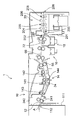
- the automatic developing device 1 shown in FIG. 2 has a development processing unit 10, and a development unit 14, a water washing unit 16, which is continuously formed along the transport direction (arrow A) of the transport path 12 of the planographic printing plate precursor, A desensitizing treatment unit 18 and a drying unit 20 are provided.
- the developing unit 14 is partitioned by an outer panel 111, and the outer panel 111 is provided with a slit-like insertion port 112.
- a developing tank 24 filled with a developing solution and an insertion roller pair 241 for guiding the planographic printing plate precursor into the developing tank 24 are provided inside the developing unit 14.
- the upper part of the developing tank 24 is covered with a shielding lid 242.
- a guide roller 143 and a guide member, a brush roller 141, a submerged transport roller 144, a brush roller 142, and a developing unit outlet roller are arranged in parallel from the upstream side in the transport direction.
- the lithographic printing plate precursor conveyed into the developing tank 24 is immersed in the developer and passes between the rotating brush rollers 141 and 142 to remove non-image portions.
- the lithographic printing plate carried out from the developing tank 24 is supplied with rinsing water by a rinsing spray 66 in the rinsing section 16, and the developer remaining on the plate surface and the like is removed by rinsing, and then the desensitizing processing section 18 performs gumming.
- the liquid (desensitizing liquid) supply spray 72 supplies the desensitizing liquid to the plate surface.
- the partition plate 201 disposed between the development processing unit 10 and the drying unit 20 is provided with a slit-shaped insertion port 202. Further, a shutter (not shown) is provided in the passage between the development processing unit 10 and the drying unit 20, and when the planographic printing plate precursor does not pass through the passage, the passage is closed by the shutter.
- the drying unit 20 includes a support roller 203, a duct 204, a transport roller pair 205, a duct 206, and a transport roller pair 208 in this order. Slit holes are provided at the ends of the ducts 204 and 205.
- the drying unit 20 is provided with drying means (drying member) such as hot air supply means (hot air supply member) and heat generation means (heat generation member) (not shown).
- drying means drying member
- hot air supply means hot air supply member
- heat generation means heat generation member
- the photosensitive lithographic printing plate precursor is subjected to a washing treatment step (ii) after being subjected to a development treatment step (i) [washing step (ii)].
- the water washing step is a step of washing the plate from which the protective layer and the image recording layer corresponding to the unexposed portion have been removed with a developer.
- the water may be water supplied directly from the water supply or water stored in a tank.
- the reclaimed water obtained by the recycling method of the development processing waste liquid of the present invention may be stored in a tank and used in the washing step.
- the washing water is usually sprayed from the washing spray 66 provided in the washing unit 16 onto the lithographic printing plate precursor that has undergone the development process.
- the lithographic printing plate precursor that has undergone the development treatment step and the water washing treatment step is subjected to plate making by applying a desensitizing solution at the desensitizing treatment unit 18 [desensitizing step (iii)], and the lithographic printing plate Is obtained.
- desensitizing treatment step (iii) Photosensitive lithographic printing plates from which the image recording layer in the unexposed area (non-image) has been removed by development processing and washing treatment are disclosed in JP-A Nos. 54-8002, 55-11545, and 59-58431. As described in the above, it is post-treated with a desensitizing solution containing a water-soluble polymer compound such as gum arabic and starch derivatives.
- the desensitizing treatment liquid is supplied to the plate surface by the desensitizing treatment liquid supply spray 72, and the surface of the non-image area is desensitized.
- the non-image area surface is desensitized to maintain the hydrophilicity of the non-image area surface in the lithographic printing plate appropriately, and the occurrence of stains in the non-image area is suppressed, so that the printing durability of the lithographic printing plate is maintained. Will be improved.
- the desensitizing treatment liquid to the surface of the image area, the scratch resistance of the image area is further improved.
- water-soluble polymer compound used in the preparation of the desensitizing solution in the present invention examples include soybean polysaccharide, modified starch, gum arabic, dextrin, fiber derivatives (eg, carboxymethylcellulose, carboxyethylcellulose, methylcellulose, etc.) and modified products thereof.
- Body pullulan, polyvinyl alcohol and its derivatives, polyvinylpyrrolidone, polyacrylamide and acrylamide copolymer, vinyl methyl ether / maleic anhydride copolymer, vinyl acetate / maleic anhydride copolymer, styrene / maleic anhydride copolymer Etc.
- the preferred acid value of the water-soluble polymer compound is 0 meq / g to 3.0 meq / g.
- the plate making waste liquid produced in the plate making step (i) is concentrated by an evaporation concentrator on a volume basis with a concentration (amount of plate making waste after concentration / amount of plate making waste before concentration) in volume. Evaporate and concentrate to 1/2 to 1/10 on the basis.
- the evaporative concentration apparatus includes at least an evaporating kettle that heats the waste liquid without depressurization or heats it under reduced pressure to separate the evaporated water and the remaining concentrate (slurry).
- the evaporative concentration apparatus further includes a cooling kettle that introduces moisture separated as water vapor that may contain an organic solvent into the evaporating kettle and condenses it by cooling to regenerate water.
- the concentration of the waste liquid is preferably performed by a method in which the inside of the evaporation pot is decompressed by a decompression means (a decompression member) and the waste liquid is concentrated by heating. This is because according to this method, the boiling point of the waste liquid is lowered, and the waste liquid can be evaporated and concentrated at a lower temperature than under atmospheric pressure. By using the depressurization means, the waste liquid can be concentrated more safely, and since the concentration is performed at a lower temperature, there is an advantage that the evaporating pot, the waste liquid, and the waste liquid concentrate are not easily affected by heat.
- a decompression means a decompression member
- Examples of pressure reducing means include general water seal type, oil rotary type, diaphragm type mechanical vacuum pumps, diffusion pumps using oil and mercury, multistage turbo compressors, reciprocating compressors, screw compressors, etc. Although a compressor and an aspirator are mentioned, an aspirator is preferable in terms of maintainability and cost.
- Examples of the depressurization condition include depressurization such that the pressure is 666.6 Pa (5 mmHg) to 13332.2 Pa (100 mmHg), preferably 666.6 Pa (5 mmHg) to 3999.7 Pa (30 mmHg).
- As the heating condition a temperature range corresponding to 666.6 Pa to 13332.2 Pa, which is a pressure easily obtained with a water pump or a vacuum pump, is selected.
- the heating temperature can be lowered and the power consumption can be suppressed.
- the heat pump preferably includes a heat radiating portion and a heat absorbing portion.
- the platemaking waste liquid is heated by the heat radiating portion of the heat pump, while the water vapor of the cooling means can be cooled by the heat absorbing portion of the heat pump. That is, the heat concentration of the waste liquid is performed by the heat generated by the heat pump, and the water vapor is condensed by the heat absorption of the heat pump, so that the heat efficiency is good and the heat becomes locally higher than when using heating means such as an electric heater. It has advantages such as being safer, safer, and reducing carbon dioxide emissions.
- the platemaking process waste liquid is heated by a heating means in an evaporation kettle so that the degree of concentration (the amount of the platemaking process waste liquid after concentration / plate making process before concentration) Evaporation is concentrated so that the amount of waste liquid is 1/2 to 1/10 of the volume.
- concentration is 1/2 or more, the amount of waste liquid to be processed is more effectively reduced, and when the concentration is 1/10 or less, the inside of the evaporation pot of the waste liquid concentrating device 30 is reduced.
- Precipitation of solids in the waste liquid concentrated in (1) is less likely to occur, resulting in better maintainability.
- the concentration is preferably in the range of 1/3 to 1/8.
- the reclaimed water obtained as described above is reclaimed water having a low BOD and COD value.
- the BOD value of the reclaimed water is approximately 250 mg / L or less and the COD value of the reclaimed water is 200 mg / L or less. Therefore, the excess reclaimed water may be discharged as it is into the general waste water.
- the reclaimed water contains an organic solvent or the like, a treatment with activated sludge or the like is performed before discharge. Further, as in the recycling method of the present invention to be described later, it is also preferable to recycle the recycled water by supplying it to the developing bath as dilution water or by supplying it as rinsing water in the rinsing section 16.
- a processing solution having a content of an organic solvent in the range of ⁇ 300 ° C. of 2% by mass or less and a pH of 6.0 to 9.5 As described above, the desensitization treatment step (iii) of the non-image area with the desensitizing liquid is performed.
- the development processing waste liquid generated in the development processing step is subjected to a ratio of the development processing waste liquid volume after concentration to the development processing waste liquid volume before concentration (concentration, That is, it occurs in the evaporation concentration step and the evaporation concentration step so that (amount of development processing waste liquid after concentration) / (amount of development processing waste liquid before concentration)) is 1/2 to 1/10 on a volume basis.
- the recycling method of the present invention further includes a reclaimed water supply step in addition to the plate making process, the waste liquid evaporation and concentration step, and the reclaimed water generation step.
- the generated reclaimed water may be supplied to a replenishing water tank or the like and used as diluting water for diluting the developing replenisher at a predetermined magnification in a developing bath disposed in an automatic processor.
- the developer replenisher may be mixed in advance and used to dilute the developer replenisher to a predetermined magnification.
- the reclaimed water may be supplied to the washing unit 14 of the automatic developing apparatus 1 and used as washing water.
- the reclaimed water may be supplied to the desensitizing treatment liquid tank in the desensitizing treatment unit 16.
- the waste liquid processing apparatus described in the gazette etc. is mentioned.
- an exemplary embodiment according to the present invention will be described with reference to the drawings.
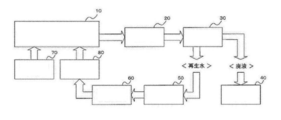
- the recycling method of the development processing waste liquid as shown in FIG. 1, the waste liquid of the developer discharged from the automatic processor 10 during the plate making process of the photosensitive lithographic printing plate is stored in the intermediate tank 20.
- the waste liquid stored and sent from the intermediate tank 20 is heated or heated under reduced pressure by the waste liquid concentrating device 30 and separated into evaporated water and residual concentrate (slurry).
- Reclaimed water obtained by condensing the water separated as water vapor by the waste liquid concentrator 30 by cooling is introduced into the reclaimed water tank 50.
- the waste liquid concentrated by the waste liquid concentrating device 30 is collected in the waste liquid collection tank 40. Transfer of the concentrated waste liquid to the waste liquid tank 40 is preferably performed by pressurizing with a pump.
- the waste liquid concentrator 30 is an evaporation pot (not shown) for separating the waste liquid sent from the intermediate tank 20 into heated water or under reduced pressure without reducing pressure, and separating it into evaporated water and residual concentrate (slurry). And a cooling kettle (not shown) that introduces moisture separated as water vapor (which may contain an organic solvent) in the evaporating kettle and condenses by cooling to form reclaimed water.
- a recycled water tank 50 that temporarily stores the recycled water and a distilled recycled water recycling apparatus 60 that controls the supply of the recycled water to the automatic developing machine 10 are used.
- the distilled reclaimed water reuse device 60 is preferably connected by piping to a replenishment water tank 80 for supplying reclaimed water to the automatic processor 10.
- a pipe connecting the replenishing water tank 80 and the developing bath of the automatic processor 10 is provided with a pressure gauge for measuring the pressure in the pipe and a pump.
- the distilled reclaimed water recycling apparatus 60 has an analyzer for analyzing the components of the reclaimed water, and means (members) for preparing a composition by performing neutralization, supplying fresh water, etc.
- the driving of the pump is controlled according to the pressure value measured by the pressure gauge, and the reclaimed water collected by driving the pump is supplied from the replenishing water tank 80 to the automatic developing device 10. Further, the developing replenisher is supplied from the developer replenisher tank 70 to the automatic developing machine 10.
- the reclaimed water obtained by this system may contain an organic solvent as long as it is 0.5% or less based on the volume.
- the reclaimed water obtained by this system is reclaimed water having a low BOD and COD value.
- the BOD value of reclaimed water obtained by the system is approximately 250 mg / L or less
- the COD value of reclaimed water is approximately 200 mg / L or less. Therefore, the reclaimed water is evaporated in an automatic processor. It can be used as a dilution water for correction, a dilution water for a developing replenisher, a rinsing water for washing a plate, or a washing water for an automatic developing machine. In addition, excess reclaimed water may be discharged as it is into general waste water.
- the developer replenisher is diluted and supplied to the developing bath of the automatic processor 10.
- the amount of reclaimed water supplied from the replenishing water tank 80 is controlled in accordance with the amount of developing replenisher supplied from the developer replenisher tank 70, and the system shown in FIG.
- the developing replenisher may be diluted at a predetermined magnification in a developing bath that is not used.
- the present invention is not limited to this embodiment, and the developer replenisher and regenerated water are mixed in advance to dilute the developer replenisher to a predetermined magnification, and then the diluted developer replenisher is supplied into the developing bath. May be.
- the platemaking process waste liquid generated from a plurality of automatic processors may be collected in one waste liquid concentrator, and the obtained reclaimed water may be supplied as dilution water or rinse water to the plurality of automatic processors.
- the reclaimed water as the replenishing water in this way, the processing amount of the lithographic printing plate precursor that is appropriately subjected to the plate making process is increased without supplying dilution water or the like to the automatic processor.
- a photosensitive lithographic printing plate precursor according to the present invention comprises a radically polymerizable image recording layer containing (a) an infrared absorbing dye, (b) a polymerization initiator, and (c) a polymerizable compound on a support; And a protective layer in this order.
- a radically polymerizable image recording layer containing (a) an infrared absorbing dye, (b) a polymerization initiator, and (c) a polymerizable compound on a support; And a protective layer in this order.
- the infrared absorbing dye has a function of converting the absorbed infrared light into heat and a function of being excited by the infrared light and transferring electrons and / or energy to a radical polymerization initiator described later.
- the infrared absorbing dye used in the present invention is a dye having an absorption maximum at a wavelength of 760 to 1200 nm.
- dyes such as azo dyes, metal complex azo dyes, pyrazolone azo dyes, naphthoquinone dyes, anthraquinone dyes, phthalocyanine dyes, carbonium dyes, quinoneimine dyes, methine dyes, cyanine dyes, squarylium dyes, pyrylium salts, metal thiolate complexes Is mentioned.
- cyanine dyes particularly preferred among these dyes are cyanine dyes, squarylium dyes, pyrylium salts, nickel thiolate complexes, and indolenine cyanine dyes. Further, cyanine dyes and indolenine cyanine dyes are preferred, and particularly preferred examples include cyanine dyes represented by the following general formula (e).
- X 1 represents a hydrogen atom, a halogen atom, —N (R 9 ) (R 10 ), —X 2 -L 1 or a group shown below.
- R 9 and R 10 may be the same or different, and may have a substituent, an aryl group having 6 to 10 carbon atoms, an alkyl group having 1 to 8 carbon atoms, or a hydrogen atom.
- R 9 and R 10 may be bonded to each other to form a ring. Of these, a phenyl group is preferred (—NPh 2 ).
- X 2 represents an oxygen atom or a sulfur atom
- L 1 represents a hydrocarbon group having 1 to 12 carbon atoms, a heteroaryl group, or a hydrocarbon group having 1 to 12 carbon atoms including a hetero atom.
- a hetero atom shows N, S, O, a halogen atom, or Se here.
- Xa - has Za described later - is defined as for, Ra represents a hydrogen atom, an alkyl group, an aryl group, a substituted or unsubstituted amino group, and substitutions selected from the group consisting of halogen atoms Represents a group.
- R 1 and R 2 each independently represents a hydrocarbon group having 1 to 12 carbon atoms.
- R 1 and R 2 are preferably each independently a hydrocarbon group having 2 or more carbon atoms.
- R 1 and R 2 may be connected to each other to form a ring, and when a ring is formed, it is particularly preferable to form a 5-membered ring or a 6-membered ring.
- Ar 1 and Ar 2 may be the same or different and each represents an aryl group which may have a substituent.
- Preferred aryl groups include a benzene ring and a naphthalene ring.
- a C12 or less hydrocarbon group, a halogen atom, and a C12 or less alkoxy group are mentioned.
- Y 1 and Y 2 may be the same or different and each represents a sulfur atom or a dialkylmethylene group having 12 or less carbon atoms.
- R 3 and R 4 may be the same or different and each represents a hydrocarbon group having 20 or less carbon atoms which may have a substituent.
- Preferred substituents include alkoxy groups having 12 or less carbon atoms, carboxy groups, and sulfo groups.
- R 5 , R 6 , R 7 and R 8 may be the same or different and each represents a hydrogen atom or a hydrocarbon group having 12 or less carbon atoms. From the availability of raw materials, a hydrogen atom is preferred.
- Za ⁇ represents a counter anion. However, Za ⁇ is not necessary when the cyanine dye represented by the general formula (e) has an anionic substituent in its structure and neutralization of charge is not necessary.
- Preferred Za ⁇ is a halide ion, a perchlorate ion, a tetrafluoroborate ion, a hexafluorophosphate ion, and a sulfonate ion, particularly preferably a perchlorate ion, in view of the storage stability of the image recording layer coating solution.
- Hexafluorophosphate ions, and aryl sulfonate ions are examples of the storage stability of the image recording layer coating solution.
- More preferable infrared absorbing dyes in the present invention include cyanine dyes represented by the following general formula (e-2).
- Z 1 and Z 2 each independently represent an aromatic ring or a heteroaromatic ring which may have a substituent.
- Preferred aromatic rings include a benzene ring and a naphthalene ring.
- Preferred substituents include a hydrocarbon group having 12 or less carbon atoms, a halogen atom, an alkoxy group having 12 or less carbon atoms, a hydrocarbon group having 12 or less carbon atoms, and 12 carbon atoms. Most preferred are not more than alkoxy groups.
- R 3 and R 4 each independently represent a hydrocarbon group having 20 or less carbon atoms which may have a substituent.
- Preferred substituents include alkoxy groups having 12 or less carbon atoms, carboxy groups, and sulfo groups.
- R 9 and R 10 each independently represent a hydrogen atom or an alkoxy group which may have a substituent.
- Za ⁇ represents a counter anion present when charge neutralization is required.
- Preferred Za ⁇ is a halide ion, a perchlorate ion, a tetrafluoroborate ion, a hexafluorophosphate ion, and a sulfonate ion, particularly preferably a perchlorate ion, in view of the storage stability of the image recording layer coating solution. , Hexafluorophosphate ions, and aryl sulfonate ions.
- cyanine dye represented by formula (e) that can be suitably used include compounds described in paragraphs [0017] to [0019] of JP-A No. 2001-133969, JP-A No. 2002-023360.
- Examples include the compounds described in paragraph numbers [0016] to [0021] of JP-A No. 2002-040638, paragraph numbers [0012] to [0037] of JP-A No. 2002-040638, and preferably paragraph Nos. Of JP-A No. 2002-278057.
- infrared absorbing dyes may be used alone or in combination of two or more, or an infrared absorbing pigment other than the infrared absorbing dye may be used in combination.
- pigment compounds described in paragraph numbers [0072] to [0076] of JP-A-2008-195018 are preferable.
- the content of the infrared absorbing dye in the image recording layer is preferably 0.1 to 10.0% by mass, more preferably 0.5 to 5.0% by mass, based on the total solid content of the image recording layer.
- the (b) radical generator is a compound that initiates and / or accelerates the polymerization of the (c) polymerizable compound.
- a known thermal polymerization initiator a compound having a bond with a small bond dissociation energy, a photopolymerization initiator, or the like can be used.
- radical generators are (1) organic halides, (2) carbonyl compounds, (3) azo compounds, (4) organic peroxides, (5) metallocene compounds, (6) azide compounds, (7) Examples include hexaarylbiimidazole compounds, (8) organic borate compounds, (9) disulfone compounds, (10) oxime ester compounds, and (11) onium salt compounds.
- the metallocene compound for example, the compound described in paragraph [0026] of JP-A-2008-195018 is preferable.
- the azide compound include compounds such as 2,6-bis (4-azidobenzylidene) -4-methylcyclohexanone.
- hexaarylbiimidazole compound for example, a compound described in paragraph [0027] of JP-A-2008-195018 is preferable.
- organic borate compound for example, compounds described in paragraph No. [0028] of JP-A-2008-195018 are preferable.
- Examples of the disulfone compound include compounds described in JP-A Nos. 61-166544 and 2002-328465.
- onium salt compounds examples include S.I. I. Schlesinger, Photogr. Sci. Eng. , 18, 387 (1974), T.A. S. Diazonium salts described in Bal et al, Polymer, 21, 423 (1980), ammonium salts described in US Pat. No. 4,069,055, JP-A-4-365049, etc., US Pat. No. 4,069 , 055, 4,069,056, phosphonium salts described in European Patent Nos. 104 and 143, U.S. Patent Application Publication No. 2008/0311520, JP-A-2-150848, Iodonium salts described in JP-A-2008-195018, European Patent Nos.
- German Patent 2,904 626 No. the 3,604,580 Patent, sulfonium salts described in the specification of Nos. 3,604,581, J. V. Crivello et al, Macromolecules, 10 (6), 1307 (1977), J. MoI. V. Crivello et al, J.A. Polymer Sci. , Polymer Chem. Ed. , 17, 1047 (1979), a selenonium salt described in C.I. S. Wen et al, Teh, Proc. Conf. Rad. Curing ASIA, p478 Tokyo, Oct (1988), and onium salts such as azinium salts described in JP-A-2008-195018.
- onium salts especially iodonium salts, sulfonium salts and azinium salts, and (7) hexaarylbiimidazole compounds. Specific examples of these compounds are shown below, but the scope of the present invention is not limited thereto.
- Examples of preferred iodonium salts include diphenyl iodonium salts, more preferred are diphenyl iodonium salts substituted with an electron donating group such as an alkyl group or an alkoxyl group, and even more preferred are asymmetric diphenyl iodonium salts. It is done.
- diphenyliodonium hexafluorophosphate
- 4-methoxyphenyl-4- (2-methylpropyl) phenyliodonium hexafluorophosphate
- 4- (2-methylpropyl) phenyl-p-tolyliodonium hexa Fluorophosphate
- 4-hexyloxyphenyl-2,4,6-trimethoxyphenyliodonium hexafluorophosphate
- 4-hexyloxyphenyl-2,4-diethoxyphenyliodonium tetrafluoroborate
- 4-octyloxy Phenyl-2,4,6-trimethoxyphenyliodonium 1-perfluorobutanesulfonate
- 4-octyloxyphenyl-2,4,6-trimethoxyphenyliodonium hexafluorophosphate, bis ( -t- butylphenyl) iodonium
- the hexaarylbiimidazole compounds include 2,2′-bis (o-chlorophenyl) -4,4 ′, 5,5′-tetraphenylbiimidazole, 2,2′-bis (o-bromophenyl)) 4, 4 ′, 5,5′-tetraphenylbiimidazole, 2,2′-bis (o, p-dichlorophenyl) -4,4 ′, 5,5′-tetraphenylbiimidazole, 2,2′-bis (o -Chlorophenyl) -4,4 ′, 5,5′-tetrakis (m-methoxyphenyl) biidazole, 2,2′-bis (o, o′-dichlorophenyl) -4,4 ′, 5,5′-tetraphenyl Biimidazole, 2,2′-bis (o-nitrophenyl) -4,4 ′, 5,5′-tetraphen
- the content of the radical generator is preferably 0.1% by mass to 50% by mass, more preferably 0.5% by mass to 30% by mass, and particularly preferably 0.8% by mass with respect to the total solid content of the image recording layer. ⁇ 20% by weight. Within this range, good sensitivity and good stain resistance of the non-image area during printing can be obtained.
- the polymerizable compound used in the image recording layer is an addition polymerizable compound having at least one ethylenically unsaturated double bond, and is selected from compounds having at least one terminal ethylenically unsaturated bond, preferably two or more. . These can take chemical forms such as monomers, prepolymers, ie dimers, trimers and oligomers, or mixtures thereof.
- Examples of monomers include unsaturated carboxylic acids (for example, acrylic acid, methacrylic acid, itaconic acid, crotonic acid, isocrotonic acid, maleic acid, etc.), esters and amides thereof, preferably unsaturated carboxylic acids.
- An ester of an acid and a polyhydric alcohol compound and an amide of an unsaturated carboxylic acid and a polyvalent amine compound are used.
- an addition reaction product of an unsaturated carboxylic acid ester or amide having a nucleophilic substituent such as a hydroxy group, an amino group or a mercapto group with a monofunctional or polyfunctional isocyanate or epoxy, and a monofunctional or polyfunctional compound.
- a dehydration condensation reaction product with a functional carboxylic acid is also preferably used.
- a substitution reaction product of an unsaturated carboxylic acid ester or amide having a leaving substituent such as a tosyloxy group and a monofunctional or polyfunctional alcohol, amine or thiol is also suitable.
- tris (acryloyloxyethyl) isocyanurate and bis (acryloyloxyethyl) hydroxyethyl are preferred because of the excellent balance between the hydrophilicity involved in on-press developability and the polymerization ability involved in printing durability.
- Isocyanuric acid ethylene oxide modified acrylates such as isocyanurates are particularly preferred.
- the details of the method of use such as the structure of these polymerizable compounds, whether only one is used or two or more are used together, and the amount added can be arbitrarily set in accordance with the performance design of the final lithographic printing plate precursor.
- the polymerizable compound is preferably 5% by mass to 75% by mass, more preferably 10% by mass to 70% by mass, and particularly preferably 15% by mass to 60% by mass with respect to the total solid content of the image recording layer. Used in range.
- a binder polymer may be used in order to improve the film strength of the image recording layer.
- the binder polymer any conventionally known polymer can be used without limitation, and a polymer having a film property is preferable. Of these, acrylic resins, polyvinyl acetal resins, and polyurethane resins are preferable.
- the main chain or the side chain preferably the side chain, has a crosslinkable functional group for improving the film strength of the image area. Things. Crosslinking is formed between the polymer molecules by the crosslinkable group, and curing is accelerated.
- the crosslinkable functional group is preferably an ethylenically unsaturated group such as a (meth) acryl group, vinyl group, allyl group, or styryl group, or an epoxy group, and these groups are introduced into the polymer by polymer reaction or copolymerization.
- a reaction between an acrylic polymer or polyurethane having a carboxy group in the side chain and polyurethane and glycidyl methacrylate, or a reaction between a polymer having an epoxy group and an ethylenically unsaturated group-containing carboxylic acid such as methacrylic acid can be used.
- the content of the crosslinkable group in the binder polymer is preferably 0.1 mmol to 10.0 mmol, more preferably 0.25 mmol to 7.0 mmol, and most preferably 0.5 mmol to 5.5 mmol per 1 g of the binder polymer. .
- the binder polymer preferably further has a hydrophilic group.
- the hydrophilic group contributes to imparting on-press developability to the image recording layer.
- the coexistence of the crosslinkable group and the hydrophilic group makes it possible to achieve both printing durability and developability.
- hydrophilic group examples include a hydroxy group, a carboxy group, an alkylene oxide structure, an amino group, an ammonium group, an amide group, a sulfo group, and a phosphoric acid group.
- an alkylene oxide unit having 2 or 3 carbon atoms An alkylene oxide structure having 1 to 9 is preferred.
- a monomer having a hydrophilic group may be copolymerized.
- an oleophilic group such as an alkyl group, an aryl group, an aralkyl group or an alkenyl group can be introduced in order to control the inking property.
- a lipophilic group-containing monomer such as an alkyl methacrylate may be copolymerized.
- the binder polymer Specific examples (1) to (11) of the binder polymer are shown below, but the present invention is not limited thereto.
- the number given to each repeating unit represents the molar ratio of the content of the repeating unit contained in the binder polymer.
- the binder polymer preferably has a mass average molar mass (Mw) of 2000 or more, more preferably 5000 or more, and still more preferably 10,000 to 300,000.
- the polymer compound used in the present invention is a star polymer having a main chain branched into three or more, and is a polymer compound represented by the following general formula (P-1).
- A represents a branch unit (constituent unit including a branch point) of a star polymer
- Polymer represents a polymer chain as a main chain, a polyethyleneoxy group and a polypropyleneoxy group as side chains. And a partial structure having at least one selected from a group. n is 3 or more.
- the star polymer is a polymer compound having a polymer chain having the main chain structure as described above and having at least one selected from a polyethyleneoxy group and a polypropyleneoxy group as a side chain.
- the side chain may contain only one of polyethyleneoxy group or polypropyleneoxy group, or may contain both groups.
- the polyethyleneoxy group or polypropyleneoxy group is a group represented by the following general formula (P-2).
- R 1 represents a hydrogen atom or a methyl group
- R 2 represents a hydrogen atom or an alkyl group having 1 to 12 carbon atoms
- n is preferably 2 to 90, more preferably 2 to 50, still more preferably. It represents 2 to 12, particularly preferably 2 to 8.
- R 1 is a hydrogen atom and R 2 is a hydrogen atom or a methyl group.
- n is more preferably from 2 to 12, and particularly preferably from 2 to 8.
- a monomer of the following general formula (P-3) may be copolymerized.
- R 3 represents a methyl group or a hydrogen atom
- L represents an oxygen atom or NH.
- L is preferably an oxygen atom.
- R 1, R 2 and n are general formula (P-2) have the same meanings as R 1, R 2 and n of a same preferred.
- the ratio of the repeating unit from the monomer represented by the general formula (3) is preferably 20% by mass to 80% by mass, more preferably 30% by mass to 70% in the polymer compound represented by the general formula (1). % By mass, particularly preferably 35% by mass to 65% by mass.
- the polymer of the general formula (P-1) includes a repeating unit having an ethylenically unsaturated group. Ethylenically unsaturated groups form crosslinks between polymer molecules during photopolymerization and promote photocuring.
- a (meth) acryl group As the ethylenically unsaturated group, a (meth) acryl group, a vinyl group, an allyl group and the like are preferable, and these groups can be introduced into a polymer by a polymer reaction or copolymerization.
- reaction between an acrylic polymer having a carboxy group in the side chain and glycidyl methacrylate reaction between a polymer having an epoxy group and an ethylenically unsaturated group-containing carboxylic acid such as methacrylic acid, or a polymer having a hydroxy group and an isocyanate group Reaction with methacrylate can be used.
- a (meth) acryl group is preferred.
- repeating unit having an ethylenically unsaturated group used in the present invention are described below.
- the present invention is not limited to these.
- the content of the ethylenically unsaturated group in the polymer compound of the present invention is preferably 0.1 mmol to 10.0 mmol, more preferably 0.25 mmol to 7.0 mmol, most preferably 0, per 1 g of the polymer compound. 0.5 mmol to 5.5 mmol.
- the star polymer may contain other repeating units. Specific examples of such repeating units are described below. The present invention is not limited to these.
- (M1) Acrylic acid esters and methacrylic acid esters having an aliphatic hydroxy group such as 2-hydroxyethyl acrylate or 2-hydroxyethyl methacrylate.
- (M2) Alkyl acrylates such as methyl acrylate, ethyl acrylate, propyl acrylate, butyl acrylate, amyl acrylate, hexyl acrylate, octyl acrylate, benzyl acrylate, 2-chloroethyl acrylate, and glycidyl acrylate.
- Alkyl methacrylates such as methyl methacrylate, ethyl methacrylate, propyl methacrylate, butyl methacrylate, amyl methacrylate, hexyl methacrylate, cyclohexyl methacrylate, benzyl methacrylate, 2-chloroethyl methacrylate and glycidyl methacrylate.
- (M4) Acrylamide, methacrylamide, N-methylolacrylamide, N-ethylacrylamide, N-hexylmethacrylamide, N-cyclohexylacrylamide, N-hydroxyethylacrylamide, N-phenylacrylamide, N-nitrophenylacrylamide, N-ethyl- Acrylamide or methacrylamide such as N-phenylacrylamide.
- (M5) Vinyl ethers such as ethyl vinyl ether, 2-chloroethyl vinyl ether, hydroxyethyl vinyl ether, propyl vinyl ether, butyl vinyl ether, octyl vinyl ether, and phenyl vinyl ether.
- (M6) Vinyl esters such as vinyl acetate, vinyl chloroacetate, vinyl butyrate and vinyl benzoate.
- Styrenes such as styrene, ⁇ -methylstyrene, methylstyrene, chloromethylstyrene.
- (M8) Vinyl ketones such as methyl vinyl ketone, ethyl vinyl ketone, propyl vinyl ketone, and phenyl vinyl ketone.
- Olefins such as ethylene, propylene, isobutylene, butadiene and isoprene.
- M10 N-vinylpyrrolidone, acrylonitrile, methacrylonitrile and the like.
- Unsaturated imides such as maleimide, N-acetylmethacrylamide, N-propionylmethacrylamide, N- (p-chlorobenzoyl) methacrylamide.
- the branch unit represented by A in the general formula (P-1) is not particularly limited, but preferably has a hub portion which is a residue of a thiol having 3 or more functionalities.
- the addition polymer backbone extends from each thio moiety in the hub; thus, three or more backbones extend from the thio moiety. That is, the branch unit A preferably has a structure represented by the following general formula (P-4).
- a 1 is a trivalent or higher organic group, and n is an integer of 3 or higher.
- Specific examples of A 1 include the following structures or organic groups constituted by combining a plurality of these structures.
- n is preferably an integer of 3 to 6, particularly preferably an integer of 4 to 6.
- Trifunctional or higher thiol residues are derived from aromatic or aliphatic thiols.
- aromatic thiols include benzene-1,3,5-trithiol, 3,4,8,9-tetramercaptotetrathiafulvalene and 7-methyltrithiouric acid.
- the thiol residue of the aliphatic thiol is preferably an ester residue formed from a trifunctional or higher alcohol and a mercaptoalkanoic acid having 2 to 6 carbon atoms.
- suitable alcohols include glycerin, sorbitol, alcohol represented by formula (P-5), and alcohol having a group represented by formula (P-6).
- an alcohol represented by the formula (P-5) and an alcohol having a group represented by the formula (P-6) are preferable.
- R 1 represents a hydrogen atom, an alkyl group having 1 to 4 carbon atoms, or a hydroxy-substituted alkyl group.
- a methyl group, an ethyl group, a hydroxymethyl group, and a hydroxyethyl group are preferable.
- Examples of mercaptoalkanoic acids having 2 to 6 carbon atoms include 2-mercaptoacetic acid, 2-mercaptopropionic acid, 3-mercaptopropionic acid, 4-mercaptobutyric acid, 5-mercaptovaleric acid, and 6-mercaptocaproic acid. It is done. Of these, 2-mercaptoacetic acid and 3-mercaptopropionic acid are preferable.
- esters formed from tri- or higher functional alcohols and mercaptoalkanoic acids having 2 to 6 carbon atoms include 1,2,6-hexanetriol trithioglycolate, 1,3,5-trithiocyanuric acid, 1,3,5-tris (3-mercaptobutyryloxyethyl) -1,3,5-triazine-2,4,6 (1H, 3H, 5H) -trione, trimethylolpropane tris (3-mercaptopropio Nate), trimethylolpropane tristhioglycolate, trimethylolpropane tristhiopropionate, trihydroxyethyltriisocyanuric acid tristhiopropionate, tris-[(ethyl-3-mercaptopropionyloxy) -ethyl] isocyanurate Compounds having three mercapto groups such as pentaerythritol Compounds having four mercapto groups such as tetrakis (3-
- TMTG trimethylolpropane tristhiopropionate
- PETG pentaerythritol tetrakisthiopropionate
- Karenz MT PE1 penta Erythritol tetrakis (3-mercaptobutyrate)
- Karenz MT PE1 trademark
- Karenz MT NR1 trimethylolpropane tris-3-mercaptopropionate
- PEMP pentaerythritol tetrakis-3- Mercaptopropionate
- Examples of the branch unit represented by formula (P-1) include those having the following structure.
- the weight average molecular weight (Mw) of the star polymer is preferably 5,000 to 500,000, and more preferably 10,000 to 250,000. Specific examples of the star polymer are shown in Table 1 below together with the weight average molecular weight depending on the branch unit and the type of polymer chain bonded to the tip. However, the star polymer that can be used in the present invention is not limited thereto.
- One type of star polymer may be included in the image recording layer, or two or more types may be included in the image recording layer.
- the content of the star polymer in the image recording layer is preferably in the range of 0.5% by mass to 90% by mass with respect to the total solid content of the image recording layer, and in the range of 1% by mass to 80% by mass. More preferably, it is more preferably in the range of 1.5 mass% to 70 mass%.
- the star polymer can be synthesized by a known method such as radical polymerization of the monomer constituting the polymer chain in the presence of the polyfunctional thiol compound.
- the image recording layer may contain fine polymer particles in order to improve developability.
- polymer fine particles having a polyalkylene oxide structure are preferred. Of these, polymer fine particles having a polyalkylene oxide group in the side chain are preferred.
- the polyalkylene oxide structure is preferably an alkylene oxide structure having 2 to 120 alkylene oxide units having 2 or 3 carbon atoms, and more preferably a polyethylene oxide structure having 2 to 120 ethylene oxide units. In particular, a polyethylene oxide structure having 20 to 100 ethylene oxide units is preferred.
- the fine polymer particles having such a polyalkylene oxide structure can achieve both printing durability and developability. Moreover, the inking property can be improved.
- the polymer fine particles are preferably a hydrophobized precursor that can convert the image recording layer to be hydrophobic when heat is applied.
- the hydrophobized precursor polymer fine particles include a group consisting of hydrophobic thermoplastic polymer fine particles, heat-reactive polymer fine particles, microcapsules enclosing at least a part of components of the image recording layer, and microgel (crosslinked polymer fine particles). At least one particle selected from the above is preferred. Among these, polymer fine particles and microgels having a polymerizable group are preferable. In order to improve developability, it is preferable to have a polyalkylene oxide structure as described above.
- Hydrophobic thermoplastic polymer fine particles include Research Disclosure No. 1 of January 1992. 331,003, JP-A-9-123387, JP-A-9-131850, JP-A-9-171249, JP-A-9-171250, and European Patent No. 931647 are suitable.
- polymer constituting the polymer fine particle examples include ethylene, styrene, vinyl chloride, methyl acrylate, ethyl acrylate, methyl methacrylate, ethyl methacrylate, vinylidene chloride, acrylonitrile, vinyl carbazole, acrylate having a polyalkylene structure, or Mention may be made of homopolymers or copolymers of monomers such as methacrylates or mixtures thereof. Among them, more preferable examples include a copolymer containing polystyrene, styrene and acrylonitrile, and polymethyl methacrylate.
- the average particle diameter of the hydrophobic thermoplastic polymer fine particles is preferably 0.01 ⁇ m to 2.0 ⁇ m.
- heat-reactive polymer fine particles examples include polymer fine particles having a heat-reactive group, and these form a hydrophobic region by cross-linking due to a heat reaction and a functional group change at that time.
- the heat-reactive group in the polymer fine particle having a heat-reactive group may be any functional group that performs a reaction as long as a chemical bond is formed, but an ethylenically unsaturated group that performs a radical polymerization reaction (for example, An acryloyl group, a methacryloyl group, a vinyl group, an allyl group, etc.), a cationic polymerizable group (for example, a vinyl group, a vinyloxy group, etc.), an isocyanate group that performs an addition reaction or a block thereof, an epoxy group, a vinyloxy group, and these reactions.
- a radical polymerization reaction for example, An acryloyl group, a methacryloyl group, a vinyl group, an allyl group, etc.
- a cationic polymerizable group for example, a vinyl group, a vinyloxy group, etc.
- an isocyanate group that performs an addition reaction or a block thereof, an epoxy group
- Functional group for example, amino group, hydroxy group, carboxy group, etc. having an active hydrogen atom as a partner, a carboxy group that performs a condensation reaction, a hydroxy group or amino group that is a reaction partner, an acid anhydride that performs a ring-opening addition reaction
- an amino group or a hydroxy group which is a reaction partner can be preferably mentioned.
- the microcapsule for example, as described in JP-A-2001-277740, JP-A-2001-277742, and EP2383118, all or part of the constituent components of the image recording layer are encapsulated in the microcapsule. Is mentioned.
- the constituent components of the image recording layer can also be contained outside the microcapsules.
- the image recording layer containing the microcapsule includes a hydrophobic constituent component in the microcapsule and a hydrophilic constituent component outside the microcapsule.
- the image recording layer may contain crosslinked resin particles, that is, microgel.
- the microgel can contain a part of the components of the image recording layer in and / or on the surface thereof.
- the aspect which made the reactive microgel by having a polymeric compound on the surface is especially preferable from a viewpoint of image formation sensitivity or printing durability.
- the average particle size of the microcapsules or microgel is preferably 0.01 ⁇ m to 3.0 ⁇ m. 0.05 ⁇ m to 2.0 ⁇ m is more preferable, and 0.10 ⁇ m to 1.0 ⁇ m is particularly preferable. Within this range, good resolution and stability over time can be obtained.
- the content of the polymer fine particles is preferably in the range of 5 mass% to 90 mass% of the total solid content of the image recording layer.
- the image recording layer can further contain the following components as required.
- the image recording layer may contain a low molecular weight hydrophilic compound in order to improve the on-press developability without reducing the printing durability.
- a low molecular weight hydrophilic compound for example, as the water-soluble organic compound, ethylene glycol, diethylene glycol, triethylene glycol, propylene glycol, dipropylene glycol, tripropylene glycol and the like glycols and ether or ester derivatives thereof, glycerin, Polyols such as pentaerythritol and tris (2-hydroxyethyl) isocyanurate, organic amines such as triethanolamine, diethanolamine and monoethanolamine and salts thereof, organic sulfones such as alkylsulfonic acid, toluenesulfonic acid and benzenesulfonic acid Acids and salts thereof, organic sulfamic acids such as alkylsulfamic acid and salts thereof, organic sulfuric acids such as alkyl
- the image recording layer preferably contains at least one selected from the group consisting of polyols, organic sulfates, organic sulfonates, and betaines.
- organic sulfonates include alkyl sulfonates such as sodium n-butyl sulfonate, sodium n-hexyl sulfonate, sodium 2-ethylhexyl sulfonate, sodium cyclohexyl sulfonate, and sodium n-octyl sulfonate.
- Organic sulfates include polyethylene oxide alkyl ether sulfates, polyethylene oxide alkenyl ether sulfates, polyethylene oxide alkynyl ether sulfates, polyethylene oxide aryl ether sulfates, or polyethylene oxide heterocyclic monoethers.
- the number of ethylene oxide units contained in the polyethylene oxide is preferably 1 to 4, and the sulfate is preferably a sodium salt, potassium salt or lithium salt. Specific examples thereof include compounds described in paragraph numbers [0034] to [0038] of JP-A-2007-276454.
- betaines compounds in which the hydrocarbon substituent on the nitrogen atom has 1 to 5 carbon atoms are preferable.
- Specific examples include trimethylammonium acetate, dimethylpropylammonium acetate, 3-hydroxy-4-trimethyl.
- the above low molecular weight hydrophilic compound has a small hydrophobic part structure and almost no surface-active action, so that dampening water penetrates into the exposed part of the image recording layer (image part) and the hydrophobicity and film strength of the image part. Ink acceptability and printing durability of the image recording layer can be maintained satisfactorily.
- the content of these low molecular weight hydrophilic compounds in the image recording layer is preferably 0.5% by mass or more and 20% by mass or less of the total solid content of the image recording layer. More preferably, they are 1 mass% or more and 15 mass% or less, More preferably, they are 2 mass% or more and 10 mass% or less. In this range, good on-press developability and printing durability can be obtained. Only one of these compounds may be included, or two or more combinations may be included.
- the image-recording layer may contain a fat-sensitizing agent such as a phosphonium compound, a nitrogen-containing low molecular weight compound, or an ammonium group-containing polymer in the image-recording layer in order to improve the inking property.
- a fat-sensitizing agent such as a phosphonium compound, a nitrogen-containing low molecular weight compound, or an ammonium group-containing polymer in the image-recording layer in order to improve the inking property.
- the sensitizer functions as a surface coating agent and prevents a decrease in the inking property during printing by the inorganic stratiform compound.
- the content of the sensitizer is preferably 0.01% by mass to 30.0% by mass, more preferably 0.1% by mass to 15.0% by mass with respect to the total solid content of the image recording layer, and 1% by mass. % To 10% by mass is more preferable.
- the image recording layer further comprises other components such as a surfactant, a colorant, a printout agent, a polymerization inhibitor, an ultraviolet absorber, a higher fatty acid derivative, a plasticizer, inorganic fine particles, an inorganic layered compound, and an increase.
- You may contain a sensitization agent or a chain transfer agent.
- the image recording layer is prepared by dispersing or dissolving the necessary components described above in a known solvent. It is formed by coating this on a support by a known method such as bar coater coating and drying.
- the image recording layer coating amount (solid content) on the support obtained after coating and drying varies depending on the use, but is generally preferably 0.3 g / m 2 to 3.0 g / m 2 . Within this range, good sensitivity and good film characteristics of the image recording layer can be obtained.
- the lithographic printing plate precursor preferably has an undercoat layer (sometimes referred to as an intermediate layer) between the image recording layer and the support.
- the undercoat layer enhances the adhesion between the support and the image recording layer in the exposed area, and easily peels off the image recording layer from the support in the unexposed area. Contributes to improvement.
- the undercoat layer functions as a heat insulating layer, thereby preventing the heat generated by the exposure from diffusing to the support and lowering the sensitivity.
- Examples of the compound used for the undercoat layer include compounds having an acid group such as phosphonic acid, phosphoric acid, and sulfonic acid. Further, those having an adsorptive group that can be adsorbed on the surface of the support and those having a crosslinkable group in order to improve adhesion to the image recording layer are preferred. These compounds may be low molecular weight or high molecular weight polymers. Two or more of these compounds may be used as necessary.
- the polymer is preferably a copolymer of a monomer having an adsorptive group, a monomer having a hydrophilic group, and a monomer having a crosslinkable group.
- the adsorptive group that can be adsorbed on the support surface include a phenolic hydroxy group, a carboxy group, —PO 3 H 2 , —OPO 3 H 2 , —CONHSO 2 —, —SO 2 NHSO 2 —, —COCH 2 COCH 3 Is preferred.
- a sulfo group is preferable.
- the crosslinkable group is preferably a methacryl group or an allyl group.
- This polymer may have a crosslinkable group introduced by salt formation between the polar substituent of the polymer, a substituent having a counter charge and a compound having an ethylenically unsaturated bond,
- Other monomers preferably hydrophilic monomers, may be further copolymerized.
- the phosphorus compound which has a heavy bond reactive group is mentioned suitably.
- Crosslinkable group (preferably ethylenically unsaturated bond group), support described in JP-A-2005-238816, JP-A-2005-125649, JP-A-2006-239867, JP-A-2006-215263 Those containing a low molecular compound or a high molecular compound having a functional group interacting with the surface and / or a hydrophilic group are also preferable. More preferred are polymer polymers having adsorbable groups, hydrophilic groups, and crosslinkable groups that can be adsorbed on the support surface described in JP-A Nos. 2005-125749 and 2006-188038.
- the content of unsaturated double bonds in the polymer for the undercoat layer is preferably 0.1 mmol to 10.0 mmol, more preferably 0.2 mmol to 5.5 mmol per 1 g of the polymer.
- the polymer for the undercoat layer preferably has a mass average molar mass of 5000 or more, more preferably 10,000 to 300,000.
- the undercoat layer according to the present invention includes a chelating agent, a secondary or tertiary amine, a polymerization inhibitor, an amino group, or a functional group having a polymerization inhibitory ability, in addition to the above-mentioned undercoat layer compound, to prevent contamination over time.
- a compound having a group that interacts with the surface of an aluminum support for example, 1,4-diazabicyclo [2,2,2] octane (DABCO), 2,3,5,6-tetrahydroxy-p-quinone, Chloranil, sulfophthalic acid, hydroxyethylethylenediaminetriacetic acid, dihydroxyethylethylenediaminediacetic acid, hydroxyethyliminodiacetic acid, etc.
- the undercoat layer is applied by a known method.
- the coating amount (solid content) of the undercoat layer is preferably 0.1 mg / m 2 to 100 mg / m 2 , and more preferably 1 mg / m 2 to 30 mg / m 2 .
- a support used for the photosensitive lithographic printing plate precursor a known support is used. Of these, an aluminum plate that has been roughened and anodized by a known method is preferred. If necessary, the aluminum plate may be subjected to a micropore expansion treatment or sealing treatment of an anodized film as described in JP-A No. 2001-253181 or JP-A No. 2001-322365, and / or US Pat. Alkali metal silicates or US patents as described in US Pat. Nos. 2,714,066, 3,181,461, 3,280,734 and 3,902,734 No. 3,276,868, No. 4,153,461 and No. 4,689,272, which have been subjected to surface hydrophilization treatment with polyvinylphosphonic acid or the like as described in each specification. Also good.
- the support preferably has a center line average roughness of 0.10 ⁇ m to 1.2 ⁇ m.
- the support used in the lithographic printing plate precursor may have an organic polymer compound described in JP-A No. 5-45885 or a silicon substrate described in JP-A No. 6-35174 on the back side. You may have the backcoat layer containing an alkoxy compound.
- the lithographic printing plate precursor preferably has a protective layer (overcoat layer) on the image recording layer.
- the protective layer has a function of preventing scratches in the image recording layer and preventing ablation during high-illuminance laser exposure.
- the protective layer having such characteristics are described in, for example, US Pat. No. 3,458,311 and JP-B-55-49729.
- the low oxygen permeability polymer used for the protective layer either a water-soluble polymer or a water-insoluble polymer can be appropriately selected and used, and two or more types can be mixed and used as necessary. it can.
- Specific examples include polyvinyl alcohol, modified polyvinyl alcohol, polyvinyl pyrrolidone, water-soluble cellulose derivatives, poly (meth) acrylonitrile, and the like.
- the modified polyvinyl alcohol acid-modified polyvinyl alcohol having a carboxy group or a sulfo group is preferably used.
- modified polyvinyl alcohols described in JP-A-2005-250216 and JP-A-2006-259137 are suitable.
- the protective layer is a hydrophilic polymer having a repeating unit represented by the following general formula (1) and a repeating unit represented by the general formula (2) described in JP 2012-73597 A (hereinafter referred to as a specific hydrophilic group). It is particularly preferable that the polymer contains a polymer.
- R 1 and R 4 each independently represent a hydrogen atom or a methyl group.
- R 2 and R 3 each independently represents a hydrogen atom, a methyl group, or an ethyl group.
- R 5 represents a linear, branched or cyclic unsubstituted alkyl group having 2 to 8 carbon atoms, a substituted alkyl group which may have an aromatic ring or a heterocyclic ring as a substituent, or a group represented by the following general formula (3): Represents a substituent. Examples of the substituent that can be introduced into the substituted alkyl group include an aromatic ring group, a heterocyclic group, and a polyether group.
- L represents an alkylene group having 2 to 6 carbon atoms
- R 6 represents a linear, branched or cyclic unsubstituted alkyl group or aromatic substituted alkyl group having 4 to 8 carbon atoms.
- n is the average number of moles of polyether added and represents a number of 2 to 4. It is preferable that R 2 and R 3 of the repeating unit represented by the general formula (1) are both hydrogen atoms.
- R 5 of the repeating unit represented by the general formula (2) is preferably a linear, branched or cyclic unsubstituted alkyl group having 2 to 8 carbon atoms.
- R 1 and R 4 in the formula (1) and formula (2) are each a hydrogen atom
- R 5 in general formula (2) is a branched and unsubstituted alkyl group having 4 carbon atoms is most preferable.
- the specific hydrophilic polymer preferably further has a repeating unit represented by the following general formula (4).
- R 7 represents a hydrogen atom or a methyl group.
- X represents a single bond, a divalent linking group selected from the structures shown in the following structural group (5), or a divalent linking group formed by combining a plurality selected from the structures shown in the following structural group (6).
- Y is a carboxylic acid group, a carboxylic acid group, a sulfonic acid group, a sulfonic acid group, a phosphoric acid group, a phosphoric acid group, a phosphonic acid group, a phosphonic acid group, a hydroxyl group, a carboxybetaine group, a sulfobetaine group, an ammonium group, or Represents a polyether group represented by the following general formula (7).
- Y is preferably a sulfonic acid group, a sulfonic acid group, a carboxybetaine group, a sulfobetaine group, or an ammonium group from the viewpoint of water solubility and on-press developability. More preferably a sulfonic acid group, a sulfonic acid group or a sulfobetaine group.
- X is a divalent linking chain selected from the structures shown in the following structural group (5), or a divalent linking group formed by combining a plurality selected from the structures shown in the following structural group (6). Is preferred.
- L ′ represents an alkylene group having 2 to 3 carbon atoms
- R 8 represents a hydrogen atom or a methyl group
- n ′ is an average added mole number of the polyether and is a number of 2 to 4.
- the monomer derived from the repeating unit represented by the general formula (1) include acrylamide, methacrylamide, N-methylacrylamide, N-methylmethacrylamide, N-ethylacrylamide, N-ethylmethacrylamide, N, Examples thereof include N-dimethylacrylamide, N, N-dimethylmethacrylamide, N, N-diethylacrylamide, N, N-diethylmethacrylamide, N, N-ethylmethylacrylamide and N, N-ethylmethylmethacrylamide.
- the monomer derived from the repeating unit represented by the general formula (2) include methyl acrylate, ethyl acrylate, propyl acrylate, isopropyl acrylate, n-butyl acrylate, i-butyl acrylate, acrylic T-butyl acid, pentyl acrylate, hexyl acrylate, cyclohexyl acrylate, heptyl acrylate, octyl acrylate, 2-ethylhexyl acrylate, nonyl acrylate, decyl acrylate, 2- (2-ethylhexyloxyethoxy) acrylate Ethyl, methyl methacrylate, ethyl methacrylate, propyl methacrylate, isopropyl methacrylate, n-butyl methacrylate, i-butyl methacrylate, t-butyl methacrylate, pentyl methacrylate,
- the content of the repeating unit represented by the general formula (1) in the specific hydrophilic polymer is preferably 65 mol% to 96.7 mol%, more preferably 70 mol% to 80 mol%, and 74 mol% to 80 mol%. % Is particularly preferred.
- the content of the repeating unit represented by the general formula (2) in the specific hydrophilic polymer is preferably 3 mol% to 30 mol%, more preferably 20 mol% to 30 mol%, and more preferably 20 mol% to 26 mol%. Particularly preferred.
- the monomer derived from the repeating unit represented by the general formula (4) include 2-acryloylamino-2-methyl-propanesulfonic acid, sodium 2-acryloylamino-2-methyl-propanesulfonate, -Potassium acryloylamino-2-methyl-propanesulfonate, 4-((3-methacrylamidopropyl) dimethylammonio) butane-1-sulfonate, 4-((3-acrylamidopropyl) dimethylammonio) butane-1- Sulfonate, vinyl alcohol, acrylic acid, methacrylic acid, sodium styrene sulfonate, diethylene glycol monomethyl ether methacrylate, hydroxyethyl acrylate, hydroxyethyl methacrylate, methacrylcholine chloride, 3-sulfomethacrylate Ropirukariumu, 2- phosphate (methacryloyloxy) ethyl, dimethyl -N
- the specific hydrophilic polymer preferably contains 0.3 mol% to 5 mol% of the repeating unit represented by the general formula (4), more preferably contains 0.3 mol% to 3 mol%. Those containing 3 mol% to 1.5 mol% are more preferable.
- the specific hydrophilic polymer used in the protective layer contains the repeating unit represented by the general formula (4) in the above-mentioned preferable range, the photosensitive lithographic printing plate precursor has good on-press developability, inking property and printing durability. You can get sex.
- the weight average molecular weight (Mw) of the specific hydrophilic polymer is preferably in the range of 10,000 to 200,000, more preferably in the range of 10,000 to 100,000, and 10,000 to 30,0000. Most preferably, it is in the range of 000.
- the content of the specific hydrophilic polymer in the protective layer is preferably 40% by mass or more of the solid content of the protective layer. More preferably, it is 60 mass% or more, Most preferably, it is 80 mass% or more. Within this range, a lithographic printing plate having better inking properties and higher printing durability can be obtained, and a lithographic printing plate precursor excellent in on-press development can be obtained.
- the protective layer preferably contains an inorganic layered compound such as natural mica and synthetic mica as described in JP-A-2005-119273 in order to enhance oxygen barrier properties.
- the protective layer may contain a known additive such as a plasticizer for imparting flexibility, a surfactant for improving coatability, inorganic fine particles for controlling surface slipperiness, and / or an ultraviolet absorber. it can. Further, the protective layer can contain the sensitizer described in the description of the image recording layer.
- the adhesiveness and scratch resistance with the image recording layer are considered from the viewpoint of handling the plate. That is, when a hydrophilic protective layer mainly composed of a water-soluble polymer is laminated on an oleophilic image recording layer, film peeling due to insufficient adhesive force is likely to occur, and the peeled portion may be poorly cured due to oxygen polymerization inhibition. Cause defects.
- various proposals have been made to improve the adhesion between these two layers. For example, in Japanese Patent Publication No. 54-12215 and British Patent Application No. 1303578, an acrylic emulsion or a water-insoluble vinylpyrrolidone-vinyl acetate copolymer is mixed in a protective layer in an amount of 20% to 60% by weight. By doing so, it is described that sufficient adhesiveness can be obtained. Any of these known techniques can be applied to the protective layer of the photosensitive lithographic printing plate precursor used in the method of the present invention.
- the coating amount of the protective layer is, the coating amount after drying is preferably in the range of 0.01g / m 2 ⁇ 10g / m 2, more preferably in the range of 0.02g / m 2 ⁇ 3g / m 2, Most preferably, it is in the range of 0.02 g / m 2 to 1 g / m 2 .
- a photosensitive lithographic printing plate precursor applied to the development processing step according to the waste liquid concentration method of the present invention and the recycling method of the present invention is obtained.
- the photosensitive lithographic printing plate precursor is imagewise exposed and developed to produce a lithographic printing plate.
- the lithographic printing plate precursor is developed with a developer in a development treatment bath of an automatic processor, and then subjected to a water washing treatment and a desensitizing treatment. As described above, it is provided sequentially.
- the lithographic printing plate precursor is imagewise exposed by laser exposure through a transparent original image having a line image, a halftone dot image or the like, or by laser beam scanning by digital data.
- the wavelength of the light source used for exposure is preferably 300 nm to 450 nm or 750 nm to 1400 nm.
- a lithographic printing plate precursor having a sensitizing dye having a maximum absorption wavelength in this region in the image recording layer is used.
- the wavelength of the light source is 750 nm to 1400 nm, this region is used.
- a lithographic printing plate precursor containing an infrared absorbing agent which is a sensitizing dye having absorption in an image recording layer is used.
- a semiconductor laser is suitable as a light source for light having a wavelength of 300 nm to 450 nm.
- a light source for light having a wavelength of 750 nm to 1400 nm a solid-state laser and a semiconductor laser that emit infrared light are suitable.
- the exposure mechanism may be any of an internal drum system, an external drum system, a flat bed system, and the like.
- the developer described above can be used as a developer and a development replenisher for the exposed lithographic printing plate precursor, and is preferably applied to a developer bath of an automatic processor as described above.
- the developing solution becomes fatigued according to the amount of processing, and therefore the replenishing solution or fresh developing solution may be supplemented to restore the developing processing capability.
- This replenishment method is also preferably applied to the recycling method of the present invention.
- the entire surface may be heated before exposure, during exposure, or between exposure and development, if necessary.
- Such heating promotes an image forming reaction in the image recording layer, and may have advantages such as improvement in sensitivity and printing durability and stabilization of sensitivity.
- it is also effective to subject the developed image to full post heating or full exposure.
- heating before development is preferably performed under a mild condition of 150 ° C. or less. If the preheating temperature is too high, problems such as fogging in the non-image area occur. Very strong conditions are used for the heat treatment after development.
- the temperature of the post-heating treatment is in the range of 200 ° C to 500 ° C. If the temperature of the post-heating treatment is too low, sufficient image strengthening action cannot be obtained, and if it is too high, the support is deteriorated and the image portion is thermally decomposed.
- the molecular weight is a weight average molecular weight (Mw), and the ratio of the repeating units is a mole percentage, unless otherwise specified.
- This plate was etched by being immersed in a 25 mass% sodium hydroxide aqueous solution at 45 ° C for 9 seconds, washed with water, further immersed in 20 mass% nitric acid at 60 ° C for 20 seconds, and washed with water. At this time, the etching amount of the grained surface was about 3 g / m 2 .
- an electrochemical roughening treatment was performed continuously using an alternating voltage of 60 Hz.
- the electrolytic solution at this time was a 1% by mass nitric acid aqueous solution (containing 0.5% by mass of aluminum ions) and a liquid temperature of 50 ° C.
- AC power supply waveform is 0.8 msec until the current value reaches the peak from zero, duty ratio is 1: 1, and trapezoidal rectangular wave alternating current is used to perform electrochemical surface roughening treatment with the carbon electrode as the counter electrode. went. Ferrite was used for the auxiliary anode.
- the current density was 30 A / dm 2 at the peak current value, and 5% of the current flowing from the power source was shunted to the auxiliary anode.
- the amount of electricity in nitric acid electrolysis was 175 C / dm 2 when the aluminum plate was the anode. Then, water washing by spraying was performed.
- nitric acid electrolysis was performed with an aqueous solution of 0.5% by mass of hydrochloric acid (containing 0.5% by mass of aluminum ions) and an electrolytic solution having a liquid temperature of 50 ° C. under the condition of an electric quantity of 50 C / dm 2 when the aluminum plate was the anode.
- an electrochemical surface roughening treatment was performed, followed by washing with water by spraying.
- a direct current anodic oxide film of 2.5 g / m 2 was provided on this plate by treating the plate with 15% by mass sulfuric acid (containing 0.5% by mass of aluminum ions) at an electric current density of 15 A / dm 2 .
- the support (1) was subjected to a silicate treatment at 60 ° C. for 10 seconds using an aqueous 2.5 mass% No. 3 sodium silicate solution, and then washed with water for support.
- Body (2) was obtained.
- the amount of Si attached to the surface of the support (2) was 10 mg / m 2 .
- the center line average roughness (Ra) of the support (2) was measured using a needle having a diameter of 2 ⁇ m and found to be 0.51 ⁇ m.
- undercoat layer coating solution (1) having the following composition is applied on the support (2) so that the dry coating amount is 20 mg / m 2 and used in the following experiments.
- a support having an undercoat layer was prepared.
- the image recording layer coating solution (C) was obtained by mixing and stirring a photosensitive solution (1) and a microgel solution (1) having the following composition immediately before coating.
- Binder polymer (1), infrared absorber (2), radical generator (1), phosphonium compound (1), low molecular weight hydrophilic compound (1), ammonium group-containing polymer, and fluorine-based surfactant (1) The structure is as shown below.
- microgel (1) As an oil phase component, trimethylolpropane and xylene diisocyanate adduct (trade name: Takenate D-110N, manufactured by Mitsui Takeda Chemical Co., Ltd., 75 mass% ethyl acetate solution), 10 g, Aronix SR-399 (trade name, Tojo) Synthetic Co., Ltd. (6.00 g) and Pionein A-41C (trade name, Takemoto Yushi Co., Ltd.) 0.12 g were dissolved in ethyl acetate 16.67 g.
- aqueous phase component 37.5 g of a 4 mass% aqueous solution of PVA-205 (trade name, manufactured by Kuraray Co., Ltd.) was prepared.
- the oil phase component and the aqueous phase component were mixed and emulsified for 10 minutes at 12000 rpm using a homogenizer.
- the obtained emulsion was added to 25 g of distilled water, stirred at room temperature for 30 minutes, and then stirred at 40 ° C. for 2 hours.
- the microcapsule solution thus obtained was diluted with distilled water so that the solid content concentration was 15% by mass, and this was designated as microgel (1).
- the average particle size of the microgel (1) measured by a dry particle size distribution analyzer (trade name: LA-910, manufactured by Horiba, Ltd.) was 0.2 ⁇ m.
- inorganic layered compound dispersion (1) 6.4 g of synthetic mica (trade name: Somasif ME-100, manufactured by Corp Chemical Co., Ltd.) is added to 193.6 g of ion-exchanged water, and dispersed using an homogenizer until the average particle size (laser scattering method) becomes 3 ⁇ m. did.
- the aspect ratio of the obtained dispersed particles was 100 or more.
- ⁇ Composition of coating liquid (1) for protective layer> ⁇ Inorganic layered compound dispersion (1) (obtained above) 1.5 g Hydrophilic polymer (1) (solid content) [the following structure, Mw: 30,000] 0.55 g ⁇ Polyvinyl alcohol (trade name: CKS50, manufactured by Nippon Synthetic Chemical Industry Co., Ltd., sulfonic acid modification, saponification degree 99 mol% or more, polymerization degree 300) 6% by mass aqueous solution 0.10 g Polyvinyl alcohol (trade name: PVA-405, manufactured by Kuraray Co., Ltd., saponification degree 81.5 mol%, polymerization degree 500) 6% by mass aqueous solution 0.03 g -Surfactant (trade name: Emalex 710, manufactured by Nippon Emulsion Co., Ltd.) 1% by weight aqueous solution 0.86 g ⁇ Ion-exchanged water 6.0g
- a photosensitive lithographic printing plate precursor for evaluation having an image recording layer and a protective layer was produced on the support.
- the obtained photosensitive lithographic printing plate precursor was subjected to plate making according to the following steps, and the development waste liquid generated in the development processing step was concentrated.
- New Coal B13 (trade name, manufactured by Nippon Emulsifier Co., Ltd.), which is a surfactant used in the preparation of the developers (A) to (C) and (I) to (K), is represented by the general formula (B). It is a nonionic surfactant having an included naphthalene skeleton.
- Nonionic surfactant polyoxyethylene naphthalene ether
- New Coal B13 manufactured by Nippon Emulsifier Co., Ltd., solid content 100%
- Chelating agent ethylenediamine disuccinic acid trisodium salt
- Kirest EDDS-35 manufactured by Kirest Co., Ltd.
- Silicone-based antifoaming agent trade name: TSA739, manufactured by Momentive Performance Materials Japan GK
- TSA739 manufactured by Momentive Performance Materials Japan GK
- Nonionic surfactant polyoxyethylene naphthalene ether
- New Coal B13 manufactured by Nippon Emulsifier Co., Ltd., solid content 100%
- Chelating agent ethylenediamine disuccinic acid trisodium salt
- Kirest EDDS-35 manufactured by Kirest Co., Ltd.
- Silicone-based antifoaming agent trade name: TSA739, manufactured by Momentive Performance Materials Japan GK
- Actide LA1206, manufactured by So Japan Co., Ltd. 0.1% by mass Water was added to make the total amount 100% by mass.
- Phosphoric acid added to adjust pH to 8.0
- Anionic surfactant sodium alkylnaphthalene sulfonate
- Perex NBL manufactured by Kao Corporation, 35% aqueous solution
- Chelating agent ethylenediamine disuccinic acid trisodium salt
- Kirest EDDS-35
- Perex NBL (trade name, manufactured by Kao Co., Ltd.), which is a surfactant used for preparing the developer (D), is an anionic surfactant having a naphthalene skeleton included in the general formula (A). .
- Anionic surfactant polyoxyethylene aryl ether sulfate ester salt
- Chelating agent ethylenediamine disuccinic acid trisodium salt
- Kirest EDDS-35 manufactured by Kirest
- Neucor B4-SN (trade name, manufactured by Nippon Emulsifier Co., Ltd.), which is a surfactant used for preparing the developer (E), is an anionic interface having a naphthalene skeleton included in the general formula (A). It is an activator.
- Anionic surfactant sodium dodecyl diphenyl ether disulfonate
- Chelating agent ethylenediamine disuccinic acid trisodium salt
- Kirest EDDS-35 manufactured by Kirest Co.
- Eleminol MON-2 (trade name, manufactured by Sanyo Kasei Kogyo Co., Ltd.), a surfactant used for the preparation of the developer (F), is an anion outside the scope of the present invention, which does not have a naphthalene skeleton in the molecule. Surfactant.
- Nonionic surfactant polyoxyethylene distyrenated phenyl ether
- Emulgen A-90 manufactured by Kao Corporation, solid content 100%
- Chelating agent ethylenediamine disuccinic acid trisodium salt
- Kirest EDDS-35 manufactured by Kirest Co., Ltd.
- Silicone-based antifoaming agent trade name: TSA739, manufactured by Momentive Performance Materials Japan GK
- Preservative Brand name: Bio Hope, manufactured by KAI Kasei Co., Ltd.
- Emulgen A-90 (trade name, manufactured by Kao Co., Ltd.), which is a surfactant used in the preparation of the developer (G), has no naphthalene skeleton in the molecule and is a nonionic interface outside the scope of the present invention. It is an activator.
- Anionic surfactant diodecylbenzene sulfonate
- New Coal 210 manufactured by Nippon Emulsifier Co., Ltd., 50% aqueous solution
- Chelating agent ethylenediamine
- Neucor 210 (trade name, manufactured by Nippon Emulsifier Co., Ltd.), a surfactant used for the preparation of the developer (H), has no naphthalene skeleton in the molecule and is an anionic interface outside the scope of the present invention. It is an activator.
- Nonionic surfactant polyoxyethylene naphthalene ether
- New Coal B13 manufactured by Nippon Emulsifier Co., Ltd., solid content 100%
- Benzyl alcohol 1.0 mass%
- Chelating agent ethylenediamine disuccinic acid trisodium salt
- Kirest EDDS-35 manufactured by Kirest Co., Ltd.
- Silicone-based antifoaming agent trade name: TSA739, manufactured by Momentive Performance Materials Japan GK
- TSA739 manufactured by Momentive Performance Materials Japan GK
- Actide LA1206, manufactured by So Japan 0.1% by mass Water was added to make the total amount 100% by mass.
- Phosphoric acid added to adjust pH to 8.0
- Nonionic surfactant polyoxyethylene naphthalene ether
- New Coal B13 manufactured by Nippon Emulsifier Co., Ltd., solid content 100%
- Chelating agent ethylenediamine disuccinic acid trisodium salt
- Kirest EDDS-35 manufactured by Kirest Co., Ltd.
- Silicone-based antifoaming agent trade name: TSA739, manufactured by Momentive Performance Materials Japan GK
- Actide LA1206, manufactured by So Japan Co., Ltd. 0.1% by mass Water was added to make the total amount 100% by mass.
- Phosphoric acid added to adjust pH to 8.0
- Nonionic surfactant polyoxyethylene naphthalene ether
- New Coal B13 manufactured by Nippon Emulsifier Co., Ltd., solid content 100%
- Chelating agent ethylenediamine disuccinic acid trisodium salt
- Kirest EDDS-35 manufactured by Kirest Co., Ltd.
- Silicone-based antifoaming agent trade name: TSA739, manufactured by Momentive Performance Materials Japan GK
- Actide LA1206, manufactured by So Japan Co., Ltd. 0.1% by mass Water was added to make the total amount 100% by mass.
- the comparative developer (K) is a developer outside the scope of the present invention having a specific organic solvent content of 2.0% by mass or
- Nonionic surfactant polyoxyethylene naphthalene ether
- New Coal B13 manufactured by Nippon Emulsifier Co., Ltd., solid content 100%
- Chelating agent ethylenediamine disuccinic acid trisodium salt
- Kirest EDDS-35 manufactured by Kirest Co., Ltd.
- Silicone-based antifoaming agent trade name: TSA739, manufactured by Momentive Performance Materials Japan GK
- Actide LA1206, manufactured by So Japan Co., Ltd. 0.1% by mass Water was added to make the total amount 100% by mass.
- the comparative developer (L) is a developer having a pH of 5.0 that is outside the scope of the present invention.
- Nonionic surfactant polyoxyethylene naphthalene ether
- New Coal B13 manufactured by Nippon Emulsifier Co., Ltd., solid content 100%
- Chelating agent ethylenediamine disuccinic acid trisodium salt
- Kirest EDDS-35 manufactured by Kirest Co., Ltd.
- Silicone-based antifoaming agent trade name: TSA739, manufactured by Momentive Performance Materials Japan GK
- Actide LA1206, manufactured by So Japan Co., Ltd. 0.1% by mass Water was added to make the total amount 100% by mass.
- the comparative developer (M) is a developer having a pH of 10.0 and outside the scope of the present invention.
- ⁇ Plate making of photosensitive lithographic printing plate precursor> The resulting photosensitive lithographic printing plate precursor (1) was subjected to the following steps to produce a lithographic printing plate. (Exposure process) The obtained photosensitive lithographic printing plate precursor was exposed under the conditions of either exposure A or exposure B below. ⁇ Exposure A> The resulting lithographic printing plate precursor was subjected to a Luxel PLASETTER T-6000III (trade name, manufactured by Fuji Film Co., Ltd.) equipped with an infrared semiconductor laser, and the external drum rotation speed was 1000 rpm, the laser output was 70%, and the resolution was 2400 dpi (dot per inch). The exposure was performed under the following conditions. The exposure image includes a solid image and a 50% halftone dot chart of a 20 ⁇ m dot FM screen.
- ⁇ Exposure B> The resulting lithographic printing plate precursor was exposed to a Trendsette R3244VX (trade name, manufactured by Creo) equipped with an infrared semiconductor laser at an output of 6.4 W under conditions of an outer drum rotation speed of 150 rpm and a resolution of 2400 dpi.
- the exposure image includes a solid image and a 50% halftone dot chart of a 20 ⁇ m dot FM screen.
- the resulting lithographic printing plate was stored for 10 days in a storage environment of 30 ° C.-75% RH, and then developed without imagewise exposure.
- the developing solution of Table 3 was used for the developing solution.
- the density of the non-image area of the lithographic printing plate obtained by development was measured using a Macbeth reflection densitometer RD-918 and a cyan density using a red filter equipped in the densitometer.
- the difference between the density value of the support having been subjected to the hydrophilization surface treatment before the application of the protective layer, the photosensitive layer and the undercoat layer and the density value of the non-image area after the development treatment was evaluated according to the following criteria.
- A is a level with no practical problem and C is an unusable level for practical use.
- planographic printing plate precursor and obtained planographic printing plate
- the on-press developability of the planographic printing plate precursor (1) was confirmed as follows. Further, the lithographic printing plate obtained through the plate making process was evaluated for the inking property (initial inking property, inking property with special ink) and printing durability in the following manner. The inking property with the special color ink was also evaluated when the lithographic printing plate precursor was aged.
- the obtained lithographic printing plate precursor was subjected to an external drum rotation speed of 1000 rpm, a laser output of 70%, and a resolution of 2400 dpi on a Fujifilm Corporation-made Luxel PLASETTER T-6000III equipped with an infrared semiconductor laser. Exposed.
- the exposure image includes a solid image and a 50% halftone dot chart of a 20 ⁇ m dot FM screen.
- the obtained exposed original plate was attached to a plate cylinder of a printing machine LITHRONE 26 manufactured by Komori Corporation without developing.
- the lithographic printing plate obtained by the above development treatment is printed using a printing machine (trade name: Diamond 1F-2, manufactured by Mitsubishi Heavy Industries) and printed out. Therefore, the number of printed sheets until a good printed matter was obtained without fading the image area ink density was evaluated.
- Graph G (trade name, manufactured by DIC Corporation) was used as the printing ink.
- the fountain solution used was IF mark II (trade name, manufactured by Fuji Film). After the start of printing, the ink gradually adheres to the image recording layer, and as a result, the ink density on the paper increases.
- the number of printed sheets when the ink density reached the standard printed matter density (Macbeth reflection density D 1.80) was evaluated as the ink inking property according to the following criteria. The smaller the number of printed sheets, the better the fillability.
- Resistance After exposure (exposure B), the lithographic printing plate obtained by the above development treatment is attached to a cylinder of a printing press (trade name: Speedmaster R52, manufactured by Heidelberg), and dampening water [trade name: IF102, Fuji Film ( Co., Ltd., Etch solution) / water 3/97 (volume ratio) mixture] and black ink (trade name: TRANS-G (N), manufactured by DIC Corporation) 100 sheets were printed at a printing speed.
Abstract
Description
通常の製版処理廃液はアルカリ性が強いものであるが、平版印刷版原版として、特段のアルカリ現像処理を行うことなく露光後の非画像部を除去しうる所謂無処理タイプの平版印刷版原版が注目されている。無処理タイプの平版印刷版原版は、アルカリ現像浴での現像処理を必要とせず、露光後、印刷機にセットして印刷を行うことで、印刷処理の早い段階でインクや湿し水により未露光部が現像されるものである。このような無処理タイプの平版印刷版原版においても、印刷用紙の使用量を低減させ、処理効率を上げる目的で、中性から比較的低いアルカリ性の現像液で現像する現像処理が行われる。無処理タイプの平版印刷版原版の現像処理には界面活性剤を含有する現像処理液が使用されるが、この廃液もまた、そのままでは一般排水として排出することができず、なんらかの廃液処理が必要である。
しかし、廃液処理に至るまでには、廃液の貯蔵に多大なスペースが必要となる。また廃液処理設備は、かなり広大な場所を必要とする等の問題を有している。 Conventionally, when a photosensitive lithographic printing plate precursor is developed with an automatic processor, the concentration and pH of components lost during processing and aging are kept constant, and a developer replenisher is added to maintain the performance of the developer. A means for supplying the developer in the process is employed. Even if such replenishment is performed, if the performance of the developer falls outside the allowable limit, all of the developer is discarded.
Normal plate-making process waste liquid is strongly alkaline, but as a lithographic printing plate precursor, a so-called non-processing type lithographic printing plate precursor capable of removing a non-image area after exposure without performing special alkali development processing is attracting attention. Has been. An unprocessed type lithographic printing plate precursor does not require development processing in an alkaline developer bath. After exposure, it is set in a printing machine and printed, so that it is not used with ink or dampening water at an early stage of the printing process. The exposed part is developed. Even in such an unprocessed type lithographic printing plate precursor, development processing is performed in which development is performed with a neutral to relatively low alkaline developer in order to reduce the amount of printing paper used and increase processing efficiency. A developing solution containing a surfactant is used for the development of an unprocessed lithographic printing plate precursor, but this waste solution cannot be discharged as general wastewater as it is, and some sort of waste solution treatment is required. It is.
However, enormous space is required to store the waste liquid before the waste liquid treatment. Further, the waste liquid treatment facility has a problem that it requires a considerably large space.
また、製版処理廃液の排出量を削減することができ、製版処理廃液の処理過程で生じる水を容易に再利用できる平版印刷版製版処理廃液削減装置が提案されている(例えば、特許第4774124号公報)。 For such problems, a method of concentrating the waste liquid by blowing warm air into the waste liquid storage tank (for example, Japanese Patent Laid-Open No. 5-341535) or neutralizing the treatment waste liquid and adding a flocculant to aggregating components A method for agglomerating (for example, Japanese Patent Laid-Open No. 2-157084) has been proposed.
In addition, a planographic printing plate making waste liquid reduction device that can reduce the discharge amount of the plate making waste liquid and can easily reuse water generated in the process of the plate making waste liquid has been proposed (for example, Japanese Patent No. 4774124). Publication).
凝集剤を用いる技術では、廃液の処理にコストがかかり、さらに、製版処理廃液に高分子化合物を含有する場には、蒸発釜内に残った固形物が飴状となって蒸発釜の壁面に付着し、汚れやすく、また廃液処理装置の配管が詰まり易いなど、メンテナンスが煩雑であった。
通常のアルカリ現像処理を必要とするネガ型或いはポジ型の感光性画像記録層を有する平版印刷版原版の製版処理については、上述のように種々の検討がなされているが、無処理タイプの平版印刷版原版の製版処理における廃液の問題については、未だ十分な検討がなされていない。 In the waste liquid concentration technique using hot air, the amount of evaporation is not large, so the effect of reducing the amount of waste liquid is not sufficient, and a long time is required to sufficiently concentrate the plate making waste liquid. Furthermore, it does not support the treatment of evaporated water.
In the technology using the flocculant, the waste liquid processing is costly, and when the plate making waste liquid contains a polymer compound, the solid matter remaining in the evaporation pot becomes a bowl-like shape on the wall of the evaporation pot. Maintenance has been complicated, such as adhesion and contamination, and clogging of the piping of the waste liquid treatment apparatus.
Various studies have been made on the plate-making process of a lithographic printing plate precursor having a negative or positive photosensitive image recording layer that requires a normal alkali development process as described above. The problem of the waste liquid in the plate making process of the printing plate precursor has not yet been fully studied.
また、本発明は、現像処理廃液を濃縮する際に得られた再生水を、現像液、水洗水、不感脂化処理液等に再利用することにより、自動現像機の現像浴や不感化処理浴中での堆積物の蓄積による汚れが少なく、長時間連続的に製版処理した場合においても析出物の発生が抑制される、現像処理廃液のリサイクル方法を提供しうる。 The present invention was made in consideration of the above problems, and in the development processing step by an automatic processor, the development debris generation in the development bath is suppressed without reducing the development speed, and the stain resistance and the inking property are reduced. In the development waste liquid concentration process, foaming at the time of concentration of the waste liquid is suppressed, the foam is efficiently concentrated, solid precipitation is suppressed, and washing of the concentration kettle and the like is easy. It is possible to provide a development processing waste liquid concentration method that can be performed.
In addition, the present invention recycles the reclaimed water obtained when concentrating the development processing waste liquid into a developing solution, washing water, a desensitizing processing solution, etc., so that a developing bath or a desensitizing processing bath of an automatic processor is used. It is possible to provide a method for recycling a developing treatment waste liquid that is less contaminated by accumulation of deposits therein and that suppresses the generation of precipitates even when the plate making process is continued for a long time.
[1] 支持体上に(a)赤外線吸収染料、(b)重合開始剤、及び(c)重合性化合物、を含有するラジカル重合性の画像記録層と、保護層と、をこの順に有する感光性平版印刷版原版を露光後、現像する自動現像機の現像処理浴中で、該露光後の感光性平版印刷版原版を、ナフタレン骨格を有するアニオン性界面活性剤及びナフタレン骨格を有するノニオン性界面活性剤からなる群より選ばれる少なくとも一つを1質量%~10質量%含有し、沸点が100℃~300℃の範囲にある有機溶剤の含有量が2質量%以下であり、pHが6.0~9.5である現像液により現像処理することにより生じた現像処理廃液を得る工程、及び、前記現像処理廃液を、蒸発濃縮装置で、濃縮前の現像処理廃液の量に対する濃縮後の現像処理廃液の量の比が容量基準で1/2~1/10となるように、蒸発濃縮する工程、を含む感光性平版印刷版の現像処理廃液濃縮方法。 As a result of intensive studies, the present inventors have found that the above-described problems can be solved by using a developer containing a specific surfactant during development, and the present invention has been completed. That is, the configuration of the present invention is as follows.
[1] Photosensitive having a radically polymerizable image recording layer containing (a) an infrared absorbing dye, (b) a polymerization initiator, and (c) a polymerizable compound, and a protective layer in this order on a support. A photosensitive lithographic printing plate precursor after exposure in a developing bath of an automatic processor that develops the photosensitive lithographic printing plate precursor after exposure to an anionic surfactant having a naphthalene skeleton and a nonionic interface having a naphthalene skeleton At least one selected from the group consisting of activators is contained in an amount of 1% by mass to 10% by mass, the content of an organic solvent having a boiling point in the range of 100 ° C. to 300 ° C. is 2% by mass or less, and the pH is 6. A step of obtaining a development processing waste solution generated by developing with a developing solution of 0 to 9.5, and developing the development processing waste solution after concentration with respect to the amount of the development processing waste solution before concentration using an evaporation concentrator Ratio of amount of processing waste liquid A method for concentrating a development processing waste liquid of a photosensitive lithographic printing plate, comprising a step of evaporating and concentrating so that the ratio becomes 1/2 to 1/10 on a volume basis.
[3] 界面活性剤が、オキシエチレン基及びオキシプロピレン基からなる群より選択される少なくとも一つを含むポリオキシアルキレン鎖を含む化合物である、[1]又は[2]に記載の方法。
[4] ポリオキシアルキレン鎖に繰り返し単位として含まれるオキシエチレン基及びオキシプロピレン基の数が合計で5~30である、[3]に記載の方法。
[5] 保護層が、少なくとも下記一般式(1)で表される繰返し単位と下記一般式(2)で表される繰返し単位とを含む親水性ポリマーを含有する保護層である、[1]~[4]のいずれか1項に記載の方法。 [2] The method according to [1], including a step of condensing the water vapor generated in the evaporation concentration step by cooling to generate regenerated water.
[3] The method according to [1] or [2], wherein the surfactant is a compound containing a polyoxyalkylene chain containing at least one selected from the group consisting of an oxyethylene group and an oxypropylene group.
[4] The method according to [3], wherein the total number of oxyethylene groups and oxypropylene groups contained as repeating units in the polyoxyalkylene chain is 5 to 30.
[5] The protective layer is a protective layer containing a hydrophilic polymer containing at least a repeating unit represented by the following general formula (1) and a repeating unit represented by the following general formula (2): [1] The method according to any one of [4] to [4].
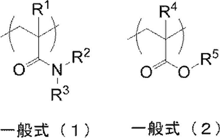

[6] 親水性ポリマーが、さらに、下記一般式(4)で表される繰返し単位を含む、[5]に記載の方法。 In the general formula (3), L represents an alkylene group having 2 to 6 carbon atoms, and R 6 represents a linear, branched or cyclic unsubstituted alkyl group or aromatic substituted alkyl group having 4 to 8 carbon atoms. . n represents the average number of moles added of the polyether and is in the range of 2-4.
[6] The method according to [5], wherein the hydrophilic polymer further contains a repeating unit represented by the following general formula (4).


[8] 感光性平版印刷版原版を、現像処理工程後、水洗工程、及び不感脂化液による非画像部の不感脂化処理工程を経て製版することを含む、[7]に記載の方法。 [7] Photosensitive having a radically polymerizable image recording layer containing (a) an infrared absorbing dye, (b) a polymerization initiator, and (c) a polymerizable compound, and a protective layer in this order on the support. After exposure of the lithographic printing plate precursor, the photosensitive lithographic printing plate precursor after the exposure is developed in a developing bath of an automatic processor that develops the anionic surfactant having a naphthalene skeleton and the nonionic surfactant having a naphthalene skeleton. At least one selected from the group consisting of an agent is contained in an amount of 1 to 10% by mass, the content of an organic solvent having a boiling point in the range of 100 ° C. to 300 ° C. is 2% by mass or less, and the pH is 7.0. The ratio of the amount of the development processing waste liquid after concentration to the amount of the development processing waste liquid before concentration in the step of developing with the developing solution of 9.5, the development processing waste liquid generated in the development processing step with the evaporation concentration device Is 1 / on a volume basis A step of evaporating and concentrating so as to be 2 to 1/10, a step of condensing the water vapor generated in the evaporative concentration step by cooling to generate reclaimed water, and a step of supplying the reclaimed water to the automatic processor. Recycling process waste liquid for photosensitive lithographic printing plate containing
[8] The method according to [7], comprising making the photosensitive lithographic printing plate precursor through a development step, a water washing step, and a desensitization treatment step for a non-image area with a desensitizing solution.
また、本発明によれば、現像処理廃液を濃縮する際に得られた再生水を、現像液、水洗水、不感脂化処理液等に再利用することにより、自動現像機の現像浴や不感化処理浴中での堆積物の蓄積による汚れが少なく、長時間連続的に製版処理した場合においても析出物の発生が抑制される、現像処理廃液のリサイクル方法が提供される。 According to the present invention, in the development processing step by an automatic processor, the development of scum in the development bath is suppressed without reducing the development speed, and a lithographic printing plate excellent in stain resistance and inking property is obtained. Development processing in which the foaming at the time of concentration of the waste liquid is suppressed in the development waste liquid concentration step, the waste liquid is efficiently concentrated, the precipitation of solids is suppressed, and the concentration kettle can be easily washed. A waste liquid concentration method is provided.
In addition, according to the present invention, the reclaimed water obtained when concentrating the development processing waste liquid is reused in the developing solution, washing water, desensitizing processing solution, etc. Provided is a method for recycling a development processing waste liquid that is less contaminated by accumulation of deposits in a processing bath and that suppresses the generation of precipitates even when a plate-making process is performed continuously for a long time.
本明細書における数値範囲の表示は、当該数値範囲の下限値として表示される数値を最小値として含み、当該数値範囲の上限値として表示される数値を最大値として含む範囲を示す。 本明細書における基(原子団)の表記に於いて、置換及び/又は無置換を特定していない表記は、置換基を有さないものと共に置換基を有するものをもその基(原子団)の範囲に包含するものである。例えば、「アルキル基」とは、置換基を有さないアルキル基(無置換アルキル基)のみならず、置換基を有するアルキル基(置換アルキル基)をも包含するものである。
本明細書中、アクリル酸、メタクリル酸のいずれか或いは双方を示すため「(メタ)アクリル酸」と表記することがあり、アクリレート、メタクリレートのいずれか或いは双方を示すため「(メタ)アクリレート」と表記することがある。
成分の含有量は特に断りのない限り質量換算で示し、特に断りのない限り、質量%は、組成物の総量に対する割合を表し、「固形分」とは、組成物中の溶媒を除く成分を表す。
本明細書において「工程」との語は、独立した工程だけでなく、他の工程と明確に区別できない場合であっても工程の所期の作用が達成されれば、本用語に含まれる。
本明細書中における重量平均分子量は、ゲル透過クロマトグラフ(GPC)で測定した値である。GPCは、HLC-8020GPC(東ソー(株)製)を用い、カラムとしてTSKgel SuperHZM-H、TSKgel SuperHZ4000、TSKgel SuperHZ200(東ソー(株)製、4.6mmID×15cm)を、溶離液としてTHF(テトラヒドロフラン)を用い、カラムオーブンの設定温度を40℃として測定した。分子量の算出には標準ポリスチレンを用いた。 In this specification, when referring to the amount of each component in the composition, when there are a plurality of substances corresponding to each component in the composition, the amount is present in the composition unless otherwise specified. Means the total amount of the plurality of substances.
The display of a numerical range in this specification indicates a range including a numerical value displayed as a lower limit value of the numerical range as a minimum value and a numerical value displayed as an upper limit value of the numerical range as a maximum value. In the notation of a group (atomic group) in the present specification, a notation that does not specify substitution and / or non-substitution includes those having no substituent and those having a substituent (group). It is included in the range. For example, the “alkyl group” includes not only an alkyl group having no substituent (unsubstituted alkyl group) but also an alkyl group having a substituent (substituted alkyl group).
In this specification, “(meth) acrylic acid” may be used to indicate either or both of acrylic acid and methacrylic acid, and “(meth) acrylate” may be used to indicate either or both of acrylate and methacrylate. Sometimes written.
Unless otherwise specified, the content of the component is expressed in terms of mass. Unless otherwise specified, the mass% represents a ratio with respect to the total amount of the composition, and “solid content” refers to the component excluding the solvent in the composition. To express.
In this specification, the term “process” is not limited to an independent process, and is included in the term if the intended action of the process is achieved even when it cannot be clearly distinguished from other processes.
The weight average molecular weight in this specification is a value measured by gel permeation chromatography (GPC). GPC uses HLC-8020GPC (manufactured by Tosoh Corporation), TSKgel SuperHZM-H, TSKgel SuperHZ4000, TSKgel SuperHZ200 (4.6 mmID × 15 cm, Tosoh Corporation) as columns and THF (tetrahydrofuran) as an eluent. And the column oven was set at a set temperature of 40 ° C. Standard polystyrene was used for calculation of molecular weight.
本発明の一実施形態である感光性平版印刷版の現像処理廃液濃縮方法(以下、廃液濃縮方法と称することがある)は、支持体上に(a)赤外線吸収染料、(b)重合開始剤、及び(c)重合性化合物を含有するラジカル重合性の画像記録層と、保護層と、をこの順に有する感光性平版印刷版原版を露光後、現像する自動現像機の現像処理浴中で、該露光後の感光性平版印刷版原版を、ナフタレン骨格を有するアニオン性界面活性剤及びナフタレン骨格を有するノニオン性界面活性剤からなる群より選ばれる少なくとも一つの界面活性剤を1質量%~10質量%含有し、沸点が100℃~300℃の範囲にある有機溶剤の含有量が2質量%以下であり、pHが6.0~9.5である現像液により現像処理する工程において生じた現像処理廃液を得る工程、及び、蒸発濃縮装置で、濃縮度(濃縮後の現像処理廃液の量/濃縮前の現像処理廃液の量)が容量基準で1/2~1/10となるように、蒸発濃縮する工程、を含む。
前記画像記録層には、例えば、(d)バインダーポリマーなど、他の公知の成分を含んでいてもよい。
ある実施態様においては、廃液濃縮方法はさらに、前記蒸発濃縮工程において生じた水蒸気を冷却により凝縮して再生水を生成させる工程を含んでもよい。 [Method for concentrating development processing waste liquid of photosensitive lithographic printing plate]
One embodiment of the present invention is a method for concentrating development waste liquid of a photosensitive lithographic printing plate (hereinafter sometimes referred to as waste liquid concentration method) on a support (a) an infrared absorbing dye and (b) a polymerization initiator. And (c) a radically polymerizable image recording layer containing a polymerizable compound, and a protective lithographic printing plate precursor having a protective layer in this order in a developing bath of an automatic processor for developing after exposure, The photosensitive lithographic printing plate precursor after the exposure contains 1% by mass to 10% by mass of at least one surfactant selected from the group consisting of an anionic surfactant having a naphthalene skeleton and a nonionic surfactant having a naphthalene skeleton. The development occurred in the step of developing with a developer having a content of organic solvent having a boiling point of 100 ° C. to 300 ° C. of 2% by mass or less and a pH of 6.0 to 9.5. Treatment waste liquid And evaporating and concentrating in an evaporative concentration apparatus so that the concentration (the amount of development processing waste liquid after concentration / the amount of development processing waste liquid before concentration) is 1/2 to 1/10 on a volume basis. Process.
The image recording layer may contain other known components such as (d) a binder polymer.
In a certain embodiment, the waste liquid concentration method may further include a step of condensing the water vapor generated in the evaporation concentration step by cooling to generate reclaimed water.
以下、本発明の廃液濃縮方法について、工程順に説明する。使用される感光性平版印刷版原版及び現像工程に先立つ露光工程については後述する。
〔製版処理工程〕
本発明に係る感光性平版印刷版原版の製版処理は、少なくとも、露光工程に引き続き行われる現像処理工程(i)、水洗工程(ii)、及び不感脂化処理工程(iii)をこの順に有する。本発明の廃液濃縮方法は、製版処理における現像処理工程(i)において発生する現像廃液を濃縮する方法に係わる。ある実施態様において、本発明の廃液濃縮方法における現像処理廃液を得る工程には、現像処理工程(i)が含まれてもよい。 In the photosensitive lithographic printing plate precursor according to the present invention, the image recording layer on the support is exposed, and (c) the polymerizable compound is cured by the function of the active species generated from the polymerization initiator (b) in the exposed region. A so-called latent image is formed, and then an unexposed area (non-cured area) is removed by development, the cured area becomes an ink-receptive image area, and the unexposed area that has been developed and removed becomes a non-image area. Produced.
Hereinafter, the waste liquid concentration method of the present invention will be described in the order of steps. The photosensitive lithographic printing plate precursor used and the exposure step prior to the development step will be described later.
[Plate making process]
The plate-making process of the photosensitive lithographic printing plate precursor according to the present invention includes at least a development process step (i), a water washing step (ii), and a desensitizing treatment step (iii) performed in this order following the exposure step. The waste liquid concentration method of the present invention relates to a method for concentrating the development waste liquid generated in the development processing step (i) in the plate making process. In one embodiment, the step of obtaining a development processing waste liquid in the waste liquid concentration method of the present invention may include a development processing step (i).
感光性平版印刷版原版は、後述する露光工程において像様に露光され、露光部が硬化された後、現像処理工程(i)に付される。
(現像液)
まず、本発明の廃液濃縮方法において好適に使用される現像液について説明する。
本発明の現像処理廃液において、感光性平版印刷版の現像に用いる使用される現像液について説明する。
なお、本明細書中において、特にことわりのない限り、現像液とは、現像開始液(狭義の現像液)と現像補充液とを包含する意味で用いられる。
本発明に適用される現像液(現像開始液及び現像補充液)は、ラジカル重合性の画像記録層を有する感光性平版印刷版原版を現像するための現像液であり、ナフタレン骨格を有するアニオン性界面活性剤及びナフタレン骨格を有するノニオン性界面活性剤からなる群より選ばれる少なくとも一つの界面活性剤を現像液全量に対して1質量%~10質量%含有し、沸点が100℃~300℃の範囲にある有機溶剤の含有量が2質量%以下であり、且つ、pHが6.0~9.5である現像液である。ここで、「沸点が100℃~300℃の範囲にある有機溶剤の含有量が2質量%以下である」とは、沸点が100℃~300℃の範囲にある有機溶剤を含有しない状態(沸点が100℃~300℃の範囲にある有機溶剤の含有量が不可避不純物を除いて0質量%である状態)を包含する意味で使用される。
ある実施形態において、現像液は、沸点が100℃より低い又は300℃より高い有機溶剤を実質的に含有しないことが好ましい。ここで「沸点が100℃より低い又は300℃より高い有機溶剤を実質的に含有しない」とは、沸点が100℃より低い又は300℃より高い有機溶剤の含有量が0.2質量%未満であることである。本発明に係る現像液は、沸点が100℃より低い又は300℃より高い有機溶剤を含有しないことが好ましい。 [Development processing step (i)]
The photosensitive lithographic printing plate precursor is subjected to imagewise exposure in an exposure step described later, and after the exposed portion is cured, it is subjected to a development processing step (i).
(Developer)
First, the developing solution used suitably in the waste liquid concentration method of this invention is demonstrated.
The developing solution used for developing the photosensitive lithographic printing plate in the development processing waste solution of the present invention will be described.
In the present specification, unless otherwise specified, the term “developer” is used to include a development starter (a developer in a narrow sense) and a development replenisher.
The developer (development initiator and developer replenisher) applied to the present invention is a developer for developing a photosensitive lithographic printing plate precursor having a radically polymerizable image recording layer, and has an anionic property having a naphthalene skeleton. At least one surfactant selected from the group consisting of a surfactant and a nonionic surfactant having a naphthalene skeleton is contained in an amount of 1% by mass to 10% by mass with respect to the total amount of the developer, and has a boiling point of 100 ° C. to 300 ° C. The developer has a content of the organic solvent in the range of 2% by mass or less and a pH of 6.0 to 9.5. Here, “the content of the organic solvent having a boiling point in the range of 100 ° C. to 300 ° C. is 2% by mass or less” means that the organic solvent having a boiling point in the range of 100 ° C. to 300 ° C. is not contained (boiling point In the range of 100 ° C. to 300 ° C., the content of the organic solvent is 0% by mass excluding inevitable impurities).
In certain embodiments, it is preferred that the developer be substantially free of organic solvents having boiling points below 100 ° C or above 300 ° C. Here, “substantially no organic solvent having a boiling point lower than 100 ° C. or higher than 300 ° C.” means that the content of the organic solvent having a boiling point lower than 100 ° C. or higher than 300 ° C. is less than 0.2% by mass. That is. The developer according to the present invention preferably does not contain an organic solvent having a boiling point lower than 100 ° C or higher than 300 ° C.
本発明における現像液に含まれる界面活性剤は、ナフタレン骨格を有するアニオン性界面活性剤及びナフタレン骨格を有するノニオン性界面活性剤からなる群より選択される少なくとも一つの界面活性剤(以下、適宜、特定界面活性剤と称する)である。ある実施態様において、特定界面活性剤は、オキシエチレン基及びオキシプロピレン基からなる群より選択される少なくとも一つを含む化合物であってよい。ある実施態様において、オキシエチレン基及び/又はオキシプロピレン基は、ポリオキシアルキレン鎖を構成する繰り返し単位として特定界面活性剤に含まれてよく、その繰り返し単位数は5~30であってよい。ある実施態様において、特定界面活性剤は、ポリオキシエチレン鎖及び/又はポリオキシプロピレン鎖からなる群より選択される少なくとも一つを含む化合物であってよい。
本発明に使用される現像液において最適なナフタレン骨格を有するアニオン性界面活性剤としては、例えば、ナフタレン骨格を有するスルホン酸塩及びナフタレン骨格を有する硫酸塩が好ましく挙げられ、より好ましくは、置換基を有していてもよいナフタレンスルホン酸塩、及び下記一般式(A)で表される化合物が挙げられる。
置換基を有していてもよいナフタレンスルホン酸塩において、置換基としては炭素原子数1~20のアルキル基が好ましく、これらのアルキル基が1~4個ナフタレン環に置換されていることが好ましく、これらのアルキル基が1~2個ナフタレン環に置換されていることがより好ましい。スルホン酸塩はナフタレン環に1~3個置換しているものが好ましく、ナフタレン環に1~2個置換しているものがより好ましい。スルホン酸塩は好ましくはナトリウム塩、カリウム塩、又はアンモニウム塩である。
具体的にはジ-ターシャリーブチルナフタレンスルホン酸ナトリウム、モノターシャリーブチルナフタレンスルホン酸ナトリウム、ジ-ターシャリーブチルナフタレンジスルホン酸ナトリウム、モノターシャリーブチルナフタレンジスルホン酸ナトリウムあるいはこれらの混合物を挙げることができる。
ナフタレン骨格を有するアニオン性界面活性剤としては、下記一般式(A)で表されるアニオン界面活性剤が好ましい。 (Surfactant selected from anionic surfactants having a naphthalene skeleton and nonionic surfactants having a naphthalene skeleton)
The surfactant contained in the developer in the present invention is at least one surfactant selected from the group consisting of an anionic surfactant having a naphthalene skeleton and a nonionic surfactant having a naphthalene skeleton (hereinafter, appropriately, Referred to as a specific surfactant). In one embodiment, the specific surfactant may be a compound containing at least one selected from the group consisting of an oxyethylene group and an oxypropylene group. In one embodiment, the oxyethylene group and / or oxypropylene group may be included in the specific surfactant as a repeating unit constituting the polyoxyalkylene chain, and the number of repeating units may be 5 to 30. In one embodiment, the specific surfactant may be a compound containing at least one selected from the group consisting of a polyoxyethylene chain and / or a polyoxypropylene chain.
Preferred examples of the anionic surfactant having a naphthalene skeleton in the developer used in the present invention preferably include a sulfonate having a naphthalene skeleton and a sulfate having a naphthalene skeleton, and more preferably a substituent. And a compound represented by the following general formula (A).
In the naphthalene sulfonate which may have a substituent, the substituent is preferably an alkyl group having 1 to 20 carbon atoms, and these alkyl groups are preferably substituted with 1 to 4 naphthalene rings. More preferably, these alkyl groups are substituted with 1 to 2 naphthalene rings. The sulfonate is preferably substituted with 1 to 3 naphthalene rings, and more preferably substituted with 1 to 2 naphthalene rings. The sulfonate is preferably a sodium salt, potassium salt or ammonium salt.
Specific examples include sodium ditertiary butyl naphthalene sulfonate, sodium monotertiary butyl naphthalene sulfonate, sodium di-tertiary butyl naphthalene disulfonate, sodium monotertiary butyl naphthalene disulfonate, or a mixture thereof. .
As the anionic surfactant having a naphthalene skeleton, an anionic surfactant represented by the following general formula (A) is preferable.

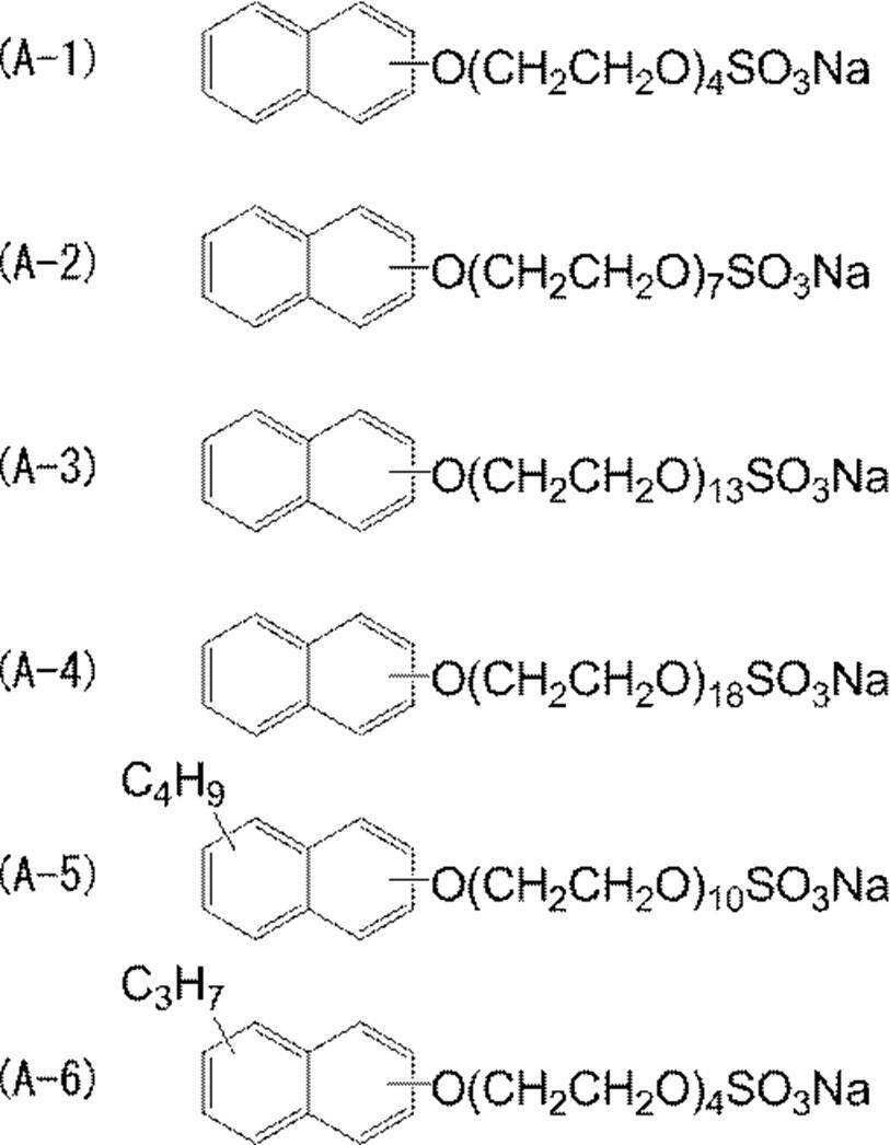

一般式(B)で表されるノニオン系活性剤は、1つのみ又は2種類以上を組み合わせて使用されうる。
以下に一般式(B)で表される化合物の具体例を示す。 In the compound represented by the general formula (B), the number (n) of oxyethylene groups which are repeating units is preferably 3 to 50, more preferably 5 to 30, and the number of oxypropylene groups which are repeating units. (M) is preferably 0 to 10, more preferably 0 to 5. When a plurality of oxyethylene groups and oxypropylene groups are linked to form a chain polyoxyalkylene chain, the oxyethylene group and the oxypropylene group form a block copolymer even if a random copolymer is formed. The number of oxypropylene groups is preferably 1 to 10 when the number of oxyethylene groups is 3 to 50. In one embodiment, the total number of oxyethylene groups and oxypropylene groups which are repeating units contained in the polyoxyalkylene chain is preferably 5 to 30. In one embodiment, when the polyoxyalkylene chain does not contain an oxyethylene group and contains only an oxypropylene group (that is, when n is 0), m is preferably 1 to 10.
The nonionic active agent represented by the general formula (B) can be used alone or in combination of two or more.
Specific examples of the compound represented by formula (B) are shown below.
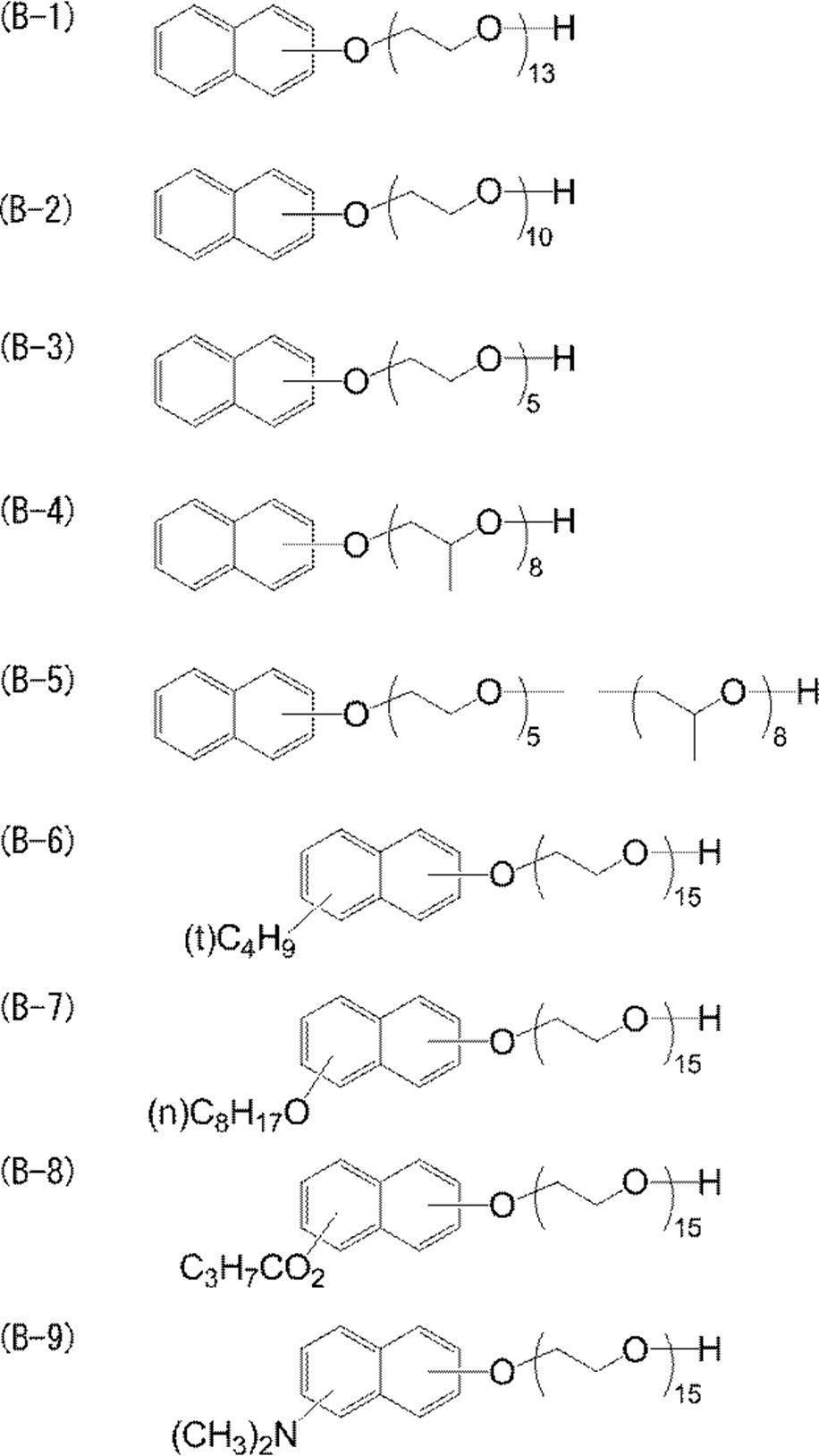
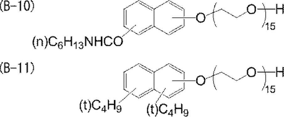
特定界面活性剤の現像液中における含有量は1質量%~10質量%の範囲内であり、2質量%~10質量%の範囲内で含むことが好ましい。含有量が1質量%以上であれば、現像性及び非露光部の画像記録層成分の溶解性が良好であり、10質量%以下とすることで得られる平版印刷版の耐刷性が良好となる。
既述のように、本発明において現像液とは現像補充液をも包含する意味で使用され、そのような観点から、本発明において使用される現像補充液における特定界面活性剤の含有量も1質量%~10質量%の範囲内であることが好ましい。 The said specific surfactant used for the developing solution used for this invention may use only one, and may use it in combination of 2 or more.
The content of the specific surfactant in the developer is in the range of 1% by mass to 10% by mass, and preferably in the range of 2% by mass to 10% by mass. If the content is 1% by mass or more, the developability and the solubility of the image recording layer components in the non-exposed area are good, and the lithographic printing plate obtained by making the content 10% by mass or less has good printing durability. Become.
As described above, in the present invention, the developing solution is used to include a developing replenisher. From such a viewpoint, the content of the specific surfactant in the developing replenisher used in the present invention is also 1. It is preferably in the range of 10% by mass to 10% by mass.
本発明において使用される現像液(現像開始液及び現像補充液)は、沸点が100℃~300℃の範囲にある有機溶剤の含有量は2質量%以下であり、既述のように当該有機溶剤を含有しなくてもよい。即ち、本発明に係る現像液に含有することを許容される有機溶剤は、沸点が100℃~300℃の範囲にある有機溶剤でありその許容される含有量の上限は2質量%である。
沸点が100℃より低いと有機溶剤は揮発しやすく、安定性が低下する傾向にあり、沸点が300℃を超える有機溶剤は現像液に含まれると廃液の濃縮がより困難になる。そのため上記有機溶剤以外の有機溶剤は、不可避不純物であるものを除いて、本発明に係る現像液には含有しないことが好ましい。 (Organic solvent)
The developer (development starter and developer replenisher) used in the present invention has an organic solvent content of 2 mass% or less with a boiling point in the range of 100 ° C. to 300 ° C. It does not need to contain a solvent. That is, the organic solvent allowed to be contained in the developer according to the present invention is an organic solvent having a boiling point in the range of 100 ° C. to 300 ° C., and the upper limit of the allowable content is 2% by mass.
When the boiling point is lower than 100 ° C., the organic solvent tends to volatilize and the stability tends to decrease, and when the organic solvent having a boiling point higher than 300 ° C. is contained in the developer, the concentration of the waste liquid becomes more difficult. Therefore, organic solvents other than the above organic solvents are preferably not contained in the developer according to the present invention except those which are inevitable impurities.
なお、後述するアルカリ剤のアミン類も、沸点が100℃~300℃の範囲内であれば、本発明における有機溶剤の範囲内である。 The organic solvent that may be included in the developer may be any organic solvent as long as the boiling point is in the range of 100 ° C. to 300 ° C., and a preferred example is 2-phenylethanol (boiling point: 219 ° C.). , 3-phenyl-1-propanol (boiling point: 238 ° C), 2-phenoxyethanol (boiling point: 244 to 255 ° C), benzyl alcohol (boiling point: 205 ° C), cyclohexanol (boiling point: 161 ° C), monoethanolamine (boiling point) : 170 ° C), diethanolamine (boiling point: 268 ° C), cyclohexanone (boiling point: 155 ° C), ethyl lactate (boiling point: 155 ° C), propylene glycol (boiling point: 187 ° C), ethylene glycol (boiling point: 198 ° C), γ- Butyrolactone (boiling point: 205 ° C.), N-methylpyrrolidone (boiling point: 202 ° C.), N-ethyl pyrrolidone Lydon (boiling point: 218 ° C), glycerin (boiling point: 290 ° C), propylene glycol monomethyl ether (boiling point: 120 ° C), ethylene glycol monomethyl ether (boiling point: 124 ° C), ethylene glycol monomethyl ether acetate (boiling point: 145 ° C), Examples include diethylene glycol dimethyl ether (boiling point: 162 ° C.) and glycerin (boiling point: 299 ° C.), and benzyl alcohol, diethanolamine, monoethanolamine, γ-butyrolactone, N-methylpyrrolidone, and N-ethylpyrrolidone are particularly preferable.
Note that the alkali amines described later are also within the range of the organic solvent in the present invention if the boiling point is in the range of 100 ° C to 300 ° C.
本発明の現像液は、pHが6.0~9.5であるが、pH調整剤を用いて、現像液のpHを調整してもよい。pH調製剤としては、クエン酸、りんご酸、酒石酸、安息香酸、フタル酸、p-エチル安息香酸、p-n-プロピル安息香酸、p-イソプロピル安息香酸、p-n-ブチル安息香酸、p-t-ブチル安息香酸、p-t-ブチル安息香酸、p-2-ヒドロキシエチル安息香酸、デカン酸、サリチル酸、3-ヒドロキシ-2-ナフトエ酸等の有機カルボン酸又はそれらの金属塩、アンモニウム塩などを含有することが好ましい。中でもクエン酸は緩衝剤としての機能があり、例えばクエン酸三ナトリウム、クエン酸三カリウムとして添加される。一般的には、現像液中に0.05~5質量%、より好ましくは0.3~3質量%の範囲で含有させる。 (Organic acid or its salt)
The developer of the present invention has a pH of 6.0 to 9.5, but the pH of the developer may be adjusted using a pH adjuster. Examples of pH adjusting agents include citric acid, malic acid, tartaric acid, benzoic acid, phthalic acid, p-ethylbenzoic acid, pn-propylbenzoic acid, p-isopropylbenzoic acid, pn-butylbenzoic acid, p- Organic carboxylic acids such as t-butylbenzoic acid, pt-butylbenzoic acid, p-2-hydroxyethylbenzoic acid, decanoic acid, salicylic acid, 3-hydroxy-2-naphthoic acid or their metal salts, ammonium salts, etc. It is preferable to contain. Among these, citric acid has a function as a buffer, and is added as trisodium citrate or tripotassium citrate, for example. Generally, it is contained in the developer in a range of 0.05 to 5% by mass, more preferably 0.3 to 3% by mass.
このようなキレート剤の現像液中の含有量は、現像液に使用される硬水の硬度及びその使用量に応じて変化するが、一般的には、使用時の現像液中における前記キレート剤の含有率は0.01質量%~5質量%の範囲内であることが好ましく、は0.01質量%~0.5質量%の範囲内であることがより好ましい。 The developer may contain a chelating agent for the divalent metal. Examples of divalent metals include magnesium and calcium. Examples of the chelating agent include Na 2 P 2 O 7 , Na 5 P 3 O 3 , Na 3 P 3 O 9 , Na 2 O 4 P (NaO 3 P) PO 3 Na 2 , and Calgon (sodium polymetaphosphate). Polydiamines; ethylenediaminetetraacetic acid, its potassium salt, and its sodium salt, diethylenetriaminepentaacetic acid, its potassium salt, and its sodium salt, triethylenetetraminehexaacetic acid, its potassium salt, and its sodium salt, hydroxyethylethylenediaminetrimethyl Acetic acid, its potassium salt, and its sodium salt, nitrilotriacetic acid, its potassium salt, and its sodium salt, 1,2-diaminocyclohexanetetraacetic acid, its potassium salt, and its sodium salt, and 1,3-diamino-2- Propanoltetraacetic acid, Aminopolycarboxylic acids such as potassium salt and sodium salt thereof; 2-phosphonobutane-1,2,4-tricarboxylic acid, potassium salt and sodium salt thereof, 2-phosphonobutanone-2,3,4-tricarboxylic acid Acid, its potassium salt, and its sodium salt, 1-phosphonoethane-1,2,2-tricarboxylic acid, its potassium salt, and its sodium salt, 1-hydroxyethane-1,1-diphosphonic acid, its potassium salt, and The sodium salt, and organic phosphonic acids such as aminotri (methylenephosphonic acid), its potassium salt, and its sodium salt.
The content of such a chelating agent in the developer varies depending on the hardness of the hard water used in the developer and the amount used, but generally, the content of the chelating agent in the developer at the time of use. The content is preferably in the range of 0.01% by mass to 5% by mass, more preferably in the range of 0.01% by mass to 0.5% by mass.
本発明の現像液には、消泡剤として、フッ素系消泡剤、シリコーン系消泡剤、アセチレンアルコール、及び/又はアセチレングリコールを含有させてもよい。 When an anionic surfactant is contained in the developer, the developer may further contain an antifoaming agent because it may be particularly easily foamed. When the developer contains an antifoaming agent, it is preferably contained in a proportion of 0.00001% by mass or more, more preferably in a proportion of about 0.0001% to 0.5% by mass with respect to the developer. preferable.
The developer of the present invention may contain a fluorine-based antifoaming agent, a silicone-based antifoaming agent, acetylene alcohol, and / or acetylene glycol as an antifoaming agent.
これらのうち、HLB1~9のフッ素系消泡剤、特にHLB1~4のフッ素系消泡剤が好ましい。上記のフッ素系消泡剤はそのまま、あるいは水その他の溶媒等と混合した乳濁液の形で現像液に添加される。 Examples of the fluorine-based antifoaming agent include compounds represented by the following formulas.
Of these, fluorine-based antifoaming agents of
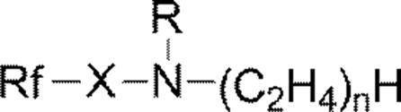

より具体的には、以下の一般式(A-1)、又は一般式(A-2)で示されるものが挙げられる。 The acetylene alcohol that can be used as an antifoaming agent is an unsaturated alcohol having an acetylene bond (triple bond) in the molecule. Acetylene glycol is also called alkynediol, and is an unsaturated glycol having an acetylene bond (triple bond) in the molecule.
More specific examples include those represented by the following general formula (A-1) or general formula (A-2).
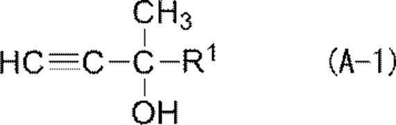
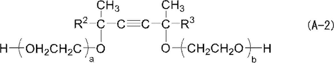
一般式(A-2)中、炭素原子数1~5の直鎖又は分岐鎖のアルキル基の例としては、メチル基、エチル基、イソプロピル基、イソブチル基、及びイソペンチル基が挙げられる。 (In general formula (A-2), R 2 and R 3 each independently represents a linear or branched alkyl group having 1 to 5 carbon atoms, and a and b are each independently an integer of 0 or more. Where a + b is in the range of 0-30.)
In the general formula (A-2), examples of the linear or branched alkyl group having 1 to 5 carbon atoms include a methyl group, an ethyl group, an isopropyl group, an isobutyl group, and an isopentyl group.
(1)プロパルギルアルコール
(2)プロパルギルカルビノール
(3)3,5-ジメチル-1-ヘキシン-3-オール
(4)3-メチル-1-ブチン-3-オール
(5)3-メチル-1-ペンチン-3-オール
(6)1,4-ブチンジオール
(7)2,5-ジメチル-3-ヘキシン-2,5-ジオール
(8)3,6-ジメチル-4-オクチン-3,6-ジオール
(9)2,4,7,9-テトラメチル-5-デシン-4,7-ジオール
(10)2,4,7,9-テトラメチル-5-デシン-4,7-ジオールの酸化エチレン付加物(下記構造) The following are mentioned as a further specific example of acetylene alcohol and acetylene glycol.
(1) propargyl alcohol (2) propargyl carbinol (3) 3,5-dimethyl-1-hexyn-3-ol (4) 3-methyl-1-butyn-3-ol (5) 3-methyl-1- Pentin-3-ol (6) 1,4-butynediol (7) 2,5-dimethyl-3-hexyne-2,5-diol (8) 3,6-dimethyl-4-octyne-3,6-diol (9) 2,4,7,9-Tetramethyl-5-decyne-4,7-diol (10) Addition of ethylene oxide to 2,4,7,9-tetramethyl-5-decyne-4,7-diol Things (the following structure)
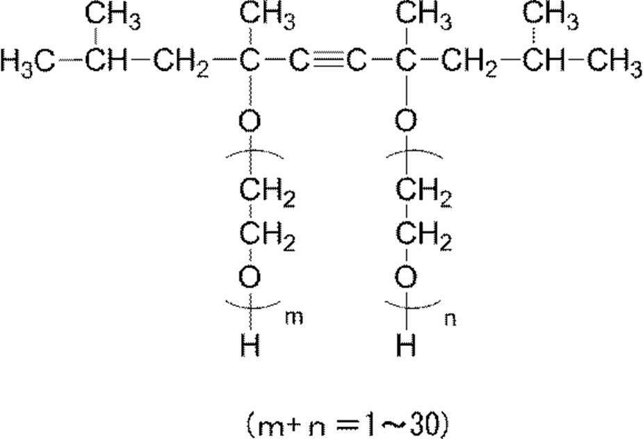
なお、本発明の方法が適用される感光性平版印刷版原版は、現像処理後に、水洗処理、及び不感脂化処理を行うため、現像液には版面保護を目的とした水溶性高分子化合物などは含有する必要はなく、現像廃液濃縮の効率向上の観点からも、水溶性高分子化合物を含有しないことが好ましい。 In addition to the above components, the developer according to the present invention may further contain, for example, components selected from the following as necessary: chelating agents, reducing agents, dyes, pigments, hard water softeners, and antiseptics. Agent.
The photosensitive lithographic printing plate precursor to which the method of the present invention is applied is subjected to a washing treatment and a desensitization treatment after the development treatment, so that a water-soluble polymer compound for the purpose of protecting the plate surface is used in the developer. Need not be contained, and from the viewpoint of improving the efficiency of developing waste liquid concentration, it is preferable not to contain a water-soluble polymer compound.
前述の現像液の残余の成分は水である。本発明に係る現像液は現像原液の形で調製されてもよい。つまり、本発明に係る現像液を、使用時よりも水の含有量を少なくした濃縮液として調製しておき、使用時に水で希釈するようにしておくことが運搬上有利である。この場合の濃縮度は各成分が分離や析出を起こさない程度であることが適当である。 〔water〕
The remaining component of the developer is water. The developer according to the present invention may be prepared in the form of a developing stock solution. That is, it is advantageous in terms of transportation to prepare the developer according to the present invention as a concentrated solution having a water content smaller than that in use and to dilute with water at the time of use. In this case, the degree of concentration is suitably such that each component does not cause separation or precipitation.
自動処理機を用いて現像する場合、処理量に応じて現像液が疲労してくるので、補充液又は新鮮な現像液を補充して現像処理能力を回復させてもよい。後述する本発明のリサイクル方法においてもこの補充方式が好ましく適用される。 The developer can be used as a development starter and a developer replenisher for the exposed photosensitive lithographic printing plate precursor, and is preferably applied to a developer bath of an automatic processor as described above.
When developing using an automatic processor, the developing solution becomes fatigued according to the amount of processing, and therefore the replenishing solution or fresh developing solution may be supplemented to restore the developing processing capability. This replenishment method is also preferably applied to the recycling method of the present invention described later.
なお、現像処理に先立ち、予め水洗処理を施し、保護層を除去しておく前処理工程を行ってもよい。 The development processing can be suitably carried out by an automatic processor equipped with a developer supply means (supply member) and a rubbing member.
Prior to the development process, a pre-treatment process may be performed in which a washing process is performed in advance and the protective layer is removed.
図2に示す自動現像装置1は、現像処理部10を有し、平版印刷版原版の搬送路12の搬送方向(矢印A)に沿って連続して形成された現像部14、水洗部16、不感脂化処理部18及び乾燥部20を有している。 An example of an automatic developing machine will be briefly described with reference to FIG.
The automatic developing
現像部14の内部には、現像液で満たされている現像槽24と、平版印刷版原版を現像槽24内部へ案内する挿入ローラー対241が設けられている。現像槽24の上部は遮蔽蓋242で覆われている。 The developing
A developing
現像槽24から搬出された平版印刷版は水洗部16において、水洗スプレー66により水洗水が供給され、版面等に残存する現像液が水洗除去され、その後、不感脂化処理部18にて、ガム液(不感脂化処理液)供給スプレー72により、版面に不感脂化処理液が供給される。
現像処理部10と乾燥部20との間に配置された仕切り板201にはスリット状挿通口202が設けられている。また、現像処理部10と乾燥部20との間の通路にはシャッター(不図示)が設けられ、平版印刷版原版が通路を通過していないとき、通路はシャッターにより閉じられている。
乾燥部20は、支持ローラー203、ダクト204、搬送ローラー対205、ダクト206、搬送ローラー対208がこの順に設けられている。ダクト204、205の先端にはスリット孔が設けられている。また、乾燥部20には図示しない温風供給手段(温風供給部材)、発熱手段(発熱部材)等の乾燥手段(乾燥部材)が設けられている。乾燥部20には排出口209が設けられ、乾燥手段により乾燥された平版印刷版は排出口209から排出される。 Inside the developing
The lithographic printing plate carried out from the developing
The
The drying
〔水洗工程(ii)〕
水洗工程は、現像液により、保護層、及び未露光部に対応する画像記録層が除去された版を、水により洗浄する工程である。水は、水道から直接供給される水でもよく、タンク中に保存された水でもよい。後述するように、本発明の現像処理廃液のリサイクル方法により得られた再生水をタンクに保存し、水洗工程に使用してもよい。
水洗水は、通常、水洗部16に備えられた水洗スプレー66より、現像処理工程を経た平版印刷版原版へスプレーされる。 The photosensitive lithographic printing plate precursor is subjected to a washing treatment step (ii) after being subjected to a development treatment step (i) [washing step (ii)].
[Washing step (ii)]
The water washing step is a step of washing the plate from which the protective layer and the image recording layer corresponding to the unexposed portion have been removed with a developer. The water may be water supplied directly from the water supply or water stored in a tank. As will be described later, the reclaimed water obtained by the recycling method of the development processing waste liquid of the present invention may be stored in a tank and used in the washing step.
The washing water is usually sprayed from the
〔不感脂化処理工程(iii)〕
現像処理及び水洗処理により未露光部(非画像)における画像記録層が除去された感光性平版印刷版は、特開昭54-8002号公報、同55-115045号公報、同59-58431号公報等に記載されているように、アラビアガムや澱粉誘導体等の水溶性高分子化合物を含む不感脂化液で後処理される。
即ち、不感脂化処理工程(iii)では、不感脂化処理液供給スプレー72により、版面に不感脂化処理液が供給され、非画像部領域の表面が不感脂化処理される。非画像部表面が不感脂化処理されることにより平版印刷版における非画像部表面の親水性が適切に維持され、非画像部における汚れの発生が抑制されることで平版印刷版の耐刷性がより向上する。さらに、画像部表面に不感脂化処理液が適用されることにより、画像部の耐傷性がより向上する。
本発明において不感脂化処理液の調製に用いられる水溶性高分子化合物としては、大豆多糖類、変性澱粉、アラビアガム、デキストリン、繊維素誘導体(例えばカルボキシメチルセルロース、カルボキシエチルセルロース、メチルセルロース等)及びその変性体、プルラン、ポリビニルアルコール及びその誘導体、ポリビニルピロリドン、ポリアクリルアミド及びアクリルアミド共重合体、ビニルメチルエーテル/無水マレイン酸共重合体、酢酸ビニル/無水マレイン酸共重合体、スチレン/無水マレイン酸共重合体などが挙げられる。水溶性高分子化合物の好ましい酸価は、0meq/g~3.0meq/gである。 The lithographic printing plate precursor that has undergone the development treatment step and the water washing treatment step is subjected to plate making by applying a desensitizing solution at the desensitizing treatment unit 18 [desensitizing step (iii)], and the lithographic printing plate Is obtained.
[Desensitizing treatment step (iii)]
Photosensitive lithographic printing plates from which the image recording layer in the unexposed area (non-image) has been removed by development processing and washing treatment are disclosed in JP-A Nos. 54-8002, 55-11545, and 59-58431. As described in the above, it is post-treated with a desensitizing solution containing a water-soluble polymer compound such as gum arabic and starch derivatives.
That is, in the desensitizing treatment step (iii), the desensitizing treatment liquid is supplied to the plate surface by the desensitizing treatment
Examples of the water-soluble polymer compound used in the preparation of the desensitizing solution in the present invention include soybean polysaccharide, modified starch, gum arabic, dextrin, fiber derivatives (eg, carboxymethylcellulose, carboxyethylcellulose, methylcellulose, etc.) and modified products thereof. Body, pullulan, polyvinyl alcohol and its derivatives, polyvinylpyrrolidone, polyacrylamide and acrylamide copolymer, vinyl methyl ether / maleic anhydride copolymer, vinyl acetate / maleic anhydride copolymer, styrene / maleic anhydride copolymer Etc. The preferred acid value of the water-soluble polymer compound is 0 meq / g to 3.0 meq / g.
本工程では、前記製版処理工程(i)において生じた製版処理廃液を、蒸発濃縮装置で、容量基準で濃縮度(濃縮後の製版処理廃液の量/濃縮前の製版処理廃液の量)が容量基準で1/2~1/10となるように、蒸発濃縮する。
以下、本発明に係る蒸発濃縮工程について説明する。
蒸発濃縮装置は、廃液を、減圧を行わずに加熱又は減圧下で加熱し、蒸発する水分と残留する濃縮物(スラリー)とに分離する蒸発釜を少なくとも具備する。好ましい実施態様においては、蒸発濃縮装置は、蒸発釜において、有機溶剤を含有していてもよい水蒸気として分離された水分を導入し、冷却により凝縮して再生水とする冷却釜をさらに具備する。 [Evaporation and concentration process]
In this step, the plate making waste liquid produced in the plate making step (i) is concentrated by an evaporation concentrator on a volume basis with a concentration (amount of plate making waste after concentration / amount of plate making waste before concentration) in volume. Evaporate and concentrate to 1/2 to 1/10 on the basis.
Hereinafter, the evaporation concentration step according to the present invention will be described.
The evaporative concentration apparatus includes at least an evaporating kettle that heats the waste liquid without depressurization or heats it under reduced pressure to separate the evaporated water and the remaining concentrate (slurry). In a preferred embodiment, the evaporative concentration apparatus further includes a cooling kettle that introduces moisture separated as water vapor that may contain an organic solvent into the evaporating kettle and condenses it by cooling to regenerate water.
減圧手段の例としては、一般的な水封式や油回転式、ダイヤフラム式等の機械的真空ポンプ、油や水銀を用いた拡散ポンプ、多段ターボ圧縮機、往復圧縮機、ねじ圧縮機等の圧縮機、アスピレータが挙げられるが、この中ではアスピレータがメンテナンス性、コストの点で好ましい。
減圧条件としては、例えば圧力を、666.6Pa(5mmHg)~13332.2Pa(100mmHg)、好ましくは666.6Pa(5mmHg)~3999.7Pa(30mmHg)とするように減圧することが挙げられる。
加熱条件は、水流ポンプや真空ポンプで得られやすい圧力である666.6Pa~13332.2Paに対応した温度域が選択される。具体的には20℃~80℃の範囲であり、より好ましくは25℃~45℃の範囲である。
高温で蒸留することにより濃縮を行うと、多くの電力を要する。しかし、上記のように濃縮を減圧下で行うことにより加熱温度を低くし、使用電力を抑制することができる。 The concentration of the waste liquid is preferably performed by a method in which the inside of the evaporation pot is decompressed by a decompression means (a decompression member) and the waste liquid is concentrated by heating. This is because according to this method, the boiling point of the waste liquid is lowered, and the waste liquid can be evaporated and concentrated at a lower temperature than under atmospheric pressure. By using the depressurization means, the waste liquid can be concentrated more safely, and since the concentration is performed at a lower temperature, there is an advantage that the evaporating pot, the waste liquid, and the waste liquid concentrate are not easily affected by heat.
Examples of pressure reducing means include general water seal type, oil rotary type, diaphragm type mechanical vacuum pumps, diffusion pumps using oil and mercury, multistage turbo compressors, reciprocating compressors, screw compressors, etc. Although a compressor and an aspirator are mentioned, an aspirator is preferable in terms of maintainability and cost.
Examples of the depressurization condition include depressurization such that the pressure is 666.6 Pa (5 mmHg) to 13332.2 Pa (100 mmHg), preferably 666.6 Pa (5 mmHg) to 3999.7 Pa (30 mmHg).
As the heating condition, a temperature range corresponding to 666.6 Pa to 13332.2 Pa, which is a pressure easily obtained with a water pump or a vacuum pump, is selected. Specifically, it is in the range of 20 ° C to 80 ° C, more preferably in the range of 25 ° C to 45 ° C.
When concentration is performed by distillation at a high temperature, a lot of electric power is required. However, by performing the concentration under reduced pressure as described above, the heating temperature can be lowered and the power consumption can be suppressed.
本実施形態に使用される廃液濃縮装置として、ヒートポンプ方式濃縮装置XR-2000、XR-5000(いずれも商品名、富士フイルムグローバルグラフィックシステムズ株式会社)、加熱方式のコスモテック社製フレンドリーシリーズ(商品名)などの市販品を用いてもよい。 When evaporating and concentrating the platemaking process waste liquid in the evaporation concentrator, the platemaking process waste liquid is heated by a heating means in an evaporation kettle so that the degree of concentration (the amount of the platemaking process waste liquid after concentration / plate making process before concentration) Evaporation is concentrated so that the amount of waste liquid is 1/2 to 1/10 of the volume. Here, when the concentration is 1/2 or more, the amount of waste liquid to be processed is more effectively reduced, and when the concentration is 1/10 or less, the inside of the evaporation pot of the waste
As waste liquid concentrators used in this embodiment, heat pump type concentrators XR-2000 and XR-5000 (both are trade names, FUJIFILM Global Graphic Systems Co., Ltd.), heating series friendly series (product names) ) And other commercial products may be used.
本工程では、前記蒸発濃縮において生じた水蒸気を、冷却により凝縮して再生水を生成する。
既述のように、蒸発濃縮工程において、廃液の加熱濃縮をヒートポンプで行う場合には、ヒートポンプの吸熱部で冷却された水蒸気が液状となり再生水が得られる。即ち、前記蒸発濃縮工程において、再生水が生成される。
また、廃液の加熱濃縮を電熱器等の公知の加熱手段を用いて行った場合には、水蒸気を前記蒸発濃縮装置より導出し、冷却手段(冷却部材)を用いて水蒸気を凝縮して再生水を生成することができる。冷却手段としては、公知の水冷クーラーなどを適宜使用すればよい。 [Reclaimed water generation process]
In this step, the water vapor generated in the evaporation concentration is condensed by cooling to generate reclaimed water.
As described above, when the waste liquid is heated and concentrated by the heat pump in the evaporation and concentration step, the water vapor cooled by the heat absorption part of the heat pump becomes liquid to obtain reclaimed water. That is, reclaimed water is generated in the evaporative concentration step.
When the waste liquid is heated and concentrated using a known heating means such as an electric heater, the water vapor is led out from the evaporating and concentrating device, and the water vapor is condensed using a cooling means (cooling member). Can be generated. As the cooling means, a known water-cooled cooler or the like may be used as appropriate.
また、後述する本発明のリサイクル方法におけるように、再生水を現像浴に希釈水などとして供給したり、水洗部16における水洗水として供給したりして、再利用することも好ましい。 The reclaimed water obtained as described above is reclaimed water having a low BOD and COD value. When the developer used in the present invention is used, the BOD value of the reclaimed water is approximately 250 mg / L or less and the COD value of the reclaimed water is 200 mg / L or less. Therefore, the excess reclaimed water may be discharged as it is into the general waste water. However, when the reclaimed water contains an organic solvent or the like, a treatment with activated sludge or the like is performed before discharge.
Further, as in the recycling method of the present invention to be described later, it is also preferable to recycle the recycled water by supplying it to the developing bath as dilution water or by supplying it as rinsing water in the
本発明の廃液濃縮方法が適用される現像処理廃液を生じる感光性平版印刷版原版の製版において、支持体上に以下に詳述するネガ型の画像記録層を有する感光性平版印刷版原版を露光後、i)ナフタレン骨格を有するアニオン性界面活性剤及びナフタレン骨格を有するノニオン性界面活性剤からなる群より選ばれる少なくとも一つの界面活性剤を1質量%~10質量%含有し、沸点が100℃~300℃の範囲である有機溶剤の含有量が2質量%以下であり、pHが6.0~9.5である処理液により、現像処理する現像処理工程(i)、水洗工程(ii)及び不感脂化液による非画像部の不感脂化処理工程(iii)が行われるのは既述の通りである。
本発明の一実施形態であるリサイクル方法は、前記現像処理工程において生じた現像処理廃液を、蒸発濃縮装置で、濃縮前の現像処理廃液容量に対する濃縮後の現像処理廃液容量の比(濃縮度、すなわち容量基準における(濃縮後の現像処理廃液の量)/(濃縮前の現像処理廃液の量))が1/2~1/10となるように、蒸発濃縮する工程、前記蒸発濃縮工程において生じた水蒸気を冷却により凝縮して再生水を生成させる再生水生成工程、及び、前記再生水を、前記自動現像機に供給する再生水供給工程、を含む。
即ち、本発明のリサイクル方法は、前記製版処理工程、廃液の蒸発濃縮工程、及び再生水生成工程に加え、さらに、再生水供給工程を有するものである。
本発明のリサイクル方法においては、生成された再生水は、補充水タンクなどに供給され、自動現像機内に配置された現像浴内で所定倍率に現像補充液を希釈する希釈水として使用されてもよく、予め、現像補充液に混合され、現像補充液を所定の倍率に希釈するために用いられてもよい。また再生水は、自動現像装置1の水洗部14に供給され、水洗水として使用されてもよい。また再生水は不感脂化処理部16における不感脂化処理液槽に供給されてもよい。 [Recycling method of plate making waste liquid for photosensitive lithographic printing plate]
In the plate making of a photosensitive lithographic printing plate precursor for producing a development processing waste liquid to which the waste liquid concentration method of the present invention is applied, the photosensitive lithographic printing plate precursor having a negative image recording layer described in detail below is exposed on the support. Thereafter, i) containing 1% by mass to 10% by mass of at least one surfactant selected from the group consisting of an anionic surfactant having a naphthalene skeleton and a nonionic surfactant having a naphthalene skeleton, and having a boiling point of 100 ° C. Development processing step (i) and water washing step (ii) for developing with a processing solution having a content of an organic solvent in the range of ˜300 ° C. of 2% by mass or less and a pH of 6.0 to 9.5 As described above, the desensitization treatment step (iii) of the non-image area with the desensitizing liquid is performed.
In the recycling method according to an embodiment of the present invention, the development processing waste liquid generated in the development processing step is subjected to a ratio of the development processing waste liquid volume after concentration to the development processing waste liquid volume before concentration (concentration, That is, it occurs in the evaporation concentration step and the evaporation concentration step so that (amount of development processing waste liquid after concentration) / (amount of development processing waste liquid before concentration)) is 1/2 to 1/10 on a volume basis. A reclaimed water generating step of condensing the water vapor by cooling to generate reclaimed water, and a reclaimed water supply step of supplying the reclaimed water to the automatic processor.
That is, the recycling method of the present invention further includes a reclaimed water supply step in addition to the plate making process, the waste liquid evaporation and concentration step, and the reclaimed water generation step.
In the recycling method of the present invention, the generated reclaimed water may be supplied to a replenishing water tank or the like and used as diluting water for diluting the developing replenisher at a predetermined magnification in a developing bath disposed in an automatic processor. The developer replenisher may be mixed in advance and used to dilute the developer replenisher to a predetermined magnification. The reclaimed water may be supplied to the
以下、図面を参照して本発明に係る実施形態の一例について説明する。
ある例示的実施形態に係る現像処理廃液のリサイクル方法では、図1に示すように、感光性平版印刷版の製版処理に伴って自動現像機10から排出される現像液の廃液を中間タンク20に貯蔵し、該中間タンク20より送られた廃液を、廃液濃縮装置30により減圧を行わずに加熱又は減圧下で加熱し、蒸発した水分と残留した濃縮物(スラリー)とに分離する。廃液濃縮装置30で水蒸気として分離された水分を、冷却により凝縮して得られた再生水は再生水タンク50に導入される。また、廃液濃縮装置30で濃縮された廃液は廃液回収タンク40に回収される。廃液タンク40への濃縮された廃液の移送は、好ましくはポンプで加圧することにより行われる。 Specific examples of the apparatus that can be suitably used in the waste liquid concentration method and the recycling method of the present invention include, for example, a planographic printing plate making process waste liquid reduction apparatus described in Japanese Patent No. 4774124, and Japanese Patent Application Laid-Open No. 2011-90282. The waste liquid processing apparatus described in the gazette etc. is mentioned.
Hereinafter, an exemplary embodiment according to the present invention will be described with reference to the drawings.
In the recycling method of the development processing waste liquid according to an exemplary embodiment, as shown in FIG. 1, the waste liquid of the developer discharged from the
前記ポンプの駆動は、前記圧力計で測定された圧力値に応じて制御され、前記ポンプの駆動により回収された再生水は前記補充水タンク80から前記自動現像装置10に供給される。また、自動現像機10には、現像補充液タンク70から現像補充液が供給される。 In the recycling method of the development processing waste liquid according to the exemplary embodiment, a
The driving of the pump is controlled according to the pressure value measured by the pressure gauge, and the reclaimed water collected by driving the pump is supplied from the replenishing
このシステムで得られる再生水はBOD、COD値の低い再生水である。本発明で用いられる現像液を使用した場合、前記システムにより得られる再生水のBOD値はおおよそ250mg/L以下、再生水のCOD値はおおよそ200mg/L以下となるので、前記再生水は自動現像機における蒸発補正用の希釈水、現像補充液の希釈水、版を洗浄するリンス水、又は、自動現像機の洗浄水として用いることができる他、余剰の再生水はそのまま一般排水に放出してもよい。 The reclaimed water obtained by this system may contain an organic solvent as long as it is 0.5% or less based on the volume.
The reclaimed water obtained by this system is reclaimed water having a low BOD and COD value. When the developer used in the present invention is used, the BOD value of reclaimed water obtained by the system is approximately 250 mg / L or less, and the COD value of reclaimed water is approximately 200 mg / L or less. Therefore, the reclaimed water is evaporated in an automatic processor. It can be used as a dilution water for correction, a dilution water for a developing replenisher, a rinsing water for washing a plate, or a washing water for an automatic developing machine. In addition, excess reclaimed water may be discharged as it is into general waste water.
また、複数の自動現像機から発生する製版処理廃液が、一つの廃液濃縮装置に集められ、得られた再生水が、複数の自動現像機に希釈水又はリンス水として供給されてもよい。
このように再生水を補充水として利用することで、希釈水などを新たに自動現像機に供給することなく、適切に製版処理される平版印刷版原版の処理量が増加する。 In the present invention, the developer replenisher is diluted and supplied to the developing bath of the
Further, the platemaking process waste liquid generated from a plurality of automatic processors may be collected in one waste liquid concentrator, and the obtained reclaimed water may be supplied as dilution water or rinse water to the plurality of automatic processors.
By using the reclaimed water as the replenishing water in this way, the processing amount of the lithographic printing plate precursor that is appropriately subjected to the plate making process is increased without supplying dilution water or the like to the automatic processor.
本発明に係る感光性平版印刷版原版は、支持体上に(a)赤外線吸収染料、(b)重合開始剤、及び(c)重合性化合物、を含有するラジカル重合性の画像記録層と、保護層と、をこの順に有する。
画像記録層に含まれる各成分について順次説明する。 [Photosensitive planographic printing plate precursor]
A photosensitive lithographic printing plate precursor according to the present invention comprises a radically polymerizable image recording layer containing (a) an infrared absorbing dye, (b) a polymerization initiator, and (c) a polymerizable compound on a support; And a protective layer in this order.
Each component included in the image recording layer will be described sequentially.
赤外線吸収染料は、吸収した赤外線を熱に変換する機能と赤外線により励起して後述のラジカル重合開始剤に電子移動及び/又はエネルギー移動する機能を有する。本発明において使用される赤外線吸収染料は、波長760~1200nmに吸収極大を有する染料である。 [(A) Infrared absorbing dye]
The infrared absorbing dye has a function of converting the absorbed infrared light into heat and a function of being excited by the infrared light and transferring electrons and / or energy to a radical polymerization initiator described later. The infrared absorbing dye used in the present invention is a dye having an absorption maximum at a wavelength of 760 to 1200 nm.
これらの染料のうち特に好ましいものとしては、シアニン色素、スクアリリウム色素、ピリリウム塩、ニッケルチオレート錯体、インドレニンシアニン色素が挙げられる。更に、シアニン色素やインドレニンシアニン色素が好ましく、特に好ましい例として下記一般式(e)で示されるシアニン色素が挙げられる。 As the dye, commercially available dyes and known dyes described in documents such as “Dye Handbook” (edited by the Society for Synthetic Organic Chemistry, published in 1970) can be used. Specifically, dyes such as azo dyes, metal complex azo dyes, pyrazolone azo dyes, naphthoquinone dyes, anthraquinone dyes, phthalocyanine dyes, carbonium dyes, quinoneimine dyes, methine dyes, cyanine dyes, squarylium dyes, pyrylium salts, metal thiolate complexes Is mentioned.
Particularly preferred among these dyes are cyanine dyes, squarylium dyes, pyrylium salts, nickel thiolate complexes, and indolenine cyanine dyes. Further, cyanine dyes and indolenine cyanine dyes are preferred, and particularly preferred examples include cyanine dyes represented by the following general formula (e).

なかでもフェニル基が好ましい(-NPh2)。X2は酸素原子又は硫黄原子を示し、L1は、炭素原子数1~12の炭化水素基、ヘテロアリール基、又はヘテロ原子を含む炭素原子数1~12の炭化水素基を示す。なお、ここでヘテロ原子とは、N、S、O、ハロゲン原子、又はSeを示す。以下に示す基において、Xa-は後述するZa-と同様に定義され、Raは、水素原子、アルキル基、アリール基、置換又は無置換のアミノ基、及びハロゲン原子からなる群より選択される置換基を表す。 In general formula (e), X 1 represents a hydrogen atom, a halogen atom, —N (R 9 ) (R 10 ), —X 2 -L 1 or a group shown below. Here, R 9 and R 10 may be the same or different, and may have a substituent, an aryl group having 6 to 10 carbon atoms, an alkyl group having 1 to 8 carbon atoms, or a hydrogen atom. R 9 and R 10 may be bonded to each other to form a ring.
Of these, a phenyl group is preferred (—NPh 2 ). X 2 represents an oxygen atom or a sulfur atom, and L 1 represents a hydrocarbon group having 1 to 12 carbon atoms, a heteroaryl group, or a hydrocarbon group having 1 to 12 carbon atoms including a hetero atom. In addition, a hetero atom shows N, S, O, a halogen atom, or Se here. In the group shown below, Xa - has Za described later - is defined as for, Ra represents a hydrogen atom, an alkyl group, an aryl group, a substituted or unsubstituted amino group, and substitutions selected from the group consisting of halogen atoms Represents a group.

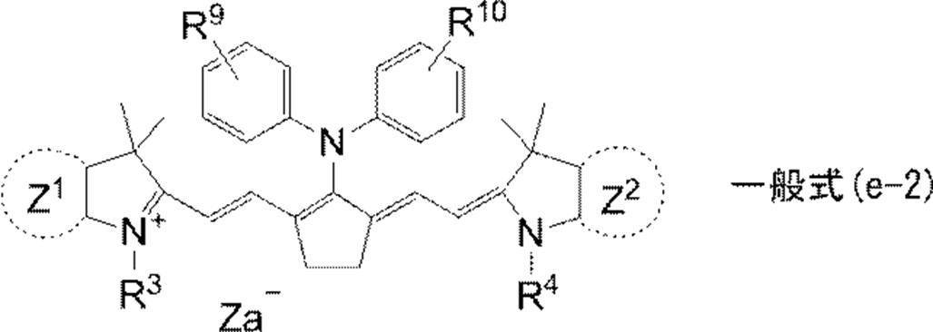
R3及びR4はそれぞれ独立に置換基を有していてもよい炭素数20以下の炭化水素基を表す。好ましい置換基としては、炭素原子数12個以下のアルコキシ基、カルボキシ基、スルホ基が挙げられる。
R9及びR10はそれぞれ独立に水素原子又は置換基を有していてもよいアルコキシ基を表す。Za-は、電荷の中和が必要な場合に存在する対アニオンを表す。好ましいZa-は、画像記録層塗布液の保存安定性から、ハロゲン化物イオン、過塩素酸イオン、テトラフルオロボレートイオン、ヘキサフルオロホスフェートイオン、及びスルホン酸イオンであり、特に好ましくは、過塩素酸イオン、ヘキサフルオロホスフェートイオン、及びアリールスルホン酸イオンである。 In the formula, Z 1 and Z 2 each independently represent an aromatic ring or a heteroaromatic ring which may have a substituent. Preferred aromatic rings include a benzene ring and a naphthalene ring. Preferred substituents include a hydrocarbon group having 12 or less carbon atoms, a halogen atom, an alkoxy group having 12 or less carbon atoms, a hydrocarbon group having 12 or less carbon atoms, and 12 carbon atoms. Most preferred are not more than alkoxy groups.
R 3 and R 4 each independently represent a hydrocarbon group having 20 or less carbon atoms which may have a substituent. Preferred substituents include alkoxy groups having 12 or less carbon atoms, carboxy groups, and sulfo groups.
R 9 and R 10 each independently represent a hydrogen atom or an alkoxy group which may have a substituent. Za − represents a counter anion present when charge neutralization is required. Preferred Za − is a halide ion, a perchlorate ion, a tetrafluoroborate ion, a hexafluorophosphate ion, and a sulfonate ion, particularly preferably a perchlorate ion, in view of the storage stability of the image recording layer coating solution. , Hexafluorophosphate ions, and aryl sulfonate ions.
また特開平5-5005号公報の段落番号[0008]~[0009]、特開2001-222101号公報の段落番号[0022]~[0025]に記載の化合物も好ましい。 Specific examples of the cyanine dye represented by formula (e) that can be suitably used include compounds described in paragraphs [0017] to [0019] of JP-A No. 2001-133969, JP-A No. 2002-023360. Examples include the compounds described in paragraph numbers [0016] to [0021] of JP-A No. 2002-040638, paragraph numbers [0012] to [0037] of JP-A No. 2002-040638, and preferably paragraph Nos. Of JP-A No. 2002-278057. 0034] to [0041], and compounds described in JP-A-2008-195018, paragraphs [0080] to [0086], and most preferably, JP-A-2007-90850, paragraphs [0035]-[ 0043] can be mentioned.
In addition, compounds described in paragraph numbers [0008] to [0009] of JP-A No. 5-5005 and paragraph numbers [0022] to [0025] of JP-A No. 2001-222101 are also preferable.
(b)ラジカル発生剤は、(c)重合性化合物の重合を開始及び/又は促進する化合物である。ラジカル発生剤としては、公知の熱重合開始剤、結合解離エネルギーの小さな結合を有する化合物、光重合開始剤などを使用することができる。
ラジカル発生剤の例としては、(1)有機ハロゲン化物、(2)カルボニル化合物、(3)アゾ化合物、(4)有機過酸化物、(5)メタロセン化合物、(6)アジド化合物、(7)ヘキサアリールビイミダゾール化合物、(8)有機ホウ酸塩化合物、(9)ジスルホン化合物、(10)オキシムエステル化合物、(11)オニウム塩化合物などが挙げられる。 [(B) Radical generator]
The (b) radical generator is a compound that initiates and / or accelerates the polymerization of the (c) polymerizable compound. As the radical generator, a known thermal polymerization initiator, a compound having a bond with a small bond dissociation energy, a photopolymerization initiator, or the like can be used.
Examples of radical generators are (1) organic halides, (2) carbonyl compounds, (3) azo compounds, (4) organic peroxides, (5) metallocene compounds, (6) azide compounds, (7) Examples include hexaarylbiimidazole compounds, (8) organic borate compounds, (9) disulfone compounds, (10) oxime ester compounds, and (11) onium salt compounds.
(2)カルボニル化合物としては、特開2008-195018号公報の段落番号[0024]に記載の化合物が好ましい。
(3)アゾ化合物としては、例えば、特開平8-108621号公報に記載のアゾ化合物等を使用することができる。
(4)有機過酸化物としては、例えば、特開2008-195018号公報の段落番号[0025]に記載の化合物が好ましい。 (1) As the organic halide, compounds described in paragraph numbers [0022] to [0023] of JP-A-2008-195018 are preferable.
(2) As the carbonyl compound, compounds described in paragraph [0024] of JP-A-2008-195018 are preferred.
(3) As the azo compound, for example, an azo compound described in JP-A-8-108621 can be used.
(4) As the organic peroxide, for example, compounds described in paragraph [0025] of JP-A-2008-195018 are preferable.
(6)アジド化合物としては、2,6-ビス(4-アジドベンジリデン)-4-メチルシクロヘキサノン等の化合物を挙げることができる。 (5) As the metallocene compound, for example, the compound described in paragraph [0026] of JP-A-2008-195018 is preferable.
(6) Examples of the azide compound include compounds such as 2,6-bis (4-azidobenzylidene) -4-methylcyclohexanone.
画像記録層に用いる重合性化合物は、少なくとも一個のエチレン性不飽和二重結合を有する付加重合性化合物であり、末端エチレン性不飽和結合を少なくとも1個、好ましくは2個以上有する化合物から選ばれる。これらは、例えばモノマー、プレポリマー、すなわち2量体、3量体及びオリゴマー、又はそれらの混合物などの化学的形態をとりうる。 [(C) polymerizable compound]
The polymerizable compound used in the image recording layer is an addition polymerizable compound having at least one ethylenically unsaturated double bond, and is selected from compounds having at least one terminal ethylenically unsaturated bond, preferably two or more. . These can take chemical forms such as monomers, prepolymers, ie dimers, trimers and oligomers, or mixtures thereof.
画像記録層には、画像記録層の膜強度を向上させるため、バインダーポリマーを用いてもよい。バインダーポリマーとしては、従来公知のものを制限なく使用でき、皮膜性を有するポリマーが好ましい。なかでも、アクリル樹脂、ポリビニルアセタール樹脂、ポリウレタン樹脂が好ましい。 [(D) Binder polymer]
In the image recording layer, a binder polymer may be used in order to improve the film strength of the image recording layer. As the binder polymer, any conventionally known polymer can be used without limitation, and a polymer having a film property is preferable. Of these, acrylic resins, polyvinyl acetal resins, and polyurethane resins are preferable.
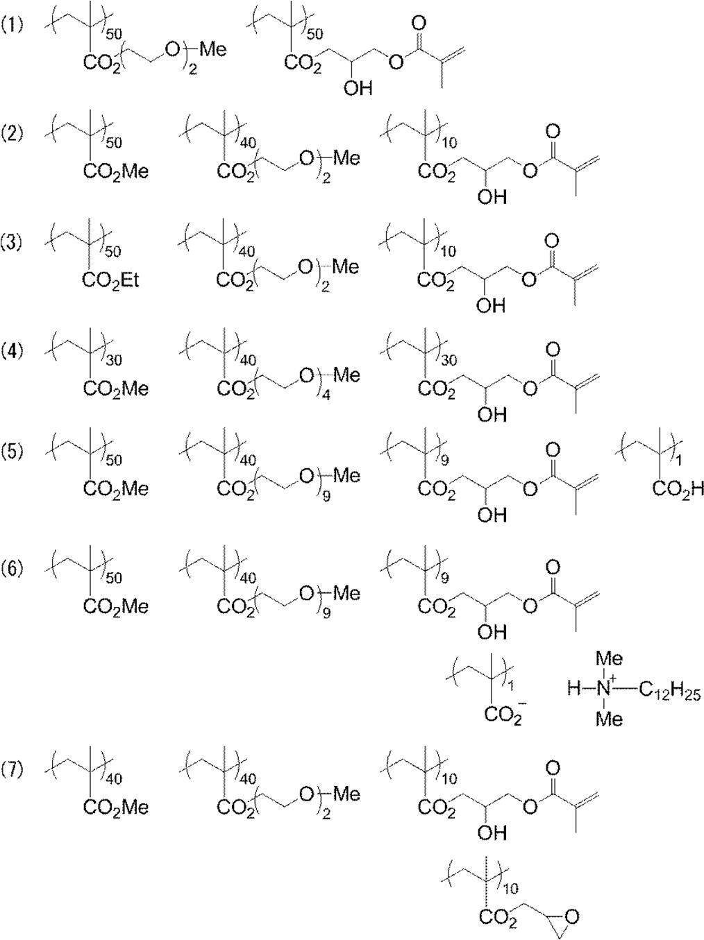
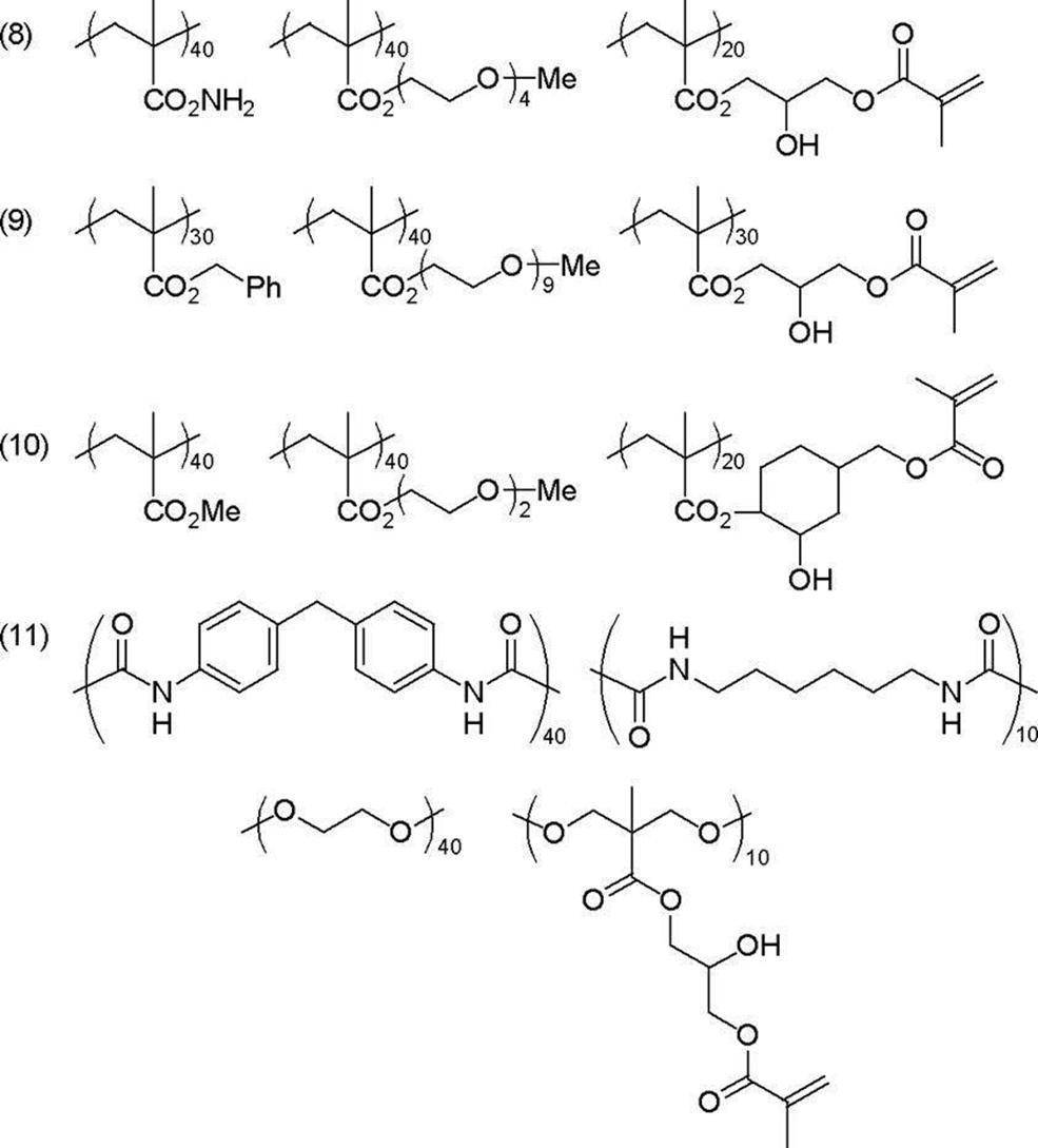
本発明に用いられる高分子化合物は、主鎖が3つ以上に分岐している星型ポリマーであり、下記の一般式(P-1)で表される如き高分子化合物である。 [Star polymer]
The polymer compound used in the present invention is a star polymer having a main chain branched into three or more, and is a polymer compound represented by the following general formula (P-1).
星型ポリマーは、上記の如き主鎖構造であるポリマー鎖を有し、ポリマー鎖が側鎖としてポリエチレンオキシ基及びポリプロピレンオキシ基から選択される少なくとも一つを有する高分子化合物である。 [Polymer part]
The star polymer is a polymer compound having a polymer chain having the main chain structure as described above and having at least one selected from a polyethyleneoxy group and a polypropyleneoxy group as a side chain.

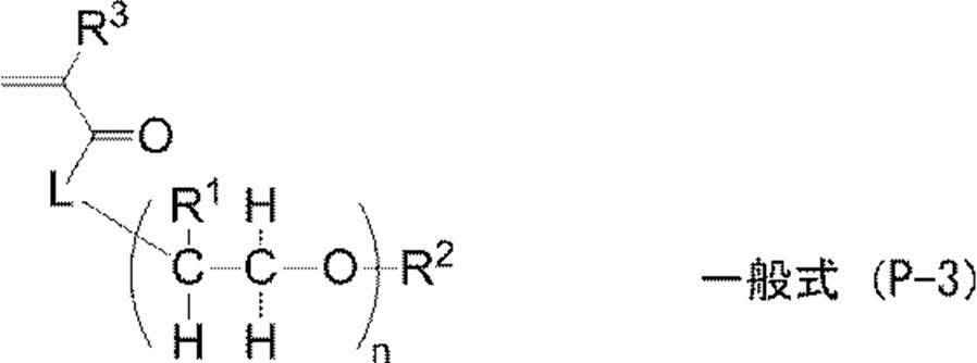

高分子化合物の保存安定性及び皮膜強度の観点より、(メタ)アクリル基が好ましい。 As the ethylenically unsaturated group, a (meth) acryl group, a vinyl group, an allyl group and the like are preferable, and these groups can be introduced into a polymer by a polymer reaction or copolymerization. For example, reaction between an acrylic polymer having a carboxy group in the side chain and glycidyl methacrylate, reaction between a polymer having an epoxy group and an ethylenically unsaturated group-containing carboxylic acid such as methacrylic acid, or a polymer having a hydroxy group and an isocyanate group Reaction with methacrylate can be used.
From the viewpoints of storage stability and film strength of the polymer compound, a (meth) acryl group is preferred.
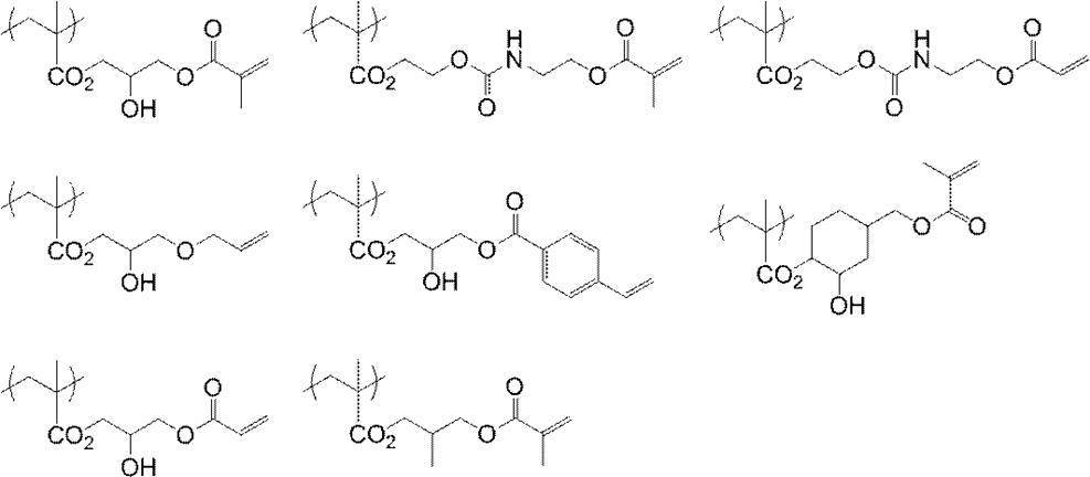
(m2)アクリル酸メチル、アクリル酸エチル、アクリル酸プロピル、アクリル酸ブチル、アクリル酸アミル、アクリル酸ヘキシル、アクリル酸オクチル、アクリル酸ベンジル、アクリル酸-2-クロロエチル、グリシジルアクリレート等のアルキルアクリレート。
(m3)メタクリル酸メチル、メタクリル酸エチル、メタクリル酸プロピル、メタクリル酸ブチル、メタクリル酸アミル、メタクリル酸ヘキシル、メタクリル酸シクロヘキシル、メタクリル酸ベンジル、メタクリル酸-2-クロロエチル、グリシジルメタクリレート等のアルキルメタクリレート。
(m4)アクリルアミド、メタクリルアミド、N-メチロールアクリルアミド、N-エチルアクリルアミド、N-ヘキシルメタクリルアミド、N-シクロヘキシルアクリルアミド、N-ヒドロキシエチルアクリルアミド、N-フェニルアクリルアミド、N-ニトロフェニルアクリルアミド、N-エチル-N-フェニルアクリルアミド等のアクリルアミド若しくはメタクリルアミド。
(m5)エチルビニルエーテル、2-クロロエチルビニルエーテル、ヒドロキシエチルビニルエーテル、プロピルビニルエーテル、ブチルビニルエーテル、オクチルビニルエーテル、フェニルビニルエーテル等のビニルエーテル類。
(m6)ビニルアセテート、ビニルクロロアセテート、ビニルブチレート、安息香酸ビニル等のビニルエステル類。
(m7)スチレン、α-メチルスチレン、メチルスチレン、クロロメチルスチレン等のスチレン類。
(m8)メチルビニルケトン、エチルビニルケトン、プロピルビニルケトン、フェニルビニルケトン等のビニルケトン類。
(m9)エチレン、プロピレン、イソブチレン、ブタジエン、イソプレン等のオレフィン類。
(m10)N-ビニルピロリドン、アクリロニトリル、メタクリロニトリル等。
(m11)マレイミド、N-アセチルメタクリルアミド、N-プロピオニルメタクリルアミド、N-(p-クロロベンゾイル)メタクリルアミド等の不飽和イミド。 (M1) Acrylic acid esters and methacrylic acid esters having an aliphatic hydroxy group such as 2-hydroxyethyl acrylate or 2-hydroxyethyl methacrylate.
(M2) Alkyl acrylates such as methyl acrylate, ethyl acrylate, propyl acrylate, butyl acrylate, amyl acrylate, hexyl acrylate, octyl acrylate, benzyl acrylate, 2-chloroethyl acrylate, and glycidyl acrylate.
(M3) Alkyl methacrylates such as methyl methacrylate, ethyl methacrylate, propyl methacrylate, butyl methacrylate, amyl methacrylate, hexyl methacrylate, cyclohexyl methacrylate, benzyl methacrylate, 2-chloroethyl methacrylate and glycidyl methacrylate.
(M4) Acrylamide, methacrylamide, N-methylolacrylamide, N-ethylacrylamide, N-hexylmethacrylamide, N-cyclohexylacrylamide, N-hydroxyethylacrylamide, N-phenylacrylamide, N-nitrophenylacrylamide, N-ethyl- Acrylamide or methacrylamide such as N-phenylacrylamide.
(M5) Vinyl ethers such as ethyl vinyl ether, 2-chloroethyl vinyl ether, hydroxyethyl vinyl ether, propyl vinyl ether, butyl vinyl ether, octyl vinyl ether, and phenyl vinyl ether.
(M6) Vinyl esters such as vinyl acetate, vinyl chloroacetate, vinyl butyrate and vinyl benzoate.
(M7) Styrenes such as styrene, α-methylstyrene, methylstyrene, chloromethylstyrene.
(M8) Vinyl ketones such as methyl vinyl ketone, ethyl vinyl ketone, propyl vinyl ketone, and phenyl vinyl ketone.
(M9) Olefins such as ethylene, propylene, isobutylene, butadiene and isoprene.
(M10) N-vinylpyrrolidone, acrylonitrile, methacrylonitrile and the like.
(M11) Unsaturated imides such as maleimide, N-acetylmethacrylamide, N-propionylmethacrylamide, N- (p-chlorobenzoyl) methacrylamide.
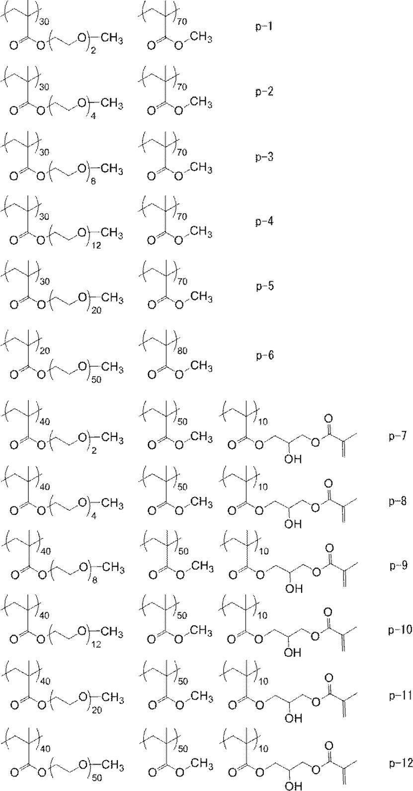
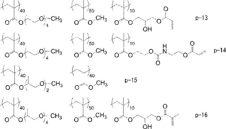
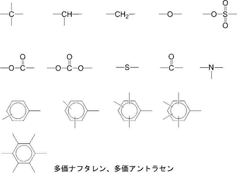
脂肪族チオールのチオール残基は3官能性以上のアルコールと炭素数2~6のメルカプトアルカン酸とから形成されるエステルの残基であることが好ましい。 Trifunctional or higher thiol residues are derived from aromatic or aliphatic thiols. Examples of aromatic thiols include benzene-1,3,5-trithiol, 3,4,8,9-tetramercaptotetrathiafulvalene and 7-methyltrithiouric acid.
The thiol residue of the aliphatic thiol is preferably an ester residue formed from a trifunctional or higher alcohol and a mercaptoalkanoic acid having 2 to 6 carbon atoms.
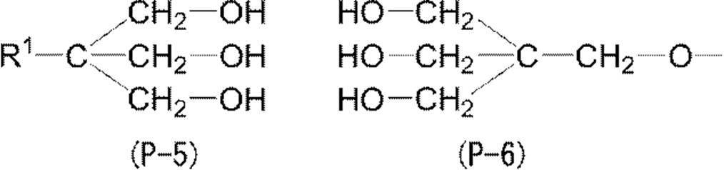
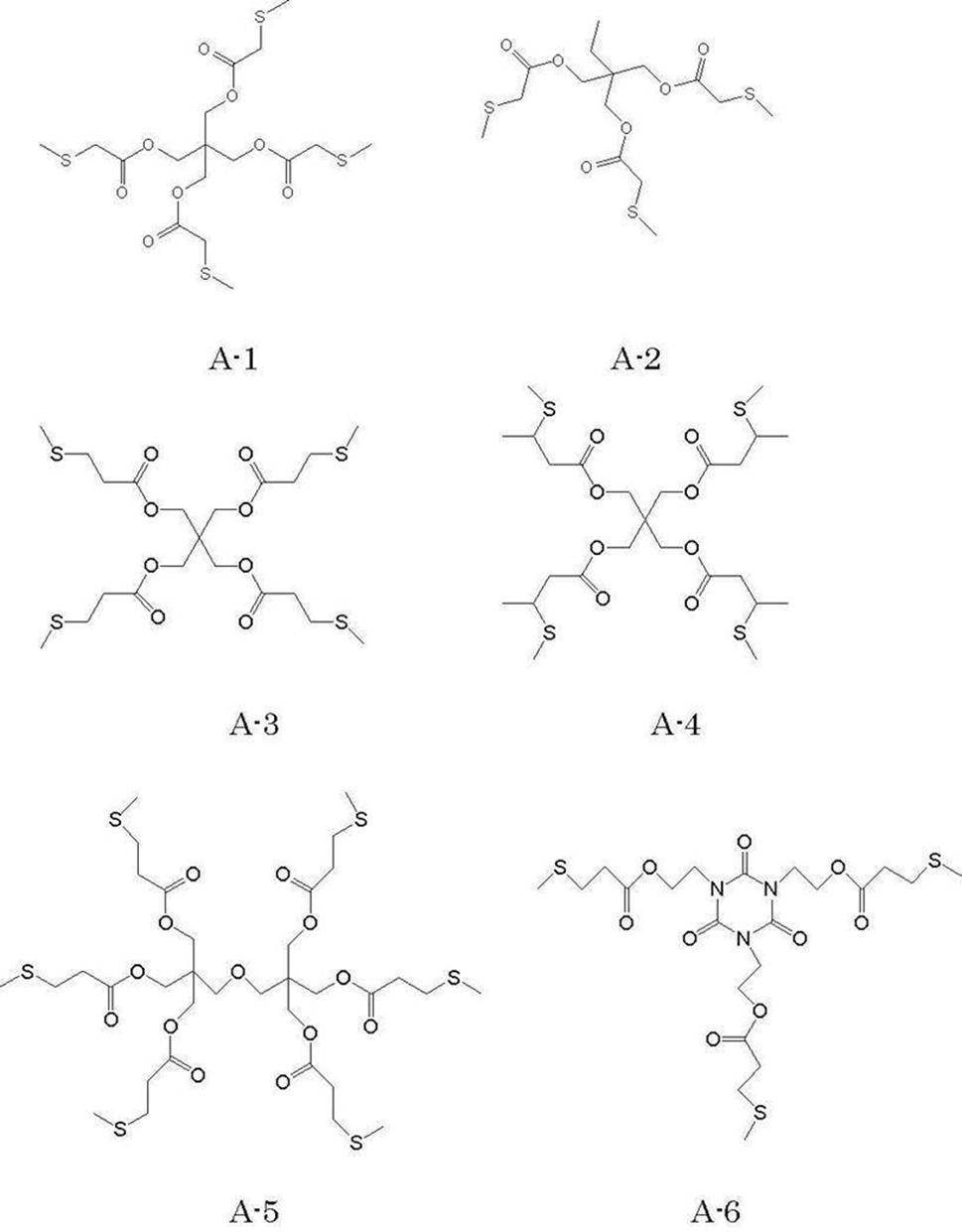

星型ポリマーの具体例を、分岐単位と先端に結合するポリマー鎖の種類とにより、重量平均分子量と共に下記表1に示す。但し、本発明に使用しうる星型ポリマーはこれらに限定されるわけではない。 The weight average molecular weight (Mw) of the star polymer is preferably 5,000 to 500,000, and more preferably 10,000 to 250,000.
Specific examples of the star polymer are shown in Table 1 below together with the weight average molecular weight depending on the branch unit and the type of polymer chain bonded to the tip. However, the star polymer that can be used in the present invention is not limited thereto.

星型ポリマーは、前記の多官能チオール化合物の存在下で、ポリマー鎖を構成する前記モノマーをラジカル重合するなど、公知の方法によって合成可能である。 One type of star polymer may be included in the image recording layer, or two or more types may be included in the image recording layer. The content of the star polymer in the image recording layer is preferably in the range of 0.5% by mass to 90% by mass with respect to the total solid content of the image recording layer, and in the range of 1% by mass to 80% by mass. More preferably, it is more preferably in the range of 1.5 mass% to 70 mass%.
The star polymer can be synthesized by a known method such as radical polymerization of the monomer constituting the polymer chain in the presence of the polyfunctional thiol compound.
画像記録層は、現像性を向上させるため、ポリマー微粒子を含んでもよい。特に、ポリアルキレンオキシド構造を有するポリマー微粒子が好ましい。なかでも側鎖にポリアルキレンオキシド基を有するポリマー微粒子が好ましい。
画像記録層がポリアルキレンオキシド構造を有するポリマー微粒子を含有すると、湿し水の浸透性が向上し、現像性が良好となる。ポリアルキレンオキシド構造としては、炭素数2又は3のアルキレンオキシド単位を2~120個有するアルキレンオキシド構造が好ましく、エチレンオキシド単位を2~120個有するポリエチレンオキシド構造がより好ましい。特にエチレンオキシド単位を20~100個有するポリエチレンオキシド構造が好ましい。このようなポリアルキレンオキシド構造を有するポリマー微粒子によって、耐刷性と現像性を両立することができる。また、着肉性を向上させることができる。 [(G) Polymer fine particles]
The image recording layer may contain fine polymer particles in order to improve developability. In particular, polymer fine particles having a polyalkylene oxide structure are preferred. Of these, polymer fine particles having a polyalkylene oxide group in the side chain are preferred.
When the image recording layer contains polymer fine particles having a polyalkylene oxide structure, the permeability of the fountain solution is improved and the developability is improved. The polyalkylene oxide structure is preferably an alkylene oxide structure having 2 to 120 alkylene oxide units having 2 or 3 carbon atoms, and more preferably a polyethylene oxide structure having 2 to 120 ethylene oxide units. In particular, a polyethylene oxide structure having 20 to 100 ethylene oxide units is preferred. The fine polymer particles having such a polyalkylene oxide structure can achieve both printing durability and developability. Moreover, the inking property can be improved.
ポリマー微粒子を構成するポリマーの具体例としては、エチレン、スチレン、塩化ビニル、アクリル酸メチル、アクリル酸エチル、メタクリル酸メチル、メタクリル酸エチル、塩化ビニリデン、アクリロニトリル、ビニルカルバゾール、ポリアルキレン構造を有するアクリレート又はメタクリレートなどのモノマーのホモポリマーもしくはコポリマー又はそれらの混合物を挙げることができる。その中で、より好適なものとして、ポリスチレン、スチレン及びアクリロニトリルを含む共重合体、ポリメタクリル酸メチルを挙げることができる。 Hydrophobic thermoplastic polymer fine particles include Research Disclosure No. 1 of January 1992. 331,003, JP-A-9-123387, JP-A-9-131850, JP-A-9-171249, JP-A-9-171250, and European Patent No. 931647 are suitable. Can be cited as
Specific examples of the polymer constituting the polymer fine particle include ethylene, styrene, vinyl chloride, methyl acrylate, ethyl acrylate, methyl methacrylate, ethyl methacrylate, vinylidene chloride, acrylonitrile, vinyl carbazole, acrylate having a polyalkylene structure, or Mention may be made of homopolymers or copolymers of monomers such as methacrylates or mixtures thereof. Among them, more preferable examples include a copolymer containing polystyrene, styrene and acrylonitrile, and polymethyl methacrylate.
ポリマー微粒子の含有量は、画像記録層全固形分の5質量%~90質量%の範囲であることが好ましい。 The average particle size of the microcapsules or microgel is preferably 0.01 μm to 3.0 μm. 0.05 μm to 2.0 μm is more preferable, and 0.10 μm to 1.0 μm is particularly preferable. Within this range, good resolution and stability over time can be obtained.
The content of the polymer fine particles is preferably in the range of 5 mass% to 90 mass% of the total solid content of the image recording layer.
画像記録層は、必要に応じて、更に下記の成分を含有することができる。 [Other ingredients]
The image recording layer can further contain the following components as required.
画像記録層は、耐刷性を低下させることなく機上現像性を向上させるために、低分子親水性化合物を含有してもよい。
低分子親水性化合物としては、例えば、水溶性有機化合物としては、エチレングリコール、ジエチレングリコール、トリエチレングリコール、プロピレングリコール、ジプロピレングリコール、トリプロピレングリコール等のグリコール類及びそのエーテル又はエステル誘導体類、グリセリン、ペンタエリスリトール、トリス(2-ヒドロキシエチル)イソシアヌレート等のポリオール類、トリエタノールアミン、ジエタノールアミン、モノエタノールアミン等の有機アミン類及びその塩、アルキルスルホン酸、トルエンスルホン酸、ベンゼンスルホン酸等の有機スルホン酸類及びその塩、アルキルスルファミン酸等の有機スルファミン酸類及びその塩、アルキル硫酸、アルキルエーテル硫酸等の有機硫酸類及びその塩、フェニルホスホン酸等の有機ホスホン酸類及びその塩、酒石酸、シュウ酸、クエン酸、リンゴ酸、乳酸、グルコン酸、アミノ酸類等の有機カルボン酸類及びその塩、ベタイン類、等が挙げられる。 (1) Low molecular weight hydrophilic compound The image recording layer may contain a low molecular weight hydrophilic compound in order to improve the on-press developability without reducing the printing durability.
As the low molecular weight hydrophilic compound, for example, as the water-soluble organic compound, ethylene glycol, diethylene glycol, triethylene glycol, propylene glycol, dipropylene glycol, tripropylene glycol and the like glycols and ether or ester derivatives thereof, glycerin, Polyols such as pentaerythritol and tris (2-hydroxyethyl) isocyanurate, organic amines such as triethanolamine, diethanolamine and monoethanolamine and salts thereof, organic sulfones such as alkylsulfonic acid, toluenesulfonic acid and benzenesulfonic acid Acids and salts thereof, organic sulfamic acids such as alkylsulfamic acid and salts thereof, organic sulfuric acids such as alkylsulfuric acid and alkylethersulfuric acid and salts thereof, phenylphosphonic acid Organic phosphonic acids and salts thereof, tartaric acid, oxalic acid, citric acid, malic acid, lactic acid, gluconic acid, organic carboxylic acids and salts thereof such as amino acids, betaines, and the like.
これらの化合物は1つのみが含まれてもよく、2つ以上の組み合わせが含まれてもよい。 The content of these low molecular weight hydrophilic compounds in the image recording layer is preferably 0.5% by mass or more and 20% by mass or less of the total solid content of the image recording layer. More preferably, they are 1 mass% or more and 15 mass% or less, More preferably, they are 2 mass% or more and 10 mass% or less. In this range, good on-press developability and printing durability can be obtained.
Only one of these compounds may be included, or two or more combinations may be included.
画像記録層は、着肉性を向上させるために、画像記録層にホスホニウム化合物、含窒素低分子化合物、アンモニウム基含有ポリマーなどの感脂化剤を含んでもよい。特に、保護層が無機質の層状化合物を含有する場合、感脂化剤は、表面被覆剤として機能し、無機質の層状化合物による印刷途中の着肉性低下を防止する。 (2) Grease-sensitizing agent The image-recording layer may contain a fat-sensitizing agent such as a phosphonium compound, a nitrogen-containing low molecular weight compound, or an ammonium group-containing polymer in the image-recording layer in order to improve the inking property. In particular, when the protective layer contains an inorganic stratiform compound, the sensitizer functions as a surface coating agent and prevents a decrease in the inking property during printing by the inorganic stratiform compound.
画像記録層は、更にその他の成分として、界面活性剤、着色剤、焼き出し剤、重合禁止剤、紫外線吸収剤、高級脂肪酸誘導体、可塑剤、無機微粒子、無機質層状化合物、及び増感助剤若しくは連鎖移動剤などを含有してもよい。具体的には、特開2008-284817号公報の段落番号[0114]~[0159]、特開2006-091479号公報の段落番号[0023]~[0027]、米国特許公開2008/0311520号明細書の段落番号[0060]に記載の化合物及び添加量が好ましい。 (3) Others The image recording layer further comprises other components such as a surfactant, a colorant, a printout agent, a polymerization inhibitor, an ultraviolet absorber, a higher fatty acid derivative, a plasticizer, inorganic fine particles, an inorganic layered compound, and an increase. You may contain a sensitization agent or a chain transfer agent. Specifically, paragraph numbers [0114] to [0159] of Japanese Patent Application Laid-Open No. 2008-284817, paragraph numbers [0023] to [0027] of Japanese Patent Application Laid-Open No. 2006-091479, and US Patent Publication No. 2008/0311520. The compound and the addition amount described in paragraph [0060] of FIG.
画像記録層は、例えば、特開2008-195018号公報の段落番号[0142]~[0143]に記載のように、必要な上記各成分を公知の溶剤に分散又は溶解して塗布液を調製し、これを支持体上にバーコーター塗布など公知の方法で塗布し、乾燥することで形成される。塗布、乾燥後に得られる支持体上の画像記録層塗布量(固形分)は、用途によって異なるが、一般的に0.3g/m2~3.0g/m2が好ましい。この範囲で、良好な感度と画像記録層の良好な皮膜特性が得られる。 (Formation of image recording layer)
For example, as described in paragraph numbers [0142] to [0143] of JP-A-2008-195018, the image recording layer is prepared by dispersing or dissolving the necessary components described above in a known solvent. It is formed by coating this on a support by a known method such as bar coater coating and drying. The image recording layer coating amount (solid content) on the support obtained after coating and drying varies depending on the use, but is generally preferably 0.3 g / m 2 to 3.0 g / m 2 . Within this range, good sensitivity and good film characteristics of the image recording layer can be obtained.
平版印刷版原版は、画像記録層と支持体との間に下塗り層(中間層と呼ばれることもある)を有することが好ましい。下塗り層は、露光部においては支持体と画像記録層との密着を強化し、未露光部においては画像記録層の支持体からの剥離を生じやすくさせるため、耐刷性を損なわず現像性を向上させるのに寄与する。また、平版印刷版原版が赤外線レーザー露光に供される場合は、下塗り層が断熱層として機能することにより、露光により発生した熱が支持体に拡散して感度が低下するのを防ぐ。 [Undercoat layer]
The lithographic printing plate precursor preferably has an undercoat layer (sometimes referred to as an intermediate layer) between the image recording layer and the support. The undercoat layer enhances the adhesion between the support and the image recording layer in the exposed area, and easily peels off the image recording layer from the support in the unexposed area. Contributes to improvement. When the lithographic printing plate precursor is subjected to infrared laser exposure, the undercoat layer functions as a heat insulating layer, thereby preventing the heat generated by the exposure from diffusing to the support and lowering the sensitivity.
具体的には、特開平10-282679号公報に記載されている付加重合可能なエチレン性二重結合反応基を有しているシランカップリング剤、特開平2-304441号公報記載のエチレン性二重結合反応基を有しているリン化合物が好適に挙げられる。特開2005-238816号、特開2005-125749号、特開2006-239867号、特開2006-215263号の各公報記載の、架橋性基(好ましくは、エチレン性不飽和結合基)、支持体表面に相互作用する官能基、及び/又は親水性基を有する、低分子化合物又は高分子化合物を含有するものも好ましい。より好ましいものとして、特開2005-125749号及び特開2006-188038号公報に記載の支持体表面に吸着可能な吸着性基、親水性基、及び架橋性基を有する高分子ポリマーが挙げられる。 When the compound used for the undercoat layer is a polymer, the polymer is preferably a copolymer of a monomer having an adsorptive group, a monomer having a hydrophilic group, and a monomer having a crosslinkable group. . Examples of the adsorptive group that can be adsorbed on the support surface include a phenolic hydroxy group, a carboxy group, —PO 3 H 2 , —OPO 3 H 2 , —CONHSO 2 —, —SO 2 NHSO 2 —, —COCH 2 COCH 3 Is preferred. As the hydrophilic group, a sulfo group is preferable. The crosslinkable group is preferably a methacryl group or an allyl group. This polymer may have a crosslinkable group introduced by salt formation between the polar substituent of the polymer, a substituent having a counter charge and a compound having an ethylenically unsaturated bond, Other monomers, preferably hydrophilic monomers, may be further copolymerized.
Specifically, a silane coupling agent having an ethylenic double bond reactive group capable of addition polymerization described in JP-A No. 10-282679 and an ethylenic compound described in JP-A No. 2-304441. The phosphorus compound which has a heavy bond reactive group is mentioned suitably. Crosslinkable group (preferably ethylenically unsaturated bond group), support described in JP-A-2005-238816, JP-A-2005-125649, JP-A-2006-239867, JP-A-2006-215263 Those containing a low molecular compound or a high molecular compound having a functional group interacting with the surface and / or a hydrophilic group are also preferable. More preferred are polymer polymers having adsorbable groups, hydrophilic groups, and crosslinkable groups that can be adsorbed on the support surface described in JP-A Nos. 2005-125749 and 2006-188038.
下塗り層用の高分子ポリマーは、質量平均モル質量が5000以上であるのが好ましく、1万~30万であるのがより好ましい。 The content of unsaturated double bonds in the polymer for the undercoat layer is preferably 0.1 mmol to 10.0 mmol, more preferably 0.2 mmol to 5.5 mmol per 1 g of the polymer.
The polymer for the undercoat layer preferably has a mass average molar mass of 5000 or more, more preferably 10,000 to 300,000.
感光性平版印刷版原版に用いられる支持体としては、公知の支持体が用いられる。なかでも、公知の方法で粗面化処理され、陽極酸化処理されたアルミニウム板が好ましい。
アルミニウム板は必要に応じて、特開2001-253181号公報又は特開2001-322365号公報に記載されているような陽極酸化皮膜のマイクロポアの拡大処理又は封孔処理、及び/又は米国特許第2,714,066号、同第3,181,461号、同第3,280,734号及び同第3,902,734号の各明細書に記載されているようなアルカリ金属シリケートあるいは米国特許第3,276,868号、同第4,153,461号及び同第4,689,272号の各明細書に記載されているようなポリビニルホスホン酸などによる表面親水化処理に供されていてもよい。
支持体は、中心線平均粗さが0.10μm~1.2μmであるのが好ましい。 [Support]
As a support used for the photosensitive lithographic printing plate precursor, a known support is used. Of these, an aluminum plate that has been roughened and anodized by a known method is preferred.
If necessary, the aluminum plate may be subjected to a micropore expansion treatment or sealing treatment of an anodized film as described in JP-A No. 2001-253181 or JP-A No. 2001-322365, and / or US Pat. Alkali metal silicates or US patents as described in US Pat. Nos. 2,714,066, 3,181,461, 3,280,734 and 3,902,734 No. 3,276,868, No. 4,153,461 and No. 4,689,272, which have been subjected to surface hydrophilization treatment with polyvinylphosphonic acid or the like as described in each specification. Also good.
The support preferably has a center line average roughness of 0.10 μm to 1.2 μm.
平版印刷版原版は、画像記録層の上に保護層(オーバーコート層)を有することが好ましい。保護層は酸素遮断によって画像形成阻害反応を抑制する機能の他、画像記録層における傷の発生防止、及び高照度レーザー露光時のアブレーション防止の機能を有する。 [Protective layer]
The lithographic printing plate precursor preferably has a protective layer (overcoat layer) on the image recording layer. In addition to the function of suppressing the image formation inhibition reaction by blocking oxygen, the protective layer has a function of preventing scratches in the image recording layer and preventing ablation during high-illuminance laser exposure.
変性ポリビニルアルコールとしては、カルボキシ基又はスルホ基を有する酸変性ポリビニルアルコールが好ましく用いられる。具体的には、特開2005-250216号、特開2006-259137号の公報に記載の変性ポリビニルアルコールが好適である。
保護層は、特開2012-73597号公報に記載されている下記一般式(1)で表される繰り返し単位と一般式(2)で表される繰り返し単位を有する親水性ポリマー(以下、特定親水性ポリマーとも称する)を含有していることが特に好ましい。 Details of the protective layer having such characteristics are described in, for example, US Pat. No. 3,458,311 and JP-B-55-49729. As the low oxygen permeability polymer used for the protective layer, either a water-soluble polymer or a water-insoluble polymer can be appropriately selected and used, and two or more types can be mixed and used as necessary. it can. Specific examples include polyvinyl alcohol, modified polyvinyl alcohol, polyvinyl pyrrolidone, water-soluble cellulose derivatives, poly (meth) acrylonitrile, and the like.
As the modified polyvinyl alcohol, acid-modified polyvinyl alcohol having a carboxy group or a sulfo group is preferably used. Specifically, modified polyvinyl alcohols described in JP-A-2005-250216 and JP-A-2006-259137 are suitable.
The protective layer is a hydrophilic polymer having a repeating unit represented by the following general formula (1) and a repeating unit represented by the general formula (2) described in JP 2012-73597 A (hereinafter referred to as a specific hydrophilic group). It is particularly preferable that the polymer contains a polymer.

なお、置換アルキル基に導入可能な置換基としては、芳香族環基、複素環基及びポリエーテル基などが挙げられる。 In General Formula (1) and General Formula (2), R 1 and R 4 each independently represent a hydrogen atom or a methyl group. R 2 and R 3 each independently represents a hydrogen atom, a methyl group, or an ethyl group. R 5 represents a linear, branched or cyclic unsubstituted alkyl group having 2 to 8 carbon atoms, a substituted alkyl group which may have an aromatic ring or a heterocyclic ring as a substituent, or a group represented by the following general formula (3): Represents a substituent.
Examples of the substituent that can be introduced into the substituted alkyl group include an aromatic ring group, a heterocyclic group, and a polyether group.
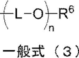
一般式(1)で表わされる繰り返し単位のR2とR3は共に水素原子であることが好ましい。一般式(2)で表わされる繰り返し単位のR5は炭素原子数2~8の直鎖、分岐若しくは環状の無置換アルキル基であることが好ましい。
一般式(1)及び一般式(2)の各式で表わされる繰り返し単位の組み合わせとしては、一般式(1)及び一般式(2)のR1とR4がそれぞれ水素原子であり、一般式(1)のR2とR3がそれぞれ水素原子であり、一般式(2)のR5が炭素原子数4の分岐かつ無置換アルキル基である組み合わせが最も好ましい。 In the general formula (3), L represents an alkylene group having 2 to 6 carbon atoms, and R 6 represents a linear, branched or cyclic unsubstituted alkyl group or aromatic substituted alkyl group having 4 to 8 carbon atoms. . n is the average number of moles of polyether added and represents a number of 2 to 4.
It is preferable that R 2 and R 3 of the repeating unit represented by the general formula (1) are both hydrogen atoms. R 5 of the repeating unit represented by the general formula (2) is preferably a linear, branched or cyclic unsubstituted alkyl group having 2 to 8 carbon atoms.
As a combination of repeating units represented by the formulas (1) and (2), R 1 and R 4 in the formula (1) and formula (2) are each a hydrogen atom, A combination in which R 2 and R 3 in (1) are each a hydrogen atom, and R 5 in general formula (2) is a branched and unsubstituted alkyl group having 4 carbon atoms is most preferable.
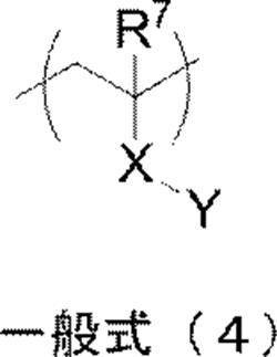
一般式(4)で表される繰り返し単位は、水溶性及び機上現像性の観点から、Yがスルホン酸基、スルホン酸塩基、カルボキシベタイン基、スルホベタイン基、又はアンモニウム基であることが好ましく、スルホン酸基、スルホン酸塩基又はスルホベタイン基であることがより好ましい。
Xは下記構造群(5)に示す構造から選ばれる二価の連結鎖であるか、又は、下記構造群(6)に示す構造から選ばれる複数を組み合わせてなる二価の連結基であることが好ましい。 In general formula (4), R 7 represents a hydrogen atom or a methyl group. X represents a single bond, a divalent linking group selected from the structures shown in the following structural group (5), or a divalent linking group formed by combining a plurality selected from the structures shown in the following structural group (6). Y is a carboxylic acid group, a carboxylic acid group, a sulfonic acid group, a sulfonic acid group, a phosphoric acid group, a phosphoric acid group, a phosphonic acid group, a phosphonic acid group, a hydroxyl group, a carboxybetaine group, a sulfobetaine group, an ammonium group, or Represents a polyether group represented by the following general formula (7).
In the repeating unit represented by the general formula (4), Y is preferably a sulfonic acid group, a sulfonic acid group, a carboxybetaine group, a sulfobetaine group, or an ammonium group from the viewpoint of water solubility and on-press developability. More preferably a sulfonic acid group, a sulfonic acid group or a sulfobetaine group.
X is a divalent linking chain selected from the structures shown in the following structural group (5), or a divalent linking group formed by combining a plurality selected from the structures shown in the following structural group (6). Is preferred.

また、 In the general formula (7), L ′ represents an alkylene group having 2 to 3 carbon atoms, and R 8 represents a hydrogen atom or a methyl group. n ′ is an average added mole number of the polyether and is a number of 2 to 4.
Also,
保護層に用いられる特定親水性ポリマーが一般式(4)で表される繰り返し単位を上記好ましい範囲で含有すると、感光性平版印刷版原版は、良好な機上現像性、着肉性及び耐刷性を得られる。 The specific hydrophilic polymer preferably contains 0.3 mol% to 5 mol% of the repeating unit represented by the general formula (4), more preferably contains 0.3 mol% to 3 mol%. Those containing 3 mol% to 1.5 mol% are more preferable.
When the specific hydrophilic polymer used in the protective layer contains the repeating unit represented by the general formula (4) in the above-mentioned preferable range, the photosensitive lithographic printing plate precursor has good on-press developability, inking property and printing durability. You can get sex.


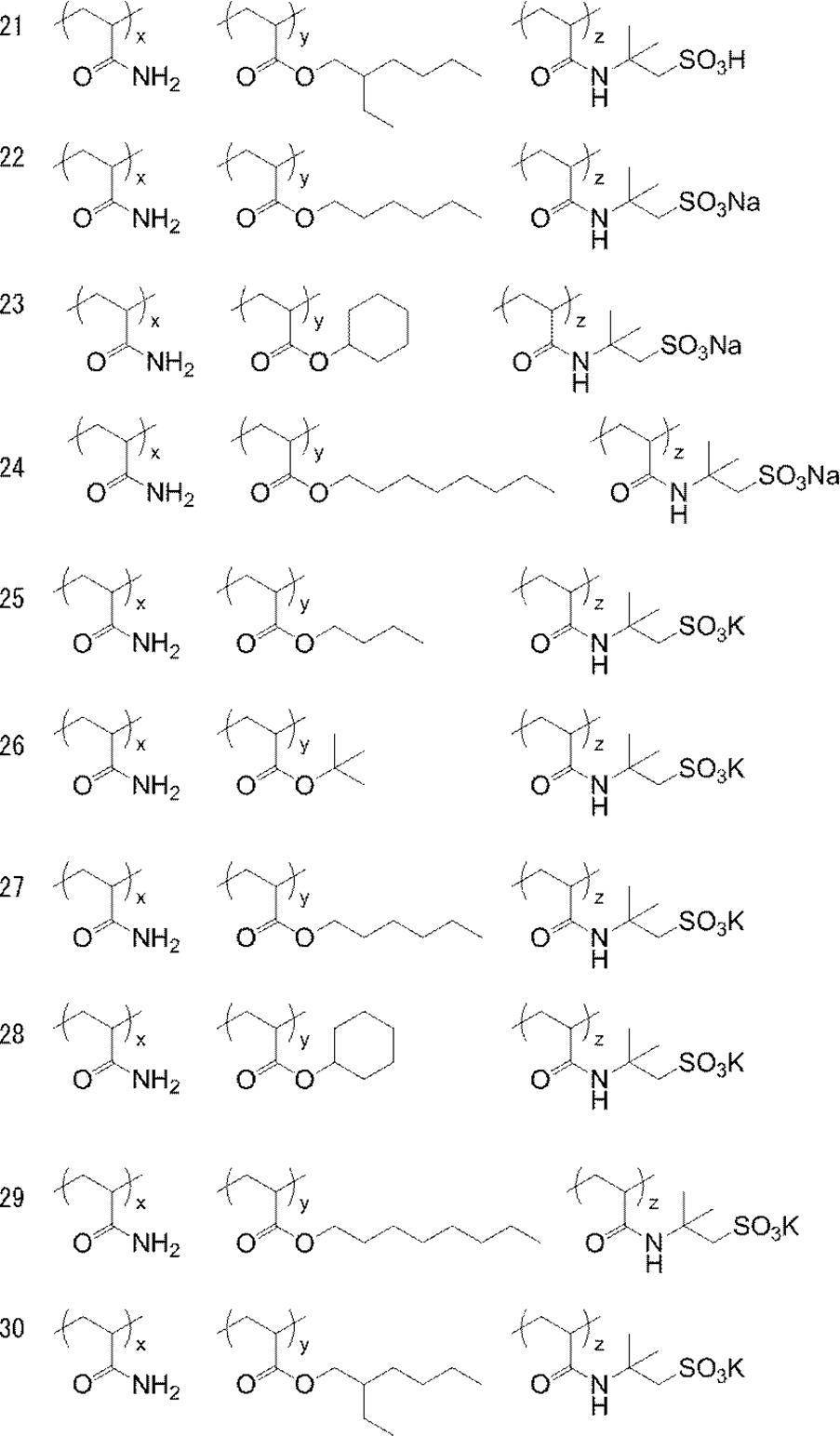
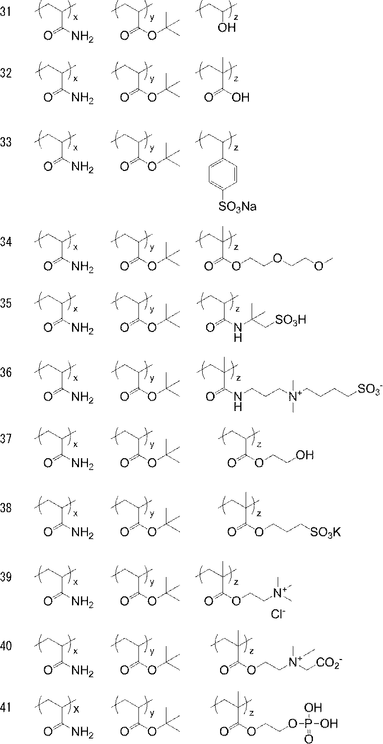
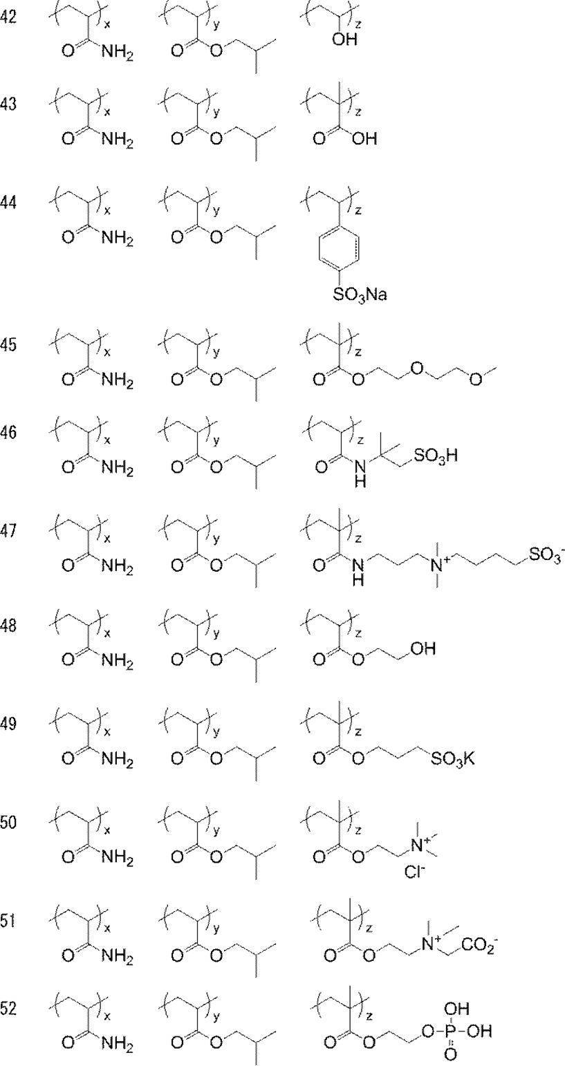
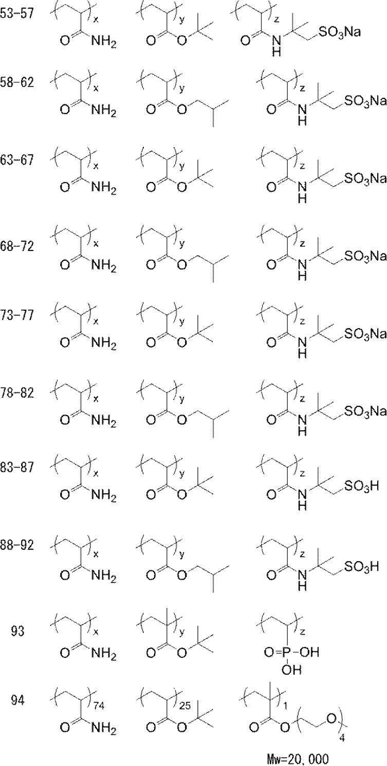
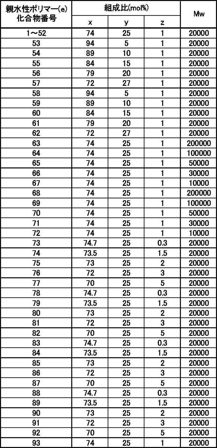
保護層は、可撓性付与のための可塑剤、塗布性を向上させるための界面活性剤、表面の滑り性を制御する無機微粒子、及び/又は紫外線吸収剤など公知の添加物を含むことができる。また、画像記録層の説明に記載した感脂化剤を保護層に含有させることもできる。 The protective layer preferably contains an inorganic layered compound such as natural mica and synthetic mica as described in JP-A-2005-119273 in order to enhance oxygen barrier properties.
The protective layer may contain a known additive such as a plasticizer for imparting flexibility, a surfactant for improving coatability, inorganic fine particles for controlling surface slipperiness, and / or an ultraviolet absorber. it can. Further, the protective layer can contain the sensitizer described in the description of the image recording layer.
このようにして、本発明の廃液濃縮方法及び本発明のリサイクル方法に係る現像処理工程に適用される感光性平版印刷版原版が得られる。 As for the method of applying such a protective layer, it is applied by a known method described in, for example, US Pat. No. 3,458,311 and JP-A-55-49729. The coating amount of the protective layer is, the coating amount after drying is preferably in the range of 0.01g / m 2 ~ 10g / m 2, more preferably in the range of 0.02g / m 2 ~ 3g / m 2, Most preferably, it is in the range of 0.02 g / m 2 to 1 g / m 2 .
In this way, a photosensitive lithographic printing plate precursor applied to the development processing step according to the waste liquid concentration method of the present invention and the recycling method of the present invention is obtained.
感光性平版印刷版原版を、画像様露光して、現像処理を行うことで平版印刷版が作製される。なお、本発明の廃液濃縮方法及び本発明のリサイクル方法に係る製版処理において、平版印刷版原版が自動現像機の現像処理浴で現像液により現像処理され、その後、水洗処理及び不感脂化処理に順次供されることは既述の通りである。 [Plate making method]
The photosensitive lithographic printing plate precursor is imagewise exposed and developed to produce a lithographic printing plate. In the plate making treatment according to the waste liquid concentration method of the present invention and the recycling method of the present invention, the lithographic printing plate precursor is developed with a developer in a development treatment bath of an automatic processor, and then subjected to a water washing treatment and a desensitizing treatment. As described above, it is provided sequentially.
平版印刷版原版は、線画像、網点画像等を有する透明原画を通してレーザー露光するかデジタルデータによるレーザー光走査等で画像様に露光される。
露光に用いる光源の波長は300nm~450nm又は750nm~1400nmが好ましい。光源の波長が300nm~450nmの場合は、極大吸収波長がこの領域にある増感色素を画像記録層に有する平版印刷版原版が用いられ、光源の波長が750nm~1400nmの場合は、この領域に吸収を有する増感色素である赤外線吸収剤を画像記録層に含有する平版印刷版原版が用いられる。300nm~450nm波長光の光源としては、半導体レーザーが好適である。750nm~1400nm波長光の光源としては、赤外線を放射する固体レーザー及び半導体レーザーが好適である。露光機構は、内面ドラム方式、外面ドラム方式、フラットベッド方式等の何れでもよい。 [Image-like exposure process]
The lithographic printing plate precursor is imagewise exposed by laser exposure through a transparent original image having a line image, a halftone dot image or the like, or by laser beam scanning by digital data.
The wavelength of the light source used for exposure is preferably 300 nm to 450 nm or 750 nm to 1400 nm. When the wavelength of the light source is 300 nm to 450 nm, a lithographic printing plate precursor having a sensitizing dye having a maximum absorption wavelength in this region in the image recording layer is used. When the wavelength of the light source is 750 nm to 1400 nm, this region is used. A lithographic printing plate precursor containing an infrared absorbing agent which is a sensitizing dye having absorption in an image recording layer is used. A semiconductor laser is suitable as a light source for light having a wavelength of 300 nm to 450 nm. As a light source for light having a wavelength of 750 nm to 1400 nm, a solid-state laser and a semiconductor laser that emit infrared light are suitable. The exposure mechanism may be any of an internal drum system, an external drum system, a flat bed system, and the like.
上記の現像液は、露光された平版印刷版原版の現像液及び現像補充液として用いることができ、既述のように自動処理機の現像浴に適用することが好ましい。
自動処理機を用いて現像する場合、処理量に応じて現像液が疲労してくるので、補充液又は新鮮な現像液を補充して現像処理能力を回復させてもよい。本発明のリサイクル方法においてもこの補充方式が好ましく適用される。 [Development processing method]
The developer described above can be used as a developer and a development replenisher for the exposed lithographic printing plate precursor, and is preferably applied to a developer bath of an automatic processor as described above.
When developing using an automatic processor, the developing solution becomes fatigued according to the amount of processing, and therefore the replenishing solution or fresh developing solution may be supplemented to restore the developing processing capability. This replenishment method is also preferably applied to the recycling method of the present invention.
平版印刷版原版から平版印刷版を作製する製版プロセスにおいては、必要に応じ、露光前、露光中、又は露光から現像までの間に、全面を加熱してもよい。このような加熱により、画像記録層中の画像形成反応が促進され、感度や耐刷性の向上や感度の安定化といった利点が生じ得る。さらに、画像強度及び耐刷性の向上を目的として、現像後の画像に対し、全面後加熱もしくは全面露光を行うことも有効である。通常、現像前の加熱は150℃以下の穏和な条件で行う事が好ましい。前加熱の温度が高すぎると、非画像部にかぶりが生じる等の問題を生じる。現像後の加熱処理には非常に強い条件を利用する。通常は200℃~500℃の範囲である。後加熱処理の温度が低すぎると十分な画像強化作用が得られず、高すぎる場合には支持体の劣化、画像部の熱分解が生じる。 [Other plate making processes]
In the plate making process for producing a lithographic printing plate from a lithographic printing plate precursor, the entire surface may be heated before exposure, during exposure, or between exposure and development, if necessary. Such heating promotes an image forming reaction in the image recording layer, and may have advantages such as improvement in sensitivity and printing durability and stabilization of sensitivity. Further, for the purpose of improving the image strength and printing durability, it is also effective to subject the developed image to full post heating or full exposure. Usually, heating before development is preferably performed under a mild condition of 150 ° C. or less. If the preheating temperature is too high, problems such as fogging in the non-image area occur. Very strong conditions are used for the heat treatment after development. Usually, it is in the range of 200 ° C to 500 ° C. If the temperature of the post-heating treatment is too low, sufficient image strengthening action cannot be obtained, and if it is too high, the support is deteriorated and the image portion is thermally decomposed.
〔I〕平版印刷版原版(1)の作製 [Examples 1 to 9, Comparative Examples 1 to 7]
[I] Preparation of planographic printing plate precursor (1)
厚み0.3mmのアルミニウム板(Al含有量が99.5質量%以上である材質JIS A 1050)の表面の圧延油を除去するため、10質量%アルミン酸ソーダ水溶液を用いて50℃で30秒間、脱脂処理を施した。その後、径0.3mmのナイロン毛が束植されたブラシ3本とメジアン径25μmのパミス-水懸濁液(比重1.1g/cm3)を用いアルミニウム板表面を砂目立てして、水でよく洗浄した。この板を45℃の25質量%水酸化ナトリウム水溶液に9秒間浸漬してエッチングを行い、水洗後、更に60℃で20質量%硝酸に20秒間浸漬し、水洗した。この時の砂目立て表面のエッチング量は約3g/m2であった。 (1) Production of support In order to remove rolling oil on the surface of a 0.3 mm thick aluminum plate (material JIS A 1050 having an Al content of 99.5% by mass or more), a 10% by mass sodium aluminate aqueous solution was used. A degreasing treatment was performed at 50 ° C. for 30 seconds. Thereafter, the surface of the aluminum plate was grained using three brushes in which nylon hairs having a diameter of 0.3 mm were bundled and a pumice-water suspension (specific gravity 1.1 g / cm 3 ) having a median diameter of 25 μm. Washed well. This plate was etched by being immersed in a 25 mass% sodium hydroxide aqueous solution at 45 ° C for 9 seconds, washed with water, further immersed in 20 mass% nitric acid at 60 ° C for 20 seconds, and washed with water. At this time, the etching amount of the grained surface was about 3 g / m 2 .
次に、この板に15質量%硫酸(アルミニウムイオンを0.5質量%含む)を電解液として電流密度15A/dm2で処理することにより2.5g/m2の直流陽極酸化皮膜を設けた後、水洗、乾燥して支持体(1)を作製した。
その後、非画像部の親水性を確保するため、支持体(1)に2.5質量%3号ケイ酸ソーダ水溶液を用いて60℃で10秒間、シリケート処理を施し、その後、水洗して支持体(2)を得た。支持体(2)表面に付着したSiの量は10mg/m2であった。支持体(2)の中心線平均粗さ(Ra)を直径2μmの針を用いて測定したところ、0.51μmであった。 Subsequently, nitric acid electrolysis was performed with an aqueous solution of 0.5% by mass of hydrochloric acid (containing 0.5% by mass of aluminum ions) and an electrolytic solution having a liquid temperature of 50 ° C. under the condition of an electric quantity of 50 C / dm 2 when the aluminum plate was the anode. In the same manner as above, an electrochemical surface roughening treatment was performed, followed by washing with water by spraying.
Next, a direct current anodic oxide film of 2.5 g / m 2 was provided on this plate by treating the plate with 15% by mass sulfuric acid (containing 0.5% by mass of aluminum ions) at an electric current density of 15 A / dm 2 . Then, it washed with water and dried and produced the support body (1).
Thereafter, in order to ensure the hydrophilicity of the non-image area, the support (1) was subjected to a silicate treatment at 60 ° C. for 10 seconds using an aqueous 2.5 mass% No. 3 sodium silicate solution, and then washed with water for support. Body (2) was obtained. The amount of Si attached to the surface of the support (2) was 10 mg / m 2 . The center line average roughness (Ra) of the support (2) was measured using a needle having a diameter of 2 μm and found to be 0.51 μm.
次に、支持体(2)上に、下記組成を有する下塗り層塗布液(1)を乾燥塗布量が20mg/m2になるよう塗布して、以下の実験に用いる下塗り層を有する支持体を作製した。 (2) Formation of undercoat layer Next, an undercoat layer coating solution (1) having the following composition is applied on the support (2) so that the dry coating amount is 20 mg / m 2 and used in the following experiments. A support having an undercoat layer was prepared.
・下記構造の下塗り層用化合物(1) 0.18g
・メタノール 55.24g
・水 6.15g <Composition of undercoat layer coating solution (1)>
-Undercoat layer compound (1) having the following structure: 0.18 g
・ Methanol 55.24g
・ Water 6.15g

前記のようにして形成された下塗り層上に、画像記録層塗布液(C)をバー塗布した後、100℃60秒でオーブン乾燥し、乾燥塗布量1.0g/m2の画像記録層を形成した。 (1) Formation of Image Recording Layer After the image recording layer coating solution (C) is bar coated on the undercoat layer formed as described above, it is oven dried at 100 ° C. for 60 seconds, and the dry coating amount is 1.0 g. An image recording layer of / m 2 was formed.
・バインダーポリマー(1)〔下記構造〕 0.240g
・赤外線吸収剤(1)〔下記構造〕 0.030g
・ラジカル発生剤(1)〔下記構造〕 0.162g
・重合性化合物
トリス(アクリロイルオキシエチル)イソシアヌレート
(NKエステルA-9300、新中村化学(株)製)0.192g
・低分子親水性化合物
トリス(2-ヒドロキシエチル)イソシアヌレート 0.062g
・低分子親水性化合物(1)〔下記構造〕0.050g
・感脂化剤 ホスホニウム化合物(1)〔下記構造〕 0.055g
・感脂化剤
ベンジル-ジメチル-オクチルアンモニウム・PF6塩 0.018g
・感脂化剤 アンモニウム基含有ポリマー
[下記構造、還元比粘度44cSt/g/ml]0.035g
・フッ素系界面活性剤(1)〔下記構造〕 0.008g
・2-ブタノン 1.091g
・1-メトキシ-2-プロパノール 8.609g <Composition of photosensitive solution (1)>
-Binder polymer (1) [the following structure] 0.240 g
Infrared absorber (1) [the following structure] 0.030 g
-Radical generator (1) [the following structure] 0.162 g
Polymerizable compound tris (acryloyloxyethyl) isocyanurate (NK ester A-9300, manufactured by Shin-Nakamura Chemical Co., Ltd.) 0.192 g
・ Low molecular weight hydrophilic compound Tris (2-hydroxyethyl) isocyanurate 0.062g
・ Low molecular weight hydrophilic compound (1) [the following structure] 0.050 g
-Sensitizing agent Phosphonium compound (1) [the following structure] 0.055 g
・ Sensitizer Benzyl-dimethyl-octylammonium ・ PF 6 salt 0.018g
-Sensitizing agent Ammonium group-containing polymer [the following structure, reduced specific viscosity 44 cSt / g / ml] 0.035 g
・ Fluorosurfactant (1) [The following structure] 0.008g
・ 2-butanone 1.091g
・ 1-methoxy-2-propanol 8.609g
・ミクロゲル(1) 2.640g
・蒸留水 2.425g <Composition of microgel solution (1)>
・ Microgel (1) 2.640 g
・ Distilled water 2.425g

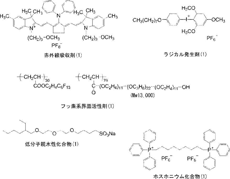
油相成分として、トリメチロールプロパンとキシレンジイソシアナート付加体(商品名:タケネートD-110N、三井武田ケミカル(株)製、75質量%酢酸エチル溶液)10g、アロニックスSR-399(商品名、東亞合成(株)製)6.00g、パイオニンA-41C(商品名、竹本油脂(株)製)0.12gを酢酸エチル16.67gに溶解した。水相成分としてPVA-205(商品名、クラレ社製)の4質量%水溶液37.5gを調製した。油相成分および水相成分を混合し、ホモジナイザーを用いて12000rpmで10分間乳化した。得られた乳化物を、蒸留水25gに添加し、室温で30分攪拌後、40℃で2時間攪拌した。このようにして得られたマイクロカプセル液を、固形分濃度が15質量%になるように蒸留水を用いて希釈し、これをミクロゲル(1)とした。乾式粒度分布測定装置(商品名:LA-910、(株)堀場製作所製)で測定したミクロゲル(1)の平均粒径は0.2μmであった。 -Synthesis of microgel (1)-
As an oil phase component, trimethylolpropane and xylene diisocyanate adduct (trade name: Takenate D-110N, manufactured by Mitsui Takeda Chemical Co., Ltd., 75 mass% ethyl acetate solution), 10 g, Aronix SR-399 (trade name, Tojo) Synthetic Co., Ltd. (6.00 g) and Pionein A-41C (trade name, Takemoto Yushi Co., Ltd.) 0.12 g were dissolved in ethyl acetate 16.67 g. As an aqueous phase component, 37.5 g of a 4 mass% aqueous solution of PVA-205 (trade name, manufactured by Kuraray Co., Ltd.) was prepared. The oil phase component and the aqueous phase component were mixed and emulsified for 10 minutes at 12000 rpm using a homogenizer. The obtained emulsion was added to 25 g of distilled water, stirred at room temperature for 30 minutes, and then stirred at 40 ° C. for 2 hours. The microcapsule solution thus obtained was diluted with distilled water so that the solid content concentration was 15% by mass, and this was designated as microgel (1). The average particle size of the microgel (1) measured by a dry particle size distribution analyzer (trade name: LA-910, manufactured by Horiba, Ltd.) was 0.2 μm.
上記画像記録層上に、さらに下記組成の保護層塗布液(1)をバー塗布した後、120℃、60秒でオーブン乾燥し、乾燥塗布量0.15g/m2の保護層を形成して平版印刷版原版(1)を得た。 (2) Formation of Protective Layer After the protective layer coating solution (1) having the following composition was further bar-coated on the image recording layer, it was oven-dried at 120 ° C. for 60 seconds, and the dry coating amount was 0.15 g / m 2. A lithographic printing plate precursor (1) was obtained.
イオン交換水193.6gに合成雲母(商品名:ソマシフME-100、コープケミカル(株)製)6.4gを添加し、ホモジナイザーを用いて平均粒径(レーザー散乱法)が3μmになるまで分散した。得られた分散粒子のアスペクト比は100以上であった。 (Preparation of inorganic layered compound dispersion (1))
6.4 g of synthetic mica (trade name: Somasif ME-100, manufactured by Corp Chemical Co., Ltd.) is added to 193.6 g of ion-exchanged water, and dispersed using an homogenizer until the average particle size (laser scattering method) becomes 3 μm. did. The aspect ratio of the obtained dispersed particles was 100 or more.
・無機質層状化合物分散液(1)(上記で得たもの) 1.5g
・親水性ポリマー(1)(固形分)〔下記構造、Mw:3万〕0.55g
・ポリビニルアルコール(商品名:CKS50、日本合成化学工業(株)製、スルホン酸変性、けん化度99モル%以上、重合度300)6質量%水溶液 0.10g
・ポリビニルアルコール(商品名:PVA-405、(株)クラレ製、けん化度81.5モル%、重合度500)6質量%水溶液 0.03g
・界面活性剤(商品名:エマレックス710、日本エマルジョン(株)製)1質量%水溶液 0.86g
・イオン交換水 6.0g <Composition of coating liquid (1) for protective layer>
・ Inorganic layered compound dispersion (1) (obtained above) 1.5 g
Hydrophilic polymer (1) (solid content) [the following structure, Mw: 30,000] 0.55 g
・ Polyvinyl alcohol (trade name: CKS50, manufactured by Nippon Synthetic Chemical Industry Co., Ltd., sulfonic acid modification, saponification degree 99 mol% or more, polymerization degree 300) 6% by mass aqueous solution 0.10 g
Polyvinyl alcohol (trade name: PVA-405, manufactured by Kuraray Co., Ltd., saponification degree 81.5 mol%, polymerization degree 500) 6% by mass aqueous solution 0.03 g
-Surfactant (trade name: Emalex 710, manufactured by Nippon Emulsion Co., Ltd.) 1% by weight aqueous solution 0.86 g
・ Ion-exchanged water 6.0g

下記組成の現像液(A)~現像液(M)を作製した。
<現像液(A)>
・ノニオン性界面活性剤(ポリオキシエチレンナフタレンエーテル)(商品名:ニューコール B13、日本乳化剤(株)製、固形分100%)5.0質量%
・キレート剤((エチレンジアミンジコハク酸3ナトリウム塩)商品名:キレストEDDS-35、キレスト(株)製)0.5質量%
・シリコーン系消泡剤(商品名:TSA739モメンティブ・パフォーマンス・マテリアルズ・ジャパン合同会社製)0.1質量%
・防腐剤(商品名:Acticide LA1206、ソー・ジャパン(株)製) 0.1質量%
水を加えて全量を100質量%とした。(pH:9.4)
現像液(A)~(C)、(I)~(K)の調製に用いられた界面活性剤であるニューコール B13(商品名、日本乳化剤(株)製)は、一般式(B)に包含されるナフタレン骨格を有するノニオン性界面活性剤である。 [Preparation of developer]
Developers (A) to (M) having the following compositions were prepared.
<Developer (A)>
Nonionic surfactant (polyoxyethylene naphthalene ether) (trade name: New Coal B13, manufactured by Nippon Emulsifier Co., Ltd., solid content 100%) 5.0% by mass
Chelating agent ((ethylenediamine disuccinic acid trisodium salt) trade name: Kirest EDDS-35, manufactured by Kirest Co., Ltd.) 0.5% by mass
・ Silicone-based antifoaming agent (trade name: TSA739 Momentive Performance Materials Japan GK) 0.1% by mass
-Preservative (trade name: Actide LA1206, manufactured by So Japan Co., Ltd.) 0.1% by mass
Water was added to make the total amount 100% by mass. (PH: 9.4)
New Coal B13 (trade name, manufactured by Nippon Emulsifier Co., Ltd.), which is a surfactant used in the preparation of the developers (A) to (C) and (I) to (K), is represented by the general formula (B). It is a nonionic surfactant having an included naphthalene skeleton.
・ノニオン性界面活性剤(ポリオキシエチレンナフタレンエーテル)(商品名:ニューコール B13、日本乳化剤(株)製、固形分100%)5.0質量%
・キレート剤(エチレンジアミンジコハク酸3ナトリウム塩)(商品名:キレストEDDS-35、キレスト(株)製 )0.5質量%
・シリコーン系消泡剤(商品名:TSA739、モメンティブ・パフォーマンス・マテリアルズ・ジャパン合同会社製)0.1質量%
・防腐剤(商品名:Acticide LA1206ソー・ジャパン(株)製) 0.1質量%
水を加えて全量を100質量%とした。
(リン酸を添加し、pHを6.0に調整) <Developer (B)>
Nonionic surfactant (polyoxyethylene naphthalene ether) (trade name: New Coal B13, manufactured by Nippon Emulsifier Co., Ltd., solid content 100%) 5.0% by mass
Chelating agent (ethylenediamine disuccinic acid trisodium salt) (trade name: Kirest EDDS-35, manufactured by Kirest Co., Ltd.) 0.5% by mass
・ Silicone-based antifoaming agent (trade name: TSA739, manufactured by Momentive Performance Materials Japan GK) 0.1% by mass
-Preservative (trade name: manufactured by Actide LA1206 So Japan Co., Ltd.) 0.1% by mass
Water was added to make the total amount 100% by mass.
(Phosphoric acid added to adjust pH to 6.0)
・ノニオン性界面活性剤(ポリオキシエチレンナフタレンエーテル)(商品名:ニューコール B13、日本乳化剤(株)製、固形分100%)5.0質量%
・キレート剤(エチレンジアミンジコハク酸3ナトリウム塩)(商品名:キレストEDDS-35、キレスト(株)製 ) 0.5質量%
・シリコーン系消泡剤(商品名:TSA739、モメンティブ・パフォーマンス・マテリアルズ・ジャパン合同会社製)0.1質量%
・防腐剤(商品名:Acticide LA1206、ソー・ジャパン(株)製) 0.1質量%
水を加えて全量を100質量%とした。
(リン酸を添加し、pHを8.0に調整) <Developer (C)>
Nonionic surfactant (polyoxyethylene naphthalene ether) (trade name: New Coal B13, manufactured by Nippon Emulsifier Co., Ltd., solid content 100%) 5.0% by mass
Chelating agent (ethylenediamine disuccinic acid trisodium salt) (trade name: Kirest EDDS-35, manufactured by Kirest Co., Ltd.) 0.5% by mass
・ Silicone-based antifoaming agent (trade name: TSA739, manufactured by Momentive Performance Materials Japan GK) 0.1% by mass
-Preservative (trade name: Actide LA1206, manufactured by So Japan Co., Ltd.) 0.1% by mass
Water was added to make the total amount 100% by mass.
(Phosphoric acid added to adjust pH to 8.0)
・アニオン性界面活性剤(アルキルナフタレンスルホン酸ナトリウム)(商品名:ペレックス NBL、花王(株)製、35%水溶液) 10.0質量%
・キレート剤(エチレンジアミンジコハク酸3ナトリウム塩)(商品名:キレストEDDS-35、キレスト(株)製)0.5質量%
・シリコーン系消泡剤(商品名:TSA739、モメンティブ・パフォーマンス・マテリアルズ・ジャパン合同会社製)0.1質量%
・防腐剤(商品名:Acticide LA1206、ソー・ジャパン(株)製) 0.1質量%
水を加えて全量を100質量%とした。(pH:8.0)
現像液(D)の調製に用いられた界面活性剤であるペレックス NBL(商品名、花王(株)製)は、一般式(A)に包含されるナフタレン骨格を有するアニオン性界面活性剤である。 <Developer (D)>
Anionic surfactant (sodium alkylnaphthalene sulfonate) (trade name: Perex NBL, manufactured by Kao Corporation, 35% aqueous solution) 10.0% by mass
Chelating agent (ethylenediamine disuccinic acid trisodium salt) (trade name: Kirest EDDS-35, manufactured by Kirest Co., Ltd.) 0.5% by mass
・ Silicone-based antifoaming agent (trade name: TSA739, manufactured by Momentive Performance Materials Japan GK) 0.1% by mass
-Preservative (trade name: Actide LA1206, manufactured by So Japan Co., Ltd.) 0.1% by mass
Water was added to make the total amount 100% by mass. (PH: 8.0)
Perex NBL (trade name, manufactured by Kao Co., Ltd.), which is a surfactant used for preparing the developer (D), is an anionic surfactant having a naphthalene skeleton included in the general formula (A). .
・アニオン性界面活性剤(ポリオキシエチレンアリールエーテル硫酸エステル塩)(商品名:ニューコールB4-SN、日本乳化剤(株)製、60%水溶液)7.0質量%
・キレート剤(エチレンジアミンジコハク酸3ナトリウム塩)(商品名:キレストEDDS-35、キレスト(株)製) 0.5質量%
・シリコーン系消泡剤(商品名:TSA739、モメンティブ・パフォーマンス・マテリアルズ・ジャパン合同会社製)0.05質量%
・防腐剤(商品名:バイオホープ、ケイ・アイ化成(株)製) 0.1質量%
水を加えて全量を100質量%とした。(pH:8.5)
現像液(E)の調製に用いられた界面活性剤であるニューコールB4-SN(商品名、日本乳化剤(株)製)は、一般式(A)に包含されるナフタレン骨格を有するアニオン性界面活性剤である。 <Developer (E)>
Anionic surfactant (polyoxyethylene aryl ether sulfate ester salt) (trade name: New Coal B4-SN, manufactured by Nippon Emulsifier Co., Ltd., 60% aqueous solution) 7.0% by mass
Chelating agent (ethylenediamine disuccinic acid trisodium salt) (trade name: Kirest EDDS-35, manufactured by Kirest Co., Ltd.) 0.5% by mass
・ Silicone-based antifoaming agent (trade name: TSA739, manufactured by Momentive Performance Materials Japan GK) 0.05% by mass
・ Preservative (Brand name: Bio Hope, manufactured by KAI Kasei Co., Ltd.) 0.1% by mass
Water was added to make the total amount 100% by mass. (PH: 8.5)
Neucor B4-SN (trade name, manufactured by Nippon Emulsifier Co., Ltd.), which is a surfactant used for preparing the developer (E), is an anionic interface having a naphthalene skeleton included in the general formula (A). It is an activator.
・アニオン性界面活性剤(ドデシルジフェニルエーテルジスルホン酸ナトリウム)(商品名:エレミノールMON-2、三洋化成工業(株)製、47%水溶液) 10.0質量%
・キレート剤(エチレンジアミンジコハク酸3ナトリウム塩)(商品名:キレストEDDS-35、キレスト(株)製 ) 0.5質量%
・シリコーン系消泡剤(商品名:TSA739、モメンティブ・パフォーマンス・マテリアルズ・ジャパン合同会社製)0.05質量%
・防腐剤(商品名:バイオホープ、ケイ・アイ化成(株)製)0.1質量%
水を加えて全量を100質量%とした。(pH:9.0)
現像液(F)の調製に用いられた界面活性剤であるエレミノールMON-2(商品名、三洋化成工業(株)製)は、分子内にナフタレン骨格を有しない、本発明の範囲外のアニオン性界面活性剤である。 <Comparison developer (F)>
Anionic surfactant (sodium dodecyl diphenyl ether disulfonate) (trade name: Eleminol MON-2, Sanyo Chemical Industries, Ltd., 47% aqueous solution) 10.0% by mass
Chelating agent (ethylenediamine disuccinic acid trisodium salt) (trade name: Kirest EDDS-35, manufactured by Kirest Co., Ltd.) 0.5% by mass
・ Silicone-based antifoaming agent (trade name: TSA739, manufactured by Momentive Performance Materials Japan GK) 0.05% by mass
-Preservative (trade name: Bio Hope, manufactured by KAI Kasei Co., Ltd.) 0.1% by mass
Water was added to make the total amount 100% by mass. (PH: 9.0)
Eleminol MON-2 (trade name, manufactured by Sanyo Kasei Kogyo Co., Ltd.), a surfactant used for the preparation of the developer (F), is an anion outside the scope of the present invention, which does not have a naphthalene skeleton in the molecule. Surfactant.
・ノニオン性界面活性剤(ポリオキシエチレンジスチレン化フェニルエーテル)(商品名:エマルゲンA-90、花王(株)製、固形分100%)7.0質量%
・キレート剤(エチレンジアミンジコハク酸3ナトリウム塩)(商品名:キレストEDDS-35、キレスト(株)製)0.5質量%
・シリコーン系消泡剤(商品名:TSA739、モメンティブ・パフォーマンス・マテリアルズ・ジャパン合同会社製)0.05質量%
・防腐剤(商品名:バイオホープ、ケイ・アイ化成(株)製) 0.1質量%
水を加えて全量を100質量%とした。(pH:8.8)
現像液(G)の調製に用いられた界面活性剤であるエマルゲンA-90(商品名、花王(株)製)は、分子内にナフタレン骨格を有しない、本発明の範囲外のノニオン性界面活性剤である。 <Comparison developer (G)>
Nonionic surfactant (polyoxyethylene distyrenated phenyl ether) (trade name: Emulgen A-90, manufactured by Kao Corporation, solid content 100%) 7.0% by mass
Chelating agent (ethylenediamine disuccinic acid trisodium salt) (trade name: Kirest EDDS-35, manufactured by Kirest Co., Ltd.) 0.5% by mass
・ Silicone-based antifoaming agent (trade name: TSA739, manufactured by Momentive Performance Materials Japan GK) 0.05% by mass
・ Preservative (Brand name: Bio Hope, manufactured by KAI Kasei Co., Ltd.) 0.1% by mass
Water was added to make the total amount 100% by mass. (PH: 8.8)
Emulgen A-90 (trade name, manufactured by Kao Co., Ltd.), which is a surfactant used in the preparation of the developer (G), has no naphthalene skeleton in the molecule and is a nonionic interface outside the scope of the present invention. It is an activator.
・アニオン性界面活性剤(ドデシルベンゼンスルホン酸塩)(商品名:ニューコール 210、日本乳化剤(株)製、 50%水溶液)7.0質量%
・キレート剤(エチレンジアミンジコハク酸3ナトリウム塩)(商品名:キレストEDDS-35、キレスト(株)製 )0.5質量%
・シリコーン系消泡剤(商品名:TSA739、モメンティブ・パフォーマンス・マテリアルズ・ジャパン合同会社製)0.05質量%
・防腐剤(商品名:バイオホープ、ケイ・アイ化成(株)製)0.1質量%
水を加えて全量を100質量%とした。(pH:8.9)
現像液(H)の調製に用いられた界面活性剤であるニューコール 210(商品名、日本乳化剤(株)製)は、分子内にナフタレン骨格を有しない、本発明の範囲外のアニオン性界面活性剤である。 <Comparison developer (H)>
Anionic surfactant (dodecylbenzene sulfonate) (trade name: New Coal 210, manufactured by Nippon Emulsifier Co., Ltd., 50% aqueous solution) 7.0% by mass
Chelating agent (ethylenediamine disuccinic acid trisodium salt) (trade name: Kirest EDDS-35, manufactured by Kirest Co., Ltd.) 0.5% by mass
・ Silicone-based antifoaming agent (trade name: TSA739, manufactured by Momentive Performance Materials Japan GK) 0.05% by mass
-Preservative (trade name: Bio Hope, manufactured by KAI Kasei Co., Ltd.) 0.1% by mass
Water was added to make the total amount 100% by mass. (PH: 8.9)
Neucor 210 (trade name, manufactured by Nippon Emulsifier Co., Ltd.), a surfactant used for the preparation of the developer (H), has no naphthalene skeleton in the molecule and is an anionic interface outside the scope of the present invention. It is an activator.
・ノニオン性界面活性剤(ポリオキシエチレンナフタレンエーテル)(商品名:ニューコール B13、日本乳化剤(株)製、固形分100%) 5.0質量%
・ベンジルアルコール 1.0質量%
・キレート剤(エチレンジアミンジコハク酸3ナトリウム塩)(商品名:キレストEDDS-35、キレスト(株)製)0.5質量%
・シリコーン系消泡剤(商品名:TSA739、モメンティブ・パフォーマンス・マテリアルズ・ジャパン合同会社製)0.1質量%
・防腐剤(商品名:Acticide LA1206、ソー・ジャパン(株)製)0.1質量%
水を加えて全量を100質量%とした。
(リン酸を添加し、pHを8.0に調整) <Developer (I)>
Nonionic surfactant (polyoxyethylene naphthalene ether) (trade name: New Coal B13, manufactured by Nippon Emulsifier Co., Ltd., solid content 100%) 5.0% by mass
・ Benzyl alcohol 1.0 mass%
Chelating agent (ethylenediamine disuccinic acid trisodium salt) (trade name: Kirest EDDS-35, manufactured by Kirest Co., Ltd.) 0.5% by mass
・ Silicone-based antifoaming agent (trade name: TSA739, manufactured by Momentive Performance Materials Japan GK) 0.1% by mass
-Preservative (trade name: Actide LA1206, manufactured by So Japan) 0.1% by mass
Water was added to make the total amount 100% by mass.
(Phosphoric acid added to adjust pH to 8.0)
・ノニオン性界面活性剤(ポリオキシエチレンナフタレンエーテル)(商品名:ニューコール B13、日本乳化剤(株)製、固形分100%) 5.0質量%
・ベンジルアルコール 2.0質量%
・キレート剤(エチレンジアミンジコハク酸3ナトリウム塩)(商品名:キレストEDDS-35、キレスト(株)製) 0.5質量%
・シリコーン系消泡剤(商品名:TSA739、モメンティブ・パフォーマンス・マテリアルズ・ジャパン合同会社製) 0.1質量%
・防腐剤(商品名:Acticide LA1206、ソー・ジャパン(株)製) 0.1質量%
水を加えて全量を100質量%とした。
(リン酸を添加し、pHを8.0に調整) <Developer (J)>
Nonionic surfactant (polyoxyethylene naphthalene ether) (trade name: New Coal B13, manufactured by Nippon Emulsifier Co., Ltd., solid content 100%) 5.0% by mass
・ Benzyl alcohol 2.0% by mass
Chelating agent (ethylenediamine disuccinic acid trisodium salt) (trade name: Kirest EDDS-35, manufactured by Kirest Co., Ltd.) 0.5% by mass
・ Silicone-based antifoaming agent (trade name: TSA739, manufactured by Momentive Performance Materials Japan GK) 0.1% by mass
-Preservative (trade name: Actide LA1206, manufactured by So Japan Co., Ltd.) 0.1% by mass
Water was added to make the total amount 100% by mass.
(Phosphoric acid added to adjust pH to 8.0)
・ノニオン性界面活性剤(ポリオキシエチレンナフタレンエーテル)(商品名:ニューコール B13、日本乳化剤(株)製、固形分100%) 5.0質量%
・ベンジルアルコール(沸点:205℃) 4.0質量%
・キレート剤(エチレンジアミンジコハク酸3ナトリウム塩)(商品名:キレストEDDS-35、キレスト(株)製)0.5質量%
・シリコーン系消泡剤(商品名:TSA739、モメンティブ・パフォーマンス・マテリアルズ・ジャパン合同会社製)0.1質量%
・防腐剤(商品名:Acticide LA1206、ソー・ジャパン(株)製) 0.1質量%
水を加えて全量を100質量%とした。
(リン酸を添加し、pHを8.0に調整)
比較現像液(K)は、特定有機溶剤の含有量が2.0質量%以上の、本発明の範囲外の現像液である。 <Comparison developer (K)>
Nonionic surfactant (polyoxyethylene naphthalene ether) (trade name: New Coal B13, manufactured by Nippon Emulsifier Co., Ltd., solid content 100%) 5.0% by mass
・ Benzyl alcohol (boiling point: 205 ° C.) 4.0% by mass
Chelating agent (ethylenediamine disuccinic acid trisodium salt) (trade name: Kirest EDDS-35, manufactured by Kirest Co., Ltd.) 0.5% by mass
・ Silicone-based antifoaming agent (trade name: TSA739, manufactured by Momentive Performance Materials Japan GK) 0.1% by mass
-Preservative (trade name: Actide LA1206, manufactured by So Japan Co., Ltd.) 0.1% by mass
Water was added to make the total amount 100% by mass.
(Phosphoric acid added to adjust pH to 8.0)
The comparative developer (K) is a developer outside the scope of the present invention having a specific organic solvent content of 2.0% by mass or more.
・ノニオン性界面活性剤(ポリオキシエチレンナフタレンエーテル)(商品名:ニューコール B13、日本乳化剤(株)製、固形分100%) 5.0質量%
・キレート剤(エチレンジアミンジコハク酸3ナトリウム塩)(商品名:キレストEDDS-35、キレスト(株)製) 0.5質量%
・シリコーン系消泡剤(商品名:TSA739、モメンティブ・パフォーマンス・マテリアルズ・ジャパン合同会社製)0.1質量%
・防腐剤(商品名:Acticide LA1206、ソー・ジャパン(株)製) 0.1質量%
水を加えて全量を100質量%とした。
(リン酸を添加し、pHを5.0に調整)
比較現像液(L)は、pHが5.0の、本発明の範囲外の現像液である。 <Comparative developer (L)>
Nonionic surfactant (polyoxyethylene naphthalene ether) (trade name: New Coal B13, manufactured by Nippon Emulsifier Co., Ltd., solid content 100%) 5.0% by mass
Chelating agent (ethylenediamine disuccinic acid trisodium salt) (trade name: Kirest EDDS-35, manufactured by Kirest Co., Ltd.) 0.5% by mass
・ Silicone-based antifoaming agent (trade name: TSA739, manufactured by Momentive Performance Materials Japan GK) 0.1% by mass
-Preservative (trade name: Actide LA1206, manufactured by So Japan Co., Ltd.) 0.1% by mass
Water was added to make the total amount 100% by mass.
(Add phosphoric acid and adjust pH to 5.0)
The comparative developer (L) is a developer having a pH of 5.0 that is outside the scope of the present invention.
・ノニオン性界面活性剤(ポリオキシエチレンナフタレンエーテル)(商品名:ニューコール B13、日本乳化剤(株)製、固形分100%) 5.0質量%
・キレート剤(エチレンジアミンジコハク酸3ナトリウム塩)(商品名:キレストEDDS-35、キレスト(株)製) 0.5質量%
・シリコーン系消泡剤(商品名:TSA739、モメンティブ・パフォーマンス・マテリアルズ・ジャパン合同会社製)0.1質量%
・防腐剤(商品名:Acticide LA1206、ソー・ジャパン(株)製) 0.1質量%
水を加えて全量を100質量%とした。
(水酸化ナトリウムを添加し、pHを10.0に調整)
比較現像液(M)は、pHが10.0の、本発明の範囲外の現像液である。 <Comparison developer (M)>
Nonionic surfactant (polyoxyethylene naphthalene ether) (trade name: New Coal B13, manufactured by Nippon Emulsifier Co., Ltd., solid content 100%) 5.0% by mass
Chelating agent (ethylenediamine disuccinic acid trisodium salt) (trade name: Kirest EDDS-35, manufactured by Kirest Co., Ltd.) 0.5% by mass
・ Silicone-based antifoaming agent (trade name: TSA739, manufactured by Momentive Performance Materials Japan GK) 0.1% by mass
-Preservative (trade name: Actide LA1206, manufactured by So Japan Co., Ltd.) 0.1% by mass
Water was added to make the total amount 100% by mass.
(Add sodium hydroxide to adjust pH to 10.0)
The comparative developer (M) is a developer having a pH of 10.0 and outside the scope of the present invention.
得られた感光性平版印刷版原版(1)について、以下の工程を行って製版し、平版印刷版を得た。
(露光工程)
得られた感光性平版印刷版原版の露光は、下記露光Aまたは露光Bのいずれかの条件により行った。
<露光A>
得られた平版印刷版原版を赤外線半導体レーザー搭載のLuxel PLATESETTER T-6000III(商品名、富士フイルム(株)製)にて、外面ドラム回転数1000rpm、レーザー出力70%、解像度2400dpi(dot per inch)の条件で露光した。露光画像はベタ画像及び20μmドットFMスクリーンの50%網点チャートを含む。 <Plate making of photosensitive lithographic printing plate precursor>
The resulting photosensitive lithographic printing plate precursor (1) was subjected to the following steps to produce a lithographic printing plate.
(Exposure process)
The obtained photosensitive lithographic printing plate precursor was exposed under the conditions of either exposure A or exposure B below.
<Exposure A>
The resulting lithographic printing plate precursor was subjected to a Luxel PLASETTER T-6000III (trade name, manufactured by Fuji Film Co., Ltd.) equipped with an infrared semiconductor laser, and the external drum rotation speed was 1000 rpm, the laser output was 70%, and the resolution was 2400 dpi (dot per inch). The exposure was performed under the following conditions. The exposure image includes a solid image and a 50% halftone dot chart of a 20 μm dot FM screen.
得られた平版印刷版原版を赤外線半導体レーザー搭載のTrendsetteR3244VX(商品名、Creo社製)にて、出力6.4Wで外面ドラム回転数150rpm、解像度2400dpiの条件で露光した。露光画像はベタ画像及び20μmドットFMスクリーンの50%網点チャートを含む。 <Exposure B>
The resulting lithographic printing plate precursor was exposed to a Trendsette R3244VX (trade name, manufactured by Creo) equipped with an infrared semiconductor laser at an output of 6.4 W under conditions of an outer drum rotation speed of 150 rpm and a resolution of 2400 dpi. The exposure image includes a solid image and a 50% halftone dot chart of a 20 μm dot FM screen.
得られた露光済み平版印刷版原版を、図2に示す自動現像装置1を使用して、製版に供した。具体的には、現像処理部14にて、下記表3に記載の現像液を用いて、原版から画像記録層未露光部を除去する現像処理工程、現像後の平版印刷版を水洗部16において水洗する水洗工程、及び、水洗後の平版印刷版に不感脂化処理部18にて下記不感脂化処理液を適用する不感脂化工程を、順次行って、製版された平版印刷版を得た。
現像処理工程における各種条件を以下に示す。
現像液温度 : 全て25℃
搬送速度 : 100cm/min.
現像部のブラシ回転速度 : 100rpm
水洗部の水供給条件:水(25℃(室温)、供給量:10L/min)
不感脂化処理液 : ガム液(商品名:FN-6、富士フイルム(株)製)/水道水=1/1 (pH:3.5)
不感脂化処理液温度:25℃(室温)、不感脂化処理液槽通過時間:10L/min) (Development processing step (i), washing step (ii), desensitizing treatment step (iii))
The obtained exposed lithographic printing plate precursor was subjected to plate making using an automatic developing
Various conditions in the development processing step are shown below.
Developer temperature: All 25 ° C
Conveying speed: 100 cm / min.
Development unit brush rotation speed: 100 rpm
Water supply condition of washing section: water (25 ° C. (room temperature), supply amount: 10 L / min)
Desensitizing solution: gum solution (trade name: FN-6, manufactured by FUJIFILM Corporation) / tap water = 1/1 (pH: 3.5)
Desensitizing liquid temperature: 25 ° C. (room temperature), Desensitizing liquid tank passing time: 10 L / min)
自動現像機に、前記現像液100L(現像槽に20L、外部タンクに80L)を仕込んだ後に、現像液の交換或いは補充を行うことなく、平版印刷版原版1500m2を連続して製版処理した後、現像処理液を廃液として自動現像機から排液した。得られた現像処理廃液を、廃液濃縮装置XR-2000(商品名、富士フイルムグローバルグラフィックシステムズ株式会社製)を通し、下記表2に示す濃縮率となるように濃縮した。 [Evaporation and concentration process]
After the developer 100L (20 L in the developing tank and 80 L in the external tank) is charged into the automatic developing machine, the lithographic printing plate precursor 1500 m 2 is continuously subjected to the plate making process without replacing or replenishing the developer. The developing solution was discharged from the automatic processor as a waste solution. The resulting development processing waste liquid was passed through a waste liquid concentrator XR-2000 (trade name, manufactured by FUJIFILM Global Graphic Systems Co., Ltd.) and concentrated so as to have the concentration ratio shown in Table 2 below.
露光(露光A)後、得られた平版印刷版を30℃-75%RHの保存環境で10日間保存後、画像様露光は行わず、現像処理した。なお、現像液は表3記載の現像液を用いた。
現像して得られた平版印刷版の非画像部濃度を、マクベス反射濃度計RD-918を使用し、濃度計に装備されている赤フィルターを用いてシアン濃度を測定した。保護層、感光層、下塗り層を塗布する前の、親水化表面処理が完了した支持体の濃度値と、現像処理後の非画像部濃度値との差異を以下の基準で評価した。
比較した差異が小さいほど非画像部の現像性に優れ、現像スピードが良好であると評価し、Aは実用上問題のないレベルであり、Cは実用上不可レベルである。
A:非画像部濃度値と支持体濃度値との差が、+0.02以下である。
B:非画像部濃度値と支持体濃度値との差が、+0.02を超え、+0.03以下である。
C:非画像部濃度値と支持体濃度値との差が、+0.03を超える。 <Development speed>
After exposure (exposure A), the resulting lithographic printing plate was stored for 10 days in a storage environment of 30 ° C.-75% RH, and then developed without imagewise exposure. In addition, the developing solution of Table 3 was used for the developing solution.
The density of the non-image area of the lithographic printing plate obtained by development was measured using a Macbeth reflection densitometer RD-918 and a cyan density using a red filter equipped in the densitometer. The difference between the density value of the support having been subjected to the hydrophilization surface treatment before the application of the protective layer, the photosensitive layer and the undercoat layer and the density value of the non-image area after the development treatment was evaluated according to the following criteria.
The smaller the difference compared, the better the developability of the non-image area and the better the development speed. A is a level with no practical problem and C is an unusable level for practical use.
A: The difference between the non-image area density value and the support density value is +0.02 or less.
B: The difference between the non-image area density value and the support density value is more than +0.02 and not more than +0.03.
C: The difference between the non-image area density value and the support density value exceeds +0.03.
露光(露光A)後、上記現像処理を行った10枚の平版印刷版(各々3.0m2のサイズを有する)について、版上の汚れ(版上に付着したカスの個数)を目視で観察し、現像で除去された画像記録層成分が再付着している程度を下記の指標で評価した。
A:除去成分の再付着が全くなく極めて良好
B:ごく僅かに除去成分が観察されるが、ウェスなどで容易に除去可能で実用上許容されるレベル。
C:除去成分多く、かつウェスで拭いても容易に除去出来ず実用上問題となるレベル。
D:除去成分の再付着が極めて多く劣悪。 <Generation of development residue>
After exposure (exposure A), for the 10 lithographic printing plates (each having a size of 3.0 m 2 ) subjected to the above development treatment, the stains on the plate (the number of debris adhering to the plate) were visually observed. Then, the degree of reattachment of the image recording layer component removed by development was evaluated by the following index.
A: Extremely good with no re-adhesion of removed components. B: A slightly removed component is observed, but it can be easily removed with a waste cloth and is practically acceptable.
C: A level at which there are many components to be removed, and they cannot be easily removed by wiping with a waste cloth, causing a problem in practice.
D: Re-adhesion of removed components is extremely large and inferior.
前記蒸発濃縮工程で現像処理廃液を濃縮する際に、濃縮装置内での廃液の発泡性を調べた。装置内で発泡を生じた廃液から分離された水蒸気を凝縮して得られた液体は、再生水として不適であり、後の使用に供さなかった。 (Evaluation of concentrated solution in evaporation concentration process)
When the development processing waste liquid was concentrated in the evaporation concentration step, the foamability of the waste liquid in the concentration apparatus was examined. The liquid obtained by condensing the water vapor separated from the waste liquid that caused foaming in the apparatus was unsuitable as reclaimed water and was not used for later use.
平版印刷版原版(1)の機上現像性を下記の要領で確認した。
また、製版処理を経て得られた平版印刷版の着肉性(初期着肉性、特色インキでの着肉性)及び耐刷性について下記の要領で評価した。特色インキでの着肉性は、平版印刷版原版を経時させた場合にも評価した。 [II] Evaluation of planographic printing plate precursor and obtained planographic printing plate The on-press developability of the planographic printing plate precursor (1) was confirmed as follows.
Further, the lithographic printing plate obtained through the plate making process was evaluated for the inking property (initial inking property, inking property with special ink) and printing durability in the following manner. The inking property with the special color ink was also evaluated when the lithographic printing plate precursor was aged.
得られた平版印刷版原版を赤外線半導体レーザー搭載の富士フイルム(株)製Luxel PLATESETTER T-6000IIIにて、外面ドラム回転数1000rpm、レーザー出力70%、解像度2400dpiの条件で露光した。露光画像はベタ画像及び20μmドットFMスクリーンの50%網点チャートを含む。
得られた露光済み原版を現像処理することなく、(株)小森コーポレーション製印刷機LITHRONE26の版胴に取り付けた。Ecolity-2(富士フイルム(株)製)/水道水=2/98(容量比)の湿し水とValues-G(N)墨インキ(DIC(株)製)とを用い、LITHRONE26の標準自動印刷スタート方法で湿し水とインキとを供給して、原版を機上現像した。その後、毎時10000枚の印刷速度で、特菱アート(76.5kg)紙に印刷を100枚行った。
このとき、画像記録層の未露光部(非画像部)にインキが転写しない状態になるまでに要した印刷用紙の枚数を機上現像性の指標として計測したところ、いずれの平版印刷版原版を用いた場合も、前記枚数が100枚以内であり、良好な機上現像性が確認された。 (1) On-press developability The obtained lithographic printing plate precursor was subjected to an external drum rotation speed of 1000 rpm, a laser output of 70%, and a resolution of 2400 dpi on a Fujifilm Corporation-made Luxel PLASETTER T-6000III equipped with an infrared semiconductor laser. Exposed. The exposure image includes a solid image and a 50% halftone dot chart of a 20 μm dot FM screen.
The obtained exposed original plate was attached to a plate cylinder of a printing machine LITHRONE 26 manufactured by Komori Corporation without developing. Standard automatic of LITHRONE26 using dampening water of Ecology-2 (Fuji Film Co., Ltd.) / Tap water = 2/98 (volume ratio) and Values-G (N) black ink (DIC Corporation) Dampening water and ink were supplied by the printing start method, and the original plate was developed on the machine. Thereafter, 100 sheets were printed on Tokuhishi Art (76.5 kg) paper at a printing speed of 10,000 sheets per hour.
At this time, when the number of printing sheets required until the ink was not transferred to the unexposed area (non-image area) of the image recording layer was measured as an on-machine developability index, any lithographic printing plate precursor was determined. When used, the number of sheets was 100 or less, and good on-press developability was confirmed.
露光(露光A)後、上記現像処理を行って得た平版印刷版を、印刷機(商品名:ダイヤ1F-2、三菱重工製)を使用して印刷し、刷り出しから、画像部インキ濃度がかすれることなく、良好な印刷物が得られるまでの印刷枚数を評価した。印刷インキはグラフG(N)(商品名、DIC(株)製)を使用した。湿し水はIF マークII(商品名、富士フイルム製)を使用した。印刷開始後、徐々にインキが画像記録層に付着し、結果として紙上でのインキ濃度が高まる。
インキ濃度が標準的印刷物濃度(マクベス反射濃度D=1.80)に達したときの印刷枚数をインキ着肉性として以下の基準で評価した。着肉までの印刷枚数が少ないほど着肉性が優れていることになる。
A:着肉までの枚数が12枚以下
B:着肉までの枚数が13~14枚
C:着肉までの枚数が15~24枚
D:着肉までの枚数が25枚以上
(3)耐汚れ性
露光(露光B)後、上記現像処理を行って得た平版印刷版を印刷機 (商品名:SpeedmasteR52、ハイデルベルグ社製)のシリンダーに取り付け、湿し水〔商品名:IF102、富士フイルム(株)製、エッチ液)/水=3/97(容量比)の混合物〕と墨インキ(商品名:TRANS-G(N)、DIC(株)製)とを供給した後、毎時6000枚の印刷速度で印刷を100枚行った。
この後、印刷機の水目盛りを絞って、網点画像に絡みが発生するまで給水量を徐々に少なくした。このときの絡み汚れの発生の程度を下記の指標で評価した。この結果を表3に示す。
A:絡みが発生しにくく充分な水/インキバランスを有し、耐汚れ性が良好。
B:若干の絡みが発生するものの、実用上許容される耐汚れ性レベル。
C:絡みが発生し網点シャドー側がつぶれた状態であり、実用上問題となるレベル。
D:少し吸水量を絞っただけで劣悪な絡み発生。 (2) Thickness After exposure (exposure A), the lithographic printing plate obtained by the above development treatment is printed using a printing machine (trade name: Diamond 1F-2, manufactured by Mitsubishi Heavy Industries) and printed out. Therefore, the number of printed sheets until a good printed matter was obtained without fading the image area ink density was evaluated. Graph G (N) (trade name, manufactured by DIC Corporation) was used as the printing ink. The fountain solution used was IF mark II (trade name, manufactured by Fuji Film). After the start of printing, the ink gradually adheres to the image recording layer, and as a result, the ink density on the paper increases.
The number of printed sheets when the ink density reached the standard printed matter density (Macbeth reflection density D = 1.80) was evaluated as the ink inking property according to the following criteria. The smaller the number of printed sheets, the better the fillability.
A: Number of sheets up to 12 or less B: Number of sheets up to 13 to 14 C: Number of sheets up to 15 to 24 D: Number of sheets up to 25 or more (3) Resistance After exposure (exposure B), the lithographic printing plate obtained by the above development treatment is attached to a cylinder of a printing press (trade name: Speedmaster R52, manufactured by Heidelberg), and dampening water [trade name: IF102, Fuji Film ( Co., Ltd., Etch solution) / water = 3/97 (volume ratio) mixture] and black ink (trade name: TRANS-G (N), manufactured by DIC Corporation) 100 sheets were printed at a printing speed.
Thereafter, the water scale of the printing press was narrowed down, and the amount of water supply was gradually reduced until the halftone image was entangled. The degree of occurrence of entanglement stains at this time was evaluated by the following index. The results are shown in Table 3.
A: Tangle hardly occurs, has a sufficient water / ink balance, and has good stain resistance.
B: Practically acceptable stain resistance level, although some entanglement occurs.
C: A level in which entanglement occurs and the halftone dot shadow side is crushed, causing a problem in practice.
D: Poor entanglement occurs just by reducing the amount of water absorption.

一方、本発明の範囲外の界面活性剤を用いた比較現像液を用いた比較例1~4では、現像処理廃液の濃縮時に発泡が生じたり、粘度が上昇したりして濃縮が困難であり、再生水を得難かった。また、比較例4では、現像液における特定有機溶剤の含有量の過多に起因する現像反応の過度の進行のため、網点画像が細る現象(過現像)が生じた。また、1/10を超えて濃縮した比較例5では、廃液の粘度上昇が著しかった。現像液のpHが本発明の範囲外の比較例6及び比較例7では、現像処理廃液の濃縮には問題はないものの、現像時の現像カスの発生が著しく、反面が汚れる故障が生じ、実用上問題になるレベルであった。 From the results of Table 3, in the development processing waste liquid concentration methods of Examples 1 to 9 using the developer according to the present invention, the development speed during the development processing is good and the development debris is suppressed, and the plate making process It can be seen that the performance of the lithographic printing plate obtained by 1 is also good.
On the other hand, in Comparative Examples 1 to 4 using a comparative developer using a surfactant outside the scope of the present invention, it is difficult to concentrate due to foaming or an increase in viscosity when the waste liquid for development processing is concentrated. It was difficult to get reclaimed water. Further, in Comparative Example 4, a phenomenon in which the halftone image was thinned (overdevelopment) occurred due to the excessive progress of the development reaction due to the excessive content of the specific organic solvent in the developer. Moreover, in the comparative example 5 which concentrated exceeding 1/10, the viscosity increase of the waste liquid was remarkable. In Comparative Example 6 and Comparative Example 7 where the pH of the developer is outside the range of the present invention, there is no problem in the concentration of the waste liquid from the development process, but the development debris is significantly generated during development, but on the other hand, there is a failure that causes contamination. It was a level that would be a problem.
前記蒸発濃縮工程及びその後の再生水生成工程を経て得られた再生水のうち、上記濃縮工程において問題を生じないと評価された実施例1~9の現像処理廃液から得られたものをそれぞれ、補充水タンクに供給し、補充水タンクを経て、自動現像機の現像浴に必要量循環させた。
その後、実施例1~実施例9の現像液を使用し、これらの現像液より得られた再生水を補充水として供給しながら、継続的な製版処理を行ったところ、いずれも、その後の平版印刷版原版の1500m2連続製版処理において良好な製版が行われ、問題を生じることはなかった。 [Reclaimed water supply process]
Of the reclaimed water obtained through the evaporative concentration step and the subsequent reclaimed water generation step, those obtained from the development processing waste liquids of Examples 1 to 9 that were evaluated as causing no problem in the concentration step were replenished water, respectively. It was supplied to the tank, passed through the replenishing water tank, and circulated in the required amount to the developing bath of the automatic processor.
Thereafter, using the developers of Examples 1 to 9, and continuously supplying the reclaimed water obtained from these developers as replenishing water, continuous plate-making treatment was performed. In the 1500 m 2 continuous plate-making process of the plate precursor, good plate-making was performed, and no problem occurred.
Claims (8)
- 支持体上に(a)赤外線吸収染料、(b)重合開始剤、及び(c)重合性化合物、を含有するラジカル重合性の画像記録層と、保護層と、をこの順に有する感光性平版印刷版原版を露光後、現像する自動現像機の現像処理浴中で、該露光後の感光性平版印刷版原版を、ナフタレン骨格を有するアニオン性界面活性剤及びナフタレン骨格を有するノニオン性界面活性剤からなる群より選ばれる少なくとも一つを1質量%~10質量%含有し、沸点が100℃~300℃の範囲にある有機溶剤の含有量が2質量%以下であり、pHが6.0~9.5である現像液により現像処理することにより生じた現像処理廃液を得る工程、及び、
前記現像処理廃液を、蒸発濃縮装置で、濃縮前の現像処理廃液の量に対する濃縮後の現像処理廃液の量の比が容量基準で1/2~1/10となるように、蒸発濃縮する工程、
を含む感光性平版印刷版の現像処理廃液濃縮方法。 Photosensitive lithographic printing having a radically polymerizable image recording layer containing (a) an infrared absorbing dye, (b) a polymerization initiator, and (c) a polymerizable compound, and a protective layer in this order on a support. In the development processing bath of an automatic processor that develops the plate precursor after exposure, the exposed photosensitive lithographic printing plate precursor is converted from an anionic surfactant having a naphthalene skeleton and a nonionic surfactant having a naphthalene skeleton. At least one selected from the group consisting of 1% by mass to 10% by mass, the content of the organic solvent having a boiling point in the range of 100 ° C. to 300 ° C. is 2% by mass or less, and the pH is 6.0 to 9 A step of obtaining a developing waste solution generated by developing with a developing solution of .5, and
A step of evaporating and concentrating the development processing waste liquid with an evaporation concentrator so that the ratio of the amount of the development processing waste liquid after the concentration to the amount of the development processing waste liquid before the concentration is 1/2 to 1/10 on a volume basis. ,
A method for concentrating development processing waste liquid of a photosensitive lithographic printing plate containing - 前記蒸発濃縮工程において生じた水蒸気を冷却により凝縮して再生水を生成する工程を含む、請求項1に記載の方法。 The method according to claim 1, comprising a step of condensing the water vapor generated in the evaporative concentration step by cooling to generate regenerated water.
- 前記界面活性剤が、オキシエチレン基及びオキシプロピレン基からなる群より選択される少なくとも一つを含むポリオキシアルキレン鎖を含む化合物である、請求項1又は請求項2に記載の方法。 The method according to claim 1 or 2, wherein the surfactant is a compound containing a polyoxyalkylene chain containing at least one selected from the group consisting of an oxyethylene group and an oxypropylene group.
- 前記ポリオキシアルキレン鎖に繰り返し単位として含まれる前記オキシエチレン基及びオキシプロピレン基の数が合計で5~30である、請求項3に記載の方法。 The method according to claim 3, wherein the total number of oxyethylene groups and oxypropylene groups contained as repeating units in the polyoxyalkylene chain is 5 to 30.
- 前記保護層が、少なくとも下記一般式(1)で表される繰返し単位と下記一般式(2)で表される繰返し単位とを含む親水性ポリマーを含有する保護層である請求項1~請求項4のいずれか1項に記載の方法。

一般式(1)及び一般式(2)中、R1及びR4は、各々独立に、水素原子又はメチル基を表す。R2及びR3は、各々独立に、水素原子、メチル基、又はエチル基を表す。R5は、直鎖、分岐若しくは環状の炭素原子数2~8の無置換アルキル基、置換基として芳香環若しくは複素環を有してもよい置換アルキル基、又は下記一般式(3)で表される置換基を表す。
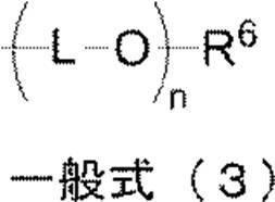
一般式(3)において、Lは炭素原子数2~6のアルキレン基を表し、R6は直鎖、分岐若しくは環状の炭素原子数4~8の無置換アルキル基又は芳香族置換アルキル基を表す。nはポリエーテルの平均付加モル数を表し、2~4の範囲である。 The protective layer is a protective layer containing a hydrophilic polymer containing at least a repeating unit represented by the following general formula (1) and a repeating unit represented by the following general formula (2). 5. The method according to any one of 4 above.
In General Formula (1) and General Formula (2), R 1 and R 4 each independently represent a hydrogen atom or a methyl group. R 2 and R 3 each independently represents a hydrogen atom, a methyl group, or an ethyl group. R 5 represents a linear, branched or cyclic unsubstituted alkyl group having 2 to 8 carbon atoms, a substituted alkyl group which may have an aromatic ring or a heterocyclic ring as a substituent, or a group represented by the following general formula (3): Represents a substituent.
In the general formula (3), L represents an alkylene group having 2 to 6 carbon atoms, and R 6 represents a linear, branched or cyclic unsubstituted alkyl group or aromatic substituted alkyl group having 4 to 8 carbon atoms. . n represents the average number of moles added of the polyether and is in the range of 2-4. - 前記親水性ポリマーが、さらに、下記一般式(4)で表される繰返し単位を含む、請求項5に記載の方法。
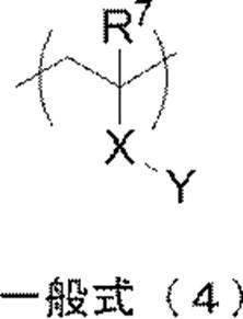
一般式(4)中、R7は、水素原子又はメチル基を表す。Xは単結合又は下記構造群(5)に示す構造から選ばれる二価の連結基であるか、又は、下記構造群(6)に示す構造から選ばれる複数を組み合わせてなる二価の連結基を表す。Yは、カルボン酸基、カルボン酸塩基、スルホン酸基、スルホン酸塩基、リン酸基、リン酸塩基、ホスホン酸基、ホスホン酸塩基、ヒドロキシル基、カルボキシベタイン基、スルホベタイン基、アンモニウム基、又は、下記一般式(7)で表されるポリエーテル基を表す。
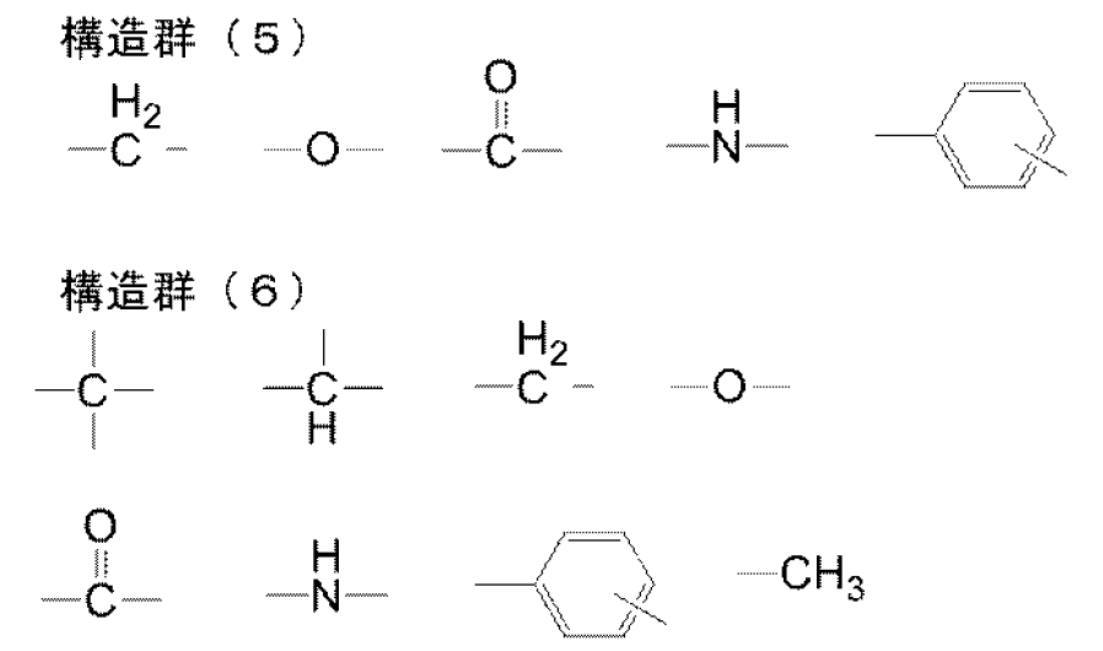
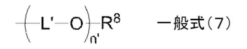
一般式(7)において、L’は炭素原子数2~3のアルキレン基、R8は水素原子又はメチル基を表す。n’はポリエーテルの平均付加モル数を表し、2~4の範囲である。 The method according to claim 5, wherein the hydrophilic polymer further contains a repeating unit represented by the following general formula (4).
In general formula (4), R 7 represents a hydrogen atom or a methyl group. X is a single bond or a divalent linking group selected from the structures shown in the following structural group (5), or a divalent linking group formed by combining a plurality selected from the structures shown in the following structural group (6). Represents. Y is a carboxylic acid group, a carboxylic acid group, a sulfonic acid group, a sulfonic acid group, a phosphoric acid group, a phosphoric acid group, a phosphonic acid group, a phosphonic acid group, a hydroxyl group, a carboxybetaine group, a sulfobetaine group, an ammonium group, or Represents a polyether group represented by the following general formula (7).
In the general formula (7), L ′ represents an alkylene group having 2 to 3 carbon atoms, and R 8 represents a hydrogen atom or a methyl group. n ′ represents the average number of moles added of the polyether and is in the range of 2-4. - 支持体上に(a)赤外線吸収染料、(b)重合開始剤、及び(c)重合性化合物、を含有するラジカル重合性の画像記録層と、保護層と、をこの順に有する感光性平版印刷版原版を露光後、現像する自動現像機の現像処理浴中で、該露光後の感光性平版印刷版原版を、ナフタレン骨格を有するアニオン性界面活性剤及びナフタレン骨格を有するノニオン性界面活性剤からなる群より選ばれる少なくとも一つを1質量%~10質量%含有し、沸点が100℃~300℃の範囲である有機溶剤の含有量が2質量%以下であり、pHが7.0~9.5である現像液により現像処理する工程、
前記現像処理工程において生じた現像処理廃液を、蒸発濃縮装置で、濃縮前の現像処理廃液の量に対する濃縮後の現像処理廃液の量の比が容量基準で1/2~1/10となるように、蒸発濃縮する工程、
前記蒸発濃縮工程において生じた水蒸気を冷却により凝縮して再生水を生成する工程、及び、
前記再生水を、前記自動現像機に供給する工程、
を含む感光性平版印刷版の現像処理廃液のリサイクル方法。 Photosensitive lithographic printing having a radically polymerizable image recording layer containing (a) an infrared absorbing dye, (b) a polymerization initiator, and (c) a polymerizable compound, and a protective layer in this order on a support. In the development processing bath of an automatic processor that develops the plate precursor after exposure, the exposed photosensitive lithographic printing plate precursor is converted from an anionic surfactant having a naphthalene skeleton and a nonionic surfactant having a naphthalene skeleton. The content of the organic solvent containing 1% by mass to 10% by mass of at least one selected from the group consisting of 2% by mass or less with a boiling point in the range of 100 ° C. to 300 ° C. and a pH of 7.0 to 9 A step of developing with a developer which is .5.
The ratio of the amount of the development processing waste liquid after the concentration to the amount of the development processing waste liquid before the concentration is reduced to 1/2 to 1/10 on a volume basis with the evaporation concentrating device. And evaporating and concentrating,
A step of condensing the water vapor generated in the evaporative concentration step by cooling to produce regenerated water, and
Supplying the recycled water to the automatic processor;
Recycling process waste liquid for photosensitive lithographic printing plate containing - 前記感光性平版印刷版原版を、前記現像処理工程後、水洗工程、及び不感脂化液による非画像部の不感脂化処理工程を経て、製版することを含む、請求項7に記載の方法。 The method according to claim 7, comprising making the photosensitive lithographic printing plate precursor through a washing step and a desensitizing treatment step for a non-image area with a desensitizing solution after the development processing step.
Priority Applications (4)
| Application Number | Priority Date | Filing Date | Title |
|---|---|---|---|
| JP2014522561A JP6081458B2 (en) | 2012-06-29 | 2013-06-18 | Development waste liquid concentration method and development waste liquid recycling method |
| CN201380033687.2A CN104395834B (en) | 2012-06-29 | 2013-06-18 | The method for recycling of development treatment waste liquid method for concentration and development treatment waste liquid |
| EP13808606.1A EP2869122A4 (en) | 2012-06-29 | 2013-06-18 | Method for concentrating processing waste liquid and method for recycling processing waste liquid |
| US14/574,394 US20150104746A1 (en) | 2012-06-29 | 2014-12-18 | Method of concentrating waste liquid produced by development, and method of recycling waste liquid produced by development |
Applications Claiming Priority (2)
| Application Number | Priority Date | Filing Date | Title |
|---|---|---|---|
| JP2012147791 | 2012-06-29 | ||
| JP2012-147791 | 2012-06-29 |
Related Child Applications (1)
| Application Number | Title | Priority Date | Filing Date |
|---|---|---|---|
| US14/574,394 Continuation US20150104746A1 (en) | 2012-06-29 | 2014-12-18 | Method of concentrating waste liquid produced by development, and method of recycling waste liquid produced by development |
Publications (1)
| Publication Number | Publication Date |
|---|---|
| WO2014002835A1 true WO2014002835A1 (en) | 2014-01-03 |
Family
ID=49782994
Family Applications (1)
| Application Number | Title | Priority Date | Filing Date |
|---|---|---|---|
| PCT/JP2013/066758 WO2014002835A1 (en) | 2012-06-29 | 2013-06-18 | Method for concentrating processing waste liquid and method for recycling processing waste liquid |
Country Status (5)
| Country | Link |
|---|---|
| US (1) | US20150104746A1 (en) |
| EP (1) | EP2869122A4 (en) |
| JP (1) | JP6081458B2 (en) |
| CN (1) | CN104395834B (en) |
| WO (1) | WO2014002835A1 (en) |
Families Citing this family (4)
| Publication number | Priority date | Publication date | Assignee | Title |
|---|---|---|---|---|
| JP6713658B2 (en) * | 2015-07-22 | 2020-06-24 | 株式会社平間理化研究所 | Component concentration measuring device for developer, component concentration measuring method, developer controlling device, and developer controlling method |
| CN109466201B (en) * | 2017-09-07 | 2020-10-27 | 乐凯华光印刷科技有限公司 | Regenerated flexible plate and preparation method thereof |
| JP7261869B2 (en) * | 2019-04-12 | 2023-04-20 | 富士フイルム株式会社 | Aqueous developer for flexographic printing plate and method for producing flexographic printing plate |
| CN114933675B (en) * | 2022-07-25 | 2022-10-04 | 潍坊金石环保科技有限公司 | Comprehensive utilization method of 2-acrylamide-2-methyl propanesulfonic acid distillation concentrate |
Citations (92)
| Publication number | Priority date | Publication date | Assignee | Title |
|---|---|---|---|---|
| US2714066A (en) | 1950-12-06 | 1955-07-26 | Minnesota Mining & Mfg | Planographic printing plate |
| US2833827A (en) | 1955-01-17 | 1958-05-06 | Bayer Ag | Tri (3, 5-di lower alkyl-4-hydroxy phenyl)-sulfonium chlorides and method of preparing same |
| US3181461A (en) | 1963-05-23 | 1965-05-04 | Howard A Fromson | Photographic plate |
| US3276868A (en) | 1960-08-05 | 1966-10-04 | Azoplate Corp | Planographic printing plates |
| US3280734A (en) | 1963-10-29 | 1966-10-25 | Howard A Fromson | Photographic plate |
| US3458311A (en) | 1966-06-27 | 1969-07-29 | Du Pont | Photopolymerizable elements with solvent removable protective layers |
| GB1303578A (en) | 1970-06-08 | 1973-01-17 | ||
| US3902734A (en) | 1974-03-14 | 1975-09-02 | Twm Mfg Co | Frames for axle suspension systems |
| US4069056A (en) | 1974-05-02 | 1978-01-17 | General Electric Company | Photopolymerizable composition containing group Va aromatic onium salts |
| US4069055A (en) | 1974-05-02 | 1978-01-17 | General Electric Company | Photocurable epoxy compositions containing group Va onium salts |
| JPS548002A (en) | 1977-06-17 | 1979-01-22 | Fuji Photo Film Co Ltd | Method of developing flat printing plate |
| US4153461A (en) | 1967-12-04 | 1979-05-08 | Hoechst Aktiengesellschaft | Layer support for light-sensitive material adapted to be converted into a planographic printing plate |
| JPS5412215B2 (en) | 1972-09-27 | 1979-05-21 | ||
| DE2904626A1 (en) | 1978-02-08 | 1979-08-09 | Minnesota Mining & Mfg | TRIARYLSULFONIUM COMPLEX SALTS, METHOD FOR THE PRODUCTION THEREOF AND PHOTOPOLYMERIZABLE MIXTURES CONTAINING THESE SALTS |
| JPS5549729A (en) | 1978-10-06 | 1980-04-10 | Nec Corp | Data transfer system |
| JPS55115045A (en) | 1979-02-27 | 1980-09-04 | Fuji Photo Film Co Ltd | Printing plate preparation |
| JPS5549729B2 (en) | 1973-02-07 | 1980-12-13 | ||
| EP0104143A1 (en) | 1982-09-18 | 1984-03-28 | Ciba-Geigy Ag | Photopolymerizable compositions containing diaryliodosyl salts |
| JPS5958431A (en) | 1982-09-29 | 1984-04-04 | Konishiroku Photo Ind Co Ltd | Photoengraving method of lithographic printing plate |
| JPS61166544A (en) | 1985-01-18 | 1986-07-28 | Fuji Photo Film Co Ltd | Photosolubilizable composition |
| DE3604581A1 (en) | 1986-02-14 | 1987-08-20 | Basf Ag | 4-Acylbenzylsulphonium salts, their preparation, and photocurable mixtures and recording materials containing these compounds |
| DE3604580A1 (en) | 1986-02-14 | 1987-08-20 | Basf Ag | CURABLE MIXTURES CONTAINING N-SULFONYLAMINOSULFONIUM SALTS AS CATIONICALLY EFFECTIVE CATALYSTS |
| US4689272A (en) | 1984-02-21 | 1987-08-25 | Hoechst Aktiengesellschaft | Process for a two-stage hydrophilizing post-treatment of aluminum oxide layers with aqueous solutions and use thereof in the manufacture of supports for offset printing plates |
| US4760013A (en) | 1987-02-17 | 1988-07-26 | International Business Machines Corporation | Sulfonium salt photoinitiators |
| EP0297442A1 (en) | 1987-07-01 | 1989-01-04 | BASF Aktiengesellschaft | Sulfonium salts comprising groups which are labile in acid environment |
| EP0297443A2 (en) | 1987-07-01 | 1989-01-04 | BASF Aktiengesellschaft | Light sensitive mixture for light sensitive coating materials |
| EP0370693A2 (en) | 1988-11-21 | 1990-05-30 | Eastman Kodak Company | Novel onium salts and the use thereof as photoinitiators |
| JPH02150848A (en) | 1988-12-02 | 1990-06-11 | Hitachi Ltd | Photofadable and radiation sensitive composition and pattern forming method by using this composition |
| US4933377A (en) | 1988-02-29 | 1990-06-12 | Saeva Franklin D | Novel sulfonium salts and the use thereof as photoinitiators |
| JPH02157084A (en) | 1988-01-12 | 1990-06-15 | Konica Corp | Treatment of non-silver salt photosensitive material improving in workability of waste liquid treatment and the like, and device therefor |
| EP0390214A2 (en) | 1989-03-31 | 1990-10-03 | E.F. Johnson Company | Method and apparatus for a distributive wide area network for a land mobile transmission trunked communication system |
| JPH02304441A (en) | 1989-05-18 | 1990-12-18 | Fuji Photo Film Co Ltd | Photosensitive planographic printing plate |
| JPH04365049A (en) | 1991-06-12 | 1992-12-17 | Fuji Photo Film Co Ltd | Photosensitive composition material |
| JPH055005A (en) | 1991-04-26 | 1993-01-14 | Kyowa Hakko Kogyo Co Ltd | Photopolymerization initiator and photopolymerizable composition containing the same |
| JPH0545885A (en) | 1991-08-19 | 1993-02-26 | Fuji Photo Film Co Ltd | Photosensitive planographic printing plate |
| JPH05341535A (en) | 1992-06-09 | 1993-12-24 | Fuji Photo Film Co Ltd | Method for recovering waste liquid from photosensitive planographic printing plate processor |
| JPH0635174A (en) | 1992-07-16 | 1994-02-10 | Fuji Photo Film Co Ltd | Photosensitive planographic printing plate and processing method for the same |
| JPH08108621A (en) | 1994-10-06 | 1996-04-30 | Konica Corp | Image recording medium and image forming method using the medium |
| JPH09123387A (en) | 1995-10-24 | 1997-05-13 | Agfa Gevaert Nv | Manufacture of lithographic printing plate including development on printing machine |
| JPH09131850A (en) | 1995-10-24 | 1997-05-20 | Agfa Gevaert Nv | Preparation of lithographic printing plate including development on press |
| JPH09171250A (en) | 1995-11-09 | 1997-06-30 | Agfa Gevaert Nv | Thermosensitive image formation element and method for manufacture of printing plate by using it |
| JPH09171249A (en) | 1995-11-09 | 1997-06-30 | Agfa Gevaert Nv | Thermosensitive image formation element and method for manufacture of printing plate by using it |
| JPH09179298A (en) | 1995-12-22 | 1997-07-11 | Mitsubishi Chem Corp | Photopolymerizable composition |
| JPH09179297A (en) | 1995-12-22 | 1997-07-11 | Mitsubishi Chem Corp | Photopolymerizable composition |
| JPH09179296A (en) | 1995-12-22 | 1997-07-11 | Mitsubishi Chem Corp | Photopolymerizable composition |
| JPH10282679A (en) | 1997-04-08 | 1998-10-23 | Fuji Photo Film Co Ltd | Negative type photosensitive planographic printing plate |
| JPH10333321A (en) | 1997-06-03 | 1998-12-18 | Mitsubishi Chem Corp | Photosensitive planographic printing plate developed by printing and photomechanical process for the same |
| JPH1165126A (en) * | 1997-08-13 | 1999-03-05 | Mitsubishi Chem Corp | Developing method of photosensitive lithographic printing plate and developer to be used for the method |
| EP0931647A1 (en) | 1998-01-23 | 1999-07-28 | Agfa-Gevaert N.V. | A heat sensitive element and a method for producing lithographic plates therewith |
| JP2001133969A (en) | 1999-11-01 | 2001-05-18 | Fuji Photo Film Co Ltd | Negative type original plate of planographic printing plate |
| JP2001222101A (en) | 2000-02-09 | 2001-08-17 | Mitsubishi Paper Mills Ltd | Photosensitive composition and photosensitive planographic printing plate material |
| JP2001253181A (en) | 2000-03-09 | 2001-09-18 | Fuji Photo Film Co Ltd | Original plate for positive type heat sensitive lithographic printing |
| JP2001277742A (en) | 2000-01-27 | 2001-10-10 | Fuji Photo Film Co Ltd | Original plate for lithographic printing plate |
| JP2001277740A (en) | 2000-01-27 | 2001-10-10 | Fuji Photo Film Co Ltd | Original plate for lithographic printing plate |
| JP2001322365A (en) | 2000-05-16 | 2001-11-20 | Fuji Photo Film Co Ltd | Original plate for heat-sensitive lithographic printing |
| JP2001342222A (en) | 2000-03-30 | 2001-12-11 | Mitsubishi Chemicals Corp | Photocurable composition, low birefringent optical member and method for producing the same composition |
| JP2002023360A (en) | 2000-07-12 | 2002-01-23 | Fuji Photo Film Co Ltd | Negative type image recording material |
| JP2002040638A (en) | 2000-07-25 | 2002-02-06 | Fuji Photo Film Co Ltd | Negative-type image recording material and image- forming method |
| JP2002275129A (en) | 2001-03-14 | 2002-09-25 | Fuji Photo Film Co Ltd | Radical-polymerizable compound |
| JP2002278057A (en) | 2001-01-15 | 2002-09-27 | Fuji Photo Film Co Ltd | Negative type image recording material and cyanine dye |
| JP2002287344A (en) | 2001-03-27 | 2002-10-03 | Fuji Photo Film Co Ltd | Photopolymerizable planographic printing plate |
| JP2002328465A (en) | 2001-04-27 | 2002-11-15 | Fuji Photo Film Co Ltd | Original plate of planographic printing plate |
| JP2003064130A (en) | 2001-08-29 | 2003-03-05 | Fuji Photo Film Co Ltd | Photo-polymerizable composition |
| JP2003228175A (en) * | 2002-02-04 | 2003-08-15 | Konica Corp | Treating method for photosensitive planographic printing plate and developing solution for photosensitive planographic printing plate |
| JP2003280187A (en) | 2002-03-25 | 2003-10-02 | Fuji Photo Film Co Ltd | Photopolymerizable composition |
| JP2004294935A (en) | 2003-03-28 | 2004-10-21 | Mitsubishi Paper Mills Ltd | Photosensitive composition and photosensitive lithographic printing plate material |
| JP2005119273A (en) | 2003-09-24 | 2005-05-12 | Fuji Photo Film Co Ltd | Lithographic printing original plate and lithographic printing method |
| JP2005125749A (en) | 2003-09-30 | 2005-05-19 | Fuji Photo Film Co Ltd | Lithographic form original plate |
| JP2005238816A (en) | 2003-07-22 | 2005-09-08 | Fuji Photo Film Co Ltd | Original plate for lithographic printing plate, and lithographic printing method |
| JP2005250216A (en) | 2004-03-05 | 2005-09-15 | Fuji Photo Film Co Ltd | Original plate for negative planographic printing plate and method of manufacturing planographic printing plate |
| JP2006508380A (en) | 2002-11-28 | 2006-03-09 | コダック ポリクロウム グラフィクス ゲゼルシャフト ミット ベシュレンクテル ハフツング | Radiation sensitive element |
| JP2006091479A (en) | 2004-09-24 | 2006-04-06 | Fuji Photo Film Co Ltd | Photosensitive lithographic printing plate |
| JP2006188038A (en) | 2004-12-10 | 2006-07-20 | Fuji Photo Film Co Ltd | Original lithographic printing plate and plate manufacturing method |
| JP2006215263A (en) | 2005-02-03 | 2006-08-17 | Fuji Photo Film Co Ltd | Lithographic printing original plate |
| JP2006243493A (en) | 2005-03-04 | 2006-09-14 | Fuji Photo Film Co Ltd | Photosensitive lithographic printing plate |
| JP2006239867A (en) | 2005-02-28 | 2006-09-14 | Fuji Photo Film Co Ltd | Original lithographic printing plate and lithographic printing method |
| JP2006259137A (en) | 2005-03-16 | 2006-09-28 | Fuji Photo Film Co Ltd | Negative lithographic printing forme original plate |
| JP2007090850A (en) | 2005-08-29 | 2007-04-12 | Fujifilm Corp | Lithographic printing plate precursor, lithographic printing method and novel cyanine dye |
| JP2007276454A (en) | 2006-03-14 | 2007-10-25 | Fujifilm Corp | Lithographic printing plate original plate |
| JP2008025685A (en) | 2006-07-20 | 2008-02-07 | Nsk Ltd | Rolling bearing |
| JP2008080229A (en) * | 2006-09-27 | 2008-04-10 | Toyobo Co Ltd | Method for treating waste developing solution of water-developable photosensitive resin developer |
| JP2008195018A (en) | 2007-02-15 | 2008-08-28 | Fujifilm Corp | Original plate of lithographic printing plate and lithographic printing method |
| JP2008284817A (en) | 2007-05-18 | 2008-11-27 | Fujifilm Corp | Planographic printing original plate and printing method using the same |
| US20080311520A1 (en) | 2007-06-13 | 2008-12-18 | Jianfei Yu | On-press developable negative-working imageable elements and methods of use |
| JP2009154525A (en) | 2007-10-29 | 2009-07-16 | Fujifilm Corp | Lithographic printing original plate |
| JP2010079083A (en) * | 2008-09-26 | 2010-04-08 | Fujifilm Corp | Plate making method of lithographic printing plate |
| JP2010537238A (en) * | 2007-08-23 | 2010-12-02 | イーストマン コダック カンパニー | Treatment of lithographic printing plate with developer containing hydrophilic polymer |
| JP2011090282A (en) | 2009-09-25 | 2011-05-06 | Fujifilm Corp | Method for processing waste solution in plate-making process of photosensitive lithographic printing plate |
| JP4774124B1 (en) | 2009-09-24 | 2011-09-14 | 富士フイルムグラフィックシステムズ株式会社 | Lithographic printing plate development waste reduction device |
| EP2383118A2 (en) | 2010-04-30 | 2011-11-02 | Fujifilm Corporation | Lithographic printing plate precursor, plate making method thereof and polyvalent isocyanate compound |
| JP2012073597A (en) | 2010-08-31 | 2012-04-12 | Fujifilm Corp | Lithographic printing original plate and plate-making method thereof |
| JP2012147791A (en) | 2009-01-06 | 2012-08-09 | Functional Genetics Inc | Random homozygous gene perturbation (rhgp) with thermal assymetric interlaced (tail)-pcr |
Family Cites Families (10)
| Publication number | Priority date | Publication date | Assignee | Title |
|---|---|---|---|---|
| US7074546B2 (en) * | 2002-06-24 | 2006-07-11 | Konica Corporation | Light sensitive planographic printing plate precursor and its processing method |
| JP5216214B2 (en) * | 2003-12-19 | 2013-06-19 | 富士フイルム株式会社 | Ink jet ink, ink jet ink manufacturing method, ink jet ink set, and ink jet recording method |
| DE602005009617D1 (en) * | 2004-07-29 | 2008-10-23 | Fujifilm Corp | Process for the production of lithographic printing plates |
| JP2009222938A (en) * | 2008-03-14 | 2009-10-01 | Fujifilm Corp | Lithographic printing plate precursor |
| JP4997201B2 (en) * | 2008-09-05 | 2012-08-08 | 富士フイルム株式会社 | Preparation method of lithographic printing plate |
| EP2339401B1 (en) * | 2009-12-28 | 2016-02-17 | Fujifilm Corporation | Method of preparing lithographic printing plate |
| JP2012071557A (en) * | 2010-09-29 | 2012-04-12 | Fujifilm Corp | Lithographic printing plate precursor, lithographic printing method, and organic clay composite |
| JP2012176606A (en) * | 2011-02-02 | 2012-09-13 | Fujifilm Corp | Lithographic printing original plate and method for producing the same |
| JP5244987B2 (en) * | 2011-02-28 | 2013-07-24 | 富士フイルム株式会社 | Planographic printing plate precursor and plate making method |
| JP5604398B2 (en) * | 2011-09-30 | 2014-10-08 | 富士フイルム株式会社 | Planographic printing plate precursor and lithographic printing plate preparation method |
-
2013
- 2013-06-18 JP JP2014522561A patent/JP6081458B2/en active Active
- 2013-06-18 WO PCT/JP2013/066758 patent/WO2014002835A1/en active Application Filing
- 2013-06-18 CN CN201380033687.2A patent/CN104395834B/en active Active
- 2013-06-18 EP EP13808606.1A patent/EP2869122A4/en not_active Withdrawn
-
2014
- 2014-12-18 US US14/574,394 patent/US20150104746A1/en not_active Abandoned
Patent Citations (94)
| Publication number | Priority date | Publication date | Assignee | Title |
|---|---|---|---|---|
| US2714066A (en) | 1950-12-06 | 1955-07-26 | Minnesota Mining & Mfg | Planographic printing plate |
| US2833827A (en) | 1955-01-17 | 1958-05-06 | Bayer Ag | Tri (3, 5-di lower alkyl-4-hydroxy phenyl)-sulfonium chlorides and method of preparing same |
| US3276868A (en) | 1960-08-05 | 1966-10-04 | Azoplate Corp | Planographic printing plates |
| US3181461A (en) | 1963-05-23 | 1965-05-04 | Howard A Fromson | Photographic plate |
| US3280734A (en) | 1963-10-29 | 1966-10-25 | Howard A Fromson | Photographic plate |
| US3458311A (en) | 1966-06-27 | 1969-07-29 | Du Pont | Photopolymerizable elements with solvent removable protective layers |
| US4153461A (en) | 1967-12-04 | 1979-05-08 | Hoechst Aktiengesellschaft | Layer support for light-sensitive material adapted to be converted into a planographic printing plate |
| GB1303578A (en) | 1970-06-08 | 1973-01-17 | ||
| JPS5412215B2 (en) | 1972-09-27 | 1979-05-21 | ||
| JPS5549729B2 (en) | 1973-02-07 | 1980-12-13 | ||
| US3902734A (en) | 1974-03-14 | 1975-09-02 | Twm Mfg Co | Frames for axle suspension systems |
| US4069055A (en) | 1974-05-02 | 1978-01-17 | General Electric Company | Photocurable epoxy compositions containing group Va onium salts |
| US4069056A (en) | 1974-05-02 | 1978-01-17 | General Electric Company | Photopolymerizable composition containing group Va aromatic onium salts |
| JPS548002A (en) | 1977-06-17 | 1979-01-22 | Fuji Photo Film Co Ltd | Method of developing flat printing plate |
| DE2904626A1 (en) | 1978-02-08 | 1979-08-09 | Minnesota Mining & Mfg | TRIARYLSULFONIUM COMPLEX SALTS, METHOD FOR THE PRODUCTION THEREOF AND PHOTOPOLYMERIZABLE MIXTURES CONTAINING THESE SALTS |
| JPS5549729A (en) | 1978-10-06 | 1980-04-10 | Nec Corp | Data transfer system |
| JPS55115045A (en) | 1979-02-27 | 1980-09-04 | Fuji Photo Film Co Ltd | Printing plate preparation |
| EP0104143A1 (en) | 1982-09-18 | 1984-03-28 | Ciba-Geigy Ag | Photopolymerizable compositions containing diaryliodosyl salts |
| JPS5958431A (en) | 1982-09-29 | 1984-04-04 | Konishiroku Photo Ind Co Ltd | Photoengraving method of lithographic printing plate |
| US4689272A (en) | 1984-02-21 | 1987-08-25 | Hoechst Aktiengesellschaft | Process for a two-stage hydrophilizing post-treatment of aluminum oxide layers with aqueous solutions and use thereof in the manufacture of supports for offset printing plates |
| JPS61166544A (en) | 1985-01-18 | 1986-07-28 | Fuji Photo Film Co Ltd | Photosolubilizable composition |
| DE3604581A1 (en) | 1986-02-14 | 1987-08-20 | Basf Ag | 4-Acylbenzylsulphonium salts, their preparation, and photocurable mixtures and recording materials containing these compounds |
| DE3604580A1 (en) | 1986-02-14 | 1987-08-20 | Basf Ag | CURABLE MIXTURES CONTAINING N-SULFONYLAMINOSULFONIUM SALTS AS CATIONICALLY EFFECTIVE CATALYSTS |
| EP0233567A2 (en) | 1986-02-14 | 1987-08-26 | BASF Aktiengesellschaft | Curable compositions containing N-sulfonylaminosulfonium salts as cationically active catalysts |
| US4734444A (en) | 1986-02-14 | 1988-03-29 | Basf Aktiengesellschaft | Curable mixtures containing N-sulfonylaminosulfonium salts as cationically active catalysts |
| US4760013A (en) | 1987-02-17 | 1988-07-26 | International Business Machines Corporation | Sulfonium salt photoinitiators |
| EP0297442A1 (en) | 1987-07-01 | 1989-01-04 | BASF Aktiengesellschaft | Sulfonium salts comprising groups which are labile in acid environment |
| EP0297443A2 (en) | 1987-07-01 | 1989-01-04 | BASF Aktiengesellschaft | Light sensitive mixture for light sensitive coating materials |
| JPH02157084A (en) | 1988-01-12 | 1990-06-15 | Konica Corp | Treatment of non-silver salt photosensitive material improving in workability of waste liquid treatment and the like, and device therefor |
| US4933377A (en) | 1988-02-29 | 1990-06-12 | Saeva Franklin D | Novel sulfonium salts and the use thereof as photoinitiators |
| EP0370693A2 (en) | 1988-11-21 | 1990-05-30 | Eastman Kodak Company | Novel onium salts and the use thereof as photoinitiators |
| JPH02150848A (en) | 1988-12-02 | 1990-06-11 | Hitachi Ltd | Photofadable and radiation sensitive composition and pattern forming method by using this composition |
| EP0390214A2 (en) | 1989-03-31 | 1990-10-03 | E.F. Johnson Company | Method and apparatus for a distributive wide area network for a land mobile transmission trunked communication system |
| JPH02304441A (en) | 1989-05-18 | 1990-12-18 | Fuji Photo Film Co Ltd | Photosensitive planographic printing plate |
| JPH055005A (en) | 1991-04-26 | 1993-01-14 | Kyowa Hakko Kogyo Co Ltd | Photopolymerization initiator and photopolymerizable composition containing the same |
| JPH04365049A (en) | 1991-06-12 | 1992-12-17 | Fuji Photo Film Co Ltd | Photosensitive composition material |
| JPH0545885A (en) | 1991-08-19 | 1993-02-26 | Fuji Photo Film Co Ltd | Photosensitive planographic printing plate |
| JPH05341535A (en) | 1992-06-09 | 1993-12-24 | Fuji Photo Film Co Ltd | Method for recovering waste liquid from photosensitive planographic printing plate processor |
| JPH0635174A (en) | 1992-07-16 | 1994-02-10 | Fuji Photo Film Co Ltd | Photosensitive planographic printing plate and processing method for the same |
| JPH08108621A (en) | 1994-10-06 | 1996-04-30 | Konica Corp | Image recording medium and image forming method using the medium |
| JPH09123387A (en) | 1995-10-24 | 1997-05-13 | Agfa Gevaert Nv | Manufacture of lithographic printing plate including development on printing machine |
| JPH09131850A (en) | 1995-10-24 | 1997-05-20 | Agfa Gevaert Nv | Preparation of lithographic printing plate including development on press |
| JPH09171250A (en) | 1995-11-09 | 1997-06-30 | Agfa Gevaert Nv | Thermosensitive image formation element and method for manufacture of printing plate by using it |
| JPH09171249A (en) | 1995-11-09 | 1997-06-30 | Agfa Gevaert Nv | Thermosensitive image formation element and method for manufacture of printing plate by using it |
| JPH09179296A (en) | 1995-12-22 | 1997-07-11 | Mitsubishi Chem Corp | Photopolymerizable composition |
| JPH09179297A (en) | 1995-12-22 | 1997-07-11 | Mitsubishi Chem Corp | Photopolymerizable composition |
| JPH09179298A (en) | 1995-12-22 | 1997-07-11 | Mitsubishi Chem Corp | Photopolymerizable composition |
| JPH10282679A (en) | 1997-04-08 | 1998-10-23 | Fuji Photo Film Co Ltd | Negative type photosensitive planographic printing plate |
| JPH10333321A (en) | 1997-06-03 | 1998-12-18 | Mitsubishi Chem Corp | Photosensitive planographic printing plate developed by printing and photomechanical process for the same |
| JPH1165126A (en) * | 1997-08-13 | 1999-03-05 | Mitsubishi Chem Corp | Developing method of photosensitive lithographic printing plate and developer to be used for the method |
| EP0931647A1 (en) | 1998-01-23 | 1999-07-28 | Agfa-Gevaert N.V. | A heat sensitive element and a method for producing lithographic plates therewith |
| JP2001133969A (en) | 1999-11-01 | 2001-05-18 | Fuji Photo Film Co Ltd | Negative type original plate of planographic printing plate |
| JP2001277742A (en) | 2000-01-27 | 2001-10-10 | Fuji Photo Film Co Ltd | Original plate for lithographic printing plate |
| JP2001277740A (en) | 2000-01-27 | 2001-10-10 | Fuji Photo Film Co Ltd | Original plate for lithographic printing plate |
| JP2001222101A (en) | 2000-02-09 | 2001-08-17 | Mitsubishi Paper Mills Ltd | Photosensitive composition and photosensitive planographic printing plate material |
| JP2001253181A (en) | 2000-03-09 | 2001-09-18 | Fuji Photo Film Co Ltd | Original plate for positive type heat sensitive lithographic printing |
| JP2001342222A (en) | 2000-03-30 | 2001-12-11 | Mitsubishi Chemicals Corp | Photocurable composition, low birefringent optical member and method for producing the same composition |
| JP2001322365A (en) | 2000-05-16 | 2001-11-20 | Fuji Photo Film Co Ltd | Original plate for heat-sensitive lithographic printing |
| JP2002023360A (en) | 2000-07-12 | 2002-01-23 | Fuji Photo Film Co Ltd | Negative type image recording material |
| JP2002040638A (en) | 2000-07-25 | 2002-02-06 | Fuji Photo Film Co Ltd | Negative-type image recording material and image- forming method |
| JP2002278057A (en) | 2001-01-15 | 2002-09-27 | Fuji Photo Film Co Ltd | Negative type image recording material and cyanine dye |
| JP2002275129A (en) | 2001-03-14 | 2002-09-25 | Fuji Photo Film Co Ltd | Radical-polymerizable compound |
| JP2002287344A (en) | 2001-03-27 | 2002-10-03 | Fuji Photo Film Co Ltd | Photopolymerizable planographic printing plate |
| JP2002328465A (en) | 2001-04-27 | 2002-11-15 | Fuji Photo Film Co Ltd | Original plate of planographic printing plate |
| JP2003064130A (en) | 2001-08-29 | 2003-03-05 | Fuji Photo Film Co Ltd | Photo-polymerizable composition |
| JP2003228175A (en) * | 2002-02-04 | 2003-08-15 | Konica Corp | Treating method for photosensitive planographic printing plate and developing solution for photosensitive planographic printing plate |
| JP2003280187A (en) | 2002-03-25 | 2003-10-02 | Fuji Photo Film Co Ltd | Photopolymerizable composition |
| JP2006508380A (en) | 2002-11-28 | 2006-03-09 | コダック ポリクロウム グラフィクス ゲゼルシャフト ミット ベシュレンクテル ハフツング | Radiation sensitive element |
| JP2004294935A (en) | 2003-03-28 | 2004-10-21 | Mitsubishi Paper Mills Ltd | Photosensitive composition and photosensitive lithographic printing plate material |
| JP2005238816A (en) | 2003-07-22 | 2005-09-08 | Fuji Photo Film Co Ltd | Original plate for lithographic printing plate, and lithographic printing method |
| JP2005119273A (en) | 2003-09-24 | 2005-05-12 | Fuji Photo Film Co Ltd | Lithographic printing original plate and lithographic printing method |
| JP2005125749A (en) | 2003-09-30 | 2005-05-19 | Fuji Photo Film Co Ltd | Lithographic form original plate |
| JP2005250216A (en) | 2004-03-05 | 2005-09-15 | Fuji Photo Film Co Ltd | Original plate for negative planographic printing plate and method of manufacturing planographic printing plate |
| JP2006091479A (en) | 2004-09-24 | 2006-04-06 | Fuji Photo Film Co Ltd | Photosensitive lithographic printing plate |
| JP2006188038A (en) | 2004-12-10 | 2006-07-20 | Fuji Photo Film Co Ltd | Original lithographic printing plate and plate manufacturing method |
| JP2006215263A (en) | 2005-02-03 | 2006-08-17 | Fuji Photo Film Co Ltd | Lithographic printing original plate |
| JP2006239867A (en) | 2005-02-28 | 2006-09-14 | Fuji Photo Film Co Ltd | Original lithographic printing plate and lithographic printing method |
| JP2006243493A (en) | 2005-03-04 | 2006-09-14 | Fuji Photo Film Co Ltd | Photosensitive lithographic printing plate |
| JP2006259137A (en) | 2005-03-16 | 2006-09-28 | Fuji Photo Film Co Ltd | Negative lithographic printing forme original plate |
| JP2007090850A (en) | 2005-08-29 | 2007-04-12 | Fujifilm Corp | Lithographic printing plate precursor, lithographic printing method and novel cyanine dye |
| JP2007276454A (en) | 2006-03-14 | 2007-10-25 | Fujifilm Corp | Lithographic printing plate original plate |
| JP2008025685A (en) | 2006-07-20 | 2008-02-07 | Nsk Ltd | Rolling bearing |
| JP2008080229A (en) * | 2006-09-27 | 2008-04-10 | Toyobo Co Ltd | Method for treating waste developing solution of water-developable photosensitive resin developer |
| JP2008195018A (en) | 2007-02-15 | 2008-08-28 | Fujifilm Corp | Original plate of lithographic printing plate and lithographic printing method |
| JP2008284817A (en) | 2007-05-18 | 2008-11-27 | Fujifilm Corp | Planographic printing original plate and printing method using the same |
| US20080311520A1 (en) | 2007-06-13 | 2008-12-18 | Jianfei Yu | On-press developable negative-working imageable elements and methods of use |
| JP2010537238A (en) * | 2007-08-23 | 2010-12-02 | イーストマン コダック カンパニー | Treatment of lithographic printing plate with developer containing hydrophilic polymer |
| JP2009154525A (en) | 2007-10-29 | 2009-07-16 | Fujifilm Corp | Lithographic printing original plate |
| JP2010079083A (en) * | 2008-09-26 | 2010-04-08 | Fujifilm Corp | Plate making method of lithographic printing plate |
| JP2012147791A (en) | 2009-01-06 | 2012-08-09 | Functional Genetics Inc | Random homozygous gene perturbation (rhgp) with thermal assymetric interlaced (tail)-pcr |
| JP4774124B1 (en) | 2009-09-24 | 2011-09-14 | 富士フイルムグラフィックシステムズ株式会社 | Lithographic printing plate development waste reduction device |
| JP2011090282A (en) | 2009-09-25 | 2011-05-06 | Fujifilm Corp | Method for processing waste solution in plate-making process of photosensitive lithographic printing plate |
| EP2383118A2 (en) | 2010-04-30 | 2011-11-02 | Fujifilm Corporation | Lithographic printing plate precursor, plate making method thereof and polyvalent isocyanate compound |
| JP2012073597A (en) | 2010-08-31 | 2012-04-12 | Fujifilm Corp | Lithographic printing original plate and plate-making method thereof |
Non-Patent Citations (6)
| Title |
|---|
| C. S. WEN ET AL., TEH, PROC. CONF, RAD. CURING ASIA, October 1988 (1988-10-01), pages 478 |
| J. V. CRIVELLO ET AL., MACROMOLECULES, vol. 10, no. 6, 1977, pages 1307 |
| J. V. CRIVELLO ET AL.: "J. Polymer Sci., Polymer Chem.", vol. 17, 1979, pages: 1047 |
| S. I. SCHLESINGER, PHOTOGR. SCI. ENG., vol. 18, 1974, pages 387 |
| See also references of EP2869122A4 |
| T. S. BAL ET AL., POLYMER, vol. 21, 1980, pages 423 |
Also Published As
| Publication number | Publication date |
|---|---|
| CN104395834A (en) | 2015-03-04 |
| EP2869122A4 (en) | 2016-03-02 |
| JP6081458B2 (en) | 2017-02-15 |
| JPWO2014002835A1 (en) | 2016-05-30 |
| US20150104746A1 (en) | 2015-04-16 |
| CN104395834B (en) | 2019-07-05 |
| EP2869122A1 (en) | 2015-05-06 |
Similar Documents
| Publication | Publication Date | Title |
|---|---|---|
| US11370862B2 (en) | Radiation-sensitive composition, planographic printing plate precursor, and plate-making method for planographic printing plate | |
| JP7220760B2 (en) | Lithographic printing plate precursor and method for preparing lithographic printing plate | |
| JP5715936B2 (en) | Planographic printing plate precursor and planographic printing method | |
| JP6427555B2 (en) | Processing method and printing method for on-press development type lithographic printing plate precursor | |
| WO2017145476A1 (en) | Method for producing lithographic printing plate | |
| JP5695267B2 (en) | Method for concentrating and recycling platemaking wastewater | |
| JP2012031400A (en) | New polymerizable composition, polymerizable compound to be used for the same, image-forming material and lithographic printing plate precursor using the new polymerizable composition | |
| JP6081458B2 (en) | Development waste liquid concentration method and development waste liquid recycling method | |
| JP5579217B2 (en) | Planographic printing plate precursor | |
| WO2011118457A1 (en) | Master planographic printing plate and manufacturing method therefor | |
| CN110891797B (en) | Method for making lithographic printing plate | |
| EP2757417B1 (en) | Method for recycling wastewater produced by plate-making process | |
| JP5740275B2 (en) | Printing method using on-press development type lithographic printing plate precursor | |
| JP2011073370A (en) | Lithographic printing original plate and plate making method for the same | |
| WO2014031582A1 (en) | Negative-working lithographic printing plate precursors and use | |
| JP5656784B2 (en) | Polymerizable composition, lithographic printing plate precursor using the same, and lithographic printing method | |
| JPWO2018159087A1 (en) | Method of preparing a lithographic printing plate | |
| JP6133261B2 (en) | Planographic printing plate precursor and lithographic printing plate making method | |
| WO2019064974A1 (en) | Lithographic printing plate precursor and lithographic printing plate fabrication method | |
| EP2762977B1 (en) | Method for recycling plate-making processing waste solution | |
| JP2010234649A (en) | Lithographic printing original plate, and method for manufacturing lithographic printing plate | |
| WO2015146716A1 (en) | Lithographic printing method | |
| JP5453023B2 (en) | Printing fountain solution and planographic printing plate printing method | |
| JP2010234585A (en) | Polymerizable composition, lithographic printing plate precursor, and plate making method | |
| EP3002124A1 (en) | Lithographic printing plate precursor and process for making lithographic printing plate |
Legal Events
| Date | Code | Title | Description |
|---|---|---|---|
| 121 | Ep: the epo has been informed by wipo that ep was designated in this application |
Ref document number: 13808606 Country of ref document: EP Kind code of ref document: A1 |
|
| ENP | Entry into the national phase |
Ref document number: 2014522561 Country of ref document: JP Kind code of ref document: A |
|
| REEP | Request for entry into the european phase |
Ref document number: 2013808606 Country of ref document: EP |
|
| WWE | Wipo information: entry into national phase |
Ref document number: 2013808606 Country of ref document: EP |
|
| NENP | Non-entry into the national phase |
Ref country code: DE |