WO2014064964A1 - Optical scanning device and light source device - Google Patents
Optical scanning device and light source device Download PDFInfo
- Publication number
- WO2014064964A1 WO2014064964A1 PCT/JP2013/067208 JP2013067208W WO2014064964A1 WO 2014064964 A1 WO2014064964 A1 WO 2014064964A1 JP 2013067208 W JP2013067208 W JP 2013067208W WO 2014064964 A1 WO2014064964 A1 WO 2014064964A1
- Authority
- WO
- WIPO (PCT)
- Prior art keywords
- light
- laser light
- pattern
- mirror
- laser
- Prior art date
Links
Images


Classifications
-
- G—PHYSICS
- G02—OPTICS
- G02B—OPTICAL ELEMENTS, SYSTEMS OR APPARATUS
- G02B27/00—Optical systems or apparatus not provided for by any of the groups G02B1/00 - G02B26/00, G02B30/00
- G02B27/48—Laser speckle optics
-
- G—PHYSICS
- G02—OPTICS
- G02B—OPTICAL ELEMENTS, SYSTEMS OR APPARATUS
- G02B26/00—Optical devices or arrangements for the control of light using movable or deformable optical elements
- G02B26/08—Optical devices or arrangements for the control of light using movable or deformable optical elements for controlling the direction of light
- G02B26/10—Scanning systems
- G02B26/105—Scanning systems with one or more pivoting mirrors or galvano-mirrors
-
- H—ELECTRICITY
- H04—ELECTRIC COMMUNICATION TECHNIQUE
- H04N—PICTORIAL COMMUNICATION, e.g. TELEVISION
- H04N9/00—Details of colour television systems
- H04N9/12—Picture reproducers
- H04N9/31—Projection devices for colour picture display, e.g. using electronic spatial light modulators [ESLM]
- H04N9/3129—Projection devices for colour picture display, e.g. using electronic spatial light modulators [ESLM] scanning a light beam on the display screen
Definitions
- the present invention relates to an optical scanning device and a light source device.
- Speckle noise is a phenomenon in which scattered light interferes with a human retina due to scattering of laser light due to unevenness of a screen or the like, thereby causing image flicker or the like.
- the present invention has been made to solve the above problems, and an object thereof is to provide an optical scanning device capable of stably reducing speckle noise and a light source device using the same.
- an optical scanning device includes a first collimating lens that collimates laser light modulated by a projection signal, and laser light that has been collimated by the first collimating lens.
- a signal scanning drive mirror that scans toward the object, and a light transmitting member in which a light non-transmitting portion is arranged in a predetermined pattern in front of the first collimating lens;
- a pattern modulation drive mirror that scans toward the member is arranged.
- the position where the laser light passes through the light transmitting member can be scanned by using the pattern modulation drive mirror.
- the pattern of the light non-transmission portion in the laser light transmission region changes depending on the position of the laser light with respect to the light transmission member.
- the luminance pattern of the laser light changes with time, even if the laser light from the optical scanning device is scattered by a screen or the like, interference in the human retina is suppressed and speckle noise can be reduced.
- the luminance pattern of the laser light can be changed stably as compared with the case where the light transmitting member itself is driven at a high speed.
- the signal scanning drive mirror and the pattern modulation drive mirror are MEMS mirrors, and the drive frequency of the pattern modulation drive mirror is preferably higher than the drive frequency of the signal scan drive mirror.
- the MEMS mirror as the signal scanning drive mirror and the pattern modulation drive mirror, both mirrors can be driven stably at a high frequency.
- the drive frequency of the pattern modulation drive mirror higher than the drive frequency of the signal scanning drive mirror, the change rate of the laser light luminance pattern can be sufficiently secured relative to the scanning speed of the projection signal, and the spec. Noise can be reduced more reliably.
- a drive unit that drives the light transmitting member in a direction crossing the optical axis of the laser beam.
- a second collimating lens for collimating the laser light reflected by the pattern modulation drive mirror is disposed between the pattern modulation drive mirror and the light transmission member. It is preferable that a first condensing lens that condenses the laser light transmitted through the transmissive member toward the first collimating lens is disposed.
- the laser light passing through the light transmitting member can be parallel light having a certain diameter. Therefore, the laser beam can be more reliably passed through the pattern of the light non-transmissive portion.
- a light source device includes the optical scanning device, a plurality of light sources that emit laser light, and a second condenser lens that condenses the light emitted from the light source toward the pattern modulation drive mirror. It is characterized by having.
- the position where the laser light passes through the light transmitting member can be scanned by using the pattern modulation drive mirror.
- the pattern of the light non-transmission portion in the laser light transmission region changes depending on the position of the laser light with respect to the light transmission member.
- speckle noise can be stably reduced.
- FIG. 1 is a diagram showing an embodiment of a light source device to which an optical scanning device according to the present invention is applied.
- the light source device 1 includes a plurality of light sources 2, a condenser lens (second condenser lens) 3, and an optical scanning device 4.
- the light source device 1 is used, for example, as an optical engine of a laser projector device, and displays an image on a screen (object) P by scanning a laser beam modulated by a projection signal by driving a mirror. It is.
- the light source 2 is composed of units of light sources 2a, 2b, and 2c that emit laser light corresponding to wavelengths of RGB colors.
- the laser beams emitted from the light sources 2 a, 2 b, 2 c are combined by the half mirrors 5, 6 and guided to the condenser lens 3.
- the condensing lens 3 is disposed at the subsequent stage of the half mirror 6.
- the condensing lens 3 condenses the synthesized laser light toward a pattern modulation drive mirror 16 described later.
- the light source 2 may be provided with a polarizing filter or an interference filter (bandpass filter) that cuts the return light. By cutting the return light, it is possible to prevent the light source 2 from being defective.
- the optical scanning device 4 incorporated in the light source device 1 includes a collimating lens (first collimating lens) 11 and a signal scanning drive mirror 12 as a configuration for scanning the screen P with laser light.
- the optical scanning device 4 includes a collimating lens (second collimating lens) 13 and a condensing lens (first condensing lens) 14 as a configuration for performing pattern modulation of laser light incident from the light source device 1. And a light transmission member 15 and a pattern modulation drive mirror 16.
- the collimating lens 11 is a lens that collimates the laser light modulated by the projection signal.
- the collimator lens 11 is arranged at the rear stage of the condenser lens 14, and collimates the laser light collected by the condenser lens 14 so as to enter the signal scanning drive mirror 12.
- the signal scanning drive mirror 12 is an electromagnetically driven optical mirror manufactured using, for example, MEMS (Micro Electro Mechanical Systems) technology.
- the signal scanning drive mirror 12 is rotatable at a predetermined frequency based on a control signal from a drive control unit (not shown). Thereby, the laser beam collimated by the collimating lens 11 is scanned on the screen P, and an image for projection is displayed on the screen P.
- the drive frequency of the signal scanning drive mirror 12 is, for example, about 20 kHz.
- the collimating lens 13 is a lens that collimates the laser light modulated by the projection signal, like the collimating lens 11.
- the collimating lens 13 is arranged at the subsequent stage of the pattern modulation driving mirror 16, and collimates the laser light collected by the condensing lens 3 and makes it incident on the light transmitting member 15.
- the diameter of the parallel light formed by the collimating lens 13 is preferably larger than the diameter of the parallel light formed by the collimating lens 11.
- the condensing lens 14 is arranged at the rear stage of the light transmission member 15. The condensing lens 14 condenses the laser light transmitted through the light transmitting member 15 toward the collimating lens.
- the light transmitting member 15 is a member in which light non-transmitting portions are arranged in a predetermined pattern. As shown in FIG. 2, the light transmitting member 15 is formed, for example, by attaching a film on which the light non-transmitting portion 15 a is printed in a predetermined pattern to one surface side of the glass plate 17.
- the light non-transmitting portion 15a has a substantially circular shape with a sufficiently small diameter with respect to the diameter of the laser beam collimated by the collimating lens 13, for example, and is arranged in a random pattern over substantially the entire one surface side of the glass plate 17. Yes.
- the light non-transmitting portion 15a does not necessarily need to completely shield the laser light, and may have a sufficiently small light transmittance with respect to the glass plate 17 that is the light transmitting portion.
- the light transmitting member 15 is provided with a drive unit 18 that drives the light transmitting member 15 in a direction intersecting the optical axis of the laser light.
- the drive unit 18 is, for example, a ceramic vibrator or an electrostatic actuator, and drives the light transmission member 15 in the in-plane direction at a predetermined frequency.
- the drive frequency of the drive unit 18 is preferably not an integral multiple of the drive frequencies of the signal scanning drive mirror 12 and the pattern modulation mirror 16.
- the driving width of the light transmitting member 15 by the driving unit 18 is not particularly limited, but is preferably equal to or larger than the diameter of the light non-transmitting unit 15a, for example.
- the pattern modulation drive mirror 16 is an electromagnetically driven optical mirror manufactured by using the MEMS technology, similarly to the signal scanning drive mirror 12.
- the pattern modulation drive mirror 16 is disposed in front of the collimator lens 13 and the light transmission member 15 and is rotatable at a predetermined frequency based on a control signal from a drive control unit (not shown). As a result, the laser beam converted into parallel light by the collimator lens 13 is scanned onto the light transmission member 15.
- the position of the laser beam on the light transmitting member 15 changes.
- the positions of the laser light with respect to the light transmission member 15 are A, B, and C as shown in FIG.
- the pattern of the light non-transmission part 15a in the laser light transmission region changes with time.
- the position at which the laser beam transmitted through the light transmitting member 15 enters the signal scanning drive mirror 12 also changes with time (see FIG. 1).
- the drive frequency of the pattern modulation drive mirror 16 is preferably greater than the drive frequency of the signal scanning drive mirror 12 and not an integral multiple.
- the position at which the laser light passes through the light transmitting member 15 can be scanned by using the pattern modulation drive mirror 16 in the optical scanning device 4. Since the light non-transmission portion 15a is arranged in a predetermined pattern in the light transmission member 15, the pattern of the light non-transmission portion 15a in the laser light transmission region varies depending on the position of the laser light with respect to the light transmission member 15. To do. Thereby, since the luminance pattern of the laser light changes with time, even if the laser light from the light source device 1 is scattered by the screen P, interference in the human retina is suppressed and speckle noise can be reduced.
- the position at which the laser light transmitted through the light transmitting member 15 enters the signal scanning drive mirror 12 also changes with time by scanning the laser light with the pattern modulation drive mirror 16. This also contributes to further reduction of speckle noise. Further, in this optical scanning device 4, since the laser beam is scanned by the pattern modulation drive mirror 16, the luminance pattern of the laser beam can be changed stably as compared with the case where the light transmitting member 15 itself is driven at a high speed. it can.
- the signal scanning drive mirror 12 and the pattern modulation drive mirror 16 are MEMS mirrors, and the drive frequency of the pattern modulation drive mirror 16 is higher than the drive frequency of the signal scan drive mirror 12. Yes.
- the MEMS mirror both mirrors can be driven stably at a high frequency.
- the drive frequency of the pattern modulation drive mirror 16 greater than the drive frequency of the signal scanning drive mirror 12, it is possible to sufficiently secure the change speed of the luminance pattern of the laser beam with respect to the scanning speed of the projection signal. Speckle noise can be reduced more reliably.
- the light source device 1 is provided with a drive unit 18 that drives the light transmitting member 15 in a direction intersecting the optical axis of the laser light. Since the drive unit 18 can change the luminance pattern of the laser light more quickly, speckle noise can be more effectively reduced.
- a collimator lens 13 that collimates the laser light reflected by the pattern modulation drive mirror 16 is disposed between the pattern modulation drive mirror 16 and the light transmission member 15.
- a condensing lens 14 that condenses the laser light transmitted through the light transmitting member 15 toward the collimating lens 11 is disposed at the subsequent stage.
- the present invention is not limited to the above embodiment.
- a plurality of light sources that emit laser light corresponding to the wavelengths of RGB colors are illustrated, but the number of light sources can be selected as appropriate.
- the light transmitting member 15 in which the light non-transmitting portions 15a are arranged in a random pattern is illustrated.
- the pattern of the light non-transmitting portions is scanned by the laser beam by the pattern modulation drive mirror 16. Any other form may be used as long as it changes with respect to the laser light transmission region.
- substantially circular light non-transmissive portions 15b may be arranged at equal intervals.
- the light non-transmissive portion 15c may be a light non-transmissive portion 15c having a lattice shape.
- the light non-transmission part 15d which makes the oblique line shape may be arrange
- SYMBOLS 1 Light source device, 2 (2a, 2b, 2c) ... Light source, 3 ... Condensing lens (2nd condensing lens), 4 ... Optical scanning device, 11 ... Collimating lens (1st collimating lens), 12 ... Signal scanning drive mirror, 13 ... collimating lens (second collimating lens), 14 ... condensing lens (first condensing lens), 15 ... light transmitting member, 15a to 15d ... light non-transmitting portion, 16 ... pattern Modulation drive mirror, 18... Drive unit.
Abstract
In a light source device (1), the positions where laser light passes through a light transmitting member (15) can be scanned by using a pattern modulation drive mirror (16) in an optical scanning device (4). Non-light-transmitting sections (15a) are arranged in a prescribed pattern on the light transmitting member (15), and the pattern of the non-light-transmitting sections (15a) in a light transmitting region of the laser light is altered by the position of the laser light. Thus, the brightness pattern of the laser light changes over time, and even if the laser light from the light source device (1) is scattered by a screen (P), interference in the human retina is suppressed, enabling speckle noise to be reduced. Furthermore, in the optical scanning device (4), laser light is scanned by the pattern modulation drive mirror (16); thus, the brightness pattern of the laser light can be stably altered compared to the situation in which light transmitting member (15) itself is driven at high speed.
Description
本発明は、光走査装置及び光源装置に関する。
The present invention relates to an optical scanning device and a light source device.
例えばレーザプロジェクタ等で使用される光走査装置では、画像信号で変調されたレーザ光がミラーの駆動で走査され、スクリーンへの映像の表示がなされている。かかる光走査装置においては、スペックルノイズを低減することが技術的な課題となっている。スペックルノイズとは、スクリーン等の凹凸によるレーザ光の散乱により、散乱光が人間の網膜で干渉して画像のちらつき等が発生する現象である。
For example, in an optical scanning device used in a laser projector or the like, a laser beam modulated by an image signal is scanned by driving a mirror, and an image is displayed on a screen. In such an optical scanning device, it is a technical problem to reduce speckle noise. Speckle noise is a phenomenon in which scattered light interferes with a human retina due to scattering of laser light due to unevenness of a screen or the like, thereby causing image flicker or the like.
このような課題に対し、従来では光路上に駆動式の拡散板を配置してスペックルノイズの低減を図る技術が用いられてきた。しかしながら、拡散板を用いる方式では、平行光をスクリーンに走査するタイプのレーザプロジェクタに適用することが困難であった。一方、例えば特許文献1に記載の画像表示装置では、レーザ光の一部の位相を時間的に変化させる光透過板を光路上に配置している。
In response to such a problem, conventionally, a technique for reducing speckle noise by arranging a drive type diffusion plate on the optical path has been used. However, it has been difficult to apply a method using a diffusion plate to a laser projector of a type that scans parallel light on a screen. On the other hand, for example, in the image display device described in Patent Document 1, a light transmission plate that temporally changes the phase of a part of the laser light is disposed on the optical path.
上述した特許文献1に記載の画像表示装置では、光透過板におけるレーザ光の透過領域の周縁部に屈折率が異なる領域が混在しており、光透過板を回転させることで、レーザ光の透過領域の周縁部で不規則にレーザ光の位相が変化するようになっている。この方式では、レーザ光の位相の変化によってスペックルノイズが低減されるが、スペックルノイズを十分に低減させるには光透過板自体を高速で駆動させることが必要であり、駆動の安定性が問題になると考えられる。
In the image display device described in Patent Document 1 described above, regions having different refractive indexes are mixed in the peripheral portion of the laser light transmission region in the light transmission plate, and the laser light transmission is performed by rotating the light transmission plate. The phase of the laser beam changes irregularly at the periphery of the region. In this method, speckle noise is reduced by a change in the phase of the laser beam. However, in order to sufficiently reduce speckle noise, it is necessary to drive the light transmission plate itself at high speed, and driving stability is improved. It seems to be a problem.
本発明は、上記課題の解決のためになされたものであり、スペックルノイズを安定して低減できる光走査装置、及びこれを用いた光源装置を提供することを目的とする。
The present invention has been made to solve the above problems, and an object thereof is to provide an optical scanning device capable of stably reducing speckle noise and a light source device using the same.
上記課題の解決のため、本発明に係る光走査装置は、投影用信号で変調されたレーザ光を平行光化する第1のコリメートレンズと、第1のコリメートレンズによって平行光化されたレーザ光を対象物に向けて走査する信号走査用駆動ミラーと、を備え、第1のコリメートレンズの前段には、光非透過部が所定のパターンで配置された光透過部材と、レーザ光を光透過部材に向けて走査するパターン変調用駆動ミラーとが配置されていることを特徴としている。
In order to solve the above problems, an optical scanning device according to the present invention includes a first collimating lens that collimates laser light modulated by a projection signal, and laser light that has been collimated by the first collimating lens. A signal scanning drive mirror that scans toward the object, and a light transmitting member in which a light non-transmitting portion is arranged in a predetermined pattern in front of the first collimating lens; A pattern modulation drive mirror that scans toward the member is arranged.
この光走査装置では、パターン変調用駆動ミラーを用いることにより、レーザ光が光透過部材を透過する位置を走査することができる。このとき、光透過部材には、光非透過部が所定のパターンで配置されているので、レーザ光の透過領域における光非透過部のパターンが、光透過部材に対するレーザ光の位置によって変化する。これにより、レーザ光の輝度パターンが時間的に変化するので、光走査装置からのレーザ光がスクリーン等で散乱したとしても、人間の網膜における干渉が抑制され、スペックルノイズを低減できる。また、この光走査装置では、パターン変調用駆動ミラーでレーザ光を走査するので、光透過部材自体を高速で駆動させる場合に比べて安定的にレーザ光の輝度パターンを変化させることができる。
In this optical scanning device, the position where the laser light passes through the light transmitting member can be scanned by using the pattern modulation drive mirror. At this time, since the light non-transmission portion is arranged in a predetermined pattern on the light transmission member, the pattern of the light non-transmission portion in the laser light transmission region changes depending on the position of the laser light with respect to the light transmission member. Thereby, since the luminance pattern of the laser light changes with time, even if the laser light from the optical scanning device is scattered by a screen or the like, interference in the human retina is suppressed and speckle noise can be reduced. Further, in this optical scanning device, since the laser light is scanned by the pattern modulation drive mirror, the luminance pattern of the laser light can be changed stably as compared with the case where the light transmitting member itself is driven at a high speed.
また、信号走査用駆動ミラー及びパターン変調用駆動ミラーは、MEMSミラーであり、パターン変調用駆動ミラーの駆動周波数が、信号走査用駆動ミラーの駆動周波数よりも大きいことが好ましい。信号走査用駆動ミラー及びパターン変調用駆動ミラーをMEMSミラーとすることにより、高周波数で安定的に両ミラーを駆動させることが可能となる。また、パターン変調用駆動ミラーの駆動周波数を信号走査用駆動ミラーの駆動周波数よりも大きくすることで、投影用信号の走査速度に対してレーザ光の輝度パターンの変化速度を十分に確保でき、スペックルノイズをより確実に低減できる。
The signal scanning drive mirror and the pattern modulation drive mirror are MEMS mirrors, and the drive frequency of the pattern modulation drive mirror is preferably higher than the drive frequency of the signal scan drive mirror. By using the MEMS mirror as the signal scanning drive mirror and the pattern modulation drive mirror, both mirrors can be driven stably at a high frequency. Also, by making the drive frequency of the pattern modulation drive mirror higher than the drive frequency of the signal scanning drive mirror, the change rate of the laser light luminance pattern can be sufficiently secured relative to the scanning speed of the projection signal, and the spec. Noise can be reduced more reliably.
また、光透過部材をレーザ光の光軸に交差する方向に駆動する駆動部を更に備えたことが好ましい。この場合、レーザ光の輝度パターンをより早く変化させることができるので、スペックルノイズを一層効果的に低減できる。
Further, it is preferable to further include a drive unit that drives the light transmitting member in a direction crossing the optical axis of the laser beam. In this case, since the luminance pattern of the laser beam can be changed more quickly, speckle noise can be further effectively reduced.
また、パターン変調用駆動ミラーと光透過部材との間には、パターン変調用駆動ミラーで反射したレーザ光を平行光化する第2のコリメートレンズが配置され、光透過部材の後段には、光透過部材を透過したレーザ光を第1のコリメートレンズに向けて集光する第1の集光レンズが配置されていることが好ましい。この場合、光透過部材を通るレーザ光を一定の径の平行光とすることができる。したがって、レーザ光をより確実に光非透過部のパターンに通すことができる。
A second collimating lens for collimating the laser light reflected by the pattern modulation drive mirror is disposed between the pattern modulation drive mirror and the light transmission member. It is preferable that a first condensing lens that condenses the laser light transmitted through the transmissive member toward the first collimating lens is disposed. In this case, the laser light passing through the light transmitting member can be parallel light having a certain diameter. Therefore, the laser beam can be more reliably passed through the pattern of the light non-transmissive portion.
また、本発明に係る光源装置は、上記光走査装置と、レーザ光を出射する複数の光源と、光源から出射した光をパターン変調用駆動ミラーに向けて集光する第2の集光レンズと、を備えたことを特徴としている。
A light source device according to the present invention includes the optical scanning device, a plurality of light sources that emit laser light, and a second condenser lens that condenses the light emitted from the light source toward the pattern modulation drive mirror. It is characterized by having.
この光源装置では、パターン変調用駆動ミラーを用いることにより、レーザ光が光透過部材を透過する位置を走査することができる。このとき、光透過部材には、光非透過部が所定のパターンで配置されているので、レーザ光の透過領域における光非透過部のパターンが、光透過部材に対するレーザ光の位置によって変化する。これにより、レーザ光の輝度パターンが時間的に変化するので、光源装置からのレーザ光がスクリーン等で散乱したとしても、人間の網膜における干渉が抑制され、スペックルノイズを低減できる。また、この光源装置では、パターン変調用駆動ミラーでレーザ光を走査するので、光透過部材自体を高速で駆動させる場合に比べて安定的にレーザ光の輝度パターンを変化させることができる。
In this light source device, the position where the laser light passes through the light transmitting member can be scanned by using the pattern modulation drive mirror. At this time, since the light non-transmission portion is arranged in a predetermined pattern on the light transmission member, the pattern of the light non-transmission portion in the laser light transmission region changes depending on the position of the laser light with respect to the light transmission member. Thereby, since the luminance pattern of the laser light changes with time, even if the laser light from the light source device is scattered by a screen or the like, interference in the human retina is suppressed and speckle noise can be reduced. In this light source device, since the laser beam is scanned by the pattern modulation drive mirror, the luminance pattern of the laser beam can be changed stably as compared with the case where the light transmitting member itself is driven at a high speed.
本発明によれば、スペックルノイズを安定して低減できる。
According to the present invention, speckle noise can be stably reduced.
以下、図面を参照しながら、本発明に係る光走査装置及び光源装置の好適な実施形態について詳細に説明する。
Hereinafter, preferred embodiments of an optical scanning device and a light source device according to the present invention will be described in detail with reference to the drawings.
図1は、本発明に係る光走査装置を適用してなる光源装置の一実施形態を示す図である。同図に示すように、光源装置1は、複数の光源2と、集光レンズ(第2の集光レンズ)3と、光走査装置4とを備えて構成されている。この光源装置1は、例えばレーザプロジェクタ装置の光学エンジンとして用いられるものであり、投影用信号で変調されたレーザ光をミラーの駆動によって走査することでスクリーン(対象物)Pに映像を表示する装置である。
FIG. 1 is a diagram showing an embodiment of a light source device to which an optical scanning device according to the present invention is applied. As shown in FIG. 1, the light source device 1 includes a plurality of light sources 2, a condenser lens (second condenser lens) 3, and an optical scanning device 4. The light source device 1 is used, for example, as an optical engine of a laser projector device, and displays an image on a screen (object) P by scanning a laser beam modulated by a projection signal by driving a mirror. It is.
光源2は、RGBの各色の波長に対応したレーザ光を出射する光源2a,2b,2cのユニットからなる。光源2a,2b,2cから出射したレーザ光は、ハーフミラー5,6によって合成され、集光レンズ3に導かれる。集光レンズ3は、ハーフミラー6の後段に配置されている。集光レンズ3は、合成されたレーザ光を後述のパターン変調用駆動ミラー16に向けて集光する。なお、光源2には、戻り光をカットする偏光フィルタ或いは干渉フィルタ(バンドパスフィルタ)を設けてもよい。戻り光をカットすることで、光源2に不具合が生じることを抑制できる。
The light source 2 is composed of units of light sources 2a, 2b, and 2c that emit laser light corresponding to wavelengths of RGB colors. The laser beams emitted from the light sources 2 a, 2 b, 2 c are combined by the half mirrors 5, 6 and guided to the condenser lens 3. The condensing lens 3 is disposed at the subsequent stage of the half mirror 6. The condensing lens 3 condenses the synthesized laser light toward a pattern modulation drive mirror 16 described later. The light source 2 may be provided with a polarizing filter or an interference filter (bandpass filter) that cuts the return light. By cutting the return light, it is possible to prevent the light source 2 from being defective.
光源装置1に組み込まれる光走査装置4は、スクリーンPへのレーザ光の走査を行うための構成として、コリメートレンズ(第1のコリメートレンズ)11と、信号走査用駆動ミラー12とを備えている。また、光走査装置4は、光源装置1から入射するレーザ光のパターン変調を行うための構成として、コリメートレンズ(第2のコリメートレンズ)13と、集光レンズ(第1の集光レンズ)14と、光透過部材15と、パターン変調用駆動ミラー16とを備えている。
The optical scanning device 4 incorporated in the light source device 1 includes a collimating lens (first collimating lens) 11 and a signal scanning drive mirror 12 as a configuration for scanning the screen P with laser light. . The optical scanning device 4 includes a collimating lens (second collimating lens) 13 and a condensing lens (first condensing lens) 14 as a configuration for performing pattern modulation of laser light incident from the light source device 1. And a light transmission member 15 and a pattern modulation drive mirror 16.
コリメートレンズ11は、投影用信号で変調されたレーザ光を平行光化するレンズである。コリメートレンズ11は、集光レンズ14の後段に配置され、集光レンズ14によって集光されたレーザ光を平行光化して信号走査用駆動ミラー12に入射させる。
The collimating lens 11 is a lens that collimates the laser light modulated by the projection signal. The collimator lens 11 is arranged at the rear stage of the condenser lens 14, and collimates the laser light collected by the condenser lens 14 so as to enter the signal scanning drive mirror 12.
信号走査用駆動ミラー12は、例えばMEMS(Micro Electro Mechanical Systems)技術を用いて作製された電磁駆動式の光学ミラーである。信号走査用駆動ミラー12は、不図示の駆動制御部からの制御信号に基づいて、所定の周波数で回動可能となっている。これにより、コリメートレンズ11で平行光化されたレーザ光がスクリーンP上に走査され、スクリーンPに投影用画像が表示される。信号走査用駆動ミラー12の駆動周波数は、例えば20kHz程度となっている。
The signal scanning drive mirror 12 is an electromagnetically driven optical mirror manufactured using, for example, MEMS (Micro Electro Mechanical Systems) technology. The signal scanning drive mirror 12 is rotatable at a predetermined frequency based on a control signal from a drive control unit (not shown). Thereby, the laser beam collimated by the collimating lens 11 is scanned on the screen P, and an image for projection is displayed on the screen P. The drive frequency of the signal scanning drive mirror 12 is, for example, about 20 kHz.
コリメートレンズ13は、コリメートレンズ11と同様に、投影用信号で変調されたレーザ光を平行光化するレンズである。コリメートレンズ13は、パターン変調用駆動ミラー16の後段に配置され、集光レンズ3によって集光されたレーザ光を平行光化して光透過部材15に入射させる。なお、コリメートレンズ13で形成される平行光の径は、コリメートレンズ11で形成される平行光の径よりも大きいことが好ましい。一方、集光レンズ14は、光透過部材15の後段に配置されている。集光レンズ14は、光透過部材15を透過したレーザ光をコリメートレンズに向けて集光する。
The collimating lens 13 is a lens that collimates the laser light modulated by the projection signal, like the collimating lens 11. The collimating lens 13 is arranged at the subsequent stage of the pattern modulation driving mirror 16, and collimates the laser light collected by the condensing lens 3 and makes it incident on the light transmitting member 15. Note that the diameter of the parallel light formed by the collimating lens 13 is preferably larger than the diameter of the parallel light formed by the collimating lens 11. On the other hand, the condensing lens 14 is arranged at the rear stage of the light transmission member 15. The condensing lens 14 condenses the laser light transmitted through the light transmitting member 15 toward the collimating lens.
光透過部材15は、光非透過部が所定のパターンで配置された部材である。光透過部材15は、図2に示すように、例えば光非透過部15aが所定のパターンで印刷されたフィルムをガラスプレート17の一面側に貼り付けることによって形成されている。光非透過部15aは、例えばコリメートレンズ13で平行光化されたレーザ光の径に対して十分小さな径の略円形をなし、ガラスプレート17の一面側の略全体にわたってランダムなパターンで配置されている。なお、光非透過部15aは、レーザ光を必ずしも完全に遮蔽しなくてもよく、光透過部であるガラスプレート17に対して十分小さい光透過率を有していればよい。
The light transmitting member 15 is a member in which light non-transmitting portions are arranged in a predetermined pattern. As shown in FIG. 2, the light transmitting member 15 is formed, for example, by attaching a film on which the light non-transmitting portion 15 a is printed in a predetermined pattern to one surface side of the glass plate 17. The light non-transmitting portion 15a has a substantially circular shape with a sufficiently small diameter with respect to the diameter of the laser beam collimated by the collimating lens 13, for example, and is arranged in a random pattern over substantially the entire one surface side of the glass plate 17. Yes. The light non-transmitting portion 15a does not necessarily need to completely shield the laser light, and may have a sufficiently small light transmittance with respect to the glass plate 17 that is the light transmitting portion.
また、光透過部材15には、図1に示すように、光透過部材15をレーザ光の光軸に交差する方向に駆動する駆動部18が設けられている。駆動部18は、例えばセラミック振動子或いは静電アクチュエータであり、所定の周波数で光透過部材15を面内方向に駆動させる。なお、駆動部18の駆動周波数は、信号走査用駆動ミラー12及びパターン変調用ミラー16の駆動周波数の整数倍でないことが好ましい。駆動部18による光透過部材15の駆動の幅は、特に制限はないが、例えば光非透過部15aの直径以上であることが好ましい。
Further, as shown in FIG. 1, the light transmitting member 15 is provided with a drive unit 18 that drives the light transmitting member 15 in a direction intersecting the optical axis of the laser light. The drive unit 18 is, for example, a ceramic vibrator or an electrostatic actuator, and drives the light transmission member 15 in the in-plane direction at a predetermined frequency. The drive frequency of the drive unit 18 is preferably not an integral multiple of the drive frequencies of the signal scanning drive mirror 12 and the pattern modulation mirror 16. The driving width of the light transmitting member 15 by the driving unit 18 is not particularly limited, but is preferably equal to or larger than the diameter of the light non-transmitting unit 15a, for example.
パターン変調用駆動ミラー16は、信号走査用駆動ミラー12と同様に、MEMS技術を用いて作製された電磁駆動式の光学ミラーである。パターン変調用駆動ミラー16は、コリメータレンズ13及び光透過部材15の前段に配置され、不図示の駆動制御部からの制御信号に基づいて、所定の周波数で回動可能となっている。これにより、コリメートレンズ13で平行光化されたレーザ光が光透過部材15上に走査される。
The pattern modulation drive mirror 16 is an electromagnetically driven optical mirror manufactured by using the MEMS technology, similarly to the signal scanning drive mirror 12. The pattern modulation drive mirror 16 is disposed in front of the collimator lens 13 and the light transmission member 15 and is rotatable at a predetermined frequency based on a control signal from a drive control unit (not shown). As a result, the laser beam converted into parallel light by the collimator lens 13 is scanned onto the light transmission member 15.
このパターン変調用駆動ミラー16によるレーザ光の走査に伴い、光透過部材15におけるレーザ光の位置が変化する。このとき、光透過部材15には、光非透過部15aがランダムなパターンで配置されているので、図3に示すように、例えば光透過部材15に対するレーザ光の位置がA,B,Cと変化していくにしたがって、レーザ光の透過領域における光非透過部15aのパターン(レーザ光の透過領域内に位置する光非透過部15aの数や位置など)が時間的に変化することとなる。また、光透過部材15を透過したレーザ光が信号走査用駆動ミラー12に入射する位置も時間的に変化する(図1参照)。なお、パターン変調用駆動ミラー16の駆動周波数は、信号走査用駆動ミラー12の駆動周波数よりも大きく、かつ整数倍でないことが好ましい。
As the pattern modulation drive mirror 16 scans the laser beam, the position of the laser beam on the light transmitting member 15 changes. At this time, since the light non-transmission portions 15a are arranged in a random pattern on the light transmission member 15, for example, the positions of the laser light with respect to the light transmission member 15 are A, B, and C as shown in FIG. As it changes, the pattern of the light non-transmission part 15a in the laser light transmission region (the number, position, etc. of the light non-transmission parts 15a located in the laser light transmission region) changes with time. . Further, the position at which the laser beam transmitted through the light transmitting member 15 enters the signal scanning drive mirror 12 also changes with time (see FIG. 1). The drive frequency of the pattern modulation drive mirror 16 is preferably greater than the drive frequency of the signal scanning drive mirror 12 and not an integral multiple.
以上説明したように、光源装置1では、光走査装置4にパターン変調用駆動ミラー16を用いることにより、レーザ光が光透過部材15を透過する位置を走査可能となっている。この光透過部材15には、光非透過部15aが所定のパターンで配置されているので、レーザ光の透過領域における光非透過部15aのパターンが、光透過部材15に対するレーザ光の位置によって変化する。これにより、レーザ光の輝度パターンが時間的に変化するので、光源装置1からのレーザ光がスクリーンPで散乱したとしても、人間の網膜における干渉が抑制され、スペックルノイズを低減できる。この光源装置1では、パターン変調用駆動ミラー16によるレーザ光の走査により、光透過部材15を透過したレーザ光が信号走査用駆動ミラー12に入射する位置も時間的に変化する。このことも、スペックルノイズの更なる低減に寄与する。また、この光走査装置4では、パターン変調用駆動ミラー16でレーザ光を走査するので、光透過部材15自体を高速で駆動させる場合に比べて安定的にレーザ光の輝度パターンを変化させることができる。
As described above, in the light source device 1, the position at which the laser light passes through the light transmitting member 15 can be scanned by using the pattern modulation drive mirror 16 in the optical scanning device 4. Since the light non-transmission portion 15a is arranged in a predetermined pattern in the light transmission member 15, the pattern of the light non-transmission portion 15a in the laser light transmission region varies depending on the position of the laser light with respect to the light transmission member 15. To do. Thereby, since the luminance pattern of the laser light changes with time, even if the laser light from the light source device 1 is scattered by the screen P, interference in the human retina is suppressed and speckle noise can be reduced. In the light source device 1, the position at which the laser light transmitted through the light transmitting member 15 enters the signal scanning drive mirror 12 also changes with time by scanning the laser light with the pattern modulation drive mirror 16. This also contributes to further reduction of speckle noise. Further, in this optical scanning device 4, since the laser beam is scanned by the pattern modulation drive mirror 16, the luminance pattern of the laser beam can be changed stably as compared with the case where the light transmitting member 15 itself is driven at a high speed. it can.
また、光源装置1では、信号走査用駆動ミラー12及びパターン変調用駆動ミラー16がMEMSミラーであり、パターン変調用駆動ミラー16の駆動周波数が信号走査用駆動ミラー12の駆動周波数よりも大きくなっている。このように、MEMSミラーを用いることにより、高周波数で安定的に両ミラーを駆動させることが可能となる。また、パターン変調用駆動ミラー16の駆動周波数を信号走査用駆動ミラー12の駆動周波数よりも大きくすることで、投影用信号の走査速度に対してレーザ光の輝度パターンの変化速度を十分に確保でき、スペックルノイズをより確実に低減できる。
In the light source device 1, the signal scanning drive mirror 12 and the pattern modulation drive mirror 16 are MEMS mirrors, and the drive frequency of the pattern modulation drive mirror 16 is higher than the drive frequency of the signal scan drive mirror 12. Yes. Thus, by using the MEMS mirror, both mirrors can be driven stably at a high frequency. In addition, by making the drive frequency of the pattern modulation drive mirror 16 greater than the drive frequency of the signal scanning drive mirror 12, it is possible to sufficiently secure the change speed of the luminance pattern of the laser beam with respect to the scanning speed of the projection signal. Speckle noise can be reduced more reliably.
また、光源装置1では、光透過部材15をレーザ光の光軸に交差する方向に駆動する駆動部18が設けられている。この駆動部18により、レーザ光の輝度パターンをより早く変化させることができるので、スペックルノイズを一層効果的に低減できる。
Further, the light source device 1 is provided with a drive unit 18 that drives the light transmitting member 15 in a direction intersecting the optical axis of the laser light. Since the drive unit 18 can change the luminance pattern of the laser light more quickly, speckle noise can be more effectively reduced.
また、光源装置1では、パターン変調用駆動ミラー16と光透過部材15との間に、パターン変調用駆動ミラー16で反射したレーザ光を平行光化するコリメートレンズ13が配置され、光透過部材15の後段に、光透過部材15を透過したレーザ光をコリメートレンズ11に向けて集光する集光レンズ14が配置されている。このような構成により、光透過部材15を通るレーザ光を一定の径の平行光とすることができる。したがって、レーザ光をより確実に光非透過部15aのパターンに通すことができる。
In the light source device 1, a collimator lens 13 that collimates the laser light reflected by the pattern modulation drive mirror 16 is disposed between the pattern modulation drive mirror 16 and the light transmission member 15. A condensing lens 14 that condenses the laser light transmitted through the light transmitting member 15 toward the collimating lens 11 is disposed at the subsequent stage. With such a configuration, the laser light passing through the light transmitting member 15 can be converted into parallel light having a certain diameter. Therefore, the laser beam can be more reliably passed through the pattern of the light non-transmissive portion 15a.
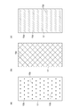
本発明は、上記実施形態に限られるものではない。例えば上記実施形態では、RGBの各色の波長に対応したレーザ光を出射する複数の光源を例示しているが、光源の数は適宜選択可能である。また、上記実施形態では、光非透過部15aがランダムなパターンで配置された光透過部材15を例示しているが、光非透過部のパターンは、パターン変調用駆動ミラー16でレーザ光が走査されたときにレーザ光の透過領域に対して変化するものであれば他の形態であってもよい。光非透過部の他のパターンとしては、例えば図4(a)に示すように、略円形の光非透過部15bが等間隔で配置されたものであってもよく、図4(b)に示すように、格子状をなす光非透過部15cであってもよい。また、図4(c)に示すように、斜線状をなす光非透過部15dを複数列にわたって配置したものであってもよい。
The present invention is not limited to the above embodiment. For example, in the above-described embodiment, a plurality of light sources that emit laser light corresponding to the wavelengths of RGB colors are illustrated, but the number of light sources can be selected as appropriate. In the above embodiment, the light transmitting member 15 in which the light non-transmitting portions 15a are arranged in a random pattern is illustrated. However, the pattern of the light non-transmitting portions is scanned by the laser beam by the pattern modulation drive mirror 16. Any other form may be used as long as it changes with respect to the laser light transmission region. As another pattern of the light non-transmissive portion, for example, as shown in FIG. 4A, substantially circular light non-transmissive portions 15b may be arranged at equal intervals. As shown, it may be a light non-transmissive portion 15c having a lattice shape. Moreover, as shown in FIG.4 (c), the light non-transmission part 15d which makes the oblique line shape may be arrange | positioned over several rows.
1…光源装置、2(2a,2b,2c)…光源、3…集光レンズ(第2の集光レンズ)、4…光走査装置、11…コリメートレンズ(第1のコリメートレンズ)、12…信号走査用駆動ミラー、13…コリメートレンズ(第2のコリメートレンズ)、14…集光レンズ(第1の集光レンズ)、15…光透過部材、15a~15d…光非透過部、16…パターン変調用駆動ミラー、18…駆動部。
DESCRIPTION OF SYMBOLS 1 ... Light source device, 2 (2a, 2b, 2c) ... Light source, 3 ... Condensing lens (2nd condensing lens), 4 ... Optical scanning device, 11 ... Collimating lens (1st collimating lens), 12 ... Signal scanning drive mirror, 13 ... collimating lens (second collimating lens), 14 ... condensing lens (first condensing lens), 15 ... light transmitting member, 15a to 15d ... light non-transmitting portion, 16 ... pattern Modulation drive mirror, 18... Drive unit.
Claims (5)
- 投影用信号で変調されたレーザ光を平行光化する第1のコリメートレンズと、
前記第1のコリメートレンズによって平行光化された前記レーザ光を対象物に向けて走査する信号走査用駆動ミラーと、を備え、
前記第1のコリメートレンズの前段には、光非透過部が所定のパターンで配置された光透過部材と、前記レーザ光を前記光透過部材に向けて走査するパターン変調用駆動ミラーとが配置されていることを特徴とする光走査装置。 A first collimating lens that collimates the laser light modulated by the projection signal;
A signal scanning drive mirror that scans the laser beam collimated by the first collimating lens toward an object;
In front of the first collimating lens, a light transmitting member in which a light non-transmitting portion is arranged in a predetermined pattern, and a pattern modulation driving mirror for scanning the laser light toward the light transmitting member are arranged. An optical scanning device characterized by comprising: - 前記信号走査用駆動ミラー及び前記パターン変調用駆動ミラーは、MEMSミラーであり、
前記パターン変調用駆動ミラーの駆動周波数が、前記信号走査用駆動ミラーの駆動周波数よりも大きいことを特徴とする請求項1記載の光走査装置。 The signal scanning drive mirror and the pattern modulation drive mirror are MEMS mirrors,
2. The optical scanning device according to claim 1, wherein a driving frequency of the pattern modulation driving mirror is higher than a driving frequency of the signal scanning driving mirror. - 前記光透過部材を前記レーザ光の光軸に交差する方向に駆動する駆動部を更に備えたことを特徴とする請求項1又は2記載の光走査装置。 3. The optical scanning device according to claim 1, further comprising a drive unit that drives the light transmitting member in a direction intersecting an optical axis of the laser light.
- 前記パターン変調用駆動ミラーと前記光透過部材との間には、前記パターン変調用駆動ミラーで反射した前記レーザ光を平行光化する第2のコリメートレンズが配置され、
前記光透過部材の後段には、前記光透過部材を透過した前記レーザ光を前記第1のコリメートレンズに向けて集光する第1の集光レンズが配置されていることを特徴とする請求項1~3のいずれか一項記載の光走査装置。 Between the pattern modulation drive mirror and the light transmission member, a second collimating lens for collimating the laser light reflected by the pattern modulation drive mirror is disposed,
The first condenser lens for condensing the laser light transmitted through the light transmissive member toward the first collimator lens is disposed at a subsequent stage of the light transmissive member. The optical scanning device according to any one of claims 1 to 3. - 請求項1~4のいずれか一項記載の光走査装置と、
前記レーザ光を出射する複数の光源と、
前記光源から出射した光を前記パターン変調用駆動ミラーに向けて集光する第2の集光レンズと、を備えたことを特徴とする光源装置。 An optical scanning device according to any one of claims 1 to 4,
A plurality of light sources for emitting the laser light;
And a second condenser lens for condensing the light emitted from the light source toward the pattern modulation drive mirror.
Applications Claiming Priority (2)
| Application Number | Priority Date | Filing Date | Title |
|---|---|---|---|
| JP2012-235007 | 2012-10-24 | ||
| JP2012235007A JP2014085548A (en) | 2012-10-24 | 2012-10-24 | Optical scanning device and light source device |
Publications (1)
| Publication Number | Publication Date |
|---|---|
| WO2014064964A1 true WO2014064964A1 (en) | 2014-05-01 |
Family
ID=50544345
Family Applications (1)
| Application Number | Title | Priority Date | Filing Date |
|---|---|---|---|
| PCT/JP2013/067208 WO2014064964A1 (en) | 2012-10-24 | 2013-06-24 | Optical scanning device and light source device |
Country Status (2)
| Country | Link |
|---|---|
| JP (1) | JP2014085548A (en) |
| WO (1) | WO2014064964A1 (en) |
Cited By (46)
| Publication number | Priority date | Publication date | Assignee | Title |
|---|---|---|---|---|
| CN106226984A (en) * | 2016-09-07 | 2016-12-14 | 海信集团有限公司 | A kind of LASER Light Source, laser projection device |
| US9622861B2 (en) | 2009-12-02 | 2017-04-18 | Valtech Cardio, Ltd. | Tool for actuating an adjusting mechanism |
| US9724192B2 (en) | 2011-11-08 | 2017-08-08 | Valtech Cardio, Ltd. | Controlled steering functionality for implant-delivery tool |
| US9730793B2 (en) | 2012-12-06 | 2017-08-15 | Valtech Cardio, Ltd. | Techniques for guide-wire based advancement of a tool |
| US9775709B2 (en) | 2011-11-04 | 2017-10-03 | Valtech Cardio, Ltd. | Implant having multiple adjustable mechanisms |
| US9872769B2 (en) | 2006-12-05 | 2018-01-23 | Valtech Cardio, Ltd. | Implantation of repair devices in the heart |
| US9883943B2 (en) | 2006-12-05 | 2018-02-06 | Valtech Cardio, Ltd. | Implantation of repair devices in the heart |
| US9937042B2 (en) | 2009-05-07 | 2018-04-10 | Valtech Cardio, Ltd. | Multiple anchor delivery tool |
| US9968452B2 (en) | 2009-05-04 | 2018-05-15 | Valtech Cardio, Ltd. | Annuloplasty ring delivery cathethers |
| US9968454B2 (en) | 2009-10-29 | 2018-05-15 | Valtech Cardio, Ltd. | Techniques for guide-wire based advancement of artificial chordae |
| US10098737B2 (en) | 2009-10-29 | 2018-10-16 | Valtech Cardio, Ltd. | Tissue anchor for annuloplasty device |
| US10195030B2 (en) | 2014-10-14 | 2019-02-05 | Valtech Cardio, Ltd. | Leaflet-restraining techniques |
| US10226342B2 (en) | 2016-07-08 | 2019-03-12 | Valtech Cardio, Ltd. | Adjustable annuloplasty device with alternating peaks and troughs |
| CN109477961A (en) * | 2016-07-19 | 2019-03-15 | 麦克赛尔株式会社 | Projection type video display apparatus |
| US10265170B2 (en) | 2013-12-26 | 2019-04-23 | Valtech Cardio, Ltd. | Implantation of flexible implant |
| US10299793B2 (en) | 2013-10-23 | 2019-05-28 | Valtech Cardio, Ltd. | Anchor magazine |
| US10350068B2 (en) | 2009-02-17 | 2019-07-16 | Valtech Cardio, Ltd. | Actively-engageable movement-restriction mechanism for use with an annuloplasty structure |
| US10470882B2 (en) | 2008-12-22 | 2019-11-12 | Valtech Cardio, Ltd. | Closure element for use with annuloplasty structure |
| US10517719B2 (en) | 2008-12-22 | 2019-12-31 | Valtech Cardio, Ltd. | Implantation of repair devices in the heart |
| US10548729B2 (en) | 2009-05-04 | 2020-02-04 | Valtech Cardio, Ltd. | Deployment techniques for annuloplasty ring and over-wire rotation tool |
| US10561498B2 (en) | 2005-03-17 | 2020-02-18 | Valtech Cardio, Ltd. | Mitral valve treatment techniques |
| US10682232B2 (en) | 2013-03-15 | 2020-06-16 | Edwards Lifesciences Corporation | Translation catheters, systems, and methods of use thereof |
| US10695046B2 (en) | 2005-07-05 | 2020-06-30 | Edwards Lifesciences Corporation | Tissue anchor and anchoring system |
| US10702274B2 (en) | 2016-05-26 | 2020-07-07 | Edwards Lifesciences Corporation | Method and system for closing left atrial appendage |
| US10751182B2 (en) | 2015-12-30 | 2020-08-25 | Edwards Lifesciences Corporation | System and method for reshaping right heart |
| US10765514B2 (en) | 2015-04-30 | 2020-09-08 | Valtech Cardio, Ltd. | Annuloplasty technologies |
| US10792152B2 (en) | 2011-06-23 | 2020-10-06 | Valtech Cardio, Ltd. | Closed band for percutaneous annuloplasty |
| US10828160B2 (en) | 2015-12-30 | 2020-11-10 | Edwards Lifesciences Corporation | System and method for reducing tricuspid regurgitation |
| US10835221B2 (en) | 2017-11-02 | 2020-11-17 | Valtech Cardio, Ltd. | Implant-cinching devices and systems |
| US10856986B2 (en) | 2008-12-22 | 2020-12-08 | Valtech Cardio, Ltd. | Adjustable annuloplasty devices and adjustment mechanisms therefor |
| US10893939B2 (en) | 2012-10-23 | 2021-01-19 | Valtech Cardio, Ltd. | Controlled steering functionality for implant delivery tool |
| US10918374B2 (en) | 2013-02-26 | 2021-02-16 | Edwards Lifesciences Corporation | Devices and methods for percutaneous tricuspid valve repair |
| US10918373B2 (en) | 2013-08-31 | 2021-02-16 | Edwards Lifesciences Corporation | Devices and methods for locating and implanting tissue anchors at mitral valve commissure |
| US10925610B2 (en) | 2015-03-05 | 2021-02-23 | Edwards Lifesciences Corporation | Devices for treating paravalvular leakage and methods use thereof |
| US11045627B2 (en) | 2017-04-18 | 2021-06-29 | Edwards Lifesciences Corporation | Catheter system with linear actuation control mechanism |
| US11123191B2 (en) | 2018-07-12 | 2021-09-21 | Valtech Cardio Ltd. | Annuloplasty systems and locking tools therefor |
| US11135062B2 (en) | 2017-11-20 | 2021-10-05 | Valtech Cardio Ltd. | Cinching of dilated heart muscle |
| US11259924B2 (en) | 2006-12-05 | 2022-03-01 | Valtech Cardio Ltd. | Implantation of repair devices in the heart |
| US11344310B2 (en) | 2012-10-23 | 2022-05-31 | Valtech Cardio Ltd. | Percutaneous tissue anchor techniques |
| US11395648B2 (en) | 2012-09-29 | 2022-07-26 | Edwards Lifesciences Corporation | Plication lock delivery system and method of use thereof |
| US11534583B2 (en) | 2013-03-14 | 2022-12-27 | Valtech Cardio Ltd. | Guidewire feeder |
| US11660191B2 (en) | 2008-03-10 | 2023-05-30 | Edwards Lifesciences Corporation | Method to reduce mitral regurgitation |
| US11660190B2 (en) | 2007-03-13 | 2023-05-30 | Edwards Lifesciences Corporation | Tissue anchors, systems and methods, and devices |
| US11666442B2 (en) | 2018-01-26 | 2023-06-06 | Edwards Lifesciences Innovation (Israel) Ltd. | Techniques for facilitating heart valve tethering and chord replacement |
| US11779463B2 (en) | 2018-01-24 | 2023-10-10 | Edwards Lifesciences Innovation (Israel) Ltd. | Contraction of an annuloplasty structure |
| US11819411B2 (en) | 2019-10-29 | 2023-11-21 | Edwards Lifesciences Innovation (Israel) Ltd. | Annuloplasty and tissue anchor technologies |
Citations (4)
| Publication number | Priority date | Publication date | Assignee | Title |
|---|---|---|---|---|
| JP2008152116A (en) * | 2006-12-19 | 2008-07-03 | Lasertec Corp | Lighting device and method |
| JP2009251004A (en) * | 2008-04-01 | 2009-10-29 | Seiko Epson Corp | Image display apparatus |
| JP2010151870A (en) * | 2008-12-24 | 2010-07-08 | Seiko Epson Corp | Scanning image display device |
| JP2012247744A (en) * | 2011-05-31 | 2012-12-13 | Hitachi Media Electoronics Co Ltd | Scanning display device |
-
2012
- 2012-10-24 JP JP2012235007A patent/JP2014085548A/en active Pending
-
2013
- 2013-06-24 WO PCT/JP2013/067208 patent/WO2014064964A1/en active Application Filing
Patent Citations (4)
| Publication number | Priority date | Publication date | Assignee | Title |
|---|---|---|---|---|
| JP2008152116A (en) * | 2006-12-19 | 2008-07-03 | Lasertec Corp | Lighting device and method |
| JP2009251004A (en) * | 2008-04-01 | 2009-10-29 | Seiko Epson Corp | Image display apparatus |
| JP2010151870A (en) * | 2008-12-24 | 2010-07-08 | Seiko Epson Corp | Scanning image display device |
| JP2012247744A (en) * | 2011-05-31 | 2012-12-13 | Hitachi Media Electoronics Co Ltd | Scanning display device |
Cited By (86)
| Publication number | Priority date | Publication date | Assignee | Title |
|---|---|---|---|---|
| US11497605B2 (en) | 2005-03-17 | 2022-11-15 | Valtech Cardio Ltd. | Mitral valve treatment techniques |
| US10561498B2 (en) | 2005-03-17 | 2020-02-18 | Valtech Cardio, Ltd. | Mitral valve treatment techniques |
| US10695046B2 (en) | 2005-07-05 | 2020-06-30 | Edwards Lifesciences Corporation | Tissue anchor and anchoring system |
| US11259924B2 (en) | 2006-12-05 | 2022-03-01 | Valtech Cardio Ltd. | Implantation of repair devices in the heart |
| US11344414B2 (en) | 2006-12-05 | 2022-05-31 | Valtech Cardio Ltd. | Implantation of repair devices in the heart |
| US9872769B2 (en) | 2006-12-05 | 2018-01-23 | Valtech Cardio, Ltd. | Implantation of repair devices in the heart |
| US9883943B2 (en) | 2006-12-05 | 2018-02-06 | Valtech Cardio, Ltd. | Implantation of repair devices in the heart |
| US10363137B2 (en) | 2006-12-05 | 2019-07-30 | Valtech Cardio, Ltd. | Implantation of repair devices in the heart |
| US10357366B2 (en) | 2006-12-05 | 2019-07-23 | Valtech Cardio, Ltd. | Implantation of repair devices in the heart |
| US9974653B2 (en) | 2006-12-05 | 2018-05-22 | Valtech Cardio, Ltd. | Implantation of repair devices in the heart |
| US11660190B2 (en) | 2007-03-13 | 2023-05-30 | Edwards Lifesciences Corporation | Tissue anchors, systems and methods, and devices |
| US11660191B2 (en) | 2008-03-10 | 2023-05-30 | Edwards Lifesciences Corporation | Method to reduce mitral regurgitation |
| US10517719B2 (en) | 2008-12-22 | 2019-12-31 | Valtech Cardio, Ltd. | Implantation of repair devices in the heart |
| US10470882B2 (en) | 2008-12-22 | 2019-11-12 | Valtech Cardio, Ltd. | Closure element for use with annuloplasty structure |
| US11116634B2 (en) | 2008-12-22 | 2021-09-14 | Valtech Cardio Ltd. | Annuloplasty implants |
| US10856986B2 (en) | 2008-12-22 | 2020-12-08 | Valtech Cardio, Ltd. | Adjustable annuloplasty devices and adjustment mechanisms therefor |
| US11202709B2 (en) | 2009-02-17 | 2021-12-21 | Valtech Cardio Ltd. | Actively-engageable movement-restriction mechanism for use with an annuloplasty structure |
| US10350068B2 (en) | 2009-02-17 | 2019-07-16 | Valtech Cardio, Ltd. | Actively-engageable movement-restriction mechanism for use with an annuloplasty structure |
| US11766327B2 (en) | 2009-05-04 | 2023-09-26 | Edwards Lifesciences Innovation (Israel) Ltd. | Implantation of repair chords in the heart |
| US10548729B2 (en) | 2009-05-04 | 2020-02-04 | Valtech Cardio, Ltd. | Deployment techniques for annuloplasty ring and over-wire rotation tool |
| US11844665B2 (en) | 2009-05-04 | 2023-12-19 | Edwards Lifesciences Innovation (Israel) Ltd. | Deployment techniques for annuloplasty structure |
| US11076958B2 (en) | 2009-05-04 | 2021-08-03 | Valtech Cardio, Ltd. | Annuloplasty ring delivery catheters |
| US11185412B2 (en) | 2009-05-04 | 2021-11-30 | Valtech Cardio Ltd. | Deployment techniques for annuloplasty implants |
| US9968452B2 (en) | 2009-05-04 | 2018-05-15 | Valtech Cardio, Ltd. | Annuloplasty ring delivery cathethers |
| US10856987B2 (en) | 2009-05-07 | 2020-12-08 | Valtech Cardio, Ltd. | Multiple anchor delivery tool |
| US11723774B2 (en) | 2009-05-07 | 2023-08-15 | Edwards Lifesciences Innovation (Israel) Ltd. | Multiple anchor delivery tool |
| US9937042B2 (en) | 2009-05-07 | 2018-04-10 | Valtech Cardio, Ltd. | Multiple anchor delivery tool |
| US9968454B2 (en) | 2009-10-29 | 2018-05-15 | Valtech Cardio, Ltd. | Techniques for guide-wire based advancement of artificial chordae |
| US11141271B2 (en) | 2009-10-29 | 2021-10-12 | Valtech Cardio Ltd. | Tissue anchor for annuloplasty device |
| US11617652B2 (en) | 2009-10-29 | 2023-04-04 | Edwards Lifesciences Innovation (Israel) Ltd. | Apparatus and method for guide-wire based advancement of an adjustable implant |
| US10751184B2 (en) | 2009-10-29 | 2020-08-25 | Valtech Cardio, Ltd. | Apparatus and method for guide-wire based advancement of an adjustable implant |
| US10098737B2 (en) | 2009-10-29 | 2018-10-16 | Valtech Cardio, Ltd. | Tissue anchor for annuloplasty device |
| US11602434B2 (en) | 2009-12-02 | 2023-03-14 | Edwards Lifesciences Innovation (Israel) Ltd. | Systems and methods for tissue adjustment |
| US9622861B2 (en) | 2009-12-02 | 2017-04-18 | Valtech Cardio, Ltd. | Tool for actuating an adjusting mechanism |
| US10492909B2 (en) | 2009-12-02 | 2019-12-03 | Valtech Cardio, Ltd. | Tool for actuating an adjusting mechanism |
| US10792152B2 (en) | 2011-06-23 | 2020-10-06 | Valtech Cardio, Ltd. | Closed band for percutaneous annuloplasty |
| US10363136B2 (en) | 2011-11-04 | 2019-07-30 | Valtech Cardio, Ltd. | Implant having multiple adjustment mechanisms |
| US11197759B2 (en) | 2011-11-04 | 2021-12-14 | Valtech Cardio Ltd. | Implant having multiple adjusting mechanisms |
| US9775709B2 (en) | 2011-11-04 | 2017-10-03 | Valtech Cardio, Ltd. | Implant having multiple adjustable mechanisms |
| US11857415B2 (en) | 2011-11-08 | 2024-01-02 | Edwards Lifesciences Innovation (Israel) Ltd. | Controlled steering functionality for implant-delivery tool |
| US10568738B2 (en) | 2011-11-08 | 2020-02-25 | Valtech Cardio, Ltd. | Controlled steering functionality for implant-delivery tool |
| US9724192B2 (en) | 2011-11-08 | 2017-08-08 | Valtech Cardio, Ltd. | Controlled steering functionality for implant-delivery tool |
| US11395648B2 (en) | 2012-09-29 | 2022-07-26 | Edwards Lifesciences Corporation | Plication lock delivery system and method of use thereof |
| US11890190B2 (en) | 2012-10-23 | 2024-02-06 | Edwards Lifesciences Innovation (Israel) Ltd. | Location indication system for implant-delivery tool |
| US11344310B2 (en) | 2012-10-23 | 2022-05-31 | Valtech Cardio Ltd. | Percutaneous tissue anchor techniques |
| US10893939B2 (en) | 2012-10-23 | 2021-01-19 | Valtech Cardio, Ltd. | Controlled steering functionality for implant delivery tool |
| US10610360B2 (en) | 2012-12-06 | 2020-04-07 | Valtech Cardio, Ltd. | Techniques for guide-wire based advancement of a tool |
| US9730793B2 (en) | 2012-12-06 | 2017-08-15 | Valtech Cardio, Ltd. | Techniques for guide-wire based advancement of a tool |
| US11583400B2 (en) | 2012-12-06 | 2023-02-21 | Edwards Lifesciences Innovation (Israel) Ltd. | Techniques for guided advancement of a tool |
| US11793505B2 (en) | 2013-02-26 | 2023-10-24 | Edwards Lifesciences Corporation | Devices and methods for percutaneous tricuspid valve repair |
| US10918374B2 (en) | 2013-02-26 | 2021-02-16 | Edwards Lifesciences Corporation | Devices and methods for percutaneous tricuspid valve repair |
| US11534583B2 (en) | 2013-03-14 | 2022-12-27 | Valtech Cardio Ltd. | Guidewire feeder |
| US10682232B2 (en) | 2013-03-15 | 2020-06-16 | Edwards Lifesciences Corporation | Translation catheters, systems, and methods of use thereof |
| US11890194B2 (en) | 2013-03-15 | 2024-02-06 | Edwards Lifesciences Corporation | Translation catheters, systems, and methods of use thereof |
| US10918373B2 (en) | 2013-08-31 | 2021-02-16 | Edwards Lifesciences Corporation | Devices and methods for locating and implanting tissue anchors at mitral valve commissure |
| US11744573B2 (en) | 2013-08-31 | 2023-09-05 | Edwards Lifesciences Corporation | Devices and methods for locating and implanting tissue anchors at mitral valve commissure |
| US11065001B2 (en) | 2013-10-23 | 2021-07-20 | Valtech Cardio, Ltd. | Anchor magazine |
| US10299793B2 (en) | 2013-10-23 | 2019-05-28 | Valtech Cardio, Ltd. | Anchor magazine |
| US11766263B2 (en) | 2013-10-23 | 2023-09-26 | Edwards Lifesciences Innovation (Israel) Ltd. | Anchor magazine |
| US10265170B2 (en) | 2013-12-26 | 2019-04-23 | Valtech Cardio, Ltd. | Implantation of flexible implant |
| US10973637B2 (en) | 2013-12-26 | 2021-04-13 | Valtech Cardio, Ltd. | Implantation of flexible implant |
| US11071628B2 (en) | 2014-10-14 | 2021-07-27 | Valtech Cardio, Ltd. | Leaflet-restraining techniques |
| US10195030B2 (en) | 2014-10-14 | 2019-02-05 | Valtech Cardio, Ltd. | Leaflet-restraining techniques |
| US10925610B2 (en) | 2015-03-05 | 2021-02-23 | Edwards Lifesciences Corporation | Devices for treating paravalvular leakage and methods use thereof |
| US11020227B2 (en) | 2015-04-30 | 2021-06-01 | Valtech Cardio, Ltd. | Annuloplasty technologies |
| US10765514B2 (en) | 2015-04-30 | 2020-09-08 | Valtech Cardio, Ltd. | Annuloplasty technologies |
| US10828160B2 (en) | 2015-12-30 | 2020-11-10 | Edwards Lifesciences Corporation | System and method for reducing tricuspid regurgitation |
| US10751182B2 (en) | 2015-12-30 | 2020-08-25 | Edwards Lifesciences Corporation | System and method for reshaping right heart |
| US11660192B2 (en) | 2015-12-30 | 2023-05-30 | Edwards Lifesciences Corporation | System and method for reshaping heart |
| US11890193B2 (en) | 2015-12-30 | 2024-02-06 | Edwards Lifesciences Corporation | System and method for reducing tricuspid regurgitation |
| US10702274B2 (en) | 2016-05-26 | 2020-07-07 | Edwards Lifesciences Corporation | Method and system for closing left atrial appendage |
| US11540835B2 (en) | 2016-05-26 | 2023-01-03 | Edwards Lifesciences Corporation | Method and system for closing left atrial appendage |
| US10959845B2 (en) | 2016-07-08 | 2021-03-30 | Valtech Cardio, Ltd. | Adjustable annuloplasty device with alternating peaks and troughs |
| US10226342B2 (en) | 2016-07-08 | 2019-03-12 | Valtech Cardio, Ltd. | Adjustable annuloplasty device with alternating peaks and troughs |
| CN109477961A (en) * | 2016-07-19 | 2019-03-15 | 麦克赛尔株式会社 | Projection type video display apparatus |
| CN106226984A (en) * | 2016-09-07 | 2016-12-14 | 海信集团有限公司 | A kind of LASER Light Source, laser projection device |
| US11883611B2 (en) | 2017-04-18 | 2024-01-30 | Edwards Lifesciences Corporation | Catheter system with linear actuation control mechanism |
| US11045627B2 (en) | 2017-04-18 | 2021-06-29 | Edwards Lifesciences Corporation | Catheter system with linear actuation control mechanism |
| US11832784B2 (en) | 2017-11-02 | 2023-12-05 | Edwards Lifesciences Innovation (Israel) Ltd. | Implant-cinching devices and systems |
| US10835221B2 (en) | 2017-11-02 | 2020-11-17 | Valtech Cardio, Ltd. | Implant-cinching devices and systems |
| US11135062B2 (en) | 2017-11-20 | 2021-10-05 | Valtech Cardio Ltd. | Cinching of dilated heart muscle |
| US11779463B2 (en) | 2018-01-24 | 2023-10-10 | Edwards Lifesciences Innovation (Israel) Ltd. | Contraction of an annuloplasty structure |
| US11666442B2 (en) | 2018-01-26 | 2023-06-06 | Edwards Lifesciences Innovation (Israel) Ltd. | Techniques for facilitating heart valve tethering and chord replacement |
| US11890191B2 (en) | 2018-07-12 | 2024-02-06 | Edwards Lifesciences Innovation (Israel) Ltd. | Fastener and techniques therefor |
| US11123191B2 (en) | 2018-07-12 | 2021-09-21 | Valtech Cardio Ltd. | Annuloplasty systems and locking tools therefor |
| US11819411B2 (en) | 2019-10-29 | 2023-11-21 | Edwards Lifesciences Innovation (Israel) Ltd. | Annuloplasty and tissue anchor technologies |
Also Published As
| Publication number | Publication date |
|---|---|
| JP2014085548A (en) | 2014-05-12 |
Similar Documents
| Publication | Publication Date | Title |
|---|---|---|
| WO2014064964A1 (en) | Optical scanning device and light source device | |
| US7484340B2 (en) | Displaying optical system and image projection apparatus | |
| JP5682813B2 (en) | Lighting device and projector | |
| JP5724949B2 (en) | Head-up display device | |
| US7997737B2 (en) | Projection display device, and speckle reduction element | |
| JP4290095B2 (en) | Display optical system and image display system | |
| WO2015102063A1 (en) | Transmissive screen and image display device using same | |
| US9013641B2 (en) | Projection type image display device | |
| JP5949714B2 (en) | Head-up display device | |
| JP5900445B2 (en) | Head-up display device | |
| WO2011046034A1 (en) | Image projection device, image projection method and image display device | |
| JP2010026483A (en) | Projection display apparatus for suppressing speckle noise | |
| JP4818435B2 (en) | Laser back irradiation device and liquid crystal display device | |
| US9618767B2 (en) | Projector | |
| JP2012145804A (en) | Projector | |
| CN106662800B (en) | Grenade instrumentation and lighting device | |
| JP2010152066A (en) | Image display device and light source apparatus | |
| JP5991389B2 (en) | Lighting device and projector | |
| JP6311971B2 (en) | Illumination device, projection device and irradiation device | |
| WO2009133111A1 (en) | Optical system for speckle reduction | |
| JP2012247744A (en) | Scanning display device | |
| JP2011215194A (en) | Direct viewing type image display device | |
| US7443567B2 (en) | Image enhancement of a microdisplay through acoustooptics | |
| JP2016184064A (en) | Despeckle illumination device, despeckle illumination method, and projection type display device | |
| JP2008158190A (en) | Illuminating device and projector |
Legal Events
| Date | Code | Title | Description |
|---|---|---|---|
| 121 | Ep: the epo has been informed by wipo that ep was designated in this application |
Ref document number: 13848376 Country of ref document: EP Kind code of ref document: A1 |
|
| NENP | Non-entry into the national phase |
Ref country code: DE |
|
| 122 | Ep: pct application non-entry in european phase |
Ref document number: 13848376 Country of ref document: EP Kind code of ref document: A1 |