WO2014162499A1 - Implant assembly - Google Patents
Implant assembly Download PDFInfo
- Publication number
- WO2014162499A1 WO2014162499A1 PCT/JP2013/060025 JP2013060025W WO2014162499A1 WO 2014162499 A1 WO2014162499 A1 WO 2014162499A1 JP 2013060025 W JP2013060025 W JP 2013060025W WO 2014162499 A1 WO2014162499 A1 WO 2014162499A1
- Authority
- WO
- WIPO (PCT)
- Prior art keywords
- implant
- guide means
- living body
- friction
- filler
- Prior art date
Links
- 0 C1C**CC1 Chemical compound C1C**CC1 0.000 description 2
Images


Classifications
-
- A—HUMAN NECESSITIES
- A61—MEDICAL OR VETERINARY SCIENCE; HYGIENE
- A61F—FILTERS IMPLANTABLE INTO BLOOD VESSELS; PROSTHESES; DEVICES PROVIDING PATENCY TO, OR PREVENTING COLLAPSING OF, TUBULAR STRUCTURES OF THE BODY, e.g. STENTS; ORTHOPAEDIC, NURSING OR CONTRACEPTIVE DEVICES; FOMENTATION; TREATMENT OR PROTECTION OF EYES OR EARS; BANDAGES, DRESSINGS OR ABSORBENT PADS; FIRST-AID KITS
- A61F2/00—Filters implantable into blood vessels; Prostheses, i.e. artificial substitutes or replacements for parts of the body; Appliances for connecting them with the body; Devices providing patency to, or preventing collapsing of, tubular structures of the body, e.g. stents
- A61F2/02—Prostheses implantable into the body
- A61F2/30—Joints
- A61F2/44—Joints for the spine, e.g. vertebrae, spinal discs
- A61F2/441—Joints for the spine, e.g. vertebrae, spinal discs made of inflatable pockets or chambers filled with fluid, e.g. with hydrogel
-
- A—HUMAN NECESSITIES
- A61—MEDICAL OR VETERINARY SCIENCE; HYGIENE
- A61B—DIAGNOSIS; SURGERY; IDENTIFICATION
- A61B17/00—Surgical instruments, devices or methods, e.g. tourniquets
- A61B17/56—Surgical instruments or methods for treatment of bones or joints; Devices specially adapted therefor
- A61B17/58—Surgical instruments or methods for treatment of bones or joints; Devices specially adapted therefor for osteosynthesis, e.g. bone plates, screws, setting implements or the like
- A61B17/68—Internal fixation devices, including fasteners and spinal fixators, even if a part thereof projects from the skin
- A61B17/70—Spinal positioners or stabilisers ; Bone stabilisers comprising fluid filler in an implant
- A61B17/7062—Devices acting on, attached to, or simulating the effect of, vertebral processes, vertebral facets or ribs ; Tools for such devices
- A61B17/7065—Devices with changeable shape, e.g. collapsible or having retractable arms to aid implantation; Tools therefor
-
- A—HUMAN NECESSITIES
- A61—MEDICAL OR VETERINARY SCIENCE; HYGIENE
- A61F—FILTERS IMPLANTABLE INTO BLOOD VESSELS; PROSTHESES; DEVICES PROVIDING PATENCY TO, OR PREVENTING COLLAPSING OF, TUBULAR STRUCTURES OF THE BODY, e.g. STENTS; ORTHOPAEDIC, NURSING OR CONTRACEPTIVE DEVICES; FOMENTATION; TREATMENT OR PROTECTION OF EYES OR EARS; BANDAGES, DRESSINGS OR ABSORBENT PADS; FIRST-AID KITS
- A61F2/00—Filters implantable into blood vessels; Prostheses, i.e. artificial substitutes or replacements for parts of the body; Appliances for connecting them with the body; Devices providing patency to, or preventing collapsing of, tubular structures of the body, e.g. stents
- A61F2/02—Prostheses implantable into the body
- A61F2/30—Joints
- A61F2/44—Joints for the spine, e.g. vertebrae, spinal discs
- A61F2/4405—Joints for the spine, e.g. vertebrae, spinal discs for apophyseal or facet joints, i.e. between adjacent spinous or transverse processes
-
- A—HUMAN NECESSITIES
- A61—MEDICAL OR VETERINARY SCIENCE; HYGIENE
- A61F—FILTERS IMPLANTABLE INTO BLOOD VESSELS; PROSTHESES; DEVICES PROVIDING PATENCY TO, OR PREVENTING COLLAPSING OF, TUBULAR STRUCTURES OF THE BODY, e.g. STENTS; ORTHOPAEDIC, NURSING OR CONTRACEPTIVE DEVICES; FOMENTATION; TREATMENT OR PROTECTION OF EYES OR EARS; BANDAGES, DRESSINGS OR ABSORBENT PADS; FIRST-AID KITS
- A61F2/00—Filters implantable into blood vessels; Prostheses, i.e. artificial substitutes or replacements for parts of the body; Appliances for connecting them with the body; Devices providing patency to, or preventing collapsing of, tubular structures of the body, e.g. stents
- A61F2/02—Prostheses implantable into the body
- A61F2/30—Joints
- A61F2/46—Special tools or methods for implanting or extracting artificial joints, accessories, bone grafts or substitutes, or particular adaptations therefor
- A61F2/4603—Special tools or methods for implanting or extracting artificial joints, accessories, bone grafts or substitutes, or particular adaptations therefor for insertion or extraction of endoprosthetic joints or of accessories thereof
- A61F2/4611—Special tools or methods for implanting or extracting artificial joints, accessories, bone grafts or substitutes, or particular adaptations therefor for insertion or extraction of endoprosthetic joints or of accessories thereof of spinal prostheses
-
- A—HUMAN NECESSITIES
- A61—MEDICAL OR VETERINARY SCIENCE; HYGIENE
- A61F—FILTERS IMPLANTABLE INTO BLOOD VESSELS; PROSTHESES; DEVICES PROVIDING PATENCY TO, OR PREVENTING COLLAPSING OF, TUBULAR STRUCTURES OF THE BODY, e.g. STENTS; ORTHOPAEDIC, NURSING OR CONTRACEPTIVE DEVICES; FOMENTATION; TREATMENT OR PROTECTION OF EYES OR EARS; BANDAGES, DRESSINGS OR ABSORBENT PADS; FIRST-AID KITS
- A61F2/00—Filters implantable into blood vessels; Prostheses, i.e. artificial substitutes or replacements for parts of the body; Appliances for connecting them with the body; Devices providing patency to, or preventing collapsing of, tubular structures of the body, e.g. stents
- A61F2/02—Prostheses implantable into the body
- A61F2/30—Joints
- A61F2/46—Special tools or methods for implanting or extracting artificial joints, accessories, bone grafts or substitutes, or particular adaptations therefor
- A61F2/4603—Special tools or methods for implanting or extracting artificial joints, accessories, bone grafts or substitutes, or particular adaptations therefor for insertion or extraction of endoprosthetic joints or of accessories thereof
-
- A—HUMAN NECESSITIES
- A61—MEDICAL OR VETERINARY SCIENCE; HYGIENE
- A61F—FILTERS IMPLANTABLE INTO BLOOD VESSELS; PROSTHESES; DEVICES PROVIDING PATENCY TO, OR PREVENTING COLLAPSING OF, TUBULAR STRUCTURES OF THE BODY, e.g. STENTS; ORTHOPAEDIC, NURSING OR CONTRACEPTIVE DEVICES; FOMENTATION; TREATMENT OR PROTECTION OF EYES OR EARS; BANDAGES, DRESSINGS OR ABSORBENT PADS; FIRST-AID KITS
- A61F2/00—Filters implantable into blood vessels; Prostheses, i.e. artificial substitutes or replacements for parts of the body; Appliances for connecting them with the body; Devices providing patency to, or preventing collapsing of, tubular structures of the body, e.g. stents
- A61F2/02—Prostheses implantable into the body
- A61F2/30—Joints
- A61F2002/30001—Additional features of subject-matter classified in A61F2/28, A61F2/30 and subgroups thereof
- A61F2002/30108—Shapes
- A61F2002/3011—Cross-sections or two-dimensional shapes
- A61F2002/30112—Rounded shapes, e.g. with rounded corners
- A61F2002/3013—Rounded shapes, e.g. with rounded corners figure-"8"- or hourglass-shaped
-
- A—HUMAN NECESSITIES
- A61—MEDICAL OR VETERINARY SCIENCE; HYGIENE
- A61F—FILTERS IMPLANTABLE INTO BLOOD VESSELS; PROSTHESES; DEVICES PROVIDING PATENCY TO, OR PREVENTING COLLAPSING OF, TUBULAR STRUCTURES OF THE BODY, e.g. STENTS; ORTHOPAEDIC, NURSING OR CONTRACEPTIVE DEVICES; FOMENTATION; TREATMENT OR PROTECTION OF EYES OR EARS; BANDAGES, DRESSINGS OR ABSORBENT PADS; FIRST-AID KITS
- A61F2/00—Filters implantable into blood vessels; Prostheses, i.e. artificial substitutes or replacements for parts of the body; Appliances for connecting them with the body; Devices providing patency to, or preventing collapsing of, tubular structures of the body, e.g. stents
- A61F2/02—Prostheses implantable into the body
- A61F2/30—Joints
- A61F2002/30001—Additional features of subject-matter classified in A61F2/28, A61F2/30 and subgroups thereof
- A61F2002/30316—The prosthesis having different structural features at different locations within the same prosthesis; Connections between prosthetic parts; Special structural features of bone or joint prostheses not otherwise provided for
- A61F2002/30535—Special structural features of bone or joint prostheses not otherwise provided for
- A61F2002/30581—Special structural features of bone or joint prostheses not otherwise provided for having a pocket filled with fluid, e.g. liquid
- A61F2002/30583—Special structural features of bone or joint prostheses not otherwise provided for having a pocket filled with fluid, e.g. liquid filled with hardenable fluid, e.g. curable in-situ
Definitions
- the present invention relates to an implant assembly including an implant placed in a living body.
- Patent Document 1 discloses an invention of an implant that expands by introducing a filler.
- This implant is placed in the living body percutaneously in a folded state.
- the implant placed in the living body is filled with the filler and expanded from the end (base side) on the side where the filler is injected.
- the filler is injected into the implant in a state where the structure in the body is in contact with or interferes with the outer surface of the implant, the filler does not spread evenly in the implant and expands unevenly. There is. If the filling material is continuously injected into the non-uniformly expanding implant, a pressing force is applied to a portion in contact with or interfering with a structure in the body due to the injection pressure.
- Patent Document 2 discloses an invention of a balloon catheter that prevents the displacement of the balloon when the balloon is expanded by covering the surface of the folded balloon catheter with a highly adhesive substance from the beginning. ing.
- displacement of the implant from the indwelling position can be prevented by diverting a technique for coating such a surface with a highly adhesive substance from the beginning to the implant.
- the surface of the folded implant is covered with a highly sticky substance from the beginning, the sticky substance sticks, and it becomes difficult to expand the implant even if a filler is injected into the implant.
- the surface of the implant is covered with a highly adhesive substance from the beginning, the implant cannot be smoothly introduced into the living body.
- the present invention has been made to solve the above-described problems, and can be used to smoothly introduce a folded implant into a living body and to place the implant in a position when injecting a filler.
- An object of the present invention is to provide an implant assembly that can be smoothly expanded without being displaced from the position.
- Implant assembly comprising: an implant coated on a portion; and guide means for preventing the implant from contacting the body fluid in the living body and guiding the movement of the implant to the indwelling position in the living body .
- the implant includes a trunk portion extending in a longitudinal direction, and a wide portion provided at both ends of the trunk portion, and having a width in a direction intersecting the longitudinal direction larger than that of the trunk portion in a state after expansion.
- the guide means includes friction reducing means for reducing friction between a lumen through which the implant can be inserted and the implant provided on at least a part of an inner surface of the guide means formed by the lumen.
- the implant assembly according to any one of (1) to (3), comprising:
- the implant assembly has an implant and guide means.
- the implant is coated on at least a part of its surface with a coating material that increases the coefficient of friction by contact with the liquid. For this reason, since the coating material on the surface of the implant and the body fluid come into contact with each other in the living body and the friction coefficient is increased, the implant can be smoothly expanded without being displaced from the positioned indwelling position when the filler is injected. Can do.
- the guide means prevents the implant from contacting the body fluid in the living body and guides the movement of the implant to the indwelling position in the living body. For this reason, it can prevent that the friction coefficient of the coating
- the surface of the folded and contracted implant is covered with the first surface portion exposed to the outside, and the second surface portion is located inside the first surface portion. Since the covering material is only covered, it is possible to suitably prevent the covering material and the body fluid from coming into contact with each other when the body fluid enters the guide means during the movement to the indwelling position. For this reason, it can prevent that the friction coefficient of the coating
- the implant is provided at the body portion extending in the longitudinal direction and at both ends of the body portion, and in the expanded state, the width in the direction intersecting the longitudinal direction is larger than that of the body portion. And a wide portion. Since the implant has such a shape, since the covering material is provided in the wide part having the largest change amount and the largest contact area with the living body at least before and after the expansion deformation of the implant, the implant is injected when the filler is injected. Can be prevented from being displaced from the indwelling position where it is positioned.
- the inner surface of the guide means is formed in an uneven shape, the contact area between the implant and the guide means is reduced, and the implant can be smoothly introduced into the living body. Further, even when the body fluid enters the inner surface of the guide means, the body fluid can be retracted into the concave groove. For this reason, when the implant is moved to the indwelling position in the living body, it is possible to prevent the covering material on the surface of the implant and the body fluid from coming into contact with each other. Therefore, it is possible to prevent the friction coefficient of the coating material on the surface of the implant from being increased during the movement to the indwelling position, and thereby the implant can be smoothly introduced into the living body.
- the absorbent material capable of absorbing bodily fluid is provided in the concave groove formed on the inner surface of the guide means, the bodily fluid retreated in the groove is retained. be able to.
- covering material and body fluid of the surface of an implant contact it is possible to more reliably prevent an increase in the friction coefficient of the coating material on the surface of the implant during the movement to the indwelling position, and thereby the implant can be smoothly introduced into the living body.
- the friction reducing means is composed of the low friction material coated on the inner surface of the guide means, the friction between the implant and the guide means is more reliably reduced. The For this reason, it can prevent that the friction coefficient of the coating
- FIG. 2 is a cross-sectional view taken along line 2B-2B in FIG. It is the schematic for demonstrating the implant before the expansion deformation which concerns on 1st Embodiment of this invention. It is the schematic for demonstrating the implant after the expansion deformation which concerns on 1st Embodiment of this invention. It is a figure for demonstrating the puncture device used in order to introduce
- This embodiment exemplifies a form in which the present invention is applied as a medical instrument used for introducing an implant between adjacent spinous processes in a living body.
- the spinous process of the biological body in which the implant 20 is indwelled, and the disease used as a treatment target are demonstrated easily.
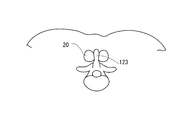
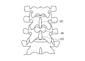
- FIG. 5A is a diagram schematically showing a perspective view of the spinous process from the back side of the living body
- FIG. 5B is an enlarged view of the peripheral portion of the spinous process of FIG. 5A
- FIG. It is a figure which shows typically the cross section (transverse section) of the biological body in the direction orthogonal to the arrangement direction (extension direction of a spine) of arium
- the X axis shown in each figure indicates the direction orthogonal to the arrangement direction of the spinous processes
- the Y axis shows the arrangement direction of the spinous processes
- the Z axis shows the thickness direction of the living body.
- a plurality of lumbar vertebrae 126 are arranged on the back 121 of the living body 120 along the extending direction of the spine (see FIG. 5B).
- the lumbar vertebra 126 has a configuration in which a front half vertebral body 125 and a latter half vertebral disc 127 are connected via a pedicle 128 (see FIGS. 5B and 5C).
- various processes such as spinous processes 123, lateral processes (radial processes), upper joint processes, lower joint processes, and the like are formed.
- the lumbar vertebra 126 is normally lightly bent toward the front side of the living body 120.
- Adjacent vertebral bodies 125 are connected via an intervertebral disc (intervertebral disc) 129, and a vertebral body and a vertebral body adjacent to the vertebral body are intervertebral disc 129, upper joint process, and lower joint process. (See FIG. 5B).
- intervertebral disc intervertebral disc
- lumbar sequestration in which the vertebral body 125 and the lamina 127 are separated at the pedicle 128 portion, Deformation of the intervertebral joints and degeneration of the intervertebral disc 129 may make it difficult to fix the lumbar vertebra 126 located on the upper side, and may cause lumbar degenerative slippage that causes a shift.
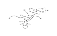
- lumbar spinal canal stenosis there is a treatment method for suppressing spinal canal stenosis by placing an implant 20 that can function as a spacer between adjacent spinous processes 123 (see FIGS. 8A and 8B). ).
- the implant assembly 10 is used for an indwelling procedure for indwelling the implant 20.
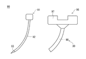
- the implant assembly 10 is expanded from a collapsed and contracted state by introducing a filler as shown in FIGS. 1, 3A, and 3B.
- the implant 20 is configured so as to be deformable and has a coating material m on which at least a part of the surface is coated with a coating material m whose friction coefficient is increased by contact with the body fluid, and the implant 20 and the body fluid of the living body contact each other in the living body.
- guide means 30 for guiding the movement of the implant 20 to the indwelling position in the living body.
- the implant assembly 10 is constituted by the implant 20 and the guide means 30.
- the implant 20 is introduced into the living body 120 in a folded and contracted state (see FIG. 7A). Further, after being positioned at the indwelling position in the vicinity of the spinous process 123, it is expanded and deformed by injecting a filler therein, and is indwelled in an expanded and deformed state (see FIG. 7B). At this time, since the coating material m on the surface of the implant 20 and the body fluid come into contact with each other in the living body 120 and the friction coefficient is increased, the implant 20 can be smoothly moved without being displaced from the indwelling position where the implant 20 is positioned. Can be extended. In this way, the implant 20 can be used to expand between bones, between cartilages, within cartilage, or within bones of a living body.
- a body part 21 extending in the longitudinal direction and a wide part 22 having a larger width than the body part 21 are formed.
- the body portion 21 is formed at the center portion of the implant 20, and wide portions 22 are formed at both ends of the implant 20 so as to sandwich the body portion 21 therebetween.
- the implant 20 after expansion deformation has a dumbbell (substantially H-shaped) outer shape.
- the interval between the adjacent spinous processes 123 is maintained in the trunk portion 21 of the implant 20. Further, the spinous processes 123 are sandwiched between the wide portions 22 located at both ends of the implant 20, thereby preventing the positional displacement of the implant 20 after placement.
- the shape of the implant 20 before and after expansion may be changed as long as it can function as a spacer that supports the bone in the living body by the expanded and deformed implant and maintains the distance between the bones. Is possible.
- the implant 20 after the expansion deformation has been described as having a dumbbell-shaped (substantially H-shaped) outer shape, but, for example, a straight shape having a constant shape without a wide portion, for example, gradually from the center to the end. It may be an hourglass shape that is wide in shape.
- the covering material m is described as a configuration in which at least a part of the surface of the implant 20 is covered, but a specific covering position of the covering material m will be described in detail below.
- the surface of the implant 20 in the folded and contracted state is exposed to the first surface portion 23 that is exposed to the outside, and is covered with the first surface portion 23 and inside the first surface portion 23.
- a second surface portion 24 is formed, and the covering material m is covered only by the second surface portion 24.
- the covering material m In the state where the implant 20 is folded and contracted, only the second surface portion 24 located inside the first surface portion 23 covered with the first surface portion 23 exposed to the outside is covered with the covering material m. ing. Therefore, even if the body fluid enters the guide means 30 while the implant 20 is moved to the indwelling position by the guide means 30, the covering material m is covered only on the second surface portion 24 covered by the first surface portion 23. So that it does not come into contact with body fluids. For this reason, the implant 20 can be smoothly introduced into the living body without inhibiting the introduction of the implant 20 into the living body.
- the covering material m covered only on the second surface portion 24 of the folded implant 20 is exposed on the surface of the implant 20 as shown in FIG. 3B. .
- the covering material m exposed on the surface of the implant 20 comes into contact with the body fluid and increases the coefficient of friction.
- Examples of the base material for the implant 20 include a polyester resin base material, a polyamide resin base material, a polyolefin resin base material, a polyimide resin base material, an ethylene / vinyl alcohol copolymer base material, and a polyvinyl chloride resin base material.
- Surfaces such as plastic substrates, combinations of these, matte treatment, corona discharge treatment, plasma treatment, ultraviolet irradiation treatment, electron beam irradiation treatment, flame plasma treatment and ozone treatment, or various easy adhesion treatments. It can select and use from well-known things, such as what processed.
- the expansion of the implant 20 can be performed by filling the inside of the implant 20 with various fillers such as a solid or a fluid (gas, liquid, gel), and the material of the filler is not particularly limited.
- a filler a solid or a hardener that is cured after introduction with a fluid when introduced into the implant 20 (hereinafter also simply referred to as “hardener”). ) Is preferably used.
- the material of the covering material m for example, a natural product, a chemically modified natural product, a synthetic product, or a mixture of two or more of these is used.
- specific examples of the above materials include, for example, synthetic products such as polyvinyl alcohol, polyvinyl methyl ether, polyvinyl pyrrolidone, polyacrylamide, polyethylene oxide, polyacrylic acid-containing polymer, polycarboxylic acid-containing polymer, cationic resin, poly-N-vinyl- Synthetic products such as 2-pyrrolidone, styrene-maleic anhydride copolymer, ethylene-maleic anhydride copolymer, agar, starch, proteins, carrageenin, guar gum, gum arabic, tragacanth gum, locust bean gum, chemically modified natural
- the product include cationic starch, dextran, hydroxyalkyl starch, methylcellulose, sodium carboxymethylcellulose, xanthan gum, and dextrin.
- the coating material m can contain a compatible liquid plasticizer, filler, or both.
- a liquid plasticizer improves the flexibility of the wet pressure-sensitive adhesive and improves the absorbability of body fluids, water, and hydrophilic media, leading to rapid adhesion.
- the mechanical strength of the coating material can be improved.
- liquid plasticizer it is preferable to use alkylene glycol, polyalkylene glycol, glycerin, polyglycerin, or sorbitol, and these can be used in combination of two or more.
- the method for forming the coating material m can be selected from known methods such as a method of dipping the implant 20 in a solution in which the coating material m is dissolved or dispersed in a solvent, and a method of spraying the solution onto the surface of the implant 20.
- a solvent for example, an organic solvent such as alcohol, acetone, tetrahydrofuran, dimethyl sulfoxide, water or hexane is used.
- fillers include organic fillers such as polymethyl methacrylate, inorganic oxides such as silica, alumina, zinc oxide, titanium oxide, talc, clay, kaolin, and glass, inorganic composite oxides, barium sulfate, calcium carbonate,
- inorganic fillers such as calcium phosphate, hydroxyapatite, ceramics, carbon, and metal fillers (wire, coil shape, etc.) such as stainless steel, titanium, nickel / titanium alloy can be used.
- the hardener preferably has at least one of the following properties: (a) safe for the patient; (b) little or no tissue damage; (c) a temperature close to the patient's body temperature (about 35- (D) No shrinkage or expansion can be maintained and the cured shape can be maintained; (e) 1 to 60 minutes after injection, preferably 5 to 30 minutes, more preferably 10 minutes (F) As a solvent, water, buffer solution, physiological saline, contrast medium, or oils and fats such as olive oil and castor oil can be used.
- the curing material include: (g) two-component mixed crosslinked polymer; (h) hot melt adhesive; (i) urethane elastomer; (j) photocurable resin; (k) acrylic resin; ) Bone cement; (m) solutions that crystallize upon external stimulation.
- the two-component mixed crosslinked polymer may be a combination of an aromatic diepoxide resin or aliphatic diepoxide resin and an amine compound, or a polyorganosiloxane having a reactive group, a crosslinking agent, and a curing catalyst.
- the hot melt adhesive a combination of a material that can be cured by reacting with water and water, EVA (ethylene vinyl acetate copolymer) system, PO (polyolefin) system, PA (polyamide) system SR (synthetic rubber) system, ACR (acrylic) system, PUR (polyurethane / moisture curing type) system, and the like.
- EVA ethylene vinyl acetate copolymer
- PO polyolefin
- PA polyamide
- ACR acrylic
- PUR polyurethane / moisture curing type
- the urethane elastomer is preferably a polymer derived from a polyol and an aromatic polyisocyanate.
- examples of the photopolymerizable monomer include acrylic acid esters, methacrylic acid esters, and ethylenically unsaturated carboxylic acids.
- a polymerization accelerator, a crosslinking agent, a photopolymerization initiator, and the like may be used as necessary. it can.
- examples of the acrylic resin include methyl (meth) acrylate, (meth) Ethyl acrylate, butyl (meth) acrylate, n-hexyl (meth) acrylate, cyclohexyl (meth) acrylate, 2-ethylhexyl (meth) acrylate, n-octyl (meth) acrylate, (meth) Known methods for monomers such as nonyl acrylate, decyl (meth) acrylate, (meth) acrylic acid, glycidyl (meth) acrylate, vinyl acetate, styrene, ⁇ -methylstyrene, (meth) acrylamide, (meth) acrylonitrile And those polymerized in step (b).
- the bone cement is made of, for example, polymethylmethacrylate, methylmethacrylate-styrene copolymer, benzoyl peroxide, barium sulfate, etc. into methyl methacrylate, N, N-dimethyl-para-toluidine, hydroquinone, etc. It is produced by mixing the solvent.
- examples of the solution that crystallizes by external stimulation include aqueous solutions in which sodium acetate, sodium chloride, and the like are dissolved.
- examples of the external stimulus include physical impact, heat, light, electricity, and ultrasonic waves.
- the implant 20 When introduced as a filler, it functions as a spacer between the spinous processes 123 over a long period of time in a state where the implant 20 is expanded and deformed in the same manner as in the case of using a solid as the filler by using a hardening material that hardens after introduction with a fluid. Can be made.
- the implant 20 is provided with one introduction port 60.
- the introduction port 60 is provided at a proximal portion in the introduction direction to the living body.
- the introduction port 60 can be used to fill the interior of the implant 20 with a filler.
- the tubular member 83 used for feeding the filler into the implant 20 through the introduction port 60 has a configuration that is detachable from the introduction port 60. With such a configuration, the tubular member 83 is detachable from the implant 20. Further, the introduction port 60 has a seal portion (not shown), and the seal portion can maintain a liquid-tight / air-tight state between the implant 20 and the tubular member 83. Examples of the other inlet 60 include a detachable luer lock-shaped joint, and a male / female threaded joint that can be detached by twisting the pumping tube itself.
- the separation of the implant 20 and the tubular member 83 is performed by pulling out the tip of the tubular member 83 inserted into the implant 20 from the interior of the implant 20.
- the seal portion is elastically deformed to close the introduction port 60.
- the tubular member 83 is configured by a tube having a lumen (not shown) formed therein.
- a tube can be comprised by the well-known resin tube etc. which are widely used in the medical field etc., for example.
- a connector 87 to which a filler supply unit 110 (see FIGS. 7A and 7B) for feeding the filler is connected is provided on the proximal end side of the tubular member 83 (see FIG. 7A).
- the connector 87 also has a function as a valve for keeping the lumen of the tubular member 83 liquid-tight and air-tight.
- Examples of the material constituting the tubular member 83 and the connector 87 include, for example, fluororesins such as ETFE (tetrafluoro 4 ethylene ethylene copolymer) and PTFE (polytetrafluoroethylene), PE (polyethylene), which are excellent in biocompatibility. , Polyolefins such as PP (polypropylene), and thermoplastic resins such as polyamide, polyester, and polyurethane.
- fluororesins such as ETFE (tetrafluoro 4 ethylene ethylene copolymer) and PTFE (polytetrafluoroethylene), PE (polyethylene), which are excellent in biocompatibility.
- Polyolefins such as PP (polypropylene)
- thermoplastic resins such as polyamide, polyester, and polyurethane.
- the guide means 30 has a preventing function for preventing the implant 20 from contacting the body fluid in the living body and a guiding function for guiding the movement of the implant 20 to the indwelling position in the living body.
- the guide means 30 in the illustrated embodiment has a cylindrical portion 98.
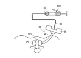
- the tubular portion 98 also serves as a tubular portion provided in the outer tube 96 for inserting and removing the main body 92 of the inner needle 91 in a puncture device 90 described later used for introducing the implant 20 into the living body ( 4A and 4B).
- the folded implant 20 is introduced into the cylindrical portion 98 of the outer cylinder 96, and the cylindrical portion 98 guides the movement of the implant 20 to the indwelling position in the living body. Since the cylindrical portion 98 of the guide means 30 also serves as the cylindrical portion of the outer cylinder 96 of the puncture device 90, the puncture device 90 will be described in detail first.
- the puncture device 90 includes an inner needle 91 that is punctured by a living body, and an outer cylinder 96 that is used by being assembled to the inner needle 91.
- the inner needle 91 has a main body portion 92 provided with a needle portion 93 at the tip.
- the outer cylinder 96 has a grip part 97 and a cylinder part 98 into which the main body part 92 of the inner needle 91 can be inserted and removed.
- the inner needle 91 and the outer cylinder 96 are fixed to each other in a state where the main body 92 of the inner needle 91 is inserted into the cylinder part 98 of the outer cylinder 96 (see FIG. 4B). Fixing is performed by screwing with a screw portion (not shown) formed in the main body portion 92 of the inner needle 91 and the tube portion 98 of the outer tube 96.
- the implant 20 is introduced, the inner needle 91 and the outer cylinder 96 are assembled and the needle portion 93 of the inner needle 91 is punctured into the living body 120 (see FIG. 6B).
- the inner needle 91 is separated from the outer cylinder 96, the main body portion 92 of the inner needle 91 is extracted from the cylinder portion 98, and the inner needle 91 is extracted from the living body 120 as it is.
- the implant 20 is introduced into a predetermined part of the living body 120 by using the cylindrical part 98 of the guide means 30 that also serves as the cylindrical part of the outer cylinder 96. At this time, the body fluid hardly enters from the opening tip of the guide means 30. Thus, the body fluid hardly penetrates from the tip of the opening because the above-described puncture device 90 is punctured between bones, between cartilages, in cartilage, or in bones in the living body. This is because lymph and tissue fluid are not blood but lymph fluid and tissue fluid have lower pressure and slower fluid flow than blood.
- the guide means 30 constituted by the tubular portion 98 can prevent the implant 20 and the body fluid from contacting with each other in the living body, and can be placed in the living body.
- the movement of the implant 20 into the can be guided. For this reason, it can prevent that the friction coefficient of the coating
- Examples of the material constituting the guide means 30 include polycarbonate, polyolefin (for example, polyethylene, polypropylene, ethylene-propylene copolymer), styrene resin [for example, polystyrene, MS resin (methacrylate-styrene copolymer), MBS resin ( Methacrylate-butylene-styrene copolymer)], synthetic resins such as polyester, metals such as stainless steel, aluminum or aluminum alloys, and the like.
- polycarbonate for example, polyethylene, polypropylene, ethylene-propylene copolymer
- styrene resin for example, polystyrene, MS resin (methacrylate-styrene copolymer), MBS resin ( Methacrylate-butylene-styrene copolymer)
- synthetic resins such as polyester, metals such as stainless steel, aluminum or aluminum alloys, and the like.
- the outer shape of the inner needle 91 is not particularly limited as long as it can puncture a living body, and may have, for example, an outer shape that is linearly extended.
- the cylindrical portion 98 of the outer cylinder 96 into which the inner needle is inserted is configured to have a shape that matches the outer shape of the inner needle 91.
- a puncture device 90 in which an inner needle 91 and an outer cylinder 96 are assembled is prepared.
- the puncture device 90 is introduced into the living body 120.
- the distal end portion of the inner needle 91 and the distal end portion of the outer cylinder 96 are positioned between the spinous processes.
- the inner needle 91 is separated from the outer cylinder 96 and pulled out.
- the implant 20 before expansion deformation is introduced into the living body 120 through the guide means of the inner needle 91.
- the implant 20 is led out from the distal end of the outer cylinder 96 and positioned between the spinous processes 123.
- the implant 20 can be introduced by a practitioner using a hand or by using a pushing member such as a rod or a tube.
- the implant 20 is expanded and deformed by introducing a filler into the implant 20.
- a filler supply unit 110 for pumping these fillers can be used.
- a known indeflator, a syringe, or the like can be used for the filler supply unit 110.
- connection to the filler supply unit 110 is performed via a connector 87 provided in the tubular member 83.
- the filler can be introduced by pouring or pushing the filler into the guide means 30 of the outer cylinder 96 without using the filler supply unit 110.
- the contrast agent is filled into the implant 20 before performing the work of filling the filler.
- the implant 20 is preliminarily expanded, so that the expansion operation with the filler can be performed smoothly.
- the introduction position of the implant 20 and the final expanded shape can be confirmed by performing X-ray fluoroscopy with the contrast agent filled.
- the contrast agent is sucked and discharged from the interior of the implant 20 by an indeflator, a syringe or the like before the filler is introduced.
- the tubular member 83 is separated from the implant 20. Thereafter, the outer cylinder 96 of the puncture member is removed from the living body 120.
- the implant 20 is placed between the spinous processes 123 and is used as a spacer for maintaining a space between the spinous processes 123.
- the expanded shape of the implant 20 is maintained over a long period of time by the filled filler.
- the implant assembly 10 includes the implant 20 and the guide means 30.
- the implant 20 is coated on at least a part of its surface with a coating material m whose friction coefficient is increased by contact with the liquid. For this reason, since the coating material m on the surface of the implant 20 and the body fluid come into contact with each other in the living body and the friction coefficient is increased, the implant 20 can be smoothly moved without being displaced from the positioned indwelling position when the filler is injected. Can be expanded.
- the guide means 30 prevents the implant 20 from contacting the body fluid in the living body and guides the movement of the implant 20 to the indwelling position in the living body. For this reason, it can prevent that the friction coefficient of the coating
- the surface of the implant 20 in the folded and contracted state is covered with the first surface portion 23 exposed to the outside, and only the second surface portion 22 located inside the first surface portion 23. Since the covering material m is covered with the covering material m, it is possible to suitably prevent the covering material m and the body fluid from coming into contact with each other when the body fluid enters the guide means 30 during the movement to the detention position. For this reason, it can prevent that the friction coefficient of the coating
- the implant assembly 10 that is placed between the bones of the living body, between the cartilage, in the cartilage, or in the bone, and is easy to introduce into the living body without being displaced.
- the implant 20 is provided at both ends of the body portion 21 extending in the longitudinal direction and the body portion 21, and has a width in the direction intersecting the longitudinal direction in a state after expansion is larger than that of the body portion 21.
- the covering material m is provided only on the wide portion 22. Since the implant 20 has such a shape, if the covering material m is provided on the surface of the wide portion 22 having the largest change amount and the largest contact area with the living body at least before and after the expansion deformation of the implant 20, the filler It is possible to prevent the implant 20 from being displaced from the indwelling position where the implant 20 is positioned. As shown in FIG. 9, the covering material m is provided on the entire circumference of the wide portion 22 of the implant 20.
- the implant 20 can be smoothly moved without being displaced from the positioned indwelling position.
- the implant 20 is provided at both ends of the trunk portion 21 extending in the longitudinal direction and the trunk portion 21, and the width in the direction intersecting the longitudinal direction in the expanded state is the trunk portion. And a wide portion 22 larger than 21. Since the implant has such a shape, the covering material m is provided in the wide portion 22 that has the largest change amount and the largest contact area with the living body at least before and after the expansion deformation of the implant 20, so the filler is injected. It is possible to prevent the implant 20 from being displaced from the indwelling position where the implant 20 is positioned.
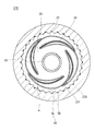
- the friction reducing means 40 for reducing the friction between the implant 20 and the guide means 230 is provided on at least a part of the inner surface of the guide means 230.
- the implant assembly 210 is different from the implant assembly 10 of the first embodiment in that such friction reducing means 40 is provided on the inner surface of the guide means 230.
- the guide unit 230 includes a lumen 231 through which the implant 20 can be inserted, and a friction reduction unit 40 that reduces friction between the implant 20 and the friction reduction unit is formed by the guide unit 230 formed by the lumen 231. It is provided on at least a part of the inner surface.
- the friction reducing means 40 is configured by forming the inner surface of the guide means 230 into an uneven shape. By forming the inner surface of the guide means 230 into an uneven shape, the groove 41 is formed on the inner surface of the guide means 230.
- the groove 41 is formed on the inner surface of the guide means 230 in order to reduce the contact area when the implant 20 comes into contact with the inner surface of the guide means 230. Since such a groove
- the groove 41 is formed on the inner surface of the guide means 230 in order to retract the body fluid when the body fluid enters the inner surface from the opening tip of the guide means 230.
- the groove 41 is formed on the inner surface of the guide means 230 by a predetermined length from the opening tip of the guide means 230.
- the groove 41 prevents the coating material m coated on the surface of the implant 20 from reacting with the body fluid and increasing the friction coefficient during the movement of the implant 20 to the indwelling position in the living body. For this reason, the guide means 230 in which the groove 41 is formed on the inner surface does not hinder the introduction of the implant 20 into the living body, and can smoothly introduce the implant 20 into the living body.
- an absorbent material 50 capable of absorbing body fluid is provided in the concave groove 41 formed on the inner surface of the guide means 230.
- the absorbent 50 is provided at the bottom of the groove 41 in order to hold the body fluid retreated in the groove 41.
- the absorbent 50 absorbs the bodily fluid withdrawn in the groove 41 when the bodily fluid enters the inner surface of the guide means 230. Therefore, during the movement of the implant 20 to the indwelling position in the living body, The coated covering material m is prevented from reacting with the body fluid and increasing the friction coefficient. For this reason, the guide means 230 in which the absorbent material 50 is provided in at least a part of the groove 41 can smoothly introduce the implant 20 into the living body.
- a water-absorbing polymer such as an acrylic acid polymer, a resin obtained by polymerizing a water-soluble monomer such as polyacrylamide, polyvinyl alcohol, or polyethylene glycol, or an acrylonitrile-based polymer compound can be used.
- the friction reducing means 40 is provided on the inner surface of the guide means 230, the friction between the implant 20 and the guide means 230 is reduced, whereby the implant 20 Can be smoothly introduced into the living body.
- the inner surface of the guide means 230 is formed in an uneven shape, the contact area between the implant 20 and the guide means 230 is reduced, and the implant 20 can be smoothly introduced into the living body. Further, even when body fluid enters the inner surface of the guide means 230, the body fluid can be retracted into the concave groove 41. For this reason, when moving the implant 20 to the indwelling position in the living body, it is possible to prevent the covering material m on the surface of the implant 20 from contacting the body fluid. Therefore, it is possible to prevent the friction coefficient of the covering material m on the surface of the implant 20 from being increased during the movement to the indwelling position, and thereby the implant 20 can be smoothly introduced into the living body.
- the absorbent 50 capable of absorbing bodily fluid is provided in the concave groove 41 formed on the inner surface of the guide means 230, the bodily fluid retreated in the groove 41 is retained. Can do. For this reason, when moving the implant 20 to the indwelling position in the living body, it is possible to more reliably prevent the covering material m on the surface of the implant 20 from contacting the body fluid. Therefore, it is possible to more reliably prevent the friction coefficient of the covering material m on the surface of the implant 20 from being increased during the movement to the indwelling position, and thereby the implant 20 can be smoothly introduced into the living body.
- the friction reducing means 340 has a low friction material 342.
- the implant assembly 310 is different from the implant assembly 210 of the second embodiment in that the configuration of the friction reducing means 340 provided on the inner surface of the guide means 330 is different.
- the friction reducing means 340 is composed of a low friction material 342 coated on the inner surface of the guide means 330.
- the low friction material 342 is a coating layer coated on the inner surface of the guide means 330 and is made of a material having high water repellency. Since the low friction material 342 has high water repellency, when the body fluid intrudes into the inner surface of the guide means 330 while the implant 20 is being moved to the indwelling position by the guide means 330, the body fluid repels the body fluid and the body fluid opens the guide means 330. Prevents intrusion from the tip into the inner surface. For this reason, the low friction material 342 can prevent the coating material m coated on the surface of the implant 20 from reacting with the body fluid and increasing the friction coefficient during the movement of the implant 20 to the indwelling position in the living body.
- the low friction material 342 for example, a fluorine-based polymer such as Teflon, a paraxylylene-based polymer such as parylene, a lubricating polymer such as polyethylene oxide, amorphous carbon such as diamond-like carbon, silicon oil, or the like can be used.
- the material of the low friction material 342 can be appropriately changed without limitation as long as the material prevents the friction coefficient between the surface of the implant 20 and the inner surface of the guide means 330 from increasing.
- the guide means 330 has a lumen 331 into which the implant 20 can be inserted.
- the friction reducing means 340 is composed of the low friction material 342 coated on the inner surface of the guide means 330, so that the friction between the implant 20 and the guide means 330 is reduced. Reduced more reliably. For this reason, it can prevent that the friction coefficient of the coating
- the friction reducing means 340 can be provided with a simple structure that only has to cover the inner surface of the guide means 330 with the coating layer (low friction material 342) as compared with the structure of the second embodiment. It can be configured.
- the guide means 30 has been described as a structure that also serves as the cylinder portion 98 of the outer cylinder 96 of the puncture device 90.
- the present invention is not limited to this, and the cylinder of the outer cylinder 96 of the puncture tool 90 is not limited thereto.
- the part 98 may be a separate member.
- the groove 41 is described as having a predetermined length formed on the inner surface of the guide means 230 from the opening tip of the guide means 30.
- the present invention is not limited to this, and the groove 41 is a guide.
- the inner surface of the means 230 may be configured not to reach the opening tip of the guide means 30. With such a configuration, it is possible to prevent body fluid from entering the inner surface of the guide means 30 from the opening tip of the guide means 30 by capillary action.
- the groove 41 is provided as the friction reducing means 40.
- the present invention is not limited to this, and for example, an uneven shape, a dimple shape, an embossed shape, a protrusion shape, a lattice shape, and the like.
- a process for reducing the contact area between the implant 20 and the inner surface of the guide means 30 may be applied to the inner surface of the guide means 30.
- the guide means 230 has been described as providing the groove 41 and the absorbent 50 as the friction reducing means 40 as shown in FIG. Only 41 may be provided.
- the method of introducing the implant 20 into the living body 120 using the puncture device 90 including the inner needle 91 and the outer cylinder 96 has been described.
- the method of introducing the implant 20 is not limited to this. Absent. As long as introduction into a predetermined site in a living body can be performed, it can be appropriately changed. For example, it is possible to employ a method of performing puncturing and implant introduction in one step using a puncture needle or the like provided with a body part into which the implant can be inserted and held.
- the implant 20 can exhibit an effect that can reduce the load on the living body at the time of placement only by the implant 20. For this reason, it is possible to use only the implant 20 for the procedure without using it as the implant assembly 10 combined with the tubular member 83 as described in the embodiment.
- 10, 210, 310 implant assembly 20 implants, 21 torso, 22 Wide part, 23 first surface portion, 24 second surface portion, 30, 230, 330 guide means, 31, 231, 331 lumens, 40, 340 friction reducing means, 41 grooves, 50 absorbent material, 60 inlet, 83 tubular member, 87 connector, 90 Puncture tool, 91 Inner needle, 92 body, 93 needle, 96 outer cylinder, 97 gripping part, 98 tube section, 110 Filler supply section, 120 living body, 121 back, 123 Spinous processes, 125 vertebral bodies, 126 Lumbar spine, 127 lamina, 128 pedicles, 129 intervertebral disc, 342 low friction material, m Coating material.
Abstract
[Problem] The objective of the present invention is to provide an implant assembly (10) whereby it is possible to smoothly place a folded implant (20) within a body, and to smoothly expand the implant (20) without misaligning the implant (20) from an aligned placement site when injecting a filling material. [Solution] An implant assembly, comprising: an implant (20), which is configured to be transformable from a folded and collapsed state to an expanded state by introducing a filling material therein, and in which at least a portion of the surface thereof is covered by a covering material (m) having a friction coefficient that increases by contact with bodily fluid; and a guide means (30) for preventing contact between the implant (20) and bodily fluid within the body, and for guiding the movement of the implant (20) to the placement site within the body.
Description
本発明は、生体内に留置されるインプラントを備えるインプラント組立体に関する。
The present invention relates to an implant assembly including an implant placed in a living body.
医療分野において生体内に留置されるインプラントに関する技術やインプラントの生体内への留置方法に関する各種技術が知られている。
In the medical field, various techniques relating to implants placed in vivo and methods for placing implants in vivo are known.
このようなインプラントとして、たとえば特許文献1には、充填材の導入により拡張するインプラントの発明が開示されている。このインプラントは、折り畳まれた状態で経皮的に生体内に留置される。生体内に留置されたインプラントは、充填材が注入される側の端部(基部側)から充填材が充填され拡張していく。このとき、体の中の構造物がインプラントの外表面と接触または干渉した状態でインプラントに充填材が注入されると、インプラント内に充填材が均一に行き渡らず、不均一に拡張してしまう場合がある。不均一に拡張するインプラントに充填材を注入し続けると、注入圧により体の中の構造物と接触または干渉している部分に押圧力がかかる。この押圧力の反作用によりインプラントが留置位置からずれてしまうことがある。このため、決められた位置に留置されたインプラントに充填材を注入する場合において、インプラントが留置位置から位置ずれすることを防止するための方法が必要とされている。
As such an implant, for example, Patent Document 1 discloses an invention of an implant that expands by introducing a filler. This implant is placed in the living body percutaneously in a folded state. The implant placed in the living body is filled with the filler and expanded from the end (base side) on the side where the filler is injected. At this time, if the filler is injected into the implant in a state where the structure in the body is in contact with or interferes with the outer surface of the implant, the filler does not spread evenly in the implant and expands unevenly. There is. If the filling material is continuously injected into the non-uniformly expanding implant, a pressing force is applied to a portion in contact with or interfering with a structure in the body due to the injection pressure. The reaction of this pressing force may cause the implant to deviate from the indwelling position. For this reason, in the case of injecting a filler into an implant placed at a predetermined position, a method for preventing the implant from being displaced from the placement position is required.
一方で、特許文献2には、折り畳まれたバルーンカテーテルの表面を初めから粘着性が高い物質を被覆することにより、バルーンが拡張した際にバルーンの位置ずれを防止するバルーンカテーテルの発明が開示されている。
On the other hand, Patent Document 2 discloses an invention of a balloon catheter that prevents the displacement of the balloon when the balloon is expanded by covering the surface of the folded balloon catheter with a highly adhesive substance from the beginning. ing.
たとえば、このような表面を初めから粘着性が高い物質を被覆する技術をインプラントに転用することにより、インプラントの留置位置からの位置ずれを防止できると考えられる。
For example, it is considered that displacement of the implant from the indwelling position can be prevented by diverting a technique for coating such a surface with a highly adhesive substance from the beginning to the implant.
しかしながら、折り畳まれたインプラントの表面を初めから粘着性が高い物質で覆った場合、粘着性を有する物質が張り付いてしまい、インプラントに充填材を注入してもインプラントが拡張しにくくなってしまう。また、インプラントの表面を初めから粘着性が高い物質で覆った場合、インプラントの生体内への導入を円滑に行うことができない。
However, when the surface of the folded implant is covered with a highly sticky substance from the beginning, the sticky substance sticks, and it becomes difficult to expand the implant even if a filler is injected into the implant. Moreover, when the surface of the implant is covered with a highly adhesive substance from the beginning, the implant cannot be smoothly introduced into the living body.
そこで、本発明は、上記課題を解決するためになされたものであり、折り畳まれたインプラントを円滑に生体内へ導入することができ、かつ充填材を注入する際にはインプラントを位置決めされた留置位置から位置ずれさせることなく円滑に拡張させることができるインプラント組立体を提供することを目的とする。
Therefore, the present invention has been made to solve the above-described problems, and can be used to smoothly introduce a folded implant into a living body and to place the implant in a position when injecting a filler. An object of the present invention is to provide an implant assembly that can be smoothly expanded without being displaced from the position.
上記目的は、下記(1)~(8)に記載のいずれかの手段により達成される。
The above object is achieved by any of the means described in (1) to (8) below.
(1)充填材が導入されることにより、折り畳まれて収縮した状態から拡張した状態へ変形可能に構成されており、かつ、体液と接触することにより摩擦係数が高まる被覆材が表面の少なくとも一部に被覆されたインプラントと、生体内において前記インプラントと生体の体液とが接触することを防止するとともに、生体内の留置位置への前記インプラントの移動をガイドするガイド手段と、を有するインプラント組立体。
(1) When the filler is introduced, it is configured to be deformable from a folded and contracted state to an expanded state, and at least one surface of the covering material whose friction coefficient is increased by contact with body fluid. Implant assembly comprising: an implant coated on a portion; and guide means for preventing the implant from contacting the body fluid in the living body and guiding the movement of the implant to the indwelling position in the living body .
(2)折り畳まれて収縮した状態の前記インプラントの表面には、外部に露出される第1表面部と、前記第1表面部に覆われて前記第1表面部の内側に位置する第2表面部とが形成されており、前記被覆材は、前記第2表面部のみに被覆される、上記(1)に記載のインプラント組立体。
(2) On the surface of the implant in a folded and contracted state, a first surface portion exposed to the outside, and a second surface that is covered with the first surface portion and is located inside the first surface portion The implant assembly according to (1) above, wherein the covering material is covered only on the second surface portion.
(3)前記インプラントは、長手方向に伸びる胴部と、前記胴部の両端に設けられ、拡張後の状態において前記長手方向と交差する方向の幅が前記胴部よりも大きくなる幅広部とを有しており、前記被覆材は、前記幅広部のみに設けられる、上記(1)または上記(2)に記載のインプラント組立体。
(3) The implant includes a trunk portion extending in a longitudinal direction, and a wide portion provided at both ends of the trunk portion, and having a width in a direction intersecting the longitudinal direction larger than that of the trunk portion in a state after expansion. The implant assembly according to (1) or (2), wherein the covering material is provided only in the wide portion.
(4)前記ガイド手段は、前記インプラントを挿通可能なルーメンと、前記ルーメンによって形成される前記ガイド手段の内表面の少なくとも一部に設けられる前記インプラントとの間の摩擦を低減する摩擦低減手段とを有する、上記(1)~(3)のいずれか1項に記載のインプラント組立体。
(4) The guide means includes friction reducing means for reducing friction between a lumen through which the implant can be inserted and the implant provided on at least a part of an inner surface of the guide means formed by the lumen. The implant assembly according to any one of (1) to (3), comprising:
(5)前記摩擦低減手段は、前記ガイド手段の内表面を凹凸形状に形成することによって構成される、上記(4)に記載のインプラント組立体。
(5) The implant assembly according to (4), wherein the friction reduction unit is configured by forming an inner surface of the guide unit in an uneven shape.
(6)前記ガイド手段の内表面に形成された凹状の溝内には、体液を吸収可能な吸収材が設けられる、上記(5)に記載のインプラント組立体。
(6) The implant assembly according to (5), wherein an absorbent material capable of absorbing bodily fluid is provided in a concave groove formed on the inner surface of the guide means.
(7)前記摩擦低減手段は、前記ガイド手段の内表面に被覆された低摩擦材から構成される、上記(4)に記載のインプラント組立体。
(7) The implant assembly according to (4), wherein the friction reducing means is made of a low friction material coated on an inner surface of the guide means.
(8)前記インプラントは、生体の骨間、軟骨間、軟骨内、または骨内を拡張するために用いられる、上記(1)~(7)のいずれか1項に記載のインプラント組立体。
(8) The implant assembly according to any one of (1) to (7), wherein the implant is used to expand between bones of bones, between cartilages, within cartilage, or within bones.
上記(1)に記載の発明によれば、インプラント組立体は、インプラントと、ガイド手段と、を有している。インプラントには、液体と接触することにより摩擦係数が高まる被覆材が表面の少なくとも一部に被覆されている。このため、生体内においてインプラントの表面の被覆材と体液とが接触して摩擦係数が高まるので、充填材を注入する際にインプラントを位置決めされた留置位置から位置ずれさせることなく円滑に拡張させることができる。ガイド手段は、生体内においてインプラントと生体の体液とが接触することを防止するとともに、生体内の留置位置へのインプラントの移動をガイドする。このため、留置位置への移動中においてインプラントの表面の被覆材の摩擦係数が高まることを防止でき、これにより、インプラントを円滑に生体内に導入することができる。
According to the invention described in (1) above, the implant assembly has an implant and guide means. The implant is coated on at least a part of its surface with a coating material that increases the coefficient of friction by contact with the liquid. For this reason, since the coating material on the surface of the implant and the body fluid come into contact with each other in the living body and the friction coefficient is increased, the implant can be smoothly expanded without being displaced from the positioned indwelling position when the filler is injected. Can do. The guide means prevents the implant from contacting the body fluid in the living body and guides the movement of the implant to the indwelling position in the living body. For this reason, it can prevent that the friction coefficient of the coating | covering material of the surface of an implant increases during the movement to an indwelling position, and, thereby, an implant can be smoothly introduce | transduced in a biological body.
上記(2)に記載の発明によれば、折り畳まれて収縮した状態のインプラントの表面は、外部に露出される第1表面部に覆われて第1表面部の内側に位置する第2表面部のみに上記被覆材が被覆されるため、留置位置へ移動中にガイド手段内に体液が浸入するような場合において、被覆材と体液が接触することを好適に防止できる。このため、留置位置への移動中においてインプラントの表面の被覆材の摩擦係数が高まることを防止でき、これにより、インプラントを円滑に生体内に導入することができる。
According to the invention described in (2) above, the surface of the folded and contracted implant is covered with the first surface portion exposed to the outside, and the second surface portion is located inside the first surface portion. Since the covering material is only covered, it is possible to suitably prevent the covering material and the body fluid from coming into contact with each other when the body fluid enters the guide means during the movement to the indwelling position. For this reason, it can prevent that the friction coefficient of the coating | covering material of the surface of an implant increases during the movement to an indwelling position, and, thereby, an implant can be smoothly introduce | transduced in a biological body.
上記(3)に記載の発明によれば、インプラントは、長手方向に伸びる胴部と、胴部の両端に設けられ、拡張後の状態において長手方向と交差する方向の幅が胴部よりも大きくなる幅広部とを有している。インプラントがこのような形状であるため、少なくともインプラントの拡張変形の前後において変化量が最も大きく生体との接触面積も最も大きい幅広部に被覆材を設けているので、充填材を注入する際にインプラントが位置決めされた留置位置から位置ずれすることを防止できる。
According to the invention described in (3) above, the implant is provided at the body portion extending in the longitudinal direction and at both ends of the body portion, and in the expanded state, the width in the direction intersecting the longitudinal direction is larger than that of the body portion. And a wide portion. Since the implant has such a shape, since the covering material is provided in the wide part having the largest change amount and the largest contact area with the living body at least before and after the expansion deformation of the implant, the implant is injected when the filler is injected. Can be prevented from being displaced from the indwelling position where it is positioned.
上記(4)に記載の発明によれば、ガイド手段の内表面に摩擦低減手段が設けられているので、インプラントとガイド手段との間の摩擦が低減され、これにより、インプラントを円滑に生体内に導入することができる。
According to the invention described in (4) above, since the friction reducing means is provided on the inner surface of the guide means, the friction between the implant and the guide means is reduced. Can be introduced.
上記(5)に記載の発明によれば、ガイド手段の内表面を凹凸形状に形成するので、インプラントとガイド手段との接触面積が小さくなりインプラントを円滑に生体内に導入することができる。また、ガイド手段の内表面に体液が浸入するような場合においても、凹状の溝内に体液を退避させることができる。このため、インプラントを生体内の留置位置へ移動する際、インプラントの表面の被覆材と体液とが接触することを防止できる。したがって、留置位置への移動中においてインプラントの表面の被覆材の摩擦係数が高まることを防止でき、これにより、インプラントを円滑に生体内に導入することができる。
According to the invention described in (5) above, since the inner surface of the guide means is formed in an uneven shape, the contact area between the implant and the guide means is reduced, and the implant can be smoothly introduced into the living body. Further, even when the body fluid enters the inner surface of the guide means, the body fluid can be retracted into the concave groove. For this reason, when the implant is moved to the indwelling position in the living body, it is possible to prevent the covering material on the surface of the implant and the body fluid from coming into contact with each other. Therefore, it is possible to prevent the friction coefficient of the coating material on the surface of the implant from being increased during the movement to the indwelling position, and thereby the implant can be smoothly introduced into the living body.
上記(6)に記載の発明によれば、ガイド手段の内表面に形成された凹状の溝内には、体液を吸収可能な吸収材が設けられるので、溝内に退避させた体液を保持することができる。このため、インプラントを生体内の留置位置へ移動する際、インプラントの表面の被覆材と体液とが接触することをより確実に防止することができる。したがって、留置位置への移動中においてインプラントの表面の被覆材の摩擦係数が高まることをより確実に防止でき、これにより、インプラントを円滑に生体内に導入することができる。
According to the invention described in (6) above, since the absorbent material capable of absorbing bodily fluid is provided in the concave groove formed on the inner surface of the guide means, the bodily fluid retreated in the groove is retained. be able to. For this reason, when moving an implant to the indwelling position in a biological body, it can prevent more reliably that the coating | covering material and body fluid of the surface of an implant contact. Therefore, it is possible to more reliably prevent an increase in the friction coefficient of the coating material on the surface of the implant during the movement to the indwelling position, and thereby the implant can be smoothly introduced into the living body.
上記(7)に記載の発明によれば、摩擦低減手段は、ガイド手段の内表面に被覆された低摩擦材から構成されるので、インプラントとガイド手段との間の摩擦がより確実に低減される。このため、留置位置への移動中においてインプラントの表面の被覆材の摩擦係数が高まることを防止でき、これにより、インプラントを円滑に生体内に導入することができる。
According to the invention described in (7) above, since the friction reducing means is composed of the low friction material coated on the inner surface of the guide means, the friction between the implant and the guide means is more reliably reduced. The For this reason, it can prevent that the friction coefficient of the coating | covering material of the surface of an implant increases during the movement to an indwelling position, and, thereby, an implant can be smoothly introduce | transduced in a biological body.
上記(8)に記載の発明によれば、生体の骨間、軟骨間、軟骨内、または骨内において留置され、位置ずれせず、生体内に導入しやすいインプラント組立体を提供することができる。
According to the invention described in (8) above, it is possible to provide an implant assembly that is placed between bones, between cartilages, within cartilage, or within bones of a living body, and does not shift in position and can be easily introduced into the living body. .
(第1の実施形態)
以下、図面を参照しつつ、本発明を実施形態に基づいて説明する。図面の説明において同一の要素には同一の符号を付し、重複する説明を省略する。図面の寸法比率は、説明の都合上誇張されており、実際の比率とは異なる場合がある。 (First embodiment)
Hereinafter, the present invention will be described based on embodiments with reference to the drawings. In the description of the drawings, the same elements are denoted by the same reference numerals, and redundant description is omitted. The dimensional ratios in the drawings are exaggerated for convenience of explanation, and may differ from actual ratios.
本実施形態では、生体内の隣接する棘突起間にインプラントを導入するために用いられる医療器具として本発明を適用した形態を例示する。まず、図5A、図5B、図5Cを参照して、インプラント20が留置される生体の棘突起や治療対象となる疾患について簡単に説明する。
This embodiment exemplifies a form in which the present invention is applied as a medical instrument used for introducing an implant between adjacent spinous processes in a living body. First, with reference to FIG. 5A, FIG. 5B, and FIG. 5C, the spinous process of the biological body in which the implant 20 is indwelled, and the disease used as a treatment target are demonstrated easily.
図5Aは、生体の背中側から棘突起を透視した様子を模式的に示す図であり、図5Bは、図5Aの棘突起の周辺部分を拡大して示す図であり、図5Cは、棘突起の配列方向(背骨の延伸方向)と直交する方向における生体の断面(横断面)を模式的に示す図である。各図において示すX軸は、棘突起の配列方向と直交する方向を示し、Y軸は、棘突起の配列方向を示し、Z軸は、生体の厚み方向を示す。
FIG. 5A is a diagram schematically showing a perspective view of the spinous process from the back side of the living body, FIG. 5B is an enlarged view of the peripheral portion of the spinous process of FIG. 5A, and FIG. It is a figure which shows typically the cross section (transverse section) of the biological body in the direction orthogonal to the arrangement direction (extension direction of a spine) of a processus | protrusion. The X axis shown in each figure indicates the direction orthogonal to the arrangement direction of the spinous processes, the Y axis shows the arrangement direction of the spinous processes, and the Z axis shows the thickness direction of the living body.
生体120の背中121には、背骨の延伸方向に沿って複数の腰椎126が配列されている(図5B参照)。この腰椎126は、前半分の椎体125と後半分の椎弓板127とが椎弓根128を介して連結された構成を有している(図5B、図5C参照)。椎弓板127には、棘突起123、横突起(肋骨突起)、上関節突起、下関節突起などの各種の突起が形成されている。腰椎126は、正常では軽く生体120の前方側に弯曲した形となる。また、隣接する椎体125は椎間板(椎間円板)129を介して連結されており、ある椎体と当該椎体に隣接する椎体とは、椎間板129や、上関節突起および下関節突起の間に存在する椎間関節等によってずれないようになっている(図5B参照)。
A plurality of lumbar vertebrae 126 are arranged on the back 121 of the living body 120 along the extending direction of the spine (see FIG. 5B). The lumbar vertebra 126 has a configuration in which a front half vertebral body 125 and a latter half vertebral disc 127 are connected via a pedicle 128 (see FIGS. 5B and 5C). On the lamina 127, various processes such as spinous processes 123, lateral processes (radial processes), upper joint processes, lower joint processes, and the like are formed. The lumbar vertebra 126 is normally lightly bent toward the front side of the living body 120. Adjacent vertebral bodies 125 are connected via an intervertebral disc (intervertebral disc) 129, and a vertebral body and a vertebral body adjacent to the vertebral body are intervertebral disc 129, upper joint process, and lower joint process. (See FIG. 5B).
例えば、スポーツなどで繰り返し腰椎126に負荷がかかり疲労骨折等が生じたような場合には、椎弓根128の部分で椎体125と椎弓板127とが分離してしまう腰椎分離症や、椎間関節の変形や椎間板129の変性によって上側に位置する腰椎126が固定されにくくなり、ずれが生じる腰椎変性すべり症が引き起こされることがある。これら腰椎分離症、腰椎変性すべり症や、腰椎の周囲に配置される靱帯が加齢に伴い変性することで脊柱管が狭窄し、腰部脊柱管狭窄症の症状である間欠性跛行が引き起こされることがある。このような腰部脊柱管狭窄症の治療方法として、隣接する棘突起123の間にスペーサとして機能し得るインプラント20を留置することにより脊柱管の狭窄を抑える治療方法が存在する(図8A、8B参照)。本実施形態では、このインプラント20を留置する留置手技にインプラント組立体10が使用される。
For example, when a load is repeatedly applied to the lumbar vertebra 126 in sports or the like and a fatigue fracture or the like occurs, lumbar sequestration in which the vertebral body 125 and the lamina 127 are separated at the pedicle 128 portion, Deformation of the intervertebral joints and degeneration of the intervertebral disc 129 may make it difficult to fix the lumbar vertebra 126 located on the upper side, and may cause lumbar degenerative slippage that causes a shift. These lumbar spondylosis, lumbar spondylolisthesis, and ligaments placed around the lumbar vertebrae degenerate with age, causing the spinal canal to narrow and cause intermittent claudication that is a symptom of lumbar spinal canal stenosis There is. As a treatment method for such lumbar spinal canal stenosis, there is a treatment method for suppressing spinal canal stenosis by placing an implant 20 that can function as a spacer between adjacent spinous processes 123 (see FIGS. 8A and 8B). ). In the present embodiment, the implant assembly 10 is used for an indwelling procedure for indwelling the implant 20.
次に、本実施形態に係るインプラント組立体10の構成について説明する。
Next, the configuration of the implant assembly 10 according to this embodiment will be described.
本発明の第1実施形態に係るインプラント組立体10は、概説すると、図1、図3Aおよび図3Bに示すように、充填材が導入されることにより、折り畳まれて収縮した状態から拡張した状態へ変形可能に構成されており、かつ、体液と接触することにより摩擦係数が高まる被覆材mが表面の少なくとも一部に被覆されたインプラント20と、生体内においてインプラント20と生体の体液とが接触することを防止するとともに、生体内の留置位置へのインプラント20の移動をガイドするガイド手段30とを有している。このように、インプラント20およびガイド手段30によってインプラント組立体10が構成される。
Briefly, the implant assembly 10 according to the first embodiment of the present invention is expanded from a collapsed and contracted state by introducing a filler as shown in FIGS. 1, 3A, and 3B. The implant 20 is configured so as to be deformable and has a coating material m on which at least a part of the surface is coated with a coating material m whose friction coefficient is increased by contact with the body fluid, and the implant 20 and the body fluid of the living body contact each other in the living body. And guide means 30 for guiding the movement of the implant 20 to the indwelling position in the living body. Thus, the implant assembly 10 is constituted by the implant 20 and the guide means 30.
まず、インプラント20について詳述する。
First, the implant 20 will be described in detail.
インプラント20は、折り畳まれて収縮した状態で生体120内へ導入される(図7Aを参照。)。また、棘突起123近傍の留置位置へ位置決めされた後、内部に充填材を注入されることにより拡張変形させられ、拡張変形された状態で留置される(図7Bを参照)。このとき、生体120内においてインプラント20の表面の被覆材mと体液とが接触して摩擦係数が高まるので、充填材を注入する際にインプラント20を位置決めされた留置位置から位置ずれさせることなく円滑に拡張させることができる。このように、インプラント20は、生体の骨間、軟骨間、軟骨内、または骨内を拡張するために用いられることができる。
The implant 20 is introduced into the living body 120 in a folded and contracted state (see FIG. 7A). Further, after being positioned at the indwelling position in the vicinity of the spinous process 123, it is expanded and deformed by injecting a filler therein, and is indwelled in an expanded and deformed state (see FIG. 7B). At this time, since the coating material m on the surface of the implant 20 and the body fluid come into contact with each other in the living body 120 and the friction coefficient is increased, the implant 20 can be smoothly moved without being displaced from the indwelling position where the implant 20 is positioned. Can be extended. In this way, the implant 20 can be used to expand between bones, between cartilages, within cartilage, or within bones of a living body.
拡張変形後のインプラント20には、長手方向に伸びる胴部21、および胴部21よりも大きな幅を備える幅広部22が形成される。胴部21は、インプラント20の中央部分に形成され、胴部21を間に挟むようにしてインプラント20の両端部に幅広部22が形成される。拡張変形後のインプラント20は、外形形状がダンベル型(略H型)形状となる。インプラント20の胴部21において隣接する棘突起123の間隔が保持される。また、インプラント20の両端部に位置する幅広部22において棘突起123が挟み込まれることによって留置後におけるインプラント20の位置ずれが防止される。なお、インプラント20の拡張前後における形状は、拡張変形したインプラントによって生体内の骨を支持したり、骨同士の間の間隔を保持したりするスペーサとしての機能が発揮し得る限りにおいて適宜変更することが可能である。本実施形態では、拡張変形後のインプラント20は、外形形状がダンベル型(略H型)形状として説明したが、たとえば幅広部がない一定形状であるストレート形状、たとえば中央部から端部にかけて徐々に幅が広がる形状である砂時計形状であってもよい。
In the implant 20 after the expansion deformation, a body part 21 extending in the longitudinal direction and a wide part 22 having a larger width than the body part 21 are formed. The body portion 21 is formed at the center portion of the implant 20, and wide portions 22 are formed at both ends of the implant 20 so as to sandwich the body portion 21 therebetween. The implant 20 after expansion deformation has a dumbbell (substantially H-shaped) outer shape. The interval between the adjacent spinous processes 123 is maintained in the trunk portion 21 of the implant 20. Further, the spinous processes 123 are sandwiched between the wide portions 22 located at both ends of the implant 20, thereby preventing the positional displacement of the implant 20 after placement. The shape of the implant 20 before and after expansion may be changed as long as it can function as a spacer that supports the bone in the living body by the expanded and deformed implant and maintains the distance between the bones. Is possible. In the present embodiment, the implant 20 after the expansion deformation has been described as having a dumbbell-shaped (substantially H-shaped) outer shape, but, for example, a straight shape having a constant shape without a wide portion, for example, gradually from the center to the end. It may be an hourglass shape that is wide in shape.
本実施形態では、被覆材mをインプラント20の表面の少なくとも一部に被覆する構成として説明するが、被覆材mの具体的な被覆位置について下記に詳述する。
In the present embodiment, the covering material m is described as a configuration in which at least a part of the surface of the implant 20 is covered, but a specific covering position of the covering material m will be described in detail below.
図2に示すように、折り畳まれて収縮した状態のインプラント20の表面には、外部に露出される第1表面部23と、第1表面部23に覆われて第1表面部23の内側に位置する第2表面部24とが形成されており、被覆材mは、第2表面部24のみに被覆される。
As shown in FIG. 2, the surface of the implant 20 in the folded and contracted state is exposed to the first surface portion 23 that is exposed to the outside, and is covered with the first surface portion 23 and inside the first surface portion 23. A second surface portion 24 is formed, and the covering material m is covered only by the second surface portion 24.
インプラント20は、折り畳まれて収縮した状態においては、外部に露出される第1表面部23に覆われた第1表面部23の内側に位置する第2表面部24のみに被覆材mが被覆されている。このため、インプラント20がガイド手段30により留置位置へ移動中にガイド手段30内に体液が浸入しても、被覆材mは、第1表面部23に覆われた第2表面部24のみに被覆されているので、体液と接触しない。このため、インプラント20の生体内への導入を阻害せず、インプラント20を円滑に生体内に導入することができる。
In the state where the implant 20 is folded and contracted, only the second surface portion 24 located inside the first surface portion 23 covered with the first surface portion 23 exposed to the outside is covered with the covering material m. ing. Therefore, even if the body fluid enters the guide means 30 while the implant 20 is moved to the indwelling position by the guide means 30, the covering material m is covered only on the second surface portion 24 covered by the first surface portion 23. So that it does not come into contact with body fluids. For this reason, the implant 20 can be smoothly introduced into the living body without inhibiting the introduction of the implant 20 into the living body.
折り畳まれた状態のインプラント20の第2表面部24のみに被覆されている被覆材mは、インプラント20に充填材が充填されると、図3Bに示すように、インプラント20の表面に剥き出しになる。インプラント20の表面に剥き出しになった被覆材mは、体液と接触して摩擦係数が高まる。
As shown in FIG. 3B, the covering material m covered only on the second surface portion 24 of the folded implant 20 is exposed on the surface of the implant 20 as shown in FIG. 3B. . The covering material m exposed on the surface of the implant 20 comes into contact with the body fluid and increases the coefficient of friction.
インプラント20の基材としては、ポリエステル系樹脂基材、ポリアミド系樹脂基材、ポリオレフィン系樹脂基材、ポリイミド系樹脂基材、エチレン・ビニルアルコール共重合体基材、ポリ塩化ビニル系樹脂基材などのプラスチック基材、あるいはこれらを組み合わせたもの、あるいはこれらにマット処理、コロナ放電処理、プラズマ処理、紫外線照射処理、電子線照射処理、フレームプラズマ処理およびオゾン処理、あるいは各種易接着処理などなどの表面処理を施したものなどの公知のものから選択して用いることができる。
Examples of the base material for the implant 20 include a polyester resin base material, a polyamide resin base material, a polyolefin resin base material, a polyimide resin base material, an ethylene / vinyl alcohol copolymer base material, and a polyvinyl chloride resin base material. Surfaces such as plastic substrates, combinations of these, matte treatment, corona discharge treatment, plasma treatment, ultraviolet irradiation treatment, electron beam irradiation treatment, flame plasma treatment and ozone treatment, or various easy adhesion treatments. It can select and use from well-known things, such as what processed.
インプラント20の拡張は、インプラント20の内部に固体や流体(気体、液体、ゲル)等の各種の充填材を充填させて行うことが可能であり、充填材の材質は特に限定されない。ただし、拡張状態を長期に亘って維持させるためには、充填材として、固体、またはインプラント20の内部への導入時には流動体で導入後に硬化する硬化材(以下、単に「硬化材」とも記載する)を用いることが好ましい。
The expansion of the implant 20 can be performed by filling the inside of the implant 20 with various fillers such as a solid or a fluid (gas, liquid, gel), and the material of the filler is not particularly limited. However, in order to maintain the expanded state for a long period of time, as a filler, a solid or a hardener that is cured after introduction with a fluid when introduced into the implant 20 (hereinafter also simply referred to as “hardener”). ) Is preferably used.
被覆材mの材料としては、たとえば天然品、化学修飾天然品、合成品、あるいはこれらの2種類以上の混合物などが用いられる。上記材料の具体例として、たとえば合成品としてはポリビニルアルコール、ポリビニルメチルエーテル、ポリビニルピロリドン、ポリアクリルアミド、ポリエチレンオキシド、ポリアクリル酸含有ポリマー、ポリカルボン酸含有ポリマー、カチオン性樹脂、ポリ-N-ビニル-2-ピロリドン、スチレン-無水マレイン酸共重合体、エチレン-無水マレイン酸共重合体など、合成品としては寒天、デンプン、蛋白質類、カラゲニン、グアーガム、アラビアガム、トラガントガム、ローカストビーンガム、化学修飾天然品としてはカチオン性デンプン、デキストラン、ヒドロキシアルキルデンプン、メチルセルロース、ナトリウムカルボキシメチルセルロース、ザンサンガム、デキストリンなどを挙げることができる。
As the material of the covering material m, for example, a natural product, a chemically modified natural product, a synthetic product, or a mixture of two or more of these is used. Specific examples of the above materials include, for example, synthetic products such as polyvinyl alcohol, polyvinyl methyl ether, polyvinyl pyrrolidone, polyacrylamide, polyethylene oxide, polyacrylic acid-containing polymer, polycarboxylic acid-containing polymer, cationic resin, poly-N-vinyl- Synthetic products such as 2-pyrrolidone, styrene-maleic anhydride copolymer, ethylene-maleic anhydride copolymer, agar, starch, proteins, carrageenin, guar gum, gum arabic, tragacanth gum, locust bean gum, chemically modified natural Examples of the product include cationic starch, dextran, hydroxyalkyl starch, methylcellulose, sodium carboxymethylcellulose, xanthan gum, and dextrin.
また、被覆材mには、相溶性のある液状可塑剤、充填材、またはこれらの両方を含有させることができる。液状可塑剤を含有させると湿潤粘着剤の柔軟性が向上すると共に、体液、水や親水性媒体の吸収性も良好となるので、速やかな粘着性の発揮につながる。また、充填材を含有させると、被覆材の機械的強度を向上させることができる。
Further, the coating material m can contain a compatible liquid plasticizer, filler, or both. The inclusion of a liquid plasticizer improves the flexibility of the wet pressure-sensitive adhesive and improves the absorbability of body fluids, water, and hydrophilic media, leading to rapid adhesion. Moreover, when a filler is contained, the mechanical strength of the coating material can be improved.
液状可塑剤としては、アルキレングリコール、ポリアルキレングリコール、グリセリン、ポリグリセリン、ソルビトールを用いることがよく、これらのうちの種類もしくは二種類以上を併用して含有させることができる。
As the liquid plasticizer, it is preferable to use alkylene glycol, polyalkylene glycol, glycerin, polyglycerin, or sorbitol, and these can be used in combination of two or more.
被覆材mの形成方法は、被覆材mを溶媒に溶解もしくは分散させた溶液にインプラント20をディッピングさせる方法や、溶液をインプラント20表面にスプレーさせる方法など公知なものから選択して用いることができる。この溶媒としては、たとえばアルコール、アセトン、テトラヒドロフラン、ジメチルスルホキシド、水、ヘキサンのような有機溶媒を用いる。
The method for forming the coating material m can be selected from known methods such as a method of dipping the implant 20 in a solution in which the coating material m is dissolved or dispersed in a solvent, and a method of spraying the solution onto the surface of the implant 20. . As this solvent, for example, an organic solvent such as alcohol, acetone, tetrahydrofuran, dimethyl sulfoxide, water or hexane is used.
充填材としては、ポリメタクリル酸メチルなどの有機充填材や、シリカ、アルミナ、酸化亜鉛、酸化チタン、タルク、クレー、カオリン、ガラスなどの無機酸化物ないしは無機複合酸化物、硫酸バリウム、炭酸カルシウム、リン酸カルシウム、ハイドロキシアパタイト、セラミックス、カーボン、などの無機充填材ならびにステンレス、チタン、ニッケル・チタン合金などの金属充填物(ワイヤ、コイル形状など)のうちの一種類以上を用いることができる。インプラント20内へ導入させられた後、インプラント20の留置された状態が体動により損なわれることなく維持されるため、インプラント20を拡張変形させた状態で長期に亘って棘突起123間のスペーサとして機能させることができる。
Examples of fillers include organic fillers such as polymethyl methacrylate, inorganic oxides such as silica, alumina, zinc oxide, titanium oxide, talc, clay, kaolin, and glass, inorganic composite oxides, barium sulfate, calcium carbonate, One or more of inorganic fillers such as calcium phosphate, hydroxyapatite, ceramics, carbon, and metal fillers (wire, coil shape, etc.) such as stainless steel, titanium, nickel / titanium alloy can be used. After being introduced into the implant 20, the indwelled state of the implant 20 is maintained without being damaged by body movement, so that the implant 20 is expanded and deformed as a spacer between the spinous processes 123 over a long period of time. Can function.
硬化材は、好ましくは、下記特性の少なくとも一つを有する:(a)患者に安全である;(b)組織への損傷が少ないもしくはない;(c)患者の体温に近い温度(約35~42℃)で硬化可能である;(d)収縮や拡張が起こらず、硬化した形状を維持できる;(e)注入してから1~60分、好ましくは5~30分、より好ましくは10分以内に硬化する;(f)溶媒として水、緩衝溶液、生理食塩液、造影剤、またはオリーブ油、ひまし油などの油脂類が使用できる。
The hardener preferably has at least one of the following properties: (a) safe for the patient; (b) little or no tissue damage; (c) a temperature close to the patient's body temperature (about 35- (D) No shrinkage or expansion can be maintained and the cured shape can be maintained; (e) 1 to 60 minutes after injection, preferably 5 to 30 minutes, more preferably 10 minutes (F) As a solvent, water, buffer solution, physiological saline, contrast medium, or oils and fats such as olive oil and castor oil can be used.
また、硬化材の具体例としては、(g)二液混合架橋ポリマー;(h)ホットメルト接着剤;(i)ウレタンエラストマー;(j)光硬化性樹脂;(k)アクリル系樹脂;(l)骨セメント;(m)外部刺激により結晶化する溶液などが挙げられる。
Specific examples of the curing material include: (g) two-component mixed crosslinked polymer; (h) hot melt adhesive; (i) urethane elastomer; (j) photocurable resin; (k) acrylic resin; ) Bone cement; (m) solutions that crystallize upon external stimulation.
上記(g)において、二液混合架橋ポリマーとしては、芳香族ジエポキシド樹脂または脂肪族ジエポキシド樹脂と、アミン化合物と、の組み合わせ、もしくは、反応性基を有するポリオルガノシロキサンと、架橋剤と、硬化触媒と、の組み合わせが好ましい。
In the above (g), the two-component mixed crosslinked polymer may be a combination of an aromatic diepoxide resin or aliphatic diepoxide resin and an amine compound, or a polyorganosiloxane having a reactive group, a crosslinking agent, and a curing catalyst. The combination of and is preferred.
上記(h)において、ホットメルト接着剤としては、水と反応して硬化できる材料と水との組み合わせ、またはEVA(エチレン酢酸ビニル共重合体)系、PO(ポリオレフィン)系、PA(ポリアミド)系、SR(合成ゴム)系、ACR(アクリル)系、PUR(ポリウレタン・湿気硬化型)系等が挙げられる。
In the above (h), as the hot melt adhesive, a combination of a material that can be cured by reacting with water and water, EVA (ethylene vinyl acetate copolymer) system, PO (polyolefin) system, PA (polyamide) system SR (synthetic rubber) system, ACR (acrylic) system, PUR (polyurethane / moisture curing type) system, and the like.
上記(i)において、ウレタンエラストマーとしては、ポリオールと芳香族ポリイソシアネートとから誘導される重合体が好ましい。
In the above (i), the urethane elastomer is preferably a polymer derived from a polyol and an aromatic polyisocyanate.
上記(j)において、光重合性モノマーとしては、アクリル酸エステル、メタクリル酸エステル、エチレン性不飽和カルボン酸など挙げられ、重合促進剤、架橋剤、光重合開始剤などを必要により使用することができる。
In the above (j), examples of the photopolymerizable monomer include acrylic acid esters, methacrylic acid esters, and ethylenically unsaturated carboxylic acids. A polymerization accelerator, a crosslinking agent, a photopolymerization initiator, and the like may be used as necessary. it can.
上記(k)において、アクリル系樹脂としては、(メタ)アクリル酸メチル、(メタ)
アクリル酸エチル、(メタ)アクリル酸ブチル、(メタ)アクリル酸n-ヘキシル、(メ
タ)アクリル酸シクロヘキシル、(メタ)アクリル酸2-エチルへキシル、(メタ)アクリル酸n-オクチル、(メタ)アクリル酸ノニル、(メタ)アクリル酸デシル、(メタ)アクリル酸、(メタ)アクリル酸グリシジル、酢酸ビニル、スチレン、α-メチルスチレン、(メタ)アクリルアミド、(メタ)アクリロニトリルなどのモノマーを公知の方法で重合したものが挙げられる。 In the above (k), examples of the acrylic resin include methyl (meth) acrylate, (meth)
Ethyl acrylate, butyl (meth) acrylate, n-hexyl (meth) acrylate, cyclohexyl (meth) acrylate, 2-ethylhexyl (meth) acrylate, n-octyl (meth) acrylate, (meth) Known methods for monomers such as nonyl acrylate, decyl (meth) acrylate, (meth) acrylic acid, glycidyl (meth) acrylate, vinyl acetate, styrene, α-methylstyrene, (meth) acrylamide, (meth) acrylonitrile And those polymerized in step (b).
上記(l)において、骨セメントは、例えばポリメチルメタクリレート、メチルメタクリレート-スチレン・コポリマー、過酸化ベンゾイル、硫酸バリウムなどの粉体に、メチルメタクリレート、N,N―ジメチル-パラ-トルイジン、ヒドロキノンなどからなる溶剤を混合し、作製される。または、酸化亜鉛とリン酸の酸塩基反応により硬化する歯科用セメントや、アルギン酸ナトリウム、リン酸ナトリウム、塩化カルシウムなどに溶剤を混合し、有機物であるアルギン酸ナトリウム、無機物であるリン酸カルシウムが作製される有機-無機複合材なども使用できる。
In the above (l), the bone cement is made of, for example, polymethylmethacrylate, methylmethacrylate-styrene copolymer, benzoyl peroxide, barium sulfate, etc. into methyl methacrylate, N, N-dimethyl-para-toluidine, hydroquinone, etc. It is produced by mixing the solvent. Or, organic cement from which organic cement sodium alginate and inorganic calcium phosphate are produced by mixing a solvent with dental cement that hardens by acid-base reaction of zinc oxide and phosphoric acid, sodium alginate, sodium phosphate, calcium chloride, etc. -Inorganic composite materials can also be used.
上記(m)において、外部刺激により結晶化する溶液としては、酢酸ナトリウム、塩化ナトリウムなどを溶解させた水溶液が挙げられる。外部刺激としては、物理的衝撃、熱、光、電気、超音波などが挙げられる。
In the above (m), examples of the solution that crystallizes by external stimulation include aqueous solutions in which sodium acetate, sodium chloride, and the like are dissolved. Examples of the external stimulus include physical impact, heat, light, electricity, and ultrasonic waves.
充填材として導入時には流動体で導入後に硬化する硬化材を用いることにより、充填材に固体を用いる場合と同様にインプラント20を拡張変形させた状態で長期に亘って棘突起123間のスペーサとして機能させることができる。
When introduced as a filler, it functions as a spacer between the spinous processes 123 over a long period of time in a state where the implant 20 is expanded and deformed in the same manner as in the case of using a solid as the filler by using a hardening material that hardens after introduction with a fluid. Can be made.
インプラント20は、1つの導入口60が設けられる。導入口60は、生体への導入方向の近位側部分に設けられる。この導入口60を利用して充填材をインプラント20の内部へ充填させることが可能である。
The implant 20 is provided with one introduction port 60. The introduction port 60 is provided at a proximal portion in the introduction direction to the living body. The introduction port 60 can be used to fill the interior of the implant 20 with a filler.
導入口60を介してインプラント20の内部に充填材を送り込むために用いられる管状部材83は、導入口60と着脱可能な構成を有している。このような構成により、管状部材83は、インプラント20から着脱可能となっている。また、導入口60は、図示しないシール部を有しており、このシール部によりインプラント20と管状部材83との間を液密・気密な状態に維持することができる。その他の導入口60としては、脱着可能なルアーロック形状の継手、圧送管体自体を捻転することで脱着可能な雄雌ネジの継手などが挙げられる。
The tubular member 83 used for feeding the filler into the implant 20 through the introduction port 60 has a configuration that is detachable from the introduction port 60. With such a configuration, the tubular member 83 is detachable from the implant 20. Further, the introduction port 60 has a seal portion (not shown), and the seal portion can maintain a liquid-tight / air-tight state between the implant 20 and the tubular member 83. Examples of the other inlet 60 include a detachable luer lock-shaped joint, and a male / female threaded joint that can be detached by twisting the pumping tube itself.
インプラント20と管状部材83の分離は、管状部材83のインプラント20内部に挿入されている先端をインプラント20内部から引っ張り出すことによって行われる。管状部材83の先端が引っ張り出されると、上記シール部が弾性的に変形して導入口60を閉塞する。
The separation of the implant 20 and the tubular member 83 is performed by pulling out the tip of the tubular member 83 inserted into the implant 20 from the interior of the implant 20. When the distal end of the tubular member 83 is pulled out, the seal portion is elastically deformed to close the introduction port 60.
管状部材83は、内部に図示しないルーメンが形成されたチューブによって構成される。チューブは、例えば、医療分野等において広く用いられている公知の樹脂製チューブなどによって構成することができる。
The tubular member 83 is configured by a tube having a lumen (not shown) formed therein. A tube can be comprised by the well-known resin tube etc. which are widely used in the medical field etc., for example.
管状部材83の基端側には、充填材を送り込むための充填材供給部110(図7A、図7Bを参照)が接続されるコネクタ87が設けられる(図7Aを参照)。コネクタ87は、管状部材83のルーメン内を液密、気密に保持するための弁としての機能も備える。
A connector 87 to which a filler supply unit 110 (see FIGS. 7A and 7B) for feeding the filler is connected is provided on the proximal end side of the tubular member 83 (see FIG. 7A). The connector 87 also has a function as a valve for keeping the lumen of the tubular member 83 liquid-tight and air-tight.
管状部材83およびコネクタ87を構成する材料としては、例えば、生体適合性に優れた、ETFE(テトラフルオロ 4 エチレンエチレン共重合体)、PTFE(ポリテトラフルオロエチレン)等のフッ素樹脂、PE(ポリエチレン)、PP(ポリプロピレン)等のポリオレフィン、ポリアミド、ポリエステル、ポリウレタン等の熱可塑性樹脂が挙げられる。
Examples of the material constituting the tubular member 83 and the connector 87 include, for example, fluororesins such as ETFE (tetrafluoro 4 ethylene ethylene copolymer) and PTFE (polytetrafluoroethylene), PE (polyethylene), which are excellent in biocompatibility. , Polyolefins such as PP (polypropylene), and thermoplastic resins such as polyamide, polyester, and polyurethane.
つぎに、ガイド手段30について詳述する。
Next, the guide means 30 will be described in detail.
ガイド手段30は、上述したように生体内においてインプラント20と生体の体液とが接触することを防止する防止機能と、生体内の留置位置へのインプラント20の移動をガイドするガイド機能とを有する。
As described above, the guide means 30 has a preventing function for preventing the implant 20 from contacting the body fluid in the living body and a guiding function for guiding the movement of the implant 20 to the indwelling position in the living body.
図示する実施形態のガイド手段30は、筒部98を有している。この筒部98は、生体へのインプラント20の導入に用いられる後述する穿刺具90において、内針91の本体部92を挿入抜去するために外筒96に設けられた筒部を兼ねている(図4A、図4B参照)。
The guide means 30 in the illustrated embodiment has a cylindrical portion 98. The tubular portion 98 also serves as a tubular portion provided in the outer tube 96 for inserting and removing the main body 92 of the inner needle 91 in a puncture device 90 described later used for introducing the implant 20 into the living body ( 4A and 4B).
穿刺具90を生体に穿刺した後、外筒96の筒部98の内部に折り畳んだインプラント20を導入し、筒部98が生体内への留置位置へのインプラント20の移動をガイドする。ガイド手段30が有する筒部98が穿刺具90の外筒96の筒部を兼ねていることから、まず、穿刺具90について詳述する。
After puncturing the living body with the puncture device 90, the folded implant 20 is introduced into the cylindrical portion 98 of the outer cylinder 96, and the cylindrical portion 98 guides the movement of the implant 20 to the indwelling position in the living body. Since the cylindrical portion 98 of the guide means 30 also serves as the cylindrical portion of the outer cylinder 96 of the puncture device 90, the puncture device 90 will be described in detail first.
図4A、図4Bには生体へのインプラント20の導入に用いられる穿刺具90が示される。穿刺具90は、生体に穿刺される内針91と、内針91に組み付けて使用される外筒96とを有している。内針91は、先端に針部93が設けられた本体部92を有している。外筒96は、把持部97と、内針91の本体部92が挿入抜去可能な筒部98とを有している。
4A and 4B show a puncture device 90 used for introducing the implant 20 into a living body. The puncture device 90 includes an inner needle 91 that is punctured by a living body, and an outer cylinder 96 that is used by being assembled to the inner needle 91. The inner needle 91 has a main body portion 92 provided with a needle portion 93 at the tip. The outer cylinder 96 has a grip part 97 and a cylinder part 98 into which the main body part 92 of the inner needle 91 can be inserted and removed.
内針91の本体部92を外筒96の筒部98内に挿入させた状態で内針91と外筒96とが相互に固定される(図4Bを参照)。固定は、内針91の本体部92および外筒96の筒部98に形成された不図示のねじ部によってねじ止めして行われる。インプラント20の導入を行う際は、内針91と外筒96とを組み付けた状態とし、内針91の針部93を生体120に穿刺させる(図6Bを参照)。この状態で内針91を外筒96から分離させ、筒部98から内針91の本体部92を抜き取り、そのまま内針91を生体120から抜去させる。
The inner needle 91 and the outer cylinder 96 are fixed to each other in a state where the main body 92 of the inner needle 91 is inserted into the cylinder part 98 of the outer cylinder 96 (see FIG. 4B). Fixing is performed by screwing with a screw portion (not shown) formed in the main body portion 92 of the inner needle 91 and the tube portion 98 of the outer tube 96. When the implant 20 is introduced, the inner needle 91 and the outer cylinder 96 are assembled and the needle portion 93 of the inner needle 91 is punctured into the living body 120 (see FIG. 6B). In this state, the inner needle 91 is separated from the outer cylinder 96, the main body portion 92 of the inner needle 91 is extracted from the cylinder portion 98, and the inner needle 91 is extracted from the living body 120 as it is.
次に、ガイド手段30が有する上記防止機能および上記ガイド機能について詳述する。
Next, the prevention function and the guide function of the guide means 30 will be described in detail.
インプラント20は、外筒96の筒部を兼ねるガイド手段30の筒部98を利用して生体120の所定の部位へ導入される。このとき、ガイド手段30の開口先端から体液がほとんど浸入しない。このように、上記開口先端から体液がほとんど浸入しないのは、上述した穿刺具90が生体内の骨間、軟骨間、軟骨内、または骨内に穿刺されるので、浸入する体液とは主に血液ではなくリンパ液や組織液であり、リンパ液や組織液は血液と比べ、圧力が低く、液の流速が遅いためである。
The implant 20 is introduced into a predetermined part of the living body 120 by using the cylindrical part 98 of the guide means 30 that also serves as the cylindrical part of the outer cylinder 96. At this time, the body fluid hardly enters from the opening tip of the guide means 30. Thus, the body fluid hardly penetrates from the tip of the opening because the above-described puncture device 90 is punctured between bones, between cartilages, in cartilage, or in bones in the living body. This is because lymph and tissue fluid are not blood but lymph fluid and tissue fluid have lower pressure and slower fluid flow than blood.
筒部98から構成したガイド手段30は、上述したように、開口先端から体液がほとんど浸入しないので、生体内においてインプラント20と生体の体液とが接触することを防止できるとともに、生体内の留置位置へのインプラント20の移動をガイドすることができる。このため、留置位置への移動中においてインプラント20の表面の被覆材mの摩擦係数が高まることを防止でき、これにより、インプラント20を円滑に生体内に導入することができる。
As described above, since the body fluid hardly penetrates from the opening tip as described above, the guide means 30 constituted by the tubular portion 98 can prevent the implant 20 and the body fluid from contacting with each other in the living body, and can be placed in the living body. The movement of the implant 20 into the can be guided. For this reason, it can prevent that the friction coefficient of the coating | covering material m of the surface of the implant 20 increases during the movement to an indwelling position, and, thereby, the implant 20 can be smoothly introduce | transduced in the living body.
ガイド手段30を構成する材料としては、例えば、ポリカーボネート、ポリオレフィン(例えば、ポリエチレン、ポリプロピレン、エチレン-プロピレンコポリマー)、スチレン系樹脂[例えば、ポリスチレン、MS樹脂(メタクリレート-スチレン共重合体)、MBS樹脂(メタクリレート-ブチレン-スチレン共重合体)]、ポリエステルなどの合成樹脂、ステンレス鋼、アルミまたはアルミ合金などの金属等が挙げられうる。
Examples of the material constituting the guide means 30 include polycarbonate, polyolefin (for example, polyethylene, polypropylene, ethylene-propylene copolymer), styrene resin [for example, polystyrene, MS resin (methacrylate-styrene copolymer), MBS resin ( Methacrylate-butylene-styrene copolymer)], synthetic resins such as polyester, metals such as stainless steel, aluminum or aluminum alloys, and the like.
内針91の外形形状は、生体への穿刺を行うことが可能であれば特に制限はなく、例えば、直線状に延伸された外形形状を備えていてもよい。ただし、この場合、内針が挿入される外筒96の筒部98は、内針91の外形形状に合わせた形状を有するように構成される。
The outer shape of the inner needle 91 is not particularly limited as long as it can puncture a living body, and may have, for example, an outer shape that is linearly extended. However, in this case, the cylindrical portion 98 of the outer cylinder 96 into which the inner needle is inserted is configured to have a shape that matches the outer shape of the inner needle 91.
次に、実施形態に係るインプラント20の留置手順およびインプラント20の作用を説明する。
Next, the placement procedure of the implant 20 according to the embodiment and the operation of the implant 20 will be described.
図6Aを参照して、内針91と外筒96とが組み付けられた穿刺具90を準備する。
Referring to FIG. 6A, a puncture device 90 in which an inner needle 91 and an outer cylinder 96 are assembled is prepared.
図6Bを参照して、穿刺具90を生体120内に導入する。この際、内針91の先端部および外筒96の先端部を棘突起間に位置させる。次に、内針91を外筒96から分離させて引き抜く。
Referring to FIG. 6B, the puncture device 90 is introduced into the living body 120. At this time, the distal end portion of the inner needle 91 and the distal end portion of the outer cylinder 96 are positioned between the spinous processes. Next, the inner needle 91 is separated from the outer cylinder 96 and pulled out.
図7Aを参照して、内針91のガイド手段内を通して拡張変形前のインプラント20を生体120内へ導入させる。外筒96の先端からインプラント20を導出させて棘突起123間に位置させる。インプラント20の導入は、施術者が手を使って押し込んで行ったり、棒や管などの押し込み用の部材を使って押し込んで行ったりすることが可能である。
7A, the implant 20 before expansion deformation is introduced into the living body 120 through the guide means of the inner needle 91. The implant 20 is led out from the distal end of the outer cylinder 96 and positioned between the spinous processes 123. The implant 20 can be introduced by a practitioner using a hand or by using a pushing member such as a rod or a tube.
図7Bを参照して、インプラント20の内部に充填材を導入することによってインプラント20を拡張変形させる。
Referring to FIG. 7B, the implant 20 is expanded and deformed by introducing a filler into the implant 20.
充填材に硬化材や流動体を使用する場合には、これらの充填材を圧送するための充填材供給部110を用いることができる。充填材供給部110には、公知のインデフレーター、シリンジ等を使用することができる。また充填材供給部110を使う場合、管状部材83が備えるコネクタ87を介して充填材供給部110との接続が行われる。充填材に固体が用いられる場合は、充填材供給部110を用いずに、外筒96のガイド手段30内へ充填材を流し込んだり、押し込んだりすることによって導入を行うことが可能である。
When using a hardener or a fluid as the filler, a filler supply unit 110 for pumping these fillers can be used. A known indeflator, a syringe, or the like can be used for the filler supply unit 110. When the filler supply unit 110 is used, connection to the filler supply unit 110 is performed via a connector 87 provided in the tubular member 83. When a solid is used as the filler, the filler can be introduced by pouring or pushing the filler into the guide means 30 of the outer cylinder 96 without using the filler supply unit 110.
なお、充填材を充填する作業を行う前に、造影剤をインプラント20の内部に充填させる。このような作業を行うことにより、インプラント20が予備的に拡張されるため、充填材による拡張作業を円滑に行うことが可能になる。また、造影剤が充填された状態でX線透視を行うことにより、インプラント20の導入位置や最終的な拡張形状を確認することができる。造影剤は、充填材の導入前にインデフレーター、シリンジ等によって吸引してインプラント20の内部から排出する。
It should be noted that the contrast agent is filled into the implant 20 before performing the work of filling the filler. By performing such an operation, the implant 20 is preliminarily expanded, so that the expansion operation with the filler can be performed smoothly. Moreover, the introduction position of the implant 20 and the final expanded shape can be confirmed by performing X-ray fluoroscopy with the contrast agent filled. The contrast agent is sucked and discharged from the interior of the implant 20 by an indeflator, a syringe or the like before the filler is introduced.
図7A、図7Bを参照して、生体120内においてインプラント20を拡張させるときに、管状部材83内に充填材を送り込むと、インプラント20の拡張変形が開始する。このとき、折り畳まれたインプラント20の第2表面部24は、第1表面部23に覆われて第1表面部23の内側に位置していた状態から徐々に表側に移動する。インプラント20の表側に第2表面部24が移動すると、第2表面部24に被覆されている被覆材mは、体液と接触して摩擦係数が高まる。このため、生体内に留置したインプラント20に充填材を注入する際に、インプラント20は、留置位置から位置ずれすることなく拡張する。また、被覆材mがインプラント20の第2表面部24のみに被覆されているので、第1表面部23と第2表面部24とは互いに張り付いていない。このため、インプラント20は、円滑に拡張する。
7A and 7B, when the implant 20 is expanded in the living body 120, when the filler is fed into the tubular member 83, the expansion deformation of the implant 20 starts. At this time, the second surface portion 24 of the folded implant 20 gradually moves to the front side from the state of being covered with the first surface portion 23 and positioned inside the first surface portion 23. If the 2nd surface part 24 moves to the front side of the implant 20, the coating | covering material m coat | covered with the 2nd surface part 24 will contact a bodily fluid, and a friction coefficient will increase. For this reason, when the filler is injected into the implant 20 placed in the living body, the implant 20 expands without being displaced from the placement position. Further, since the covering material m is covered only on the second surface portion 24 of the implant 20, the first surface portion 23 and the second surface portion 24 are not attached to each other. For this reason, the implant 20 expands smoothly.
図7B、図8Aを参照して、インプラント20から管状部材83を分離させる。その後、穿刺部材の外筒96を生体120から抜去させる。インプラント20を棘突起123の間に留置させ、棘突起123間の間隔を保持するためのスペーサとして利用する。
7B and 8A, the tubular member 83 is separated from the implant 20. Thereafter, the outer cylinder 96 of the puncture member is removed from the living body 120. The implant 20 is placed between the spinous processes 123 and is used as a spacer for maintaining a space between the spinous processes 123.
図8A、図8Bを参照して、充填された充填材によってインプラント20の拡張形状が長期に亘って維持される。
Referring to FIG. 8A and FIG. 8B, the expanded shape of the implant 20 is maintained over a long period of time by the filled filler.
上述したように、本実施形態によれば、インプラント組立体10は、インプラント20と、ガイド手段30と、を有している。インプラント20には、液体と接触することにより摩擦係数が高まる被覆材mが表面の少なくとも一部に被覆されている。このため、生体内においてインプラント20の表面の被覆材mと体液とが接触して摩擦係数が高まるので、充填材を注入する際にインプラント20を位置決めされた留置位置から位置ずれさせることなく円滑に拡張させることができる。ガイド手段30は、生体内においてインプラント20と生体の体液とが接触することを防止するとともに、生体内の留置位置へのインプラント20の移動をガイドする。このため、留置位置への移動中においてインプラント20の表面の被覆材mの摩擦係数が高まることを防止でき、これにより、インプラント20を円滑に生体内に導入することができる。
As described above, according to the present embodiment, the implant assembly 10 includes the implant 20 and the guide means 30. The implant 20 is coated on at least a part of its surface with a coating material m whose friction coefficient is increased by contact with the liquid. For this reason, since the coating material m on the surface of the implant 20 and the body fluid come into contact with each other in the living body and the friction coefficient is increased, the implant 20 can be smoothly moved without being displaced from the positioned indwelling position when the filler is injected. Can be expanded. The guide means 30 prevents the implant 20 from contacting the body fluid in the living body and guides the movement of the implant 20 to the indwelling position in the living body. For this reason, it can prevent that the friction coefficient of the coating | covering material m of the surface of the implant 20 increases during the movement to an indwelling position, and, thereby, the implant 20 can be smoothly introduce | transduced in the living body.
また、上述したように、折り畳まれて収縮した状態のインプラント20の表面は、外部に露出される第1表面部23に覆われて第1表面部23の内側に位置する第2表面部22のみに上記被覆材mが被覆されるため、留置位置へ移動中にガイド手段30内に体液が浸入するような場合において、被覆材mと体液が接触することを好適に防止できる。このため、留置位置への移動中においてインプラント20の表面の被覆材mの摩擦係数が高まることを防止でき、これにより、インプラント20を円滑に生体内に導入することができる。
In addition, as described above, the surface of the implant 20 in the folded and contracted state is covered with the first surface portion 23 exposed to the outside, and only the second surface portion 22 located inside the first surface portion 23. Since the covering material m is covered with the covering material m, it is possible to suitably prevent the covering material m and the body fluid from coming into contact with each other when the body fluid enters the guide means 30 during the movement to the detention position. For this reason, it can prevent that the friction coefficient of the coating | covering material m of the surface of the implant 20 increases during the movement to an indwelling position, and, thereby, the implant 20 can be smoothly introduce | transduced in the living body.
また、上述したように、生体の骨間、軟骨間、軟骨内、または骨内において留置され、位置ずれせず、生体内に導入しやすいインプラント組立体10を提供することができる。
Also, as described above, it is possible to provide the implant assembly 10 that is placed between the bones of the living body, between the cartilage, in the cartilage, or in the bone, and is easy to introduce into the living body without being displaced.
(変形例)
次に、図9を参照して、本発明に係るインプラント20の表面に被覆される被覆材mの被覆位置の変形例について説明する。なお、上述した第1の実施形態と同一の部材には同一の符号を付して説明し、重複した説明は省略する。 (Modification)
Next, with reference to FIG. 9, the modification of the coating | coated position of the coating | covering material m coat | covered on the surface of theimplant 20 which concerns on this invention is demonstrated. In addition, the same code | symbol is attached | subjected and demonstrated to the member same as 1st Embodiment mentioned above, and the overlapping description is abbreviate | omitted.
次に、図9を参照して、本発明に係るインプラント20の表面に被覆される被覆材mの被覆位置の変形例について説明する。なお、上述した第1の実施形態と同一の部材には同一の符号を付して説明し、重複した説明は省略する。 (Modification)
Next, with reference to FIG. 9, the modification of the coating | coated position of the coating | covering material m coat | covered on the surface of the
本変形例にあっては、インプラント20は、長手方向に伸びる胴部21と、胴部21の両端に設けられ、拡張後の状態において長手方向と交差する方向の幅が胴部21よりも大きくなる幅広部22とを有しており、被覆材mは、幅広部22のみに設けられる。インプラント20がこのような形状であるため、少なくともインプラント20の拡張変形の前後において変化量が最も大きく生体との接触面積が最も大きい幅広部22の表面に被覆材mを設けておけば、充填材を注入する際にインプラント20が位置決めされた留置位置から位置ずれすることを防止できる。なお、図9に示すように、被覆材mは、インプラント20の幅広部22の全周に設けられている。このため、幅広部22の全周に被覆されている被覆材mと体液とが接触して被覆材mの摩擦係数が高まるので、インプラント20は、位置決めされた留置位置から位置ずれすることなく円滑に拡張する。
In this modification, the implant 20 is provided at both ends of the body portion 21 extending in the longitudinal direction and the body portion 21, and has a width in the direction intersecting the longitudinal direction in a state after expansion is larger than that of the body portion 21. The covering material m is provided only on the wide portion 22. Since the implant 20 has such a shape, if the covering material m is provided on the surface of the wide portion 22 having the largest change amount and the largest contact area with the living body at least before and after the expansion deformation of the implant 20, the filler It is possible to prevent the implant 20 from being displaced from the indwelling position where the implant 20 is positioned. As shown in FIG. 9, the covering material m is provided on the entire circumference of the wide portion 22 of the implant 20. For this reason, since the coating material m coated on the entire circumference of the wide portion 22 and the body fluid come into contact with each other and the friction coefficient of the coating material m increases, the implant 20 can be smoothly moved without being displaced from the positioned indwelling position. Extend to
なお、本変形例では、被覆材mをインプラント20の幅広部22にのみ被覆する構成について説明したが、これに限らず被覆材mをインプラント20の幅広部22で、かつインプラント20の第2表面部24に該当する表面に被覆する構成にしてもよい。このような構成にすることにより、留置位置へ移動中にガイド手段30内に体液が浸入するような場合において、被覆材mと体液が接触することを好適に防止することができる。このため、留置位置への移動中においてインプラント20の表面の被覆材mの摩擦係数が高まることを防止でき、これにより、インプラント20を円滑に生体内に導入することができる。
In addition, in this modification, although the structure which coat | covers the coating | covering material m only to the wide part 22 of the implant 20 was demonstrated, not only this but the coating | coated material m is the wide part 22 of the implant 20, and the 2nd surface of the implant 20 The surface corresponding to the portion 24 may be covered. By adopting such a configuration, it is possible to suitably prevent the covering material m and the body fluid from coming into contact with each other when the body fluid enters the guide means 30 during the movement to the indwelling position. For this reason, it can prevent that the friction coefficient of the coating | covering material m of the surface of the implant 20 increases during the movement to an indwelling position, and, thereby, the implant 20 can be smoothly introduce | transduced in the living body.
上述したように、本変形例によれば、インプラント20は、長手方向に伸びる胴部21と、胴部21の両端に設けられ、拡張後の状態において長手方向と交差する方向の幅が胴部21よりも大きくなる幅広部22とを有している。インプラントがこのような形状であるため、少なくともインプラント20の拡張変形の前後において変化量が最も大きく生体との接触面積も最も大きい幅広部22に被覆材mを設けているので、充填材を注入する際にインプラント20が位置決めされた留置位置から位置ずれすることを防止できる。
As described above, according to this modification, the implant 20 is provided at both ends of the trunk portion 21 extending in the longitudinal direction and the trunk portion 21, and the width in the direction intersecting the longitudinal direction in the expanded state is the trunk portion. And a wide portion 22 larger than 21. Since the implant has such a shape, the covering material m is provided in the wide portion 22 that has the largest change amount and the largest contact area with the living body at least before and after the expansion deformation of the implant 20, so the filler is injected. It is possible to prevent the implant 20 from being displaced from the indwelling position where the implant 20 is positioned.
(第2の実施形態)
次に、図10を参照して、第2の実施形態について説明する。なお、上述した第1の実施形態と同一の部材には同一の符号を付して説明し、重複した説明は省略する。 (Second Embodiment)
Next, a second embodiment will be described with reference to FIG. In addition, the same code | symbol is attached | subjected and demonstrated to the member same as 1st Embodiment mentioned above, and the overlapping description is abbreviate | omitted.
本実施形態にあっては、ガイド手段230の内表面の少なくとも一部にインプラント20とガイド手段230との間の摩擦を低減する摩擦低減手段40が設けられている。このような摩擦低減手段40がガイド手段230の内表面に設けられている点において、インプラント組立体210は、第1の実施形態のインプラント組立体10と相違している。
In this embodiment, the friction reducing means 40 for reducing the friction between the implant 20 and the guide means 230 is provided on at least a part of the inner surface of the guide means 230. The implant assembly 210 is different from the implant assembly 10 of the first embodiment in that such friction reducing means 40 is provided on the inner surface of the guide means 230.
ガイド手段230は、インプラント20を挿通可能なルーメン231と、インプラント20との間の摩擦を低減する摩擦低減手段40とを有しており、摩擦低減手段は、ルーメン231によって形成されるガイド手段230の内表面の少なくとも一部に設けられている。摩擦低減手段40は、ガイド手段230の内表面を凹凸形状に形成することによって構成されている。ガイド手段230の内表面を凹凸形状に形成することにより、ガイド手段230の内表面には、溝41が形成される。
The guide unit 230 includes a lumen 231 through which the implant 20 can be inserted, and a friction reduction unit 40 that reduces friction between the implant 20 and the friction reduction unit is formed by the guide unit 230 formed by the lumen 231. It is provided on at least a part of the inner surface. The friction reducing means 40 is configured by forming the inner surface of the guide means 230 into an uneven shape. By forming the inner surface of the guide means 230 into an uneven shape, the groove 41 is formed on the inner surface of the guide means 230.
溝41は、インプラント20がガイド手段230の内表面と接触した場合、接触面積を小さくするためにガイド手段230の内表面に形成されている。このような溝41が設けられているため、インプラントとガイド手段との接触面積が小さくなりインプラント20を円滑に生体内に導入することができる。
The groove 41 is formed on the inner surface of the guide means 230 in order to reduce the contact area when the implant 20 comes into contact with the inner surface of the guide means 230. Since such a groove | channel 41 is provided, the contact area of an implant and a guide means becomes small, and the implant 20 can be smoothly introduce | transduced in a biological body.
また、溝41は、ガイド手段230の開口先端から内表面に体液が浸入した場合、体液を退避させるためにガイド手段230の内表面に形成されている。溝41は、ガイド手段230の内表面において、ガイド手段230の開口先端から所定の長さ分形成されている。溝41は、インプラント20の生体内の留置位置への移動中において、インプラント20の表面に被覆された被覆材mが体液と反応して摩擦係数が高くなることを防止する。このため、溝41が内表面に形成されたガイド手段230は、インプラント20の生体内への導入を阻害せず、インプラント20を円滑に生体内に導入することができる。
Also, the groove 41 is formed on the inner surface of the guide means 230 in order to retract the body fluid when the body fluid enters the inner surface from the opening tip of the guide means 230. The groove 41 is formed on the inner surface of the guide means 230 by a predetermined length from the opening tip of the guide means 230. The groove 41 prevents the coating material m coated on the surface of the implant 20 from reacting with the body fluid and increasing the friction coefficient during the movement of the implant 20 to the indwelling position in the living body. For this reason, the guide means 230 in which the groove 41 is formed on the inner surface does not hinder the introduction of the implant 20 into the living body, and can smoothly introduce the implant 20 into the living body.
ガイド手段230の内表面に形成された凹状の溝41には、体液を吸収可能な吸収材50が設けられている。
In the concave groove 41 formed on the inner surface of the guide means 230, an absorbent material 50 capable of absorbing body fluid is provided.
吸収材50は、溝41内に退避された体液を保持するために、溝41の底部に設けられている。吸収材50は、ガイド手段230の内表面に体液が浸入した場合に溝41内に退避された体液を吸収するので、インプラント20の生体内の留置位置への移動中において、インプラント20の表面に被覆された被覆材mが体液と反応して摩擦係数が高くなることを防止する。このため、溝41内の少なくとも一部に吸収材50が設けられているガイド手段230は、インプラント20を円滑に生体内に導入することができる。
The absorbent 50 is provided at the bottom of the groove 41 in order to hold the body fluid retreated in the groove 41. The absorbent 50 absorbs the bodily fluid withdrawn in the groove 41 when the bodily fluid enters the inner surface of the guide means 230. Therefore, during the movement of the implant 20 to the indwelling position in the living body, The coated covering material m is prevented from reacting with the body fluid and increasing the friction coefficient. For this reason, the guide means 230 in which the absorbent material 50 is provided in at least a part of the groove 41 can smoothly introduce the implant 20 into the living body.
吸収材50としては、たとえばアクリル酸ポリマーなどの吸水ポリマー、ポリアクリルアミド、ポリビニルアルコール、ポリエチレングリコールなど水溶性モノマーを重合した樹脂、アクリロニトリル系高分子化合物を用いることができる。
As the absorbent 50, for example, a water-absorbing polymer such as an acrylic acid polymer, a resin obtained by polymerizing a water-soluble monomer such as polyacrylamide, polyvinyl alcohol, or polyethylene glycol, or an acrylonitrile-based polymer compound can be used.
上述したように、本実施形態によれば、ガイド手段230の内表面に摩擦低減手段40が設けられているので、インプラント20とガイド手段230との間の摩擦が低減され、これにより、インプラント20を円滑に生体内に導入することができる。
As described above, according to the present embodiment, since the friction reducing means 40 is provided on the inner surface of the guide means 230, the friction between the implant 20 and the guide means 230 is reduced, whereby the implant 20 Can be smoothly introduced into the living body.
また、上述したように、ガイド手段230の内表面を凹凸形状に形成するので、インプラント20とガイド手段230との接触面積が小さくなりインプラント20を円滑に生体内に導入することができる。また、ガイド手段230の内表面に体液が浸入するような場合においても、凹状の溝41内に体液を退避させることができる。このため、インプラント20を生体内の留置位置へ移動する際、インプラント20の表面の被覆材mと体液とが接触することを防止できる。したがって、留置位置への移動中においてインプラント20の表面の被覆材mの摩擦係数が高まることを防止でき、これにより、インプラント20を円滑に生体内に導入することができる。
Further, as described above, since the inner surface of the guide means 230 is formed in an uneven shape, the contact area between the implant 20 and the guide means 230 is reduced, and the implant 20 can be smoothly introduced into the living body. Further, even when body fluid enters the inner surface of the guide means 230, the body fluid can be retracted into the concave groove 41. For this reason, when moving the implant 20 to the indwelling position in the living body, it is possible to prevent the covering material m on the surface of the implant 20 from contacting the body fluid. Therefore, it is possible to prevent the friction coefficient of the covering material m on the surface of the implant 20 from being increased during the movement to the indwelling position, and thereby the implant 20 can be smoothly introduced into the living body.
また、上述したように、ガイド手段230の内表面に形成された凹状の溝41内には、体液を吸収可能な吸収材50が設けられるので、溝41内に退避させた体液を保持することができる。このため、インプラント20を生体内の留置位置へ移動する際、インプラント20の表面の被覆材mと体液とが接触することをより確実に防止することができる。したがって、留置位置への移動中においてインプラント20の表面の被覆材mの摩擦係数が高まることをより確実に防止でき、これにより、インプラント20を円滑に生体内に導入することができる。
Further, as described above, since the absorbent 50 capable of absorbing bodily fluid is provided in the concave groove 41 formed on the inner surface of the guide means 230, the bodily fluid retreated in the groove 41 is retained. Can do. For this reason, when moving the implant 20 to the indwelling position in the living body, it is possible to more reliably prevent the covering material m on the surface of the implant 20 from contacting the body fluid. Therefore, it is possible to more reliably prevent the friction coefficient of the covering material m on the surface of the implant 20 from being increased during the movement to the indwelling position, and thereby the implant 20 can be smoothly introduced into the living body.
(第3の実施形態)
次に、図11を参照して、第3の実施形態について説明する。なお、上述した第1および第2の実施形態と同一の部材には同一の符号を付して説明し、重複した説明は省略する。 (Third embodiment)
Next, a third embodiment will be described with reference to FIG. In addition, the same code | symbol is attached | subjected and demonstrated to the member same as 1st and 2nd embodiment mentioned above, and the overlapping description is abbreviate | omitted.
本実施形態にあっては、摩擦低減手段340は、低摩擦材342を有している。ガイド手段330の内表面に設けられた摩擦低減手段340の構成が異なる点において、インプラント組立体310は、第2実施形態のインプラント組立体210と相違している。
In this embodiment, the friction reducing means 340 has a low friction material 342. The implant assembly 310 is different from the implant assembly 210 of the second embodiment in that the configuration of the friction reducing means 340 provided on the inner surface of the guide means 330 is different.
摩擦低減手段340は、ガイド手段330の内表面に被覆された低摩擦材342から構成されている。
The friction reducing means 340 is composed of a low friction material 342 coated on the inner surface of the guide means 330.
低摩擦材342は、ガイド手段330の内表面に被覆された被覆層であり、撥水性の高い材質で構成されている。低摩擦材342は、撥水性が高いため、ガイド手段330によりインプラント20を留置位置へ移動中において、ガイド手段330の内表面に体液が浸入した場合、体液を弾き、体液がガイド手段330の開口先端から内表面に浸入することを防止する。このため、低摩擦材342は、インプラント20の生体内の留置位置への移動中において、インプラント20の表面に被覆された被覆材mが体液と反応して摩擦係数が高くなることを防止できる。
The low friction material 342 is a coating layer coated on the inner surface of the guide means 330 and is made of a material having high water repellency. Since the low friction material 342 has high water repellency, when the body fluid intrudes into the inner surface of the guide means 330 while the implant 20 is being moved to the indwelling position by the guide means 330, the body fluid repels the body fluid and the body fluid opens the guide means 330. Prevents intrusion from the tip into the inner surface. For this reason, the low friction material 342 can prevent the coating material m coated on the surface of the implant 20 from reacting with the body fluid and increasing the friction coefficient during the movement of the implant 20 to the indwelling position in the living body.
低摩擦材342としては、たとえばテフロンなどのフッ素系ポリマー、パリレンなどのパラキシリレン系ポリマー、ポリエチレンオキサイドなどの潤滑性ポリマー、ダイヤモンドライクカーボンなどのアモルファス炭素、シリコンオイルなどを用いることができる。なお、低摩擦材342の材質は、インプラント20の表面とガイド手段330の内表面との摩擦係数が高くなることを防止する材質であれば限定されることなく適宜変更することが可能である。
As the low friction material 342, for example, a fluorine-based polymer such as Teflon, a paraxylylene-based polymer such as parylene, a lubricating polymer such as polyethylene oxide, amorphous carbon such as diamond-like carbon, silicon oil, or the like can be used. The material of the low friction material 342 can be appropriately changed without limitation as long as the material prevents the friction coefficient between the surface of the implant 20 and the inner surface of the guide means 330 from increasing.
ガイド手段330は、インプラント20が挿入可能なルーメン331を有している。
The guide means 330 has a lumen 331 into which the implant 20 can be inserted.
上述したように、本実施形態によれば、摩擦低減手段340は、ガイド手段330の内表面に被覆された低摩擦材342から構成されるので、インプラント20とガイド手段330との間の摩擦がより確実に低減される。このため、留置位置への移動中においてインプラント20の表面の被覆材mの摩擦係数が高まることを防止でき、これにより、インプラント20を円滑に生体内に導入することができる。
As described above, according to the present embodiment, the friction reducing means 340 is composed of the low friction material 342 coated on the inner surface of the guide means 330, so that the friction between the implant 20 and the guide means 330 is reduced. Reduced more reliably. For this reason, it can prevent that the friction coefficient of the coating | covering material m of the surface of the implant 20 increases during the movement to an indwelling position, and, thereby, the implant 20 can be smoothly introduce | transduced in the living body.
このように、本実施形態によれば、第2実施形態の構成と比べ、ガイド手段330の内表面に被覆層(低摩擦材342)を被覆すればよい簡易な構成によって、摩擦低減手段340を構成することが可能となる。
As described above, according to the present embodiment, the friction reducing means 340 can be provided with a simple structure that only has to cover the inner surface of the guide means 330 with the coating layer (low friction material 342) as compared with the structure of the second embodiment. It can be configured.
上述した各実施形態は適宜変更することが可能である。
Each embodiment mentioned above can be changed suitably.
実施形態の説明においては、ガイド手段30を穿刺具90の外筒96の筒部98と兼用する構成として説明したが、これに限ることなく、ガイド手段30と穿刺具90の外筒96の筒部98とが別部材であってもよい。
In the description of the embodiment, the guide means 30 has been described as a structure that also serves as the cylinder portion 98 of the outer cylinder 96 of the puncture device 90. However, the present invention is not limited to this, and the cylinder of the outer cylinder 96 of the puncture tool 90 is not limited thereto. The part 98 may be a separate member.
また、実施形態の説明においては、溝41がガイド手段230の内表面においてガイド手段30の開口先端から所定の長さ分形成されている構成として説明したが、これに限らず、溝41がガイド手段230の内表面においてガイド手段30の開口先端に達していない構成にしてもよい。このような構成にすることにより、毛管現象によってガイド手段30の開口先端からガイド手段30の内表面に体液が浸入することを防止できる。
In the description of the embodiment, the groove 41 is described as having a predetermined length formed on the inner surface of the guide means 230 from the opening tip of the guide means 30. However, the present invention is not limited to this, and the groove 41 is a guide. The inner surface of the means 230 may be configured not to reach the opening tip of the guide means 30. With such a configuration, it is possible to prevent body fluid from entering the inner surface of the guide means 30 from the opening tip of the guide means 30 by capillary action.
また、実施形態の説明においては、摩擦低減手段40として溝41を設けているが、これに限ることなく、たとえば凹凸形状、ディンプル(くぼみ)状、エンボス(浮き出し)状、突起状、格子状などインプラント20とガイド手段30の内表面との接触面積が少なくなる加工がガイド手段30の内表面に施されていてもよい。
In the description of the embodiment, the groove 41 is provided as the friction reducing means 40. However, the present invention is not limited to this, and for example, an uneven shape, a dimple shape, an embossed shape, a protrusion shape, a lattice shape, and the like. A process for reducing the contact area between the implant 20 and the inner surface of the guide means 30 may be applied to the inner surface of the guide means 30.
また、実施形態の説明においては、ガイド手段230は、摩擦低減手段40として、図10に示すように、溝41および吸収材50を設けているとして説明したが、これに限ることなく、たとえば溝41のみを設ける構成にしてもよい。
In the description of the embodiment, the guide means 230 has been described as providing the groove 41 and the absorbent 50 as the friction reducing means 40 as shown in FIG. Only 41 may be provided.
また、実施形態の説明においては、内針91および外筒96を備える穿刺具90によってインプラント20を生体120内へ導入させる方法を説明したが、インプラント20の導入方法はこれに限定されるものではない。生体内の所定の部位への導入を行い得る限りにおいて適宜変更することが可能である。例えば、インプラントが挿入保持可能な胴部を備える穿刺針などを利用して、穿刺およびインプラントの導入を一つの工程で行う方法を採用することができる。
In the description of the embodiment, the method of introducing the implant 20 into the living body 120 using the puncture device 90 including the inner needle 91 and the outer cylinder 96 has been described. However, the method of introducing the implant 20 is not limited to this. Absent. As long as introduction into a predetermined site in a living body can be performed, it can be appropriately changed. For example, it is possible to employ a method of performing puncturing and implant introduction in one step using a puncture needle or the like provided with a body part into which the implant can be inserted and held.
インプラント20は、インプラント20のみで留置時の生体への負荷を低減し得る効果を発揮させることができる。このため、実施形態において説明したように管状部材83と組み合わせたインプラント組立体10として使用せずに、インプラント20のみを手技に用いることが可能である。
The implant 20 can exhibit an effect that can reduce the load on the living body at the time of placement only by the implant 20. For this reason, it is possible to use only the implant 20 for the procedure without using it as the implant assembly 10 combined with the tubular member 83 as described in the embodiment.
10、210、310 インプラント組立体、
20 インプラント、
21 胴部、
22 幅広部、
23 第1表面部、
24 第2表面部、
30、230、330 ガイド手段、
31、231、331 ルーメン、
40、340 摩擦低減手段、
41 溝、
50 吸収材、
60 導入口、
83 管状部材、
87 コネクタ、
90 穿刺具、
91 内針、
92 本体部、
93 針部、
96 外筒、
97 把持部、
98 筒部、
110 充填材供給部、
120 生体、
121 背中、
123 棘突起、
125 椎体、
126 腰椎、
127 椎弓板、
128 椎弓根、
129 椎間板、
342 低摩擦材、
m 被覆材。 10, 210, 310 implant assembly,
20 implants,
21 torso,
22 Wide part,
23 first surface portion,
24 second surface portion,
30, 230, 330 guide means,
31, 231, 331 lumens,
40, 340 friction reducing means,
41 grooves,
50 absorbent material,
60 inlet,
83 tubular member,
87 connector,
90 Puncture tool,
91 Inner needle,
92 body,
93 needle,
96 outer cylinder,
97 gripping part,
98 tube section,
110 Filler supply section,
120 living body,
121 back,
123 Spinous processes,
125 vertebral bodies,
126 Lumbar spine,
127 lamina,
128 pedicles,
129 intervertebral disc,
342 low friction material,
m Coating material.
Claims (8)
- 充填材が導入されることにより、折り畳まれて収縮した状態から拡張した状態へ変形可能に構成されており、かつ、体液と接触することにより摩擦係数が高まる被覆材が表面の少なくとも一部に被覆されたインプラントと、
生体内において前記インプラントと生体の体液とが接触することを防止するとともに、生体内の留置位置への前記インプラントの移動をガイドするガイド手段と、を有するインプラント組立体。 By introducing a filler, it is configured to be deformable from a folded and contracted state to an expanded state, and at least a part of the surface is coated with a coating material that increases the coefficient of friction by contact with body fluid. An implanted implant,
An implant assembly comprising: guide means for preventing the implant from contacting the body fluid in the living body and guiding the movement of the implant to an indwelling position in the living body. - 折り畳まれて収縮した状態の前記インプラントの表面には、外部に露出される第1表面部と、前記第1表面部に覆われて前記第1表面部の内側に位置する第2表面部とが形成されており、
前記被覆材は、前記第2表面部のみに被覆される、請求項1に記載のインプラント組立体。 On the surface of the implant that is folded and contracted, a first surface portion that is exposed to the outside and a second surface portion that is covered with the first surface portion and is located inside the first surface portion. Formed,
The implant assembly according to claim 1, wherein the covering material is covered only on the second surface portion. - 前記インプラントは、長手方向に伸びる胴部と、前記胴部の両端に設けられ、拡張後の状態において前記長手方向と交差する方向の幅が前記胴部よりも大きくなる幅広部とを有しており、
前記被覆材は、前記幅広部のみに設けられる、請求項1または請求項2に記載のインプラント組立体。 The implant has a trunk portion extending in a longitudinal direction, and a wide portion provided at both ends of the trunk portion and having a width in a direction intersecting the longitudinal direction in an expanded state that is larger than the trunk portion. And
The implant assembly according to claim 1, wherein the covering material is provided only in the wide portion. - 前記ガイド手段は、前記インプラントを挿通可能なルーメンと、
前記ルーメンによって形成される前記ガイド手段の内表面の少なくとも一部に設けられる前記インプラントとの間の摩擦を低減する摩擦低減手段とを有する、請求項1~3のいずれか1項に記載のインプラント組立体。 The guide means includes a lumen through which the implant can be inserted;
The implant according to any one of claims 1 to 3, further comprising friction reducing means for reducing friction with the implant provided on at least a part of an inner surface of the guide means formed by the lumen. Assembly. - 前記摩擦低減手段は、前記ガイド手段の内表面を凹凸形状に形成することによって構成される、請求項4に記載のインプラント組立体。 The implant assembly according to claim 4, wherein the friction reducing means is configured by forming an inner surface of the guide means in an uneven shape.
- 前記ガイド手段の内表面に形成された凹状の溝内には、体液を吸収可能な吸収材が設けられる、請求項5に記載のインプラント組立体。 The implant assembly according to claim 5, wherein an absorbent material capable of absorbing bodily fluid is provided in a concave groove formed on the inner surface of the guide means.
- 前記摩擦低減手段は、前記ガイド手段の内表面に被覆された低摩擦材から構成される、請求項4に記載のインプラント組立体。 The implant assembly according to claim 4, wherein the friction reducing means is composed of a low friction material coated on an inner surface of the guide means.
- 前記インプラントは、生体の骨間、軟骨間、軟骨内、または骨内を拡張するために用いられる、請求項1~7のいずれか1項に記載のインプラント組立体。 The implant assembly according to any one of claims 1 to 7, wherein the implant is used for expanding a living body between bones, between cartilage, inside cartilage, or inside bone.
Priority Applications (3)
| Application Number | Priority Date | Filing Date | Title |
|---|---|---|---|
| PCT/JP2013/060025 WO2014162499A1 (en) | 2013-04-02 | 2013-04-02 | Implant assembly |
| JP2015509752A JPWO2014162499A1 (en) | 2013-04-02 | 2013-04-02 | Implant assembly |
| US14/873,702 US9833329B2 (en) | 2013-04-02 | 2015-10-02 | Implant assembly |
Applications Claiming Priority (1)
| Application Number | Priority Date | Filing Date | Title |
|---|---|---|---|
| PCT/JP2013/060025 WO2014162499A1 (en) | 2013-04-02 | 2013-04-02 | Implant assembly |
Related Child Applications (1)
| Application Number | Title | Priority Date | Filing Date |
|---|---|---|---|
| US14/873,702 Continuation US9833329B2 (en) | 2013-04-02 | 2015-10-02 | Implant assembly |
Publications (1)
| Publication Number | Publication Date |
|---|---|
| WO2014162499A1 true WO2014162499A1 (en) | 2014-10-09 |
Family
ID=51657832
Family Applications (1)
| Application Number | Title | Priority Date | Filing Date |
|---|---|---|---|
| PCT/JP2013/060025 WO2014162499A1 (en) | 2013-04-02 | 2013-04-02 | Implant assembly |
Country Status (3)
| Country | Link |
|---|---|
| US (1) | US9833329B2 (en) |
| JP (1) | JPWO2014162499A1 (en) |
| WO (1) | WO2014162499A1 (en) |
Families Citing this family (2)
| Publication number | Priority date | Publication date | Assignee | Title |
|---|---|---|---|---|
| DE102013101334A1 (en) * | 2013-02-11 | 2014-08-14 | Acandis Gmbh & Co. Kg | Intravascular functional element and method for its production, use of a salt bath for heat treatment |
| US10821002B1 (en) * | 2019-12-10 | 2020-11-03 | Spica Medical Technologies, Llc | Inflatable spinal implants and related systems and methods |
Citations (5)
| Publication number | Priority date | Publication date | Assignee | Title |
|---|---|---|---|---|
| US5647846A (en) * | 1995-05-17 | 1997-07-15 | Scimed Life Systems, Inc. | Catheter having geometrically shaped surface and method of manufacture |
| JP2003510134A (en) * | 1999-09-28 | 2003-03-18 | シメッド ライフ システムズ インコーポレイテッド | Coating with hydrophilic lubricant for medical devices |
| JP2004507319A (en) * | 2000-08-28 | 2004-03-11 | ディスク ダイナミックス、 インコーポレーティッド | Artificial disc |
| JP2005514178A (en) * | 2002-01-04 | 2005-05-19 | ボストン サイエンティフィック リミテッド | Multi-wing balloon catheter reduces damage to coated expandable medical implants |
| JP2011502711A (en) * | 2007-11-16 | 2011-01-27 | ジンテス ゲゼルシャフト ミット ベシュレンクテル ハフツング | Porous containment device and related method for stabilizing vertebral compression fractures |
Family Cites Families (17)
| Publication number | Priority date | Publication date | Assignee | Title |
|---|---|---|---|---|
| US2999769A (en) * | 1960-01-14 | 1961-09-12 | Johnson & Johnson | Pressure-sensitive adhesive tape employing adhesive containing curable polymer, a liquid tackifier and aldehyde resin curing agent |
| US4598429A (en) * | 1984-11-14 | 1986-07-08 | R. Neumann & Co. | Partially detackified leather and glove |
| US5117509A (en) * | 1990-07-05 | 1992-06-02 | Bowers Steven M | Sport glove |
| US5244619A (en) * | 1991-05-03 | 1993-09-14 | Burnham Warren R | Method of making catheter with irregular inner and/or outer surfaces to reduce travelling friction |
| US5746745A (en) | 1993-08-23 | 1998-05-05 | Boston Scientific Corporation | Balloon catheter |
| US5913871A (en) * | 1996-09-25 | 1999-06-22 | Medtronic, Inc. | Balloon modification for improved stent fixation and deployment |
| EP0873145A2 (en) | 1996-11-15 | 1998-10-28 | Advanced Bio Surfaces, Inc. | Biomaterial system for in situ tissue repair |
| US5792172A (en) * | 1996-12-23 | 1998-08-11 | Isostent, Inc. | Multifold balloon for stent deployment |
| US6033380A (en) * | 1998-02-13 | 2000-03-07 | Cordis Corporation | Six-pleated catheter balloon and device for forming same |
| US6441092B1 (en) * | 1999-06-18 | 2002-08-27 | 3M Innovative Properties Company | Wet-stick adhesives |
| DE19939076A1 (en) * | 1999-08-18 | 2001-02-22 | Beiersdorf Ag | Packaging tape with natural rubber hot melt pressure sensitive adhesive |
| US7473273B2 (en) * | 2002-01-22 | 2009-01-06 | Medtronic Vascular, Inc. | Stent assembly with therapeutic agent exterior banding |
| AU2005240170B2 (en) * | 2004-05-06 | 2011-06-23 | Boston Scientific Limited | Systems employing a push tube for delivering a urethral sling |
| JP2009519770A (en) * | 2005-12-16 | 2009-05-21 | インターフェイス・アソシエイツ・インコーポレーテッド | Medical multilayer balloon and method for producing the same |
| US20090118833A1 (en) * | 2007-11-05 | 2009-05-07 | Zimmer Spine, Inc. | In-situ curable interspinous process spacer |
| US8225427B2 (en) * | 2007-11-30 | 2012-07-24 | Nike, Inc. | Glove with gripping surface |
| JP5989548B2 (en) * | 2011-02-11 | 2016-09-07 | テルモ株式会社 | Interspinous process expansion device |
-
2013
- 2013-04-02 JP JP2015509752A patent/JPWO2014162499A1/en active Pending
- 2013-04-02 WO PCT/JP2013/060025 patent/WO2014162499A1/en active Application Filing
-
2015
- 2015-10-02 US US14/873,702 patent/US9833329B2/en active Active
Patent Citations (5)
| Publication number | Priority date | Publication date | Assignee | Title |
|---|---|---|---|---|
| US5647846A (en) * | 1995-05-17 | 1997-07-15 | Scimed Life Systems, Inc. | Catheter having geometrically shaped surface and method of manufacture |
| JP2003510134A (en) * | 1999-09-28 | 2003-03-18 | シメッド ライフ システムズ インコーポレイテッド | Coating with hydrophilic lubricant for medical devices |
| JP2004507319A (en) * | 2000-08-28 | 2004-03-11 | ディスク ダイナミックス、 インコーポレーティッド | Artificial disc |
| JP2005514178A (en) * | 2002-01-04 | 2005-05-19 | ボストン サイエンティフィック リミテッド | Multi-wing balloon catheter reduces damage to coated expandable medical implants |
| JP2011502711A (en) * | 2007-11-16 | 2011-01-27 | ジンテス ゲゼルシャフト ミット ベシュレンクテル ハフツング | Porous containment device and related method for stabilizing vertebral compression fractures |
Also Published As
| Publication number | Publication date |
|---|---|
| US20160022427A1 (en) | 2016-01-28 |
| JPWO2014162499A1 (en) | 2017-02-16 |
| US9833329B2 (en) | 2017-12-05 |
Similar Documents
| Publication | Publication Date | Title |
|---|---|---|
| US20240081864A1 (en) | Systems For Off-Axis Treatment of a Vertebral Body | |
| US20200297399A1 (en) | Distal Tip for Bone Fixation Devices | |
| JP5615809B2 (en) | Inflatable interspinous spacer | |
| US9168078B2 (en) | Apparatus and method for stylet-guided vertebral augmentation | |
| EP2762099B1 (en) | Steerable cannula assembly | |
| US20120209329A1 (en) | Method for dilating between spinous processes | |
| EP3260069B1 (en) | Inflatable bone tamp with flow control | |
| WO2014162499A1 (en) | Implant assembly | |
| US9186260B2 (en) | Implant and implant assembly | |
| JP2015062502A (en) | Implant and implant assembly | |
| EP3448289B1 (en) | Inflatable bone tamp with flow control | |
| WO2013005532A1 (en) | Implant assembly | |
| JPH11405A (en) | Balloon for medical treatment tube | |
| CN117015410A (en) | Tube arrangement and method for selectively hardening a tube arrangement | |
| JP2015062539A (en) | Implant | |
| JP2014200285A (en) | Implant assembly | |
| JP2014200323A (en) | Implant | |
| JP2015062503A (en) | Implant | |
| JP2015062538A (en) | Implant |
Legal Events
| Date | Code | Title | Description |
|---|---|---|---|
| 121 | Ep: the epo has been informed by wipo that ep was designated in this application |
Ref document number: 13880949 Country of ref document: EP Kind code of ref document: A1 |
|
| ENP | Entry into the national phase |
Ref document number: 2015509752 Country of ref document: JP Kind code of ref document: A |
|
| NENP | Non-entry into the national phase |
Ref country code: DE |
|
| 122 | Ep: pct application non-entry in european phase |
Ref document number: 13880949 Country of ref document: EP Kind code of ref document: A1 |