WO2015014389A1 - A pressure-sensitive stylus detecting intensity modulated light - Google Patents
A pressure-sensitive stylus detecting intensity modulated light Download PDFInfo
- Publication number
- WO2015014389A1 WO2015014389A1 PCT/EP2013/065988 EP2013065988W WO2015014389A1 WO 2015014389 A1 WO2015014389 A1 WO 2015014389A1 EP 2013065988 W EP2013065988 W EP 2013065988W WO 2015014389 A1 WO2015014389 A1 WO 2015014389A1
- Authority
- WO
- WIPO (PCT)
- Prior art keywords
- stylus
- pressure
- detector
- set forth
- sensitive stylus
- Prior art date
Links
Classifications
-
- G—PHYSICS
- G06—COMPUTING; CALCULATING OR COUNTING
- G06F—ELECTRIC DIGITAL DATA PROCESSING
- G06F3/00—Input arrangements for transferring data to be processed into a form capable of being handled by the computer; Output arrangements for transferring data from processing unit to output unit, e.g. interface arrangements
- G06F3/01—Input arrangements or combined input and output arrangements for interaction between user and computer
- G06F3/03—Arrangements for converting the position or the displacement of a member into a coded form
- G06F3/033—Pointing devices displaced or positioned by the user, e.g. mice, trackballs, pens or joysticks; Accessories therefor
- G06F3/0354—Pointing devices displaced or positioned by the user, e.g. mice, trackballs, pens or joysticks; Accessories therefor with detection of 2D relative movements between the device, or an operating part thereof, and a plane or surface, e.g. 2D mice, trackballs, pens or pucks
- G06F3/03545—Pens or stylus
-
- G—PHYSICS
- G06—COMPUTING; CALCULATING OR COUNTING
- G06F—ELECTRIC DIGITAL DATA PROCESSING
- G06F2203/00—Indexing scheme relating to G06F3/00 - G06F3/048
- G06F2203/041—Indexing scheme relating to G06F3/041 - G06F3/045
- G06F2203/04105—Pressure sensors for measuring the pressure or force exerted on the touch surface without providing the touch position
Definitions
- the invention is related to a pressure-sensitive stylus using an intensity modulated optical fiber sensor for tracking the stylus input.
- Said stylus comprises a stylus housing, an optical fiber sensor, a light source, a detector, and a wireless communication device for communicating with a digitizer.
- a pressure sensitive stylus can be emphasized by the fact that it mimics the action of a pen that everybody has learnt to use as a kid. To a painter, a pressure sensitive stylus provides a valuable tool as a paintbrush.
- the prior art can be broadly divided into two sections where the intensity based fiber optic sensors and styluses for digitizer are disclosed.
- An optical fiber based sensor can be designed by modulating any of the light's parameters such as intensity, phase, polarization, frequency, and the wavelength.
- intensity based sensors are the easiest to design as it requires only a source, detector and/or collimating lens.
- a type of intensity sensors is based on the amount of light being coupled into the fiber from any object that acts as a reflected source. Thus, readily, a displacement sensor (the reflected source moves closer or farther away), frequency of vibration sensor (the reflection source vibrates), refractive index sensor (the amount of light reflected back depending on the refractive index of the medium) can be designed.
- the stylus is passive, and the digitizer is active, which often consists of capacitive sheets, conductors, and optical fibers.
- the stylus is active and often consists of inductor coils, conducting surfaces, and laser pointers.
- a common design for an active digitizer consists of vertical and horizontal arrays of conductors that detect finger touch or stylus through measuring capacitance or radio frequency (RF) transfer (US 4,686,332, US 5,007,085). Because the stylus is radiatively coupled to the oscillating electromagnetic (EM) wave, the digitizer can also detect the height of the stylus from the tablet (conductor array) surface.
- RF radio frequency
- a modification to the digitizer described above includes the usage of orthogonal layers of horizontal lines of conductors that are separated by an insulator from one another. The insulating layer is thin enough to allow for capacitive coupling between the finger/stylus and both layers of conductors. This modification allows for not only the position sensing but also the pressure sensitivity (US 5,488,204).
- a further modification to the above includes the utilization of a pressure sensitive conductive material which is placed on one of the orthogonal conducting surfaces as described above. This enables that any stylus (and not only conducting) can be used with the capacitive digitizer (US 5,942,733). LaGrange et al. used a conductive foam cap over the stylus to amplify the measured capacitive disturbance (US 5,914,708). As for the active stylus, there has been a wide range of modifications to the stylus design employing acoustic, optic, and EM design to engineer an active stylus.
- the stylus In an acoustic stylus, the stylus is provided with at least two acoustic sources located at different heights that can emit pulsed acoustic signals.
- the acoustic signal generated is picked by at least two microphones present on the tablet. By measuring the delay in the signals between the microphones, the position of the stylus could be located.
- the presence of two acoustic sources (instead of having one) eliminates the error in the position measurement due to the tilt and angle of the stylus (US 4,246,439).
- the display unit has a transparent surface, and carries optically detectable patterns called as tablet address cells.
- the stylus collects the micro images and decodes for determining the position of the stylus on the tablet (US 5,652,412). Or, the micro images have different absorption/ reflection compared to the non-coded part of the tablet surface (US 5,051,736).
- optical fiber is used to illuminate the plane of the tablet surface, and a stylus or a finger obstructs the light being recorded by the detectors appropriately placed (US 5,852,434).
- the stylus In a stylus using the principle of electromagnetic coupling, the stylus consists of radio frequency inductor/conductor circuit (US 5,347,295).
- the digitizer can detect when the stylus is within the proximity or in contact with the surface of the digitizer.
- the stylus is used not only to point and click, but also used as gesture based device to perform many of digitizer activities such as cut, paste, delete, and edit.
- the gesture done on the screen is compared with the predefined gesture shapes, thereby performing the action.
- Wobbrock et al designed "edgewrite", a stylus based input device.
- the text recognition is not based on the stylus tracing the text character, but rather on the order in which it touches the edges of a small rectangular notch (Wobbrock, Jacob 0., Brad A. Myers, and John A. Kembel. "EdgeWrite: a stylus-based text entry method designed for high accuracy and stability of motion.” Proceedings of the 16th annual ACM symposium on User interface software and technology. ACM, 2003).
- Distributed fiber optic overlay is also used in one design to backlit the surface of the tablet and also to help pick the menu (US 5,001,306).
- the stylus in one type, the stylus consists of movable and fixed magnetic bodies. The displacement of the movable body which is connected to the stylus tip is an indicator of the applied pressure (US 5,565,632).
- Another design consists of using pressure sensitive resistance (force sensitive resistance FSR) element at the back end of the stylus connected to the front end of the stylus through springs (US 5,581,052).
- FSR force sensitive resistance
- a modification to the FSR consists of a ball point cartridge cylinder, where the stylus tip is a ball point pen and the distal end presses against a linear strain sensor like a strain gage (US 4,111,052).
- pressure transducer either variable capacitor or inductor
- annular form coaxial to a pressure transmitting member
- the advantageous concept behind the present invention constitutes a special cap, a fiber sensor and an accordingly designed stylus.
- the design of fiber optic stylus requires that the concept of fiber optic pressure sensor be incorporated inside a cylindrical stylus with design of a special cap.
- the reflective cap (stylus tip) with reflecting property deforms locally under the applied load.
- the load exerted on to the deformable stylus tip is directly convertible into pressure information by using a fiber optic sensor according to the present invention.
- Objects of the Invention Primary object of the present invention is to develop a pressure sensitive stylus that could be used efficiently across all platforms of digitizers (capacitive, resistive, distributed fiber based, optic based, etc.). To achieve this, optical fiber based pressure sensor is utilized. Another object of the present invention is to create a pressure sensitive stylus that is independent of the nature of the computing platform (tablets, PC, smart phones, some of which may not have a digitizer).
- Fig. 1 is a schematic of a representative pressure sensitive stylus according to the present invention.
- Fig. 2 is a schematic of a representative stylus that houses an optical fiber sensor, a light source, a detector and a Bluetooth/wifi device for communicating with the digitizer, and a battery.
- Fig. 3 is a cross-sectional schematic of a representative pressure sensitive stylus with embedded components according to the first embodiment of the present invention.
- Fig. 4 is a cross-sectional schematic of a representative pressure sensitive stylus with embedded components according to the second embodiment of the present invention.
- Fig. 2 represents a schematic of a stylus that houses an optical fiber sensor, a light source, a detector, and a Bluetooth/wifi device for communicating with the digitizer, and a battery.
- the stylus according to the present invention consists of a deformable stylus tip (11), preferably having an outer rubber portion, which is either detachable or fixed.
- the interior of the stylus tip (11) is hollow, and its concave surface (12) is made of a reflective material.
- the inner surface of the stylus tip (11) according to the present invention can be made reflective through metal coating (i.e., thin and reflective aluminum coating) or any other means.
- a fiber optic probe (13) is attached at the focal point of this concave mirror, which is also referred to as the reflective surface.
- the fiber optic probe (13) consists of either 2 or 6 optical fibers; in the case of 6 fibers, they are being arranged hexagonally around a central optical fiber.
- the far end (from the reflective cap) of the central optical fiber is coupled to a laser/light source.
- the light carried by the central optical fiber onto the concave reflective surface/mirror (12) and reflected thereof is coupled to the six hexagonal fibers, which is in turn coupled to a detector (photo-detector, CCD or CMOS).
- the light source and the photo-detector for instance a LED and a photodiode, are demonstrated as a single module (14) in Fig. 3 and 4.
- a battery (15), a convenient rubber grip (16), a signal module (17) and a closing lid (18) are provided.
- the angular offset also adds to the change in intensity measurement. It is, however, not given here for simplicity, in line with the laboratory experiment of EE234 Photonics Laboratory, Lab 4 (Laser to Fiber Coupling Carsten Langrock, John XJ Zhang, October 31, 2001).
- the intensity detected is the reference intensity.
- the concave mirror, i.e. the reflective surface (12) is distorted due to the pressure applied by the user on the stylus tip (11).
- the change in intensity as given by the above equations, and measured by the detector, is an indicator of the pressure applied.
- the detector measurement is relayed to the digitizer through wifi or Bluetooth communication, and a software application in the digitizer converts the change in intensity (pressure applied on the stylus) to the thickness of the stroke.
- the first embodiment of the invention takes advantage of the position measured by the digitizer, and thus the stylus is made pressure sensitive, using the change in optical fiber intensity.
- the pressure sensitive optical fiber sensor can be made with even one single optical fiber (as against the design described here, consisting of at least two fibers - one for transmitting laser from source to the reflector and the other for transmitting reflected light from the stylus head to the detector), which carries the light from the source, and the same fiber carries the reflected light from the reflecting surface.
- the different intensity detected by the six fibers can be used to calculate the angular tilt of the stylus.
- the stroke of a stylus (when writing a character) is then traced continuously by monitoring the different intensity from the six different fibers.
- the second embodiment of the invention thus can be used across any computer system, with or without a digitizer.
- the position of the stylus, with respect to the display, can then be measured, using any of the existing technology (using linear accelerator or using modified fiber optic mouse).
- Pressure sensitive styluses in the state of the art are either digitizer specific, or are not efficient when they are digitizer independent.
- the stylus proposed overcomes these shortcomings, and can be used across all kind of digitizers (resistive, capacitive, inductive optic). Further, the use of optical fiber sensor ensures that the stylus does not suffer from electromagnetic interference (EMI). The use of intensity modulated optical fiber sensor ensures that the stylus has very high pressure sensitivity. The response time of the stylus is only constrained by the detector rise time, and the wireless transmission. Thus, the stylus proposed implements a fast and high pressure sensitive stylus that can be used across all digitizers and does not suffer from (EMI).
- EMI electromagnetic interference
- ⁇ 200pm larger diameter fibers
- ⁇ 60pm standard fibers
- six fibers forming a hexagon is used for carrying the light.
- Such groups of fibers are called probes and are also used in imaging devices such as endoscopes and spectroscopy. This hexagonal configuration of fibers carries more back reflected light than a single fiber configuration.
- a hexagon group of fibers is used for sensing the pressure of the stylus touch. Unlike most intensity based fiber sensors, which measure only the total intensity of the reflected light, and merely to maximize the reflected light, this embodiment advantageously utilizes the ratio of the light collected through each channel of the fiber group.
- the present invention therefore presents a group of optical fibers housed in a tube which has a reflective stylus cap used for pressure sensitivity.
- the pressure sensitivity is defined as the pressure applied on the reflective stylus cap.
- the reflective cap acts as a sensor itself such that it deforms as a kind of deformable mirror in the form of a reflecting surface.
- the two principal embodiments according to the present invention comprises a first stylus having two fibers and a reflective cap to obtain a pressure sensitive stylus and a second stylus having multiple fiber and a reflective cap so as to obtain a pressure sensitive angle-measuring stylus.
- the first one depends on the strength of the light captured, and the second one depends on the different strengths captured by different fibers.
Abstract
The invention relates to a pressure-sensitive stylus comprising a stylus tip (11) within the interior of which a fiber optic probe (13) is disposed, the said fiber optic probe (13) composed of at least two optical fibers, and the said pressure-sensitive stylus housing which includes a light source, a detector and a wireless communication device for communicating with a digitizer. The interior of the stylus tip (11) is hollow in the form of a cap with an inner concave surface (12) made of a reflecting material, and the said fiber optic probe (13) is attached to focal point of said concave surface (12) such that the light from said light source is transmitted by a first optical fiber to said concave surface (12) and is reflected thereof, and is then coupled to said detector by a second optical fiber.
Description
A PRESSURE-SENSITIVE STYLUS DETECTING INTENSITY MODULATED LIGHT
Technical Field of the Invention
The invention is related to a pressure-sensitive stylus using an intensity modulated optical fiber sensor for tracking the stylus input. Said stylus comprises a stylus housing, an optical fiber sensor, a light source, a detector, and a wireless communication device for communicating with a digitizer.
Background of the Invention
With the advancement of technology, the need for more proactive user interface (UI) for the computers have been felt. While the keyboards and mouse have served its purpose for interacting with computers, the natural feel of writing, painting, and selecting using a stylus or through the finger touch is required. Several manufacturers have produced pressure sensitive stylus models that could be used to interact with tablets. Similarly, there are other commercially available styluses that can be used with the available capacitive touch screen tablets.
The need for a pressure sensitive stylus can be emphasized by the fact that it mimics the action of a pen that everybody has learnt to use as a kid. To a painter, a pressure sensitive stylus provides a valuable tool as a paintbrush.
There are basically two approaches towards manufacturing a stylus. The first one is, where a stylus is specific to a given type of digitizer, and the second one is where a stylus is independent of the digitizer type and can be used across all digitizers. The prior art can be broadly divided into two sections where the intensity based fiber optic sensors and styluses for digitizer are disclosed.
An optical fiber based sensor can be designed by modulating any of the light's parameters such as intensity, phase, polarization, frequency, and the wavelength. Of these, intensity based sensors are the easiest to design as it requires only a source, detector and/or collimating lens. A type of intensity sensors is based on the amount of light being coupled into the fiber from any object that acts as a reflected source. Thus, readily, a displacement sensor (the reflected source moves closer or farther away), frequency of vibration sensor (the reflection source vibrates), refractive index sensor (the amount of light reflected back depending on the refractive index of the medium) can be designed.
Considering styluses for touch screens, in literature, generally two different methodologies have been proposed to achieve pressure sensitive stylus. In the first method, the stylus is passive, and the digitizer is active, which often consists of capacitive sheets, conductors, and optical fibers. In the second approach, the stylus is active and often consists of inductor coils, conducting surfaces, and laser pointers.
A common design for an active digitizer consists of vertical and horizontal arrays of conductors that detect finger touch or stylus through measuring capacitance or radio frequency (RF) transfer (US 4,686,332, US 5,007,085). Because the stylus is radiatively coupled to the oscillating electromagnetic (EM) wave, the digitizer can also detect the height of the stylus from the tablet (conductor array) surface. A modification to the digitizer described above includes the usage of orthogonal layers of horizontal lines of conductors that are separated by an insulator from one another. The insulating layer is thin enough to allow for capacitive coupling between the finger/stylus and both layers of conductors. This modification allows for not only the position sensing but also the pressure sensitivity (US 5,488,204). A further modification to the above includes the utilization of a pressure sensitive conductive material which is placed on one of the orthogonal conducting surfaces as described above. This enables that any stylus (and not only conducting) can be used with the capacitive digitizer (US 5,942,733). LaGrange et al. used a conductive foam cap over the stylus to amplify the measured capacitive disturbance (US 5,914,708).
As for the active stylus, there has been a wide range of modifications to the stylus design employing acoustic, optic, and EM design to engineer an active stylus. The different methodologies can be listed as follows: In an acoustic stylus, the stylus is provided with at least two acoustic sources located at different heights that can emit pulsed acoustic signals. The acoustic signal generated is picked by at least two microphones present on the tablet. By measuring the delay in the signals between the microphones, the position of the stylus could be located. The presence of two acoustic sources (instead of having one) eliminates the error in the position measurement due to the tilt and angle of the stylus (US 4,246,439).
In an optic based stylus, the display unit has a transparent surface, and carries optically detectable patterns called as tablet address cells. The stylus collects the micro images and decodes for determining the position of the stylus on the tablet (US 5,652,412). Or, the micro images have different absorption/ reflection compared to the non-coded part of the tablet surface (US 5,051,736). In another optical implementation, optical fiber is used to illuminate the plane of the tablet surface, and a stylus or a finger obstructs the light being recorded by the detectors appropriately placed (US 5,852,434).
In a stylus using the principle of electromagnetic coupling, the stylus consists of radio frequency inductor/conductor circuit (US 5,347,295). The digitizer can detect when the stylus is within the proximity or in contact with the surface of the digitizer. The stylus is used not only to point and click, but also used as gesture based device to perform many of digitizer activities such as cut, paste, delete, and edit. The gesture done on the screen is compared with the predefined gesture shapes, thereby performing the action. Wobbrock et al, designed "edgewrite", a stylus based input device. The text recognition is not based on the stylus tracing the text character, but rather on the order in which it touches the edges of a small rectangular notch (Wobbrock, Jacob
0., Brad A. Myers, and John A. Kembel. "EdgeWrite: a stylus-based text entry method designed for high accuracy and stability of motion." Proceedings of the 16th annual ACM symposium on User interface software and technology. ACM, 2003). Distributed fiber optic overlay is also used in one design to backlit the surface of the tablet and also to help pick the menu (US 5,001,306).
In literature, one may find pressure sensitive styli with different working principles. For example, in one type, the stylus consists of movable and fixed magnetic bodies. The displacement of the movable body which is connected to the stylus tip is an indicator of the applied pressure (US 5,565,632). Another design consists of using pressure sensitive resistance (force sensitive resistance FSR) element at the back end of the stylus connected to the front end of the stylus through springs (US 5,581,052). A modification to the FSR consists of a ball point cartridge cylinder, where the stylus tip is a ball point pen and the distal end presses against a linear strain sensor like a strain gage (US 4,111,052). Moreover, pressure transducer (either variable capacitor or inductor) arranged in annular form, coaxial to a pressure transmitting member, has also been used (US 5,633,471).
There have been many attempts to design universal stylus that could be used in all digitizer, and is independent of the nature of the digitizer. This is different from the active stylus, described above, where the nature of the active stylus suits more to a certain type of digitizer (e.g., an active stylus that couples RF with conducting wires in the digitizer). It is to be noted that optical fiber in a pen shape module has been used before (US 3,937,558) for scanning purpose. However, the housing of the light fiber (used for scanning purpose) is a common design for any optical fiber.
To this end, the methodology of the present invention which is based on the intensity modulated fiber sensor and a reflective stylus head has not been described in literature. A prior art document pertinent to the technical field of the invention may be referred to as US 4,922,236. However, the work was an attempt to make a
fiber optic mouse, which necessitate a light source, a photo-detector and fiber optic bundle to carry the light from the source and the reflected back to the detector. Thus, this was a fiber optic mouse, with the fiber carrying the reflected light off the surface. Since, the numerical aperture of the fiber is very small, it necessitated that the pen be always held parallel to the surface of the reflecting surface. The cursor motion was measured, in a very similar manner to that of an optical mouse.
Apart from the major differences as discussed in the previous prior art, the important feature of the present invention lies in giving pressure sensitivity to the stylus. The advantageous concept behind the present invention constitutes a special cap, a fiber sensor and an accordingly designed stylus. The design of fiber optic stylus requires that the concept of fiber optic pressure sensor be incorporated inside a cylindrical stylus with design of a special cap. The reflective cap (stylus tip) with reflecting property deforms locally under the applied load. The load exerted on to the deformable stylus tip is directly convertible into pressure information by using a fiber optic sensor according to the present invention.
Objects of the Invention Primary object of the present invention is to develop a pressure sensitive stylus that could be used efficiently across all platforms of digitizers (capacitive, resistive, distributed fiber based, optic based, etc.). To achieve this, optical fiber based pressure sensor is utilized. Another object of the present invention is to create a pressure sensitive stylus that is independent of the nature of the computing platform (tablets, PC, smart phones, some of which may not have a digitizer).
Brief Description of the Figures
Accompanying drawing is given solely for the purpose of exemplifying a pressure sensitive stylus whose advantages over prior art have been outlined above and will
be explained in detail hereinafter:
Fig. 1 is a schematic of a representative pressure sensitive stylus according to the present invention.
Fig. 2 is a schematic of a representative stylus that houses an optical fiber sensor, a light source, a detector and a Bluetooth/wifi device for communicating with the digitizer, and a battery. Fig. 3 is a cross-sectional schematic of a representative pressure sensitive stylus with embedded components according to the first embodiment of the present invention.
Fig. 4 is a cross-sectional schematic of a representative pressure sensitive stylus with embedded components according to the second embodiment of the present invention.
Detailed Description of the Invention
Referring now to the figures outlined above, the present invention proposes a pressure sensitive stylus as described in detail hereinafter. Fig. 2 represents a schematic of a stylus that houses an optical fiber sensor, a light source, a detector, and a Bluetooth/wifi device for communicating with the digitizer, and a battery.
Referring now to Fig. 3, the stylus according to the present invention consists of a deformable stylus tip (11), preferably having an outer rubber portion, which is either detachable or fixed. The interior of the stylus tip (11) is hollow, and its concave surface (12) is made of a reflective material. The inner surface of the stylus tip (11) according to the present invention can be made reflective through metal coating (i.e., thin and reflective aluminum coating) or any other means.
According to the present invention, at the focal point of this concave mirror, which is also referred to as the reflective surface, a fiber optic probe (13) is attached. The
fiber optic probe (13) consists of either 2 or 6 optical fibers; in the case of 6 fibers, they are being arranged hexagonally around a central optical fiber. In this embodiment having 6 fibers around a central fiber, the far end (from the reflective cap) of the central optical fiber is coupled to a laser/light source. The light carried by the central optical fiber onto the concave reflective surface/mirror (12) and reflected thereof is coupled to the six hexagonal fibers, which is in turn coupled to a detector (photo-detector, CCD or CMOS). The light source and the photo-detector, for instance a LED and a photodiode, are demonstrated as a single module (14) in Fig. 3 and 4. In addition, a battery (15), a convenient rubber grip (16), a signal module (17) and a closing lid (18) are provided.
As the coupling of laser to fiber is dependent on mode matching, axial offset, lateral offset, and tilt, in the event that a mode matching condition is considered, the change in coupling of light to the fiber because of the axial offset D is given by the following equations:

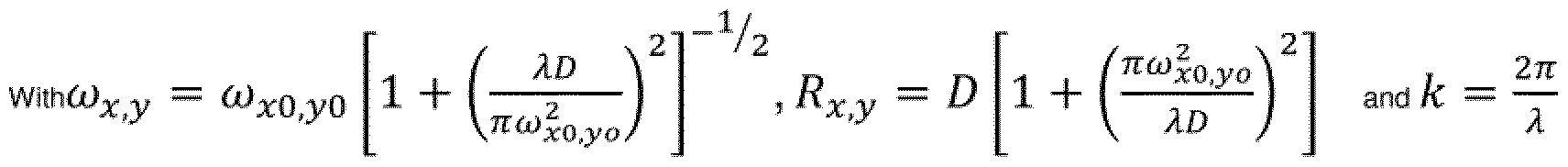

It is to be noted that the angular offset also adds to the change in intensity
measurement. It is, however, not given here for simplicity, in line with the laboratory experiment of EE234 Photonics Laboratory, Lab 4 (Laser to Fiber Coupling Carsten Langrock, John XJ Zhang, October 31, 2001). When the stylus is not in contact with the surface, the intensity detected is the reference intensity. When the stylus is in contact with the surface of the digitizer, the concave mirror, i.e. the reflective surface (12) is distorted due to the pressure applied by the user on the stylus tip (11). The change in intensity, as given by the above equations, and measured by the detector, is an indicator of the pressure applied. The detector measurement is relayed to the digitizer through wifi or Bluetooth communication, and a software application in the digitizer converts the change in intensity (pressure applied on the stylus) to the thickness of the stroke.
According to the present invention, the first embodiment of the invention takes advantage of the position measured by the digitizer, and thus the stylus is made pressure sensitive, using the change in optical fiber intensity. It is to be noted that the pressure sensitive optical fiber sensor, can be made with even one single optical fiber (as against the design described here, consisting of at least two fibers - one for transmitting laser from source to the reflector and the other for transmitting reflected light from the stylus head to the detector), which carries the light from the source, and the same fiber carries the reflected light from the reflecting surface.
In the second embodiment of the invention, the different intensity detected by the six fibers can be used to calculate the angular tilt of the stylus. The stroke of a stylus (when writing a character) is then traced continuously by monitoring the different intensity from the six different fibers. The second embodiment of the invention thus can be used across any computer system, with or without a digitizer. The position of the stylus, with respect to the display, can then be measured, using any of the existing technology (using linear accelerator or using modified fiber optic mouse).
Pressure sensitive styluses in the state of the art are either digitizer specific, or are not efficient when they are digitizer independent. The stylus proposed overcomes
these shortcomings, and can be used across all kind of digitizers (resistive, capacitive, inductive optic). Further, the use of optical fiber sensor ensures that the stylus does not suffer from electromagnetic interference (EMI). The use of intensity modulated optical fiber sensor ensures that the stylus has very high pressure sensitivity. The response time of the stylus is only constrained by the detector rise time, and the wireless transmission. Thus, the stylus proposed implements a fast and high pressure sensitive stylus that can be used across all digitizers and does not suffer from (EMI). To maximize the coupling of back-reflected light from a reflecting source, preferably, larger diameter fibers (~200pm) as against the standard fibers (~60pm) are used. Also, six fibers forming a hexagon, is used for carrying the light. Such groups of fibers are called probes and are also used in imaging devices such as endoscopes and spectroscopy. This hexagonal configuration of fibers carries more back reflected light than a single fiber configuration.
It is to be noted that a hexagon group of fibers is used for sensing the pressure of the stylus touch. Unlike most intensity based fiber sensors, which measure only the total intensity of the reflected light, and merely to maximize the reflected light, this embodiment advantageously utilizes the ratio of the light collected through each channel of the fiber group.
The present invention therefore presents a group of optical fibers housed in a tube which has a reflective stylus cap used for pressure sensitivity. The pressure sensitivity is defined as the pressure applied on the reflective stylus cap.
Direct measurement of pressure according to the present invention is easier and more precise results can be achieved. The reflective cap acts as a sensor itself such that it deforms as a kind of deformable mirror in the form of a reflecting surface.
The two principal embodiments according to the present invention comprises a first stylus having two fibers and a reflective cap to obtain a pressure sensitive stylus and
a second stylus having multiple fiber and a reflective cap so as to obtain a pressure sensitive angle-measuring stylus. The first one depends on the strength of the light captured, and the second one depends on the different strengths captured by different fibers.
Claims
Claims:
1) A pressure-sensitive stylus comprising a stylus tip (11) within the interior of which a fiber optic probe (13) is disposed, said fiber optic probe (13) comprising at least one optical fiber, said pressure-sensitive stylus further housing a light source, a detector and a wireless communication device for communicating with a digitizer, characterized in that;
the interior of the stylus tip (11) is hollow in the form of a cap with an inner concave surface (12) made of a reflective material, and said fiber optic probe (13) is attached to the focal point of said concave surface (12) such that the light from said light source is transmitted to said concave surface (12), being reflected thereof, and is coupled to said detector.
2) A pressure-sensitive stylus as set forth in Claim 1, wherein said concave surface (12) is made reflective through reflective metal coating.
3) A pressure-sensitive stylus as set forth in Claim 2, wherein said concave surface (12) is coated with aluminum. 4) A pressure-sensitive stylus as set forth in Claim 1, wherein said fiber optic probe (13) comprises two separate optical fibers.
5) A pressure-sensitive stylus as set forth in Claim 1, 2 or 3 wherein said fiber optic probe (13) consists of 6 optical fibers arranged hexagonally around a central optical fiber.
6) A pressure-sensitive stylus as set forth in Claim 5, wherein the far end of said central optical fiber is coupled to said light source such that the light from said central optical fiber is reflected from the concave surface (12), which is coupled back to said six hexagonal fibers, which are in turn coupled to said detector.
7) A pressure-sensitive stylus as set forth in Claim 1, 4, 5 or 6, wherein said detector is a photo-detector in the form of a CCD or CMOS sensor.
8) A pressure-sensitive stylus as set forth in Claim 1, 4, 5 or 6, wherein said light source is a LED. 9) A pressure-sensitive stylus as set forth in any previous Claims, wherein said stylus tip (11) is either detachable or fixed.
Priority Applications (2)
| Application Number | Priority Date | Filing Date | Title |
|---|---|---|---|
| PCT/EP2013/065988 WO2015014389A1 (en) | 2013-07-30 | 2013-07-30 | A pressure-sensitive stylus detecting intensity modulated light |
| EP13752854.3A EP3028124A1 (en) | 2013-07-30 | 2013-07-30 | A pressure-sensitive stylus detecting intensity modulated light |
Applications Claiming Priority (1)
| Application Number | Priority Date | Filing Date | Title |
|---|---|---|---|
| PCT/EP2013/065988 WO2015014389A1 (en) | 2013-07-30 | 2013-07-30 | A pressure-sensitive stylus detecting intensity modulated light |
Publications (1)
| Publication Number | Publication Date |
|---|---|
| WO2015014389A1 true WO2015014389A1 (en) | 2015-02-05 |
Family
ID=49034057
Family Applications (1)
| Application Number | Title | Priority Date | Filing Date |
|---|---|---|---|
| PCT/EP2013/065988 WO2015014389A1 (en) | 2013-07-30 | 2013-07-30 | A pressure-sensitive stylus detecting intensity modulated light |
Country Status (2)
| Country | Link |
|---|---|
| EP (1) | EP3028124A1 (en) |
| WO (1) | WO2015014389A1 (en) |
Cited By (2)
| Publication number | Priority date | Publication date | Assignee | Title |
|---|---|---|---|---|
| CN109700441A (en) * | 2018-12-29 | 2019-05-03 | 北京小成素问信息技术有限公司 | Detachable pen and the pulse diagnosis system of feeling the pulse |
| US10444866B2 (en) | 2016-11-14 | 2019-10-15 | Microsoft Technology Licensing, Llc | Force sensor for a stylus |
Citations (20)
| Publication number | Priority date | Publication date | Assignee | Title |
|---|---|---|---|---|
| US3937558A (en) | 1972-12-13 | 1976-02-10 | Nippon Glass Fiber Co., Ltd. | Optical fiber light pen |
| US4111052A (en) | 1977-08-29 | 1978-09-05 | Burroughs Corporation | Pressure-sensitive writing stylus |
| US4246439A (en) | 1978-04-10 | 1981-01-20 | U.S. Philips Corporation | Acoustic writing combination, comprising a stylus with an associated writing tablet |
| US4459022A (en) * | 1980-10-16 | 1984-07-10 | United Technologies Corporation | Fiber optic angular sensor |
| US4686332A (en) | 1986-06-26 | 1987-08-11 | International Business Machines Corporation | Combined finger touch and stylus detection system for use on the viewing surface of a visual display device |
| US4799751A (en) * | 1983-05-16 | 1989-01-24 | Gould Inc. | Detection device using fiber optic techniques |
| US4922236A (en) | 1988-04-25 | 1990-05-01 | Richard Heady | Fiber optical mouse |
| US5001306A (en) | 1990-02-16 | 1991-03-19 | Summagraphics Corporation | Distributed optical fiber device for digitizer tablet |
| US5007085A (en) | 1988-10-28 | 1991-04-09 | International Business Machines Corporation | Remotely sensed personal stylus |
| US5051736A (en) | 1989-06-28 | 1991-09-24 | International Business Machines Corporation | Optical stylus and passive digitizing tablet data input system |
| US5347295A (en) | 1990-10-31 | 1994-09-13 | Go Corporation | Control of a computer through a position-sensed stylus |
| US5488204A (en) | 1992-06-08 | 1996-01-30 | Synaptics, Incorporated | Paintbrush stylus for capacitive touch sensor pad |
| US5565632A (en) | 1995-02-20 | 1996-10-15 | Wacom Co., Ltd. | Pressure sensitive stylus pen |
| US5581052A (en) | 1993-10-18 | 1996-12-03 | Summagraphics Corporation | Pressure sensitive stylus having resiliently compressible tip element |
| US5633471A (en) | 1995-01-13 | 1997-05-27 | Wacom Co., Ltd. | Pressure sensitive element and a stylus pen with pressure sensitive function |
| US5652412A (en) | 1994-07-11 | 1997-07-29 | Sia Technology Corp. | Pen and paper information recording system |
| US5852434A (en) | 1992-04-03 | 1998-12-22 | Sekendur; Oral F. | Absolute optical position determination |
| US5914708A (en) | 1996-04-04 | 1999-06-22 | Cirque Corporation | Computer input stylus method and apparatus |
| WO1999031635A1 (en) * | 1997-12-16 | 1999-06-24 | Ran Shapira | Electronic pen |
| US5942733A (en) | 1992-06-08 | 1999-08-24 | Synaptics, Inc. | Stylus input capacitive touchpad sensor |
-
2013
- 2013-07-30 WO PCT/EP2013/065988 patent/WO2015014389A1/en active Application Filing
- 2013-07-30 EP EP13752854.3A patent/EP3028124A1/en not_active Withdrawn
Patent Citations (20)
| Publication number | Priority date | Publication date | Assignee | Title |
|---|---|---|---|---|
| US3937558A (en) | 1972-12-13 | 1976-02-10 | Nippon Glass Fiber Co., Ltd. | Optical fiber light pen |
| US4111052A (en) | 1977-08-29 | 1978-09-05 | Burroughs Corporation | Pressure-sensitive writing stylus |
| US4246439A (en) | 1978-04-10 | 1981-01-20 | U.S. Philips Corporation | Acoustic writing combination, comprising a stylus with an associated writing tablet |
| US4459022A (en) * | 1980-10-16 | 1984-07-10 | United Technologies Corporation | Fiber optic angular sensor |
| US4799751A (en) * | 1983-05-16 | 1989-01-24 | Gould Inc. | Detection device using fiber optic techniques |
| US4686332A (en) | 1986-06-26 | 1987-08-11 | International Business Machines Corporation | Combined finger touch and stylus detection system for use on the viewing surface of a visual display device |
| US4922236A (en) | 1988-04-25 | 1990-05-01 | Richard Heady | Fiber optical mouse |
| US5007085A (en) | 1988-10-28 | 1991-04-09 | International Business Machines Corporation | Remotely sensed personal stylus |
| US5051736A (en) | 1989-06-28 | 1991-09-24 | International Business Machines Corporation | Optical stylus and passive digitizing tablet data input system |
| US5001306A (en) | 1990-02-16 | 1991-03-19 | Summagraphics Corporation | Distributed optical fiber device for digitizer tablet |
| US5347295A (en) | 1990-10-31 | 1994-09-13 | Go Corporation | Control of a computer through a position-sensed stylus |
| US5852434A (en) | 1992-04-03 | 1998-12-22 | Sekendur; Oral F. | Absolute optical position determination |
| US5488204A (en) | 1992-06-08 | 1996-01-30 | Synaptics, Incorporated | Paintbrush stylus for capacitive touch sensor pad |
| US5942733A (en) | 1992-06-08 | 1999-08-24 | Synaptics, Inc. | Stylus input capacitive touchpad sensor |
| US5581052A (en) | 1993-10-18 | 1996-12-03 | Summagraphics Corporation | Pressure sensitive stylus having resiliently compressible tip element |
| US5652412A (en) | 1994-07-11 | 1997-07-29 | Sia Technology Corp. | Pen and paper information recording system |
| US5633471A (en) | 1995-01-13 | 1997-05-27 | Wacom Co., Ltd. | Pressure sensitive element and a stylus pen with pressure sensitive function |
| US5565632A (en) | 1995-02-20 | 1996-10-15 | Wacom Co., Ltd. | Pressure sensitive stylus pen |
| US5914708A (en) | 1996-04-04 | 1999-06-22 | Cirque Corporation | Computer input stylus method and apparatus |
| WO1999031635A1 (en) * | 1997-12-16 | 1999-06-24 | Ran Shapira | Electronic pen |
Non-Patent Citations (3)
| Title |
|---|
| CARSTEN LANGROCK ET AL: "EE234 Photonics Laboratory, Lab 4: Laser-to-Fiber Coupling", 31 October 2001 (2001-10-31), XP055101112, Retrieved from the Internet <URL:http://www.stanford.edu/~langrock/coursework/EE234_Lab_4.pdf> [retrieved on 20140210] * |
| JOHN XJ ZHANG, LASER TO FIBER COUPLING CARSTEN LANGROCK, 31 October 2001 (2001-10-31) |
| WOBBROCK, JACOB O.; BRAD A. MYERS; JOHN A. KEMBEL.: "Proceedings of the 16th annual ACM symposium on User interface software and technology", 2003, ACM, article "EdgeWrite: a stylus-based text entry method designed for high accuracy and stability of motion" |
Cited By (2)
| Publication number | Priority date | Publication date | Assignee | Title |
|---|---|---|---|---|
| US10444866B2 (en) | 2016-11-14 | 2019-10-15 | Microsoft Technology Licensing, Llc | Force sensor for a stylus |
| CN109700441A (en) * | 2018-12-29 | 2019-05-03 | 北京小成素问信息技术有限公司 | Detachable pen and the pulse diagnosis system of feeling the pulse |
Also Published As
| Publication number | Publication date |
|---|---|
| EP3028124A1 (en) | 2016-06-08 |
Similar Documents
| Publication | Publication Date | Title |
|---|---|---|
| US9841828B2 (en) | Pressure sensitive stylus | |
| EP3427133B1 (en) | Pen in field force sensing calibration | |
| US7839394B2 (en) | Electronic pen device | |
| US7646379B1 (en) | Wireless and contactless electronic input stylus having at least one button with optical scan and programmable pointer functionality | |
| KR100674090B1 (en) | System for Wearable General-Purpose 3-Dimensional Input | |
| JP2002049466A5 (en) | ||
| US20070109527A1 (en) | System and method for generating position information | |
| CN101398720B (en) | Pen interactive device | |
| CN108780369A (en) | The soft touch detection of stylus | |
| KR20160021808A (en) | Electronic pen | |
| CN102736753B (en) | Photoelectric touch pen system | |
| US11893169B2 (en) | Multi-functional stylus | |
| CN101344374B (en) | Texture measuring apparatus and method | |
| EP3028124A1 (en) | A pressure-sensitive stylus detecting intensity modulated light | |
| KR20100033076A (en) | Touch screen with touch pressure sensing function | |
| WO2007046604A1 (en) | Device for inputting digital information | |
| KR20070042858A (en) | Digital input device with pen-type | |
| US9170685B2 (en) | Object location determination | |
| WO2016204675A1 (en) | A stylus with a deformable stylus tip | |
| TWI461971B (en) | Pressure-sensitive cursor control device | |
| EP2787417B1 (en) | Multi-control stylus | |
| CN109932113B (en) | Chirped fiber grating measuring system with ultrahigh spatial resolution for force touch | |
| CN110285912A (en) | A kind of pressure sensitive signal supervisory instrument | |
| KR101673135B1 (en) | Digitizer system | |
| Wang | Tactile Sensing with Optical Mouse Sensor |
Legal Events
| Date | Code | Title | Description |
|---|---|---|---|
| WWE | Wipo information: entry into national phase |
Ref document number: 2014/16244 Country of ref document: TR |
|
| 121 | Ep: the epo has been informed by wipo that ep was designated in this application |
Ref document number: 13752854 Country of ref document: EP Kind code of ref document: A1 |
|
| NENP | Non-entry into the national phase |
Ref country code: DE |
|
| WWE | Wipo information: entry into national phase |
Ref document number: 2013752854 Country of ref document: EP |