WO2015129828A1 - Display light projection optical device - Google Patents
Display light projection optical device Download PDFInfo
- Publication number
- WO2015129828A1 WO2015129828A1 PCT/JP2015/055711 JP2015055711W WO2015129828A1 WO 2015129828 A1 WO2015129828 A1 WO 2015129828A1 JP 2015055711 W JP2015055711 W JP 2015055711W WO 2015129828 A1 WO2015129828 A1 WO 2015129828A1
- Authority
- WO
- WIPO (PCT)
- Prior art keywords
- display light
- optical device
- fresnel
- optical member
- optical
- Prior art date
Links
- 230000003287 optical effect Effects 0.000 title claims abstract description 171
- 239000000945 filler Substances 0.000 claims abstract description 4
- 230000015572 biosynthetic process Effects 0.000 claims description 7
- 239000005340 laminated glass Substances 0.000 claims description 4
- 239000010410 layer Substances 0.000 description 59
- 239000000463 material Substances 0.000 description 9
- 230000005540 biological transmission Effects 0.000 description 8
- 239000000565 sealant Substances 0.000 description 8
- 230000001788 irregular Effects 0.000 description 5
- 230000004048 modification Effects 0.000 description 5
- 238000012986 modification Methods 0.000 description 5
- 239000011247 coating layer Substances 0.000 description 4
- 239000011347 resin Substances 0.000 description 3
- 229920005989 resin Polymers 0.000 description 3
- 230000000694 effects Effects 0.000 description 2
- 239000005357 flat glass Substances 0.000 description 2
- 239000011521 glass Substances 0.000 description 2
- 229920003229 poly(methyl methacrylate) Polymers 0.000 description 2
- 239000004926 polymethyl methacrylate Substances 0.000 description 2
- 239000012780 transparent material Substances 0.000 description 2
- 230000002411 adverse Effects 0.000 description 1
- 239000003795 chemical substances by application Substances 0.000 description 1
- 238000000151 deposition Methods 0.000 description 1
- 239000008393 encapsulating agent Substances 0.000 description 1
- 238000007496 glass forming Methods 0.000 description 1
- 210000003128 head Anatomy 0.000 description 1
- 238000005286 illumination Methods 0.000 description 1
- 238000003384 imaging method Methods 0.000 description 1
- 239000004973 liquid crystal related substance Substances 0.000 description 1
- 238000004519 manufacturing process Methods 0.000 description 1
- 239000002184 metal Substances 0.000 description 1
- 238000007789 sealing Methods 0.000 description 1
- 238000004611 spectroscopical analysis Methods 0.000 description 1
- 238000003786 synthesis reaction Methods 0.000 description 1
- 239000010409 thin film Substances 0.000 description 1
- 238000002834 transmittance Methods 0.000 description 1
- 238000007740 vapor deposition Methods 0.000 description 1
Images


Classifications
-
- G—PHYSICS
- G02—OPTICS
- G02B—OPTICAL ELEMENTS, SYSTEMS OR APPARATUS
- G02B27/00—Optical systems or apparatus not provided for by any of the groups G02B1/00 - G02B26/00, G02B30/00
- G02B27/01—Head-up displays
- G02B27/0101—Head-up displays characterised by optical features
-
- B—PERFORMING OPERATIONS; TRANSPORTING
- B60—VEHICLES IN GENERAL
- B60K—ARRANGEMENT OR MOUNTING OF PROPULSION UNITS OR OF TRANSMISSIONS IN VEHICLES; ARRANGEMENT OR MOUNTING OF PLURAL DIVERSE PRIME-MOVERS IN VEHICLES; AUXILIARY DRIVES FOR VEHICLES; INSTRUMENTATION OR DASHBOARDS FOR VEHICLES; ARRANGEMENTS IN CONNECTION WITH COOLING, AIR INTAKE, GAS EXHAUST OR FUEL SUPPLY OF PROPULSION UNITS IN VEHICLES
- B60K35/00—Arrangement of adaptations of instruments
-
- B60K35/23—
-
- G—PHYSICS
- G02—OPTICS
- G02B—OPTICAL ELEMENTS, SYSTEMS OR APPARATUS
- G02B1/00—Optical elements characterised by the material of which they are made; Optical coatings for optical elements
- G02B1/10—Optical coatings produced by application to, or surface treatment of, optical elements
- G02B1/11—Anti-reflection coatings
-
- G—PHYSICS
- G02—OPTICS
- G02B—OPTICAL ELEMENTS, SYSTEMS OR APPARATUS
- G02B27/00—Optical systems or apparatus not provided for by any of the groups G02B1/00 - G02B26/00, G02B30/00
- G02B27/0018—Optical systems or apparatus not provided for by any of the groups G02B1/00 - G02B26/00, G02B30/00 with means for preventing ghost images
-
- G—PHYSICS
- G02—OPTICS
- G02B—OPTICAL ELEMENTS, SYSTEMS OR APPARATUS
- G02B27/00—Optical systems or apparatus not provided for by any of the groups G02B1/00 - G02B26/00, G02B30/00
- G02B27/01—Head-up displays
-
- G—PHYSICS
- G02—OPTICS
- G02B—OPTICAL ELEMENTS, SYSTEMS OR APPARATUS
- G02B3/00—Simple or compound lenses
- G02B3/02—Simple or compound lenses with non-spherical faces
- G02B3/08—Simple or compound lenses with non-spherical faces with discontinuous faces, e.g. Fresnel lens
-
- G—PHYSICS
- G02—OPTICS
- G02B—OPTICAL ELEMENTS, SYSTEMS OR APPARATUS
- G02B5/00—Optical elements other than lenses
- G02B5/08—Mirrors
-
- B60K2360/20—
-
- B60K2360/334—
-
- G—PHYSICS
- G02—OPTICS
- G02B—OPTICAL ELEMENTS, SYSTEMS OR APPARATUS
- G02B27/00—Optical systems or apparatus not provided for by any of the groups G02B1/00 - G02B26/00, G02B30/00
- G02B27/01—Head-up displays
- G02B27/0101—Head-up displays characterised by optical features
- G02B2027/0118—Head-up displays characterised by optical features comprising devices for improving the contrast of the display / brillance control visibility
- G02B2027/012—Head-up displays characterised by optical features comprising devices for improving the contrast of the display / brillance control visibility comprising devices for attenuating parasitic image effects
-
- G—PHYSICS
- G02—OPTICS
- G02B—OPTICAL ELEMENTS, SYSTEMS OR APPARATUS
- G02B27/00—Optical systems or apparatus not provided for by any of the groups G02B1/00 - G02B26/00, G02B30/00
- G02B27/01—Head-up displays
- G02B27/0101—Head-up displays characterised by optical features
- G02B2027/013—Head-up displays characterised by optical features comprising a combiner of particular shape, e.g. curvature
-
- G—PHYSICS
- G02—OPTICS
- G02B—OPTICAL ELEMENTS, SYSTEMS OR APPARATUS
- G02B27/00—Optical systems or apparatus not provided for by any of the groups G02B1/00 - G02B26/00, G02B30/00
- G02B27/01—Head-up displays
- G02B2027/0192—Supplementary details
- G02B2027/0194—Supplementary details with combiner of laminated type, for optical or mechanical aspects
Definitions
- the present invention is a display light projection that reflects display light emitted from a display unit in the vicinity of one surface and projects it on a predetermined eye point, and transmits extraneous light incident on the other surface in the thickness direction.
- the present invention relates to an optical device.
- HUD Head Up Display
- a light image including various information to be displayed is reflected from the HUD device to a windshield (front window glass) or a reflector called a combiner.
- the light path is formed so that the light reflected on the windshield or the like is reflected in the direction of the driver's viewpoint. Therefore, the driver can visually recognize the HUD visible display information reflected on the windshield or the like as a virtual image while simultaneously viewing the scenery in front of the vehicle through the windshield. That is, the driver can visually recognize various information by displaying the HUD without moving the line of sight while maintaining the normal driving state.
- Patent Document 1 discloses that a special optical element (corresponding to the combiner) is attached to the glass surface of the windshield.
- the light emitted from the HUD is reflected by the surface of the optical element on the windshield and travels in the direction of the driver's viewpoint.
- the optical element is made of a material that transmits visible light, the driver can display images such as scenery in front of the vehicle in addition to the display image formed as a virtual image in front of the optical element. It can be visually recognized in a state of being transmitted through the optical element.
- Patent Document 1 discloses that a magnifying optical system is formed by providing a Fresnel lens on an optical element. This makes it possible to reduce the size of the HUD. Further, since the Fresnel lens is used, the thickness of the optical element can be reduced.
- Patent Document 1 has the following problems.
- An image such as a landscape in front of the vehicle passes through the optical element in the thickness direction and reaches the position of the eyes of the driver.
- the surface close to the driver of the optical element has a concavo-convex shape of the Fresnel lens, and the surface of the concavo-convex shape and the air layer are in direct contact with each other, the optical characteristics are changed by the change in the refractive index at this boundary surface. appear.
- the transmission / reflection optical layer 15 is disposed at a position adjacent to the uneven surface of the Fresnel lens.
- the refractive index of the material of the Fresnel lens and the refractive index of the material of the transmission / reflection optical layer 15 are different.
- the present invention has been made in view of the above-described circumstances, and an object thereof is to have a reflective surface that can be used for projection of an HUD device and an optical enlargement function, and to obtain good transmission visibility.
- An object of the present invention is to provide an optical device for projecting display light.
- an optical device for projecting display light is characterized by the following (1) to (8).
- Display light projected from the display unit is reflected in the vicinity of one surface and projected onto a predetermined eye point, and the display light has a property of transmitting extraneous light incident on the other surface in the thickness direction.
- An optical device A transparent first optical member formed in a thin plate shape; A Fresnel-shaped portion composed of a plurality of grooves formed concentrically on one surface in the thickness direction of the first optical member; A half mirror layer formed on the surface of the Fresnel-shaped portion; A second optical member composed of a transparent filler for filling the irregularities on the surface of the half mirror layer to form a flat surface; A transparent thin plate-like third optical member for protecting the outer surface of the second optical member; With The refractive index of the first optical member, the refractive index of the second optical member, and the refractive index of the third optical member are substantially the same.
- Optical device for display light projection A transparent first optical member formed in a thin plate shape
- a Fresnel-shaped portion composed of a plurality of grooves formed concentrically on one surface in the thickness direction of the first optical member
- a half mirror layer formed on the surface of the Fresnel-shaped portion
- a second optical member composed of a transparent filler for fill
- An optical device for projecting display light configured as described in (1) above An antireflection layer is formed on each of the surface exposed to the outside of the first optical member and the surface exposed to the outside of the third optical member. Optical device for display light projection.
- An optical device for projecting display light according to any one of (1) to (4) above, The arrangement state of the Fresnel-shaped part or the target position of the display light is determined so that the optical axis of the light incident on the half mirror layer from the display unit deviates from the center of the concentric circle of the Fresnel-shaped part. , Optical device for display light projection.
- a display light projection optical device having any one of the constitutions (1) to (5), A spherical surface in which the overall shape of the first optical member and the shape of the Fresnel-shaped portion have a curved surface shape that matches the shape of a windshield of a vehicle, and the curvature of the surface of the Fresnel-shaped portion is represented by a constant radius. Or determined according to an aspheric surface represented by a polynomial, Optical device for display light projection.
- the display light projection optical device having the configuration (1) the display light emitted from the display unit is reflected by the surface of the half mirror layer and travels toward the driver's eye point.
- extraneous light incident from the front of the vehicle passes through the display light projection optical device and travels toward the eye point.
- the half mirror layer is formed on the surface of the Fresnel-shaped portion, an expansion optical system is formed for the reflected light.
- the light transmitted through the display light projection optical device has the same refractive index of the first optical member, the second optical member, and the third optical member, so that refraction occurs at the boundary between these surfaces. Absent.
- the light transmitted through the optical device for projecting display light should be visually recognized as an image with the same magnification as in a normal scene viewed through the windshield. Can do.
- the display light projecting optical device having the configuration (2) it is possible to prevent the generation of a ghost image having the same magnification and the halation due to the internal irregular reflection by the action of the light reflection preventing layer.
- the display light projection optical device having the configuration (3) the transmitted light travels toward the driver's eye point with almost no attenuation at the half mirror layer. Therefore, it is possible to improve the visibility when the driver visually recognizes the scene in front through the display light projection optical device.
- the wavelength band of the display light can be narrowed by using a scanner capable of emitting one or a plurality of laser beams such as R, G, B, etc. as the light source of the display unit.
- the display light can be efficiently reflected by the half mirror layer having.
- the optical device for projecting display light having the configuration (4) since it is incorporated inside the windshield for a vehicle, the surface of the windshield can be maintained in a flat state, and the driver feels uncomfortable.
- the display light can be projected without giving.
- the display light projection optical device having the configuration (5) it is possible to reduce the influence of the double image ghost generated by the synthesis of the enlarged image and the equal magnification image.
- the display image visually recognized by the driver in addition to the magnified image formed by reflection by the half mirror layer, the same size image that is reflected by the front surface or the back surface of the display light projection optical device is received. Since it is included, a double image ghost may be visually recognized.
- the display light projecting optical device having the configuration (6) since the curved surface shape is formed in accordance with the shape of the windshield of the vehicle, the display quality when the driver visually recognizes the HUD display is optimized.
- the display light projecting optical device having the configuration of (7) above it is possible to ensure the minimum necessary resolution according to the display capability of the display unit, and furthermore, spectroscopy (rainbow color) due to diffraction at the Fresnel edge portion. And ghosts such as double images can be prevented, and flare image generation due to irregular reflection can be reduced.
- the optical device for projecting display light having the configuration of (8) above since reflection of light at the standing wall region is suppressed, normal light transmission and unintentional light generation through an optical path other than one-time reflection are generated. Is minimized, and flare image generation can be suppressed.
- the optical device for projecting display light of the present invention has a reflective surface that can be used for projection of the HUD device and an optical enlargement function, and can obtain better transmission visibility than before. Is possible.
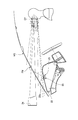
- FIG. 1 is a perspective view of the vicinity of a windshield of a vehicle equipped with an optical device for projecting display light as viewed from the vehicle interior side.
- FIG. 2 is a longitudinal sectional view of the same vehicle as FIG. 1 viewed from the side.
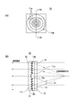
- FIG. 3A is a front view showing the display light projection optical device of the embodiment, and
- FIG. 3B is a partially enlarged cross-sectional view taken along line IIIB-IIIB in FIG.
- FIG. 4 is a longitudinal sectional view showing the arrangement state of the display light projection optical device and the positional relationship between the optical axis and the eye point of the display device.
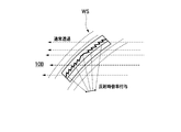
- FIG. 5 is a longitudinal sectional view showing the shape of the display light projecting optical device according to the modification.
- FIG. 1 shows a state in which the vicinity of a windshield WS of a vehicle equipped with the display light projection optical device of the embodiment is viewed obliquely from the passenger compartment. Moreover, the arrangement
- the display light projection optical device of the embodiment is incorporated as an intermediate layer in a windshield WS (window glass) of a vehicle configured as a laminated glass.
- a Fresnel mirror region FM is formed in the display light projection optical device.
- the Fresnel mirror region FM basically has a half-mirror function, and light incident on the Fresnel mirror region FM from the vehicle interior side is reflected, and enters the Fresnel mirror region FM in the right direction in FIG. Incident light has the property of transmitting.
- the Fresnel mirror region FM includes a Fresnel lens and forms a magnifying optical system. A specific configuration of the display light projection optical device will be described in detail later.
- a HUD (head-up display) unit 20 is disposed below a dashboard 22 in front of the meter unit 21.
- the HUD unit 20 includes a flat panel display such as a transmissive liquid crystal panel and a light source (backlight) for illumination.
- a flat panel display such as a transmissive liquid crystal panel and a light source (backlight) for illumination.
- various information useful for driving such as vehicle speed is displayed as visible information such as letters, numbers, and symbols as necessary.
- display light including an image of the displayed visible information can be emitted from the HUD unit 20.
- a rectangular opening 22 a is formed at a location of the dashboard 22 above the HUD unit 20.
- the display light emitted from the HUD unit 20 travels to the upper windshield WS via the opening 22a.
- the above-described Fresnel mirror region FM is disposed at a location where display light from the HUD unit 20 of the windshield WS is incident.
- the display light emitted from the HUD unit 20 is incident on the surface of the windshield WS, reflected by the Fresnel mirror region FM, and reaches the eye point EP corresponding to the assumed driver's eye position. Since this display light is reflected by the Fresnel mirror region FM, the display image visually recognized by the driver is displayed as a virtual image as if it is displayed on the virtual image imaging plane 24 in front of the windshield WS (for example, 10 m ahead). Imaged. Further, since the Fresnel mirror area FM transmits light incident from the front of the vehicle toward the vehicle interior, like the windshield WS, the driver can also visually recognize the scene in front of the vehicle through the Fresnel mirror area FM. . That is, the scene in front of the vehicle and the display image displayed by the HUD unit 20 can be visually recognized simultaneously.
- the thickness can be reduced and it can be incorporated into the windshield WS. Further, since the Fresnel mirror region FM forms the magnifying optical system, it is not necessary to incorporate the magnifying optical system in the HUD unit 20. Further, the opening area of the opening 22a can be reduced as compared with the case where the magnifying optical system is built in the HUD unit 20.
- a louver 23 is disposed in the vicinity of the opening 22a.
- the louver 23 has a function of suppressing unnecessary external light from being reflected near the opening 22a and directed toward the eye point EP, thereby improving the visibility of the HUD display.
- FIG. 3A is a front view showing the display light projection optical device of the embodiment
- FIG. 3B is a partially enlarged cross-sectional view taken along line IIIB-IIIB in FIG.
- the display light projecting optical device is configured as a combiner 10 for projecting the display light of the HUD unit 20.
- the combiner 10 has a rectangular shape as shown in FIG. 3A, and is formed in a size larger than the Fresnel mirror region FM shown in FIG. Note that the size of the combiner 10 and the Fresnel mirror region FM is not limited to this relationship. Depending on the specifications applied to these, the size can be designed as appropriate.
- the combiner 10 is composed of a plurality of layers stacked in the thickness direction. Specifically, the combiner 10 includes a Fresnel lens 11, a half mirror layer 12, a sealant layer 13, a transparent plate 14, and AR coating layers 15 and 16.
- the Fresnel lens 11 is formed in a thin plate shape with a material such as a transparent resin (for example, polymethyl methacrylate resin: PMMA) having a known refractive index (n1) and glass. Further, the Fresnel lens 11 has a Fresnel-shaped portion 11a formed on one surface in the thickness direction, and the other surface is a flat surface 11c.
- a transparent resin for example, polymethyl methacrylate resin: PMMA
- the Fresnel-shaped portion 11a has a large number of grooves formed concentrically from the central portion of the Fresnel lens 11, and protrudes between adjacent grooves. Therefore, in the cross section shown in FIG. 3B, the Fresnel-shaped portion 11a has a sawtooth surface shape. This surface shape forms a lens optically.
- the formation pitch (Fresnel pitch) P of the grooves or protrusions in the Fresnel shape portion 11a will be described later.
- a half mirror layer 12 is formed on the surface of the Fresnel-shaped portion 11 a of the Fresnel lens 11. Specifically, the half mirror layer 12 is formed by vapor-depositing a metal or inorganic multilayer thin film on the surface. In the present embodiment, the light reflectance of the half mirror layer 12 is 20%. The thickness of the half mirror layer 12 to be formed is less than 100 [nm].
- the location of the Fresnel standing wall 11b of the Fresnel-shaped portion 11a is excluded from the vapor deposition target. That is, the half mirror layer 12 is formed on the entire surface excluding the region of the Fresnel standing wall 11b extending in the direction parallel to the thickness direction at each boundary of the plurality of grooves of the Fresnel-shaped portion 11a.
- the half mirror layer 12 since the half mirror layer 12 does not exist at the location of the Fresnel standing wall 11b, reflection on the Fresnel standing wall 11b that takes an optical path other than normal transmission and single reflection is suppressed, and unintended light generation due to this reflection occurs. Is minimized. Thereby, generation
- the sealant layer 13 is provided in order to cover the unevenness of the Fresnel-shaped portion 11a of the Fresnel lens 11 to make a flat surface.
- the sealant layer 13 is formed by filling and curing a transparent material such as an ultraviolet (UV) curable resin.
- the material forming the encapsulant layer 13 is limited to a material having a refractive index (n3) substantially the same as that of the Fresnel lens 11.
- One surface 13a in the thickness direction of the sealant layer 13 is flat, and the surface 13b in close contact with the Fresnel-shaped portion 11a and the half mirror layer 12 is formed in a surface shape that complements the irregularities of the Fresnel-shaped portion 11a.
- the transparent plate 14 is provided to protect the surface of the combiner 10.
- the transparent plate 14 is made of a transparent material having a refractive index (n2) substantially the same as that of the Fresnel lens 11, and is formed in a thin plate shape.
- AR (Anti Reflection) coating layers 15 and 16 are formed on the two outer surfaces in the thickness direction of the combiner 10, respectively. Therefore, it can suppress that the light which injects into the combiner 10 from the outer side, and the light radiate
- the combiner 10 shown in FIGS. 3 (A) and 3 (B) is incorporated and integrated as an intermediate layer in the windshield WS in the example shown in FIGS. 1 and 2. That is, the half mirror layer 12 of the combiner 10 forms the Fresnel mirror region FM shown in FIGS. Further, since the half mirror layer 12 forms a Fresnel mirror having an optical magnification according to the shape of the Fresnel-shaped portion 11a, a magnifying optical system is formed for light incident from the HUD unit 20. Thereby, a virtual image can be formed in the position (virtual image formation surface 24) where the distance ahead of windshield WS was separated.
- the combiner 10 is integrated with the windshield WS. However, the combiner 10 is inclined at a position different from the windshield WS, for example, on the dashboard 22. It may be arranged.
- the refractive index (n1) of the material of the Fresnel lens 11, the refractive index (n2) of the material of the transparent plate 14, and the sealant layer 13 The refractive index (n3) of all the materials is the same. Therefore, light refraction due to the difference in refractive index can be prevented at the boundary between the Fresnel lens 11 and the sealant layer 13 and at the boundary between the sealant layer 13 and the transparent plate 14.
- the combiner 10 having the magnifying optical system using the Fresnel lens 11 on the windshield WS or in the vicinity thereof, a virtual image with a wide viewing angle can be displayed on the HUD unit 20.
- the HUD unit 20 can be miniaturized and the area of the opening 22a can be reduced.
- the formation pitch of the plurality of grooves in the Fresnel-shaped portion 11a is determined to be an approximate value of the following expression or a value smaller than that.
- P (tan ⁇ ⁇ D) / Pixel (1)
- ⁇ Display angle of view
- D Distance between the assumed eye point and the Fresnel shape portion
- Pixel Number of vertical or horizontal pixels on the display screen of the HUD unit 20
- the Fresnel pitch P of the Fresnel shape portion 11a By determining the Fresnel pitch P of the Fresnel shape portion 11a in this way, the minimum necessary dot pixel display capability required by the HUD unit 20 can be ensured for the display image visually recognized by the driver at the eye point EP. . Further, it is possible to prevent spectroscopic (rainbow color generation) due to diffraction at the Fresnel edge portion and ghosts such as double images, and to reduce flare image generation due to irregular reflection.
- the combiner 10 shown in FIG. 3B is configured such that the half mirror layer 12 includes the function of a band stop filter. That is, a characteristic is formed such that the light reflection characteristic of the half mirror layer 12 changes according to the difference in wavelength.
- the laser light when a laser light source is used as the light source of the display light incident on the combiner 10, the laser light is emitted only in a very narrow wavelength band, so that only the wavelength band of the laser light is reflected and light having other wavelengths is reflected.
- the half mirror layer 12 has a band stop filter characteristic that transmits all of the light. Therefore, extraneous light other than the wavelength band of the laser light can be transmitted through the half mirror layer 12 with almost no attenuation. Therefore, even when the driver visually recognizes the scene in front of the vehicle via the Fresnel mirror region FM, since the transmittance of the combiner 10 is high, it can be visually recognized in a bright state as in regions other than the Fresnel mirror region FM. .
- the half mirror layer 12 is provided with a band stop filter characteristic that reflects light for each of the R wavelength band, the G wavelength band, and the B wavelength band.
- each region on the display surface is sequentially scanned left and right and up and down using a laser scanner to uniformly illuminate the entire rectangular region and form display light. can do.
- FIG. 4 shows the arrangement state of the combiner 10 (optical device for projecting display light) and the positional relationship between the optical axis and the eye point of the display device.
- the optical axis A1 of the light emitted from the HUD unit 20 is configured to coincide with the center of the combiner 10, that is, the Fresnel center FC of the Fresnel lens 11 as shown in FIG.
- the display image of the HUD unit 20 is reflected by the half mirror layer 12 so as to be visible at the position of the eye point EP1 facing the Fresnel center FC.
- the light emitted from the HUD unit 20 is positioned so as to move to a position offset from the Fresnel center FC as shown by the optical axis A2 in FIG.
- the display image of the HUD unit 20 is reflected at a position shifted upward from the Fresnel center FC and formed so as to be visible at the eye point EP2.
- the display image visually recognized by the eye point EP may include an unnecessary image that is reflected by the front or back surface of the combiner 10 and reaches the eye point EP. Thus, this may cause a double image ghost to be seen.
- the optical path of the display image is shifted from the Fresnel center FC as in the optical axis A2 shown in FIG. 4, the magnified image reflected by the half mirror layer 12 and the same magnification reflected by the front or back surface of the combiner 10 are used. The optical path difference from the image becomes large and the double image ghost becomes difficult to see.
- FIG. 5 shows a cross-sectional shape of a combiner 10B (optical device for projecting display light) in this modification.
- the shape of the combiner is curved like the combiner 10B shown in FIG. 5 in order to optimize the HUD display quality. It is desirable to change the shape.
- a spherical surface represented by a certain radius (R) according to the curved surface shape unique to the windshield WS, or It is determined according to an aspheric surface represented by a polynomial.
- the HUD display quality is improved, and even when viewing the front field of view through the Fresnel mirror region FM, it is possible to ensure the same transmission visibility as when viewing through the normal windshield WS. it can.
- An optical device for projecting display light having the following characteristics: A transparent first optical member (Fresnel lens 11) formed in a thin plate shape; A Fresnel-shaped portion (11a) composed of a plurality of grooves formed concentrically on one surface in the thickness direction of the first optical member; A half mirror layer (12) formed on the surface of the Fresnel-shaped portion; A second optical member (sealing agent layer 13) composed of a transparent filler for filling the irregularities on the surface of the half mirror layer to form a flat surface; A transparent thin plate-shaped third optical member (transparent plate 14) that protects the outer surface of the second optical member; With The refractive index of the first optical member, the refractive index of the second optical member, and the refractive index of the third optical member are substantially the same.
- Optical device for display light projection (combiner 10).
- Optical device for display light projection (3) An optical device for projecting display light configured as described in (1) or (2) above, The half mirror layer functions as a band stop filter that reflects only a specific wavelength component, Optical device for display light projection.
- WS windshield for vehicles
- An optical device for projecting display light according to any one of (1) to (4) above, The arrangement state of the Fresnel-shaped portion, or the display light of the display light so that the optical axis (A2) of light incident on the half mirror layer from the display unit deviates from the center of the concentric circle (Fresnel FC) of the Fresnel-shaped portion.
- the incident target position is defined, Optical device for display light projection.
- a display light projection optical device having any one of the constitutions (1) to (5), A spherical surface in which the overall shape of the first optical member and the shape of the Fresnel-shaped portion have a curved surface shape that matches the shape of a windshield of a vehicle, and the curvature of the surface of the Fresnel-shaped portion is represented by a constant radius. Or determined according to an aspheric surface represented by a polynomial, Optical device for display light projection (combiner 10B).
- the present invention there is an effect that a reflective surface that can be used for projection of the HUD device and an optical enlargement function can be obtained, and good transmission visibility can be obtained.
- the present invention that exhibits this effect is characterized in that the display light emitted from the display unit is reflected in the vicinity of one surface and projected onto a predetermined eye point, and the external light incident on the other surface is transmitted in the thickness direction.
- the present invention is useful for an optical device for projecting display light.
Abstract
This display light projection optical device is provided with a transparent first optical member (11) which is formed as a thin plate, Fresnel-shape portion (11a) which is formed in a concentric manner on one surface of the first optical member in the thickness direction, a half-mirror layer (12) which is formed on the surface of the Fresnel-shaped unit, a second optical member (13) which is configured with a transparent filler which fills in unevenness on the surface of the half-mirror layer to form a flat surface, and a transparent, thin plate-shape third optical member (14) which protects the outside surface of the second optical member. The refractive index of the first optical member, the refractive index of the second optical member and the refractive index of the third optical member are the same.
Description
本発明は、表示ユニットから出射される表示光を一方の面の近傍で反射して所定のアイポイントに投影し、他方の面に入射した外来光を厚み方向に透過する特性を有する表示光投影用光学デバイスに関する。
The present invention is a display light projection that reflects display light emitted from a display unit in the vicinity of one surface and projects it on a predetermined eye point, and transmits extraneous light incident on the other surface in the thickness direction. The present invention relates to an optical device.
一般的な車両用のヘッドアップディスプレイ(HUD:Head Up Display)装置においては、表示すべき様々な情報を含む光の像をHUD装置からウインドシールド(前方の窓ガラス)、又はコンバイナと呼ばれる反射板に投影し、ウインドシールド等で反射した光が運転者の視点の方向に向かうように光路を形成する。したがって、運転者は、ウインドシールドを通して車両の前方の風景を視認しながら、同時にウインドシールド等に映るHUDの可視表示情報を虚像として視認することができる。つまり、運転者は通常の運転状態を維持したまま、視線を移動することなしに様々な情報をHUDの表示により視認することができる。
In a general vehicle head-up display (HUD: Head Up Display) device, a light image including various information to be displayed is reflected from the HUD device to a windshield (front window glass) or a reflector called a combiner. The light path is formed so that the light reflected on the windshield or the like is reflected in the direction of the driver's viewpoint. Therefore, the driver can visually recognize the HUD visible display information reflected on the windshield or the like as a virtual image while simultaneously viewing the scenery in front of the vehicle through the windshield. That is, the driver can visually recognize various information by displaying the HUD without moving the line of sight while maintaining the normal driving state.
特許文献1には、ウインドシールドのガラス面に特別な光学素子(前記コンバイナに相当)を貼り付けることが開示されている。HUDから出射した光は、ウインドシールド上の光学素子の面で反射して運転者の視点の方向に向かう。また、光学素子は可視光を透過する材料で構成されているので、運転者は光学素子の前方に虚像として結像される表示像の他に、車両前方の風景等の像も、ウインドシールド及び光学素子を透過した状態で視認することができる。
Patent Document 1 discloses that a special optical element (corresponding to the combiner) is attached to the glass surface of the windshield. The light emitted from the HUD is reflected by the surface of the optical element on the windshield and travels in the direction of the driver's viewpoint. In addition, since the optical element is made of a material that transmits visible light, the driver can display images such as scenery in front of the vehicle in addition to the display image formed as a virtual image in front of the optical element. It can be visually recognized in a state of being transmitted through the optical element.
また、特許文献1には、光学素子上にフレネルレンズを設けて拡大光学系を形成することが開示されている。これにより、HUDを小型化することが可能になる。また、フレネルレンズを利用しているので、光学素子の厚みを薄くすることができる。
Patent Document 1 discloses that a magnifying optical system is formed by providing a Fresnel lens on an optical element. This makes it possible to reduce the size of the HUD. Further, since the Fresnel lens is used, the thickness of the optical element can be reduced.
しかしながら、特許文献1の光学素子については、次に説明するような課題がある。車両前方の風景等の像は、光学素子を厚み方向に透過して運転者の目の位置に到達する。ところが、光学素子の運転者に近い側の面にはフレネルレンズの凹凸形状があり、この凹凸形状の面と空気層とが直接触れているので、この境界面における屈折率の変化により光学特性が表れる。
However, the optical element of Patent Document 1 has the following problems. An image such as a landscape in front of the vehicle passes through the optical element in the thickness direction and reaches the position of the eyes of the driver. However, since the surface close to the driver of the optical element has a concavo-convex shape of the Fresnel lens, and the surface of the concavo-convex shape and the air layer are in direct contact with each other, the optical characteristics are changed by the change in the refractive index at this boundary surface. appear.
つまり、車両前方の風景等の像が光学素子を透過して光学素子から運転者側に出射する際にもフレネルレンズの光学倍率の影響を受けることになる。したがって、運転者が前方視界を視認する際に、ウインドシールド上の様々な領域のうち、光学素子が配置されている箇所だけについては、フレネルレンズの影響で局部的に拡大又は縮小されたり、歪みや乱反射の影響を受ける状態で視認することになる。したがって、前方視界を視認しにくい領域が前記光学素子によりウインドシールド上に形成されてしまい、運転に悪影響を及ぼす可能性がある。
That is, when an image such as a landscape in front of the vehicle passes through the optical element and is emitted from the optical element to the driver side, it is also affected by the optical magnification of the Fresnel lens. Therefore, when the driver visually recognizes the front field of view, only the portion where the optical element is arranged in various regions on the windshield is locally enlarged or reduced due to the influence of the Fresnel lens, or is distorted. And will be visually recognized in the state of being affected by diffuse reflection. Therefore, a region where it is difficult to visually recognize the front field of view is formed on the windshield by the optical element, which may adversely affect driving.
また、特許文献1の図7に示された構成では、フレネルレンズの凹凸形状面と隣接する位置に透過反射光学層15が配置されている。しかし、図7の構成においても、フレネルレンズの材料の屈折率と透過反射光学層15の材料の屈折率とが異なっているので、これらを一体化した部品全体として光学的な倍率を相殺できたとしても、内部乱反射の影響によりハレーション等が生じる可能性が高い。
Further, in the configuration shown in FIG. 7 of Patent Document 1, the transmission / reflection optical layer 15 is disposed at a position adjacent to the uneven surface of the Fresnel lens. However, even in the configuration of FIG. 7, the refractive index of the material of the Fresnel lens and the refractive index of the material of the transmission / reflection optical layer 15 are different. However, there is a high possibility that halation will occur due to the influence of internal diffuse reflection.
本発明は、上述した事情に鑑みてなされたものであり、その目的は、HUD装置の投影用に利用可能な反射面及び光学的な拡大機能を有し、且つ、良好な透過視認性を得ることが可能な表示光投影用光学デバイスを提供することにある。
The present invention has been made in view of the above-described circumstances, and an object thereof is to have a reflective surface that can be used for projection of an HUD device and an optical enlargement function, and to obtain good transmission visibility. An object of the present invention is to provide an optical device for projecting display light.
前述した目的を達成するために、本発明に係る表示光投影用光学デバイスは、下記(1)~(8)を特徴としている。
(1) 表示ユニットから出射される表示光を一方の面の近傍で反射して所定のアイポイントに投影し、他方の面に入射した外来光を厚み方向に透過する特性を有する表示光投影用光学デバイスであって、
薄板状に形成された透明な第1光学部材と、
前記第1光学部材の厚み方向の一方の面に同心円状に形成された複数の溝で構成されるフレネル形状部と、
前記フレネル形状部の面上に形成されたハーフミラー層と、
前記ハーフミラー層の面の凹凸を埋めて平坦面を形成するための透明な充填剤で構成される第2光学部材と、
前記第2光学部材の外側の面を保護する透明な薄板状の第3光学部材と、
を備え、
前記第1光学部材の屈折率と、前記第2光学部材の屈折率と、前記第3光学部材の屈折率とがほぼ同じである、
表示光投影用光学デバイス。
(2) 上記(1)の構成の表示光投影用光学デバイスであって、
前記第1光学部材の外側に露出する面と、前記第3光学部材の外側に露出する面のそれぞれに、光反射防止層が形成された、
表示光投影用光学デバイス。
(3) 上記(1)または(2)の構成の表示光投影用光学デバイスであって、
前記ハーフミラー層が、特定の波長成分のみを反射するバンドストップフィルタとして機能する、
表示光投影用光学デバイス。
(4) 上記(1)から(3)のいずれか1つの構成の表示光投影用光学デバイスであって、
車両用ウインドシールドを形成する合わせガラスの中間層として配置された、
表示光投影用光学デバイス。
(5) 上記(1)から(4)のいずれか1つの構成の表示光投影用光学デバイスであって、
前記表示ユニットから前記ハーフミラー層に入射する光の光軸が、前記フレネル形状部の前記同心円の中心からずれるように、前記フレネル形状部の配置状態、または表示光の入射目標位置が定められた、
表示光投影用光学デバイス。
(6) 上記(1)から(5)のいずれか1つの構成の表示光投影用光学デバイスであって、
前記第1光学部材の全体形状及び前記フレネル形状部の形状が、車両のウインドシールドの形状に合わせた曲面形状を有し、前記フレネル形状部の面の曲率が、一定の半径で表される球面、又は多項式で表される非球面に従い決定されている、
表示光投影用光学デバイス。
(7) 上記(1)から(6)のいずれか1つの構成の表示光投影用光学デバイスであって、
前記フレネル形状部における前記複数の溝の形成ピッチPが、次式の近似値である、
P=(tanθ・D)/Pixel
但し、θ:表示画角
D:想定するアイポイントと前記フレネル形状部との間の距離
Pixel:前記表示ユニットの表示画面における縦又は横の画素数
表示光投影用光学デバイス。
(8) 上記(1)から(7)のいずれか1つの構成の表示光投影用光学デバイスであって、
前記ハーフミラー層は、前記フレネル形状部の複数の溝の各境界で厚み方向と平行な向きに延びる立壁領域を除く面の全体に形成されている、
表示光投影用光学デバイス。 In order to achieve the above object, an optical device for projecting display light according to the present invention is characterized by the following (1) to (8).
(1) Display light projected from the display unit is reflected in the vicinity of one surface and projected onto a predetermined eye point, and the display light has a property of transmitting extraneous light incident on the other surface in the thickness direction. An optical device,
A transparent first optical member formed in a thin plate shape;
A Fresnel-shaped portion composed of a plurality of grooves formed concentrically on one surface in the thickness direction of the first optical member;
A half mirror layer formed on the surface of the Fresnel-shaped portion;
A second optical member composed of a transparent filler for filling the irregularities on the surface of the half mirror layer to form a flat surface;
A transparent thin plate-like third optical member for protecting the outer surface of the second optical member;
With
The refractive index of the first optical member, the refractive index of the second optical member, and the refractive index of the third optical member are substantially the same.
Optical device for display light projection.
(2) An optical device for projecting display light configured as described in (1) above,
An antireflection layer is formed on each of the surface exposed to the outside of the first optical member and the surface exposed to the outside of the third optical member.
Optical device for display light projection.
(3) An optical device for projecting display light configured as described in (1) or (2) above,
The half mirror layer functions as a band stop filter that reflects only a specific wavelength component,
Optical device for display light projection.
(4) An optical device for projecting display light having any one of the constitutions (1) to (3),
Arranged as an intermediate layer of laminated glass that forms the windshield for vehicles,
Optical device for display light projection.
(5) An optical device for projecting display light according to any one of (1) to (4) above,
The arrangement state of the Fresnel-shaped part or the target position of the display light is determined so that the optical axis of the light incident on the half mirror layer from the display unit deviates from the center of the concentric circle of the Fresnel-shaped part. ,
Optical device for display light projection.
(6) A display light projection optical device having any one of the constitutions (1) to (5),
A spherical surface in which the overall shape of the first optical member and the shape of the Fresnel-shaped portion have a curved surface shape that matches the shape of a windshield of a vehicle, and the curvature of the surface of the Fresnel-shaped portion is represented by a constant radius. Or determined according to an aspheric surface represented by a polynomial,
Optical device for display light projection.
(7) An optical device for projecting display light according to any one of (1) to (6) above,
The formation pitch P of the plurality of grooves in the Fresnel-shaped portion is an approximate value of the following equation:
P = (tan θ · D) / Pixel
Where θ: display angle of view D: distance between the assumed eye point and the Fresnel-shaped portion Pixel: the number of vertical or horizontal pixels on the display screen of the display unit.
(8) An optical device for projecting display light having any one of the constitutions (1) to (7),
The half mirror layer is formed on the entire surface excluding a standing wall region extending in a direction parallel to the thickness direction at each boundary of the plurality of grooves of the Fresnel-shaped portion.
Optical device for display light projection.
上記(1)の構成の表示光投影用光学デバイスによれば、表示ユニットから出射される表示光は、ハーフミラー層の面で反射して運転者のアイポイントに向かう。また、車両前方から入射する外来光は、表示光投影用光学デバイスを透過してアイポイントに向かう。また、ハーフミラー層がフレネル形状部の面上に形成されているので、反射する光に対しては拡大光学系を形成する。また、表示光投影用光学デバイスを透過する光については、第1光学部材、第2光学部材、及び第3光学部材の屈折率が同じであるため、これらの面の境界で屈折が生じることはない。したがって、運転者が車両前方の情景を視認する場合には、この表示光投影用光学デバイスを透過した光についても、ウインドシールドを透かして見える通常の情景と同様に等倍率の像として視認することができる。
上記(2)の構成の表示光投影用光学デバイスによれば、光反射防止層の働きにより、等倍率のゴースト像発生や、内部乱反射によるハレーションを防止することができる。
上記(3)の構成の表示光投影用光学デバイスによれば、透過する光はハーフミラー層でほとんど減衰することなく、運転者のアイポイントに向かう。したがって、運転者が表示光投影用光学デバイスを介して前方の情景を視認する場合の視認性を改善することができる。この場合は、表示ユニットの光源としてR、G、B等の1つ又は複数のレーザ光を出射可能なスキャナを用いることにより、表示光の波長帯域を狭帯域にできるため、バンドストップフィルタの機能を有するハーフミラー層で効率的に表示光を反射することができる。
上記(4)の構成の表示光投影用光学デバイスによれば、車両用ウインドシールドの内部に組み込まれているので、ウインドシールドの表面を平坦な状態に維持することができ、運転者に違和感を与えることなく表示光を投影することが可能になる。
上記(5)の構成の表示光投影用光学デバイスによれば、拡大像と等倍像との合成により生じる二重像ゴーストの影響を低減できる。すなわち、運転者が視認する表示像の中には、ハーフミラー層で反射して形成される拡大像の他に、表示光投影用光学デバイスの表面又は裏面で反射して届く等倍像とが含まれるため二重像ゴーストが視認される可能性がある。ハーフミラー層に入射する光の光軸をフレネル形状部の同心円の中心からずらすことにより、拡大像の位置と等倍像の位置とが大きくずれるため、二重像は視認されにくくなる。
上記(6)の構成の表示光投影用光学デバイスによれば、車両のウインドシールドの形状に合わせた曲面形状を形成しているので、運転者がHUD表示を視認する際の表示品位を最適化することができる。
上記(7)の構成の表示光投影用光学デバイスによれば、表示ユニットの表示能力に応じた必要最低限の解像度を確保することができ、更にフレネルエッジ部での回折による分光(虹色)や二重像等のゴーストを防止し、乱反射によるフレア像発生の低減が可能になる。
上記(8)の構成の表示光投影用光学デバイスによれば、立壁領域での光の反射が抑制されるため、通常の光の透過や、1回反射以外の光路を通る意図しない光線の発生が最小化され、フレア像発生の抑制が可能になる。 According to the display light projection optical device having the configuration (1), the display light emitted from the display unit is reflected by the surface of the half mirror layer and travels toward the driver's eye point. In addition, extraneous light incident from the front of the vehicle passes through the display light projection optical device and travels toward the eye point. Further, since the half mirror layer is formed on the surface of the Fresnel-shaped portion, an expansion optical system is formed for the reflected light. In addition, the light transmitted through the display light projection optical device has the same refractive index of the first optical member, the second optical member, and the third optical member, so that refraction occurs at the boundary between these surfaces. Absent. Therefore, when the driver visually recognizes a scene in front of the vehicle, the light transmitted through the optical device for projecting display light should be visually recognized as an image with the same magnification as in a normal scene viewed through the windshield. Can do.
According to the display light projecting optical device having the configuration (2), it is possible to prevent the generation of a ghost image having the same magnification and the halation due to the internal irregular reflection by the action of the light reflection preventing layer.
According to the display light projection optical device having the configuration (3), the transmitted light travels toward the driver's eye point with almost no attenuation at the half mirror layer. Therefore, it is possible to improve the visibility when the driver visually recognizes the scene in front through the display light projection optical device. In this case, the wavelength band of the display light can be narrowed by using a scanner capable of emitting one or a plurality of laser beams such as R, G, B, etc. as the light source of the display unit. The display light can be efficiently reflected by the half mirror layer having.
According to the optical device for projecting display light having the configuration (4), since it is incorporated inside the windshield for a vehicle, the surface of the windshield can be maintained in a flat state, and the driver feels uncomfortable. The display light can be projected without giving.
According to the display light projection optical device having the configuration (5), it is possible to reduce the influence of the double image ghost generated by the synthesis of the enlarged image and the equal magnification image. That is, in the display image visually recognized by the driver, in addition to the magnified image formed by reflection by the half mirror layer, the same size image that is reflected by the front surface or the back surface of the display light projection optical device is received. Since it is included, a double image ghost may be visually recognized. By shifting the optical axis of the light incident on the half mirror layer from the center of the concentric circle of the Fresnel-shaped portion, the position of the magnified image and the position of the equal-magnification image are greatly shifted, so that the double image is hardly visually recognized.
According to the display light projecting optical device having the configuration (6), since the curved surface shape is formed in accordance with the shape of the windshield of the vehicle, the display quality when the driver visually recognizes the HUD display is optimized. can do.
According to the display light projecting optical device having the configuration of (7) above, it is possible to ensure the minimum necessary resolution according to the display capability of the display unit, and furthermore, spectroscopy (rainbow color) due to diffraction at the Fresnel edge portion. And ghosts such as double images can be prevented, and flare image generation due to irregular reflection can be reduced.
According to the optical device for projecting display light having the configuration of (8) above, since reflection of light at the standing wall region is suppressed, normal light transmission and unintentional light generation through an optical path other than one-time reflection are generated. Is minimized, and flare image generation can be suppressed.
本発明の表示光投影用光学デバイスによれば、HUD装置の投影用に利用可能な反射面及び光学的な拡大機能を有しており、しかも、従来よりも良好な透過視認性を得ることが可能である。
According to the optical device for projecting display light of the present invention, it has a reflective surface that can be used for projection of the HUD device and an optical enlargement function, and can obtain better transmission visibility than before. Is possible.
以上、本発明について簡潔に説明した。更に、以下に説明される発明を実施するための形態(以下、「実施形態」という。)を添付の図面を参照して通読することにより、本発明の詳細は更に明確化されるであろう。
The present invention has been briefly described above. Further, the details of the present invention will be further clarified by reading through a mode for carrying out the invention described below (hereinafter referred to as “embodiment”) with reference to the accompanying drawings. .
本発明の表示光投影用光学デバイスに関する具体的な実施形態について、各図を参照しながら以下に説明する。
Specific embodiments relating to the display light projection optical device of the present invention will be described below with reference to the drawings.
<表示光投影用光学デバイスの使用環境の具体例>
実施形態の表示光投影用光学デバイスを搭載した車両のウインドシールドWS近傍を車室内から斜め方向に視た状態を図1に示す。また、図1と同じ車両を側方側から視た縦断面における各部の配置状態を図2に示す。 <Specific examples of usage environment of display light projection optical device>
FIG. 1 shows a state in which the vicinity of a windshield WS of a vehicle equipped with the display light projection optical device of the embodiment is viewed obliquely from the passenger compartment. Moreover, the arrangement | positioning state of each part in the longitudinal cross section which looked at the same vehicle as FIG. 1 from the side is shown in FIG.
図1及び図2に示した例では、合わせガラスとして構成されている車両のウインドシールドWS(窓ガラス)に、中間層として実施形態の表示光投影用光学デバイスが組み込まれている。また、この表示光投影用光学デバイスにはフレネルミラー領域FMが形成されている。このフレネルミラー領域FMは、基本的にはハーフミラーの機能を有し、車室内側からフレネルミラー領域FMに入射した光は反射し、車外から図2における右方向に向かってフレネルミラー領域FMに入射する光は透過する特性を有している。また、フレネルミラー領域FMはフレネルレンズを含み、拡大光学系を形成する。表示光投影用光学デバイスの具体的な構成については、後で詳細に説明する。
In the example shown in FIGS. 1 and 2, the display light projection optical device of the embodiment is incorporated as an intermediate layer in a windshield WS (window glass) of a vehicle configured as a laminated glass. In addition, a Fresnel mirror region FM is formed in the display light projection optical device. The Fresnel mirror region FM basically has a half-mirror function, and light incident on the Fresnel mirror region FM from the vehicle interior side is reflected, and enters the Fresnel mirror region FM in the right direction in FIG. Incident light has the property of transmitting. Further, the Fresnel mirror region FM includes a Fresnel lens and forms a magnifying optical system. A specific configuration of the display light projection optical device will be described in detail later.
図1に示す車両においては、メータユニット21の前方のダッシュボード22の下方にHUD(ヘッドアップディスプレイ)ユニット20が配置されている。このHUDユニット20は、例えば透過型液晶パネルのようなフラットパネルディスプレイと、照明用の光源(バックライト)を内蔵している。フラットパネルディスプレイの画面には、必要に応じて、例えば車速など運転に役立つ様々な情報が、文字、数字、記号などの可視情報として表示される。また、バックライトで画面を照明することにより、表示された可視情報の像を含む表示光をHUDユニット20から出射することができる。
In the vehicle shown in FIG. 1, a HUD (head-up display) unit 20 is disposed below a dashboard 22 in front of the meter unit 21. The HUD unit 20 includes a flat panel display such as a transmissive liquid crystal panel and a light source (backlight) for illumination. On the screen of the flat panel display, various information useful for driving such as vehicle speed is displayed as visible information such as letters, numbers, and symbols as necessary. Further, by illuminating the screen with the backlight, display light including an image of the displayed visible information can be emitted from the HUD unit 20.
HUDユニット20の上方のダッシュボード22の箇所には矩形形状の開口部22aが形成してある。HUDユニット20から出射された表示光は、開口部22aを経由して上方のウインドシールドWSに向かう。ウインドシールドWSのHUDユニット20からの表示光が入射する箇所に、上述のフレネルミラー領域FMが配置されている。
A rectangular opening 22 a is formed at a location of the dashboard 22 above the HUD unit 20. The display light emitted from the HUD unit 20 travels to the upper windshield WS via the opening 22a. The above-described Fresnel mirror region FM is disposed at a location where display light from the HUD unit 20 of the windshield WS is incident.
したがって、HUDユニット20から出射された表示光は、ウインドシールドWSの面に入射し、フレネルミラー領域FMで反射して、想定される運転者の目の位置に相当するアイポイントEPに到達する。この表示光はフレネルミラー領域FMで反射するので、運転者が視認する表示像については、ウインドシールドWSよりも前方(例えば10m前方)の虚像結像面24に表示されているかのように虚像として結像される。また、フレネルミラー領域FMはウインドシールドWSと同様に車両の前方から車室内に向かって入射する光を透過するので、運転者はフレネルミラー領域FMを透かして車両前方の情景も視認することができる。つまり、車両前方の情景とHUDユニット20が表示する表示像とを重ねた状態で同時に視認することができる。
Therefore, the display light emitted from the HUD unit 20 is incident on the surface of the windshield WS, reflected by the Fresnel mirror region FM, and reaches the eye point EP corresponding to the assumed driver's eye position. Since this display light is reflected by the Fresnel mirror region FM, the display image visually recognized by the driver is displayed as a virtual image as if it is displayed on the virtual image imaging plane 24 in front of the windshield WS (for example, 10 m ahead). Imaged. Further, since the Fresnel mirror area FM transmits light incident from the front of the vehicle toward the vehicle interior, like the windshield WS, the driver can also visually recognize the scene in front of the vehicle through the Fresnel mirror area FM. . That is, the scene in front of the vehicle and the display image displayed by the HUD unit 20 can be visually recognized simultaneously.
フレネルミラー領域FMについては、フレネルレンズを採用することにより、厚みが小さくなりウインドシールドWSに組み込むことが可能になる。また、フレネルミラー領域FMが拡大光学系を形成しているので、HUDユニット20に拡大光学系を内蔵する必要がなくなる。また、HUDユニット20に拡大光学系を内蔵する場合と比べて、開口部22aの開口面積を小さくすることが可能になる。
For the Fresnel mirror region FM, by adopting a Fresnel lens, the thickness can be reduced and it can be incorporated into the windshield WS. Further, since the Fresnel mirror region FM forms the magnifying optical system, it is not necessary to incorporate the magnifying optical system in the HUD unit 20. Further, the opening area of the opening 22a can be reduced as compared with the case where the magnifying optical system is built in the HUD unit 20.
また、開口部22aの近傍にはルーバー23が配置されている。このルーバー23は、不要な外光が開口部22aの近傍で反射してアイポイントEPに向かうのを抑制する機能を有し、これによりHUD表示の視認性が向上する。
Further, a louver 23 is disposed in the vicinity of the opening 22a. The louver 23 has a function of suppressing unnecessary external light from being reflected near the opening 22a and directed toward the eye point EP, thereby improving the visibility of the HUD display.
<表示光投影用光学デバイスの構成>
図3(A)は、実施形態の表示光投影用光学デバイスを示す正面図、図3(B)は、図3(A)中のIIIB-IIIB線から視た部分拡大断面図である。 <Configuration of optical device for projecting display light>
FIG. 3A is a front view showing the display light projection optical device of the embodiment, and FIG. 3B is a partially enlarged cross-sectional view taken along line IIIB-IIIB in FIG.
本実施形態では、表示光投影用光学デバイスは、HUDユニット20の表示光を投影するためのコンバイナ10として構成されている。このコンバイナ10は、図3(A)に示すように矩形形状を有し、図1に示したフレネルミラー領域FMよりも大きいサイズに形成されている。尚、コンバイナ10とフレネルミラー領域FMとの大小は、この関係に限られるものではない。これらに適用される仕様によって、適宜その大小を設計することができる。
In the present embodiment, the display light projecting optical device is configured as a combiner 10 for projecting the display light of the HUD unit 20. The combiner 10 has a rectangular shape as shown in FIG. 3A, and is formed in a size larger than the Fresnel mirror region FM shown in FIG. Note that the size of the combiner 10 and the Fresnel mirror region FM is not limited to this relationship. Depending on the specifications applied to these, the size can be designed as appropriate.
図3(B)に示すように、コンバイナ10は、その厚み方向に積層された複数の層で構成されている。具体的には、コンバイナ10はフレネルレンズ11、ハーフミラー層12、封止剤層13、透明プレート14、ARコート層15及び16を備えている。
As shown in FIG. 3B, the combiner 10 is composed of a plurality of layers stacked in the thickness direction. Specifically, the combiner 10 includes a Fresnel lens 11, a half mirror layer 12, a sealant layer 13, a transparent plate 14, and AR coating layers 15 and 16.
フレネルレンズ11は、屈折率(n1)が既知の透明な樹脂(例えば、ポリメタクリル酸メチル樹脂:PMMA)、ガラスなどの材料で薄板状に形成されている。また、フレネルレンズ11は厚み方向の一方の面にフレネル形状部11aが形成され、他方の面は平坦面11cになっている。
The Fresnel lens 11 is formed in a thin plate shape with a material such as a transparent resin (for example, polymethyl methacrylate resin: PMMA) having a known refractive index (n1) and glass. Further, the Fresnel lens 11 has a Fresnel-shaped portion 11a formed on one surface in the thickness direction, and the other surface is a flat surface 11c.
フレネル形状部11aは、図3(A)に示すようにフレネルレンズ11の中央部から同心円状に形成された多数の溝を有し、互いに隣接する溝の間が突出している。したがって、図3(B)に示す断面においては、フレネル形状部11aは鋸歯状の表面形状を呈している。この表面形状により、光学的にレンズを形成する。フレネル形状部11aにおける溝又は突起の形成ピッチ(フレネルピッチ)Pについては後で説明する。
As shown in FIG. 3A, the Fresnel-shaped portion 11a has a large number of grooves formed concentrically from the central portion of the Fresnel lens 11, and protrudes between adjacent grooves. Therefore, in the cross section shown in FIG. 3B, the Fresnel-shaped portion 11a has a sawtooth surface shape. This surface shape forms a lens optically. The formation pitch (Fresnel pitch) P of the grooves or protrusions in the Fresnel shape portion 11a will be described later.
フレネルレンズ11のフレネル形状部11aの表面に、ハーフミラー層12が形成されている。具体的には、金属又は無機多層薄膜を表面に蒸着してハーフミラー層12を形成してある。本実施形態では、ハーフミラー層12における光の反射率が20%になるように構成している。形成するハーフミラー層12の厚みについては、100[nm]未満とする。
A half mirror layer 12 is formed on the surface of the Fresnel-shaped portion 11 a of the Fresnel lens 11. Specifically, the half mirror layer 12 is formed by vapor-depositing a metal or inorganic multilayer thin film on the surface. In the present embodiment, the light reflectance of the half mirror layer 12 is 20%. The thickness of the half mirror layer 12 to be formed is less than 100 [nm].
また、本実施形態ではハーフミラー層12を形成する際に、フレネル形状部11aのフレネル立壁11bの箇所を蒸着対象から除外している。つまり、ハーフミラー層12は、フレネル形状部11aの複数の溝の各境界で厚み方向と平行な向きに延びるフレネル立壁11bの領域を除く面の全体に形成されている。この場合、フレネル立壁11bの箇所にハーフミラー層12が存在しないので、通常の透過や1回反射以外の光路を取るフレネル立壁11bでの反射が抑制され、この反射に起因する意図しない光線の発生が最小化される。これにより、フレア像の発生も低減される。
Further, in this embodiment, when the half mirror layer 12 is formed, the location of the Fresnel standing wall 11b of the Fresnel-shaped portion 11a is excluded from the vapor deposition target. That is, the half mirror layer 12 is formed on the entire surface excluding the region of the Fresnel standing wall 11b extending in the direction parallel to the thickness direction at each boundary of the plurality of grooves of the Fresnel-shaped portion 11a. In this case, since the half mirror layer 12 does not exist at the location of the Fresnel standing wall 11b, reflection on the Fresnel standing wall 11b that takes an optical path other than normal transmission and single reflection is suppressed, and unintended light generation due to this reflection occurs. Is minimized. Thereby, generation | occurrence | production of a flare image is also reduced.
封止剤層13は、フレネルレンズ11のフレネル形状部11aの凹凸を覆って平坦な面にするために設けてある。この封止剤層13は、例えば紫外線(UV)硬化樹脂のような透明な材料を充填して硬化させることにより形成される。また、封止剤層13を形成する材料については、屈折率(n3)がフレネルレンズ11とほぼ同じもののみに限定して使用する。
The sealant layer 13 is provided in order to cover the unevenness of the Fresnel-shaped portion 11a of the Fresnel lens 11 to make a flat surface. The sealant layer 13 is formed by filling and curing a transparent material such as an ultraviolet (UV) curable resin. In addition, the material forming the encapsulant layer 13 is limited to a material having a refractive index (n3) substantially the same as that of the Fresnel lens 11.
封止剤層13の厚み方向の一方の面13aは平坦であり、フレネル形状部11a及びハーフミラー層12と密着した面13bは、フレネル形状部11aの凹凸を補完する表面形状に形成される。
One surface 13a in the thickness direction of the sealant layer 13 is flat, and the surface 13b in close contact with the Fresnel-shaped portion 11a and the half mirror layer 12 is formed in a surface shape that complements the irregularities of the Fresnel-shaped portion 11a.
透明プレート14は、コンバイナ10の表面を保護するために設けてある。透明プレート14は、屈折率(n2)がフレネルレンズ11とほぼ同じ透明な材料を用いて構成してあり、薄板状に形成してある。
The transparent plate 14 is provided to protect the surface of the combiner 10. The transparent plate 14 is made of a transparent material having a refractive index (n2) substantially the same as that of the Fresnel lens 11, and is formed in a thin plate shape.
図3(A)に示すよう、コンバイナ10の厚み方向の外側の2つの面には、それぞれ、AR(Anti Reflection)コート層15及び16が形成されている。したがって、外側からコンバイナ10に入射する光及びコンバイナ10から出射する光がこれらの表面で反射するのを抑制することができる。これにより、具体的には、等倍率のゴースト像発生や、内部乱反射によるハレーションを防止することができる。
As shown in FIG. 3A, AR (Anti Reflection) coating layers 15 and 16 are formed on the two outer surfaces in the thickness direction of the combiner 10, respectively. Therefore, it can suppress that the light which injects into the combiner 10 from the outer side, and the light radiate | emitted from the combiner 10 are reflected on these surfaces. Thus, specifically, it is possible to prevent the generation of a ghost image with the same magnification and the halation due to internal irregular reflection.
図3(A)及び図3(B)に示したコンバイナ10は、図1及び図2に示した例では、ウインドシールドWSに中間層として組み込まれ一体化されている。つまり、コンバイナ10のハーフミラー層12が、図1及び図2に示したフレネルミラー領域FMを形成している。また、ハーフミラー層12はフレネル形状部11aの形状により光学的な倍率を有するフレネルミラーを形成するので、HUDユニット20から入射する光に対して拡大光学系を形成する。これにより、ウインドシールドWSの前方の距離が離れた位置(虚像結像面24)に虚像を結像することができる。
The combiner 10 shown in FIGS. 3 (A) and 3 (B) is incorporated and integrated as an intermediate layer in the windshield WS in the example shown in FIGS. 1 and 2. That is, the half mirror layer 12 of the combiner 10 forms the Fresnel mirror region FM shown in FIGS. Further, since the half mirror layer 12 forms a Fresnel mirror having an optical magnification according to the shape of the Fresnel-shaped portion 11a, a magnifying optical system is formed for light incident from the HUD unit 20. Thereby, a virtual image can be formed in the position (virtual image formation surface 24) where the distance ahead of windshield WS was separated.
なお、図1及び図2に示した例では、コンバイナ10をウインドシールドWSと一体化しているが、ウインドシールドWSとは別の位置、例えばダッシュボード22上に独立したコンバイナ10を傾斜した状態で配置しても良い。
In the example shown in FIGS. 1 and 2, the combiner 10 is integrated with the windshield WS. However, the combiner 10 is inclined at a position different from the windshield WS, for example, on the dashboard 22. It may be arranged.
<特徴的な動作の説明>
図3(A)及び図3(B)に示したコンバイナ10においては、フレネルレンズ11の材料の屈折率(n1)と、透明プレート14の材料の屈折率(n2)と、封止剤層13の材料の屈折率(n3)とが全て同等になっている。したがって、フレネルレンズ11と封止剤層13との境界、並びに封止剤層13と透明プレート14との境界において、屈折率の違いに起因する光の屈折を防止できる。 <Description of characteristic operation>
In thecombiner 10 shown in FIGS. 3A and 3B, the refractive index (n1) of the material of the Fresnel lens 11, the refractive index (n2) of the material of the transparent plate 14, and the sealant layer 13 The refractive index (n3) of all the materials is the same. Therefore, light refraction due to the difference in refractive index can be prevented at the boundary between the Fresnel lens 11 and the sealant layer 13 and at the boundary between the sealant layer 13 and the transparent plate 14.
図3(A)及び図3(B)に示したコンバイナ10においては、フレネルレンズ11の材料の屈折率(n1)と、透明プレート14の材料の屈折率(n2)と、封止剤層13の材料の屈折率(n3)とが全て同等になっている。したがって、フレネルレンズ11と封止剤層13との境界、並びに封止剤層13と透明プレート14との境界において、屈折率の違いに起因する光の屈折を防止できる。 <Description of characteristic operation>
In the
そのため、例えば図2に示すアイポイントEPで運転者が視認する車両前方の情景については、入射光がフレネルミラー領域FMを透過する場合であっても、光学的な倍率が発生せず、等倍の像として視認される。つまり、フレネルミラー領域FMを介して車両前方の情景を視認する場合と、それ以外のウインドシールドWS上の領域を介して視認する場合とで、視認される情景の像の大きさ、位置、形状などに違いが生じることがない。そのため、フレネルミラー領域FMを使用する場合でも、運転に必要な良好な視界を確保することができる。また、ARコート層15及び16がコンバイナ10の表面及び裏面における光の反射を抑制するので、等倍率のゴースト像の発生や、内部乱反射によるハレーションを防止できる。
Therefore, for example, in the scene in front of the vehicle visually recognized by the driver at the eye point EP shown in FIG. 2, even when the incident light passes through the Fresnel mirror region FM, optical magnification does not occur, and the same magnification. It is visually recognized as an image. That is, the size, position, and shape of the image of the visually recognized scene when viewing the scene in front of the vehicle through the Fresnel mirror area FM and when viewing through the other areas on the windshield WS. There will be no difference. Therefore, even when the Fresnel mirror region FM is used, it is possible to ensure a good field of view necessary for driving. Further, since the AR coating layers 15 and 16 suppress the reflection of light on the front surface and the back surface of the combiner 10, it is possible to prevent the generation of a ghost image of equal magnification and the halation due to internal irregular reflection.
また、フレネルレンズ11を用いた拡大光学系を有するコンバイナ10をウインドシールドWS上又はその近傍に配置することにより、広い視野角度の虚像をHUDユニット20で表示可能になる。しかも、HUDユニット20側に拡大光学系を装備する必要がないので、HUDユニット20の小型化が可能になり、開口部22aの面積を減らすこともできる。
Further, by arranging the combiner 10 having the magnifying optical system using the Fresnel lens 11 on the windshield WS or in the vicinity thereof, a virtual image with a wide viewing angle can be displayed on the HUD unit 20. In addition, since there is no need to equip the HUD unit 20 with a magnifying optical system, the HUD unit 20 can be miniaturized and the area of the opening 22a can be reduced.
<フレネルピッチPの説明>
図3(B)に示したコンバイナ10において、フレネル形状部11aにおける複数の溝の形成ピッチ、すなわちフレネルピッチPは、次式の近似値、もしくはそれよりも小さい値になるように定めてある。
P=(tanθ・D)/Pixel ・・・(1)
但し、θ:表示画角
D:想定するアイポイントとフレネル形状部との間の距離
Pixel:HUDユニット20の表示画面における縦又は横の画素数 <Description of Fresnel pitch P>
In thecombiner 10 shown in FIG. 3B, the formation pitch of the plurality of grooves in the Fresnel-shaped portion 11a, that is, the Fresnel pitch P is determined to be an approximate value of the following expression or a value smaller than that.
P = (tan θ · D) / Pixel (1)
However, θ: Display angle of view D: Distance between the assumed eye point and the Fresnel shape portion Pixel: Number of vertical or horizontal pixels on the display screen of theHUD unit 20
図3(B)に示したコンバイナ10において、フレネル形状部11aにおける複数の溝の形成ピッチ、すなわちフレネルピッチPは、次式の近似値、もしくはそれよりも小さい値になるように定めてある。
P=(tanθ・D)/Pixel ・・・(1)
但し、θ:表示画角
D:想定するアイポイントとフレネル形状部との間の距離
Pixel:HUDユニット20の表示画面における縦又は横の画素数 <Description of Fresnel pitch P>
In the
P = (tan θ · D) / Pixel (1)
However, θ: Display angle of view D: Distance between the assumed eye point and the Fresnel shape portion Pixel: Number of vertical or horizontal pixels on the display screen of the
例えば、HUDユニット20内部のフラットパネルディスプレイの画面における縦又は横の画素数が640[ピクセル]、表示画角θ=16[deg]、距離D=1000[mm]の場合を想定すると、上記第(1)式からP=0.45[mm]になる。
For example, assuming the case where the number of vertical or horizontal pixels on the screen of the flat panel display inside the HUD unit 20 is 640 [pixels], the display angle of view θ = 16 [deg], and the distance D = 1000 [mm], From equation (1), P = 0.45 [mm].
このようにフレネル形状部11aのフレネルピッチPを定めることにより、アイポイントEPで運転者が視認する表示像について、HUDユニット20が必要とする必要最低限のドットピクセル表示能力を確保することができる。また、フレネルエッジ部での回折による分光(虹色の発生)や二重像等のゴーストを防止し、乱反射によるフレア像発生の低減が可能になる。
By determining the Fresnel pitch P of the Fresnel shape portion 11a in this way, the minimum necessary dot pixel display capability required by the HUD unit 20 can be ensured for the display image visually recognized by the driver at the eye point EP. . Further, it is possible to prevent spectroscopic (rainbow color generation) due to diffraction at the Fresnel edge portion and ghosts such as double images, and to reduce flare image generation due to irregular reflection.
<変形例の説明>
<バンドストップフィルタの採用>
図3(B)に示したコンバイナ10について、ハーフミラー層12がバンドストップフィルタの機能を含むように構成する。すなわち、ハーフミラー層12における光の反射特性が波長の違いに応じて変化するような特性を形成する。 <Description of modification>
<Adoption of band stop filter>
Thecombiner 10 shown in FIG. 3B is configured such that the half mirror layer 12 includes the function of a band stop filter. That is, a characteristic is formed such that the light reflection characteristic of the half mirror layer 12 changes according to the difference in wavelength.
<バンドストップフィルタの採用>
図3(B)に示したコンバイナ10について、ハーフミラー層12がバンドストップフィルタの機能を含むように構成する。すなわち、ハーフミラー層12における光の反射特性が波長の違いに応じて変化するような特性を形成する。 <Description of modification>
<Adoption of band stop filter>
The
例えば、コンバイナ10に入射する表示光の光源として、レーザ光源を用いる場合には、ごく狭い波長帯域でのみレーザ光が出射されるので、レーザ光の波長帯域のみ反射し、それ以外の波長の光が全て透過するようなバンドストップフィルタ特性をハーフミラー層12に持たせる。これにより、レーザ光の波長帯域以外の外来光はほとんど減衰することなしにハーフミラー層12を透過することができる。したがって、運転者がフレネルミラー領域FMを介して車両前方の情景を視認する場合であっても、コンバイナ10の透過率が高いので、フレネルミラー領域FM以外の領域と同様に、明るい状態で視認できる。
For example, when a laser light source is used as the light source of the display light incident on the combiner 10, the laser light is emitted only in a very narrow wavelength band, so that only the wavelength band of the laser light is reflected and light having other wavelengths is reflected. The half mirror layer 12 has a band stop filter characteristic that transmits all of the light. Thereby, extraneous light other than the wavelength band of the laser light can be transmitted through the half mirror layer 12 with almost no attenuation. Therefore, even when the driver visually recognizes the scene in front of the vehicle via the Fresnel mirror region FM, since the transmittance of the combiner 10 is high, it can be visually recognized in a bright state as in regions other than the Fresnel mirror region FM. .
HUDユニット20でフルカラー表示を行う場合には、R、G、B各色の波長のレーザ光を出射する3つのレーザ光源を用いれば良い。その場合は、R色の波長帯域と、G色の波長帯域と、B色の波長帯域のそれぞれに対して、光を反射するようなバンドストップフィルタ特性をハーフミラー層12に持たせる。
When full-color display is performed by the HUD unit 20, three laser light sources that emit laser beams having wavelengths of R, G, and B may be used. In this case, the half mirror layer 12 is provided with a band stop filter characteristic that reflects light for each of the R wavelength band, the G wavelength band, and the B wavelength band.
なお、レーザ光源を利用する場合には、レーザスキャナを用いて表示面上の各領域を左右及び上下方向に順次に走査することにより、矩形の領域の全体を均一に照明し、表示光を形成することができる。
When using a laser light source, each region on the display surface is sequentially scanned left and right and up and down using a laser scanner to uniformly illuminate the entire rectangular region and form display light. can do.
<光軸及びレイアウトの調整>
コンバイナ10(表示光投影用光学デバイス)の配置状態と、表示装置の光軸及びアイポイントの位置関係を図4に示す。 <Optical axis and layout adjustment>
FIG. 4 shows the arrangement state of the combiner 10 (optical device for projecting display light) and the positional relationship between the optical axis and the eye point of the display device.
コンバイナ10(表示光投影用光学デバイス)の配置状態と、表示装置の光軸及びアイポイントの位置関係を図4に示す。 <Optical axis and layout adjustment>
FIG. 4 shows the arrangement state of the combiner 10 (optical device for projecting display light) and the positional relationship between the optical axis and the eye point of the display device.
一般的に考えられる配置においては、HUDユニット20が出射する光の光軸A1が、図4のようにコンバイナ10の中央、つまりフレネルレンズ11のフレネル中心FCと一致するように構成される。その場合、HUDユニット20の表示像は、フレネル中心FCと対向するアイポイントEP1の位置で視認できるようにハーフミラー層12で反射される。
In a generally considered arrangement, the optical axis A1 of the light emitted from the HUD unit 20 is configured to coincide with the center of the combiner 10, that is, the Fresnel center FC of the Fresnel lens 11 as shown in FIG. In that case, the display image of the HUD unit 20 is reflected by the half mirror layer 12 so as to be visible at the position of the eye point EP1 facing the Fresnel center FC.
一方、本変形例では、HUDユニット20が出射する光が、図4に示す光軸A2のようにフレネル中心FCからオフセットした位置に移動するように位置決めする。この場合、HUDユニット20の表示像は、フレネル中心FCよりも上方にずれた位置で反射し、アイポイントEP2で視認できるように結像される。
On the other hand, in this modification, the light emitted from the HUD unit 20 is positioned so as to move to a position offset from the Fresnel center FC as shown by the optical axis A2 in FIG. In this case, the display image of the HUD unit 20 is reflected at a position shifted upward from the Fresnel center FC and formed so as to be visible at the eye point EP2.
アイポイントEPで視認される表示像には、ハーフミラー層12で反射した表示像の他に、コンバイナ10の表面又は裏面で反射してアイポイントEPに到達する不要な像も含まれる可能性があるため、これにより二重像ゴーストが視認される場合がある。しかし、図4に示す光軸A2のように、表示像の光路をフレネル中心FCからずらした場合には、ハーフミラー層12で反射した拡大像と、コンバイナ10の表面又は裏面で反射した等倍像との光路差が大きくなり、二重像ゴーストは見えにくくなる。
In addition to the display image reflected by the half mirror layer 12, the display image visually recognized by the eye point EP may include an unnecessary image that is reflected by the front or back surface of the combiner 10 and reaches the eye point EP. Thus, this may cause a double image ghost to be seen. However, when the optical path of the display image is shifted from the Fresnel center FC as in the optical axis A2 shown in FIG. 4, the magnified image reflected by the half mirror layer 12 and the same magnification reflected by the front or back surface of the combiner 10 are used. The optical path difference from the image becomes large and the double image ghost becomes difficult to see.
<曲面形状の採用>
本変形例におけるコンバイナ10B(表示光投影用光学デバイス)の断面形状を図5に示す。 <Adoption of curved surface shape>
FIG. 5 shows a cross-sectional shape of acombiner 10B (optical device for projecting display light) in this modification.
本変形例におけるコンバイナ10B(表示光投影用光学デバイス)の断面形状を図5に示す。 <Adoption of curved surface shape>
FIG. 5 shows a cross-sectional shape of a
図1及び図2に示すようにウインドシールドWSにその中間層としてコンバイナ10を実装する場合には、HUD表示品位を最適化するために、図5に示すコンバイナ10Bのようにコンバイナの形状を曲面形状に変更することが望ましい。
When the combiner 10 is mounted as an intermediate layer on the windshield WS as shown in FIGS. 1 and 2, the shape of the combiner is curved like the combiner 10B shown in FIG. 5 in order to optimize the HUD display quality. It is desirable to change the shape.
また、図5に示すコンバイナ10Bについては、フレネル面の曲率(ベースカーブ)を光学設計する際に、ウインドシールドWS固有の曲面形状に合わせて、一定の半径(R)で表される球面、又は多項式で表される非球面に従って決定している。
For the combiner 10B shown in FIG. 5, when optically designing the curvature (base curve) of the Fresnel surface, a spherical surface represented by a certain radius (R) according to the curved surface shape unique to the windshield WS, or It is determined according to an aspheric surface represented by a polynomial.
これにより、HUD表示品位が向上し、フレネルミラー領域FMを介して前方視界を視認する場合であっても、通常のウインドシールドWSを介して視認する場合と同等の透過視認性を確保することができる。
As a result, the HUD display quality is improved, and even when viewing the front field of view through the Fresnel mirror region FM, it is possible to ensure the same transmission visibility as when viewing through the normal windshield WS. it can.
ここで、上述した本発明に係る表示光投影用光学デバイスの実施形態の特徴をそれぞれ以下(1)~(8)に簡潔に纏めて列記する。
(1) 表示ユニット(HUDユニット20)から出射される表示光を一方の面の近傍で反射して所定のアイポイント(EP)に投影し、他方の面に入射した外来光を厚み方向に透過する特性を有する表示光投影用光学デバイスであって、
薄板状に形成された透明な第1光学部材(フレネルレンズ11)と、
前記第1光学部材の厚み方向の一方の面に同心円状に形成された複数の溝で構成されるフレネル形状部(11a)と、
前記フレネル形状部の面上に形成されたハーフミラー層(12)と、
前記ハーフミラー層の面の凹凸を埋めて平坦面を形成するための透明な充填剤で構成される第2光学部材(封止剤層13)と、
前記第2光学部材の外側の面を保護する透明な薄板状の第3光学部材(透明プレート14)と、
を備え、
前記第1光学部材の屈折率と、前記第2光学部材の屈折率と、前記第3光学部材の屈折率とがほぼ同じである、
表示光投影用光学デバイス(コンバイナ10)。
(2) 上記(1)の構成の表示光投影用光学デバイスであって、
前記第1光学部材の外側に露出する面と、前記第3光学部材の外側に露出する面のそれぞれに、光反射防止層(ARコート層15、16)が形成された、
表示光投影用光学デバイス。
(3) 上記(1)または(2)の構成の表示光投影用光学デバイスであって、
前記ハーフミラー層が、特定の波長成分のみを反射するバンドストップフィルタとして機能する、
表示光投影用光学デバイス。
(4) 上記(1)から(3)のいずれか1つの構成の表示光投影用光学デバイスであって、
車両用ウインドシールド(WS)を形成する合わせガラスの中間層として配置された、
表示光投影用光学デバイス。
(5) 上記(1)から(4)のいずれか1つの構成の表示光投影用光学デバイスであって、
前記表示ユニットから前記ハーフミラー層に入射する光の光軸(A2)が、前記フレネル形状部の前記同心円の中心(フレネルFC)からずれるように、前記フレネル形状部の配置状態、または表示光の入射目標位置が定められた、
表示光投影用光学デバイス。
(6) 上記(1)から(5)のいずれか1つの構成の表示光投影用光学デバイスであって、
前記第1光学部材の全体形状及び前記フレネル形状部の形状が、車両のウインドシールドの形状に合わせた曲面形状を有し、前記フレネル形状部の面の曲率が、一定の半径で表される球面、又は多項式で表される非球面に従い決定されている、
表示光投影用光学デバイス(コンバイナ10B)。
(7) 上記(1)から(6)のいずれか1つの構成の表示光投影用光学デバイスであって、
前記フレネル形状部における前記複数の溝の形成ピッチPが、次式の近似値である、
P=(tanθ・D)/Pixel
但し、θ:表示画角
D:想定するアイポイントと前記フレネル形状部との間の距離
Pixel:前記表示ユニットの表示画面における縦又は横の画素数
表示光投影用光学デバイス。
(8) 上記(1)から(7)のいずれか1つの構成の表示光投影用光学デバイスであって、
前記ハーフミラー層は、前記フレネル形状部の複数の溝の各境界で厚み方向と平行な向きに延びる立壁領域(フレネル立壁11b)を除く面の全体に形成されている、
表示光投影用光学デバイス。 Here, the features of the above-described embodiments of the display light projection optical device according to the present invention will be briefly summarized in the following (1) to (8), respectively.
(1) Display light emitted from the display unit (HUD unit 20) is reflected near one surface and projected onto a predetermined eye point (EP), and extraneous light incident on the other surface is transmitted in the thickness direction. An optical device for projecting display light having the following characteristics:
A transparent first optical member (Fresnel lens 11) formed in a thin plate shape;
A Fresnel-shaped portion (11a) composed of a plurality of grooves formed concentrically on one surface in the thickness direction of the first optical member;
A half mirror layer (12) formed on the surface of the Fresnel-shaped portion;
A second optical member (sealing agent layer 13) composed of a transparent filler for filling the irregularities on the surface of the half mirror layer to form a flat surface;
A transparent thin plate-shaped third optical member (transparent plate 14) that protects the outer surface of the second optical member;
With
The refractive index of the first optical member, the refractive index of the second optical member, and the refractive index of the third optical member are substantially the same.
Optical device for display light projection (combiner 10).
(2) An optical device for projecting display light configured as described in (1) above,
An antireflection layer (AR coating layers 15 and 16) is formed on each of the surface exposed to the outside of the first optical member and the surface exposed to the outside of the third optical member.
Optical device for display light projection.
(3) An optical device for projecting display light configured as described in (1) or (2) above,
The half mirror layer functions as a band stop filter that reflects only a specific wavelength component,
Optical device for display light projection.
(4) An optical device for projecting display light having any one of the constitutions (1) to (3),
Arranged as an intermediate layer of laminated glass forming a windshield for vehicles (WS),
Optical device for display light projection.
(5) An optical device for projecting display light according to any one of (1) to (4) above,
The arrangement state of the Fresnel-shaped portion, or the display light of the display light so that the optical axis (A2) of light incident on the half mirror layer from the display unit deviates from the center of the concentric circle (Fresnel FC) of the Fresnel-shaped portion. The incident target position is defined,
Optical device for display light projection.
(6) A display light projection optical device having any one of the constitutions (1) to (5),
A spherical surface in which the overall shape of the first optical member and the shape of the Fresnel-shaped portion have a curved surface shape that matches the shape of a windshield of a vehicle, and the curvature of the surface of the Fresnel-shaped portion is represented by a constant radius. Or determined according to an aspheric surface represented by a polynomial,
Optical device for display light projection (combiner 10B).
(7) An optical device for projecting display light according to any one of (1) to (6) above,
The formation pitch P of the plurality of grooves in the Fresnel-shaped portion is an approximate value of the following equation:
P = (tan θ · D) / Pixel
Where θ: display angle of view D: distance between the assumed eye point and the Fresnel-shaped portion Pixel: the number of vertical or horizontal pixels on the display screen of the display unit.
(8) An optical device for projecting display light having any one of the constitutions (1) to (7),
The half mirror layer is formed on the entire surface excluding a standing wall region (Fresnel standing wall 11b) extending in a direction parallel to the thickness direction at each boundary of the plurality of grooves of the Fresnel-shaped portion.
Optical device for display light projection.
(1) 表示ユニット(HUDユニット20)から出射される表示光を一方の面の近傍で反射して所定のアイポイント(EP)に投影し、他方の面に入射した外来光を厚み方向に透過する特性を有する表示光投影用光学デバイスであって、
薄板状に形成された透明な第1光学部材(フレネルレンズ11)と、
前記第1光学部材の厚み方向の一方の面に同心円状に形成された複数の溝で構成されるフレネル形状部(11a)と、
前記フレネル形状部の面上に形成されたハーフミラー層(12)と、
前記ハーフミラー層の面の凹凸を埋めて平坦面を形成するための透明な充填剤で構成される第2光学部材(封止剤層13)と、
前記第2光学部材の外側の面を保護する透明な薄板状の第3光学部材(透明プレート14)と、
を備え、
前記第1光学部材の屈折率と、前記第2光学部材の屈折率と、前記第3光学部材の屈折率とがほぼ同じである、
表示光投影用光学デバイス(コンバイナ10)。
(2) 上記(1)の構成の表示光投影用光学デバイスであって、
前記第1光学部材の外側に露出する面と、前記第3光学部材の外側に露出する面のそれぞれに、光反射防止層(ARコート層15、16)が形成された、
表示光投影用光学デバイス。
(3) 上記(1)または(2)の構成の表示光投影用光学デバイスであって、
前記ハーフミラー層が、特定の波長成分のみを反射するバンドストップフィルタとして機能する、
表示光投影用光学デバイス。
(4) 上記(1)から(3)のいずれか1つの構成の表示光投影用光学デバイスであって、
車両用ウインドシールド(WS)を形成する合わせガラスの中間層として配置された、
表示光投影用光学デバイス。
(5) 上記(1)から(4)のいずれか1つの構成の表示光投影用光学デバイスであって、
前記表示ユニットから前記ハーフミラー層に入射する光の光軸(A2)が、前記フレネル形状部の前記同心円の中心(フレネルFC)からずれるように、前記フレネル形状部の配置状態、または表示光の入射目標位置が定められた、
表示光投影用光学デバイス。
(6) 上記(1)から(5)のいずれか1つの構成の表示光投影用光学デバイスであって、
前記第1光学部材の全体形状及び前記フレネル形状部の形状が、車両のウインドシールドの形状に合わせた曲面形状を有し、前記フレネル形状部の面の曲率が、一定の半径で表される球面、又は多項式で表される非球面に従い決定されている、
表示光投影用光学デバイス(コンバイナ10B)。
(7) 上記(1)から(6)のいずれか1つの構成の表示光投影用光学デバイスであって、
前記フレネル形状部における前記複数の溝の形成ピッチPが、次式の近似値である、
P=(tanθ・D)/Pixel
但し、θ:表示画角
D:想定するアイポイントと前記フレネル形状部との間の距離
Pixel:前記表示ユニットの表示画面における縦又は横の画素数
表示光投影用光学デバイス。
(8) 上記(1)から(7)のいずれか1つの構成の表示光投影用光学デバイスであって、
前記ハーフミラー層は、前記フレネル形状部の複数の溝の各境界で厚み方向と平行な向きに延びる立壁領域(フレネル立壁11b)を除く面の全体に形成されている、
表示光投影用光学デバイス。 Here, the features of the above-described embodiments of the display light projection optical device according to the present invention will be briefly summarized in the following (1) to (8), respectively.
(1) Display light emitted from the display unit (HUD unit 20) is reflected near one surface and projected onto a predetermined eye point (EP), and extraneous light incident on the other surface is transmitted in the thickness direction. An optical device for projecting display light having the following characteristics:
A transparent first optical member (Fresnel lens 11) formed in a thin plate shape;
A Fresnel-shaped portion (11a) composed of a plurality of grooves formed concentrically on one surface in the thickness direction of the first optical member;
A half mirror layer (12) formed on the surface of the Fresnel-shaped portion;
A second optical member (sealing agent layer 13) composed of a transparent filler for filling the irregularities on the surface of the half mirror layer to form a flat surface;
A transparent thin plate-shaped third optical member (transparent plate 14) that protects the outer surface of the second optical member;
With
The refractive index of the first optical member, the refractive index of the second optical member, and the refractive index of the third optical member are substantially the same.
Optical device for display light projection (combiner 10).
(2) An optical device for projecting display light configured as described in (1) above,
An antireflection layer (AR coating layers 15 and 16) is formed on each of the surface exposed to the outside of the first optical member and the surface exposed to the outside of the third optical member.
Optical device for display light projection.
(3) An optical device for projecting display light configured as described in (1) or (2) above,
The half mirror layer functions as a band stop filter that reflects only a specific wavelength component,
Optical device for display light projection.
(4) An optical device for projecting display light having any one of the constitutions (1) to (3),
Arranged as an intermediate layer of laminated glass forming a windshield for vehicles (WS),
Optical device for display light projection.
(5) An optical device for projecting display light according to any one of (1) to (4) above,
The arrangement state of the Fresnel-shaped portion, or the display light of the display light so that the optical axis (A2) of light incident on the half mirror layer from the display unit deviates from the center of the concentric circle (Fresnel FC) of the Fresnel-shaped portion. The incident target position is defined,
Optical device for display light projection.
(6) A display light projection optical device having any one of the constitutions (1) to (5),
A spherical surface in which the overall shape of the first optical member and the shape of the Fresnel-shaped portion have a curved surface shape that matches the shape of a windshield of a vehicle, and the curvature of the surface of the Fresnel-shaped portion is represented by a constant radius. Or determined according to an aspheric surface represented by a polynomial,
Optical device for display light projection (
(7) An optical device for projecting display light according to any one of (1) to (6) above,
The formation pitch P of the plurality of grooves in the Fresnel-shaped portion is an approximate value of the following equation:
P = (tan θ · D) / Pixel
Where θ: display angle of view D: distance between the assumed eye point and the Fresnel-shaped portion Pixel: the number of vertical or horizontal pixels on the display screen of the display unit.
(8) An optical device for projecting display light having any one of the constitutions (1) to (7),
The half mirror layer is formed on the entire surface excluding a standing wall region (
Optical device for display light projection.
本発明を詳細にまた特定の実施態様を参照して説明したが、本発明の精神と範囲を逸脱することなく様々な変更や修正を加えることができることは当業者にとって明らかである。
Although the present invention has been described in detail and with reference to specific embodiments, it will be apparent to those skilled in the art that various changes and modifications can be made without departing from the spirit and scope of the invention.
本出願は、2014年2月26日出願の日本特許出願(特願2014-035492)に基づくものであり、その内容はここに参照として取り込まれる。
This application is based on a Japanese patent application (Japanese Patent Application No. 2014-035492) filed on February 26, 2014, the contents of which are incorporated herein by reference.
本発明によれば、HUD装置の投影用に利用可能な反射面及び光学的な拡大機能を有し、且つ、良好な透過視認性を得ることができるという効果を奏する。この効果を奏する本発明は、表示ユニットから出射される表示光を一方の面の近傍で反射して所定のアイポイントに投影し、他方の面に入射した外来光を厚み方向に透過する特性を有する表示光投影用光学デバイスに関して有用である。
According to the present invention, there is an effect that a reflective surface that can be used for projection of the HUD device and an optical enlargement function can be obtained, and good transmission visibility can be obtained. The present invention that exhibits this effect is characterized in that the display light emitted from the display unit is reflected in the vicinity of one surface and projected onto a predetermined eye point, and the external light incident on the other surface is transmitted in the thickness direction. The present invention is useful for an optical device for projecting display light.
10 コンバイナ
11 フレネルレンズ
11a フレネル形状部
11b フレネル立壁
11c 平坦面
12 ハーフミラー層
13 封止剤層
13a,13b 面
14 透明プレート
15,16 ARコート層
20 HUDユニット
21 メータユニット
22 ダッシュボード
22a 開口部
23 ルーバー
24 虚像結像面
EP アイポイント
FM フレネルミラー領域
WS ウインドシールド DESCRIPTION OFSYMBOLS 10 Combiner 11 Fresnel lens 11a Fresnel shape part 11b Fresnel standing wall 11c Flat surface 12 Half mirror layer 13 Sealant layer 13a, 13b Surface 14 Transparent plate 15, 16 AR coat layer 20 HUD unit 21 Meter unit 22 Dashboard 22a Opening 23 Louver 24 Virtual image plane EP Eye point FM Fresnel mirror region WS Windshield
11 フレネルレンズ
11a フレネル形状部
11b フレネル立壁
11c 平坦面
12 ハーフミラー層
13 封止剤層
13a,13b 面
14 透明プレート
15,16 ARコート層
20 HUDユニット
21 メータユニット
22 ダッシュボード
22a 開口部
23 ルーバー
24 虚像結像面
EP アイポイント
FM フレネルミラー領域
WS ウインドシールド DESCRIPTION OF
Claims (8)
- 表示ユニットから出射される表示光を一方の面の近傍で反射して所定のアイポイントに投影し、他方の面に入射した外来光を厚み方向に透過する特性を有する表示光投影用光学デバイスであって、
薄板状に形成された透明な第1光学部材と、
前記第1光学部材の厚み方向の一方の面に同心円状に形成された複数の溝で構成されるフレネル形状部と、
前記フレネル形状部の面上に形成されたハーフミラー層と、
前記ハーフミラー層の面の凹凸を埋めて平坦面を形成するための透明な充填剤で構成される第2光学部材と、
前記第2光学部材の外側の面を保護する透明な薄板状の第3光学部材と、
を備え、
前記第1光学部材の屈折率と、前記第2光学部材の屈折率と、前記第3光学部材の屈折率とがほぼ同じである、
表示光投影用光学デバイス。 An optical device for projecting display light having a characteristic of reflecting display light emitted from a display unit in the vicinity of one surface, projecting it to a predetermined eye point, and transmitting extraneous light incident on the other surface in the thickness direction There,
A transparent first optical member formed in a thin plate shape;
A Fresnel-shaped portion composed of a plurality of grooves formed concentrically on one surface in the thickness direction of the first optical member;
A half mirror layer formed on the surface of the Fresnel-shaped portion;
A second optical member composed of a transparent filler for filling the irregularities on the surface of the half mirror layer to form a flat surface;
A transparent thin plate-like third optical member for protecting the outer surface of the second optical member;
With
The refractive index of the first optical member, the refractive index of the second optical member, and the refractive index of the third optical member are substantially the same.
Optical device for display light projection. - 請求項1に記載の表示光投影用光学デバイスであって、
前記第1光学部材の外側に露出する面と、前記第3光学部材の外側に露出する面のそれぞれに、光反射防止層が形成された、
表示光投影用光学デバイス。 An optical device for projecting display light according to claim 1,
An antireflection layer is formed on each of the surface exposed to the outside of the first optical member and the surface exposed to the outside of the third optical member.
Optical device for display light projection. - 請求項1または2に記載の表示光投影用光学デバイスであって、
前記ハーフミラー層が、特定の波長成分のみを反射するバンドストップフィルタとして機能する、
表示光投影用光学デバイス。 An optical device for projecting display light according to claim 1 or 2,
The half mirror layer functions as a band stop filter that reflects only a specific wavelength component,
Optical device for display light projection. - 請求項1から3のいずれか1項に記載の表示光投影用光学デバイスであって、
車両用ウインドシールドを形成する合わせガラスの中間層として配置された、
表示光投影用光学デバイス。 The optical device for projecting display light according to any one of claims 1 to 3,
Arranged as an intermediate layer of laminated glass that forms the windshield for vehicles,
Optical device for display light projection. - 請求項1から4のいずれか1項に記載の表示光投影用光学デバイスであって、
前記表示ユニットから前記ハーフミラー層に入射する光の光軸が、前記フレネル形状部の前記同心円の中心からずれるように、前記フレネル形状部の配置状態、または表示光の入射目標位置が定められた、
表示光投影用光学デバイス。 The optical device for projecting display light according to any one of claims 1 to 4,
The arrangement state of the Fresnel-shaped part or the target position of the display light is determined so that the optical axis of the light incident on the half mirror layer from the display unit deviates from the center of the concentric circle of the Fresnel-shaped part. ,
Optical device for display light projection. - 請求項1から5のいずれか1項に記載の表示光投影用光学デバイスであって、
前記第1光学部材の全体形状及び前記フレネル形状部の形状が、車両のウインドシールドの形状に合わせた曲面形状を有し、前記フレネル形状部の面の曲率が、一定の半径で表される球面、又は多項式で表される非球面に従い決定されている、
表示光投影用光学デバイス。 The optical device for projecting display light according to any one of claims 1 to 5,
A spherical surface in which the overall shape of the first optical member and the shape of the Fresnel-shaped portion have a curved surface shape that matches the shape of a windshield of a vehicle, and the curvature of the surface of the Fresnel-shaped portion is represented by a constant radius. Or determined according to an aspheric surface represented by a polynomial,
Optical device for display light projection. - 請求項1から6のいずれか1項に記載の表示光投影用光学デバイスであって、
前記フレネル形状部における前記複数の溝の形成ピッチPが、次式の近似値である、
P=(tanθ・D)/Pixel
但し、θ:表示画角
D:想定するアイポイントと前記フレネル形状部との間の距離
Pixel:前記表示ユニットの表示画面における縦又は横の画素数
表示光投影用光学デバイス。 The optical device for projecting display light according to any one of claims 1 to 6,
The formation pitch P of the plurality of grooves in the Fresnel-shaped portion is an approximate value of the following equation:
P = (tan θ · D) / Pixel
Where θ: display angle of view D: distance between the assumed eye point and the Fresnel-shaped portion Pixel: the number of vertical or horizontal pixels on the display screen of the display unit. - 請求項1から7のいずれか1項に記載の表示光投影用光学デバイスであって、
前記ハーフミラー層は、前記フレネル形状部の複数の溝の各境界で厚み方向と平行な向きに延びる立壁領域を除く面の全体に形成されている、
表示光投影用光学デバイス。 The optical device for projecting display light according to any one of claims 1 to 7,
The half mirror layer is formed on the entire surface excluding a standing wall region extending in a direction parallel to the thickness direction at each boundary of the plurality of grooves of the Fresnel-shaped portion.
Optical device for display light projection.
Priority Applications (2)
| Application Number | Priority Date | Filing Date | Title |
|---|---|---|---|
| DE112015000979.5T DE112015000979B4 (en) | 2014-02-26 | 2015-02-26 | A display system comprising a display unit and an optical projection device for display light |
| US15/215,732 US10095028B2 (en) | 2014-02-26 | 2016-07-21 | Display light projection optical device |
Applications Claiming Priority (2)
| Application Number | Priority Date | Filing Date | Title |
|---|---|---|---|
| JP2014035492A JP2015161732A (en) | 2014-02-26 | 2014-02-26 | Display light projection optical device |
| JP2014-035492 | 2014-02-26 |
Related Child Applications (1)
| Application Number | Title | Priority Date | Filing Date |
|---|---|---|---|
| US15/215,732 Continuation US10095028B2 (en) | 2014-02-26 | 2016-07-21 | Display light projection optical device |
Publications (1)
| Publication Number | Publication Date |
|---|---|
| WO2015129828A1 true WO2015129828A1 (en) | 2015-09-03 |
Family
ID=54009142
Family Applications (1)
| Application Number | Title | Priority Date | Filing Date |
|---|---|---|---|
| PCT/JP2015/055711 WO2015129828A1 (en) | 2014-02-26 | 2015-02-26 | Display light projection optical device |
Country Status (4)
| Country | Link |
|---|---|
| US (1) | US10095028B2 (en) |
| JP (1) | JP2015161732A (en) |
| DE (1) | DE112015000979B4 (en) |
| WO (1) | WO2015129828A1 (en) |
Cited By (3)
| Publication number | Priority date | Publication date | Assignee | Title |
|---|---|---|---|---|
| JP2017102191A (en) * | 2015-11-30 | 2017-06-08 | 矢崎総業株式会社 | Reflection plate for display, optical system for display light projection, and manufacturing method of windshield |
| FR3049071A1 (en) * | 2016-03-16 | 2017-09-22 | Peugeot Citroen Automobiles Sa | SELECTIVE REFLECTIVE OPTICAL COMPONENT DISPLAY DEVICE AND OPTICAL DEFLECTION AND FOCUSING ELEMENTS FOR A VEHICLE |
| WO2018005271A1 (en) * | 2016-06-30 | 2018-01-04 | Microsoft Technology Licensing, Llc | Mixed reality display device |
Families Citing this family (11)
| Publication number | Priority date | Publication date | Assignee | Title |
|---|---|---|---|---|
| JP2016180871A (en) * | 2015-03-24 | 2016-10-13 | 矢崎総業株式会社 | Optical device |
| JP6628137B2 (en) * | 2016-01-20 | 2020-01-08 | パナソニックIpマネジメント株式会社 | Head-up display |
| WO2018043210A1 (en) * | 2016-08-29 | 2018-03-08 | 京セラ株式会社 | Optical member, method for manufacturing optical member, and image display system |
| CN110050220A (en) * | 2016-12-12 | 2019-07-23 | 柯尼卡美能达株式会社 | The manufacturing method of display unit, head up display device and display unit |
| JP2018146784A (en) * | 2017-03-06 | 2018-09-20 | 矢崎総業株式会社 | Display image projection device, and display image projection system |
| JPWO2019049709A1 (en) * | 2017-09-07 | 2020-12-03 | ソニー株式会社 | Image processing equipment, image processing methods, and image display systems |
| KR102547822B1 (en) * | 2017-11-24 | 2023-06-26 | 삼성전자주식회사 | Head up display system and optical element for head up display |
| JPWO2019151498A1 (en) * | 2018-02-01 | 2021-01-14 | コニカミノルタ株式会社 | Display members and display devices |
| JP7087806B2 (en) * | 2018-08-08 | 2022-06-21 | 大日本印刷株式会社 | Video display system |
| JP7189507B2 (en) * | 2019-03-19 | 2022-12-14 | コニカミノルタ株式会社 | Display member and display device |
| CN112485902B (en) * | 2019-09-11 | 2023-07-21 | 深圳光峰科技股份有限公司 | Optical film and optical imaging system |
Citations (8)
| Publication number | Priority date | Publication date | Assignee | Title |
|---|---|---|---|---|
| JPS5122377B1 (en) * | 1970-01-07 | 1976-07-09 | ||
| JPH06175075A (en) * | 1992-12-08 | 1994-06-24 | Canon Inc | Picture display device |
| JPH0669964U (en) * | 1993-03-03 | 1994-09-30 | 旭硝子株式会社 | Holographic display |
| US6236511B1 (en) * | 2000-03-20 | 2001-05-22 | Rockwell Collins, Inc. | Beam combining optical element |
| JP2002287077A (en) * | 2001-03-23 | 2002-10-03 | Nikon Corp | Video display device |
| JP2006512622A (en) * | 2002-12-31 | 2006-04-13 | スリーエム イノベイティブ プロパティズ カンパニー | Head-up display with polarized light source and wide-angle p-polarized reflective polarizer |
| JP2010539525A (en) * | 2007-09-10 | 2010-12-16 | マイクロビジョン,インク. | Embedded numerical aperture expander with permeable characteristics |
| JP2011191715A (en) * | 2010-03-17 | 2011-09-29 | Toshiba Corp | Optical element, display device, display method, and moving body |
Family Cites Families (9)
| Publication number | Priority date | Publication date | Assignee | Title |
|---|---|---|---|---|
| US3762809A (en) | 1970-01-07 | 1973-10-02 | Ricoh Kk | Original mount or holder for optical projection system |
| JPS5122377A (en) | 1974-08-20 | 1976-02-23 | Sony Corp | HANDOTA ISOCHI |
| US5276898A (en) | 1990-07-26 | 1994-01-04 | International Business Machines Corporation | System for selectively compressing data frames based upon a current processor work load identifying whether the processor is too busy to perform the compression |
| US5708522A (en) * | 1993-02-01 | 1998-01-13 | Levy; George S. | Antiglare optical device |
| JP3943680B2 (en) * | 1997-01-06 | 2007-07-11 | オリンパス株式会社 | Video display device |
| US7656585B1 (en) | 2008-08-19 | 2010-02-02 | Microvision, Inc. | Embedded relay lens for head-up displays or the like |
| US7777960B2 (en) * | 2007-09-10 | 2010-08-17 | Microvision, Inc. | Wide field of view head-up display system |
| JP5499015B2 (en) | 2011-12-26 | 2014-05-21 | 株式会社東芝 | OPTICAL ELEMENT, DISPLAY DEVICE, DISPLAY METHOD, AND MOBILE BODY |
| JP2013205649A (en) * | 2012-03-28 | 2013-10-07 | Toshiba Corp | Display device |
-
2014
- 2014-02-26 JP JP2014035492A patent/JP2015161732A/en not_active Abandoned
-
2015
- 2015-02-26 WO PCT/JP2015/055711 patent/WO2015129828A1/en active Application Filing
- 2015-02-26 DE DE112015000979.5T patent/DE112015000979B4/en active Active
-
2016
- 2016-07-21 US US15/215,732 patent/US10095028B2/en active Active
Patent Citations (8)
| Publication number | Priority date | Publication date | Assignee | Title |
|---|---|---|---|---|
| JPS5122377B1 (en) * | 1970-01-07 | 1976-07-09 | ||
| JPH06175075A (en) * | 1992-12-08 | 1994-06-24 | Canon Inc | Picture display device |
| JPH0669964U (en) * | 1993-03-03 | 1994-09-30 | 旭硝子株式会社 | Holographic display |
| US6236511B1 (en) * | 2000-03-20 | 2001-05-22 | Rockwell Collins, Inc. | Beam combining optical element |
| JP2002287077A (en) * | 2001-03-23 | 2002-10-03 | Nikon Corp | Video display device |
| JP2006512622A (en) * | 2002-12-31 | 2006-04-13 | スリーエム イノベイティブ プロパティズ カンパニー | Head-up display with polarized light source and wide-angle p-polarized reflective polarizer |
| JP2010539525A (en) * | 2007-09-10 | 2010-12-16 | マイクロビジョン,インク. | Embedded numerical aperture expander with permeable characteristics |
| JP2011191715A (en) * | 2010-03-17 | 2011-09-29 | Toshiba Corp | Optical element, display device, display method, and moving body |
Cited By (4)
| Publication number | Priority date | Publication date | Assignee | Title |
|---|---|---|---|---|
| JP2017102191A (en) * | 2015-11-30 | 2017-06-08 | 矢崎総業株式会社 | Reflection plate for display, optical system for display light projection, and manufacturing method of windshield |
| FR3049071A1 (en) * | 2016-03-16 | 2017-09-22 | Peugeot Citroen Automobiles Sa | SELECTIVE REFLECTIVE OPTICAL COMPONENT DISPLAY DEVICE AND OPTICAL DEFLECTION AND FOCUSING ELEMENTS FOR A VEHICLE |
| WO2018005271A1 (en) * | 2016-06-30 | 2018-01-04 | Microsoft Technology Licensing, Llc | Mixed reality display device |
| US10261320B2 (en) | 2016-06-30 | 2019-04-16 | Microsoft Technology Licensing, Llc | Mixed reality display device |
Also Published As
| Publication number | Publication date |
|---|---|
| JP2015161732A (en) | 2015-09-07 |
| US20160327792A1 (en) | 2016-11-10 |
| DE112015000979T5 (en) | 2016-11-17 |
| US10095028B2 (en) | 2018-10-09 |
| DE112015000979B4 (en) | 2022-02-03 |
Similar Documents
| Publication | Publication Date | Title |
|---|---|---|
| WO2015129828A1 (en) | Display light projection optical device | |
| US7652825B2 (en) | Cover for head-up display | |
| US10859826B2 (en) | Head-up display device | |
| JP6427095B2 (en) | Display light projection optical system | |
| US20180252918A1 (en) | Display Image Projection System | |
| US20180252917A1 (en) | Display Image Projection Apparatus and Display Image Projection System | |
| JP4720694B2 (en) | Vehicle display device | |
| JP2016180871A (en) | Optical device | |
| JP6601431B2 (en) | Head-up display device | |
| WO2019003514A1 (en) | Virtual image display apparatus | |
| JP6593461B2 (en) | Virtual image display device | |
| JP6593462B2 (en) | Virtual image display device | |
| JP7046769B2 (en) | Head-up display | |
| WO2019138627A1 (en) | Virtual image display device | |
| JP6652375B2 (en) | Display reflector, display light projection optical system, and windshield manufacturing method | |
| JP2021162801A (en) | Information display device | |
| CN114127611A (en) | Virtual image display device | |
| JP6593464B2 (en) | Virtual image display device | |
| JP2014206593A (en) | Combiner | |
| US11448880B2 (en) | Virtual image display device shifting light of an image to create a virtual image | |
| JP6593465B2 (en) | Virtual image display device | |
| KR102144462B1 (en) | Head-up display device | |
| US11796812B2 (en) | Head-up display | |
| WO2024071226A1 (en) | Head-up display device | |
| US20220308346A1 (en) | Head-up display system |
Legal Events
| Date | Code | Title | Description |
|---|---|---|---|
| 121 | Ep: the epo has been informed by wipo that ep was designated in this application |
Ref document number: 15756004 Country of ref document: EP Kind code of ref document: A1 |
|
| WWE | Wipo information: entry into national phase |
Ref document number: 112015000979 Country of ref document: DE |
|
| 122 | Ep: pct application non-entry in european phase |
Ref document number: 15756004 Country of ref document: EP Kind code of ref document: A1 |