WO2015166671A1 - パンツ型の吸収性物品 - Google Patents
パンツ型の吸収性物品 Download PDFInfo
- Publication number
- WO2015166671A1 WO2015166671A1 PCT/JP2015/051383 JP2015051383W WO2015166671A1 WO 2015166671 A1 WO2015166671 A1 WO 2015166671A1 JP 2015051383 W JP2015051383 W JP 2015051383W WO 2015166671 A1 WO2015166671 A1 WO 2015166671A1
- Authority
- WO
- WIPO (PCT)
- Prior art keywords
- welded
- welded portion
- absorbent article
- region
- lateral direction
- Prior art date
Links
Images


Classifications
-
- A—HUMAN NECESSITIES
- A61—MEDICAL OR VETERINARY SCIENCE; HYGIENE
- A61F—FILTERS IMPLANTABLE INTO BLOOD VESSELS; PROSTHESES; DEVICES PROVIDING PATENCY TO, OR PREVENTING COLLAPSING OF, TUBULAR STRUCTURES OF THE BODY, e.g. STENTS; ORTHOPAEDIC, NURSING OR CONTRACEPTIVE DEVICES; FOMENTATION; TREATMENT OR PROTECTION OF EYES OR EARS; BANDAGES, DRESSINGS OR ABSORBENT PADS; FIRST-AID KITS
- A61F13/00—Bandages or dressings; Absorbent pads
- A61F13/15—Absorbent pads, e.g. sanitary towels, swabs or tampons for external or internal application to the body; Supporting or fastening means therefor; Tampon applicators
- A61F13/45—Absorbent pads, e.g. sanitary towels, swabs or tampons for external or internal application to the body; Supporting or fastening means therefor; Tampon applicators characterised by the shape
- A61F13/49—Absorbent articles specially adapted to be worn around the waist, e.g. diapers
- A61F13/49058—Absorbent articles specially adapted to be worn around the waist, e.g. diapers characterised by the modular concept of constructing the diaper
-
- A—HUMAN NECESSITIES
- A61—MEDICAL OR VETERINARY SCIENCE; HYGIENE
- A61F—FILTERS IMPLANTABLE INTO BLOOD VESSELS; PROSTHESES; DEVICES PROVIDING PATENCY TO, OR PREVENTING COLLAPSING OF, TUBULAR STRUCTURES OF THE BODY, e.g. STENTS; ORTHOPAEDIC, NURSING OR CONTRACEPTIVE DEVICES; FOMENTATION; TREATMENT OR PROTECTION OF EYES OR EARS; BANDAGES, DRESSINGS OR ABSORBENT PADS; FIRST-AID KITS
- A61F13/00—Bandages or dressings; Absorbent pads
- A61F13/15—Absorbent pads, e.g. sanitary towels, swabs or tampons for external or internal application to the body; Supporting or fastening means therefor; Tampon applicators
- A61F13/45—Absorbent pads, e.g. sanitary towels, swabs or tampons for external or internal application to the body; Supporting or fastening means therefor; Tampon applicators characterised by the shape
- A61F13/49—Absorbent articles specially adapted to be worn around the waist, e.g. diapers
- A61F13/49007—Form-fitting, self-adjusting disposable diapers
- A61F13/49009—Form-fitting, self-adjusting disposable diapers with elastic means
- A61F13/49011—Form-fitting, self-adjusting disposable diapers with elastic means the elastic means is located at the waist region
-
- A—HUMAN NECESSITIES
- A61—MEDICAL OR VETERINARY SCIENCE; HYGIENE
- A61F—FILTERS IMPLANTABLE INTO BLOOD VESSELS; PROSTHESES; DEVICES PROVIDING PATENCY TO, OR PREVENTING COLLAPSING OF, TUBULAR STRUCTURES OF THE BODY, e.g. STENTS; ORTHOPAEDIC, NURSING OR CONTRACEPTIVE DEVICES; FOMENTATION; TREATMENT OR PROTECTION OF EYES OR EARS; BANDAGES, DRESSINGS OR ABSORBENT PADS; FIRST-AID KITS
- A61F13/00—Bandages or dressings; Absorbent pads
- A61F13/15—Absorbent pads, e.g. sanitary towels, swabs or tampons for external or internal application to the body; Supporting or fastening means therefor; Tampon applicators
- A61F13/45—Absorbent pads, e.g. sanitary towels, swabs or tampons for external or internal application to the body; Supporting or fastening means therefor; Tampon applicators characterised by the shape
- A61F13/49—Absorbent articles specially adapted to be worn around the waist, e.g. diapers
- A61F13/49007—Form-fitting, self-adjusting disposable diapers
- A61F13/49009—Form-fitting, self-adjusting disposable diapers with elastic means
- A61F13/49014—Form-fitting, self-adjusting disposable diapers with elastic means the elastic means is located at the side panels
-
- A—HUMAN NECESSITIES
- A61—MEDICAL OR VETERINARY SCIENCE; HYGIENE
- A61F—FILTERS IMPLANTABLE INTO BLOOD VESSELS; PROSTHESES; DEVICES PROVIDING PATENCY TO, OR PREVENTING COLLAPSING OF, TUBULAR STRUCTURES OF THE BODY, e.g. STENTS; ORTHOPAEDIC, NURSING OR CONTRACEPTIVE DEVICES; FOMENTATION; TREATMENT OR PROTECTION OF EYES OR EARS; BANDAGES, DRESSINGS OR ABSORBENT PADS; FIRST-AID KITS
- A61F13/00—Bandages or dressings; Absorbent pads
- A61F13/15—Absorbent pads, e.g. sanitary towels, swabs or tampons for external or internal application to the body; Supporting or fastening means therefor; Tampon applicators
- A61F13/45—Absorbent pads, e.g. sanitary towels, swabs or tampons for external or internal application to the body; Supporting or fastening means therefor; Tampon applicators characterised by the shape
- A61F13/49—Absorbent articles specially adapted to be worn around the waist, e.g. diapers
- A61F13/496—Absorbent articles specially adapted to be worn around the waist, e.g. diapers in the form of pants or briefs
- A61F13/4963—Absorbent articles specially adapted to be worn around the waist, e.g. diapers in the form of pants or briefs characterized by the seam
-
- B—PERFORMING OPERATIONS; TRANSPORTING
- B29—WORKING OF PLASTICS; WORKING OF SUBSTANCES IN A PLASTIC STATE IN GENERAL
- B29C—SHAPING OR JOINING OF PLASTICS; SHAPING OF MATERIAL IN A PLASTIC STATE, NOT OTHERWISE PROVIDED FOR; AFTER-TREATMENT OF THE SHAPED PRODUCTS, e.g. REPAIRING
- B29C65/00—Joining or sealing of preformed parts, e.g. welding of plastics materials; Apparatus therefor
- B29C65/02—Joining or sealing of preformed parts, e.g. welding of plastics materials; Apparatus therefor by heating, with or without pressure
- B29C65/08—Joining or sealing of preformed parts, e.g. welding of plastics materials; Apparatus therefor by heating, with or without pressure using ultrasonic vibrations
-
- B—PERFORMING OPERATIONS; TRANSPORTING
- B29—WORKING OF PLASTICS; WORKING OF SUBSTANCES IN A PLASTIC STATE IN GENERAL
- B29C—SHAPING OR JOINING OF PLASTICS; SHAPING OF MATERIAL IN A PLASTIC STATE, NOT OTHERWISE PROVIDED FOR; AFTER-TREATMENT OF THE SHAPED PRODUCTS, e.g. REPAIRING
- B29C65/00—Joining or sealing of preformed parts, e.g. welding of plastics materials; Apparatus therefor
- B29C65/02—Joining or sealing of preformed parts, e.g. welding of plastics materials; Apparatus therefor by heating, with or without pressure
- B29C65/18—Joining or sealing of preformed parts, e.g. welding of plastics materials; Apparatus therefor by heating, with or without pressure using heated tools
-
- B—PERFORMING OPERATIONS; TRANSPORTING
- B29—WORKING OF PLASTICS; WORKING OF SUBSTANCES IN A PLASTIC STATE IN GENERAL
- B29C—SHAPING OR JOINING OF PLASTICS; SHAPING OF MATERIAL IN A PLASTIC STATE, NOT OTHERWISE PROVIDED FOR; AFTER-TREATMENT OF THE SHAPED PRODUCTS, e.g. REPAIRING
- B29C66/00—General aspects of processes or apparatus for joining preformed parts
- B29C66/01—General aspects dealing with the joint area or with the area to be joined
- B29C66/05—Particular design of joint configurations
- B29C66/10—Particular design of joint configurations particular design of the joint cross-sections
- B29C66/11—Joint cross-sections comprising a single joint-segment, i.e. one of the parts to be joined comprising a single joint-segment in the joint cross-section
- B29C66/112—Single lapped joints
- B29C66/1122—Single lap to lap joints, i.e. overlap joints
-
- B—PERFORMING OPERATIONS; TRANSPORTING
- B29—WORKING OF PLASTICS; WORKING OF SUBSTANCES IN A PLASTIC STATE IN GENERAL
- B29C—SHAPING OR JOINING OF PLASTICS; SHAPING OF MATERIAL IN A PLASTIC STATE, NOT OTHERWISE PROVIDED FOR; AFTER-TREATMENT OF THE SHAPED PRODUCTS, e.g. REPAIRING
- B29C66/00—General aspects of processes or apparatus for joining preformed parts
- B29C66/01—General aspects dealing with the joint area or with the area to be joined
- B29C66/05—Particular design of joint configurations
- B29C66/20—Particular design of joint configurations particular design of the joint lines, e.g. of the weld lines
- B29C66/21—Particular design of joint configurations particular design of the joint lines, e.g. of the weld lines said joint lines being formed by a single dot or dash or by several dots or dashes, i.e. spot joining or spot welding
-
- B—PERFORMING OPERATIONS; TRANSPORTING
- B29—WORKING OF PLASTICS; WORKING OF SUBSTANCES IN A PLASTIC STATE IN GENERAL
- B29C—SHAPING OR JOINING OF PLASTICS; SHAPING OF MATERIAL IN A PLASTIC STATE, NOT OTHERWISE PROVIDED FOR; AFTER-TREATMENT OF THE SHAPED PRODUCTS, e.g. REPAIRING
- B29C66/00—General aspects of processes or apparatus for joining preformed parts
- B29C66/01—General aspects dealing with the joint area or with the area to be joined
- B29C66/05—Particular design of joint configurations
- B29C66/20—Particular design of joint configurations particular design of the joint lines, e.g. of the weld lines
- B29C66/23—Particular design of joint configurations particular design of the joint lines, e.g. of the weld lines said joint lines being multiple and parallel or being in the form of tessellations
- B29C66/232—Particular design of joint configurations particular design of the joint lines, e.g. of the weld lines said joint lines being multiple and parallel or being in the form of tessellations said joint lines being multiple and parallel, i.e. the joint being formed by several parallel joint lines
-
- B—PERFORMING OPERATIONS; TRANSPORTING
- B29—WORKING OF PLASTICS; WORKING OF SUBSTANCES IN A PLASTIC STATE IN GENERAL
- B29C—SHAPING OR JOINING OF PLASTICS; SHAPING OF MATERIAL IN A PLASTIC STATE, NOT OTHERWISE PROVIDED FOR; AFTER-TREATMENT OF THE SHAPED PRODUCTS, e.g. REPAIRING
- B29C66/00—General aspects of processes or apparatus for joining preformed parts
- B29C66/40—General aspects of joining substantially flat articles, e.g. plates, sheets or web-like materials; Making flat seams in tubular or hollow articles; Joining single elements to substantially flat surfaces
- B29C66/41—Joining substantially flat articles ; Making flat seams in tubular or hollow articles
- B29C66/43—Joining a relatively small portion of the surface of said articles
- B29C66/431—Joining the articles to themselves
-
- B—PERFORMING OPERATIONS; TRANSPORTING
- B29—WORKING OF PLASTICS; WORKING OF SUBSTANCES IN A PLASTIC STATE IN GENERAL
- B29C—SHAPING OR JOINING OF PLASTICS; SHAPING OF MATERIAL IN A PLASTIC STATE, NOT OTHERWISE PROVIDED FOR; AFTER-TREATMENT OF THE SHAPED PRODUCTS, e.g. REPAIRING
- B29C66/00—General aspects of processes or apparatus for joining preformed parts
- B29C66/70—General aspects of processes or apparatus for joining preformed parts characterised by the composition, physical properties or the structure of the material of the parts to be joined; Joining with non-plastics material
- B29C66/72—General aspects of processes or apparatus for joining preformed parts characterised by the composition, physical properties or the structure of the material of the parts to be joined; Joining with non-plastics material characterised by the structure of the material of the parts to be joined
- B29C66/729—Textile or other fibrous material made from plastics
- B29C66/7294—Non woven mats, e.g. felt
-
- B—PERFORMING OPERATIONS; TRANSPORTING
- B29—WORKING OF PLASTICS; WORKING OF SUBSTANCES IN A PLASTIC STATE IN GENERAL
- B29L—INDEXING SCHEME ASSOCIATED WITH SUBCLASS B29C, RELATING TO PARTICULAR ARTICLES
- B29L2031/00—Other particular articles
- B29L2031/48—Wearing apparel
- B29L2031/4871—Underwear
- B29L2031/4878—Diapers, napkins
Definitions
- the present invention relates to a pants-type absorbent article that absorbs excreted fluid such as urine.
- a pants-type disposable diaper has been used as an absorbent article that absorbs excreted fluid such as urine.
- This diaper has an abdominal side portion disposed on the stomach side of the wearer when worn, a back side portion disposed on the back side of the wearer, and a crotch portion disposed between the crotch of the wearer. And in such a state that the diaper is folded in two at the crotch and the abdomen and the dorsal part are overlapped, the abdomen and the dorsal part are welded at each end in the lateral direction, This is provided to the user in the form of a pants-type diaper in which a waist opening and a pair of leg openings are formed.
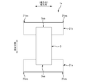
- FIG. 1A is a schematic enlarged view of a lateral end 11es of a pant-type diaper 1 '.
- each end in the lateral direction of the abdominal side part 11a and the back side part 11b is accompanied by the welding of the abdominal side part 11a and the back side part 11b.
- a plurality of welded portions j ′, j ′... Are formed in the portion 11es.
- the shape of each welded portion j ′ is a horizontally long rectangular shape that is long in the lateral direction, and each welded portion j ′ extends from the waistline opening 1HB to the leghole opening 1HL. They are arranged in a line.
- the tearing force is mainly concentrated on the boundary between the welded portion j ′ and the surrounding portion. Easy to act. That is, it tends to concentrate on the peripheral edge of the welded portion j '. Therefore, tentatively, the shape of the portion ju ′ on the waist opening 1HB side in the welded portion j ′ is displaced downward toward the longitudinal leg opening 1HL as it goes outward in the lateral direction as shown in FIG. 1B.
- the lateral outward force F applied by the operator's hand to the starting point that is the waistline opening 1HB can be quickly and naturally directed in the direction to be torn, It is considered that the film exhibits good tearability. Further, as described above, since a large force F is required at the beginning of tearing, the shape of the welded portions j ′, j ′... In the vicinity range A1HB of the waistline opening 1HB ′ at least among the end portions 11es is described above. It is considered effective if it is made into an inclined shape.
- the present invention has been made in view of the above-described conventional problems, and its purpose is to easily tear the end portion where the abdominal side portion and the back side portion are welded from the waistline opening. Although it is possible, it is to prevent the end portion from being inadvertently torn when worn.
- the main invention for achieving the above object is: An absorbent article having an abdominal side portion arranged on the abdomen side of the wearer at the time of wearing, a back side portion arranged on the back side of the wearer, and a crotch portion arranged between the crotch of the wearer.
- An absorbent article having an abdominal side portion arranged on the abdomen side of the wearer at the time of wearing, a back side portion arranged on the back side of the wearer, and a crotch portion arranged between the crotch of the wearer.
- a pants-type absorbent article in which a waistline opening and a pair of leghole openings are formed at positions different from each other in the longitudinal direction intersecting the lateral direction, A plurality of welds are formed at the end based on at least a weld pattern discontinuous in the longitudinal direction,
- the end portion has an inner region located on the inner side in the lateral direction, and an outer region located on the outer side in the lateral direction than the inner region,
- the predetermined range in the vertical direction starting from the waistline opening among the ends the size in the vertical direction of the gap between the welded portions adjacent in the vertical direction in the inner region
- the welded portion In the outer region, the welded portion is formed so as to be larger than the vertical size of the gap between the welded portions adjacent in the vertical direction,
- a welded portion having an inclined portion on the waistline opening side that is displaced toward the leghole opening in the vertical direction as it goes outward in the lateral direction,
- the end where the abdomen and the back are welded can be easily torn starting from the waistline opening, but the end is inadvertently torn at the time of wearing. Can also be prevented.
- FIG. 1A is a schematic enlarged view of a lateral end portion 11es of a conventional diaper 1 '
- FIG. 1B is a schematic enlarged view of an end portion 11es having good tearability.
- 3A is a schematic plan view of the unfolded diaper 1 as viewed from the skin side
- FIG. 3B is a schematic view taken along the line BB in FIG. 3A.
- An absorbent article having an abdominal side portion arranged on the abdomen side of the wearer at the time of wearing, a back side portion arranged on the back side of the wearer, and a crotch portion arranged between the crotch of the wearer.
- the abdomen and the dorsal part are overlapped by folding in two at the crotch part, the abdomen and the dorsal part are welded at respective lateral outer ends.
- a pants-type absorbent article in which a waistline opening and a pair of leghole openings are formed at positions different from each other in the longitudinal direction intersecting the lateral direction, A plurality of welds are formed at the end based on at least a weld pattern discontinuous in the longitudinal direction,
- the end portion has an inner region located on the inner side in the lateral direction, and an outer region located on the outer side in the lateral direction than the inner region,
- the predetermined range in the vertical direction starting from the waistline opening among the ends the size in the vertical direction of the gap between the welded portions adjacent in the vertical direction in the inner region
- the welded portion In the outer region, the welded portion is formed so as to be larger than the vertical size of the gap between the welded portions adjacent in the vertical direction,
- a welded portion having an inclined portion on the waistline opening side that is displaced toward the leghole opening in the vertical direction as it goes outward in the lateral direction,
- the end when removing the absorbent article from the wearer, the end can be easily torn from the waistline opening, but the end is inadvertently worn when worn. It can also be prevented from being torn. Details are as follows.
- the welded portion located in the inner region in the range near the waistline opening that is the predetermined range has an inclined portion that is displaced toward the longitudinal leghole opening as it proceeds outward in the lateral direction. Have on the side. Therefore, based on such an inclined shape, the lateral outward force applied to the waistline opening can be promptly guided in the direction torn as described above, thereby making it easy to It can be torn laterally from the inside to the outside.
- the vertical size of the gap between the welded portions adjacent in the vertical direction in the inner region is longer in the outer region. It is larger than the size in the vertical direction of the gap between the welds adjacent in the direction.
- the strength of the end portion is reduced based on the fact that the gap in the outer region is small. It can compensate effectively and can prevent that end part from being carelessly torn at the time of wearing.
- the outer region has a middle region adjacent to the inner region;
- the middle region is provided with a second welded portion and a third welded portion,
- the second welded portion has an inclined portion on the side of the leg opening that is displaced toward the leg opening in the vertical direction as it proceeds outward in the lateral direction
- the third welded portion has an inclined portion on the waistline opening side that is displaced toward the waistline opening in the vertical direction as it proceeds outward in the lateral direction
- a taper-shaped region that narrows in the vertical direction as the outer side in the lateral direction is divided in the middle region. Is desirable.
- the second welded portion and the third welded portion provided in the middle region cooperate with each other, and in the middle region, proceed in the vertical direction as proceeding outward in the lateral direction.
- the region of the tapered shape that is narrowed is divided. Since the tapered region is a non-welded part that is not welded, its strength is lower than that of the welded part. Therefore, the direction to be torn is guided to pass through this tapered region. As a result, the tearing direction is changed to a route substantially parallel to the lateral direction. And thereby, the said edge part can be torn by the shortest route nearest to the outer edge part of the horizontal direction in the edge part, and can make the said edge part easier to tear.
- the 2nd welding part and the 3rd welding part currently formed in the middle area are the magnitude
- the second welded portion has an inclined portion on the waistline opening side that is displaced toward the leghole opening in the vertical direction as it proceeds outward in the lateral direction, It is desirable that the inclined portion is provided along the inclined portion that the first welded portion has on the waistline opening side.
- the second welded portion in the middle region has the inclined portion on the waistline opening side, and the inclined portion is the first in the inner region.
- the welded portion is provided along an inclined portion of the waistline opening side. Therefore, in the middle region, the second welding portion can quickly take over the above-described force induction in the inner region based on the first welding portion. Therefore, also in the middle region, the above guidance can be continued quickly, and as a result, the end portion is more easily torn.
- the inclined portion that the second welded portion has on the waistline opening side has the same shape as the inclined portion that the first welded portion has on the waistline opening side, and the second welded portion. It is desirable that the first welded portion and the first welded portion are provided side by side in the lateral direction while being inclined from the lateral direction so that the portions having the inclined shapes are aligned on a straight line.
- the second welded portion can take over more quickly in the middle region while the induction of the force in the tearing direction made based on the first welded portion in the inner region. . Therefore, also in the middle region, it is possible to continue the above guidance more quickly, and as a result, the end portion is more easily torn.
- Such a pants-type absorbent article has an end region at a position outside in the lateral direction from the middle region, The end region is provided with a fourth welded portion, The fourth welded portion has an inclined portion on the waistline opening side that is displaced toward the waistline opening in the vertical direction as it proceeds outward in the lateral direction, The fourth welded portion is preferably provided so as to intersect with an extension line of the inclined portion of the second welded portion on the waistline opening side.
- the fourth welded portion in the end region is provided so as to intersect with the extended line of the inclined portion of the second welded portion in the middle region. Therefore, the tearing force along the tearing direction generated in the inner region and the middle region when the end portion is torn can be blocked by the end region, and this can be mitigated. As a result, the operator can tear the end portion in the lateral direction with a moderate force as a whole.
- Such a pants-type absorbent article It is desirable that the inclination of the inclined portion of the fourth welded portion is gentler than the inclination of the inclined portion of the second welded portion on the waistline opening side.
- the sloped portion of the fourth welded portion provided in the end region is more gradual than the sloped portion of the second welded portion provided in the middle region. It is formed with an inclination. Therefore, the fourth welded portion can gently block the tearing force along the tearing direction.
- the inclined portion of the fourth welded portion on the waistline opening side is preferably provided along the inclined shape portion of the third welded portion on the waistline opening side.
- the inclined portion that the fourth welded portion in the end region has on the waistline opening side is the inclined shape that the third welded portion in the middle region has on the waistline opening side. It is provided along the part. Therefore, the guide to the shortest route in the tearing direction made based on the third welded portion in the middle region can be quickly taken over by the fourth welded portion in the end region. Therefore, also in the said edge area
- the inclined part that the fourth welded part has on the waistline opening part side has the same shape as the inclined part that the third welded part has on the waistline opening part side, and the fourth welded part It is desirable that the third welded portion and the third welded portion are provided side by side in the horizontal direction while being inclined from the horizontal direction so that the portions of the inclined shape are aligned with each other.
- the fourth welded portion can take over more quickly in the end region while guiding to the shortest route in the middle region based on the third welded portion. . Therefore, also in the said edge area
- Such a pants-type absorbent article When the welded portion formed in the inner region and having the inclined portion is the first welded portion, In the inner region, it is preferable that a plurality of the first welded portions are formed side by side in the vertical direction over the entire length in the vertical direction from the waistline opening to the leg opening.
- the force applied from the operator's hand is quickly and naturally guided in the aforementioned tearing direction over the entire length of the inner region in the vertical direction. That is, the force is guided in a direction displaced toward the leg opening in the vertical direction as it goes outward in the horizontal direction. Therefore, the end portion can be torn quickly and easily.
- Such a pants-type absorbent article Each of the ventral portion and the dorsal side portion is fixed along the lateral direction with an elastic member extending in the lateral direction, It is desirable that some of the welded portions are formed in a portion where the elastic member is not located at the end portion.
- the strength of the several welded parts is reduced. For this reason, the end portion is easily torn by the decrease in strength.
- the reason why the strength of the several welded portions is lowered, that is, the reason why the strength of the welded portion formed in the portion where the elastic member is not located is as follows. First, the welded portion is usually formed using a pair of sandwiching members.
- one sandwiching member has a plurality of projections corresponding to the welding pattern
- the other sandwiching member has a plane that receives the projections
- the portion where the elastic member is not located is thinner in the sandwiching direction by the amount corresponding to the elastic member than the portion where the elastic member is located. Therefore, at the time of sandwiching by the pair of sandwiching members, the sandwiching force applied by the thin thickness is reduced and welding is difficult to proceed, and as a result, the welding portion formed in the portion where the elastic member is not located. The strength is lowered.
- Each of the ventral portion and the dorsal side portion is fixed by a hot melt adhesive along the lateral direction with an elastic member extending in the lateral direction, It is desirable that some of the welded portions are formed by performing an ultrasonic welding process on a portion of the end portion where the elastic member is located.
- the strength of the several welded parts is reduced. For this reason, the end portion is easily torn by the decrease in strength.
- the reason why the strength of the several welded parts is lowered is as follows. First, an elastic member is fixed with a hot melt adhesive at a portion where the several welds are formed at the end, and an ultrasonic welding process is performed on the portion where the hot melt adhesive exists. And the frictional heat generation of the ultrasonic welding process is suppressed based on the lubricating action by the adhesive. Therefore, the welding process is difficult to proceed, and as a result, the strength of the welded portion is lowered.
- FIG. 2 is a schematic perspective view of a pant-type disposable diaper 1 as an example of the pant-type absorbent article of the present embodiment.
- 3A is a schematic plan view of the unfolded diaper 1 as viewed from the skin side
- FIG. 3B is a schematic view taken along the line BB in FIG. 3A.
- FIG. 4 is an exploded schematic perspective view showing the diaper 1 in the unfolded state.
- FIG. 5 is a schematic plan view of the unfolded exterior sheet 11 as seen from the non-skin side.
- the side that should be located on the skin side of the wearer is simply referred to as “skin side”, and on the other hand, on the non-skin side of the wearer.
- the side to be positioned is simply referred to as the “non-skin side”.
- this diaper 1 is a two-piece type diaper 1, for example. That is, the diaper 1 has, as a first part, an absorbent main body 3 having a substantially rectangular shape in plan view that absorbs excretory fluid such as urine, and is provided to cover the non-skin side surface of the absorbent main body 3.
- the exterior sheet 11 having a substantially hourglass shape in plan view that forms the exterior of the diaper 1 is provided as the second component.
- the absorbent main body 3 has an absorbent core 3c that absorbs excretory fluid.
- the absorbent core 3c is formed by molding liquid absorbent fibers such as pulp fibers and liquid absorbent granular materials such as superabsorbent polymers into a substantially hourglass shape in plan view as an example of a predetermined shape.
- this absorptive core 3c may be coat
- the skin side surface of the absorbent core 3c is provided with a liquid-permeable top sheet 4 such as a nonwoven fabric so as to cover the entire surface, and similarly, on the non-skin side surface of the absorbent core 3c.
- a liquid-impermeable leak-proof sheet 5 such as a film so as to cover the entire surface.
- both the sheets 4 and 5 are formed in a substantially rectangular shape in plan view, and both the sheets 4 and 5 are outside the outer contour of the absorbent core 3c over the entire circumference. Is jumping out.
- the part which protruded in the top sheet 4 and the part which protruded in the leak-proof sheet 5 are mutually joined by adhesion
- the absorptive main body 3 of planar view substantially rectangular shape is formed. .
- thread rubber as an elastic member may be provided along the longitudinal direction of the main body 3 at both ends of the absorbent main body 3 in the width direction.
- Such a rubber thread imparts elasticity to the vicinity of the leg opening 1HL in the absorbent main body 3 and the exterior sheet 11. Therefore, the rubber thread is inserted between the top sheet 4 and the leak-proof sheet 5 and is stretched from a natural length to a predetermined magnification such as 2 to 4 times by an adhesive such as a hot melt adhesive. It is fixed to both sheets 4 and 5.
- a leak-proof wall may be provided in the absorbent main body 3 for the purpose of preventing side leakage of urine.
- a leak-proof wall portion is also called a three-dimensional gather, and is provided so as to stand at both end portions such as the skin side surface of the absorbent main body 3 using a flexible sheet such as a nonwoven fabric as a material.
- this leak-proof wall part is a well-known structure. Therefore, further explanation is omitted.
- the exterior sheet 11 is a flexible sheet having a substantially hourglass shape in plan view in the unfolded state of FIG. 5, and the sheet 11 has a thickness direction, a longitudinal direction, and a width direction as three directions orthogonal to each other. ing. Moreover, the said exterior sheet
- seat 11 is divided into three parts 11a, 11b, and 11c regarding a longitudinal direction. That is, the exterior sheet 11 is provided on the abdomen side portion 11a disposed on the wearer's belly side, the back side portion 11b disposed on the wearer's back side, and the crotch portion 11c disposed on the wearer's crotch. It is divided.
- the crotch part 11c is located between the abdominal part 11a and the dorsal part 11b, so that the crotch part 11c has a shape that is constricted in the width direction in a substantially hourglass shape in plan view. This is a portion 11c.
- the exterior sheet 11 has a single sheet 12 as a main body, or a laminated sheet obtained by laminating and integrating a plurality of sheets as a main body.
- the main body the material of the sheet
- the SMS nonwoven fabric (spun bond) of 15 (g / m ⁇ 2 >) is used.
- / Melt blown / spunbond nonwoven fabric is used, but not limited to this.
- seat 13a, 13b is respectively provided in the non-skin side of the said sheet
- Another sheet is not joined to the crotch part 12c.
- the present invention is not limited to this, and another sheet may be joined to the crotch part 12c, and further, another sheet of the crotch part 12c is connected to another sheet 13a and a dorsal part 12b of the ventral part 12a.
- the other sheet 13b may be integrated.
- a nonwoven fabric including a thermoplastic resin fiber, a thermoplastic resin film, or the like is used as the material of the other sheets 13a and 13b.
- a basis weight of 17 (g / m 2 ) including a thermoplastic resin fiber is used as the material of the other sheets 13a and 13b.
- An amount of spunbond nonwoven is used, but not limited to this.
- the sheet 12 serving as the main body of the exterior sheet 11 is referred to as a “main body sheet 12”
- the other sheet 13 a bonded to the ventral side portion 12 a of the main body sheet 12 is referred to as a “belly side portion.
- the outer sheet 13a ” is referred to as the other sheet 13b joined to the back side portion 12b of the main body sheet 12 and is referred to as a“ back side outer sheet 13b ”.
- Thread rubbers 15, 15... are inserted.
- the thread rubbers 15, 15... Impart stretchability in the width direction to the abdomen side portion 11a and the back side portion 11b of the exterior sheet 11. Therefore, the rubber threads 15, 15... Are arranged along the width direction in a state of being stretched from the natural length to a predetermined magnification such as 2 to 4 times, and are spread out by the hot melt adhesive. , 13b.
- a plurality of the thread rubbers 15, 15... are arranged side by side in the longitudinal direction of the main body sheet 12 with a space between each other, whereby the longitudinal side portion 11a and the back side portion 11b have the longitudinal length. Stretchability is given over a wide range of directions.
- the abdomen outer sheet 13a and the dorsal outer sheet 13b are provided so as to protrude outward from the longitudinal edges 12eLa and 12eLb of the main body sheet 12, respectively.
- the portions 13ap and 13bp that protrude outward from the main body sheet 12 in the respective sheets 13a and 13b are folded back inward in the longitudinal direction.
- FIG. 13 ap and 13 bp are superimposed on the skin side surface of the main body sheet 12.
- the end edges 11HBa and 11HBb serving as the waistline opening 1HB are formed by the folded portion 13ak of the abdomen-side outer sheet 13a and the folded portion 13bk of the back-side outer sheet 13b.
- the edge portions 12eLa and 12eLb of the main body sheet 12 are covered with the portions 13ak and 13bk. Therefore, the skin of the wearer is prevented from being damaged by the edge portions 12eLa and 12eLb of the main body sheet 12.
- the protruding portions 13 ap and 13 bp superimposed on the skin side surface of the main body sheet 12 are further in the longitudinal direction of the absorbent main body 3.
- Each end 3ea, 3eb is also covered from the skin side, but is not limited to this. That is, it may not be covered.
- the above-described absorbent main body 3 is in a state in which the longitudinal directions thereof are aligned. It is fixed.
- the length in the longitudinal direction and the length in the width direction of the absorbent main body 3 are set such that the absorbent main body 3 can be generally accommodated inside the exterior sheet 11.
- the end portion 11es in the width direction welded as described above is also referred to as a “side end portion 11es”. Moreover, below, it defines as follows about the direction of the three-dimensional shape of the diaper 1 made into the underpants type like FIG. First, a direction parallel to the width direction of the exterior sheet 11 is referred to as a “lateral direction”. A direction parallel to the longitudinal direction of the exterior sheet 11 is referred to as a “longitudinal direction”. The horizontal direction and the vertical direction are orthogonal to each other as an example of the intersection. A direction perpendicular to both the horizontal direction and the vertical direction is referred to as a “front-rear direction”.
- the front in the front-rear direction is the abdomen side that is the front side of the wearer, and the rear side in the front-rear direction is the back side that is the rear side of the wearer.
- the vertical direction is the vertical direction, so the vertical direction is also referred to as the “vertical direction”.
- the leg opening 1HL is located below the waist opening 1HB.
- the central side in the horizontal direction is also referred to as “inside”, and the end side in the horizontal direction is also referred to as “outside”.
- the side end portion 11es is provided at a laterally outer position in the diaper 1, and the absorbent main body 3 is disposed at a laterally inner position in the diaper 1.
- the above-described welding is performed by an ultrasonic welding process, a heat seal process, or the like, and in this example, an ultrasonic welding process is performed.
- a plurality of welded portions j, j... Are respectively welded to the end portions 11es in the lateral direction of the belly side portion 11a of the exterior sheet 11 of FIG.
- a plurality of welded portions j, j (not shown in FIG. 2) are also based on the same welding pattern on each side end portion 11es of the back side portion 11b of the exterior sheet 11 as well. Is formed.
- each welding part j, j ... of these abdominal side parts 11a and each j, j ... of the back side part 11b are united, and it is what is called the same that has the positional relationship of the front and back in said side edge part 11es. Is. Therefore, no distinction is made in the following description.
- FIGS. 7A and 7B show the upper portion of the welding pattern in an enlarged manner.
- the welding pattern as a whole has a band shape that is long in the vertical direction.
- the welding pattern extends over almost the entire length of the side end portion 11es from the waist opening 1HB to the leg opening 1HL.
- the same pattern is a discontinuous pattern in both the vertical direction and the horizontal direction, so that a plurality of welded portions j, j... Are adjacent to the welded portions j, j adjacent in the vertical direction and the horizontal direction, respectively. It is arranged with a gap between them.
- each welded portion j is formed to be recessed in the front-rear direction (direction passing through the paper surface in FIG. 6), and in this example, the shape of the bottom surface of each welded portion j is a horizontally long parallelogram. I am doing.
- the side end portion 11es has three vertically long strip regions Ain, Amid, Aout arranged in the horizontal direction. That is, a vertically long strip-shaped inner region Ain positioned inside in the lateral direction, a vertically striped middle region Amid positioned laterally outside the inner region Ain, and a laterally outer side positioned relative to the middle region Amid. And an end region Aout having a vertically long strip shape.
- regions Amid and Aout formed by combining both the middle region Amid and the end region Aout correspond to “outer regions” according to the claims. That is, it corresponds to an “outer region located laterally outside the inner region”.
- first welded portion j1 the welded portion j provided in the inner region Ain is referred to as “first welded portion j1” for the purpose of distinguishing and explaining the welded portions j, j... Formed in the regions Ain, Amid, Aout.
- second welded portion j2 two types of welded portions j and j as examples of a plurality of types provided in the middle region Amid are referred to as “second welded portion j2” and “third welded portion j3”, respectively, and are provided in the end region Aout.
- the welded portion j to be obtained is referred to as “fourth welded portion j4”.
- each 1st welding part j1 of a parallelogram shape is each inclined and provided so that it may be displaced to the downward direction of a vertical direction as it progresses to the outer side of a horizontal direction, Thereby, by this, 1st welding part j1
- the upper side portion j1u (corresponding to the inclined portion) has an inclined shape that is displaced downward in the vertical direction as it goes outward in the horizontal direction. And this inclination shape is along the direction (refer FIG. 1A) to which the above-mentioned torn.
- the “direction to be torn” referred to here means that, as described above with reference to FIG. 1A, the operator applies a force F to the waistline opening 1HB located at the upper end portion 11esu of the side end portion 11es.
- the side end portion 11es refers to a direction in which the side end portion 11es is torn. As it goes on, it is directed in a direction displaced downward in the vertical direction, and correspondingly, the inclined shape is directed in the same direction.
- each first welded portion j1 can quickly guide the lateral outward force F applied to the waistline opening 1HB in the tearing direction based on the inclined shape, Thereby, the same side edge part 11es can be easily torn from the inner side of a horizontal direction to the outer side.
- the first welds j1 in the inner region Ain are provided side by side in the vertical direction so that wide gaps Ga and narrow gaps Gb appear alternately in the vertical direction.
- the vertical dimension of the wide gap Ga is the same value over all the wide gaps Ga, Ga...
- the vertical dimension of the narrow gap Gb is also all narrow. It is mutually equivalent over gap Gb, Gb ....
- the vertical arrangement pitch Pa of the pair of welded portions j1 and j1 provided across the wide gap Ga is the vertical direction of the pair of welded portions j1 and j1 provided across the narrow gap Gb.
- the arrangement pitch Pb is twice as large.
- the arrangement pitch may be another integer multiple such as triple, or the arrangement pitch may be a multiple of the magnification including a decimal point such as 1.5.
- a wide gap Ga is associated with the upper end portion of the inner region Ain.
- one upper welding portion j1 is provided at the upper end portion, and the first welding portion j1 is provided below the welding portion j1 with a wide gap Gb.
- the inclination angle value ⁇ 1 from the lateral direction of the upper side j1u and the lower side j1d of the first welded part j1 is selected from a range of 10 ° to 40 °, for example, and preferably from a range of 15 ° to 35 °. Selected, more preferably selected from the range of 20 ° to 25 °, in this example 22 °.
- the lateral dimension of the bottom surface of the first welded portion j1 is selected such that an arbitrary value of, for example, 1 mm to 4 mm is the maximum value, and the longitudinal dimension is also, for example, 0.5 mm to 1 An arbitrary value of 0.5 mm is selected to be the maximum value.
- the vertical dimension of the wide gap Ga is selected from 5 mm to 10 mm, for example, and the vertical dimension of the narrow gap Gb is selected from 1 mm to 4 mm, for example. However, it is not limited to these.
- the second welded portion j2 and the third welded portion j3 are provided in a row in the vertical direction as an example of a plurality of types. ing.
- the second welded portion j2 is a welded portion having substantially the same shape as the first welded portion j1 described above. That is, it has the same specifications as the first welded portion except that the lateral dimension is shorter by about 10 to 20% than the first welded portion j1. More specifically, the second welded portion j2 also has a parallelogram-shaped bottom surface, and the upper side portion j2u and the lower side portion j2d of the second welded portion j2 (both correspond to inclined portions).
- the inclination angle value ⁇ 2 from the horizontal direction of the upper side portion j2u and the lower side portion j2d is also the same as that of the first welded portion j1. It is the same value as the inclination angle value ⁇ 1.
- the second welded portion j2 is provided in correspondence with each first welded portion j1 of the inner region Ain. That is, the second welded portion j2 is arranged side by side on the lateral side of the first welded portion j1, and the upper side portion j2u of the second welded portion j2 is straight with the upper side portion j1u of the first welded portion j1. It is arranged in a state inclined from the horizontal direction so as to be aligned on the line.
- the second welded portion j2 can quickly take over the above-described force induction performed by the first welded portion j1 in the inner region Ain. In this case, the above-described guidance can be continued promptly. As a result, the side end portion 11es is more easily torn.
- the second welded portion j2 is basically also the first welded portion.
- the wide gap Ga and the narrow gap Gb are provided side by side in the vertical direction so that they appear alternately in the vertical direction.
- a second welded portion j2 is additionally provided at an intermediate position in the vertical direction of the wide gap Ga, so that the wide gap Ga is divided into two parts up and down. Two narrow gaps Gb and Gb adjacent to each other are formed. Therefore, in the middle region Amid, a plurality of second welded portions j2, j2,... Are arranged in the vertical direction with a short arrangement pitch Pb corresponding to the narrow gap Gb described above.
- the third welded portions j3 are also provided in the two narrow gaps Gb and Gb, respectively.
- the wide vertical gap Ga is subdivided.
- the size of the gap between the welded portions j, j adjacent to each other in the vertical direction is generally larger in the inner area Ain than in the middle area Amid.
- the wide gap Ga is correspondingly positioned at the upper end portion of the inner area Ain, and a portion corresponding to the wide gap Ga of the middle area Amid located on the side is one first.
- Two welded portions j2 and two third welded portions j3, j3 are provided, whereby the wide gap Ga is divided into four extremely narrow gaps.
- the vertical size of the gap between the welded portions j1 and j1 of the inner region Ain is made larger than the vertical size of the gap between the welded portions j2 and j3 of the middle region Amid. ing.
- the gap in the inner area Ain is large, it is possible to tear from the trunk opening 1HB of the upper end portion 11esu with good tearability, but the gap in the middle area Amid is small.
- the strength of the upper end portion 11esu can be effectively supplemented, and thereby, the side end portion 11es can be prevented from being inadvertently torn at the upper end portion 11esu when worn.
- the third welded portion j3 is also a welded portion having a parallelogram-shaped bottom surface.
- the inclination shape of the upper side portion j3u (corresponding to the inclined shape portion) of the third welded portion j3 is an inclined shape opposite to that of the first welded portion j1. That is, the upper side portion j3u of the third welded portion j3 is formed in an inclined shape that is displaced upward in the vertical direction as it goes outward in the horizontal direction, and the inclination angle value ⁇ 3 of the upper side portion j3u from the horizontal direction is also set.
- the inclination angle value ⁇ 1 of the first welded portion j1 is different from that described above. In this example, the inclination angle value ⁇ 3 of the third welded portion j3 is smaller.
- the second welded portion j2 is located next to the third welded portion j3 in the vertical direction.
- the bottom surface of the second welded portion j2 is located.
- the lower side j2d thereof is parallel to the upper side j2u. Therefore, the lower side j2d is also formed in an inclined shape that is displaced downward in the vertical direction as it goes outward in the horizontal direction.
- the second welded portion j2 and the third welded portion j3 cooperate with each other, so that a tapered region A23 that is narrowed in the vertical direction as it goes outward in the lateral direction is partitioned. Yes. And since this area
- each inclination angle value ⁇ 3 from the lateral direction of the upper side j3u and the lower side j3d of the third welded part j3 is selected from a range of 5 ° to 30 °, for example, and preferably from a range of 5 ° to 15 °. More preferably selected from the range of 7 ° to 12 °, in this example 10 °.
- the lateral dimension of the bottom surface of the third welded portion j3 is selected such that an arbitrary value of, for example, 1 mm to 4 mm is the maximum value.
- the longitudinal dimension is 0.5 mm to 1 for example. An arbitrary value of 0.5 mm is selected to be the maximum value.
- a plurality of fourth welded portions j4, j4,... are arranged in the longitudinal direction in the end region Aout adjacent to the outside of the middle region Amid.
- the 4th welding part j4 is a welding part of the substantially same shape as the above-mentioned 3rd welding part j3. That is, it has the same specifications as the third welded portion j3 except that the lateral dimension is longer by about 10 to 20% than the third welded portion j3.
- the fourth welded portion j4 also has a parallelogram-shaped bottom surface, and the upper side j4u and the lower side j4d of the fourth welded portion j4 are arranged in the vertical direction as they go outward in the horizontal direction.
- the inclination angle value ⁇ 4 from the lateral direction of the upper side portion j4u and the lower side portion j4d is the same value as the inclination angle value ⁇ 3 of the third welded portion j3.
- the fourth welded portion j4 is provided corresponding to at least each third welded portion j3 of the middle region Amid. That is, the fourth welded portion j4 is arranged side by side on the outer side in the lateral direction of the third welded portion j3, and the upper side portion j4u (corresponding to an inclined portion) of the fourth welded portion j4 is the third welded portion. It is arranged in a state inclined from the lateral direction so as to be aligned with the upper side part j3u of the part j3.
- the fourth welded portion j4 can quickly take over the guide to the shortest route in the tearing direction made based on the third welded portion j3 in the middle region Amid. Therefore, also in the end region Aout, the above guidance can be continued promptly, and as a result, the side end portion 11es can be more reliably torn by the shortest route.
- the fourth welded portion j4 intersects the extension line of the upper side portion j2u of the second welded portion j2 in the middle region Amid. Therefore, when tearing the side end portion 11es, the momentum of tearing along the tearing direction generated in the inner region Ain and the middle region Amid can be interrupted and alleviated. As a result, the operator can tear the side end portion 11es laterally with a moderate momentum.
- the fourth welded portion j4 is provided so as to correspond to all the second welded portions j2, j2... Provided in the middle region Amid. Therefore, the above-described momentum mitigating action can be reliably achieved.
- the inclination angle value ⁇ 4 from the lateral direction of the upper side portion j4u of the fourth welded portion j4 is smaller than the inclination angle value ⁇ 2 in the lateral direction of the upper side portion j2u of the second welded portion j2. Therefore, the fourth welded portion j4 can gently block the tearing force along the tearing direction.
- the welding pattern has the four types of welded portions j, ie, the first to fourth welded portions j1, j2, j3, and j4.
- the present invention is not limited to this. That is, another type of welded portion j may be added, or any one or two of the second to fourth welded portions j2, j3, and j4 may be omitted. .
- the following may be performed.
- the example of FIG. 8A is a case where the first welded portion j1, the second welded portion j2, and the third welded portion j3 are included, and the fourth welded portion j4 is not included.
- FIG. 8B is a case where it has the 1st welding part j1 and the 2nd welding part j2, and does not have the 3rd welding part j3 and the 4th welding part j4.
- the example of FIG. 8C is a case where it has the 1st welding part j1, the 2nd welding part j2, and the 4th welding part j4, and does not have the 3rd welding part j3.
- the first welded part j1 and the second welded part j2 nearest to the first welded part j1 may be connected to form one welded part j12.
- the third welded part j3 and the nearest fourth welded part j4 may be connected to form one welded part j34.
- the strength of the welded portions j12 and j34 increases, and the tearability deteriorates. Therefore, it is better not to connect.
- gum 15,15 ... is hot in a horizontal direction in the state which extended to the abdominal side part 11a and the back
- some of the welded portions ja, ja... Of the welded portions j, j... Are portions where the thread rubber 15 is located at the side end portion 11es. It is formed by being subjected to ultrasonic welding treatment. And if it does in this way, the intensity
- the thread rubber 15 is fixed with a hot melt adhesive at a portion where the several welds ja are formed at the side end portion 11es, and ultrasonic welding is performed at a portion where the hot melt adhesive is present.
- the frictional heat generation of the ultrasonic welding process is suppressed based on the lubricating action of the adhesive. Therefore, the welding process is difficult to proceed, and as a result, the strength of the welded portion ja is lowered.
- the thread rubbers 15, 15... are fixed to the abdomen side part 11a and the back side part 11b by welding, the thread rubber 15 is positioned at the side end part 11es as shown in FIG.
- the strength of the welded portion jb formed in the portion not to be bonded is lower than the strength of the welded portion ja formed in the portion where the thread rubber 15 is located. Therefore, in this case, from the viewpoint of tearability, it is preferable to form the welded portion jb in a portion where the thread rubber 15 is not located in the side end portion 11es.
- the reason why the strength of the welded portion jb formed in the portion where the thread rubber 15 is not located is lowered is as follows. First, the welds j, j...
- one sandwiching member has a plurality of protrusions corresponding to the welding pattern
- the other sandwiching member has a plane that receives the protrusions
- the protrusions of one sandwiching member and the other sandwiching member The side end portions 11es are sandwiched between these sandwiching members from both sides in the front-rear direction while being arranged so as to face each other, thereby forming a plurality of welded portions j, j.
- the portion where the thread rubber 15 is not located has a smaller thickness in the front-rear direction corresponding to the thread rubber 15 as compared with the portion where the thread rubber 15 is located. Yes.
- FIG. 11 is an explanatory diagram of a modified example of the welding pattern.
- the welded portions j, j... are formed in the same pattern over the entire length in the vertical direction of the side end portion 11es, but the present invention is not limited to this.
- the side end portion 11es is divided into two upper and lower regions Au and Ad with respect to the vertical direction, and the upper region Au and the lower region Ad are based on different welding patterns.
- Welded portions j, j... Are formed.
- the upper region Au is referred to as “upper region Au”
- the lower region Ad is referred to as “lower region Ad”.
- the upper region Au has a length that is approximately two-thirds of the total length of the side end portion 11es downward from the upper end portion 11esu of the side end portion 11es, while the lower region Ad has a length that is approximately one third of the entire length of the side end portion 11es upward from the lower end portion 11esd of the side end portion 11es.
- the welding pattern of the upper region Au is the same as the above-described welding pattern (FIG. 6), but the welding pattern of the lower region Ad is different from the above-described welding pattern (FIG. 6). Therefore, hereinafter, only the welding pattern of the lower region Ad will be described, and description of the welding pattern of the upper region Au will be omitted.
- the lower region Ad also has an inner region Ain, a middle region Amid, and an end region Aout side by side in the horizontal direction.
- a plurality of fifth welded portions j5, j5... Similar to the first welded portion j1 are formed at a predetermined arrangement pitch in the vertical direction, and in the middle region Amid, the second welded portion j2 is formed.
- a plurality of similar sixth welded portions j6, j6... And a plurality of seventh welded portions j7, j7... Similar to the third welded portion j3 are alternately formed at a predetermined arrangement pitch in the vertical direction, and
- the fifth to eighth welded portions j5, j6. , J7, and j8 each have a parallelogram-shaped bottom surface, similar to the first to fourth welds j1, j2, j3, and j4 described above.
- the fifth welded portion j5 of the inner region Ain is inclined so as to be displaced downward in the vertical direction as it proceeds outward in the horizontal direction. Therefore, there exists an effect similar to the 1st welding part j1 of upper area
- the lower region Ad is adjacent in the vertical direction from the viewpoint of giving priority to prevention of tearing of the side end portion 11es starting from the leg opening 1HL at the time of wearing, with some sacrifice of tearability.
- the vertical size of the gap between the fifth welds j5, j5 is made smaller than the vertical size of the gap between the first welds j1, j1 adjacent in the vertical direction in the upper region Au. ing.
- the sixth weld j6 in the middle region Amid is inclined so as to be displaced downward in the vertical direction as it goes outward in the lateral direction, and thus the same effect as the second weld j2 in the upper region Au. Play. Further, the seventh welded portion j7 in the middle region Amid is inclined so as to be displaced upward in the vertical direction as it goes outward in the lateral direction, and thus the same effect as the third welded portion j3 in the upper region Au. Play.
- the vertical size of the gap between the sixth welded portion j6 and the seventh welded portion j7 adjacent in the vertical direction in the lower region Ad is vertical in the upper region Au. It is made smaller than the magnitude
- the eighth weld j8 in the end region Aout is inclined so as to be displaced upward in the vertical direction as it proceeds outward in the horizontal direction. Therefore, there exists an effect similar to the 4th welding part j4 of upper field Au.
- the vertical size of the gap between the eighth welds j8 and j8 adjacent in the vertical direction in the lower region Ad is fourth in the vertical direction in the upper region Au. It is made smaller than the magnitude
- the horizontally long parallelogram is shown as an example of the shape of each bottom surface of the first to eighth welds j1, j2,..., J8, but the present invention is not limited to this.
- a horizontally long rectangular shape, a horizontally long oval shape, or other shapes may be used.
- the welded portion j (j1, j2,..., J8) having a parallelogram-shaped bottom surface is illustrated
- the inclined shape of the welded portion opening 1HB side or leg opening 1HL side is provided.
- the upper side or the lower side in the parallelogram is illustrated. That is, although the inclined portion inclined linearly is illustrated, the present invention is not limited to this.
- the welded portion may have an inclined portion that is inclined in a curved line instead of the inclined portion that is inclined linearly.
- FIG. 3A a two-piece type diaper in which the absorbent main body 3 as the first part is covered with the exterior sheet 11 having a substantially hourglass shape in plan view as the second part from the non-skin side.
- 1 is illustrated, it is not limited to this.
- the diaper 1a has an absorptive main body 3 arranged between the wearer's crotch as a first part, and a ventral side band arranged on the abdomen side of the wearer as a second part. It has the member 21a, and has the back side belt member 21b arranged on the back side of the wearer as the third part. Further, in the deployed state of FIG. 12, the abdominal band member 21a and the back band member 21b are arranged in parallel with a space between each other, while the absorbent main body 3 is stretched between them, End portions 3ea and 3eb in the longitudinal direction of the absorbent main body 3 are bonded and fixed to the nearest belt members 21a and 21b, respectively, and the external shape thereof is substantially H-shaped in plan view.
- the absorbent main body 3 is folded in half at a substantially central portion in the longitudinal direction, and the band members 21a and 21b that are overlapped with each other in the folded state are widths orthogonal to the longitudinal direction.
- the band members 21a and 21b are connected to each other in an annular shape, thereby forming a waist opening and a pair of leg openings. It becomes diaper 1a.
- the above-mentioned welding part j (j1, j2, ..., j8) is applicable also to this welding.
- Each band member 21a, 21b is formed of a flexible sheet such as a nonwoven fabric including thermoplastic resin fibers.
- the structure of the absorptive main body 3 is substantially the same as the above-mentioned thing, it abbreviate
Landscapes
- Health & Medical Sciences (AREA)
- Epidemiology (AREA)
- Engineering & Computer Science (AREA)
- Biomedical Technology (AREA)
- Heart & Thoracic Surgery (AREA)
- Vascular Medicine (AREA)
- Life Sciences & Earth Sciences (AREA)
- Animal Behavior & Ethology (AREA)
- General Health & Medical Sciences (AREA)
- Public Health (AREA)
- Veterinary Medicine (AREA)
- Absorbent Articles And Supports Therefor (AREA)
Abstract
Description
装着時に着用者の腹側に配される腹側部と、前記着用者の背側に配される背側部と、前記着用者の股間に配される股下部とを有した吸収性物品を、前記股下部にて二つ折りして前記腹側部と前記背側部とを重ね合わせた状態で、前記腹側部と前記背側部とを横方向の外側の各端部でそれぞれ溶着することにより、前記横方向と交差する縦方向において互いに異なる位置に、胴回り開口部と一対の脚回り開口部とが形成されたパンツ型の吸収性物品であって、
前記端部には、少なくとも前記縦方向に非連続な溶着パターンに基づいて複数の溶着部が形成されており、
前記端部が、前記横方向の内側に位置する内側領域と、前記内側領域よりも前記横方向の外側に位置する外側領域とを有し、
前記端部のうちで前記胴回り開口部を起端とする前記縦方向の所定範囲には、前記内側領域において前記縦方向に隣り合う溶着部同士の間の隙間の前記縦方向の大きさが、前記外側領域において前記縦方向に隣り合う溶着部同士の間の隙間の前記縦方向の大きさよりも大きくなるように、溶着部が形成されており、
前記所定範囲における前記内側領域には、前記横方向の外側に進むに従って前記縦方向の前記脚回り開口部の方に変位した傾斜形状の部分を前記胴回り開口部側に有した溶着部が、前記縦方向に複数並んで形成されていることを特徴とするパンツ型の吸収性物品である。
本発明の他の特徴については、本明細書及び添付図面の記載により明らかにする。
装着時に着用者の腹側に配される腹側部と、前記着用者の背側に配される背側部と、前記着用者の股間に配される股下部とを有した吸収性物品を、前記股下部にて二つ折りして前記腹側部と前記背側部とを重ね合わせた状態で、前記腹側部と前記背側部とを横方向の外側の各端部でそれぞれ溶着することにより、前記横方向と交差する縦方向において互いに異なる位置に、胴回り開口部と一対の脚回り開口部とが形成されたパンツ型の吸収性物品であって、
前記端部には、少なくとも前記縦方向に非連続な溶着パターンに基づいて複数の溶着部が形成されており、
前記端部が、前記横方向の内側に位置する内側領域と、前記内側領域よりも前記横方向の外側に位置する外側領域とを有し、
前記端部のうちで前記胴回り開口部を起端とする前記縦方向の所定範囲には、前記内側領域において前記縦方向に隣り合う溶着部同士の間の隙間の前記縦方向の大きさが、前記外側領域において前記縦方向に隣り合う溶着部同士の間の隙間の前記縦方向の大きさよりも大きくなるように、溶着部が形成されており、
前記所定範囲における前記内側領域には、前記横方向の外側に進むに従って前記縦方向の前記脚回り開口部の方に変位した傾斜形状の部分を前記胴回り開口部側に有した溶着部が、前記縦方向に複数並んで形成されていることを特徴とするパンツ型の吸収性物品である。
一方、上記所定範囲たる胴回り開口部の近傍範囲に形成された溶着部については、内側領域において縦方向に隣り合う溶着部同士の間の隙間の縦方向の大きさの方が、外側領域において縦方向に隣り合う溶着部同士の間の隙間の縦方向の大きさよりも大きくなっている。よって、内側領域の上記隙間が大ききことに基づいて、胴回り開口部から引き裂き始めの良好な引き裂き性を担保しながらも、外側領域の上記隙間が小さいことに基づいて、上記端部の強度を有効に補うことができて、これにより、着用時に同端部が不用意に引き裂かれてしまうことを防ぐことができる。
前記外側領域は、前記内側領域に隣接して中領域を有し、
前記傾斜形状の部分を有した溶着部を第1溶着部とした場合に、
前記中領域には、第2溶着部と第3溶着部とが設けられており、
前記第2溶着部は、前記横方向の外側に進むに従って前記縦方向の前記脚回り開口部の方に変位した傾斜形状の部分を前記脚回り開口部側に有し、
前記第3溶着部は、前記横方向の外側に進むに従って前記縦方向の前記胴回り開口部の方に変位した傾斜形状の部分を前記胴回り開口部側に有し、
前記第2溶着部と前記第3溶着部とが互いに共同することによって、前記中領域には、前記横方向の外側に進むに従って前記縦方向に狭くなった先細り形状の領域が区画されているのが望ましい。
また、中領域に形成されている第2溶着部及び第3溶着部は、縦方向に隣り合う溶着部同士の間の隙間の大きさを、内側領域において縦方向に隣り合う溶着部同士の間の隙間の大きさよりも小さくすることにも、有効に寄与する。
前記第2溶着部は、前記横方向の外側に進むに従って前記縦方向の前記脚回り開口部の方に変位した傾斜形状の部分を前記胴回り開口部側に有し、
前記傾斜形状の部分は、前記第1溶着部が前記胴回り開口部側に有する前記傾斜形状の部分に沿って設けられているのが望ましい。
前記第2溶着部が前記胴回り開口部側に有する前記傾斜形状の部分は、前記第1溶着部が前記胴回り開口部側に有する前記傾斜形状の部分と同じ形状であるとともに、当該第2溶着部と前記第1溶着部とは、互いの前記傾斜形状の部分が一直線上に揃うように前記横方向から傾きつつ前記横方向に並んで設けられているのが望ましい。
前記外側領域は、前記中領域よりも前記横方向の外側の位置に端領域を有し、
前記端領域には、第4溶着部が設けられており、
前記第4溶着部は、前記横方向の外側に進むに従って前記縦方向の前記胴回り開口部の方に変位した傾斜形状の部分を前記胴回り開口部側に有し、
前記第4溶着部は、前記第2溶着部が前記胴回り開口部側に有する前記傾斜形状の部分の延長線と交差するように設けられているのが望ましい。
前記第4溶着部の前記傾斜形状の部分の傾斜の方が、前記第2溶着部が前記胴回り開口部側に有する前記傾斜形状の部分の傾斜よりも緩やかであるのが望ましい。
前記第4溶着部が前記胴回り開口部側に有する前記傾斜形状の部分は、前記第3溶着部が前記胴回り開口部側に有する前記傾斜形状の部分に沿って設けられているのが望ましい。
前記第4溶着部が前記胴回り開口部側に有する前記傾斜形状の部分は、前記第3溶着部が前記胴回り開口部側に有する前記傾斜形状の部分と同じ形状であるとともに、当該第4溶着部と前記第3溶着部とは、互いの前記傾斜形状の部分が一直線上に揃うように前記横方向から傾きつつ前記横方向に並んで設けられているのが望ましい。
前記内側領域に形成されて前記傾斜形状の部分を有する前記溶着部を第1溶着部とした場合に、
前記内側領域には、前記胴回り開口部から前記脚回り開口部までの前記縦方向の全長に亘って、前記第1溶着部が、前記縦方向に複数並んで形成されているのが望ましい。
かかるパンツ型の吸収性物品であって、
前記腹側部及び前記背側部には、それぞれ、弾性部材が前記横方向に伸長した状態で前記横方向に沿って固定されており、
前記溶着部のうちの幾つかの溶着部は、前記端部において前記弾性部材が位置しない部分に形成されているのが望ましい。
先ず、溶着部の形成は、通常一対の挟み込み部材を用いてなされる。すなわち、一方の挟み込み部材は、溶着パターンに対応した複数の突部を有し、他方の挟み込み部材は、同突部を受ける平面を有し、そして、一方の挟み込み部材の突部と他方の挟み込み部材の平面とが対向するように配置しながら、上記端部がこれら一対の挟み込み部材に挟み込まれることによって複数の溶着部が形成される。ここで、上記端部のうちで弾性部材が位置しない部分は、弾性部材が位置する部分と比べて、弾性部材の分だけ挟み込み方向の厚さが薄くなっている。そのため、上記一対の挟み込み部材による挟み込み時には、厚さが薄い分だけ付与される挟圧力が小さくなって溶着が進行し難くなり、その結果として、弾性部材が位置しない部分に形成された溶着部の強度は低くなる。
前記腹側部及び前記背側部には、それぞれ、弾性部材が前記横方向に伸長した状態で前記横方向に沿ってホットメルト接着剤によって固定されており、
前記溶着部のうちの幾つかの溶着部は、前記端部において前記弾性部材が位置する部分に超音波溶着処理が施されることにより形成されているのが望ましい。
なお、上記幾つかの溶着部の強度が低下する理由については、次の通りである。先ず、上記端部において上記幾つかの溶着部が形成される部分には、弾性部材がホットメルト接着剤で固定されているが、かかるホットメルト接着剤が存在する部分に超音波溶着処理を行うと、同接着剤による潤滑作用に基づいて超音波溶着処理の摩擦発熱が抑制されてしまう。よって、同溶着処理が進行し難くなって、結果、上記溶着部の強度が低くなる。
図2は、本実施形態のパンツ型の吸収性物品の一例としてのパンツ型の使い捨ておむつ1の概略斜視図である。図3Aは、展開状態のおむつ1を肌側から見た概略平面図であり、図3Bは、図3A中のB-B矢視の概略図である。図4は、展開状態のおむつ1を分解して示す概略斜視図である。図5は、展開状態の外装シート11を非肌側から見た概略平面図である。
また、以下では、同図2の如くパンツ型にされたおむつ1の三次元形状の方向について、次のように定義する。先ず、外装シート11の幅方向と平行な方向のことを「横方向」と言う。また、外装シート11の長手方向と平行な方向のことを「縦方向」と言う。横方向と縦方向とは、交差の一例として直交している。また、横方向と縦方向との両者と直交する方向のことを「前後方向」と言う。なお、前後方向の前方が、着用者の前側たる腹側であり、同前後方向の後方が、着用者の後側たる背側である。また、おむつ1を装着した際には、上記の縦方向は上下方向を向くことから、縦方向のことを「上下方向」とも言う。ちなみに、上下方向で言えば、脚回り開口部1HLは、胴回り開口部1HBよりも下方に位置している。更に、横方向の中央側のことを「内側」とも言い、横方向の端側のことを「外側」とも言う。例えば、上記の側端部11esは、おむつ1における横方向の外側の位置に設けられており、また、上記の吸収性本体3は、おむつ1における横方向の内側の位置に設けられている。
かかる内側領域Ainの各第1溶着部j1は、縦方向に広い隙間Gaと狭い隙間Gbとが交互に現れるように、縦方向に並んで設けられている。そして、この例では、広い隙間Gaの縦方向の寸法は、全ての広い隙間Ga,Ga…に亘って互いに同値とされており、同様に、狭い隙間Gbの縦方向の寸法も、全ての狭い隙間Gb,Gb…に亘って互いに同値とされている。また、この例では、広い隙間Gaを挟んで設けられた一対の溶着部j1,j1の縦方向の配置ピッチPaは、狭い隙間Gbを挟んで配された一対の溶着部j1,j1の縦方向の配置ピッチPbの二倍の大きさとされている。但し、何等これに限らない。例えば、三倍等の他の整数倍の大きさの配置ピッチにしても良いし、1.5倍などの小数点を含む倍率倍の大きさの配置ピッチにしても良い。
第2溶着部j2は、前述の第1溶着部j1と概ね同じ形状の溶着部である。すなわち、第1溶着部j1よりも1割から2割程度横方向の寸法が短くなっていること以外は、第1溶着部と同仕様である。より詳しくは、この第2溶着部j2も、平行四辺形形状の底面を有し、そして、この第2溶着部j2の上辺部j2u及び下辺部j2d(どちらも、傾斜形状の部分に相当)は、横方向の外側に進むに従って縦方向の下方に変位した傾斜形状に形成され、更に、この上辺部j2u及び下辺部j2dの横方向からの傾斜角度値θ2も、前述の第1溶着部j1の傾斜角度値θ1と同値である。
また、第4溶着部j4の上辺部j4uの横方向からの傾斜角度値θ4は、第2溶着部j2の上辺部j2uの横方向の傾斜角度値θ2よりも小さくなっている。よって、第4溶着部j4は、上記の引き裂かれる方向に沿った引き裂きの勢いを緩やかに遮ることができる。
先ず、側端部11esにおいて上記幾つかの溶着部jaが形成される部分には、糸ゴム15がホットメルト接着剤で固定されているが、かかるホットメルト接着剤が存在する部分に超音波溶着処理を行うと、同接着剤による潤滑作用に基づいて超音波溶着処理の摩擦発熱が抑制されてしまう。よって、溶着処理が進行し難くなって、結果、上記溶着部jaの強度が低くなる。
先ず、溶着部j,j…の形成は、不図示の一対の挟み込み部材を用いてなされる。すなわち、一方の挟み込み部材は、溶着パターンに対応した複数の突部を有し、他方の挟み込み部材は、突部を受ける平面を有し、そして、一方の挟み込み部材の突部と他方の挟み込み部材の平面とが対向するように配置しながら、側端部11esが縦方向の全長に亘ってこれら挟み込み部材に前後方向の両側から挟み込まれることによって複数の溶着部j,j…が形成される。ここで、上記側端部11esのうちで糸ゴム15が位置しない部分は、糸ゴム15が位置する部分と比べて、糸ゴム15の分だけ挟み込み方向たる上記前後方向の厚さが薄くなっている。そのため、上記一対の挟み込み部材による挟み込み時には、厚さが薄い分だけ付与される挟圧力が小さくなって溶着が進行し難くなり、その結果として、糸ゴム15が位置しない部分に形成された溶着部jbの強度は低くなる。
以上、本発明の実施形態について説明したが、上記の実施形態は、本発明の理解を容易にするためのものであり、本発明を限定して解釈するためのものではない。また、本発明は、その趣旨を逸脱することなく、変更や改良され得るとともに、本発明にはその等価物が含まれるのはいうまでもない。例えば、以下に示すような変形が可能である。
先ず、図12に示すように、同おむつ1aは、第1部品として着用者の股間に配される吸収性本体3を有し、第2部品として同着用者の腹側に配される腹側帯部材21aを有し、第3部品として同着用者の背側に配される背側帯部材21bを有している。また、図12の展開状態では、腹側帯部材21aと背側帯部材21bとが互いの間に間隔をあけて平行に並んだ状態で、これらの間に吸収性本体3が掛け渡されつつ、同吸収性本体3の長手方向の各端部3ea,3ebがそれぞれ最寄りの帯部材21a,21bに接合固定されており、その外観形状は平面視略H形状をなしている。そして、この展開状態から、吸収性本体3が長手方向の略中央部で二つ折りされるとともに、この二つ折りの状態において互いに重ね合わせられる帯部材21a,21b同士が、上記長手方向と直交する幅方向(横方向に相当)の各端部21esにて溶着されると、これら帯部材21a,21b同士が環状に繋がって、これにより、胴周り開口部及び一対の脚周り開口部が形成されたおむつ1aとなる。そして、かかる溶着に対しても、前述の溶着部j(j1,j2,…,j8)を適用可能である。なお、各帯部材21a,21bは、熱可塑性樹脂繊維を含む不織布等の柔軟なシートを材料として形成される。また、吸収性本体3の構成は、前述したものと概ね同じであるので、その説明については省略する。
1HB 胴回り開口部、1HL 脚回り開口部、
3 吸収性本体、3ea 端部、3eb 端部、
3c 吸収性コア、4 トップシート、5 防漏シート、
11 外装シート、
11HBa 胴回り開口部となる端縁部、11HBb 胴回り開口部となる端縁部、
11a 腹側部、11b 背側部、11c 股下部、
11es 側端部(端部)、11es1 縁部
11esu 上端部、11esd 下端部、
12 本体シート、12a 腹側部、12b 背側部、12c 股下部、
12eLa 端縁部、12eLb 端縁部、
13a 腹側部外面シート、13ak 折り返し部、13ap 飛び出した部分、
13b 背側部外面シート、13bk 折り返し部、13bp 飛び出した部分、
15 糸ゴム(弾性部材)、
21a 腹側帯部材、21b 背側帯部材、21es 端部、
Au 上側領域、Ad 下側領域、
Ga 広い隙間、Gb 狭い隙間、
j 溶着部、
j1 第1溶着部、j1u 上辺部(傾斜形状の部分)、j1d 下辺部、
j2 第2溶着部、j2u 上辺部(傾斜形状の部分)、
j2d 下辺部(傾斜形状の部分)、
j3 第3溶着部、j3u 上辺部(傾斜形状の部分)、j3d 下辺部、
j4 第4溶着部、j4u 上辺部(傾斜形状の部分)、j4d 下辺部、
j5 第5溶着部、j6 第6溶着部、j7 第7溶着部、j8 第8溶着部、
j12 溶着部、j34 溶着部、
ja 溶着部、jb 溶着部、
Ain 内側領域、Amid 中領域(外側領域)、Aout 端領域(外側領域)、
A23 先細り形状の領域、
Claims (11)
- 装着時に着用者の腹側に配される腹側部と、前記着用者の背側に配される背側部と、前記着用者の股間に配される股下部とを有した吸収性物品を、前記股下部にて二つ折りして前記腹側部と前記背側部とを重ね合わせた状態で、前記腹側部と前記背側部とを横方向の外側の各端部でそれぞれ溶着することにより、前記横方向と交差する縦方向において互いに異なる位置に、胴回り開口部と一対の脚回り開口部とが形成されたパンツ型の吸収性物品であって、
前記端部には、少なくとも前記縦方向に非連続な溶着パターンに基づいて複数の溶着部が形成されており、
前記端部が、前記横方向の内側に位置する内側領域と、前記内側領域よりも前記横方向の外側に位置する外側領域とを有し、
前記端部のうちで前記胴回り開口部を起端とする前記縦方向の所定範囲には、前記内側領域において前記縦方向に隣り合う溶着部同士の間の隙間の前記縦方向の大きさが、前記外側領域において前記縦方向に隣り合う溶着部同士の間の隙間の前記縦方向の大きさよりも大きくなるように、溶着部が形成されており、
前記所定範囲における前記内側領域には、前記横方向の外側に進むに従って前記縦方向の前記脚回り開口部の方に変位した傾斜形状の部分を前記胴回り開口部側に有した溶着部が、前記縦方向に複数並んで形成されていることを特徴とするパンツ型の吸収性物品。 - 請求項1に記載のパンツ型の吸収性物品であって、
前記外側領域は、前記内側領域に隣接して中領域を有し、
前記傾斜形状の部分を有した溶着部を第1溶着部とした場合に、
前記中領域には、第2溶着部と第3溶着部とが設けられており、
前記第2溶着部は、前記横方向の外側に進むに従って前記縦方向の前記脚回り開口部の方に変位した傾斜形状の部分を前記脚回り開口部側に有し、
前記第3溶着部は、前記横方向の外側に進むに従って前記縦方向の前記胴回り開口部の方に変位した傾斜形状の部分を前記胴回り開口部側に有し、
前記第2溶着部と前記第3溶着部とが互いに共同することによって、前記中領域には、前記横方向の外側に進むに従って前記縦方向に狭くなった先細り形状の領域が区画されていることを特徴とするパンツ型の吸収性物品。 - 請求項2に記載のパンツ型の吸収性物品であって、
前記第2溶着部は、前記横方向の外側に進むに従って前記縦方向の前記脚回り開口部の方に変位した傾斜形状の部分を前記胴回り開口部側に有し、
前記傾斜形状の部分は、前記第1溶着部が前記胴回り開口部側に有する前記傾斜形状の部分に沿って設けられていることを特徴とするパンツ型の吸収性物品。 - 請求項3に記載のパンツ型の吸収性物品であって、
前記第2溶着部が前記胴回り開口部側に有する前記傾斜形状の部分は、前記第1溶着部が前記胴回り開口部側に有する前記傾斜形状の部分と同じ形状であるとともに、当該第2溶着部と前記第1溶着部とは、互いの前記傾斜形状の部分が一直線上に揃うように前記横方向から傾きつつ前記横方向に並んで設けられていることを特徴とするパンツ型の吸収性物品。 - 請求項2乃至4の何れかに記載のパンツ型の吸収性物品であって、
前記外側領域は、前記中領域よりも前記横方向の外側の位置に端領域を有し、
前記端領域には、第4溶着部が設けられており、
前記第4溶着部は、前記横方向の外側に進むに従って前記縦方向の前記胴回り開口部の方に変位した傾斜形状の部分を前記胴回り開口部側に有し、
前記第4溶着部は、前記第2溶着部が前記胴回り開口部側に有する前記傾斜形状の部分の延長線と交差するように設けられていることを特徴とするパンツ型の吸収性物品。 - 請求項5に記載のパンツ型の吸収性物品であって、
前記第4溶着部の前記傾斜形状の部分の傾斜の方が、前記第2溶着部が前記胴回り開口部側に有する前記傾斜形状の部分の傾斜よりも緩やかであることを特徴とするパンツ型の吸収性物品。 - 請求項5又は6に記載のパンツ型の吸収性物品であって、
前記第4溶着部が前記胴回り開口部側に有する前記傾斜形状の部分は、前記第3溶着部が前記胴回り開口部側に有する前記傾斜形状の部分に沿って設けられていることを特徴とするパンツ型の吸収性物品。 - 請求項7に記載のパンツ型の吸収性物品であって、
前記第4溶着部が前記胴回り開口部側に有する前記傾斜形状の部分は、前記第3溶着部が前記胴回り開口部側に有する前記傾斜形状の部分と同じ形状であるとともに、当該第4溶着部と前記第3溶着部とは、互いの前記傾斜形状の部分が一直線上に揃うように前記横方向から傾きつつ前記横方向に並んで設けられていることを特徴とするパンツ型の吸収性物品。 - 請求項1乃至8の何れかに記載のパンツ型の吸収性物品であって、
前記内側領域に形成されて前記傾斜形状の部分を有する前記溶着部を第1溶着部とした場合に、
前記内側領域には、前記胴回り開口部から前記脚回り開口部までの前記縦方向の全長に亘って、前記第1溶着部が、前記縦方向に複数並んで形成されていることを特徴とするパンツ型の吸収性物品。 - 請求項1乃至9の何れかに記載のパンツ型の吸収性物品であって、
前記腹側部及び前記背側部には、それぞれ、弾性部材が前記横方向に伸長した状態で前記横方向に沿って固定されており、
前記溶着部のうちの幾つかの溶着部は、前記端部において前記弾性部材が位置しない部分に形成されていることを特徴とするパンツ型の吸収性物品。 - 請求項1乃至9の何れかに記載のパンツ型の吸収性物品であって、
前記腹側部及び前記背側部には、それぞれ、弾性部材が前記横方向に伸長した状態で前記横方向に沿ってホットメルト接着剤によって固定されており、
前記溶着部のうちの幾つかの溶着部は、前記端部において前記弾性部材が位置する部分に超音波溶着処理が施されることにより形成されていることを特徴とするパンツ型の吸収性物品。
Priority Applications (4)
| Application Number | Priority Date | Filing Date | Title |
|---|---|---|---|
| EP15786632.8A EP3138545A4 (en) | 2014-04-28 | 2015-01-20 | Underpants-type absorbent article |
| US15/307,004 US20170049639A1 (en) | 2014-04-28 | 2015-01-20 | Underpants-type absorbent article |
| CN201580023497.1A CN106456407B (zh) | 2014-04-28 | 2015-01-20 | 短裤型的吸收性物品 |
| AU2015254457A AU2015254457B2 (en) | 2014-04-28 | 2015-01-20 | Underpants-type absorbent article |
Applications Claiming Priority (2)
| Application Number | Priority Date | Filing Date | Title |
|---|---|---|---|
| JP2014092701A JP5895019B2 (ja) | 2014-04-28 | 2014-04-28 | パンツ型の吸収性物品 |
| JP2014-092701 | 2014-04-28 |
Publications (1)
| Publication Number | Publication Date |
|---|---|
| WO2015166671A1 true WO2015166671A1 (ja) | 2015-11-05 |
Family
ID=54358412
Family Applications (1)
| Application Number | Title | Priority Date | Filing Date |
|---|---|---|---|
| PCT/JP2015/051383 WO2015166671A1 (ja) | 2014-04-28 | 2015-01-20 | パンツ型の吸収性物品 |
Country Status (8)
| Country | Link |
|---|---|
| US (1) | US20170049639A1 (ja) |
| EP (1) | EP3138545A4 (ja) |
| JP (1) | JP5895019B2 (ja) |
| CN (1) | CN106456407B (ja) |
| AU (1) | AU2015254457B2 (ja) |
| MY (1) | MY159759A (ja) |
| TW (1) | TWI694814B (ja) |
| WO (1) | WO2015166671A1 (ja) |
Cited By (1)
| Publication number | Priority date | Publication date | Assignee | Title |
|---|---|---|---|---|
| WO2016189906A1 (ja) * | 2015-05-27 | 2016-12-01 | ユニ・チャーム株式会社 | 使い捨て着用物品 |
Families Citing this family (10)
| Publication number | Priority date | Publication date | Assignee | Title |
|---|---|---|---|---|
| RU2763484C2 (ru) * | 2017-05-31 | 2021-12-29 | Кимберли-Кларк Ворлдвайд, Инк. | Замкнутые по бокам впитывающие изделия, раскрывающиеся спереди или сзади |
| MX2019013006A (es) | 2017-05-31 | 2020-02-05 | Kimberly Clark Co | Articulos absorbentes con lados cerrados con abertura delantera o posterior. |
| JP6503432B1 (ja) * | 2017-10-04 | 2019-04-17 | ユニ・チャーム株式会社 | 伸縮性シート及び吸収性物品 |
| JP6503431B1 (ja) * | 2017-10-04 | 2019-04-17 | ユニ・チャーム株式会社 | 伸縮性シート及び吸収性物品 |
| JP6902997B2 (ja) * | 2017-12-27 | 2021-07-14 | ユニ・チャーム株式会社 | 吸収性物品の製造方法 |
| JP6363314B1 (ja) * | 2018-03-28 | 2018-07-25 | ユニ・チャーム株式会社 | 吸収性物品 |
| JP6906495B2 (ja) * | 2018-12-25 | 2021-07-21 | ユニ・チャーム株式会社 | パンツ型吸収性物品 |
| JP7041729B1 (ja) | 2020-10-02 | 2022-03-24 | 株式会社リブドゥコーポレーション | 使い捨て吸収性物品 |
| JP7045437B1 (ja) | 2020-10-27 | 2022-03-31 | 株式会社リブドゥコーポレーション | 使い捨て吸収性物品 |
| JP2023079873A (ja) * | 2021-11-29 | 2023-06-08 | 大王製紙株式会社 | パンツタイプ使い捨て着用物品 |
Citations (5)
| Publication number | Priority date | Publication date | Assignee | Title |
|---|---|---|---|---|
| JP2003093445A (ja) * | 2001-09-27 | 2003-04-02 | Oji Paper Co Ltd | パンツ型使い捨ておむつ |
| JP2003144494A (ja) * | 2001-11-09 | 2003-05-20 | Uni Charm Corp | パンツ型使い捨ておむつ及びその製造方法 |
| WO2008069281A1 (ja) * | 2006-12-08 | 2008-06-12 | Uni-Charm Corporation | 吸収性物品 |
| JP2010131193A (ja) * | 2008-12-04 | 2010-06-17 | Kao Corp | パンツ型着用物品 |
| JP2011147608A (ja) * | 2010-01-21 | 2011-08-04 | Unicharm Corp | パンツ型の使い捨て着用物品 |
Family Cites Families (33)
| Publication number | Priority date | Publication date | Assignee | Title |
|---|---|---|---|---|
| US2705687A (en) * | 1952-04-07 | 1955-04-05 | Chicopee Mfg Corp | Nonwoven fabric and method of producing same |
| US2999042A (en) * | 1956-10-01 | 1961-09-05 | Bagcraft Corp | Method of producing plastic seam |
| US5074854A (en) * | 1990-08-24 | 1991-12-24 | The Procter & Gamble Co. | Disposable undergarment having a break-away panel |
| AU648112B2 (en) * | 1990-10-25 | 1994-04-14 | Uni-Charm Corporation | Disposable wearing article of pants type |
| JP3177341B2 (ja) * | 1993-05-19 | 2001-06-18 | ユニ・チャーム株式会社 | パンツ型使い捨ておむつの製造方法 |
| DE69418713T2 (de) * | 1993-06-25 | 1999-11-11 | Procter & Gamble | Wegwerfhöschen mit unperforierter trennlinie |
| JP2580207Y2 (ja) * | 1993-12-10 | 1998-09-03 | ユニ・チャーム株式会社 | 使い捨てパンツ型おむつ |
| US5685874A (en) * | 1996-02-22 | 1997-11-11 | The Procter & Gamble Company | Disposable pull-on pant |
| EP0839507A1 (en) * | 1996-10-30 | 1998-05-06 | The Procter & Gamble Company | Opening tab for disposable pull-on diapers |
| USD422698S (en) * | 1997-08-11 | 2000-04-11 | The Procter & Gamble Company | Surface pattern of a seam for a disposable article |
| USD412508S (en) * | 1997-08-11 | 1999-08-03 | The Procter & Gamble Company | Surface pattern of a seam for a disposable article |
| CA2330773A1 (en) * | 1998-05-28 | 1999-12-02 | William Robert Vinnage Jr. | Disposable panttype diaper having improved protection against red marking and method for making the same |
| USD438613S1 (en) * | 1998-08-20 | 2001-03-06 | The Procter & Gamble Company | Surface pattern of a seam for a disposable article |
| JP3699331B2 (ja) * | 2000-05-26 | 2005-09-28 | ユニ・チャーム株式会社 | パンツ型の使い捨て着用物品 |
| US20020022114A1 (en) * | 2000-06-01 | 2002-02-21 | Sorensen Daniel J. | Leak-proof intermittent ultrasonic bonds |
| MXPA03001533A (es) * | 2000-08-30 | 2003-06-24 | Kimberly Clark Co | Paton de union de combinacion/adhesivo resistente al rasgado. |
| US6713159B1 (en) * | 2000-08-30 | 2004-03-30 | Kimberly-Clark Worldwide, Inc. | Tear-resistant bond pattern |
| USD446302S1 (en) * | 2000-08-30 | 2001-08-07 | Kimberly-Clark Worldwide, Inc. | Bond pattern for an absorbent article |
| USD445898S1 (en) * | 2000-08-30 | 2001-07-31 | Kimberly-Clark Worldwide, Inc. | Bond pattern for an absorbent article |
| USD444877S1 (en) * | 2000-08-30 | 2001-07-10 | Kimberly-Clark Worldwide, Inc. | Bond pattern for an absorbent article |
| USD444876S1 (en) * | 2000-08-30 | 2001-07-10 | Kimberly-Clark Worldwide, Inc. | Bond pattern for an absorbent article |
| USD448847S1 (en) * | 2000-08-30 | 2001-10-02 | Kimberly-Clark Worldwide, Inc. | Bond pattern for an absorbent article |
| JP3737709B2 (ja) * | 2001-03-21 | 2006-01-25 | ユニ・チャーム株式会社 | パンツ型の使い捨ておむつ |
| US20040102757A1 (en) * | 2002-11-21 | 2004-05-27 | Kimberly-Clark Worldwide, Inc. | Disposable absorbent article with an elastic waistband and easy tear side seams |
| CA2777730A1 (en) * | 2005-09-29 | 2007-04-05 | The Procter & Gamble Company | Side seam for disposable garment |
| MX2008015770A (es) * | 2006-07-13 | 2009-01-07 | Sca Hygiene Prod Ab | Una costura que une al menos dos materiales de red o trama. |
| JP4490405B2 (ja) * | 2006-09-29 | 2010-06-23 | 大王製紙株式会社 | パンツ型使い捨ておむつ |
| JP4747071B2 (ja) * | 2006-10-19 | 2011-08-10 | 王子ネピア株式会社 | パンツ型使い捨ておむつ |
| WO2009082277A1 (en) * | 2007-12-20 | 2009-07-02 | Sca Hygiene Products Ab | A seam joining together at least two web materials |
| AR074979A1 (es) * | 2008-12-25 | 2011-03-02 | Uni Charm Corp | Prenda tipo bombacha |
| JP5575500B2 (ja) * | 2010-02-10 | 2014-08-20 | ユニ・チャーム株式会社 | 使い捨て着用物品を含む物品群 |
| FR2997968B1 (fr) * | 2012-11-15 | 2015-01-16 | Dounor | Non-tisse de filaments thermoplastiques files-lies ayant des proprietes de soudabilite ameliorees et procede de fabrication d'un tel non-tisse |
| WO2015053404A1 (ja) * | 2013-10-11 | 2015-04-16 | ユニ・チャーム株式会社 | 使い捨てのパンツ型着用物品 |
-
2014
- 2014-04-28 JP JP2014092701A patent/JP5895019B2/ja active Active
-
2015
- 2015-01-20 MY MYPI2016703857A patent/MY159759A/en unknown
- 2015-01-20 WO PCT/JP2015/051383 patent/WO2015166671A1/ja active Application Filing
- 2015-01-20 US US15/307,004 patent/US20170049639A1/en not_active Abandoned
- 2015-01-20 EP EP15786632.8A patent/EP3138545A4/en not_active Withdrawn
- 2015-01-20 AU AU2015254457A patent/AU2015254457B2/en active Active
- 2015-01-20 CN CN201580023497.1A patent/CN106456407B/zh active Active
- 2015-04-14 TW TW104111948A patent/TWI694814B/zh not_active IP Right Cessation
Patent Citations (5)
| Publication number | Priority date | Publication date | Assignee | Title |
|---|---|---|---|---|
| JP2003093445A (ja) * | 2001-09-27 | 2003-04-02 | Oji Paper Co Ltd | パンツ型使い捨ておむつ |
| JP2003144494A (ja) * | 2001-11-09 | 2003-05-20 | Uni Charm Corp | パンツ型使い捨ておむつ及びその製造方法 |
| WO2008069281A1 (ja) * | 2006-12-08 | 2008-06-12 | Uni-Charm Corporation | 吸収性物品 |
| JP2010131193A (ja) * | 2008-12-04 | 2010-06-17 | Kao Corp | パンツ型着用物品 |
| JP2011147608A (ja) * | 2010-01-21 | 2011-08-04 | Unicharm Corp | パンツ型の使い捨て着用物品 |
Non-Patent Citations (1)
| Title |
|---|
| See also references of EP3138545A4 * |
Cited By (2)
| Publication number | Priority date | Publication date | Assignee | Title |
|---|---|---|---|---|
| WO2016189906A1 (ja) * | 2015-05-27 | 2016-12-01 | ユニ・チャーム株式会社 | 使い捨て着用物品 |
| JP2016220771A (ja) * | 2015-05-27 | 2016-12-28 | ユニ・チャーム株式会社 | 使い捨ての着用物品 |
Also Published As
| Publication number | Publication date |
|---|---|
| JP2015208534A (ja) | 2015-11-24 |
| TW201544081A (zh) | 2015-12-01 |
| CN106456407B (zh) | 2018-01-23 |
| EP3138545A4 (en) | 2017-04-05 |
| JP5895019B2 (ja) | 2016-03-30 |
| TWI694814B (zh) | 2020-06-01 |
| AU2015254457B2 (en) | 2016-12-22 |
| MY159759A (en) | 2017-01-24 |
| US20170049639A1 (en) | 2017-02-23 |
| EP3138545A1 (en) | 2017-03-08 |
| AU2015254457A1 (en) | 2016-11-10 |
| CN106456407A (zh) | 2017-02-22 |
Similar Documents
| Publication | Publication Date | Title |
|---|---|---|
| JP5895019B2 (ja) | パンツ型の吸収性物品 | |
| JP6171120B1 (ja) | 吸収性物品に係るシート状部材の製造方法、及び製造装置 | |
| JP6473327B2 (ja) | 吸収性物品 | |
| KR101522069B1 (ko) | 착용 물품 | |
| JP6674205B2 (ja) | パンツ型使い捨ておむつ | |
| JP6116657B1 (ja) | パンツ型使い捨ておむつ | |
| JP6467213B2 (ja) | 使い捨て着用物品 | |
| JPWO2018116479A1 (ja) | 使い捨ておむつ | |
| JP6453051B2 (ja) | パンツ型吸収性物品 | |
| WO2015118735A1 (ja) | パンツ型の吸収性物品 | |
| EP3318233B1 (en) | Pants-type disposable diaper | |
| JP6419103B2 (ja) | パンツ型の吸収性物品 | |
| JP6559940B2 (ja) | パンツ型吸収性物品 | |
| JP2018082865A (ja) | 使い捨ておむつ | |
| JP2016002391A (ja) | パンツ型吸収性物品 | |
| JP7282752B2 (ja) | パンツ型吸収性物品 | |
| CN210124916U (zh) | 短裤型吸收性物品 | |
| WO2022209034A1 (ja) | パンツ型使い捨ておむつ | |
| JP3210618U (ja) | パンツ型吸収性物品 | |
| JP6427482B2 (ja) | 使い捨ておむつ | |
| KR20180002865A (ko) | 흡수성 물품 | |
| JP6469038B2 (ja) | 使い捨ておむつ | |
| WO2016063638A1 (ja) | パンツ型使い捨ておむつ | |
| JP6453146B2 (ja) | 使い捨て着用物品 |
Legal Events
| Date | Code | Title | Description |
|---|---|---|---|
| 121 | Ep: the epo has been informed by wipo that ep was designated in this application |
Ref document number: 15786632 Country of ref document: EP Kind code of ref document: A1 |
|
| REEP | Request for entry into the european phase |
Ref document number: 2015786632 Country of ref document: EP |
|
| WWE | Wipo information: entry into national phase |
Ref document number: 2015786632 Country of ref document: EP |
|
| WWE | Wipo information: entry into national phase |
Ref document number: 15307004 Country of ref document: US |
|
| NENP | Non-entry into the national phase |
Ref country code: DE |
|
| WWE | Wipo information: entry into national phase |
Ref document number: IDP00201607529 Country of ref document: ID |
|
| ENP | Entry into the national phase |
Ref document number: 2015254457 Country of ref document: AU Date of ref document: 20150120 Kind code of ref document: A |