WO2016195147A1 - Head mounted display - Google Patents
Head mounted display Download PDFInfo
- Publication number
- WO2016195147A1 WO2016195147A1 PCT/KR2015/005727 KR2015005727W WO2016195147A1 WO 2016195147 A1 WO2016195147 A1 WO 2016195147A1 KR 2015005727 W KR2015005727 W KR 2015005727W WO 2016195147 A1 WO2016195147 A1 WO 2016195147A1
- Authority
- WO
- WIPO (PCT)
- Prior art keywords
- output
- information
- sound
- hmd
- unit
- Prior art date
Links
Images


Classifications
-
- G—PHYSICS
- G06—COMPUTING; CALCULATING OR COUNTING
- G06F—ELECTRIC DIGITAL DATA PROCESSING
- G06F3/00—Input arrangements for transferring data to be processed into a form capable of being handled by the computer; Output arrangements for transferring data from processing unit to output unit, e.g. interface arrangements
- G06F3/01—Input arrangements or combined input and output arrangements for interaction between user and computer
- G06F3/03—Arrangements for converting the position or the displacement of a member into a coded form
- G06F3/041—Digitisers, e.g. for touch screens or touch pads, characterised by the transducing means
- G06F3/0416—Control or interface arrangements specially adapted for digitisers
-
- G—PHYSICS
- G02—OPTICS
- G02B—OPTICAL ELEMENTS, SYSTEMS OR APPARATUS
- G02B27/00—Optical systems or apparatus not provided for by any of the groups G02B1/00 - G02B26/00, G02B30/00
- G02B27/01—Head-up displays
-
- G—PHYSICS
- G02—OPTICS
- G02B—OPTICAL ELEMENTS, SYSTEMS OR APPARATUS
- G02B27/00—Optical systems or apparatus not provided for by any of the groups G02B1/00 - G02B26/00, G02B30/00
- G02B27/01—Head-up displays
- G02B27/017—Head mounted
- G02B27/0172—Head mounted characterised by optical features
-
- G—PHYSICS
- G06—COMPUTING; CALCULATING OR COUNTING
- G06F—ELECTRIC DIGITAL DATA PROCESSING
- G06F3/00—Input arrangements for transferring data to be processed into a form capable of being handled by the computer; Output arrangements for transferring data from processing unit to output unit, e.g. interface arrangements
- G06F3/01—Input arrangements or combined input and output arrangements for interaction between user and computer
- G06F3/048—Interaction techniques based on graphical user interfaces [GUI]
-
- G—PHYSICS
- G06—COMPUTING; CALCULATING OR COUNTING
- G06F—ELECTRIC DIGITAL DATA PROCESSING
- G06F3/00—Input arrangements for transferring data to be processed into a form capable of being handled by the computer; Output arrangements for transferring data from processing unit to output unit, e.g. interface arrangements
- G06F3/16—Sound input; Sound output
- G06F3/165—Management of the audio stream, e.g. setting of volume, audio stream path
-
- G—PHYSICS
- G06—COMPUTING; CALCULATING OR COUNTING
- G06F—ELECTRIC DIGITAL DATA PROCESSING
- G06F3/00—Input arrangements for transferring data to be processed into a form capable of being handled by the computer; Output arrangements for transferring data from processing unit to output unit, e.g. interface arrangements
- G06F3/16—Sound input; Sound output
- G06F3/167—Audio in a user interface, e.g. using voice commands for navigating, audio feedback
-
- H—ELECTRICITY
- H04—ELECTRIC COMMUNICATION TECHNIQUE
- H04N—PICTORIAL COMMUNICATION, e.g. TELEVISION
- H04N13/00—Stereoscopic video systems; Multi-view video systems; Details thereof
- H04N13/30—Image reproducers
-
- H—ELECTRICITY
- H04—ELECTRIC COMMUNICATION TECHNIQUE
- H04N—PICTORIAL COMMUNICATION, e.g. TELEVISION
- H04N13/00—Stereoscopic video systems; Multi-view video systems; Details thereof
- H04N13/30—Image reproducers
- H04N13/332—Displays for viewing with the aid of special glasses or head-mounted displays [HMD]
-
- H—ELECTRICITY
- H04—ELECTRIC COMMUNICATION TECHNIQUE
- H04R—LOUDSPEAKERS, MICROPHONES, GRAMOPHONE PICK-UPS OR LIKE ACOUSTIC ELECTROMECHANICAL TRANSDUCERS; DEAF-AID SETS; PUBLIC ADDRESS SYSTEMS
- H04R1/00—Details of transducers, loudspeakers or microphones
- H04R1/08—Mouthpieces; Microphones; Attachments therefor
Definitions
- the present invention relates to a head mounted display (hereinafter referred to as 'HMD') capable of providing a notification about an externally generated event.
- 'HMD' head mounted display
- a head mounted display refers to various image display devices that are worn on a user's head like glasses to allow a user to view an image (content).
- various wearable computers have been developed, and the HMD is also widely used.
- the HMD can be combined with augmented reality technology, N screen technology, etc., beyond simple display functions to provide various conveniences to the user.
- the HMD capable of executing various functions that can be executed in a mobile terminal. For example, similarly to providing specific visual or auditory information based on the execution of a specific function in the mobile terminal, the HMD can provide specific visual and auditory information based on the execution of the specific function.
- the user using the HMD can be effectively disconnected from the real world while receiving specific visual or auditory information, thereby realizing various functions more realistically. Can be provided to the user.
- an object of the present invention is to provide an HMD capable of notifying the occurrence of the specific event while maintaining the execution of the function and a control method thereof when a specific event is generated externally while a function is being executed.
- the HMD is formed to be worn on the head of the user
- the display unit is formed to output the screen information
- the sound output unit for outputting the sound information, in the state that the sound information is output
- a microphone for detecting a sound event generated outside of the HMD
- a user input unit for receiving control commands for controlling the display unit, and a sound output unit, and a sound event detected through the microphone satisfying a preset condition.
- a control unit to control the display unit to output a graphic object indicating the occurrence of the sound event, and to activate the user input unit to change an output state of at least one of the screen information and sound information while the graphic object is output. It may include.
- the preset condition may be related to at least one of a decibel range of a preset sound, a waveform characteristic of a preset sound, and preset keyword information.
- the controller may change the output state of at least one of the screen information and the sound information differently according to the type of the control command input through the user input unit.
- the controller controls the display unit to display detailed information about the sound event on at least a portion of the screen information, and the user
- the sound output unit may be controlled to change the output size of the sound information.
- the controller may display text information corresponding to the voice information on at least a portion of the screen information based on the input of the preset first control command.
- the display unit may be controlled.
- the controller may control the sound output unit to output the sound information to be smaller by a preset ratio in response to the detected size of the sound event based on the input of the second control command. can do.
- the controller may include: The display unit and the sound output unit may be controlled to stop the output of the video information based on the sound event satisfying a specific condition among the preset conditions.
- the graphic object may be output together with one image output to the display unit when the output of the video information among the plurality of images is stopped, and the controller may be input through the user input unit.
- the display unit and the audio output unit may be controlled to change the output state of the video information according to the type of control command.
- the controller when the first control command is input through the user input unit, the controller may terminate the output of the graphic object and display the video information so that the video information is reproduced from an image corresponding to the next sequence of the one image.
- the display unit and the audio output unit may be controlled, and the display unit and the audio output unit may be controlled to terminate the output of the video information when a second control command is input through the user input unit.
- the controller may control the sound output unit to reduce the output size of the sound information based on the sound event satisfying a specific condition among the preset conditions.
- the controller when a preset control command is input through the user input unit while the output size of the sound information is reduced, the controller records the sound event and notifies the recording.
- the display unit may be controlled to output information to one area of the screen information.
- control unit based on the analysis of the sound event to determine the location where the sound event occurred, and outputs the graphic object to the area on the display unit corresponding to the location where the sound event occurred.
- the display unit may be controlled to be controlled.
- the camera is mounted on the main body of the HMD, and further comprises a camera for taking a picture of the outside of the HMD, the control unit, the camera based on a specific control command is input through the user input unit Can be activated.
- the user input unit at least one sensor for detecting the movement of the main body of the HMD, the specific control command, the at least one sensor by the main body of the HMD is the sound event Movement towards the generated position may be input based on being detected.
- the controller may control the display unit such that the preview screen shot by the camera is superimposed on at least a portion of the screen information.
- the control method of the HMD outputting the screen information on the display unit, outputting the sound information to the sound output unit, in the state in which the sound information is output, generated outside the HMD Detecting a sound event, outputting a graphic object indicating the occurrence of the sound event to the display unit when the detected sound event satisfies a preset condition, and the screen information while the graphic object is output. And activating a user input unit for receiving a control command for controlling the display unit and the sound output unit to change the output state of at least one of the sound information.
- the preset condition may be related to at least one of a decibel range of a preset sound, a waveform characteristic of a preset sound, and preset keyword information.
- a control command when a control command is input through the user input unit while the graphic object is output, changing at least one output state of the screen information and sound information differently based on the type of the control command. It may further include.
- the step of changing the output state of at least one of the screen information and the sound information differently may be related to the sound event to at least a portion of the screen information when a first control command is input through the user input unit.
- Detailed information may be displayed and an output size of the sound information may be changed when a second control command is input through the user input unit.
- the outputting of the graphic object to the display unit may include: identifying a location where the sound event occurs based on an analysis of the sound event, and displaying the display corresponding to the location where the sound event occurs.
- the graphic object may be output in the negative area.
- the HMD detects an external sound event through a microphone while the sound information is being output and informs the user, so that the user can be provided with information on an external situation that is difficult to recognize due to the execution of a specific function.
- the occurrence of the sound event is provided to the user through a graphic object and the graphic object includes information about the sound event, when the graphic object is output to the display unit, the user recognizes an external situation. can do.
- the user is provided with the convenience of variously controlling the execution state of a specific function that is being executed in relation to an externally generated sound event according to various control commands.
- FIG. 1A is a block diagram illustrating an HMD related to the present invention.
- Figure 1b is a conceptual view of the HMD associated with the present invention from one direction.
- FIGS. 2B and 2C are representative views for explaining the control method of the HMD according to the present invention.
- 3A and 3B illustrate an embodiment of various output methods of the graphic object.
- 4A and 4B illustrate embodiments in which output of screen information and sound information are controlled differently according to the type of control command.
- 5A, 5B, and 5C are diagrams illustrating an embodiment in which an output state of video information is changed based on a control command when video information is output.
- 6A and 6B illustrate an embodiment related to a case where output of video information is stopped based on a specific sound event.
- FIG. 7A and 7B illustrate an embodiment of controlling output states of screen information and sound information according to the type of control command when a graphic object is output in correspondence with a location of a sound event.
- FIG. 8 is a view related to an embodiment of providing a preview screen photographed based on an input of a control command.
- FIG. 9 is a diagram illustrating an embodiment related to outputting a notification of an external event generated while using the HMD when the use of the HMD is terminated.
- the HMD described herein may include a wearable device (eg, a smart glass).
- a wearable device eg, a smart glass.
- the configuration according to the embodiment described in the present specification is a mobile phone, a smart phone, a laptop computer, a digital broadcasting terminal, personal digital assistants (PDA), and PMP (except when applicable only to the HMD).
- PDA personal digital assistants
- PMP personal digital assistants
- FIG. 1A is a block diagram illustrating an HMD related to the present invention.
- the HMD 100 includes a wireless communication unit 110, an input unit 120, a sensing unit 140, an output unit 150, an interface unit 160, a memory 170, a control unit 180, and a power supply unit 190. And the like.
- the components shown in FIG. 1A are not essential to implementing the HMD, so the HMD described herein may have more or fewer components than those listed above.
- the wireless communication unit 110 of the components may include one or more modules that enable wireless communication between the 100 and the control device, between the HMD 100 and a camera installed outside and capable of wireless communication, or between the HMD 100 and an external server.
- the wireless communication unit 110 may include one or more modules for connecting the HMD 100 to one or more networks.
- the wireless communication unit 110 may include at least one of the broadcast receiving module 111, the mobile communication module 112, the wireless internet module 113, the short range communication module 114, and the location information module 115. .
- the input unit 120 may include a camera 121 or an image input unit for inputting an image signal, a microphone 122 for inputting an audio signal, an audio input unit, or a user input unit 123 for receiving information from a user. , Touch keys, mechanical keys, and the like.
- the voice data or the image data collected by the input unit 120 may be analyzed and processed as a control command of the user.
- the sensing unit 140 may include one or more sensors for sensing at least one of information in the HMD, surrounding environment information surrounding the HMD, and user information.
- the sensing unit 140 may include a proximity sensor 141, an illumination sensor 142, an illumination sensor, a touch sensor, an acceleration sensor, a magnetic sensor, and gravity.
- Optical sensors e.g. cameras 121), microphones (see 122), battery gauges, environmental sensors (e.g.
- the HMD disclosed herein may use a combination of information sensed by at least two or more of these sensors.
- the output unit 150 is used to generate an output related to sight, hearing, or tactile sense, and includes at least one of a display unit 151, an audio output unit 152, a hap tip module 153, and an optical output unit 154. can do.
- the interface unit 160 serves as a path to various types of external devices connected to the HMD 100.
- the interface unit 160 connects a device equipped with a wired / wireless headset port, an external charger port, a wired / wireless data port, a memory card port, and an identification module. It may include at least one of a port, an audio input / output (I / O) port, a video input / output (I / O) port, and an earphone port.
- I / O audio input / output
- I / O video input / output
- earphone port an earphone port
- the memory 170 stores data supporting various functions of the HMD 100.
- the memory 170 may store a plurality of application programs or applications that are driven by the HMD 100, data for operating the HMD 100, and instructions. At least some of these applications may be downloaded from an external server via wireless communication. In addition, at least some of these applications, HMD (the screen information output function such as image, video, etc., call incoming, outgoing function, message reception, outgoing function) for the basic functions of the HMD 100 from the time of shipment from the HMD ( 100).
- the application program may be stored in the memory 170 and installed on the HMD 100 to be driven by the controller 180 to perform an operation (or function) of the HMD.
- the controller 180 In addition to the operation related to the application program, the controller 180 typically controls the overall operation of the HMD 100.
- the controller 180 may provide or process information or a function appropriate to a user by processing signals, data, information, and the like, which are input or output through the above-described components, or by driving an application program stored in the memory 170.
- controller 180 may control at least some of the components described with reference to FIG. 1A in order to drive an application program stored in the memory 170. In addition, the controller 180 may operate by combining at least two or more of the components included in the HMD 100 to drive the application program.
- the power supply unit 190 receives power from an external power source and an internal power source under the control of the controller 180 to supply power to each component included in the HMD 100.
- the power supply unit 190 includes a battery, which may be a built-in battery or a replaceable battery.
- At least some of the components may operate in cooperation with each other to implement an operation, control, or control method of the HMD according to various embodiments described below.
- the operation, control, or control method of the HMD may be implemented on the HMD by driving at least one application program stored in the memory 170.
- the broadcast receiving module 111 of the wireless communication unit 110 receives a broadcast signal and / or broadcast related information from an external broadcast management server through a broadcast channel.
- the broadcast channel may include a satellite channel and a terrestrial channel.
- Two or more broadcast reception modules may be provided to the HMD 100 for simultaneous broadcast reception or broadcast channel switching for at least two broadcast channels.
- the broadcast management server may be a server that generates and transmits a broadcast signal and / or broadcast related information or an apparatus that receives a pre-generated broadcast signal and / or broadcast related information and is connected to an HMD or the HMD to control the HMD (eg For example, it may mean a server for transmitting to a control device, a terminal, and the like.
- the broadcast signal may include not only a TV broadcast signal, a radio broadcast signal, and a data broadcast signal, but also a broadcast signal having a data broadcast signal combined with a TV broadcast signal or a radio broadcast signal.
- the broadcast signal may be encoded according to at least one of technical standards (or broadcast methods, for example, ISO, IEC, DVB, ATSC, etc.) for transmitting and receiving digital broadcast signals, and the broadcast receiving module 111 may
- the digital broadcast signal may be received by using a method suitable for the technical standard set by the technical standards.
- the broadcast associated information may mean information related to a broadcast channel, a broadcast program, or a broadcast service provider.
- the broadcast related information may also be provided through a mobile communication network. In this case, it may be received by the mobile communication module 112.
- the broadcast related information may exist in various forms such as an electronic program guide (EPG) of digital multimedia broadcasting (DMB) or an electronic service guide (ESG) of digital video broadcast-handheld (DVB-H).
- EPG electronic program guide
- ESG electronic service guide
- the broadcast signal and / or broadcast related information received through the broadcast receiving module 111 may be stored in the memory 170.
- the mobile communication module 112 may include technical standards or communication schemes (eg, Global System for Mobile communication (GSM), Code Division Multi Access (CDMA), Code Division Multi Access 2000 (CDMA2000), and EV).
- GSM Global System for Mobile communication
- CDMA Code Division Multi Access
- CDMA2000 Code Division Multi Access 2000
- EV Enhanced Voice-Data Optimized or Enhanced Voice-Data Only (DO), Wideband CDMA (WCDMA), High Speed Downlink Packet Access (HSDPA), High Speed Uplink Packet Access (HSUPA), Long Term Evolution (LTE), LTE-A (Long Term Evolution-Advanced) and the like to transmit and receive a radio signal with at least one of a base station, an external terminal, a server on a mobile communication network.
- GSM Global System for Mobile communication
- CDMA Code Division Multi Access
- CDMA2000 Code Division Multi Access 2000
- EV Enhanced Voice-Data Optimized or Enhanced Voice-Data Only (DO)
- WCDMA Wideband CDMA
- HSDPA High
- the wireless signal may include various types of data according to transmission and reception of a voice call signal, a video call call signal, or a text / multimedia message.
- the wireless internet module 113 refers to a module for wireless internet access and may be embedded or external to the HMD 100.
- the wireless internet module 113 is configured to transmit and receive wireless signals in a communication network according to wireless internet technologies.
- wireless Internet technologies include Wireless LAN (WLAN), Wireless-Fidelity (Wi-Fi), Wireless Fidelity (Wi-Fi) Direct, Digital Living Network Alliance (DLNA), Wireless Broadband (WiBro), and WiMAX (World).
- the wireless Internet module 113 for performing a wireless Internet access through the mobile communication network 113 May be understood as a kind of mobile communication module 112.
- the short range communication module 114 is for short range communication, and includes Bluetooth TM, Radio Frequency Identification (RFID), Infrared Data Association (IrDA), Ultra Wideband (UWB), ZigBee, and NFC. (Near Field Communication), at least one of Wi-Fi (Wireless-Fidelity), Wi-Fi Direct, Wireless USB (Wireless Universal Serial Bus) technology can be used to support short-range communication.
- the short-range communication module 114 may be moved or fixed with the HMD 100 between the HMD 100 and the wireless communication system, between the HMD 100 and another HMD 100, and through a wireless area network.
- the short range wireless communication network may be short range wireless personal area networks.
- the HMD is a device capable of exchanging data (or interworking) with the HMD 100 according to the present invention (eg, a mobile phone, a smart phone, a smartwatch, Notebook computers, controls, etc.).
- the short range communication module 114 may detect (or recognize) a device that can communicate with the HMD 100 around the HMD 100.
- the controller 180 through the short-range communication module 114, at least a part of data processed by the HMD 100. May be transmitted to the device, and at least a portion of data processed by the device may be transmitted to the HMD 100.
- a user of the HMD 100 may use data processed by the device through the HMD 100. For example, according to this, the user performs a phone call through the HMD 100 when the device receives a call, or confirms the received message via the HMD 100 when the device receives a message. It is possible.
- the location information module 115 is a module for obtaining the location (or current location) of the HMD, and a representative example thereof may be a Global Positioning System (GPS) module or a Wireless Fidelity (WiFi) module.
- GPS Global Positioning System
- Wi-Fi Wireless Fidelity
- the HMD can acquire the position of the HMD using a signal transmitted from a GPS satellite.
- the HMD may acquire the location of the HMD based on information of the wireless access point (AP) transmitting or receiving the Wi-Fi module and the radio signal.
- the location information module 115 may perform any function of other modules of the wireless communication unit 110 to substitute or additionally obtain data regarding the location of the HMD.
- the location information module 115 is a module used to acquire the location (or current location) of the HMD, and is not limited to a module that directly calculates or obtains the location of the HMD.
- the input unit 120 is for inputting image information (or signal), audio information (or signal), data, or information input from a user, and for inputting image information, the HMD 100 is one or more.
- a plurality of cameras 121 may be provided.
- the camera 121 processes image frames such as still images or moving images obtained by the image sensor in the video call mode or the photographing mode.
- the processed image frame may be displayed on the display unit 151 or stored in the memory 170.
- the plurality of cameras 121 provided in the HMD 100 may be arranged to form a matrix structure, and the plurality of cameras 121 having the various angles or focuses to the HMD 100 through the camera 121 forming the matrix structure.
- Image information of may be input.
- the plurality of cameras 121 may be arranged in a stereo structure to acquire a left image and a right image for implementing a stereoscopic image.
- the microphone 122 processes external sound signals into electrical voice data.
- the processed voice data may be utilized in various ways depending on the function (or running application program) being performed in the HMD 100. Meanwhile, various noise reduction algorithms may be implemented in the microphone 122 to remove noise generated in the process of receiving an external sound signal.
- the user input unit 123 is for receiving information from a user. When information is input through the user input unit 123, the controller 180 may control an operation of the HMD 100 to correspond to the input information.
- the user input unit 123 may be a mechanical input unit (or a mechanical key, for example, a button, a dome switch, a jog wheel, a jog, located at the front / rear or side of the HMD 100). Switch, etc.) and touch input means.
- the touch input means may be at least one of a touch pad and a touch panel.
- the sensing unit 140 senses at least one of information in the HMD, surrounding environment information surrounding the HMD, and user information, and generates a sensing signal corresponding thereto.
- the controller 180 may control driving or operation of the HMD 100 or perform data processing, function or operation related to an application program installed in the HMD 100 based on the sensing signal. Representative sensors among various sensors that may be included in the sensing unit 140 will be described in more detail.
- the proximity sensor 141 refers to a sensor that detects the presence or absence of an object approaching a predetermined detection surface or an object present in the vicinity without using a mechanical contact by using an electromagnetic force or infrared rays.
- the proximity sensor 141 may be disposed at an inner region of the HMD covered by the touch screen as described above or near the touch screen.
- the proximity sensor 141 examples include a transmission photoelectric sensor, a direct reflection photoelectric sensor, a mirror reflection photoelectric sensor, a high frequency oscillation proximity sensor, a capacitive proximity sensor, a magnetic proximity sensor, and an infrared proximity sensor.
- the proximity sensor 141 may be configured to detect the proximity of the object by the change of the electric field according to the proximity of the conductive object.
- the user input unit 123 itself may be classified as a proximity sensor.
- the proximity sensor 141 may detect a proximity touch and a proximity touch pattern (for example, a proximity touch distance, a proximity touch direction, a proximity touch speed, a proximity touch time, a proximity touch position, and a proximity touch movement state). have.
- the controller 180 processes data (or information) corresponding to the proximity touch operation and the proximity touch pattern detected through the proximity sensor 141 as described above, and further, provides visual information corresponding to the processed data. It can be output on the display unit 151. Furthermore, the controller 180 may control the HMD 100 to process different operations or data (or information) according to whether the touch on the same point on the user input unit 123 is a proximity touch or a touch touch. Can be.
- the touch sensor senses a touch (or touch input) applied to the user input unit 123 using at least one of various touch methods such as a resistive film type, a capacitive type, an infrared type, an ultrasonic type, and a magnetic field type.
- the touch sensor may be configured to convert a change in pressure applied to a specific portion of the user input unit 123 or capacitance generated at a specific portion into an electrical input signal.
- the touch sensor may be configured to detect a position, an area, a pressure at the touch, a capacitance at the touch, and the like, when the touch object applying the touch on the user input unit 123 is touched on the touch sensor.
- the touch object is an object applying a touch to the touch sensor and may be, for example, a finger, a touch pen or a stylus pen, a pointer, or the like.
- the touch controller processes the signal (s) and then transmits the corresponding data to the controller 180.
- the controller 180 can determine which area of the user input unit 123 is touched.
- the touch controller may be a separate component from the controller 180 or may be the controller 180 itself.
- the controller 180 may perform different control or perform the same control according to the type of the touch object, which touches the user input unit 123. Whether to perform different control or the same control according to the type of touch object may be determined according to the operation state of the current HMD 100 or an application program being executed.
- the touch sensor and the proximity sensor described above may be independently or combined, and may be a short (or tap) touch, a long touch, a multi touch, or a drag touch on the user input unit 123. (drag touch), flick touch, pinch-in touch, pinch-out touch, swipe touch, hovering touch, etc. Various types of touch can be sensed.
- the ultrasonic sensor may recognize location information of a sensing object using ultrasonic waves.
- the controller 180 can calculate the position of the wave generation source through the information detected from the optical sensor and the plurality of ultrasonic sensors.
- the position of the wave source can be calculated using the property that the light is much faster than the ultrasonic wave, that is, the time that the light reaches the optical sensor is much faster than the time when the ultrasonic wave reaches the ultrasonic sensor. More specifically, the position of the wave generation source may be calculated using a time difference from the time when the ultrasonic wave reaches the light as the reference signal.
- the camera 121 which has been described as the configuration of the input unit 120, includes at least one of a camera sensor (eg, CCD, CMOS, etc.), a photo sensor (or an image sensor), and a laser sensor.
- a camera sensor eg, CCD, CMOS, etc.
- a photo sensor or an image sensor
- a laser sensor e.g., a laser sensor
- the camera 121 and the laser sensor may be combined with each other to detect a touch of a sensing object with respect to a 3D stereoscopic image.
- the photo sensor may be stacked on the display element, which is configured to scan the movement of the sensing object in proximity to the touch screen. More specifically, the photo sensor mounts a photo diode and a transistor (TR) in a row / column and scans contents mounted on the photo sensor by using an electrical signal that varies according to the amount of light applied to the photo diode. That is, the photo sensor calculates coordinates of the sensing object according to the amount of light change, and thus, the position information of the sensing object can be obtained.
- TR transistor
- the display unit 151 displays (outputs) information processed by the HMD 100.
- the display unit 151 may display execution screen information of an application program driven by the HMD 100 or user interface (UI) and graphical user interface (GUI) information according to the execution screen information.
- UI user interface
- GUI graphical user interface
- the display unit 151 may be configured as a stereoscopic display unit for displaying a stereoscopic image.
- the stereoscopic display unit may be a three-dimensional display method such as a stereoscopic method (glasses method), an auto stereoscopic method (glasses-free method), a projection method (holographic method).
- a 3D stereoscopic image is composed of a left image (left eye image) and a right image (right eye image).
- a top-down method in which the left and right images are arranged up and down in one frame according to the way in which the left and right images are merged into three-dimensional stereoscopic images.
- L-to-R (left-to-right, side by side) method to be arranged as a checker board method to arrange the pieces of the left and right images in the form of tiles, a column unit of the left and right images Or an interlaced method of alternately arranging rows, and a time sequential (frame by frame) method of alternately displaying left and right images by time.
- the 3D thumbnail image may generate a left image thumbnail and a right image thumbnail from the left image and the right image of the original image frame, respectively, and may be generated as one image as they are combined.
- a thumbnail refers to a reduced image or a reduced still image.
- the left image thumbnail and the right image thumbnail generated as described above are displayed with a left and right distance difference on the screen by a depth corresponding to the parallax of the left image and the right image, thereby representing a three-dimensional space.
- the left image and the right image necessary for implementing the 3D stereoscopic image may be displayed on the stereoscopic display by the stereoscopic processing unit.
- the stereoscopic processing unit receives 3D images (images of the base view and images of the extended view) and sets left and right images therefrom, or receives 2D images and converts them into left and right images.
- the sound output unit 152 may output audio data received from the wireless communication unit 110 or stored in the memory 170 in a call signal reception, a call mode or a recording mode, a voice recognition mode, a broadcast reception mode, and the like.
- the sound output unit 152 may also output a sound signal related to a function (eg, a call signal reception sound, a message reception sound, etc.) performed by the HMD 100.
- the sound output unit 152 may include a receiver, a speaker, a buzzer, and the like.
- the haptic module 153 generates various haptic effects that a user can feel.
- a representative example of the tactile effect generated by the haptic module 153 may be vibration.
- the intensity and pattern of vibration generated by the haptic module 153 may be controlled by the user's selection or the setting of the controller. For example, the haptic module 153 may synthesize different vibrations and output or sequentially output them.
- the haptic module 153 may be used to stimulate pins that vertically move with respect to the contact skin surface, jetting force or suction force of air through the jetting or suction port, grazing to the skin surface, contact of electrodes, and electrostatic force.
- Various tactile effects can be generated, such as effects by the endothermic and the reproduction of a sense of cold using the elements capable of endotherm or heat generation.
- the haptic module 153 may not only deliver a tactile effect through direct contact, but also may allow a user to feel a tactile effect through a muscle sense such as a head, a face, a finger or an arm.
- the haptic module 153 may be provided with two or more according to the configuration aspect of the HMD (100).
- the light output unit 154 outputs a signal for notifying occurrence of an event by using light of a light source of the HMD 100.
- Examples of events generated by the HMD 100 may include message reception, call signal reception, missed call, alarm, schedule notification, email reception, information reception through an application, and output of an image (image, video, etc.). That is, the optical output unit 154 may serve to inform that the HMD 100 is performing a specific operation (function) by the user.
- the signal output from the light output unit 154 is implemented as the HMD emits light of a single color or a plurality of colors to the front or the rear.
- the signal output may be terminated by the HMD detecting the user's event confirmation, or may be terminated based on the end of the operation being performed in the HMD.
- the interface unit 160 serves as a path with all external devices connected to the HMD 100.
- the interface unit 160 receives data from an external device, receives power, transfers the power to each component inside the HMD 100, or transmits data inside the HMD 100 to an external device.
- the port, audio input / output (I / O) port, video input / output (I / O) port, earphone port, etc. may be included in the interface unit 160.
- the identification module is a chip that stores a variety of information for authenticating the usage rights of the HMD 100, a user identification module (UIM), subscriber identity module (SIM), universal user authentication module It may include a universal subscriber identity module (USIM) and the like.
- a device equipped with an identification module (hereinafter referred to as an 'identification device') may be manufactured in the form of a smart card. Therefore, the identification device may be connected to the terminal 100 through the interface unit 160.
- the interface unit 160 may be a passage for supplying power from the cradle to the HMD 100 when the HMD 100 is connected to an external cradle, or various commands input from the cradle by a user.
- the signal may be a passage through which the HMD 100 is transmitted.
- Various command signals or power input from the cradle may operate as signals for recognizing that the HMD 100 is correctly mounted on the cradle.
- the memory 170 may store a program for the operation of the controller 180 and may temporarily store input / output data (for example, a phone book, a message, a still image, a video, etc.).
- the memory 170 may store data regarding vibration and sound of various patterns output when a touch input on the touch screen is performed.
- the memory 170 may include a flash memory type, a hard disk type, a solid state disk type, an SSD type, a silicon disk drive type, and a multimedia card micro type. ), Card-type memory (e.g., SD or XD memory), random access memory (RAM), static random access memory (SRAM), read-only memory (ROM), electrically erasable programmable read It may include at least one type of storage medium of -only memory (PROM), programmable read-only memory (PROM), magnetic memory, magnetic disk and optical disk.
- the HMD 100 may be operated in connection with a web storage that performs a storage function of the memory 170 on the Internet.
- the controller 180 controls the operation related to the application program, and typically the overall operation of the HMD (100). For example, if the state of the HMD satisfies the set condition, the controller 180 may execute or release a lock state that restricts input of a user's control command to applications.
- controller 180 may perform control and processing related to a voice call, data communication, video call, or the like, or may recognize a writing input or a drawing input performed on the user input unit 123 as text and images, respectively. The process can be performed. Furthermore, the controller 180 may control any one or a plurality of components described above in order to implement various embodiments described below on the HMD 100 according to the present invention.
- the power supply unit 190 receives an external power source and an internal power source under the control of the controller 180 to supply power for operation of each component.
- the power supply unit 190 includes a battery, and the battery may be a built-in battery configured to be rechargeable, and may be detachably coupled to the HMD body for charging.
- the power supply unit 190 may be provided with a connection port, the connection port may be configured as an example of the interface 160 is electrically connected to the external charger for supplying power for charging the battery.
- the power supply unit 190 may be configured to charge the battery in a wireless manner without using the connection port.
- the power supply unit 190 uses one or more of an inductive coupling based on a magnetic induction phenomenon or a magnetic resonance coupling based on an electromagnetic resonance phenomenon from an external wireless power transmitter. Power can be delivered.
- various embodiments of the present disclosure may be implemented in a recording medium readable by a computer or a similar device using, for example, software, hardware, or a combination thereof.
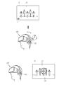
- FIG. 1B is a conceptual view of an HMD related to the present invention, viewed from one direction.
- the HMD 100 related to the present invention is formed to be worn on a head (or head, face, head) of a human body, and a frame part (case, housing, cover, etc.) for this purpose is provided. It may include.
- the frame portion may be formed of a flexible material to facilitate wearing.
- the frame part includes a first frame 101 and a second frame 102 of different materials.
- the first frame 101 serves to provide a space in which at least one of the components described with reference to FIG. 1A may be disposed
- the second frame 102 may include the first frame 101. It may serve to support (or fix) to be mounted on the head of the human body.
- the frame portion may be referred to as a body (or HMD body) or a body (or HMD body).
- the HMD body (or HMD body) may be understood as a concept of referring to the HMD 100 as at least one aggregate.
- the frame part is supported by the head, and provides a space for mounting various components.
- electronic components such as a camera 121, an output unit, a user input unit 123, a controller, and a sensing unit may be mounted on the first frame 101.
- the display unit 151 may be formed to cover at least one of the left and right eyes of the user (or face at least one of the left and right eyes of the user), and may be detachably formed.
- Electronic components such as the sound output unit 152 may be mounted on the second frame 102.
- the present invention is not limited thereto, and the components described with reference to FIG. 1A and the elements required for the HMD may be variously arranged in the first frame 101 and the second frame 102 by the user's selection.
- the controller 180 (see FIG. 1A) is configured to control various electronic components provided in the HMD 100.
- the controller 180 may be understood as a configuration corresponding to the controller 180 described with reference to FIG. 1A.
- the display unit 151 is mounted on the frame unit and serves to output screen information (eg, an image, an image, a video, etc.) in front of the user's eyes.
- screen information eg, an image, an image, a video, etc.
- the display unit 151 may be disposed to correspond to at least one of the left eye and the right eye so that screen information may be displayed in front of the user's eyes.
- the display unit 151 is positioned to cover both the left and right eyes so that the image can be output to both the left and right eyes of the user.
- the display unit 151 may project an image to the eyes of a user using a prism.
- the prism can be formed translucent so that the user can see the projected image together with the general field of view (the range the user sees through the eye) together.
- the HMD 100 may provide an augmented reality (AR) that displays a single image by superimposing a virtual image on a real image or a background using the characteristics of the display.
- AR augmented reality
- the display unit 151 of the HMD according to the present invention may be located inside the main body. Specifically, when the HMD is worn on the head of the user, the display unit 151 may be disposed at a position facing the user's eyes inside the HMD.
- the camera 121 is disposed adjacent to at least one of the left eye and the right eye, and is formed to capture an image of the front. Since the camera 121 is disposed to face the eye adjacent to the eye, the camera 121 may acquire a scene viewed by the user as an image.
- one camera 121 is provided, but is not necessarily limited thereto.
- a plurality of cameras 121 may be provided to acquire a stereoscopic image.
- the HMD 100 may include a user input unit for receiving a control command.
- the user input unit is mounted on one region of the main body of the HMD 100, and is based on a tactile manner in which the user operates while having a tactile feeling such as touch or push. Can receive the control command. That is, in this drawing, the user input unit 123 of the push and touch input method is provided in the frame unit.
- the user input unit of the HMD 100 may receive a preset gesture of the user with respect to the HMD 100, a preset movement of the main body of the HMD 100, and the like as a control command.
- the user input unit may include at least one sensor.
- the HMD 100 may include a gyro sensor or an acceleration sensor for detecting a movement such as rotation or tilting of the main body of the HMD 100.
- the user may further include a camera or an infrared sensor for detecting a predetermined gaze of the user as a preset gesture for the HMD 100 of the user.
- the controller may control at least one of the display unit and the sound output unit based on the control command.
- the HMD 100 may be provided with a microphone (not shown) for receiving sound and processing it as electrical voice data and a sound output unit 152 for outputting sound.
- the sound output unit 152 may be configured to transmit sound in a general sound output method or a bone conduction method. When the sound output unit 152 is implemented in a bone conduction manner, when the user wears the HMD 100, the sound output unit 152 is in close contact with the head and vibrates the skull to transmit sound.
- the HMD 100 may include at least one microphone (not shown) capable of detecting a sound event generated outside the HMD 100 in the body of the HMD 100.
- the microphone may detect a sound event generated outside of the HMD 100 that the user cannot hear while sound information is output from the sound output unit 152 of the HMD 100.
- the microphone may be configured as a directional microphone capable of identifying a location where the sound event occurs.
- the HMD according to the present invention may detect a sound event generated outside of the HMD using a microphone while sound information is output by the sound output unit. Then, the information on the occurrence of the sound event can be provided to the user using the HMD. For example, the HMD may output visual information indicating the occurrence of the sound event using a display unit. If screen information is being output to the display unit, the visual information may be output together with the screen information. Therefore, since the user is provided with information on a specific sound generated outside of the HMD, there is an effect of recognizing the external situation of the HMD even while using the HMD.
- FIGS. 2B and 2C are representative views for explaining the control method of the HMD according to the present invention.
- screen information may be output to the display unit of the HMD according to the present invention (S201).
- the screen information may include all kinds of screen information such as an execution screen and a standby screen according to execution of a specific function.
- sound information may be output to the sound output unit of the HMD according to the present invention (S202).
- the sound information may be output based on execution of a specific function or may be output based on output of the screen information.
- the sound information may be output independently of the screen information based on the execution of a specific application (for example, a music reproduction application).
- the sound information may be output based on the output of the moving picture information.
- the screen information may be video information 10, and sound information based on the output of the video information 10 may be output to the sound output unit 152. .
- the present invention is not limited thereto. That is, output of the screen information does not have to be premised on the display unit 151.
- a sound event generated outside the HMD may be detected by the microphone (S203).
- the sound event may include all kinds of sounds generated outside the HMD while the sound information is output.
- the sound event may include various kinds of sounds, such as a siren sound and a sound of an external electronic device operating.
- the sound event may be an event generated by a voice of a specific person, as shown in the second drawing of FIG. 2B.
- the controller 180 may output a graphic object indicating the occurrence of the sound event to the display unit based on the satisfaction of the preset sound event. have.
- the user input unit may be activated to receive a control command for controlling the display unit and the sound output unit (S204).
- the preset condition is a condition for determining a type of a sound event generated outside of the HMD, and may be a condition related to at least one of a decibel range of a preset sound, a waveform characteristic of a preset sound, and preset keyword information. have.
- the controller 180 may output the graphic object when a sound event having a specific size is generated. That is, when the sound event detected through the microphone is included in a predetermined decibel range, the graphic object corresponding to the sound event may be output.
- the controller 180 may determine whether preset keyword information is included in the sound event.
- the preset keyword information may include, for example, a person's name or a word having a specific meaning, and may be registered as various information according to a user's setting.
- the controller 180 may determine whether a characteristic of a waveform corresponding to the sound event corresponds to a preset waveform characteristic.
- the sound event may be generated by a voice of a specific person or by a performance of a specific instrument.
- the preset waveform characteristic may be stored in the memory as information corresponding to the specific person's voice or a specific musical instrument.
- the controller 180 may determine whether the predetermined condition is satisfied by comparing the amplitude, period, frequency, etc. of the waveform corresponding to the sound event with the amplitude, period, frequency, etc. of the preset waveform. If the characteristic such as amplitude, period, frequency, etc. of the waveform corresponding to the sound event corresponds to the amplitude, period, frequency, etc. of the preset waveform, the controller 180 satisfies the preset condition. It can be judged.
- the controller 180 may determine whether a waveform characteristic corresponding to the sound event corresponds to a waveform characteristic of a specific person previously stored. If it is determined that the voice information is the voice of the specific person, the controller 180 may determine that the sound event satisfies a preset condition.
- the controller 180 may output the graphic object to the display unit 151 based on the sound event satisfying a preset condition.
- the graphic object may include information regarding the sound event as visual information indicating the occurrence of the sound event.
- the graphic object may be an icon including information on the type of the sound event. That is, the graphic object may be an icon representing the size or content of the sound event, the origin of the sound event, and the like.
- the graphic object may include information about a location where the sound event occurred.
- the controller 180 can output the graphic object 1 to the area of the display unit 151 corresponding to the position where the sound event is generated.
- the controller 180 may activate the user input unit to receive a control command for changing an output state of at least one of the screen information and sound information.
- the control command input through the user input unit while the graphic object is output may be processed as an input for controlling at least one of the display unit 151 and the sound output unit 152.
- Control commands input through the user input unit may be of various kinds.
- the user input unit may be mounted in one area of the main body to receive a control command from the user through tactile input such as touch or push.
- the user input unit may generate the control command by detecting a preset gesture of the user (for example, a hand movement within a predetermined distance from the main body, a user's gaze, etc.) with respect to the main body. Can be input.
- the user input unit may include a proximity sensor or a camera for detecting the preset gesture.
- the user input unit may include at least one sensor for detecting the movement of the main body, and may receive a control command by detecting the movement of the main body.
- the controller 180 may process the movement of the main body of the HMD 100 detected by the user input unit as the control command.
- the controller 180 may change an output state of at least one of the screen information and sound information based on the control command.
- controller 180 may variously change the output state of the screen information and sound information based on the type of control command input through the user input unit.
- output of at least one of the screen information and sound information may be terminated, or other visual information may be superimposed on the screen information and output.
- the controller 180 may change and output the sound information to a preset size. An embodiment related to this will be described later with reference to FIGS. 4A and 4B.
- the HMD according to the present invention enables the user to recognize the external situation through the graphic object informing of the occurrence of the sound event even when the user does not hear the externally generated sound while the user is provided with the acoustic information.
- the graphic object for notifying the occurrence of the sound event is output based on satisfying a predetermined condition, limiting the notification to the sound that the user does not need to recognize, the specific external that the user needs to recognize You can optionally provide information only about the situation.
- the controller 180 may output the graphic object to the display unit 151 based on the sound event satisfying a preset condition.
- the graphic object may include information related to the sound event. More specifically, the information related to the sound event may include a type of the sound event, an occurrence size of the sound event, a location where the sound event occurs, and the like.
- the voice event may include information of a specific person corresponding to the voice information, information on contents or keywords included in the voice information, and the like.
- the graphic object may be output in various ways according to the information related to the sound event. That is, the graphic object may vary in position, size, shape, color, etc., output on the display unit 151 according to the sound event.
- 3A and 3B illustrate an embodiment of various output methods of the graphic object.
- the microphone of the HMD according to the present invention may be a directional microphone capable of selectively sensing only a narrow angle of sound coming from a specific direction.
- the HMD may be provided with a plurality of microphones so as to determine the position where the sound event occurs based on the HMD.
- the controller 180 can determine a location where the sound event is generated based on the HMD based on the analysis of the sound event.
- the controller 180 may determine the direction of the point where the sound event occurs among the left, right, front, and rear of the HMD main body based on a state in which the user wears the HMD. In addition, the controller 180 may determine the distance from the main body of the HMD to the point where the sound event is generated, based on the magnitude of the sound event detected.
- the controller 180 may display the display unit 151 corresponding to the location where the sound event is generated based on the satisfaction of a preset condition.
- the graphic object may be output in the region of.
- the graphic object 2a is output to the upper center of the screen information 10.
- the display unit 151 may be controlled.
- the graphic object 2b is output at the bottom center of the screen information 10.
- the display unit 151 may be controlled to be able to.
- the controller 180 can adjust the output size or color of the graphic object based on the distance to the point where the sound event occurs. For example, the controller 180 may control the display unit 151 so that the graphic object is larger as the distance to the point where the sound event occurs based on the position of the HMD approaches.
- the user since the output method of the graphic object is changed in the display unit 151 according to the occurrence position of the sound event, the user may roughly recognize the position at which the sound event occurs according to the output method of the graphic object. Can be.
- controller 180 can grasp information about a source of the sound event by using characteristics of a waveform corresponding to the sound event.
- the memory may store information about a waveform of a sound that can be compared with a characteristic of a waveform corresponding to the sound event.
- the information on the waveform stored in the memory may be waveform information for identifying the source of a sound event, such as waveform information corresponding to a voice of a specific person, waveform information about a sound of a specific instrument, and the like.
- the controller 180 may compare characteristics of the waveform, amplitude, frequency, period, etc. of the waveform corresponding to the sound event with the waveform stored in the memory.
- the source of the sound event may be grasped using information on the waveform corresponding to the sound event and information on the waveform corresponding to the sound event.
- the controller 180 may output an icon including information about a source of the sound event as the graphic object. For example, when a waveform corresponding to the sound event corresponds to waveform information of a specific person stored in the memory, as shown in FIG. 3B, the controller 180 displays the icon 3 representing the mommy. It may be output to the display unit 151.
- the user can grasp the source of the sound event occurrence by the graphic object.
- the controller 180 may control the display unit 151 and the sound output unit 152 based on various control commands input to the user input unit while the graphic object is output.
- the controller 180 may change the output state of the screen information based on the first control command when the first control command is input to the user input unit while the graphic object is output.
- the output state of the sound information may be changed based on the second control command.
- the first and second control commands may be input by tactile input such as touch or push or by detecting a preset gesture by at least one sensor.
- tactile input such as touch or push
- detecting a preset gesture by at least one sensor.
- 4A and 4B illustrate embodiments in which output of screen information and sound information are controlled differently according to the type of control command.
- a sound event may be generated from the outside.
- the controller 180 displays the graphic object 1 notifying the occurrence of the sound event based on the condition that the sound event satisfies a preset condition. Can be output to
- the controller 180 changes the output state of the screen information 10 based on the first control command.
- the first control command may be input by detecting a preset gesture (eye blinking gesture) by the user while the graphic object 1 is output as shown in the second drawing of FIG. 4A. .
- the controller 180 may control the display unit 151 to display detailed information about the sound event on at least part of the screen information.
- the detailed information of the sound event may be specific content of the constant information when the sound event includes content for delivering constant information.
- the sound event when the sound event includes a specific keyword, the sound event may be text information corresponding to the specific keyword.
- the controller 180 may output information included in the sound event to at least part of the screen information.
- the controller 180 may display the display unit 11 such that a screen 11a including a keyword of information included in the sound event and a specific image corresponding to the keyword overlaps at least a part of the screen information 10. 151 can be controlled.
- the controller 180 may output text information 11b corresponding to the sound event to at least part of the screen information.
- the controller 180 may acquire text information corresponding to the sound event by using a speech to text (STT) function.
- STT speech to text
- the HMD according to the present invention is based on the input of the control command in a state where a graphic object including brief information on the occurrence of the sound event (for example, the type, origin, location, etc. of the sound event) is output. More specific information about the sound event may be provided. Therefore, the user may be provided with more specific information about an external situation in relation to the sound event by using a simple gesture while executing a function using the HMD.
- a graphic object including brief information on the occurrence of the sound event for example, the type, origin, location, etc. of the sound event
- controller 180 may change an output state of the sound information according to a second control command input through the user input unit.
- a preset movement of the main body of the HMD 100 is performed. This can be detected.
- the second control command may be input as being sensed that the main body of the HMD is inclined by the user's nod gesture as shown in the second drawing of FIG. 4B.
- the controller 180 may control the sound output unit 152 to change the output size of the sound information.
- the output size of the sound information may be output as small or as large as a predetermined size.
- controller 180 may adjust the output size of the sound information in response to the size of the sound event detected by the microphone.
- the controller 180 may reduce the output size of the sound information by a preset ratio in response to the sound event size. If the sound event is continuously generated, the output size of the sound information is adjusted to correspond to the size of the sound event, so that the user can listen to the sound information and the sound event together.
- the controller 180 may perform recording on the sound event based on the occurrence of the sound event. In this case, the controller 180 can obtain more specific information on the sound event by using the recording data on which the sound event has been recorded. When the control command is input while the graphic object is output, the controller 180 can provide the user with detailed information on the sound event using the recording data.
- the controller 180 acquires text information corresponding to the recording data, and then outputs the text information to the display unit 151 or, together with the sound information, as shown in the third drawing of FIG. 4B.
- the sound output unit 152 may be controlled to output the recording data.
- Whether or not to record the sound event may vary according to a user's setting. That is, the user may set the recording to be performed on the premise that the sound event occurs. In addition, the user may set the recording of the sound event to be performed based on a specific input being applied while the graphic object is output.
- the user may end the output of the graphic object itself by inputting various control commands or may terminate the output of at least one of the screen information and the sound information.
- the user may input different control commands to change the output state of at least one of the screen information and the sound information which are previously executed in the HMD, so that the user may conveniently receive more specific information about the sound event.
- the controller 180 may independently control each of the screen information and sound information according to the type of the control command.
- the controller 180 can simultaneously control the output state of the screen information and sound information by one control command.
- the screen information may correspond to video information including a plurality of consecutive images changed over time, and the sound information may be output based on the output of the video information.
- the controller 180 may control the display unit 151 and the sound output unit 152 to change the output state of the video information based on a control command input to the user input unit.
- 5A, 5B, and 5C are diagrams illustrating an embodiment in which an output state of video information is changed based on a control command when video information is output.
- video information 10 may be output to the display unit 151, and sound information may be output based on the output of the video information 10.
- the controller 180 may output the graphic object 1 to the display unit 151.
- the controller 180 may stop the output of the video information 10. have.
- the controller 180 displays the video in a state in which one image output to the display unit 151 is output when the preset control command is input from among a plurality of images constituting the video information 10.
- the output of the information 10 can be stopped.
- the sound output unit 152 may be controlled to limit the output of the sound information when the output of the video information 10 is stopped.
- a preset first gesture (a gesture of moving the main body of the HMD left and right) may be detected through the user input unit.
- the controller 180 may control the output state of the video information 10 based on the preset first gesture.
- the controller 180 releases the output stop state of the video information 10 and reproduces the video information 10 again.
- the output unit 152 may be controlled.
- the controller 180 controls the display unit 151 to output the video information 10 from an image corresponding to the next order of the one image among a plurality of images constituting the video information 10. can do.
- the output of the graphic object 1 output to the display unit 151 may be terminated.
- controller 180 may control the sound output unit 152 to output sound information corresponding to an image corresponding to the next sequence of the one image based on the reproduction of the video information 10 again. have.
- the user may temporarily stop the output of the video information to check the sound event while watching the video information.
- the user may easily play back the video information by inputting a preset gesture.
- a second preset gesture when the user inputs a blinking gesture
- the controller 180 may control the display unit 151 and the sound output unit 152 to terminate the output of the video information based on the input of the preset second gesture.
- the display unit 151 may be switched to an inactive state.
- a preset standby screen may be output to the display unit 151 based on the end of the output of the video information.
- a third gesture set by the user input unit (as shown in the second drawing of FIG. 5C, the user wearing the main body of the HMD nods his head). By detecting the movement of the main body of the HMD).
- the controller 180 may control the display unit 151 and the sound output unit 152 so that the video information is reproduced again. However, the controller 180 may control the sound output unit 152 so that the sound information is output by a predetermined size smaller than the size that was output before the output of the video information was stopped.
- the controller 180 may stop the output of the screen information and the sound information simultaneously based on a control command input through the user input unit. Can be.
- the output state of the video information may be variously controlled based on various gestures applied through the user input unit while the output of the video information is stopped. Therefore, after checking the sound event while the output of the video information is stopped, the user may additionally input various gestures to select whether to continue playing the video information.
- the controller 180 may stop the output of the video information based on a sound event generated outside the HMD satisfying a specific condition among preset conditions while the video information is output to the HMD. .
- the controller 180 satisfies the specific condition when the sound event includes a predetermined specific keyword or when a waveform corresponding to the sound event corresponds to a waveform of a preset specific sound. You can judge.
- the controller 180 may stop the output of the video information and output the graphic object to the display unit 151.
- the output state of the video information may be controlled according to a control command input through a user input unit while the graphic object is output.
- 6A and 6B illustrate an embodiment related to a case where output of video information is stopped based on a specific sound event.
- video information 10 may be output to the display unit 151, and sound information may be output to the sound output unit 152 based on the output of the video information 10. .
- the controller 180 may determine whether the sound event satisfies a preset condition.
- the controller 180 may determine that the sound event satisfies the specific condition. In addition, the controller 180 may control the display unit 151 and the sound output unit 152 to stop the output of the video information 10.
- specific sound keyword information e.g, personal image
- controller 180 displays the graphic object 1 together with the one image being output to the display unit 151 when the output of the video information 10 is stopped among the plurality of images constituting the video information. You can print
- a predetermined control command may be input through a user input unit while the graphic object 1 is output.
- the controller 180 displays the video information 10 so that the video information 10 is played again.
- the unit 151 and the sound output unit 152 may be controlled.
- the controller 180 may control the display unit 151 to end the output of the graphic object 1 with the reproduction of the video information 10.
- the The controller 180 can record the sound event.
- the controller 180 may control the display unit 151 and the sound output unit 152 so that the video information 10 is reproduced together with recording of the sound event.
- the controller 180 may control the display unit 151 so that the information 2 for notifying the recording is displayed at the same time as the output of the graphic object is terminated.
- the controller 180 may stop the output of the video information on the basis of the sound event satisfying a predetermined specific condition. Therefore, when a sound event is generated that satisfies a predetermined condition (for example, when specific keyword information is included or voice information of a specific person), the user does not need to input a separate control command. You will be provided with the convenience of identifying it yourself.
- a predetermined condition for example, when specific keyword information is included or voice information of a specific person
- the output position of the graphic object on the display unit 151 may be determined by the position where the sound event occurs, as described above with reference to FIG. 3A.
- the controller 180 may determine the intention of the user based on the control command.
- the output state of the screen information and sound information may be changed according to the intention of the user. This will be described with reference to FIGS. 7A and 7B.
- FIG. 7A and 7B illustrate an embodiment of controlling output states of screen information and sound information according to the type of control command when a graphic object is output in correspondence with a location of a sound event.
- a sound event may be generated on the right side of a user wearing the main body of the HMD based on the main body of the HMD.
- the controller 180 may determine the occurrence position of the sound event by analyzing the sound event detected by the microphone.
- the controller 180 may control the display unit 151 such that the graphic object 1 is output to an area of the display unit 151 corresponding to the position where the sound event is generated. For example, as shown in the second drawing of FIG. 7A, the graphic object 1 may be output to an area on the right side of the display unit 151 in a direction in which the user looks at the display unit 151.
- a control command for moving the main body of the HMD in a direction away from the position where the sound event is generated may be detected by the user input unit.
- the user may input the control command in a gesture of turning his head in a left direction while wearing the HMD 100.
- the controller 180 may determine the user's intention to maintain the output state of the screen information and sound information.
- the controller 180 may control the display unit 151 to maintain the output state of the screen information and sound information and to terminate only the output of the graphic object 1 based on the input of the control command. Can be.
- the movement of the HMD 100 (the gesture in which the user wearing the HMD turns his head to the right) is detected by the user input unit toward the position where the sound event is generated.
- the controller 180 may determine a user's intention to check information related to the sound event.
- the controller 180 can change the output state of the screen information and sound information based on the input of the control command. For example, when the screen information and the sound information are output based on reproduction of specific video information, the controller 180 may stop the output of the video information.
- the controller 180 may activate a camera mounted on the main body of the HMD based on the input of the control command. That is, the controller 180 may control the camera to perform shooting of a preset angle of view range of the camera based on the movement of the main body of the HMD toward the position where the sound event occurs.
- controller 180 may control the display unit 151 such that the preview screen 12 captured by the camera is output together with the video information 10 where the output is stopped.
- the user may be provided with detailed visual information on the external situation while maintaining the wearing of the HMD by moving the main body of the HMD toward the position where the sound event occurs.
- a user who wears the main body of the HMD while the graphic object is output at a position corresponding to the position where the sound event occurs on the display unit 151 may be connected to the main body of the HMD.
- the intention of the user can be predicted based on the moving direction. Accordingly, the controller 180 may perform control in accordance with the intention of the user, such as maintaining or terminating a function previously executed in the HMD.
- the HMD may include a camera in the main body of the HMD, and the camera may photograph a subject included in a preset angle of view. As described above in the embodiment of FIG. 7B, the camera may be activated based on an input of a specific control command to perform photographing. In addition, the controller 180 may output the preview screen photographed by the camera to the display unit 151.
- FIG. 8 is a view related to an embodiment of providing a preview screen photographed based on an input of a control command.
- the video information 10 is output to the display unit 151, and the sound information is output to the sound output unit 152 based on the output of the video information 10. Can be.
- the controller 180 may output the graphic object based on the sound event satisfies a preset condition.
- the controller 180 may determine the output position of the graphic object on the display unit 151 after analyzing the occurrence position of the sound event detected by the microphone. That is, as shown in the second drawing of FIG. 8, the graphic object 4 may be output at the top center of the display unit 151 based on the location of the sound event generated in front of the HMD.
- the controller 180 may activate the camera based on the preset control command.
- the controller 180 may determine whether the preset control command is an input related to a generation position of the sound event.
- the input associated with the occurrence position of the sound event may be an input in which the main body of the HMD moves so that the direction of the front surface of the main body of the HMD corresponds to the position where the sound event occurs.
- the controller 180 moves the main body by the user (nod gesture) as shown in FIG. 8. It is possible to determine whether the front of the main body toward the direction in which the sound event occurs.
- the controller 180 activates the camera when an input of the preset control command is applied by the movement of the main body of the HMD, and the front of the main body faces the position where the sound event is generated by the movement. can do.
- the controller 180 may output the preview screen captured by the camera to the display unit 151 with the activation of the camera. At this time, the controller 180 stops the output of the video information based on the input of the preset control command, and displays the display unit 151 such that the preview screen is output together with the stopped video screen. Can be controlled.
- the preview screen may be output to the display unit 151 in various ways.
- the output may be overlaid on at least a portion of the stopped video screen or may be output on a portion of the video screen in a picture in picture (PIP) manner as shown in the third drawing of FIG.
- PIP picture in picture
- the controller 180 may provide the preview screen together with the video information being played without stopping output of the video information according to a setting.
- the controller 180 may front the main body based on the input.
- the direction of the heading may be determined, and the activation of the camera may be determined. If the front surface of the main body does not face the location where the sound event is generated, notification information may be provided to the user.
- the camera is always in an active state, and the controller 180 may output a preview screen captured by the camera based on the input of the control command.
- the user may provide a user with a photographing screen for the location where the sound event occurs, thereby providing the user with more detailed visual information on the sound event. Can be.
- the HMD according to the present invention may limit the notification output (for example, the output of the graphic object for notifying the occurrence of the sound event) for the external situation based on a specific setting such as an interference prevention mode.
- a specific setting such as an interference prevention mode.
- FIG. 9 is a diagram illustrating an embodiment related to outputting a notification of an external event generated while using the HMD when the use of the HMD is terminated.
- the video information 10 is output to the display unit 151, and the sound is output from the outside while the sound information is output through the sound output unit 152.
- An event may occur.
- the HMD may be set an interruption prevention mode for limiting the event notification generated during the execution of a specific function by the user.
- the controller 180 may perform recording on the sound event detected by the microphone.
- the controller 180 may display information on the recording in one region of the video information 10.
- the controller 180 may provide only a notification regarding whether to perform the recording while maintaining the output of the video information. Thereafter, as shown in the third drawing of FIG. 9, when the reproduction of the video information is completed, the controller 180 outputs a message 10c requesting confirmation of the recording data for the sound event to the display unit 151. can do.
- the user can be provided with information on an external situation that cannot be confirmed during the use of the HMD without being interrupted in the use of the HMD.
- the HMD detects an external sound event through a microphone while the sound information is being output and informs the user, so that the user can be provided with information on an external situation that is difficult to recognize due to the execution of a specific function.
- the occurrence of the sound event is provided to the user through a graphic object and the graphic object includes information about the sound event, when the graphic object is output to the display unit, the user recognizes an external situation. can do.
- the user is provided with the convenience of variously controlling the execution state of a specific function that is being executed in relation to an externally generated sound event according to various control commands.
- the present invention described above can be embodied as computer readable codes on a medium in which a program is recorded.
- the computer-readable medium includes all kinds of recording devices in which data that can be read by a computer system is stored. Examples of computer-readable media include hard disk drives (HDDs), solid state disks (SSDs), silicon disk drives (SDDs), ROMs, RAMs, CD-ROMs, magnetic tapes, floppy disks, optical data storage devices, and the like. This also includes implementations in the form of carrier waves (eg, transmission over the Internet).
- the computer may also include a controller 180 of the HMD. Accordingly, the above detailed description should not be construed as limiting in all aspects and should be considered as illustrative. The scope of the invention should be determined by reasonable interpretation of the appended claims, and all changes within the equivalent scope of the invention are included in the scope of the invention.
Abstract
When a sound event generated outside has been sensed while a specific function is executed and the sound event satisfies a specific condition, an HMD according to the present invention may provide a notification therefor to a user. More specifically, the HMD comprises: a display unit formed to output screen information; an acoustic output unit for outputting acoustic information; a microphone for sensing the sound event generated outside of the HMD in a state in which the acoustic information is output; a user input unit for receiving an input of a control command for controlling the display unit and the acoustic output unit; and a control unit for controlling the display unit to output a graphic object notifying of the generation of the sound event when the sound event sensed through the microphone satisfies a pre-configured condition, and activating the user input unit in order to change an output state of at least one of the screen information and the acoustic information while the graphic object is output.
Description
본 발명은 외부에서 발생된 이벤트에 대한 알림을 제공할 수 있는 헤드 마운티드 디스플레이(Head Mounted Display, 이하 'HMD'라 함)에 관한 것이다. The present invention relates to a head mounted display (hereinafter referred to as 'HMD') capable of providing a notification about an externally generated event.
헤드 마운티드 디스플레이(HMD)란 안경처럼 사용자의 헤드에 착용되어 사용자가 영상(컨텐츠)을 볼 수 있도록 하는 각종 영상 표시 장치를 말한다. 디지털 디바이스의 경량화 및 소형화 추세에 따라, 다양한 웨어러블 컴퓨터(Wearable Computer)가 개발되고 있으며, 상기 HMD 또한 널리 사용되고 있다. HMD는 단순한 디스플레이 기능을 넘어 증강 현실 기술, N 스크린 기술 등과 조합되어 사용자에게 다양한 편의를 제공할 수 있다.A head mounted display (HMD) refers to various image display devices that are worn on a user's head like glasses to allow a user to view an image (content). In accordance with the trend of light weight and miniaturization of digital devices, various wearable computers have been developed, and the HMD is also widely used. The HMD can be combined with augmented reality technology, N screen technology, etc., beyond simple display functions to provide various conveniences to the user.
최근에는, HMD의 사용이 증가함에 따라, 이동 단말기에서 실행될 수 있는 다양한 기능의 실행이 가능한 HMD가 구현되고 있다. 예를 들어, 상기 이동 단말기에서 특정 기능의 실행에 근거하여 특정 시각정보나 청각정보를 제공하는 것과 마찬가지로 상기 HMD에서도 상기 특정 기능의 실행에 근거하여 특정 시각정보 및 청각정보의 제공이 가능해졌다.Recently, as the use of the HMD increases, an HMD capable of executing various functions that can be executed in a mobile terminal has been implemented. For example, similarly to providing specific visual or auditory information based on the execution of a specific function in the mobile terminal, the HMD can provide specific visual and auditory information based on the execution of the specific function.
또한, 상기 HMD는 사용자의 두부에 착용된다는 특수성으로 인하여, 상기 HMD를 이용하는 사용자가 특정 시각정보나 청각정보를 제공받는 동안은 외부(Real World)와 효과적으로 단절될 수 있어, 다양한 기능을 보다 현실감 있게 사용자에게 제공할 수 있다.In addition, due to the specificity that the HMD is worn on the head of the user, the user using the HMD can be effectively disconnected from the real world while receiving specific visual or auditory information, thereby realizing various functions more realistically. Can be provided to the user.
다만, 이로 인하여, 상기 HMD를 이용하는 동안 사용자는 외부에서 발생된 상황에 대해서는 인지하기가 어려웠다. 특히, 위급 상황과 같은 특정 이벤트가 외부에서 발생되어도 사용자는 상기 HMD의 이용을 종료하지 않는 이상 상기 특정 이벤트 발생을 알기 어려웠다.However, due to this, it is difficult for a user to recognize an externally generated situation while using the HMD. In particular, even when a specific event such as an emergency occurs outside, it is difficult for a user to know that the specific event occurs unless the user terminates the use of the HMD.
이에, 본 발명의 일 목적은, 일 기능이 실행중인 상태에서 외부에서 특정 이벤트가 발생된 경우, 상기 기능의 실행을 유지하면서 상기 특정 이벤트 발생을 알릴 수 있는 HMD 및 그것의 제어방법을 제공하는 것이다.Accordingly, an object of the present invention is to provide an HMD capable of notifying the occurrence of the specific event while maintaining the execution of the function and a control method thereof when a specific event is generated externally while a function is being executed. .
이와 같은 본 발명의 목적을 달성하기 위하여, 사용자의 두부에 착용 가능하도록 형성되는 HMD는, 화면정보를 출력하도록 형성되는 디스플레이부, 음향정보를 출력하는 음향 출력부, 상기 음향정보가 출력되는 상태에서, 상기 HMD의 외부에서 발생된 소리 이벤트를 감지하는 마이크, 상기 디스플레이부 및 음향 출력부의 제어를 위한 제어명령을 입력받는 사용자 입력부 및 상기 마이크를 통하여 감지된 소리 이벤트가 기 설정된 조건을 만족하는 것에 근거하여 상기 소리 이벤트의 발생을 알리는 그래픽 객체가 출력되도록 상기 디스플레이부를 제어하고, 상기 그래픽 객체가 출력되는 동안, 상기 화면정보 및 음향정보 중 적어도 하나의 출력상태를 변경하기 위하여 상기 사용자 입력부를 활성화하는 제어부를 포함할 수 있다.In order to achieve the object of the present invention, the HMD is formed to be worn on the head of the user, the display unit is formed to output the screen information, the sound output unit for outputting the sound information, in the state that the sound information is output And a microphone for detecting a sound event generated outside of the HMD, a user input unit for receiving control commands for controlling the display unit, and a sound output unit, and a sound event detected through the microphone satisfying a preset condition. A control unit to control the display unit to output a graphic object indicating the occurrence of the sound event, and to activate the user input unit to change an output state of at least one of the screen information and sound information while the graphic object is output. It may include.
일 실시 예에 있어서, 상기 기 설정된 조건은, 기 설정된 소리의 데시벨 범위, 기 설정된 소리의 파형 특성 및 기 설정된 키워드 정보 중 적어도 하나와 관련될 수 있다.In an embodiment, the preset condition may be related to at least one of a decibel range of a preset sound, a waveform characteristic of a preset sound, and preset keyword information.
일 실시 예에 있어서, 상기 제어부는, 상기 사용자 입력부를 통하여 입력되는 상기 제어명령의 종류에 따라 상기 화면정보 및 음향정보 중 적어도 하나의 출력상태를 서로 다르게 변경할 수 있다.According to an embodiment, the controller may change the output state of at least one of the screen information and the sound information differently according to the type of the control command input through the user input unit.
일 실시 예에 있어서, 상기 제어부는, 상기 사용자 입력부를 통하여 기 설정된 제1 제어명령이 입력되면, 상기 화면정보의 적어도 일부에 상기 소리 이벤트에 관한 상세 정보가 표시되도록 상기 디스플레이부를 제어하고, 상기 사용자 입력부를 통하여 기 설정된 제2 제어명령이 입력되면, 상기 음향정보의 출력 크기가 변경되도록 상기 음향 출력부를 제어할 수 있다.According to an embodiment of the present disclosure, when a preset first control command is input through the user input unit, the controller controls the display unit to display detailed information about the sound event on at least a portion of the screen information, and the user When the preset second control command is input through the input unit, the sound output unit may be controlled to change the output size of the sound information.
일 실시 예에 있어서, 상기 제어부는, 상기 소리 이벤트가 음성 정보인 경우, 상기 기 설정된 제1 제어명령이 입력되는 것에 근거하여 상기 화면정보의 적어도 일부에 상기 음성 정보에 대응되는 텍스트 정보가 표시되도록 상기 디스플레이부를 제어할 수 있다.According to an embodiment of the present disclosure, when the sound event is voice information, the controller may display text information corresponding to the voice information on at least a portion of the screen information based on the input of the preset first control command. The display unit may be controlled.
일 실시 예에 있어서, 상기 제어부는, 상기 기 설정된 제2 제어명령이 입력되는 것에 근거하여, 상기 음향정보가 상기 소리 이벤트가 감지된 크기에 대응하여 기 설정된 비율만큼 작게 출력되도록 상기 음향 출력부를 제어할 수 있다.According to an embodiment, the controller may control the sound output unit to output the sound information to be smaller by a preset ratio in response to the detected size of the sound event based on the input of the second control command. can do.
일 실시 예에 있어서, 상기 화면정보가 시간의 흐름에 따라 변경되는 연속적인 복수의 이미지를 포함하는 동영상 정보에 해당하고, 상기 음향정보가 상기 동영상 정보의 출력에 근거하여 출력되는 경우, 상기 제어부는, 상기 소리 이벤트가 상기 기 설정된 조건 중 특정 조건을 만족하는 것에 근거하여 상기 동영상 정보에 대한 출력이 정지되도록 상기 디스플레이부 및 음향 출력부를 제어할 수 있다.According to an embodiment of the present disclosure, when the screen information corresponds to moving picture information including a plurality of consecutive images changed over time, and the sound information is output based on the output of the moving picture information, the controller may include: The display unit and the sound output unit may be controlled to stop the output of the video information based on the sound event satisfying a specific condition among the preset conditions.
일 실시 예에 있어서, 상기 그래픽 객체는, 상기 복수의 이미지 중 상기 동영상 정보의 출력이 정지되는 때에 상기 디스플레이부에 출력된 일 이미지와 함께 출력되고, 상기 제어부는, 상기 사용자 입력부를 통하여 입력되는 상기 제어명령의 종류에 따라 상기 동영상 정보의 출력상태가 변경되도록 상기 디스플레이부 및 음향 출력부를 제어할 수 있다.The graphic object may be output together with one image output to the display unit when the output of the video information among the plurality of images is stopped, and the controller may be input through the user input unit. The display unit and the audio output unit may be controlled to change the output state of the video information according to the type of control command.
일 실시 예에 있어서, 상기 제어부는, 상기 사용자 입력부를 통하여 제1 제어명령이 입력되면 상기 그래픽 객체의 출력을 종료시키고, 상기 동영상 정보가 상기 일 이미지의 다음 순서에 해당하는 이미지부터 재생되도록 상기 디스플레이부 및 음향 출력부를 제어하고, 상기 사용자 입력부를 통하여 제2 제어명령이 입력되면 상기 동영상 정보에 대한 출력이 종료되도록 상기 디스플레이부 및 음향 출력부를 제어할 수 있다.According to an embodiment of the present disclosure, when the first control command is input through the user input unit, the controller may terminate the output of the graphic object and display the video information so that the video information is reproduced from an image corresponding to the next sequence of the one image. The display unit and the audio output unit may be controlled, and the display unit and the audio output unit may be controlled to terminate the output of the video information when a second control command is input through the user input unit.
일 실시 예에 있어서, 상기 제어부는, 상기 소리 이벤트가 상기 기 설정된 조건 중 특정 조건을 만족하는 것에 근거하여, 상기 음향정보의 출력 크기가 감소하도록 상기 음향 출력부를 제어할 수 있다.In an embodiment, the controller may control the sound output unit to reduce the output size of the sound information based on the sound event satisfying a specific condition among the preset conditions.
일 실시 예에 있어서, 상기 제어부는, 상기 음향정보의 출력 크기가 감소된 상태에서, 상기 사용자 입력부를 통하여 기 설정된 제어명령이 입력되면, 상기 소리 이벤트에 대한 녹음을 수행하고, 상기 녹음 수행을 알리는 정보가 상기 화면정보의 일 영역에 출력되도록 상기 디스플레이부를 제어할 수 있다.According to an embodiment of the present disclosure, when a preset control command is input through the user input unit while the output size of the sound information is reduced, the controller records the sound event and notifies the recording. The display unit may be controlled to output information to one area of the screen information.
일 실시 예에 있어서, 상기 제어부는, 상기 소리 이벤트의 분석에 근거하여 상기 소리 이벤트가 발생된 위치를 파악하고, 상기 그래픽 객체가 상기 소리 이벤트가 발생된 위치에 대응되는 상기 디스플레이부상의 영역에 출력되도록 상기 디스플레이부를 제어할 수 있다.In one embodiment, the control unit, based on the analysis of the sound event to determine the location where the sound event occurred, and outputs the graphic object to the area on the display unit corresponding to the location where the sound event occurred. The display unit may be controlled to be controlled.
일 실시 예에 있어서, 상기 HMD의 본체에 장착되어, 상기 HMD의 외부에 대한 촬영을 수행하는 카메라를 더 포함하고, 상기 제어부는, 상기 사용자 입력부를 통하여 특정 제어명령이 입력되는 것에 근거하여 상기 카메라를 활성화할 수 있다.In one embodiment, the camera is mounted on the main body of the HMD, and further comprises a camera for taking a picture of the outside of the HMD, the control unit, the camera based on a specific control command is input through the user input unit Can be activated.
일 실시 예에 있어서, 상기 사용자 입력부는, 상기 HMD의 본체의 움직임을 감지하는 적어도 하나의 센서를 포함하고, 상기 특정 제어명령은, 상기 적어도 하나의 센서에 의하여 상기 HMD의 본체가 상기 소리 이벤트가 발생된 위치를 향하여 움직이는 것이 감지되는 것에 근거하여 입력될 수 있다.In one embodiment, the user input unit, at least one sensor for detecting the movement of the main body of the HMD, the specific control command, the at least one sensor by the main body of the HMD is the sound event Movement towards the generated position may be input based on being detected.
일 실시 예에 있어서, 상기 제어부는, 상기 카메라에 의하여 촬영된 프리뷰 화면이 상기 화면정보의 적어도 일부에 중첩되어 출력되도록 상기 디스플레이부를 제어할 수 있다.In one embodiment, the controller may control the display unit such that the preview screen shot by the camera is superimposed on at least a portion of the screen information.
본 발명의 일 실시 예에 따른 HMD의 제어방법은, 디스플레이부에 화면정보를 출력하는 단계, 음향 출력부에 음향정보를 출력하는 단계, 상기 음향정보가 출력되는 상태에서, 상기 HMD의 외부에서 발생된 소리 이벤트를 감지하는 단계, 상기 감지된 소리 이벤트가 기 설정된 조건을 만족하는 경우, 상기 소리 이벤트의 발생을 알리는 그래픽 객체를 상기 디스플레이부에 출력하는 단계 및 상기 그래픽 객체가 출력되는 동안 상기 화면정보 및 음향정보 중 적어도 하나의 출력상태 변경을 위하여, 상기 디스플레이부 및 음향 출력부의 제어를 위한 제어명령을 입력받는 사용자 입력부를 활성화하는 단계를 포함할 수 있다.The control method of the HMD according to an embodiment of the present invention, outputting the screen information on the display unit, outputting the sound information to the sound output unit, in the state in which the sound information is output, generated outside the HMD Detecting a sound event, outputting a graphic object indicating the occurrence of the sound event to the display unit when the detected sound event satisfies a preset condition, and the screen information while the graphic object is output. And activating a user input unit for receiving a control command for controlling the display unit and the sound output unit to change the output state of at least one of the sound information.
일 실시 예에 있어서, 상기 기 설정된 조건은, 기 설정된 소리의 데시벨 범위, 기 설정된 소리의 파형 특성 및 기 설정된 키워드 정보 중 적어도 하나와 관련될 수 있다.In an embodiment, the preset condition may be related to at least one of a decibel range of a preset sound, a waveform characteristic of a preset sound, and preset keyword information.
일 실시 예에 있어서, 상기 그래픽 객체가 출력되는 동안 상기 사용자 입력부를 통하여 제어명령이 입력되면, 상기 제어명령의 종류에 근거하여 상기 화면정보 및 음향정보 중 적어도 하나의 출력상태를 서로 다르게 변경하는 단계를 더 포함할 수 있다.According to an embodiment of the present disclosure, when a control command is input through the user input unit while the graphic object is output, changing at least one output state of the screen information and sound information differently based on the type of the control command. It may further include.
일 실시 예에 있어서, 상기 화면정보 및 음향정보 중 적어도 하나의 출력상태를 서로 다르게 변경하는 단계는, 상기 사용자 입력부를 통하여 제1 제어명령이 입력되면 상기 화면정보의 적어도 일부에 상기 소리 이벤트에 관한 상세 정보를 표시하고, 상기 사용자 입력부를 통하여 제2 제어명령이 입력되면 상기 음향정보의 출력 크기를 변경할 수 있다.According to an embodiment, the step of changing the output state of at least one of the screen information and the sound information differently may be related to the sound event to at least a portion of the screen information when a first control command is input through the user input unit. Detailed information may be displayed and an output size of the sound information may be changed when a second control command is input through the user input unit.
일 실시 예에 있어서, 상기 그래픽 객체가 상기 디스플레이부에 출력되는 단계는, 상기 소리 이벤트의 분석에 근거하여 상기 소리 이벤트가 발생된 위치를 파악하고, 상기 소리 이벤트가 발생된 위치에 대응되는 상기 디스플레이부의 영역에 상기 그래픽 객체가 출력될 수 있다.In an embodiment, the outputting of the graphic object to the display unit may include: identifying a location where the sound event occurs based on an analysis of the sound event, and displaying the display corresponding to the location where the sound event occurs. The graphic object may be output in the negative area.
본 발명에 따르면, 상기 HMD는 음향정보가 출력되는 중에 마이크를 통하여 외부 소리 이벤트를 감지하고 이를 사용자에게 알림으로써, 사용자는 특정 기능의 실행으로 인하여 인지하기 어려운 외부 상황에 대한 정보를 제공받을 수 있다. 여기에서, 상기 소리 이벤트의 발생은 그래픽 객체를 통하여 사용자에게 제공되고 상기 그래픽 객체는 상기 소리 이벤트에 관한 정보를 포함하기 때문에, 상기 디스플레이부에 상기 그래픽 객체가 출력되면 사용자는 대략적으로 외부 상황을 인지할 수 있다. According to the present invention, the HMD detects an external sound event through a microphone while the sound information is being output and informs the user, so that the user can be provided with information on an external situation that is difficult to recognize due to the execution of a specific function. . Here, since the occurrence of the sound event is provided to the user through a graphic object and the graphic object includes information about the sound event, when the graphic object is output to the display unit, the user recognizes an external situation. can do.
또한, 상기 그래픽 객체가 출력된 상태에서, 사용자는 다양한 제어명령에 따라, 외부에서 발생된 소리 이벤트와 관련하여 기 실행중이던 특정 기능의 실행상태를 다양하게 제어할 수 있는 편의를 제공받는다.In addition, in the state where the graphic object is output, the user is provided with the convenience of variously controlling the execution state of a specific function that is being executed in relation to an externally generated sound event according to various control commands.
도 1a는 본 발명과 관련된 HMD를 설명하기 위한 블록도이다.1A is a block diagram illustrating an HMD related to the present invention.
도 1b는 본 발명과 관련된 HMD를 일 방향에서 바라본 개념도이다.Figure 1b is a conceptual view of the HMD associated with the present invention from one direction.
도 2a는 본 발명에 따른 HMD의 제어방법에 관한 순서도이고, 도 2b 및 도 2c는 본 발명에 따른 HMD의 제어방법을 설명하기 위한 대표도이다.2A is a flowchart illustrating a control method of the HMD according to the present invention, and FIGS. 2B and 2C are representative views for explaining the control method of the HMD according to the present invention.
도 3a 및 도 3b는 상기 그래픽 객체의 다양한 출력방식에 대한 실시 예를 도시한 도면이다.3A and 3B illustrate an embodiment of various output methods of the graphic object.
도 4a 및 도 4b는 제어명령의 종류에 따라 화면정보 및 음향정보의 출력이 서로 다르게 제어되는 것과 관련된 실시 예를 도시한 도면이다.4A and 4B illustrate embodiments in which output of screen information and sound information are controlled differently according to the type of control command.
도 5a, 도 5b 및 도 5c는 동영상 정보가 출력된 경우, 제어명령에 근거하여 동영상 정보의 출력상태가 변경되는 것과 관련된 실시 예를 도시한 도면이다.5A, 5B, and 5C are diagrams illustrating an embodiment in which an output state of video information is changed based on a control command when video information is output.
도 6a 및 도 6b는 특정 소리 이벤트에 근거하여 동영상 정보의 출력이 정지된 경우와 관련된 실시 예를 도시한 도면이다.6A and 6B illustrate an embodiment related to a case where output of video information is stopped based on a specific sound event.
도 7a 및 도 7b는 소리 이벤트의 발생 위치에 대응하여 그래픽 객체가 출력된 경우, 제어명령의 종류에 따라 화면정보 및 음향정보의 출력상태를 제어하는 실시 예를 도시한 도면이다.7A and 7B illustrate an embodiment of controlling output states of screen information and sound information according to the type of control command when a graphic object is output in correspondence with a location of a sound event.
도 8은 제어명령의 입력에 근거하여 촬영된 프리뷰 화면을 제공하는 실시 예와 관련된 도면이다.8 is a view related to an embodiment of providing a preview screen photographed based on an input of a control command.
도 9는 상기 HMD의 이용 중 발생된 외부 이벤트에 대한 알림을 상기 HMD의 이용이 종료된 때에 출력하는 것과 관련된 실시 예를 도시한 도면이다.FIG. 9 is a diagram illustrating an embodiment related to outputting a notification of an external event generated while using the HMD when the use of the HMD is terminated.
이하, 첨부된 도면을 참조하여 본 명세서에 개시된 실시 예를 상세히 설명하되, 도면 부호에 관계없이 동일하거나 유사한 구성요소는 동일한 참조 번호를 부여하고 이에 대한 중복되는 설명은 생략하기로 한다. 이하의 설명에서 사용되는 구성요소에 대한 접미사 "모듈" 및 "부"는 명세서 작성의 용이함만이 고려되어 부여되거나 혼용되는 것으로서, 그 자체로 서로 구별되는 의미 또는 역할을 갖는 것은 아니다. 또한, 본 명세서에 개시된 실시 예를 설명함에 있어서 관련된 공지 기술에 대한 구체적인 설명이 본 명세서에 개시된 실시 예의 요지를 흐릴 수 있다고 판단되는 경우 그 상세한 설명을 생략한다. 또한, 첨부된 도면은 본 명세서에 개시된 실시 예를 쉽게 이해할 수 있도록 하기 위한 것일 뿐, 첨부된 도면에 의해 본 명세서에 개시된 기술적 사상이 제한되지 않으며, 본 발명의 사상 및 기술 범위에 포함되는 모든 변경, 균등물 내지 대체물을 포함하는 것으로 이해되어야 한다. Hereinafter, embodiments of the present disclosure will be described in detail with reference to the accompanying drawings, and the same or similar components are denoted by the same reference numerals regardless of the reference numerals, and redundant description thereof will be omitted. The suffixes "module" and "unit" for components used in the following description are given or used in consideration of ease of specification, and do not have distinct meanings or roles from each other. In addition, in describing the embodiments disclosed herein, when it is determined that the detailed description of the related known technology may obscure the gist of the embodiments disclosed herein, the detailed description thereof will be omitted. In addition, the accompanying drawings are intended to facilitate understanding of the embodiments disclosed herein, but are not limited to the technical spirit disclosed herein by the accompanying drawings, all changes included in the spirit and scope of the present invention. It should be understood to include equivalents and substitutes.
제1, 제2 등과 같이 서수를 포함하는 용어는 다양한 구성요소들을 설명하는데 사용될 수 있지만, 상기 구성요소들은 상기 용어들에 의해 한정되지는 않는다. 상기 용어들은 하나의 구성요소를 다른 구성요소로부터 구별하는 목적으로만 사용된다.Terms including ordinal numbers such as first and second may be used to describe various components, but the components are not limited by the terms. The terms are used only for the purpose of distinguishing one component from another.
어떤 구성요소가 다른 구성요소에 "연결되어" 있다거나 "접속되어" 있다고 언급된 때에는, 그 다른 구성요소에 직접적으로 연결되어 있거나 또는 접속되어 있을 수도 있지만, 중간에 다른 구성요소가 존재할 수도 있다고 이해되어야 할 것이다. 반면에, 어떤 구성요소가 다른 구성요소에 "직접 연결되어" 있다거나 "직접 접속되어" 있다고 언급된 때에는, 중간에 다른 구성요소가 존재하지 않는 것으로 이해되어야 할 것이다.When a component is referred to as being "connected" or "connected" to another component, it may be directly connected to or connected to that other component, but it may be understood that other components may be present in between. Should be. On the other hand, when a component is said to be "directly connected" or "directly connected" to another component, it should be understood that there is no other component in between.
단수의 표현은 문맥상 명백하게 다르게 뜻하지 않는 한, 복수의 표현을 포함한다. Singular expressions include plural expressions unless the context clearly indicates otherwise.
본 출원에서, "포함한다" 또는 "가지다" 등의 용어는 명세서상에 기재된 특징, 숫자, 단계, 동작, 구성요소, 부품 또는 이들을 조합한 것이 존재함을 지정하려는 것이지, 하나 또는 그 이상의 다른 특징들이나 숫자, 단계, 동작, 구성요소, 부품 또는 이들을 조합한 것들의 존재 또는 부가 가능성을 미리 배제하지 않는 것으로 이해되어야 한다.In this application, the terms "comprises" or "having" are intended to indicate that there is a feature, number, step, operation, component, part, or combination thereof described in the specification, and one or more other features. It is to be understood that the present invention does not exclude the possibility of the presence or the addition of numbers, steps, operations, components, components, or a combination thereof.
본 명세서에서 설명되는 HMD에는 웨어러블 디바이스(wearable device, 예를 들어, 글래스형 단말기 (smart glass)) 등이 포함될 수 있다.The HMD described herein may include a wearable device (eg, a smart glass).
그러나, 본 명세서에 기재된 실시 예에 따른 구성은 HMD에만 적용 가능한 경우를 제외하면, 휴대폰, 스마트 폰(smart phone), 노트북 컴퓨터(laptop computer), 디지털방송용 단말기, PDA(personal digital assistants), PMP(portable multimedia player), 네비게이션, 슬레이트 PC(slate PC), 태블릿 PC(tablet PC), 울트라북(ultrabook), 워치형 단말기 (smartwatch) 등과 같은 이동 단말기에도 적용될 수 있음을 본 기술분야의 당업자라면 쉽게 알 수 있을 것이다.However, the configuration according to the embodiment described in the present specification is a mobile phone, a smart phone, a laptop computer, a digital broadcasting terminal, personal digital assistants (PDA), and PMP (except when applicable only to the HMD). Those skilled in the art will readily appreciate that the present invention can be applied to mobile terminals such as portable multimedia player, navigation, slate PC, tablet PC, ultrabook, and smartwatch. Could be.
도 1a를 참조하면, 도 1a는 본 발명과 관련된 HMD를 설명하기 위한 블록도이다.Referring to FIG. 1A, FIG. 1A is a block diagram illustrating an HMD related to the present invention.
상기 HMD(100)는 무선 통신부(110), 입력부(120), 센싱부(140), 출력부(150), 인터페이스부(160), 메모리(170), 제어부(180) 및 전원 공급부(190) 등을 포함할 수 있다. 도 1a에 도시된 구성요소들은 HMD를 구현하는데 있어서 필수적인 것은 아니어서, 본 명세서 상에서 설명되는 HMD는 위에서 열거된 구성요소들 보다 많거나, 또는 적은 구성요소들을 가질 수 있다. The HMD 100 includes a wireless communication unit 110, an input unit 120, a sensing unit 140, an output unit 150, an interface unit 160, a memory 170, a control unit 180, and a power supply unit 190. And the like. The components shown in FIG. 1A are not essential to implementing the HMD, so the HMD described herein may have more or fewer components than those listed above.
보다 구체적으로, 상기 구성요소들 중 무선 통신부(110)는, HMD(100)와 무선 통신 시스템 사이, HMD(100)와 다른 HMD(100) 사이, HMD(100)와 이동 또는 고정 단말기 사이, HMD(100)와 제어장치 사이, HMD(100)와 외부에 설치되어 무선통신이 가능한 카메라) 사이 또는 HMD(100)와 외부서버 사이의 무선 통신을 가능하게 하는 하나 이상의 모듈을 포함할 수 있다. More specifically, the wireless communication unit 110 of the components, between the HMD 100 and the wireless communication system, between the HMD 100 and another HMD 100, between the HMD 100 and a mobile or fixed terminal, HMD It may include one or more modules that enable wireless communication between the 100 and the control device, between the HMD 100 and a camera installed outside and capable of wireless communication, or between the HMD 100 and an external server.
또한, 상기 무선 통신부(110)는, HMD(100)를 하나 이상의 네트워크에 연결하는 하나 이상의 모듈을 포함할 수 있다.In addition, the wireless communication unit 110 may include one or more modules for connecting the HMD 100 to one or more networks.
이러한 무선 통신부(110)는, 방송 수신 모듈(111), 이동통신 모듈(112), 무선 인터넷 모듈(113), 근거리 통신 모듈(114), 위치정보 모듈(115) 중 적어도 하나를 포함할 수 있다.The wireless communication unit 110 may include at least one of the broadcast receiving module 111, the mobile communication module 112, the wireless internet module 113, the short range communication module 114, and the location information module 115. .
입력부(120)는, 영상 신호 입력을 위한 카메라(121) 또는 영상 입력부, 오디오 신호 입력을 위한 마이크로폰(microphone, 122), 또는 오디오 입력부, 사용자로부터 정보를 입력받기 위한 사용자 입력부(123, 예를 들어, 터치키(touch key), 푸시키(mechanical key) 등)를 포함할 수 있다. 입력부(120)에서 수집한 음성 데이터나 이미지 데이터는 분석되어 사용자의 제어명령으로 처리될 수 있다.The input unit 120 may include a camera 121 or an image input unit for inputting an image signal, a microphone 122 for inputting an audio signal, an audio input unit, or a user input unit 123 for receiving information from a user. , Touch keys, mechanical keys, and the like. The voice data or the image data collected by the input unit 120 may be analyzed and processed as a control command of the user.
센싱부(140)는 HMD 내 정보, HMD를 둘러싼 주변 환경 정보 및 사용자 정보 중 적어도 하나를 센싱하기 위한 하나 이상의 센서를 포함할 수 있다. 예를 들어, 센싱부(140)는 근접센서(141, proximity sensor), 조도 센서(142, illumination sensor), 터치 센서(touch sensor), 가속도 센서(acceleration sensor), 자기 센서(magnetic sensor), 중력 센서(G-sensor), 자이로스코프 센서(gyroscope sensor), 모션 센서(motion sensor), RGB 센서, 적외선 센서(IR 센서: infrared sensor), 지문인식 센서(finger scan sensor), 초음파 센서(ultrasonic sensor), 광 센서(optical sensor, 예를 들어, 카메라(121 참조)), 마이크로폰(microphone, 122 참조), 배터리 게이지(battery gauge), 환경 센서(예를 들어, 기압계, 습도계, 온도계, 방사능 감지 센서, 열 감지 센서, 가스 감지 센서 등), 화학 센서(예를 들어, 전자 코, 헬스케어 센서, 생체 인식 센서 등) 중 적어도 하나를 포함할 수 있다. 한편, 본 명세서에 개시된 HMD는, 이러한 센서들 중 적어도 둘 이상의 센서에서 센싱되는 정보들을 조합하여 활용할 수 있다.The sensing unit 140 may include one or more sensors for sensing at least one of information in the HMD, surrounding environment information surrounding the HMD, and user information. For example, the sensing unit 140 may include a proximity sensor 141, an illumination sensor 142, an illumination sensor, a touch sensor, an acceleration sensor, a magnetic sensor, and gravity. G-sensor, Gyroscope Sensor, Motion Sensor, RGB Sensor, Infrared Sensor, Infrared Sensor, Finger Scan Sensor, Ultrasonic Sensor Optical sensors (e.g. cameras 121), microphones (see 122), battery gauges, environmental sensors (e.g. barometers, hygrometers, thermometers, radiation detection sensors, Thermal sensors, gas sensors, etc.), chemical sensors (eg, electronic noses, healthcare sensors, biometric sensors, etc.). Meanwhile, the HMD disclosed herein may use a combination of information sensed by at least two or more of these sensors.
출력부(150)는 시각, 청각 또는 촉각 등과 관련된 출력을 발생시키기 위한 것으로, 디스플레이부(151), 음향 출력부(152), 햅팁 모듈(153), 광 출력부(154) 중 적어도 하나를 포함할 수 있다. The output unit 150 is used to generate an output related to sight, hearing, or tactile sense, and includes at least one of a display unit 151, an audio output unit 152, a hap tip module 153, and an optical output unit 154. can do.
인터페이스부(160)는 HMD(100)에 연결되는 다양한 종류의 외부 기기와의 통로 역할을 수행한다. 이러한 인터페이스부(160)는, 유/무선 헤드셋 포트(port), 외부 충전기 포트(port), 유/무선 데이터 포트(port), 메모리 카드(memory card) 포트, 식별 모듈이 구비된 장치를 연결하는 포트(port), 오디오 I/O(Input/Output) 포트(port), 비디오 I/O(Input/Output) 포트(port), 이어폰 포트(port) 중 적어도 하나를 포함할 수 있다. HMD(100)에서는, 상기 인터페이스부(160)에 외부 기기가 연결되는 것에 대응하여, 연결된 외부 기기와 관련된 적절할 제어를 수행할 수 있다.The interface unit 160 serves as a path to various types of external devices connected to the HMD 100. The interface unit 160 connects a device equipped with a wired / wireless headset port, an external charger port, a wired / wireless data port, a memory card port, and an identification module. It may include at least one of a port, an audio input / output (I / O) port, a video input / output (I / O) port, and an earphone port. In the HMD 100, in response to the external device being connected to the interface unit 160, appropriate control associated with the connected external device may be performed.
또한, 메모리(170)는 HMD(100)의 다양한 기능을 지원하는 데이터를 저장한다. 메모리(170)는 HMD(100)에서 구동되는 다수의 응용 프로그램(application program 또는 애플리케이션(application)), HMD(100)의 동작을 위한 데이터들, 명령어들을 저장할 수 있다. 이러한 응용 프로그램 중 적어도 일부는, 무선 통신을 통해 외부 서버로부터 다운로드 될 수 있다. 또한 이러한 응용 프로그램 중 적어도 일부는, HMD(100)의 기본적인 기능(예를 들어, 이미지, 동영상 등과 같은 화면정보 출력 기능, 전화 착신, 발신 기능, 메시지 수신, 발신 기능)을 위하여 출고 당시부터 HMD(100)상에 존재할 수 있다. 한편, 응용 프로그램은, 메모리(170)에 저장되고, HMD(100) 상에 설치되어, 제어부(180)에 의하여 상기 HMD의 동작(또는 기능)을 수행하도록 구동될 수 있다.In addition, the memory 170 stores data supporting various functions of the HMD 100. The memory 170 may store a plurality of application programs or applications that are driven by the HMD 100, data for operating the HMD 100, and instructions. At least some of these applications may be downloaded from an external server via wireless communication. In addition, at least some of these applications, HMD (the screen information output function such as image, video, etc., call incoming, outgoing function, message reception, outgoing function) for the basic functions of the HMD 100 from the time of shipment from the HMD ( 100). The application program may be stored in the memory 170 and installed on the HMD 100 to be driven by the controller 180 to perform an operation (or function) of the HMD.
제어부(180)는 상기 응용 프로그램과 관련된 동작 외에도, 통상적으로 HMD(100)의 전반적인 동작을 제어한다. 제어부(180)는 위에서 살펴본 구성요소들을 통해 입력 또는 출력되는 신호, 데이터, 정보 등을 처리하거나 메모리(170)에 저장된 응용 프로그램을 구동함으로써, 사용자에게 적절한 정보 또는 기능을 제공 또는 처리할 수 있다.In addition to the operation related to the application program, the controller 180 typically controls the overall operation of the HMD 100. The controller 180 may provide or process information or a function appropriate to a user by processing signals, data, information, and the like, which are input or output through the above-described components, or by driving an application program stored in the memory 170.
또한, 제어부(180)는 메모리(170)에 저장된 응용 프로그램을 구동하기 위하여, 도 1a와 함께 살펴본 구성요소들 중 적어도 일부를 제어할 수 있다. 나아가, 제어부(180)는 상기 응용 프로그램의 구동을 위하여, HMD(100)에 포함된 구성요소들 중 적어도 둘 이상을 서로 조합하여 동작시킬 수 있다.In addition, the controller 180 may control at least some of the components described with reference to FIG. 1A in order to drive an application program stored in the memory 170. In addition, the controller 180 may operate by combining at least two or more of the components included in the HMD 100 to drive the application program.
전원공급부(190)는 제어부(180)의 제어 하에서, 외부의 전원, 내부의 전원을 인가 받아 HMD(100)에 포함된 각 구성요소들에 전원을 공급한다. 이러한 전원공급부(190)는 배터리를 포함하며, 상기 배터리는 내장형 배터리 또는 교체가능한 형태의 배터리가 될 수 있다.The power supply unit 190 receives power from an external power source and an internal power source under the control of the controller 180 to supply power to each component included in the HMD 100. The power supply unit 190 includes a battery, which may be a built-in battery or a replaceable battery.
상기 각 구성요소들 중 적어도 일부는, 이하에서 설명되는 다양한 실시 예들에 따른 HMD의 동작, 제어, 또는 제어방법을 구현하기 위하여 서로 협력하여 동작할 수 있다. 또한, 상기 HMD의 동작, 제어, 또는 제어방법은 상기 메모리(170)에 저장된 적어도 하나의 응용 프로그램의 구동에 의하여 HMD 상에서 구현될 수 있다. At least some of the components may operate in cooperation with each other to implement an operation, control, or control method of the HMD according to various embodiments described below. In addition, the operation, control, or control method of the HMD may be implemented on the HMD by driving at least one application program stored in the memory 170.
이하에서는, 위에서 살펴본 HMD(100)를 통하여 구현되는 다양한 실시 예들을 살펴보기에 앞서, 위에서 열거된 구성요소들에 대하여 도 1a를 참조하여 보다 구체적으로 살펴본다.Hereinafter, the components listed above will be described in detail with reference to FIG. 1A before looking at various embodiments implemented through the HMD 100 described above.
먼저, 무선 통신부(110)에 대하여 살펴보면, 무선 통신부(110)의 방송 수신 모듈(111)은 방송 채널을 통하여 외부의 방송 관리 서버로부터 방송 신호 및/또는 방송 관련된 정보를 수신한다. 상기 방송 채널은 위성 채널, 지상파 채널을 포함할 수 있다. 적어도 두 개의 방송 채널들에 대한 동시 방송 수신 또는 방송 채널 스위칭을 위해 둘 이상의 상기 방송 수신 모듈이 상기 HMD(100)에 제공될 수 있다.First, referring to the wireless communication unit 110, the broadcast receiving module 111 of the wireless communication unit 110 receives a broadcast signal and / or broadcast related information from an external broadcast management server through a broadcast channel. The broadcast channel may include a satellite channel and a terrestrial channel. Two or more broadcast reception modules may be provided to the HMD 100 for simultaneous broadcast reception or broadcast channel switching for at least two broadcast channels.
상기 방송 관리 서버는, 방송 신호 및/또는 방송 관련 정보를 생성하여 송신하는 서버 또는 기 생성된 방송 신호 및/또는 방송 관련 정보를 제공받아 HMD 또는 상기 HMD와 연결되어 상기 HMD를 제어하는 장치(예를 들어, 제어장치, 단말기 등)에 송신하는 서버를 의미할 수 있다. 상기 방송 신호는, TV 방송 신호, 라디오 방송 신호, 데이터 방송 신호를 포함할 뿐만 아니라, TV 방송 신호 또는 라디오 방송 신호에 데이터 방송 신호가 결합한 형태의 방송 신호도 포함할 수 있다. The broadcast management server may be a server that generates and transmits a broadcast signal and / or broadcast related information or an apparatus that receives a pre-generated broadcast signal and / or broadcast related information and is connected to an HMD or the HMD to control the HMD (eg For example, it may mean a server for transmitting to a control device, a terminal, and the like. The broadcast signal may include not only a TV broadcast signal, a radio broadcast signal, and a data broadcast signal, but also a broadcast signal having a data broadcast signal combined with a TV broadcast signal or a radio broadcast signal.
상기 방송 신호는 디지털 방송 신호의 송수신을 위한 기술표준들(또는 방송방식, 예를 들어, ISO, IEC, DVB, ATSC 등) 중 적어도 하나에 따라 부호화될 수 있으며, 방송 수신 모듈(111)은 상기 기술표준들에서 정한 기술규격에 적합한 방식을 이용하여 상기 디지털 방송 신호를 수신할 수 있다.The broadcast signal may be encoded according to at least one of technical standards (or broadcast methods, for example, ISO, IEC, DVB, ATSC, etc.) for transmitting and receiving digital broadcast signals, and the broadcast receiving module 111 may The digital broadcast signal may be received by using a method suitable for the technical standard set by the technical standards.
상기 방송 관련 정보는, 방송 채널, 방송 프로그램 또는 방송 서비스 제공자에 관련된 정보를 의미할 수 있다. 상기 방송 관련 정보는, 이동통신망을 통하여도 제공될 수 있다. 이러한 경우에는 상기 이동통신 모듈(112)에 의해 수신될 수 있다. The broadcast associated information may mean information related to a broadcast channel, a broadcast program, or a broadcast service provider. The broadcast related information may also be provided through a mobile communication network. In this case, it may be received by the mobile communication module 112.
상기 방송 관련 정보는 예를 들어, DMB(Digital Multimedia Broadcasting)의 EPG(Electronic Program Guide) 또는 DVB-H(Digital Video Broadcast-Handheld)의 ESG(Electronic Service Guide) 등의 다양한 형태로 존재할 수 있다. 방송 수신 모듈(111)을 통해 수신된 방송 신호 및/또는 방송 관련 정보는 메모리(170)에 저장될 수 있다.The broadcast related information may exist in various forms such as an electronic program guide (EPG) of digital multimedia broadcasting (DMB) or an electronic service guide (ESG) of digital video broadcast-handheld (DVB-H). The broadcast signal and / or broadcast related information received through the broadcast receiving module 111 may be stored in the memory 170.
이동통신 모듈(112)은, 이동통신을 위한 기술표준들 또는 통신방식(예를 들어, GSM(Global System for Mobile communication), CDMA(Code Division Multi Access), CDMA2000(Code Division Multi Access 2000), EV-DO(Enhanced Voice-Data Optimized or Enhanced Voice-Data Only), WCDMA(Wideband CDMA), HSDPA(High Speed Downlink Packet Access), HSUPA(High Speed Uplink Packet Access), LTE(Long Term Evolution), LTE-A(Long Term Evolution-Advanced) 등)에 따라 구축된 이동 통신망 상에서 기지국, 외부의 단말, 서버 중 적어도 하나와 무선 신호를 송수신한다. The mobile communication module 112 may include technical standards or communication schemes (eg, Global System for Mobile communication (GSM), Code Division Multi Access (CDMA), Code Division Multi Access 2000 (CDMA2000), and EV). Enhanced Voice-Data Optimized or Enhanced Voice-Data Only (DO), Wideband CDMA (WCDMA), High Speed Downlink Packet Access (HSDPA), High Speed Uplink Packet Access (HSUPA), Long Term Evolution (LTE), LTE-A (Long Term Evolution-Advanced) and the like to transmit and receive a radio signal with at least one of a base station, an external terminal, a server on a mobile communication network.
상기 무선 신호는, 음성 호 신호, 화상 통화 호 신호 또는 문자/멀티미디어 메시지 송수신에 따른 다양한 형태의 데이터를 포함할 수 있다. The wireless signal may include various types of data according to transmission and reception of a voice call signal, a video call call signal, or a text / multimedia message.
무선 인터넷 모듈(113)은 무선 인터넷 접속을 위한 모듈을 말하는 것으로, HMD(100)에 내장되거나 외장될 수 있다. 무선 인터넷 모듈(113)은 무선 인터넷 기술들에 따른 통신망에서 무선 신호를 송수신하도록 이루어진다.The wireless internet module 113 refers to a module for wireless internet access and may be embedded or external to the HMD 100. The wireless internet module 113 is configured to transmit and receive wireless signals in a communication network according to wireless internet technologies.
무선 인터넷 기술로는, 예를 들어 WLAN(Wireless LAN), Wi-Fi(Wireless-Fidelity), Wi-Fi(Wireless Fidelity) Direct, DLNA(Digital Living Network Alliance), WiBro(Wireless Broadband), WiMAX(World Interoperability for Microwave Access), HSDPA(High Speed Downlink Packet Access), HSUPA(High Speed Uplink Packet Access), LTE(Long Term Evolution), LTE-A(Long Term Evolution-Advanced) 등이 있으며, 상기 무선 인터넷 모듈(113)은 상기에서 나열되지 않은 인터넷 기술까지 포함한 범위에서 적어도 하나의 무선 인터넷 기술에 따라 데이터를 송수신하게 된다.Examples of wireless Internet technologies include Wireless LAN (WLAN), Wireless-Fidelity (Wi-Fi), Wireless Fidelity (Wi-Fi) Direct, Digital Living Network Alliance (DLNA), Wireless Broadband (WiBro), and WiMAX (World). Interoperability for Microwave Access (HSDPA), High Speed Downlink Packet Access (HSDPA), High Speed Uplink Packet Access (HSUPA), Long Term Evolution (LTE), Long Term Evolution-Advanced (LTE-A), and the like. 113) transmits and receives data according to at least one wireless Internet technology in a range including the Internet technologies not listed above.
WiBro, HSDPA, HSUPA, GSM, CDMA, WCDMA, LTE, LTE-A 등에 의한 무선인터넷 접속은 이동통신망을 통해 이루어진다는 관점에서 본다면, 상기 이동통신망을 통해 무선인터넷 접속을 수행하는 상기 무선 인터넷 모듈(113)은 상기 이동통신 모듈(112)의 일종으로 이해될 수도 있다.In view of the fact that the wireless Internet access by WiBro, HSDPA, HSUPA, GSM, CDMA, WCDMA, LTE, LTE-A, etc. is made through a mobile communication network, the wireless Internet module 113 for performing a wireless Internet access through the mobile communication network 113 ) May be understood as a kind of mobile communication module 112.
근거리 통신 모듈(114)은 근거리 통신(Short range communication)을 위한 것으로서, 블루투스(Bluetooth™), RFID(Radio Frequency Identification), 적외선 통신(Infrared Data Association; IrDA), UWB(Ultra Wideband), ZigBee, NFC(Near Field Communication), Wi-Fi(Wireless-Fidelity), Wi-Fi Direct, Wireless USB(Wireless Universal Serial Bus) 기술 중 적어도 하나를 이용하여, 근거리 통신을 지원할 수 있다. 이러한, 근거리 통신 모듈(114)은, 근거리 무선 통신망(Wireless Area Networks)을 통해 HMD(100)와 무선 통신 시스템 사이, HMD(100)와 다른 HMD(100) 사이, HMD(100)와 이동 또는 고정 단말기 사이, HMD(100)와 제어장치 사이, HMD(100)와 외부에 설치되어 무선통신이 가능한 카메라) 사이 또는 HMD(100)와 외부서버 사이의 무선 통신을 지원할 수 있다. 상기 근거리 무선 통신망은 근거리 무선 개인 통신망(Wireless Personal Area Networks)일 수 있다.The short range communication module 114 is for short range communication, and includes Bluetooth ™, Radio Frequency Identification (RFID), Infrared Data Association (IrDA), Ultra Wideband (UWB), ZigBee, and NFC. (Near Field Communication), at least one of Wi-Fi (Wireless-Fidelity), Wi-Fi Direct, Wireless USB (Wireless Universal Serial Bus) technology can be used to support short-range communication. The short-range communication module 114 may be moved or fixed with the HMD 100 between the HMD 100 and the wireless communication system, between the HMD 100 and another HMD 100, and through a wireless area network. It is possible to support wireless communication between the terminal, between the HMD 100 and the control device, between the HMD 100 and a camera installed outside and capable of wireless communication, or between the HMD 100 and an external server. The short range wireless communication network may be short range wireless personal area networks.
여기에서, 상기 HMD는 본 발명에 따른 HMD(100)와 데이터를 상호 교환하는 것이 가능한(또는 연동 가능한) 디바이스(device, 예를 들어, 휴대폰, 스마트폰(smart phone), 스마트워치(smartwatch), 노트북 컴퓨터, 제어장치 등)가 될 수 있다. 근거리 통신 모듈(114)은, HMD(100) 주변에, 상기 HMD(100)와 통신 가능한 디바이스를 감지(또는 인식)할 수 있다. 나아가, 제어부(180)는 상기 감지된 디바이스가 본 발명에 따른 HMD(100)와 통신하도록 인증된 디바이스인 경우, 상기 근거리 통신 모듈(114)을 통해, HMD(100)에서 처리되는 데이터의 적어도 일부를 상기 디바이스로 전송할 수 있고, 상기 디바이스에서 처리되는 데이터의 적어도 일부를 HMD(100)로 전송할 수 있다.Here, the HMD is a device capable of exchanging data (or interworking) with the HMD 100 according to the present invention (eg, a mobile phone, a smart phone, a smartwatch, Notebook computers, controls, etc.). The short range communication module 114 may detect (or recognize) a device that can communicate with the HMD 100 around the HMD 100. In addition, when the detected device is a device that is authenticated to communicate with the HMD 100 according to the present invention, the controller 180, through the short-range communication module 114, at least a part of data processed by the HMD 100. May be transmitted to the device, and at least a portion of data processed by the device may be transmitted to the HMD 100.
따라서, HMD(100)의 사용자는, 디바이스에서 처리되는 데이터를 HMD(100)를 통해 이용할 수 있다. 예를 들어, 이에 따르면 사용자는, 디바이스에 전화가 수신된 경우, HMD(100)를 통해 전화 통화를 수행하거나, 디바이스에 메시지가 수신된 경우, HMD(100)를 통해 상기 수신된 메시지를 확인하는 것이 가능하다.Accordingly, a user of the HMD 100 may use data processed by the device through the HMD 100. For example, according to this, the user performs a phone call through the HMD 100 when the device receives a call, or confirms the received message via the HMD 100 when the device receives a message. It is possible.
위치정보 모듈(115)은 HMD의 위치(또는 현재 위치)를 획득하기 위한 모듈로서, 그의 대표적인 예로는 GPS(Global Positioning System) 모듈 또는 WiFi(Wireless Fidelity) 모듈이 있다. 예를 들어, HMD는 GPS모듈을 활용하면, GPS 위성에서 보내는 신호를 이용하여 HMD의 위치를 획득할 수 있다. 다른 예로서, HMD는 Wi-Fi모듈을 활용하면, Wi-Fi모듈과 무선신호를 송신 또는 수신하는 무선 AP(Wireless Access Point)의 정보에 기반하여, HMD의 위치를 획득할 수 있다. 필요에 따라서, 위치정보모듈(115)은 치환 또는 부가적으로 HMD의 위치에 관한 데이터를 얻기 위해 무선 통신부(110)의 다른 모듈 중 어느 기능을 수행할 수 있다. 위치정보모듈(115)은 HMD의 위치(또는 현재 위치)를 획득하기 위해 이용되는 모듈로, HMD의 위치를 직접적으로 계산하거나 획득하는 모듈로 한정되지는 않는다.The location information module 115 is a module for obtaining the location (or current location) of the HMD, and a representative example thereof may be a Global Positioning System (GPS) module or a Wireless Fidelity (WiFi) module. For example, when the HMD utilizes the GPS module, the HMD can acquire the position of the HMD using a signal transmitted from a GPS satellite. As another example, when the HMD utilizes the Wi-Fi module, the HMD may acquire the location of the HMD based on information of the wireless access point (AP) transmitting or receiving the Wi-Fi module and the radio signal. If necessary, the location information module 115 may perform any function of other modules of the wireless communication unit 110 to substitute or additionally obtain data regarding the location of the HMD. The location information module 115 is a module used to acquire the location (or current location) of the HMD, and is not limited to a module that directly calculates or obtains the location of the HMD.
다음으로, 입력부(120)는 영상 정보(또는 신호), 오디오 정보(또는 신호), 데이터, 또는 사용자로부터 입력되는 정보의 입력을 위한 것으로서, 영상 정보의 입력을 위하여, HMD(100) 는 하나 또는 복수의 카메라(121)를 구비할 수 있다. 카메라(121)는 화상 통화모드 또는 촬영 모드에서 이미지 센서에 의해 얻어지는 정지영상 또는 동영상 등의 화상 프레임을 처리한다. 처리된 화상 프레임은 디스플레이부(151)에 표시되거나 메모리(170)에 저장될 수 있다. 한편, HMD(100)에 구비되는 복수의 카메라(121)는 매트릭스 구조를 이루도록 배치될 수 있으며, 이와 같이 매트릭스 구조를 이루는 카메라(121)를 통하여, HMD(100)에는 다양한 각도 또는 초점을 갖는 복수의 영상정보가 입력될 수 있다. 또한, 복수의 카메라(121)는 입체영상을 구현하기 위한 좌 영상 및 우 영상을 획득하도록, 스트레오 구조로 배치될 수 있다.Next, the input unit 120 is for inputting image information (or signal), audio information (or signal), data, or information input from a user, and for inputting image information, the HMD 100 is one or more. A plurality of cameras 121 may be provided. The camera 121 processes image frames such as still images or moving images obtained by the image sensor in the video call mode or the photographing mode. The processed image frame may be displayed on the display unit 151 or stored in the memory 170. Meanwhile, the plurality of cameras 121 provided in the HMD 100 may be arranged to form a matrix structure, and the plurality of cameras 121 having the various angles or focuses to the HMD 100 through the camera 121 forming the matrix structure. Image information of may be input. In addition, the plurality of cameras 121 may be arranged in a stereo structure to acquire a left image and a right image for implementing a stereoscopic image.
마이크로폰(122)은 외부의 음향 신호를 전기적인 음성 데이터로 처리한다. 처리된 음성 데이터는 HMD(100)에서 수행 중인 기능(또는 실행 중인 응용 프로그램)에 따라 다양하게 활용될 수 있다. 한편, 마이크로폰(122)에는 외부의 음향 신호를 입력 받는 과정에서 발생되는 잡음(noise)을 제거하기 위한 다양한 잡음 제거 알고리즘이 구현될 수 있다.The microphone 122 processes external sound signals into electrical voice data. The processed voice data may be utilized in various ways depending on the function (or running application program) being performed in the HMD 100. Meanwhile, various noise reduction algorithms may be implemented in the microphone 122 to remove noise generated in the process of receiving an external sound signal.
사용자 입력부(123)는 사용자로부터 정보를 입력받기 위한 것으로서, 사용자 입력부(123)를 통해 정보가 입력되면, 제어부(180)는 입력된 정보에 대응되도록 HMD(100)의 동작을 제어할 수 있다. 이러한, 사용자 입력부(123)는 기계식 (mechanical) 입력수단(또는, 메커니컬 키, 예를 들어, HMD(100)의 전/후면 또는 측면에 위치하는 버튼, 돔 스위치 (dome switch), 조그 휠, 조그 스위치 등) 및 터치식 입력수단을 포함할 수 있다. 일 예로서, 터치식 입력수단은, 터치 패드 및 터치패널 중 적어도 하나일 수 있다.The user input unit 123 is for receiving information from a user. When information is input through the user input unit 123, the controller 180 may control an operation of the HMD 100 to correspond to the input information. The user input unit 123 may be a mechanical input unit (or a mechanical key, for example, a button, a dome switch, a jog wheel, a jog, located at the front / rear or side of the HMD 100). Switch, etc.) and touch input means. As an example, the touch input means may be at least one of a touch pad and a touch panel.
한편, 센싱부(140)는 HMD 내 정보, HMD를 둘러싼 주변 환경 정보 및 사용자 정보 중 적어도 하나를 센싱하고, 이에 대응하는 센싱 신호를 발생시킨다. 제어부(180)는 이러한 센싱 신호에 기초하여, HMD(100)의 구동 또는 동작을 제어하거나, HMD(100)에 설치된 응용 프로그램과 관련된 데이터 처리, 기능 또는 동작을 수행 할 수 있다. 센싱부(140)에 포함될 수 있는 다양한 센서 중 대표적인 센서들의 대하여, 보다 구체적으로 살펴본다.Meanwhile, the sensing unit 140 senses at least one of information in the HMD, surrounding environment information surrounding the HMD, and user information, and generates a sensing signal corresponding thereto. The controller 180 may control driving or operation of the HMD 100 or perform data processing, function or operation related to an application program installed in the HMD 100 based on the sensing signal. Representative sensors among various sensors that may be included in the sensing unit 140 will be described in more detail.
먼저, 근접 센서(141)는 소정의 검출면에 접근하는 물체, 혹은 근방에 존재하는 물체의 유무를 전자계의 힘 또는 적외선 등을 이용하여 기계적 접촉이 없이 검출하는 센서를 말한다. 이러한 근접 센서(141)는 위에서 살펴본 터치 스크린에 의해 감싸지는 HMD의 내부 영역 또는 상기 터치 스크린의 근처에 근접 센서(141)가 배치될 수 있다. First, the proximity sensor 141 refers to a sensor that detects the presence or absence of an object approaching a predetermined detection surface or an object present in the vicinity without using a mechanical contact by using an electromagnetic force or infrared rays. The proximity sensor 141 may be disposed at an inner region of the HMD covered by the touch screen as described above or near the touch screen.
근접 센서(141)의 예로는 투과형 광전 센서, 직접 반사형 광전 센서, 미러 반사형 광전 센서, 고주파 발진형 근접 센서, 정전 용량형 근접 센서, 자기형 근접 센서, 적외선 근접 센서 등이 있다. 사용자 입력부(123)의 터치식 입력수단이 정전식인 경우에, 근접 센서(141)는 전도성을 갖는 물체의 근접에 따른 전계의 변화로 상기 물체의 근접을 검출하도록 구성될 수 있다. 이 경우 사용자 입력부(123) 자체가 근접 센서로 분류될 수 있다. Examples of the proximity sensor 141 include a transmission photoelectric sensor, a direct reflection photoelectric sensor, a mirror reflection photoelectric sensor, a high frequency oscillation proximity sensor, a capacitive proximity sensor, a magnetic proximity sensor, and an infrared proximity sensor. When the touch input means of the user input unit 123 is capacitive, the proximity sensor 141 may be configured to detect the proximity of the object by the change of the electric field according to the proximity of the conductive object. In this case, the user input unit 123 itself may be classified as a proximity sensor.
한편, 설명의 편의를 위해, 사용자 입력부(123) 상에 물체가 접촉되지 않으면서 근접되어 상기 물체가 상기 사용자 입력부(123) 상에 위치함이 인식되도록 하는 행위를 "근접 터치(proximity touch)"라고 명명하고, 상기 사용자 입력부(123) 상에 물체가 실제로 접촉되는 행위를 "접촉 터치(contact touch)"라고 명명한다. 상기 사용자 입력부(123) 상에서 물체가 근접 터치 되는 위치라 함은, 상기 물체가 근접 터치될 때 상기 물체가 상기 사용자 입력부(123)에 대해 수직으로 대응되는 위치를 의미한다. 상기 근접 센서(141)는, 근접 터치와, 근접 터치 패턴(예를 들어, 근접 터치 거리, 근접 터치 방향, 근접 터치 속도, 근접 터치 시간, 근접 터치 위치, 근접 터치 이동 상태 등)을 감지할 수 있다. 한편, 제어부(180)는 위와 같이, 근접 센서(141)를 통해 감지된 근접 터치 동작 및 근접 터치 패턴에 상응하는 데이터(또는 정보)를 처리하며, 나아가, 처리된 데이터에 대응하는 시각적인 정보를 디스플레이부(151) 상에 출력시킬 수 있다. 나아가, 제어부(180)는, 사용자 입력부(123) 상의 동일한 지점에 대한 터치가, 근접 터치인지 또는 접촉 터치인지에 따라, 서로 다른 동작 또는 데이터(또는 정보)가 처리되도록 HMD(100)를 제어할 수 있다.On the other hand, for convenience of description, the "proximity touch" to the action that the object is not close to the contact on the user input unit 123 to recognize that the object is located on the user input unit 123 "proximity touch" The action of actually contacting an object on the user input unit 123 is referred to as a "contact touch." The position where the object is in close proximity touch on the user input unit 123 refers to a position where the object is perpendicular to the user input unit 123 when the object is in close proximity touch. The proximity sensor 141 may detect a proximity touch and a proximity touch pattern (for example, a proximity touch distance, a proximity touch direction, a proximity touch speed, a proximity touch time, a proximity touch position, and a proximity touch movement state). have. Meanwhile, the controller 180 processes data (or information) corresponding to the proximity touch operation and the proximity touch pattern detected through the proximity sensor 141 as described above, and further, provides visual information corresponding to the processed data. It can be output on the display unit 151. Furthermore, the controller 180 may control the HMD 100 to process different operations or data (or information) according to whether the touch on the same point on the user input unit 123 is a proximity touch or a touch touch. Can be.
터치 센서는 저항막 방식, 정전용량 방식, 적외선 방식, 초음파 방식, 자기장 방식 등 여러 가지 터치방식 중 적어도 하나를 이용하여 사용자 입력부(123)에 가해지는 터치(또는 터치입력)을 감지한다.The touch sensor senses a touch (or touch input) applied to the user input unit 123 using at least one of various touch methods such as a resistive film type, a capacitive type, an infrared type, an ultrasonic type, and a magnetic field type.
일 예로서, 터치 센서는, 사용자 입력부(123)의 특정 부위에 가해진 압력 또는 특정 부위에 발생하는 정전 용량 등의 변화를 전기적인 입력신호로 변환하도록 구성될 수 있다. 터치 센서는, 사용자 입력부(123) 상에 터치를 가하는 터치 대상체가 터치 센서 상에 터치 되는 위치, 면적, 터치 시의 압력, 터치 시의 정전 용량 등을 검출할 수 있도록 구성될 수 있다. 여기에서, 터치 대상체는 상기 터치 센서에 터치를 인가하는 물체로서, 예를 들어, 손가락, 터치펜 또는 스타일러스 펜(Stylus pen), 포인터 등이 될 수 있다. As an example, the touch sensor may be configured to convert a change in pressure applied to a specific portion of the user input unit 123 or capacitance generated at a specific portion into an electrical input signal. The touch sensor may be configured to detect a position, an area, a pressure at the touch, a capacitance at the touch, and the like, when the touch object applying the touch on the user input unit 123 is touched on the touch sensor. Here, the touch object is an object applying a touch to the touch sensor and may be, for example, a finger, a touch pen or a stylus pen, a pointer, or the like.
이와 같이, 터치 센서에 대한 터치 입력이 있는 경우, 그에 대응하는 신호(들)는 터치 제어기로 보내진다. 터치 제어기는 그 신호(들)를 처리한 다음 대응하는 데이터를 제어부(180)로 전송한다. 이로써, 제어부(180)는 사용자 입력부(123)의 어느 영역이 터치 되었는지 여부 등을 알 수 있게 된다. 여기에서, 터치 제어기는, 제어부(180)와 별도의 구성요소일 수 있고, 제어부(180) 자체일 수 있다. As such, when there is a touch input to the touch sensor, the corresponding signal (s) is sent to the touch controller. The touch controller processes the signal (s) and then transmits the corresponding data to the controller 180. As a result, the controller 180 can determine which area of the user input unit 123 is touched. Here, the touch controller may be a separate component from the controller 180 or may be the controller 180 itself.
한편, 제어부(180)는, 사용자 입력부(123)를 터치하는, 터치 대상체의 종류에 따라 서로 다른 제어를 수행하거나, 동일한 제어를 수행할 수 있다. 터치 대상체의 종류에 따라 서로 다른 제어를 수행할지 또는 동일한 제어를 수행할 지는, 현재 HMD(100)의 동작상태 또는 실행 중인 응용 프로그램에 따라 결정될 수 있다. The controller 180 may perform different control or perform the same control according to the type of the touch object, which touches the user input unit 123. Whether to perform different control or the same control according to the type of touch object may be determined according to the operation state of the current HMD 100 or an application program being executed.
한편, 위에서 살펴본 터치 센서 및 근접 센서는 독립적으로 또는 조합되어, 사용자 입력부(123)에 대한 숏(또는 탭) 터치(short touch), 롱 터치(long touch), 멀티 터치(multi touch), 드래그 터치(drag touch), 플리크 터치(flick touch), 핀치-인 터치(pinch-in touch), 핀치-아웃 터치(pinch-out 터치), 스와이프(swype) 터치, 호버링(hovering) 터치 등과 같은, 다양한 방식의 터치를 센싱할 수 있다.Meanwhile, the touch sensor and the proximity sensor described above may be independently or combined, and may be a short (or tap) touch, a long touch, a multi touch, or a drag touch on the user input unit 123. (drag touch), flick touch, pinch-in touch, pinch-out touch, swipe touch, hovering touch, etc. Various types of touch can be sensed.
초음파 센서는 초음파를 이용하여, 감지대상의 위치정보를 인식할 수 있다. 한편 제어부(180)는 광 센서와 복수의 초음파 센서로부터 감지되는 정보를 통해, 파동 발생원의 위치를 산출하는 것이 가능하다. 파동 발생원의 위치는, 광이 초음파보다 매우 빠른 성질, 즉, 광이 광 센서에 도달하는 시간이 초음파가 초음파 센서에 도달하는 시간보다 매우 빠름을 이용하여, 산출될 수 있다. 보다 구체적으로 광을 기준 신호로 초음파가 도달하는 시간과의 시간차를 이용하여 파동 발생원의 위치가 산출될 수 있다.The ultrasonic sensor may recognize location information of a sensing object using ultrasonic waves. On the other hand, the controller 180 can calculate the position of the wave generation source through the information detected from the optical sensor and the plurality of ultrasonic sensors. The position of the wave source can be calculated using the property that the light is much faster than the ultrasonic wave, that is, the time that the light reaches the optical sensor is much faster than the time when the ultrasonic wave reaches the ultrasonic sensor. More specifically, the position of the wave generation source may be calculated using a time difference from the time when the ultrasonic wave reaches the light as the reference signal.
한편, 입력부(120)의 구성으로 살펴본, 카메라(121)는 카메라 센서(예를 들어, CCD, CMOS 등), 포토 센서(또는 이미지 센서) 및 레이저 센서 중 적어도 하나를 포함한다.On the other hand, the camera 121, which has been described as the configuration of the input unit 120, includes at least one of a camera sensor (eg, CCD, CMOS, etc.), a photo sensor (or an image sensor), and a laser sensor.
카메라(121)와 레이저 센서는 서로 조합되어, 3차원 입체영상에 대한 감지대상의 터치를 감지할 수 있다. 포토 센서는 디스플레이 소자에 적층될 수 있는데, 이러한 포토 센서는 터치 스크린에 근접한 감지대상의 움직임을 스캐닝하도록 이루어진다. 보다 구체적으로, 포토 센서는 행/열에 Photo Diode와 TR(Transistor)를 실장하여 Photo Diode에 인가되는 빛의 양에 따라 변화되는 전기적 신호를 이용하여 포토 센서 위에 올려지는 내용물을 스캔한다. 즉, 포토 센서는 빛의 변화량에 따른 감지대상의 좌표 계산을 수행하며, 이를 통하여 감지대상의 위치정보가 획득될 수 있다.The camera 121 and the laser sensor may be combined with each other to detect a touch of a sensing object with respect to a 3D stereoscopic image. The photo sensor may be stacked on the display element, which is configured to scan the movement of the sensing object in proximity to the touch screen. More specifically, the photo sensor mounts a photo diode and a transistor (TR) in a row / column and scans contents mounted on the photo sensor by using an electrical signal that varies according to the amount of light applied to the photo diode. That is, the photo sensor calculates coordinates of the sensing object according to the amount of light change, and thus, the position information of the sensing object can be obtained.
디스플레이부(151)는 HMD(100)에서 처리되는 정보를 표시(출력)한다. 예를 들어, 디스플레이부(151)는 HMD(100)에서 구동되는 응용 프로그램의 실행화면 정보, 또는 이러한 실행화면 정보에 따른 UI(User Interface), GUI(Graphic User Interface) 정보를 표시할 수 있다. The display unit 151 displays (outputs) information processed by the HMD 100. For example, the display unit 151 may display execution screen information of an application program driven by the HMD 100 or user interface (UI) and graphical user interface (GUI) information according to the execution screen information.
또한, 상기 디스플레이부(151)는 입체영상을 표시하는 입체 디스플레이부로서 구성될 수 있다.In addition, the display unit 151 may be configured as a stereoscopic display unit for displaying a stereoscopic image.
상기 입체 디스플레이부에는 스테레오스코픽 방식(안경 방식), 오토 스테레오스코픽 방식(무안경 방식), 프로젝션 방식(홀로그래픽 방식) 등의 3차원 디스플레이 방식이 적용될 수 있다. The stereoscopic display unit may be a three-dimensional display method such as a stereoscopic method (glasses method), an auto stereoscopic method (glasses-free method), a projection method (holographic method).
일반적으로 3차원 입체 영상은 좌 영상(좌안용 영상)과 우 영상(우안용 영상)으로 구성된다. 좌 영상과 우 영상이 3차원 입체 영상으로 합쳐지는 방식에 따라, 좌 영상과 우 영상을 한 프레임 내 상하로 배치하는 탑-다운(top-down) 방식, 좌 영상과 우 영상을 한 프레임 내 좌우로 배치하는 L-to-R(left-to-right, side by side) 방식, 좌 영상과 우 영상의 조각들을 타일 형태로 배치하는 체커 보드(checker board) 방식, 좌 영상과 우 영상을 열 단위 또는 행 단위로 번갈아 배치하는 인터레이스드(interlaced) 방식, 그리고 좌 영상과 우 영상을 시간 별로 번갈아 표시하는 시분할(time sequential, frame by frame) 방식 등으로 나뉜다.Generally, a 3D stereoscopic image is composed of a left image (left eye image) and a right image (right eye image). A top-down method in which the left and right images are arranged up and down in one frame according to the way in which the left and right images are merged into three-dimensional stereoscopic images. L-to-R (left-to-right, side by side) method to be arranged as a checker board method to arrange the pieces of the left and right images in the form of tiles, a column unit of the left and right images Or an interlaced method of alternately arranging rows, and a time sequential (frame by frame) method of alternately displaying left and right images by time.
또한, 3차원 썸네일 영상은 원본 영상 프레임의 좌 영상 및 우 영상으로부터 각각 좌 영상 썸네일 및 우 영상 썸네일을 생성하고, 이들이 합쳐짐에 따라 하나의 영상으로 생성될 수 있다. 일반적으로 썸네일(thumbnail)은 축소된 화상 또는 축소된 정지영상을 의미한다. 이렇게 생성된 좌 영상 썸네일과 우 영상 썸네일은 좌 영상과 우 영상의 시차에 대응하는 깊이감(depth)만큼 화면 상에서 좌우 거리차를 두고 표시됨으로써 입체적인 공간감을 나타낼 수 있다.In addition, the 3D thumbnail image may generate a left image thumbnail and a right image thumbnail from the left image and the right image of the original image frame, respectively, and may be generated as one image as they are combined. In general, a thumbnail refers to a reduced image or a reduced still image. The left image thumbnail and the right image thumbnail generated as described above are displayed with a left and right distance difference on the screen by a depth corresponding to the parallax of the left image and the right image, thereby representing a three-dimensional space.
3차원 입체영상의 구현에 필요한 좌 영상과 우 영상은 입체 처리부에 의하여 입체 디스플레이부에 표시될 수 있다. 입체 처리부는 3D 영상(기준시점의 영상과 확장시점의 영상)을 입력 받아 이로부터 좌 영상과 우 영상을 설정하거나, 2D 영상을 입력 받아 이를 좌 영상과 우 영상으로 전환하도록 이루어진다.The left image and the right image necessary for implementing the 3D stereoscopic image may be displayed on the stereoscopic display by the stereoscopic processing unit. The stereoscopic processing unit receives 3D images (images of the base view and images of the extended view) and sets left and right images therefrom, or receives 2D images and converts them into left and right images.
음향 출력부(152)는 호신호 수신, 통화모드 또는 녹음 모드, 음성인식 모드, 방송수신 모드 등에서 무선 통신부(110)로부터 수신되거나 메모리(170)에 저장된 오디오 데이터를 출력할 수 있다. 음향 출력부(152)는 HMD(100)에서 수행되는 기능(예를 들어, 호신호 수신음, 메시지 수신음 등)과 관련된 음향 신호를 출력하기도 한다. 이러한 음향 출력부(152)에는 리시버(receiver), 스피커(speaker), 버저(buzzer) 등이 포함될 수 있다.The sound output unit 152 may output audio data received from the wireless communication unit 110 or stored in the memory 170 in a call signal reception, a call mode or a recording mode, a voice recognition mode, a broadcast reception mode, and the like. The sound output unit 152 may also output a sound signal related to a function (eg, a call signal reception sound, a message reception sound, etc.) performed by the HMD 100. The sound output unit 152 may include a receiver, a speaker, a buzzer, and the like.
햅틱 모듈(haptic module)(153)은 사용자가 느낄 수 있는 다양한 촉각 효과를 발생시킨다. 햅틱 모듈(153)이 발생시키는 촉각 효과의 대표적인 예로는 진동이 될 수 있다. 햅틱 모듈(153)에서 발생하는 진동의 세기와 패턴 등은 사용자의 선택 또는 제어부의 설정에 의해 제어될 수 있다. 예를 들어, 상기 햅틱 모듈(153)은 서로 다른 진동을 합성하여 출력하거나 순차적으로 출력할 수도 있다.The haptic module 153 generates various haptic effects that a user can feel. A representative example of the tactile effect generated by the haptic module 153 may be vibration. The intensity and pattern of vibration generated by the haptic module 153 may be controlled by the user's selection or the setting of the controller. For example, the haptic module 153 may synthesize different vibrations and output or sequentially output them.
햅틱 모듈(153)은, 진동 외에도, 접촉 피부면에 대해 수직 운동하는 핀 배열, 분사구나 흡입구를 통한 공기의 분사력이나 흡입력, 피부 표면에 대한 스침, 전극(electrode)의 접촉, 정전기력 등의 자극에 의한 효과와, 흡열이나 발열 가능한 소자를 이용한 냉온감 재현에 의한 효과 등 다양한 촉각 효과를 발생시킬 수 있다.In addition to vibration, the haptic module 153 may be used to stimulate pins that vertically move with respect to the contact skin surface, jetting force or suction force of air through the jetting or suction port, grazing to the skin surface, contact of electrodes, and electrostatic force. Various tactile effects can be generated, such as effects by the endothermic and the reproduction of a sense of cold using the elements capable of endotherm or heat generation.
햅틱 모듈(153)은 직접적인 접촉을 통해 촉각 효과를 전달할 수 있을 뿐만 아니라, 사용자가 머리, 얼굴, 손가락이나 팔 등의 근 감각을 통해 촉각 효과를 느낄 수 있도록 구현할 수도 있다. 햅틱 모듈(153)은 HMD(100)의 구성 태양에 따라 2개 이상이 구비될 수 있다.The haptic module 153 may not only deliver a tactile effect through direct contact, but also may allow a user to feel a tactile effect through a muscle sense such as a head, a face, a finger or an arm. The haptic module 153 may be provided with two or more according to the configuration aspect of the HMD (100).
광출력부(154)는 HMD(100)의 광원의 빛을 이용하여 이벤트 발생을 알리기 위한 신호를 출력한다. HMD(100)에서 발생 되는 이벤트의 예로는 메시지 수신, 호 신호 수신, 부재중 전화, 알람, 일정 알림, 이메일 수신, 애플리케이션을 통한 정보 수신, 영상(이미지, 동영상 등) 출력 등이 될 수 있다. 즉, 상기 광 출력부(154)는 HMD(100)가 사용자에 의해 특정 동작(기능)을 수행중임을 알리는 역할을 할 수도 있다.The light output unit 154 outputs a signal for notifying occurrence of an event by using light of a light source of the HMD 100. Examples of events generated by the HMD 100 may include message reception, call signal reception, missed call, alarm, schedule notification, email reception, information reception through an application, and output of an image (image, video, etc.). That is, the optical output unit 154 may serve to inform that the HMD 100 is performing a specific operation (function) by the user.
광출력부(154)가 출력하는 신호는 HMD가 전면이나 후면으로 단색이나 복수색의 빛을 발광함에 따라 구현된다. 상기 신호 출력은 HMD가 사용자의 이벤트 확인을 감지함에 의하여 종료되거나, HMD에서 수행중인 동작이 끝나는 것에 근거하여 종료될 수 있다.The signal output from the light output unit 154 is implemented as the HMD emits light of a single color or a plurality of colors to the front or the rear. The signal output may be terminated by the HMD detecting the user's event confirmation, or may be terminated based on the end of the operation being performed in the HMD.
인터페이스부(160)는 HMD(100)에 연결되는 모든 외부 기기와의 통로 역할을 한다. 인터페이스부(160)는 외부 기기로부터 데이터를 전송받거나, 전원을 공급받아 HMD(100) 내부의 각 구성요소에 전달하거나, HMD(100) 내부의 데이터가 외부 기기로 전송되도록 한다. 예를 들어, 유/무선 헤드셋 포트(port), 외부 충전기 포트(port), 유/무선 데이터 포트(port), 메모리 카드(memory card) 포트(port), 식별 모듈이 구비된 장치를 연결하는 포트(port), 오디오 I/O(Input/Output) 포트(port), 비디오 I/O(Input/Output) 포트(port), 이어폰 포트(port) 등이 인터페이스부(160)에 포함될 수 있다.The interface unit 160 serves as a path with all external devices connected to the HMD 100. The interface unit 160 receives data from an external device, receives power, transfers the power to each component inside the HMD 100, or transmits data inside the HMD 100 to an external device. For example, a port connecting a device equipped with a wired / wireless headset port, an external charger port, a wired / wireless data port, a memory card port, and an identification module. The port, audio input / output (I / O) port, video input / output (I / O) port, earphone port, etc. may be included in the interface unit 160.
한편, 식별 모듈은 HMD(100)의 사용 권한을 인증하기 위한 각종 정보를 저장한 칩으로서, 사용자 인증 모듈(user identify module; UIM), 가입자 인증 모듈(subscriber identity module; SIM), 범용 사용자 인증 모듈(universal subscriber identity module; USIM) 등을 포함할 수 있다. 식별 모듈이 구비된 장치(이하 '식별 장치')는, 스마트 카드(smart card) 형식으로 제작될 수 있다. 따라서 식별 장치는 상기 인터페이스부(160)를 통하여 단말기(100)와 연결될 수 있다.On the other hand, the identification module is a chip that stores a variety of information for authenticating the usage rights of the HMD 100, a user identification module (UIM), subscriber identity module (SIM), universal user authentication module It may include a universal subscriber identity module (USIM) and the like. A device equipped with an identification module (hereinafter referred to as an 'identification device') may be manufactured in the form of a smart card. Therefore, the identification device may be connected to the terminal 100 through the interface unit 160.
또한, 상기 인터페이스부(160)는 HMD(100)가 외부 크래들(cradle)과 연결될 때 상기 크래들로부터의 전원이 상기 HMD(100)에 공급되는 통로가 되거나, 사용자에 의해 상기 크래들에서 입력되는 각종 명령 신호가 상기 HMD(100)로 전달되는 통로가 될 수 있다. 상기 크래들로부터 입력되는 각종 명령 신호 또는 상기 전원은 상기 HMD(100)가 상기 크래들에 정확히 장착되었음을 인지하기 위한 신호로 동작될 수 있다.In addition, the interface unit 160 may be a passage for supplying power from the cradle to the HMD 100 when the HMD 100 is connected to an external cradle, or various commands input from the cradle by a user. The signal may be a passage through which the HMD 100 is transmitted. Various command signals or power input from the cradle may operate as signals for recognizing that the HMD 100 is correctly mounted on the cradle.
메모리(170)는 제어부(180)의 동작을 위한 프로그램을 저장할 수 있고, 입/출력되는 데이터들(예를 들어, 폰북, 메시지, 정지영상, 동영상 등)을 임시 저장할 수도 있다. 상기 메모리(170)는 상기 터치 스크린 상의 터치 입력시 출력되는 다양한 패턴의 진동 및 음향에 관한 데이터를 저장할 수 있다.The memory 170 may store a program for the operation of the controller 180 and may temporarily store input / output data (for example, a phone book, a message, a still image, a video, etc.). The memory 170 may store data regarding vibration and sound of various patterns output when a touch input on the touch screen is performed.
메모리(170)는 플래시 메모리 타입(flash memory type), 하드디스크 타입(hard disk type), SSD 타입(Solid State Disk type), SDD 타입(Silicon Disk Drive type), 멀티미디어 카드 마이크로 타입(multimedia card micro type), 카드 타입의 메모리(예를 들어 SD 또는 XD 메모리 등), 램(random access memory; RAM), SRAM(static random access memory), 롬(read-only memory; ROM), EEPROM(electrically erasable programmable read-only memory), PROM(programmable read-only memory), 자기 메모리, 자기 디스크 및 광디스크 중 적어도 하나의 타입의 저장매체를 포함할 수 있다. HMD(100)는 인터넷(internet)상에서 상기 메모리(170)의 저장 기능을 수행하는 웹 스토리지(web storage)와 관련되어 동작될 수도 있다.The memory 170 may include a flash memory type, a hard disk type, a solid state disk type, an SSD type, a silicon disk drive type, and a multimedia card micro type. ), Card-type memory (e.g., SD or XD memory), random access memory (RAM), static random access memory (SRAM), read-only memory (ROM), electrically erasable programmable read It may include at least one type of storage medium of -only memory (PROM), programmable read-only memory (PROM), magnetic memory, magnetic disk and optical disk. The HMD 100 may be operated in connection with a web storage that performs a storage function of the memory 170 on the Internet.
한편, 앞서 살펴본 것과 같이, 제어부(180)는 응용 프로그램과 관련된 동작과, 통상적으로 HMD(100)의 전반적인 동작을 제어한다. 예를 들어, 제어부(180)는 상기 HMD의 상태가 설정된 조건을 만족하면, 애플리케이션들에 대한 사용자의 제어 명령의 입력을 제한하는 잠금 상태를 실행하거나, 해제할 수 있다. On the other hand, as described above, the controller 180 controls the operation related to the application program, and typically the overall operation of the HMD (100). For example, if the state of the HMD satisfies the set condition, the controller 180 may execute or release a lock state that restricts input of a user's control command to applications.
또한, 제어부(180)는 음성 통화, 데이터 통신, 화상 통화 등과 관련된 제어 및 처리를 수행하거나, 사용자 입력부(123) 상에서 행해지는 필기 입력 또는 그림 그리기 입력을 각각 문자 및 이미지로 인식할 수 있는 패턴 인식 처리를 행할 수 있다. 나아가 제어부(180)는 이하에서 설명되는 다양한 실시 예들을 본 발명에 따른 HMD(100) 상에서 구현하기 위하여, 위에서 살펴본 구성요소들을 중 어느 하나 또는 복수를 조합하여 제어할 수 있다.In addition, the controller 180 may perform control and processing related to a voice call, data communication, video call, or the like, or may recognize a writing input or a drawing input performed on the user input unit 123 as text and images, respectively. The process can be performed. Furthermore, the controller 180 may control any one or a plurality of components described above in order to implement various embodiments described below on the HMD 100 according to the present invention.
전원 공급부(190)는 제어부(180)의 제어에 의해 외부의 전원, 내부의 전원을 인가 받아 각 구성요소들의 동작에 필요한 전원을 공급한다. 전원공급부(190)는 배터리를 포함하며, 배터리는 충전 가능하도록 이루어지는 내장형 배터리가 될 수 있으며, 충전 등을 위하여 HMD 바디에 착탈 가능하게 결합될 수 있다.The power supply unit 190 receives an external power source and an internal power source under the control of the controller 180 to supply power for operation of each component. The power supply unit 190 includes a battery, and the battery may be a built-in battery configured to be rechargeable, and may be detachably coupled to the HMD body for charging.
또한, 전원공급부(190)는 연결포트를 구비할 수 있으며, 연결포트는 배터리의 충전을 위하여 전원을 공급하는 외부 충전기가 전기적으로 연결되는 인터페이스(160)의 일 예로서 구성될 수 있다.In addition, the power supply unit 190 may be provided with a connection port, the connection port may be configured as an example of the interface 160 is electrically connected to the external charger for supplying power for charging the battery.
다른 예로서, 전원공급부(190)는 상기 연결포트를 이용하지 않고 무선방식으로 배터리를 충전하도록 이루어질 수 있다. 이 경우에, 전원공급부(190)는 외부의 무선 전력 전송장치로부터 자기 유도 현상에 기초한 유도 결합(Inductive Coupling) 방식이나 전자기적 공진 현상에 기초한 공진 결합(Magnetic Resonance Coupling) 방식 중 하나 이상을 이용하여 전력을 전달받을 수 있다.As another example, the power supply unit 190 may be configured to charge the battery in a wireless manner without using the connection port. In this case, the power supply unit 190 uses one or more of an inductive coupling based on a magnetic induction phenomenon or a magnetic resonance coupling based on an electromagnetic resonance phenomenon from an external wireless power transmitter. Power can be delivered.
한편, 이하에서 다양한 실시 예는 예를 들어, 소프트웨어, 하드웨어 또는 이들의 조합된 것을 이용하여 컴퓨터 또는 이와 유사한 장치로 읽을 수 있는 기록매체 내에서 구현될 수 있다.Meanwhile, various embodiments of the present disclosure may be implemented in a recording medium readable by a computer or a similar device using, for example, software, hardware, or a combination thereof.
도 1b를 참조하면, 도 1b는 본 발명과 관련된 HMD를 일 방향에서 바라본 개념도이다.Referring to FIG. 1B, FIG. 1B is a conceptual view of an HMD related to the present invention, viewed from one direction.
도 1b를 참조하면, 본 발명과 관련된 HMD(100)는 인체의 두부(또는, 머리, 얼굴, 헤드(head))에 착용 가능하도록 형성되며, 이를 위한 프레임부(케이스, 하우징, 커버 등)를 포함할 수 있다. 프레임부는 착용이 용이하도록 플렉서블(flexible) 재질로 형성될 수 있다. 본 도면에서는 프레임부가 서로 다른 재질의 제1 프레임(101)과 제2 프레임(102)을 포함하는 것을 예시하고 있다. Referring to FIG. 1B, the HMD 100 related to the present invention is formed to be worn on a head (or head, face, head) of a human body, and a frame part (case, housing, cover, etc.) for this purpose is provided. It may include. The frame portion may be formed of a flexible material to facilitate wearing. In the drawing, the frame part includes a first frame 101 and a second frame 102 of different materials.
일 예로, 상기 제1 프레임(101)은 도 1a에서 설명한 구성요소들 중 적어도 하나가 배치될 수 있는 공간을 제공하는 역할을 하고, 상기 제2 프레임(102)은 상기 제1 프레임(101)이 인체의 두부에 장착 가능하도록 하는 지지(또는 고정)하는 역할을 할 수 있다.For example, the first frame 101 serves to provide a space in which at least one of the components described with reference to FIG. 1A may be disposed, and the second frame 102 may include the first frame 101. It may serve to support (or fix) to be mounted on the head of the human body.
상기 프레임부는 본체(또는, HMD 본체) 또는 바디(또는, HMD 바디)로 명명될 수 있다. 여기에서, HMD 본체(또는 HMD 바디)는 HMD(100)를 적어도 하나의 집합체로 보아 이를 지칭하는 개념으로 이해될 수도 있다.The frame portion may be referred to as a body (or HMD body) or a body (or HMD body). Here, the HMD body (or HMD body) may be understood as a concept of referring to the HMD 100 as at least one aggregate.
프레임부는 두부에 지지되며, 각종 부품들이 장착되는 공간을 마련한다. 도시된 바와 같이, 제1 프레임(101)에는 카메라(121), 출력부, 사용자 입력부(123), 제어부, 센싱부 등과 같은 전자부품이 장착될 수 있다. 여기서, 디스플레이부(151)는 사용자의 좌안 및 우안 중 적어도 하나를 덮도록 (또는, 사용자의 좌안 및 우안 중 적어도 하나를 마주보도록) 형성될 수 있으며, 착탈 가능하게 형성될 수 있다.The frame part is supported by the head, and provides a space for mounting various components. As illustrated, electronic components such as a camera 121, an output unit, a user input unit 123, a controller, and a sensing unit may be mounted on the first frame 101. The display unit 151 may be formed to cover at least one of the left and right eyes of the user (or face at least one of the left and right eyes of the user), and may be detachably formed.
제2 프레임(102)에는 음향 출력부(152) 등과 같은 전자부품이 장착될 수 있다. 다만 이에 한정되지 않고, 상기 제1 프레임(101) 및 제2 프레임(102)에는 도 1a에서 설명한 구성요소 및 HMD에 필요한 구성요소들이 사용자의 선택에 의해 다양하게 배치될 수 있다.Electronic components such as the sound output unit 152 may be mounted on the second frame 102. However, the present invention is not limited thereto, and the components described with reference to FIG. 1A and the elements required for the HMD may be variously arranged in the first frame 101 and the second frame 102 by the user's selection.
제어부(180, 도 1a 참조)는 HMD(100)에 구비되는 각종 전자부품을 제어하도록 이루어진다. 제어부(180)는 도 1a에서 설명한 제어부(180)에 대응되는 구성으로 이해될 수 있다. The controller 180 (see FIG. 1A) is configured to control various electronic components provided in the HMD 100. The controller 180 may be understood as a configuration corresponding to the controller 180 described with reference to FIG. 1A.
디스플레이부(151)는 프레임부에 장착되어, 사용자의 눈 앞에서 화면정보(예를 들어, 영상, 이미지, 동영상 등)를 출력하는 역할을 한다. 사용자가 HMD(100)를 착용하였을 때, 사용자의 눈 앞에 화면정보가 표시될 수 있도록, 디스플레이부(151)는 좌안 및 우안 중 적어도 하나에 대응되게 배치될 수 있다. 본 도면에서는, 사용자의 좌안 및 우안 모두를 향하여 영상을 출력할 수 있도록, 디스플레이부(151)가 좌안 및 우안을 모두 덮도록 위치한 것을 예시하고 있다.The display unit 151 is mounted on the frame unit and serves to output screen information (eg, an image, an image, a video, etc.) in front of the user's eyes. When the user wears the HMD 100, the display unit 151 may be disposed to correspond to at least one of the left eye and the right eye so that screen information may be displayed in front of the user's eyes. In this figure, the display unit 151 is positioned to cover both the left and right eyes so that the image can be output to both the left and right eyes of the user.
또한, 디스플레이부(151)는 프리즘을 이용하여 사용자의 눈으로 이미지를 투사할 수 있다. 또한, 사용자가 투사된 이미지와 전방의 일반 시야(사용자가 눈을 통하여 바라보는 범위)를 함께 볼 수 있도록, 프리즘은 투광성으로 형성될 수 있다.In addition, the display unit 151 may project an image to the eyes of a user using a prism. In addition, the prism can be formed translucent so that the user can see the projected image together with the general field of view (the range the user sees through the eye) together.
이처럼, 디스플레이부(151)를 통하여 출력되는 영상은, 일반 시야와 오버랩(overlap)되어 보여질 수 있다. HMD(100)는 이러한 디스플레이의 특성을 이용하여 현실의 이미지나 배경에 가상 이미지를 겹쳐서 하나의 영상으로 보여주는 증강현실(Augmented Reality, AR)을 제공할 수 있다.As such, the image output through the display unit 151 may be seen to overlap with the general field of view. The HMD 100 may provide an augmented reality (AR) that displays a single image by superimposing a virtual image on a real image or a background using the characteristics of the display.
또한, 본 발명과 관련된 HMD의 디스플레이부(151)는 본체의 내부에 위치할 수 있다. 구체적으로, 상기 디스플레이부(151)는 HMD가 사용자의 두부에 착용 되었을 때, HMD의 내부에서 상기 사용자의 눈과 마주하는 위치에 배치될 수 있다. In addition, the display unit 151 of the HMD according to the present invention may be located inside the main body. Specifically, when the HMD is worn on the head of the user, the display unit 151 may be disposed at a position facing the user's eyes inside the HMD.
카메라(121)는 좌안 및 우안 중 적어도 하나에 인접하게 배치되어, 전방의 영상을 촬영하도록 형성된다. 카메라(121)가 눈에 인접하여 전방을 향하도록 배치되므로, 카메라(121)는 사용자가 바라보는 장면을 영상으로 획득할 수 있다.The camera 121 is disposed adjacent to at least one of the left eye and the right eye, and is formed to capture an image of the front. Since the camera 121 is disposed to face the eye adjacent to the eye, the camera 121 may acquire a scene viewed by the user as an image.
본 도면에서는, 카메라(121)가 하나 구비된 것을 예시하고 있으나, 반드시 이에 한정되는 것은 아니다. 카메라(121)는 복수 개로 구비되어 입체 영상을 획득하도록 이루어질 수도 있다.In this figure, it is illustrated that one camera 121 is provided, but is not necessarily limited thereto. A plurality of cameras 121 may be provided to acquire a stereoscopic image.
HMD(100)는 제어명령을 입력받기 위한 사용자 입력부를 구비할 수 있다. 일 예로, 상기 사용자 입력부는 도 1b에서 도시된 것처럼, 상기 HMD(100)의 본체의 일 영역에 장착되어, 터치, 푸시 등과 같이 사용자가 촉각적인 느낌을 가면서 조작하게 되는 방식(tactile manner)에 근거하여 제어명령을 입력받을 수 있다. 즉, 본 도면에서는, 프레임부에 푸시 및 터치 입력 방식의 사용자 입력부(123)가 구비된 것을 예시하고 있다.The HMD 100 may include a user input unit for receiving a control command. For example, as illustrated in FIG. 1B, the user input unit is mounted on one region of the main body of the HMD 100, and is based on a tactile manner in which the user operates while having a tactile feeling such as touch or push. Can receive the control command. That is, in this drawing, the user input unit 123 of the push and touch input method is provided in the frame unit.
또 다른 예로, 본 발명에 따른 HMD(100)의 사용자 입력부는 상기 HMD(100)에 대한 사용자의 기 설정된 제스처, 상기 HMD(100)의 본체의 기 설정된 움직임 등을 제어명령으로써 입력받을 수 있다. 이를 위하여, 상기 사용자 입력부는 적어도 하나의 센서를 포함할 수 있다. 예를 들어, 상기 HMD(100)의 본체의 회전이나 기울임과 같은 움직임을 감지하기 위한 자이로 센서나 가속도 센서를 포함할 수 있다. 또한, 상기 사용자의 상기 HMD(100)에 대한 기 설정된 제스처로써, 상기 사용자의 기 설정된 시선을 감지하기 위한 카메라나 적외선 센서를 추가로 포함할 수 있다.As another example, the user input unit of the HMD 100 according to the present invention may receive a preset gesture of the user with respect to the HMD 100, a preset movement of the main body of the HMD 100, and the like as a control command. To this end, the user input unit may include at least one sensor. For example, the HMD 100 may include a gyro sensor or an acceleration sensor for detecting a movement such as rotation or tilting of the main body of the HMD 100. In addition, the user may further include a camera or an infrared sensor for detecting a predetermined gaze of the user as a preset gesture for the HMD 100 of the user.
상술한 바와 같이 상기 사용자 입력부를 통하여 제어명령이 입력되면, 상기 제어부는 상기 제어명령에 근거하여 상기 디스플레이부 및 음향 출력부 중 적어도 하나를 제어할 수 있다.As described above, when a control command is input through the user input unit, the controller may control at least one of the display unit and the sound output unit based on the control command.
또한, HMD(100)에는 사운드를 입력받아 전기적인 음성 데이터로 처리하는 마이크로폰(미도시) 및 음향을 출력하는 음향 출력부(152)가 구비될 수 있다. 음향 출력부(152)는 일반적인 음향 출력 방식 또는 골전도 방식으로 음향을 전달하도록 이루어질 수 있다. 음향 출력부(152)가 골전도 방식으로 구현되는 경우, 사용자가 HMD(100)를 착용시, 음향 출력부(152)은 두부에 밀착되며, 두개골을 진동시켜 음향을 전달하게 된다.In addition, the HMD 100 may be provided with a microphone (not shown) for receiving sound and processing it as electrical voice data and a sound output unit 152 for outputting sound. The sound output unit 152 may be configured to transmit sound in a general sound output method or a bone conduction method. When the sound output unit 152 is implemented in a bone conduction manner, when the user wears the HMD 100, the sound output unit 152 is in close contact with the head and vibrates the skull to transmit sound.
또한, 본 발명에 따른 HMD(100)는 상기 HMD(100)의 본체에, 상기 HMD(100)의 외부에서 발생되는 소리 이벤트를 감지할 수 있는 적어도 하나의 마이크(도면 미도시)를 포함할 수 있다. 상기 마이크는, 상기 HMD(100)의 음향 출력부(152)에서 음향정보가 출력되는 동안, 사용자가 듣지 못하는 상기 HMD(100)의 외부에서 발생되는 소리 이벤트를 감지할 수 있다. 일 예로, 상기 마이크는, 상기 소리 이벤트가 발생된 위치를 파악할 수 있는 지향성 마이크로 구성될 수 있다.In addition, the HMD 100 according to the present invention may include at least one microphone (not shown) capable of detecting a sound event generated outside the HMD 100 in the body of the HMD 100. have. The microphone may detect a sound event generated outside of the HMD 100 that the user cannot hear while sound information is output from the sound output unit 152 of the HMD 100. For example, the microphone may be configured as a directional microphone capable of identifying a location where the sound event occurs.
본 발명에 따른 HMD는, 음향 출력부에 의하여 음향정보가 출력되는 동안 마이크를 이용하여 상기 HMD의 외부에서 발생된 소리 이벤트를 감지할 수 있다. 그리고, 상기 HMD를 이용하는 사용자에게 상기 소리 이벤트의 발생에 대한 정보를 제공할 수 있다. 예를 들어, 상기 HMD는, 디스플레이부를 이용하여 상기 소리 이벤트의 발생을 알리는 시각정보를 출력할 수 있다. 만약, 상기 디스플레이부에 화면정보가 출력중이라면, 상기 시각정보는 상기 화면정보와 함께 출력될 수 있다. 따라서, 사용자는 상기 HMD의 외부에서 발생된 특정 소리에 대한 정보를 제공받기 때문에, 상기 HMD를 이용하는 중에도 상기 HMD의 외부 상황을 인지할 수 있는 효과가 있다. The HMD according to the present invention may detect a sound event generated outside of the HMD using a microphone while sound information is output by the sound output unit. Then, the information on the occurrence of the sound event can be provided to the user using the HMD. For example, the HMD may output visual information indicating the occurrence of the sound event using a display unit. If screen information is being output to the display unit, the visual information may be output together with the screen information. Therefore, since the user is provided with information on a specific sound generated outside of the HMD, there is an effect of recognizing the external situation of the HMD even while using the HMD.
이하, 첨부된 도면을 참조하여, 본 발명에 따른 HMD의 제어방법에 대하여 구체적으로 설명하기로 한다.Hereinafter, with reference to the accompanying drawings, it will be described in detail with respect to the control method of the HMD according to the present invention.
도 2a는 본 발명에 따른 HMD의 제어방법에 관한 순서도이고, 도 2b 및 도 2c는 본 발명에 따른 HMD의 제어방법을 설명하기 위한 대표도이다.2A is a flowchart illustrating a control method of the HMD according to the present invention, and FIGS. 2B and 2C are representative views for explaining the control method of the HMD according to the present invention.
먼저, 도 2a를 참조하면, 본 발명에 따른 HMD의 디스플레이부에 화면정보가 출력될 수 있다(S201).First, referring to FIG. 2A, screen information may be output to the display unit of the HMD according to the present invention (S201).
상기 화면정보는, 특정 기능의 실행에 따른 실행화면, 대기화면 등 모든 종류의 화면정보가 포함될 수 있다. The screen information may include all kinds of screen information such as an execution screen and a standby screen according to execution of a specific function.
또한, 본 발명에 따른 HMD의 음향 출력부에는 음향정보가 출력될 수 있다(S202).In addition, sound information may be output to the sound output unit of the HMD according to the present invention (S202).
상기 음향정보는, 특정 기능의 실행에 근거하여 출력되거나, 상기 화면정보의 출력에 근거하여 출력될 수 있다. 예를 들어, 상기 음향정보는 특정 애플리케이션(예를 들면, 음악 재생 애플리케이션)의 실행에 근거하여 상기 화면정보와 독립적으로 출력될 수 있다. The sound information may be output based on execution of a specific function or may be output based on output of the screen information. For example, the sound information may be output independently of the screen information based on the execution of a specific application (for example, a music reproduction application).
또 다른 예로, 상기 화면정보가 시간의 흐름에 따라 변경되는 연속적인 복수의 이미지를 포함하는 동영상 정보에 해당하는 경우, 상기 음향정보는 상기 동영상 정보의 출력에 근거하여 출력될 수 있다. 예를 들어, 도 2b의 첫 번째 도면처럼, 상기 화면정보는 동영상 정보(10)일 수 있고, 상기 음향 출력부(152)에는 상기 동영상 정보(10)의 출력에 근거한 음향정보가 출력될 수 있다.As another example, when the screen information corresponds to moving picture information including a plurality of consecutive images changed over time, the sound information may be output based on the output of the moving picture information. For example, as shown in the first drawing of FIG. 2B, the screen information may be video information 10, and sound information based on the output of the video information 10 may be output to the sound output unit 152. .
도 2a의 순서도에는 상기 화면정보가 출력된 이후 상기 음향정보가 출력되는 것으로 도시되었으나 이에 한정되지 않는다. 즉, 상기 디스플레이부(151)에 상기 화면정보의 출력이 전제되어야 하는 것은 아니다.Although the sound information is output in the flowchart of FIG. 2A after the screen information is output, the present invention is not limited thereto. That is, output of the screen information does not have to be premised on the display unit 151.
이와 같이 음향정보가 출력된 상태에서, 마이크에 의하여 상기 HMD의 외부에서 발생된 소리 이벤트가 감지될 수 있다(S203).In the state in which the sound information is output as described above, a sound event generated outside the HMD may be detected by the microphone (S203).
상기 소리 이벤트는, 상기 음향정보가 출력되는 중에 상기 HMD의 외부에서 발생된 모든 종류의 소리를 포함할 수 있다. 예를 들어, 상기 소리 이벤트는, 사이렌 소리, 외부 전자 기기가 작동되는 소리 등 다양한 종류의 소리를 포함할 수 있다. 또 다른 예로, 상기 소리 이벤트는, 도 2b의 두 번째 도면처럼, 특정인의 음성에 의하여 발생된 이벤트일 수 있다.The sound event may include all kinds of sounds generated outside the HMD while the sound information is output. For example, the sound event may include various kinds of sounds, such as a siren sound and a sound of an external electronic device operating. As another example, the sound event may be an event generated by a voice of a specific person, as shown in the second drawing of FIG. 2B.
이와 같이, 상기 마이크를 통하여 상기 소리 이벤트가 감지되면, 상기 제어부(180)는 상기 소리 이벤트가 기 설정된 조건을 만족하는 것에 근거하여 상기 소리 이벤트의 발생을 알리는 그래픽 객체를 상기 디스플레이부에 출력할 수 있다. 또한, 상기 그래픽 객체가 출력되는 동안, 상기 디스플레이부 및 음향 출력부 제어를 위한 제어명령을 입력받도록 상기 사용자 입력부를 활성화할 수 있다(S204).As such, when the sound event is detected through the microphone, the controller 180 may output a graphic object indicating the occurrence of the sound event to the display unit based on the satisfaction of the preset sound event. have. In addition, while the graphic object is output, the user input unit may be activated to receive a control command for controlling the display unit and the sound output unit (S204).
상기 기 설정된 조건은, 상기 HMD의 외부에서 발생된 소리 이벤트의 종류를 판단하기 위한 조건으로, 기 설정된 소리의 데시벨 범위, 기 설정된 소리의 파형 특성 및 기 설정된 키워드 정보 중 적어도 하나와 관련된 조건일 수 있다. The preset condition is a condition for determining a type of a sound event generated outside of the HMD, and may be a condition related to at least one of a decibel range of a preset sound, a waveform characteristic of a preset sound, and preset keyword information. have.
예를 들어, 상기 제어부(180)는, 특정 크기를 갖는 소리 이벤트가 발생된 경우 상기 그래픽 객체를 출력할 수 있다. 즉, 상기 마이크를 통하여 감지된 소리 이벤트가 기 설정된 데시벨 범위에 포함되는 경우, 상기 소리 이벤트에 대응되는 그래픽 객체를 출력할 수 있다. For example, the controller 180 may output the graphic object when a sound event having a specific size is generated. That is, when the sound event detected through the microphone is included in a predetermined decibel range, the graphic object corresponding to the sound event may be output.
또 다른 예로, 상기 제어부(180)는 상기 소리 이벤트에 기 설정된 키워드 정보가 포함되었는지 여부를 판단할 수 있다. 상기 기 설정된 키워드 정보는, 예를 들어, 사람의 이름이나 특정 의미를 갖는 단어 등을 포함할 수 있고, 사용자의 설정에 따라 다양한 정보로 등록이 가능하다.As another example, the controller 180 may determine whether preset keyword information is included in the sound event. The preset keyword information may include, for example, a person's name or a word having a specific meaning, and may be registered as various information according to a user's setting.
또 다른 예로, 상기 제어부(180)는, 상기 소리 이벤트에 대응되는 파형의 특성이 기 설정된 파형 특성과 대응되는지 여부를 판단할 수 있다. 예를 들어, 상기 소리 이벤트가 특정인의 음성에 의하여 발생된 경우나 특정 악기 등의 연주에 의하여 발생된 경우일 수 있다. 이 경우, 상기 기 설정된 파형 특성은 상기 특정인이나 의 음성이나 특정 악기 등에 대응되는 정보로써 상기 메모리에 기 저장될 수 있다.As another example, the controller 180 may determine whether a characteristic of a waveform corresponding to the sound event corresponds to a preset waveform characteristic. For example, the sound event may be generated by a voice of a specific person or by a performance of a specific instrument. In this case, the preset waveform characteristic may be stored in the memory as information corresponding to the specific person's voice or a specific musical instrument.
보다 구체적으로, 상기 제어부(180)는 상기 소리 이벤트에 대응되는 파형의 진폭, 주기, 진동수 등을 기 설정된 파형의 진폭, 주기, 진동수 등과 비교하여 상기 기 설정된 조건의 만족 여부를 판단할 수 있다. 만약, 상기 소리 이벤트에 대응되는 파형의 진폭, 주기, 진동수 등과 같은 특성이 상기 기 설정된 파형의 진폭, 주기, 진동수 등과 대응되는 경우, 상기 제어부(180)는 상기 소리 이벤트가 상기 기 설정된 조건을 만족하였다고 판단할 수 있다. More specifically, the controller 180 may determine whether the predetermined condition is satisfied by comparing the amplitude, period, frequency, etc. of the waveform corresponding to the sound event with the amplitude, period, frequency, etc. of the preset waveform. If the characteristic such as amplitude, period, frequency, etc. of the waveform corresponding to the sound event corresponds to the amplitude, period, frequency, etc. of the preset waveform, the controller 180 satisfies the preset condition. It can be judged.
즉, 도 2b의 두 번째 도면과 같이, 상기 소리 이벤트가 음성 정보인 경우, 상기 제어부(180)는 상기 소리 이벤트에 대응되는 파형 특성이 기 저장된 특정인의 파형 특성과 대응되는지 여부를 판단할 수 있다. 만약, 상기 음성 정보가 상기 특정인의 음성이라 판단된 경우, 상기 제어부(180)는 상기 소리 이벤트가 기 설정된 조건을 만족한다 판단할 수 있다.That is, as shown in FIG. 2B, when the sound event is voice information, the controller 180 may determine whether a waveform characteristic corresponding to the sound event corresponds to a waveform characteristic of a specific person previously stored. . If it is determined that the voice information is the voice of the specific person, the controller 180 may determine that the sound event satisfies a preset condition.
또한, 상기 제어부(180)는 상기 소리 이벤트가 기 설정된 조건을 만족하는 것에 근거하여, 상기 그래픽 객체를 상기 디스플레이부(151)에 출력할 수 있다. 여기에서, 상기 그래픽 객체는, 상기 소리 이벤트의 발생을 알리는 시각 정보로써, 상기 소리 이벤트에 관한 정보를 포함할 수 있다.In addition, the controller 180 may output the graphic object to the display unit 151 based on the sound event satisfying a preset condition. Here, the graphic object may include information regarding the sound event as visual information indicating the occurrence of the sound event.
일 예로, 상기 그래픽 객체는, 상기 소리 이벤트의 종류에 관한 정보를 포함하는 아이콘일 수 있다. 즉, 상기 그래픽 객체는 상기 소리 이벤트의 크기나 내용, 소리 이벤트 발생의 출처 등을 나타내는 아이콘일 수 있다. For example, the graphic object may be an icon including information on the type of the sound event. That is, the graphic object may be an icon representing the size or content of the sound event, the origin of the sound event, and the like.
또 다른 예로, 상기 그래픽 객체는 상기 소리 이벤트가 발생된 위치에 관한 정보를 포함할 수 있다. 이 경우, 상기 제어부(180)는 도 2b의 세 번째 도면과 같이, 상기 소리 이벤트가 발생된 위치에 대응되는 상기 디스플레이부(151)의 영역에 상기 그래픽 객체(1)를 출력시킬 수 있다. As another example, the graphic object may include information about a location where the sound event occurred. In this case, as shown in the third drawing of FIG. 2B, the controller 180 can output the graphic object 1 to the area of the display unit 151 corresponding to the position where the sound event is generated.
이하, 상기 소리 이벤트와 관련된 정보를 포함하는 그래픽 객체와 관련된 실시 예는, 도 3a 및 도 3b를 참조하여 후술하기로 한다.Hereinafter, an embodiment related to a graphic object including information related to the sound event will be described later with reference to FIGS. 3A and 3B.
한편, 상기 그래픽 객체가 상기 디스플레이부(151)에 출력되는 동안, 상기 제어부(180)는 상기 화면정보 및 음향정보 중 적어도 하나의 출력상태 변경을 위한 제어명령을 입력받도록 상기 사용자 입력부를 활성화할 수 있다. 즉, 상기 그래픽 객체가 출력된 상태에서 상기 사용자 입력부를 통하여 입력되는 제어명령은 상기 디스플레이부(151) 및 음향 출력부(152) 중 적어도 하나의 제어를 위한 입력으로 처리될 수 있다.Meanwhile, while the graphic object is output to the display unit 151, the controller 180 may activate the user input unit to receive a control command for changing an output state of at least one of the screen information and sound information. have. That is, the control command input through the user input unit while the graphic object is output may be processed as an input for controlling at least one of the display unit 151 and the sound output unit 152.
상기 사용자 입력부를 통하여 입력되는 제어명령은 다양한 종류일 수 있다. 일 예로, 상기 사용자 입력부는 본체의 일 영역에 장착되어, 사용자로부터 터치나 푸시 등과 같은 촉각적인 입력을 통하여 제어명령을 입력받을 수 있다. Control commands input through the user input unit may be of various kinds. For example, the user input unit may be mounted in one area of the main body to receive a control command from the user through tactile input such as touch or push.
또 다른 예로, 상기 사용자 입력부는, 상기 본체에 대한 사용자의 기 설정된 제스처(예를 들면, 상기 본체로부터 기 설정된 거리 이내에서의 손의 움직임, 사용자의 시선 등)가 감지되는 것에 의하여 상기 제어명령을 입력받을 수 있다. 이를 위하여, 상기 사용자 입력부는 상기 기 설정된 제스처를 감지하기 위한 근접 센서나 카메라를 포함할 수 있다.As another example, the user input unit may generate the control command by detecting a preset gesture of the user (for example, a hand movement within a predetermined distance from the main body, a user's gaze, etc.) with respect to the main body. Can be input. To this end, the user input unit may include a proximity sensor or a camera for detecting the preset gesture.
또 다른 예로, 상기 사용자 입력부는, 상기 본체의 움직임을 감지하기 위한 적어도 하나의 센서를 포함할 수 있고, 상기 본체의 움직임이 감지되는 것에 의하여 제어명령을 입력받을 수 있다. As another example, the user input unit may include at least one sensor for detecting the movement of the main body, and may receive a control command by detecting the movement of the main body.
예를 들어, 도 2c의 첫 번째 도면과 같이 상기 디스플레이부(151)에 그래픽 객체(1)가 출력된 상태에서, 도 2c의 두 번째 도면처럼 상기 사용자 입력부에 의하여 상기 HMD(100)의 본체가 특정 방향으로 회전하는 움직임이 감지될 수 있다. 이 경우, 상기 제어부(180)는 상기 사용자 입력부에 의하여 감지된 상기 HMD(100) 본체의 움직임을 상기 제어명령으로써 처리할 수 있다.For example, while the graphic object 1 is output to the display unit 151 as shown in the first drawing of FIG. 2C, the main body of the HMD 100 is moved by the user input unit as shown in the second drawing of FIG. 2C. Movement to rotate in a specific direction can be detected. In this case, the controller 180 may process the movement of the main body of the HMD 100 detected by the user input unit as the control command.
상기 사용자 입력부를 통하여 제어명령이 입력되면, 상기 제어부(180)는, 상기 제어명령에 근거하여 상기 화면정보 및 음향정보 중 적어도 하나의 출력상태를 변경할 수 있다. When a control command is input through the user input unit, the controller 180 may change an output state of at least one of the screen information and sound information based on the control command.
예를 들어, 도 2c와 같이, 상기 디스플레이부(151)에 동영상 정보가 출력되고, 상기 동영상 정보의 출력에 근거하여 상기 음향 출력부(152)에서 음향정보가 출력되는 경우, 상기 제어명령의 입력에 근거하여, 도 2c의 세 번째 도면처럼, 상기 동영상 정보의 출력을 정지시킬 수 있다.For example, as shown in FIG. 2C, when the video information is output to the display unit 151 and the sound information is output from the sound output unit 152 based on the output of the video information, input of the control command. Based on the above, as shown in the third drawing of FIG. 2C, the output of the video information can be stopped.
또한, 상기 제어부(180)는 상기 사용자 입력부를 통하여 입력되는 제어명령의 종류에 근거하여 상기 화면정보 및 음향정보의 출력상태를 다양하게 변경시킬 수 있다. In addition, the controller 180 may variously change the output state of the screen information and sound information based on the type of control command input through the user input unit.
예를 들어, 상기 화면정보 및 음향정보 중 적어도 하나의 출력을 종료시키거나, 상기 화면정보에 다른 시각 정보를 중첩시켜 출력할 수 있다. 또한, 상기 제어부(180)는 상기 음향정보를 기 설정된 크기로 변경하여 출력할 수 있다. 이와 관련한 실시 예는, 도 4a, 도 4b를 참조하여 후술하기로 한다.For example, output of at least one of the screen information and sound information may be terminated, or other visual information may be superimposed on the screen information and output. In addition, the controller 180 may change and output the sound information to a preset size. An embodiment related to this will be described later with reference to FIGS. 4A and 4B.
이와 같이, 본 발명에 따른 HMD는 사용자가 음향정보를 제공받는 동안 외부에서 발생되는 소리를 듣지 못하는 경우에도, 상기 소리 이벤트 발생을 알리는 그래픽 객체를 통하여 사용자가 외부 상황을 인지할 수 있도록 한다. 또한, 상기 소리 이벤트 발생을 알리는 그래픽 객체는, 기 설정된 조건을 만족하는 것에 근거하여 출력되는 바, 사용자가 인지할 필요가 없는 소리에 대해서는 그 알림을 제한하여, 사용자가 인지할 필요가 있는 특정 외부 상황에 대해서만 선택적으로 정보를 제공할 수 있다. As described above, the HMD according to the present invention enables the user to recognize the external situation through the graphic object informing of the occurrence of the sound event even when the user does not hear the externally generated sound while the user is provided with the acoustic information. In addition, the graphic object for notifying the occurrence of the sound event is output based on satisfying a predetermined condition, limiting the notification to the sound that the user does not need to recognize, the specific external that the user needs to recognize You can optionally provide information only about the situation.
뿐만 아니라, 사용자가 특정 외부 상황을 인지한 후, 다양한 제어명령을 활용하여 상기 화면정보 및 음향정보의 출력상태를 용이하게 변경할 수 있는 제어방법을 제공할 수 있다.In addition, after the user recognizes a specific external situation, it is possible to provide a control method that can easily change the output state of the screen information and sound information using various control commands.
상술한 바와 같이, 상기 제어부(180)는 상기 소리 이벤트가 기 설정된 조건을 만족하는 것에 근거하여 상기 디스플레이부(151)에 상기 그래픽 객체를 출력할 수 있다. As described above, the controller 180 may output the graphic object to the display unit 151 based on the sound event satisfying a preset condition.
여기에서, 상기 그래픽 객체는 상기 소리 이벤트와 관련된 정보를 포함할 수 있다. 보다 구체적으로, 상기 소리 이벤트와 관련된 정보는, 상기 소리 이벤트의 종류, 상기 소리 이벤트의 발생 크기, 상기 소리 이벤트가 발생된 위치 등을 포함할 수 있다. 또한, 상기 소리 이벤트가 음성 정보인 경우, 상기 음성 정보에 대응되는 특정인의 정보, 상기 음성 정보에 포함된 내용이나 키워드에 관한 정보 등을 포함할 수 있다.Here, the graphic object may include information related to the sound event. More specifically, the information related to the sound event may include a type of the sound event, an occurrence size of the sound event, a location where the sound event occurs, and the like. When the sound event is voice information, the voice event may include information of a specific person corresponding to the voice information, information on contents or keywords included in the voice information, and the like.
이 때, 상기 그래픽 객체는 상기 소리 이벤트와 관련된 정보에 따라 다양한 방식으로 출력될 수 있다. 즉, 상기 그래픽 객체는 상기 소리 이벤트에 따라 상기 디스플레이부(151)상에서 출력되는 위치, 크기, 모양 및 색 등이 다양하게 변경될 수 있다. In this case, the graphic object may be output in various ways according to the information related to the sound event. That is, the graphic object may vary in position, size, shape, color, etc., output on the display unit 151 according to the sound event.
도 3a 및 도 3b는 상기 그래픽 객체의 다양한 출력방식에 대한 실시 예를 도시한 도면이다.3A and 3B illustrate an embodiment of various output methods of the graphic object.
먼저, 본 발명에 따른 HMD의 마이크는, 특정 방향에서 들려오는 좁은 각도의 소리만 선택적으로 감지할 수 있는 지향성 마이크일 수 있다. 또한, 상기 HMD에는, 상기 HMD를 기준으로 상기 소리 이벤트가 발생되는 위치를 파악할 수 있도록 복수 개의 마이크가 구비될 수 있다.First, the microphone of the HMD according to the present invention may be a directional microphone capable of selectively sensing only a narrow angle of sound coming from a specific direction. In addition, the HMD may be provided with a plurality of microphones so as to determine the position where the sound event occurs based on the HMD.
상기 마이크를 통하여, 상기 소리 이벤트가 감지되는 경우, 상기 제어부(180)는 상기 소리 이벤트의 분석에 근거하여 상기 HMD를 기준으로 상기 소리 이벤트가 발생된 위치를 파악할 수 있다. When the sound event is detected through the microphone, the controller 180 can determine a location where the sound event is generated based on the HMD based on the analysis of the sound event.
예를 들어, 상기 제어부(180)는 사용자가 상기 HMD를 착용한 상태를 기준으로 하여, 상기 HMD 본체의 좌측, 우측, 전면, 후면 중 상기 소리 이벤트가 발생된 지점의 방향을 파악할 수 있다. 또한, 상기 제어부(180)는 상기 소리 이벤트가 감지된 크기에 근거하여, 상기 HMD의 본체로부터 상기 소리 이벤트가 발생된 지점까지의 거리를 판단할 수 있다.For example, the controller 180 may determine the direction of the point where the sound event occurs among the left, right, front, and rear of the HMD main body based on a state in which the user wears the HMD. In addition, the controller 180 may determine the distance from the main body of the HMD to the point where the sound event is generated, based on the magnitude of the sound event detected.
이와 같이, 상기 소리 이벤트가 발생된 위치가 파악되는 경우, 상기 제어부(180)는 상기 소리 이벤트가 기 설정된 조건을 만족하는 것에 근거하여 상기 소리 이벤트가 발생된 위치에 대응되는 상기 디스플레이부(151)의 영역에 상기 그래픽 객체를 출력할 수 있다.As such, when the location where the sound event occurs is determined, the controller 180 may display the display unit 151 corresponding to the location where the sound event is generated based on the satisfaction of a preset condition. The graphic object may be output in the region of.
즉, 도 3a에서처럼, 사용자가 상기 HMD를 착용한 상태에서, 상기 HMD 본체의 전면에서 상기 소리 이벤트가 발생된 경우, 상기 그래픽 객체(2a)가 상기 화면정보(10)의 상단 중앙에 출력되도록 상기 디스플레이부(151)를 제어할 수 있다. 또 다른 예로, 도 3a에서처럼, 사용자가 상기 HMD를 착용한 상태에서, 상기 HMD 본체의 후면에서 상기 소리 이벤트가 발생된 경우, 상기 화면정보(10)의 하단 중앙에 상기 그래픽 객체(2b)가 출력되도록 상기 디스플레이부(151)를 제어할 수 있다.That is, as shown in FIG. 3A, when the sound event occurs in front of the HMD main body while the user wears the HMD, the graphic object 2a is output to the upper center of the screen information 10. The display unit 151 may be controlled. As another example, as illustrated in FIG. 3A, when the sound event occurs at the rear of the HMD main body while the user wears the HMD, the graphic object 2b is output at the bottom center of the screen information 10. The display unit 151 may be controlled to be able to.
한편, 도면에는 도시되지 않았으나, 상기 제어부(180)는 상기 소리 이벤트가 발생된 지점까지의 거리에 근거하여 상기 그래픽 객체의 출력 크기나 색을 조절할 수 있다. 예를 들어, 상기 제어부(180)는 상기 HMD의 위치를 기준으로 상기 소리 이벤트가 발생된 지점까지의 거리가 가까워짐에 따라 상기 그래픽 객체가 크게 출력되도록 상기 디스플레이부(151)를 제어할 수 있다.Although not shown in the drawing, the controller 180 can adjust the output size or color of the graphic object based on the distance to the point where the sound event occurs. For example, the controller 180 may control the display unit 151 so that the graphic object is larger as the distance to the point where the sound event occurs based on the position of the HMD approaches.
이와 같이, 상기 소리 이벤트의 발생 위치에 따라 상기 디스플레이부(151)에서 상기 그래픽 객체의 출력방식이 변경되기 때문에, 사용자는 상기 그래픽 객체의 출력방식에 따라 상기 소리 이벤트가 발생된 위치를 대략적으로 파악할 수 있다.As described above, since the output method of the graphic object is changed in the display unit 151 according to the occurrence position of the sound event, the user may roughly recognize the position at which the sound event occurs according to the output method of the graphic object. Can be.
또한, 상기 제어부(180)는 상기 소리 이벤트에 대응되는 파형의 특성을 이용하여, 상기 소리 이벤트의 출처에 관한 정보를 파악할 수 있다. In addition, the controller 180 can grasp information about a source of the sound event by using characteristics of a waveform corresponding to the sound event.
예를 들어, 상기 메모리에는, 상기 소리 이벤트에 대응되는 파형의 특성과 비교 가능한 소리의 파형에 대한 정보가 저장될 수 있다. 여기에서 상기 메모리에 저장된 파형에 대한 정보는, 특정인의 음성에 대응되는 파형 정보, 특정 악기의 소리에 대한 파형 정보 등과 같이 소리 이벤트의 출처를 구분할 수 있는 파형 정보일 수 있다.For example, the memory may store information about a waveform of a sound that can be compared with a characteristic of a waveform corresponding to the sound event. The information on the waveform stored in the memory may be waveform information for identifying the source of a sound event, such as waveform information corresponding to a voice of a specific person, waveform information about a sound of a specific instrument, and the like.
상기 제어부(180)는 상기 마이크를 통하여 소리 이벤트가 감지되는 경우, 상기 소리 이벤트에 대응되는 파형의 진폭, 주파수, 주기 등의 특성을 상기 메모리에 저장된 파형과 비교할 수 있다. 그리고, 상기 소리 이벤트에 대응되는 파형의 특성과 대응되는 파형의 정보를 이용하여 상기 소리 이벤트의 출처를 파악할 수 있다.When the sound event is detected through the microphone, the controller 180 may compare characteristics of the waveform, amplitude, frequency, period, etc. of the waveform corresponding to the sound event with the waveform stored in the memory. The source of the sound event may be grasped using information on the waveform corresponding to the sound event and information on the waveform corresponding to the sound event.
또한, 상기 제어부(180)는 상기 소리 이벤트의 출처에 관한 정보가 포함된 아이콘을 상기 그래픽 객체로써 출력할 수 있다. 예를 들어, 상기 소리 이벤트에 대응되는 파형이 상기 메모리에 저장된 특정인의 파형 정보와 대응되는 경우, 도 3b의 도면처럼, 상기 제어부(180)는 상기 특정인(mommy)을 나타내는 아이콘(3)을 상기 디스플레이부(151)에 출력할 수 있다.In addition, the controller 180 may output an icon including information about a source of the sound event as the graphic object. For example, when a waveform corresponding to the sound event corresponds to waveform information of a specific person stored in the memory, as shown in FIG. 3B, the controller 180 displays the icon 3 representing the mommy. It may be output to the display unit 151.
따라서, 사용자는 상기 HMD의 이용 중에 외부에서 발생된 소리를 직접 듣지 못하더라도, 상기 그래픽 객체에 의하여 상기 소리 이벤트 발생의 출처를 파악할 수 있다.Therefore, even if the user does not directly hear an externally generated sound while using the HMD, the user can grasp the source of the sound event occurrence by the graphic object.
한편, 상기 제어부(180)는 상기 그래픽 객체가 출력되는 동안 상기 사용자 입력부에 입력되는 다양한 제어명령에 근거하여 상기 디스플레이부(151) 및 음향 출력부(152)를 제어할 수 있다. The controller 180 may control the display unit 151 and the sound output unit 152 based on various control commands input to the user input unit while the graphic object is output.
보다 구체적으로, 상기 제어부(180)는 상기 그래픽 객체가 출력된 상태에서, 상기 사용자 입력부에 제1 제어명령이 입력되면, 상기 제1 제어명령에 근거하여 상기 화면정보의 출력상태를 변경할 수 있다. 또한, 상기 그래픽 객체가 출력된 상태에서, 상기 사용자 입력부를 통하여 제2 제어명령이 입력되면, 상기 제2 제어명령에 근거하여 상기 음향정보의 출력상태를 변경할 수 있다. More specifically, the controller 180 may change the output state of the screen information based on the first control command when the first control command is input to the user input unit while the graphic object is output. In addition, when a second control command is input through the user input unit while the graphic object is output, the output state of the sound information may be changed based on the second control command.
상술한 바와 같이, 상기 제1 및 제2 제어명령은 터치나 푸시 등과 같은 촉각적인 입력 또는 적어도 하나의 센서에 의하여 기 설정된 제스처가 감지되는 것에 의하여 입력될 수 있다. 이하, 도 4a 및 도 4b를 참조하여 구체적으로 설명하기로 한다.As described above, the first and second control commands may be input by tactile input such as touch or push or by detecting a preset gesture by at least one sensor. Hereinafter, with reference to Figures 4a and 4b will be described in detail.
도 4a 및 도 4b는 제어명령의 종류에 따라 화면정보 및 음향정보의 출력이 서로 다르게 제어되는 것과 관련된 실시 예를 도시한 도면이다.4A and 4B illustrate embodiments in which output of screen information and sound information are controlled differently according to the type of control command.
먼저, 도 4a를 참조하면, 상기 디스플레이부(151)에 화면정보(10)가 출력되고, 상기 음향 출력부(152)에 음향정보가 출력되는 중에, 외부에서 소리 이벤트가 발생될 수 있다. 이 경우, 상기 제어부(180)는 도 4a의 두 번째 도면과 같이, 상기 소리 이벤트가 기 설정된 조건을 만족하는 것에 근거하여 상기 소리 이벤트의 발생을 알리는 그래픽 객체(1)를 상기 디스플레이부(151)에 출력할 수 있다.First, referring to FIG. 4A, while the screen information 10 is output to the display unit 151 and the sound information is output to the sound output unit 152, a sound event may be generated from the outside. In this case, as shown in the second drawing of FIG. 4A, the controller 180 displays the graphic object 1 notifying the occurrence of the sound event based on the condition that the sound event satisfies a preset condition. Can be output to
상기 그래픽 객체(1)가 출력된 상태에서, 상기 사용자 입력부를 통하여 제1 제어명령이 입력되면, 상기 제어부(180)는 상기 제1 제어명령에 근거하여 상기 화면정보(10)의 출력상태를 변경할 수 있다. 예를 들어, 상기 제1 제어명령은, 도 4a의 두 번째 도면처럼, 상기 그래픽 객체(1)가 출력된 상태에서 사용자에 의한 기 설정된 제스처(눈 깜빡임 제스처)가 감지되는 것에 의하여 입력될 수 있다.When the first control command is input through the user input unit while the graphic object 1 is output, the controller 180 changes the output state of the screen information 10 based on the first control command. Can be. For example, the first control command may be input by detecting a preset gesture (eye blinking gesture) by the user while the graphic object 1 is output as shown in the second drawing of FIG. 4A. .
이 경우, 상기 제어부(180)는 상기 화면정보의 적어도 일부에 상기 소리 이벤트에 관한 상세 정보가 표시되도록 상기 디스플레이부(151)를 제어할 수 있다.In this case, the controller 180 may control the display unit 151 to display detailed information about the sound event on at least part of the screen information.
여기에서, 상기 소리 이벤트의 상세 정보는, 상기 소리 이벤트가 일정한 정보 전달을 위한 내용을 포함하는 경우, 상기 일정한 정보의 구체적인 내용일 수 있다. 또한, 상기 소리 이벤트가 특정 키워드를 포함하고 있는 경우, 상기 특정 키워드에 대응되는 텍스트 정보일 수 있다. Here, the detailed information of the sound event may be specific content of the constant information when the sound event includes content for delivering constant information. In addition, when the sound event includes a specific keyword, the sound event may be text information corresponding to the specific keyword.
예를 들어, 도 4a의 두 번째 도면처럼, 상기 제어부(180)는 상기 소리 이벤트에 포함된 정보를 상기 화면정보의 적어도 일부에 출력할 수 있다. 이 경우, 상기 제어부(180)는 상기 소리 이벤트에 포함된 정보의 키워드 및 상기 키워드에 대응되는 특정 이미지를 포함하는 화면(11a)이 상기 화면정보(10)의 적어도 일부에 중첩되도록 상기 디스플레이부(151)를 제어할 수 있다. For example, as shown in the second drawing of FIG. 4A, the controller 180 may output information included in the sound event to at least part of the screen information. In this case, the controller 180 may display the display unit 11 such that a screen 11a including a keyword of information included in the sound event and a specific image corresponding to the keyword overlaps at least a part of the screen information 10. 151 can be controlled.
또한, 상기 제어부(180)는 상기 소리 이벤트에 대응되는 텍스트 정보(11b)를 상기 화면정보의 적어도 일부에 출력할 수 있다. 이 경우, 상기 제어부(180)는 상기 소리 이벤트가 음성인 경우, STT(Speech To Text) 기능을 이용하여 상기 소리 이벤트에 대응되는 텍스트 정보를 획득할 수 있다.In addition, the controller 180 may output text information 11b corresponding to the sound event to at least part of the screen information. In this case, when the sound event is a voice, the controller 180 may acquire text information corresponding to the sound event by using a speech to text (STT) function.
이와 같이, 본 발명에 따른 HMD는 소리 이벤트 발생에 대한 간략한 정보(예를 들어, 소리 이벤트의 종류나 발생 출처, 위치 등)를 포함하는 그래픽 객체가 출력된 상태에서, 제어명령의 입력에 근거하여 상기 소리 이벤트에 관한 보다 구체적인 정보를 제공할 수 있다. 따라서, 사용자는 상기 HMD를 이용하여 일 기능을 실행하면서, 간단한 제스처를 이용하여 상기 소리 이벤트와 관련하여, 외부 상황에 대한 보다 구체적인 정보를 제공받을 수 있다. As described above, the HMD according to the present invention is based on the input of the control command in a state where a graphic object including brief information on the occurrence of the sound event (for example, the type, origin, location, etc. of the sound event) is output. More specific information about the sound event may be provided. Therefore, the user may be provided with more specific information about an external situation in relation to the sound event by using a simple gesture while executing a function using the HMD.
또한, 상기 제어부(180)는 상기 사용자 입력부를 통하여 입력되는 제2 제어명령에 따라 상기 음향정보의 출력상태를 변경할 수 있다. In addition, the controller 180 may change an output state of the sound information according to a second control command input through the user input unit.
예를 들어, 도 4b의 두 번째 도면과 같이, 상기 그래픽 객체(1)가 출력된 상태에서 상기 사용자 입력부에 포함된 적어도 하나의 센서에 근거하여, 상기 HMD(100)의 본체에 대한 기 설정된 움직임이 감지될 수 있다. 상기 제2 제어명령은, 일 예로, 도 4b의 두 번째 도면처럼, 사용자의 끄덕이는 제스처에 의하여 상기 HMD의 본체가 기울어지는 것이 감지되는 것으로 입력될 수 있다.For example, as shown in the second drawing of FIG. 4B, based on at least one sensor included in the user input unit in the state in which the graphic object 1 is output, a preset movement of the main body of the HMD 100 is performed. This can be detected. For example, the second control command may be input as being sensed that the main body of the HMD is inclined by the user's nod gesture as shown in the second drawing of FIG. 4B.
이 경우, 상기 제어부(180)는 상기 음향정보의 출력 크기가 변경되도록 상기 음향 출력부(152)를 제어할 수 있다. 여기에서 상기 음향정보의 출력 크기는 기 설정된 크기만큼 작게 출력되거나 크게 출력될 수 있다. In this case, the controller 180 may control the sound output unit 152 to change the output size of the sound information. Herein, the output size of the sound information may be output as small or as large as a predetermined size.
또한, 상기 제어부(180)는 상기 마이크에 의하여 감지되는 상기 소리 이벤트의 크기에 대응하여 상기 음향정보의 출력 크기를 조절할 수 있다. In addition, the controller 180 may adjust the output size of the sound information in response to the size of the sound event detected by the microphone.
예를 들어, 상기 제어부(180)는 상기 소리 이벤트 크기에 대응하여 상기 음향정보의 출력 크기를 기 설정된 비율만큼 감소시킬 수 있다. 만약, 상기 소리 이벤트가 지속적으로 발생되는 경우, 상기 음향정보의 출력크기가 상기 소리 이벤트의 크기에 대응하여 조절됨으로써, 사용자는 상기 음향정보 및 소리 이벤트를 함께 들을 수 있게 된다. For example, the controller 180 may reduce the output size of the sound information by a preset ratio in response to the sound event size. If the sound event is continuously generated, the output size of the sound information is adjusted to correspond to the size of the sound event, so that the user can listen to the sound information and the sound event together.
한편, 상기 제어부(180)는 상기 소리 이벤트가 발생되는 것에 근거하여, 상기 소리 이벤트에 대한 녹음을 수행할 수 있다. 이 경우, 상기 제어부(180)는 상기 소리 이벤트에 대하여 녹음이 수행된 녹음 데이터를 활용하여 상기 소리 이벤트에 대한 보다 구체적인 정보를 획득할 수 있다. 그리고, 상기 제어부(180)는 상기 그래픽 객체가 출력된 상태에서, 제어명령이 입력되는 경우, 상기 녹음 데이터를 활용하여 사용자에게 상기 소리 이벤트에 대한 상세 정보를 제공할 수 있다.The controller 180 may perform recording on the sound event based on the occurrence of the sound event. In this case, the controller 180 can obtain more specific information on the sound event by using the recording data on which the sound event has been recorded. When the control command is input while the graphic object is output, the controller 180 can provide the user with detailed information on the sound event using the recording data.
일 예로, 상기 제어부(180)는 상기 녹음 데이터에 대응되는 텍스트 정보를 획득한 뒤, 상기 텍스트 정보를 상기 디스플레이부(151)에 출력하거나, 도 4b의 세 번째 도면과 같이, 상기 음향정보와 함께 상기 녹음 데이터가 출력되도록 상기 음향 출력부(152)를 제어할 수 있다.For example, the controller 180 acquires text information corresponding to the recording data, and then outputs the text information to the display unit 151 or, together with the sound information, as shown in the third drawing of FIG. 4B. The sound output unit 152 may be controlled to output the recording data.
상기 소리 이벤트에 대한 녹음 수행 여부는 사용자의 설정에 의하여 달라질 수 있다. 즉, 사용자는 상기 소리 이벤트 발생을 전제로 상기 녹음이 수행되도록 설정할 수 있다. 또한, 상기 사용자는 상기 그래픽 객체가 출력된 상태에서 특정 입력이 인가되는 것에 근거하여 상기 소리 이벤트에 대한 녹음이 수행되도록 설정할 수 있다.Whether or not to record the sound event may vary according to a user's setting. That is, the user may set the recording to be performed on the premise that the sound event occurs. In addition, the user may set the recording of the sound event to be performed based on a specific input being applied while the graphic object is output.
한편, 도면에는 도시되지 않았으나, 사용자는 다양한 제어명령을 입력하여 상기 그래픽 객체 자체의 출력을 종료시키거나, 상기 화면정보 및 음향정보 중 적어도 하나의 출력을 종료시킬 수도 있다.Although not shown in the drawing, the user may end the output of the graphic object itself by inputting various control commands or may terminate the output of at least one of the screen information and the sound information.
이와 같이, 사용자는 서로 다른 제어명령을 입력하여, 상기 HMD에서 기 실행중인 화면정보 및 음향정보 중 적어도 하나의 출력상태를 변경함으로써, 상기 소리 이벤트에 관한 보다 구체적인 정보를 편리하게 제공받을 수 있다. In this way, the user may input different control commands to change the output state of at least one of the screen information and the sound information which are previously executed in the HMD, so that the user may conveniently receive more specific information about the sound event.
상술한 바와 같이 상기 제어부(180)는 상기 제어명령의 종류에 따라 상기 화면정보 및 음향정보 각각을 독립적으로 제어할 수 있다. 뿐만 아니라, 상기 제어부(180)는 한 번의 제어명령에 의하여 상기 화면정보 및 음향정보의 출력상태를 동시에 제어할 수 있다.As described above, the controller 180 may independently control each of the screen information and sound information according to the type of the control command. In addition, the controller 180 can simultaneously control the output state of the screen information and sound information by one control command.
예를 들어, 상기 화면정보가 시간의 흐름에 따라 변경되는 연속적인 복수의 이미지를 포함하는 동영상 정보에 해당하고, 상기 동영상 정보의 출력에 근거하여 상기 음향정보가 출력될 수 있다. 이 경우, 상기 제어부(180)는 상기 사용자 입력부에 입력되는 제어명령에 근거하여 상기 동영상 정보의 출력상태가 달라지도록 상기 디스플레이부(151) 및 음향 출력부(152)를 제어할 수 있다.For example, the screen information may correspond to video information including a plurality of consecutive images changed over time, and the sound information may be output based on the output of the video information. In this case, the controller 180 may control the display unit 151 and the sound output unit 152 to change the output state of the video information based on a control command input to the user input unit.
도 5a, 도 5b 및 도 5c는 동영상 정보가 출력된 경우, 제어명령에 근거하여 동영상 정보의 출력상태가 변경되는 것과 관련된 실시 예를 도시한 도면이다.5A, 5B, and 5C are diagrams illustrating an embodiment in which an output state of video information is changed based on a control command when video information is output.
먼저, 도 5a를 참조하면, 상기 디스플레이부(151)에는 동영상 정보(10)가 출력될 수 있고, 상기 동영상 정보(10)의 출력에 근거하여 음향정보가 출력될 수 있다. 이 때, 상기 HMD(100)의 외부에서 발생된 소리 이벤트가 기 설정된 조건을 만족하면, 상기 제어부(180)는 상기 그래픽 객체(1)를 상기 디스플레이부(151)에 출력할 수 있다.First, referring to FIG. 5A, video information 10 may be output to the display unit 151, and sound information may be output based on the output of the video information 10. In this case, when a sound event generated outside the HMD 100 satisfies a preset condition, the controller 180 may output the graphic object 1 to the display unit 151.
상기 그래픽 객체(1)가 출력된 상태에서, 사용자에 의하여 상기 사용자 입력부(123)에 기 설정된 제어명령이 입력되는 경우, 상기 제어부(180)는 상기 동영상 정보(10)에 대한 출력을 정지시킬 수 있다. In a state in which the graphic object 1 is output, when a preset control command is input to the user input unit 123 by the user, the controller 180 may stop the output of the video information 10. have.
보다 구체적으로, 상기 제어부(180)는 상기 동영상 정보(10)를 구성하는 복수의 이미지 중 상기 기 설정된 제어명령이 입력되는 때에 상기 디스플레이부(151)에 출력된 일 이미지가 출력된 상태로 상기 동영상 정보(10)의 출력을 정지할 수 있다. 또한, 상기 동영상 정보(10)의 출력이 정지된 때에 상기 음향정보의 출력이 제한되도록 상기 음향 출력부(152)를 제어할 수 있다.More specifically, the controller 180 displays the video in a state in which one image output to the display unit 151 is output when the preset control command is input from among a plurality of images constituting the video information 10. The output of the information 10 can be stopped. The sound output unit 152 may be controlled to limit the output of the sound information when the output of the video information 10 is stopped.
여기에서, 도 5a의 두 번째 도면과 같이, 상기 사용자 입력부를 통하여 기 설정된 제1 제스처(상기 HMD의 본체를 좌우로 움직이는 제스처)가 감지될 수 있다. 이 경우, 상기 제어부(180)는 상기 기 설정된 제1 제스처에 근거하여, 상기 동영상 정보(10)의 출력상태를 제어할 수 있다.Here, as shown in the second drawing of FIG. 5A, a preset first gesture (a gesture of moving the main body of the HMD left and right) may be detected through the user input unit. In this case, the controller 180 may control the output state of the video information 10 based on the preset first gesture.
즉, 도 5a의 세 번째 도면과 같이, 상기 제어부(180)는 상기 동영상 정보(10)에 대한 출력 정지상태를 해제하고, 상기 동영상 정보(10)가 다시 재생되도록 상기 디스플레이부(151) 및 음향 출력부(152)를 제어할 수 있다. That is, as shown in the third drawing of FIG. 5A, the controller 180 releases the output stop state of the video information 10 and reproduces the video information 10 again. The output unit 152 may be controlled.
이 때, 상기 제어부(180)는 상기 동영상 정보(10)를 구성하는 복수의 이미지 중 상기 일 이미지의 다음 순서에 해당하는 이미지부터 상기 동영상 정보(10)가 출력되도록 상기 디스플레이부(151)를 제어할 수 있다. 또한, 상기 동영상 정보(10)가 다시 재생되는 경우, 상기 디스플레이부(151)에 출력된 상기 그래픽 객체(1)의 출력을 종료시킬 수 있다.In this case, the controller 180 controls the display unit 151 to output the video information 10 from an image corresponding to the next order of the one image among a plurality of images constituting the video information 10. can do. In addition, when the video information 10 is reproduced again, the output of the graphic object 1 output to the display unit 151 may be terminated.
또한, 상기 제어부(180)는 상기 동영상 정보(10)가 다시 재생되는 것에 근거하여 상기 일 이미지의 다음 순서에 해당하는 이미지에 대응되는 음향정보가 출력되도록 상기 음향 출력부(152)를 제어할 수 있다. In addition, the controller 180 may control the sound output unit 152 to output sound information corresponding to an image corresponding to the next sequence of the one image based on the reproduction of the video information 10 again. have.
따라서, 사용자는 상기 동영상 정보를 시청하던 중에 상기 소리 이벤트를 확인하기 위하여 상기 동영상 정보의 출력을 일시적으로 중단할 수 있다. 또한, 상기 사용자는 기 설정된 제스처를 입력하여, 상기 동영상 정보를 다시 용이하게 재생할 수 있다.Therefore, the user may temporarily stop the output of the video information to check the sound event while watching the video information. In addition, the user may easily play back the video information by inputting a preset gesture.
이와 달리, 상기 동영상 정보(10)의 출력이 정지된 상태에서, 도 5b의 두 번째 도면과 같이, 기 설정된 제2 제스처(사용자가 눈을 깜빡이는 제스처를 입력하는 경우)가 감지될 수 있다. 이 경우, 상기 제어부(180)는 상기 기 설정된 제2 제스처의 입력에 근거하여, 상기 동영상 정보에 대한 출력이 종료되도록 상기 디스플레이부(151) 및 음향 출력부(152)를 제어할 수 있다.In contrast, in the state in which the output of the video information 10 is stopped, as shown in the second drawing of FIG. 5B, a second preset gesture (when the user inputs a blinking gesture) may be detected. In this case, the controller 180 may control the display unit 151 and the sound output unit 152 to terminate the output of the video information based on the input of the preset second gesture.
즉, 도 5b의 세 번째 도면과 같이, 상기 동영상 정보의 출력이 종료됨에 따라 상기 디스플레이부(151)는 비활성화 상태로 전환될 수 있다. 또한, 도 5b의 세 번째 도면과 달리, 상기 동영상 정보의 출력이 종료되는 것에 근거하여, 상기 디스플레이부(151)에는 기 설정된 대기화면이 출력될 수 있다.That is, as shown in the third drawing of FIG. 5B, as the output of the video information ends, the display unit 151 may be switched to an inactive state. In addition, unlike the third drawing of FIG. 5B, a preset standby screen may be output to the display unit 151 based on the end of the output of the video information.
또 다른 예로, 상기 동영상 정보의 출력이 정지된 상태에서, 상기 사용자 입력부에 의하여 기 설정된 제3 제스처(도 5c의 두 번째 도면과 같이, 상기 HMD의 본체를 착용한 사용자가 고개를 끄덕이는 것에 의하여 상기 HMD의 본체의 움직임이 감지되는 경우)가 감지될 수 있다. As another example, when the output of the video information is stopped, a third gesture set by the user input unit (as shown in the second drawing of FIG. 5C, the user wearing the main body of the HMD nods his head). By detecting the movement of the main body of the HMD).
이 경우, 상기 제어부(180)는 상기 동영상 정보가 다시 재생되도록 상기 디스플레이부(151) 및 음향 출력부(152)를 제어할 수 있다. 단, 상기 제어부(180)는 상기 음향정보가 상기 동영상 정보의 출력이 정지되기 이전 출력되던 크기보다 기 설정된 크기만큼 작게 출력되도록 상기 음향 출력부(152)를 제어할 수 있다.In this case, the controller 180 may control the display unit 151 and the sound output unit 152 so that the video information is reproduced again. However, the controller 180 may control the sound output unit 152 so that the sound information is output by a predetermined size smaller than the size that was output before the output of the video information was stopped.
이와 같이, 상기 제어부(180)는 상기 화면정보 및 음향정보가 동일한 동영상 정보에 근거하여 출력되는 경우, 상기 사용자 입력부를 통하여 입력되는 제어명령에 근거하여 상기 화면정보 및 음향정보의 출력을 동시에 정지시킬 수 있다. As such, when the screen information and the sound information are output based on the same video information, the controller 180 may stop the output of the screen information and the sound information simultaneously based on a control command input through the user input unit. Can be.
또한, 상기 동영상 정보에 대한 출력이 정지된 상태에서 상기 사용자 입력부를 통하여 인가되는 다양한 제스처에 근거하여 상기 동영상 정보의 출력 상태를 다양하게 제어할 수 있다. 따라서, 사용자는 상기 동영상 정보에 대한 출력이 정지된 상태에서 상기 소리 이벤트를 확인한 후, 다양한 제스처를 추가로 입력하여 상기 동영상 정보를 계속 재생할 지 여부를 선택할 수 있다.In addition, the output state of the video information may be variously controlled based on various gestures applied through the user input unit while the output of the video information is stopped. Therefore, after checking the sound event while the output of the video information is stopped, the user may additionally input various gestures to select whether to continue playing the video information.
한편, 상기 제어부(180)는 상기 HMD에 동영상 정보가 출력되는 동안 상기 HMD의 외부에서 발생된 소리 이벤트가 기 설정된 조건 중 특정 조건을 만족하는 것에 근거하여, 상기 동영상 정보의 출력을 정지시킬 수 있다. Meanwhile, the controller 180 may stop the output of the video information based on a sound event generated outside the HMD satisfying a specific condition among preset conditions while the video information is output to the HMD. .
예를 들어, 상기 제어부(180)는 상기 소리 이벤트가 기 설정된 특정 키워드를 포함하거나 상기 소리 이벤트에 대응되는 파형이 기 설정된 특정 소리의 파형에 대응되는 경우, 상기 소리 이벤트가 상기 특정 조건을 만족한다 판단할 수 있다.For example, the controller 180 satisfies the specific condition when the sound event includes a predetermined specific keyword or when a waveform corresponding to the sound event corresponds to a waveform of a preset specific sound. You can judge.
이와 같이, 상기 소리 이벤트가 특정 조건을 만족하면, 상기 제어부(180)는 상기 동영상 정보의 출력을 정지시키고, 상기 그래픽 객체를 상기 디스플레이부(151)에 출력할 수 있다. 또한, 상기 그래픽 객체가 출력되는 동안 사용자 입력부를 통하여 입력되는 제어명령에 따라 상기 동영상 정보의 출력상태를 제어할 수 있다.As such, when the sound event satisfies a specific condition, the controller 180 may stop the output of the video information and output the graphic object to the display unit 151. The output state of the video information may be controlled according to a control command input through a user input unit while the graphic object is output.
도 6a 및 도 6b는 특정 소리 이벤트에 근거하여 동영상 정보의 출력이 정지된 경우와 관련된 실시 예를 도시한 도면이다.6A and 6B illustrate an embodiment related to a case where output of video information is stopped based on a specific sound event.
먼저, 도 6a를 참조하면, 상기 디스플레이부(151)에 동영상 정보(10)가 출력되고, 상기 동영상 정보(10)의 출력에 근거하여 상기 음향 출력부(152)에 음향정보가 출력될 수 있다. 또한, 도 6a의 두 번째 도면과 같이, 외부에서 소리 이벤트가 발생되면, 상기 제어부(180)는 상기 소리 이벤트가 기 설정된 조건을 만족하는지 여부를 판단할 수 있다.First, referring to FIG. 6A, video information 10 may be output to the display unit 151, and sound information may be output to the sound output unit 152 based on the output of the video information 10. . In addition, as shown in the second drawing of FIG. 6A, when a sound event occurs from the outside, the controller 180 may determine whether the sound event satisfies a preset condition.
이 때, 상기 소리 이벤트에 기 설정된 특정 키워드 정보(예를 들면, 신상)가 포함된 경우, 상기 제어부(180)는 상기 소리 이벤트가 상기 특정 조건을 만족하였다 판단할 수 있다. 그리고, 상기 제어부(180)는 상기 동영상 정보(10)의 출력이 정지되도록 상기 디스플레이부(151) 및 음향 출력부(152)를 제어할 수 있다. In this case, when specific sound keyword information (eg, personal image) is included in the sound event, the controller 180 may determine that the sound event satisfies the specific condition. In addition, the controller 180 may control the display unit 151 and the sound output unit 152 to stop the output of the video information 10.
또한, 상기 제어부(180)는 상기 동영상 정보를 구성하는 복수의 이미지 중 상기 동영상 정보(10)의 출력이 정지되는 때에 상기 디스플레이부(151)에 출력중인 일 이미지와 함께 상기 그래픽 객체(1)를 출력할 수 있다. In addition, the controller 180 displays the graphic object 1 together with the one image being output to the display unit 151 when the output of the video information 10 is stopped among the plurality of images constituting the video information. You can print
이와 같이, 상기 동영상 정보(10)의 출력이 정지된 상태에서, 상기 그래픽 객체(1)가 출력되는 동안 사용자 입력부를 통하여 기 설정된 제어명령이 입력될 수있다. As such, while the output of the moving image information 10 is stopped, a predetermined control command may be input through a user input unit while the graphic object 1 is output.
예를 들어, 도 6a의 두 번째 도면과 같이, 상기 사용자 입력부에 의하여 상기 HMD의 본체를 좌우로 움직이는 제스처가 감지되는 경우, 상기 제어부(180)는 상기 동영상 정보(10)가 다시 재생되도록 상기 디스플레이부(151) 및 음향 출력부(152)를 제어할 수 있다. 이 경우, 상기 제어부(180)는 상기 동영상 정보(10)의 재생과 함께 상기 그래픽 객체(1)의 출력이 종료되도록 상기 디스플레이부(151)를 제어할 수 있다.For example, as shown in the second drawing of FIG. 6A, when a gesture of moving the main body of the HMD left and right by the user input unit is detected, the controller 180 displays the video information 10 so that the video information 10 is played again. The unit 151 and the sound output unit 152 may be controlled. In this case, the controller 180 may control the display unit 151 to end the output of the graphic object 1 with the reproduction of the video information 10.
이와 달리, 도 6b의 두 번째 도면처럼, 상기 동영상 정보(10)의 출력이 정지된 상태에서 상기 HMD의 본체의 일 영역에 장착된 사용자 입력부(123)를 터치하는 제어명령이 입력되는 경우, 상기 제어부(180)는 상기 소리 이벤트에 대한 녹음을 수행할 수 있다.On the contrary, as shown in the second drawing of FIG. 6B, when a control command for touching the user input unit 123 mounted in one area of the main body of the HMD is input while the output of the video information 10 is stopped, the The controller 180 can record the sound event.
또한, 상기 제어부(180)는 상기 소리 이벤트에 대한 녹음을 수행하는 것과 함께 상기 동영상 정보(10)가 다시 재생되도록 상기 디스플레이부(151) 및 음향 출력부(152)를 제어할 수 있다. 이 경우, 상기 제어부(180)는 상기 그래픽 객체의 출력 종료와 함께, 상기 녹음 수행을 알리는 정보(2)가 표시되도록 상기 디스플레이부(151)를 제어할 수 있다.In addition, the controller 180 may control the display unit 151 and the sound output unit 152 so that the video information 10 is reproduced together with recording of the sound event. In this case, the controller 180 may control the display unit 151 so that the information 2 for notifying the recording is displayed at the same time as the output of the graphic object is terminated.
이와 같이, 상기 제어부(180)는 상기 소리 이벤트가 기 설정된 특정 조건을 만족하는 것에 근거하여 상기 동영상 정보의 출력을 바로 정지시킬 수 있다. 따라서, 사용자는 미리 설정해둔 특정 조건(예를 들면, 특정 키워드 정보가 포함된 경우나 특정인의 음성 정보인 경우)을 만족하는 소리 이벤트가 발생되면, 별도의 제어명령을 입력하지 않아도 상기 소리 이벤트를 직접 확인할 수 있는 편의를 제공받는다. As described above, the controller 180 may stop the output of the video information on the basis of the sound event satisfying a predetermined specific condition. Therefore, when a sound event is generated that satisfies a predetermined condition (for example, when specific keyword information is included or voice information of a specific person), the user does not need to input a separate control command. You will be provided with the convenience of identifying it yourself.
한편, 상기 디스플레이부(151) 상에서 상기 그래픽 객체의 출력 위치는 도 3a에서 상술한 바와 같이, 상기 소리 이벤트가 발생된 위치에 의하여 결정될 수 있다. 이 경우, 상기 제어부(180)는 상기 사용자 입력부를 통하여 상기 그래픽 객체의 출력 위치와 관련된 제어명령이 입력되면, 상기 제어명령에 근거하여 사용자의 의도를 판단할 수 있다. 또한, 상기 사용자의 의도에 따라 상기 화면정보 및 음향정보의 출력상태를 변경할 수 있다. 이와 관련하여 도 7a 및 도 7b를 참조하여 설명하기로 한다.Meanwhile, the output position of the graphic object on the display unit 151 may be determined by the position where the sound event occurs, as described above with reference to FIG. 3A. In this case, when the control command related to the output position of the graphic object is input through the user input unit, the controller 180 may determine the intention of the user based on the control command. In addition, the output state of the screen information and sound information may be changed according to the intention of the user. This will be described with reference to FIGS. 7A and 7B.
도 7a 및 도 7b는 소리 이벤트의 발생 위치에 대응하여 그래픽 객체가 출력된 경우, 제어명령의 종류에 따라 화면정보 및 음향정보의 출력상태를 제어하는 실시 예를 도시한 도면이다.7A and 7B illustrate an embodiment of controlling output states of screen information and sound information according to the type of control command when a graphic object is output in correspondence with a location of a sound event.
먼저, 도 7a를 참조하면, 상기 HMD의 본체를 기준으로, 상기 HMD의 본체를 착용한 사용자의 우측에서 소리 이벤트가 발생될 수 있다. 이 경우, 상기 제어부(180)는 상기 마이크에 의하여 감지되는 소리 이벤트를 분석하여, 상기 소리 이벤트의 발생 위치를 판단할 수 있다.First, referring to FIG. 7A, a sound event may be generated on the right side of a user wearing the main body of the HMD based on the main body of the HMD. In this case, the controller 180 may determine the occurrence position of the sound event by analyzing the sound event detected by the microphone.
그리고 상기 제어부(180)는 상기 그래픽 객체(1)가 상기 소리 이벤트가 발생된 위치에 대응되는 상기 디스플레이부(151)의 영역에 출력되도록 상기 디스플레이부(151)를 제어할 수 있다. 예를 들어, 도 7a의 두 번째 도면처럼, 사용자가 상기 디스플레이부(151)를 바라보는 방향에서, 상기 디스플레이부(151)의 우측의 일 영역에 상기 그래픽 객체(1)가 출력될 수 있다.The controller 180 may control the display unit 151 such that the graphic object 1 is output to an area of the display unit 151 corresponding to the position where the sound event is generated. For example, as shown in the second drawing of FIG. 7A, the graphic object 1 may be output to an area on the right side of the display unit 151 in a direction in which the user looks at the display unit 151.
이 때, 상기 사용자 입력부에 의하여 상기 소리 이벤트가 발생된 위치에서 멀어지는 방향(반대 방향)으로 상기 HMD의 본체를 움직이는 제어명령이 감지될 수 있다. 예를 들어, 도 7a의 세 번째 도면과 같이, 사용자는 상기 HMD(100)를 착용한 상태에서 좌측 방향으로 고개를 돌리는 제스처로 상기 제어명령을 입력할 수 있다. 이 경우, 상기 제어부(180)는 상기 화면정보 및 음향정보의 출력상태를 유지하고자 하는 사용자의 의도를 판단할 수 있다. In this case, a control command for moving the main body of the HMD in a direction away from the position where the sound event is generated (counter direction) may be detected by the user input unit. For example, as shown in the third drawing of FIG. 7A, the user may input the control command in a gesture of turning his head in a left direction while wearing the HMD 100. In this case, the controller 180 may determine the user's intention to maintain the output state of the screen information and sound information.
따라서, 상기 제어부(180)는 상기 제어명령의 입력에 근거하여, 상기 화면정보 및 음향정보의 출력상태는 유지하고, 상기 그래픽 객체(1)의 출력만 종료되도록 상기 디스플레이부(151)를 제어할 수 있다.Accordingly, the controller 180 may control the display unit 151 to maintain the output state of the screen information and sound information and to terminate only the output of the graphic object 1 based on the input of the control command. Can be.
이와 달리, 도 7b의 세 번째 도면과 같이, 상기 사용자 입력부에 의하여 상기 소리 이벤트가 발생된 위치를 향하는 HMD(100)의 움직임(상기 HMD를 착용한 사용자가 우측 방향으로 고개를 돌리는 제스처)이 감지되는 경우, 상기 제어부(180)는 상기 소리 이벤트와 관련된 정보를 확인하고자 하는 사용자의 의도를 판단할 수 있다.On the contrary, as shown in the third drawing of FIG. 7B, the movement of the HMD 100 (the gesture in which the user wearing the HMD turns his head to the right) is detected by the user input unit toward the position where the sound event is generated. In this case, the controller 180 may determine a user's intention to check information related to the sound event.
따라서, 상기 제어부(180)는 상기 제어명령의 입력에 근거하여 상기 화면정보 및 음향정보의 출력상태를 변경할 수 있다. 예를 들어, 상기 화면정보 및 음향정보가 특정 동영상 정보의 재생에 근거하여 출력되는 경우, 상기 제어부(180)는 상기 동영상 정보에 대한 출력을 정지시킬 수 있다.Therefore, the controller 180 can change the output state of the screen information and sound information based on the input of the control command. For example, when the screen information and the sound information are output based on reproduction of specific video information, the controller 180 may stop the output of the video information.
또한, 상기 제어부(180)는 상기 제어명령의 입력에 근거하여 상기 HMD의 본체에 장착된 카메라를 활성화할 수 있다. 즉, 상기 제어부(180)는 상기 소리 이벤트가 발생된 위치를 향하는 상기 HMD의 본체의 움직임에 근거하여 상기 카메라의 기 설정된 화각 범위에 대한 촬영이 수행되도록 상기 카메라를 제어할 수 있다.In addition, the controller 180 may activate a camera mounted on the main body of the HMD based on the input of the control command. That is, the controller 180 may control the camera to perform shooting of a preset angle of view range of the camera based on the movement of the main body of the HMD toward the position where the sound event occurs.
또한, 상기 제어부(180)는 상기 카메라에 의하여 촬영된 프리뷰 화면(12)이 상기 출력이 정지된 동영상 정보(10)와 함께 출력되도록 상기 디스플레이부(151)를 제어할 수 있다. In addition, the controller 180 may control the display unit 151 such that the preview screen 12 captured by the camera is output together with the video information 10 where the output is stopped.
따라서, 사용자는 상기 소리 이벤트가 발생된 위치를 향해 상기 HMD의 본체를 이동시킴으로써, 상기 HMD의 착용을 유지한 상태에서 상기 외부 상황에 대한 구체적인 시각 정보를 제공받을 수 있다.Accordingly, the user may be provided with detailed visual information on the external situation while maintaining the wearing of the HMD by moving the main body of the HMD toward the position where the sound event occurs.
이와 같이, 본 발명에 따른 HMD는 상기 디스플레이부(151)상에서 상기 그래픽 객체가 상기 소리 이벤트가 발생된 위치에 대응되는 위치에 출력된 상태에서 상기 HMD의 본체를 착용한 사용자가 상기 HMD의 본체를 움직이는 방향에 근거하여 상기 사용자의 의도를 예측할 수 있다. 따라서, 상기 제어부(180)는 상기 HMD에서 기 실행중이던 기능을 유지하거나 종료하는 등의 상기 사용자의 의도에 부합하는 제어를 수행할 수 있다.As described above, in the HMD according to the present invention, a user who wears the main body of the HMD while the graphic object is output at a position corresponding to the position where the sound event occurs on the display unit 151 may be connected to the main body of the HMD. The intention of the user can be predicted based on the moving direction. Accordingly, the controller 180 may perform control in accordance with the intention of the user, such as maintaining or terminating a function previously executed in the HMD.
한편, 상기 HMD는 상기 HMD의 본체에 카메라를 구비할 수 있고, 상기 카메라는 기 설정된 화각에 포함된 피사체를 촬영할 수 있다. 도 7b의 실시 예에서 상술한 바와 같이, 상기 카메라는 특정 제어명령의 입력에 근거하여 활성화되어, 촬영을 수행할 수 있다. 또한, 상기 제어부(180)는 상기 카메라에 의하여 촬영된 프리뷰 화면을 상기 디스플레이부(151)에 출력할 수 있다. The HMD may include a camera in the main body of the HMD, and the camera may photograph a subject included in a preset angle of view. As described above in the embodiment of FIG. 7B, the camera may be activated based on an input of a specific control command to perform photographing. In addition, the controller 180 may output the preview screen photographed by the camera to the display unit 151.
도 8은 제어명령의 입력에 근거하여 촬영된 프리뷰 화면을 제공하는 실시 예와 관련된 도면이다.8 is a view related to an embodiment of providing a preview screen photographed based on an input of a control command.
도 8의 첫 번째 도면을 참조하면, 상기 디스플레이부(151)에 동영상 정보(10)가 출력되고, 상기 동영상 정보(10)의 출력에 근거하여 상기 음향 출력부(152)에 음향정보가 출력될 수 있다. 이 때, 상기 HMD의 전면에서 소리 이벤트가 발생되면, 상기 제어부(180)는 상기 소리 이벤트가 기 설정된 조건을 만족하는 것에 근거하여 상기 그래픽 객체를 출력할 수 있다.Referring to the first drawing of FIG. 8, the video information 10 is output to the display unit 151, and the sound information is output to the sound output unit 152 based on the output of the video information 10. Can be. At this time, if a sound event occurs in the front of the HMD, the controller 180 may output the graphic object based on the sound event satisfies a preset condition.
또한, 상기 제어부(180)는 상기 마이크에 의하여 감지된 상기 소리 이벤트의 발생 위치를 분석한 뒤, 상기 디스플레이부(151)상에서 상기 그래픽 객체의 출력 위치를 결정할 수 있다. 즉, 도 8의 두 번째 도면과 같이, 상기 HMD의 전면에서 발생된 소리 이벤트의 위치에 근거하여, 상기 디스플레이부(151)의 상단 중앙에 상기 그래픽 객체(4)가 출력될 수 있다.In addition, the controller 180 may determine the output position of the graphic object on the display unit 151 after analyzing the occurrence position of the sound event detected by the microphone. That is, as shown in the second drawing of FIG. 8, the graphic object 4 may be output at the top center of the display unit 151 based on the location of the sound event generated in front of the HMD.
이와 같이, 상기 그래픽 객체(4)가 출력된 상태에서 상기 사용자 입력부를 통하여 기 설정된 제어명령이 입력되는 경우, 상기 제어부(180)는 상기 기 설정된 제어명령에 근거하여 상기 카메라를 활성화할 수 있다.As such, when a preset control command is input through the user input unit while the graphic object 4 is output, the controller 180 may activate the camera based on the preset control command.
보다 구체적으로, 상기 제어부(180)는 상기 기 설정된 제어명령이 상기 소리 이벤트의 발생 위치와 관련된 입력인지 여부를 판단할 수 있다. 여기에서, 상기 소리 이벤트의 발생 위치와 관련된 입력이란, 상기 HMD의 본체의 전면이 향하는 방향이 상기 소리 이벤트가 발생된 위치와 대응되도록 상기 HMD의 본체가 움직이는 입력일 수 있다.More specifically, the controller 180 may determine whether the preset control command is an input related to a generation position of the sound event. Here, the input associated with the occurrence position of the sound event may be an input in which the main body of the HMD moves so that the direction of the front surface of the main body of the HMD corresponds to the position where the sound event occurs.
예를 들어, 도 8에서와 같이, 상기 소리 이벤트가 상기 HMD 본체의 전면에서 발생된 경우, 상기 제어부(180)는 도 8의 두 번째 도면처럼, 사용자에 의한 본체의 움직임(끄덕이는 제스처)에 의하여 상기 본체의 전면이 상기 소리 이벤트가 발생된 방향을 향하게 되는지 여부를 판단할 수 있다.For example, as shown in FIG. 8, when the sound event is generated in front of the HMD main body, the controller 180 moves the main body by the user (nod gesture) as shown in FIG. 8. It is possible to determine whether the front of the main body toward the direction in which the sound event occurs.
즉, 상기 제어부(180)는 상기 기 설정된 제어명령의 입력이 상기 HMD의 본체의 움직임에 의하여 인가되고, 상기 움직임에 의하여 상기 본체의 전면이 상기 소리 이벤트가 발생된 위치를 향하는 경우 상기 카메라를 활성화할 수 있다.That is, the controller 180 activates the camera when an input of the preset control command is applied by the movement of the main body of the HMD, and the front of the main body faces the position where the sound event is generated by the movement. can do.
또한, 상기 제어부(180)는 상기 카메라의 활성화와 함께, 상기 카메라에 의하여 촬영된 프리뷰 화면을 상기 디스플레이부(151)에 출력할 수 있다. 이 때, 상기 제어부(180)는 상기 기 설정된 제어명령의 입력에 근거하여 상기 동영상 정보의 출력을 정지하고, 상기 출력이 정지된 동영상 화면과 함께 상기 프리뷰 화면이 출력되도록 상기 디스플레이부(151)를 제어할 수 있다.In addition, the controller 180 may output the preview screen captured by the camera to the display unit 151 with the activation of the camera. At this time, the controller 180 stops the output of the video information based on the input of the preset control command, and displays the display unit 151 such that the preview screen is output together with the stopped video screen. Can be controlled.
상기 프리뷰 화면은 상기 디스플레이부(151)에 다양한 방식으로 출력될 수 있다. 예를 들어, 출력이 정지된 동영상 화면의 적어도 일부에 중첩되어 출력되거나 도 8의 세 번째 도면과 같이 상기 동영상 화면의 일부에 PIP(Picture In Picture) 방식으로 출력될 수 있다.The preview screen may be output to the display unit 151 in various ways. For example, the output may be overlaid on at least a portion of the stopped video screen or may be output on a portion of the video screen in a picture in picture (PIP) manner as shown in the third drawing of FIG.
한편, 도면에는 도시되지 않았으나, 상기 제어부(180)는 설정에 따라 상기 동영상 정보에 대한 출력을 정지하지 않고, 상기 프리뷰 화면을 재생중인 동영상 정보와 함께 제공할 수 있다. Although not shown in the drawing, the controller 180 may provide the preview screen together with the video information being played without stopping output of the video information according to a setting.
또 다른 예로, 상기 제어부(180)는 상기 제어명령이 상기 본체의 움직임에 의한 입력이 아닌 경우(예를 들어, 터치나 푸시와 같은 입력이 인가되는 경우), 상기 입력에 근거하여 상기 본체의 전면이 향하는 방향을 파악하고 상기 카메라의 활성화 여부를 결정할 수 있다. 만약, 상기 본체의 전면이 상기 소리 이벤트가 발생된 위치를 향하지 않는 경우, 이에 대한 알림 정보를 사용자에게 제공할 수도 있다.As another example, when the control command is not an input by the movement of the main body (for example, when an input such as a touch or a push is applied), the controller 180 may front the main body based on the input. The direction of the heading may be determined, and the activation of the camera may be determined. If the front surface of the main body does not face the location where the sound event is generated, notification information may be provided to the user.
또 다른 예로, 상기 카메라는 항상 활성화상태에 있고, 상기 제어부(180)는 상기 제어명령의 입력에 근거하여 상기 카메라에 의하여 촬영된 프리뷰 화면을 출력할 수 있다.As another example, the camera is always in an active state, and the controller 180 may output a preview screen captured by the camera based on the input of the control command.
이와 같이, 상기 HMD의 본체가 상기 소리 이벤트가 발생된 위치를 향하는 경우 상기 소리 이벤트가 발생된 위치에 대한 촬영 화면을 사용자에게 제공함으로써, 상기 사용자에게 상기 소리 이벤트에 대한 보다 구체적인 시각정보를 제공할 수 있다. As such, when the main body of the HMD faces the location where the sound event occurs, the user may provide a user with a photographing screen for the location where the sound event occurs, thereby providing the user with more detailed visual information on the sound event. Can be.
한편, 사용자는 외부의 소리 이벤트나 움직임 이벤트 등이 발생하더라도, 상기 HMD의 이용을 방해받고 싶지 않을 수 있다. 이 경우, 본 발명에 따른 HMD는 방해 금지 모드와 같은 특정 설정에 근거하여 상기 외부 상황에 대한 알림 출력(예를 들면, 상기 소리 이벤트 발생을 알리는 그래픽 객체의 출력)을 제한할 수 있다. 단, 상기 사용자는 상기 HMD에서 이용하던 기능의 실행을 종료한 뒤, 상기 HMD를 이용하는 동안 발생된 외부의 이벤트를 확인하고자 하는 니즈가 있을 수 있다.On the other hand, even if an external sound event or a motion event occurs, the user may not want to be disturbed using the HMD. In this case, the HMD according to the present invention may limit the notification output (for example, the output of the graphic object for notifying the occurrence of the sound event) for the external situation based on a specific setting such as an interference prevention mode. However, after the user ends the execution of the function used in the HMD, there may be a need to check an external event generated while using the HMD.
도 9는 상기 HMD의 이용 중 발생된 외부 이벤트에 대한 알림을 상기 HMD의 이용이 종료된 때에 출력하는 것과 관련된 실시 예를 도시한 도면이다.FIG. 9 is a diagram illustrating an embodiment related to outputting a notification of an external event generated while using the HMD when the use of the HMD is terminated.
도 9의 첫 번째 도면과 같이, 예를 들어, 상기 디스플레이부(151)에 동영상 정보(10)가 출력되고, 이에 근거하여 음향정보가 상기 음향 출력부(152)를 통하여 출력되는 동안 외부에서 소리 이벤트가 발생될 수 있다.As shown in the first drawing of FIG. 9, for example, the video information 10 is output to the display unit 151, and the sound is output from the outside while the sound information is output through the sound output unit 152. An event may occur.
또한, 상기 HMD에는 사용자에 의하여 특정 기능의 실행 중에 발생되는 이벤트 알림을 제한하는 방해 금지 모드가 설정될 수 있다. 이 경우, 상기 제어부(180)는 상기 마이크에 의하여 감지되는 상기 소리 이벤트에 대한 녹음을 수행할 수 있다. 또한, 상기 제어부(180)는 상기 녹음 수행에 대한 정보를 상기 동영상 정보(10)의 일 영역에 표시할 수 있다.In addition, the HMD may be set an interruption prevention mode for limiting the event notification generated during the execution of a specific function by the user. In this case, the controller 180 may perform recording on the sound event detected by the microphone. In addition, the controller 180 may display information on the recording in one region of the video information 10.
즉, 상기 제어부(180)는 상기 동영상 정보에 대한 출력을 유지한 상태로, 상기 녹음 수행 여부에 대한 알림만을 제공할 수 있다. 이후, 도 9의 세 번째 도면과 같이, 동영상 정보의 재생이 완료된 경우, 상기 제어부(180)는 상기 소리 이벤트에 대한 녹음 데이터의 확인을 요청하는 메시지(10c)를 상기 디스플레이부(151)에 출력할 수 있다.That is, the controller 180 may provide only a notification regarding whether to perform the recording while maintaining the output of the video information. Thereafter, as shown in the third drawing of FIG. 9, when the reproduction of the video information is completed, the controller 180 outputs a message 10c requesting confirmation of the recording data for the sound event to the display unit 151. can do.
따라서, 사용자는 상기 HMD의 이용에 방해를 받지 않으면서, 상기 HMD의 이용 중에 확인하지 못했던 외부 상황에 대한 정보를 제공받을 수 있다. Accordingly, the user can be provided with information on an external situation that cannot be confirmed during the use of the HMD without being interrupted in the use of the HMD.
본 발명에 따르면, 상기 HMD는 음향정보가 출력되는 중에 마이크를 통하여 외부 소리 이벤트를 감지하고 이를 사용자에게 알림으로써, 사용자는 특정 기능의 실행으로 인하여 인지하기 어려운 외부 상황에 대한 정보를 제공받을 수 있다. 여기에서, 상기 소리 이벤트의 발생은 그래픽 객체를 통하여 사용자에게 제공되고 상기 그래픽 객체는 상기 소리 이벤트에 관한 정보를 포함하기 때문에, 상기 디스플레이부에 상기 그래픽 객체가 출력되면 사용자는 대략적으로 외부 상황을 인지할 수 있다. According to the present invention, the HMD detects an external sound event through a microphone while the sound information is being output and informs the user, so that the user can be provided with information on an external situation that is difficult to recognize due to the execution of a specific function. . Here, since the occurrence of the sound event is provided to the user through a graphic object and the graphic object includes information about the sound event, when the graphic object is output to the display unit, the user recognizes an external situation. can do.
또한, 상기 그래픽 객체가 출력된 상태에서, 사용자는 다양한 제어명령에 따라, 외부에서 발생된 소리 이벤트와 관련하여 기 실행중이던 특정 기능의 실행상태를 다양하게 제어할 수 있는 편의를 제공받는다. In addition, in the state where the graphic object is output, the user is provided with the convenience of variously controlling the execution state of a specific function that is being executed in relation to an externally generated sound event according to various control commands.
전술한 본 발명은, 프로그램이 기록된 매체에 컴퓨터가 읽을 수 있는 코드로서 구현하는 것이 가능하다. 컴퓨터가 읽을 수 있는 매체는, 컴퓨터 시스템에 의하여 읽혀질 수 있는 데이터가 저장되는 모든 종류의 기록장치를 포함한다. 컴퓨터가 읽을 수 있는 매체의 예로는, HDD(Hard Disk Drive), SSD(Solid State Disk), SDD(Silicon Disk Drive), ROM, RAM, CD-ROM, 자기 테이프, 플로피 디스크, 광 데이터 저장 장치 등이 있으며, 또한 캐리어 웨이브(예를 들어, 인터넷을 통한 전송)의 형태로 구현되는 것도 포함한다. 또한, 상기 컴퓨터는 HMD의 제어부(180)를 포함할 수도 있다. 따라서, 상기의 상세한 설명은 모든 면에서 제한적으로 해석되어서는 아니되고 예시적인 것으로 고려되어야 한다. 본 발명의 범위는 첨부된 청구항의 합리적 해석에 의해 결정되어야 하고, 본 발명의 등가적 범위 내에서의 모든 변경은 본 발명의 범위에 포함된다.The present invention described above can be embodied as computer readable codes on a medium in which a program is recorded. The computer-readable medium includes all kinds of recording devices in which data that can be read by a computer system is stored. Examples of computer-readable media include hard disk drives (HDDs), solid state disks (SSDs), silicon disk drives (SDDs), ROMs, RAMs, CD-ROMs, magnetic tapes, floppy disks, optical data storage devices, and the like. This also includes implementations in the form of carrier waves (eg, transmission over the Internet). The computer may also include a controller 180 of the HMD. Accordingly, the above detailed description should not be construed as limiting in all aspects and should be considered as illustrative. The scope of the invention should be determined by reasonable interpretation of the appended claims, and all changes within the equivalent scope of the invention are included in the scope of the invention.
Claims (20)
- 사용자의 두부에 착용 가능하도록 형성되는 HMD에 있어서,In the HMD formed to be worn on the head of the user,화면정보를 출력하도록 형성되는 디스플레이부;A display unit configured to output screen information;음향정보를 출력하는 음향 출력부; A sound output unit for outputting sound information;상기 음향정보가 출력되는 상태에서, 상기 HMD의 외부에서 발생된 소리 이벤트를 감지하는 마이크; A microphone configured to detect a sound event generated outside of the HMD while the sound information is output;상기 디스플레이부 및 음향 출력부의 제어를 위한 제어명령을 입력받는 사용자 입력부; 및A user input unit for receiving a control command for controlling the display unit and the sound output unit; And상기 마이크를 통하여 감지된 소리 이벤트가 기 설정된 조건을 만족하는 것에 근거하여 상기 소리 이벤트의 발생을 알리는 그래픽 객체가 출력되도록 상기 디스플레이부를 제어하고,Controlling the display unit to output a graphic object indicating the occurrence of the sound event based on a sound event detected through the microphone satisfying a preset condition;상기 그래픽 객체가 출력되는 동안, 상기 화면정보 및 음향정보 중 적어도 하나의 출력상태를 변경하기 위하여 상기 사용자 입력부를 활성화하는 제어부를 포함하는 것을 특징으로 하는 HMD.And a controller for activating the user input unit to change an output state of at least one of the screen information and sound information while the graphic object is output.
- 제1항에 있어서,The method of claim 1,상기 기 설정된 조건은, 기 설정된 소리의 데시벨 범위, 기 설정된 소리의 파형 특성 및 기 설정된 키워드 정보 중 적어도 하나와 관련된 것을 특징으로 하는 HMD. The predetermined condition is related to at least one of a decibel range of a preset sound, a waveform characteristic of a preset sound, and preset keyword information.
- 제1항에 있어서, The method of claim 1,상기 제어부는,The control unit,상기 사용자 입력부를 통하여 입력되는 상기 제어명령의 종류에 따라 상기 화면정보 및 음향정보 중 적어도 하나의 출력상태를 서로 다르게 변경하는 것을 특징으로 하는 HMD.HMD, characterized in that for changing the output state of at least one of the screen information and the sound information differently according to the type of the control command input through the user input unit.
- 제3항에 있어서, The method of claim 3,상기 제어부는,The control unit,상기 사용자 입력부를 통하여 기 설정된 제1 제어명령이 입력되면, 상기 화면정보의 적어도 일부에 상기 소리 이벤트에 관한 상세 정보가 표시되도록 상기 디스플레이부를 제어하고,When the preset first control command is input through the user input unit, the display unit is controlled to display detailed information about the sound event on at least part of the screen information.상기 사용자 입력부를 통하여 기 설정된 제2 제어명령이 입력되면, 상기 음향정보의 출력 크기가 변경되도록 상기 음향 출력부를 제어하는 것을 특징으로 하는 HMD.And controlling the sound output unit to change an output size of the sound information when a second control command is input through the user input unit.
- 제4항에 있어서,The method of claim 4, wherein상기 제어부는,The control unit,상기 소리 이벤트가 음성 정보인 경우, 상기 기 설정된 제1 제어명령이 입력되는 것에 근거하여 상기 화면정보의 적어도 일부에 상기 음성 정보에 대응되는 텍스트 정보가 표시되도록 상기 디스플레이부를 제어하는 것을 특징으로 하는 HMD.When the sound event is voice information, the display unit controls the display unit to display text information corresponding to the voice information on at least a portion of the screen information based on the input of the preset first control command. .
- 제4항에 있어서,The method of claim 4, wherein상기 제어부는,The control unit,상기 기 설정된 제2 제어명령이 입력되는 것에 근거하여, 상기 음향정보가 상기 소리 이벤트가 감지된 크기에 대응하여 기 설정된 비율만큼 작게 출력되도록 상기 음향 출력부를 제어하는 것을 특징으로 하는 HMD.And controlling the sound output unit so that the sound information is output as small as a preset ratio in response to the magnitude of the sound event detected based on the input of the second preset control command.
- 제1항에 있어서,The method of claim 1,상기 화면정보가 시간의 흐름에 따라 변경되는 연속적인 복수의 이미지를 포함하는 동영상 정보에 해당하고, 상기 음향정보가 상기 동영상 정보의 출력에 근거하여 출력되는 경우,When the screen information corresponds to video information including a plurality of consecutive images that change over time, and the sound information is output based on the output of the video information,상기 제어부는,The control unit,상기 소리 이벤트가 상기 기 설정된 조건 중 특정 조건을 만족하는 것에 근거하여 상기 동영상 정보에 대한 출력이 정지되도록 상기 디스플레이부 및 음향 출력부를 제어하는 것을 특징으로 하는 HMD.And controlling the display unit and the sound output unit to stop the output of the video information based on the sound event satisfying a specific condition among the preset conditions.
- 제7항에 있어서, The method of claim 7, wherein상기 그래픽 객체는, 상기 복수의 이미지 중 상기 동영상 정보의 출력이 정지되는 때에 상기 디스플레이부에 출력된 일 이미지와 함께 출력되고, The graphic object is output together with one image output to the display unit when output of the moving image information among the plurality of images is stopped,상기 제어부는, 상기 사용자 입력부를 통하여 입력되는 상기 제어명령의 종류에 따라 상기 동영상 정보의 출력상태가 변경되도록 상기 디스플레이부 및 음향 출력부를 제어하는 것을 특징으로 하는 HMD.The control unit controls the display unit and the audio output unit to change the output state of the video information according to the type of the control command input through the user input unit.
- 제8항에 있어서,The method of claim 8,상기 제어부는,The control unit,상기 사용자 입력부를 통하여 제1 제어명령이 입력되면 상기 그래픽 객체의 출력을 종료시키고, 상기 동영상 정보가 상기 일 이미지의 다음 순서에 해당하는 이미지부터 재생되도록 상기 디스플레이부 및 음향 출력부를 제어하고,When the first control command is input through the user input unit, the output of the graphic object is terminated, and the display unit and the sound output unit are controlled such that the video information is reproduced from an image corresponding to the next sequence of the one image.상기 사용자 입력부를 통하여 제2 제어명령이 입력되면 상기 동영상 정보에 대한 출력이 종료되도록 상기 디스플레이부 및 음향 출력부를 제어하는 것을 특징으로 하는 HMD.And controlling the display unit and the audio output unit to terminate the output of the video information when a second control command is input through the user input unit.
- 제1항에 있어서,The method of claim 1,상기 제어부는,The control unit,상기 소리 이벤트가 상기 기 설정된 조건 중 특정 조건을 만족하는 것에 근거하여, 상기 음향정보의 출력 크기가 감소하도록 상기 음향 출력부를 제어하는 것을 특징으로 하는 HMD.And controlling the sound output unit to reduce the output size of the sound information based on the sound event satisfying a specific condition among the preset conditions.
- 제10항에 있어서, The method of claim 10,상기 제어부는,The control unit,상기 음향정보의 출력 크기가 감소된 상태에서, 상기 사용자 입력부를 통하여 기 설정된 제어명령이 입력되면, 상기 소리 이벤트에 대한 녹음을 수행하고,When a preset control command is input through the user input unit while the output size of the sound information is reduced, recording of the sound event is performed.상기 녹음 수행을 알리는 정보가 상기 화면정보의 일 영역에 출력되도록 상기 디스플레이부를 제어하는 것을 특징으로 하는 HMD.And controlling the display unit to output information indicating that the recording is performed to one region of the screen information.
- 제1항에 있어서,The method of claim 1,상기 제어부는,The control unit,상기 소리 이벤트의 분석에 근거하여 상기 소리 이벤트가 발생된 위치를 파악하고, 상기 그래픽 객체가 상기 소리 이벤트가 발생된 위치에 대응되는 상기 디스플레이부상의 영역에 출력되도록 상기 디스플레이부를 제어하는 것을 특징으로 하는 HMD.Determine a location where the sound event is generated based on the analysis of the sound event, and control the display unit to output the graphic object to an area on the display unit corresponding to the location where the sound event is generated. HMD.
- 제12항에 있어서,The method of claim 12,상기 HMD의 본체에 장착되어, 상기 HMD의 외부에 대한 촬영을 수행하는 카메라를 더 포함하고,And a camera mounted on the main body of the HMD to perform shooting of the outside of the HMD.상기 제어부는,The control unit,상기 사용자 입력부를 통하여 특정 제어명령이 입력되는 것에 근거하여 상기 카메라를 활성화하는 것을 특징으로 하는 HMD.HMD, characterized in that for activating the camera based on the specific control command is input through the user input.
- 제13항에 있어서,The method of claim 13,상기 사용자 입력부는, 상기 HMD의 본체의 움직임을 감지하는 적어도 하나의 센서를 포함하고,The user input unit includes at least one sensor for detecting a movement of the main body of the HMD,상기 특정 제어명령은, 상기 적어도 하나의 센서에 의하여 상기 HMD의 본체가 상기 소리 이벤트가 발생된 위치를 향하여 움직이는 것이 감지되는 것에 근거하여 입력되는 것을 특징으로 하는 HMD.The specific control command is input by the at least one sensor, characterized in that the main body of the HMD is input based on the detection that the movement toward the position where the sound event occurred.
- 제13항에 있어서,The method of claim 13,상기 제어부는,The control unit,상기 카메라에 의하여 촬영된 프리뷰 화면이 상기 화면정보의 적어도 일부에 중첩되어 출력되도록 상기 디스플레이부를 제어하는 것을 특징으로 하는 HMD.And controlling the display unit such that the preview screen shot by the camera is superimposed on at least a portion of the screen information.
- 사용자의 두부에 착용 가능하도록 형성되는 HMD에 있어서,In the HMD formed to be worn on the head of the user,디스플레이부에 화면정보를 출력하는 단계;Outputting screen information to the display unit;음향 출력부에 음향정보를 출력하는 단계;Outputting sound information to a sound output unit;상기 음향정보가 출력되는 상태에서, 상기 HMD의 외부에서 발생된 소리 이벤트를 감지하는 단계;Detecting a sound event generated outside of the HMD while the sound information is output;상기 감지된 소리 이벤트가 기 설정된 조건을 만족하는 경우, 상기 소리 이벤트의 발생을 알리는 그래픽 객체를 상기 디스플레이부에 출력하는 단계; 및If the detected sound event satisfies a preset condition, outputting a graphic object indicating the occurrence of the sound event to the display unit; And상기 그래픽 객체가 출력되는 동안 상기 화면정보 및 음향정보 중 적어도 하나의 출력상태 변경을 위하여, 상기 디스플레이부 및 음향 출력부의 제어를 위한 제어명령을 입력받는 사용자 입력부를 활성화하는 단계를 포함하는 것을 특징으로 하는 HMD의 제어방법.Activating a user input unit for receiving a control command for controlling the display unit and the sound output unit to change the output state of at least one of the screen information and sound information while the graphic object is output. HMD control method.
- 제16항에 있어서,The method of claim 16,상기 기 설정된 조건은, 기 설정된 소리의 데시벨 범위, 기 설정된 소리의 파형 특성 및 기 설정된 키워드 정보 중 적어도 하나와 관련된 것을 특징으로 하는 HMD의 제어방법.The preset condition is related to at least one of a decibel range of a preset sound, a waveform characteristic of a preset sound, and preset keyword information.
- 제17항에 있어서, The method of claim 17,상기 그래픽 객체가 출력되는 동안 상기 사용자 입력부를 통하여 제어명령이 입력되면, 상기 제어명령의 종류에 근거하여 상기 화면정보 및 음향정보 중 적어도 하나의 출력상태를 서로 다르게 변경하는 단계를 더 포함하는 것을 특징으로 하는 HMD의 제어방법. If a control command is input through the user input unit while the graphic object is output, changing the output state of at least one of the screen information and the sound information differently based on the type of the control command. HMD control method.
- 제18항에 있어서,The method of claim 18,상기 화면정보 및 음향정보 중 적어도 하나의 출력상태를 서로 다르게 변경하는 단계는,Changing the output state of at least one of the screen information and sound information differently,상기 사용자 입력부를 통하여 제1 제어명령이 입력되면 상기 화면정보의 적어도 일부에 상기 소리 이벤트에 관한 상세 정보를 표시하고, 상기 사용자 입력부를 통하여 제2 제어명령이 입력되면 상기 음향정보의 출력 크기를 변경하는 것을 특징으로 하는 HMD의 제어방법. When the first control command is input through the user input unit, detailed information about the sound event is displayed on at least part of the screen information, and when the second control command is input through the user input unit, the output size of the sound information is changed. HMD control method characterized in that.
- 제16항에 있어서,The method of claim 16,상기 그래픽 객체가 상기 디스플레이부에 출력되는 단계는,The outputting of the graphic object to the display unit,상기 소리 이벤트의 분석에 근거하여 상기 소리 이벤트가 발생된 위치를 파악하고, 상기 소리 이벤트가 발생된 위치에 대응되는 상기 디스플레이부의 영역에 상기 그래픽 객체가 출력되는 것을 특징으로 하는 HMD의 제어방법.And a graphic object is output to an area of the display unit corresponding to the location where the sound event is generated, based on the analysis of the sound event.
Priority Applications (2)
| Application Number | Priority Date | Filing Date | Title |
|---|---|---|---|
| US15/578,370 US20180157044A1 (en) | 2015-06-04 | 2015-06-08 | Head mounted display |
| EP15894320.9A EP3306372A4 (en) | 2015-06-04 | 2015-06-08 | Head mounted display |
Applications Claiming Priority (2)
| Application Number | Priority Date | Filing Date | Title |
|---|---|---|---|
| KR10-2015-0079294 | 2015-06-04 | ||
| KR1020150079294A KR101735484B1 (en) | 2015-06-04 | 2015-06-04 | Head mounted display |
Publications (1)
| Publication Number | Publication Date |
|---|---|
| WO2016195147A1 true WO2016195147A1 (en) | 2016-12-08 |
Family
ID=57441487
Family Applications (1)
| Application Number | Title | Priority Date | Filing Date |
|---|---|---|---|
| PCT/KR2015/005727 WO2016195147A1 (en) | 2015-06-04 | 2015-06-08 | Head mounted display |
Country Status (4)
| Country | Link |
|---|---|
| US (1) | US20180157044A1 (en) |
| EP (1) | EP3306372A4 (en) |
| KR (1) | KR101735484B1 (en) |
| WO (1) | WO2016195147A1 (en) |
Cited By (1)
| Publication number | Priority date | Publication date | Assignee | Title |
|---|---|---|---|---|
| EP3367215A1 (en) * | 2017-02-27 | 2018-08-29 | LG Electronics Inc. | Electronic device and method for controlling the same |
Families Citing this family (10)
| Publication number | Priority date | Publication date | Assignee | Title |
|---|---|---|---|---|
| US10930038B2 (en) | 2014-06-10 | 2021-02-23 | Lab Of Misfits Ar, Inc. | Dynamic location based digital element |
| US10026226B1 (en) * | 2014-06-10 | 2018-07-17 | Ripple Inc | Rendering an augmented reality object |
| US10466960B2 (en) * | 2018-04-02 | 2019-11-05 | Avid Technology, Inc | Augmented reality audio mixing |
| US10976999B1 (en) | 2018-06-15 | 2021-04-13 | Chosen Realities, LLC | Mixed reality sensor suite and interface for physical region enhancement |
| US10861240B1 (en) * | 2018-09-26 | 2020-12-08 | Facebook Technologies, Llc | Virtual pupil camera in head mounted display |
| US20200280814A1 (en) * | 2019-03-01 | 2020-09-03 | Bose Corporation | Augmented reality audio playback control |
| JP2021119364A (en) * | 2020-01-30 | 2021-08-12 | セイコーエプソン株式会社 | Display device, control method of display device and program |
| KR20210150862A (en) * | 2020-06-04 | 2021-12-13 | 주식회사 브이터치 | Method, system and non-transitory computer-readable recording medium for recognizing a gesture |
| GB2608997B (en) * | 2021-07-15 | 2024-02-07 | Sony Interactive Entertainment Inc | Alert system and method for virtual reality headset |
| CN115793241A (en) | 2021-09-13 | 2023-03-14 | 宏达国际电子股份有限公司 | Head-mounted display device |
Citations (5)
| Publication number | Priority date | Publication date | Assignee | Title |
|---|---|---|---|---|
| US6160666A (en) * | 1994-02-07 | 2000-12-12 | I-O Display Systems Llc | Personal visual display system |
| JP2005086328A (en) * | 2003-09-05 | 2005-03-31 | Fuji Photo Film Co Ltd | Head mount display, and content reproduction method therefor |
| JP2009044387A (en) * | 2007-08-08 | 2009-02-26 | Nikon Corp | Head-mounted display |
| US20140267403A1 (en) * | 2013-03-15 | 2014-09-18 | Qualcomm Incorporated | Methods and apparatus for augmented reality target detection |
| KR20150056359A (en) * | 2013-11-15 | 2015-05-26 | 엘지전자 주식회사 | Wearable glass-type device and method of controlling the device |
Family Cites Families (12)
| Publication number | Priority date | Publication date | Assignee | Title |
|---|---|---|---|---|
| US7278115B1 (en) * | 1999-06-18 | 2007-10-02 | Microsoft Corporation | Methods, apparatus and data structures for providing a user interface to objects, the user interface exploiting spatial memory and visually indicating at least one object parameter |
| US20100191644A1 (en) * | 2009-01-28 | 2010-07-29 | Francois Perreault | Community covenant rules and guidelines enforcement system and method |
| JP5229209B2 (en) * | 2009-12-28 | 2013-07-03 | ブラザー工業株式会社 | Head mounted display |
| US8934015B1 (en) * | 2011-07-20 | 2015-01-13 | Google Inc. | Experience sharing |
| JP2014092941A (en) * | 2012-11-02 | 2014-05-19 | Sony Corp | Information processor and information processing method and computer program |
| JP6155622B2 (en) * | 2012-12-18 | 2017-07-05 | セイコーエプソン株式会社 | Display device, head-mounted display device, display device control method, and head-mounted display device control method |
| US9908048B2 (en) * | 2013-06-08 | 2018-03-06 | Sony Interactive Entertainment Inc. | Systems and methods for transitioning between transparent mode and non-transparent mode in a head mounted display |
| KR20150026336A (en) * | 2013-09-02 | 2015-03-11 | 엘지전자 주식회사 | Wearable display device and method of outputting content thereof |
| KR102217561B1 (en) * | 2014-06-23 | 2021-02-19 | 엘지전자 주식회사 | Head mounted display and method for controlling the same |
| US9984505B2 (en) * | 2014-09-30 | 2018-05-29 | Sony Interactive Entertainment Inc. | Display of text information on a head-mounted display |
| US10055887B1 (en) * | 2015-02-19 | 2018-08-21 | Google Llc | Virtual/augmented reality transition system and method |
| US9558760B2 (en) * | 2015-03-06 | 2017-01-31 | Microsoft Technology Licensing, Llc | Real-time remodeling of user voice in an immersive visualization system |
-
2015
- 2015-06-04 KR KR1020150079294A patent/KR101735484B1/en active IP Right Grant
- 2015-06-08 EP EP15894320.9A patent/EP3306372A4/en not_active Withdrawn
- 2015-06-08 WO PCT/KR2015/005727 patent/WO2016195147A1/en active Application Filing
- 2015-06-08 US US15/578,370 patent/US20180157044A1/en not_active Abandoned
Patent Citations (5)
| Publication number | Priority date | Publication date | Assignee | Title |
|---|---|---|---|---|
| US6160666A (en) * | 1994-02-07 | 2000-12-12 | I-O Display Systems Llc | Personal visual display system |
| JP2005086328A (en) * | 2003-09-05 | 2005-03-31 | Fuji Photo Film Co Ltd | Head mount display, and content reproduction method therefor |
| JP2009044387A (en) * | 2007-08-08 | 2009-02-26 | Nikon Corp | Head-mounted display |
| US20140267403A1 (en) * | 2013-03-15 | 2014-09-18 | Qualcomm Incorporated | Methods and apparatus for augmented reality target detection |
| KR20150056359A (en) * | 2013-11-15 | 2015-05-26 | 엘지전자 주식회사 | Wearable glass-type device and method of controlling the device |
Non-Patent Citations (1)
| Title |
|---|
| See also references of EP3306372A4 * |
Cited By (2)
| Publication number | Priority date | Publication date | Assignee | Title |
|---|---|---|---|---|
| EP3367215A1 (en) * | 2017-02-27 | 2018-08-29 | LG Electronics Inc. | Electronic device and method for controlling the same |
| US10386635B2 (en) | 2017-02-27 | 2019-08-20 | Lg Electronics Inc. | Electronic device and method for controlling the same |
Also Published As
| Publication number | Publication date |
|---|---|
| KR20160143134A (en) | 2016-12-14 |
| KR101735484B1 (en) | 2017-05-15 |
| US20180157044A1 (en) | 2018-06-07 |
| EP3306372A4 (en) | 2018-12-19 |
| EP3306372A1 (en) | 2018-04-11 |
Similar Documents
| Publication | Publication Date | Title |
|---|---|---|
| WO2016195147A1 (en) | Head mounted display | |
| WO2017090826A1 (en) | Mobile terminal and control method thereof | |
| WO2018159864A1 (en) | Mobile terminal and control method for mobile terminal | |
| WO2016035921A1 (en) | Mobile terminal and control method therefor | |
| WO2017022931A1 (en) | Mobile terminal and control method therefor | |
| WO2015133658A1 (en) | Mobile device and method of controlling the same | |
| WO2016195146A1 (en) | Head mounted display | |
| WO2018124334A1 (en) | Electronic device | |
| WO2016167406A1 (en) | Synchronization system comprising display device and wearable device, and controlling method | |
| WO2015194723A1 (en) | Mobile terminal and control method therefor | |
| WO2015194694A1 (en) | Mobile terminal | |
| WO2015137587A1 (en) | Mobile terminal and method of controlling the same | |
| WO2017026554A1 (en) | Mobile terminal | |
| WO2015126012A1 (en) | Mobile terminal and method for controlling same | |
| WO2018030619A1 (en) | Mobile terminal | |
| WO2015174611A1 (en) | Mobile terminal and control method therefor | |
| WO2017022872A1 (en) | Head mounted display and control method thereof | |
| WO2017052004A1 (en) | Mobile terminal and control method therefor | |
| WO2015125993A1 (en) | Mobile terminal and control method thereof | |
| WO2020105757A1 (en) | Mobile terminal | |
| WO2016111406A1 (en) | Mobile terminal and method for controlling same | |
| WO2016035920A1 (en) | Mobile terminal and control method therefor | |
| WO2017022941A1 (en) | Mobile terminal | |
| WO2017026632A1 (en) | Mobile terminal and control method thereof | |
| WO2017039061A1 (en) | Wearable device and control method therefor |
Legal Events
| Date | Code | Title | Description |
|---|---|---|---|
| 121 | Ep: the epo has been informed by wipo that ep was designated in this application |
Ref document number: 15894320 Country of ref document: EP Kind code of ref document: A1 |
|
| WWE | Wipo information: entry into national phase |
Ref document number: 15578370 Country of ref document: US |
|
| NENP | Non-entry into the national phase |
Ref country code: DE |
|
| WWE | Wipo information: entry into national phase |
Ref document number: 2015894320 Country of ref document: EP |