WO2017018076A1 - Needle unit - Google Patents
Needle unit Download PDFInfo
- Publication number
- WO2017018076A1 WO2017018076A1 PCT/JP2016/067458 JP2016067458W WO2017018076A1 WO 2017018076 A1 WO2017018076 A1 WO 2017018076A1 JP 2016067458 W JP2016067458 W JP 2016067458W WO 2017018076 A1 WO2017018076 A1 WO 2017018076A1
- Authority
- WO
- WIPO (PCT)
- Prior art keywords
- needle
- slide member
- cap
- needle unit
- base
- Prior art date
Links
- 230000002093 peripheral effect Effects 0.000 claims abstract description 6
- 239000000463 material Substances 0.000 claims description 5
- 238000004891 communication Methods 0.000 abstract description 4
- 239000003814 drug Substances 0.000 description 76
- 229940079593 drug Drugs 0.000 description 39
- 241001411320 Eriogonum inflatum Species 0.000 description 18
- 238000000034 method Methods 0.000 description 13
- 239000007788 liquid Substances 0.000 description 11
- 239000000126 substance Substances 0.000 description 10
- 239000008280 blood Substances 0.000 description 7
- 210000004369 blood Anatomy 0.000 description 7
- 239000003795 chemical substances by application Substances 0.000 description 7
- 239000004033 plastic Substances 0.000 description 5
- 229920003023 plastic Polymers 0.000 description 5
- -1 polyethylene Polymers 0.000 description 5
- 239000000203 mixture Substances 0.000 description 4
- 210000004204 blood vessel Anatomy 0.000 description 3
- 231100000433 cytotoxic Toxicity 0.000 description 3
- 230000001472 cytotoxic effect Effects 0.000 description 3
- 230000000694 effects Effects 0.000 description 3
- 238000003780 insertion Methods 0.000 description 3
- 230000037431 insertion Effects 0.000 description 3
- 229910052751 metal Inorganic materials 0.000 description 3
- 239000002184 metal Substances 0.000 description 3
- 239000000243 solution Substances 0.000 description 3
- 239000004698 Polyethylene Substances 0.000 description 2
- 239000004743 Polypropylene Substances 0.000 description 2
- 229910052782 aluminium Inorganic materials 0.000 description 2
- XAGFODPZIPBFFR-UHFFFAOYSA-N aluminium Chemical compound [Al] XAGFODPZIPBFFR-UHFFFAOYSA-N 0.000 description 2
- 230000008859 change Effects 0.000 description 2
- 230000003013 cytotoxicity Effects 0.000 description 2
- 231100000135 cytotoxicity Toxicity 0.000 description 2
- 230000003247 decreasing effect Effects 0.000 description 2
- 229920001971 elastomer Polymers 0.000 description 2
- 239000011521 glass Substances 0.000 description 2
- 230000007794 irritation Effects 0.000 description 2
- 239000011259 mixed solution Substances 0.000 description 2
- 230000004048 modification Effects 0.000 description 2
- 238000012986 modification Methods 0.000 description 2
- 229920000573 polyethylene Polymers 0.000 description 2
- 229920001155 polypropylene Polymers 0.000 description 2
- 239000004447 silicone coating Substances 0.000 description 2
- WSSSPWUEQFSQQG-UHFFFAOYSA-N 4-methyl-1-pentene Chemical compound CC(C)CC=C WSSSPWUEQFSQQG-UHFFFAOYSA-N 0.000 description 1
- 206010028980 Neoplasm Diseases 0.000 description 1
- 239000003242 anti bacterial agent Substances 0.000 description 1
- 229940088710 antibiotic agent Drugs 0.000 description 1
- 239000002246 antineoplastic agent Substances 0.000 description 1
- 229940034982 antineoplastic agent Drugs 0.000 description 1
- 239000003443 antiviral agent Substances 0.000 description 1
- 201000011510 cancer Diseases 0.000 description 1
- 238000002512 chemotherapy Methods 0.000 description 1
- 230000007423 decrease Effects 0.000 description 1
- 238000007865 diluting Methods 0.000 description 1
- 239000012153 distilled water Substances 0.000 description 1
- 239000013013 elastic material Substances 0.000 description 1
- 239000000806 elastomer Substances 0.000 description 1
- 239000000383 hazardous chemical Substances 0.000 description 1
- 230000036541 health Effects 0.000 description 1
- 231100000206 health hazard Toxicity 0.000 description 1
- 229940125721 immunosuppressive agent Drugs 0.000 description 1
- 239000003018 immunosuppressive agent Substances 0.000 description 1
- 238000001802 infusion Methods 0.000 description 1
- 239000002504 physiological saline solution Substances 0.000 description 1
- 239000004417 polycarbonate Substances 0.000 description 1
- 229920000515 polycarbonate Polymers 0.000 description 1
- 229920001343 polytetrafluoroethylene Polymers 0.000 description 1
- 239000004810 polytetrafluoroethylene Substances 0.000 description 1
- 239000000843 powder Substances 0.000 description 1
- 230000002265 prevention Effects 0.000 description 1
- 230000008569 process Effects 0.000 description 1
- 238000005086 pumping Methods 0.000 description 1
- 229940121896 radiopharmaceutical Drugs 0.000 description 1
- 239000012217 radiopharmaceutical Substances 0.000 description 1
- 230000002799 radiopharmaceutical effect Effects 0.000 description 1
- 239000002994 raw material Substances 0.000 description 1
- 229920005989 resin Polymers 0.000 description 1
- 239000011347 resin Substances 0.000 description 1
- 229920002050 silicone resin Polymers 0.000 description 1
- 229920002725 thermoplastic elastomer Polymers 0.000 description 1
- XLYOFNOQVPJJNP-UHFFFAOYSA-N water Chemical compound O XLYOFNOQVPJJNP-UHFFFAOYSA-N 0.000 description 1
Images


Classifications
-
- A—HUMAN NECESSITIES
- A61—MEDICAL OR VETERINARY SCIENCE; HYGIENE
- A61M—DEVICES FOR INTRODUCING MEDIA INTO, OR ONTO, THE BODY; DEVICES FOR TRANSDUCING BODY MEDIA OR FOR TAKING MEDIA FROM THE BODY; DEVICES FOR PRODUCING OR ENDING SLEEP OR STUPOR
- A61M5/00—Devices for bringing media into the body in a subcutaneous, intra-vascular or intramuscular way; Accessories therefor, e.g. filling or cleaning devices, arm-rests
- A61M5/178—Syringes
- A61M5/31—Details
- A61M5/32—Needles; Details of needles pertaining to their connection with syringe or hub; Accessories for bringing the needle into, or holding the needle on, the body; Devices for protection of needles
- A61M5/3205—Apparatus for removing or disposing of used needles or syringes, e.g. containers; Means for protection against accidental injuries from used needles
- A61M5/321—Means for protection against accidental injuries by used needles
- A61M5/3243—Means for protection against accidental injuries by used needles being axially-extensible, e.g. protective sleeves coaxially slidable on the syringe barrel
- A61M5/3245—Constructional features thereof, e.g. to improve manipulation or functioning
-
- A—HUMAN NECESSITIES
- A61—MEDICAL OR VETERINARY SCIENCE; HYGIENE
- A61M—DEVICES FOR INTRODUCING MEDIA INTO, OR ONTO, THE BODY; DEVICES FOR TRANSDUCING BODY MEDIA OR FOR TAKING MEDIA FROM THE BODY; DEVICES FOR PRODUCING OR ENDING SLEEP OR STUPOR
- A61M5/00—Devices for bringing media into the body in a subcutaneous, intra-vascular or intramuscular way; Accessories therefor, e.g. filling or cleaning devices, arm-rests
- A61M5/178—Syringes
- A61M5/1782—Devices aiding filling of syringes in situ
-
- A—HUMAN NECESSITIES
- A61—MEDICAL OR VETERINARY SCIENCE; HYGIENE
- A61M—DEVICES FOR INTRODUCING MEDIA INTO, OR ONTO, THE BODY; DEVICES FOR TRANSDUCING BODY MEDIA OR FOR TAKING MEDIA FROM THE BODY; DEVICES FOR PRODUCING OR ENDING SLEEP OR STUPOR
- A61M5/00—Devices for bringing media into the body in a subcutaneous, intra-vascular or intramuscular way; Accessories therefor, e.g. filling or cleaning devices, arm-rests
- A61M5/178—Syringes
- A61M5/31—Details
- A61M5/32—Needles; Details of needles pertaining to their connection with syringe or hub; Accessories for bringing the needle into, or holding the needle on, the body; Devices for protection of needles
- A61M5/3202—Devices for protection of the needle before use, e.g. caps
-
- A—HUMAN NECESSITIES
- A61—MEDICAL OR VETERINARY SCIENCE; HYGIENE
- A61M—DEVICES FOR INTRODUCING MEDIA INTO, OR ONTO, THE BODY; DEVICES FOR TRANSDUCING BODY MEDIA OR FOR TAKING MEDIA FROM THE BODY; DEVICES FOR PRODUCING OR ENDING SLEEP OR STUPOR
- A61M5/00—Devices for bringing media into the body in a subcutaneous, intra-vascular or intramuscular way; Accessories therefor, e.g. filling or cleaning devices, arm-rests
- A61M5/178—Syringes
- A61M5/31—Details
- A61M5/32—Needles; Details of needles pertaining to their connection with syringe or hub; Accessories for bringing the needle into, or holding the needle on, the body; Devices for protection of needles
- A61M5/3205—Apparatus for removing or disposing of used needles or syringes, e.g. containers; Means for protection against accidental injuries from used needles
- A61M5/321—Means for protection against accidental injuries by used needles
- A61M5/3243—Means for protection against accidental injuries by used needles being axially-extensible, e.g. protective sleeves coaxially slidable on the syringe barrel
- A61M5/326—Fully automatic sleeve extension, i.e. in which triggering of the sleeve does not require a deliberate action by the user
-
- A—HUMAN NECESSITIES
- A61—MEDICAL OR VETERINARY SCIENCE; HYGIENE
- A61J—CONTAINERS SPECIALLY ADAPTED FOR MEDICAL OR PHARMACEUTICAL PURPOSES; DEVICES OR METHODS SPECIALLY ADAPTED FOR BRINGING PHARMACEUTICAL PRODUCTS INTO PARTICULAR PHYSICAL OR ADMINISTERING FORMS; DEVICES FOR ADMINISTERING FOOD OR MEDICINES ORALLY; BABY COMFORTERS; DEVICES FOR RECEIVING SPITTLE
- A61J1/00—Containers specially adapted for medical or pharmaceutical purposes
- A61J1/14—Details; Accessories therefor
- A61J1/20—Arrangements for transferring or mixing fluids, e.g. from vial to syringe
- A61J1/2096—Combination of a vial and a syringe for transferring or mixing their contents
-
- A—HUMAN NECESSITIES
- A61—MEDICAL OR VETERINARY SCIENCE; HYGIENE
- A61M—DEVICES FOR INTRODUCING MEDIA INTO, OR ONTO, THE BODY; DEVICES FOR TRANSDUCING BODY MEDIA OR FOR TAKING MEDIA FROM THE BODY; DEVICES FOR PRODUCING OR ENDING SLEEP OR STUPOR
- A61M5/00—Devices for bringing media into the body in a subcutaneous, intra-vascular or intramuscular way; Accessories therefor, e.g. filling or cleaning devices, arm-rests
- A61M5/14—Infusion devices, e.g. infusing by gravity; Blood infusion; Accessories therefor
- A61M5/162—Needle sets, i.e. connections by puncture between reservoir and tube ; Connections between reservoir and tube
- A61M2005/1623—Details of air intake
-
- A—HUMAN NECESSITIES
- A61—MEDICAL OR VETERINARY SCIENCE; HYGIENE
- A61M—DEVICES FOR INTRODUCING MEDIA INTO, OR ONTO, THE BODY; DEVICES FOR TRANSDUCING BODY MEDIA OR FOR TAKING MEDIA FROM THE BODY; DEVICES FOR PRODUCING OR ENDING SLEEP OR STUPOR
- A61M5/00—Devices for bringing media into the body in a subcutaneous, intra-vascular or intramuscular way; Accessories therefor, e.g. filling or cleaning devices, arm-rests
- A61M5/178—Syringes
- A61M5/31—Details
- A61M5/32—Needles; Details of needles pertaining to their connection with syringe or hub; Accessories for bringing the needle into, or holding the needle on, the body; Devices for protection of needles
- A61M5/3205—Apparatus for removing or disposing of used needles or syringes, e.g. containers; Means for protection against accidental injuries from used needles
- A61M5/321—Means for protection against accidental injuries by used needles
- A61M5/3243—Means for protection against accidental injuries by used needles being axially-extensible, e.g. protective sleeves coaxially slidable on the syringe barrel
- A61M5/3245—Constructional features thereof, e.g. to improve manipulation or functioning
- A61M2005/3256—Constructional features thereof, e.g. to improve manipulation or functioning having folding ring sections
Definitions
- the present invention relates to a needle unit attached to a medical syringe.
- cytotoxic drugs usually circulate in a state of being enclosed in a drug container, but a medical worker inserts a needle set in a syringe into the lid of these containers, The drug must be dissolved, diluted, mixed and removed. This is because, during such work, in particular, after the needle has been removed from the lid, the drug accumulated in the needle hole has dropped and exposed to the drug.
- Patent Document 1 discloses a device that covers the entire needle with a cover so that the needle is not exposed to the outside when the needle is removed from the lid of the drug container.
- Patent Document 2 discloses a syringe for blood collection in which a needle cover that covers the needle is attached to the base of the needle in order to prevent blood from leaking.
- the needle cover remains attached to the base of the needle while the blood vessel is pierced with the needle. That is, at the time of blood collection, the needle cover is pierced from the inside with a needle and penetrated to insert the needle into the blood vessel and collect blood.
- the needle cover is automatically restored to its original shape by the elasticity of the needle cover, and is again accommodated in the needle cover. Further, due to this elasticity, the through-hole formed in the needle cover is automatically closed when the needle passes through, and blood scattering is prevented.
- This needle cover should be used not only for blood collection, but also when extracting drugs that can be exposed to the outside, such as drugs with cytotoxicity, odor, or irritation, from drug containers such as vials. Can do.
- Patent Document 3 discloses a needle unit that covers the needle tip with a cover biased by a spring or the like in order to prevent the needle tip from being touched accidentally or pointing the finger with the needle tip. .
- the device of Patent Document 1 has a problem that applicable drug containers are limited because the member covering the entire needle is fixed to the lid of the drug container. Therefore, when the collected medicine is injected into another infusion container or the like, it is necessary to take a measure such as attaching a dedicated attachment to the mouth of the container. In addition, since a removal operation for releasing the fixation of the apparatus is required, it is troublesome and troublesome for the medical staff. Furthermore, since the structure of the apparatus is complicated, there is a problem that the entire apparatus is bulky and the cost is increased.
- a syringe in which a needle is covered with a needle cover as in Patent Document 2 covers the needle again by restoring the original shape by the elasticity of the needle cover, but it balances with the frictional force with the needle. Therefore, there is a possibility that some time lag occurs in the restoration, and the effect of preventing the leakage of the drug is not satisfactory.
- the needle unit of Patent Document 3 is prevented from being accidentally pierced by covering the needle tip, but no consideration is given to prevention of leakage of the drug accumulated in the needle hole.
- the present invention has been made to solve the above problems, and an object of the present invention is to provide a needle unit capable of preventing a medicine from leaking outside through a needle hole.
- the present invention is a needle unit to be attached to a medical syringe, and is a needle member having an internal space along the longitudinal direction, which is formed in a needle hole formed in a side surface of a distal end portion and a proximal end portion.
- a needle member that communicates with the outside through the needle hole and the opening, and supports the proximal end of the needle member and is attached to the syringe,
- a base portion that communicates with the internal space of the needle member; a base portion that is movable along an outer peripheral surface of the needle member; and at least a first position that closes the needle hole; and the base position that is more than the first position.
- a slide member that can take a second position for opening the needle hole on the end side, a biasing member that biases the slide member from the second position side to the first position side, and the needle Removably attached to the base so as to cover the member Is provided with a cap that, the.
- the slide member that can move between the first position for closing the needle hole and the second position for opening the needle hole is provided along the needle member. When is not attached, it is urged by the urging member so as to be arranged at the first position.
- the slide member When the needle member is inserted into the lid portion of the medicine container, the slide member is pressed toward the second position by the lid portion, so that the needle hole is opened and the medicine can be sucked.
- the suction of the medicine is completed and the needle member is pulled out from the lid portion, the pressing of the slide member by the lid portion is released, so the slide member is biased to the first position by the biasing member, and the needle Immediately plug the hole. Therefore, it is possible to prevent the sucked medicine from leaking from the needle hole.
- the needle unit is configured such that when the cap is attached to the base portion, the slide member is moved to the second position and the internal space of the cap communicates with the outside. Can do.
- This configuration can provide the following effects.
- an operation is performed in which the air is first taken into the internal space of the syringe. In order to maintain safety and hygiene, this operation is often performed in a state where the needle is attached to the syringe and the needle is covered with the cap before the needle is inserted into the drug container.
- the slide member moves to the second position when the cap is attached, so that the outside of the cap, the internal space of the cap, and the needle hole communicate with each other.
- air can be sucked into the syringe to which the needle unit is attached. Therefore, when a medicine is sucked from the medicine container, air can be injected into the medicine container to prevent the pressure in the medicine container from decreasing.
- the biasing member can be configured in various ways.
- the urging member can be configured by a coiled spring that connects the base portion and the slide member and extends along the outer peripheral surface of the needle member.
- the urging member can be constituted by at least one leaf spring that connects the base portion and the slide member.
- the pair of leaf springs can be arranged at a target position with the axis of the needle member interposed therebetween.
- the slide member can be configured to cover the tip of the needle member in a state where no load is applied to the biasing member.
- the slide member can be formed of a transparent or translucent material. Thereby, even if the slide member covers the tip of the needle member, the tip of the needle member can be visually recognized from the outside of the slide member.
- the cap in order to move the slide member to the second position side, can take various configurations.
- the cap is attached to the base portion in the internal space of the cap. And an engaging portion that engages with the slide member and moves the slide member to the second position.
- the internal space includes a small-diameter portion disposed on the distal end side of the needle member, and a large-diameter portion that is continuous with the small-diameter portion and disposed on the proximal end portion side.
- the step portion between the small diameter portion and the large diameter portion may constitute the engagement portion.
- the slide member since the slide member is moved to the second position side, it can be configured as follows. That is, the slide member includes an extension member that covers a side surface of the distal end portion of the needle member when the slide member is in the first position, and the cap is provided on the base portion. When it is attached to, it can comprise so that it may press on the said base end part side with the said cap.
- the distance between the slide member and the side surface of the needle member can be greater than 0 and 50 ⁇ m or less. This is because when the distance between the slide member and the side surface of the needle member becomes 0, the slide member is difficult to move immediately along the needle member due to frictional force. When the distance is larger than 50 ⁇ m, the drug leaks out. Because there is a fear.
- the needle hole can be formed at a position 3 to 10 mm from the tip of the needle member. This is because if the needle hole is positioned closer to the tip end side of the needle member than this, the needle hole is formed on the inclined surface of the conical portion of the sharp tip portion of the needle member, so that the slide member cannot be closed. Because it will be perfect. On the other hand, if it exceeds 10 mm, it may interfere with drug collection.
- the needle unit it is possible to suck air into the internal space of the syringe while preventing the medicine from leaking from the needle hole and attaching the needle into the syringe and covering the syringe. it can.
- FIG. 3 is a perspective view showing a state where a cap is removed in the needle unit of FIG. 2. It is sectional drawing of the state which removed the cap of the needle unit of FIG. FIG. 3 is a cross-sectional view of FIG. 2. It is side sectional drawing of a chemical
- FIG. 6 is a cross-sectional view showing another example of the needle unit of FIG. 2 with a cap removed. It is sectional drawing which shows the state which attached the cap in the needle unit of FIG. It is other examples of the needle unit concerning the present invention, and is a sectional view showing the state where the cap was removed. It is other examples of the needle unit concerning the present invention, and is a sectional view showing the state where the cap was attached. It is other examples of the needle unit concerning the present invention, and is a sectional view showing the state where the cap was attached. It is other examples of the needle unit concerning the present invention, and is a sectional view showing the state where the cap was attached.
- the needle unit 10 according to this embodiment is attached to a medical syringe 20.
- the needle unit 10 will be explained, and then the method of using the needle unit 10 will be explained.
- FIG. 1 is an example of a syringe 20 according to the present embodiment.
- the syringe 20 is a known one, and includes a hollow cylindrical outer cylinder 201 and a plunger 202 inserted from an opening at the rear end of the outer cylinder 201.
- a small diameter nozzle 203 is attached to the tip of the outer cylinder 201, and the needle unit 10 is attached to the nozzle 203.
- a gasket 204 is attached to the tip of the plunger 202 inserted into the outer cylinder 201, and the rear end of the inner space of the outer cylinder 201 is sealed by this gasket 204.
- FIG. 2 is a perspective view of the needle unit with the cap attached
- FIG. 3 is a perspective view of the needle unit with the cap removed
- FIG. 4 is a cross-sectional view of the needle unit in FIG. 3, and FIG. FIG.
- the extending direction of the needle member shown in FIG. 5 is referred to as the axial direction.
- the left side of FIG. 4 is referred to as the front end side or the front side
- the right side is referred to as the base end side or the rear end side
- other drawings will be described based on this orientation.
- the present invention is not limited by this orientation.
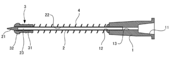
- the needle unit 10 includes a base portion 1 attached to the nozzle 203 of the syringe 20 and a needle member 2 attached to the distal end side of the base portion 1.
- the needle unit 10 further includes a slide member 3 attached to the needle member 2, a spring member 4 that biases the slide member 3 toward the distal end side of the needle member 2, and a cap 5 that covers the needle member 2. ing.
- each member will be described in detail.
- the base portion 1 is formed of hard plastic, glass, metal, or the like, and is formed in a cylindrical shape whose outer diameter becomes thinner toward the tip.
- the recessed part 11 in which the nozzle 203 of the syringe 20 is inserted is formed in the base end part side of the base part 1.
- an insertion port 12 into which the needle member 2 is inserted is formed at the distal end of the base portion 1, and the insertion port 12 communicates with the distal end of the recess 11 through the communication path 13.
- the fixing method is not specifically limited.
- luer lock type fixing in addition to fixing by simply press-fitting, so-called luer lock type fixing is also possible.
- a wall having a female screw is provided around the nozzle 203, and the nozzle 203 and the base portion 1 are fixed by screwing a male screw formed on the outer peripheral surface of the base portion 1 into the female screw.
- the needle member 2 is a known member that is also called a bud needle, and is formed of a hard metal, plastic, or the like. If it demonstrates in detail, this needle member 2 will have the front-end
- the internal space 22 opens on the base end side and communicates with the insertion port 12 of the base portion 1.
- a needle hole 23 is formed in the side surface near the distal end of the needle member 2 (base end side with respect to the conical portion), and the needle hole 23 communicates with the internal space 22.
- the concave portion 11 of the base portion 1, the communication path 13, the internal space 22 of the needle member 2, and the needle hole 23 communicate with each other, and the medicine flowing from the needle hole 23 passes through the base portion 1 and the syringe 20. It is possible to flow in.
- the needle hole 23 is preferably formed at a position 3 to 10 mm from the distal end of the needle member 2, that is, closer to the base portion 1 side than the inclined surface of the conical portion of the distal end portion 21.
- the needle hole 23 is formed on the inclined surface of the conical portion of the distal end portion 21, so that the closing by the slide member 3 is incomplete as will be described later. Because it becomes a thing. On the other hand, if it exceeds 10 mm, there is a risk of hindering the collection of the drug.
- the needle hole 23 is preferably formed in a circular or elliptical shape with a diameter of about 0.5 to 1.2 mm, for example.
- a plurality of needle holes 23 can also be provided. In this case, in addition to arranging the needle holes 23 side by side in the axial direction, they can be arranged on the opposite side with the axis of the needle member 2 interposed therebetween. However, if there are too many needle holes 23, it cannot be closed by the slide member 3, and should be at least a number that can be covered by the slide member 3.
- a cylindrical slide member 3 is attached to the needle member 2, and the slide member 3 is movable in the axial direction along the needle member 2.
- the slide member 3 includes a columnar main body 31 and a columnar engagement portion 32 that is attached to the distal end side of the main body 31 and has a diameter larger than that of the main body 31.
- the needle member 2 is inserted through a through hole that penetrates the engaging portion 32.
- a coiled spring member (biasing member) 4 is attached between the rear end portion of the slide member 3 and the front end portion of the base portion 1.
- the slide member 3 is biased toward the distal end side of the needle member 2 by the spring member 4.
- the slide member 3 It is arranged near the tip (first position) and covers the needle hole 23.
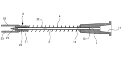
- the cap 5 is attached so as to cover the needle member 2
- the slide member 3 is pressed toward the base portion 1 by the cap 5, thereby compressing the spring member 4.
- the slide member 3 moves to the base part 1 side so as to expose the needle hole 23 (second position).
- the slide member 3 can employ a plastic such as thermoplastic elastomer, polyethylene, polypropylene, poly-4-methylpentene, polycarbonate, etc., but other resins having a low frictional force such as polytetrafluoroethylene and silicone resin can also be used. It can be used suitably. Further, if necessary, silicone coating, silicone coating, or the like can be performed. Moreover, it is preferable that the clearance gap between the inner wall surface of the through-hole of the slide member 3 and the side surface of the needle member 2 shall be larger than 0 mm and 50 micrometers or less, for example.
- the cap 5 is formed in a hollow cylindrical shape so as to cover the needle member 2, the front end side is closed, and the rear end side is opened. And the opening of a rear-end part is comprised so that the front-end
- the inner diameter of the small diameter portion 51 of the cap 5 is smaller than the outer diameter of the engaging portion 32 of the slide member 3, and the inner diameter of the large diameter portion 52 is larger than the outer diameter of the engaging portion 32. Therefore, as shown in FIG. 5, in a state where the cap 5 is attached to the base portion 1, the stepped portion 53 engages with the engaging portion 32 of the slide member 3 and presses it toward the base portion 1 side. It has become. That is, the slide member 3 moves from a position covering the needle hole 23 so that the needle hole 23 is exposed.
- the cap 5 can be formed of a general-purpose hard plastic such as polyethylene or polypropylene, and is preferably transparent or translucent so that the inside can be visually confirmed.
- a general-purpose hard plastic such as polyethylene or polypropylene
- the drug container 30 is generally called a vial, and is made of a glass bottle main body 301 and a bottle stopper (lid) that closes an opening formed in the upper portion of the bottle main body 301.
- the bottle body 301 is typically transparent or translucent.
- the bottle main body 301 is formed in a substantially cylindrical shape as a whole, and a neck portion 311 having a small diameter is formed on the upper portion thereof. Further, a flange portion 312 is formed above the neck portion 311, and the bottle stopper 302 is attached so as to cover the flange portion 312.
- the portion of the bottle stopper 302 that closes the upper opening of the bottle body 301 is made of an elastically deformable material such as rubber or elastomer, and can be pierced by the needle member 2 as will be described later. On the contrary, when the needle member 2 is pulled out from this portion, the needle hole formed by the piercing of the needle member 2 is closed almost instantly, though not completely, due to its elasticity. Further, the bottle cap 302 is wound and fixed to the flange portion 312 with an aluminum cap 303, and the aluminum cap 303 covers the entire portion except the central portion on the upper surface of the bottle cap 302. Therefore, when accessing the medicine container 30 using the syringe 20, the needle member 2 needs to be inserted into the bottle stopper 302 from the circular central portion on the upper surface thereof.
- an elastically deformable material such as rubber or elastomer
- the medicine accommodated in the medicine container 30 is not particularly limited, but for example, it is a medicine that can be a problem to be exposed to the outside.
- examples of such drugs are drugs that have cytotoxicity, and if exposed to them, those who handle them (mainly medical workers; hereinafter referred to as users) will have serious side effects or may be cytotoxic. It is a drug that may cause health damage or the like.
- examples of such drugs include antineoplastic agents, immunosuppressive agents, antiviral agents, antibiotics, radiopharmaceuticals and the like.
- Another example of a drug that can be a problem with exposure to the outside is a drug having odor or irritation.
- the medicine includes powder and the like.
- the liquid mixture is put into the medicine container 30 using the needle unit 10 and the syringe 20 before the suction.
- the drug is dissolved in the drug container 30 by the mixed solution.
- the mixed solution is physiological saline, Ringer's solution, distilled water, or the like, and is a solution for diluting or dissolving the drug.
- the base 1 of the needle unit 10 is fixed to the nozzle 203 of the syringe 20.
- the plunger 202 of the syringe 20 is in a state where it is pushed into the outer cylinder 201, that is, in a state where the gasket 204 is in close contact with the tip of the outer cylinder 201.
- the cap 5 is attached to the base portion 1, and the plunger 202 is moved backward to suck air into the outer cylinder 201.
- the cap 5 is removed from the base 1.
- the load that presses the slide member 3 toward the base portion 1 is released, so that the slide member 3 is urged toward the distal end side by the spring member 4 to cover the needle hole 23 as shown in FIG. Placed in position.
- the needle member 2 is inserted into the bottle stopper 302 of the medicine container 30, and the medicine is sucked while air is sent into the medicine container 30 by a pumping operation.
- the slide member 3 is pressed by the bottle stopper 302 and moves to the base portion 1 side. That is, since the slide member 3 can move along the needle member 2, it does not hinder the needle member 2 from being inserted into the bottle stopper 302.
- the needle member 2 is removed from the bottle stopper 302.
- the slide member 3 that has been pushed in by the bottle stopper 302 is released from being pressed by the bottle stopper 302, so that it is urged toward the distal end side by the spring member 4 to close the needle hole 23 as shown in FIG. 9.
- the slide member 3 immediately closes the needle hole 23, so that the sucked medicine can be prevented from leaking from the needle hole 23.
- the user inserts the needle member 2 into the bottle stopper of the mixed liquid container containing the mixed liquid and pushes the plunger 202.
- medical agent in the syringe 20 is inject
- medical agent is attracted
- the same thing may be used for the syringe 20 and you may change in the middle. Thereafter, the user carries the mixed liquid container containing the mixed chemical liquid to the patient and administers the mixed chemical liquid in the mixed liquid container to the patient by a method such as instillation.
- the slide member 3 that can move between the position for closing the needle hole 23 and the position for opening the needle hole 23 is provided along the needle member 2.
- the slide member 3 is biased by the spring member 4 so as to be disposed at a position where the needle hole 23 is closed.
- the slide member 3 is moved to a position where the needle hole is opened, and the internal space of the cap 5 communicates with the outside.
- the slide member 3 When the needle member 2 is inserted into the bottle stopper 302 of the medicine container 30, the slide member 3 is pressed toward the base portion 1 by the bottle stopper 302, so that the needle hole 23 is opened and the medicine can be sucked. Become. On the other hand, when the suction of the medicine is completed and the needle member 2 is pulled out from the bottle stopper 302, the pressing of the slide member 3 by the bottle stopper 302 is released, so that the slide member 3 is biased to the distal end side by the spring member 4. The needle hole 23 is immediately closed. Therefore, the aspirated medicine can be prevented from leaking from the needle hole 23.
- the step 53 is provided on the inner wall surface of the cap 5 in order to press the slide member 3 toward the base 1 when the cap 5 is attached to the base 1.
- the structure of may be sufficient.
- a protrusion (engaged part) is provided on the inner wall surface of the cap 5, the protrusion is engaged with the engagement part 32 of the slide member 3, and the slide member 3 is moved to the base part 1 side. it can.
- a pair of extending members 33 extending forward are attached to the distal end portion of the slide member 3.
- Each extending member 33 is formed in an arc shape in cross section, and the two extending members 33 surround the distal end portion 21 of the needle member 2 from the side surface. Thereby, when the slide member 3 closes the needle hole 23, the distal end portion 21 of the needle member 2 can be protected by the extending member 33.
- the front end surface of the internal space of the cap 5 presses both the extending members 33, thereby causing the slide member 3 to move to the base portion 1. Move to the side. As a result, the needle hole 23 is opened.
- the structure of the extending member 33 is not specifically limited, What is necessary is just a shape pressed by the front-end
- a gap is formed between the rear end portion of the cap 5 and the base portion 1 so that air can flow into the internal space of the cap 5, but air can flow into the internal space of the cap 5.
- Any other configuration may be used.
- a through-hole may be formed on the side surface of the cap 5 to allow air to flow in.
- the distal end portion 21 of the needle member 2 slightly protrudes from the distal end of the slide member 3 so that the position of the distal end portion 21 of the needle member 2 can be visually recognized.
- the position of the slide member 3 is adjusted so that the distal end portion 21 of the needle member 2 does not protrude from the slide member 3 so that the distal end portion 21 of the needle member 2 is accommodated in the slide member 3. You can also.
- the slide member 3 is formed of a transparent or translucent material, the position of the needle member 2 can be visually recognized even if the distal end portion 21 of the needle member 2 is covered with the slide member 3. .
- the configuration of the slide member 3 is not particularly limited, and is not particularly limited as long as it can move along the needle member 2 and can close the needle hole 23.
- the second position according to the present invention is not particularly limited as long as it is a position where the needle hole 23 is opened.
- the configuration of the base unit 1 is not particularly limited as long as it supports the needle member 2 and can be attached to the syringe 20.
- the biasing member of the present invention is not particularly limited as long as it can bias the slide member 3 from the position on the base portion 1 side to the position where the needle hole 23 is closed like the spring member of the above-described embodiment.
- a leaf spring can be used as the spring member.
- a pair of spring members 40 constituted by leaf springs are prepared, and the slide member 3 and the base portion 1 are connected by these. At this time, the two spring members 40 are disposed at symmetrical positions with the axis of the needle member 2 interposed therebetween.
- the cap 50 is not attached to the needle unit 10
- the two spring members 40 are in a state of extending almost straight without being curved.
- the cap 50 is formed so that the curved spring member 40 can be accommodated.
- the cap 50 according to this example also includes a small-diameter portion 510 that accommodates the distal end portion 21 of the needle member 2 and a large-diameter portion 520 closer to the base portion 1 than the above-described embodiment.
- the step part 530 is formed between these. Therefore, when the cap 50 is attached to the needle unit 10, the slide member 3 is pressed toward the base portion 1 by the step portion 530. At this time, each spring member 40 is curved so that the needle member 2 is separated, but the large-diameter portion 520 of the cap 50 is formed in a rectangular parallelepiped shape that can accommodate both curved spring members 40.
- the spring member 40 is constituted by the plate spring as described above, the following advantages are obtained. For example, if the spring member is coiled as in the above embodiment, when the needle member 2 as shown in FIG. 10 is pulled out from the state of being inserted into the bottle stopper 302 of the medicine container 30, the compressed spring member 4 There is a possibility that the slide member 3 jumps out of the tip of the needle member 2 due to the repulsion and comes off. On the other hand, when the spring member 40 is configured by a leaf spring as described above and the cap 50 is not attached to the needle unit 10, the slide member 3 is in the needle hole 23 at a position where the spring member 40 extends almost straight.
- the spring member 40 and the slide member 3 may be configured as separate members, or may be configured integrally with one material. Moreover, not only two such spring members 40 but also one or three or more can be provided.
- the slide member 3 and the base portion 1 can be connected by a deformable restricting member, for example, in the shape of the plate spring. If it does in this way, even if it uses the coil-shaped spring member 4, it can prevent that the slide member 3 detach
- plate spring will not be specifically limited if a spring function is exhibited with an elastic material with a restoring force, such as a metal and a plastic.
- Base part 2 Needle member 23: Needle hole 3: Slide member 33: Extension member 4: Spring member (biasing member) 40: Spring member (biasing member) 5: Cap 50: Cap 10: Needle unit 20: Syringe 51: Small diameter part 52: Large diameter part 53: Step part (engaged part) 510: Small diameter part 520: Large diameter part 530: Step part (engaged part)
Abstract
The present invention provides a needle unit mounted to a medical syringe. The needle unit is provided with: a needle member having a longitudinally extending inner space, the needle member also having a needle hole formed in the side surface of the front end of the needle member, the needle member further having an opening formed in the base end of the needle member, the inner space being in communication with the outside through the needle hole and the opening; a base section for supporting the base end of the needle member and providing communication between the syringe and the inner space of the needle member when mounted to the syringe; a slide member movable along the outer peripheral surface of the needle member and capable of having a first position where the slide member closes the needle hole and a second position where the slide member uncovers the needle hole at a position close to the base end than the first position; a pressing member for pressing the slide member from the second position side to the first position side; and a cap removably mounted to the base section so as to cover the needle member.
Description
本発明は、医療用のシリンジに装着される針ユニットに関する。
The present invention relates to a needle unit attached to a medical syringe.
従来より、癌化学療法等で用いられる、細胞毒性を有する薬剤を取り扱う医療従事者の健康被害が問題視されている。その理由は、通常、細胞毒性を有する薬剤は、薬剤容器内に封入された状態で流通するが、医療従事者は、シリンジにセットした針をこれらの容器の蓋部に刺通して、容器内の薬剤を溶解したり、希釈したり、混合したり、取り出したりしなければならない。そして、このような作業時、特に、針を蓋部から抜き取った後に、針穴に溜まっている薬剤が落下し、薬剤に曝露することが少なからず起きているからである。
Conventionally, the health hazards of medical workers who handle cytotoxic drugs used in cancer chemotherapy and the like have been regarded as a problem. The reason for this is that cytotoxic drugs usually circulate in a state of being enclosed in a drug container, but a medical worker inserts a needle set in a syringe into the lid of these containers, The drug must be dissolved, diluted, mixed and removed. This is because, during such work, in particular, after the needle has been removed from the lid, the drug accumulated in the needle hole has dropped and exposed to the drug.
その対策として、例えば、特許文献1には、針を薬剤容器の蓋部から抜き取る際に、針全体をカバーで覆い、針が外部に露出しないようにする装置が開示されている。
As a countermeasure, for example, Patent Document 1 discloses a device that covers the entire needle with a cover so that the needle is not exposed to the outside when the needle is removed from the lid of the drug container.
また、特許文献2には、血液が漏れることを防ぐべく、針の基台部に、針を覆う針カバーを取付けた採血用の注射器が開示されている。この針カバーは、針で血管を刺している間も針の基台部に取付けられたままとなる。すなわち、採血時には、針で針カバーを内側から突き刺して貫通させることにより、針を血管に挿入し、採血を行う。そして、採血の処理が終わり、針を血管から引き抜くと、針カバーの有する弾性により、自動的に針カバーが元の形状に復元し、再度針カバー内に収容される。また、この弾性により、針の通り抜けにより針カバーに形成された貫通孔も自動的に閉じられることになり、血液の飛散が防止される。この針カバーは、採血用途のみならず、細胞毒性や臭気性、刺激性を有する薬剤等の、外部に曝露することが問題となりうる薬剤をバイアル等の薬剤容器から抜き取る場合にも、利用することができる。
Patent Document 2 discloses a syringe for blood collection in which a needle cover that covers the needle is attached to the base of the needle in order to prevent blood from leaking. The needle cover remains attached to the base of the needle while the blood vessel is pierced with the needle. That is, at the time of blood collection, the needle cover is pierced from the inside with a needle and penetrated to insert the needle into the blood vessel and collect blood. When the blood collection process is completed and the needle is pulled out of the blood vessel, the needle cover is automatically restored to its original shape by the elasticity of the needle cover, and is again accommodated in the needle cover. Further, due to this elasticity, the through-hole formed in the needle cover is automatically closed when the needle passes through, and blood scattering is prevented. This needle cover should be used not only for blood collection, but also when extracting drugs that can be exposed to the outside, such as drugs with cytotoxicity, odor, or irritation, from drug containers such as vials. Can do.
さらに、特許文献3には、誤って針先に触れたり、針先で手指を指したりすることを防止するために、バネ等で付勢したカバーで針先を覆う針ユニットが開示されている。
Further, Patent Document 3 discloses a needle unit that covers the needle tip with a cover biased by a spring or the like in order to prevent the needle tip from being touched accidentally or pointing the finger with the needle tip. .
しかしながら、特許文献1の装置は、針全体を覆う部材が薬剤容器の蓋部に固定されるものであるので、適用できる薬剤容器が限定されるという問題がある。したがって、採取した薬剤を別の輸液容器などに注入する際には、その容器の口部に専用のアタッチメントを取付けるなどの対応が必要となる。また、装置の固定を解除するための取り外し操作も要するため、医療従事者にとっては手間がかかり、煩わしい。さらに、装置の構造が複雑であるため、装置全体が嵩張り、その上、コストが高くなるという問題もある。
However, the device of Patent Document 1 has a problem that applicable drug containers are limited because the member covering the entire needle is fixed to the lid of the drug container. Therefore, when the collected medicine is injected into another infusion container or the like, it is necessary to take a measure such as attaching a dedicated attachment to the mouth of the container. In addition, since a removal operation for releasing the fixation of the apparatus is required, it is troublesome and troublesome for the medical staff. Furthermore, since the structure of the apparatus is complicated, there is a problem that the entire apparatus is bulky and the cost is increased.
また、特許文献2のような針が針カバーで覆われているシリンジは、針カバーの弾性で元の形状に復元することにより針を再度覆うものであるが、針との摩擦力との兼ね合いで、復元に多少タイムラグが生じる虞があり、薬剤の漏えい防止効果は満足のいくものではない。
In addition, a syringe in which a needle is covered with a needle cover as in Patent Document 2 covers the needle again by restoring the original shape by the elasticity of the needle cover, but it balances with the frictional force with the needle. Therefore, there is a possibility that some time lag occurs in the restoration, and the effect of preventing the leakage of the drug is not satisfactory.
一方、特許文献3の針ユニットは、針先を覆うことにより誤って刺してしまうことは防がれるが、針穴に溜まっている薬剤の漏洩防止については何ら配慮がなされていない。
On the other hand, the needle unit of Patent Document 3 is prevented from being accidentally pierced by covering the needle tip, but no consideration is given to prevention of leakage of the drug accumulated in the needle hole.
本発明は、上記問題を解決するためになされたものであり、薬剤が針穴から外部に漏れることを防止することが可能な針ユニットを提供することを目的とする。
The present invention has been made to solve the above problems, and an object of the present invention is to provide a needle unit capable of preventing a medicine from leaking outside through a needle hole.
本発明は、医療用のシリンジに装着される針ユニットであって、長手方向に沿う内部空間を有する針部材であって、先端部の側面に形成された針穴、及び基端部に形成された開口を有し、前記内部空間は前記針穴及び開口を介して外部に連通する、針部材と、前記針部材の基端部を支持するとともに、前記シリンジに取付けられることで、前記シリンジと前記針部材の内部空間とを連通させる基台部と、前記針部材の外周面に沿って移動可能で、少なくとも、前記針穴を閉じる第1の位置と、前記第1の位置よりも前記基端部側において前記針穴を開放する第2の位置と、をとり得るスライド部材と、前記スライド部材を前記第2の位置側から第1の位置側へ付勢する付勢部材と、前記針部材を覆うように前記基台部に着脱可能に取付けられるキャップと、を備えている。
The present invention is a needle unit to be attached to a medical syringe, and is a needle member having an internal space along the longitudinal direction, which is formed in a needle hole formed in a side surface of a distal end portion and a proximal end portion. A needle member that communicates with the outside through the needle hole and the opening, and supports the proximal end of the needle member and is attached to the syringe, A base portion that communicates with the internal space of the needle member; a base portion that is movable along an outer peripheral surface of the needle member; and at least a first position that closes the needle hole; and the base position that is more than the first position. A slide member that can take a second position for opening the needle hole on the end side, a biasing member that biases the slide member from the second position side to the first position side, and the needle Removably attached to the base so as to cover the member Is provided with a cap that, the.
この構成によれば、針部材に沿って、針穴を塞ぐ第1の位置と針穴を開放する第2の位置との間を移動可能なスライド部材を備えており、このスライド部材は、キャップが取付けられていないときには、第1の位置に配置されるように付勢部材によって付勢されている。
According to this configuration, the slide member that can move between the first position for closing the needle hole and the second position for opening the needle hole is provided along the needle member. When is not attached, it is urged by the urging member so as to be arranged at the first position.
そして、薬剤容器の蓋部に針部材を刺し込んだときには、蓋部によってスライド部材が第2の位置側に押圧されるため、針穴が開放され、薬剤が吸引可能となる。一方、薬剤の吸引が完了し、針部材を蓋部から引き抜いたときには、蓋部によるスライド部材の押圧が解除されるため、スライド部材は、付勢部材によって第1の位置に付勢され、針穴を即座に塞ぐ。そのため、吸引された薬剤が針穴から漏出するのを防止することができる。
When the needle member is inserted into the lid portion of the medicine container, the slide member is pressed toward the second position by the lid portion, so that the needle hole is opened and the medicine can be sucked. On the other hand, when the suction of the medicine is completed and the needle member is pulled out from the lid portion, the pressing of the slide member by the lid portion is released, so the slide member is biased to the first position by the biasing member, and the needle Immediately plug the hole. Therefore, it is possible to prevent the sucked medicine from leaking from the needle hole.
上記針ユニットにおいては、前記キャップが前記基台部に取付けられているときに、前記スライド部材を前記第2の位置へ移動させるとともに当該キャップの内部空間と外部とが連通するように構成することができる。
The needle unit is configured such that when the cap is attached to the base portion, the slide member is moved to the second position and the internal space of the cap communicates with the outside. Can do.
この構成により、次の効果を得ることができる。まず、シリンジで薬剤容器から薬剤を抜き取っていくと、薬剤容器の内圧は徐々に低下していくことになるが、ある一定以下の負圧になると、薬剤を抜き取ることが困難になる。そこで、薬剤を抜き取る際には、薬剤容器内の圧力を低下させ過ぎないように、シリンジから薬剤容器内へ、抜き取る薬剤と同量程度の空気を注入する。そのために、先にシリンジの内部空間にその分の空気を取り入れるという操作が行われる。そして、この操作は、安全性や衛生性を保つため、注射針をシリンジに装着し、薬剤容器に針を差し込む前に、針にキャップを被せたままの状態でしばしば行われる。
This configuration can provide the following effects. First, when the drug is extracted from the drug container with a syringe, the internal pressure of the drug container gradually decreases. However, when the negative pressure is below a certain level, it is difficult to extract the drug. Therefore, when extracting the drug, air of the same amount as the drug to be extracted is injected from the syringe into the drug container so as not to reduce the pressure in the drug container excessively. For this purpose, an operation is performed in which the air is first taken into the internal space of the syringe. In order to maintain safety and hygiene, this operation is often performed in a state where the needle is attached to the syringe and the needle is covered with the cap before the needle is inserted into the drug container.
しかしながら、特許文献2のような針が針カバーで覆われているシリンジの場合、薬剤容器内に針を挿入する前においては、針が針カバーに収容されているため、予めシリンジの内部空間に空気を取り込んでおくことが容易ではない。なぜならば、針カバー内の空気がシリンジの内部空間に吸入されてしまうと、針カバーが収縮してしまい、それ以上の空気の吸引が困難となるからである。
However, in the case of a syringe in which the needle is covered with a needle cover as in Patent Document 2, the needle is accommodated in the needle cover before the needle is inserted into the drug container. It is not easy to take in air. This is because if the air in the needle cover is sucked into the internal space of the syringe, the needle cover contracts and it becomes difficult to suck more air.
そこで、上記のように構成すると、キャップが取付けられているときに、スライド部材が第2の位置へ移動するため、キャップの外部、キャップの内部空間、及び針穴が連通する。その結果、針ユニットが取付けられたシリンジに空気を吸引することが可能となる。そのため、薬剤容器から薬剤を吸引する際に、薬剤容器内に空気を注入し、薬剤容器内の圧力が低下するのを防止することができる。
Therefore, when configured as described above, the slide member moves to the second position when the cap is attached, so that the outside of the cap, the internal space of the cap, and the needle hole communicate with each other. As a result, air can be sucked into the syringe to which the needle unit is attached. Therefore, when a medicine is sucked from the medicine container, air can be injected into the medicine container to prevent the pressure in the medicine container from decreasing.
上記針ユニットにおいて、付勢部材は種々の態様で構成することができる。例えば、前記付勢部材は、前記基台部と前記スライド部材とを連結し、前記針部材の外周面に沿って延びるコイル状のバネによって構成することができる。
In the needle unit, the biasing member can be configured in various ways. For example, the urging member can be configured by a coiled spring that connects the base portion and the slide member and extends along the outer peripheral surface of the needle member.
あるいは、前記付勢部材は、前記基台部と前記スライド部材とを連結する、少なくとも1つの板バネによって構成することができる。
Alternatively, the urging member can be constituted by at least one leaf spring that connects the base portion and the slide member.
特に、一対の前記板バネを備えたときには、当該一対の板バネを、前記針部材の軸線を挟んで対象となる位置に配置することができる。
In particular, when a pair of leaf springs are provided, the pair of leaf springs can be arranged at a target position with the axis of the needle member interposed therebetween.
上記各針ユニットにおいて、前記スライド部材は、前記付勢部材に負荷が作用していない状態で、前記針部材の先端を覆うように構成することができる。
In each of the needle units, the slide member can be configured to cover the tip of the needle member in a state where no load is applied to the biasing member.
このとき、前記スライド部材を、透明または半透明の材料により形成することができる。これにより、スライド部材が針部材の先端を覆っていても、針部材の先端をスライド部材の外部から視認することができる。
At this time, the slide member can be formed of a transparent or translucent material. Thereby, even if the slide member covers the tip of the needle member, the tip of the needle member can be visually recognized from the outside of the slide member.
上記針ユニットにおいて、スライド部材を第2の位置側に移動させるためには、キャップは種々の構成を取ることができるが、例えば、前記キャップの内部空間に、前記キャップが前記基台部に取付けられたときに、前記スライド部材と係合し、当該スライド部材を前記第2の位置へと移動させる係合部を備えることができる。
In the needle unit, in order to move the slide member to the second position side, the cap can take various configurations. For example, the cap is attached to the base portion in the internal space of the cap. And an engaging portion that engages with the slide member and moves the slide member to the second position.
係合部の構成として、例えば、前記内部空間が、前記針部材の先端側に配置される小径部と、当該小径部と連続し前記基端部側に配置される大径部とを備えるようにし、前記小径部と大径部との間の段部が、前記係合部を構成するようにすることができる。
As a configuration of the engaging portion, for example, the internal space includes a small-diameter portion disposed on the distal end side of the needle member, and a large-diameter portion that is continuous with the small-diameter portion and disposed on the proximal end portion side. In addition, the step portion between the small diameter portion and the large diameter portion may constitute the engagement portion.
また、スライド部材を第2の位置側に移動させるため、次のように構成することができる。すなわち、前記スライド部材が、当該スライド部材が前記第1の位置にあるときに、前記針部材の先端部の側面を覆う延設部材を備え、当該延設部材を、前記キャップが前記基台部に取付けられているときに、当該キャップにより前記基端部側に押圧されるように構成することができる。
Further, since the slide member is moved to the second position side, it can be configured as follows. That is, the slide member includes an extension member that covers a side surface of the distal end portion of the needle member when the slide member is in the first position, and the cap is provided on the base portion. When it is attached to, it can comprise so that it may press on the said base end part side with the said cap.
上記各針ユニットにおいては、前記スライド部材と前記針部材の側面との距離を、0より大きく、50μm以下とすることができる。これは、スライド部材と前記針部材の側面との距離が0となると、摩擦力によってスライド部材が針部材に沿って即座に移動しがたくなるからであり、50μmより大きいと、薬剤が漏出するおそれがあることによる。
In each of the needle units, the distance between the slide member and the side surface of the needle member can be greater than 0 and 50 μm or less. This is because when the distance between the slide member and the side surface of the needle member becomes 0, the slide member is difficult to move immediately along the needle member due to frictional force. When the distance is larger than 50 μm, the drug leaks out. Because there is a fear.
また、上記各針ユニットにおいて、前記針穴は、前記針部材の先端から3~10mmの位置に形成することができる。これは、針穴がこれよりも針部材の先端側に位置すると、針部材の鋭利な先端部の円錐部分の傾斜面に、針穴が形成されることになるため、スライド部材による閉鎖が不完全なものとなるからである。一方、10mmを越えると、薬剤の採取に支障を来すおそれがあることによる。
In each of the needle units, the needle hole can be formed at a position 3 to 10 mm from the tip of the needle member. This is because if the needle hole is positioned closer to the tip end side of the needle member than this, the needle hole is formed on the inclined surface of the conical portion of the sharp tip portion of the needle member, so that the slide member cannot be closed. Because it will be perfect. On the other hand, if it exceeds 10 mm, it may interfere with drug collection.
本発明に係る針ユニットによれば、薬剤が針穴から外部に漏れることを防止しつつ、針をシリンジ内に装着しさらにキャップを被せた状態で、シリンジの内部空間へ空気を吸引することができる。
According to the needle unit according to the present invention, it is possible to suck air into the internal space of the syringe while preventing the medicine from leaking from the needle hole and attaching the needle into the syringe and covering the syringe. it can.
以下、本発明に係る針ユニットの一実施形態について、図面を参照しつつ説明する。本実施形態に係る針ユニット10は、医療用のシリンジ20に取付けられるものである。以下では、まず医療用シリンジ20について説明した後、針ユニット10について説明し、その後、針ユニット10の使用方法について説明する。
Hereinafter, an embodiment of a needle unit according to the present invention will be described with reference to the drawings. The needle unit 10 according to this embodiment is attached to a medical syringe 20. Below, after explaining the medical syringe 20 first, the needle unit 10 will be explained, and then the method of using the needle unit 10 will be explained.
<1.シリンジ>
図1は、本実施形態に係るシリンジ20の一例である。このシリンジ20は、公知のものであり、中空の筒状の外筒201と、この外筒201の後端の開口から挿入されるプランジャ202と、を備えている。外筒201の先端には、小径のノズル203が取り付けられており、このノズル203に、針ユニット10が取り付けられる。また、外筒201に挿入されるプランジャ202の先端には、ガスケット204が取り付けられており、このガスケット204により外筒201の内部空間の後端を密閉する。 <1. Syringe>
FIG. 1 is an example of asyringe 20 according to the present embodiment. The syringe 20 is a known one, and includes a hollow cylindrical outer cylinder 201 and a plunger 202 inserted from an opening at the rear end of the outer cylinder 201. A small diameter nozzle 203 is attached to the tip of the outer cylinder 201, and the needle unit 10 is attached to the nozzle 203. A gasket 204 is attached to the tip of the plunger 202 inserted into the outer cylinder 201, and the rear end of the inner space of the outer cylinder 201 is sealed by this gasket 204.
図1は、本実施形態に係るシリンジ20の一例である。このシリンジ20は、公知のものであり、中空の筒状の外筒201と、この外筒201の後端の開口から挿入されるプランジャ202と、を備えている。外筒201の先端には、小径のノズル203が取り付けられており、このノズル203に、針ユニット10が取り付けられる。また、外筒201に挿入されるプランジャ202の先端には、ガスケット204が取り付けられており、このガスケット204により外筒201の内部空間の後端を密閉する。 <1. Syringe>
FIG. 1 is an example of a
<2.針ユニット>
次に、針ユニットについて説明する。図2はキャップが取り付けられた状態を示す針ユニットの斜視図、図3はキャップが取り外された状態を示す針ユニットの斜視図、図4は図3における針ユニットの断面図、図5は図2の断面図である。なお、以下では、説明の便宜のため、図5に示す針部材の延びる方向を軸方向と称する。また、図4の左側を先端側または前側、右側を基端側または後端側と称することとし、この向きを基準に他の図面も説明する。但し、この向きによって、本発明が限定されるものではない。 <2. Needle unit>
Next, the needle unit will be described. 2 is a perspective view of the needle unit with the cap attached, FIG. 3 is a perspective view of the needle unit with the cap removed, FIG. 4 is a cross-sectional view of the needle unit in FIG. 3, and FIG. FIG. In the following, for convenience of explanation, the extending direction of the needle member shown in FIG. 5 is referred to as the axial direction. Further, the left side of FIG. 4 is referred to as the front end side or the front side, and the right side is referred to as the base end side or the rear end side, and other drawings will be described based on this orientation. However, the present invention is not limited by this orientation.
図2~図5に示すように、この針ユニット10は、シリンジ20のノズル203に取付けられる基台部1と、この基台部1の先端側に取付けられる針部材2とを備えている。さらに、この針ユニット10は、針部材2に取り付けられるスライド部材3と、このスライド部材3を針部材2の先端側に付勢するバネ部材4と、針部材2を覆うキャップ5と、を備えている。以下、各部材について詳細に説明する。
2 to 5, the needle unit 10 includes a base portion 1 attached to the nozzle 203 of the syringe 20 and a needle member 2 attached to the distal end side of the base portion 1. The needle unit 10 further includes a slide member 3 attached to the needle member 2, a spring member 4 that biases the slide member 3 toward the distal end side of the needle member 2, and a cap 5 that covers the needle member 2. ing. Hereinafter, each member will be described in detail.
基台部1は、硬質のプラスチック、ガラス、または金属等で形成されており、先端にいくにしたがって外径が細くなる筒状に形成されている。そして、基台部1の基端部側にはシリンジ20のノズル203が挿入される凹部11が形成されている。一方、基台部1の先端には針部材2が挿入される挿入口12が形成されており、この挿入口12と凹部11の先端とが連通路13によって連通している。なお、シリンジ20のノズル203と基台部1とは、ノズル203を凹部11に挿入することで固定されるが、その固定方法は、特には限定されない。例えば、単に圧入により固定するほか、いわゆるルアーロック式の固定も可能である。ルアーロック式では、ノズル203の周囲に雌ネジを有する壁を設け、基台部1の外周面に形成された雄ネジを雌ネジにねじ込むことでノズル203と基台部1とを固定する。
The base portion 1 is formed of hard plastic, glass, metal, or the like, and is formed in a cylindrical shape whose outer diameter becomes thinner toward the tip. And the recessed part 11 in which the nozzle 203 of the syringe 20 is inserted is formed in the base end part side of the base part 1. As shown in FIG. On the other hand, an insertion port 12 into which the needle member 2 is inserted is formed at the distal end of the base portion 1, and the insertion port 12 communicates with the distal end of the recess 11 through the communication path 13. In addition, although the nozzle 203 and the base part 1 of the syringe 20 are fixed by inserting the nozzle 203 in the recessed part 11, the fixing method is not specifically limited. For example, in addition to fixing by simply press-fitting, so-called luer lock type fixing is also possible. In the luer lock type, a wall having a female screw is provided around the nozzle 203, and the nozzle 203 and the base portion 1 are fixed by screwing a male screw formed on the outer peripheral surface of the base portion 1 into the female screw.
次に、針部材2について説明する。本実施形態に係る針部材2は、つぼみ針とも称される公知のものであり、硬質の金属、プラスチックなどで形成されている。より詳細に説明すると、この針部材2は、先端部21が鋭利な円錐状に形成されるとともに、長手方向に延びる内部空間22を有している。そして、この内部空間22は基端部側で開口し、基台部1の挿入口12に通じている。また、針部材2の先端付近(円錐部分よりも基端側)の側面には、針穴23が形成されており、この針穴23は内部空間22に連通している。したがって、基台部1の凹部11、連通路13、針部材2の内部空間22、及び針穴23は連通しており、針穴23から流入した薬剤は、基台部1を介してシリンジ20内に流入可能となっている。
Next, the needle member 2 will be described. The needle member 2 according to this embodiment is a known member that is also called a bud needle, and is formed of a hard metal, plastic, or the like. If it demonstrates in detail, this needle member 2 will have the front-end | tip part 21 in the shape of a sharp cone, and has the internal space 22 extended in a longitudinal direction. The internal space 22 opens on the base end side and communicates with the insertion port 12 of the base portion 1. Further, a needle hole 23 is formed in the side surface near the distal end of the needle member 2 (base end side with respect to the conical portion), and the needle hole 23 communicates with the internal space 22. Therefore, the concave portion 11 of the base portion 1, the communication path 13, the internal space 22 of the needle member 2, and the needle hole 23 communicate with each other, and the medicine flowing from the needle hole 23 passes through the base portion 1 and the syringe 20. It is possible to flow in.
なお、針穴23は、針部材2の先端から3~10mmの位置、即ち、先端部21の円錐部分の傾斜面よりも基台部1側に形成されることが好ましい。針穴23がこれよりも先端側に位置すると、針穴23は、先端部21の円錐部分の傾斜面に形成されることになるため、後述するように、スライド部材3により閉鎖が不完全なものとなるからである。一方、10mmを越えると、薬剤の採取に支障を来すおそれがある。また、針穴23は、針部材2の外径にもよるが、例えば、直径が0.5~1.2mm程度の円形または楕円形状に形成することが好ましい。また、針穴23は、複数個設けることもできる。この場合は、針穴23を軸方向に並べて配置するほか、針部材2の軸心を挟んで反対側に配置することもできる。但し、針穴23が多すぎると、スライド部材3によって閉鎖できなくなるため、少なくともスライド部材3によって覆うことができる数にすべきである。
The needle hole 23 is preferably formed at a position 3 to 10 mm from the distal end of the needle member 2, that is, closer to the base portion 1 side than the inclined surface of the conical portion of the distal end portion 21. When the needle hole 23 is located on the distal end side from this, the needle hole 23 is formed on the inclined surface of the conical portion of the distal end portion 21, so that the closing by the slide member 3 is incomplete as will be described later. Because it becomes a thing. On the other hand, if it exceeds 10 mm, there is a risk of hindering the collection of the drug. Further, although depending on the outer diameter of the needle member 2, the needle hole 23 is preferably formed in a circular or elliptical shape with a diameter of about 0.5 to 1.2 mm, for example. A plurality of needle holes 23 can also be provided. In this case, in addition to arranging the needle holes 23 side by side in the axial direction, they can be arranged on the opposite side with the axis of the needle member 2 interposed therebetween. However, if there are too many needle holes 23, it cannot be closed by the slide member 3, and should be at least a number that can be covered by the slide member 3.
また、針部材2には、筒状のスライド部材3が取り付けられており、スライド部材3は、針部材2に沿って軸方向に移動可能となっている。このスライド部材3は、円柱状の本体部31と、この本体部31の先端側に取り付けられ、本体部31よりも径の大きい円柱状の係合部32とを備えており、これら本体部31と係合部32とを貫通する貫通孔に、針部材2が挿通されている。また、スライド部材3の後端部と基台部1の先端部との間には、コイル状のバネ部材(付勢部材)4が取り付けられている。すなわち、このバネ部材4には針部材2が挿通され、バネ部材4の先端部がスライド部材3の後端部に固定されるとともに、バネ部材4の後端部が基台部1の先端部に固定されている。このバネ部材4により、図4に示すように、スライド部材3は、針部材2の先端側に付勢されており、バネ部材4が非圧縮状態のとき、スライド部材3は、針部材2の先端付近に配置され(第1の位置)、針穴23を覆うようになっている。そして、後述するように、針部材2を覆うようにキャップ5を取り付けると、スライド部材3は、キャップ5によって基台部1側に押圧され、これによってバネ部材4が圧縮される。その結果、スライド部材3は針穴23を露出するように、基台部1側に移動する(第2の位置)。
Further, a cylindrical slide member 3 is attached to the needle member 2, and the slide member 3 is movable in the axial direction along the needle member 2. The slide member 3 includes a columnar main body 31 and a columnar engagement portion 32 that is attached to the distal end side of the main body 31 and has a diameter larger than that of the main body 31. The needle member 2 is inserted through a through hole that penetrates the engaging portion 32. A coiled spring member (biasing member) 4 is attached between the rear end portion of the slide member 3 and the front end portion of the base portion 1. That is, the needle member 2 is inserted into the spring member 4, the distal end portion of the spring member 4 is fixed to the rear end portion of the slide member 3, and the rear end portion of the spring member 4 is the distal end portion of the base portion 1. It is fixed to. As shown in FIG. 4, the slide member 3 is biased toward the distal end side of the needle member 2 by the spring member 4. When the spring member 4 is in an uncompressed state, the slide member 3 It is arranged near the tip (first position) and covers the needle hole 23. As will be described later, when the cap 5 is attached so as to cover the needle member 2, the slide member 3 is pressed toward the base portion 1 by the cap 5, thereby compressing the spring member 4. As a result, the slide member 3 moves to the base part 1 side so as to expose the needle hole 23 (second position).
なお、スライド部材3は、熱可塑性エラストマー、ポリエチレン、ポリプロピレン、ポリ4-メチルペンテン、ポリカーボネート等のようなプラスチック等を採用できるが、その他、ポリテトラフルオロエチレンやシリコーン樹脂等の摩擦力の少ない樹脂も好適に用いることができる。また、必要に応じて、シリコーンのコーティングやシリコーンの塗布等を行うこともできる。また、スライド部材3の貫通孔の内壁面と針部材2の側面との隙間は、例えば、0mmより大きく、50μm以下とすることが好ましい。これは、両者の間に隙間がないと、スライド部材3が針部材2に沿って瞬時に移動しがたくなるからであり、50μmよりも大きいと、後述するように、スライド部材3が針穴23を覆っていても、針穴23から薬剤が漏れる可能性があることによる。
The slide member 3 can employ a plastic such as thermoplastic elastomer, polyethylene, polypropylene, poly-4-methylpentene, polycarbonate, etc., but other resins having a low frictional force such as polytetrafluoroethylene and silicone resin can also be used. It can be used suitably. Further, if necessary, silicone coating, silicone coating, or the like can be performed. Moreover, it is preferable that the clearance gap between the inner wall surface of the through-hole of the slide member 3 and the side surface of the needle member 2 shall be larger than 0 mm and 50 micrometers or less, for example. This is because if there is no gap between the two, the slide member 3 is difficult to move instantaneously along the needle member 2, and if it is larger than 50 μm, the slide member 3 will move into the needle hole as will be described later. This is because the medicine may leak from the needle hole 23 even if the cover 23 is covered.
次に、キャップ5について説明する。キャップ5は、針部材2を覆うように、中空の筒状に形成されており、先端側が閉じ、後端側が開放されている。そして、後端部の開口が、基台部1の先端部に嵌まるように構成されている。また、キャップ5の内壁面において、軸方向の先端部付近には、径の小さい小径部51が形成されており、小径部51よりも後端側には径が大きい大径部52が形成されている。そのため、キャップ5の小径部51と大径部52との間には、段部53が形成されており、この段部53がスライド部材3の係合部32と係合可能となっている。すなわち、キャップ5の小径部51の内径は、スライド部材3の係合部32の外径よりも小さく、大径部52の内径は、係合部32の外径よりも大きい。そのため、図5に示すように、キャップ5が基台部1に取り付けられた状態では、段部53がスライド部材3の係合部32に係合し、基台部1側へ押圧するようになっている。すなわち、スライド部材3は、針穴23を覆う位置から移動し、針穴23が露出するようになっている。
Next, the cap 5 will be described. The cap 5 is formed in a hollow cylindrical shape so as to cover the needle member 2, the front end side is closed, and the rear end side is opened. And the opening of a rear-end part is comprised so that the front-end | tip part of the base part 1 may be fitted. Further, on the inner wall surface of the cap 5, a small-diameter portion 51 having a small diameter is formed near the tip portion in the axial direction, and a large-diameter portion 52 having a large diameter is formed on the rear end side of the small-diameter portion 51. ing. Therefore, a step portion 53 is formed between the small diameter portion 51 and the large diameter portion 52 of the cap 5, and the step portion 53 can be engaged with the engagement portion 32 of the slide member 3. That is, the inner diameter of the small diameter portion 51 of the cap 5 is smaller than the outer diameter of the engaging portion 32 of the slide member 3, and the inner diameter of the large diameter portion 52 is larger than the outer diameter of the engaging portion 32. Therefore, as shown in FIG. 5, in a state where the cap 5 is attached to the base portion 1, the stepped portion 53 engages with the engaging portion 32 of the slide member 3 and presses it toward the base portion 1 side. It has become. That is, the slide member 3 moves from a position covering the needle hole 23 so that the needle hole 23 is exposed.
さらに、キャップ5が基台部1に取付けられたとき、キャップ5の後端部と、基台部1との間には、わずかな隙間(図示省略)が形成されるようになっており、これにより、キャップ5の内部空間と外部とが連通するようになっている。
Furthermore, when the cap 5 is attached to the base portion 1, a slight gap (not shown) is formed between the rear end portion of the cap 5 and the base portion 1. As a result, the internal space of the cap 5 communicates with the outside.
なお、キャップ5は、例えば、ポリエチレン、ポリプロピレン等の汎用の硬質プラスチックにより形成することができ、内部を視認できるように、透明または半透明であることが好ましい。
The cap 5 can be formed of a general-purpose hard plastic such as polyethylene or polypropylene, and is preferably transparent or translucent so that the inside can be visually confirmed.
<3.針ユニットの使用方法>
ここでは、薬剤容器30に収容されている薬剤をシリンジ20に取り付けた針ユニット10により採取する方法について説明する。まず、使用方法の説明に先立って、ここで使用される薬剤容器の一例を説明する。 <3. How to use the needle unit>
Here, a method of collecting the medicine stored in themedicine container 30 by the needle unit 10 attached to the syringe 20 will be described. First, an example of a medicine container used here will be described prior to the description of the usage method.
ここでは、薬剤容器30に収容されている薬剤をシリンジ20に取り付けた針ユニット10により採取する方法について説明する。まず、使用方法の説明に先立って、ここで使用される薬剤容器の一例を説明する。 <3. How to use the needle unit>
Here, a method of collecting the medicine stored in the
図6に示すように、この薬剤容器30は、一般にバイアル瓶と呼ばれるものであり、ガラス製のボトル本体301と、このボトル本体301の上部に形成された開口を閉鎖するボトル栓(蓋部)302とを有する。ボトル本体301は、典型的には、透明又は半透明である。ボトル本体301は、全体として略円柱形状に形成されており、その上部には径が小さいネック部311が形成されている。さらに、ネック部311の上方には、フランジ部312が形成されており、このフランジ部312を覆うように、ボトル栓302が取り付けられる。
As shown in FIG. 6, the drug container 30 is generally called a vial, and is made of a glass bottle main body 301 and a bottle stopper (lid) that closes an opening formed in the upper portion of the bottle main body 301. 302. The bottle body 301 is typically transparent or translucent. The bottle main body 301 is formed in a substantially cylindrical shape as a whole, and a neck portion 311 having a small diameter is formed on the upper portion thereof. Further, a flange portion 312 is formed above the neck portion 311, and the bottle stopper 302 is attached so as to cover the flange portion 312.
ボトル栓302において、ボトル本体301の上部開口を塞ぐ部分は、ゴム、エラストマー等の弾性変形可能な材料により形成されており、後述するように、針部材2により刺通可能である。逆に、この部分から針部材2を引き抜くと、針部材2の刺し込みにより形成された針穴は、その弾性により、完全ではないものの殆ど瞬時に閉じられる。また、ボトル栓302は、フランジ部312に対しアルミキャップ303で巻き閉め固定されており、このアルミキャップ303は、ボトル栓302の上面の中央部分を除く部分全体を覆っている。したがって、シリンジ20を用いて薬剤容器30内にアクセスする場合には、針部材2をボトル栓302に対しその上面の円形状の中央部分から刺し込む必要がある。
The portion of the bottle stopper 302 that closes the upper opening of the bottle body 301 is made of an elastically deformable material such as rubber or elastomer, and can be pierced by the needle member 2 as will be described later. On the contrary, when the needle member 2 is pulled out from this portion, the needle hole formed by the piercing of the needle member 2 is closed almost instantly, though not completely, due to its elasticity. Further, the bottle cap 302 is wound and fixed to the flange portion 312 with an aluminum cap 303, and the aluminum cap 303 covers the entire portion except the central portion on the upper surface of the bottle cap 302. Therefore, when accessing the medicine container 30 using the syringe 20, the needle member 2 needs to be inserted into the bottle stopper 302 from the circular central portion on the upper surface thereof.
また、この薬剤容器30に収容されている薬剤は、特には限定されないが、例えば、外部に曝露することが問題となり得る薬剤である。そのような薬剤としては、例えば、細胞毒性を有する薬剤であり、曝露すると、これを取り扱う者(主として、医療従事者。以下、ユーザーと言う。)に重篤な副作用を及ぼしたり、細胞毒性に由来する健康被害を及ぼしたり等する可能性のある薬剤である。このような薬剤の例としては、抗悪性腫瘍剤、免疫抑制剤、抗ウィルス剤、抗生物質、放射性医薬品等が挙げられる。また、外部に曝露することが問題となり得る薬剤の別の例としては、臭気性や刺激性を有する薬剤などが挙げられる。なお、薬剤としては、液体のほか、粉末状のもの等があるが、粉末状の薬剤を吸引する際には、吸引に先立ち、針ユニット10及びシリンジ20を用いて薬剤容器30内に混合液を注入し、薬剤容器30内で薬剤を混合液により溶解させる。混合液は、生理食塩水やリンゲル液、蒸留水等であり、薬剤を希釈したり、溶解させたりするための溶液である。
Further, the medicine accommodated in the medicine container 30 is not particularly limited, but for example, it is a medicine that can be a problem to be exposed to the outside. Examples of such drugs are drugs that have cytotoxicity, and if exposed to them, those who handle them (mainly medical workers; hereinafter referred to as users) will have serious side effects or may be cytotoxic. It is a drug that may cause health damage or the like. Examples of such drugs include antineoplastic agents, immunosuppressive agents, antiviral agents, antibiotics, radiopharmaceuticals and the like. Another example of a drug that can be a problem with exposure to the outside is a drug having odor or irritation. In addition to the liquid, the medicine includes powder and the like. When the powdered medicine is sucked, the liquid mixture is put into the medicine container 30 using the needle unit 10 and the syringe 20 before the suction. And the drug is dissolved in the drug container 30 by the mixed solution. The mixed solution is physiological saline, Ringer's solution, distilled water, or the like, and is a solution for diluting or dissolving the drug.
続いて、上記針ユニット10の使用方法について説明する。まず、図7に示すように、針ユニット10の基台部1を、シリンジ20のノズル203に固定する。このとき、シリンジ20のプランジャ202は、外筒201に押し込まれた状態、つまりガスケット204が外筒201の先端部に密着した状態としておく。続いて、図8に示すように、キャップ5を基台部1に取り付けるとともに、プランジャ202を後方に移動させ、外筒201内に空気を吸引する。このとき、キャップ5の基端部の開口と基台部1との間には隙間が形成され、且つ、スライド部材3は針穴23を開放する第2の位置にあり、針穴23が露出しているため、プランジャ202を後方に移動させると、上述した隙間や針穴23から流入する空気が外筒201内に吸引される。
Subsequently, a method of using the needle unit 10 will be described. First, as shown in FIG. 7, the base 1 of the needle unit 10 is fixed to the nozzle 203 of the syringe 20. At this time, the plunger 202 of the syringe 20 is in a state where it is pushed into the outer cylinder 201, that is, in a state where the gasket 204 is in close contact with the tip of the outer cylinder 201. Subsequently, as shown in FIG. 8, the cap 5 is attached to the base portion 1, and the plunger 202 is moved backward to suck air into the outer cylinder 201. At this time, a gap is formed between the opening of the base end portion of the cap 5 and the base portion 1, and the slide member 3 is in a second position where the needle hole 23 is opened, and the needle hole 23 is exposed. Therefore, when the plunger 202 is moved backward, the air flowing in from the gaps and the needle holes 23 is sucked into the outer cylinder 201.
次に、キャップ5を基台部1から取り外す。これにより、スライド部材3を基台部1側へ押圧する負荷が解除されるため、図9に示すように、スライド部材3は、バネ部材4によって先端側へ付勢され、針穴23を覆う位置に配置される。この状態で、針部材2を薬剤容器30のボトル栓302に刺し込み、ポンピング操作により、薬剤容器30内に空気を送り込みながら、薬剤を吸引する。このとき、図10に示すように、針部材2をボトル栓302に刺し込むと、スライド部材3は、ボトル栓302によって押圧され、基台部1側へ移動する。すなわち、スライド部材3は針部材2に沿って移動可能であるため、針部材2のボトル栓302への刺し込みの障害にはならない。
Next, the cap 5 is removed from the base 1. As a result, the load that presses the slide member 3 toward the base portion 1 is released, so that the slide member 3 is urged toward the distal end side by the spring member 4 to cover the needle hole 23 as shown in FIG. Placed in position. In this state, the needle member 2 is inserted into the bottle stopper 302 of the medicine container 30, and the medicine is sucked while air is sent into the medicine container 30 by a pumping operation. At this time, as shown in FIG. 10, when the needle member 2 is inserted into the bottle stopper 302, the slide member 3 is pressed by the bottle stopper 302 and moves to the base portion 1 side. That is, since the slide member 3 can move along the needle member 2, it does not hinder the needle member 2 from being inserted into the bottle stopper 302.
そして、所定量の薬剤がシリンジ20の外筒201内に採取されると、針部材2をボトル栓302から抜き取る。このとき、ボトル栓302によって押し込まれていたスライド部材3は、ボトル栓302による押圧が解除されるため、図9に示すように、バネ部材4によって先端側へ付勢され、針穴23を塞ぐ位置に配置される。すなわち、針部材2をボトル栓302から抜き取ると同時に、スライド部材3は即座に針穴23を塞ぐため、吸引された薬剤が針穴23から漏出するのを防止することができる。
Then, when a predetermined amount of medicine is collected in the outer cylinder 201 of the syringe 20, the needle member 2 is removed from the bottle stopper 302. At this time, the slide member 3 that has been pushed in by the bottle stopper 302 is released from being pressed by the bottle stopper 302, so that it is urged toward the distal end side by the spring member 4 to close the needle hole 23 as shown in FIG. 9. Placed in position. That is, at the same time that the needle member 2 is removed from the bottle stopper 302, the slide member 3 immediately closes the needle hole 23, so that the sucked medicine can be prevented from leaking from the needle hole 23.
こうして、薬剤容器30から薬剤を吸引した後、ユーザーは、針部材2を混合液が収容された混合液容器のボトル栓に刺し込み、プランジャ202を押し込む。これにより、シリンジ20内の薬剤が混合液容器内に注入され、薬剤と混合液とが混合される。そして、必要に応じて、複数の薬剤容器30から薬剤を吸引し、都度、混合液容器に注入する。こうして、混合薬液が調製される。なお、複数の薬剤容器30に対して以上の薬剤の吸引の操作を行う場合、シリンジ20は、同じものを用いてもよいし、途中で変更してもよい。その後、ユーザーは、混合薬液入りの混合液容器を患者のところへ運び、混合液容器内の混合薬液を点滴等の方法で患者へ投与する。
Thus, after sucking the drug from the drug container 30, the user inserts the needle member 2 into the bottle stopper of the mixed liquid container containing the mixed liquid and pushes the plunger 202. Thereby, the chemical | medical agent in the syringe 20 is inject | poured in a liquid mixture container, and a chemical | medical agent and a liquid mixture are mixed. And as needed, a chemical | medical agent is attracted | sucked from the some chemical | medical agent container 30, and it inject | pours into a liquid mixture container each time. In this way, a mixed chemical solution is prepared. In addition, when performing the above operation | movement of the attraction | suction of the chemical | medical agent with respect to the some chemical | medical agent container 30, the same thing may be used for the syringe 20 and you may change in the middle. Thereafter, the user carries the mixed liquid container containing the mixed chemical liquid to the patient and administers the mixed chemical liquid in the mixed liquid container to the patient by a method such as instillation.
<4.特徴>
以上のように、本実施形態に係る針ユニット10によれば、針部材2に沿って、針穴23を塞ぐ位置と針穴23を開放する位置との間を移動可能なスライド部材3を備えており、このスライド部材3は、キャップ5が取付けられていないときには、針穴23を塞ぐ位置に配置されるようにバネ部材4によって付勢されている。一方、キャップ5を取付けたときには、スライド部材3が針穴を開放する位置へ移動されるとともに、キャップ5の内部空間と外部とが連通するようになっている。 <4. Features>
As described above, according to theneedle unit 10 according to the present embodiment, the slide member 3 that can move between the position for closing the needle hole 23 and the position for opening the needle hole 23 is provided along the needle member 2. When the cap 5 is not attached, the slide member 3 is biased by the spring member 4 so as to be disposed at a position where the needle hole 23 is closed. On the other hand, when the cap 5 is attached, the slide member 3 is moved to a position where the needle hole is opened, and the internal space of the cap 5 communicates with the outside.
以上のように、本実施形態に係る針ユニット10によれば、針部材2に沿って、針穴23を塞ぐ位置と針穴23を開放する位置との間を移動可能なスライド部材3を備えており、このスライド部材3は、キャップ5が取付けられていないときには、針穴23を塞ぐ位置に配置されるようにバネ部材4によって付勢されている。一方、キャップ5を取付けたときには、スライド部材3が針穴を開放する位置へ移動されるとともに、キャップ5の内部空間と外部とが連通するようになっている。 <4. Features>
As described above, according to the
これにより、キャップ5が取付けられているときには、キャップ5の外部、キャップ5の内部空間、及び針穴23が連通するため、この針ユニット10が取付けられたシリンジ20に空気を吸引することが可能となる。そのため、薬剤容器30から薬剤を吸引する際に、薬剤容器30内に空気を注入し、薬剤容器30内の圧力が低下するのを防止することができる。
Thereby, when the cap 5 is attached, the outside of the cap 5, the internal space of the cap 5, and the needle hole 23 communicate with each other, so that air can be sucked into the syringe 20 to which the needle unit 10 is attached. It becomes. Therefore, when a medicine is aspirated from the medicine container 30, air can be injected into the medicine container 30 to prevent the pressure in the medicine container 30 from decreasing.
そして、薬剤容器30のボトル栓302に針部材2を刺し込んだときには、ボトル栓302によってスライド部材3が基台部1側に押圧されるため、針穴23が開放され、薬剤を吸引可能となる。一方、薬剤の吸引が完了し、針部材2をボトル栓302から引き抜いたときには、ボトル栓302によるスライド部材3の押圧が解除されるため、スライド部材3は、バネ部材4によって先端側に付勢され、針穴23を即座に塞ぐ。そのため、吸引された薬剤が針穴23から漏出するのを防止することができる。
When the needle member 2 is inserted into the bottle stopper 302 of the medicine container 30, the slide member 3 is pressed toward the base portion 1 by the bottle stopper 302, so that the needle hole 23 is opened and the medicine can be sucked. Become. On the other hand, when the suction of the medicine is completed and the needle member 2 is pulled out from the bottle stopper 302, the pressing of the slide member 3 by the bottle stopper 302 is released, so that the slide member 3 is biased to the distal end side by the spring member 4. The needle hole 23 is immediately closed. Therefore, the aspirated medicine can be prevented from leaking from the needle hole 23.
<5.変形例>
以上、本発明のいくつかの実施形態について説明したが、本発明は上記実施形態に限定されるものではなく、その趣旨を逸脱しない限りにおいて種々の変更が可能である。また、後述する変形例の要旨は、適宜組み合わせることができる。 <5. Modification>
As mentioned above, although several embodiment of this invention was described, this invention is not limited to the said embodiment, A various change is possible unless it deviates from the meaning. In addition, the gist of the modifications described later can be combined as appropriate.
<1>
上記実施形態では、キャップ5を基台部1に取付けたときに、スライド部材3を基台部1側に押圧するために、キャップ5の内壁面に段部53を設けているが、これ以外の構成でもよい。例えば、キャップ5の内壁面に突部(被係合部)を設け、この突部をスライド部材3の係合部32に係合させ、スライド部材3を基台部1側に移動させることができる。あるいは、図11に示すように、スライド部材3の先端部に、前方に延びる一対の延設部材33を取付ける。各延設部材33は、断面円弧状に形成されており、2つの延設部材33により、針部材2の先端部21を側面から囲むようになっている。これにより、スライド部材3が針穴23を塞ぐときには、針部材2の先端部21を延設部材33によって保護することができる。 <1>
In the above embodiment, thestep 53 is provided on the inner wall surface of the cap 5 in order to press the slide member 3 toward the base 1 when the cap 5 is attached to the base 1. The structure of may be sufficient. For example, a protrusion (engaged part) is provided on the inner wall surface of the cap 5, the protrusion is engaged with the engagement part 32 of the slide member 3, and the slide member 3 is moved to the base part 1 side. it can. Alternatively, as shown in FIG. 11, a pair of extending members 33 extending forward are attached to the distal end portion of the slide member 3. Each extending member 33 is formed in an arc shape in cross section, and the two extending members 33 surround the distal end portion 21 of the needle member 2 from the side surface. Thereby, when the slide member 3 closes the needle hole 23, the distal end portion 21 of the needle member 2 can be protected by the extending member 33.
上記実施形態では、キャップ5を基台部1に取付けたときに、スライド部材3を基台部1側に押圧するために、キャップ5の内壁面に段部53を設けているが、これ以外の構成でもよい。例えば、キャップ5の内壁面に突部(被係合部)を設け、この突部をスライド部材3の係合部32に係合させ、スライド部材3を基台部1側に移動させることができる。あるいは、図11に示すように、スライド部材3の先端部に、前方に延びる一対の延設部材33を取付ける。各延設部材33は、断面円弧状に形成されており、2つの延設部材33により、針部材2の先端部21を側面から囲むようになっている。これにより、スライド部材3が針穴23を塞ぐときには、針部材2の先端部21を延設部材33によって保護することができる。 <1>
In the above embodiment, the
一方、キャップ5が基台部1に取付けられたときには、図12に示すように、キャップ5の内部空間の先端面が両延設部材33を押圧し、これによってスライド部材3が基台部1側に移動する。その結果、針穴23が開放される。なお、延設部材33の構成は、特には限定されず、段部を用いることなく、キャップ5の先端部によって押圧されるような形状であればよい。また、1または3以上の延設部材を使用してもよい。
On the other hand, when the cap 5 is attached to the base portion 1, as shown in FIG. 12, the front end surface of the internal space of the cap 5 presses both the extending members 33, thereby causing the slide member 3 to move to the base portion 1. Move to the side. As a result, the needle hole 23 is opened. In addition, the structure of the extending member 33 is not specifically limited, What is necessary is just a shape pressed by the front-end | tip part of the cap 5, without using a step part. One or three or more extending members may be used.
このように、キャップ5を基台部1に取付けたときに、スライド部材3を移動させる方法は、種々のものがあり、特には限定されない。
As described above, there are various methods for moving the slide member 3 when the cap 5 is attached to the base portion 1, and the method is not particularly limited.
<2>
上記実施形態では、キャップ5の後端部と、基台部1との間に隙間を形成し、空気がキャップ5の内部空間に流入可能としているが、キャップ5の内部空間に空気が流入可能であれば、他の構成でもよい。例えば、キャップ5の側面に貫通孔を形成し、空気を流入させてもよい。 <2>
In the above embodiment, a gap is formed between the rear end portion of thecap 5 and the base portion 1 so that air can flow into the internal space of the cap 5, but air can flow into the internal space of the cap 5. Any other configuration may be used. For example, a through-hole may be formed on the side surface of the cap 5 to allow air to flow in.
上記実施形態では、キャップ5の後端部と、基台部1との間に隙間を形成し、空気がキャップ5の内部空間に流入可能としているが、キャップ5の内部空間に空気が流入可能であれば、他の構成でもよい。例えば、キャップ5の側面に貫通孔を形成し、空気を流入させてもよい。 <2>
In the above embodiment, a gap is formed between the rear end portion of the
<3>
上記実施形態では、例えば、図3及び図4に示すように、スライド部材3の先端から針部材2の先端部21がわずかに突出し、これによって針部材2の先端部21の位置を視認できるようにしているが、針部材2の先端部21がスライド部材3から突出しないように、スライド部材3の位置を調整し、針部材2の先端部21がスライド部材3に収容されるようにすることもできる。この場合、例えば、スライド部材3を透明または半透明の材料で形成すれば、針部材2の先端部21がスライド部材3に覆われていたとしても、針部材2の位置を視認することができる。 <3>
In the above embodiment, for example, as shown in FIGS. 3 and 4, thedistal end portion 21 of the needle member 2 slightly protrudes from the distal end of the slide member 3 so that the position of the distal end portion 21 of the needle member 2 can be visually recognized. However, the position of the slide member 3 is adjusted so that the distal end portion 21 of the needle member 2 does not protrude from the slide member 3 so that the distal end portion 21 of the needle member 2 is accommodated in the slide member 3. You can also. In this case, for example, if the slide member 3 is formed of a transparent or translucent material, the position of the needle member 2 can be visually recognized even if the distal end portion 21 of the needle member 2 is covered with the slide member 3. .
上記実施形態では、例えば、図3及び図4に示すように、スライド部材3の先端から針部材2の先端部21がわずかに突出し、これによって針部材2の先端部21の位置を視認できるようにしているが、針部材2の先端部21がスライド部材3から突出しないように、スライド部材3の位置を調整し、針部材2の先端部21がスライド部材3に収容されるようにすることもできる。この場合、例えば、スライド部材3を透明または半透明の材料で形成すれば、針部材2の先端部21がスライド部材3に覆われていたとしても、針部材2の位置を視認することができる。 <3>
In the above embodiment, for example, as shown in FIGS. 3 and 4, the
<4>
スライド部材3の構成は、特には限定されず、針部材2に沿って移動可能で、針穴23を塞ぐことができる形状であれば特には限定されない。また、本発明に係る第2の位置は、針穴23を開放する位置であれば、特には限定されない。同様に、基台部1の構成も特には限定されず、針部材2を支持し、シリンジ20に取り付け可能であれば、特には限定されない。 <4>
The configuration of theslide member 3 is not particularly limited, and is not particularly limited as long as it can move along the needle member 2 and can close the needle hole 23. The second position according to the present invention is not particularly limited as long as it is a position where the needle hole 23 is opened. Similarly, the configuration of the base unit 1 is not particularly limited as long as it supports the needle member 2 and can be attached to the syringe 20.
スライド部材3の構成は、特には限定されず、針部材2に沿って移動可能で、針穴23を塞ぐことができる形状であれば特には限定されない。また、本発明に係る第2の位置は、針穴23を開放する位置であれば、特には限定されない。同様に、基台部1の構成も特には限定されず、針部材2を支持し、シリンジ20に取り付け可能であれば、特には限定されない。 <4>
The configuration of the
<5>
また、本発明の付勢部材は、上記実施形態のバネ部材のように、スライド部材3を、基台部1側の位置から針穴23を塞ぐ位置へと付勢できるものであれば、特には限定されない。例えば、板バネを、バネ部材として用いることができる。具体的には、図13に示すように、板バネで構成された一対のバネ部材40を準備し、これらによってスライド部材3と基台部1とを連結する。このとき、両バネ部材40は、針部材2の軸心を挟んで対称な位置に配置される。同図に示すように、針ユニット10にキャップ50が取り付けられていないときには、両バネ部材40は湾曲することなく、ほぼ真っ直ぐに延びた状態になっている。 <5>
Further, the biasing member of the present invention is not particularly limited as long as it can bias theslide member 3 from the position on the base portion 1 side to the position where the needle hole 23 is closed like the spring member of the above-described embodiment. Is not limited. For example, a leaf spring can be used as the spring member. Specifically, as shown in FIG. 13, a pair of spring members 40 constituted by leaf springs are prepared, and the slide member 3 and the base portion 1 are connected by these. At this time, the two spring members 40 are disposed at symmetrical positions with the axis of the needle member 2 interposed therebetween. As shown in the figure, when the cap 50 is not attached to the needle unit 10, the two spring members 40 are in a state of extending almost straight without being curved.
また、本発明の付勢部材は、上記実施形態のバネ部材のように、スライド部材3を、基台部1側の位置から針穴23を塞ぐ位置へと付勢できるものであれば、特には限定されない。例えば、板バネを、バネ部材として用いることができる。具体的には、図13に示すように、板バネで構成された一対のバネ部材40を準備し、これらによってスライド部材3と基台部1とを連結する。このとき、両バネ部材40は、針部材2の軸心を挟んで対称な位置に配置される。同図に示すように、針ユニット10にキャップ50が取り付けられていないときには、両バネ部材40は湾曲することなく、ほぼ真っ直ぐに延びた状態になっている。 <5>
Further, the biasing member of the present invention is not particularly limited as long as it can bias the
また、図14に示すように、キャップ50は、湾曲したバネ部材40が収容可能なように形成されている。具体的には、この例に係るキャップ50も、上記実施形態と同様に、針部材2の先端部21を収容する小径部510と、これよりも基台部1側の大径部520とを備えており、これらの間には段部530が形成されている。そのため、針ユニット10にキャップ50を取り付けた場合には、段部530によってスライド部材3が基台部1側に押圧されるようになっている。このとき、各バネ部材40は、針部材2が離間するように湾曲するが、キャップ50の大径部520は、湾曲した両バネ部材40を収容できるような直方体状に形成されている。
Moreover, as shown in FIG. 14, the cap 50 is formed so that the curved spring member 40 can be accommodated. Specifically, the cap 50 according to this example also includes a small-diameter portion 510 that accommodates the distal end portion 21 of the needle member 2 and a large-diameter portion 520 closer to the base portion 1 than the above-described embodiment. The step part 530 is formed between these. Therefore, when the cap 50 is attached to the needle unit 10, the slide member 3 is pressed toward the base portion 1 by the step portion 530. At this time, each spring member 40 is curved so that the needle member 2 is separated, but the large-diameter portion 520 of the cap 50 is formed in a rectangular parallelepiped shape that can accommodate both curved spring members 40.
以上のような板バネによってバネ部材40を構成すると、次の利点がある。例えば、上記実施形態のようにバネ部材がコイル状であれば、図10に示すような針部材2を薬剤容器30のボトル栓302に刺し込んだ状態から引き抜くと、圧縮されたバネ部材4の反発によってスライド部材3が針部材2の先端から飛び出し、外れてしまうおそれがある。これに対して、上記のようにバネ部材40を板バネで構成し、針ユニット10にキャップ50が取り付けられていないときに、バネ部材40がほぼ真っ直ぐに延びる位置でスライド部材3が針穴23を覆う位置に配置されていれば、スライド部材3がこれよりも先端側に移動するのが規制される。したがって、スライド部材3が基台部1側に移動し、バネ部材40が湾曲した状態から、反発しても、スライド部材3が針部材2から外れるのを防止することができる。
When the spring member 40 is constituted by the plate spring as described above, the following advantages are obtained. For example, if the spring member is coiled as in the above embodiment, when the needle member 2 as shown in FIG. 10 is pulled out from the state of being inserted into the bottle stopper 302 of the medicine container 30, the compressed spring member 4 There is a possibility that the slide member 3 jumps out of the tip of the needle member 2 due to the repulsion and comes off. On the other hand, when the spring member 40 is configured by a leaf spring as described above and the cap 50 is not attached to the needle unit 10, the slide member 3 is in the needle hole 23 at a position where the spring member 40 extends almost straight. If it is arrange | positioned in the position which covers, it will be restricted that the slide member 3 moves to the front end side rather than this. Therefore, even if the slide member 3 moves to the base part 1 side and the spring member 40 is rebounded from the curved state, the slide member 3 can be prevented from coming off the needle member 2.
なお、上記の例において、バネ部材40とスライド部材3とは、別部材で構成してもよいし、一の材料で一体的に構成することもできる。また、このようなバネ部材40は、2つだけでなく、1つまたは3以上設けることもできる。
In the above example, the spring member 40 and the slide member 3 may be configured as separate members, or may be configured integrally with one material. Moreover, not only two such spring members 40 but also one or three or more can be provided.
さらに、コイル状のバネ部材4を設けた場合に、例えば、上記板バネのような形状で、変形可能な規制部材によりスライド部材3と基台部1とを連結することもできる。このようにすると、コイル状のバネ部材4を使用したとしても、規制部材によってスライド部材3が針部材2から離脱するのを防止することができる。なお、板バネによるバネ部材40を構成する素材は、金属やプラスチックなど、復元力のある弾性材料でバネ機能を発揮するものであれば、特に限定されることはない。
Furthermore, when the coil-shaped spring member 4 is provided, the slide member 3 and the base portion 1 can be connected by a deformable restricting member, for example, in the shape of the plate spring. If it does in this way, even if it uses the coil-shaped spring member 4, it can prevent that the slide member 3 detach | leaves from the needle member 2 by a control member. In addition, the raw material which comprises the spring member 40 by a leaf | plate spring will not be specifically limited if a spring function is exhibited with an elastic material with a restoring force, such as a metal and a plastic.
<6>
上記実施形態では、キャップ5を取り付けたときに、スライド部材3が、キャップ5によって基台部1側に押圧され、針穴23が露出するように構成されているが、この点は、必須ではない。例えば、図15に示すように、キャップ5に小径部51や段部53を設けず、キャップ5を基台部1に取り付けたときに、スライド部材3が移動しないようにすることもできる。このようにしても、スライド部材3と針穴23との間にわずかな隙間が形成され、また、キャップ5の内外が連通するように構成されていれば、プランジャ202を引っ張って針穴23から空気を流入させることは可能である。もちろん、衛生的な条件下で、針ユニット10をシリンジ20のノズル203に取付ける前に、先にシリンジ20の内部空間に空気を取り入れることも可能である。 <6>
In the said embodiment, when thecap 5 is attached, the slide member 3 is pressed by the cap 5 to the base part 1 side, and the needle hole 23 is exposed, but this point is indispensable. Absent. For example, as shown in FIG. 15, it is possible to prevent the slide member 3 from moving when the cap 5 is attached to the base portion 1 without providing the cap 5 with the small diameter portion 51 and the stepped portion 53. Even in this case, if a slight gap is formed between the slide member 3 and the needle hole 23 and the inside and outside of the cap 5 are configured to communicate with each other, the plunger 202 is pulled to remove from the needle hole 23. It is possible to allow air to flow in. Of course, it is possible to introduce air into the internal space of the syringe 20 before the needle unit 10 is attached to the nozzle 203 of the syringe 20 under hygienic conditions.
上記実施形態では、キャップ5を取り付けたときに、スライド部材3が、キャップ5によって基台部1側に押圧され、針穴23が露出するように構成されているが、この点は、必須ではない。例えば、図15に示すように、キャップ5に小径部51や段部53を設けず、キャップ5を基台部1に取り付けたときに、スライド部材3が移動しないようにすることもできる。このようにしても、スライド部材3と針穴23との間にわずかな隙間が形成され、また、キャップ5の内外が連通するように構成されていれば、プランジャ202を引っ張って針穴23から空気を流入させることは可能である。もちろん、衛生的な条件下で、針ユニット10をシリンジ20のノズル203に取付ける前に、先にシリンジ20の内部空間に空気を取り入れることも可能である。 <6>
In the said embodiment, when the
1 :基台部
2 :針部材
23 :針穴
3 :スライド部材
33 :延設部材
4 :バネ部材(付勢部材)
40 :バネ部材(付勢部材)
5 :キャップ
50 :キャップ
10 :針ユニット
20 :シリンジ
51 :小径部
52 :大径部
53 :段部(被係合部)
510 :小径部
520 :大径部
530 :段部(被係合部) 1: Base part 2: Needle member 23: Needle hole 3: Slide member 33: Extension member 4: Spring member (biasing member)
40: Spring member (biasing member)
5: Cap 50: Cap 10: Needle unit 20: Syringe 51: Small diameter part 52: Large diameter part 53: Step part (engaged part)
510: Small diameter part 520: Large diameter part 530: Step part (engaged part)
Claims (12)
- 医療用のシリンジに装着される針ユニットであって、
長手方向に沿う内部空間を有する針部材であって、先端部の側面に形成された針穴、及び基端部に形成された開口を有し、前記内部空間は前記針穴及び開口を介して外部に連通する、針部材と、
前記針部材の基端部を支持するとともに、前記シリンジに取付けられることで、前記シリンジと前記針部材の内部空間とを連通させる基台部と、
前記針部材の外周面に沿って移動可能で、少なくとも、前記針穴を閉じる第1の位置と、前記第1の位置よりも前記基端部側において前記針穴を開放する第2の位置と、をとり得るスライド部材と、
前記スライド部材を前記第2の位置側から第1の位置側へ付勢する付勢部材と、
前記針部材を覆うように前記基台部に着脱可能に取付けられるキャップと、
を備えている、針ユニット。 A needle unit attached to a medical syringe,
A needle member having an internal space along the longitudinal direction, having a needle hole formed in a side surface of a distal end portion and an opening formed in a base end portion, and the internal space via the needle hole and the opening A needle member communicating with the outside;
While supporting the base end part of the needle member, by attaching to the syringe, a base part for communicating the syringe and the internal space of the needle member,
A first position that is movable along the outer peripheral surface of the needle member, and at least closes the needle hole; and a second position that opens the needle hole closer to the proximal end than the first position; A slide member capable of taking
A biasing member for biasing the slide member from the second position side to the first position side;
A cap removably attached to the base so as to cover the needle member;
It has a needle unit. - 前記キャップが前記基台部に取付けられているときに、前記スライド部材を前記第2の位置へ移動させるとともに当該キャップの内部空間と外部とが連通するように構成されている、請求項1に記載の針ユニット。 2. The device according to claim 1, wherein when the cap is attached to the base portion, the slide member is moved to the second position and the internal space of the cap communicates with the outside. The described needle unit.
- 前記付勢部材は、前記基台部と前記スライド部材とを連結し、前記針部材の外周面に沿って延びるコイル状のバネによって構成されている、請求項1または2に記載の針ユニット。 The needle unit according to claim 1 or 2, wherein the biasing member includes a coiled spring that connects the base portion and the slide member and extends along an outer peripheral surface of the needle member.
- 前記付勢部材は、前記基台部と前記スライド部材とを連結する、少なくとも1つの板バネによって構成されている、請求項1または2に記載の針ユニット。 The needle unit according to claim 1 or 2, wherein the biasing member is configured by at least one leaf spring that connects the base portion and the slide member.
- 一対の前記板バネを備えており、当該一対の板バネは、前記針部材の軸線を挟んで対象となる位置に配置されている、請求項4に記載の針ユニット。 5. The needle unit according to claim 4, comprising a pair of the leaf springs, and the pair of leaf springs is disposed at a target position across the axis of the needle member.
- 前記スライド部材は、前記付勢部材に負荷が作用していない状態で、前記針部材の先端を覆うように構成されている、請求項1から5のいずれかに記載の針ユニット。 The needle unit according to any one of claims 1 to 5, wherein the slide member is configured to cover a tip of the needle member in a state where a load is not applied to the biasing member.
- 前記スライド部材は、透明または半透明の材料により形成されている、請求項6に記載の針ユニット。 The needle unit according to claim 6, wherein the slide member is made of a transparent or translucent material.
- 前記キャップの内部空間には、前記キャップが前記基台部に取付けられたときに、前記スライド部材と係合し、当該スライド部材を前記第2の位置へと移動させる被係合部を備えている、請求項2から7のいずれかに記載の針ユニット。 The internal space of the cap includes an engaged portion that engages with the slide member and moves the slide member to the second position when the cap is attached to the base portion. The needle unit according to any one of claims 2 to 7.
- 前記内部空間は、前記針部材の先端側に配置される小径部と、当該小径部と連続し前記基端部側に配置される大径部とを備え、
前記小径部と大径部との間の段部が、前記被係合部を構成する、請求項8に記載の針ユニット。 The internal space includes a small-diameter portion disposed on the distal end side of the needle member, and a large-diameter portion that is continuous with the small-diameter portion and disposed on the proximal end side.
The needle unit according to claim 8, wherein a step portion between the small diameter portion and the large diameter portion constitutes the engaged portion. - 前記スライド部材は、当該スライド部材が前記第1の位置にあるときに、前記針部材の先端部の側面を覆う延設部材を備えており、
前記延設部材は、前記キャップが前記基台部に取付けられているときに、当該キャップにより前記基端部側に押圧されるように構成されている、請求項1から9のいずれかに記載の針ユニット。 The slide member includes an extending member that covers a side surface of the distal end portion of the needle member when the slide member is in the first position;
The extension member is configured to be pressed to the base end side by the cap when the cap is attached to the base portion. Needle unit. - 前記スライド部材と前記針部材の側面との距離が、0より大きく、50μm以下である、請求項1から10のいずれかに記載の針ユニット。 The needle unit according to any one of claims 1 to 10, wherein a distance between the slide member and a side surface of the needle member is greater than 0 and 50 µm or less.
- 前記針穴は、前記針部材の先端から3~10mmの位置に形成されている、請求項1から11のいずれかに記載の針ユニット。 The needle unit according to any one of claims 1 to 11, wherein the needle hole is formed at a position of 3 to 10 mm from a tip of the needle member.
Priority Applications (4)
| Application Number | Priority Date | Filing Date | Title |
|---|---|---|---|
| US15/746,951 US20190134316A1 (en) | 2015-07-24 | 2016-06-10 | Needle unit |
| EP16830181.0A EP3326675A4 (en) | 2015-07-24 | 2016-06-10 | Needle unit |
| CN201680043196.XA CN107847686A (en) | 2015-07-24 | 2016-06-10 | Needle assemblies |
| JP2017531074A JPWO2017018076A1 (en) | 2015-07-24 | 2016-06-10 | Needle unit |
Applications Claiming Priority (2)
| Application Number | Priority Date | Filing Date | Title |
|---|---|---|---|
| JP2015-147250 | 2015-07-24 | ||
| JP2015147250 | 2015-07-24 |
Publications (1)
| Publication Number | Publication Date |
|---|---|
| WO2017018076A1 true WO2017018076A1 (en) | 2017-02-02 |
Family
ID=57884224
Family Applications (1)
| Application Number | Title | Priority Date | Filing Date |
|---|---|---|---|
| PCT/JP2016/067458 WO2017018076A1 (en) | 2015-07-24 | 2016-06-10 | Needle unit |
Country Status (6)
| Country | Link |
|---|---|
| US (1) | US20190134316A1 (en) |
| EP (1) | EP3326675A4 (en) |
| JP (1) | JPWO2017018076A1 (en) |
| CN (1) | CN107847686A (en) |
| TW (1) | TW201703804A (en) |
| WO (1) | WO2017018076A1 (en) |
Cited By (2)
| Publication number | Priority date | Publication date | Assignee | Title |
|---|---|---|---|---|
| CN110811906A (en) * | 2019-11-21 | 2020-02-21 | 江苏农牧科技职业学院 | Medical advanced immunization device for pseudorabies of piglets in positive pig farm |
| KR102658498B1 (en) * | 2021-08-05 | 2024-04-17 | 장영환 | Auto Syringe Apparatus having a medicinal fluid container and needle |
Families Citing this family (1)
| Publication number | Priority date | Publication date | Assignee | Title |
|---|---|---|---|---|
| US11617806B2 (en) | 2018-10-30 | 2023-04-04 | Lg Electronics Inc. | Mask storage apparatus |
Citations (4)
| Publication number | Priority date | Publication date | Assignee | Title |
|---|---|---|---|---|
| US2876770A (en) * | 1955-10-10 | 1959-03-10 | Raymond A White | Shielded hypodermic syringe |
| US4139009A (en) * | 1976-11-23 | 1979-02-13 | Marcial Alvarez | Hypodermic needle assembly with retractable needle cover |
| US4790830A (en) * | 1985-04-01 | 1988-12-13 | Hamacher Edward N | Infusion needle |
| US4846809A (en) * | 1988-02-29 | 1989-07-11 | Winifred Sims | Needle tip protective device |
Family Cites Families (14)
| Publication number | Priority date | Publication date | Assignee | Title |
|---|---|---|---|---|
| US2634726A (en) * | 1952-01-30 | 1953-04-14 | Ralph D Hanson | Hypodermic needle |
| AU575814B2 (en) * | 1983-03-03 | 1988-08-11 | Bengt Gustavsson | A device for transferring a substance |
| US4725267A (en) * | 1987-05-06 | 1988-02-16 | Vaillancourt Vincent L | Post-injection needle sheath |
| US4804371A (en) * | 1987-05-06 | 1989-02-14 | Vaillancourt Vincent L | Post-injection needle sheath |
| US4887998A (en) * | 1987-12-14 | 1989-12-19 | Martin Catherine L | Hypodermic needle guard |
| US4915697A (en) * | 1988-03-16 | 1990-04-10 | Dupont Frank | Hypodermic needle assembly |
| US5478328A (en) * | 1992-05-22 | 1995-12-26 | Silverman; David G. | Methods of minimizing disease transmission by used hypodermic needles, and hypodermic needles adapted for carrying out the method |
| US5549568A (en) * | 1994-08-22 | 1996-08-27 | Shields; Jack W. | Elastomeric needle shield and hub-cap |
| US5584818A (en) * | 1994-08-22 | 1996-12-17 | Morrison; David | Safety hypodermic needle and shielding cap assembly |
| US5487733A (en) * | 1994-09-20 | 1996-01-30 | Becton, Dickinson And Company | Assembly with collapsible sheath and tip guard |
| JP3350809B2 (en) * | 1997-09-30 | 2002-11-25 | 有限会社ナカムラ企画 | Plug-in hair transplanter |
| US8617118B1 (en) * | 2008-11-04 | 2013-12-31 | Lloyd A. Marks | Safety needle and method of making same |
| US9414990B2 (en) * | 2013-03-15 | 2016-08-16 | Becton Dickinson and Company Ltd. | Seal system for cannula |
| CN203763664U (en) * | 2014-03-13 | 2014-08-13 | 李宜 | Microscale slow release infusion device for indwelling catheter |
-
2016
- 2016-06-10 JP JP2017531074A patent/JPWO2017018076A1/en active Pending
- 2016-06-10 EP EP16830181.0A patent/EP3326675A4/en not_active Withdrawn
- 2016-06-10 US US15/746,951 patent/US20190134316A1/en not_active Abandoned
- 2016-06-10 WO PCT/JP2016/067458 patent/WO2017018076A1/en active Application Filing
- 2016-06-10 CN CN201680043196.XA patent/CN107847686A/en active Pending
- 2016-06-20 TW TW105119263A patent/TW201703804A/en unknown
Patent Citations (4)
| Publication number | Priority date | Publication date | Assignee | Title |
|---|---|---|---|---|
| US2876770A (en) * | 1955-10-10 | 1959-03-10 | Raymond A White | Shielded hypodermic syringe |
| US4139009A (en) * | 1976-11-23 | 1979-02-13 | Marcial Alvarez | Hypodermic needle assembly with retractable needle cover |
| US4790830A (en) * | 1985-04-01 | 1988-12-13 | Hamacher Edward N | Infusion needle |
| US4846809A (en) * | 1988-02-29 | 1989-07-11 | Winifred Sims | Needle tip protective device |
Non-Patent Citations (1)
| Title |
|---|
| See also references of EP3326675A4 * |
Cited By (4)
| Publication number | Priority date | Publication date | Assignee | Title |
|---|---|---|---|---|
| CN110811906A (en) * | 2019-11-21 | 2020-02-21 | 江苏农牧科技职业学院 | Medical advanced immunization device for pseudorabies of piglets in positive pig farm |
| CN110811906B (en) * | 2019-11-21 | 2021-10-15 | 江苏农牧科技职业学院 | Medical advanced immunization device for pseudorabies of piglets in positive pig farm |
| KR102658498B1 (en) * | 2021-08-05 | 2024-04-17 | 장영환 | Auto Syringe Apparatus having a medicinal fluid container and needle |
| KR102658497B1 (en) * | 2021-08-05 | 2024-04-17 | 장영환 | A Manual Syringe Assembly having a medicinal fluid container and needle |
Also Published As
| Publication number | Publication date |
|---|---|
| US20190134316A1 (en) | 2019-05-09 |
| EP3326675A1 (en) | 2018-05-30 |
| CN107847686A (en) | 2018-03-27 |
| EP3326675A4 (en) | 2019-02-13 |
| JPWO2017018076A1 (en) | 2018-05-10 |
| TW201703804A (en) | 2017-02-01 |
Similar Documents
| Publication | Publication Date | Title |
|---|---|---|
| US20160235920A1 (en) | Single Use Device for Delivery of Cartridge Drugs | |
| KR101298462B1 (en) | Liquid medicine preparation kit | |
| ES2821653T3 (en) | Retractable Needle Syringe Assembly | |
| CN104703639B (en) | Syringe device | |
| US20070208296A1 (en) | Syringe Safety Device | |
| CN104415428A (en) | Combined medical device with sliding frontal attachment and retractable needle | |
| KR20070114721A (en) | Gateway system | |
| KR20180091078A (en) | Medical injector cap | |
| EP2613823B1 (en) | Reusable injection needle with needle cover containing sterilizing and lubricating agents and guide system for connection of needle hub to drug delivery device | |
| US8771236B2 (en) | Systems and methods for a medical syringe | |
| US20200139054A1 (en) | Safety needle with deformable cannula for injector pen | |
| WO2017018076A1 (en) | Needle unit | |
| US11311683B2 (en) | Self-retracting mechanized syringe and methods of use | |
| KR20160092813A (en) | Safety cap for needle | |
| US20220160583A1 (en) | Fluid transfer system and components therefor | |
| KR102181488B1 (en) | T-shaped cap for medical injector | |
| JP2018531720A (en) | Filter syringe | |
| JP2014236906A (en) | Needle cover, needle assembly, and syringe with needle | |
| EP1961437B1 (en) | Instrument for injections with retractable needle following use | |
| KR101536584B1 (en) | Needle and injector thereof | |
| JP6096229B2 (en) | How the needle assembly operates | |
| CN110612166A (en) | Drain and method for draining | |
| CN103998084A (en) | Needle hub and disposal device for single-use needle assemblies | |
| JP2014090805A (en) | Needle cover, needle assembly, and syringe with needle | |
| MXPA97001608A (en) | A syringe of seguri |
Legal Events
| Date | Code | Title | Description |
|---|---|---|---|
| 121 | Ep: the epo has been informed by wipo that ep was designated in this application |
Ref document number: 16830181 Country of ref document: EP Kind code of ref document: A1 |
|
| ENP | Entry into the national phase |
Ref document number: 2017531074 Country of ref document: JP Kind code of ref document: A |
|
| NENP | Non-entry into the national phase |
Ref country code: DE |
|
| WWE | Wipo information: entry into national phase |
Ref document number: 2016830181 Country of ref document: EP |