WO2017018138A1 - Endoscopic surgical device, and guidance device - Google Patents
Endoscopic surgical device, and guidance device Download PDFInfo
- Publication number
- WO2017018138A1 WO2017018138A1 PCT/JP2016/069921 JP2016069921W WO2017018138A1 WO 2017018138 A1 WO2017018138 A1 WO 2017018138A1 JP 2016069921 W JP2016069921 W JP 2016069921W WO 2017018138 A1 WO2017018138 A1 WO 2017018138A1
- Authority
- WO
- WIPO (PCT)
- Prior art keywords
- outer tube
- sleeve
- insertion portion
- holding
- endoscope
- Prior art date
Links
Images


Classifications
-
- A—HUMAN NECESSITIES
- A61—MEDICAL OR VETERINARY SCIENCE; HYGIENE
- A61B—DIAGNOSIS; SURGERY; IDENTIFICATION
- A61B17/00—Surgical instruments, devices or methods, e.g. tourniquets
- A61B17/34—Trocars; Puncturing needles
- A61B17/3417—Details of tips or shafts, e.g. grooves, expandable, bendable; Multiple coaxial sliding cannulas, e.g. for dilating
- A61B17/3421—Cannulas
-
- A—HUMAN NECESSITIES
- A61—MEDICAL OR VETERINARY SCIENCE; HYGIENE
- A61B—DIAGNOSIS; SURGERY; IDENTIFICATION
- A61B1/00—Instruments for performing medical examinations of the interior of cavities or tubes of the body by visual or photographical inspection, e.g. endoscopes; Illuminating arrangements therefor
- A61B1/00064—Constructional details of the endoscope body
- A61B1/00071—Insertion part of the endoscope body
- A61B1/0008—Insertion part of the endoscope body characterised by distal tip features
- A61B1/00087—Tools
-
- A—HUMAN NECESSITIES
- A61—MEDICAL OR VETERINARY SCIENCE; HYGIENE
- A61B—DIAGNOSIS; SURGERY; IDENTIFICATION
- A61B1/00—Instruments for performing medical examinations of the interior of cavities or tubes of the body by visual or photographical inspection, e.g. endoscopes; Illuminating arrangements therefor
- A61B1/00112—Connection or coupling means
- A61B1/00121—Connectors, fasteners and adapters, e.g. on the endoscope handle
- A61B1/00128—Connectors, fasteners and adapters, e.g. on the endoscope handle mechanical, e.g. for tubes or pipes
-
- A—HUMAN NECESSITIES
- A61—MEDICAL OR VETERINARY SCIENCE; HYGIENE
- A61B—DIAGNOSIS; SURGERY; IDENTIFICATION
- A61B1/00—Instruments for performing medical examinations of the interior of cavities or tubes of the body by visual or photographical inspection, e.g. endoscopes; Illuminating arrangements therefor
- A61B1/00147—Holding or positioning arrangements
- A61B1/00154—Holding or positioning arrangements using guiding arrangements for insertion
-
- A—HUMAN NECESSITIES
- A61—MEDICAL OR VETERINARY SCIENCE; HYGIENE
- A61B—DIAGNOSIS; SURGERY; IDENTIFICATION
- A61B1/00—Instruments for performing medical examinations of the interior of cavities or tubes of the body by visual or photographical inspection, e.g. endoscopes; Illuminating arrangements therefor
- A61B1/04—Instruments for performing medical examinations of the interior of cavities or tubes of the body by visual or photographical inspection, e.g. endoscopes; Illuminating arrangements therefor combined with photographic or television appliances
- A61B1/05—Instruments for performing medical examinations of the interior of cavities or tubes of the body by visual or photographical inspection, e.g. endoscopes; Illuminating arrangements therefor combined with photographic or television appliances characterised by the image sensor, e.g. camera, being in the distal end portion
-
- A—HUMAN NECESSITIES
- A61—MEDICAL OR VETERINARY SCIENCE; HYGIENE
- A61B—DIAGNOSIS; SURGERY; IDENTIFICATION
- A61B1/00—Instruments for performing medical examinations of the interior of cavities or tubes of the body by visual or photographical inspection, e.g. endoscopes; Illuminating arrangements therefor
- A61B1/06—Instruments for performing medical examinations of the interior of cavities or tubes of the body by visual or photographical inspection, e.g. endoscopes; Illuminating arrangements therefor with illuminating arrangements
- A61B1/0661—Endoscope light sources
- A61B1/0669—Endoscope light sources at proximal end of an endoscope
-
- A—HUMAN NECESSITIES
- A61—MEDICAL OR VETERINARY SCIENCE; HYGIENE
- A61B—DIAGNOSIS; SURGERY; IDENTIFICATION
- A61B1/00—Instruments for performing medical examinations of the interior of cavities or tubes of the body by visual or photographical inspection, e.g. endoscopes; Illuminating arrangements therefor
- A61B1/313—Instruments for performing medical examinations of the interior of cavities or tubes of the body by visual or photographical inspection, e.g. endoscopes; Illuminating arrangements therefor for introducing through surgical openings, e.g. laparoscopes
- A61B1/3132—Instruments for performing medical examinations of the interior of cavities or tubes of the body by visual or photographical inspection, e.g. endoscopes; Illuminating arrangements therefor for introducing through surgical openings, e.g. laparoscopes for laparoscopy
-
- A—HUMAN NECESSITIES
- A61—MEDICAL OR VETERINARY SCIENCE; HYGIENE
- A61B—DIAGNOSIS; SURGERY; IDENTIFICATION
- A61B17/00—Surgical instruments, devices or methods, e.g. tourniquets
- A61B17/28—Surgical forceps
- A61B17/29—Forceps for use in minimally invasive surgery
- A61B2017/2901—Details of shaft
- A61B2017/2906—Multiple forceps
-
- A—HUMAN NECESSITIES
- A61—MEDICAL OR VETERINARY SCIENCE; HYGIENE
- A61B—DIAGNOSIS; SURGERY; IDENTIFICATION
- A61B17/00—Surgical instruments, devices or methods, e.g. tourniquets
- A61B17/34—Trocars; Puncturing needles
- A61B17/3417—Details of tips or shafts, e.g. grooves, expandable, bendable; Multiple coaxial sliding cannulas, e.g. for dilating
- A61B17/3421—Cannulas
- A61B2017/3445—Cannulas used as instrument channel for multiple instruments
Definitions
- the present invention relates to an endoscopic surgical apparatus and a guide apparatus, and more particularly to an endoscopic surgical apparatus and a guide apparatus that link an endoscope and a treatment tool.
- a laparoscope is known as an endoscopic instrument that is inserted into the abdominal cavity from the body surface skin. Surgery using this laparoscope (laparoscopic surgery) is widely used in many surgeries in recent years because the surgical wound is smaller than open surgery or thoracotomy, and the postoperative period of bed rest can be shortened. .
- the applicant of the present application has proposed a technique for interlocking the endoscope and the treatment instrument in a state where the endoscope and the treatment instrument are inserted into the outer tube (for example, see Patent Document 1).
- the endoscope moves forward and backward with play with respect to the advancement / retraction movement of the treatment tool, so that the size of the observation target is prevented from changing when the treatment tool is slightly displaced in the axial direction. It is possible to maintain a proper perspective and to provide a stable observation image.
- the range of the observation image obtained by the endoscope is changed in conjunction with the treatment tool, so that the size of the observation object changes according to the operation of the treatment tool. This makes it possible to easily obtain an image desired by the surgeon and improve operability.
- the cost reduction and the simplification of the configuration are major issues in the outer tube, and in particular, the cost can be reduced and the configuration can be simplified after satisfying the function of interlocking the endoscope and the treatment instrument. It is desired.
- the present invention has been made in view of such circumstances, and is intended for an endoscope that can reduce the cost and simplify the configuration while satisfying the function of interlocking two medical instruments in the outer tube. It is an object of the present invention to provide a surgical operation apparatus and a guide apparatus.
- an endoscopic surgical apparatus includes a first medical instrument having a first insertion portion, a second medical instrument having a second insertion portion, The first insertion portion and the second insertion portion are inserted, the cylindrical outer tube that guides the first insertion portion and the second insertion portion into the body cavity, the inner tube, and the inner tube are inserted into the outer tube.
- a connecting member having a first fixing part and a second fixing part fixed to the second holding part, between the first fixing part and the second fixing part Comprising a connecting member having a sexual body, a resistance force generator for generating a resistance force to prevent the movement of the first holding portion in the axial direction of the mantle tube, the.
- a minimally invasive operation (with less burden on the body) can be performed. It can be carried out.
- maintenance part holding the 2nd medical instrument are connected by the connection member which has an elastic body, 1st medical instrument and 2nd medical instrument Can be operated in conjunction with each other with a delayed response.
- the first medical instrument is an endoscope
- the field of view (imaging area) of the endoscope can be made to follow the treatment portion of the second medical instrument, and an image that is always optimal for the treatment can be displayed to the operator. (The image desired by the surgeon can be displayed without stress).
- the endoscope since the endoscope does not respond temporarily to the minute displacement in the axial direction of the second medical instrument and does not unnecessarily displace, it is possible to prevent the image screen shot by the endoscope from shaking. Images that are easy to see for a person can be provided.
- maintenance part is a simple thing which connects a 1st holding
- the natural length between the first fixing portion and the second fixing portion of the connecting member is L1
- the second fixing portion is relative to the outer tube.
- the connecting member is positioned along the axial direction of the outer tube with the first fixing portion. It can be set as the aspect which generate
- the connecting member has a first fixing portion and a second fixing portion along the axial direction of the outer tube as the distance of L2 becomes longer than L1. It can be set as the aspect which becomes large the force which urges
- the natural length between the first fixing portion and the second fixing portion of the connecting member is L1
- the second fixing portion is relative to the outer tube.
- the connecting member and the first fixing portion along the axial direction of the outer tube It can be set as the aspect which generate
- the connecting member has a first holding portion and a second holding portion along the axial direction of the outer tube as the distance of L2 becomes shorter than L1. It can be set as the aspect which becomes large in the force which urges
- the resistance portion may be provided between the first holding portion and the outer tube.
- the resistance portion may be provided between the first insertion portion and the outer tube.
- the mantle tube includes a valve member that contacts the first insertion portion to ensure airtightness of the inner space of the mantle tube, and the resistance portion includes 1 It can be set as the aspect provided between a holding
- the first medical instrument is an endoscope in which an observation part is provided at the tip of the first insertion part
- the second medical instrument is a first medical instrument. It can be set as the aspect which is a treatment tool with which the treatment part was provided in the front-end
- the 1st insertion part of the 1st medical instrument and the 2nd insertion part of the 2nd medical instrument are penetrated, and the guidance apparatus which concerns on the other aspect of this invention is 1st insertion part.
- a second holding portion that moves in the axial direction of the outer tube while holding the first insertion portion, a first fixing portion that is fixed to the first holding portion, and a second fixing portion that is fixed to the second holding portion.
- a connecting member having an elastic body between the first fixing portion and the second fixing portion, and a connecting member having an elastic body between the first fixing portion and the second fixing portion. It includes a resistance force generator for generating a resistance force to prevent the movement of the holding unit.
- a minimally invasive operation (with less burden on the body) can be performed. It can be carried out.
- maintenance part holding the 2nd medical instrument are connected by the connection member which has an elastic body, 1st medical instrument and 2nd medical instrument Can be operated in conjunction with each other with a delayed response.
- the first medical instrument is an endoscope
- the field of view (imaging area) of the endoscope can be made to follow the treatment portion of the second medical instrument, and an image that is always optimal for the treatment can be displayed to the operator. (The image desired by the surgeon can be displayed without stress).
- the endoscope since the endoscope does not respond temporarily to the minute displacement in the axial direction of the second medical instrument and does not unnecessarily displace, it is possible to prevent the image screen shot by the endoscope from shaking. Images that are easy to see for a person can be provided.
- maintenance part is a simple thing which connects a 1st holding
- the cost can be reduced and the configuration can be simplified while satisfying the function of linking two medical instruments in the outer tube.
- FIG. 1 is a schematic configuration diagram of an endoscopic surgical apparatus according to an embodiment.
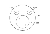
- FIG. 2 is a plan view showing a distal end surface of the endoscope insertion portion.
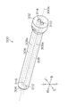
- FIG. 3 is an external perspective view showing a mantle tube.
- FIG. 4 is a cross-sectional view showing a reference form which is a reference of the embodiment of the present invention regarding the internal structure of the mantle tube.
- FIG. 5 is an enlarged sectional view showing a part of FIG. 4 in an enlarged manner.
- 6 is a cross-sectional view taken along the line VI-VI in FIG.
- FIG. 7 is a perspective view showing the slider (interlocking member) in the reference form of FIG. 4 from the upper left rear direction.
- FIG. 1 is a schematic configuration diagram of an endoscopic surgical apparatus according to an embodiment.
- FIG. 2 is a plan view showing a distal end surface of the endoscope insertion portion.
- FIG. 3 is an external perspective view showing a mantle tube.
- FIG. 8 is a perspective view showing the slider (interlocking member) in the reference form of FIG. 4 from the upper right rear direction.
- FIG. 9 is an explanatory diagram used for explaining the action of the slider (interlocking member) in the reference embodiment of FIG.
- FIG. 10 is an explanatory diagram used for explaining the action of the slider (interlocking member) in the reference embodiment of FIG.
- FIG. 11 is an explanatory diagram used for explaining the action of the slider (interlocking member) in the reference embodiment of FIG. FIG.
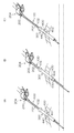
- FIG. 12 is an explanatory view showing a state of an operation when performing a treatment of an affected part in a body cavity of a patient using an endoscopic surgical apparatus, and (A) part shows a state before the operation; Part (B) shows a state in which the treatment instrument insertion part is operated forward in the dead zone area, and part (C) shows a state in which the treatment instrument insertion part is operated backward in the dead zone area.
- FIG. 12 shows an explanatory view showing a state of an operation when performing a treatment of an affected part in a body cavity of a patient using an endoscopic surgical apparatus, and (A) part shows a state before the operation; Part (B) shows a state in which the treatment instrument insertion part is operated forward in the dead zone area, and part (C) shows a state in which the treatment instrument insertion part is operated backward in the dead zone area.
- FIG. 13 is an explanatory view showing the state of the operation when performing the treatment of the affected part in the body cavity of the patient using the endoscopic surgical apparatus, and the part (A) shows the state before the operation, Part (B) shows a state in which the treatment instrument insertion part is operated forward in the sensitive zone area, and part (C) shows a state in which the treatment instrument insertion part is operated backward in the sensitive band area.
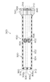
- FIG. 14 is a cross-sectional view showing the configuration of the interlocking member according to the embodiment of the present invention in a cross section obtained by cutting the mantle tube along the reference axis.
- FIG. 15 is an enlarged view showing an enlarged peripheral portion of the interlocking member in FIG.
- FIG. 16 is a cross-sectional view taken along arrow XVI-XVI in FIG.
- FIG. 17 is a cross-sectional view showing a resistance generating portion.
- FIG. 18 is an explanatory view used for explaining the operation of the interlocking member according to the embodiment of the present invention.
- FIG. 19 is an explanatory diagram used for explaining the operation of the interlocking member according to the embodiment of the present invention.
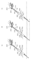
- FIG. 20 is an explanatory view used for explaining the operation of the interlocking member according to the embodiment of the present invention, in which (A) part shows a state in which the connecting member is in a natural length, and (B) part shows a treatment instrument insertion part.
- FIG. 21 is an explanatory view used for explaining the operation of the interlocking member according to the embodiment of the present invention, in which (A) part shows a state in which the connecting member is in a natural length, and (B) part shows a treatment instrument insertion part. The state immediately after moving forward greatly is shown, and part (C) shows the state after stopping and holding the treatment instrument insertion part after moving forward.
- FIG. 22 is a diagram showing another embodiment of the connecting member in the interlocking member according to the embodiment of the present invention.
- FIG. 23 is a view showing a state in which the connecting member of FIG. 22 is extended from the natural length.
- FIG. 24 is a view showing a state where the connecting member of FIG. 22 is compressed from the natural length.
- FIG. 25 is a view showing another embodiment of the second sleeve in the interlocking member according to the embodiment of the present invention.
- FIG. 1 is a schematic configuration diagram of an endoscopic surgical apparatus according to the present embodiment.
- an endoscopic surgical apparatus 10 includes an endoscope 100 that observes the inside of a patient's body cavity as one form of a first medical instrument, and a body cavity of the patient as one form of a second medical instrument.
- the first medical instrument and the second medical instrument guided by the outer tube 300 into the body cavity are not limited to a specific type, and the first medical instrument having the first insertion portion inserted into the body cavity and the body cavity Any type of second medical instrument having a second insertion portion inserted therein can be used.
- the endoscope 100 is a rigid endoscope such as a laparoscope, for example, and is inserted into a body cavity and has an insertion portion 102 (hereinafter referred to as an “endoscope insertion portion 102”) surrounded by an elongated rigid cylindrical body. And a cable portion 104 connected to the proximal end side of the endoscope insertion portion 102 and having an outer peripheral portion surrounded by an elongated soft cylindrical body.
- the cable portion 104 is a flexible cable in which a cable extending from the proximal end of the endoscope insertion portion 102 or a wire material such as a light guide is covered with a soft insulating member such as polyvinyl chloride and accommodated inside. Indicates the part.
- a connector (not shown) is provided at the end of the extension of the cable portion 104, and the processor device 108 and the light source device 110, which are control devices, are detachably connected via the connector.
- the processor device 108 is connected to the monitor 112 via a cable.
- an observation window 116 and illumination windows 118 and 118 are provided on the distal end surface 114 of the endoscope insertion portion 102.
- the observation window 116 is a component of the observation unit of the endoscope 100. Behind the observation window 116 is an objective lens of the observation optical system and a CCD (Charge Coupled Device) arranged at the imaging position of the objective lens.
- a solid-state imaging device such as an image sensor or a CMOS (Complementary Metal Oxide Semiconductor) image sensor is provided.
- a signal cable (not shown) connected to the solid-state image sensor is inserted through the endoscope insertion portion 102 and the cable portion 104 of FIG. 1 to a connector (not shown), and is connected to the processor device 108.
- the observation image captured from the observation window 116 is formed on the light receiving surface of the image sensor and converted into an electrical signal (imaging signal), and the electrical signal is output to the processor device 108 via the signal cable to be converted into a video signal. Converted.
- the video signal is output to the monitor 112 connected to the processor device 108, and an observation image (endoscopic image) is displayed on the screen of the monitor 112.
- the exit end of a light guide (not shown) is disposed behind the illumination windows 118 and 118 in FIG.
- the light guide is inserted through the endoscope insertion portion 102 and the cable portion 104 of FIG. 1 and has an incident end disposed in a connector (not shown). Accordingly, by connecting this connector to the light source device 110, the illumination light emitted from the light source device 110 is transmitted to the illumination windows 118 and 118 via the light guide, and is emitted forward from the illumination windows 118 and 118.
- two illumination windows 118 and 118 are disposed on the distal end surface 114 of the endoscope insertion portion 102, but the number of illumination windows 118 is not limited, and the number is one. It may be three or more.
- the treatment instrument 200 is made of forceps, for example, and is an elongated insertion section 202 (hereinafter referred to as “treatment instrument insertion section 202”) inserted into a body cavity, and a proximal end of the treatment instrument insertion section 202.
- treatment instrument insertion section 202 elongated insertion section 202
- An operation unit 204 provided on the side and grasped by an operator, and a treatment unit 206 provided on the distal end side of the treatment instrument insertion unit 202 and operable by operation of the operation unit 204.
- the treatment instrument insertion portion 202 is provided with a cylindrical sheath 208 and an operation shaft (not shown) that is inserted into the sheath 208 so as to be movable in the axial direction.
- the operation unit 204 is provided with a fixed handle 210 and a movable handle 214 that is rotatably connected to the fixed handle 210 via a rotation pin. The proximal end portion of the operation shaft is connected to the movable handle 214.
- the treatment section 206 is provided with a pair of gripping members that can be opened and closed. These grip members are connected to the tip of the operation shaft via a drive mechanism (not shown). Then, as the movable handle 214 of the operation unit 204 is rotated, the gripping member of the treatment unit 206 is opened and closed via the operation shaft and the drive mechanism.
- the treatment tool 200 is not limited to forceps, and may be other treatment tools such as a laser probe, a suture instrument, an electric knife, a needle holder, an ultrasonic device, and an aspirator.
- the outer tube 300 is fed out from the distal end side through the endoscope insertion portion 102 and the treatment instrument insertion portion 202 inserted inside from the proximal end side.
- the outer tube 300 is inserted into the body wall, the proximal end side is placed outside the body, and the distal end side is placed in the body cavity, so that the endoscope insertion portion 102 and the treatment instrument insertion portion 202 can be connected with one outer tube 300.
- the outer tube 300 has an interlocking function for moving the endoscope insertion portion 102 and the treatment instrument insertion portion 202 in conjunction with each other as will be described in detail later. For example, the advancement / retraction of only the treatment instrument insertion portion 202 is performed.
- the endoscope insertion unit 102 can also be moved forward and backward by the operation, and an appropriate endoscopic image can be obtained without performing the forward / backward operation of the endoscope insertion unit 102. Details of the configuration and operation of the outer tube 300 will be described later.
- FIG. 3 is an external perspective view showing the outer tube 300.
- the outer tube 300 has an elongated cylindrical shape as a whole, and is inserted into the endoscope 100 in parallel with a reference axis 300a indicating a longitudinal axis that is a central axis thereof.
- An endoscope insertion path 306 through which the portion 102 is inserted in a retractable manner and a treatment instrument insertion path 308 through which the treatment instrument insertion portion 202 of the treatment instrument 200 is inserted in an advanceable and retractable manner are provided.
- the central axis of the endoscope insertion path 306 is referred to as an endoscope insertion axis 306a and the central axis of the treatment instrument insertion path 308 is referred to as a treatment instrument insertion axis 308a
- the endoscope insertion axis 306a and the treatment instrument insertion axis 308a is parallel to each other and is also parallel to the reference axis 300a.
- the endoscope insertion shaft 306a and the treatment instrument insertion shaft 308a are the central axes of the endoscope insertion section 102 and the treatment instrument insertion section 202 inserted through the endoscope insertion path 306 and the treatment instrument insertion path 308, respectively. Corresponds to position.
- the reference shaft 300a, the endoscope insertion shaft 306a, and the treatment instrument insertion shaft 308a are arranged on the same plane.
- the reference shaft 300a, the endoscope insertion shaft 306a, and the treatment instrument insertion shaft 308a may not be arranged on the same plane.
- the direction from the proximal end surface 302 to the distal end surface 304 in the direction along the reference axis 300a is the front, and the direction from the reference axis 300a to the endoscope insertion shaft 306a.
- the direction from the reference axis 300a to the endoscope insertion shaft 306a are left, front, back, left, right, top, and bottom.
- the proximal end surface 302 of the outer tube 300 has a first proximal end opening 310 that is a proximal end opening for inserting the endoscope insertion portion 102 into the endoscope insertion passage 306, and the treatment instrument insertion portion 202 as the treatment instrument insertion passage 308. And a second base end opening 314 which is a base end opening to be inserted into the first base end opening.
- the distal end surface 304 of the outer tube 300 is inserted into the first distal end opening 312 which is the distal end opening for feeding out the endoscope insertion portion 102 inserted into the endoscope insertion passage 306 and the treatment instrument insertion passage 308.
- a second distal end opening 316 which is a distal end opening for feeding the treatment instrument insertion portion 202 to the outside is provided.
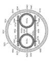
- FIG. 4 is a cross-sectional view showing a reference form of the internal structure of the outer tube 300, which is cut along a plane including the reference axis 300a and perpendicular to the vertical direction (cut in the left-right direction along the reference axis 300a). ) Shows a cross section.
- the mantle tube 300 is attached to the mantle tube long cylindrical body 320 occupying substantially the entire front and rear direction, a base end cap 340 attached to the rear end (base end) of the mantle tube 300, and the tip portion. It has a tip cap 360 and a slider 400 which is a form of an interlocking member disposed inside the outer tube 300.
- the outer tube 320 is formed of a hard resin, metal, or the like into a long and thin cylindrical shape having the reference axis 300a as the center axis, and penetrates from the base wall to the tip of the outer tube 320 and the outer wall 322 surrounding the outer periphery. And a cavity portion 324 that has a cavity.
- the hollow portion 324 encloses a space serving as the endoscope insertion path 306 and the treatment instrument insertion path 308 and accommodates the slider 400 and the like.
- the proximal end cap 340 is formed in a columnar shape whose diameter is larger than the outer diameter of the outer cannula tube 320 by a hard resin, metal, or the like, and its rear end surface constitutes the proximal end surface 302 of the outer tube 300.
- the proximal cap 340 is provided with a through hole 342 and a through hole 344 that form a part of the endoscope insertion path 306 and the treatment instrument insertion path 308.
- the opening of the through hole 342 corresponds to the first base end opening 310 described above
- the opening of the through hole 344 corresponds to the second base end opening 314 described above.
- valve members 346 and 348 are provided in the through holes 342 and 344, respectively. These valve members 346 and 348 are opened only when the endoscope insertion portion 102 and the treatment instrument insertion portion 202 are inserted, for example, and the outer peripheral surfaces (side surfaces) of the endoscope insertion portion 102 and the treatment instrument insertion portion 202 are opened. Close contact with almost no gap. As a result, the airtightness of the space on the distal end side relative to the valve members 346 and 348 is ensured, and leakage or the like of the pneumoperitone gas injected into the body cavity is reduced.
- the front end cap 360 is formed of hard resin, metal, or the like, and the front end surface thereof constitutes the front end surface 304 of the outer tube 300.
- the distal end cap 360 is provided with a through hole 362 and a through hole 364 that form part of the endoscope insertion path 306 and the treatment instrument insertion path 308.
- the opening of the through hole 362 corresponds to the first tip opening 312 described above, and the opening of the through hole 364 corresponds to the second tip opening 316.
- tip cap 360 show one form of the structural member which comprises the outer tube 300, and the outer tube 300 is not restricted to the structure of this Embodiment.
- the outer tube long cylinder 320 and the base end cap 340, or the outer tube long tube 320 and the distal end cap 360 may be integrally formed, or may be integrally formed as a whole.
- the outer tube 300 has a cylindrical shape through which the first insertion portion of the first medical instrument and the second insertion portion of the second medical instrument are inserted, and guides the first insertion portion and the second insertion portion into the body cavity. Anything is acceptable.
- the slider 400 is accommodated in the outer tube 320 (hollow portion 324), and is supported so as to be able to advance and retract in the direction of the reference shaft 300a.
- the slider 400 is connected to the endoscope insertion portion 102 inserted into the endoscope insertion passage 306 and the treatment instrument insertion portion 202 inserted into the treatment instrument insertion passage 308, so that the endoscope insertion portion 102 and the treatment are connected.
- An embodiment of an interlocking member that interlocks with the tool insertion part 202 and moves forward and backward in the front-rear direction (axial direction) is shown.
- the slider 400 includes a dead zone region in which one of the endoscope insertion portion 102 and the treatment instrument insertion portion 202 is not interlocked with the forward / backward movement in the front-rear direction (axial direction), that is, independently moves.
- the other has a sensitive zone that interlocks with the forward and backward movement, and in the dead zone, the relative position of the distal end of the endoscope 100 with respect to the distal end of the treatment instrument 200 with respect to the reference axis 300a direction of the outer tube 300 is determined. It is an interlocking member that changes.
- the endoscope insertion portion 102 is interlocked with play by the slider 400 with respect to the forward and backward movement of the treatment instrument insertion portion 202 in the axial direction.
- FIG. 5 is an enlarged cross-sectional view showing an enlarged portion where the slider 400 is arranged in FIG. 4, and the endoscope insertion portion 102 and the treatment in each of the endoscope insertion passage 306 and the treatment instrument insertion passage 308. The state which penetrated the tool insertion part 202 is shown. 6 is a cross-sectional view taken along the line VI-VI in FIG.
- FIG 7 and 8 are perspective views showing the slider 400 from the upper left rear direction and the rear upper right direction, respectively.
- the slider 400 includes a slider body 402 that holds the components of the slider 400. As shown in FIG. 6, on the flat upper surface 404 (see FIGS. 7 and 8) and the lower surface 406 of the slider body 402, ridges 408 and 410 extending in the reference axis 300 a direction (front-rear direction) are formed.
- a pair of left and right long guide plates 374 and 374 shown in FIG. 6 spanned between the base end cap 340 and the front end cap 360 are respectively provided on the upper and lower portions in the outer tube long cylinder 320.
- the guide plates 376 and 376 are supported, and the reference shaft 300a from the proximal cap 340 to the distal cap 360 is formed by the gap between the guide plates 374 and 374 and the gap between the guide plates 376 and 376.
- Guide grooves 370 and 372 extending in the direction are formed.
- the protruding portions 408 and 410 of the slider main body 402 are fitted into the guide grooves 370 and 372 in the outer tube body 320, and the upper surface 404 and the lower surface 406 are guide plates 374 and 374, and 376 and 376, respectively. It is arranged in contact with or close to.
- the slider 400 is supported so as to be movable back and forth in the longitudinal direction of the outer tube 320, and moved in the vertical and horizontal directions and rotated in all directions (front and rear, left and right, and up and down three axes). Is regulated (at least in a state where rotation around the reference axis 300a is impossible). Further, the slider 400 moves forward and backward within a movable range in which the position where it abuts on the base end cap 340 is the rear end and the position where it abuts on the distal end cap 360 is the front end.
- the guide grooves 370 and 372 are not formed by the guide plates 374, 374, 376 and 376 arranged in the outer tube long cylinder 320, but are formed in the outer wall 322 of the outer tube long cylinder 320. It may also be formed by other configurations.
- the slider 400 includes a left endoscope connecting portion 420 that is connected (engaged) with the endoscope insertion portion 102 and a right treatment that is connected (engaged) with the treatment instrument insertion portion 202. And a tool connecting portion 422.
- the endoscope connecting portion 420 provided on the left side of the slider main body 402 secures a space that becomes the endoscope insertion passage 306 in the outer tube 320, and the endoscope insertion portion 102 as shown in FIG. Is inserted into the through hole 424 (see FIGS. 6, 7, and 8) and the outer peripheral surface (side surface) of the endoscope insertion portion 102 that is fixed to the through hole 424 and inserted into the endoscope insertion passage 306.
- the pressure contact member 426 is formed in a cylindrical shape by an elastic material such as elastic rubber as shown in FIGS. 6 and 7, and the opening 430 formed in the left side surface 431 of the slider main body 402 as shown in FIG.
- the slider body 402 is fixed by being fitted to a position coaxial with the through hole 424.
- the endoscope insertion portion 102 when the endoscope insertion portion 102 is inserted through the endoscope insertion passage 306, the endoscope insertion portion 102 passes through the through hole 424 as shown in FIG.
- the press contact member 426 is press contacted (engaged) with the outer peripheral surface, and the central axis of the endoscope insertion portion 102 is arranged coaxially with the endoscope insertion shaft 306a.
- the endoscope insertion portion 102 and the slider 400 (slider main body 402) are coupled (engaged) in an interlocking manner via the pressure contact member 426, and the endoscope insertion portion 102 is advanced and retracted in the front-rear direction (axial direction). In conjunction with the movement, the slider 400 (slider main body 402) also moves forward and backward integrally.
- the position at which 400 is engaged can be arbitrarily adjusted.
- the treatment instrument connecting portion 422 provided on the right side of the slider main body 402 includes a sleeve 440 (see FIGS. 6 and 8) connected to the treatment instrument insertion portion 202 and a sleeve 440 as shown in FIG. And a guide portion 460 that guides the guide so as to be movable forward and backward.
- the sleeve 440 includes a sleeve main body 444 (frame body) formed in a cylindrical shape, and a pressure contact member 446 fixed to the inside of the sleeve main body 444.
- the pressure contact member 446 is formed in a cylindrical shape by an elastic material such as elastic rubber.
- the treatment instrument insertion portion 202 when the treatment instrument insertion portion 202 is inserted into the treatment instrument insertion path 308, the treatment instrument insertion portion 202 is inserted through the inside of the pressure contact member 446 (through hole 450 in FIG. 6) as shown in FIG.
- the pressure contact member 446 is in pressure contact (engagement) with the outer peripheral surface of the treatment instrument insertion portion 202, and the central axis of the treatment instrument insertion portion 202 is arranged coaxially with the treatment instrument insertion shaft 308a.
- the treatment instrument insertion portion 202 and the sleeve 440 are connected to each other via a pressure contact member 446 so that the treatment instrument insertion portion 202 can be interlocked, and the sleeve 440 is also integrally interlocked with the forward and backward movement of the treatment instrument insertion portion 202 in the front-rear direction (axial direction). Move forward and backward.
- the sleeve 440 rotates with respect to the slider main body 402 in conjunction with the rotation around the axis of the treatment instrument insertion portion 202.
- connection between the treatment instrument insertion portion 202 and the sleeve 440 is due to the elastic force of the pressure contact member 446, and therefore, the engagement position of the treatment instrument insertion portion 202 connected to the sleeve 440 (the treatment instrument insertion portion).
- the position at which the sleeve 440 is engaged at 202 can be arbitrarily adjusted.
- the guide portion 460 of the treatment instrument connecting portion 422 is, as shown in FIGS. 6 and 8, the slider body 402 extending in the direction of the reference axis 300a (treatment instrument insertion shaft 308a) in the hollow portion 324 of the outer tube 320. Is formed by a space surrounded by the guide surface 462 and the inner peripheral surface of the outer tubular tube 320.
- the sleeve 440 is accommodated and disposed in the space of the guide portion 460, is supported so as to be movable in the front-rear direction and to be rotatable around the axis, and is supported in a state where movement in the vertical and horizontal directions is restricted.
- guide portion 460 is provided so as to be within a range from the proximal end to the distal end of the slider main body 402, and as shown in FIGS. 5 and 8, guide portions 460 are provided on the proximal end side and the distal end side of the slider main body 402, respectively. End edges 466 and 468 are formed along the edge of the surface 462 so as to project in a direction perpendicular to the guide surface 462.
- end edge portions 466 and 468 abut against the end portion of the sleeve 440 and restrict the movement of the sleeve 440 when the sleeve 440 disposed in the space of the guide portion 460 moves forward and backward.
- the sleeve 440 moves back and forth within a movable range in which the position where the end edge 466 abuts is the rear end and the position where the end edge 468 abuts is the front end.
- the mantle tube 300 is inserted into the body wall of the patient, and insufflation gas is injected into the body cavity.
- the endoscope 100 (endoscope insertion part 102) and the treatment tool 200 (treatment tool insertion part 202) are inserted into each of the tool insertion passages 308, and the endoscope insertion part 102 and the treatment tool are inserted into the outer tube 300.
- the unit 202 is attached.
- the endoscope insertion portion 102 is connected to the slider main body 402 of the slider 400, and the treatment instrument insertion portion 202 is connected to the sleeve 440 of the slider 400.
- the state of the part (A) in FIG. 12 is a state in which the sleeve 440 has not reached either the front end or the rear end of the movable range with respect to the slider main body 402 (guide part 460) as shown in FIG. Then, when the surgeon makes a slight advance of the treatment instrument insertion section 202 with the hand holding the operation section 204 of the treatment instrument 200, the slider main body 402 moves relative to the outer tube 300 (outer tube long tubular body 320). Without moving, only the sleeve 440 moves forward with respect to the slider body 402 within a movable range with respect to the slider body 402.
- the endoscope insertion portion 102 is moved as shown in FIG. Only the treatment instrument insertion portion 202 advances in a stationary state. That is, the slider 400 has a dead zone area where the endoscope insertion section 102 is not interlocked with the advance / retreat movement of the treatment instrument insertion section 202, and the forward operation of the treatment instrument 200 at this time advances / retreats in the dead zone area of the slider 400. It becomes operation.
- the surgeon can When the treatment instrument insertion unit 202 is slightly retracted with the hand holding the operation unit 204, the slider main body 402 does not move with respect to the outer tube 300 (outer tube long tubular body 320), but with respect to the slider main body 402. Only the sleeve 440 moves backward within a movable range with respect to the slider body 402.
- the endoscope 100 does not move back and forth with respect to a minute advance / retreat operation of the treatment instrument 200, that is, an advance / retreat operation in the dead zone region, and thus the treatment instrument 200 displayed as an endoscopic image on the monitor 112.
- the range of the observation site such as the distal end site or the body cavity site does not change, and the size of the image of the observation site can be prevented from changing according to the minute displacement of the treatment tool 200.
- a sense of perspective can be appropriately maintained, and a stable endoscopic image can be obtained.
- the sleeve 440 and the slider main body 402 move forward together with the treatment instrument insertion portion 202 with respect to the outer tube 320, and the endoscope insertion portion 102 moves to the treatment instrument insertion portion. It moves forward in conjunction with 202.
- FIG. 13A shows the same state as the portion (A) of FIG.
- the endoscope insertion portion 102 moves forward in conjunction with the treatment instrument insertion portion 202 as shown in FIG. That is, the slider 400 has a sensitive zone region in which the endoscope insertion portion 102 is interlocked with the advance and retreat movement of the treatment instrument insertion portion 202, and the forward operation of the treatment instrument 200 at this time is the sensitive zone region of the slider 400. This is a forward operation.
- the operator holds the operation unit 204 of the treatment instrument 200.
- the sleeve 440 is moved back in the dead zone until the sleeve 440 of the slider 400 comes into contact with the rear end of the movable range, as shown in FIG. The rear end of the movable range with respect to the main body 402 is reached.
- the sleeve 440 and the slider main body 402 move backward with respect to the outer tube tube 320 together with the treatment tool insertion portion 202, and the endoscope insertion portion 102 moves to the treatment instrument insertion portion. It moves backward in conjunction with 202.
- the endoscope insertion portion 102 moves backward. That is, the backward operation of the treatment instrument 200 at this time is a backward operation in the zone of the slider 400.
- the endoscope 100 moves forward / backward, so that the observation reflected in the endoscopic image displayed on the monitor 112 is observed.
- the range of the part is continuously changed so as to follow the advance / retreat movement of the treatment instrument 200.
- the size of the image of the observation region other than the distal end portion of the treatment tool 200 and the size of the range of the observation region that are reflected in the endoscopic image change according to the operation of the treatment device 200, so that the operator desires Images can be easily obtained.
- the endoscope insertion portion 102 moves forward and backward in conjunction with the front, rear, up, down, left and right, the field of view and orientation of the endoscope 100 can be changed as intended by the operator.
- the visual field always images the distal end portion of the treatment tool 200, and an optimal image for treatment is automatically provided.
- an optimal image for treatment is automatically provided.
- an assistant who operates the endoscope 100 separately from the surgeon can be eliminated, and the surgeon must sequentially indicate the field of view, orientation, and the like of the endoscope 100 to the assistant. The troublesomeness can be eliminated.
- the endoscope insertion unit 102 does not interlock, and thus the endoscope image changes unnecessarily. Can be prevented, a sense of perspective can be appropriately maintained, and a stable endoscopic image can be provided.
- the slider 400 is employed as an interlocking member for interlocking the endoscope insertion portion 102 and the treatment instrument insertion portion 202.
- the slider 400 has a simple configuration.
- An interlocking member that is similar to the slider 400 and that is similar to the slider 400 is employed.
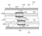
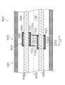
- FIG. 14 is a cross-sectional view showing the configuration of the interlocking member 600 according to the embodiment of the present invention in a cross-section obtained by cutting the outer tube 300 along the reference axis 300a
- FIG. 15 is a cross-sectional view of the interlocking member 600 in FIG. It is the enlarged view which expanded and showed the peripheral part.
- 16 is a cross-sectional view taken along arrow XVI-XVI in FIG.
- FIG. 15 shows a state in which the endoscope insertion section 102 and the treatment instrument insertion section 202 are inserted through the endoscope insertion path 306 and the treatment instrument insertion path 308 of the outer tube 300.
- the interlocking member 600 includes a first sleeve 602 as a first holding portion for holding the endoscope insertion portion 102 inserted through the endoscope insertion passage 306 of the outer tube 300, and the outer tube 300.
- a second sleeve 604 as a second holding portion for holding the treatment instrument insertion portion 202 inserted through the treatment instrument insertion path 308, and a connecting member 606 for connecting the first sleeve 602 and the second sleeve 604.
- the first sleeve 602 is configured in the same manner as the sleeve 440 in the slider 400 of the above-described reference embodiment, and a sleeve main body 620 that is a cylindrical frame as shown in FIGS. 15 and 16, and the sleeve main body 620.
- a pressure contact member 622 that is fixed inside and formed in a cylindrical shape by an elastic material.
- the second sleeve 604 is a cylindrical frame body 640 as shown in FIGS. 15 and 16, and a sleeve body 640 is fixed to the inside of the sleeve body 640, and is pressed into a cylindrical shape by an elastic material. Member 642.
- the upper and lower portions of the outer tube 300 are formed by the guide plates 374 and 374 and the guide plates 376 and 376 shown in FIG. Similar to the guide grooves 370 and 372, guide plates 660, 662 and 664 extending along the direction of the reference axis 300a between the proximal cap 340 and the distal end cap 360, and guide plates 666, 668 and 670 are provided.
- the guide plates 660, 662, and 664 and the guide plates 666, 668, and 670 are extended to form guide grooves 672 and 674 that extend along the direction of the reference axis 300a, and guide grooves 676 and 678.
- protruding strips 680 and 682 extending in the direction of the shaft 300a (front-rear direction) are formed.
- Each of the ridges 680 and 682 is inserted into the guide grooves 672 and 676, and the outer peripheral surface of the first sleeve 602 is disposed in contact with or close to the guide plates 660, 662, 666, and 668.
- convex strips 684 and 686 extending in the direction of the shaft 300a (front-rear direction) are formed on the upper and lower portions of the outer peripheral surface of the second sleeve 604 (sleeve body 640).
- Each of the ridges 684 and 686 is inserted into the guide grooves 674 and 678, and the outer peripheral surface of the second sleeve 604 is disposed in contact with or close to the guide plates 662, 664, 668 and 670.
- the first sleeve 602 is supported so that its central axis is arranged substantially coaxially with the endoscope insertion shaft 306a, can move forward and backward in the front-rear direction, and cannot rotate around the central axis.
- the center axis of the second sleeve 604 is disposed substantially coaxially with the treatment instrument insertion shaft 308a, and is supported so that it can move forward and backward in the front-rear direction and cannot rotate around the center axis.
- the mechanism for supporting the first sleeve 602 and the second sleeve 604 so as to be able to advance and retreat in the direction of the reference axis 300a of the outer tube 300 may be different from the present embodiment.
- the treatment instrument insertion portion 202 when the treatment instrument insertion portion 202 is inserted into the treatment instrument insertion passage 308, the treatment instrument insertion portion 202 is inserted into the through hole 604 a of the second sleeve 604 (the through hole on the inner peripheral side of the pressure contact member 642. 604a, see FIG. 16), and the pressure contact member 642 presses (engages) the outer peripheral surface of the treatment instrument insertion portion 202. Thereby, the 2nd sleeve 604 and the treatment tool insertion part 202 connect.
- connection between the first sleeve 602 and the endoscope insertion portion 102 and the connection between the second sleeve 604 and the treatment instrument insertion portion 202 are due to the elastic force of the pressure contact members 622 and 642.
- the position where the first sleeve 602 is connected in the endoscope insertion portion 102 and the position where the second sleeve 604 is connected in the treatment instrument insertion portion 202 can be arbitrarily adjusted.
- the connecting member 606 has one first end 606a fixed to the first sleeve 602 as a first fixing portion, and the other second end 606b as a second fixing portion. 2 It is fixed to the sleeve 604 and has an elastic body between the first end 606a and the second end 606b.
- the elastic body includes, for example, a rubber, a spring, a member using a metal elastic force, a member using an elastic force of a resin such as plastic, and a member using an elastic force of air.
- the first end 606a is, for example, the right side of the outer peripheral surface of the first sleeve 602 and is fixed near the center in the front-rear direction
- the second end 606b is, for example, the left side of the outer peripheral surface of the second sleeve 604 It is fixed on the side and near the center in the front-rear direction.
- first fixing position in the first sleeve 602 to which the first end 606a is fixed and the second fixing position in the second sleeve 604 to which the second end 606b is fixed are not limited to specific positions.
- the connecting member 606 changes in expansion / contraction state according to the relative movement of the first sleeve 602 and the second sleeve 604 in the front-rear direction, and the extension between the first end portion 606a and the second end portion 606b becomes longer as it extends. Increase tensile force.
- the connecting member 606 is connected to the first sleeve 602 when the first end portion 606a and the second end portion 606b of the connecting member 606 are aligned in the front-rear direction.
- a reference state in which a tensile force in the direction of the reference axis 300a (front-rear direction) is not generated between the second sleeve 604 and the second sleeve 604 is provided.
- the distance between the first end portion 606a and the second end portion 606b when the connecting member 606 is in its reference state is expressed as L1 as a natural length, and this state is expressed by the connecting member 606 having the natural length L1.
- L1 the natural length
- the natural length L1 here does not necessarily indicate the length when no load is applied to the connecting member 606, and the first end 606a and the first end when the connecting member 606 is in the natural length L1 state.
- a state in which a tensile force acts between the two end portions 606b may be used.
- the distance between the portion 606a and the second end portion 606b is represented by L2, and this state is a state in which the connecting member 606 has a length L2.
- the connecting member 606 urges the first end 606a and the second end 606b toward each other along the reference axis 300a direction (front-rear direction) of the outer tube 300. To generate power.
- connection member 606 becomes longer than L1
- the force for urging the first end portion 606a and the second end portion 606b toward each other along the front-rear direction increases.
- the responsiveness of the interlocking movement of the first sleeve 602 with respect to the movement of the second sleeve 604 in the front-rear direction becomes faster.
- the smaller the amount of movement that is, the smaller the difference between the length L2 of the connecting member 606 and the natural length L1, the slower the response.
- the response of the interlocking of the first sleeve 602 to the movement of the second sleeve 604 in the front-rear direction (hereinafter referred to as the response of the first sleeve 602 to the second sleeve 604) is the front-rear direction of the first sleeve 602.
- the outer tube 300 is provided with a resistance generating portion for generating such resistance in order to moderately slow down the response.
- the resistance generating portion is formed in the through hole 362 (the through hole 362 of the distal end cap 360) in the vicinity of the first distal end opening 312 of the outer tube 300 in which the endoscope insertion portion 102 is drawn out from the outer tube 300. 608 is provided.
- the resistance generation unit 608 is formed of, for example, a friction body, and is inserted into the endoscope insertion passage 306 so as to contact a part or the whole of the circumferential direction with the endoscope insertion unit 102 to which the first sleeve 602 is connected. Provided.
- the endoscope insertion portion 102 moves in the front-rear direction together with the first sleeve 602
- the endoscope insertion portion 102 slides on the resistance force generation portion 608 and receives a resistance force due to friction.
- the resistance force is applied to the first sleeve 602 via the endoscope insertion portion 102.
- the magnitude of the resistance force generated by the resistance force generation unit 608 can be adjusted by the contact area between the resistance force generation unit 608 and the endoscope insertion unit 102, and the magnitude of the resistance force is adjusted.
- the response of the first sleeve 602 to the second sleeve 604 is adjusted to be appropriate.
- the resistance force generation unit is configured by a friction body, but is not limited thereto, and is configured by, for example, a viscous body such as a dashpot, or a combination thereof. May be.
- such a resistance generating portion is provided between a member constituting the outer tube 300 and the endoscope insertion portion 102 inserted through the outer tube 300, or a member constituting the outer tube 300 and the first sleeve 602. It may be provided in any portion between the two, and may not be a special component added to generate a resistance force.
- the endoscope insertion passage 306 of the outer tube 300 is provided with a valve member 346 (valve member 346 in the proximal cap 340) that ensures airtightness of the inner space of the outer tube 300. Since this valve member 346 is slidably contacted with the endoscope insertion portion 102, it can be used as a resistance generating portion.
- the outer peripheral surface of the first sleeve 602 (the outer peripheral surface of the sleeve body 6209) is in contact with or close to the inner peripheral surface of the outer tube 320, or the guide plates 660, 662, 666, and 668. Placed in a state. Therefore, a resistance force generating portion that contacts any of the outer tube tube 320 and the guide plates 660, 662, 666, and 668 can be provided on the outer peripheral surface of the first sleeve 602.
- the resistance generating portion may be provided on one or both of the first sleeve 602 and the second sleeve 604.
- the endoscope insertion portion 102 moves forward and backward in the same manner as the response of the first sleeve 602 to the second sleeve 604.
- the responsiveness of the second sleeve 604 with respect to the first sleeve 602 can also be adjusted.
- interlocking member 600 The operation of the interlocking member 600 according to the embodiment of the present invention will be described.
- the outer tube 300 on which the interlocking member 600 of this embodiment is mounted is attached to the patient.
- the endoscope 100 endoscope insertion portion 102
- the treatment instrument 200 treatment instrument insertion section 202
- the outer tube 300 is fitted with the endoscope insertion section 102 and the treatment instrument insertion section 202.
- the endoscope insertion portion 102 is connected to the first sleeve 602, and the treatment instrument insertion portion 202 is connected to the second sleeve 604.
- the state of the interlocking member 600 in the part (A) of FIG. 20 is a state in which the positions in the front-rear direction of the first end part 606a and the second end part 606b of the connecting member 606 substantially coincide as shown in FIG. That is, it is assumed that the connecting member 606 is in the natural length L1.
- the surgeon makes a slight advance of the treatment instrument insertion section 202 with the hand holding the operation section 204 of the treatment instrument 200, immediately after that, the difference between the length L2 of the connecting member 606 and the natural length L1. Since the first sleeve 602 is slow in response to the second sleeve 604, the first sleeve 602 is substantially stopped with respect to the outer tube 300.
- the connecting member 606 expands by the forward movement of the second sleeve 604, and the first sleeve 602 moves backward relative to the second sleeve 604. That is, the difference between the length L2 of the connecting member 606 and the natural length L1 gradually increases.
- the first force of the connection member 606 is caused by the tensile force of the connection member 606.
- the first sleeve 602 moves forward so that the end portion 606a and the second end portion 606b approach each other, that is, the difference between the length L2 of the connecting member 606 and the natural length L1 becomes zero.
- the interlocking member 600 forms a low response region where the endoscope insertion portion 102 is not temporarily interlocked with a minute advance / retreat operation of the treatment instrument insertion portion 202.
- the interlocking member 600 has a position in the front-rear direction between the first end 606 a and the second end 606 b of the connecting member 606 as shown in FIG. 15. It is assumed that they are substantially coincident, that is, the connecting member 606 is in a natural length L1.
- the length L2 of the connecting member 606 and the natural length are the same as in the above-described case where the treatment instrument insertion portion 202 is slightly moved forward. Since the difference from L1 is small and the response of the first sleeve 602 to the second sleeve 604 is slow, the first sleeve 602 is substantially stopped with respect to the outer tube 300.
- the connecting member 606 expands by the forward movement of the second sleeve 604, and the first sleeve 602 moves backward from the first position relative to the second sleeve 604. That is, the difference between the length L2 of the connecting member 606 and the natural length L1 gradually increases.
- the connecting member 606 further expands, and the difference between the length L2 of the connecting member 606 and the natural length L1 further increases.
- the tensile force of the connecting member 606 gradually increases, and the response of the first sleeve 602 to the second sleeve 604 gradually increases.
- the first sleeve 602 starts moving forward with respect to the outer tube 300, and the second sleeve 604 is moved forward.
- the second sleeve 604 moves forward with the forward movement.
- the state of FIG. 21A is the same as the state of FIG. As shown in part (B), after only the treatment instrument insertion section 202 advances slightly with the endoscope insertion section 102 substantially stopped, the endoscope insertion section 102 advances together with the treatment instrument insertion section 202.
- the first sleeve 602 continues to advance due to the tensile force of the connecting member 606. As shown in FIG. 15, when the front and rear positions of the first end 606a and the second end 606b of the connecting member 606 are substantially aligned, that is, the connecting member 606 is in the natural length L1 state, The forward movement of the first sleeve 602 stops.
- the interlocking member 600 forms a high response region for interlocking the endoscope insertion portion 102 with respect to the advance / retreat operation of the treatment instrument insertion portion 202 beyond the low response region.
- the endoscope insertion portion 102 moves forward and backward in conjunction with the left and right, the field of view and orientation of the endoscope 100 can be changed as intended by the operator.
- the visual field always images the distal end portion of the treatment tool 200, and an optimal image for treatment is automatically provided.
- an assistant who operates the endoscope 100 separately from the surgeon can be eliminated, and the surgeon must sequentially indicate the field of view, orientation, and the like of the endoscope 100 to the assistant. The troublesomeness can be eliminated.
- the endoscope insertion portion 102 is not temporarily interlocked, so that the small amplitude advance / retreat operation is performed. Can continue to prevent the endoscope insertion unit 102 from moving and the endoscope image from fluctuating unnecessarily, maintaining a proper perspective and providing a stable endoscope image. can do.
- the interlocking member 600 since the interlocking member 600 according to the embodiment of the present invention has a simpler structure than the case where the interlocking member is the slider 400, the cost of the outer tube 300 is reduced, the structure is simplified, and the diameter is reduced. be able to.
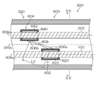
- the connecting member 606 connects the first sleeve 602 and the second sleeve 604 in a direction orthogonal to the reference shaft 300a as shown in FIG.
- it is not limited to this.
- a support member 700 protruding from the first sleeve 602 and a support portion 702 protruding from the second sleeve 604 are connected by a connecting member 710 in the direction of the reference axis 300a. May be.
- the first end 710a which is one end of the connecting member 710 and is the first fixing portion, is fixed to the first sleeve 602 via the support portion 700, and the other end of the connecting member 710 is the second fixing portion.
- the second end portion 710 b is fixed to the second sleeve 604 via the support portion 702.
- the connecting member 710 is, for example, a coil spring. In the state of the natural length L1 where the coil spring is not expanded and contracted as shown in the figure, the connecting member 710 is between the first sleeve 602 and the second sleeve 604 in the reference axis 300a direction (front-rear direction). It becomes the reference state that does not cause the force to.
- a distance between the portion 710a and the second end portion 710b is represented by L2, and this state is a state in which the connecting member 710 has a length L2.
- the connecting member 710 connects the first end 710a and the second end 710b to each other along the reference axis 300a direction (front-rear direction) of the outer tube 300. Generates a force that biases in the approaching direction.
- the connecting member 710 has a greater force for urging the first end 710a and the second end 710b closer to each other along the front-rear direction.
- the connecting member 710 moves the first end 710a and the second end 710b away from each other along the reference axis 300a direction (front-rear direction) of the outer tube 300. Generates a force that biases in the direction.
- the connecting member 710 has a greater force for urging the first end 710a and the second end 710b away from each other along the front-rear direction.
- the larger the amount of relative movement of the first sleeve 602 and the second sleeve 604 relative to the natural length L1 of the connecting member 710 is, that is, the connecting member.
- the greater the difference between the length L2 of 710 and the natural length L1 the faster the response of the interlocking of the first sleeve 602 to the movement of the second sleeve 604 in the front-rear direction.
- the smaller the amount of movement that is, the smaller the difference between the length L2 of the connecting member 606 and the natural length L1 the slower the response.
- either the support portion 700 of the first sleeve 602 or the support portion 702 of the second sleeve 604 may be disposed on the front side.
- the first sleeve 602 and the second sleeve 604 are restricted from rotating around the respective central axes, and the endoscope insertion portion 102 and the treatment tool connected to them are connected.
- the rotation of the insertion portion 202 around the axis is also restricted.
- either one or both of the endoscope insertion portion 102 and the treatment instrument insertion portion 202 may be rotatable about the axis.
- the second sleeve 604 may be configured as shown in the cross-sectional view of FIG.
- the second sleeve 604 includes the above-described cylindrical sleeve body 640, and a cylindrical intermediate frame 720 that is rotatably supported around the central axis with respect to the sleeve body 640 on the inner peripheral side of the sleeve body 640.
- the cylindrical pressure contact member 642 is fixed to the inner peripheral side of the intermediate frame 720.
- the first sleeve 602 can also be configured in the same manner as the second sleeve 604 in FIG.
- the reference shaft 300a, the endoscope insertion shaft 306a, and the treatment instrument insertion shaft 308a are parallel to each other. However, the endoscope insertion with respect to the reference shaft 300a is performed. At least one of the shaft 306a and the treatment instrument insertion shaft 308a may be oblique (non-parallel).
- a plane including the reference axis 300a and having the normal direction in the vertical direction is referred to as a horizontal reference plane
- a plane including the reference axis 300a and having the horizontal direction as the normal is referred to as a vertical reference plane
- the reference axis 300a, the endoscope insertion axis 306a, and the treatment instrument insertion axis 308a are all parallel to each other.
- the reference axis 300a and the treatment instrument insertion axis 308a are parallel to each other on the vertical reference plane when the endoscope insertion axis 306a and the treatment instrument insertion axis 308a are projected onto the vertical reference plane, but the reference axis 300a
- the endoscope insertion shaft 306a may be non-parallel, and the endoscope insertion shaft 306a may be inclined obliquely from the lower rear side toward the upper front side, for example.
- the outer tube 300 guides the endoscope insertion portion 102 in an oblique direction with respect to the guide direction of the treatment instrument insertion portion 202, and the distal end portion of the treatment portion 206 at the distal end of the treatment instrument insertion portion 202 is a blind spot.
- the distal end of the treatment section 206 is placed on the observation image by widening the interval between the observation section (observation window 116) at the distal end of the endoscope insertion section 102 and the treatment section 206 at the distal end of the treatment instrument insertion section 202 so Can be made visible.
- Endoscopic surgical apparatus 100 Endoscope 102 Endoscope insertion part 104 Cable part 108 Processor apparatus 110 Light source apparatus 112 Monitor 116 Observation window 118 Illumination window 200 Treatment tool 202 Treatment tool insertion part 204 Operation part 206 Treatment part 300 Outer tube 300a Reference shaft 302 Base end face 304 End face 306 Endoscope insertion path 306a Endoscope insertion shaft 308 Treatment instrument insertion path 308a Treatment instrument insertion shaft 310 First proximal end opening 312 First distal end opening 314 Second proximal end opening 316 Second distal end opening 320 Mantle tube long cylindrical body 322 Outer wall 324 Cavity 340 Base end cap 342, 344 Through hole 346, 348 Valve member 360 End cap 362, 364 Through hole 370, 372 Guide groove 374, 376 Guide plate 400 Slider 402 Slider body 404 Upper surface 406 Lower surface 408, 410 Convex Strip 420 Endoscope connecting portion 422 Treatment instrument connecting portion 424 Through
Abstract
Provided are an endoscopic surgical device and a guidance device that function to link two medical instruments in a mantle tube and that can also lower costs and achieve simplified configurations. According to the present invention, a mantle tube 300 that punctures a body wall and that guides an endoscope and a treatment tool into a body cavity is provided with a linking member 600 that links the forward/backward movement of the endoscope and the treatment tool. The linking member 600 is configured from a first sleeve 602 that is connected to the endoscope, from a second sleeve 604 that is connected to the treatment tool, and from a connection member 606 that has an elastic body that connects the first sleeve 602 and the second sleeve 604. As a result, when the connecting member 606 stretches a small amount, the endoscope responds slowly to the forward/backward movement of the treatment tool, and when the connection member 606 stretches more, the endoscope responds quickly to the forward/backward movement of the treatment tool.
Description
本発明は、内視鏡用外科手術装置及び案内装置に係り、特に内視鏡と処置具とを連動させる内視鏡用外科手術装置及び案内装置に関する。
The present invention relates to an endoscopic surgical apparatus and a guide apparatus, and more particularly to an endoscopic surgical apparatus and a guide apparatus that link an endoscope and a treatment tool.
体表皮膚より腹腔内に挿入する内視鏡器具として腹腔鏡が知られている。この腹腔鏡を用いた手術(腹腔鏡手術)は、手術創が開腹又は開胸手術等に比べて小さく、術後の臥床期間を短縮することができることから、近年多くの手術で普及している。
A laparoscope is known as an endoscopic instrument that is inserted into the abdominal cavity from the body surface skin. Surgery using this laparoscope (laparoscopic surgery) is widely used in many surgeries in recent years because the surgical wound is smaller than open surgery or thoracotomy, and the postoperative period of bed rest can be shortened. .
一般に腹腔鏡手術(たとえば、腹腔鏡下胆嚢摘出手術など)では、処置を行う術者と、腹腔鏡の操作を行うスコピストとが存在し、処置と腹腔鏡の操作とが分かれて行われる。このため、手術中は、処置をするのに最適な画像が得られるように、術者がスコピストに対して逐次指示を与えながら処置が行われる。
Generally, in laparoscopic surgery (for example, laparoscopic cholecystectomy, etc.), there are an operator who performs the procedure and a scopist who operates the laparoscope, and the procedure and the operation of the laparoscope are performed separately. For this reason, during the operation, the surgeon performs the treatment while sequentially giving instructions to the scopist so as to obtain an optimal image for the treatment.
しかしながら、術者がスコピストに指示を与える方式では、真に術者が望む画像を得るのが難しく、術者にストレスがかかるという問題がある。また、術者が指示を出してからスコピストが操作するため、操作に時間がかかるという問題もある。さらに、患者の腹壁上で術者の手とスコピストの手が干渉することがあるため、操作が煩雑となるという問題もある。
However, in the method in which the surgeon gives instructions to the scopist, there is a problem that it is difficult to obtain the image that the surgeon really wants, and the surgeon is stressed. In addition, since the scopist operates after the surgeon gives an instruction, there is also a problem that the operation takes time. Furthermore, since the operator's hand and the scoopist's hand may interfere with each other on the patient's abdominal wall, there is a problem that the operation becomes complicated.
これに対し、本願出願人は、内視鏡と処置具とを外套管に挿入した状態で、内視鏡と処置具を連動させる技術を提案している(例えば、特許文献1参照)。
On the other hand, the applicant of the present application has proposed a technique for interlocking the endoscope and the treatment instrument in a state where the endoscope and the treatment instrument are inserted into the outer tube (for example, see Patent Document 1).
この技術によれば、処置具の進退移動に対して遊びをもって内視鏡が進退移動するので、処置具が軸方向に微小変位した場合に観察対象の大きさが変動してしまうことを防止することができ、遠近感を適切に保つことができ、安定した観察画像を提供することができる。
According to this technique, the endoscope moves forward and backward with play with respect to the advancement / retraction movement of the treatment tool, so that the size of the observation target is prevented from changing when the treatment tool is slightly displaced in the axial direction. It is possible to maintain a proper perspective and to provide a stable observation image.
また、処置具が軸方向に大きく変位した場合には、それに連動して内視鏡によって得られる観察画像の範囲が変更されるので、処置具の操作に応じて観察対象の大きさが変化し、術者が望む画像を簡単に得ることが可能となり、操作性が向上する。
In addition, when the treatment tool is largely displaced in the axial direction, the range of the observation image obtained by the endoscope is changed in conjunction with the treatment tool, so that the size of the observation object changes according to the operation of the treatment tool. This makes it possible to easily obtain an image desired by the surgeon and improve operability.
したがって、術者の負担を増やすことなく、簡単な操作で、術者が望む画像を容易に得ることができる。
Therefore, an image desired by the operator can be easily obtained by a simple operation without increasing the burden on the operator.
ところで、外套管においては低コスト化や構成の簡略化が大きな課題であり、特に内視鏡と処置具とを連動させる機能を満足したうえで、低コスト化や構成の簡略化を図ることが望まれている。
By the way, the cost reduction and the simplification of the configuration are major issues in the outer tube, and in particular, the cost can be reduced and the configuration can be simplified after satisfying the function of interlocking the endoscope and the treatment instrument. It is desired.
本発明は、このような事情に鑑みてなされたもので、外套管において2つの医療器具を連動させる機能を満足したうえで、低コスト化や構成の簡略化を図ることができる内視鏡用外科手術装置及び案内装置を提供することを目的とする。
The present invention has been made in view of such circumstances, and is intended for an endoscope that can reduce the cost and simplify the configuration while satisfying the function of interlocking two medical instruments in the outer tube. It is an object of the present invention to provide a surgical operation apparatus and a guide apparatus.
上記目的を達成するために、本発明の一の態様に係る内視鏡用外科手術装置は、第1挿入部を有する第1医療器具と、第2挿入部を有する第2医療器具と、第1挿入部と第2挿入部とが挿通され、第1挿入部と第2挿入部とを体腔内に案内する筒状の外套管と、外套管の内部に配置され、外套管の内部に挿通された第1挿入部を保持する第1保持部であって、第1挿入部を保持した状態で外套管の軸方向に移動する第1保持部と、外套管の内部に配置され、外套管の内部に挿通された第2挿入部を保持する第2保持部であって、第1挿入部を保持した状態で外套管の軸方向に移動する第2保持部と、第1保持部に固定された第1固定部と、第2保持部に固定された第2固定部とを有する連結部材であって、第1固定部と第2固定部との間に弾性体を有する連結部材と、外套管の軸方向への第1保持部の移動を妨げる抵抗力を発生する抵抗力発生部と、を備える。
In order to achieve the above object, an endoscopic surgical apparatus according to one aspect of the present invention includes a first medical instrument having a first insertion portion, a second medical instrument having a second insertion portion, The first insertion portion and the second insertion portion are inserted, the cylindrical outer tube that guides the first insertion portion and the second insertion portion into the body cavity, the inner tube, and the inner tube are inserted into the outer tube. A first holding portion that holds the first insertion portion, the first holding portion that moves in the axial direction of the outer tube while holding the first insertion portion, and is disposed inside the outer tube, A second holding part for holding the second insertion part inserted into the first holding part, the second holding part moving in the axial direction of the outer tube while holding the first insertion part, and fixed to the first holding part A connecting member having a first fixing part and a second fixing part fixed to the second holding part, between the first fixing part and the second fixing part Comprising a connecting member having a sexual body, a resistance force generator for generating a resistance force to prevent the movement of the first holding portion in the axial direction of the mantle tube, the.
本態様によれば、1つの外套管を介して2つの医療器具を体腔内に挿入でき、体壁への穿刺箇所が1カ所で済むため、低侵襲(体への負担が少ない)な手術を行うことができる。
According to this aspect, since two medical instruments can be inserted into the body cavity through one mantle tube and only one puncture site is required on the body wall, a minimally invasive operation (with less burden on the body) can be performed. It can be carried out.
また、第1医療器具を保持した第1保持部と第2医療器具を保持した第2保持部とは、弾性体を有する連結部材により連結されるため、第1医療器具と第2医療器具とを応答を遅らせて連動動作させることができる。
Moreover, since the 1st holding | maintenance part holding the 1st medical instrument and the 2nd holding | maintenance part holding the 2nd medical instrument are connected by the connection member which has an elastic body, 1st medical instrument and 2nd medical instrument Can be operated in conjunction with each other with a delayed response.
これによって、一人の術者が片手で2つの医療器具の進退操作を同時に行うことができ、かつ、一方の医療器具の軸方向の微小変位(小振幅の進退操作)に対する他方の医療器具の不要な追従を防止することができる。例えば、第1医療器具を内視鏡とした場合に、内視鏡の視野(撮影領域)を第2医療器具での処置部分に追従させることができ、常に処置に最適な画像を術者に提供することができる(術者が望む画像をストレスなく表示させることができる)。一方、第2医療器具の軸方向の微小変位に対しては内視鏡が一時的に応答せず不要に変位しないため、内視鏡により撮影される画像の画面が揺れることを防止でき、術者にとって見やすい画像を提供することができる。
As a result, one surgeon can simultaneously perform the advance / retreat operation of two medical instruments with one hand, and the other medical instrument is not required for a minute displacement in the axial direction of one medical instrument (small amplitude advance / retreat operation). Tracking can be prevented. For example, when the first medical instrument is an endoscope, the field of view (imaging area) of the endoscope can be made to follow the treatment portion of the second medical instrument, and an image that is always optimal for the treatment can be displayed to the operator. (The image desired by the surgeon can be displayed without stress). On the other hand, since the endoscope does not respond temporarily to the minute displacement in the axial direction of the second medical instrument and does not unnecessarily displace, it is possible to prevent the image screen shot by the endoscope from shaking. Images that are easy to see for a person can be provided.
また、第1保持部と第2保持部とを連動させるための構成が、第1保持部と第2保持部とを弾性体を有する連結部材で連結する簡易なものであることから、低コスト化や構成の簡略化を図ることができる。
Moreover, since the structure for interlocking the 1st holding | maintenance part and the 2nd holding | maintenance part is a simple thing which connects a 1st holding | maintenance part and a 2nd holding | maintenance part with the connection member which has an elastic body, it is low-cost. And simplification of the configuration.
本発明の更に他の態様に係る内視鏡用外科手術装置において、連結部材の第1固定部と第2固定部との間の自然長をL1とし、第2固定部が外套管に相対的に移動した際の第1固定部と第2固定部との距離をL2としたとき、連結部材は、L1よりもL2の距離が長くなると、外套管の軸方向に沿って第1固定部と第2固定部とを互いに近づける方向に付勢する力を発生する態様とすることができる。
In the endoscopic surgical apparatus according to still another aspect of the present invention, the natural length between the first fixing portion and the second fixing portion of the connecting member is L1, and the second fixing portion is relative to the outer tube. When the distance between the first fixing portion and the second fixing portion when moved to L2 is L2, when the distance of L2 is longer than L1, the connecting member is positioned along the axial direction of the outer tube with the first fixing portion. It can be set as the aspect which generate | occur | produces the force which urges | biases a 2nd fixing | fixed part to the direction which mutually approaches.
本発明の更に他の態様に係る内視鏡用外科手術装置において、連結部材は、L1よりもL2の距離が長くなるほど、外套管の軸方向に沿って第1固定部と第2固定部とを互いに近づける方向に付勢する力が大きくなる態様とすることができる。
In the endoscopic surgical apparatus according to still another aspect of the present invention, the connecting member has a first fixing portion and a second fixing portion along the axial direction of the outer tube as the distance of L2 becomes longer than L1. It can be set as the aspect which becomes large the force which urges | biases in the direction which mutually approaches.
本発明の更に他の態様に係る内視鏡用外科手術装置において、連結部材の第1固定部と第2固定部との間の自然長をL1とし、第2固定部が外套管に相対的に移動した際の第1固定部と第2固定部との距離をL2としたとき、連結部材は、L1よりもL2の距離が短くなると、外套管の軸方向に沿って第1固定部と第2固定部とを互いに遠ざける方向に付勢する力を発生する態様とすることができる。
In the endoscopic surgical apparatus according to still another aspect of the present invention, the natural length between the first fixing portion and the second fixing portion of the connecting member is L1, and the second fixing portion is relative to the outer tube. When the distance between the first fixing portion and the second fixing portion when moved to L2 is L2, when the distance of L2 is shorter than L1, the connecting member and the first fixing portion along the axial direction of the outer tube It can be set as the aspect which generate | occur | produces the force which urges | biases a 2nd fixing | fixed part to the direction which mutually distances.
本発明の更に他の態様に係る内視鏡用外科手術装置において、連結部材は、L1よりもL2の距離が短くなるほど、外套管の軸方向に沿って第1保持部と第2保持部とを互いに遠ざける方向に付勢する力が大きくなる態様とすることができる。
In the endoscopic surgical apparatus according to still another aspect of the present invention, the connecting member has a first holding portion and a second holding portion along the axial direction of the outer tube as the distance of L2 becomes shorter than L1. It can be set as the aspect which becomes large in the force which urges | biases to the direction which mutually distances.
本発明の更に他の態様に係る内視鏡用外科手術装置において、抵抗部は、第1保持部と外套管との間に設けられる態様とすることができる。
In the endoscopic surgical apparatus according to still another aspect of the present invention, the resistance portion may be provided between the first holding portion and the outer tube.
本発明の更に他の態様に係る内視鏡用外科手術装置において、抵抗部は、第1挿入部と外套管との間に設けられる態様とすることができる。
In the endoscopic surgical apparatus according to still another aspect of the present invention, the resistance portion may be provided between the first insertion portion and the outer tube.
本発明の更に他の態様に係る内視鏡用外科手術装置において、外套管は、第1挿入部に接して外套管の内部空間の気密を確保する弁部材を有し、抵抗部は、第1保持部と弁部材との間に設けられる態様とすることができる。
In the endoscopic surgical apparatus according to still another aspect of the present invention, the mantle tube includes a valve member that contacts the first insertion portion to ensure airtightness of the inner space of the mantle tube, and the resistance portion includes 1 It can be set as the aspect provided between a holding | maintenance part and a valve member.
本発明の更に他の態様に係る内視鏡用外科手術装置において、第1医療器具は、第1挿入部の先端に観察部が設けられた内視鏡であり、第2医療器具は、第2挿入部の先端に処置部が設けられた処置具である態様とすることができる。
In the endoscopic surgical apparatus according to still another aspect of the present invention, the first medical instrument is an endoscope in which an observation part is provided at the tip of the first insertion part, and the second medical instrument is a first medical instrument. It can be set as the aspect which is a treatment tool with which the treatment part was provided in the front-end | tip of 2 insertion parts.
また、上記目的を達成するために、本発明の他の態様に係る案内装置は、第1医療器具の第1挿入部と第2医療器具の第2挿入部とが挿通され、第1挿入部と第2挿入部とを体腔内に案内する筒状の外套管と、外套管の内部に配置され、外套管の内部に挿通された第1挿入部を保持する第1保持部であって、第1挿入部を保持した状態で外套管の軸方向に移動する第1保持部と、外套管の内部に配置され、外套管の内部に挿通された第2挿入部を保持する第2保持部であって、第1挿入部を保持した状態で外套管の軸方向に移動する第2保持部と、第1保持部に固定された第1固定部と、第2保持部に固定された第2固定部とを有する連結部材であって、第1固定部と第2固定部との間に弾性体を有する連結部材と、外套管の軸方向への第1保持部の移動を妨げる抵抗力を発生する抵抗力発生部と、を備える。
Moreover, in order to achieve the said objective, the 1st insertion part of the 1st medical instrument and the 2nd insertion part of the 2nd medical instrument are penetrated, and the guidance apparatus which concerns on the other aspect of this invention is 1st insertion part. A cylindrical outer tube that guides the body and the second insertion part into the body cavity, and a first holding part that is disposed inside the outer tube and holds the first insertion part inserted into the outer tube, A first holding portion that moves in the axial direction of the outer tube while holding the first insertion portion, and a second holding portion that is disposed inside the outer tube and holds the second insertion portion that is inserted into the outer tube. A second holding portion that moves in the axial direction of the outer tube while holding the first insertion portion, a first fixing portion that is fixed to the first holding portion, and a second fixing portion that is fixed to the second holding portion. A connecting member having an elastic body between the first fixing portion and the second fixing portion, and a connecting member having an elastic body between the first fixing portion and the second fixing portion. It includes a resistance force generator for generating a resistance force to prevent the movement of the holding unit.
本態様によれば、1つの外套管を介して2つの医療器具を体腔内に挿入でき、体壁への穿刺箇所が1カ所で済むため、低侵襲(体への負担が少ない)な手術を行うことができる。
According to this aspect, since two medical instruments can be inserted into the body cavity through one mantle tube and only one puncture site is required on the body wall, a minimally invasive operation (with less burden on the body) can be performed. It can be carried out.
また、第1医療器具を保持した第1保持部と第2医療器具を保持した第2保持部とは、弾性体を有する連結部材により連結されるため、第1医療器具と第2医療器具とを応答を遅らせて連動動作させることができる。
Moreover, since the 1st holding | maintenance part holding the 1st medical instrument and the 2nd holding | maintenance part holding the 2nd medical instrument are connected by the connection member which has an elastic body, 1st medical instrument and 2nd medical instrument Can be operated in conjunction with each other with a delayed response.
これによって、一人の術者が片手で2つの医療器具の進退操作を同時に行うことができ、かつ、一方の医療器具の軸方向の微小変位(小振幅の進退操作)に対する他方の医療器具の不要な追従を防止することができる。例えば、第1医療器具を内視鏡とした場合に、内視鏡の視野(撮影領域)を第2医療器具での処置部分に追従させることができ、常に処置に最適な画像を術者に提供することができる(術者が望む画像をストレスなく表示させることができる)。一方、第2医療器具の軸方向の微小変位に対しては内視鏡が一時的に応答せず不要に変位しないため、内視鏡により撮影される画像の画面が揺れることを防止でき、術者にとって見やすい画像を提供することができる。
As a result, one surgeon can simultaneously perform the advance / retreat operation of two medical instruments with one hand, and the other medical instrument is not required for a minute displacement in the axial direction of one medical instrument (small amplitude advance / retreat operation). Tracking can be prevented. For example, when the first medical instrument is an endoscope, the field of view (imaging area) of the endoscope can be made to follow the treatment portion of the second medical instrument, and an image that is always optimal for the treatment can be displayed to the operator. (The image desired by the surgeon can be displayed without stress). On the other hand, since the endoscope does not respond temporarily to the minute displacement in the axial direction of the second medical instrument and does not unnecessarily displace, it is possible to prevent the image screen shot by the endoscope from shaking. Images that are easy to see for a person can be provided.
また、第1保持部と第2保持部とを連動させるための構成が、第1保持部と第2保持部とを弾性体を有する連結部材で連結する簡易なものであることから、低コスト化や構成の簡略化を図ることができる。
Moreover, since the structure for interlocking the 1st holding | maintenance part and the 2nd holding | maintenance part is a simple thing which connects a 1st holding | maintenance part and a 2nd holding | maintenance part with the connection member which has an elastic body, it is low-cost. And simplification of the configuration.
本発明によれば、外套管において2つの医療器具を連動させる機能を満足したうえで、低コスト化や構成の簡略化を図ることができる。
According to the present invention, the cost can be reduced and the configuration can be simplified while satisfying the function of linking two medical instruments in the outer tube.
以下、添付図面に従って本発明の好ましい実施の形態について詳説する。なお、いずれの図面も説明のために要部を強調して示したものであり、実際の寸法とは異なる場合がある。
Hereinafter, preferred embodiments of the present invention will be described in detail with reference to the accompanying drawings. In addition, all drawings emphasize and show the main part for description, and may differ from actual dimensions.
図1は、本実施形態に係る内視鏡用外科手術装置の概略構成図である。図1に示すように内視鏡用外科手術装置10は、第1医療器具の一形態として患者の体腔内を観察する内視鏡100と、第2医療器具の一形態として患者の体腔内の患部を検査又は処置するための処置具200と、体壁に刺入されて内視鏡100及び処置具200を体腔内に案内する案内装置としての外套管300と、を備える。なお、外套管300が体腔内に案内する第1医療器具及び第2医療器具は、特定の種類のものに限らず、体腔内に挿入される第1挿入部を有する第1医療器具と、体腔内に挿入される第2挿入部を有する第2医療器具であれば任意の種類のものとすることできる。
FIG. 1 is a schematic configuration diagram of an endoscopic surgical apparatus according to the present embodiment. As shown in FIG. 1, an endoscopic surgical apparatus 10 includes an endoscope 100 that observes the inside of a patient's body cavity as one form of a first medical instrument, and a body cavity of the patient as one form of a second medical instrument. A treatment tool 200 for inspecting or treating an affected area, and an outer tube 300 as a guide device that is inserted into a body wall and guides the endoscope 100 and the treatment tool 200 into a body cavity. The first medical instrument and the second medical instrument guided by the outer tube 300 into the body cavity are not limited to a specific type, and the first medical instrument having the first insertion portion inserted into the body cavity and the body cavity Any type of second medical instrument having a second insertion portion inserted therein can be used.
内視鏡100は、例えば腹腔鏡などの硬性内視鏡であり、体腔内に挿入され、細長い硬性の筒状体により外周部が囲まれた挿入部102(以下、「内視鏡挿入部102」という。)と、内視鏡挿入部102の基端側に連設され、細長い軟性の筒状体により外周部が囲まれたケーブル部104とを備える。
The endoscope 100 is a rigid endoscope such as a laparoscope, for example, and is inserted into a body cavity and has an insertion portion 102 (hereinafter referred to as an “endoscope insertion portion 102”) surrounded by an elongated rigid cylindrical body. And a cable portion 104 connected to the proximal end side of the endoscope insertion portion 102 and having an outer peripheral portion surrounded by an elongated soft cylindrical body.
ケーブル部104は、内視鏡挿入部102の基端から延在するケーブルやライトガイドなどの線材を、例えばポリ塩化ビニルなどの軟性の絶縁性部材により被覆して内部に収容した軟性のケーブルの部分を示す。
The cable portion 104 is a flexible cable in which a cable extending from the proximal end of the endoscope insertion portion 102 or a wire material such as a light guide is covered with a soft insulating member such as polyvinyl chloride and accommodated inside. Indicates the part.
このケーブル部104の延在先の端部には、不図示のコネクタが設けられており、そのコネクタを介して制御装置であるプロセッサ装置108と光源装置110の各々が着脱自在に接続される。また、プロセッサ装置108は、ケーブルを介してモニタ112に接続される。
A connector (not shown) is provided at the end of the extension of the cable portion 104, and the processor device 108 and the light source device 110, which are control devices, are detachably connected via the connector. The processor device 108 is connected to the monitor 112 via a cable.
図2に示すように、内視鏡挿入部102の先端面114には、観察窓116及び照明窓118及び118が設けられる。
As shown in FIG. 2, an observation window 116 and illumination windows 118 and 118 are provided on the distal end surface 114 of the endoscope insertion portion 102.
観察窓116は内視鏡100の観察部の構成要素であり、その観察窓116の後方には観察光学系の対物レンズや、この対物レンズの結像位置に配置されたCCD(Charge Coupled Device)イメージセンサやCMOS(Complementary Metal Oxide Semiconductor)イメージセンサなどの固体撮像素子が配設されている。この固体撮像素子に接続された信号ケーブル(不図示)は図1の内視鏡挿入部102及びケーブル部104を挿通してコネクタ(不図示)まで延設され、プロセッサ装置108に接続される。観察窓116から取り込まれた観察像は、撮像素子の受光面に結像されて電気信号(撮像信号)に変換され、この電気信号が信号ケーブルを介してプロセッサ装置108に出力されて映像信号に変換される。そして、この映像信号はプロセッサ装置108に接続されたモニタ112に出力され、モニタ112の画面上に観察画像(内視鏡画像)が表示される。
The observation window 116 is a component of the observation unit of the endoscope 100. Behind the observation window 116 is an objective lens of the observation optical system and a CCD (Charge Coupled Device) arranged at the imaging position of the objective lens. A solid-state imaging device such as an image sensor or a CMOS (Complementary Metal Oxide Semiconductor) image sensor is provided. A signal cable (not shown) connected to the solid-state image sensor is inserted through the endoscope insertion portion 102 and the cable portion 104 of FIG. 1 to a connector (not shown), and is connected to the processor device 108. The observation image captured from the observation window 116 is formed on the light receiving surface of the image sensor and converted into an electrical signal (imaging signal), and the electrical signal is output to the processor device 108 via the signal cable to be converted into a video signal. Converted. The video signal is output to the monitor 112 connected to the processor device 108, and an observation image (endoscopic image) is displayed on the screen of the monitor 112.
図2の照明窓118及び118の後方にはライトガイド(不図示)の出射端が配設されている。このライトガイドは、図1の内視鏡挿入部102及びケーブル部104を挿通してコネクタ(不図示)内に入射端が配設される。したがって、このコネクタを光源装置110に連結することによって、光源装置110から照射された照明光がライトガイドを介して照明窓118及び118に伝送され、照明窓118及び118から前方に照射される。なお、図2では、内視鏡挿入部102の先端面114には2つの照明窓118及び118が配設されているが、照明窓118の数には限定はなく、その数は1つでもよいし3つ以上であってもよい。
The exit end of a light guide (not shown) is disposed behind the illumination windows 118 and 118 in FIG. The light guide is inserted through the endoscope insertion portion 102 and the cable portion 104 of FIG. 1 and has an incident end disposed in a connector (not shown). Accordingly, by connecting this connector to the light source device 110, the illumination light emitted from the light source device 110 is transmitted to the illumination windows 118 and 118 via the light guide, and is emitted forward from the illumination windows 118 and 118. In FIG. 2, two illumination windows 118 and 118 are disposed on the distal end surface 114 of the endoscope insertion portion 102, but the number of illumination windows 118 is not limited, and the number is one. It may be three or more.
図1に示すように、処置具200は、例えば鉗子からなり、体腔内に挿入される細長い挿入部202(以下、「処置具挿入部202」という。)と、処置具挿入部202の基端側に設けられ、術者に把持される操作部204と、処置具挿入部202の先端側に設けられ、操作部204の操作によって動作可能な処置部206と、を備える。
As shown in FIG. 1, the treatment instrument 200 is made of forceps, for example, and is an elongated insertion section 202 (hereinafter referred to as “treatment instrument insertion section 202”) inserted into a body cavity, and a proximal end of the treatment instrument insertion section 202. An operation unit 204 provided on the side and grasped by an operator, and a treatment unit 206 provided on the distal end side of the treatment instrument insertion unit 202 and operable by operation of the operation unit 204.
処置具挿入部202は、筒状のシース208と、このシース208内に軸心方向に移動自在に挿通された操作軸(不図示)とが設けられている。さらに操作部204は、固定ハンドル210とこの固定ハンドル210に対して回動ピンを介して回動可能に連結された可動ハンドル214が設けられている。そして、可動ハンドル214に操作軸の基端部が連結されている。
The treatment instrument insertion portion 202 is provided with a cylindrical sheath 208 and an operation shaft (not shown) that is inserted into the sheath 208 so as to be movable in the axial direction. Further, the operation unit 204 is provided with a fixed handle 210 and a movable handle 214 that is rotatably connected to the fixed handle 210 via a rotation pin. The proximal end portion of the operation shaft is connected to the movable handle 214.
処置部206には、開閉可能な一対の把持部材が設けられている。これらの把持部材は操作軸の先端部に図示しない駆動機構を介して連結されている。そして、操作部204の可動ハンドル214の回動操作に伴い操作軸及び駆動機構を介して処置部206の把持部材が開閉されるようになっている。
The treatment section 206 is provided with a pair of gripping members that can be opened and closed. These grip members are connected to the tip of the operation shaft via a drive mechanism (not shown). Then, as the movable handle 214 of the operation unit 204 is rotated, the gripping member of the treatment unit 206 is opened and closed via the operation shaft and the drive mechanism.
なお、処置具200としては、鉗子に限らず、例えば、レーザープローブ、縫合器、電気メス、持針器、超音波デバイス、吸引器などの他の処置具であってもよい。
Note that the treatment tool 200 is not limited to forceps, and may be other treatment tools such as a laser probe, a suture instrument, an electric knife, a needle holder, an ultrasonic device, and an aspirator.
図1に示すように、外套管300は、基端側から内部に挿入された内視鏡挿入部102と処置具挿入部202とを挿通させて先端側から繰り出す。この外套管300を体壁に刺入し、基端側を体外に、先端側を体腔内に配置することにより、1つの外套管300で内視鏡挿入部102と処置具挿入部202とを体腔内に案内する。また、外套管300は、詳細を後述するように内視鏡挿入部102と処置具挿入部202とを連動させて進退移動させる連動機能を備えており、例えば、処置具挿入部202のみの進退操作によって内視鏡挿入部102も進退移動させることができ、内視鏡挿入部102の進退操作を行うことなく適切な内視鏡画像を得ることを可能にしている。外套管300の構成、作用の詳細については後述する。
As shown in FIG. 1, the outer tube 300 is fed out from the distal end side through the endoscope insertion portion 102 and the treatment instrument insertion portion 202 inserted inside from the proximal end side. The outer tube 300 is inserted into the body wall, the proximal end side is placed outside the body, and the distal end side is placed in the body cavity, so that the endoscope insertion portion 102 and the treatment instrument insertion portion 202 can be connected with one outer tube 300. Guide into the body cavity. In addition, the outer tube 300 has an interlocking function for moving the endoscope insertion portion 102 and the treatment instrument insertion portion 202 in conjunction with each other as will be described in detail later. For example, the advancement / retraction of only the treatment instrument insertion portion 202 is performed. The endoscope insertion unit 102 can also be moved forward and backward by the operation, and an appropriate endoscopic image can be obtained without performing the forward / backward operation of the endoscope insertion unit 102. Details of the configuration and operation of the outer tube 300 will be described later.
図3は、外套管300を示した外観斜視図である。
FIG. 3 is an external perspective view showing the outer tube 300.
同図に示すように、外套管300は、全体が長細い円筒状の形状を有し、その中心軸である長手軸を示す基準軸300aに平行して、内視鏡100の内視鏡挿入部102が進退自在に挿通される内視鏡挿通路306と処置具200の処置具挿入部202が進退自在に挿通される処置具挿通路308とを有する。
As shown in the figure, the outer tube 300 has an elongated cylindrical shape as a whole, and is inserted into the endoscope 100 in parallel with a reference axis 300a indicating a longitudinal axis that is a central axis thereof. An endoscope insertion path 306 through which the portion 102 is inserted in a retractable manner and a treatment instrument insertion path 308 through which the treatment instrument insertion portion 202 of the treatment instrument 200 is inserted in an advanceable and retractable manner are provided.
内視鏡挿通路306の中心軸を内視鏡挿通軸306aというものとし、処置具挿通路308の中心軸を処置具挿通軸308aというものとすると、内視鏡挿通軸306a及び処置具挿通軸308aは、互いに平行であり、基準軸300aとも平行である。これらの内視鏡挿通軸306aと処置具挿通軸308aは、内視鏡挿通路306と処置具挿通路308の各々に挿通された内視鏡挿入部102と処置具挿入部202の中心軸の位置に相当する。また、本実施の形態では、基準軸300a、内視鏡挿通軸306a、及び処置具挿通軸308aは同一平面上に配置される。ただし、基準軸300a、内視鏡挿通軸306a、及び処置具挿通軸308aが同一平面上に配置された構成でなくてもよい。
If the central axis of the endoscope insertion path 306 is referred to as an endoscope insertion axis 306a and the central axis of the treatment instrument insertion path 308 is referred to as a treatment instrument insertion axis 308a, the endoscope insertion axis 306a and the treatment instrument insertion axis 308a is parallel to each other and is also parallel to the reference axis 300a. The endoscope insertion shaft 306a and the treatment instrument insertion shaft 308a are the central axes of the endoscope insertion section 102 and the treatment instrument insertion section 202 inserted through the endoscope insertion path 306 and the treatment instrument insertion path 308, respectively. Corresponds to position. In the present embodiment, the reference shaft 300a, the endoscope insertion shaft 306a, and the treatment instrument insertion shaft 308a are arranged on the same plane. However, the reference shaft 300a, the endoscope insertion shaft 306a, and the treatment instrument insertion shaft 308a may not be arranged on the same plane.
なお、外套管300が配置された空間の位置や向きに関して、基準軸300aに沿った方向の基端面302から先端面304への向きを前、基準軸300aから内視鏡挿通軸306aへの向きを左として、前、後、左、右、上、及び下という用語を用いる。
Regarding the position and orientation of the space where the outer tube 300 is arranged, the direction from the proximal end surface 302 to the distal end surface 304 in the direction along the reference axis 300a is the front, and the direction from the reference axis 300a to the endoscope insertion shaft 306a. Are left, front, back, left, right, top, and bottom.
外套管300の基端面302には、内視鏡挿入部102を内視鏡挿通路306に挿入する基端開口である第1基端開口310と、処置具挿入部202を処置具挿通路308に挿入する基端開口である第2基端開口314とが設けられる。
The proximal end surface 302 of the outer tube 300 has a first proximal end opening 310 that is a proximal end opening for inserting the endoscope insertion portion 102 into the endoscope insertion passage 306, and the treatment instrument insertion portion 202 as the treatment instrument insertion passage 308. And a second base end opening 314 which is a base end opening to be inserted into the first base end opening.
外套管300の先端面304には、内視鏡挿通路306に挿入された内視鏡挿入部102を外部に繰り出す先端開口である第1先端開口312と、処置具挿通路308に挿入された処置具挿入部202を外部に繰り出す先端開口である第2先端開口316とが設けられる。
The distal end surface 304 of the outer tube 300 is inserted into the first distal end opening 312 which is the distal end opening for feeding out the endoscope insertion portion 102 inserted into the endoscope insertion passage 306 and the treatment instrument insertion passage 308. A second distal end opening 316 which is a distal end opening for feeding the treatment instrument insertion portion 202 to the outside is provided.
ここで、外套管300の内部構造について、本発明の実施の形態を説明する前に、その構成、作用効果の参考となる参考形態について図4~図13を用いて説明する。本発明の実施の形態については図14~図25を用いて後述する。
Here, before describing the embodiment of the present invention, the internal structure of the outer tube 300 will be described with reference to FIG. 4 to FIG. Embodiments of the present invention will be described later with reference to FIGS.
図4は、外套管300の内部構造の参考形態を示した断面図であり、基準軸300aを含み、かつ、上下方向に直交する平面で切断した(基準軸300aに沿って左右方向に切断した)断面を示す。
FIG. 4 is a cross-sectional view showing a reference form of the internal structure of the outer tube 300, which is cut along a plane including the reference axis 300a and perpendicular to the vertical direction (cut in the left-right direction along the reference axis 300a). ) Shows a cross section.
同図に示すように、外套管300は、前後方向のほぼ全体を占める外套管長筒体320と、外套管300の後端(基端)に取り付けられる基端キャップ340と、先端部に取り付けられる先端キャップ360と、外套管300の内部に配置される連動部材の一形態であるスライダ400と、を有する。
As shown in the figure, the mantle tube 300 is attached to the mantle tube long cylindrical body 320 occupying substantially the entire front and rear direction, a base end cap 340 attached to the rear end (base end) of the mantle tube 300, and the tip portion. It has a tip cap 360 and a slider 400 which is a form of an interlocking member disposed inside the outer tube 300.
外套管長筒体320は、硬質樹脂や金属等により基準軸300aを中心軸とする長細い円筒状に形成されており、外周を囲む外壁322と、外套管長筒体320の基端から先端まで貫通する空洞部324とを有する。
The outer tube 320 is formed of a hard resin, metal, or the like into a long and thin cylindrical shape having the reference axis 300a as the center axis, and penetrates from the base wall to the tip of the outer tube 320 and the outer wall 322 surrounding the outer periphery. And a cavity portion 324 that has a cavity.
空洞部324は、内視鏡挿通路306と処置具挿通路308となる空間を内包し、スライダ400等を収容する。
The hollow portion 324 encloses a space serving as the endoscope insertion path 306 and the treatment instrument insertion path 308 and accommodates the slider 400 and the like.
基端キャップ340は、硬質樹脂や金属等により外套管長筒体320の外径よりも拡径された円柱状に形成され、その後側の端面が外套管300の基端面302を構成する。この基端キャップ340には、内視鏡挿通路306と処置具挿通路308の各々の一部を形成する貫通孔342と貫通孔344とが設けられる。基端面302において、貫通孔342の開口が上述の第1基端開口310に相当し、貫通孔344の開口が上述の第2基端開口314に相当する。
The proximal end cap 340 is formed in a columnar shape whose diameter is larger than the outer diameter of the outer cannula tube 320 by a hard resin, metal, or the like, and its rear end surface constitutes the proximal end surface 302 of the outer tube 300. The proximal cap 340 is provided with a through hole 342 and a through hole 344 that form a part of the endoscope insertion path 306 and the treatment instrument insertion path 308. In the base end face 302, the opening of the through hole 342 corresponds to the first base end opening 310 described above, and the opening of the through hole 344 corresponds to the second base end opening 314 described above.
また、貫通孔342及び344には、それぞれ弁部材346及び348が設けられる。これらの弁部材346及び348は、例えば、内視鏡挿入部102や処置具挿入部202を挿通する場合にだけ開口して内視鏡挿入部102や処置具挿入部202の外周面(側面)にほぼ隙間なく密接する。これにより弁部材346及び348よりも先端側の空間の気密性が確保され、体腔内に注入した気腹ガスの体外への漏れ等が軽減される。
Further, valve members 346 and 348 are provided in the through holes 342 and 344, respectively. These valve members 346 and 348 are opened only when the endoscope insertion portion 102 and the treatment instrument insertion portion 202 are inserted, for example, and the outer peripheral surfaces (side surfaces) of the endoscope insertion portion 102 and the treatment instrument insertion portion 202 are opened. Close contact with almost no gap. As a result, the airtightness of the space on the distal end side relative to the valve members 346 and 348 is ensured, and leakage or the like of the pneumoperitone gas injected into the body cavity is reduced.
先端キャップ360は、硬質樹脂や金属等により形成されており、その前側の端面が外套管300の先端面304を構成する。この先端キャップ360には、内視鏡挿通路306と処置具挿通路308の各々の一部を形成する貫通孔362と貫通孔364とが設けられる。先端面304において、貫通孔362の開口が上述の第1先端開口312に相当し、貫通孔364の開口が第2先端開口316に相当する。
The front end cap 360 is formed of hard resin, metal, or the like, and the front end surface thereof constitutes the front end surface 304 of the outer tube 300. The distal end cap 360 is provided with a through hole 362 and a through hole 364 that form part of the endoscope insertion path 306 and the treatment instrument insertion path 308. In the tip surface 304, the opening of the through hole 362 corresponds to the first tip opening 312 described above, and the opening of the through hole 364 corresponds to the second tip opening 316.
なお、以上の外套管長筒体320、基端キャップ340、及び先端キャップ360は、外套管300を構成する構成部材の一形態を示し、外套管300は、本実施の形態の構成に限らない。例えば、外套管長筒体320と基端キャップ340、又は、外套管長筒体320と先端キャップ360とは、一体形成されたものでもよく、また、全体が一体形成されたものでもよい。
In addition, the above-mentioned outer tube long cylinder 320, the base end cap 340, and the front-end | tip cap 360 show one form of the structural member which comprises the outer tube 300, and the outer tube 300 is not restricted to the structure of this Embodiment. For example, the outer tube long cylinder 320 and the base end cap 340, or the outer tube long tube 320 and the distal end cap 360 may be integrally formed, or may be integrally formed as a whole.
また、外套管300は、第1医療器具の第1挿入部と第2医療器具の第2挿入部とが挿通され、第1挿入部と第2挿入部とを体腔内に案内する筒状のものであればよい。
The outer tube 300 has a cylindrical shape through which the first insertion portion of the first medical instrument and the second insertion portion of the second medical instrument are inserted, and guides the first insertion portion and the second insertion portion into the body cavity. Anything is acceptable.
スライダ400は、外套管長筒体320内(空洞部324)に収容され、基準軸300a方向に進退自在に支持される。このスライダ400は、内視鏡挿通路306に挿通された内視鏡挿入部102と、処置具挿通路308に挿通された処置具挿入部202とに連結し、内視鏡挿入部102と処置具挿入部202とを連動させて前後方向(軸方向)に進退移動させる連動部材の一実施の形態を示す。
The slider 400 is accommodated in the outer tube 320 (hollow portion 324), and is supported so as to be able to advance and retract in the direction of the reference shaft 300a. The slider 400 is connected to the endoscope insertion portion 102 inserted into the endoscope insertion passage 306 and the treatment instrument insertion portion 202 inserted into the treatment instrument insertion passage 308, so that the endoscope insertion portion 102 and the treatment are connected. An embodiment of an interlocking member that interlocks with the tool insertion part 202 and moves forward and backward in the front-rear direction (axial direction) is shown.
特にスライダ400は、内視鏡挿入部102と処置具挿入部202のいずれか一方の前後方向(軸方向)への進退移動に対して他方が連動しない、即ち、独立して移動する不感帯領域と、いずれか一方の進退移動に対して他方が連動する感帯領域とを有し、不感帯領域では外套管300の基準軸300a方向に関して処置具200の先端に対する内視鏡100の先端の相対位置を変化させる連動部材である。即ち、内視鏡挿入部102は、スライダ400によって、処置具挿入部202の軸方向の進退移動に対して遊びを持って連動するようになっている。
In particular, the slider 400 includes a dead zone region in which one of the endoscope insertion portion 102 and the treatment instrument insertion portion 202 is not interlocked with the forward / backward movement in the front-rear direction (axial direction), that is, independently moves. , The other has a sensitive zone that interlocks with the forward and backward movement, and in the dead zone, the relative position of the distal end of the endoscope 100 with respect to the distal end of the treatment instrument 200 with respect to the reference axis 300a direction of the outer tube 300 is determined. It is an interlocking member that changes. In other words, the endoscope insertion portion 102 is interlocked with play by the slider 400 with respect to the forward and backward movement of the treatment instrument insertion portion 202 in the axial direction.
図5は、図4においてスライダ400が配置されている部分を拡大して示した拡大断面図であり、内視鏡挿通路306及び処置具挿通路308の各々に内視鏡挿入部102及び処置具挿入部202を挿通させた状態を示す。図6は、図5におけるVI-VI矢視断面図である。
FIG. 5 is an enlarged cross-sectional view showing an enlarged portion where the slider 400 is arranged in FIG. 4, and the endoscope insertion portion 102 and the treatment in each of the endoscope insertion passage 306 and the treatment instrument insertion passage 308. The state which penetrated the tool insertion part 202 is shown. 6 is a cross-sectional view taken along the line VI-VI in FIG.
また、図7及び図8は、各々、スライダ400を後左上方向及び後右上方向から示した斜視図である。
7 and 8 are perspective views showing the slider 400 from the upper left rear direction and the rear upper right direction, respectively.
これらの図に示すように、スライダ400は、スライダ400の構成部品を保持するスライダ本体402を有する。図6に示すように、スライダ本体402の平坦な上面404(図7及び図8参照)及び下面406には、基準軸300a方向(前後方向)に延在する凸条部408及び410が形成される。
As shown in these drawings, the slider 400 includes a slider body 402 that holds the components of the slider 400. As shown in FIG. 6, on the flat upper surface 404 (see FIGS. 7 and 8) and the lower surface 406 of the slider body 402, ridges 408 and 410 extending in the reference axis 300 a direction (front-rear direction) are formed. The
一方、外套管長筒体320内の上部及び下部の各々には、基端キャップ340と先端キャップ360との間に掛け渡された図6に示す左右一対の長板状のガイド板374及び374と、ガイド板376及び376とが支持されており、ガイド板374と374との間の隙間、及び、ガイド板376と376との間の隙間によって、基端キャップ340から先端キャップ360まで基準軸300a方向に沿って延在するガイド溝370及び372が形成される。
On the other hand, a pair of left and right long guide plates 374 and 374 shown in FIG. 6 spanned between the base end cap 340 and the front end cap 360 are respectively provided on the upper and lower portions in the outer tube long cylinder 320. The guide plates 376 and 376 are supported, and the reference shaft 300a from the proximal cap 340 to the distal cap 360 is formed by the gap between the guide plates 374 and 374 and the gap between the guide plates 376 and 376. Guide grooves 370 and 372 extending in the direction are formed.
スライダ本体402の凸条部408及び410の各々は、外套管長筒体320内において、ガイド溝370及び372に嵌入し、上面404及び下面406の各々がガイド板374と374、及び、376と376に接触又は近接した状態に配置される。
The protruding portions 408 and 410 of the slider main body 402 are fitted into the guide grooves 370 and 372 in the outer tube body 320, and the upper surface 404 and the lower surface 406 are guide plates 374 and 374, and 376 and 376, respectively. It is arranged in contact with or close to.
これにより、スライダ400は、外套管長筒体320内において前後方向に進退移動可能に支持され、かつ、上下左右方向への移動や全方向(前後、左右、上下の3軸周り方向)への回転が規制された状態(少なくとも基準軸300a周りの回転が不能な状態)で支持される。また、スライダ400は、基端キャップ340に当接する位置を後端とし、先端キャップ360に当接する位置を前端とする移動可能範囲内で進退移動する。
As a result, the slider 400 is supported so as to be movable back and forth in the longitudinal direction of the outer tube 320, and moved in the vertical and horizontal directions and rotated in all directions (front and rear, left and right, and up and down three axes). Is regulated (at least in a state where rotation around the reference axis 300a is impossible). Further, the slider 400 moves forward and backward within a movable range in which the position where it abuts on the base end cap 340 is the rear end and the position where it abuts on the distal end cap 360 is the front end.
なお、ガイド溝370及び372は、外套管長筒体320内に配置されたガイド板374、374、376及び376によって形成されるものではなく、外套管長筒体320の外壁322に形成されたものであってもよいし、他の構成により形成されたものであってもよい。
The guide grooves 370 and 372 are not formed by the guide plates 374, 374, 376 and 376 arranged in the outer tube long cylinder 320, but are formed in the outer wall 322 of the outer tube long cylinder 320. It may also be formed by other configurations.
また、スライダ400は、図4に示すように内視鏡挿入部102と連結(係合)する左側の内視鏡連結部420と、処置具挿入部202と連結(係合)する右側の処置具連結部422とを有する。
Further, as shown in FIG. 4, the slider 400 includes a left endoscope connecting portion 420 that is connected (engaged) with the endoscope insertion portion 102 and a right treatment that is connected (engaged) with the treatment instrument insertion portion 202. And a tool connecting portion 422.
スライダ本体402の左側に設けられた内視鏡連結部420は、外套管長筒体320内において内視鏡挿通路306となる空間を確保するとともに、図5のようにして内視鏡挿入部102が挿通される貫通孔424(図6、図7及び図8参照)と、貫通孔424に固定され、内視鏡挿通路306に挿通された内視鏡挿入部102の外周面(側面)に圧接する圧接部材426とを備える。
The endoscope connecting portion 420 provided on the left side of the slider main body 402 secures a space that becomes the endoscope insertion passage 306 in the outer tube 320, and the endoscope insertion portion 102 as shown in FIG. Is inserted into the through hole 424 (see FIGS. 6, 7, and 8) and the outer peripheral surface (side surface) of the endoscope insertion portion 102 that is fixed to the through hole 424 and inserted into the endoscope insertion passage 306. A pressure contact member 426 for pressure contact.
圧接部材426は、図6及び図7に示すように弾性ゴムなどの弾性材により円筒状に形成され、図7のようにスライダ本体402の左側面431に形成された開口430からスライダ本体402の貫通孔424と同軸上となる位置まで嵌入されてスライダ本体402に固定される。
The pressure contact member 426 is formed in a cylindrical shape by an elastic material such as elastic rubber as shown in FIGS. 6 and 7, and the opening 430 formed in the left side surface 431 of the slider main body 402 as shown in FIG. The slider body 402 is fixed by being fitted to a position coaxial with the through hole 424.
これによって、内視鏡挿通路306に内視鏡挿入部102を挿通させたときには、図5のように内視鏡挿入部102が貫通孔424を挿通し、かつ、内視鏡挿入部102の外周面に圧接部材426が圧接(係合)し、内視鏡挿入部102の中心軸が内視鏡挿通軸306aと同軸上に配置される。
Thus, when the endoscope insertion portion 102 is inserted through the endoscope insertion passage 306, the endoscope insertion portion 102 passes through the through hole 424 as shown in FIG. The press contact member 426 is press contacted (engaged) with the outer peripheral surface, and the central axis of the endoscope insertion portion 102 is arranged coaxially with the endoscope insertion shaft 306a.
そして、内視鏡挿入部102とスライダ400(スライダ本体402)とが圧接部材426を介して連動可能に連結(係合)され、内視鏡挿入部102の前後方向(軸方向)への進退移動に連動してスライダ400(スライダ本体402)も一体的に進退移動する状態となる。
The endoscope insertion portion 102 and the slider 400 (slider main body 402) are coupled (engaged) in an interlocking manner via the pressure contact member 426, and the endoscope insertion portion 102 is advanced and retracted in the front-rear direction (axial direction). In conjunction with the movement, the slider 400 (slider main body 402) also moves forward and backward integrally.
なお、ここでの連結は、圧接部材426の弾性力によるものなので、スライダ400(スライダ本体402)に対して連結される内視鏡挿入部102の係合位置(内視鏡挿入部102においてスライダ400が係合される位置)を任意に調整することができる。
Since the connection here is due to the elastic force of the pressure contact member 426, the engagement position of the endoscope insertion portion 102 connected to the slider 400 (slider main body 402) (the slider in the endoscope insertion portion 102 is the slider). The position at which 400 is engaged can be arbitrarily adjusted.
図4のようにスライダ本体402の右側に設けられた処置具連結部422は、図5に示すように処置具挿入部202に連結されるスリーブ440(図6及び図8参照)と、スリーブ440を前後方向に進退移動可能にガイドするガイド部460とを備える。
As shown in FIG. 4, the treatment instrument connecting portion 422 provided on the right side of the slider main body 402 includes a sleeve 440 (see FIGS. 6 and 8) connected to the treatment instrument insertion portion 202 and a sleeve 440 as shown in FIG. And a guide portion 460 that guides the guide so as to be movable forward and backward.
スリーブ440は、図6に示すように円筒状に形成されたスリーブ本体444(枠体)と、スリーブ本体444の内側に固定される圧接部材446とを備える。圧接部材446は、弾性ゴムなどの弾性材により円筒状に形成されている。
As shown in FIG. 6, the sleeve 440 includes a sleeve main body 444 (frame body) formed in a cylindrical shape, and a pressure contact member 446 fixed to the inside of the sleeve main body 444. The pressure contact member 446 is formed in a cylindrical shape by an elastic material such as elastic rubber.
これにより、処置具挿通路308に処置具挿入部202を挿通させたときには、図5のように処置具挿入部202が圧接部材446の内側(図6の貫通孔450)を挿通し、かつ、処置具挿入部202の外周面に圧接部材446が圧接(係合)し、処置具挿入部202の中心軸が処置具挿通軸308aと同軸上に配置される。
Thereby, when the treatment instrument insertion portion 202 is inserted into the treatment instrument insertion path 308, the treatment instrument insertion portion 202 is inserted through the inside of the pressure contact member 446 (through hole 450 in FIG. 6) as shown in FIG. The pressure contact member 446 is in pressure contact (engagement) with the outer peripheral surface of the treatment instrument insertion portion 202, and the central axis of the treatment instrument insertion portion 202 is arranged coaxially with the treatment instrument insertion shaft 308a.
そして、処置具挿入部202とスリーブ440とが圧接部材446を介して連動可能に連結され、処置具挿入部202の前後方向(軸方向)への進退移動に連動してスリーブ440も一体的に進退移動する。
The treatment instrument insertion portion 202 and the sleeve 440 are connected to each other via a pressure contact member 446 so that the treatment instrument insertion portion 202 can be interlocked, and the sleeve 440 is also integrally interlocked with the forward and backward movement of the treatment instrument insertion portion 202 in the front-rear direction (axial direction). Move forward and backward.
また、処置具挿入部202の軸周りの回転に連動してスリーブ440もスライダ本体402に対して回転する。
Also, the sleeve 440 rotates with respect to the slider main body 402 in conjunction with the rotation around the axis of the treatment instrument insertion portion 202.
なお、ここでの処置具挿入部202とスリーブ440との連結は、圧接部材446の弾性力によるものなので、スリーブ440に対して連結される処置具挿入部202の係合位置(処置具挿入部202においてスリーブ440が係合される位置)を任意に調整することができる。
Note that the connection between the treatment instrument insertion portion 202 and the sleeve 440 here is due to the elastic force of the pressure contact member 446, and therefore, the engagement position of the treatment instrument insertion portion 202 connected to the sleeve 440 (the treatment instrument insertion portion). The position at which the sleeve 440 is engaged at 202 can be arbitrarily adjusted.
一方、処置具連結部422のガイド部460は、図6及び図8に示すように、外套管長筒体320の空洞部324内において基準軸300a(処置具挿通軸308a)方向に延びるスライダ本体402のガイド面462と、外套管長筒体320の内周面とで囲まれた空間により形成される。スリーブ440は、このガイド部460の空間に収容配置され、前後方向に移動可能に、かつ、軸周りに回転可能に支持され、上下左右方向への移動が規制された状態で支持される。
On the other hand, the guide portion 460 of the treatment instrument connecting portion 422 is, as shown in FIGS. 6 and 8, the slider body 402 extending in the direction of the reference axis 300a (treatment instrument insertion shaft 308a) in the hollow portion 324 of the outer tube 320. Is formed by a space surrounded by the guide surface 462 and the inner peripheral surface of the outer tubular tube 320. The sleeve 440 is accommodated and disposed in the space of the guide portion 460, is supported so as to be movable in the front-rear direction and to be rotatable around the axis, and is supported in a state where movement in the vertical and horizontal directions is restricted.
また、ガイド部460は、スライダ本体402の基端から先端までの範囲内となるように設けられ、図5及び図8に示すようにスライダ本体402の基端側と先端側の各々に、ガイド面462の端縁に沿ってガイド面462に直交する方向に突出形成された端縁部466及び468を有する。
Further, the guide portion 460 is provided so as to be within a range from the proximal end to the distal end of the slider main body 402, and as shown in FIGS. 5 and 8, guide portions 460 are provided on the proximal end side and the distal end side of the slider main body 402, respectively. End edges 466 and 468 are formed along the edge of the surface 462 so as to project in a direction perpendicular to the guide surface 462.
これらの端縁部466及び468は、ガイド部460の空間に配置されたスリーブ440が前後方向に進退移動した際に、スリーブ440の端部に当接してスリーブ440の移動を規制する。
These end edge portions 466 and 468 abut against the end portion of the sleeve 440 and restrict the movement of the sleeve 440 when the sleeve 440 disposed in the space of the guide portion 460 moves forward and backward.
したがって、スリーブ440は、端縁部466に当接する位置を後端、端縁部468の当接する位置を前端とする移動可能範囲内で進退移動する。
Therefore, the sleeve 440 moves back and forth within a movable range in which the position where the end edge 466 abuts is the rear end and the position where the end edge 468 abuts is the front end.
以上のように構成されたスライダ400の作用について、内視鏡用外科手術装置10を使用して患者の体腔内の患部の処置を行う際の操作と共に説明する。
The operation of the slider 400 configured as described above will be described together with the operation when performing the treatment of the affected area in the body cavity of the patient using the endoscopic surgical apparatus 10.
まず、図12の(A)部に示すように、外套管300を患者の体壁に刺入し、体腔内に気腹ガスを注入した後、外套管300の内視鏡挿通路306と処置具挿通路308の各々に内視鏡100(内視鏡挿入部102)と、処置具200(処置具挿入部202)とを挿通させて外套管300に内視鏡挿入部102と処置具挿入部202とを装着したものとする。このとき、内視鏡挿入部102は、スライダ400のスライダ本体402に連結され、処置具挿入部202はスライダ400のスリーブ440に連結されている。
First, as shown in part (A) of FIG. 12, the mantle tube 300 is inserted into the body wall of the patient, and insufflation gas is injected into the body cavity. The endoscope 100 (endoscope insertion part 102) and the treatment tool 200 (treatment tool insertion part 202) are inserted into each of the tool insertion passages 308, and the endoscope insertion part 102 and the treatment tool are inserted into the outer tube 300. Assume that the unit 202 is attached. At this time, the endoscope insertion portion 102 is connected to the slider main body 402 of the slider 400, and the treatment instrument insertion portion 202 is connected to the sleeve 440 of the slider 400.
そして、図12の(A)部の状態が、図9に示すようにスリーブ440がスライダ本体402(ガイド部460)に対する移動可能範囲の前端及び後端のいずれにも到達していない状態であるとすると、術者が処置具200の操作部204を把持している手で、処置具挿入部202を微小に前進させると、外套管300(外套管長筒体320)に対してスライダ本体402が移動せず、スライダ本体402に対してスリーブ440のみがスライダ本体402に対する移動可能範囲内で前進移動する。そのため、スリーブ440がスライダ本体402に対する移動可能範囲の前端に到達するまでの処置具挿入部202の前進移動に対しては、図12の(B)部に示すように内視鏡挿入部102が静止した状態で処置具挿入部202のみが前進する。即ち、スライダ400は、処置具挿入部202の進退移動に対して内視鏡挿入部102が連動しない不感帯領域を有し、このときの処置具200の前進操作はスライダ400の不感帯領域での進退操作となる。
The state of the part (A) in FIG. 12 is a state in which the sleeve 440 has not reached either the front end or the rear end of the movable range with respect to the slider main body 402 (guide part 460) as shown in FIG. Then, when the surgeon makes a slight advance of the treatment instrument insertion section 202 with the hand holding the operation section 204 of the treatment instrument 200, the slider main body 402 moves relative to the outer tube 300 (outer tube long tubular body 320). Without moving, only the sleeve 440 moves forward with respect to the slider body 402 within a movable range with respect to the slider body 402. Therefore, with respect to the forward movement of the treatment instrument insertion portion 202 until the sleeve 440 reaches the front end of the movable range with respect to the slider main body 402, the endoscope insertion portion 102 is moved as shown in FIG. Only the treatment instrument insertion portion 202 advances in a stationary state. That is, the slider 400 has a dead zone area where the endoscope insertion section 102 is not interlocked with the advance / retreat movement of the treatment instrument insertion section 202, and the forward operation of the treatment instrument 200 at this time advances / retreats in the dead zone area of the slider 400. It becomes operation.
同様に、図9に示すようにスリーブ440がスライダ本体402(ガイド部460)に対する移動可能範囲の前端及び後端のいずれにも到達していない状態であるとすると、術者が処置具200の操作部204を把持している手で、処置具挿入部202を微小に後退させると、外套管300(外套管長筒体320)に対してスライダ本体402が移動せず、スライダ本体402に対してスリーブ440のみがスライダ本体402に対する移動可能範囲内で後退移動する。そのため、スリーブ440がスライダ本体402に対する移動可能範囲の後端に到達するまでの処置具挿入部202の後退移動に対しては、図12の(C)部に示すように内視鏡挿入部102が静止した状態で処置具挿入部202のみが後退する。即ち、このときの処置具200の後退操作はスライダ400の不感帯領域での後退操作となる。
Similarly, as shown in FIG. 9, assuming that the sleeve 440 has not reached either the front end or the rear end of the movable range with respect to the slider main body 402 (guide portion 460), the surgeon can When the treatment instrument insertion unit 202 is slightly retracted with the hand holding the operation unit 204, the slider main body 402 does not move with respect to the outer tube 300 (outer tube long tubular body 320), but with respect to the slider main body 402. Only the sleeve 440 moves backward within a movable range with respect to the slider body 402. Therefore, with respect to the backward movement of the treatment instrument insertion portion 202 until the sleeve 440 reaches the rear end of the movable range with respect to the slider main body 402, as shown in FIG. Only the treatment instrument insertion portion 202 is retracted in a state in which is stationary. That is, the backward operation of the treatment instrument 200 at this time is a backward operation in the dead zone region of the slider 400.
したがって、これらの処置具200の微小な進退操作、即ち、不感帯領域での進退操作に対しては、内視鏡100が進退移動しないので、モニタ112に内視鏡画像として表示される処置具200の先端部位や体腔内部位等の観察部位の範囲は変化せず、処置具200の微小変位に応じて観察部位の画像の大きさが変動してしまうことを防止することができる。これによって、遠近感を適切に保つことができ、安定した内視鏡画像を得ることができる。
Therefore, the endoscope 100 does not move back and forth with respect to a minute advance / retreat operation of the treatment instrument 200, that is, an advance / retreat operation in the dead zone region, and thus the treatment instrument 200 displayed as an endoscopic image on the monitor 112. The range of the observation site such as the distal end site or the body cavity site does not change, and the size of the image of the observation site can be prevented from changing according to the minute displacement of the treatment tool 200. As a result, a sense of perspective can be appropriately maintained, and a stable endoscopic image can be obtained.
一方、図9に示すようにスリーブ440がスライダ本体402に対する移動可能範囲の前端及び後端のいずれにも到達していない状態において、術者が処置具200の操作部204を把持している手で、処置具挿入部202を大きく前進させると、スライダ400のスリーブ440が移動可能範囲の前端に当接するまでの不感帯領域での前進移動の後、図10に示すようにスリーブ440がスライダ本体402に対する移動可能範囲の前端に到達した状態となる。
On the other hand, as shown in FIG. 9, when the sleeve 440 has not reached either the front end or the rear end of the movable range with respect to the slider body 402, the operator holds the operation unit 204 of the treatment instrument 200. Thus, when the treatment instrument insertion portion 202 is advanced greatly, the sleeve 440 moves forward in the dead zone until the sleeve 440 of the slider 400 comes into contact with the front end of the movable range. It reaches the front end of the movable range for.
そして、更に、処置具挿入部202が前進移動すると、処置具挿入部202とともにスリーブ440及びスライダ本体402が外套管長筒体320に対して前進移動し、内視鏡挿入部102が処置具挿入部202と連動して前進移動する。
Further, when the treatment instrument insertion portion 202 moves forward, the sleeve 440 and the slider main body 402 move forward together with the treatment instrument insertion portion 202 with respect to the outer tube 320, and the endoscope insertion portion 102 moves to the treatment instrument insertion portion. It moves forward in conjunction with 202.
そのため、スリーブ440がスライダ本体402に対する移動可能範囲の前端に到達した後の処置具挿入部202の前進移動に対しては、図12の(A)部と同じ状態を示した図13の(A)部の状態に対して図13の(B)部に示すように処置具挿入部202と連動して内視鏡挿入部102が前進する。即ち、スライダ400は、処置具挿入部202の進退移動に対して内視鏡挿入部102が連動する感帯領域を有し、このときの処置具200の前進操作はスライダ400の感帯領域での前進操作となる。
Therefore, with respect to the forward movement of the treatment instrument insertion portion 202 after the sleeve 440 reaches the front end of the movable range with respect to the slider main body 402, FIG. 13A shows the same state as the portion (A) of FIG. The endoscope insertion portion 102 moves forward in conjunction with the treatment instrument insertion portion 202 as shown in FIG. That is, the slider 400 has a sensitive zone region in which the endoscope insertion portion 102 is interlocked with the advance and retreat movement of the treatment instrument insertion portion 202, and the forward operation of the treatment instrument 200 at this time is the sensitive zone region of the slider 400. This is a forward operation.
同様に、図9に示すようにスリーブ440がスライダ本体402に対する移動可能範囲の前端及び後端のいずれにも到達していない状態において、術者が処置具200の操作部204を把持している手で、処置具挿入部202を大きく後退させると、スライダ400のスリーブ440が移動可能範囲の後端に当接するまでの不感帯領域での後退移動の後、図11に示すようにスリーブ440がスライダ本体402に対する移動可能範囲の後端に到達した状態となる。
Similarly, as shown in FIG. 9, in a state where the sleeve 440 has not reached either the front end or the rear end of the movable range with respect to the slider main body 402, the operator holds the operation unit 204 of the treatment instrument 200. When the treatment instrument insertion portion 202 is largely retracted by hand, the sleeve 440 is moved back in the dead zone until the sleeve 440 of the slider 400 comes into contact with the rear end of the movable range, as shown in FIG. The rear end of the movable range with respect to the main body 402 is reached.
そして、更に、処置具挿入部202が後退移動すると、処置具挿入部202とともにスリーブ440及びスライダ本体402が外套管長筒体320に対して後退移動し、内視鏡挿入部102が処置具挿入部202と連動して後退移動する。
Further, when the treatment instrument insertion portion 202 moves backward, the sleeve 440 and the slider main body 402 move backward with respect to the outer tube tube 320 together with the treatment tool insertion portion 202, and the endoscope insertion portion 102 moves to the treatment instrument insertion portion. It moves backward in conjunction with 202.
そのため、スリーブ440がスライダ本体402に対する移動可能範囲の後端に到達した後の処置具挿入部202の後退移動に対しては、図13の(C)部に示すように処置具挿入部202と連動して内視鏡挿入部102が後退する。即ち、このときの処置具200の後退操作はスライダ400の感帯領域での後退操作となる。
Therefore, with respect to the backward movement of the treatment instrument insertion portion 202 after the sleeve 440 reaches the rear end of the movable range with respect to the slider main body 402, as shown in FIG. In conjunction with this, the endoscope insertion portion 102 moves backward. That is, the backward operation of the treatment instrument 200 at this time is a backward operation in the zone of the slider 400.
したがって、これらの処置具200の大きな進退操作、即ち、感帯領域での進退操作に対しては、内視鏡100が進退移動するので、モニタ112に表示される内視鏡画像に写り込む観察部位の範囲が処置具200の進退移動に追従するように連続的に変更される。
Therefore, for a large advance / retreat operation of the treatment instrument 200, that is, an advance / retreat operation in the sensitive zone, the endoscope 100 moves forward / backward, so that the observation reflected in the endoscopic image displayed on the monitor 112 is observed. The range of the part is continuously changed so as to follow the advance / retreat movement of the treatment instrument 200.
これにより、処置具200の操作に応じて内視鏡画像に写り込む処置具200の先端部位以外の観察部位の画像の大きさ及び観察部位の範囲の大きさが変化するので、術者が望む画像を簡単に得ることができる。
As a result, the size of the image of the observation region other than the distal end portion of the treatment tool 200 and the size of the range of the observation region that are reflected in the endoscopic image change according to the operation of the treatment device 200, so that the operator desires Images can be easily obtained.
以上のように、術者が処置具挿入部202を軸方向に進退操作したとき、処置具挿入部202の軸方向への変位が大きい場合(大振幅の進退動作が行われた場合)には、前後上下左右に内視鏡挿入部102も連動して進退移動するので、術者の意図通りに内視鏡100の視野や向き等を変えることができる。
As described above, when the surgeon advances / retreats the treatment instrument insertion section 202 in the axial direction, when the displacement of the treatment instrument insertion section 202 in the axial direction is large (when a large amplitude advance / retreat operation is performed). Since the endoscope insertion portion 102 moves forward and backward in conjunction with the front, rear, up, down, left and right, the field of view and orientation of the endoscope 100 can be changed as intended by the operator.
また、視野は常に処置具200の先端部位を撮像することになり、処置するために最適な画像が自動で提供される。処置する箇所以外の部分を確認したい場合は、処置具挿入部202を動かすことにより確認ができ、術者が思い通りに操作できる。
Also, the visual field always images the distal end portion of the treatment tool 200, and an optimal image for treatment is automatically provided. When it is desired to confirm a part other than the part to be treated, it can be confirmed by moving the treatment instrument insertion part 202, and the surgeon can operate as intended.
したがって、術者とは別に内視鏡100の操作を行う助手(スコピスト)を不要にすることができ、術者が助手に対して内視鏡100の視野や向き等を逐次指示しなければならないという煩わしさも無くすことができる。
Therefore, an assistant (scopist) who operates the endoscope 100 separately from the surgeon can be eliminated, and the surgeon must sequentially indicate the field of view, orientation, and the like of the endoscope 100 to the assistant. The troublesomeness can be eliminated.
また、処置具挿入部202の軸方向への変位が小さい場合(小振幅の進退動作が行われた場合)には、内視鏡挿入部102が連動しないため、内視鏡画像が不要に変動してしまうことを防止することができ、遠近感を適切に保ち、安定した内視鏡画像を提供することができる。
In addition, when the displacement of the treatment instrument insertion unit 202 in the axial direction is small (when the small amplitude advance / retreat operation is performed), the endoscope insertion unit 102 does not interlock, and thus the endoscope image changes unnecessarily. Can be prevented, a sense of perspective can be appropriately maintained, and a stable endoscopic image can be provided.
次に、本発明の実施の形態の外套管300の内部構造について説明する。上記参考形態は内視鏡挿入部102と処置具挿入部202とを連動させる連動部材としてスライダ400を採用したものであるが、本発明の実施の形態では、スライダ400に対して簡易な構成の連動部材であってスライダ400と類似の作用効果を奏する連動部材を採用する。
Next, the internal structure of the outer tube 300 according to the embodiment of the present invention will be described. In the above reference embodiment, the slider 400 is employed as an interlocking member for interlocking the endoscope insertion portion 102 and the treatment instrument insertion portion 202. However, in the embodiment of the present invention, the slider 400 has a simple configuration. An interlocking member that is similar to the slider 400 and that is similar to the slider 400 is employed.
図14は、外套管300を基準軸300aに沿って切断した断面において、本発明の実施の形態の連動部材600の構成を示した断面図であり、図15は、図14における連動部材600の周辺部分を拡大して示した拡大図である。また、図16は、図15におけるXVI-XVI矢視断面図である。
FIG. 14 is a cross-sectional view showing the configuration of the interlocking member 600 according to the embodiment of the present invention in a cross-section obtained by cutting the outer tube 300 along the reference axis 300a, and FIG. 15 is a cross-sectional view of the interlocking member 600 in FIG. It is the enlarged view which expanded and showed the peripheral part. 16 is a cross-sectional view taken along arrow XVI-XVI in FIG.
なお、本実施の形態の連動部材600を内蔵した外套管300において、上記参考形態のスライダ400を内蔵した外套管300と同一又は類似作用の部材には同一符号を付す。また、図15は、外套管300の内視鏡挿通路306と処置具挿通路308とに内視鏡挿入部102と処置具挿入部202とを挿通させた状態を示す。
In addition, in the outer tube 300 incorporating the interlocking member 600 of the present embodiment, the same reference numerals are given to members having the same or similar action as the outer tube 300 incorporating the slider 400 of the reference embodiment. FIG. 15 shows a state in which the endoscope insertion section 102 and the treatment instrument insertion section 202 are inserted through the endoscope insertion path 306 and the treatment instrument insertion path 308 of the outer tube 300.
これらの図に示すように連動部材600は、外套管300の内視鏡挿通路306に挿通された内視鏡挿入部102を保持する第1保持部としての第1スリーブ602と、外套管300の処置具挿通路308に挿通された処置具挿入部202を保持する第2保持部としての第2スリーブ604と、第1スリーブ602と第2スリーブ604とを連結する連結部材606とを有する。
As shown in these drawings, the interlocking member 600 includes a first sleeve 602 as a first holding portion for holding the endoscope insertion portion 102 inserted through the endoscope insertion passage 306 of the outer tube 300, and the outer tube 300. A second sleeve 604 as a second holding portion for holding the treatment instrument insertion portion 202 inserted through the treatment instrument insertion path 308, and a connecting member 606 for connecting the first sleeve 602 and the second sleeve 604.
第1スリーブ602は、例えば、上記参考形態のスライダ400におけるスリーブ440と同様に構成され、図15及び図16のように円筒状に形成された枠体であるスリーブ本体620と、スリーブ本体620の内側に固定され、弾性材により円筒状に形成された圧接部材622と、を有する。
For example, the first sleeve 602 is configured in the same manner as the sleeve 440 in the slider 400 of the above-described reference embodiment, and a sleeve main body 620 that is a cylindrical frame as shown in FIGS. 15 and 16, and the sleeve main body 620. A pressure contact member 622 that is fixed inside and formed in a cylindrical shape by an elastic material.
第2スリーブ604も同様に、図15及び図16のように円筒状に形成された枠体であるスリーブ本体640と、スリーブ本体640の内側に固定され、弾性材により円筒状に形成された圧接部材642と、を有する。
Similarly, the second sleeve 604 is a cylindrical frame body 640 as shown in FIGS. 15 and 16, and a sleeve body 640 is fixed to the inside of the sleeve body 640, and is pressed into a cylindrical shape by an elastic material. Member 642.
また、図16に示すように、外套管300の内部(外套管長筒体320内)の上部及び下部には、図6に示したガイド板374及び374と、ガイド板376及び376とにより形成されるガイド溝370及び372と同様に、基端キャップ340と先端キャップ360との間に基準軸300a方向に沿って延在するガイド板660、662及び664と、ガイド板666、668及び670とが掛け渡され、それらのガイド板660、662及び664と、ガイド板666、668及び670とにより基準軸300a方向に沿って延在するガイド溝672及び674と、ガイド溝676及び678とが形成される。
Further, as shown in FIG. 16, the upper and lower portions of the outer tube 300 (in the outer tube tube 320) are formed by the guide plates 374 and 374 and the guide plates 376 and 376 shown in FIG. Similar to the guide grooves 370 and 372, guide plates 660, 662 and 664 extending along the direction of the reference axis 300a between the proximal cap 340 and the distal end cap 360, and guide plates 666, 668 and 670 are provided. The guide plates 660, 662, and 664 and the guide plates 666, 668, and 670 are extended to form guide grooves 672 and 674 that extend along the direction of the reference axis 300a, and guide grooves 676 and 678. The
一方、第1スリーブ602(スリーブ本体620)の外周面の上部と下部には、軸300a方向(前後方向)に延在する凸条部680及び682とが形成される。
On the other hand, on the upper and lower portions of the outer peripheral surface of the first sleeve 602 (sleeve body 620), protruding strips 680 and 682 extending in the direction of the shaft 300a (front-rear direction) are formed.
そして、それらの凸条部680及び682の各々が、ガイド溝672及び676に嵌入するとともに、第1スリーブ602の外周面がガイド板660、662、666及び668に接触又は近接した状態に配置される。
Each of the ridges 680 and 682 is inserted into the guide grooves 672 and 676, and the outer peripheral surface of the first sleeve 602 is disposed in contact with or close to the guide plates 660, 662, 666, and 668. The
同様に、第2スリーブ604(スリーブ本体640)の外周面の上部と下部には、軸300a方向(前後方向)に延在する凸条部684及び686とが形成される。
Similarly, convex strips 684 and 686 extending in the direction of the shaft 300a (front-rear direction) are formed on the upper and lower portions of the outer peripheral surface of the second sleeve 604 (sleeve body 640).
そして、それらの凸条部684及び686の各々が、ガイド溝674及び678に嵌入するとともに、第2スリーブ604の外周面がガイド板662、664、668及び670に接触又は近接した状態に配置される。
Each of the ridges 684 and 686 is inserted into the guide grooves 674 and 678, and the outer peripheral surface of the second sleeve 604 is disposed in contact with or close to the guide plates 662, 664, 668 and 670. The
これにより、第1スリーブ602は、その中心軸が内視鏡挿通軸306aと略同軸上に配置されると共に、前後方向に進退移動可能に、かつ、その中心軸周りの回転が不能に支持される。
As a result, the first sleeve 602 is supported so that its central axis is arranged substantially coaxially with the endoscope insertion shaft 306a, can move forward and backward in the front-rear direction, and cannot rotate around the central axis. The
また、第2スリーブ604は、その中心軸が処置具挿通軸308aと略同軸上に配置されると共に、前後方向に進退移動可能に、かつ、その中心軸周りの回転が不能に支持される。
The center axis of the second sleeve 604 is disposed substantially coaxially with the treatment instrument insertion shaft 308a, and is supported so that it can move forward and backward in the front-rear direction and cannot rotate around the center axis.
なお、第1スリーブ602及び第2スリーブ604を外套管300の基準軸300a方向に進退移動可能に支持する機構は本実施の形態と異なるものであってもよい。
It should be noted that the mechanism for supporting the first sleeve 602 and the second sleeve 604 so as to be able to advance and retreat in the direction of the reference axis 300a of the outer tube 300 may be different from the present embodiment.
このような第1スリーブ602及び第2スリーブ604によれば、図15のように内視鏡挿通路306に内視鏡挿入部102を挿通させたときには、内視鏡挿入部102が第1スリーブ602の貫通孔602a(圧接部材622の内周側の貫通孔602a、図16参照)を挿通して内視鏡挿入部102の外周面に圧接部材622が圧接(係合)する。これにより、第1スリーブ602と内視鏡挿入部102とが連結する。
According to the first sleeve 602 and the second sleeve 604 as described above, when the endoscope insertion portion 102 is inserted through the endoscope insertion passage 306 as shown in FIG. The pressure contact member 622 is press-contacted (engaged) with the outer peripheral surface of the endoscope insertion portion 102 through the through-hole 602a of 602 (the through-hole 602a on the inner peripheral side of the pressure contact member 622, see FIG. 16). Thereby, the 1st sleeve 602 and the endoscope insertion part 102 are connected.
また、図15のように、処置具挿通路308に処置具挿入部202を挿通させたときには、処置具挿入部202が第2スリーブ604の貫通孔604a(圧接部材642の内周側の貫通孔604a、図16参照)を挿通して処置具挿入部202の外周面に圧接部材642が圧接(係合)する。これにより、第2スリーブ604と処置具挿入部202とが連結する。
As shown in FIG. 15, when the treatment instrument insertion portion 202 is inserted into the treatment instrument insertion passage 308, the treatment instrument insertion portion 202 is inserted into the through hole 604 a of the second sleeve 604 (the through hole on the inner peripheral side of the pressure contact member 642. 604a, see FIG. 16), and the pressure contact member 642 presses (engages) the outer peripheral surface of the treatment instrument insertion portion 202. Thereby, the 2nd sleeve 604 and the treatment tool insertion part 202 connect.
なお、ここでの第1スリーブ602と内視鏡挿入部102との連結、及び、第2スリーブ604と処置具挿入部202との連結は、圧接部材622、642の弾性力によるものなので、内視鏡挿入部102において第1スリーブ602が連結される位置や処置具挿入部202において第2スリーブ604が連結される位置を任意に調整することができる。
Here, the connection between the first sleeve 602 and the endoscope insertion portion 102 and the connection between the second sleeve 604 and the treatment instrument insertion portion 202 are due to the elastic force of the pressure contact members 622 and 642. The position where the first sleeve 602 is connected in the endoscope insertion portion 102 and the position where the second sleeve 604 is connected in the treatment instrument insertion portion 202 can be arbitrarily adjusted.
連結部材606は、図15及び図16に示すように、一方の第1端部606aが第1固定部として第1スリーブ602に固定され、他方の第2端部606bが第2固定部として第2スリーブ604に固定され、第1端部606aと第2端部606bとの間に弾性体を有する。弾性体は、例えば、ゴム、バネ、金属の弾性力を利用した部材、プラスチック等の樹脂の弾力を利用した部材、および空気の弾性力を利用した部材等を含む。
As shown in FIGS. 15 and 16, the connecting member 606 has one first end 606a fixed to the first sleeve 602 as a first fixing portion, and the other second end 606b as a second fixing portion. 2 It is fixed to the sleeve 604 and has an elastic body between the first end 606a and the second end 606b. The elastic body includes, for example, a rubber, a spring, a member using a metal elastic force, a member using an elastic force of a resin such as plastic, and a member using an elastic force of air.
また、第1端部606aは、例えば第1スリーブ602の外周面の右側側部であって前後方向の中央付近に固定され、第2端部606bは、例えば第2スリーブ604の外周面の左側側部であって前後方向の中央付近に固定される。
The first end 606a is, for example, the right side of the outer peripheral surface of the first sleeve 602 and is fixed near the center in the front-rear direction, and the second end 606b is, for example, the left side of the outer peripheral surface of the second sleeve 604 It is fixed on the side and near the center in the front-rear direction.
ただし、第1端部606aが固定される第1スリーブ602における第1固定位置、及び、第2端部606bが固定される第2スリーブ604における第2固定位置は特定の位置に限らない。
However, the first fixing position in the first sleeve 602 to which the first end 606a is fixed and the second fixing position in the second sleeve 604 to which the second end 606b is fixed are not limited to specific positions.
この連結部材606は、第1スリーブ602と第2スリーブ604の前後方向の相対移動に応じて伸縮状態が変化し、伸張して長くなるほど第1端部606aと第2端部606bとの間の引張力を増大させる。
The connecting member 606 changes in expansion / contraction state according to the relative movement of the first sleeve 602 and the second sleeve 604 in the front-rear direction, and the extension between the first end portion 606a and the second end portion 606b becomes longer as it extends. Increase tensile force.
このような連結部材606によれば、連結部材606は、連結部材606の第1端部606aと第2端部606bとの前後方向の位置が一致している状態のときに第1スリーブ602と第2スリーブ604との間に基準軸300a方向(前後方向)への引張力を生じさせない基準状態を有する。
According to such a connecting member 606, the connecting member 606 is connected to the first sleeve 602 when the first end portion 606a and the second end portion 606b of the connecting member 606 are aligned in the front-rear direction. A reference state in which a tensile force in the direction of the reference axis 300a (front-rear direction) is not generated between the second sleeve 604 and the second sleeve 604 is provided.
ここで、連結部材606がその基準状態の場合における第1端部606aと第2端部606bとの間の距離を自然長というものとしてL1で表し、その状態を連結部材606が自然長L1の状態というものとする。ただし、ここでの自然長L1は必ずしも連結部材606に何も負荷をかけていないときの長さを示すものではなく、連結部材606が自然長L1の状態のときに第1端部606aと第2端部606bとの間に引張力が働く状態であってもよい。
Here, the distance between the first end portion 606a and the second end portion 606b when the connecting member 606 is in its reference state is expressed as L1 as a natural length, and this state is expressed by the connecting member 606 having the natural length L1. Let's say state. However, the natural length L1 here does not necessarily indicate the length when no load is applied to the connecting member 606, and the first end 606a and the first end when the connecting member 606 is in the natural length L1 state. A state in which a tensile force acts between the two end portions 606b may be used.
一方、外套管300に対する第2スリーブ604の進退移動等によって連結部材606が自然長L1の状態に対して第1スリーブ602と第2スリーブ604の前後方向の相対移動が生じた際の第1端部606aと第2端部606bとの間の距離をL2で表し、その状態を連結部材606が長さL2の状態というものとする。
On the other hand, the first end when the longitudinal movement of the first sleeve 602 and the second sleeve 604 occurs relative to the state in which the connecting member 606 is in the natural length L1 due to the forward and backward movement of the second sleeve 604 relative to the outer tube 300 or the like. The distance between the portion 606a and the second end portion 606b is represented by L2, and this state is a state in which the connecting member 606 has a length L2.
このとき、連結部材606は、L1よりもL2が長くなると、外套管300の基準軸300a方向(前後方向)に沿って第1端部606aと第2端部606bとを互いに近づける方向に付勢する力を発生する。
At this time, when L2 becomes longer than L1, the connecting member 606 urges the first end 606a and the second end 606b toward each other along the reference axis 300a direction (front-rear direction) of the outer tube 300. To generate power.
また、連結部材606は、L1よりもL2が長くなるほど、前後方向に沿って第1端部606aと第2端部606bとを互いに近づける方向に付勢する力が大きくなる。
In addition, as the connection member 606 becomes longer than L1, the force for urging the first end portion 606a and the second end portion 606b toward each other along the front-rear direction increases.
したがって、連結部材606が自然長L1の状態に対する第1スリーブ602と第2スリーブ604の前後方向の相対移動の移動量が大きいほど、即ち、連結部材606の長さL2と自然長L1との差が大きいほど、第2スリーブ604の前後方向への移動に対する第1スリーブ602の連動の応答性(第2スリーブ604の前後方向への移動に対する第1スリーブ602の追従性)が速くなる。反対に上記の移動量が小さいほど、即ち、連結部材606の長さL2と自然長L1との差が小さいほど、上記の応答性が遅くなる。
Accordingly, the larger the amount of relative movement of the first sleeve 602 and the second sleeve 604 in the front-rear direction relative to the state in which the connecting member 606 is in the natural length L1, that is, the difference between the length L2 of the connecting member 606 and the natural length L1. Is larger, the responsiveness of the interlocking movement of the first sleeve 602 with respect to the movement of the second sleeve 604 in the front-rear direction (the followability of the first sleeve 602 with respect to the movement of the second sleeve 604 in the front-rear direction) becomes faster. Conversely, the smaller the amount of movement, that is, the smaller the difference between the length L2 of the connecting member 606 and the natural length L1, the slower the response.
ここで、第2スリーブ604の前後方向への移動に対する第1スリーブ602の連動の応答性(以下、第2スリーブ604に対する第1スリーブ602の応答性という。)は、第1スリーブ602の前後方向の移動を妨げる抵抗力であって連結部材606以外から受ける抵抗力が大きいほど遅くなる。
Here, the response of the interlocking of the first sleeve 602 to the movement of the second sleeve 604 in the front-rear direction (hereinafter referred to as the response of the first sleeve 602 to the second sleeve 604) is the front-rear direction of the first sleeve 602. The greater the resistance force from other than the connecting member 606, the slower the resistance.
そこで外套管300には、その応答性を適度に遅くするために、そのような抵抗力を発生させるための抵抗力発生部が設けられる。
Therefore, the outer tube 300 is provided with a resistance generating portion for generating such resistance in order to moderately slow down the response.
例えば、図17に示すように外套管300から内視鏡挿入部102が繰り出される外套管300の第1先端開口312の付近の貫通孔362(先端キャップ360の貫通孔362)に抵抗力発生部608が設けられる。
For example, as shown in FIG. 17, the resistance generating portion is formed in the through hole 362 (the through hole 362 of the distal end cap 360) in the vicinity of the first distal end opening 312 of the outer tube 300 in which the endoscope insertion portion 102 is drawn out from the outer tube 300. 608 is provided.
抵抗力発生部608は例えば摩擦体により形成され、内視鏡挿通路306に挿通されて第1スリーブ602が連結された内視鏡挿入部102に周方向の一部又は全体に接触するように設けられる。
The resistance generation unit 608 is formed of, for example, a friction body, and is inserted into the endoscope insertion passage 306 so as to contact a part or the whole of the circumferential direction with the endoscope insertion unit 102 to which the first sleeve 602 is connected. Provided.
これによって、第1スリーブ602と共に内視鏡挿入部102が前後方向に移動した際に、内視鏡挿入部102が抵抗力発生部608に摺接して摩擦による抵抗力を受ける。そして、その抵抗力が内視鏡挿入部102を介して第1スリーブ602に与えられる。
Thus, when the endoscope insertion portion 102 moves in the front-rear direction together with the first sleeve 602, the endoscope insertion portion 102 slides on the resistance force generation portion 608 and receives a resistance force due to friction. The resistance force is applied to the first sleeve 602 via the endoscope insertion portion 102.
また、抵抗力発生部608で発生させる抵抗力の大きさは、抵抗力発生部608と内視鏡挿入部102との接触面積等により調整することができ、その抵抗力の大きさを調整することで第2スリーブ604に対する第1スリーブ602の応答性が適切となるように調整される。
The magnitude of the resistance force generated by the resistance force generation unit 608 can be adjusted by the contact area between the resistance force generation unit 608 and the endoscope insertion unit 102, and the magnitude of the resistance force is adjusted. Thus, the response of the first sleeve 602 to the second sleeve 604 is adjusted to be appropriate.
なお、本実施の形態では、一例として、抵抗力発生部は摩擦体により構成されるが、これに限らず、例えば、ダッシュポットのような粘性体、或いはそれらを組み合わせたものなどで構成されていてもよい。
In the present embodiment, as an example, the resistance force generation unit is configured by a friction body, but is not limited thereto, and is configured by, for example, a viscous body such as a dashpot, or a combination thereof. May be.
また、このような抵抗力発生部は、外套管300を構成する部材と外套管300を挿通した内視鏡挿入部102との間、又は、外套管300を構成する部材と第1スリーブ602との間となる任意の部分に設けることができ、また、抵抗力を発生させるために追加された特別な構成要素でなくてもよい。
In addition, such a resistance generating portion is provided between a member constituting the outer tube 300 and the endoscope insertion portion 102 inserted through the outer tube 300, or a member constituting the outer tube 300 and the first sleeve 602. It may be provided in any portion between the two, and may not be a special component added to generate a resistance force.
例えば、図14のように、外套管300の内視鏡挿通路306には外套管300の内部空間の気密を確保する弁部材346(基端キャップ340における弁部材346)が設けられる。この弁部材346を内視鏡挿入部102に摺接するため抵抗力発生部とすることができる。
For example, as shown in FIG. 14, the endoscope insertion passage 306 of the outer tube 300 is provided with a valve member 346 (valve member 346 in the proximal cap 340) that ensures airtightness of the inner space of the outer tube 300. Since this valve member 346 is slidably contacted with the endoscope insertion portion 102, it can be used as a resistance generating portion.
また、図16のように第1スリーブ602の外周面(スリーブ本体6209の外周面)は、外套管長筒体320の内周面、又は、ガイド板660、662、666及び668に接触又は近接した状態に配置される。したがって、第1スリーブ602の外周面に、外套管長筒体320、ガイド板660、662、666及び668のいずれかに接触する抵抗力発生部を設けることができる。
As shown in FIG. 16, the outer peripheral surface of the first sleeve 602 (the outer peripheral surface of the sleeve body 6209) is in contact with or close to the inner peripheral surface of the outer tube 320, or the guide plates 660, 662, 666, and 668. Placed in a state. Therefore, a resistance force generating portion that contacts any of the outer tube tube 320 and the guide plates 660, 662, 666, and 668 can be provided on the outer peripheral surface of the first sleeve 602.
更に、抵抗力発生部は、第1スリーブ602と第2スリーブ604のうちのいずれか一方又は両方に対して設ける態様とすることができる。第1スリーブ602と第2スリーブ604の両方に対して抵抗力発生部を設けた場合には、第2スリーブ604に対する第1スリーブ602の応答性と同様に内視鏡挿入部102が進退移動した際の第1スリーブ602に対する第2スリーブ604の応答性も調整することができる。
Furthermore, the resistance generating portion may be provided on one or both of the first sleeve 602 and the second sleeve 604. When the resistance force generating portion is provided for both the first sleeve 602 and the second sleeve 604, the endoscope insertion portion 102 moves forward and backward in the same manner as the response of the first sleeve 602 to the second sleeve 604. The responsiveness of the second sleeve 604 with respect to the first sleeve 602 can also be adjusted.
以上の本発明の実施の形態の連動部材600の作用について説明する。
The operation of the interlocking member 600 according to the embodiment of the present invention will be described.
スライダ400を搭載した外套管300において示した図12の(A)部と同様、図20の(A)部に示すように、本実施の形態の連動部材600を搭載した外套管300を患者の体壁に刺入し、体腔内に気腹ガスを注入した後、外套管300の内視鏡挿通路306と処置具挿通路308の各々に内視鏡100(内視鏡挿入部102)と、処置具200(処置具挿入部202)とを挿通させて外套管300に内視鏡挿入部102と処置具挿入部202とを装着したものとする。
Similar to the portion (A) of FIG. 12 shown in the outer tube 300 on which the slider 400 is mounted, as shown in the portion (A) of FIG. 20, the outer tube 300 on which the interlocking member 600 of this embodiment is mounted is attached to the patient. After inserting into the body wall and injecting pneumoperitoneum gas into the body cavity, the endoscope 100 (endoscope insertion portion 102) is inserted into each of the endoscope insertion passage 306 and the treatment instrument insertion passage 308 of the outer tube 300. It is assumed that the treatment instrument 200 (treatment instrument insertion section 202) is inserted and the outer tube 300 is fitted with the endoscope insertion section 102 and the treatment instrument insertion section 202.
このとき、内視鏡挿入部102は、第1スリーブ602に連結され、処置具挿入部202は第2スリーブ604に連結されている。
At this time, the endoscope insertion portion 102 is connected to the first sleeve 602, and the treatment instrument insertion portion 202 is connected to the second sleeve 604.
そして、図20の(A)部における連動部材600の状態が、図15のように連結部材606の第1端部606aと第2端部606bとの前後方向の位置が略一致している状態、即ち、連結部材606が自然長L1の状態であるものとする。
And the state of the interlocking member 600 in the part (A) of FIG. 20 is a state in which the positions in the front-rear direction of the first end part 606a and the second end part 606b of the connecting member 606 substantially coincide as shown in FIG. That is, it is assumed that the connecting member 606 is in the natural length L1.
このとき術者が処置具200の操作部204を把持している手で、処置具挿入部202を微小に前進させると、その直後では、連結部材606の長さL2と自然長L1との差が小さく、第2スリーブ604に対する第1スリーブ602の応答性が遅いことから、第1スリーブ602が外套管300に対して略停止した状態となる。
At this time, when the surgeon makes a slight advance of the treatment instrument insertion section 202 with the hand holding the operation section 204 of the treatment instrument 200, immediately after that, the difference between the length L2 of the connecting member 606 and the natural length L1. Since the first sleeve 602 is slow in response to the second sleeve 604, the first sleeve 602 is substantially stopped with respect to the outer tube 300.
そして、図18に示すように第2スリーブ604の前進移動によって連結部材606が伸張し、第2スリーブ604に対して第1スリーブ602が相対的に後退移動する。即ち、連結部材606の長さL2と自然長L1との差が徐々に大きくなる。
Then, as shown in FIG. 18, the connecting member 606 expands by the forward movement of the second sleeve 604, and the first sleeve 602 moves backward relative to the second sleeve 604. That is, the difference between the length L2 of the connecting member 606 and the natural length L1 gradually increases.
したがって、処置具挿入部202(第2スリーブ604)の前進移動の直後では、図20の(B)部に示すように内視鏡挿入部102が略停止した状態で処置具挿入部202のみが前進する。
Therefore, immediately after the forward movement of the treatment instrument insertion section 202 (second sleeve 604), only the treatment instrument insertion section 202 is in a state where the endoscope insertion section 102 is substantially stopped as shown in FIG. Advance.
このように処置具挿入部202を微小に前進させた後、続いて術者が、処置具挿入部202を停止させた状態で保持すると、連結部材606の引張力により、連結部材606の第1端部606aと第2端部606bとが近づく方向、即ち、連結部材606の長さL2と自然長L1との差が零となるように第1スリーブ602が前進移動する。
After the treatment instrument insertion portion 202 has been slightly advanced in this manner and then the operator holds the treatment instrument insertion portion 202 in a stopped state, the first force of the connection member 606 is caused by the tensile force of the connection member 606. The first sleeve 602 moves forward so that the end portion 606a and the second end portion 606b approach each other, that is, the difference between the length L2 of the connecting member 606 and the natural length L1 becomes zero.
そして、図15に示すように連結部材606の第1端部606aと第2端部606bとの前後方向の位置が略一致した状態、即ち、連結部材606が自然長L1の状態になると、第1スリーブ602の前進移動が停止する。
Then, as shown in FIG. 15, when the front and rear positions of the first end 606a and the second end 606b of the connecting member 606 are substantially aligned, that is, when the connecting member 606 is in the natural length L1, The forward movement of one sleeve 602 stops.
したがって、術者が処置具挿入部202を停止させた状態で保持している間、内視鏡挿入部102のみが前進し、図20の(C)部に示すように内視鏡挿入部102と処置具挿入部202との相対的な位置関係が図20の(A)部と同じ状態になると、内視鏡挿入部102の前進移動が停止する。
Accordingly, while the surgeon holds the treatment instrument insertion portion 202 in a stopped state, only the endoscope insertion portion 102 moves forward, and the endoscope insertion portion 102 is moved forward as shown in FIG. When the relative positional relationship between the surgical instrument insertion portion 202 and the treatment instrument insertion portion 202 is the same as that in FIG. 20A, the forward movement of the endoscope insertion portion 102 stops.
なお、説明は省略するが、術者が処置具挿入部202を微小に後退させたときも処置具挿入部202を微小に前進させたときと同様の動作となる。
Although explanation is omitted, when the surgeon slightly retracts the treatment instrument insertion portion 202, the same operation as when the treatment instrument insertion portion 202 is slightly advanced is performed.
このように、連動部材600は、処置具挿入部202の微小な進退操作に対して内視鏡挿入部102が一時的に連動しない低応答領域を形成する。
As described above, the interlocking member 600 forms a low response region where the endoscope insertion portion 102 is not temporarily interlocked with a minute advance / retreat operation of the treatment instrument insertion portion 202.
これに対し、図20の(A)部の状態と同様に、連動部材600が、図15に示すように連結部材606の第1端部606aと第2端部606bとの前後方向の位置が略一致している状態、即ち、連結部材606が自然長L1の状態であるものとする。
On the other hand, as in the state of the part (A) in FIG. 20, the interlocking member 600 has a position in the front-rear direction between the first end 606 a and the second end 606 b of the connecting member 606 as shown in FIG. 15. It is assumed that they are substantially coincident, that is, the connecting member 606 is in a natural length L1.
そして、術者が処置具200の操作部204を把持している手で、処置具挿入部202を大きく前進させたとする。
Then, it is assumed that the surgeon greatly advances the treatment instrument insertion section 202 with the hand holding the operation section 204 of the treatment instrument 200.
このとき、処置具挿入部202の前進移動の移動量が小さい初期の段階では、処置具挿入部202を微小に前進移動させた上述の場合と同様に、連結部材606の長さL2と自然長L1との差が小さく、第2スリーブ604に対する第1スリーブ602の応答性が遅いことから、第1スリーブ602が外套管300に対して略停止した状態となる。
At this time, in the initial stage where the amount of forward movement of the treatment instrument insertion portion 202 is small, the length L2 of the connecting member 606 and the natural length are the same as in the above-described case where the treatment instrument insertion portion 202 is slightly moved forward. Since the difference from L1 is small and the response of the first sleeve 602 to the second sleeve 604 is slow, the first sleeve 602 is substantially stopped with respect to the outer tube 300.
そして、図18に示したように第2スリーブ604の前進移動によって連結部材606が伸張し、第2スリーブ604に対して第1スリーブ602が第1位置から相対的に後退移動する。即ち、連結部材606の長さL2と自然長L1との差が徐々に大きくなる。
Then, as shown in FIG. 18, the connecting member 606 expands by the forward movement of the second sleeve 604, and the first sleeve 602 moves backward from the first position relative to the second sleeve 604. That is, the difference between the length L2 of the connecting member 606 and the natural length L1 gradually increases.
続いて、処置具挿入部202の前進移動が継続し、その移動量が大きくなると、連結部材606が更に伸張し、連結部材606の長さL2と自然長L1との差が更に大きくなる。これにより、連結部材606の引張力が徐々に大きくなり、第2スリーブ604に対する第1スリーブ602の応答性が徐々に速くなる。
Subsequently, when the forward movement of the treatment instrument insertion portion 202 continues and the movement amount increases, the connecting member 606 further expands, and the difference between the length L2 of the connecting member 606 and the natural length L1 further increases. As a result, the tensile force of the connecting member 606 gradually increases, and the response of the first sleeve 602 to the second sleeve 604 gradually increases.
そして、図19に示すように連結部材606の長さL2と自然長L1との差がある程度大きくなった時点で、第1スリーブ602が外套管300に対する前進移動を開始し、第2スリーブ604の前進移動と共に第2スリーブ604も前進移動する。
Then, as shown in FIG. 19, when the difference between the length L2 of the connecting member 606 and the natural length L1 increases to some extent, the first sleeve 602 starts moving forward with respect to the outer tube 300, and the second sleeve 604 is moved forward. The second sleeve 604 moves forward with the forward movement.
したがって、処置具挿入部202(第2スリーブ604)の大きな前進移動の最中では、図20の(A)部と同じ状態を示した図21の(A)部の状態に対して図21の(B)部に示すように、内視鏡挿入部102が略停止した状態で処置具挿入部202のみが微小に前進した後、処置具挿入部202とともに内視鏡挿入部102が前進する。
Accordingly, during the large forward movement of the treatment instrument insertion portion 202 (second sleeve 604), the state of FIG. 21A is the same as the state of FIG. As shown in part (B), after only the treatment instrument insertion section 202 advances slightly with the endoscope insertion section 102 substantially stopped, the endoscope insertion section 102 advances together with the treatment instrument insertion section 202.
このように処置具挿入部202を大きく前進させた後、続いて術者が、処置具挿入部202を停止した状態で保持すると、連結部材606の引張力により第1スリーブ602が継続して前進移動し、図15に示すように連結部材606の第1端部606aと第2端部606bとの前後方向の位置が略一致した状態、即ち、連結部材606が自然長L1の状態になると、第1スリーブ602の前進移動が停止する。
After the treatment instrument insertion portion 202 is greatly advanced in this manner, when the operator subsequently holds the treatment instrument insertion portion 202 in a stopped state, the first sleeve 602 continues to advance due to the tensile force of the connecting member 606. As shown in FIG. 15, when the front and rear positions of the first end 606a and the second end 606b of the connecting member 606 are substantially aligned, that is, the connecting member 606 is in the natural length L1 state, The forward movement of the first sleeve 602 stops.
したがって、処置具挿入部202を停止させた状態で保持している間、内視鏡挿入部102のみが前進し、図21の(C)部に示すように内視鏡挿入部102と処置具挿入部202との相対的な位置関係が図21の(A)部と同じ状態になると、内視鏡挿入部102の前進移動が停止する。
Therefore, while the treatment instrument insertion section 202 is held in a stopped state, only the endoscope insertion section 102 moves forward, and the endoscope insertion section 102 and the treatment instrument as shown in FIG. When the relative positional relationship with the insertion portion 202 is the same as that in FIG. 21A, the forward movement of the endoscope insertion portion 102 stops.
なお、説明は省略するが、術者が処置具挿入部202を大きく後退させたときも処置具挿入部202を大きく前進させたときと同様の動作となる。
Although explanation is omitted, the same operation as when the surgeon has largely advanced the treatment instrument insertion section 202 when the surgeon has largely retracted the treatment instrument insertion section 202 is performed.
このように、連動部材600は、処置具挿入部202の上記の低応答領域を超えた進退操作に対して、内視鏡挿入部102を連動させる高応答領域を形成する。
As described above, the interlocking member 600 forms a high response region for interlocking the endoscope insertion portion 102 with respect to the advance / retreat operation of the treatment instrument insertion portion 202 beyond the low response region.
以上の連動部材600の作用によれば、上記参考形態のスライダ400と類似の効果を奏する。
According to the operation of the interlocking member 600 described above, an effect similar to that of the slider 400 of the reference embodiment is obtained.
即ち、術者が処置具挿入部202を軸方向に進退操作したとき、処置具挿入部202の軸方向への変位が大きい場合(大振幅の進退動作が行われた場合)には、前後上下左右に内視鏡挿入部102も連動して進退移動するので、術者の意図通りに内視鏡100の視野や向き等を変えることができる。また、視野は常に処置具200の先端部位を撮像することになり、処置するために最適な画像が自動で提供される。処置する箇所以外の部分を確認したい場合は、処置具挿入部202を動かすことにより確認ができ、術者が思い通りに操作できる。
That is, when the surgeon advances / retreats the treatment instrument insertion portion 202 in the axial direction and the displacement of the treatment instrument insertion portion 202 in the axial direction is large (when a large amplitude advance / retreat operation is performed), Since the endoscope insertion portion 102 moves forward and backward in conjunction with the left and right, the field of view and orientation of the endoscope 100 can be changed as intended by the operator. In addition, the visual field always images the distal end portion of the treatment tool 200, and an optimal image for treatment is automatically provided. When it is desired to confirm a part other than the part to be treated, it can be confirmed by moving the treatment instrument insertion part 202, and the surgeon can operate as intended.
したがって、術者とは別に内視鏡100の操作を行う助手(スコピスト)を不要にすることができ、術者が助手に対して内視鏡100の視野や向き等を逐次指示しなければならないという煩わしさも無くすことができる。
Therefore, an assistant (scopist) who operates the endoscope 100 separately from the surgeon can be eliminated, and the surgeon must sequentially indicate the field of view, orientation, and the like of the endoscope 100 to the assistant. The troublesomeness can be eliminated.
また、処置具挿入部202の軸方向への変位が小さい場合(小振幅の進退動作が行われた場合)には、内視鏡挿入部102が一時的に連動しないため、小振幅の進退動作が継続している間は内視鏡挿入部102が動かず内視鏡画像が不要に変動してしまうことを防止することができ、遠近感を適切に保ち、安定した内視鏡画像を提供することができる。
Further, when the displacement of the treatment instrument insertion portion 202 in the axial direction is small (when a small amplitude advance / retreat operation is performed), the endoscope insertion portion 102 is not temporarily interlocked, so that the small amplitude advance / retreat operation is performed. Can continue to prevent the endoscope insertion unit 102 from moving and the endoscope image from fluctuating unnecessarily, maintaining a proper perspective and providing a stable endoscope image. can do.
更に、本発明の実施の形態の連動部材600は連動部材を上記スライダ400とした場合よりも構成が簡易であるため、外套管300の低コスト化、構成の簡略化、細径化等を図ることができる。
Furthermore, since the interlocking member 600 according to the embodiment of the present invention has a simpler structure than the case where the interlocking member is the slider 400, the cost of the outer tube 300 is reduced, the structure is simplified, and the diameter is reduced. be able to.
以上、本発明の実施の形態の連動部材600において、連結部材606は、図15に示したように第1スリーブ602と第2スリーブ604とを基準軸300aに直交する方向に連結するものとしたが、これに限らない。
As described above, in the interlocking member 600 according to the embodiment of the present invention, the connecting member 606 connects the first sleeve 602 and the second sleeve 604 in a direction orthogonal to the reference shaft 300a as shown in FIG. However, it is not limited to this.
例えば、図22に示すように、第1スリーブ602から突設された支持部700と、第2スリーブ604から突設された支持部702との間を基準軸300a方向に連結部材710により連結してもよい。連結部材710の一方の端部であり第1固定部である第1端部710aは支持部700を介して第1スリーブ602に固定され、連結部材710の他方の端部であり第2固定部である第2端部710bは支持部702を介して第2スリーブ604に固定される。
For example, as shown in FIG. 22, a support member 700 protruding from the first sleeve 602 and a support portion 702 protruding from the second sleeve 604 are connected by a connecting member 710 in the direction of the reference axis 300a. May be. The first end 710a, which is one end of the connecting member 710 and is the first fixing portion, is fixed to the first sleeve 602 via the support portion 700, and the other end of the connecting member 710 is the second fixing portion. The second end portion 710 b is fixed to the second sleeve 604 via the support portion 702.
連結部材710は、例えば、コイルバネであり、同図のようにコイルバネが伸縮していない自然長L1の状態において、第1スリーブ602と第2スリーブ604との間に基準軸300a方向(前後方向)への力を生じさせない基準状態となる。
The connecting member 710 is, for example, a coil spring. In the state of the natural length L1 where the coil spring is not expanded and contracted as shown in the figure, the connecting member 710 is between the first sleeve 602 and the second sleeve 604 in the reference axis 300a direction (front-rear direction). It becomes the reference state that does not cause the force to.
これによれば、上記連結部材606による連動部材600と全く同様の作用効果を奏する。
According to this, the same effect as the interlocking member 600 by the connecting member 606 is exhibited.
即ち、外套管300に対する第2スリーブ604の進退移動等によって連結部材710が自然長L1の状態に対して第1スリーブ602と第2スリーブ604の前後方向の相対移動が生じた際の第1端部710aと第2端部710bとの間の距離をL2で表し、その状態を連結部材710が長さL2の状態というものとする。
That is, the first end when the longitudinal movement of the first sleeve 602 and the second sleeve 604 occurs relative to the state in which the connecting member 710 is in the natural length L1 due to the forward / backward movement of the second sleeve 604 with respect to the outer tube 300 or the like. A distance between the portion 710a and the second end portion 710b is represented by L2, and this state is a state in which the connecting member 710 has a length L2.
このとき、連結部材710は、図23に示すようにL1よりもL2が長くなると、外套管300の基準軸300a方向(前後方向)に沿って第1端部710aと第2端部710bを互いに近づける方向に付勢する力を発生する。
At this time, when L2 is longer than L1 as shown in FIG. 23, the connecting member 710 connects the first end 710a and the second end 710b to each other along the reference axis 300a direction (front-rear direction) of the outer tube 300. Generates a force that biases in the approaching direction.
また、連結部材710は、L1に対してL2が長くなるほど、前後方向に沿って第1端部710aと第2端部710bとを互いに近づける方向に付勢する力が大きくなる。
Further, as L2 becomes longer with respect to L1, the connecting member 710 has a greater force for urging the first end 710a and the second end 710b closer to each other along the front-rear direction.
一方、連結部材710は、図24に示すようにL1よりもL2が短くなると、外套管300の基準軸300a方向(前後方向)に沿って第1端部710aと第2端部710bを互いに遠ざける方向に付勢する力を発生する。
On the other hand, when L2 is shorter than L1 as shown in FIG. 24, the connecting member 710 moves the first end 710a and the second end 710b away from each other along the reference axis 300a direction (front-rear direction) of the outer tube 300. Generates a force that biases in the direction.
また、連結部材710は、L1よりもL2が短くなるほど、前後方向に沿って第1端部710aと第2端部710bとを互いに遠ざける方向に付勢する力が大きくなる。
Further, as L2 becomes shorter than L1, the connecting member 710 has a greater force for urging the first end 710a and the second end 710b away from each other along the front-rear direction.
したがって、上記連結部材606による連動部材600と同様に、連結部材710が自然長L1の状態に対する第1スリーブ602と第2スリーブ604の前後方向の相対移動の移動量が大きいほど、即ち、連結部材710の長さL2と自然長L1との差が大きいほど、第2スリーブ604の前後方向への移動に対する第1スリーブ602の連動の応答性が速くなる。反対に上記の移動量が小さいほど、即ち、連結部材606の長さL2と自然長L1との差が小さいほど、上記の応答性が遅くなる。
Therefore, similarly to the interlocking member 600 by the connecting member 606, the larger the amount of relative movement of the first sleeve 602 and the second sleeve 604 relative to the natural length L1 of the connecting member 710 is, that is, the connecting member. The greater the difference between the length L2 of 710 and the natural length L1, the faster the response of the interlocking of the first sleeve 602 to the movement of the second sleeve 604 in the front-rear direction. Conversely, the smaller the amount of movement, that is, the smaller the difference between the length L2 of the connecting member 606 and the natural length L1, the slower the response.
なお、第1スリーブ602の支持部700と、第2スリーブ604の支持部702とはいずれが前側に配置されるものであってもよい。
Note that either the support portion 700 of the first sleeve 602 or the support portion 702 of the second sleeve 604 may be disposed on the front side.
また、本発明の実施の形態の連動部材600では、第1スリーブ602及び第2スリーブ604は各々の中心軸周りの回転が規制されており、それらに連結した内視鏡挿入部102及び処置具挿入部202の軸周りの回転も規制される。これに対して、内視鏡挿入部102と処置具挿入部202のうちのいずれか一方、又は、両方が軸周りの回転が可能なようにしてもよい。
Further, in the interlocking member 600 according to the embodiment of the present invention, the first sleeve 602 and the second sleeve 604 are restricted from rotating around the respective central axes, and the endoscope insertion portion 102 and the treatment tool connected to them are connected. The rotation of the insertion portion 202 around the axis is also restricted. On the other hand, either one or both of the endoscope insertion portion 102 and the treatment instrument insertion portion 202 may be rotatable about the axis.
例えば、処置具挿入部202の軸周りの回転を可能にすることが好ましく、その場合には、第2スリーブ604を図25の断面図のように構成すればよい。同図において第2スリーブ604は、上述の円筒状のスリーブ本体640と、スリーブ本体640の内周側においてスリーブ本体640に対して中心軸周りに回転可能に支持された円筒状の中間枠720と、中間枠720の内周側に固定された上述の円筒状の圧接部材642とから構成される。
For example, it is preferable to allow rotation around the axis of the treatment instrument insertion portion 202. In that case, the second sleeve 604 may be configured as shown in the cross-sectional view of FIG. In the drawing, the second sleeve 604 includes the above-described cylindrical sleeve body 640, and a cylindrical intermediate frame 720 that is rotatably supported around the central axis with respect to the sleeve body 640 on the inner peripheral side of the sleeve body 640. The cylindrical pressure contact member 642 is fixed to the inner peripheral side of the intermediate frame 720.
なお、第1スリーブ602についても図25の第2スリーブ604と同様に構成することができる。
The first sleeve 602 can also be configured in the same manner as the second sleeve 604 in FIG.
また、上記実施の形態の外套管300では、基準軸300a、内視鏡挿通軸306a、及び、処置具挿通軸308aが互いに平行なものとしたが、基準軸300aに対して、内視鏡挿通軸306aと処置具挿通軸308aのうちの少なくとも一方が斜め(非平行)であってもよい。
In the outer tube 300 according to the above embodiment, the reference shaft 300a, the endoscope insertion shaft 306a, and the treatment instrument insertion shaft 308a are parallel to each other. However, the endoscope insertion with respect to the reference shaft 300a is performed. At least one of the shaft 306a and the treatment instrument insertion shaft 308a may be oblique (non-parallel).
例えば、基準軸300aを含み、上下方向が法線となる平面を水平基準面といい、基準軸300aを含み、左右方向が法線となる平面を鉛直基準面というものとすると、内視鏡挿通軸306aと処置具挿通軸308aとを水平基準面に投影した場合の水平基準面上では基準軸300a、内視鏡挿通軸306a、及び処置具挿通軸308aがいずれも互いに平行である。そして、内視鏡挿通軸306aと処置具挿通軸308aとを鉛直基準面に投影した場合の鉛直基準面上では基準軸300aと処置具挿通軸308aとが互いに平行であるが、基準軸300aと内視鏡挿通軸306aとが非平行であり、内視鏡挿通軸306aが例えば後方下側から前方上側に向けて斜めに傾斜する形態としてもよい。
For example, if a plane including the reference axis 300a and having the normal direction in the vertical direction is referred to as a horizontal reference plane, and a plane including the reference axis 300a and having the horizontal direction as the normal is referred to as a vertical reference plane, On the horizontal reference plane when the shaft 306a and the treatment instrument insertion axis 308a are projected onto the horizontal reference plane, the reference axis 300a, the endoscope insertion axis 306a, and the treatment instrument insertion axis 308a are all parallel to each other. The reference axis 300a and the treatment instrument insertion axis 308a are parallel to each other on the vertical reference plane when the endoscope insertion axis 306a and the treatment instrument insertion axis 308a are projected onto the vertical reference plane, but the reference axis 300a The endoscope insertion shaft 306a may be non-parallel, and the endoscope insertion shaft 306a may be inclined obliquely from the lower rear side toward the upper front side, for example.
これによって、外套管300は、処置具挿入部202の案内方向に対して内視鏡挿入部102を斜めの方向に案内し、処置具挿入部202の先端の処置部206の先端部分が死角とならないように、内視鏡挿入部102の先端の観察部(観察窓116)と、処置具挿入部202の先端の処置部206との間の間隔を広げて処置部206の先端を観察画像上で視認できるようにすることができる。
Accordingly, the outer tube 300 guides the endoscope insertion portion 102 in an oblique direction with respect to the guide direction of the treatment instrument insertion portion 202, and the distal end portion of the treatment portion 206 at the distal end of the treatment instrument insertion portion 202 is a blind spot. The distal end of the treatment section 206 is placed on the observation image by widening the interval between the observation section (observation window 116) at the distal end of the endoscope insertion section 102 and the treatment section 206 at the distal end of the treatment instrument insertion section 202 so Can be made visible.
10 内視鏡用外科手術装置
100 内視鏡
102 内視鏡挿入部
104 ケーブル部
108 プロセッサ装置
110 光源装置
112 モニタ
116 観察窓
118 照明窓
200 処置具
202 処置具挿入部
204 操作部
206 処置部
300 外套管
300a 基準軸
302 基端面
304 先端面
306 内視鏡挿通路
306a 内視鏡挿通軸
308 処置具挿通路
308a 処置具挿通軸
310 第1基端開口
312 第1先端開口
314 第2基端開口
316 第2先端開口
320 外套管長筒体
322 外壁
324 空洞部
340 基端キャップ
342、344 貫通孔
346、348 弁部材
360 先端キャップ
362、364 貫通孔
370、372 ガイド溝
374、376 ガイド板
400 スライダ
402 スライダ本体
404 上面
406 下面
408、410 凸条部
420 内視鏡連結部
422 処置具連結部
424 貫通孔
426 圧接部材
430 開口
431 左側面
440 スリーブ
444 スリーブ本体
446 圧接部材
450 貫通孔
460 ガイド部
462 ガイド面
466、468 端縁部
600 連動部材
602 第1スリーブ
602a 貫通孔
604 第2スリーブ
604a 貫通孔
606 連結部材
606a 第1端部
606b 第2端部
620、640 スリーブ本体
622、642 圧接部材
660、662、664、666、668、670 ガイド板
672、674、676、678 ガイド溝
680、682、684、686 凸条部
702 支持部
710 連結部材
710a 第1端部
710b 第2端部
720 中間枠 DESCRIPTION OF SYMBOLS 10 Endoscopic surgical apparatus 100 Endoscope 102 Endoscope insertion part 104 Cable part 108 Processor apparatus 110 Light source apparatus 112 Monitor 116 Observation window 118 Illumination window 200 Treatment tool 202 Treatment tool insertion part 204 Operation part 206 Treatment part 300 Outer tube 300a Reference shaft 302 Base end face 304 End face 306 Endoscope insertion path 306a Endoscope insertion shaft 308 Treatment instrument insertion path 308a Treatment instrument insertion shaft 310 First proximal end opening 312 First distal end opening 314 Second proximal end opening 316 Second distal end opening 320 Mantle tube long cylindrical body 322 Outer wall 324 Cavity 340 Base end cap 342, 344 Through hole 346, 348 Valve member 360 End cap 362, 364 Through hole 370, 372 Guide groove 374, 376 Guide plate 400 Slider 402 Slider body 404 Upper surface 406 Lower surface 408, 410 Convex Strip 420 Endoscope connecting portion 422 Treatment instrument connecting portion 424 Through hole 426 Pressure contact member 430 Opening 431 Left side 440 Sleeve 444 Sleeve main body 446 Pressure contact member 450 Through hole 460 Guide portion 462 Guide surface 466, 468 End edge portion 600 Interlocking member 602 First sleeve 602a Through hole 604 Second sleeve 604a Through hole 606 Connecting member 606a First end 606b Second end 620, 640 Sleeve body 622, 642 Pressure contact member 660, 662, 664, 666, 668, 670 Guide plate 672, 674, 676, 678 Guide grooves 680, 682, 684, 686 Convex section 702 Support section 710 Connecting member 710a First end section 710b Second end section 720 Intermediate frame
Claims (10)
- 第1挿入部を有する第1医療器具と、
第2挿入部を有する第2医療器具と、
前記第1挿入部と前記第2挿入部とが挿通され、前記第1挿入部と前記第2挿入部とを体腔内に案内する筒状の外套管と、
前記外套管の内部に配置され、前記外套管の内部に挿通された前記第1挿入部を保持する第1保持部であって、前記第1挿入部を保持した状態で前記外套管の軸方向に移動する第1保持部と、
前記外套管の内部に配置され、前記外套管の内部に挿通された前記第2挿入部を保持する第2保持部であって、前記第1挿入部を保持した状態で前記外套管の軸方向に移動する第2保持部と、
前記第1保持部に固定された第1固定部と、前記第2保持部に固定された第2固定部とを有する連結部材であって、前記第1固定部と前記第2固定部との間に弾性体を有する連結部材と、
前記外套管の軸方向への前記第1保持部の移動を妨げる抵抗力を発生する抵抗力発生部と、
を備える内視鏡用外科手術装置。 A first medical device having a first insertion portion;
A second medical device having a second insertion portion;
A tubular outer tube through which the first insertion portion and the second insertion portion are inserted, and for guiding the first insertion portion and the second insertion portion into a body cavity;
A first holding part disposed inside the outer tube and holding the first insertion part inserted into the outer tube, the axial direction of the outer tube while holding the first insertion part A first holding part that moves to
A second holding part disposed inside the outer tube and holding the second insertion part inserted through the outer tube, the axial direction of the outer tube being held in the state where the first insertion part is held A second holding part that moves to
A connecting member having a first fixing part fixed to the first holding part and a second fixing part fixed to the second holding part, wherein the first fixing part and the second fixing part A connecting member having an elastic body therebetween,
A resistance generation unit that generates a resistance that prevents the movement of the first holding unit in the axial direction of the outer tube;
An endoscopic surgical apparatus comprising: - 前記連結部材の前記第1固定部と前記第2固定部との間の自然長をL1とし、前記第2固定部が前記外套管に相対的に移動した際の前記第1固定部と前記第2固定部との距離をL2としたとき、前記連結部材は、L1よりもL2の距離が長くなると、前記外套管の軸方向に沿って前記第1固定部と前記第2固定部とを互いに近づける方向に付勢する力を発生する、請求項1に記載の内視鏡用外科手術装置。 The natural length between the first fixing portion and the second fixing portion of the connecting member is L1, and the first fixing portion and the first fixing portion when the second fixing portion moves relative to the mantle tube. When the distance from the two fixing parts is L2, the connecting member connects the first fixing part and the second fixing part to each other along the axial direction of the outer tube when the distance of L2 is longer than L1. The endoscopic surgical apparatus according to claim 1, wherein a force for energizing in the approaching direction is generated.
- 前記連結部材は、L1よりもL2の距離が長くなるほど、前記外套管の軸方向に沿って前記第1固定部と前記第2固定部とを互いに近づける方向に付勢する力が大きくなる、請求項2に記載の内視鏡用外科手術装置。 The connecting member has a greater force for urging the first fixing portion and the second fixing portion toward each other along the axial direction of the outer tube as the distance of L2 becomes longer than L1. Item 3. The endoscopic surgical apparatus according to Item 2.
- 前記連結部材の前記第1固定部と前記第2固定部との間の自然長をL1とし、前記第2固定部が前記外套管に相対的に移動した際の前記第1固定部と前記第2固定部との距離をL2としたとき、前記連結部材は、L1よりもL2の距離が短くなると、前記外套管の軸方向に沿って前記第1固定部と前記第2固定部とを互いに遠ざける方向に付勢する力を発生する、請求項1に記載の内視鏡用外科手術装置。 The natural length between the first fixing portion and the second fixing portion of the connecting member is L1, and the first fixing portion and the first fixing portion when the second fixing portion moves relative to the mantle tube. When the distance from the two fixing portions is L2, the connecting member connects the first fixing portion and the second fixing portion to each other along the axial direction of the outer tube when the distance of L2 is shorter than L1. The endoscopic surgical apparatus according to claim 1, wherein a force for urging in a direction away from the endoscope is generated.
- 前記連結部材は、L1よりもL2の距離が短くなるほど、前記外套管の軸方向に沿って前記第1保持部と前記第2保持部とを互いに遠ざける方向に付勢する力が大きくなる、請求項4に記載の内視鏡用外科手術装置。 The connection member has a greater force for urging the first holding part and the second holding part in a direction away from each other along the axial direction of the outer tube as the distance of L2 is shorter than L1. Item 5. The endoscopic surgical apparatus according to Item 4.
- 前記抵抗力発生部は、前記第1保持部と前記外套管との間に設けられる、請求項1から5のいずれか1項に記載の内視鏡用外科手術装置。 The endoscopic surgical apparatus according to any one of claims 1 to 5, wherein the resistance generation unit is provided between the first holding unit and the mantle tube.
- 前記抵抗力発生部は、前記第1挿入部と前記外套管との間に設けられる、請求項1から5のいずれか1項に記載の内視鏡用外科手術装置。 The endoscopic surgical apparatus according to any one of claims 1 to 5, wherein the resistance generating portion is provided between the first insertion portion and the mantle tube.
- 前記外套管は、前記第1挿入部に接して前記外套管の内部空間の気密を確保する弁部材を有し、
前記抵抗力発生部は、前記第1保持部と前記弁部材との間に設けられる、
請求項7に記載の内視鏡用外科手術装置。 The outer tube has a valve member that is in contact with the first insertion portion and ensures airtightness of the inner space of the outer tube,
The resistance generating part is provided between the first holding part and the valve member.
The endoscopic surgical apparatus according to claim 7. - 前記第1医療器具は、前記第1挿入部の先端に観察部が設けられた内視鏡であり、
前記第2医療器具は、前記第2挿入部の先端に処置部が設けられた処置具である、
請求項1から8のいずれか1項に記載の内視鏡用外科手術装置。 The first medical instrument is an endoscope in which an observation unit is provided at a tip of the first insertion unit,
The second medical instrument is a treatment tool provided with a treatment portion at a distal end of the second insertion portion.
The surgical apparatus for endoscope according to any one of claims 1 to 8. - 第1医療器具の第1挿入部と第2医療器具の第2挿入部とが挿通され、前記第1挿入部と前記第2挿入部とを体腔内に案内する筒状の外套管と、
前記外套管の内部に配置され、前記外套管の内部に挿通された前記第1挿入部を保持する第1保持部であって、前記第1挿入部を保持した状態で前記外套管の軸方向に移動する第1保持部と、
前記外套管の内部に配置され、前記外套管の内部に挿通された前記第2挿入部を保持する第2保持部であって、前記第1挿入部を保持した状態で前記外套管の軸方向に移動する第2保持部と、
前記第1保持部に固定された第1固定部と、前記第2保持部に固定された第2固定部とを有する連結部材であって、前記第1固定部と前記第2固定部との間に弾性体を有する連結部材と、
前記外套管の軸方向への前記第1保持部の移動を妨げる抵抗力を発生する抵抗力発生部と、
を備える案内装置。 A tubular outer tube through which the first insertion portion of the first medical instrument and the second insertion portion of the second medical instrument are inserted, and for guiding the first insertion portion and the second insertion portion into a body cavity;
A first holding part disposed inside the outer tube and holding the first insertion part inserted into the outer tube, the axial direction of the outer tube while holding the first insertion part A first holding part that moves to
A second holding part disposed inside the outer tube and holding the second insertion part inserted through the outer tube, the axial direction of the outer tube being held in the state where the first insertion part is held A second holding part that moves to
A connecting member having a first fixing part fixed to the first holding part and a second fixing part fixed to the second holding part, wherein the first fixing part and the second fixing part A connecting member having an elastic body therebetween,
A resistance generation unit that generates a resistance that prevents the movement of the first holding unit in the axial direction of the outer tube;
A guide device comprising:
Priority Applications (2)
| Application Number | Priority Date | Filing Date | Title |
|---|---|---|---|
| JP2017531104A JP6396595B2 (en) | 2015-07-30 | 2016-07-05 | Endoscopic surgical device and guide device |
| US15/883,102 US10674893B2 (en) | 2015-07-30 | 2018-01-30 | Endoscopic surgical device and guide device |
Applications Claiming Priority (2)
| Application Number | Priority Date | Filing Date | Title |
|---|---|---|---|
| JP2015-150826 | 2015-07-30 | ||
| JP2015150826 | 2015-07-30 |
Related Child Applications (1)
| Application Number | Title | Priority Date | Filing Date |
|---|---|---|---|
| US15/883,102 Continuation US10674893B2 (en) | 2015-07-30 | 2018-01-30 | Endoscopic surgical device and guide device |
Publications (1)
| Publication Number | Publication Date |
|---|---|
| WO2017018138A1 true WO2017018138A1 (en) | 2017-02-02 |
Family
ID=57884299
Family Applications (1)
| Application Number | Title | Priority Date | Filing Date |
|---|---|---|---|
| PCT/JP2016/069921 WO2017018138A1 (en) | 2015-07-30 | 2016-07-05 | Endoscopic surgical device, and guidance device |
Country Status (3)
| Country | Link |
|---|---|
| US (1) | US10674893B2 (en) |
| JP (1) | JP6396595B2 (en) |
| WO (1) | WO2017018138A1 (en) |
Cited By (1)
| Publication number | Priority date | Publication date | Assignee | Title |
|---|---|---|---|---|
| CN108371534A (en) * | 2018-01-24 | 2018-08-07 | 深圳市斯玛仪器有限公司 | A kind of endoscope guiding device and a kind of medical instrument |
Citations (7)
| Publication number | Priority date | Publication date | Assignee | Title |
|---|---|---|---|---|
| US4538594A (en) * | 1982-11-26 | 1985-09-03 | Richard Wolf Gmbh | Rectoscope |
| JP2002330928A (en) * | 2001-05-11 | 2002-11-19 | Olympus Optical Co Ltd | Endoscope system |
| US20100105983A1 (en) * | 2006-01-30 | 2010-04-29 | Vision - Sciences Inc. | System and method for navigating a tool within a body conduit |
| JP2011528576A (en) * | 2008-07-18 | 2011-11-24 | ボストン サイエンティフィック サイムド,インコーポレイテッド | Guided endoscope |
| JP2012501695A (en) * | 2008-09-09 | 2012-01-26 | オリンパス・ウィンター・アンド・イベ・ゲゼルシャフト・ミット・ベシュレンクテル・ハフツング | Laparoscope with adjustable shank |
| WO2013176167A1 (en) * | 2012-05-25 | 2013-11-28 | 富士フイルム株式会社 | Endoscopic surgery device and outer sleeve tube |
| WO2015033908A1 (en) * | 2013-09-03 | 2015-03-12 | 富士フイルム株式会社 | Endoscopic surgical device, outer sleeve and endoscope |
Family Cites Families (2)
| Publication number | Priority date | Publication date | Assignee | Title |
|---|---|---|---|---|
| JP4594612B2 (en) * | 2003-11-27 | 2010-12-08 | オリンパス株式会社 | Insertion aid |
| JP6099754B2 (en) | 2013-09-03 | 2017-03-22 | 富士フイルム株式会社 | Endoscopic surgical apparatus and mantle tube |
-
2016
- 2016-07-05 JP JP2017531104A patent/JP6396595B2/en active Active
- 2016-07-05 WO PCT/JP2016/069921 patent/WO2017018138A1/en active Application Filing
-
2018
- 2018-01-30 US US15/883,102 patent/US10674893B2/en active Active
Patent Citations (7)
| Publication number | Priority date | Publication date | Assignee | Title |
|---|---|---|---|---|
| US4538594A (en) * | 1982-11-26 | 1985-09-03 | Richard Wolf Gmbh | Rectoscope |
| JP2002330928A (en) * | 2001-05-11 | 2002-11-19 | Olympus Optical Co Ltd | Endoscope system |
| US20100105983A1 (en) * | 2006-01-30 | 2010-04-29 | Vision - Sciences Inc. | System and method for navigating a tool within a body conduit |
| JP2011528576A (en) * | 2008-07-18 | 2011-11-24 | ボストン サイエンティフィック サイムド,インコーポレイテッド | Guided endoscope |
| JP2012501695A (en) * | 2008-09-09 | 2012-01-26 | オリンパス・ウィンター・アンド・イベ・ゲゼルシャフト・ミット・ベシュレンクテル・ハフツング | Laparoscope with adjustable shank |
| WO2013176167A1 (en) * | 2012-05-25 | 2013-11-28 | 富士フイルム株式会社 | Endoscopic surgery device and outer sleeve tube |
| WO2015033908A1 (en) * | 2013-09-03 | 2015-03-12 | 富士フイルム株式会社 | Endoscopic surgical device, outer sleeve and endoscope |
Cited By (1)
| Publication number | Priority date | Publication date | Assignee | Title |
|---|---|---|---|---|
| CN108371534A (en) * | 2018-01-24 | 2018-08-07 | 深圳市斯玛仪器有限公司 | A kind of endoscope guiding device and a kind of medical instrument |
Also Published As
| Publication number | Publication date |
|---|---|
| US10674893B2 (en) | 2020-06-09 |
| JP6396595B2 (en) | 2018-09-26 |
| JPWO2017018138A1 (en) | 2018-05-10 |
| US20180153379A1 (en) | 2018-06-07 |
Similar Documents
| Publication | Publication Date | Title |
|---|---|---|
| JP6580755B2 (en) | Endoscopic surgical apparatus and mantle tube | |
| JP6266755B2 (en) | Endoscopic surgical apparatus, treatment tool, and guide member | |
| JP6469259B2 (en) | Surgical system | |
| JP6286575B2 (en) | Endoscopic surgical device | |
| JP6266756B2 (en) | Surgical device for outer tube and endoscope | |
| JP6018295B2 (en) | Medical instrument guide device | |
| JP6346941B2 (en) | Endoscopic surgical apparatus and mantle tube | |
| JP6259528B2 (en) | Endoscopic surgical device | |
| JP6396595B2 (en) | Endoscopic surgical device and guide device | |
| WO2017119402A1 (en) | Surgical system and endoscope | |
| JP6368426B2 (en) | Endoscopic surgical device | |
| JP6531174B2 (en) | Endoscopic surgery apparatus and guide apparatus | |
| JP6266753B2 (en) | Endoscopic surgical apparatus and mantle tube | |
| JP6259529B2 (en) | Endoscopic surgical apparatus and mantle tube |
Legal Events
| Date | Code | Title | Description |
|---|---|---|---|
| 121 | Ep: the epo has been informed by wipo that ep was designated in this application |
Ref document number: 16830243 Country of ref document: EP Kind code of ref document: A1 |
|
| ENP | Entry into the national phase |
Ref document number: 2017531104 Country of ref document: JP Kind code of ref document: A |
|
| NENP | Non-entry into the national phase |
Ref country code: DE |
|
| 122 | Ep: pct application non-entry in european phase |
Ref document number: 16830243 Country of ref document: EP Kind code of ref document: A1 |