WO2017145689A1 - Electrodes for electroporation - Google Patents
Electrodes for electroporation Download PDFInfo
- Publication number
- WO2017145689A1 WO2017145689A1 PCT/JP2017/003733 JP2017003733W WO2017145689A1 WO 2017145689 A1 WO2017145689 A1 WO 2017145689A1 JP 2017003733 W JP2017003733 W JP 2017003733W WO 2017145689 A1 WO2017145689 A1 WO 2017145689A1
- Authority
- WO
- WIPO (PCT)
- Prior art keywords
- electrode
- needle
- syringe
- polarity
- electroporation
- Prior art date
Links
Images


Classifications
-
- A—HUMAN NECESSITIES
- A61—MEDICAL OR VETERINARY SCIENCE; HYGIENE
- A61N—ELECTROTHERAPY; MAGNETOTHERAPY; RADIATION THERAPY; ULTRASOUND THERAPY
- A61N1/00—Electrotherapy; Circuits therefor
- A61N1/02—Details
- A61N1/04—Electrodes
- A61N1/0404—Electrodes for external use
- A61N1/0408—Use-related aspects
- A61N1/0412—Specially adapted for transcutaneous electroporation, e.g. including drug reservoirs
-
- A—HUMAN NECESSITIES
- A61—MEDICAL OR VETERINARY SCIENCE; HYGIENE
- A61B—DIAGNOSIS; SURGERY; IDENTIFICATION
- A61B18/00—Surgical instruments, devices or methods for transferring non-mechanical forms of energy to or from the body
- A61B18/04—Surgical instruments, devices or methods for transferring non-mechanical forms of energy to or from the body by heating
- A61B18/12—Surgical instruments, devices or methods for transferring non-mechanical forms of energy to or from the body by heating by passing a current through the tissue to be heated, e.g. high-frequency current
- A61B18/14—Probes or electrodes therefor
- A61B18/1402—Probes for open surgery
-
- A—HUMAN NECESSITIES
- A61—MEDICAL OR VETERINARY SCIENCE; HYGIENE
- A61N—ELECTROTHERAPY; MAGNETOTHERAPY; RADIATION THERAPY; ULTRASOUND THERAPY
- A61N1/00—Electrotherapy; Circuits therefor
- A61N1/18—Applying electric currents by contact electrodes
- A61N1/32—Applying electric currents by contact electrodes alternating or intermittent currents
- A61N1/327—Applying electric currents by contact electrodes alternating or intermittent currents for enhancing the absorption properties of tissue, e.g. by electroporation
-
- A—HUMAN NECESSITIES
- A61—MEDICAL OR VETERINARY SCIENCE; HYGIENE
- A61B—DIAGNOSIS; SURGERY; IDENTIFICATION
- A61B18/00—Surgical instruments, devices or methods for transferring non-mechanical forms of energy to or from the body
- A61B2018/00315—Surgical instruments, devices or methods for transferring non-mechanical forms of energy to or from the body for treatment of particular body parts
- A61B2018/00452—Skin
-
- A—HUMAN NECESSITIES
- A61—MEDICAL OR VETERINARY SCIENCE; HYGIENE
- A61B—DIAGNOSIS; SURGERY; IDENTIFICATION
- A61B18/00—Surgical instruments, devices or methods for transferring non-mechanical forms of energy to or from the body
- A61B2018/00571—Surgical instruments, devices or methods for transferring non-mechanical forms of energy to or from the body for achieving a particular surgical effect
- A61B2018/00613—Irreversible electroporation
-
- A—HUMAN NECESSITIES
- A61—MEDICAL OR VETERINARY SCIENCE; HYGIENE
- A61B—DIAGNOSIS; SURGERY; IDENTIFICATION
- A61B18/00—Surgical instruments, devices or methods for transferring non-mechanical forms of energy to or from the body
- A61B18/04—Surgical instruments, devices or methods for transferring non-mechanical forms of energy to or from the body by heating
- A61B18/12—Surgical instruments, devices or methods for transferring non-mechanical forms of energy to or from the body by heating by passing a current through the tissue to be heated, e.g. high-frequency current
- A61B18/14—Probes or electrodes therefor
- A61B2018/1405—Electrodes having a specific shape
- A61B2018/1425—Needle
- A61B2018/143—Needle multiple needles
-
- A—HUMAN NECESSITIES
- A61—MEDICAL OR VETERINARY SCIENCE; HYGIENE
- A61N—ELECTROTHERAPY; MAGNETOTHERAPY; RADIATION THERAPY; ULTRASOUND THERAPY
- A61N1/00—Electrotherapy; Circuits therefor
- A61N1/02—Details
- A61N1/04—Electrodes
- A61N1/0404—Electrodes for external use
- A61N1/0408—Use-related aspects
- A61N1/0412—Specially adapted for transcutaneous electroporation, e.g. including drug reservoirs
- A61N1/0416—Anode and cathode
- A61N1/0424—Shape of the electrode
Definitions
- the present invention relates to an electrode for electroporation including a plurality of first polarity electrode needles, wherein the attached syringe needle can be used as a second polarity electrode needle.
- the electroporation method is a method for realizing a simple and efficient introduction of foreign substances into cells by opening micropores in the cell membrane of target cells by electrical stimulation. Since it is a highly versatile and simple method for introducing nucleic acids, drug components, and the like into cells, demand is increasing especially in research and development in the field of life sciences and in medical practice. However, with the spread of the electroporation method, further problems are recognized in specific fields. For example, in vivo electroporation is an important technique in the field of research into muscle tissue, skin tissue, etc., and it has been pointed out that the introduction efficiency of foreign substances is low, and improvement of its efficiency is required. ing.
- the main reason for the low efficiency of electroporation for introduction into muscular tissue, skin tissue, etc. by the in vivo method is that the experimenter or engineer needs to learn advanced handling techniques.
- an operation procedure for performing in vivo electroporation on muscle tissue, skin tissue or the like using a general needle-type electrode i) injection of a solution containing the introduced substance into the target tissue, and ii) injection Mark the area with a magic, etc., iii) remove the injection needle, iv) adjust the depth of needle insertion using the needle-type electrode, and v) accurately perform a series of operations such as applying an electrical pulse to the target tissue
- there is a method of performing it quickly is i) injection of a solution containing the introduced substance into the target tissue, and ii) injection Mark the area with a magic, etc., iii) remove the injection needle, iv) adjust the depth of needle insertion using the needle-type electrode, and v) accurately perform a series of operations such as applying an electrical pulse to the
- an electrode device for electroporation treatment for handheld including an electrode array including a plurality of electrode needles is disclosed (Patent Document 1). . Since the electrode device for handheld treatment according to Patent Document 1 is provided with a plurality of electrode needles, an increase in the electric field generation region can be expected. On the other hand, after injecting the introduction substance, the injection needle is pulled out and the electrode needle is removed. Since the above-described series of operations such as pricking and depth adjustment is essential, it is not possible to expect an essential improvement in the operability of the in vivo method. Therefore, when the electrode device described in Patent Document 1 is used, a great improvement cannot be expected in the stable improvement of the introduction efficiency by the in vivo method.
- Patent Document 2 a therapeutic electrode device in which one or more electrodes of an electrode array including a plurality of electrode needles are cannulated is disclosed (Patent Document 2).
- the part which comprises the electrode array in patent document 2 is a part of part of the electric device for handheld treatment, and a cannulated needle is only a part of an integrated structure with other electrode needles.
- the electrode device described in Patent Document 2 is a device in which a multi-electrode needle and an electrode system, a cannula needle and a liquid supply pipe system, a control system, and the like are completely integrated.
- the needle and the liquid supply pipe attached to the needle need to be replaced, and there are problems in the speed and simplicity of device assembly and sample filling in the pre-experiment preparation.
- a member dedicated to the apparatus of the liquid supply system such as a pipe member is reused, there are concerns about problems such as contamination and infection. Therefore, when the electrode array of the device described in Patent Document 2 is used, the device cannot be recognized as a device having a structure that can be used stably and simply at a research site or a treatment site.
- the device described in Patent Document 2 is a device that has a new technical problem that has not been found in other prior arts.
- the present invention has been made in view of the circumstances of the above-described prior art, and the subject of the present invention is a technique capable of stably improving the foreign substance introduction efficiency, without depending on the skill level of the operator.
- An object is to provide a technique that enables electroporation by an in vivo method by a quick and simple operation.
- the present inventors have intensively studied, and as a result, have conceived the technology using the structure including the first polarity electrode needle, the electrode needle holding portion, and the syringe holding portion as a member electrode.
- the electrode needle holding part is a structure including an outer frame support lower structure and a first polarity energization part, and the first polarity electrode needle is formed from the bottom surface of the outer frame support lower structure.
- the electrode for electroporation includes a syringe holding portion on which a syringe needle can be inserted by inserting a syringe needle on the opposite side of the electrode needle holding portion from the electroporation object side, and the syringe It was conceived of a member configuration that is a structure having a syringe needle insertion / extraction path provided with at least a part of the second polarity energization part, in which the holding part is made of a conductive material.
- the present inventors use the attached syringe needle as the second polarity electrode needle by attaching the existing syringe provided with the syringe needle to the syringe holding portion of the electrode structure having the plurality of first polarity electrode needles.
- the present inventors have conceived the idea of a member electrode having a structure that allows an existing disposable syringe to be attached and detached, and produced an electrode structure. And the effect was demonstrated by gene introduction experiment.
- the present inventors can stabilize a series of operations up to injection of a solution containing a foreign substance and voltage application in a very short time without depending on the skill level of the operator. And found that it was feasible.
- the present inventors have found that the introduction efficiency of electroporation by an in vivo method can be improved.
- the sample filling operation can be performed only by mounting the syringe, it is possible to perform the operation quickly and easily including preparation operations such as assembly of the electrode device and sample injection.
- sample exchange can be easily performed by syringe exchange, contamination and the risk of infection were reduced.
- Patent Documents 1 and 2 in the above-described prior art only disclose an integrated structure as an electrode device for handheld treatment, and the syringe needle is made detachable from an existing syringe and the second polarity electrode is used. There are no disclosures or suggestions regarding the idea of use as a needle and the specific means enabling it to be realized.
- An electroporation electrode having a plurality of electrode needles (A) having a structure including a first polarity electrode needle, an electrode needle holding portion, and a syringe holding portion; (B) The electrode needle holding portion is a structure including an outer frame support lower structure and a first polarity energization portion, and a syringe holding portion side on the bottom surface of the outer frame support lower structure; It has a syringe needle insertion hole that communicates, (C) It has a structure in which two or more first polar electrode needles protrude from the bottom surface of the outer frame support lower structure toward the electroporation object side, (D) (d-1) The electrode for electroporation includes a syringe holding portion on the side opposite to the electroporation object side of the electrode needle holding portion so that a syringe needle can be inserted and attached to the syringe.
- the syringe holding part is a structure having a syringe needle insertion / extraction path provided at least in part with a second polarity energization part made of a conductive material.
- An electrode for electroporation characterized by the above.
- the electroporation electrode is mounted on the syringe holding part, the syringe needle protruding from the syringe needle insertion / extraction hole through contact with the second polarity energization part is used as the second polarity electrode needle.
- the electrode for electroporation according to Item 1 which is a member electrode that enables the electrode.
- the first polarity electrode needle is Syringe needle insertion / extraction on a straight line or a substantially straight line connecting the tips of the first polarity electrode needles or a polygon formed with the tips of the first polarity electrode needles as apexes in the bottom view of the outer frame support lower structure It is arranged so that the hole is located, Item 3.
- the electrode for electroporation according to any one of Items 1 and 2.
- At least a part of the second polarity energization part in the syringe needle insertion / extraction path has a structure having a straight tube structure made of a conductive substance, and an inner diameter or an inner width that ensures contact with the syringe needle when the syringe needle is inserted.
- Item 4 The electrode for electroporation according to any one of Items 1 to 3, which comprises: [Section 5] Item 5.
- the electroporation according to any one of Items 1 to 4, wherein the first polarity electrode needle has a structure that passes through an outer frame support lower structure of the electrode needle holding portion and is connected to the first polarity energization portion. Electrode.
- the electrode for electroporation is (E) (e-1)
- the first polarity electrode needle has a structure that can be attached and detached at the connection portion with the first polarity energization portion, or (e-2) the first polarity energization portion is By having a structure with a separable connection part, it is possible to attach and detach the first polar electrode needle together with a part or all of the outer frame support lower structure.
- Item 6 The electrode for electroporation according to any one of Items 1 to 5.
- Item 8 The electroporation electrode according to any one of Items 1 to 7, wherein the number of the first polar electrode needles is 3 or more.
- the first polarity electrode needle is disposed in a range of 0.5 to 10 mm from the center of the syringe needle insertion / extraction hole in a bottom view of the outer frame support lower structure.
- the first polar electrode needles are arranged on a concentric circle or a substantially concentric circle centered on the syringe needle insertion / exit hole at a bottom view of the outer frame support lower structure at regular intervals or substantially regular intervals.
- Item 10 The electrode for electroporation according to any one of Items 1 to 9.
- Item 11 The electro of any one of Items 1 to 10, wherein the first polarity electrode needle is a fixed electrode needle having an electrode length of 1 to 10 mm protruding from the bottom surface of the outer frame support lower structure in the electrode needle holding portion. Electrode for poration.
- Electrode for poration [Claim 12] Item 12.
- the electrode for electroporation, wherein the protruding syringe needle via the pin functions as a second polarity electrode needle.
- the present invention is a technique capable of stably improving the efficiency of introducing foreign substances, and enables electroporation by an in vivo method by a quick and simple operation without depending on the skill level of the operator.
- Technology can be provided.
- it is possible to perform suitable electroporation by an in vivo method on muscle tissue, skin tissue, or the like that tends to have low introduction efficiency in the conventional method.
- FIG. 1A Perspective view from above.
- FIG. 1B is a perspective view from the bottom surface direction.
- FIG. 2A Perspective view from above.
- FIG. 2B is a perspective view from the bottom direction.
- FIG. 12A is a photographic image diagram from the bottom view on the outer frame support lower structure side.
- FIG. 12B is a photographic image from the top view, which is the syringe head mounting part side.
- FIG. 13A Photographic image from a side view.
- FIG. 13B A photographic image from a side view with the syringe mounted.
- FIG. 14A DNA injection amount 0 ⁇ g.
- FIG. 14B DNA injection volume 25 ⁇ g.
- FIG. 14C DNA injection volume 50 ⁇ g.
- FIG. 14D DNA injection volume 75 ⁇ g.
- FIG. 14E DNA injection volume 100 ⁇ g.
- the “electroporation method” is a method in which an electric pulse is applied to a cell, and a small hole through which the foreign substance can pass is temporarily formed in the cell membrane to incorporate the foreign substance into the cell. It is.
- This is a versatile foreign substance introduction method that can be applied to various biological species and various types of tissues and cells.
- in vivo means in vivo. It is a term contrasted with “in vitro” meaning in vitro.
- exogenous introduction substance hereinafter sometimes referred to as a foreign substance, an introduction substance, etc.
- a foreign substance, an introduction substance, etc. means a substance to be introduced into cells from the outside by electroporation.
- any substance that can be introduced by the electroporation method is included.
- various physiologically active substances, drugs, therapeutic agents, nucleic acid substances, peptides, proteins, etc. that cannot or cannot easily permeate the cell membrane under normal conditions are exemplified.
- examples of the nucleic acid substance include DNA and RNA.
- a DNA having a nucleic acid sequence to be introduced into the target cell is appropriately selected.
- a full-length gene sequence cDNA sequence, genomic sequence
- partial sequence e.g., regulatory region, spacer region, and a sequence with mutations added.
- DNA designed according to the purpose is used, it is not particularly limited to these.
- RNA examples include mRNA, siRNA and the like, but are not particularly limited thereto.
- first polarity and “second polarity” refer to the polarity of the other electrode (in this case, the negative polarity) when one electrode polarity (for example, positive polarity) of the applied voltage is the first polarity. ) As the second polarity.
- the first polarity and the second polarity can be arbitrary charges.
- the “syringe” is used as a term indicating the entire syringe (50) in a state where the syringe barrel (53), the plunger (54), and the injection needle (52: syringe needle) are assembled. It is.
- the syringe holding unit side is expressed as the upper side unless otherwise defined.
- the outer frame support lower structure side of the electrode needle holding portion is expressed as the lower side unless otherwise defined. It is.
- expressions relating to directions such as “upper”, “lower”, “upper”, “lower”, “bottom”, “horizontal”, “vertical” The terminology used for the description of the structure is not necessarily limited to such a usage mode in the actual usage mode of the electrode.
- a square or the like refers to a deformed figure having a rounded corner with respect to the target figure and a shape having a slightly distorted outer periphery.
- an array state such as a lattice
- deformation of a figure or the like formed by the array components is allowed.
- straight lines are allowed to contain distortions and curves with low curvature.
- the three-dimensional case can be defined in the same manner in the overall form and the cross-sectional form.
- Electroporation electrode having a plurality of electrode needles The present invention includes a plurality of electrode needles having a structure including a first polarity electrode needle (11), an electrode needle holding part (10), and a syringe holding part (20).
- the present invention relates to an electrode for electroporation. Specifically, it is an electrode for electroporation having a plurality of first polarity electrode needles, and the syringe needle (52) attached when the syringe (50) is in the attached state is used as the second polarity electrode needle.
- the present invention relates to an electrode for electroporation that makes it possible.
- Table which arranged the attribute of the structural member about the main member which comprises the electrode (1) for electroporation which concerns on this invention is shown below.
- Table 1 is a table in which attributes of each constituent member are arranged, and does not represent essential members. In this respect, the technical scope according to the present invention is not limited to an embodiment including all the members shown in Table 1.
- the electrode (1) for electroporation is an electrode comprising a first polarity electrode needle (11), an electrode needle holding portion (10) and the like as a structure relating to the first polarity.
- a structure regarding the first polarity a structure including a support member for increasing the strength of the outer frame support body, such as a wiring for connecting to a power source, a conductive wire, and / or a power cable can be used. .
- the first polar electrode needle (11) is disposed on the electroporation object side from the bottom surface of the outer frame support lower structure (12) constituting the electrode needle holding portion. It is an electrode which has the structure which protruded.
- the “first polarity electrode needle” (11) means a needle-like electrode indicating one electrode polarity of an applied voltage. It is preferable that the first polarity electrode needle is made of a conductive material.
- the material constituting the first polarity electrode needle (11) may be any material that can be used as a normal electrode. For example, materials of stainless steel, platinum, steel, copper, iron, titanium alloy, aluminum alloy, carbon and the like are suitable. In particular, a metallic material that is not easily rusted and does not have a concern about the influence on the living body is preferable as the material constituting the first polarity electrode needle (11). For example, a material such as stainless steel, platinum, titanium alloy or the like is suitable.
- the first polarity electrode needle (11) may have any shape as long as the tip is sharp and has a needle shape or a needle shape suitable for perforating a target biological tissue. If the tip is sharp, a shape having an angle or curvature such as a bent shape or a curved shape is allowed. Further, as the first polarity electrode needle (11), a branched shape, a shape branched into a plurality of needles in the distal direction, a shape in which a plurality of needles merged in the distal direction, and the like can be adopted. Moreover, the structure by which the base side of the electrode needle protruded from the bottom face of the outer frame support lower structure (12) is covered with an insulating member can be adopted.
- the base side protruding from the bottom surface of the outer frame support lower structure (12) has a structure such as a plane, a substantially flat surface, an annular shape, etc. arranged at a horizontal or shallow angle with the bottom surface direction of the outer frame support lower structure. And having a structure in which one or two or more needle-shaped or needle-shaped shapes protrude from the structure portion can be employed.
- the shape of the first polar electrode needle (11) is preferably a shape including a sharp straight bar shape or a straight tubular needle shape. More preferably, a sharp straight bar shape or a straight tubular shape used in medical treatment or acupuncture can be used.
- the needle examples include a scarlet needle shape, a hollow needle shape, an injection needle shape, a heel shape, and an acute angle cone shape.
- the cross section of the needle examples include a circular shape, a substantially circular shape, an oval shape, an elliptical shape, a circular shape, and a rectangular shape, and a circular shape or a substantially circular shape is particularly preferable.
- the outer diameter of the cross section of the first polar electrode needle (11) may be any diameter suitable for perforating a living tissue, for example, 0.5 mm or less, preferably 0.4 mm or less, more preferably 0.
- the lower limit is not particularly limited as long as the needle strength can be ensured, and examples thereof include 0.1 mm or more, preferably 0.15 mm or more.
- the first polarity electrode needle (11) is a fixed electrode needle.
- an electrode provided with a mechanism that allows the length of the first polarity electrode needle to be freely adjusted is also possible.
- the first polar electrode needle is a fixed electrode needle.
- the electrode needle length of the first polarity electrode needle (11) is 1 mm or longer, preferably 2 mm or longer, more preferably 2 mm or longer, with the electrode length protruding from the bottom surface of the outer frame support lower structure (12) of the electrode needle holder. It is suitable that it is 3 mm or more, more preferably 4 mm or more.
- the upper limit is preferably 10 mm or less, preferably 8 mm or less, more preferably 6 mm or less, and still more preferably 5 mm or less. That is, 1 to 10 mm, preferably 2 to 8 mm, more preferably 3 to 6 mm, and still more preferably 4 to 5 mm.
- the difference in electrode length between the first polar electrode needles is compared with the average needle length of the first polar electrode needles protruding from the bottom surface of the outer frame support lower structure (12) of the electrode needle holding portion.
- a range of -2 to +2 mm preferably a range of -1 to +1 mm, more preferably a range of -0.5 to +0.5 mm, and still more preferably a range of -0.2 to +0.2 mm.
- the base portion of the first polarity electrode needle (11) is embedded in the outer frame support lower structure (12) of the electrode needle holding portion and is not considered in the needle length. Therefore, the needle length of the embedded base portion is not particularly limited and can be employed. Further, the electrode needle length of the first polar electrode needle (11) is preferably a length representing the electrode length of a straight rod-like or straight tubular portion of the portion protruding from the bottom surface.
- the electrode (1) for electroporation according to the present invention has a structure including a fixed electrode needle having the above-mentioned predetermined electrode needle length, so that complicated operations such as depth adjustment are performed when the needle is inserted into muscle or skin. Is no longer necessary.
- the fixed electrode needle length within the range of the electrode length can realize an appropriate depth when electroporation is performed on muscles, skin, or the like. Therefore, the electrode for electroporation according to the present invention can be inserted into a depth appropriate for electroporation by a simple operation of pushing the electrode needle to the root.
- the first polarity electrode needle (11) is disposed at the first polarity electrode needle (11) in the bottom view of the outer frame support lower structure (12).
- the syringe needle insertion hole (46) is located on a straight line or a substantially straight line connecting the tips of the needles) or inside a polygon formed with the tip of the first polarity electrode needle (11) as a vertex.
- the bottom of the outer frame support lower structure (12) is a straight line or a substantially straight line connecting the bases of the first polar electrode needles (11) or the base of the first polar electrode needles (11) as a vertex.
- the syringe needle insertion / exit hole (46) is positioned inside the formed polygon. Further, the position where the first polarity electrode needle (11) is arranged is from the center of the syringe needle insertion / extraction hole (46) in the bottom view of the outer frame support lower structure (12) of the electrode needle holding portion. Arranged in the range of 0.5 to 10 mm, preferably in the range of 0.5 to 5 mm, more preferably in the range of 0.75 to 4 mm, still more preferably in the range of 1 to 3 mm, and particularly preferably in the range of 1 to 2 mm. It is suitable.
- the range is preferably a range that represents the distance between the tip of the electrode needle and the syringe needle insertion / extraction hole in a bottom view.
- V / cm electric field strength
- the range is preferably a range that represents the distance between the tip of the electrode needle and the syringe needle insertion / extraction hole in a bottom view.
- the position where the first polarity electrode needle (11) is arranged is a concentric circle centering on the syringe needle insertion hole (46) in the bottom view of the outer frame support lower structure (12) of the electrode needle holder. It is preferable that they are arranged on top or substantially concentric circles. Moreover, as a position where the 1st polarity electrode needle
- the first polar electrode needle (11) is formed as the apex in the bottom view of the outer frame support lower structure (12) of the electrode needle holding portion.
- the polygon to be formed is a position that becomes a regular polygon or a substantially regular polygon. The position preferably represents the position of the tip of the electrode needle and the syringe needle insertion / exit hole in a bottom view.
- each of the first polar electrode needle (11) and the syringe needle (52) (or the syringe needle insertion / exit hole (46)) as the second polar electrode needle.
- each electric field between the first polar electrode needles (11) is closer to the equidistant, so that a uniform electric field can be generated.
- the number of the first polar electrode needles (11) protruding from the bottom surface of the outer frame support lower structure (12) can be two or more. However, it is more preferable that the number is 3 or more.
- the number is 3 or more.
- a suitable number of the first polar electrode needle (11) is 2 to 8, preferably 3 to 7, more preferably 3 to 6, further preferably 3 to 5, particularly preferably 3 to 4. is there.
- the number of the first polar electrode needles (11) in principle, the larger the number, the larger the area of electroporation is preferable.
- the manufacturing efficiency and cost are greater than the effect of increasing the number of electrodes, and there is a risk of giving some pain to the subject and the target sample, which is not suitable. .
- the angle at which the first polarity electrode needle (11) protrudes from the bottom surface of the outer frame support lower structure (12) of the electrode needle holder is perpendicular to the bottom surface of the outer frame support lower structure and / or substantially the same. Those arranged and fixed so as to be vertical are preferable.
- substantially perpendicular refers to an angle in the range of 90 ⁇ 10 °, preferably 90 ⁇ 5 °, more preferably 90 ⁇ 2 ° with respect to the bottom surface of the outer frame support lower structure (12). Is preferred.
- the protrusion angle of the 1st polarity electrode needle (11) is not an angle of an appropriate range, the insertion and extraction of a needle
- it is arranged and fixed so as to be perpendicular to the bottom surface of the outer frame support lower structure.
- the shape of the first polar electrode needle (11) when the portion protruding from the bottom surface has an angle, the angle within the above range is set for the angle of the straight rod-like or straight tubular portion at the tip portion. It is preferable to adopt.
- the electrode for electroporation (1) includes a structure or means for physically holding the first polarity electrode needle (11) and applying a voltage to the first polarity electrode needle (11). It has an electrode needle holder (10).
- the structure of the electrode needle holding portion (10) allows the physical shape such as the electrode arrangement structure to be held, and functions such as voltage application to the electrodes to be exhibited.
- the electrode needle holding portion (10) is a member configured to include an outer frame support lower structure (12) and a first polarity energization portion (14) shown below.
- an outer frame support lower structure (12: housing of the embodiment) for holding the first polarity electrode needle (11) is used. Lower structure portion).
- the outer frame support lower structure (12) is a case-like member having a structure and a function for fixing the first polarity electrode needle (11).
- the “lower part” means the lower part in the overall structure of the electrode (1) according to the present invention, and is applicable even in the electrode configuration in which the outer frame support upper structure does not exist in the electrode (1) according to the present invention. It is a whole concept.
- the outer frame support lower structure (12) has a shape having a bottom surface on the electroporation side.
- a flat plane or a substantially planar shape is suitable, but various variations such as a curved shape and a three-dimensional shape are adopted. It is also possible to do.
- a dome shape, a cone shape, a pyramid shape, a truncated cone shape, a truncated pyramid shape, a rectangular shape, a polygonal column shape, a staircase pyramid shape, or the like may be employed.
- the shape of the bottom surface of the outer frame support lower structure (12) is most preferably a planar shape considering that the voltage during electroporation is uniformly applied to the target.
- the overall shape of the outer frame support lower structure (12) is preferably a structure having a certain thickness for physically holding the first polar electrode needle having the bottom shape. is there. Moreover, it is preferable that it is a container shape provided with the upper part or inner space for connecting and fixing the 1st polarity electricity supply part to upper part preferably. For example, a box shape, a cylindrical shape, or the like is preferable. Although there is no restriction
- the thickness of the bottom surface portion of the outer frame support lower structure (12) is not particularly limited as long as the first polar electrode needle can be physically held, but is, for example, 0.2 to 10 mm, preferably 0.5. -5 mm, more preferably about 0.7-2 mm.
- the outer width is about 4 to 50 mm, preferably about 6 to 30 mm, more preferably about 7 to 20 mm when viewed from the bottom. .
- the outer frame support lower structure (12) has a first polarity electrode needle through hole (13) for mounting and fixing the first polarity electrode needle (11) and a second polarity electrode needle. It is preferable that the shape is provided with a syringe needle insertion / extraction hole (46) that enables insertion and extraction of the syringe needle (52).
- the syringe needle insertion / extraction hole (46) may be any hole suitable for smooth insertion / extraction of the syringe needle (52).
- the inner diameter or inner width is 0.1 to 4 mm, preferably 0.
- a hole having a diameter of about 3 to 3 mm, more preferably about 0.4 to 2 mm, and still more preferably about 0.5 to 1.5 mm can be employed.
- the first polarity electrode needle (11) is formed so as to have the arrangement described in the above paragraph. is there. That is, it is formed on the bottom surface of the outer frame support lower structure (12) on the straight line or the substantially straight line connecting the first polar electrode needle through holes (13) or with the first polar electrode needle through hole (13) as a vertex. It is preferable that the structure has a syringe needle insertion / extraction hole (46) communicating with the syringe holding part side inside the polygon.
- the upper portion of the outer frame support lower structure (12) has a structure suitable for installation of the first polarity energization section (14).
- a structure suitable for installation of the first polarity energization section (14) For example, it is preferable to have a structure or means suitable for fitting, engagement, connection, or the like so that the first polarity energization section (14) can be fitted inside.
- the outer frame support lower structure (12) is preferably composed of an insulating member or an insulating material.
- the first polar electrode needle through hole (13) and the vicinity of the portion where the syringe needle insertion / exit hole (46) is formed are made of at least an insulating material. It will be.
- the entire outer frame support lower structure (12) is substantially made of an insulating material.
- the material is preferably one having durability as a housing.
- the material is more preferably heat resistant.
- the insulating material may be any material having hardness and durability, and examples thereof include materials such as resin, glass and ore.
- polystyrene polyethylene terephthalate (PET), polypropylene, polycarbonate, polymethylmethacrylate, polymethylpentene, ABS resin, acrylic resin, fluorocarbon resin (PTFE, PFA, FEP, etc.), polyether ether ketone resin (PEEK) ), Polyimide resin, ceramic (alumina, aluminum nitride, etc.) and the like.
- PET polyethylene terephthalate
- polypropylene polycarbonate
- polymethylmethacrylate polymethylpentene
- ABS resin acrylic resin
- fluorocarbon resin PTFE, PFA, FEP, etc.
- PEEK polyether ether ketone resin
- Polyimide resin ceramic (alumina, aluminum nitride, etc.) and the like.
- the outer frame support lower structure (12) is a member that is continuously arranged and / or connected to the syringe head mounting part (21) belonging to the syringe holding part (20). Further, depending on the embodiment, the outer frame support lower structure (12) and the outer side of the syringe head mounting portion (22: outer frame support upper structure) can be an integrated continuous member. . Further, the outer frame support lower structure (12) can be structured to be detachable at the connection portion with the syringe holding portion (20). In this aspect, the entire outer frame support lower structure (12) is detachable from the electrode body together with the first polarity electrode needle (11). Further, the outer frame support lower structure (12) itself can be separated into an upper structure and a lower structure. In this aspect, a part of the outer frame support lower structure (12) is detachable from the electrode body together with the first polarity electrode needle (11).
- the first polarity energization part (14) is included as a member constituting the first polarity energization part electrode needle holding part (10).
- the first polarity current-carrying part (14) is a member disposed on the upper side and / or the inner side of the outer frame support lower structure (12), and passes through the base material portion of the outer frame support lower structure. It is a structural member connected to the unipolar electrode needle (11). That is, in the structure relating to the first polarity electrode according to the present invention, the first polarity electrode needle (11) passes through the outer frame support lower structure (12) of the electrode needle holding portion, and the first polarity energization portion. The structure is connected to (14).
- the first polarity energization section (11) is a member that is arranged in a position and form that does not energize the member relating to the second polarity.
- the first polarity energization section (14) is a member that realizes applying a voltage to the first polarity electrode needle (11) by being connected to a power source via a wiring or the like.
- the shape of the first polarity energization section (14) is not particularly limited as long as it can be connected to the electrode needle constituting the first polarity electrode needle (11) and can ensure the function of energizing the electrode. .
- a flat plate having a certain thickness or a substantially flat plate shape can be mentioned.
- the cross-sectional shape can be a circular shape or a substantially circular shape.
- the first polarity energization section (14) has a shape including a connection section (16) with the first polarity electrode needle (11).
- a shape including a connection part (16) with all of the electrode needles constituting the first polarity electrode needle (11) is suitable.
- Examples of the connection fixing means between the first polarity energization section (14) and the first polarity electrode needle (11) include welding, but a detachable structure can also be employed.
- the shape of the first polarity energization section (14) is preferably a shape that can be disposed so as not to be in direct contact with the syringe needle introduction / extraction path (40).
- the first polarity current-carrying part (14) has a flat plate shape or the like, it has a shape with an opening (15) for making the shape not to contact the syringe needle insertion / extraction path (40).
- the first polarity energization part has a shape that does not include the opening (15)
- an annular, substantially annular, or angular ring shape that avoids the syringe needle insertion / extraction path (40) in advance can also be adopted.
- the structure for the first polarity is made by providing an insulating spacer portion (47) between the first polarity energization portion (14) and the second polarity energization portion (42). It can also be set as the structure where an electricity supply part (14) and the electricity supply part for 2nd polarity (42) do not contact. That is, it is possible to adopt a structure in which the first polarity energization section (14) does not contact the second polarity energization section (42) via the insulating spacer section (47).
- the opening (15) It is desirable to design the size of the opening (15) so that a sufficient distance can be secured between the inside of the needle and the syringe needle (52).
- the material of the first polarity energization section (14) is preferably made of a conductive material. Any material that can be used as an ordinary electrode may be used, but a metal material is preferable. For example, materials of stainless steel, platinum, steel, copper, iron, titanium alloy, aluminum alloy, carbon and the like are suitable. In particular, a material such as stainless steel, platinum, titanium alloy or the like that is not easily rusted and is not concerned about the influence on the living body is preferable.
- the first polarity energization section (14) may be a continuous member that is integrated with a wiring, a conductor, and / or a power cable.
- the first polarity electrode needle (11) has a structure that can be attached and detached at the connection portion (16) with the first polarity energization portion (14). Can be adopted. That is, the first polarity electrode needle (14) can be attached and detached at the connection portion (16) with the first polarity energization portion.
- adopt the aspect as a connection part which can isolate
- separate the 1st polarity electricity supply part (14) is employable.
- the first polar electrode needle can be attached and detached together with a part or all of the outer frame support lower structure (12).
- the first polarity electrode needle can be replaced like a cartridge, and the risk of contamination and the like can be further reduced.
- the electrode for electroporation (1) is an electrode including a syringe holding part (20) and the like as a structure relating to the second polarity.
- a structure including a support member for increasing the strength of the outer frame support such as a wiring for connecting to a power source, a conductive wire, and / or a power cable, may be used.
- the electrode for electroporation includes a syringe holder (20) that can be attached to a syringe by inserting a syringe needle (52) on the side opposite to the electroporation object side of the electrode needle holder (10). It has a structure provided with.
- the electrode (1) for electroporation physically holds the syringe (50) and holds the syringe, which is a structural means for applying a voltage to the syringe needle (52) serving as the second polarity electrode needle.
- Part (20) The syringe holding part (20) physically inserts and fixes the syringe by inserting the syringe needle (52) from the side opposite to the bottom surface of the outer frame support lower structure (12) of the electrode needle holding part. It is a member for making possible.
- the structure of the syringe holding part (20) allows the syringe (50) to be physically held and allows the syringe needle (52) to function as the second electrode electrode needle.
- the syringe holding part (20) is a member that includes a syringe head mounting part (21), a syringe needle insertion / extraction path (40), a second polarity energization part (42), and the like shown below. .
- a spacer part (47) may be included according to embodiment.
- the syringe head mounting part includes a syringe head mounting part (21) for holding the syringe body as a member constituting the syringe holding part (20).
- the syringe head mounting portion (21) is a member for mounting the syringe head and holding the syringe body. Therefore, as a shape of the syringe head mounting portion (21), for example, it is preferable that the outer frame exhibits a physical support function as an outer frame support and the inside is a hollow shape. A shape having an opening (27) suitable for mounting a syringe on the upper part is preferable. A cylindrical shape is more preferable.
- the inner part of the syringe head mounting part (21) to which the syringe head is mounted and the outer frame support part of the outer part are doubled.
- the shape can be combined.
- the syringe head mounting portion (21) is configured such that the inner portion of the syringe head mounting portion is the internal structure (24), and the outer portion of the syringe head mounting portion is the external structure (22: outer frame). Support superstructure).
- the size of the internal structure (24) of the syringe head mounting portion is desirably a shape having an internal space (25) suitable for directly mounting and fixing the syringe head. Moreover, it is suitable that the said internal space (25) is a size suitable for the syringe outer diameter. Moreover, it is preferable that the upper part of the internal structure (24) has an open cylindrical shape with an opening. Examples of the size of the internal structure (24) of the syringe head mounting portion include an inner diameter or an inner width of about 2 to 40 mm, preferably 3 to 20 mm, more preferably about 4 to 15 mm in a top view. it can.
- the vertical height of the internal structure (24) is, for example, 2 mm or more, preferably 3 mm or more, more preferably 5 mm or more. Although there is no restriction
- a material which comprises the internal structure (24) of a syringe head mounting part if it is a material provided with sufficient intensity
- An insulating material can also be employed.
- a material which comprises the internal structure (24) of a syringe head mounting part it is also possible to set it as a connection member or a continuous member with a syringe needle insertion path (40).
- the second needle electrode insertion / exit path is made of a conductive material, similarly to the second polarity electrode energization section (42).
- the internal structure (24) of the syringe head mounting portion is a conductive member that is continuous or connected to the second polarity energization portion (42)
- the internal structure (24) of the syringe head mounting portion includes wiring and the like. Structure. In this case, it is also possible to adopt a form of a continuous member that is integrated with a wiring, a conductive wire, and / or a power cable.
- the external structure (22) of the syringe head mounting portion any material having sufficient strength as a housing can be adopted without particular limitation. It is preferable to employ a sex material.
- the insulating material is preferably a material having hardness and durability, for example, as described above. It is preferable to use the same material as that of the outer frame support lower structure (12).
- the syringe head mounting part (21) is a continuous member and / or a member connected to the upper part of the outer frame support lower structure (12) belonging to the electrode needle holding part (10).
- the external structure (22) and the outer frame support lower structure (12) of the syringe head mounting portion can be an integrated continuous member.
- the internal structure (24) of the syringe head mounting portion is connected to the syringe needle insertion / exit hole (45), which is the upper end of the syringe needle insertion / extraction path (40), in a continuous structure, a close structure, and / or connected. It becomes a structure.
- the internal structure (24) of the syringe head mounting portion and the syringe needle insertion / extraction path (40) can be an integrated continuous member.
- the electroporation electrode (1) according to the present invention is such that the internal structure (24) of the syringe head mounting portion and the outer frame support lower structure (12) of the electrode needle holding portion are communicated or intermittent.
- a structure having a syringe needle insertion path (40) in communication is provided.
- the syringe needle insertion / extraction path (40) is preferably a tubular structure that allows insertion or withdrawal of the syringe needle (52) when the syringe is attached to the syringe head attachment portion (21) or an intermittent tubular structure. It is.
- the inner diameter or the inner width of the syringe needle (52) can be ensured when the syringe needle (52) is inserted to the end and can be smoothly inserted / extracted.
- a straight tubular insertion / extraction path is preferred. More preferably, a tubular one having a circular cross section is suitable. Moreover, even if it is a structure which has a space
- intermittent communication and “interrupted” means that the syringe needle insertion path (40) is divided into two or more, but the syringe needles (52 ) Indicates a state in which there is no substantial influence on insertion / extraction.
- the total length of the syringe needle insertion / extraction path (40) is such that when the syringe is mounted, the syringe needle protrudes from the syringe needle insertion / extraction hole (46) in the outer frame support lower structure (12) of the electrode needle holder.
- the length of the needle is a length that is appropriate for the distance from the first polar electrode needle (11).
- the electrode (1) for electroporation has a structure in which the syringe holding part (20) includes a second polarity energization part (42) made of a conductive material.
- the syringe holding part (20) has a structure including a syringe needle insertion / extraction path (40) provided at least in part with a second polarity energization part (42) made of a conductive material.
- the second polarity energization section (42) is a member provided so as to include the contact position with the syringe needle (52) in the syringe-mounted state, and by connecting to the power source via wiring or the like, It is a member that realizes applying a voltage to a shilling needle that is a second polarity electrode needle.
- the material of the second polarity energization section (42) is preferably made of a conductive material. Any material that can be used as a normal electrode may be used. For example, materials of stainless steel, platinum, steel, copper, iron, titanium alloy, aluminum alloy, carbon and the like are suitable.
- the second polarity energization section (42) may be a continuous member that is integrated with a wiring, a conductor, and / or a power cable.
- the shape of the second polarity energization section (42) of the syringe needle insertion / extraction path at least a part of the second polarity energization section (42) in the syringe needle insertion / extraction path has a straight tube structure made of a conductive substance. And it is suitable for it to have an internal diameter or inner width that ensures contact with the syringe needle (52) when the syringe needle is inserted.
- the shape of the second polarity energization section (42) is not particularly limited as long as it is a shape that can secure the energization function to the syringe needle (52) in the syringe mounted state. It is preferable to have a shape that ensures contact with the syringe needle (52) by adopting a possible fine insertion / extraction shape.
- the shape that realizes the shape can be realized by forming the portion itself of the syringe needle insertion path (40) with a substance made of a conductive material.
- the syringe needle insertion / extraction path (40) can be made to function as the second polarity energization section (42) by forming the inner side of the syringe needle insertion / extraction path (40) with a conductive material, or by coating or coating. It is.
- the shape of the second polarity energization part (42) of the syringe needle insertion / extraction path it is possible to ensure a reliable contact when the syringe needle is inserted to the end, and an inner diameter capable of smooth insertion.
- a straight tubular insertion / extraction path with an inner width is suitable.
- the narrowest portion has an inner diameter or inner width of 0.1 to 1 mm, preferably 0.2 to 0.8 mm, more preferably 0.3 to 0.7 mm, and still more preferably 0.35 to 0. .6 mm is preferable.
- the difference from the outer shape of the syringe needle is 0.01 to 1 mm, preferably 0.05 to 0.5 mm, more preferably 0.07 to 0.4 mm, More preferably, the size is as wide as about 0.1 to 0.3 mm from the viewpoint of ensuring both reliable contact and smooth insertion / extraction of the syringe needle and the second polarity energization section.
- the path length of the insertion / extraction path serving as the second polarity energization section (42) it is possible to ensure reliable contact when the syringe needle is inserted to the end, and to allow smooth insertion / extraction. It is preferable that The flow path length is preferably 0.1 to 10 mm, preferably 0.25 to 7.5 mm, and more preferably 0.5 to 5 mm from the viewpoint of ensuring reliable contact. .
- the second polarity energization part (42) in the syringe needle insertion / extraction path (40) it can be formed in the center and / or the lower part of the syringe needle insertion / extraction path (40). It is preferable to form at a position including the upper part on the mounting part side.
- the second polarity energization section (42) particularly when the internal structure (24) of the syringe head mounting section is formed of a conductive material the bottom of the syringe head mounting section internal structure.
- the shape is preferably continuous or connected to (26). In this case, the wiring, the conductive wire, and / or the power cable can be connected to the syringe head mounting portion (21).
- the diameter of the upper side which is the inlet for inserting the syringe needle (52)
- the diameter of the upper side is slightly larger and the diameter gradually decreases.
- smooth insertion is facilitated, and at the same time, the contact energization of the syringe needle (52) is easily ensured, which is preferable.
- the outer frame support lower structure side of the syringe needle insertion / extraction path (40) is an insertion / extraction path (44) formed of an insulating material.
- the outer frame support lower structure (12) of the electrode needle holding portion is a structural member having a syringe needle insertion hole (46) on the bottom surface thereof.
- As the inner diameter or inner width of the insertion / exit portion formed of the insulating material the same inner diameter or inner width as the syringe needle insertion / extraction hole (46) on the outer frame support lower structure side can be adopted.
- an inner diameter or an inner width that can ensure smooth insertion / removal of the syringe needle (52) is preferable.
- the length of the insertion / exit path of the portion formed of the insulating material is the length of the thickness portion of the outer frame support lower structure (12).
- the length of the syringe needle protruding from the bottom surface of the outer frame support lower structure (12) is particularly long enough to ensure a predetermined length. There is no limit.
- a part of the syringe needle insertion / extraction path (40) can be formed by a separate insulating spacer member (47).
- a tube structure formed of a spacer member may be a part of the syringe needle insertion path (40) that connects the outer frame support lower structure (12) and the second polarity energization section (42).
- the syringe needle insertion / extraction path (40) adopts a structure having safety even if it has a structure having a gap in the tube wall of the insertion / extraction path or an intermittent communication structure where the tube wall is not continuous. It is possible.
- the electrode for electroporation (1) according to the present invention can be configured to have a desired spacer part (47) according to the embodiment.
- examples of the use of the spacer portion (47) include various uses such as a use for physically supporting the arrangement configuration of the energization member and a protection use. The use used in order to prevent the direct contact with the member regarding 2nd polarity can be mentioned.
- the insulating material may be any material having hardness and durability, but for example, the same material as that of the outer frame support lower structure (12) described above is preferably used.
- the form which comprises a part of syringe needle insertion path (40) by a spacer part (47) can be mentioned, for example.
- the internal structure (24) of the syringe head mounting part is formed of a conductive member, by arranging a member such as a funnel shape or an inverted conical hollow shape as a spacer part, It becomes possible to prevent the internal structure (24) of the syringe head mounting part from coming into contact with the first polarity energization part (14).
- the electrode for electroporation (1) has a syringe needle insertion / extraction via contact with the second polarity energizing part when the syringe is attached to the syringe holding part (20).
- This is a member electrode having a function of enabling the syringe needle (52) protruding from the hole (46) to be used as the second polarity electrode needle (55). Therefore, in the embodiment of the working electrode equipped with the syringe (50) in the present invention, the syringe needle has a structure protruding from the syringe needle insertion / extraction hole, and the protruding syringe needle functions as a second polarity electrode needle. Electrode.
- the syringe barrel has a capacity of 0.5 to 50 mL, preferably 0.5 to 10 mL, more preferably about 0.5 to 5 mL.
- examples of the material of the syringe barrel and the plunger include those made of an ordinary resin such as polypropylene, but are not particularly limited.
- the electrode which concerns on this invention turns into an electrode for electroporation which the syringe needle itself functions as a 2nd polarity electrode needle through the contact with the electricity supply part for 2nd polarity by the syringe needle which protruded from the syringe needle insertion hole.
- the electrode according to the present invention is an electrode for electroporation in which the syringe needle functions as the second polarity electrode needle in the electrode configuration in which the syringe is mounted on the syringe holding portion (20).
- the “second polarity electrode needle” (55) refers to a syringe needle that has become a needle-like electrode having an electrode polarity opposite to the voltage applied to the first polarity electrode needle (11). Is.
- the syringe needle according to the present invention is preferably made of a conductive material.
- the material constituting the syringe needle may be any material that can be used as a normal electrode, but is preferably a metal material.
- a material such as stainless steel, titanium alloy, or platinum is preferable.
- the shape of the syringe needle may be any shape as long as it is a hollow needle shape, and examples thereof include a needle shape such as an injection needle shape.
- the outer diameter may be an outer diameter suitable for perforating a living tissue, for example, 0.08 mm (37 G) or more, preferably 0.1 mm (36 G) or more, more preferably 0.2 mm (34 G) or more, More preferably, 0.26 mm (32 G) or more can be suitably used.
- hook of 0.4 mm (27G) or less can be mentioned, for example.
- the length of the syringe needle may be any length suitable for perforating a living tissue.
- the syringe needle that has become the second polarity electrode needle has a length within a predetermined range. It is preferable that Specifically, the syringe needle that has become the second polarity electrode needle protrudes from the bottom surface of the outer frame support lower structure (12) in the electrode needle holding portion with the needle length protruding from the syringe needle insertion hole.
- the tip of the syringe needle in the mounted state is disposed so as to fall within the range, thereby improving the efficiency with respect to the site where foreign substances are accumulated by being injected several mm from the tip of the syringe needle.
- the above-described electroporation electrode (1) can be a product form of an electroporation electrode provided with a plurality of first polarity electrode needles.
- a syringe is attached to the syringe holding portion (20) and the syringe needle protrudes from the syringe needle insertion hole (46), and the protruded syringe needle functions as the second polarity electrode needle (55). It can also be a product in a usage form.
- an electroporation electrode assembly kit product comprising members constituting the first polar electrode needle (11), the electrode needle holding portion (10), and the syringe holding portion (20). It can be in the form. That is, in the present invention, it is possible to form an assembly kit including the members constituting them in a state where they can be assembled.
- the assembly kit according to the present invention includes a product form including the first polar electrode needle (11), the electrode needle holding part (10), and the syringe holding part (20) as independent components. can do.
- the assembly kit may be a kit including two constituent members of the constituent members connected or integrated.
- the first polar electrode needle (11) can be in a separated form.
- the assembly kit according to the present invention may be configured such that a part of the constituent members can be separated. Further, a part of the separated member may be connected to or integrated with another member. Examples of the form include the above-described electrode cartridge type.
- a kit including a syringe (50) as a constituent member in addition to the above constituent members can be provided.
- the member electrode (1) not mounted with the syringe is in an assembled state, and the syringe (50) is configured as a separate component member in the form of an assembly kit including these. Is also possible.
- Electroporation by in vivo method The electrode (1) for electroporation equipped with the syringe according to the present invention is an electrode that can be suitably used in the electroporation method by in vivo.
- in vivo electroporation to muscle tissue, skin tissue, etc., where it is difficult to stably introduce foreign substances it is possible to realize stable and highly efficient electroporation.
- the electrode for electroporation having the plurality of electrodes by using the electrode for electroporation having the plurality of electrodes, it is possible to stably perform a series of operations up to injection of a solution containing a foreign substance and voltage application in an extremely short time. Become. Specifically, due to the above structural characteristics, it becomes possible to easily energize only by inserting the syringe needle. Therefore, it is not necessary to connect an electrode using a hook etc., and it can be in a usable state. Further, in the present invention, since the electrode is a fixed electrode having a predetermined length, it can be directly injected into muscle tissue or the like without adjusting the needle depth or the like. And it becomes possible to give an electric pulse simultaneously or immediately with the injection of the foreign substance from the syringe.
- this operation can be performed without requiring skill in the technique.
- the sample filling operation can be performed only by mounting the syringe, it is possible to perform the operation quickly and easily including preparation operations such as assembly of the electrode device and sample injection. It can be used stably and simply at the site.
- sample exchange can be easily performed by syringe exchange, contamination and infection risk are reduced.
- the first polar electrode needle (11) can be easily sterilized such as ethanol sterilization or heat sterilization, and the first polar electrode needle (11) can be replaced and used as necessary.
- the electrode according to the present invention can be used in correspondence with any electric pulse generation pattern.
- the present invention can be applied to any electric pulse such as a damped wave, a rectangular wave, an damped rectangular wave, and a continuous wave.
- further improvement in gene transfer efficiency is expected by combination with a multi-stage electroporation method or the like that continuously provides a high voltage poreing pulse and a low voltage transfer pulse.
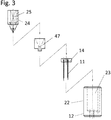
- Example 1 “Electroporation electrode having a plurality of electrode needles” As an embodiment of the electrode according to the present invention, an electrode for electroporation (1) shown in FIGS. 1 to 13 was produced. Hereinafter, the electrode for electroporation (1) manufactured in the present embodiment will be described with reference to exploded views and structural drawings.
- the electrode for electroporation includes a scarlet needle (diameter 0.26 mm, needle length 8.5 mm) made of stainless steel as the first polarity electrode needle (11), and the three electrode needles.
- a scarlet needle (diameter 0.26 mm, needle length 8.5 mm) made of stainless steel as the first polarity electrode needle (11), and the three electrode needles.
- the first polarity electrode needle (11) was inserted and fixed in a direction perpendicular to the bottom surface of the electrode needle through hole (13) formed in the bottom surface of the outer frame support lower structure (12) as a housing. It is a fixed electrode needle.
- the first polarity energization portion (14) is a substantially circular flat plate member having a thickness of about 1.5 mm and having a recessed connection portion (16) with a member constituting the first polarity electrode needle.
- a member made of stainless steel. The member is connected to a power source through wiring.
- An opening (15) for communicating with the syringe needle insertion / extraction path (40) is provided at the center of the first polarity energization section (14).
- the outer frame support lower structure (12) is a member that constitutes the outer frame body of the electrode according to the present embodiment, and is a member that is made of a polycarbonate resin that is an insulating material.
- the outer diameter of the outer frame support lower structure (12) is 10 mm as viewed from the bottom.
- the needle length of the first polar electrode needle (11) protruding from the bottom surface of the outer frame support lower structure (12) is the outer frame support lower structure. It is a fixed length of 5 mm from the bottom surface.
- the first polar electrode needles (11) are arranged at equal intervals on concentric circles in the bottom view of the outer frame support lower structure (12). Specifically, it is a structure arranged on a concentric circle having a radius of 1.5 mm (diameter 3 mm) from the center of the syringe needle insertion / extraction hole (46) which is the center of the concentric circle.
- the upper part of the outer frame support lower structure (12) is a member constituting the substantially cylindrical syringe head mounting part external structure (22) having an outer diameter of 10 mm.
- the internal structure of the portion is a structure that is hollowed out into a substantially cylindrical shape with an inner diameter of 6 mm.
- the syringe head mounting part internal structure (24) is embedded and held.
- the syringe head mounting portion internal structure (24) is a member made of stainless steel, and has a structure hollowed into a substantially cylindrical shape having an inner diameter of 4.4 mm and a height of 5.35 mm, and narrows downward.
- the structure is hollowed out into a substantially cylindrical shape having an inner diameter of 3.2 mm and a height of 1 mm.
- a syringe needle insertion hole (45) is formed at the center of the bottom surface of the internal structure (25).
- the syringe head mounting part internal structure (24) is a member connected to a power source via wiring.
- the lower side of the syringe mounting part internal structure (24) is connected and fixed to the outer frame support lower structure (12) via a spacer part (47) which is a collar.
- the spacer portion (47) is a member made of polycarbonate, which is an insulating material, and prevents the region energized in the second polarity from directly contacting the first polarity energizing portion (14). It functions as an insulating member.
- the electrode according to the present embodiment has a structure in which the syringe mounting portion internal structure (24) and the outer frame support lower structure (12) communicate with each other and a syringe needle insertion / extraction path (40) that is a tubular path structure is formed.
- a syringe needle insertion / exit flow path (40) is formed in the direction of the outer frame support lower structure (12) from the syringe needle insertion / extraction hole (45) in the bottom (26) of the syringe mounting portion internal structure.
- the syringe needle insertion / extraction flow path (40) forms a second polarity energization section (42) which is a straight pipe path having a tube length of 1.6 mm and a cross-sectional diameter of 0.5 mm.
- the spacer section (47) forms a tubular structure (43) so as to protect the outer wall, and the first polarity energization section (14) and The contact is prevented.
- the lower part of the syringe needle insertion / extraction path (40) is an insertion / extraction path (44) constituted by the base material of the outer frame support lower structure (12). A 1 mm syringe needle insertion hole (46) is formed.
- Example 2 “Electroporation electrode with syringe attached” An electrode for electroporation in which a commercially available syringe was attached to the electrode manufactured in the above example was assembled and manufactured.
- the syringe (50) attached a syringe for 0.5 mL insulin (manufactured by MyJector (registered trademark) Terumo Corporation) was used. Further, 29G (diameter 0.33 mm, needle length 13 mm) was used as the syringe needle (52).
- the needle length of the syringe needle (52) which is the second polar electrode needle protruding from the syringe needle insertion / extraction hole (46) of the outer frame support lower structure (12) is The fixed length was 4 mm from the bottom surface of the frame support lower structure (12). This was the needle length that was 1 mm shorter than the fixed length of 5 mm of the first polarity electrode needle (11).
- FIG. 13B shows a photographic image of the syringe-mounted electrode manufactured in this example.
- the syringe mounting can be executed only by a simple assembling operation for inserting a syringe needle.
- this electrode it is possible to apply a voltage with the first polarity and the second polarity as any one of + and ⁇ .
- Example 3 “Example of gene introduction into muscle tissue” A gene introduction test using an electrode for electroporation having an electrode needle produced in the above example was performed on muscle tissue.
- the operability of electroporation in vivo is dramatically improved, and it is also good for skeletal muscle that tends to have low introduction efficiency. It has been demonstrated that gene transfer is easily possible. Moreover, since the mounted syringe is a commercially available disposable syringe, sample filling is easy, and electroporation with reduced risk of contamination and infection was possible.
- the present invention is expected to be used in life science fields such as molecular biology, genetic engineering, and cell biology, medical fields such as medicine and drug discovery, and livestock fields such as livestock and poultry. In particular, it is expected to be effectively used in the technical field using electroporation in vivo.
- Electrode needle holder 11. First polarity electrode needle 12. Outer frame support lower structure 13. Electrode needle through hole 14. First polarity energization section 15. Opening 16. Connection unit 17. Wiring, cable 18. Wiring holder
- Syringe needle insertion path 41 Syringe needle insertion path (syringe head mounting part side) 42. Second polarity energization section 43. Syringe needle insertion path (spacer) 44. Syringe needle insertion path (outer frame support lower structure side) 45. Syringe needle insertion hole (Syringe head mounting part side) 46. Syringe needle insertion hole (outer frame support lower structure side) 47. Spacer part
Abstract
Description
ここで、一般的な針型電極を用いて筋肉組織や皮膚組織等に対してin vivoエレクトロポレーションを行う操作手順としては、i )対象組織に導入物質を含む溶液を注射し、ii)注射部にマジック等で印をつけ、iii)注射針を抜き、iv)針型電極を用いて、電極針を刺す深度を調整し、v )電気パルスを対象組織に与える等の一連の操作を正確且つ迅速に行う方法が挙げられる。しかし、当該従来法においては、注射部のマーキング及び深度調整等の操作に熟練が求められ、また仮に熟練度の高い者であったとしても実験結果にばらつきが生じやすいという問題がある。また、上記溶液注射から電気パルスを与えるまでに数十秒~数分のタイムラグが生じるため、注入した導入物質が組織内の血流にて拡散してしまうという原理的な課題がある。 The main reason for the low efficiency of electroporation for introduction into muscular tissue, skin tissue, etc. by the in vivo method is that the experimenter or engineer needs to learn advanced handling techniques.
Here, as an operation procedure for performing in vivo electroporation on muscle tissue, skin tissue or the like using a general needle-type electrode, i) injection of a solution containing the introduced substance into the target tissue, and ii) injection Mark the area with a magic, etc., iii) remove the injection needle, iv) adjust the depth of needle insertion using the needle-type electrode, and v) accurately perform a series of operations such as applying an electrical pulse to the target tissue In addition, there is a method of performing it quickly. However, in the conventional method, there is a problem that skill is required for operations such as marking of the injection portion and depth adjustment, and even if the person has a high skill level, the experiment results are likely to vary. In addition, since there is a time lag of several tens of seconds to several minutes from the injection of the solution to the application of an electric pulse, there is a principle problem that the injected introduced substance diffuses in the blood flow in the tissue.
従って、特許文献2に記載の装置の電極アレイを用いた場合、研究現場や治療現場等において安定して簡便に使用可能な構造を備えた装置とは認められない。この点、特許文献2に記載の装置は他の従来技術には見られなかった新たな技術的課題を内在する装置である。 In addition, a therapeutic electrode device in which one or more electrodes of an electrode array including a plurality of electrode needles are cannulated is disclosed (Patent Document 2). However, the part which comprises the electrode array in patent document 2 is a part of part of the electric device for handheld treatment, and a cannulated needle is only a part of an integrated structure with other electrode needles. Specifically, the electrode device described in Patent Document 2 is a device in which a multi-electrode needle and an electrode system, a cannula needle and a liquid supply pipe system, a control system, and the like are completely integrated. It is recognized that the needle and the liquid supply pipe attached to the needle need to be replaced, and there are problems in the speed and simplicity of device assembly and sample filling in the pre-experiment preparation. In addition, if a member dedicated to the apparatus of the liquid supply system such as a pipe member is reused, there are concerns about problems such as contamination and infection.
Therefore, when the electrode array of the device described in Patent Document 2 is used, the device cannot be recognized as a device having a structure that can be used stably and simply at a research site or a treatment site. In this regard, the device described in Patent Document 2 is a device that has a new technical problem that has not been found in other prior arts.
詳しくは、前記電極針保持部が、外枠支持体下部構造体及び第1極性用通電部を含んでなる構造体であって、前記外枠支持体下部構造体の底面から第1極性電極針がエレクトロポレーション対象物側に2本以上突出した構造を有し、前記外枠支持体下部構造体の底面にシリンジ保持部側と連通するシリンジ針挿入出孔を有する部材構成に着想した。
また、前記エレクトロポレーション用電極が、前記電極針保持部のエレクトロポレーション対象物側とは反対側にシリンジ針を挿入してシリンジ装着可能なシリンジ保持部を備えた構造であって、前記シリンジ保持部が導電性材質で構成されてなる第2極性用通電部を少なくとも一部に備えたシリンジ針挿入出路を有する構造である部材構成に着想した。 In the state of the prior art described above, the present inventors have intensively studied, and as a result, have conceived the technology using the structure including the first polarity electrode needle, the electrode needle holding portion, and the syringe holding portion as a member electrode. Invented the invention.
Specifically, the electrode needle holding part is a structure including an outer frame support lower structure and a first polarity energization part, and the first polarity electrode needle is formed from the bottom surface of the outer frame support lower structure. Has a structure in which two or more projecting toward the electroporation object side and a syringe needle insertion / exit hole communicating with the syringe holding part side on the bottom surface of the outer frame support lower structure.
The electrode for electroporation includes a syringe holding portion on which a syringe needle can be inserted by inserting a syringe needle on the opposite side of the electrode needle holding portion from the electroporation object side, and the syringe It was conceived of a member configuration that is a structure having a syringe needle insertion / extraction path provided with at least a part of the second polarity energization part, in which the holding part is made of a conductive material.
これにより本発明者らは、当該エレクトロポレーション用電極を用いることによって、操作者の熟練度に依存することなく外来物質を含む溶液の注射及び電圧印加までの一連の操作を極めて短時間で安定して実行可能となることを見出した。これにより本発明者らは、in vivo法によるエレクトロポレーションの導入効率を向上できることを見出した。当該電極構造体を用いた方法においては、試料充填操作がシリンジ装着のみで可能となるため、電極装置の組立や試料注入等の準備操作を含めて迅速且つ簡便に行うことが可能であった。また、試料交換もシリンジ交換によって簡便に可能であるためコンタミネーション及び感染リスクが低減されたものであった。 The present inventors use the attached syringe needle as the second polarity electrode needle by attaching the existing syringe provided with the syringe needle to the syringe holding portion of the electrode structure having the plurality of first polarity electrode needles. I found it possible. That is, the present inventors have conceived the idea of a member electrode having a structure that allows an existing disposable syringe to be attached and detached, and produced an electrode structure. And the effect was demonstrated by gene introduction experiment.
As a result, by using the electroporation electrode, the present inventors can stabilize a series of operations up to injection of a solution containing a foreign substance and voltage application in a very short time without depending on the skill level of the operator. And found that it was feasible. As a result, the present inventors have found that the introduction efficiency of electroporation by an in vivo method can be improved. In the method using the electrode structure, since the sample filling operation can be performed only by mounting the syringe, it is possible to perform the operation quickly and easily including preparation operations such as assembly of the electrode device and sample injection. Moreover, since sample exchange can be easily performed by syringe exchange, contamination and the risk of infection were reduced.
[項1]
複数の電極針を有するエレクトロポレーション用電極であって、
(A)第1極性電極針、電極針保持部、及びシリンジ保持部を含んでなる構造を有し、
(B)前記電極針保持部が、外枠支持体下部構造体及び第1極性用通電部を含んでなる構造体であって、前記外枠支持体下部構造体の底面にシリンジ保持部側と連通するシリンジ針挿入出孔を有し、
(C)前記外枠支持体下部構造体の底面から第1極性電極針がエレクトロポレーション対象物側に2本以上突出した構造を有し、
(D)(d-1)前記エレクトロポレーション用電極が、前記電極針保持部のエレクトロポレーション対象物側とは反対側に、シリンジ針を挿入してシリンジ装着可能なシリンジ保持部を備えた構造であって、(d-2)前記シリンジ保持部が、導電性材質で構成されてなる第2極性用通電部を少なくとも一部に備えたシリンジ針挿入出路を有する構造である、
ことを特徴とするエレクトロポレーション用電極。
[項2]
前記エレクトロポレーション用電極が、前記シリンジ保持部にシリンジを装着した際に、第2極性用通電部との接触を介してシリンジ針挿入出孔から突出したシリンジ針を第2極性電極針として使用可能とする部材電極である、項1に記載のエレクトロポレーション用電極。
[項3]
前記第1極性電極針が、
外枠支持体下部構造体の底面視にて第1極性電極針の先端を結ぶ直線上若しくは略直線上又は第1極性電極針の先端を頂点として形成される多角形の内側にシリンジ針挿入出孔が位置するように、配置されたものである、
項1又は2のいずれかに記載のエレクトロポレーション用電極。
[項4]
前記シリンジ針挿入出路における第2極性用通電部の少なくとも一部が、導電性物質からなる直管構造を有する構造であって、シリンジ針挿入時にシリンジ針との接触が担保される内径又は内幅を有するものである、項1~3のいずれかに記載のエレクトロポレーション用電極。
[項5]
前記第1極性電極針が、電極針保持部の外枠支持体下部構造体を貫通して第1極性用通電部に接続された構造を有する、項1~4のいずれかに記載のエレクトロポレーション用電極。
[項6]
前記エレクトロポレーション用電極が、
(E)(e-1)前記第1極性電極針が、第1極性用通電部との接続部にて着脱可能な構造を有する、又は、(e-2)前記第1極性用通電部が分離可能な接続部を備えた構造を有する、ことによって前記外枠支持体下部構造体の一部又は全部と伴に前記第1極性電極針の着脱を可能とするものである、
項1~5のいずれかに記載のエレクトロポレーション用電極。
[項7]
前記1極性電極針が突出する角度が、外枠支持体下部構造体の底面に対して垂直及び/又は略垂直方向である、項1~6のいずれかに記載のエレクトロポレーション用電極。
[項8]
前記第1極性電極針の本数が3本以上である、項1~7のいずれかに記載のエレクトロポレーション用電極。
[項9]
前記第1極性電極針が、外枠支持体下部構造体の底面視にてシリンジ針挿入出孔の中心から0.5~10mmの範囲に配置されたものである、項1~8のいずれかに記載のエレクトロポレーション用電極。
[項10]
前記第1極性電極針が、外枠支持体下部構造体の底面視にてシリンジ針挿入出孔を中心とする同心円上又は略同心円上に等間隔又は略等間隔に配置されたものである、項1~9のいずれかに記載のエレクトロポレーション用電極。
[項11]
前記第1極性電極針が、電極針保持部における外枠支持体下部構造体の底面から突出した電極長にて1~10mmの固定電極針である、項1~10のいずれかに記載のエレクトロポレーション用電極。
[項12]
項1~11のいずれかに記載のエレクトロポレーション用電極のシリンジ保持部にシリンジを装着してシリンジ針挿入出孔からシリンジ針が突出した構造を有し、第2極性用通電部との接触を介して当該突出したシリンジ針が第2極性電極針として機能することを特徴とする、エレクトロポレーション用電極。
[項13]
前記第2極性電極針となったシリンジ針が、シリンジ針挿入出孔から突出した針長において、外枠支持体下部構造体の底面から突出した第1極性電極針の平均針長と比較して-4~+2mmの範囲である、項12に記載のエレクトロポレーション用電極。
[項14]
前記第1極性電極針、前記電極針保持部、及び前記シリンジ保持部を構成する部材を含んでなる、項1~13のいずれかに記載のエレクトロポレーション用電極の組立用キット。 The present invention specifically relates to the invention described below.
[Claim 1]
An electroporation electrode having a plurality of electrode needles,
(A) having a structure including a first polarity electrode needle, an electrode needle holding portion, and a syringe holding portion;
(B) The electrode needle holding portion is a structure including an outer frame support lower structure and a first polarity energization portion, and a syringe holding portion side on the bottom surface of the outer frame support lower structure; It has a syringe needle insertion hole that communicates,
(C) It has a structure in which two or more first polar electrode needles protrude from the bottom surface of the outer frame support lower structure toward the electroporation object side,
(D) (d-1) The electrode for electroporation includes a syringe holding portion on the side opposite to the electroporation object side of the electrode needle holding portion so that a syringe needle can be inserted and attached to the syringe. (D-2) The syringe holding part is a structure having a syringe needle insertion / extraction path provided at least in part with a second polarity energization part made of a conductive material.
An electrode for electroporation characterized by the above.
[Section 2]
When the electroporation electrode is mounted on the syringe holding part, the syringe needle protruding from the syringe needle insertion / extraction hole through contact with the second polarity energization part is used as the second polarity electrode needle. Item 2. The electrode for electroporation according to
[Section 3]
The first polarity electrode needle is
Syringe needle insertion / extraction on a straight line or a substantially straight line connecting the tips of the first polarity electrode needles or a polygon formed with the tips of the first polarity electrode needles as apexes in the bottom view of the outer frame support lower structure It is arranged so that the hole is located,
Item 3. The electrode for electroporation according to any one of
[Claim 4]
At least a part of the second polarity energization part in the syringe needle insertion / extraction path has a structure having a straight tube structure made of a conductive substance, and an inner diameter or an inner width that ensures contact with the syringe needle when the syringe needle is inserted. Item 4. The electrode for electroporation according to any one of
[Section 5]
Item 5. The electroporation according to any one of
[Claim 6]
The electrode for electroporation is
(E) (e-1) The first polarity electrode needle has a structure that can be attached and detached at the connection portion with the first polarity energization portion, or (e-2) the first polarity energization portion is By having a structure with a separable connection part, it is possible to attach and detach the first polar electrode needle together with a part or all of the outer frame support lower structure.
Item 6. The electrode for electroporation according to any one of
[Claim 7]
[Section 8]
Item 8. The electroporation electrode according to any one of
[Claim 9]
Any one of
[Section 10]
The first polar electrode needles are arranged on a concentric circle or a substantially concentric circle centered on the syringe needle insertion / exit hole at a bottom view of the outer frame support lower structure at regular intervals or substantially regular intervals. Item 10. The electrode for electroporation according to any one of
[Section 11]
[Claim 12]
[Claim 13]
Compared with the average needle length of the first polarity electrode needle protruding from the bottom surface of the outer frame support lower structure in the needle length that the syringe needle that has become the second polarity electrode needle protrudes from the syringe needle insertion hole.
[Section 14]
The present invention is a technique capable of stably improving the efficiency of introducing foreign substances, and enables electroporation by an in vivo method by a quick and simple operation without depending on the skill level of the operator. Technology can be provided. For example, in the present invention, it is possible to perform suitable electroporation by an in vivo method on muscle tissue, skin tissue, or the like that tends to have low introduction efficiency in the conventional method.
以下、本発明の実施形態について詳細に説明する。以下の説明における符号番号は、図面中に使用した符号番号を意味する。 This application is an application with a priority claim based on Japanese Patent Application No. 2016-030984 filed in Japan by the present applicant, the entire contents of which are incorporated into this application by reference.
Hereinafter, embodiments of the present invention will be described in detail. The code numbers in the following description mean the code numbers used in the drawings.
本明細書中、「エレクトロポレーション法」(電気穿孔法)は、細胞に電気パルスを与え、細胞膜に外来物質が通過できる小孔を一過性に作って細胞内に外来物質を取り込ませる方法である。様々な生物種及び様々な種類の組織や細胞等への適用が可能な汎用性の高い外来物質導入手法である。
本明細書中、「in vivo」とは生体内を意味する。試験管内を意味する「in vitro」に対比される用語である。
本明細書中、「外来導入物質」(以下、外来物質や導入物質等と表現する場合もある。)とは、エレクトロポレーション法により外部から細胞内へ導入するための物質を意味する。エレクトロポレーション法で導入できる物質であれば如何なる物質も含まれる。例えば、通常の状態では細胞膜を透過できない又は透過されにくい各種生理活性物質、薬剤、治療薬、核酸物質、ペプチド、及びタンパク質等が例示される。
ここで、核酸物質としては、例えば、DNA、RNA等が含まれる。DNAとしては、標的細胞内に導入したい核酸配列を備えたDNAが適宜選択され、例えば、遺伝子の全長配列(cDNA配列、ゲノム配列)、部分配列、調節領域、スペーサー領域、及び変異を加えた配列等、目的に応じて設計されたDNAが用いられるが、特にこれらに限定されるものではない。また、ウイルスDNA、プラスミドDNA、オリゴヌクレオチド(アンチセンスオリゴヌクレオチド、アプタマー)、およびペプチド核酸等も含まれる。RNAとしては、mRNA、siRNA等が含まれるが、特にこれらに限定されるものではない。 [Explanation of terms, etc.]
In this specification, the “electroporation method” (electroporation method) is a method in which an electric pulse is applied to a cell, and a small hole through which the foreign substance can pass is temporarily formed in the cell membrane to incorporate the foreign substance into the cell. It is. This is a versatile foreign substance introduction method that can be applied to various biological species and various types of tissues and cells.
In this specification, “in vivo” means in vivo. It is a term contrasted with “in vitro” meaning in vitro.
In the present specification, “exogenous introduction substance” (hereinafter sometimes referred to as a foreign substance, an introduction substance, etc.) means a substance to be introduced into cells from the outside by electroporation. Any substance that can be introduced by the electroporation method is included. For example, various physiologically active substances, drugs, therapeutic agents, nucleic acid substances, peptides, proteins, etc. that cannot or cannot easily permeate the cell membrane under normal conditions are exemplified.
Here, examples of the nucleic acid substance include DNA and RNA. As the DNA, a DNA having a nucleic acid sequence to be introduced into the target cell is appropriately selected. For example, a full-length gene sequence (cDNA sequence, genomic sequence), partial sequence, regulatory region, spacer region, and a sequence with mutations added. Although DNA designed according to the purpose is used, it is not particularly limited to these. Also included are viral DNA, plasmid DNA, oligonucleotides (antisense oligonucleotides, aptamers), peptide nucleic acids and the like. Examples of RNA include mRNA, siRNA and the like, but are not particularly limited thereto.
本明細書中、「シリンジ」とは、注射筒(53)、プランジャー(54)、及び注射針(52:シリンジ針)が組み立てられた状態の注射器全体(50)を指す用語として使用するものである。 In this specification, “first polarity” and “second polarity” refer to the polarity of the other electrode (in this case, the negative polarity) when one electrode polarity (for example, positive polarity) of the applied voltage is the first polarity. ) As the second polarity. The first polarity and the second polarity can be arbitrary charges.
In this specification, the “syringe” is used as a term indicating the entire syringe (50) in a state where the syringe barrel (53), the plunger (54), and the injection needle (52: syringe needle) are assembled. It is.
例えば、本明細書中、「略」を付した角度や方向を表す表現は、対象角度や方向に対して実質的に問題にならない程度の角度の傾きを許容するものである。
また、本明細書中、「略」を付した図形、形状、及び配列等が円等の場合であれば、円周部分がやや歪んだ形状、長円や楕円等の変形図形を許容して指すものである。また、角形等の場合であれば、対象図形に対して角が丸みを帯びた形状、外周がやや歪んだ形状等の変形図形を許容して指すものである。また、格子状等の配列状態の場合も同様に、配列構成要素が形成する図形等の変形が許容される。また、直線の場合も曲率の低い歪みや曲線を含むことが許容される。また、立体の場合についても、全体形態や断面形態において同様に定義することができる。 In the present specification, expressions representing “substantially” figures, shapes, angles, and the like refer to figures with some modifications and the like.
For example, in this specification, an expression representing an angle or direction with “substantially” allows an inclination of an angle that is not substantially problematic with respect to the target angle or direction.
In addition, in the present specification, if the figure, shape, arrangement, etc. given “substantially” is a circle or the like, a shape whose circumference is slightly distorted, a deformed figure such as an ellipse or an ellipse is allowed. It is what you point to. In the case of a square or the like, it refers to a deformed figure having a rounded corner with respect to the target figure and a shape having a slightly distorted outer periphery. Similarly, in the case of an array state such as a lattice, deformation of a figure or the like formed by the array components is allowed. Also, straight lines are allowed to contain distortions and curves with low curvature. Further, the three-dimensional case can be defined in the same manner in the overall form and the cross-sectional form.
本発明は、第1極性電極針(11)、電極針保持部(10)、及びシリンジ保持部(20)を備えた構造を有する複数の電極針を有するエレクトロポレーション用電極に関する。具体的には、複数の第1極性電極針を備えたエレクトロポレーション用電極であって、シリンジ(50)を装着状態にした場合において装着したシリンジ針(52)を第2極性電極針とすることを可能とするエレクトロポレーション用電極に関する。
本発明に係るエレクトロポレーション用電極(1)を構成する主たる部材について、その構成部材の属性を整理した表を以下に示す。なお、表1は各構成部材の属性を整理した表であり必須部材を表したものでない。この点、本発明に係る技術的範囲は表1に記載の部材を全て含む態様に限定されるものではない。 1. Electroporation electrode having a plurality of electrode needles The present invention includes a plurality of electrode needles having a structure including a first polarity electrode needle (11), an electrode needle holding part (10), and a syringe holding part (20). The present invention relates to an electrode for electroporation. Specifically, it is an electrode for electroporation having a plurality of first polarity electrode needles, and the syringe needle (52) attached when the syringe (50) is in the attached state is used as the second polarity electrode needle. The present invention relates to an electrode for electroporation that makes it possible.
The table which arranged the attribute of the structural member about the main member which comprises the electrode (1) for electroporation which concerns on this invention is shown below. In addition, Table 1 is a table in which attributes of each constituent member are arranged, and does not represent essential members. In this respect, the technical scope according to the present invention is not limited to an embodiment including all the members shown in Table 1.

本発明に係るエレクトロポレーション用電極(1)は、第1極性に関する構造として、第1極性電極針(11)及び電極針保持部(10)等を備えて構成される電極である。なお、第1極性に関する構造としては、電源と接続するための配線、導線、及び/又は電源ケーブル等、外枠支持体の強度を高めるための支持部材等を含める構造とすることも可能である。 [Structure for first polarity]
The electrode (1) for electroporation according to the present invention is an electrode comprising a first polarity electrode needle (11), an electrode needle holding portion (10) and the like as a structure relating to the first polarity. In addition, as a structure regarding the first polarity, a structure including a support member for increasing the strength of the outer frame support body, such as a wiring for connecting to a power source, a conductive wire, and / or a power cable can be used. .
本発明に係るエレクトロポレーション用電極(1)は、電極針保持部を構成する外枠支持体下部構造体(12)の底面から、第1極性電極針(11)がエレクトロポレーション対象物側に突出した構造を有する電極である。 [First polarity electrode needle]
In the electrode for electroporation (1) according to the present invention, the first polar electrode needle (11) is disposed on the electroporation object side from the bottom surface of the outer frame support lower structure (12) constituting the electrode needle holding portion. It is an electrode which has the structure which protruded.
第1極性電極針は導電性を有する材質で構成されていることが好適である。第1極性電極針(11)を構成する材質としては、通常の電極として使用可能な材質であれば良い。例えば、ステンレス鋼、白金、鉄鋼、銅、鉄、チタン合金、アルミニウム合金、カーボン等の材質のものが好適である。
第1極性電極針(11)を構成する材質として特には、錆びにくく且つ生体への影響が懸念されない金属性の材質が好適である。例えば、ステンレス鋼、白金、チタン合金等の材質のものが好適である。
また、第1極性電極針(11)としては、先端が鋭利で対象の生体組織への穿孔に適した針状又は針型の形状であれば如何なる形状であっても良い。先端が鋭利であれば、屈曲形状や湾曲形状等の角度や曲率を有する形状も許容される。
また、第1極性電極針(11)としては、分岐形状、先端方向に向かって複数針に分岐した形状、先端方向に向かって複数針が合流した形状、等を採用することができる。また、外枠支持体下部構造体(12)の底面から突出した電極針の根元側が絶縁部材で被覆された構造を採用することができる。また、外枠支持体下部構造体(12)の底面から突出した根元側が、外枠支持体下部構造体の底面方向と水平又は浅い角度にて配置される平面、略平面、環状等の構造を有し、当該構造部分から1又は2以上の針状又は針型の形状が突出した構造のものを採用することができる。
第1極性電極針(11)の形状として好ましくは、鋭利な直棒状又は直管状の針形状を含む形状を挙げることができる。より好ましくは、医療や鍼灸等で使用される鋭利な直棒状又は直管状の形状を挙げることができる。例えば、スカーレット針形状、中空針形状、注射針形状、鍼形状、鋭角円錐形状等の針を挙げることができる。当該針の横断面としては円状、略円状、長円状、楕円状、環状、角環状等を挙げることができるが、特に円状又は略円状等であることが好ましい。
また、第1極性電極針(11)の横断面の外径としては、生体組織への穿孔に適した径であれば良く、例えば0.5mm以下、好ましくは0.4mm以下、より好ましくは0.35mm以下、更に好ましくは0.33mm以下、特に好ましくは0.30mm以下、一層好ましくは0.28mm以下、より一層好ましくは0.26mm以下を挙げることができる。下限としては針強度が確保できる限りは特に制限はないが、例えば0.1mm以上、好ましくは0.15mm以上を挙げることができる。 In the present specification, the “first polarity electrode needle” (11) means a needle-like electrode indicating one electrode polarity of an applied voltage.
It is preferable that the first polarity electrode needle is made of a conductive material. The material constituting the first polarity electrode needle (11) may be any material that can be used as a normal electrode. For example, materials of stainless steel, platinum, steel, copper, iron, titanium alloy, aluminum alloy, carbon and the like are suitable.
In particular, a metallic material that is not easily rusted and does not have a concern about the influence on the living body is preferable as the material constituting the first polarity electrode needle (11). For example, a material such as stainless steel, platinum, titanium alloy or the like is suitable.
Further, the first polarity electrode needle (11) may have any shape as long as the tip is sharp and has a needle shape or a needle shape suitable for perforating a target biological tissue. If the tip is sharp, a shape having an angle or curvature such as a bent shape or a curved shape is allowed.
Further, as the first polarity electrode needle (11), a branched shape, a shape branched into a plurality of needles in the distal direction, a shape in which a plurality of needles merged in the distal direction, and the like can be adopted. Moreover, the structure by which the base side of the electrode needle protruded from the bottom face of the outer frame support lower structure (12) is covered with an insulating member can be adopted. In addition, the base side protruding from the bottom surface of the outer frame support lower structure (12) has a structure such as a plane, a substantially flat surface, an annular shape, etc. arranged at a horizontal or shallow angle with the bottom surface direction of the outer frame support lower structure. And having a structure in which one or two or more needle-shaped or needle-shaped shapes protrude from the structure portion can be employed.
The shape of the first polar electrode needle (11) is preferably a shape including a sharp straight bar shape or a straight tubular needle shape. More preferably, a sharp straight bar shape or a straight tubular shape used in medical treatment or acupuncture can be used. Examples of the needle include a scarlet needle shape, a hollow needle shape, an injection needle shape, a heel shape, and an acute angle cone shape. Examples of the cross section of the needle include a circular shape, a substantially circular shape, an oval shape, an elliptical shape, a circular shape, and a rectangular shape, and a circular shape or a substantially circular shape is particularly preferable.
Further, the outer diameter of the cross section of the first polar electrode needle (11) may be any diameter suitable for perforating a living tissue, for example, 0.5 mm or less, preferably 0.4 mm or less, more preferably 0. .35 mm or less, more preferably 0.33 mm or less, particularly preferably 0.30 mm or less, more preferably 0.28 mm or less, and still more preferably 0.26 mm or less. The lower limit is not particularly limited as long as the needle strength can be ensured, and examples thereof include 0.1 mm or more, preferably 0.15 mm or more.
ここで、本発明においても、第1極性電極針の長さを自在に調整可能とする機構を設けた電極とすることも可能ではある。しかし、本発明が解決すべき課題の1つとして、簡便な操作性の提供等が挙げられ、更に製造効率等を考慮すると、第1極性電極針は固定電極針とする態様が好適である。 In the electrode for electroporation (1) according to the present invention, an embodiment in which the first polarity electrode needle (11) is a fixed electrode needle is preferable.
Here, also in the present invention, an electrode provided with a mechanism that allows the length of the first polarity electrode needle to be freely adjusted is also possible. However, as one of the problems to be solved by the present invention, provision of simple operability and the like can be mentioned, and in consideration of manufacturing efficiency and the like, it is preferable that the first polar electrode needle is a fixed electrode needle.
また、各第1極性電極針間の電極長の差異としては、電極針保持部の外枠支持体下部構造体(12)の底面から突出した第1極性電極針の平均針長と比較して-2~+2mmの範囲、好ましく-1~+1mmの範囲、より好ましくは-0.5~+0.5mmの範囲、更に好ましくは-0.2~+0.2mmの範囲であることが好適である。最も好ましくは、電極針保持部の外枠支持体下部構造体(12)の底面から突出した第1極性電極針の全てが同一の針長であることが最適である。
なお、ここで、第1極性電極針(11)の基部部分については、電極針保持部の外枠支持体下部構造体(12)内に埋設された状態となり上記針長には考慮されない。そのため、当該埋設される基部部分の針長については特に制限はなく採用可能である。
また、第1極性電極針(11)の電極針長としては、底面から突出した部分のうちの直棒状又は直管状の部分の電極長を表す長さであることが好適である。 The electrode needle length of the first polarity electrode needle (11) is 1 mm or longer, preferably 2 mm or longer, more preferably 2 mm or longer, with the electrode length protruding from the bottom surface of the outer frame support lower structure (12) of the electrode needle holder. It is suitable that it is 3 mm or more, more preferably 4 mm or more. The upper limit is preferably 10 mm or less, preferably 8 mm or less, more preferably 6 mm or less, and still more preferably 5 mm or less. That is, 1 to 10 mm, preferably 2 to 8 mm, more preferably 3 to 6 mm, and still more preferably 4 to 5 mm.
Further, the difference in electrode length between the first polar electrode needles is compared with the average needle length of the first polar electrode needles protruding from the bottom surface of the outer frame support lower structure (12) of the electrode needle holding portion. A range of -2 to +2 mm, preferably a range of -1 to +1 mm, more preferably a range of -0.5 to +0.5 mm, and still more preferably a range of -0.2 to +0.2 mm. Most preferably, it is optimal that all of the first polar electrode needles protruding from the bottom surface of the outer frame support lower structure (12) of the electrode needle holding part have the same needle length.
Here, the base portion of the first polarity electrode needle (11) is embedded in the outer frame support lower structure (12) of the electrode needle holding portion and is not considered in the needle length. Therefore, the needle length of the embedded base portion is not particularly limited and can be employed.
Further, the electrode needle length of the first polar electrode needle (11) is preferably a length representing the electrode length of a straight rod-like or straight tubular portion of the portion protruding from the bottom surface.
従って、本発明に係るエレクトロポレーション用電極は、電極針を根本まで押し込むという簡便な操作によって、エレクトロポレーションに適切な深度への電極針の挿針が可能となる。 The electrode (1) for electroporation according to the present invention has a structure including a fixed electrode needle having the above-mentioned predetermined electrode needle length, so that complicated operations such as depth adjustment are performed when the needle is inserted into muscle or skin. Is no longer necessary. Here, the fixed electrode needle length within the range of the electrode length can realize an appropriate depth when electroporation is performed on muscles, skin, or the like.
Therefore, the electrode for electroporation according to the present invention can be inserted into a depth appropriate for electroporation by a simple operation of pushing the electrode needle to the root.
また、第1極性電極針(11)の配置される位置としては、電極針保持部の外枠支持体下部構造体(12)の底面視にて、シリンジ針挿入出孔(46)の中心から0.5~10mmの範囲、好ましくは0.5~5mmの範囲、より好ましくは0.75~4mmの範囲、更に好ましくは1~3mmの範囲、特に好ましくは1~2mmの範囲に配置されたものであることが好適である。当該範囲としては、好ましくは底面視での電極針先端とシリンジ針挿入出孔との距離を表す範囲であることが好適である。
第1極性電極針の間の距離が上記範囲にある場合、低い電圧を印加した場合であっても単位cmあたりの電場強度(V/cm)を高く与えることが可能となり、組織や細胞へのダメージ及び損傷が低減できて好適である。なお、上記範囲より広すぎる場合、必要な電場強度を与えるための印加電圧に高電圧が必要となり好適でない。また、上記範囲より狭すぎる場合、エレクトロポレーション範囲の適用領域が狭すぎて十分な領域の遺伝子導入が実現しにくくなり好適でない。 In the electrode for electroporation (1) according to the present invention, the first polarity electrode needle (11) is disposed at the first polarity electrode needle (11) in the bottom view of the outer frame support lower structure (12). ) Is arranged so that the syringe needle insertion hole (46) is located on a straight line or a substantially straight line connecting the tips of the needles) or inside a polygon formed with the tip of the first polarity electrode needle (11) as a vertex. It is suitable. Further, the bottom of the outer frame support lower structure (12) is a straight line or a substantially straight line connecting the bases of the first polar electrode needles (11) or the base of the first polar electrode needles (11) as a vertex. It is also preferable that the syringe needle insertion / exit hole (46) is positioned inside the formed polygon.
Further, the position where the first polarity electrode needle (11) is arranged is from the center of the syringe needle insertion / extraction hole (46) in the bottom view of the outer frame support lower structure (12) of the electrode needle holding portion. Arranged in the range of 0.5 to 10 mm, preferably in the range of 0.5 to 5 mm, more preferably in the range of 0.75 to 4 mm, still more preferably in the range of 1 to 3 mm, and particularly preferably in the range of 1 to 2 mm. It is suitable. The range is preferably a range that represents the distance between the tip of the electrode needle and the syringe needle insertion / extraction hole in a bottom view.
When the distance between the first polar electrode needles is in the above range, it is possible to give a high electric field strength (V / cm) per unit cm even when a low voltage is applied. It is preferable because damage and damage can be reduced. In addition, when too wider than the said range, a high voltage is needed for the applied voltage for giving required electric field strength, and it is not suitable. Moreover, when it is too narrow than the said range, the application area | region of an electroporation range is too narrow and it becomes difficult to implement | achieve gene introduction | transduction of sufficient area | region, and is not suitable.
具体的には、電極針を構成する針数が2本の場合には、電極針保持部の外枠支持体下部構造体(12)の底面視にて、シリンジ針挿入出孔(46)の中心から対角線上又は略対角線上に等距離又は略等距離となるように配置することが好適である。また、電極針を構成する針数が3本以上の場合は、電極針保持部の外枠支持体下部構造体(12)の底面視にて、第1極性電極針(11)を頂点として形成される多角形が正多角形又は略正多角形となる位置であることが好適である。なお、当該位置としては、好ましくは底面視での電極針先端とシリンジ針挿入出孔との位置を表すものであることが好適である。
本発明に係るエレクトロポレーション用電極(1)においては、第1極性電極針(11)と第2極性電極針であるシリンジ針(52)(又はシリンジ針挿入出孔(46))との各間隔が等距離に近い程、均一な電場を発生されることが可能となり好適である。また、本発明に係るエレクトロポレーション用電極(1)においては、第1極性電極針(11)間の各間隔が等距離に近い程、均一な電場発生が可能となり好適である。 The position where the first polarity electrode needle (11) is arranged is a concentric circle centering on the syringe needle insertion hole (46) in the bottom view of the outer frame support lower structure (12) of the electrode needle holder. It is preferable that they are arranged on top or substantially concentric circles. Moreover, as a position where the 1st polarity electrode needle | hook (11) is arrange | positioned, it is suitable to arrange | position so that between each electrode may become equal intervals or substantially equal intervals.
Specifically, when the number of needles constituting the electrode needle is two, the syringe needle insertion hole (46) is viewed from the bottom of the outer frame support lower structure (12) of the electrode needle holder. It is preferable to arrange them so that they are equidistant or substantially equidistant from the center diagonally or approximately diagonally. When the number of needles constituting the electrode needle is three or more, the first polar electrode needle (11) is formed as the apex in the bottom view of the outer frame support lower structure (12) of the electrode needle holding portion. It is preferable that the polygon to be formed is a position that becomes a regular polygon or a substantially regular polygon. The position preferably represents the position of the tip of the electrode needle and the syringe needle insertion / exit hole in a bottom view.
In the electrode (1) for electroporation according to the present invention, each of the first polar electrode needle (11) and the syringe needle (52) (or the syringe needle insertion / exit hole (46)) as the second polar electrode needle. The closer the distance is to the equal distance, the more preferable it is that a uniform electric field can be generated. Moreover, in the electrode (1) for electroporation according to the present invention, it is preferable that each electric field between the first polar electrode needles (11) is closer to the equidistant, so that a uniform electric field can be generated.
第1極性電極針(11)として適切な本数としては2~8本、好ましくは3~7本、より好ましくは3~6本、更に好ましくは3~5本、特に好ましくは3~4本である。ここで、第1極性電極針(11)の本数としては、原則的には本数が多い程エレクトロポレーションの面積を広く取ることができ好適である。しかし、一定本数以上より電極本数を多くした場合、電極本数増設による効果よりも製造効率やコストの点が大きくなり、更に被験者や対象検体に対して多少の痛みを与える恐れがあり逆に好適でない。 In the electroporation electrode (1) according to the present invention, the number of the first polar electrode needles (11) protruding from the bottom surface of the outer frame support lower structure (12) can be two or more. However, it is more preferable that the number is 3 or more. Here, when three or more first polar electrode needles (11) are arranged, it becomes possible to generate an electric field within the polygonal area with the first polar electrode needle (11) as a vertex, and electroporation can be performed. The region that can be performed is preferably raised.
A suitable number of the first polar electrode needle (11) is 2 to 8, preferably 3 to 7, more preferably 3 to 6, further preferably 3 to 5, particularly preferably 3 to 4. is there. Here, as the number of the first polar electrode needles (11), in principle, the larger the number, the larger the area of electroporation is preferable. However, when the number of electrodes is increased from a certain number or more, the manufacturing efficiency and cost are greater than the effect of increasing the number of electrodes, and there is a risk of giving some pain to the subject and the target sample, which is not suitable. .
最も好ましくは外枠支持体下部構造体の底面に対して垂直になるように配置され固定されたものが好適である。
また、第1極性電極針(11)の形状として、底面から突出した部分が角度を有する形状である場合には、先端部分での直棒状又は直管状の部分の角度について、上記範囲の角度を採用することが好適である。 The angle at which the first polarity electrode needle (11) protrudes from the bottom surface of the outer frame support lower structure (12) of the electrode needle holder is perpendicular to the bottom surface of the outer frame support lower structure and / or substantially the same. Those arranged and fixed so as to be vertical are preferable. Here, “substantially perpendicular” refers to an angle in the range of 90 ± 10 °, preferably 90 ± 5 °, more preferably 90 ± 2 ° with respect to the bottom surface of the outer frame support lower structure (12). Is preferred. In addition, when the protrusion angle of the 1st polarity electrode needle (11) is not an angle of an appropriate range, the insertion and extraction of a needle | hook to a biological tissue are prevented, and it becomes difficult to become a suitable aspect.
Most preferably, it is arranged and fixed so as to be perpendicular to the bottom surface of the outer frame support lower structure.
Further, as the shape of the first polar electrode needle (11), when the portion protruding from the bottom surface has an angle, the angle within the above range is set for the angle of the straight rod-like or straight tubular portion at the tip portion. It is preferable to adopt.
本発明に係るエレクトロポレーション用電極(1)は、第1極性電極針(11)を物理的に保持し、第1極性電極針(11)に電圧を印加するための構造又は手段を備えた電極針保持部(10)を有する。本発明では電極針保持部(10)の構造によって、電極配置構造等の物理的形状が保持され且つ電極への電圧印加等の機能を発揮させることが可能となる。ここで、電極針保持部(10)は、以下に示す外枠支持体下部構造体(12)及び第1極性用通電部(14)を含んで構成されてなる部材である。 [Electrode needle holder]
The electrode for electroporation (1) according to the present invention includes a structure or means for physically holding the first polarity electrode needle (11) and applying a voltage to the first polarity electrode needle (11). It has an electrode needle holder (10). In the present invention, the structure of the electrode needle holding portion (10) allows the physical shape such as the electrode arrangement structure to be held, and functions such as voltage application to the electrodes to be exhibited. Here, the electrode needle holding portion (10) is a member configured to include an outer frame support lower structure (12) and a first polarity energization portion (14) shown below.
電極針保持部(10)を構成する部材としては、第1極性電極針(11)を保持するための外枠支持体下部構造体(12:実施例に係るハウジングの下部構造部分)を含むものである。ここで、外枠支持体下部構造体(12)は、第1極性電極針(11)を固定するための構造及び機能を備えた筐体様の部材である。ここで「下部」とは、本発明に係る電極(1)の全体構造において下部分を意味し、本発明に係る電極(1)に外枠支持体上部構造体が存在しない電極形態においても当て嵌まる概念である。 As a member constituting the outer frame support lower structure electrode needle holding portion (10), an outer frame support lower structure (12: housing of the embodiment) for holding the first polarity electrode needle (11) is used. Lower structure portion). Here, the outer frame support lower structure (12) is a case-like member having a structure and a function for fixing the first polarity electrode needle (11). Here, the “lower part” means the lower part in the overall structure of the electrode (1) according to the present invention, and is applicable even in the electrode configuration in which the outer frame support upper structure does not exist in the electrode (1) according to the present invention. It is a whole concept.
外枠支持体下部構造体(12)の底面形状としては、エレクトロポレーション時の電圧を対象に均一に印加することを踏まえると、平面状のものが最も好適である。 The outer frame support lower structure (12) has a shape having a bottom surface on the electroporation side. Here, as the shape of the bottom surface of the outer frame support lower structure (12), a flat plane or a substantially planar shape is suitable, but various variations such as a curved shape and a three-dimensional shape are adopted. It is also possible to do. For example, a dome shape, a cone shape, a pyramid shape, a truncated cone shape, a truncated pyramid shape, a rectangular shape, a polygonal column shape, a staircase pyramid shape, or the like may be employed. Moreover, it is also possible to employ | adopt these substantially shapes. Not only a convex shape but also a concave shape is allowed on the electroporation side. However, when a three-dimensional bottom is adopted, it is preferable that the curvature and the gradient are gentle.
The shape of the bottom surface of the outer frame support lower structure (12) is most preferably a planar shape considering that the voltage during electroporation is uniformly applied to the target.
当該形状としては特に制限はないが、シリンジ保持部(20)との連続又は接続形状である点を考慮すると、好ましくは断面形状が円状又は略円状であることが好適である。 The overall shape of the outer frame support lower structure (12) is preferably a structure having a certain thickness for physically holding the first polar electrode needle having the bottom shape. is there. Moreover, it is preferable that it is a container shape provided with the upper part or inner space for connecting and fixing the 1st polarity electricity supply part to upper part preferably. For example, a box shape, a cylindrical shape, or the like is preferable.
Although there is no restriction | limiting in particular as the said shape, Considering the point which is a continuous or connected shape with a syringe holding | maintenance part (20), It is preferable that a cross-sectional shape is preferably circular or substantially circular shape.
シリンジ針挿入出孔(46)としては、シリンジ針(52)の挿入出をスムースに行うことに適した孔であれば良いが、例えば内径又は内幅が0.1~4mm、好ましくは0.3~3mm、より好ましくは0.4~2mm、更に好ましくは0.5~1.5mm程度の孔を採用することができる。
第1極性電極針貫通孔(13)とシリンジ針挿入出孔(46)の形成位置としては、第1極性電極針(11)が上記段落に記載の配置となるように形成させることが好適である。即ち、外枠支持体下部構造体(12)の底面に、第1極性電極針貫通孔(13)を結ぶ直線上若しくは略直線上又は第1極性電極針貫通孔(13)を頂点として形成される多角形の内側に、シリンジ保持部側と連通するシリンジ針挿入出孔(46)を有す構造であることが好適である。 The outer frame support lower structure (12) has a first polarity electrode needle through hole (13) for mounting and fixing the first polarity electrode needle (11) and a second polarity electrode needle. It is preferable that the shape is provided with a syringe needle insertion / extraction hole (46) that enables insertion and extraction of the syringe needle (52).
The syringe needle insertion / extraction hole (46) may be any hole suitable for smooth insertion / extraction of the syringe needle (52). For example, the inner diameter or inner width is 0.1 to 4 mm, preferably 0. A hole having a diameter of about 3 to 3 mm, more preferably about 0.4 to 2 mm, and still more preferably about 0.5 to 1.5 mm can be employed.
As the formation position of the first polarity electrode needle through hole (13) and the syringe needle insertion / extraction hole (46), it is preferable that the first polarity electrode needle (11) is formed so as to have the arrangement described in the above paragraph. is there. That is, it is formed on the bottom surface of the outer frame support lower structure (12) on the straight line or the substantially straight line connecting the first polar electrode needle through holes (13) or with the first polar electrode needle through hole (13) as a vertex. It is preferable that the structure has a syringe needle insertion / extraction hole (46) communicating with the syringe holding part side inside the polygon.
絶縁性材質としては、硬度及び耐久性を有する材質であれば良く、例えば、樹脂、ガラス、鉱石等の材質を挙げることができる。好ましくは、ポリスチレン、ポリエチレンテレフタラート(PET)、ポリプロピレン、ポリカーボネート、ポリメチルメタクリル、ポリメチルペンテン、ABS樹脂、アクリル樹脂、フッ化炭素樹脂(PTFE、PFA、FEPなど)、ポリエーテルエーテルケトン樹脂(PEEK)、ポリイミド樹脂、セラミック(アルミナ、窒化アルミ等)等の材質を挙げることができる。 The outer frame support lower structure (12) is preferably composed of an insulating member or an insulating material. As the outer frame support lower structure (12), the first polar electrode needle through hole (13) and the vicinity of the portion where the syringe needle insertion / exit hole (46) is formed are made of at least an insulating material. It will be. Preferably, the entire outer frame support lower structure (12) is substantially made of an insulating material. Further, the material is preferably one having durability as a housing. The material is more preferably heat resistant.
The insulating material may be any material having hardness and durability, and examples thereof include materials such as resin, glass and ore. Preferably, polystyrene, polyethylene terephthalate (PET), polypropylene, polycarbonate, polymethylmethacrylate, polymethylpentene, ABS resin, acrylic resin, fluorocarbon resin (PTFE, PFA, FEP, etc.), polyether ether ketone resin (PEEK) ), Polyimide resin, ceramic (alumina, aluminum nitride, etc.) and the like.
また、外枠支持体下部構造体(12)は、シリンジ保持部(20)との接続部にて脱着可能が構造とすることもできる。当該態様においては、外枠支持体下部構造体(12)の全部が第1極性電極針(11)と伴に電極本体から脱着可能な態様となる。
また、外枠支持体下部構造体(12)自体を上部構造体と下部構造体に分離可能な態様とすることもできる。当該態様においては、外枠支持体下部構造体(12)の一部が第1極性電極針(11)と伴に電極本体から脱着可能な態様となる。 The outer frame support lower structure (12) is a member that is continuously arranged and / or connected to the syringe head mounting part (21) belonging to the syringe holding part (20). Further, depending on the embodiment, the outer frame support lower structure (12) and the outer side of the syringe head mounting portion (22: outer frame support upper structure) can be an integrated continuous member. .
Further, the outer frame support lower structure (12) can be structured to be detachable at the connection portion with the syringe holding portion (20). In this aspect, the entire outer frame support lower structure (12) is detachable from the electrode body together with the first polarity electrode needle (11).
Further, the outer frame support lower structure (12) itself can be separated into an upper structure and a lower structure. In this aspect, a part of the outer frame support lower structure (12) is detachable from the electrode body together with the first polarity electrode needle (11).
電極針保持部(10)を構成する部材としては、第1極性用通電部(14)を含んでなるものである。第1極性用通電部(14)は、外枠支持体下部構造体(12)の上側及び/又は内側に配置される部材であり、外枠支持体下部構造体の基材部分を貫通する第1極性電極針(11)と接続された構造部材である。即ち、本発明に係る第1極性電極に関する構造においては、第1極性電極針(11)が、電極針保持部の外枠支持体下部構造体(12)を貫通して第1極性用通電部(14)に接続された構造となる。また、第1極性用通電部(11)は、第2極性に関する部材とは通電しない位置及び形態にて配設されてなる部材である。
また、第1極性用通電部(14)は配線等を介して電源に接続することによって、第1極性電極針(11)に電圧印加することを実現する部材である。 As a member constituting the first polarity energization part electrode needle holding part (10), the first polarity energization part (14) is included. The first polarity current-carrying part (14) is a member disposed on the upper side and / or the inner side of the outer frame support lower structure (12), and passes through the base material portion of the outer frame support lower structure. It is a structural member connected to the unipolar electrode needle (11). That is, in the structure relating to the first polarity electrode according to the present invention, the first polarity electrode needle (11) passes through the outer frame support lower structure (12) of the electrode needle holding portion, and the first polarity energization portion. The structure is connected to (14). The first polarity energization section (11) is a member that is arranged in a position and form that does not energize the member relating to the second polarity.
The first polarity energization section (14) is a member that realizes applying a voltage to the first polarity electrode needle (11) by being connected to a power source via a wiring or the like.
第1極性用通電部(14)の形状としては、シリンジ針導入出路(40)と直接接触しないように配設可能な形状であることが好適である。例えば、第1極性用通電部(14)が平板状等の形状である場合には、シリンジ針挿入出路(40)と接触しないような形状とするための開口部(15)を備えた形状であることが好適である。また、第1極性用通電部が開口部(15)を備えない形状の場合、シリンジ針挿入出路(40)を予め回避するような環状、略環状、角環状の形状を採用することもできる。また、C字状、L字状、又はこれらと類似する形状を採用することも可能である。
また、実施形態によっては、第1極性用通電部(14)と第2極性用通電部(42)との間に絶縁製のスペーサー部(47)を介する構造にすることによって、第1極性用通電部(14)と第2極性用通電部(42)とが接触しない構造とすることもできる。即ち、第1極性用通電部(14)が絶縁製のスペーサー部(47)を介して、第2極性用通電部(42)と接触しない構造を採用することができる。
また、シリンジ針挿入出路(40)に断続部分が存在する態様であって、当該開口部(15)付近においてシリンジ針(52)が剥き出しとなる部分がある場合には、当該開口部(15)の内側とシリンジ針(52)に十分な距離が担保できるように開口部(15)のサイズを設計することが望ましい。 The first polarity energization section (14) has a shape including a connection section (16) with the first polarity electrode needle (11). Preferably, a shape including a connection part (16) with all of the electrode needles constituting the first polarity electrode needle (11) is suitable. Examples of the connection fixing means between the first polarity energization section (14) and the first polarity electrode needle (11) include welding, but a detachable structure can also be employed.
The shape of the first polarity energization section (14) is preferably a shape that can be disposed so as not to be in direct contact with the syringe needle introduction / extraction path (40). For example, when the first polarity current-carrying part (14) has a flat plate shape or the like, it has a shape with an opening (15) for making the shape not to contact the syringe needle insertion / extraction path (40). Preferably it is. In addition, when the first polarity energization part has a shape that does not include the opening (15), an annular, substantially annular, or angular ring shape that avoids the syringe needle insertion / extraction path (40) in advance can also be adopted. Moreover, it is also possible to employ | adopt the shape similar to C shape, L shape, or these.
Further, in some embodiments, the structure for the first polarity is made by providing an insulating spacer portion (47) between the first polarity energization portion (14) and the second polarity energization portion (42). It can also be set as the structure where an electricity supply part (14) and the electricity supply part for 2nd polarity (42) do not contact. That is, it is possible to adopt a structure in which the first polarity energization section (14) does not contact the second polarity energization section (42) via the insulating spacer section (47).
Further, when there is an intermittent portion in the syringe needle insertion / extraction path (40) and there is a portion where the syringe needle (52) is exposed in the vicinity of the opening (15), the opening (15) It is desirable to design the size of the opening (15) so that a sufficient distance can be secured between the inside of the needle and the syringe needle (52).
なお、第1極性用通電部(14)は、配線、導線、及び/又は電源ケーブル等と一体化させた連続部材の態様とすることも可能である。 The material of the first polarity energization section (14) is preferably made of a conductive material. Any material that can be used as an ordinary electrode may be used, but a metal material is preferable. For example, materials of stainless steel, platinum, steel, copper, iron, titanium alloy, aluminum alloy, carbon and the like are suitable. In particular, a material such as stainless steel, platinum, titanium alloy or the like that is not easily rusted and is not concerned about the influence on the living body is preferable.
The first polarity energization section (14) may be a continuous member that is integrated with a wiring, a conductor, and / or a power cable.
また、当該接続部(16)としては、第1極性用通電部(14)自体を分離可能とする接続部としての態様を採用することも可能である。即ち、当該態様においては、第1極性用通電部(14)が分離可能な接続部(16)を備えた構造を有する態様を採用することができる。
これらの態様においては、外枠支持体下部構造体(12)の一部又は全部と伴に、前記第1極性電極針の着脱を行うことが可能となる。当該態様においては、第1極性電極針のカートリッジ的な付け替えが可能となり、コンタミネーション等のリスクを更に低減することが可能となる。 In the present invention, it is possible to adopt an electrode cartridge type mode in which the first polarity electrode needle can be attached and detached together with a part or all of the outer frame support lower structure (12). As a structure for realizing the electrode cartridge type, the first polarity electrode needle (11) has a structure that can be attached and detached at the connection portion (16) with the first polarity energization portion (14). Can be adopted. That is, the first polarity electrode needle (14) can be attached and detached at the connection portion (16) with the first polarity energization portion.
Moreover, as the said connection part (16), it is also possible to employ | adopt the aspect as a connection part which can isolate | separate the 1st polarity electricity supply part (14) itself. That is, in the said aspect, the aspect which has the structure provided with the connection part (16) which can isolate | separate the 1st polarity electricity supply part (14) is employable.
In these embodiments, the first polar electrode needle can be attached and detached together with a part or all of the outer frame support lower structure (12). In this aspect, the first polarity electrode needle can be replaced like a cartridge, and the risk of contamination and the like can be further reduced.
本発明に係るエレクトロポレーション用電極(1)は、第2極性に関する構造として、シリンジ保持部(20)等を備えて構成される電極である。なお、第2極性に関する構造としては、電源と接続するための配線、導線、及び/又は電源ケーブル等、外枠支持体強度を高めるための支持部材等を含める構造とすることも可能である。 [Second polarity structure]
The electrode for electroporation (1) according to the present invention is an electrode including a syringe holding part (20) and the like as a structure relating to the second polarity. In addition, as a structure regarding the second polarity, a structure including a support member for increasing the strength of the outer frame support, such as a wiring for connecting to a power source, a conductive wire, and / or a power cable, may be used.
本発明に係るエレクトロポレーション用電極は、電極針保持部(10)のエレクトロポレーション対象物側とは反対側に、シリンジ針(52)を挿入してシリンジ装着可能なシリンジ保持部(20)を備えた構造を有する。 [Syringe holding part]
The electrode for electroporation according to the present invention includes a syringe holder (20) that can be attached to a syringe by inserting a syringe needle (52) on the side opposite to the electroporation object side of the electrode needle holder (10). It has a structure provided with.
ここで、シリンジ保持部(20)は、以下に示すシリンジヘッド装着部(21)、シリンジ針挿入出路(40)、及び第2極性用通電部(42)等を含んで構成される部材である。また、実施形態に応じてスペーサー部(47)を含んでなるように構成させることも可能である。 The electrode (1) for electroporation according to the present invention physically holds the syringe (50) and holds the syringe, which is a structural means for applying a voltage to the syringe needle (52) serving as the second polarity electrode needle. Part (20). The syringe holding part (20) physically inserts and fixes the syringe by inserting the syringe needle (52) from the side opposite to the bottom surface of the outer frame support lower structure (12) of the electrode needle holding part. It is a member for making possible. In the present invention, the structure of the syringe holding part (20) allows the syringe (50) to be physically held and allows the syringe needle (52) to function as the second electrode electrode needle.
Here, the syringe holding part (20) is a member that includes a syringe head mounting part (21), a syringe needle insertion / extraction path (40), a second polarity energization part (42), and the like shown below. . Moreover, it is also possible to comprise so that a spacer part (47) may be included according to embodiment.
シリンジ保持部(20)を構成する部材としては、シリンジ本体を保持するためのシリンジヘッド装着部(21)を含むものである。
シリンジヘッド装着部(21)は、シリンジヘッドを装着してシリンジ本体を保持するための部材である。そのため、シリンジヘッド装着部(21)の形状としては、例えば外枠が外枠支持体として物理的な支持機能を発揮し、内部が空洞の形状であることが好適である。好ましくは上部にシリンジ装着に適した開口部(27)を備えた形状であることが好適である。より好ましくは円筒形状であることが好適である。
シリンジヘッド装着部(21)としては、その機能をより好適なものとするために、シリンジヘッド装着部(21)のシリンジヘッドを装着する内側部と、外側部の外枠支持体部分を二重に組み合わせた形状とすることができる。当該二重構造とする態様においては、シリンジヘッド装着部(21)を、シリンジヘッド装着部の内側部を内部構造体(24)、シリンジヘッド装着部の外側部を外部構造体(22:外枠支持体上部構造体)とすることができる。 The syringe head mounting part includes a syringe head mounting part (21) for holding the syringe body as a member constituting the syringe holding part (20).
The syringe head mounting portion (21) is a member for mounting the syringe head and holding the syringe body. Therefore, as a shape of the syringe head mounting portion (21), for example, it is preferable that the outer frame exhibits a physical support function as an outer frame support and the inside is a hollow shape. A shape having an opening (27) suitable for mounting a syringe on the upper part is preferable. A cylindrical shape is more preferable.
In order to make the function more suitable for the syringe head mounting part (21), the inner part of the syringe head mounting part (21) to which the syringe head is mounted and the outer frame support part of the outer part are doubled. The shape can be combined. In the dual structure, the syringe head mounting portion (21) is configured such that the inner portion of the syringe head mounting portion is the internal structure (24), and the outer portion of the syringe head mounting portion is the external structure (22: outer frame). Support superstructure).
シリンジヘッド装着部の内部構造体(24)の大きさとしては、例えば、上面視にて内径又は内幅が2~40mm程度、好ましくは3~20mm、より好ましくは4~15mm程度を挙げることができる。
また、当該内部構造体(24)の垂直方向の高さとしては、例えば2mm以上、好ましくは3mm以上、より好ましくは5mm以上を挙げることができる。上限については、特に制限はないが、例えば50mm以下、好ましくは20mm以下を挙げることができる。 The size of the internal structure (24) of the syringe head mounting portion is desirably a shape having an internal space (25) suitable for directly mounting and fixing the syringe head. Moreover, it is suitable that the said internal space (25) is a size suitable for the syringe outer diameter. Moreover, it is preferable that the upper part of the internal structure (24) has an open cylindrical shape with an opening.
Examples of the size of the internal structure (24) of the syringe head mounting portion include an inner diameter or an inner width of about 2 to 40 mm, preferably 3 to 20 mm, more preferably about 4 to 15 mm in a top view. it can.
The vertical height of the internal structure (24) is, for example, 2 mm or more, preferably 3 mm or more, more preferably 5 mm or more. Although there is no restriction | limiting in particular about an upper limit, For example, 50 mm or less, Preferably it can mention 20 mm or less.
シリンジヘッド装着部の内部構造体(24)が第2極性用通電部(42)と連続又は接続された導電性部材である場合、シリンジヘッド装着部の内部構造体(24)に配線等を備えた構造とすることができる。また、この場合、配線、導線、及び/又は電源ケーブル等と一体化させた連続部材の態様とすることも可能である。 As a material which comprises the internal structure (24) of a syringe head mounting part, if it is a material provided with sufficient intensity | strength for the use of a syringe holding, it can employ | adopt without a restriction | limiting especially. An insulating material can also be employed. For example, it is preferable to use the same material as the outer frame support lower structure (12) described above. Moreover, as a material which comprises the internal structure (24) of a syringe head mounting part, it is also possible to set it as a connection member or a continuous member with a syringe needle insertion path (40). In this case, it is preferable that the second needle electrode insertion / exit path is made of a conductive material, similarly to the second polarity electrode energization section (42).
When the internal structure (24) of the syringe head mounting portion is a conductive member that is continuous or connected to the second polarity energization portion (42), the internal structure (24) of the syringe head mounting portion includes wiring and the like. Structure. In this case, it is also possible to adopt a form of a continuous member that is integrated with a wiring, a conductive wire, and / or a power cable.
シリンジヘッド装着部の外部構造体(22)及び/又は内部構造体(24)を絶縁性材質で構成する場合、絶縁性材質として硬度及び耐久性を有する材質であることが好ましく、例えば、上記した外枠支持体下部構造体(12)と同様の材質を用いることが好適である。 On the other hand, as a material constituting the external structure (22) of the syringe head mounting portion, any material having sufficient strength as a housing can be adopted without particular limitation. It is preferable to employ a sex material.
In the case where the external structure (22) and / or the internal structure (24) of the syringe head mounting portion is made of an insulating material, the insulating material is preferably a material having hardness and durability, for example, as described above. It is preferable to use the same material as that of the outer frame support lower structure (12).
また、シリンジヘッド装着部の内部構造体(24)は、シリンジ針挿入出路(40)の上端であるシリンジ針挿入出孔(45)と、連続的な構造、近接する構造、及び/又は接続される構造となる。また、実施形態に応じて、シリンジヘッド装着部の内部構造体(24)及びシリンジ針挿入出路(40)は、一体化した連続部材とすることも可能である。 The syringe head mounting part (21) is a continuous member and / or a member connected to the upper part of the outer frame support lower structure (12) belonging to the electrode needle holding part (10). In addition, depending on the embodiment, the external structure (22) and the outer frame support lower structure (12) of the syringe head mounting portion can be an integrated continuous member.
Further, the internal structure (24) of the syringe head mounting portion is connected to the syringe needle insertion / exit hole (45), which is the upper end of the syringe needle insertion / extraction path (40), in a continuous structure, a close structure, and / or connected. It becomes a structure. Further, depending on the embodiment, the internal structure (24) of the syringe head mounting portion and the syringe needle insertion / extraction path (40) can be an integrated continuous member.
本発明に係るエレクトロポレーション用電極(1)は、シリンジヘッド装着部の内部構造体(24)と電極針保持部の外枠支持体下部構造体(12)が連通した又は断続連通したシリンジ針挿入出路(40)を有する構造を備える。
シリンジ針挿入出路(40)は、シリンジヘッド装着部(21)にシリンジを装着した際にシリンジ針(52)の挿入出を可能とする管状構造又は断続した管状構造の構造体であることが好適である。 Syringe needle insertion path The electroporation electrode (1) according to the present invention is such that the internal structure (24) of the syringe head mounting portion and the outer frame support lower structure (12) of the electrode needle holding portion are communicated or intermittent. A structure having a syringe needle insertion path (40) in communication is provided.
The syringe needle insertion / extraction path (40) is preferably a tubular structure that allows insertion or withdrawal of the syringe needle (52) when the syringe is attached to the syringe head attachment portion (21) or an intermittent tubular structure. It is.
ここで、「断続連通」及び「断続した」とは、シリンジ針挿入出路(40)が2以上に分断されてはいるものの、各挿入出路が直線上に配置している状態でシリンジ針(52)の挿入出に実質的な影響がない状態を指すものである。 As a specific shape of the syringe needle insertion / extraction path (40), the inner diameter or the inner width of the syringe needle (52) can be ensured when the syringe needle (52) is inserted to the end and can be smoothly inserted / extracted. A straight tubular insertion / extraction path is preferred. More preferably, a tubular one having a circular cross section is suitable. Moreover, even if it is a structure which has a space | gap in the tube wall of an insertion / exit path, or the structure of the intermittent communication which a tube wall does not continue, if it is a structure without worrying about an electric leakage etc., it is employable.
Here, “intermittent communication” and “interrupted” means that the syringe needle insertion path (40) is divided into two or more, but the syringe needles (52 ) Indicates a state in which there is no substantial influence on insertion / extraction.
好ましくは、シリンジ保持部(20)は、導電性材質で構成されてなる第2極性用通電部(42)を少なくとも一部に備えたシリンジ針挿入出路(40)を有する構造となる。 The electrode (1) for electroporation according to the present invention has a structure in which the syringe holding part (20) includes a second polarity energization part (42) made of a conductive material.
Preferably, the syringe holding part (20) has a structure including a syringe needle insertion / extraction path (40) provided at least in part with a second polarity energization part (42) made of a conductive material.
第2極性用通電部(42)の材質としては、導電性を有する材質で構成されていることが好適である。通常の電極として使用可能な材質であれば良い。例えば、ステンレス鋼、白金、鉄鋼、銅、鉄、チタン合金、アルミニウム合金、カーボン等の材質のものが好適である。特に錆びにくく且つ生体への影響が懸念されない、ステンレス鋼、白金、チタン合金等の材質のものが好適である。
なお、第2極性用通電部(42)は、配線、導線、及び/又は電源ケーブル等と一体化させた連続部材の態様とすることも可能である。 Here, the second polarity energization section (42) is a member provided so as to include the contact position with the syringe needle (52) in the syringe-mounted state, and by connecting to the power source via wiring or the like, It is a member that realizes applying a voltage to a shilling needle that is a second polarity electrode needle.
The material of the second polarity energization section (42) is preferably made of a conductive material. Any material that can be used as a normal electrode may be used. For example, materials of stainless steel, platinum, steel, copper, iron, titanium alloy, aluminum alloy, carbon and the like are suitable. In particular, a material such as stainless steel, platinum, titanium alloy or the like that is not easily rusted and is not concerned about the influence on the living body is preferable.
The second polarity energization section (42) may be a continuous member that is integrated with a wiring, a conductor, and / or a power cable.
当該形状を実現する形状としては、シリンジ針挿入出路(40)の当該部分自体を導電性材質の物質で形成させることで実現することが可能である。また、シリンジ針挿入出路(40)の内側を導電性物質で形成させる又は被覆やコーティングすることによっても、シリンジ針挿入出路(40)を第2極性用通電部(42)として機能させることが可能である。 The shape of the second polarity energization section (42) is not particularly limited as long as it is a shape that can secure the energization function to the syringe needle (52) in the syringe mounted state. It is preferable to have a shape that ensures contact with the syringe needle (52) by adopting a possible fine insertion / extraction shape.
The shape that realizes the shape can be realized by forming the portion itself of the syringe needle insertion path (40) with a substance made of a conductive material. Also, the syringe needle insertion / extraction path (40) can be made to function as the second polarity energization section (42) by forming the inner side of the syringe needle insertion / extraction path (40) with a conductive material, or by coating or coating. It is.
第2極性用通電部(42)となる挿入出路の路長としては、シリンジ針を最後まで挿入した際に確実な接触を確保することが可能であり且つスムースな挿出が可能な流路長であることが好適である。当該流路長としては、確実な接触を確保するという点で0.1~10mm、好ましくは0.25~7.5mm、より好ましくは0.5~5mmの路長であることが好適である。 Moreover, as the shape of the second polarity energization part (42) of the syringe needle insertion / extraction path, it is possible to ensure a reliable contact when the syringe needle is inserted to the end, and an inner diameter capable of smooth insertion. Alternatively, a straight tubular insertion / extraction path with an inner width is suitable. Specifically, the narrowest portion has an inner diameter or inner width of 0.1 to 1 mm, preferably 0.2 to 0.8 mm, more preferably 0.3 to 0.7 mm, and still more preferably 0.35 to 0. .6 mm is preferable. Further, as the inner diameter or inner width of the narrowest portion, the difference from the outer shape of the syringe needle is 0.01 to 1 mm, preferably 0.05 to 0.5 mm, more preferably 0.07 to 0.4 mm, More preferably, the size is as wide as about 0.1 to 0.3 mm from the viewpoint of ensuring both reliable contact and smooth insertion / extraction of the syringe needle and the second polarity energization section.
As the path length of the insertion / extraction path serving as the second polarity energization section (42), it is possible to ensure reliable contact when the syringe needle is inserted to the end, and to allow smooth insertion / extraction. It is preferable that The flow path length is preferably 0.1 to 10 mm, preferably 0.25 to 7.5 mm, and more preferably 0.5 to 5 mm from the viewpoint of ensuring reliable contact. .
また、第2極性用通電部(42)としては、特にシリンジヘッド装着部の内部構造体(24)が導電性材質で形成されたものである場合には、シリンジヘッド装着部内部構造体の底部(26)と連続又は接続した形状であることが好適である。この場合、配線、導線、及び/又は電源ケーブル等は、シリンジヘッド装着部(21)に接続した態様とすることが可能となる。 As the formation position of the second polarity energization part (42) in the syringe needle insertion / extraction path (40), it can be formed in the center and / or the lower part of the syringe needle insertion / extraction path (40). It is preferable to form at a position including the upper part on the mounting part side.
In addition, as the second polarity energization section (42), particularly when the internal structure (24) of the syringe head mounting section is formed of a conductive material, the bottom of the syringe head mounting section internal structure. The shape is preferably continuous or connected to (26). In this case, the wiring, the conductive wire, and / or the power cable can be connected to the syringe head mounting portion (21).
当該絶縁製材質で形成された挿入出路部分の内径又は内幅としては、外枠支持体下部構造体側のシリンジ針挿入出孔(46)と同様の内径又は内幅を採用することができる。絶縁製材質で形成された挿入出路部分の内径については、シリンジ針(52)のスムースな抜き差しが担保できる内径又は内幅が好適である。
当該絶縁製材質で形成された部分の挿入出路の路長としては、外枠支持体下部構造体(12)の厚み部分の長さとなる。なお、絶縁製材質で形成された挿入出路の流路長については、外枠支持体下部構造体(12)の底面から突出したシリンジ針長が所定の長さを担保できる長さであれば特に制限はない。 The outer frame support lower structure side of the syringe needle insertion / extraction path (40) is an insertion / extraction path (44) formed of an insulating material. The outer frame support lower structure (12) of the electrode needle holding portion is a structural member having a syringe needle insertion hole (46) on the bottom surface thereof.
As the inner diameter or inner width of the insertion / exit portion formed of the insulating material, the same inner diameter or inner width as the syringe needle insertion / extraction hole (46) on the outer frame support lower structure side can be adopted. For the inner diameter of the insertion / exit path portion formed of an insulating material, an inner diameter or an inner width that can ensure smooth insertion / removal of the syringe needle (52) is preferable.
The length of the insertion / exit path of the portion formed of the insulating material is the length of the thickness portion of the outer frame support lower structure (12). In addition, as for the flow path length of the insertion / exit path formed of an insulating material, the length of the syringe needle protruding from the bottom surface of the outer frame support lower structure (12) is particularly long enough to ensure a predetermined length. There is no limit.
また、シリンジ針挿入出路(40)は、挿入出路の管壁に空隙を有する構造又は管壁が連続しない断続連通の構造であっても安全性が確保された構造であれば、これを採用することが可能である。 A part of the syringe needle insertion / extraction path (40) can be formed by a separate insulating spacer member (47). For example, a tube structure formed of a spacer member may be a part of the syringe needle insertion path (40) that connects the outer frame support lower structure (12) and the second polarity energization section (42). Is possible.
In addition, the syringe needle insertion / extraction path (40) adopts a structure having safety even if it has a structure having a gap in the tube wall of the insertion / extraction path or an intermittent communication structure where the tube wall is not continuous. It is possible.
本発明に係るエレクトロポレーション用電極(1)は、実施形態に応じて所望のスペーサー部(47)を備えた形態とすることが可能である。
ここで、スペーサー部(47)を用いる用途としては、通電部材の配置構成を物理的に支持する用途や保護用途等の様々な用途を挙げることができるが、特には第1極性に関する通電部材と第2極性に関する部材との直接接触を防止するために用いる用途を挙げることができる。
スペーサー部(47)を構成する材質としては、絶縁性材質を採用することが好適である。絶縁性材質としては、硬度及び耐久性を有する材質であれば良いが、例えば上記した外枠支持体下部構造体(12)と同様の材質を用いることが好適である。 Spacer Part The electrode for electroporation (1) according to the present invention can be configured to have a desired spacer part (47) according to the embodiment.
Here, examples of the use of the spacer portion (47) include various uses such as a use for physically supporting the arrangement configuration of the energization member and a protection use. The use used in order to prevent the direct contact with the member regarding 2nd polarity can be mentioned.
As a material constituting the spacer portion (47), it is preferable to employ an insulating material. The insulating material may be any material having hardness and durability, but for example, the same material as that of the outer frame support lower structure (12) described above is preferably used.
また、シリンジヘッド装着部の内部構造体(24)が導電性部材で形成される態様の場合では、ロート状や逆円錐状くり抜き形状等の部材をスペーサー部としてかませて配設することによって、シリンジヘッド装着部の内部構造体(24)が第1極性用通電部(14)と接触することを防止することが可能となる。 As a form which employ | adopts a spacer part (47), the form which comprises a part of syringe needle insertion path (40) by a spacer part (47) can be mentioned, for example. In this case, it is possible to prevent direct contact between the second polarity energization portion (42) of the syringe needle insertion path (40) and the first polarity energization portion (14) of the outer frame support lower structure. Become.
Further, in the case of the aspect in which the internal structure (24) of the syringe head mounting part is formed of a conductive member, by arranging a member such as a funnel shape or an inverted conical hollow shape as a spacer part, It becomes possible to prevent the internal structure (24) of the syringe head mounting part from coming into contact with the first polarity energization part (14).
本発明に係るエレクトロポレーション用電極(1)は、前記シリンジ保持部(20)にシリンジを装着した際に、第2極性用通電部との接触を介してシリンジ針挿入出孔(46)から突出したシリンジ針(52)を第2極性電極針(55)として使用可能とする機能を奏する部材電極である。
従って、本発明においてシリンジ(50)を装着した使用電極の形態では、シリンジ針挿入出孔からシリンジ針が突出した構造を有し、当該突出したシリンジ針が第2極性電極針として機能するエレクトロポレーション用電極となる。 2. Attached Syringe The electrode for electroporation (1) according to the present invention has a syringe needle insertion / extraction via contact with the second polarity energizing part when the syringe is attached to the syringe holding part (20). This is a member electrode having a function of enabling the syringe needle (52) protruding from the hole (46) to be used as the second polarity electrode needle (55).
Therefore, in the embodiment of the working electrode equipped with the syringe (50) in the present invention, the syringe needle has a structure protruding from the syringe needle insertion / extraction hole, and the protruding syringe needle functions as a second polarity electrode needle. Electrode.
本発明に係る電極においては、シリンジ保持部の構造等に適合するものであれば、特にサイズ等の制限なく既存又は新規のシリンジを装着して使用することが可能である。特には注射筒の容量が0.5~50mL、好ましくは0.5~10mL、より好ましくは0.5~5mL程度のものが好適である。また、注射筒及びプランジャーの材質としては通常のポリプロピレン等の樹脂製のものを挙げることができるが特に制限はない。 [Syringe installed]
In the electrode which concerns on this invention, if it adapts to the structure of a syringe holding | maintenance part, etc., it can attach and use the existing or new syringe without a restriction | limiting especially in size. In particular, it is suitable that the syringe barrel has a capacity of 0.5 to 50 mL, preferably 0.5 to 10 mL, more preferably about 0.5 to 5 mL. In addition, examples of the material of the syringe barrel and the plunger include those made of an ordinary resin such as polypropylene, but are not particularly limited.
ここで、本明細書中、「第2極性電極針」(55)は、第1極性電極針(11)に印加した電圧とは逆の電極極性を示す針状電極となったシリンジ針を指すものである。 The electrode which concerns on this invention turns into an electrode for electroporation which the syringe needle itself functions as a 2nd polarity electrode needle through the contact with the electricity supply part for 2nd polarity by the syringe needle which protruded from the syringe needle insertion hole. . That is, the electrode according to the present invention is an electrode for electroporation in which the syringe needle functions as the second polarity electrode needle in the electrode configuration in which the syringe is mounted on the syringe holding portion (20).
Here, in this specification, the “second polarity electrode needle” (55) refers to a syringe needle that has become a needle-like electrode having an electrode polarity opposite to the voltage applied to the first polarity electrode needle (11). Is.
また、シリンジ針の形状としては、中空針形状であれば如何なる形態でも良く、注射針形状等の針を挙げることができる。外径としては、生体組織への穿孔に適した外径であれば良く、例えば0.08mm(37G)以上、好ましくは0.1mm(36G)以上、より好ましくは0.2mm(34G)以上、更に好ましくは0.26mm(32G)以上であれば好適に使用可能である。外形上限としては、例えば、0.4mm(27G)以下の針を挙げることができる。 The syringe needle according to the present invention is preferably made of a conductive material. The material constituting the syringe needle may be any material that can be used as a normal electrode, but is preferably a metal material. For example, a material such as stainless steel, titanium alloy, or platinum is preferable.
The shape of the syringe needle may be any shape as long as it is a hollow needle shape, and examples thereof include a needle shape such as an injection needle shape. The outer diameter may be an outer diameter suitable for perforating a living tissue, for example, 0.08 mm (37 G) or more, preferably 0.1 mm (36 G) or more, more preferably 0.2 mm (34 G) or more, More preferably, 0.26 mm (32 G) or more can be suitably used. As an external shape upper limit, a needle | hook of 0.4 mm (27G) or less can be mentioned, for example.
具体的には、第2極性電極針となったシリンジ針としては、シリンジ針挿入出孔から突出した針長にて、電極針保持部における外枠支持体下部構造体(12)の底面から突出した第1極性電極針(11)の平均針長と比較して-4~+2mm、好ましくは-3~+1mm、より好ましくは-3~±0mm、さらに好ましくは-2~-0.5mm、特に好ましくは-1.5~-0.5mmの範囲であることが好適である。本発明に係る電極においては、装着状態のシリンジ針の先端を当該範囲になるように配設することによって、シリンジ針先端から数mm注入されて外来物質が溜まっている状態の部位に対して効率的に電気パルスを与えることが可能となり好適である。 The length of the syringe needle may be any length suitable for perforating a living tissue. However, in the electrode according to the present invention, the syringe needle that has become the second polarity electrode needle has a length within a predetermined range. It is preferable that
Specifically, the syringe needle that has become the second polarity electrode needle protrudes from the bottom surface of the outer frame support lower structure (12) in the electrode needle holding portion with the needle length protruding from the syringe needle insertion hole. Compared with the average needle length of the first polar electrode needle (11), −4 to +2 mm, preferably −3 to +1 mm, more preferably −3 to ± 0 mm, still more preferably −2 to −0.5 mm, especially A range of −1.5 to −0.5 mm is preferable. In the electrode according to the present invention, the tip of the syringe needle in the mounted state is disposed so as to fall within the range, thereby improving the efficiency with respect to the site where foreign substances are accumulated by being injected several mm from the tip of the syringe needle. In particular, it is possible to apply an electrical pulse.
本発明においては、上記したエレクトロポレーション用電極(1)について、第1極性電極針を複数備えたエレクトロポレーション用電極の製品形態とすることができる。
具体的には、シリンジ保持部(20)にシリンジを装着した際に、シリンジ針挿入出孔(46)から突出したシリンジ針を第2極性電極針として使用可能とする部材電極の形態での製品とすることができる。
また、シリンジ保持部(20)にシリンジを装着してシリンジ針挿入出孔(46)からシリンジ針が突出した構造を有し、当該突出したシリンジ針が第2極性電極針(55)として機能する使用形態での製品とすることもできる。 3. Product Form In the present invention, the above-described electroporation electrode (1) can be a product form of an electroporation electrode provided with a plurality of first polarity electrode needles.
Specifically, a product in the form of a member electrode that allows a syringe needle protruding from a syringe needle insertion / extraction hole (46) to be used as a second polarity electrode needle when a syringe is mounted on the syringe holding part (20). It can be.
Moreover, it has a structure in which a syringe is attached to the syringe holding portion (20) and the syringe needle protrudes from the syringe needle insertion hole (46), and the protruded syringe needle functions as the second polarity electrode needle (55). It can also be a product in a usage form.
ここで、本発明に係る組立用キットとしては、第1極性電極針(11)、電極針保持部(10)、及びシリンジ保持部(20)をそれぞれ独立した構成部材として含んでなる製品形態とすることができる。また、当該組立用キットとしては、構成部材のうちの2つの構成部材を接続又は一体化した形態として含んでなるキットとすることもできる。例えば、電極針保持部(10)及びシリンジ保持部(20)を接続又は一体化した形態として、第1極性電極針(11)については分離した形態とすることができる。
また、本発明に係る組立用キットとしては、構成部材の一部を分離可能な形態とすることもできる。また、当該分離した部材の一部は他の部材と接続又は一体化した形態とすることもできる。当該形態の例としては、上記した電極カートリッジ式等の態様を挙げることができる。 In the present invention, an electroporation electrode assembly kit product comprising members constituting the first polar electrode needle (11), the electrode needle holding portion (10), and the syringe holding portion (20). It can be in the form. That is, in the present invention, it is possible to form an assembly kit including the members constituting them in a state where they can be assembled.
Here, the assembly kit according to the present invention includes a product form including the first polar electrode needle (11), the electrode needle holding part (10), and the syringe holding part (20) as independent components. can do. In addition, the assembly kit may be a kit including two constituent members of the constituent members connected or integrated. For example, as a form in which the electrode needle holding part (10) and the syringe holding part (20) are connected or integrated, the first polar electrode needle (11) can be in a separated form.
Further, the assembly kit according to the present invention may be configured such that a part of the constituent members can be separated. Further, a part of the separated member may be connected to or integrated with another member. Examples of the form include the above-described electrode cartridge type.
更にシリンジを含んでなる組立用キットとしては、シリンジを装着しない部材電極(1)は組立状態にして、シリンジ(50)は別途の構成部材として、これらを含んでなる組立キットの形態とすることも可能である。 As a constituent member included in the assembly kit according to the present invention, a kit including a syringe (50) as a constituent member in addition to the above constituent members can be provided.
Further, as an assembly kit including a syringe, the member electrode (1) not mounted with the syringe is in an assembled state, and the syringe (50) is configured as a separate component member in the form of an assembly kit including these. Is also possible.
本発明に係るシリンジを装着したエレクトロポレーション用電極(1)は、in vivoによるエレクトロポレーション法において好適に使用可能な電極である。特に、本発明では、安定した外来物質導入が困難である筋肉組織や皮膚組織等へのin vivoエレクトロポレーションにおいて、安定して高い効率のエレクトロポレーションを実現することが可能となる。 4). Electroporation by in vivo method The electrode (1) for electroporation equipped with the syringe according to the present invention is an electrode that can be suitably used in the electroporation method by in vivo. In particular, in the present invention, in vivo electroporation to muscle tissue, skin tissue, etc., where it is difficult to stably introduce foreign substances, it is possible to realize stable and highly efficient electroporation.
具体的には、上記構造上の特性によりシリンジ針挿入のみの操作で容易に通電可能状態となる。そのため、フック等を用いて電極を接続する必要がなく使用可能な状態とすることができる。また、本発明においては、電極が所定の長さの固定電極であるため、針深度等を調整することなく直接筋肉組織等への注射が可能である。そして、シリンジからの外来物質の注射と同時に又は即座に電気パルスを与えることが可能となる。更に、当該操作は技術に熟練を要すことなく実行可能である。
加えて、本発明においては、試料充填操作がシリンジ装着のみで可能であるため、電極装置の組立や試料注入等の準備操作を含めて迅速且つ簡便に行うことが可能であり、研究現場や治療現場等において安定して簡便に使用することが可能となる。また、試料交換もシリンジ交換によって簡便に可能であるためコンタミネーション及び感染リスクが低減されたものとなる。
更に、第1極性電極針(11)はエタノール滅菌や加熱滅菌等の滅菌操作が容易であり、必要に応じて第1極性電極針(11)を交換して用いることも可能である。 In the present invention, by using the electrode for electroporation having the plurality of electrodes, it is possible to stably perform a series of operations up to injection of a solution containing a foreign substance and voltage application in an extremely short time. Become.
Specifically, due to the above structural characteristics, it becomes possible to easily energize only by inserting the syringe needle. Therefore, it is not necessary to connect an electrode using a hook etc., and it can be in a usable state. Further, in the present invention, since the electrode is a fixed electrode having a predetermined length, it can be directly injected into muscle tissue or the like without adjusting the needle depth or the like. And it becomes possible to give an electric pulse simultaneously or immediately with the injection of the foreign substance from the syringe. Furthermore, this operation can be performed without requiring skill in the technique.
In addition, in the present invention, since the sample filling operation can be performed only by mounting the syringe, it is possible to perform the operation quickly and easily including preparation operations such as assembly of the electrode device and sample injection. It can be used stably and simply at the site. In addition, since sample exchange can be easily performed by syringe exchange, contamination and infection risk are reduced.
Furthermore, the first polar electrode needle (11) can be easily sterilized such as ethanol sterilization or heat sterilization, and the first polar electrode needle (11) can be replaced and used as necessary.
The electrode according to the present invention can be used in correspondence with any electric pulse generation pattern. For example, the present invention can be applied to any electric pulse such as a damped wave, a rectangular wave, an damped rectangular wave, and a continuous wave. Further, further improvement in gene transfer efficiency is expected by combination with a multi-stage electroporation method or the like that continuously provides a high voltage poreing pulse and a low voltage transfer pulse.
本発明に係る電極の一態様として、図1~13に示すエレクトロポレーション用電極(1)を製造した。以下、分解図及び構造図等を参照して本実施例にて製造したエレクトロポレーション用電極(1)を説明する。 [Example 1] “Electroporation electrode having a plurality of electrode needles”
As an embodiment of the electrode according to the present invention, an electrode for electroporation (1) shown in FIGS. 1 to 13 was produced. Hereinafter, the electrode for electroporation (1) manufactured in the present embodiment will be described with reference to exploded views and structural drawings.
本実施例に係るエレクトロポレーション用電極においては、第1極性電極針(11)としてステンレス鋼材で構成されるスカーレットニードル(径0.26mm、針長8.5mm)を備え、当該電極針3本が第1極性用通電部(14)に溶接固定された構造を有する。第1極性電極針(11)は、ハウジングである外枠支持体下部構造体(12)の底面に穿われた電極針貫通孔(13)に、当該底面に対して垂直方向に挿入固定された固定電極針である。
ここで、第1極性用通電部(14)は約1.5mmの厚みを有し、第1極性電極針を構成する部材との接続部(16)が凹んだ略円状平板部材であって、ステンレス鋼で構成される部材である。当該部材は配線を介して電源と接続される。第1極性用通電部(14)の中央部には、シリンジ針挿入出路(40)が連通するための開口部(15)を備える。
外枠支持体下部構造体(12)は、本実施例に係る電極の外枠本体を構成する部材であり、絶縁製材質であるポリカーボネート樹脂にて構成される部材である。当該外枠支持体下部構造体(12)の外径は底面視の径で10mmである。 (1) “Structure related to the first polarity”
The electrode for electroporation according to the present example includes a scarlet needle (diameter 0.26 mm, needle length 8.5 mm) made of stainless steel as the first polarity electrode needle (11), and the three electrode needles. Has a structure fixed to the first polarity energization section (14) by welding. The first polarity electrode needle (11) was inserted and fixed in a direction perpendicular to the bottom surface of the electrode needle through hole (13) formed in the bottom surface of the outer frame support lower structure (12) as a housing. It is a fixed electrode needle.
Here, the first polarity energization portion (14) is a substantially circular flat plate member having a thickness of about 1.5 mm and having a recessed connection portion (16) with a member constituting the first polarity electrode needle. A member made of stainless steel. The member is connected to a power source through wiring. An opening (15) for communicating with the syringe needle insertion / extraction path (40) is provided at the center of the first polarity energization section (14).
The outer frame support lower structure (12) is a member that constitutes the outer frame body of the electrode according to the present embodiment, and is a member that is made of a polycarbonate resin that is an insulating material. The outer diameter of the outer frame support lower structure (12) is 10 mm as viewed from the bottom.
本実施例に係る電極においては、外枠支持体下部構造体(12)より上部分は、外径10mmの略円柱状のシリンジヘッド装着部外部構造体(22)を構成する部材となる。当該部分の内部構造は、内径6mmにて略円柱状にくり抜かれた構造となる。
シリンジヘッド装着部外部構造体(22:外枠支持体上部構造体)の内部には、シリンジヘッド装着部内部構造体(24)が埋設保持された構造となる。シリンジヘッド装着部内部構造体(24)は、ステンレス鋼で構成された部材であり、内径4.4mm及び高さ5.35mmの略円柱状にくり抜かれた構造を有し、その下方向に狭まった内径3.2mm及び高さ1mmの略円柱状にくり抜かれた構造となる。当該内部構造(25)の底面中心には、シリンジ針挿入出孔(45)が形成されてなる。シリンジヘッド装着部内部構造体(24)は配線を介して電源と接続される部材である。
シリンジ装着部内部構造体(24)の下側は、カラーであるスペーサー部(47)を介して外枠支持体下部構造体(12)と接続固定されている。スペーサー部(47)は、絶縁製材質であるポリカーボネート製で構成される部材であり、第2極性に通電している領域が第1極性用通電部(14)と直接に接触することを防止するための絶縁部材として機能している。 (2) “Structure related to second polarity”
In the electrode according to this example, the upper part of the outer frame support lower structure (12) is a member constituting the substantially cylindrical syringe head mounting part external structure (22) having an outer diameter of 10 mm. The internal structure of the portion is a structure that is hollowed out into a substantially cylindrical shape with an inner diameter of 6 mm.
In the syringe head mounting part external structure (22: outer frame support upper structure), the syringe head mounting part internal structure (24) is embedded and held. The syringe head mounting portion internal structure (24) is a member made of stainless steel, and has a structure hollowed into a substantially cylindrical shape having an inner diameter of 4.4 mm and a height of 5.35 mm, and narrows downward. The structure is hollowed out into a substantially cylindrical shape having an inner diameter of 3.2 mm and a height of 1 mm. At the center of the bottom surface of the internal structure (25), a syringe needle insertion hole (45) is formed. The syringe head mounting part internal structure (24) is a member connected to a power source via wiring.
The lower side of the syringe mounting part internal structure (24) is connected and fixed to the outer frame support lower structure (12) via a spacer part (47) which is a collar. The spacer portion (47) is a member made of polycarbonate, which is an insulating material, and prevents the region energized in the second polarity from directly contacting the first polarity energizing portion (14). It functions as an insulating member.
シリンジ装着部内部構造体の底部(26)におけるシリンジ針挿入出孔(45)からは、シリンジ針挿入出流路(40)が外枠支持体下部構造体(12)方向に形成される。シリンジ針挿入出流路(40)は、管長1.6mm及び断面径0.5mmの直管路である第2極性用通電部(42)を形成する。当該通電部では、シリンジ針との接触が確実となるため第2極性の通電が確保される。
第2極性用通電部(42)となる直管路の外側は、当該外壁を保護するようにスペーサー部(47)が管状構造(43)を形成し、第1極性用通電部(14)との接触が防止された構造となる。また、シリンジ針挿入出路(40)の下側部分は、外枠支持体下部構造体(12)の基材で構成される挿入出路(44)となり、外枠支持体下部構造体の底面では径1mmのシリンジ針挿入出孔(46)が形成される。 The electrode according to the present embodiment has a structure in which the syringe mounting portion internal structure (24) and the outer frame support lower structure (12) communicate with each other and a syringe needle insertion / extraction path (40) that is a tubular path structure is formed. Have.
A syringe needle insertion / exit flow path (40) is formed in the direction of the outer frame support lower structure (12) from the syringe needle insertion / extraction hole (45) in the bottom (26) of the syringe mounting portion internal structure. The syringe needle insertion / extraction flow path (40) forms a second polarity energization section (42) which is a straight pipe path having a tube length of 1.6 mm and a cross-sectional diameter of 0.5 mm. In the said electricity supply part, since a contact with a syringe needle becomes reliable, electricity supply of 2nd polarity is ensured.
On the outside of the straight pipe line that becomes the second polarity energization section (42), the spacer section (47) forms a tubular structure (43) so as to protect the outer wall, and the first polarity energization section (14) and The contact is prevented. The lower part of the syringe needle insertion / extraction path (40) is an insertion / extraction path (44) constituted by the base material of the outer frame support lower structure (12). A 1 mm syringe needle insertion hole (46) is formed.
本実施例にて製造した複数の電極針を有するエレクトロポレーション用電極の写真像図を図11~13に示す。なお、当該エレクトロポレーション用電極においては、第1極性と第2極性を+及び-のいずれか任意の電極として電圧印加することが可能である。
(3) "Product form"
11 to 13 show photographic image diagrams of the electrode for electroporation having a plurality of electrode needles manufactured in this example. In the electrode for electroporation, it is possible to apply a voltage with the first polarity and the second polarity as any one of + and −.
上記実施例で製造した電極に市販のシリンジを装着したエレクトロポレーション用電極を組み立て製造した。 [Example 2] “Electroporation electrode with syringe attached”
An electrode for electroporation in which a commercially available syringe was attached to the electrode manufactured in the above example was assembled and manufactured.
実施例1で製造した第1極性電極針を複数備えたエレクトロポレーション用電極に対して、シリンジヘッド装着部内部構造体の底部(26)にあるシリンジ針挿入出孔(45)に、シリンジ(50)の先端であるシリンジ針(52)を最後まで挿入して、外枠支持体下部構造体の底面のシリンジ針挿入出孔(46)から先端を突出させた。これにより、複数の第1極性電極針及び第2極性電極針となったシリンジ針を備えたエレクトロポレーション用電極(1)を組み立てた。
ここで、装着したシリンジ(50)としては、0.5mLインシュリン用シリンジ(マイジェクター(登録商標)テルモ株式会社製)を用いた。また、シリンジ針(52)としては、29G(径0.33mm、針長13mm)を用いた。
本実施例でシリンジ装着した電極では、外枠支持体下部構造体(12)のシリンジ針挿入出孔(46)から突出した第2極性電極針であるシリンジ針(52)の針長は、外枠支持体下部構造体(12)の底面から4mmの固定長であった。これは、第1極性電極針(11)の固定長5mmより1mm短い位置となる針長であった。 (1) “Syringe mounting”
With respect to the electrode for electroporation provided with a plurality of first polarity electrode needles manufactured in Example 1, the syringe needle insertion hole (45) at the bottom (26) of the internal structure of the syringe head mounting portion is inserted into the syringe ( The syringe needle (52) which is the tip of 50) was inserted to the end, and the tip was protruded from the syringe needle insertion hole (46) on the bottom surface of the outer frame support lower structure. Thereby, the electrode (1) for electroporation provided with the syringe needle used as the some 1st polarity electrode needle and the 2nd polarity electrode needle was assembled.
Here, as the syringe (50) attached, a syringe for 0.5 mL insulin (manufactured by MyJector (registered trademark) Terumo Corporation) was used. Further, 29G (diameter 0.33 mm,
In the electrode attached with the syringe in this embodiment, the needle length of the syringe needle (52) which is the second polar electrode needle protruding from the syringe needle insertion / extraction hole (46) of the outer frame support lower structure (12) is The fixed length was 4 mm from the bottom surface of the frame support lower structure (12). This was the needle length that was 1 mm shorter than the fixed length of 5 mm of the first polarity electrode needle (11).
本実施例にて製造したシリンジ装着した電極の写真像図を図13Bに示す。当該シリンジ装着は、シリンジ針を挿入するだけの簡易な組み立て操作のみで実行することが可能である。なお、当該電極においては第1極性と第2極性を+及び-いずれか任意の電極として電圧印加することが可能となる。
(2) “Form of manufactured product”
FIG. 13B shows a photographic image of the syringe-mounted electrode manufactured in this example. The syringe mounting can be executed only by a simple assembling operation for inserting a syringe needle. In this electrode, it is possible to apply a voltage with the first polarity and the second polarity as any one of + and −.
筋肉組織に対して上記実施例で製造した電極針を有するエレクトロポレーション用電極を用いた遺伝子導入試験を行った。 [Example 3] “Example of gene introduction into muscle tissue”
A gene introduction test using an electrode for electroporation having an electrode needle produced in the above example was performed on muscle tissue.
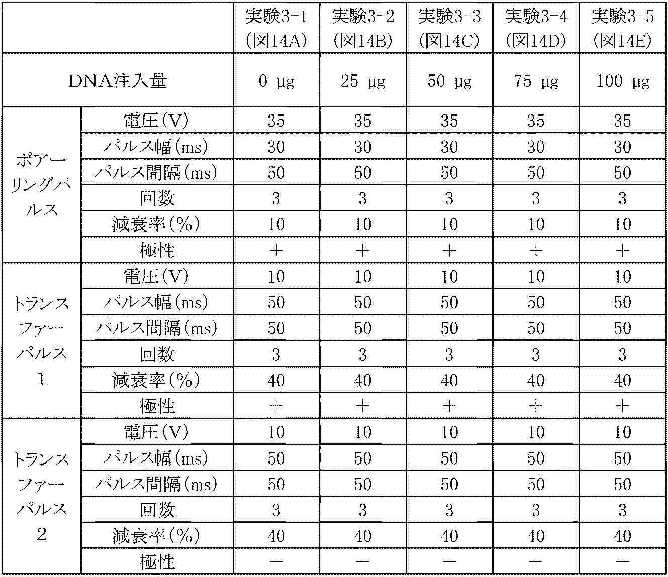
The present invention is expected to be used in life science fields such as molecular biology, genetic engineering, and cell biology, medical fields such as medicine and drug discovery, and livestock fields such as livestock and poultry. In particular, it is expected to be effectively used in the technical field using electroporation in vivo.
11 .第1極性電極針
12 .外枠支持体下部構造体
13 .電極針貫通孔
14 .第1極性用通電部
15 .開口部
16 .接続部
17 .配線、ケーブル
18 .配線保持部 10.
21 .シリンジヘッド装着部
22 .シリンジヘッド装着部外部構造体(外枠支持体上部構造体)
23 .シリンジヘッド装着部外部構造体内の空間
24 .シリンジヘッド装着部内部構造体
25 .シリンジヘッド装着部内部構造体内の空間
26 .シリンジヘッド装着部内部構造体の底部
27 .開口部
28 .配線、ケーブル
29 .配線保持部 20. Syringe holding part 21. Syringe
23. Space inside the external structure of the syringe
41 .シリンジ針挿入出路(シリンジヘッド装着部側)
42 .第2極性用通電部
43 .シリンジ針挿入出路(スペーサー部)
44 .シリンジ針挿入出路(外枠支持体下部構造体側)
45 .シリンジ針挿入出孔(シリンジヘッド装着部側)
46 .シリンジ針挿入出孔(外枠支持体下部構造体側)
47 .スペーサー部 40. Syringe
42. Second
44. Syringe needle insertion path (outer frame support lower structure side)
45. Syringe needle insertion hole (Syringe head mounting part side)
46. Syringe needle insertion hole (outer frame support lower structure side)
47. Spacer part
51 .シリンジヘッド
52 .シリンジ針
53 .注射筒
54 .プランジャー
55 .第2極性電極針 50. Syringe,
Claims (14)
- 複数の電極針を有するエレクトロポレーション用電極であって、
(A)第1極性電極針、電極針保持部、及びシリンジ保持部を含んでなる構造を有し、
(B)前記電極針保持部が、外枠支持体下部構造体及び第1極性用通電部を含んでなる構造体であって、前記外枠支持体下部構造体の底面にシリンジ保持部側と連通するシリンジ針挿入出孔を有し、
(C)前記外枠支持体下部構造体の底面から第1極性電極針がエレクトロポレーション対象物側に2本以上突出した構造を有し、
(D)(d-1)前記エレクトロポレーション用電極が、前記電極針保持部のエレクトロポレーション対象物側とは反対側に、シリンジ針を挿入してシリンジ装着可能なシリンジ保持部を備えた構造であって、(d-2)前記シリンジ保持部が、導電性材質で構成されてなる第2極性用通電部を少なくとも一部に備えたシリンジ針挿入出路を有する構造である、
ことを特徴とするエレクトロポレーション用電極。 An electroporation electrode having a plurality of electrode needles,
(A) having a structure including a first polarity electrode needle, an electrode needle holding portion, and a syringe holding portion;
(B) The electrode needle holding portion is a structure including an outer frame support lower structure and a first polarity energization portion, and a syringe holding portion side on the bottom surface of the outer frame support lower structure; It has a syringe needle insertion hole that communicates,
(C) It has a structure in which two or more first polar electrode needles protrude from the bottom surface of the outer frame support lower structure toward the electroporation object side,
(D) (d-1) The electrode for electroporation includes a syringe holding portion on the side opposite to the electroporation object side of the electrode needle holding portion so that a syringe needle can be inserted and attached to the syringe. (D-2) The syringe holding part is a structure having a syringe needle insertion / extraction path provided at least in part with a second polarity energization part made of a conductive material.
An electrode for electroporation characterized by the above. - 前記エレクトロポレーション用電極が、前記シリンジ保持部にシリンジを装着した際に、第2極性用通電部との接触を介してシリンジ針挿入出孔から突出したシリンジ針を第2極性電極針として使用可能とする部材電極である、請求項1に記載のエレクトロポレーション用電極。 When the electroporation electrode is mounted on the syringe holding part, the syringe needle protruding from the syringe needle insertion / extraction hole through contact with the second polarity energization part is used as the second polarity electrode needle. The electrode for electroporation according to claim 1, which is a member electrode that enables the electrode.
- 前記第1極性電極針が、
外枠支持体下部構造体の底面視にて第1極性電極針の先端を結ぶ直線上若しくは略直線上又は第1極性電極針の先端を頂点として形成される多角形の内側にシリンジ針挿入出孔が位置するように、配置されたものである、
請求項1又は2のいずれかに記載のエレクトロポレーション用電極。 The first polarity electrode needle is
Syringe needle insertion / extraction on a straight line or a substantially straight line connecting the tips of the first polarity electrode needles or a polygon formed with the tips of the first polarity electrode needles as apexes in the bottom view of the outer frame support lower structure It is arranged so that the hole is located,
The electrode for electroporation according to claim 1 or 2. - 前記シリンジ針挿入出路における第2極性用通電部の少なくとも一部が、導電性物質からなる直管構造を有する構造であって、シリンジ針挿入時にシリンジ針との接触が担保される内径又は内幅を有するものである、請求項1~3のいずれかに記載のエレクトロポレーション用電極。 At least a part of the second polarity energization part in the syringe needle insertion / extraction path has a structure having a straight tube structure made of a conductive substance, and an inner diameter or an inner width that ensures contact with the syringe needle when the syringe needle is inserted. The electrode for electroporation according to any one of claims 1 to 3, wherein
- 前記第1極性電極針が、電極針保持部の外枠支持体下部構造体を貫通して第1極性用通電部に接続された構造を有する、請求項1~4のいずれかに記載のエレクトロポレーション用電極。 The electro according to any one of claims 1 to 4, wherein the first polarity electrode needle has a structure in which the first polarity electrode needle penetrates the outer frame support lower structure of the electrode needle holding portion and is connected to the first polarity energization portion. Electrode for poration.
- 前記エレクトロポレーション用電極が、
(E)(e-1)前記第1極性電極針が、第1極性用通電部との接続部にて着脱可能な構造を有する、又は、(e-2)前記第1極性用通電部が分離可能な接続部を備えた構造を有する、ことによって前記外枠支持体下部構造体の一部又は全部と伴に前記第1極性電極針の着脱を可能とするものである、
請求項1~5のいずれかに記載のエレクトロポレーション用電極。 The electrode for electroporation is
(E) (e-1) The first polarity electrode needle has a structure that can be attached and detached at the connection portion with the first polarity energization portion, or (e-2) the first polarity energization portion is By having a structure with a separable connection part, it is possible to attach and detach the first polar electrode needle together with a part or all of the outer frame support lower structure.
The electrode for electroporation according to any one of claims 1 to 5. - 前記1極性電極針が突出する角度が、外枠支持体下部構造体の底面に対して垂直及び/又は略垂直方向である、請求項1~6のいずれかに記載のエレクトロポレーション用電極。 The electrode for electroporation according to any one of claims 1 to 6, wherein an angle at which the one-polar electrode needle protrudes is perpendicular and / or substantially perpendicular to the bottom surface of the outer frame support lower structure.
- 前記第1極性電極針の本数が3本以上である、請求項1~7のいずれかに記載のエレクトロポレーション用電極。 The electrode for electroporation according to any one of claims 1 to 7, wherein the number of the first polar electrode needles is 3 or more.
- 前記第1極性電極針が、外枠支持体下部構造体の底面視にてシリンジ針挿入出孔の中心から0.5~10mmの範囲に配置されたものである、請求項1~8のいずれかに記載のエレクトロポレーション用電極。 9. The method according to claim 1, wherein the first polarity electrode needle is disposed in a range of 0.5 to 10 mm from the center of the syringe needle insertion / extraction hole in a bottom view of the outer frame support lower structure. An electrode for electroporation according to claim 1.
- 前記第1極性電極針が、外枠支持体下部構造体の底面視にてシリンジ針挿入出孔を中心とする同心円上又は略同心円上に等間隔又は略等間隔に配置されたものである、請求項1~9のいずれかに記載のエレクトロポレーション用電極。 The first polar electrode needles are arranged on a concentric circle or a substantially concentric circle centered on the syringe needle insertion / exit hole at a bottom view of the outer frame support lower structure at regular intervals or substantially regular intervals. The electrode for electroporation according to any one of claims 1 to 9.
- 前記第1極性電極針が、電極針保持部における外枠支持体下部構造体の底面から突出した電極長にて1~10mmの固定電極針である、請求項1~10のいずれかに記載のエレクトロポレーション用電極。 11. The fixed electrode needle according to claim 1, wherein the first polarity electrode needle is a fixed electrode needle having an electrode length of 1 to 10 mm protruding from the bottom surface of the outer frame support lower structure in the electrode needle holding portion. Electroporation electrode.
- 請求項1~11のいずれかに記載のエレクトロポレーション用電極のシリンジ保持部にシリンジを装着してシリンジ針挿入出孔からシリンジ針が突出した構造を有し、第2極性用通電部との接触を介して当該突出したシリンジ針が第2極性電極針として機能することを特徴とする、エレクトロポレーション用電極。 A syringe is mounted on the syringe holding part of the electroporation electrode according to any one of claims 1 to 11, and the syringe needle protrudes from a syringe needle insertion / extraction hole, The electrode for electroporation, wherein the syringe needle protruding through contact functions as a second polarity electrode needle.
- 前記第2極性電極針となったシリンジ針が、シリンジ針挿入出孔から突出した針長において、外枠支持体下部構造体の底面から突出した第1極性電極針の平均針長と比較して-4~+2mmの範囲である、請求項12に記載のエレクトロポレーション用電極。 Compared with the average needle length of the first polarity electrode needle protruding from the bottom surface of the outer frame support lower structure in the needle length that the syringe needle that has become the second polarity electrode needle protrudes from the syringe needle insertion hole. The electrode for electroporation according to claim 12, which is in the range of -4 to +2 mm.
- 前記第1極性電極針、前記電極針保持部、及び前記シリンジ保持部を構成する部材を含んでなる、請求項1~13のいずれかに記載のエレクトロポレーション用電極の組立用キット。 The electroporation electrode assembly kit according to any one of claims 1 to 13, comprising members constituting the first polarity electrode needle, the electrode needle holding portion, and the syringe holding portion.
Priority Applications (4)
| Application Number | Priority Date | Filing Date | Title |
|---|---|---|---|
| CN201780011616.0A CN108778400B (en) | 2016-02-22 | 2017-02-02 | Electrode for electroporation |
| US16/077,979 US11517741B2 (en) | 2016-02-22 | 2017-02-02 | Electrodes for electroporation |
| EP17756131.3A EP3421078B1 (en) | 2016-02-22 | 2017-02-02 | Electrodes for electroporation |
| JP2017539032A JP6292705B2 (en) | 2016-02-22 | 2017-02-02 | Electroporation electrode |
Applications Claiming Priority (2)
| Application Number | Priority Date | Filing Date | Title |
|---|---|---|---|
| JP2016030984 | 2016-02-22 | ||
| JP2016-030984 | 2016-02-22 |
Publications (1)
| Publication Number | Publication Date |
|---|---|
| WO2017145689A1 true WO2017145689A1 (en) | 2017-08-31 |
Family
ID=59685206
Family Applications (1)
| Application Number | Title | Priority Date | Filing Date |
|---|---|---|---|
| PCT/JP2017/003733 WO2017145689A1 (en) | 2016-02-22 | 2017-02-02 | Electrodes for electroporation |
Country Status (5)
| Country | Link |
|---|---|
| US (1) | US11517741B2 (en) |
| EP (1) | EP3421078B1 (en) |
| JP (2) | JP6292705B2 (en) |
| CN (1) | CN108778400B (en) |
| WO (1) | WO2017145689A1 (en) |
Citations (7)
| Publication number | Priority date | Publication date | Assignee | Title |
|---|---|---|---|---|
| US4269174A (en) * | 1979-08-06 | 1981-05-26 | Medical Dynamics, Inc. | Transcutaneous vasectomy apparatus and method |
| JP2005518904A (en) * | 2002-03-07 | 2005-06-30 | マーク アンド カンパニー インコーポレイテッド | Clinical syringe with electrical stimulation aspect |
| US20080058706A1 (en) * | 2004-06-30 | 2008-03-06 | Genetronics, Inc. | Modular electroporation device with disposable electrode and drug delivery components |
| US20090030364A1 (en) * | 2005-02-04 | 2009-01-29 | The Johns Hopkins University | Electroporation gene therapy gun system |
| JP2010051828A (en) * | 2002-07-04 | 2010-03-11 | Inovio As | Electroporation device and infusion device |
| JP2011509743A (en) * | 2008-01-17 | 2011-03-31 | ジェネトロニクス,インコーポレイティド | Variable current density single needle electroporation system and method |
| JP2015163230A (en) * | 2004-06-24 | 2015-09-10 | スフェルゲン | Device for moving molecule to cell by using electric force |
Family Cites Families (9)
| Publication number | Priority date | Publication date | Assignee | Title |
|---|---|---|---|---|
| US5439440A (en) | 1993-04-01 | 1995-08-08 | Genetronics, Inc. | Electroporation system with voltage control feedback for clinical applications |
| US5993434A (en) | 1993-04-01 | 1999-11-30 | Genetronics, Inc. | Method of treatment using electroporation mediated delivery of drugs and genes |
| US7171264B1 (en) | 1999-05-10 | 2007-01-30 | Genetronics, Inc. | Intradermal delivery of active agents by needle-free injection and electroporation |
| US7245963B2 (en) * | 2002-03-07 | 2007-07-17 | Advisys, Inc. | Electrode assembly for constant-current electroporation and use |
| US6912417B1 (en) * | 2002-04-05 | 2005-06-28 | Ichor Medical Systmes, Inc. | Method and apparatus for delivery of therapeutic agents |
| US20060036210A1 (en) * | 2004-06-30 | 2006-02-16 | Lei Zhang | Modular electroporation device with disposable electrode and drug delivery components |
| ITTO20110309A1 (en) | 2011-04-05 | 2012-10-06 | Igea S P A | ADJUSTABLE HANDPIECE |
| CN103717249B (en) * | 2011-06-15 | 2017-03-22 | 克洛恩泰克制药股份公司 | Injection needle and device |
| KR101587930B1 (en) * | 2013-12-18 | 2016-01-22 | 정헌 | Electrod integrated needle apparatus for electroporation |
-
2017
- 2017-02-02 WO PCT/JP2017/003733 patent/WO2017145689A1/en active Application Filing
- 2017-02-02 US US16/077,979 patent/US11517741B2/en active Active
- 2017-02-02 EP EP17756131.3A patent/EP3421078B1/en active Active
- 2017-02-02 JP JP2017539032A patent/JP6292705B2/en active Active
- 2017-02-02 CN CN201780011616.0A patent/CN108778400B/en active Active
-
2018
- 2018-02-06 JP JP2018018858A patent/JP6777905B2/en active Active
Patent Citations (7)
| Publication number | Priority date | Publication date | Assignee | Title |
|---|---|---|---|---|
| US4269174A (en) * | 1979-08-06 | 1981-05-26 | Medical Dynamics, Inc. | Transcutaneous vasectomy apparatus and method |
| JP2005518904A (en) * | 2002-03-07 | 2005-06-30 | マーク アンド カンパニー インコーポレイテッド | Clinical syringe with electrical stimulation aspect |
| JP2010051828A (en) * | 2002-07-04 | 2010-03-11 | Inovio As | Electroporation device and infusion device |
| JP2015163230A (en) * | 2004-06-24 | 2015-09-10 | スフェルゲン | Device for moving molecule to cell by using electric force |
| US20080058706A1 (en) * | 2004-06-30 | 2008-03-06 | Genetronics, Inc. | Modular electroporation device with disposable electrode and drug delivery components |
| US20090030364A1 (en) * | 2005-02-04 | 2009-01-29 | The Johns Hopkins University | Electroporation gene therapy gun system |
| JP2011509743A (en) * | 2008-01-17 | 2011-03-31 | ジェネトロニクス,インコーポレイティド | Variable current density single needle electroporation system and method |
Non-Patent Citations (1)
| Title |
|---|
| See also references of EP3421078A4 * |
Also Published As
| Publication number | Publication date |
|---|---|
| JP2018065038A (en) | 2018-04-26 |
| JP6292705B2 (en) | 2018-03-14 |
| EP3421078A1 (en) | 2019-01-02 |
| JPWO2017145689A1 (en) | 2018-03-08 |
| US20210187276A1 (en) | 2021-06-24 |
| JP6777905B2 (en) | 2020-10-28 |
| CN108778400A (en) | 2018-11-09 |
| CN108778400B (en) | 2022-02-25 |
| US11517741B2 (en) | 2022-12-06 |
| EP3421078A4 (en) | 2019-10-30 |
| EP3421078B1 (en) | 2023-04-05 |
Similar Documents
| Publication | Publication Date | Title |
|---|---|---|
| US20230001190A1 (en) | Device and method for single-needle in vivo electroporation | |
| US8283171B2 (en) | Method and apparatus for avalanche-mediated transfer of agents into cells | |
| JP4321962B2 (en) | Method for the electroosmosis of individual solid cell structures and organelle structures and uses thereof | |
| JP5197006B2 (en) | Devices that move molecules to cells using electrical force | |
| JP2009527321A (en) | Methods and apparatus for avalanche-mediated introduction of drugs into cells | |
| US11052245B2 (en) | Device and method for localized delivery and extraction of material | |
| KR102583350B1 (en) | Electroporation device for the eye with a support and with a needle electrode | |
| JP6292705B2 (en) | Electroporation electrode | |
| CA2686855C (en) | Device and method for single-needle in vivo electroporation | |
| EP2319913A1 (en) | A multipurpose micro electric field networking cell processing device | |
| CN214484729U (en) | Thorax injection fixing device for animal | |
| US11471674B2 (en) | Electroosmotic convection-enhanced delivery system | |
| WO2024009535A1 (en) | Intraocular drug administration device, agent reservoir, and method for operating intraocular drug administration device | |
| Tang | Editorial (Hot Topic: Electroporation for Drug and Gene Delivery in Cancer Therapy) | |
| Mangold et al. | Murine Neural Plate Targeting by In Utero Nano-Injection (NEPTUNE) at Embryonic Day 7.5 | |
| CN117881449A (en) | Side port injection devices for electroporation and related systems and methods |
Legal Events
| Date | Code | Title | Description |
|---|---|---|---|
| ENP | Entry into the national phase |
Ref document number: 2017539032 Country of ref document: JP Kind code of ref document: A |
|
| NENP | Non-entry into the national phase |
Ref country code: DE |
|
| WWE | Wipo information: entry into national phase |
Ref document number: 2017756131 Country of ref document: EP |
|
| ENP | Entry into the national phase |
Ref document number: 2017756131 Country of ref document: EP Effective date: 20180924 |
|
| 121 | Ep: the epo has been informed by wipo that ep was designated in this application |
Ref document number: 17756131 Country of ref document: EP Kind code of ref document: A1 |